KR20200055007A - Component parts and base parts for inhaler, and manufacturing method - Google Patents
Component parts and base parts for inhaler, and manufacturing methodDownload PDFInfo
- Publication number
- KR20200055007A KR20200055007AKR1020207009664AKR20207009664AKR20200055007AKR 20200055007 AKR20200055007 AKR 20200055007AKR 1020207009664 AKR1020207009664 AKR 1020207009664AKR 20207009664 AKR20207009664 AKR 20207009664AKR 20200055007 AKR20200055007 AKR 20200055007A
- Authority
- KR
- South Korea
- Prior art keywords
- component
- evaporator
- base part
- inhaler
- component part
- Prior art date
- Legal status (The legal status is an assumption and is not a legal conclusion. Google has not performed a legal analysis and makes no representation as to the accuracy of the status listed.)
- Granted
Links
- 238000004519manufacturing processMethods0.000titleclaimsdescription13
- 239000007788liquidSubstances0.000claimsabstractdescription58
- 239000003571electronic cigaretteSubstances0.000claimsabstractdescription10
- 230000005611electricityEffects0.000claimsabstractdescription4
- 230000003993interactionEffects0.000claimsabstract2
- 230000002441reversible effectEffects0.000claimsabstract2
- 238000004146energy storageMethods0.000claimsdescription25
- 238000003860storageMethods0.000claimsdescription14
- 238000013500data storageMethods0.000claimsdescription12
- 239000002184metalSubstances0.000claimsdescription8
- 230000008054signal transmissionEffects0.000claimsdescription5
- 238000004891communicationMethods0.000claimsdescription4
- 230000001681protective effectEffects0.000claimsdescription4
- 238000001704evaporationMethods0.000claimsdescription3
- 238000005266castingMethods0.000claimsdescription2
- 230000001276controlling effectEffects0.000claimsdescription2
- 230000001105regulatory effectEffects0.000claimsdescription2
- 238000000034methodMethods0.000claims17
- 238000010438heat treatmentMethods0.000description32
- 238000005259measurementMethods0.000description9
- 238000013461designMethods0.000description5
- 239000004480active ingredientSubstances0.000description4
- 239000000463materialSubstances0.000description4
- 230000005540biological transmissionEffects0.000description3
- 230000002950deficientEffects0.000description3
- 238000012546transferMethods0.000description3
- 239000004020conductorSubstances0.000description2
- 238000005538encapsulationMethods0.000description2
- 239000000796flavoring agentSubstances0.000description2
- 235000019634flavorsNutrition0.000description2
- 230000006870functionEffects0.000description2
- 230000010354integrationEffects0.000description2
- 239000011664nicotinic acidSubstances0.000description2
- 239000000126substanceSubstances0.000description2
- SNICXCGAKADSCV-JTQLQIEISA-N(-)-NicotineChemical compoundCN1CCC[C@H]1C1=CC=CN=C1SNICXCGAKADSCV-JTQLQIEISA-N0.000description1
- 229920002430Fibre-reinforced plasticPolymers0.000description1
- HBBGRARXTFLTSG-UHFFFAOYSA-NLithium ionChemical compound[Li+]HBBGRARXTFLTSG-UHFFFAOYSA-N0.000description1
- 239000004696Poly ether ether ketoneSubstances0.000description1
- XUIMIQQOPSSXEZ-UHFFFAOYSA-NSiliconChemical compound[Si]XUIMIQQOPSSXEZ-UHFFFAOYSA-N0.000description1
- JUPQTSLXMOCDHR-UHFFFAOYSA-Nbenzene-1,4-diol;bis(4-fluorophenyl)methanoneChemical compoundOC1=CC=C(O)C=C1.C1=CC(F)=CC=C1C(=O)C1=CC=C(F)C=C1JUPQTSLXMOCDHR-UHFFFAOYSA-N0.000description1
- 239000000919ceramicSubstances0.000description1
- 238000004140cleaningMethods0.000description1
- 238000010276constructionMethods0.000description1
- 238000011109contaminationMethods0.000description1
- 238000010586diagramMethods0.000description1
- 230000008020evaporationEffects0.000description1
- 239000011151fibre-reinforced plasticSubstances0.000description1
- 239000012530fluidSubstances0.000description1
- 229910001416lithium ionInorganic materials0.000description1
- 239000000203mixtureSubstances0.000description1
- 229960002715nicotineDrugs0.000description1
- SNICXCGAKADSCV-UHFFFAOYSA-NnicotineNatural productsCN1CCCC1C1=CC=CN=C1SNICXCGAKADSCV-UHFFFAOYSA-N0.000description1
- 239000012811non-conductive materialSubstances0.000description1
- 238000013021overheatingMethods0.000description1
- 230000002093peripheral effectEffects0.000description1
- 239000004033plasticSubstances0.000description1
- 229920003023plasticPolymers0.000description1
- 229920002530polyetherether ketonePolymers0.000description1
- 229910052710siliconInorganic materials0.000description1
- 239000010703siliconSubstances0.000description1
- 238000012360testing methodMethods0.000description1
- 235000019505tobacco productNutrition0.000description1
- 230000007704transitionEffects0.000description1
Images


Classifications
- A—HUMAN NECESSITIES
- A24—TOBACCO; CIGARS; CIGARETTES; SIMULATED SMOKING DEVICES; SMOKERS' REQUISITES
- A24F—SMOKERS' REQUISITES; MATCH BOXES; SIMULATED SMOKING DEVICES
- A24F40/00—Electrically operated smoking devices; Component parts thereof; Manufacture thereof; Maintenance or testing thereof; Charging means specially adapted therefor
- A24F40/10—Devices using liquid inhalable precursors
- A—HUMAN NECESSITIES
- A61—MEDICAL OR VETERINARY SCIENCE; HYGIENE
- A61M—DEVICES FOR INTRODUCING MEDIA INTO, OR ONTO, THE BODY; DEVICES FOR TRANSDUCING BODY MEDIA OR FOR TAKING MEDIA FROM THE BODY; DEVICES FOR PRODUCING OR ENDING SLEEP OR STUPOR
- A61M15/00—Inhalators
- A61M15/08—Inhaling devices inserted into the nose
- A—HUMAN NECESSITIES
- A24—TOBACCO; CIGARS; CIGARETTES; SIMULATED SMOKING DEVICES; SMOKERS' REQUISITES
- A24F—SMOKERS' REQUISITES; MATCH BOXES; SIMULATED SMOKING DEVICES
- A24F40/00—Electrically operated smoking devices; Component parts thereof; Manufacture thereof; Maintenance or testing thereof; Charging means specially adapted therefor
- A24F40/40—Constructional details, e.g. connection of cartridges and battery parts
- A—HUMAN NECESSITIES
- A24—TOBACCO; CIGARS; CIGARETTES; SIMULATED SMOKING DEVICES; SMOKERS' REQUISITES
- A24F—SMOKERS' REQUISITES; MATCH BOXES; SIMULATED SMOKING DEVICES
- A24F40/00—Electrically operated smoking devices; Component parts thereof; Manufacture thereof; Maintenance or testing thereof; Charging means specially adapted therefor
- A24F40/50—Control or monitoring
- A—HUMAN NECESSITIES
- A24—TOBACCO; CIGARS; CIGARETTES; SIMULATED SMOKING DEVICES; SMOKERS' REQUISITES
- A24F—SMOKERS' REQUISITES; MATCH BOXES; SIMULATED SMOKING DEVICES
- A24F40/00—Electrically operated smoking devices; Component parts thereof; Manufacture thereof; Maintenance or testing thereof; Charging means specially adapted therefor
- A24F40/60—Devices with integrated user interfaces
- A—HUMAN NECESSITIES
- A24—TOBACCO; CIGARS; CIGARETTES; SIMULATED SMOKING DEVICES; SMOKERS' REQUISITES
- A24F—SMOKERS' REQUISITES; MATCH BOXES; SIMULATED SMOKING DEVICES
- A24F40/00—Electrically operated smoking devices; Component parts thereof; Manufacture thereof; Maintenance or testing thereof; Charging means specially adapted therefor
- A24F40/65—Devices with integrated communication means, e.g. wireless communication means
- A—HUMAN NECESSITIES
- A24—TOBACCO; CIGARS; CIGARETTES; SIMULATED SMOKING DEVICES; SMOKERS' REQUISITES
- A24F—SMOKERS' REQUISITES; MATCH BOXES; SIMULATED SMOKING DEVICES
- A24F40/00—Electrically operated smoking devices; Component parts thereof; Manufacture thereof; Maintenance or testing thereof; Charging means specially adapted therefor
- A24F40/70—Manufacture
- A—HUMAN NECESSITIES
- A24—TOBACCO; CIGARS; CIGARETTES; SIMULATED SMOKING DEVICES; SMOKERS' REQUISITES
- A24F—SMOKERS' REQUISITES; MATCH BOXES; SIMULATED SMOKING DEVICES
- A24F40/00—Electrically operated smoking devices; Component parts thereof; Manufacture thereof; Maintenance or testing thereof; Charging means specially adapted therefor
- A24F40/90—Arrangements or methods specially adapted for charging batteries thereof
- A—HUMAN NECESSITIES
- A61—MEDICAL OR VETERINARY SCIENCE; HYGIENE
- A61M—DEVICES FOR INTRODUCING MEDIA INTO, OR ONTO, THE BODY; DEVICES FOR TRANSDUCING BODY MEDIA OR FOR TAKING MEDIA FROM THE BODY; DEVICES FOR PRODUCING OR ENDING SLEEP OR STUPOR
- A61M11/00—Sprayers or atomisers specially adapted for therapeutic purposes
- A61M11/04—Sprayers or atomisers specially adapted for therapeutic purposes operated by the vapour pressure of the liquid to be sprayed or atomised
- A61M11/041—Sprayers or atomisers specially adapted for therapeutic purposes operated by the vapour pressure of the liquid to be sprayed or atomised using heaters
- A61M11/042—Sprayers or atomisers specially adapted for therapeutic purposes operated by the vapour pressure of the liquid to be sprayed or atomised using heaters electrical
- A—HUMAN NECESSITIES
- A61—MEDICAL OR VETERINARY SCIENCE; HYGIENE
- A61M—DEVICES FOR INTRODUCING MEDIA INTO, OR ONTO, THE BODY; DEVICES FOR TRANSDUCING BODY MEDIA OR FOR TAKING MEDIA FROM THE BODY; DEVICES FOR PRODUCING OR ENDING SLEEP OR STUPOR
- A61M15/00—Inhalators
- A61M15/0001—Details of inhalators; Constructional features thereof
- A—HUMAN NECESSITIES
- A61—MEDICAL OR VETERINARY SCIENCE; HYGIENE
- A61M—DEVICES FOR INTRODUCING MEDIA INTO, OR ONTO, THE BODY; DEVICES FOR TRANSDUCING BODY MEDIA OR FOR TAKING MEDIA FROM THE BODY; DEVICES FOR PRODUCING OR ENDING SLEEP OR STUPOR
- A61M15/00—Inhalators
- A61M15/06—Inhaling appliances shaped like cigars, cigarettes or pipes
- H—ELECTRICITY
- H01—ELECTRIC ELEMENTS
- H01R—ELECTRICALLY-CONDUCTIVE CONNECTIONS; STRUCTURAL ASSOCIATIONS OF A PLURALITY OF MUTUALLY-INSULATED ELECTRICAL CONNECTING ELEMENTS; COUPLING DEVICES; CURRENT COLLECTORS
- H01R24/00—Two-part coupling devices, or either of their cooperating parts, characterised by their overall structure
- H01R24/60—Contacts spaced along planar side wall transverse to longitudinal axis of engagement
- H01R24/62—Sliding engagements with one side only, e.g. modular jack coupling devices
- A—HUMAN NECESSITIES
- A61—MEDICAL OR VETERINARY SCIENCE; HYGIENE
- A61M—DEVICES FOR INTRODUCING MEDIA INTO, OR ONTO, THE BODY; DEVICES FOR TRANSDUCING BODY MEDIA OR FOR TAKING MEDIA FROM THE BODY; DEVICES FOR PRODUCING OR ENDING SLEEP OR STUPOR
- A61M15/00—Inhalators
- A61M15/02—Inhalators with activated or ionised fluids, e.g. electrohydrodynamic [EHD] or electrostatic devices; Ozone-inhalators with radioactive tagged particles
- A61M15/025—Bubble jet droplet ejection devices
- A—HUMAN NECESSITIES
- A61—MEDICAL OR VETERINARY SCIENCE; HYGIENE
- A61M—DEVICES FOR INTRODUCING MEDIA INTO, OR ONTO, THE BODY; DEVICES FOR TRANSDUCING BODY MEDIA OR FOR TAKING MEDIA FROM THE BODY; DEVICES FOR PRODUCING OR ENDING SLEEP OR STUPOR
- A61M16/00—Devices for influencing the respiratory system of patients by gas treatment, e.g. ventilators; Tracheal tubes
- A61M16/0003—Accessories therefor, e.g. sensors, vibrators, negative pressure
- A61M2016/0027—Accessories therefor, e.g. sensors, vibrators, negative pressure pressure meter
- A—HUMAN NECESSITIES
- A61—MEDICAL OR VETERINARY SCIENCE; HYGIENE
- A61M—DEVICES FOR INTRODUCING MEDIA INTO, OR ONTO, THE BODY; DEVICES FOR TRANSDUCING BODY MEDIA OR FOR TAKING MEDIA FROM THE BODY; DEVICES FOR PRODUCING OR ENDING SLEEP OR STUPOR
- A61M2205/00—General characteristics of the apparatus
- A61M2205/33—Controlling, regulating or measuring
- A61M2205/3379—Masses, volumes, levels of fluids in reservoirs, flow rates
- A61M2205/3389—Continuous level detection
- A—HUMAN NECESSITIES
- A61—MEDICAL OR VETERINARY SCIENCE; HYGIENE
- A61M—DEVICES FOR INTRODUCING MEDIA INTO, OR ONTO, THE BODY; DEVICES FOR TRANSDUCING BODY MEDIA OR FOR TAKING MEDIA FROM THE BODY; DEVICES FOR PRODUCING OR ENDING SLEEP OR STUPOR
- A61M2205/00—General characteristics of the apparatus
- A61M2205/36—General characteristics of the apparatus related to heating or cooling
- A61M2205/3653—General characteristics of the apparatus related to heating or cooling by Joule effect, i.e. electric resistance
- A—HUMAN NECESSITIES
- A61—MEDICAL OR VETERINARY SCIENCE; HYGIENE
- A61M—DEVICES FOR INTRODUCING MEDIA INTO, OR ONTO, THE BODY; DEVICES FOR TRANSDUCING BODY MEDIA OR FOR TAKING MEDIA FROM THE BODY; DEVICES FOR PRODUCING OR ENDING SLEEP OR STUPOR
- A61M2205/00—General characteristics of the apparatus
- A61M2205/50—General characteristics of the apparatus with microprocessors or computers
- A61M2205/502—User interfaces, e.g. screens or keyboards
- A—HUMAN NECESSITIES
- A61—MEDICAL OR VETERINARY SCIENCE; HYGIENE
- A61M—DEVICES FOR INTRODUCING MEDIA INTO, OR ONTO, THE BODY; DEVICES FOR TRANSDUCING BODY MEDIA OR FOR TAKING MEDIA FROM THE BODY; DEVICES FOR PRODUCING OR ENDING SLEEP OR STUPOR
- A61M2205/00—General characteristics of the apparatus
- A61M2205/82—Internal energy supply devices
- A61M2205/8206—Internal energy supply devices battery-operated
- A61M2205/8212—Internal energy supply devices battery-operated with means or measures taken for minimising energy consumption
- H—ELECTRICITY
- H01—ELECTRIC ELEMENTS
- H01R—ELECTRICALLY-CONDUCTIVE CONNECTIONS; STRUCTURAL ASSOCIATIONS OF A PLURALITY OF MUTUALLY-INSULATED ELECTRICAL CONNECTING ELEMENTS; COUPLING DEVICES; CURRENT COLLECTORS
- H01R2105/00—Three poles
- H—ELECTRICITY
- H02—GENERATION; CONVERSION OR DISTRIBUTION OF ELECTRIC POWER
- H02J—CIRCUIT ARRANGEMENTS OR SYSTEMS FOR SUPPLYING OR DISTRIBUTING ELECTRIC POWER; SYSTEMS FOR STORING ELECTRIC ENERGY
- H02J7/00—Circuit arrangements for charging or depolarising batteries or for supplying loads from batteries
- H02J7/0042—Circuit arrangements for charging or depolarising batteries or for supplying loads from batteries characterised by the mechanical construction
Landscapes
- Health & Medical Sciences (AREA)
- Engineering & Computer Science (AREA)
- Public Health (AREA)
- General Health & Medical Sciences (AREA)
- Veterinary Medicine (AREA)
- Anesthesiology (AREA)
- Biomedical Technology (AREA)
- Heart & Thoracic Surgery (AREA)
- Hematology (AREA)
- Life Sciences & Earth Sciences (AREA)
- Animal Behavior & Ethology (AREA)
- Bioinformatics & Cheminformatics (AREA)
- Pulmonology (AREA)
- Otolaryngology (AREA)
- Human Computer Interaction (AREA)
- Computer Networks & Wireless Communication (AREA)
- Infusion, Injection, And Reservoir Apparatuses (AREA)
- Cooling Or The Like Of Semiconductors Or Solid State Devices (AREA)
- Measuring Volume Flow (AREA)
Abstract
Translated fromKorean
Description
Translated fromKorean본 발명은 흡입기용, 바람직하게 전자 담배 제품용 구성 부품에 관한 것으로서, 그러한 구성 부품은 캐리어(carrier), 증발기에 공급되는 액체를 증발시키기 위해서 캐리어 상에 배열되는 전기 증발기, 및 증발기에 전기 에너지를 공급하기 위한 및/또는 증발기를 위한 제어 신호를 수신하기 위한 전기 연결부를 포함한다. 본 발명은 또한 흡입기용 기부 부품에 관한 것으로서, 그러한 기부 부품은 전자 제어 장치, 및 제어 신호를 구성 부품에 전송하기 위한 및/또는 흡입기의 구성 부품의 전기 공급을 위한 전기 연결부를 포함한다. 본 발명은 또한 그러한 구성 부품 및/또는 기부 부품을 생산하기 위한 방법에 관한 것이다.The present invention relates to a component for an inhaler, preferably for an electronic cigarette product, the component being a carrier, an electric evaporator arranged on a carrier to vaporize the liquid supplied to the evaporator, and electric energy to the evaporator. And electrical connections for supplying and / or receiving control signals for the evaporator. The present invention also relates to a base part for an inhaler, the base part comprising an electronic control device and an electrical connection for transmitting control signals to the component part and / or for supplying electricity to the component parts of the inhaler. The invention also relates to a method for producing such component parts and / or base parts.
시장에서의 흡입기 및 전자 담배 제품의 많은 비율이 풍미 물질 및/또는 활성 성분을 포함하는 액체의 증발을 기초로 한다. 원칙적으로, 이러한 목적을 위해서, 에너지 저장부, 일회용 부품으로서의 구성 부품, 재사용 가능 부품으로서의 기부 부품, 및 액체 저장 탱크가 제공된다.A large proportion of inhaler and e-cigarette products on the market are based on evaporation of liquids containing flavoring substances and / or active ingredients. In principle, for this purpose, an energy reservoir, a component part as a disposable part, a base part as a reusable part, and a liquid storage tank are provided.
재사용 가능하고, 교체 가능하며, 재충전 또는 재충진 가능한 구성요소를 갖는 일회용 담배 제품 및 전자 담배 제품의 실시예가 US 2014/0060554 A1에서 설명되어 있다.Embodiments of disposable tobacco products and electronic cigarette products with reusable, replaceable, refillable or refillable components are described in US 2014/0060554 A1.
재사용 가능 제품은, 하우징, 전자기기 및/또는 에너지 저장부와 같은 기부 구성요소가 재사용될 수 있다는 사실을 특징으로 한다. 예를 들어, 액체 저장 탱크 및/또는 증발기가 교환 가능할 수 있다.Reusable products are characterized by the fact that base components such as housings, electronics and / or energy storage can be reused. For example, the liquid storage tank and / or evaporator may be exchangeable.
배터리 및 교환 가능한 또는 재충진 가능한 카트리지를 갖는 재사용 가능 기부 유닛을 가지는 전자 담배 제품의 예가 EP 1 154 815 B1에 설명되어 있다.An example of an electronic cigarette product having a reusable base unit having a battery and a replaceable or refillable cartridge is described in EP 1 154 815 B1.
모듈형 전자 담배 제품이 DE 10 2014 207 277 A1에 설명되어 있다. 이러한 예에서, 전자 담배 제품은 다수의 단편들(segments)로 분할된다. 각각의 단편은 적어도 하나의 구성요소, 예를 들어 전기 에너지 공급원, 액체 탱크 및 가열 요소를 포함한다.Modular electronic cigarette products are described in DE 10 2014 207 277 A1. In this example, the electronic cigarette product is divided into a number of segments. Each piece includes at least one component, for example an electrical energy source, a liquid tank and a heating element.
다양한 실시예로 인해서, 품질, 가격 및 조립 용이성 사이의 균형을 달성하기 위해서, 전자 담배 제품의 구성요소에서 상이한 요건들이 요구된다.Due to various embodiments, different requirements are required in the components of the electronic cigarette product to achieve a balance between quality, price and ease of assembly.
현재, 하나 초과의 가열 채널을 제어할 수 있는 해결책이 존재하지 않는다. 단일-채널 접촉 시스템은 단일-채널 가열 장치를 제어할 수 있는 가능성을 제공한다. 채널들 사이의 기준 측정(reference measurement)은 가능하지 않고, 그에 따라 결함 채널 또는 더러운 콘택에 관한 진술(statement)이 만들어질 수 없다.Currently, there is no solution to control more than one heating channel. The single-channel contact system provides the possibility to control the single-channel heating device. Reference measurement between channels is not possible, and thus a statement about a defective channel or dirty contact cannot be made.
전기 콘택은 주로 증발기에 근접하여 배열되고 그에 따라 오염되기 쉽다.The electrical contacts are mainly arranged close to the evaporator and are therefore likely to be contaminated.
본 발명의 목적은, 상이한 공급자들의 요건을 만족시키는, 그리고 비용-효과적으로 그리고 단순한 조립에 의해서 통합될 수 있는 흡입기용 구성요소를 제공하는 것뿐만 아니라, 상응 생산 방법을 구체화하는 것이다.The object of the present invention is to provide a component for the inhaler that meets the requirements of different suppliers, and which can be integrated cost-effectively and by simple assembly, as well as embodying the corresponding production method.
본 발명의 목적은 독립항의 특징에 의해서 달성된다.The object of the present invention is achieved by the features of the independent claims.
본 발명에 따라 서로 연결되는 플러그 연결기 부품들의 제공은, 구성 부품과 기부 부품의 단순하고, 신속하며, 오류가 없는 연결을 가능하게 한다. 본 발명은 구성 부품과 기부 부품 사이의 조립-친화적이고 유리한, 표준화된 전기적 인터페이스 또는 연결을 제공하고, 다양한 증발기 및 증발기 개념의 시스템 통합을 가능하게 한다. 형성된 인터페이스로 인해서, 생산 중에 요구되는 테스트가 적은 노력으로 그리고 표준화된 방식으로 실행될 수 있다. 본 발명을 자동화된 조립에서 적용할 수 있다.The provision of plug connector parts which are connected to each other according to the present invention enables a simple, fast and error-free connection of the component parts and the base parts. The present invention provides an assembly-friendly and advantageous, standardized electrical interface or connection between the component part and the base part, and enables system integration of various evaporator and evaporator concepts. Due to the interface formed, the tests required during production can be carried out with little effort and in a standardized way. The invention can be applied in automated assembly.
증발기를 구성요소 부품 내로 통합하는 것으로 인해서, 복잡한 증발기의 세정이 필요치 않은데, 이는 구성 부품이 그 계획된 유효 수명 이후에 증발기와 함께 폐기될 수 있기 때문이다.By integrating the evaporator into the component parts, cleaning of the complex evaporator is not necessary, since the component can be discarded with the evaporator after its planned useful life.
유리하게, 구성 부품의 그리고 기부 부품의 플러그 연결기 부품들이 플러그 및 소켓에 의해서 형성된다. 플러그 연결기는 강건하고 안정적인 구축을 가능하게 하며, 그에 따라 증발기의 가열 요소의 최대의 보호를 가능하게 한다. 플러그가 구성 부품 상에 배열되고 소켓이 기부 부품 상에 배열되는 것이 유리할 수 있는데, 이는, 이러한 경우에, 구성 부품이 기부 부품 내로 활주하기가 더 용이하기 때문이다. 그러나, 소켓이 구성 부품 상에 배열되고 플러그가 기부 부품 상에 배열되는 반대의 경우가 배제되는 것은 아니다. 특히 큰 전도성의 콘택을 갖는 플러그에 의해서, 기부 부품에 대한 구성 부품의 확실한 전기적 연결이 실현될 수 있다.Advantageously, the plug connector parts of the component part and of the base part are formed by plugs and sockets. The plug connector allows for a robust and stable construction and thus maximum protection of the heating elements of the evaporator. It can be advantageous for the plug to be arranged on the component part and the socket on the base part, since in this case it is easier for the component part to slide into the base part. However, the opposite is not excluded, where the socket is arranged on the component part and the plug is arranged on the base part. Particularly by means of a plug having a large conductivity contact, reliable electrical connection of the component to the base component can be realized.
바람직하게, 구성 부품의 그리고 기부 부품의 플러그 연결기 부품의 각각이 적어도 3개의 상이하게 할당될 수 있는 또는 배치되는 금속 콘택을 갖는다. 이는 복수의 가열 요소 또는 가열 채널의 제어뿐만 아니라, 상이한 가열 요소들 또는 가열 채널들 사이의 기준 측정을 가능하게 하고, 그에 따라 결함이 있는 가열 채널 또는 더러운 콘택에 관한 진술이 가능하게 한다. 유리하게, 상응하는 수의 라인으로 증발기의 차별화된 제어 및/또는 측정을 가능하게 하기 위해서, 적어도 4개, 더 유리하게 적어도 5개의 상이하게 할당 가능한 또는 배치되는 금속 콘택이 제공된다. 그에 따라, 전기 연결이, 구성 부품과 기부 부품 사이에서, 전력 공급 라인 이외에, 적어도 하나의 디지털 데이터 라인 및/또는 적어도 하나의 아날로그 신호 라인을 포함하는 것이 유리하다.Preferably, each of the component part and the plug connector part of the base part has at least three differently assignable or arranged metal contacts. This enables control of a plurality of heating elements or heating channels, as well as reference measurements between different heating elements or heating channels, thus making it possible to make statements regarding defective heating channels or dirty contacts. Advantageously, at least 4, more advantageously at least 5 differently assignable or placed metal contacts are provided to enable differentiated control and / or measurement of the evaporator with a corresponding number of lines. Accordingly, it is advantageous that the electrical connection comprises at least one digital data line and / or at least one analog signal line, between the component part and the base part, in addition to the power supply line.
유리한 실시예에서, 금속 콘택은 부분적으로 플러그 연결기 부품의 상단 측면 및/또는 하단 측면에 배열된다. 이는, 콤팩트한 설계뿐만 아니라 안전한 신호/에너지 전송을 가능하게 한다. 일부 실시예에서, 플러그 연결기 부품의 상단 측면 및 하단 측면 상의 상응 콘택들이 각각의 경우에 180 °만큼 회전 대칭적으로(즉, 점 거울대칭 방식(point mirrored manner))으로 배열될 수 있고 동일하게 배치될 수 있다. 이는, 플러그 연결기 부품들을 연결할 때, 그러한 부품들의 서로에 대한 정확한 배열에 주의를 기울일 필요가 없다는 장점을 갖는다.In an advantageous embodiment, the metal contacts are partially arranged on the top side and / or the bottom side of the plug connector component. This allows for safe signal / energy transmission as well as compact design. In some embodiments, corresponding contacts on the top and bottom sides of the plug connector component can be arranged in a rotationally symmetrical manner (ie, point mirrored manner) by 180 ° in each case and placed identically Can be. This has the advantage that when connecting plug connector parts, it is not necessary to pay attention to the correct arrangement of such parts with respect to each other.
유리한 실시예에서, 플러그는 판-형상의 기부 부품을 가지며, 금속 콘택은 유리하게 기부 부품의 상단부 측면 및/또는 하단부 측면에 배열된다.In an advantageous embodiment, the plug has a plate-shaped base part, and the metal contacts are advantageously arranged on the top side and / or bottom side of the base part.
바람직하게, 구성 부품의 캐리어는 캐리어와 액체 탱크의 연결을 위한 규정된 액체 인터페이스를 갖는다. 이는, 공급자에 따라 달라지는 다양한 액체 탱크의 단순하고 표준화된 연결을 가능하게 한다.Preferably, the carrier of the component part has a defined liquid interface for the connection of the carrier and the liquid tank. This allows for a simple and standardized connection of various liquid tanks depending on the supplier.
바람직하게, 증발기 및 전자 구성요소는 판-형상의 캐리어의 일 측면 상에 배열되고 액체 인터페이스는 판-형상의 캐리어의 다른 측면 상에 배열된다. 이러한 경우에, 캐리어는 유리하게 액체 인터페이스로부터 증발기로 액체를 운송하기 위한 적어도 하나의 관통-개구부를 갖는다. 유리하게, 액체 인터페이스로부터 증발기로의 액체 운송 및 액체 공급을 지원하기 위해서, 적어도 하나의 모세관 요소가 관통-개구부 내에 배열될 수 있다.Preferably, the evaporator and electronic components are arranged on one side of the plate-shaped carrier and the liquid interface is arranged on the other side of the plate-shaped carrier. In this case, the carrier advantageously has at least one through-opening for transporting liquid from the liquid interface to the evaporator. Advantageously, at least one capillary element can be arranged in the through-opening to support liquid delivery and liquid supply from the liquid interface to the evaporator.
바람직하게, 구성 부품은 증발기를 제어 및/또는 조절하기 위한 전자 제어 장치를 갖는다. 바람직하게, 구성 부품은 구성 부품을 위한 식별자의 영구적인 저장을 위한 전자 메모리를 갖는다. 기부 부품은 유리하게 데이터 저장부를 포함하고, 데이터 저장부 내에는 복수의 상이한 증발기들에 상응하는 복수의 식별자들에 대한 제어 데이터가 영구적으로 저장된다. 기부 부품에 대한 구성 부품의 연결의 결과로서, 즉 상응 플러그 연결기들을 연결하는 것에 의해서, 기부 부품의 전자 제어 장치는 구성 부품의 전자 메모리로부터 식별자를 판독할 수 있고 구성 부품의 각각의 증발기의 유형-특이적인(type-specific) 개별적인 제어를 실시할 수 있다.Preferably, the component part has an electronic control device for controlling and / or regulating the evaporator. Preferably, the component part has an electronic memory for permanent storage of the identifier for the component part. The base part advantageously comprises a data storage, in which control data for a plurality of identifiers corresponding to a plurality of different evaporators is permanently stored. As a result of the connection of the component to the base component, ie by connecting the corresponding plug connectors, the electronic control device of the base component can read the identifier from the electronic memory of the component and the type of each evaporator of the component- Individual control of type-specific can be implemented.
바람직하게, 구성 부품은 증발기의 동작 상태를 검출하기 위한 하나 이상의 센서, 예를 들어 가열 온도를 측정하기 위한, 또한 간접적으로 가열 저항기를 측정하는 것에 의한 온도 센서, 및/또는 유동 압력을 측정하기 위한 압력 센서를 갖는다. 유리하게, 한편으로 전자 제어 장치와 다른 한편으로 증발기 및/또는 센서 사이의 전기 연결은, 전력 공급 라인 이외에, 적어도 하나의 아날로그 또는 디지털 신호 전송 라인을 가지며, 그러한 전송 라인에 의해서 센서 신호가 전자 제어 장치에 전송될 수 있다.Preferably, the component part is provided with one or more sensors for detecting the operating state of the evaporator, for example for measuring the heating temperature, and also for measuring the flow pressure and / or the temperature sensor by measuring the heating resistor indirectly. Has a pressure sensor. Advantageously, the electrical connection between the electronic control device on the one hand and the evaporator and / or sensor on the other hand has at least one analog or digital signal transmission line, in addition to the power supply line, by which the sensor signal is electronically controlled. Device.
바람직하게, 기부 부품은 전자 제어 장치를 에너지 저장 유닛에 연결하기 위한 규정된 배터리 인터페이스를 갖는다. 이는, 공급자에 따라 달라지는 넓은 범위의 에너지 저장 시스템의 단순하고 표준화된 연결을 가능하게 한다. 에너지 저장 유닛과 기부 부품의 전자 제어 장치 사이의 신호 또는 데이터의 송신 및 수신을 가능하게 하기 위해서, 배터리 인터페이스는 유리하게, 공급 라인 이외에, 적어도 하나의 신호 라인 또는 데이터 라인을 갖는다.Preferably, the base part has a defined battery interface for connecting the electronic control device to the energy storage unit. This enables a simple and standardized connection of a wide range of energy storage systems that vary from supplier to supplier. To enable transmission and reception of signals or data between the energy storage unit and the electronic control device of the base part, the battery interface advantageously has at least one signal line or data line in addition to the supply line.
유리하게, 기부 부분은 사용자 단말기와 무선 통신하기 위한 무선 모듈을 갖는다. 이는, 사용자가 흡입기로부터 데이터를 판독할 수 있게 하고, 흡입기 내의 설정을 할 수 있게 하고, 기타 등등을 할 수 있게 한다.Advantageously, the base portion has a wireless module for wireless communication with a user terminal. This allows the user to read data from the inhaler, make settings in the inhaler, and so on.
바람직하게, 기부 부품은 재사용 가능 부품이다. 유리한 실시예에서, 구성 부품은 일회용 부품일 수 있다. 구성 부품은 다른 실시예에서 재사용 가능 부품일 수 있다. 예를 들어, 액체 탱크 및 증발기를 가지는 구성 부품을 재충진 후에 재사용하는 것을 생각할 수 있다.Preferably, the base part is a reusable part. In an advantageous embodiment, the component parts can be disposable parts. The component parts may be reusable parts in other embodiments. For example, it is conceivable to reuse the components having the liquid tank and evaporator after refilling.
이하에서, 첨부 도면을 참조하여 바람직한 실시예를 기초로 본 발명을 설명한다.Hereinafter, the present invention will be described based on preferred embodiments with reference to the accompanying drawings.
도 1은 본 발명의 실시예의 구성 부품 및 기부 부품을 갖는 흡입기의 구성요소를 도시한다.
도 2는 조립된 구성 부품 및 제어 유닛의 사시도이다.
도 3은 도 2의 구성 부품의 분해도이다.
도 4는 추가적인 실시예 내의 구성 부품의 사시도이다.
도 5는 증발기의 영역 내의, 도 4에 도시된 구성 부품을 통한 횡단면이다.
도 6은 흡입기의 개략적인 전자 플러깅 선도이다.1 shows the components of an inhaler with a component part and a base part in an embodiment of the invention.
2 is a perspective view of the assembled component and control unit.
3 is an exploded view of the component parts of FIG. 2.
4 is a perspective view of component parts in a further embodiment.
5 is a cross-section through the component part shown in FIG. 4 in the region of the evaporator.
6 is a schematic electronic plugging diagram of the inhaler.
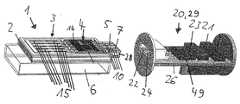
도 1에 도시된 막대-형상의 흡입기(27)가 구성 부품(1) 및 재사용이 가능한 기부 부품(20)을 포함하고, 구성 부품은 일회용 부품 또는 재사용 가능 부품일 수 있고, 기부 부품은 그에 따라 유리하게 재사용 가능 부품이다.The rod-shaped
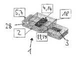
구성 부품(1)은 캐리어 판으로도 지칭될 수 있는 캐리어(2), 및 캐리어(2)에 연결되는 또는 연결된 액체 탱크(6)를 포함한다. 캐리어(2) 상에서, 디지털 전자 제어 장치(4), 예를 들어 주문형 집적 회로(ASIC)가 배열된다. 바람직하게, 전자 제어 장치(4)는 기준 저항기(분로(shunt)) 상에서 측정을 하는 전자 구성요소, 및 다른 통합된 제어 전자기기, 예를 들어 회로망을 위한 MOSFET, 저항 측정을 위한 기준 저항기(분로)), 및 센서(51)를 포함한다. 전자 제어 장치(4)는 바람직하게, 증발기(3)의 여러 채널의 제어를 실행하기 위해서, 다중화기 및/또는 슬라이딩 레지스터(sliding register)를 포함한다. 일반적으로, 캐리어(2)는 증발기(3) 및 가열 요소(15)를 제어하기 위해서 이용되는 모든 전자 구성요소, 특히 제어 장치(4), MOSFET, 분로 등뿐만 아니라, 전자 식별 하드웨어, 특히 전자 메모리(14)를 수용하는 역할을 한다.The component part 1 comprises a
캐리어(2)는 또한 복수의 전기 콘택(10)을 가지는 전기 플러그(5) 형태의 전기 플러그 연결기 부품(7)을 갖는다. 콘택(10)은, 센서 신호, 제어 신호 및/또는 전기 에너지를 전송하기 위해서, 적어도 부분적으로 캐리어(2) 상에서 및/또는 캐리어(2)에서 연장되는 전기 와이어에 의해서 전자 구성요소(4, 14)에 연결된다. 유리하게 연속적이고 형상-안정적인 캐리어(2)는 적합한, 그리고 유리하게 비-전도성인 재료, 예를 들어 세라믹 또는 적합한 플라스틱 재료, 특히 PEEK, 또는 섬유-보강 플라스틱 재료로 이루어질 수 있다. 가열 온도를 측정하기 위한 온도 센서 및/또는 유동 압력을 측정하기 위한 압력 센서와 같은 센서가 구성 부품 상에 제공될 수 있다.The
증발기(3)가 캐리어(2) 상에 배열되고, 증발기는 액체 탱크(6)로부터 공급되는 액체를 증발시킨다. 그에 따라, 캐리어(2)는, 그 접촉을 포함하여, 증발기(3)를 수용한다. 특히 전기적인 증발기(3)는 적어도 하나의, 바람직하게 복수의 전기 저항 가열 요소(15)를 갖는다. 증발기(3)는 바람직하게 캐리어(2)의 상단 측면에 배열된다. 가열 요소(15)의 각각이 전자 제어 장치(4)에 의해서 제어될 수 있고, 에너지 저장부(46)로부터의 전기에 의해서 가열되어 가열 요소(15) 상의 인접 액체를 증발시킬 수 있다.An
각각의 가열 요소(15)는 바람직하게 독립적으로 제어될 수 있거나 가열될 수 있다. 이는 바람직하게 증발기(3)의 다수-채널 접촉에 의해서, 예를 들어 도 2 및 도 4에서 5-채널 접촉에 의해서 달성된다. 이는 또한 상이한 채널들 사이의 기준 측정을 허용하고, 이는 결함 채널 또는 더러운 콘택에 관한 진술을 가능하게 한다. 다양한 가열 채널의 제어는 유리하게 다중화기 및/또는 슬라이딩 레지스터에 의해서 실행될 수 있다. 예를 들어, 풍미 및/또는 활성 성분의 최적의 투여를 달성하기 위해서, 가열 요소(15)의 각각이 상이한 온도, 사이클 지속시간, 전력, 주파수 및/또는 상이한 듀티 사이클로 가열될 수 있고, 예를 들어 활성 성분 중에는 니코틴이 포함될 수 있다.Each
기부 부품(20)은 제어 유닛(29), 및 제어 유닛(29)에 연결되는 에너지 저장 유닛(40)을 포함한다. 제어 유닛은 전자 제어 장치(21), 및 전자 제어 장치(21)에 전기적으로 연결된 전기 소켓(22)을 포함한다. 전자 제어 장치(21) 및 전기 소켓(22)은 유리하게 공통 회로 기판(26) 상에 배열된다. 기부 부품(20)은, 예를 들어, 2개의 콘택을 갖는 프로그래밍 인터페이스(25)를 가질 수 있고, 그러한 프로그래밍 인터페이스에 의해서, 예를 들어, 제어 유닛(29)의 생산 중에, 제어 장치(21)가 프로그래밍될 수 있다.The
플러그(5)를 소켓(22) 내로 삽입하는 것에 의해서, 신호, 데이터 및/또는 전력을 전송하기 위한 전기 연결이 구성 부품(1)과 기부 부품(20) 사이에 구축되도록, 전기 플러그(5) 및 전기 소켓(22)이 그에 따라 설정된다. 특히, 플러그(5) 및 소켓(22)에 의해서 생성될 수 있는 전기 연결은 에너지 저장부(40)로부터 구성 부품(1)의 전기 및 전자 구성요소에 공급하는, 그리고 구성 부품(1)과 기부 부품(20) 사이에서 신호를 전송하는 역할을 한다. 구성 부품(1)에서, 플러그(5)로부터의 공급 전류 및 신호가 증발기(3) 및/또는 센서에 전달된다. 유리하게, 플러그(5) 및 소켓(22)의 각각은 동일한 수의 전기 콘택(10)을 갖는다.By inserting the
바람직하게, 플러그(5)는 상단 측면(8) 및 하단 측면(9)을 가지는 판-형상의 기부 부품(28)을 가지며, 상단 측면(8) 및/또는 하단 측면(9) 상에는 스트립-형상의 전기 금속 콘택(10)이 제공된다. 기부 부품(28)은 적합한 재료로 구성되고, 예를 들어, 도 3에 가장 잘 도시된 바와 같이, 캐리어(2)와 하나의 조각으로 또는 일체로 형성될 수 있다. 바람직하게, 플러그(5)는 양 측면 상에서, 즉 상단 측면(8) 및 하단 측면(9)의 모두 상에서 전기 콘택(10)을 갖는다. 다수의 전기 콘택(10)이 작은 공간 내에 제공될 수 있도록, 플러그(5)의 상단 측면(8) 및 하단 측면(9) 상의 콘택들이 상이하게 할당될 수 있다. 다른 유리한 실시예에서, 상단 측면(8) 상의 콘택(10) 및 하단 측면(9) 상의 상응하는 수의 콘택이 180 °만큼 회전 대칭적으로 배열되고 동일하게 배치된다. 이는, 플러그 연결기 부품(7, 22)을 연결할 때, 정확한 배향을 고려할 필요가 없고; 그 대신, 플러그(5)가 양 배향으로 소켓(22) 내로 삽입될 수 있고 양자의 경우에 의도된 전기 연결이 구축된다는 장점을 갖는다.Preferably, the
바람직한 실시예에서, 플러그(5)는 5개의 상이하게 배치된 콘택(10)을 갖는다.In the preferred embodiment, the
구성 부품(1)을 기부 부품(20)에 연결하기 위해서, 구성 부품(1)은 그 길이방향 축에 평행하게 기부 부품(20) 내로 삽입되고, 그에 의해서 플러그(5)는 소켓(22) 내로 삽입되고 전기 연결이 구축된다.To connect the component part 1 to the
구성 부품(1)의 전자 제어 장치(4)는 바람직하게 전자 메모리(14)를 포함한다. 전자 메모리(14) 내에서, 구성 부품(1)의 식별자 또는 ID(식별 정보)가 유리하게 영구적으로 저장된다. 구성 부품(1)을 기부 부품(20)에 연결하는 것의 결과로서, 플러그(5)를 소켓(22) 내로 삽입하는 것의 결과로서, 전자 제어 장치(21)는 메모리(14)로부터 식별자를 판독할 수 있고 구성 부품(1) 상의 각각의 증발기(3)의 유형-특이적인 개별적인 제어를 실현할 수 있다. 전자 메모리(14)에서, 제어, 조절 및/또는 측정 매개변수를 저장할 수 있고, 그러한 매개변수는 기부 부품에 전달될 수 있고 그에 의해서 기부 부품(20)은 증발기(3)를 제어하거나 가열한다.The
전자 제어 장치(4) 및 증발기(3)의 제어는 바람직하게, 최적의 풍미 및/또는 활성 성분 투여를 달성하기 위해서 액체 저장 탱크(6) 내에 위치되는 각각의 액체에 대해서 특별하게 프로그래밍된다. 구성 부품(1) 내의 제어 장치(4)의 배치는 전자 구성요소 및 전기 연결 장치의 설계를 돕는다.The control of the
기부 부품(20)의 전자 제어 장치(21)는 유리하게 데이터 저장부(23)를 포함한다. 데이터 저장부에서, 복수의 식별자를 위한 제어 데이터가 바람직하게, 예를 들어 데이터베이스 형태의, 복수의 상이한 증발기들 또는 증발기 유형들에 따라, 저장된다. 전자 제어 장치(21)가 구성 부품(1)의 메모리(14)로부터 식별자를 판독하는 경우에, 전자 제어 장치는 이러한 식별자에 할당된 제어 데이터를 데이터 저장부(23)로부터 검색할 수 있고 유형에 따라 증발기(3)의 제어를 실시할 수 있다. 이러한 것에 따라서, 증발기(3), 증발기 유형, 액체 저장 탱크(6) 내에 존재하는 액체의 잔류량, 액체 조성 및/또는 증발기(3)의 특성에 관한 정보 항목은 유리하게 데이터 저장부(23) 내의 구성 부품(1)의 ID에 기인한다.The
에너지 저장 유닛(40)은 에너지 저장부(46), 제어 유닛(29)을 에너지 저장 유닛(40)에 연결하기 위한 배터리 인터페이스(41), 및 충전 인터페이스(42)를 포함한다. 제어 유닛(29)은 배터리 인터페이스(41)를 통해서 전력을 공급 받는다. 또한, 신호가 배터리 인터페이스(41)를 통해서 에너지 저장 유닛(40)과 제어 유닛(29) 사이에서 전송될 수 있다. 그에 따라, 배터리 인터페이스(41)는 유리하게 적어도 3개의 전기 콘택(37), 즉 전력 공급 라인(36)(도 6 참조)을 위한 2개의 전기 콘택(37) 및 적어도 하나의 아날로그 또는 디지털 신호 전송 라인(31)을 위한 적어도 하나의 전기 콘택(37)을 포함한다.The
유리한 실시예에서, 적어도 하나의 신호 전송 라인(31)이 디지털 데이터 버스, 예를 들어 단일-와이어(1-와이어) 버스를 포함한다. 다른 실시예에서, 다수-와이어 버스(31)가 제공될 수 있다. 예를 들어, 에너지 저장부의 충전 상태에 관한 정보 또는 진단 데이터가 기부 부품(20)과 에너지 저장 유닛(40) 사이의 전기 연결에 의해서 제공될 수 있다. 예를 들어, 에너지 저장부(46)의 충전 상태에 관한 정보 또는 진단 데이터가 신호 전송 라인(31)에 의해서 제어 유닛(29)과 에너지 저장 유닛(40) 사이에서 전달될 수 있다.In an advantageous embodiment, at least one signal transmission line 31 comprises a digital data bus, for example a single-wire (1-wire) bus. In other embodiments, a multi-wire bus 31 may be provided. For example, information or diagnostic data regarding the state of charge of the energy storage unit may be provided by an electrical connection between the
에너지 저장부(46)는 일회용 배터리 또는 재충전 가능 배터리, 예를 들어 리튬-이온 배터리일 수 있다. 도시된 예에서, 에너지 저장부(46)는 재충전 가능 배터리이고, 그러한 배터리는 충전 인터페이스(42), 예를 들어 USB 인터페이스를 통해서 충전될 수 있다. 에너지 저장 유닛(40) 내에, 전자 제어 장치(43)가 바람직하게 통합되며, 그러한 전자 제어 장치는 안전 전자기기(44) 및/또는 충전 전자기기(45)를 포함할 수 있다. 안전 전자기기(44)는 에너지 저장부(46)의 기능을 모니터링하는 그리고 예를 들어 과열을 방지하는 역할을 한다. 충전 전자기기(45)는 충전 인터페이스(42)를 통한 에너지 저장부(46)의 충전을 제어한다. 에너지 저장부(46)를 충전하기 위해서, 사용자는 충전 인터페이스(42)를 전원에, 예를 들어 전력망에 연결할 수 있다. 충전 인터페이스(42)는 또한 신호 전송을 위해서, 예를 들어 사용자의 모바일 단말기와, 예를 들어, 전자 제어 장치(21) 사이의 데이터 교환을 위해서 사용될 수 있고, 그에 따라 사용자 데이터 및/또는 측정된 값과 같은 데이터를 조정, 프로그래밍 및/또는 수집 및/또는 입력할 수 있다.The
에너지 저장 유닛(46), 그리고 충전 전자기기(45)를 포함하는 에너지 저장부(40)가 유리하게 공급자-특이적으로 설계된다. 그에 따라, 에너지 저장 유닛(46)과 제어 유닛(29) 사이의 배터리 인터페이스(41)는 유리하게 공급자-특이적 설계를 갖는다.The
장착된 상태에서, 기부 부품(20)은 전체적으로 막대-형상 및/또는 원통형이고 그에 따라 2개의 단부 면을 갖는다. 기부 부품(20)의 플러그 연결기(22)는 유리하게, 도 1에서 명확한 바와 같이, 기부 부품(20)의 단부 면 중 하나에 배열된다. 이는, 구성 부품(1)을 기부 부품(20) 내로 삽입하는 것을 돕고 그에 따라 흡입기의 취급을 돕는다. 충전 인터페이스(42)는 유리하게, 또한 도 1에서 명확한 바와 같이, 플러그 연결기(22)에 대향되는 기부 부품(20)의 단부 면에 배열된다. 이는 외부 충전 플러그를 충전 인터페이스(42) 내로 삽입하는 것을 돕고 그에 따라 흡입기의 취급을 또한 돕는다.In the mounted state, the
구성 부품(1)은 액체 탱크(6)를 캐리어(2)에 연결하기 위한 액체 인터페이스(47)를 갖는다. 표준화된 액체 인터페이스(47)로 인해서, 다수의 상이한 액체 탱크(6)가 사용될 수 있고, 즉 액체 탱크(6)는 공급자-특이적 설계를 가질 수 있다. 액체 인터페이스(47)는 유리하게, 액체가 저장용기(6)로부터 공급되는 곳인, 증발기(3)에 대향되는 캐리어의 하단 측면 상에 또는 (상단) 측면에 배열된다. 액체 저장 탱크(6)는, 예를 들어, 캐리어(2) 상에서 안내부(48)를 따라서 이동될 수 있고; 다른 연결도 가능하다. 사용자가 액체 저장 탱크(6)를 교환하게 할 수 있게 하기 위해서, 그러한 연결은 반전될 수 있다. 액체 저장 탱크(6)는 재충진이 가능하고, 이러한 경우에 구성 부품(1)은 재사용이 가능한 부품이다.The component part 1 has a
캐리어(2)는 액체를 액체 탱크(6)의 개구부(65)로부터 증발기(3)로 운송하기 위한 그리고 그곳에서 증발시키기 위한 하나 이상의 관통-개구부(38)를 갖는다. 이는 도 5에 따른 횡단면에서 확인될 수 있다. 증발기(3)와 액체 저장 탱크(6) 사이에, 모세관 요소(12)가 유리하게 제공되고, 모세관 요소는 예를 들어 개구부(65) 내에 삽입될 수 있고 액체 탱크(6)로부터 증발기(3)로의 모세관 액체 이송을 지원한다. 모세관 요소(12)는 예를 들어 개방된-소공형 발포 요소(open-pored foamed element) 또는 스펀지 요소일 수 있다.The
증발기(3)와 액체 저장 탱크(6) 사이에, 모세관 요소(13)가 더 제공될 수 있고, 그러한 모세관 요소는 모세관 작용에 의해서, 예를 들어 미세채널에 의해서 액체 저장 탱크(6)로부터 증발기(3)로 액체를 이송한다. 모세관 요소(13)는 층판형 구조물일 수 있다. 액체 인터페이스(47)에 대향되는 캐리어(2)의 측면 상에서, 소비자에 의해서 흡입되도록, 증발된 액체가 공기 유동을 통해서 방출된다.Between the
캐리어(2)와 액체 탱크 사이의 접합부가 유리하게, 개구부(65) 또는 관통-개구부(38)를 둘러싸는 밀봉부(16)에 의해서 밀봉될 수 있다.The junction between the
도 4에 도시된 실시예에서, 구성 부품(1)은 보호 인레이(protective inlay)(18)를 갖는다. 보호 인레이(18)는, 전자 구성요소의 보호를 위해서, 전자 구성요소(4, 14), 특히 전자 제어 장치(4), 전자 메모리(14) 그리고 선택적으로 증발기(3)와 전자 제어 장치(4) 사이의 콘택 전도체(19)를 밀폐식으로 둘러싼다. 보호 인레이(18)는 예를 들어 절연 질량체를 주조함으로써 생산될 수 있다. 전자기기를 둘러싸거나 캡슐화(encapsulating)하는 것에 의해서, 다양한 전자 구성요소, 예를 들어 MOSFET, RFID, 분로 저항기, 레벨 센서, 다른 센서, 등이 재료와 관계없이 구성 부품(1) 내로 통합될 수 있다. 캡슐화하는 것에 의해서, 원치 않는 물질이 또한 밀폐적으로 둘러싸일 수 있다. 액체 부품을 저항 가열 요소(15)로부터 분리할 수 있다.In the embodiment shown in FIG. 4, the component part 1 has a
캡슐화된 플러그(5)에서, 콘택(10) 및 콘택 전도체(19, 34)의 오염을 감소하거나 방지하기 위해서, 플러그(5)의 플러그 콘택(10)이 유리하게 유체 부품으로부터 분리된다. 캐리어(2)를 갖는 구조는 특히 안정적이고 그에 따라 가열 요소(3) 또는 가열기 구조물의 최대 보호를 제공한다.In the encapsulated
적어도 부분적으로 캐리어(2) 상의 및/또는 내의, 도 4에 도시된 콘택(19, 34)의 안내는 작은 전이 저항기를 초래하고, 낮은 전압을 이용한 제어를 허용하는데, 이는 캐리어(2) 상의 또는 내의 전기 콘택들이 분리되지 않거나 분리될 수 없기 때문이다. 전자기기의 제거 및 캡슐화 그리고 증발기(3)에 대한 직접적인 또는 보호된 연결은 조절 및/또는 제어를 위해서 특히 유리한데, 이는 특히 연결 경로가 짧기 때문이다. 증발기(3)와 제어 장치(4) 사이의 짧은 거리로 인해서, 1 Hz 내지 20 kHz의 주파수 범위 내의 증발기(3)의 제어가 가능하다.Guidance of the
증발기를 구성 부품(1)에 연결하는 것에 의해서, 상이한 증발기들(3) 및 가열기 구조물들 또는 가열 요소들(15)의 통합이 가능하다. 연속적인 캐리어(2)를 갖는 구성 부품(1)의 설계는 미세전기기계적 시스템(MEMS)으로서 설계된 증발기(3)를 위해서 최적화된다. 여기에서, 예를 들어, 전도부(傳導部) 또는 미세-채널을 갖는 증발기(3)가, 개시 내용이 이와 관련하여 본원에 포함되는, DE 10 2016 120 803.5에 설명된 바와 같이, 가능할 수 있다. 바이오닉 네트(bionic net)와 같은, 생체 공학적 가열 구조물이 또한 증발기(3)를 위해서 이용될 수 있다. 개시 내용이 이와 관련하여 본원에 포함되는, DE 10 2017 111 119.0에서 설명된 바와 같은 가열 구조물을 갖는 증발기(3)가 또한 가능하다.By connecting the evaporator to the component part 1, the integration of
가열 요소(15)는 희망 주파수로 전자 제어 장치(4)에 의해서 제어되거나 가열될 수 있다. 예를 들어, 식별 정보가 전기 메모리(14) 내에 저장되고, 이를 위해서, 증발기(3)를 조절 및/또는 제어하기 위해서 각각의 사용되는 증발기(3)에 상응하는 가열 체계 또는 매개변수 세트가 전자 제어 장치(21) 또는 기부 부품(20)의 데이터 저장부(23) 내에 저장된다. 식별 정보에 더하여 또는 그 대신에, 제어 매개변수의 구성 부품(1)으로부터 기부 부품(20)으로의 전송이 또한 생각될 수 있다.The
이하에서, 흡입기(27)의 유리한 전기적 상호연결이 도 6을 기초로 설명된다. 구성 부품(1)은, 전자 메모리(14)를 갖춘 전자 제어 장치(4)를 가지는, 예를 들어 규소(Si) 가열기로서 설계된, 증발기(3)를 포함한다. 가열 요소(15)의 가열 저항기(50)는 제어 장치(4)에 의해서 측정될 수 있고, 그로부터, 예를 들어, 증발기 온도가 결정될 수 있다. 바람직하게, 동작 상태, 예를 들어 액체 탱크(6)의 충진 레벨 또는 가열 온도를 측정하기 위해서, 하나 이상의 센서(51)가 제공될 수 있다. 액체 탱크(6)의 충진 레벨은 예를 들어 용량적으로 측정될 수 있다. 또한, 구성 부품(1)은 예를 들어 공기 유동 내의 공기 압력을 측정하기 위한 센서를 가질 수 있다.In the following, the advantageous electrical interconnection of the
측정 데이터의 가열 저항기(들)(50)로부터 및/또는 센서(51)로부터 제어 장치(4)로의 전송이 바람직하게 아날로그이다. 이에 따라, 전력을 증발기(3)에 공급하기 위한 공급 라인(19)에 더하여, 증발기(3) 또는 센서(50, 51)와 제어 장치(4) 사이에, 적어도 하나의 아날로그 신호 라인(34)이 유리하게 제공된다.The transmission of the measurement data from the heating resistor (s) 50 and / or from the sensor 51 to the
구성 부품(1)은 전력 공급 라인(35)을 통해서 기부 부품(20)로부터 공급된다.The component part 1 is supplied from the
구성 부품(1)은 유리하게 적어도 하나의 1-와이어 디지털 데이터 버스(30)를 통해서 기부 부품(20)에 유리하게 연결된다. 데이터 버스(30)는 바람직하게 직렬 데이터 버스, 예를 들어 I2C 버스(inter-integrated circuit bus)이다. 전자 제어 장치(21)는 바람직하게 마이크로제어기 또는 마이크로프로세서, 및/또는 사용자의 모바일 장치와 통신하기 위한 무선 모듈(49), 바람직하게 Bluetooth 및/또는 WLAN 모듈을 포함한다.The component part 1 is advantageously connected to the
또한, 하나의 또는 복수의 아날로그 측정 또는 신호 라인(54)이 구성 부품(1)과 기부 부품(20) 사이에 제공될 수 있다. 도 1 내지 도 3의 실시예에서, 예를 들어, 2개의 공급 라인(35), 데이터 버스(30)를 위한 2개의 디지털 라인, 및 하나의 아날로그 신호 라인(54)이 제공되고, 그에 따라 총 5개의 라인 및 5개의 상응하게 배치된 콘택(10)이 제공된다. 다른 수의 라인(30, 35, 54)이 물론 가능하다.In addition, one or more analog measurement or
선택적으로, 하나 이상의 연장부(55)가, 예를 들어 SPI 버스(serial peripheral interface bus)와 같은 디지털 데이터 버스를 통해서, 전자 제어 장치(21)에 연결될 수 있다. 예를 들어, 연장부(55)는, 전자 종이 디스플레이(E-페이퍼)(57) 및/또는 OLED 디스플레이(58)와 같은, 디스플레이(56)를 포함할 수 있다. 상태 조명 또는 음향 출력 장치와 같은, 정보의 출력을 위한 다른 연장부(55)가 또한 생각될 수 있다.Optionally, one or more extensions 55 may be connected to the
기부 부품(20)은 하나 이상의 아날로그 센서(52A), 특히 증기량 또는 Fumex 센서, 및/또는 하나 이상의 아날로그 제어 장치(53), 특히 증기량 제어부를 가질 수 있다. 아날로그 센서(52A) 및/또는 아날로그 제어 장치(53)는 하나 이상의 아날로그 신호 라인(54)에 의해서 제어 장치(21)에 편리하게 연결된다.The
입/출력(I/O) 인터페이스(33)를 통해서, 기부 부품(20)의 기능 및/또는 동작 장치가 전자 제어 장치(21)에, 예를 들어 선택적으로 증기량 센서(52)(Fumex 측정)에, 선택적으로 가까운 전자 담배 제품을 찾기 위한 무선 위치결정 장치(wireless locator device)(59)(Zig-탐색기)에, 특히 고객에 의한 기부 부품(20)의 동작을 위한 하나의 또는 복수의 센서(61) 및/또는 하나의 또는 복수의 스위치(62)에, 선택적으로 변환기(63), 특히 DC 전압 변환기, 예를 들어, DC 전압 공급원(46)에 의해서 제공되는 DC 전압을 저항 가열 요소(15)를 위한 희망 가열 전압으로 변환하기 위한, 상향 변환기(스텝-업-변환기)에, 및/또는 사용자 단말기와 통신하기 위한 무선 모듈(49)에 연결될 수 있다.Through the input / output (I / O)
I/O 인터페이스(33)는 또한 하나 이상의 프로그래밍 가능 채널(핀)(60)을 가질 수 있다.I /
기부 부품(20)의 디지털 데이터 저장부(23)는 선택적으로, 예를 들어, 흡입기(27) 내에서 사용될 수 있는 외부 메모리 카드에 의해서, 메모리 확장부를 가질 수 있다. 제어 매개변수, 제어 소프트웨어 및/또는 사용자 데이터가 데이터 저장부(23) 내에 저장되거나 저장될 수 있다. 데이터 저장부(23)는, 예를 들어, 데이터 버스(30)를 통해서 전자 제어 장치(21)에 연결된다. 데이터 저장부(23)는 프로그래밍 인터페이스(25), 충전 인터페이스(42) 및/또는 무선 모듈(49)을 통해서 접근될 수 있다.The
구성 부품(1) 및 분리된 기부 부품(20)을 가지는 흡입기(27)의 구성은 매우 용이한 조립을 제공하고, 자동화된 조립체에서 이용될 수 있다. 가장 높은 품질의 증발기(3) 및/또는 캡슐화된 전자 구성요소가 생산될 수 있도록, 청정실 생산을 할 수 있다. 연결 장치의 높은 표준화 및 전자기기의 개별화 가능성은 시장에서의 모든 증발기의 구현을 가능하게 한다.The configuration of the component part 1 and the
전기 플러그(5), 전기 소켓(22), 전기 배터리 인터페이스(41), 충전 인터페이스(42), 액체 인터페이스(47) 및/또는 공기 유동에 대한 증발기(3)의 인터페이스가 명확하게 규정되고 표준화된 인터페이스를 제공한다. 특히, 구성 부품(1)은, 기부 부품(20)과의, 액체 저장용기(6)와의, 그리고 공기 유동과의, 명확하게 규정되고 표준화된 인터페이스를 갖는다.The
Claims (24)
Translated fromKorean- 캐리어(2),
- 증발기(3)에 공급되는 액체를 증발시키기 위한, 상기 캐리어(2) 상에 배열된 전기 증발기(3), 및
- 상기 증발기(3)에 전기 에너지를 공급하기 위한 및/또는 상기 증발기(3)를 위한 제어 신호를 수신하기 위한 전기 연결부를 포함하는, 흡입기(27)용 구성 부품(1)에 있어서,
상기 전기 연결부는, 상기 흡입기(27)의 기부 부품(20)의 상응하는 플러그 연결기 부품(22)과 가역적으로 상호작용하도록 배열되는 플러그 연결기 부품(7)을 포함하는 것을 특징으로 하는 구성 부품(1).Preferably as a component 1 for the inhaler 27 for the electronic cigarette product
-Carrier (2),
-An electric evaporator 3 arranged on the carrier 2 for evaporating the liquid supplied to the evaporator 3, and
In the component part (1) for the inhaler (27) comprising an electrical connection for supplying electrical energy to the evaporator (3) and / or for receiving a control signal for the evaporator (3),
The electrical connection comprises a component part 1 characterized in that it comprises a plug connector part 7 arranged to reversibly interact with a corresponding plug connector part 22 of the base part 20 of the inhaler 27. ).
상기 캐리어(2)가 액체 탱크(6)와의 표준화된 연결을 위한 액체 인터페이스(47)를 가지는 것을 특징으로 하는 구성 부품.According to claim 1,
The component part characterized in that the carrier (2) has a liquid interface (47) for a standardized connection with the liquid tank (6).
상기 캐리어(2)는 액체를 상기 액체 인터페이스(47)로부터 증발기(3)까지 운송하기 위한 적어도 하나의 관통-개구부(38)를 가지는 것을 특징으로 하는 구성 부품.According to claim 2,
The carrier (2) has at least one through-opening (38) for transporting liquid from the liquid interface (47) to the evaporator (3).
모세관 요소(12)가 상기 관통-개구부(38) 내에 배열되는 것을 특징으로 하는 구성 부품.According to claim 3,
Component part characterized in that a capillary element (12) is arranged in said through-opening (38).
상기 구성 부품(1)은 상기 증발기(3)를 제어 및/또는 조절하기 위한 전자 제어 장치(4)를 가지는 것을 특징으로 하는 구성 부품.The method according to any one of claims 1 to 4,
The component part 1 has an electronic control device 4 for controlling and / or regulating the evaporator 3.
상기 전자 제어 장치(4)와 상기 증발기(3) 및/또는 센서(50, 51) 사이의 전기 연결부가 전력 공급 라인(19) 및 적어도 하나의 신호 전송 라인(34)을 가지는 것을 특징으로 하는 구성 부품.The method of claim 5,
A configuration characterized in that the electrical connection between the electronic control device (4) and the evaporator (3) and / or sensors (50, 51) has a power supply line (19) and at least one signal transmission line (34). part.
상기 구성 부품(1)은 상기 구성 부품(1)을 위한 식별자의 영구적인 저장을 위한 전자 메모리(14)를 가지는 것을 특징으로 하는 구성 부품.The method according to any one of claims 1 to 6,
The component part 1 has an electronic memory 14 for permanent storage of an identifier for the component part 1.
- 제어 신호를 구성 부품(1)에 송신하기 위한 및/또는 흡입기(27)의 구성 부품(1)의 전기 공급을 위한 전기 연결부를 포함하는, 흡입기(27)용 기부 부품(20)에 있어서,
- 상기 전기 연결부는, 상기 구성 부품(1)의 상응하는 플러그 연결기 부품(7)과의 가역적인 상호작용을 위해서 배열되는 플러그 연결기 부품(22)을 포함하는 것을 특징으로 하는 기부 부품(20).-An electronic control device 21, and
In the base part (20) for the inhaler (27) comprising an electrical connection for transmitting a control signal to the component (1) and / or for the electrical supply of the component (1) of the inhaler (27),
The base part (20), characterized in that the electrical connection comprises a plug connector part (22) arranged for reversible interaction with the corresponding plug connector part (7) of the component part (1).
상기 기부 부품(20)은 상기 전자 제어 장치(21)를 에너지 저장 유닛(40)에 연결하기 위한 배터리 인터페이스(41)를 가지는 것을 특징으로 하는 기부 부품.The method of claim 8,
The base part 20 has a base part, characterized in that it has a battery interface 41 for connecting the electronic control device 21 to the energy storage unit 40.
상기 배터리 인터페이스(41)가 공급 라인(36) 및 적어도 하나의 신호 라인 또는 데이터 라인(31)을 가지는 것을 특징으로 하는 기부 부품.The method of claim 9,
Base part, characterized in that the battery interface (41) has a supply line (36) and at least one signal line or data line (31).
상기 기부 부품(20)은 사용자 단말기와 무선 통신하기 위한 무선 모듈(49)을 가지는 것을 특징으로 하는 기부 부품.The method according to any one of claims 8 to 10,
The base part 20 is a base part, characterized in that it has a wireless module 49 for wireless communication with a user terminal.
상기 기부 부품(20)은 데이터 저장부(23)를 포함하고, 상기 데이터 저장부 내에는 복수의 상이한 증발기들(3)에 상응하는 복수의 식별자들에 대한 제어 데이터가 영구적으로 저장되는 것을 특징으로 하는 기부 부품.The method according to any one of claims 8 to 11,
The base part 20 includes a data storage unit 23, wherein control data for a plurality of identifiers corresponding to a plurality of different evaporators 3 are permanently stored in the data storage unit. Donation parts.
상기 플러그 연결기 부품(7; 22)의 각각이, 상이하게 배치될 수 있는 적어도 3개의 금속 콘택(10)을 가지는 것을 특징으로 하는 구성 부품 또는 기부 부품.The method according to any one of claims 1 to 12,
Each of the plug connector parts (7; 22), at least three metal contacts (10) that can be arranged differently, characterized in that the component parts or base parts.
상기 구성 부품(1)과 상기 기부 부품(20) 사이의 전기 연결부의 경우에, 이러한 연결부는 에너지 공급 라인(35) 및 적어도 하나의 디지털 데이터 라인(30) 및/또는 적어도 하나의 아날로그 신호 라인(54)을 포함하는 것을 특징으로 하는 구성 부품 또는 기부 부품.The method according to any one of claims 1 to 13,
In the case of an electrical connection between the component part 1 and the base part 20, this connection is an energy supply line 35 and at least one digital data line 30 and / or at least one analog signal line ( 54) a component part or a base part, characterized in that it comprises a.
상기 플러그 연결기 부품(7; 22)이 플러그(5) 및 상응 소켓(24)을 포함하는 것을 특징으로 하는 구성 부품 또는 기부 부품.The method according to any one of claims 1 to 14,
The component or base component, characterized in that the plug connector component (7; 22) comprises a plug (5) and a corresponding socket (24).
상기 플러그(5)가 판-형상의 기부 부품(28)을 가지는 것을 특징으로 하는 구성 부품 또는 기부 부품.The method of claim 15,
A component part or base part, characterized in that the plug (5) has a plate-shaped base part (28).
금속 콘택(10)이 상기 플러그(7)의 상단 측면(8) 상에 및/또는 하단 측면(9) 상에 제공되는 것을 특징으로 하는 구성 부품 또는 기부 부품.The method of claim 15 or 16,
A component part or base part characterized in that a metal contact 10 is provided on the top side 8 and / or on the bottom side 9 of the plug 7.
상기 구성 부품(1) 및/또는 상기 기부 부품(20)이, 흡입기(27)를 위한 생산 스트림에 공급되거나 공급될 수 있는, 모듈로서 생산되는 것을 특징으로 하는 방법.Particularly for the inhaler, preferably for the production of the component part 1 and / or the base part 20 according to at least one of the claims 1 to 17, or preferably the inhaler 27 according to claim 18. ) In the production process,
A method characterized in that the component part (1) and / or the base part (20) are produced as modules, which can be supplied or supplied to a production stream for the inhaler (27).
증발기(3), 바람직하게 MEMS 증발기가 캐리어(2) 상에 장착되고, 상기 캐리어(2)는 상기 증발기(3)에 전기 에너지를 공급하기 위한 및/또는 상기 증발기(3)를 위한 제어 신호를 수신하기 위한 전기 연결부를 가지며, 상기 전기 연결부가 연결기 부품(7)을 포함하는 것을 특징으로 하는 방법.A production method of a component part (1) and / or base part (20) according to one or more of claims 1 to 17, in particular according to claim 19,
An evaporator 3, preferably a MEMS evaporator, is mounted on a carrier 2, the carrier 2 providing control signals for supplying electrical energy to the evaporator 3 and / or for the evaporator 3 A method comprising an electrical connection for receiving, said electrical connection comprising a connector part (7).
상기 캐리어(2)가 액체 탱크(6)와의 표준화된 연결을 위한 액체 인터페이스(47)를 구비하는 것을 특징으로 하는 방법.The method of claim 20,
A method characterized in that the carrier (2) has a liquid interface (47) for a standardized connection with the liquid tank (6).
전기 연결을 위한 및/또는 제어 신호를 구성 부품(1)에 송신하기 위한 및/또는 구성 부품(1)의 전기 공급을 위한 전자 제어 장치(21)가, 상기 구성 부품(1)의 상응하는 플러그 연결기 부품(7)과 가역적으로 상호작용하기 위해서 이용되는 플러그 연결기 부품(22)을 구비하는 것을 특징으로 하는 방법.A production method for a component part (1) and / or a base part (20) according to one or more of claims 1 to 17, in particular according to any one of claims 19 to 21,
An electronic control device 21 for electrical connection and / or for transmitting control signals to the component part 1 and / or for supplying electricity to the component part 1 has a corresponding plug of the component part 1 And a plug connector component (22) used to reversibly interact with the connector component (7).
상기 플러그 연결기 부품(7; 22)의 각각이, 바람직하게 큰 전도성의, 적어도 3개의 상이하게 배치될 수 있는 금속 콘택(10)을 구비하는 것을 특징으로 하는 방법.A method for production of a component part (1) and / or base part (20) according to one or more of claims 1 to 17, in particular according to any one of claims 19 to 22,
Each of the plug connector parts (7; 22) is provided with a metal contact (10), which can be arranged at least three differently, preferably of high conductivity.
상기 전자 구성요소(4, 14)를 밀폐식으로 둘러싸고 특히 절연 질량체의 주조에 의해서 생성되는 보호 인레이(18)가 제공되는 것을 특징으로 하는 방법.A method for production of a component part (1) and / or base part (20) according to one or more of claims 1 to 17, in particular according to any one of claims 19 to 23,
A method characterized in that the electronic component (4, 14) is hermetically enclosed and a protective inlay (18) produced by the casting of an insulating mass is provided.
Applications Claiming Priority (3)
| Application Number | Priority Date | Filing Date | Title |
|---|---|---|---|
| DE102017121664.2 | 2017-09-19 | ||
| DE102017121664.2ADE102017121664A1 (en) | 2017-09-19 | 2017-09-19 | Component part and base part for an inhaler, and method for manufacturing the same |
| PCT/EP2018/075165WO2019057694A1 (en) | 2017-09-19 | 2018-09-18 | COMPONENT PART AND BASE PART FOR AN INHALER, AND METHOD FOR MANUFACTURING THE SAME |
Publications (2)
| Publication Number | Publication Date |
|---|---|
| KR20200055007Atrue KR20200055007A (en) | 2020-05-20 |
| KR102687032B1 KR102687032B1 (en) | 2024-07-23 |
Family
ID=63683858
Family Applications (1)
| Application Number | Title | Priority Date | Filing Date |
|---|---|---|---|
| KR1020207009664AActiveKR102687032B1 (en) | 2017-09-19 | 2018-09-18 | Component parts and base parts for inhalers and inhalers composed of them |
Country Status (7)
| Country | Link |
|---|---|
| US (1) | US11717625B2 (en) |
| EP (1) | EP3684204A1 (en) |
| JP (1) | JP2020534029A (en) |
| KR (1) | KR102687032B1 (en) |
| CN (1) | CN111065286B (en) |
| DE (1) | DE102017121664A1 (en) |
| WO (1) | WO2019057694A1 (en) |
Families Citing this family (10)
| Publication number | Priority date | Publication date | Assignee | Title |
|---|---|---|---|---|
| US11882438B2 (en)* | 2018-10-29 | 2024-01-23 | Zorday IP, LLC | Network-enabled electronic cigarette |
| KR102252454B1 (en)* | 2019-05-09 | 2021-05-14 | 주식회사 케이티앤지 | Aerosol generating device and operation method thereof |
| CN110584207B (en)* | 2019-09-03 | 2025-02-21 | 深圳麦克韦尔科技有限公司 | An aerosol generating device, a heating component and a storage component |
| WO2021092063A1 (en)* | 2019-11-04 | 2021-05-14 | Juul Labs, Inc. | Vaporizer device |
| CN213549672U (en)* | 2020-08-12 | 2021-06-29 | 深圳市为美电子科技有限公司 | Electronic atomization device |
| CN112931980A (en)* | 2021-01-27 | 2021-06-11 | 深圳麦克韦尔科技有限公司 | Device for controlling atomizer to work and atomization working method |
| KR20230154425A (en)* | 2021-03-01 | 2023-11-08 | 제이티 인터내셔널 소시에떼 아노님 | Method for controlling communication of an aerosol generating device having one or more expansion units |
| DE102021126845B3 (en) | 2021-10-15 | 2023-01-12 | Dicodes Gmbh | Energy supply device, e-cigarette and method for generating electrical power |
| WO2024007341A1 (en)* | 2022-07-08 | 2024-01-11 | 深圳麦克韦尔科技有限公司 | Atomizer and electronic atomization device |
| JP2025523662A (en)* | 2022-07-15 | 2025-07-23 | フィリップ・モーリス・プロダクツ・ソシエテ・アノニム | Modular aerosol generator |
Citations (2)
| Publication number | Priority date | Publication date | Assignee | Title |
|---|---|---|---|---|
| US20160262454A1 (en)* | 2015-03-10 | 2016-09-15 | R.J. Reynolds Tobacco Company | Aerosol delivery device with microfluidic delivery component |
| KR20170020800A (en)* | 2014-07-11 | 2017-02-24 | 필립모리스 프로덕츠 에스.에이. | Aerosol-generating system comprising a removable heater |
Family Cites Families (27)
| Publication number | Priority date | Publication date | Assignee | Title |
|---|---|---|---|---|
| US6196218B1 (en) | 1999-02-24 | 2001-03-06 | Ponwell Enterprises Ltd | Piezo inhaler |
| AT507187B1 (en)* | 2008-10-23 | 2010-03-15 | Helmut Dr Buchberger | INHALER |
| SG185731A1 (en)* | 2010-05-28 | 2013-01-30 | Apple Inc | Dual orientation connector with external contacts |
| WO2012062247A1 (en) | 2010-08-16 | 2012-05-18 | Cetin Sungur | Electric inhaler |
| CN103491815B (en) | 2011-02-11 | 2016-01-20 | 巴特马克有限公司 | Inhalator assembly |
| RU111765U1 (en)* | 2011-07-08 | 2011-12-27 | Сергей Сергеевич Лодеев | PERSONAL INHALATOR |
| US8881737B2 (en) | 2012-09-04 | 2014-11-11 | R.J. Reynolds Tobacco Company | Electronic smoking article comprising one or more microheaters |
| US9854841B2 (en)* | 2012-10-08 | 2018-01-02 | Rai Strategic Holdings, Inc. | Electronic smoking article and associated method |
| US10117460B2 (en)* | 2012-10-08 | 2018-11-06 | Rai Strategic Holdings, Inc. | Electronic smoking article and associated method |
| US9220302B2 (en)* | 2013-03-15 | 2015-12-29 | R.J. Reynolds Tobacco Company | Cartridge for an aerosol delivery device and method for assembling a cartridge for a smoking article |
| US10251423B2 (en)* | 2013-09-13 | 2019-04-09 | Nicodart, Inc. | Programmable electronic vaporizing apparatus and smoking cessation system |
| US9861133B2 (en)* | 2013-12-31 | 2018-01-09 | Shenzhen First Union Technology Co., Ltd. | Electronic cigarette |
| DE102014207277A1 (en) | 2014-04-15 | 2015-10-15 | Hauni Maschinenbau Ag | Electric smoking product and device for the production of electrical smoke products |
| ES2991819T3 (en)* | 2014-06-27 | 2024-12-05 | Fontem Ventures Bv | Electronic smoking device and capsule system |
| WO2016023809A1 (en) | 2014-08-13 | 2016-02-18 | Philip Morris Products S.A. | Aerosol-generating system comprising multi-purpose computing device |
| US20160302486A1 (en)* | 2014-09-17 | 2016-10-20 | Atmos Nation, LLC | Electric Heating Cartridge for a Dry Herb Vaporizer |
| PL3750583T3 (en)* | 2014-10-14 | 2022-06-27 | Fontem Holdings 1 B.V. | Electronic smoking device and cartridge |
| US9867398B2 (en)* | 2015-04-09 | 2018-01-16 | David Guo | Ultrasonic e-cigarette device |
| DE102015113193A1 (en) | 2015-04-10 | 2016-10-13 | ThePeople.de GmbH | Electric inhaler |
| US9723877B2 (en)* | 2015-05-29 | 2017-08-08 | Shanghai Green Vaper Technology Co., Ltd. | Electronic cigarette |
| DE102015115527B3 (en) | 2015-09-15 | 2017-01-26 | Dicodes Gmbh | Steam inhaler and interchangeable changeable assembly for such |
| CN205082675U (en) | 2015-09-30 | 2016-03-16 | 卓尔悦(常州)电子科技有限公司 | Electronic cigarette |
| JP6738357B2 (en) | 2016-02-16 | 2020-08-12 | 日本たばこ産業株式会社 | Flavor suction device |
| US10194696B2 (en)* | 2016-07-21 | 2019-02-05 | Infineon Technologies Ag | Electronic cigarette, liquid container, and method of operating an electronic cigarette |
| DE102016120803A1 (en) | 2016-11-01 | 2018-05-03 | Hauni Maschinenbau Gmbh | An evaporator unit for an inhaler and method for controlling an evaporator unit |
| CN206403199U (en) | 2016-11-24 | 2017-08-15 | 深圳市合元科技有限公司 | Atomizer and separated electronic cigarette |
| DE102017111119B4 (en) | 2017-05-22 | 2020-12-31 | Hauni Maschinenbau Gmbh | Vaporizer unit for an inhaler |
- 2017
- 2017-09-19DEDE102017121664.2Apatent/DE102017121664A1/enactivePending
- 2018
- 2018-09-18WOPCT/EP2018/075165patent/WO2019057694A1/ennot_activeCeased
- 2018-09-18EPEP18778403.8Apatent/EP3684204A1/enactivePending
- 2018-09-18CNCN201880060579.7Apatent/CN111065286B/enactiveActive
- 2018-09-18JPJP2020537048Apatent/JP2020534029A/enactivePending
- 2018-09-18USUS16/648,482patent/US11717625B2/enactiveActive
- 2018-09-18KRKR1020207009664Apatent/KR102687032B1/enactiveActive
Patent Citations (2)
| Publication number | Priority date | Publication date | Assignee | Title |
|---|---|---|---|---|
| KR20170020800A (en)* | 2014-07-11 | 2017-02-24 | 필립모리스 프로덕츠 에스.에이. | Aerosol-generating system comprising a removable heater |
| US20160262454A1 (en)* | 2015-03-10 | 2016-09-15 | R.J. Reynolds Tobacco Company | Aerosol delivery device with microfluidic delivery component |
Also Published As
| Publication number | Publication date |
|---|---|
| EP3684204A1 (en) | 2020-07-29 |
| US20200229499A1 (en) | 2020-07-23 |
| CN111065286B (en) | 2024-04-09 |
| JP2020534029A (en) | 2020-11-26 |
| WO2019057694A1 (en) | 2019-03-28 |
| KR102687032B1 (en) | 2024-07-23 |
| CN111065286A (en) | 2020-04-24 |
| DE102017121664A1 (en) | 2019-03-21 |
| US11717625B2 (en) | 2023-08-08 |
Similar Documents
| Publication | Publication Date | Title |
|---|---|---|
| KR102687032B1 (en) | Component parts and base parts for inhalers and inhalers composed of them | |
| US20240165348A1 (en) | Vapor provision system with aerosolizable substrate material carrying portion detection | |
| US11672924B2 (en) | Inhaler, in particular an electronic cigarette product | |
| ES2927908T3 (en) | Inductive charging system for electronic cigarette batteries | |
| EP3273810B1 (en) | Monolithic plane with electrical contacts | |
| CN110403245A (en) | For the evaporator plug-in unit of inhalator, evaporator-tank unit, inhalator and for the method for production | |
| EP3826706B1 (en) | Temperature regulation for personal vaporizing device | |
| US20200338282A1 (en) | Vaporizer cartridge system for identifying a cartridge inserted into a battery unit | |
| EP3678502A1 (en) | Vapour provision systems | |
| KR20190138856A (en) | Heater Assembly for Aerosol Generator | |
| EP4353286A2 (en) | Aerosol generation system | |
| JP7268997B2 (en) | Vaporizing device for inhalers, especially for electronic cigarette products, and manufacturing method | |
| EP2179461B1 (en) | Storage battery arrangement | |
| EP3826488B1 (en) | Side-by-side terminal for personal vaporizing device | |
| CN116687079A (en) | Aerosol generating device and method of operating the same | |
| EP3823477A1 (en) | Electronic aerosol provision system | |
| JP2023534535A (en) | Electronic assemblies including aerosol-generating devices, such devices and associated charging bases | |
| KR20220123967A (en) | Device for generating aerosol | |
| KR20160120001A (en) | Physical quantity measuring apparatus linked to terminal equipment | |
| EP4338623A1 (en) | Power supply unit for aerosol generation device | |
| EP4327677A1 (en) | Aerosol generation system | |
| KR20250150123A (en) | Aerosol generating system with improved electronic device arrangement | |
| CN119012935A (en) | Aerosol delivery device positioning system and method | |
| HK1246106B (en) | Monolithic plane with electrical contacts |
Legal Events
| Date | Code | Title | Description |
|---|---|---|---|
| PA0105 | International application | Patent event date:20200402 Patent event code:PA01051R01D Comment text:International Patent Application | |
| PG1501 | Laying open of application | ||
| PA0201 | Request for examination | Patent event code:PA02012R01D Patent event date:20210820 Comment text:Request for Examination of Application | |
| E902 | Notification of reason for refusal | ||
| PE0902 | Notice of grounds for rejection | Comment text:Notification of reason for refusal Patent event date:20230420 Patent event code:PE09021S01D | |
| E902 | Notification of reason for refusal | ||
| PE0902 | Notice of grounds for rejection | Comment text:Notification of reason for refusal Patent event date:20231024 Patent event code:PE09021S01D | |
| E701 | Decision to grant or registration of patent right | ||
| PE0701 | Decision of registration | Patent event code:PE07011S01D Comment text:Decision to Grant Registration Patent event date:20240517 | |
| GRNT | Written decision to grant | ||
| PR0701 | Registration of establishment | Comment text:Registration of Establishment Patent event date:20240717 Patent event code:PR07011E01D | |
| PR1002 | Payment of registration fee | Payment date:20240718 End annual number:3 Start annual number:1 | |
| PG1601 | Publication of registration |