KR20200054968A - Robotic surgical system and method for communicating synchronous and asynchronous information with a node of a robot arm - Google Patents
Robotic surgical system and method for communicating synchronous and asynchronous information with a node of a robot armDownload PDFInfo
- Publication number
- KR20200054968A KR20200054968AKR1020207007287AKR20207007287AKR20200054968AKR 20200054968 AKR20200054968 AKR 20200054968AKR 1020207007287 AKR1020207007287 AKR 1020207007287AKR 20207007287 AKR20207007287 AKR 20207007287AKR 20200054968 AKR20200054968 AKR 20200054968A
- Authority
- KR
- South Korea
- Prior art keywords
- node
- controller
- robot arm
- command
- nodes
- Prior art date
- Legal status (The legal status is an assumption and is not a legal conclusion. Google has not performed a legal analysis and makes no representation as to the accuracy of the status listed.)
- Granted
Links
Images


Classifications
- H—ELECTRICITY
- H04—ELECTRIC COMMUNICATION TECHNIQUE
- H04L—TRANSMISSION OF DIGITAL INFORMATION, e.g. TELEGRAPHIC COMMUNICATION
- H04L12/00—Data switching networks
- H04L12/28—Data switching networks characterised by path configuration, e.g. LAN [Local Area Networks] or WAN [Wide Area Networks]
- H04L12/42—Loop networks
- H04L12/423—Loop networks with centralised control, e.g. polling
- A—HUMAN NECESSITIES
- A61—MEDICAL OR VETERINARY SCIENCE; HYGIENE
- A61B—DIAGNOSIS; SURGERY; IDENTIFICATION
- A61B34/00—Computer-aided surgery; Manipulators or robots specially adapted for use in surgery
- A61B34/30—Surgical robots
- A61B34/35—Surgical robots for telesurgery
- A—HUMAN NECESSITIES
- A61—MEDICAL OR VETERINARY SCIENCE; HYGIENE
- A61B—DIAGNOSIS; SURGERY; IDENTIFICATION
- A61B17/00—Surgical instruments, devices or methods
- A61B17/00234—Surgical instruments, devices or methods for minimally invasive surgery
- A—HUMAN NECESSITIES
- A61—MEDICAL OR VETERINARY SCIENCE; HYGIENE
- A61B—DIAGNOSIS; SURGERY; IDENTIFICATION
- A61B34/00—Computer-aided surgery; Manipulators or robots specially adapted for use in surgery
- A61B34/30—Surgical robots
- A61B34/37—Leader-follower robots
- A—HUMAN NECESSITIES
- A61—MEDICAL OR VETERINARY SCIENCE; HYGIENE
- A61B—DIAGNOSIS; SURGERY; IDENTIFICATION
- A61B34/00—Computer-aided surgery; Manipulators or robots specially adapted for use in surgery
- A61B34/70—Manipulators specially adapted for use in surgery
- A—HUMAN NECESSITIES
- A61—MEDICAL OR VETERINARY SCIENCE; HYGIENE
- A61B—DIAGNOSIS; SURGERY; IDENTIFICATION
- A61B34/00—Computer-aided surgery; Manipulators or robots specially adapted for use in surgery
- A61B34/70—Manipulators specially adapted for use in surgery
- A61B34/74—Manipulators with manual electric input means
- B—PERFORMING OPERATIONS; TRANSPORTING
- B25—HAND TOOLS; PORTABLE POWER-DRIVEN TOOLS; MANIPULATORS
- B25J—MANIPULATORS; CHAMBERS PROVIDED WITH MANIPULATION DEVICES
- B25J9/00—Programme-controlled manipulators
- B25J9/16—Programme controls
- B25J9/1679—Programme controls characterised by the tasks executed
- B25J9/1689—Teleoperation
- H—ELECTRICITY
- H04—ELECTRIC COMMUNICATION TECHNIQUE
- H04L—TRANSMISSION OF DIGITAL INFORMATION, e.g. TELEGRAPHIC COMMUNICATION
- H04L1/00—Arrangements for detecting or preventing errors in the information received
- H04L1/0078—Avoidance of errors by organising the transmitted data in a format specifically designed to deal with errors, e.g. location
- H04L1/0083—Formatting with frames or packets; Protocol or part of protocol for error control
- H—ELECTRICITY
- H04—ELECTRIC COMMUNICATION TECHNIQUE
- H04L—TRANSMISSION OF DIGITAL INFORMATION, e.g. TELEGRAPHIC COMMUNICATION
- H04L1/00—Arrangements for detecting or preventing errors in the information received
- H04L1/12—Arrangements for detecting or preventing errors in the information received by using return channel
- H04L1/16—Arrangements for detecting or preventing errors in the information received by using return channel in which the return channel carries supervisory signals, e.g. repetition request signals
- H04L1/1607—Details of the supervisory signal
- H04L1/1664—Details of the supervisory signal the supervisory signal being transmitted together with payload signals; piggybacking
- H—ELECTRICITY
- H04—ELECTRIC COMMUNICATION TECHNIQUE
- H04L—TRANSMISSION OF DIGITAL INFORMATION, e.g. TELEGRAPHIC COMMUNICATION
- H04L1/00—Arrangements for detecting or preventing errors in the information received
- H04L1/12—Arrangements for detecting or preventing errors in the information received by using return channel
- H04L1/16—Arrangements for detecting or preventing errors in the information received by using return channel in which the return channel carries supervisory signals, e.g. repetition request signals
- H04L1/1607—Details of the supervisory signal
- H04L1/1671—Details of the supervisory signal the supervisory signal being transmitted together with control information
- H—ELECTRICITY
- H04—ELECTRIC COMMUNICATION TECHNIQUE
- H04L—TRANSMISSION OF DIGITAL INFORMATION, e.g. TELEGRAPHIC COMMUNICATION
- H04L12/00—Data switching networks
- H04L12/28—Data switching networks characterised by path configuration, e.g. LAN [Local Area Networks] or WAN [Wide Area Networks]
- H04L12/42—Loop networks
- H04L12/427—Loop networks with decentralised control
- H04L12/43—Loop networks with decentralised control with synchronous transmission, e.g. time division multiplex [TDM], slotted rings
- H—ELECTRICITY
- H04—ELECTRIC COMMUNICATION TECHNIQUE
- H04L—TRANSMISSION OF DIGITAL INFORMATION, e.g. TELEGRAPHIC COMMUNICATION
- H04L47/00—Traffic control in data switching networks
- H04L47/10—Flow control; Congestion control
- A—HUMAN NECESSITIES
- A61—MEDICAL OR VETERINARY SCIENCE; HYGIENE
- A61B—DIAGNOSIS; SURGERY; IDENTIFICATION
- A61B17/00—Surgical instruments, devices or methods
- A61B2017/00017—Electrical control of surgical instruments
- A61B2017/00212—Electrical control of surgical instruments using remote controls
- A—HUMAN NECESSITIES
- A61—MEDICAL OR VETERINARY SCIENCE; HYGIENE
- A61B—DIAGNOSIS; SURGERY; IDENTIFICATION
- A61B17/00—Surgical instruments, devices or methods
- A61B2017/00017—Electrical control of surgical instruments
- A61B2017/00221—Electrical control of surgical instruments with wireless transmission of data, e.g. by infrared radiation or radiowaves
- H—ELECTRICITY
- H04—ELECTRIC COMMUNICATION TECHNIQUE
- H04L—TRANSMISSION OF DIGITAL INFORMATION, e.g. TELEGRAPHIC COMMUNICATION
- H04L1/00—Arrangements for detecting or preventing errors in the information received
- H04L2001/0092—Error control systems characterised by the topology of the transmission link
- H04L2001/0095—Ring
Landscapes
- Engineering & Computer Science (AREA)
- Health & Medical Sciences (AREA)
- Life Sciences & Earth Sciences (AREA)
- Surgery (AREA)
- Robotics (AREA)
- Computer Networks & Wireless Communication (AREA)
- Signal Processing (AREA)
- Biomedical Technology (AREA)
- Nuclear Medicine, Radiotherapy & Molecular Imaging (AREA)
- Heart & Thoracic Surgery (AREA)
- Medical Informatics (AREA)
- Molecular Biology (AREA)
- Animal Behavior & Ethology (AREA)
- General Health & Medical Sciences (AREA)
- Public Health (AREA)
- Veterinary Medicine (AREA)
- Mechanical Engineering (AREA)
- Manipulator (AREA)
Abstract
Translated fromKorean
Description
Translated fromKorean본 발명은 로봇 수술 시스템 및 방법에 관한 것이다.The present invention relates to a robotic surgical system and method.
로봇 수술 시스템을 통해 의료 전문가는 다양한 진단 및/또는 치료 절차를 수행하면서 더 정확하고, 자동화된 및/또는 덜 침습적인 접근 방식을 달성할 수 있다. 이러한 기술은 안과학 및 마취학에서 정형외과 및 인터벤션 영상의학 (intervention radiology)에 이르기까지 다양한 의료 전문 분야에 광범위하게 적용할 수 있다. 일부 로봇 수술 시스템에는 흉터를 줄이고 회복 시간을 단축할 수 있는 최소 침습 수술을 수행하기 위한 정교한 로봇 기술과 시각화 기술이 통합되어 있다. 최소 침습 수술의 한 예는 복강경 수술이며, 이는 일반적으로 환자에게 다수의 작은 절개(예를 들어, 복부 내에)를 생성하고, 절개를 통해 환자에게 하나 이상의 도구 및 적어도 하나의 카메라를 넣는 것을 포함한다. 이후 수술 절차는 카메라에서 제공하는 시각화 보조 장치와 함께 삽입된 도구를 사용하여 수행된다. 삽입된 기구 중 적어도 하나는 사용자(예를 들어, 외과의사)에 의해 원격 작동되는 하나 이상의 로봇 암에 부착될 수 있다.The robotic surgical system allows medical professionals to achieve a more accurate, automated and / or less invasive approach while performing various diagnostic and / or therapeutic procedures. These techniques can be applied in a wide range of medical specialties, from ophthalmology and anesthesiology to orthopedics and interventional radiology. Some robotic surgical systems incorporate sophisticated robotic and visualization techniques to perform minimally invasive surgery that can reduce scarring and reduce recovery time. One example of minimally invasive surgery is laparoscopic surgery, which generally involves making a number of small incisions (eg, in the abdomen) to a patient, and placing one or more tools and at least one camera in the patient through the incision. . Subsequently, the surgical procedure is performed using a tool inserted with a visualization aid provided by the camera. At least one of the inserted instruments may be attached to one or more robotic arms remotely operated by a user (eg, a surgeon).
도 1은 실시예의 로봇 수술 시스템의 수술실 배치를 도시한 도면이다.
도 2는 실시예의 로봇 암을 도시한 도면이다.
도 3은 실시예의 로봇 수술 시스템의 통신 네트워크를 도시한 도면이다.
도 4 및 도 5는 실시예의 다중 노드 메시지를 도시한 도면이다.
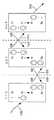
도 6A, 6B 및 6C는 실시예의 온 더 플라이(on-the-fly) 노드 메시지 교환을 도시한 도면이다.
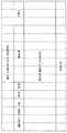
도 7은 실시예의 통신 프로토콜을 도시한 도면이다.
도 8은 실시예의 로봇 수술 시스템에서 동기 정보 및 비동기 정보가 통신되는 방법을 도시한 도면이다.
도 9는 실시예의 로봇 수술 시스템의 네트워크 상의 노드 내외로의 통신을 도시하는 블록도이다.
도 10은 실시예의 로봇 수술 시스템의 통신 네트워크를 도시한 도면이다.
도 11은 실시예의 로봇 수술 시스템의 네트워크 구성 요소의 송신기를 도시한 도면이다.
도 12는 실시예의 로봇 수술 시스템의 네트워크 구성 요소의 수신기를 도시한 도면이다.
도 13은 임의의 실시예의 비가역 등화 노드-분리 가능한 링 와이어링 토폴로지의 도면이다.1 is a view showing an operating room arrangement of the robotic surgical system of the embodiment.
2 is a view showing a robot arm of the embodiment.
3 is a view showing a communication network of the robot surgical system of the embodiment.
4 and 5 are diagrams illustrating an embodiment multi-node message.
6A, 6B and 6C are diagrams illustrating an on-the-fly node message exchange of an embodiment.
7 is a diagram illustrating a communication protocol of an embodiment.
8 is a diagram illustrating a method in which synchronous information and asynchronous information are communicated in the robotic surgical system of the embodiment.
9 is a block diagram showing communication to and from a node on a network of the robotic surgical system of the embodiment.
10 is a view showing a communication network of the robot surgical system of the embodiment.
11 is a view showing a transmitter of a network component of the robotic surgical system of the embodiment.
12 is a diagram showing a receiver of a network component of the robotic surgical system of the embodiment.
13 is a diagram of an irreversible equalization node-separable ring wiring topology of any embodiment.
도입(Introduction)Introduction
다음의 실시예는 제어기와 하나 이상의 로봇 암의 노드 사이에서 정보를 전달하기 위한 링 네트워크를 갖는 로봇 수술 시스템을 설명한다. 로봇 암의 노드와 동기 및 비동기 정보가 통신될 수 있는 통신 프로토콜이 설명된다. 네트워크와 함께 사용될 수 있는 물리 계층의 다양한 양상이 또한 개시된다. 실시예를 살피기 전에, 다음 섹션은 로봇 수술 시스템 및 로봇 암의 예를 제공한다.The following embodiment describes a robotic surgical system having a ring network to transfer information between a controller and a node of one or more robotic arms. A communication protocol in which synchronous and asynchronous information can be communicated with a node of the robot arm is described. Various aspects of the physical layer that can be used with the network are also disclosed. Before looking at the examples, the following sections provide examples of robotic surgical systems and robotic arms.
로봇 수술 시스템의 예Examples of robotic surgical systems
이제 도면을 참조하면, 도 1은 본 기술의 양태에 따른 수술 로봇 시스템(100)을 갖는 예시적인 수술실 환경을 도시한 도면이다. 이는 단지 예시의 목적을 위한 일례일 뿐이며 다른 구성 및 구성 요소가 사용될 수 있음에 유의해야 한다. 따라서, 여기에 제시된 세부 사항 중 어느 것도 명시적으로 언급되지 않는 한 청구 범위로 해석 되어선 안된다.Referring now to the drawings, FIG. 1 is a diagram illustrating an exemplary operating room environment with a
도 1에 도시된 바와 같이, 수술 로봇 시스템(100)은 외과의사용 콘솔(120), 제어 타워(130), 및 수술 로봇 플랫폼(110)(예를 들어, 테이블 또는 베드 등)에 위치된 하나 이상의 수술 로봇 암(112)을 포함하며, 엔드 이펙터를 갖는 수술 도구는 수술 절차를 실행하기 위해 로봇 암(112)의 원위 단부(distal end)에 부착된다. 로봇 암(112)은 테이블 장착 시스템으로 도시되어 있지만, 다른 구성에서, 로봇 암은 카트, 천장 또는 측벽, 또는 다른 적절한 지지 표면에 장착될 수 있다.As shown in FIG. 1, the
일반적으로, 외과의사 또는 다른 조작자와 같은 사용자는 사용자 콘솔(120)을 사용하여 로봇 암(112) 및/또는 수술 기구를 원격으로 조작할 수 있다(예를 들어, 원격 수술(tele-operation)). 사용자 콘솔(120)은 도 1에 도시된 바와 같이 로봇 시스템(100)과 동일한 수술실에 위치 될 수 있다. 다른 환경에서, 사용자 콘솔(120)은 인접한 또는 근처의 방에 위치하거나, 다른 건물, 도시 또는 국가 내의 멀리 떨어진 위치에서 원격 조작될 수 있다. 사용자 콘솔(120)은 좌석(122), 발 조작식 컨트롤(124), 하나 이상의 핸드 헬드 사용자 인터페이스 장치(126), 및 예를 들어 환자 내부의 수술 부위의 뷰를 디스플레이 하도록 구성된 적어도 하나의 사용자 디스플레이(128)를 포함할 수 있다. 예시적인 사용자 콘솔(120)에 도시된 바와 같이, 좌석(122)에 위치하고 사용자 디스플레이(128)를 보는 외과의사는 로봇 암(112) 및/또는 암의 원위 단부에 장착된 수술 기구를 원격으로 제어하기 위해 발 조작식 컨트롤(124) 및/또는 핸드 헬드 사용자 인터페이스 장치(126)를 조작할 수 있다.In general, a user, such as a surgeon or other operator, can remotely manipulate the
일부 변형에서, 사용자는 또한 "베드 위"(OTB) 모드에서 수술 로봇 시스템(100)을 작동시킬 수 있으며, 이 모드에서 사용자는 환자의 측면에 있고 동시에 사용자는 (예를 들어, 핸드 헬드 사용자 인터페이스 장치(126)를 한 손에 들고) 로봇식 구동 도구/그에 부착된 엔드 이펙터 및 수동 복강경 도구를 동시에 조작한다. 예를 들어, 사용자의 왼손은 로봇 수술 구성 요소를 제어하기 위해 핸드 헬드 사용자 인터페이스 장치(126)를 조작할 수 있는 반면, 사용자의 오른손은 수동 복강경 도구를 조작할 수 있다. 따라서, 이러한 변형에서, 사용자는 로봇 보조 최소 침습 수술(MIS) 및 수동 복강경 수술 모두를 환자에게 수행할 수 있다.In some variations, the user can also operate the surgical
예시적인 시술(procedure) 또는 수술 동안, 환자는 마취에 이르기 위해 멸균 상태로 준비되고 드레이프된다. 수술 부위로의 초기 접근은 수술 부위로의 접근을 용이하게 하기 위해 수납된(stawed) 형태 또는 빠져나와 있는(withdrawn) 형태의 로봇 시스템(100)에 의해 수동으로 수행될 수 있다. 접근이 완료되면, 로봇 시스템의 초기 포지셔닝 및/또는 준비가 수행될 수 있다. 시술 동안, 사용자 콘솔(120)의 외과의사는 수술을 수행하기 위해 다양한 엔드 이펙터 및/또는 이미징 시스템을 조작하기 위해 발 조작식 컨트롤(124) 및/또는 사용자 인터페이스 장치(126)를 이용할 수 있다. 멸균 가운을 입은 직원에 의한 수동 보조가 수술 테이블에서 제공될 수도 있으며, 직원은 조직의 당김(retracting) 또는 수동 위치 변경 또는 하나 이상의 로봇 암(112)을 포함하는 도구 교환을 포함하지만 이에 제한되지 않는 작업을 수행할 수 있다. 비 멸균 직원이 또한 외과의사를 보조하기 위해 사용자 콘솔(120)에 존재할 수 있다. 시술 또는 수술이 완료되면, 로봇 시스템(100) 및/또는 사용자 콘솔(120)은, 예를 들어 사용자 콘솔(120)을 통해, 로봇 시스템(100) 세척 및/또는 살균, 및/또는 전자적 또는 하드 카피의 건강 관리 기록 입력 또는 인쇄 출력을 포함하나 이에 제한되지 않는, 하나 이상의 수술 후 절차를 용이하게 하는 상태로 구성 또는 설정될 수 있다.During an exemplary procedure or surgery, the patient is prepared and drape sterile to reach anesthesia. The initial access to the surgical site may be performed manually by the
일부 양태들에서, 로봇 플랫폼(110)과 사용자 콘솔(120) 사이의 통신은 제어 타워(130)를 통해 이루어질 수 있으며, 여기서 제어 타워(130)는 사용자 콘솔(120)로부터의 사용자 명령을 로봇 제어 명령들로 변환하고 로봇 플랫폼(110)으로 전송할 수 있다. 제어 타워(130)는 또한 로봇 플랫폼(110)으로부터의 상태 및 피드백을 사용자 콘솔(120)로 다시 전송할 수 있다. 로봇 플랫폼(110), 사용자 콘솔(120) 및 제어 타워(130) 사이의 연결은 유선 및/또는 무선 연결을 통해 이루어질 수 있으며, 독자 방식(proprietary)이거나 및/또는 다양한 데이터 통신 프로토콜 중 임의의 것을 사용하여 수행될 수 있다. 유선 연결은 선택적으로 수술실의 바닥 및/또는 벽 또는 천장에 설치될 수 있다. 수술 로봇 시스템(100)은 인터넷 또는 다른 네트워크를 통해 액세스 가능한 원격 디스플레이뿐만 아니라 수술실 내의 디스플레이를 포함하는 하나 이상의 디스플레이에 비디오 출력을 제공할 수 있다. 비디오 출력 또는 피드는 또한 프라이버시를 보장하기 위해 암호화될 수 있으며 비디오 출력의 전부 또는 일부는 서버 또는 전자 건강 관리 기록 시스템에 저장될 수 있다.In some aspects, communication between the
도 2는 본 기술의 양태에 따른, 수술 도구가 장착된 로봇 암, 도구 구동부 및 캐뉼라의 하나의 예시적인 설계를 도시한 도면이다. 도 2에 도시된 바와 같이, 예시적인 수술 로봇 암(112)은 복수의 링크 및 그 복수의 링크를 서로에 대해서 작동시키기 위한 복수의 작동식 조인트 모듈을 포함할 수 있다. 조인트 모듈은 피치(pitch) 조인트 또는 롤(roll) 조인트와 같은 다양한 유형을 포함할 수 있으며, 이는 인접 링크의 이동을 다른 링크에 대해 특정 축 주위로 실질적으로 제한할 수 있다. 또한, 도 2의 예시적인 설계에 도시된 바와 같이, 도구 구동부(210)는 로봇 암(112)의 원위 단부에 부착될 수 있다. 도구 구동부(210)는 베이스 또는 스테이지(212) 및 수술 기구(220)(예를 들어, 내시경, 스테이플러 등)를 수용 및 가이드하기 위해 도구 구동부(210)의 단부에 결합된 캐뉼라(214)를 포함할 수 있다. 수술 기구(또는 도구)(220)는 로봇 손목(222) 및 도구의 원위 단부에 하나 이상의 엔드 이펙터(224)를 포함할 수 있다. 로봇 암(112)의 복수의 조인트 모듈은 도구 구동부(210)를 위치시키고 배향시키도록 작동될 수 있으며, 이는 로봇 수술을 위해 로봇 손목(222) 및 하나 이상의 엔드 이펙터(224)를 작동시킨다.2 is a diagram illustrating one exemplary design of a robot arm, tool drive and cannula equipped with a surgical tool, in accordance with aspects of the present technology. As shown in FIG. 2, the exemplary
로봇 암(112)은 또한 인접한 링크들 사이에 복수의 노드를 포함한다. 본 명세서에 사용된 바와 같이, "노드"는 일반적으로 로봇 수술 시스템의 제어기와 통신하는 구성 요소를 지칭할 수 있다. 본 명세서에서 때때로 "조인트 모듈(joint module)"로 지칭될 "노드"는 로봇 암의 하나의 링크를 다른 것에 대해 작동시키기 위해 사용될 수 있다(예를 들어, 모터를 사용하여 일련의 풀리 및 풀리를 연결하는 일련의 밴드를 이동시켜 4바 연결 운동을 가능하게 함). 외부 제어기로부터의 명령에 응답하여(아래에서 더 상세하게 설명됨), 노드는 로봇 암의 다양한 링크를 관절로 연결하여 수술 절차를 위해 암을 조작하는 데 사용될 수 있다.The
노드의 예로는 단일 모터(예를 들어, 서보 모터, 피벗 링크 모터, 조인트 모터 및 공구 구동 모터), 이중 모터(예를 들어, 개별 모터 출력을 결합하기 위한 차동 기어 드라이브 사용), 무선 도구 인터페이스(예를 들어, 도구 무선 보드), 힘/토크 센서(예를 들어, 암 링크/세그먼트 사이에서 로봇 암에 적용되는 힘 및 토크 다방향성 중 적어도 하나를 특징짓는 신호를 검출하고 제공하는 인코더), 입력/출력 보드, 전력 및/또는 통신 링크를 모니터링하는 구성 요소, 또는 데이터를 수신/전송할 수 있는 기타 구성 요소 중 하나 이상을 포함하지만 이에 제한되지는 않는다. 노드는 또한 회로 보드상에 모터 제어기/드라이버, 신호 프로세서 및/또는 통신 전자 기기와 같은 다양한 전자 기기를 포함할 수 있으나 이에 제한되지는 않는다. 아래에서 보다 상세하게 논의되는 바와 같이, 노드는 외부 제어기와 통신하기 위해 링 네트워크로 배치될 수 있다. 일 실시예에서, 로봇 암의 도구의 제어는 무선 도구 인터페이스를 통해 수행되어, 안전상의 이유로 도구와 로봇의 다른 구성 요소 사이에 전기적 절연을 제공한다.Examples of nodes are single motors (e.g. servo motors, pivot link motors, joint motors and tool drive motors), dual motors (e.g. using differential gear drives to combine individual motor outputs), wireless tool interface ( For example, a tool wireless board), a force / torque sensor (e.g., an encoder that detects and provides a signal characterizing at least one of force and torque multidirectional applied to the robot arm between the arm links / segments), input / Output board, components that monitor power and / or communication links, or one or more other components capable of receiving / transmitting data. Nodes may also include, but are not limited to, various electronic devices such as motor controllers / drivers, signal processors and / or communication electronic devices on a circuit board. As discussed in more detail below, nodes can be deployed in a ring network to communicate with external controllers. In one embodiment, control of the tool of the robot arm is performed through a wireless tool interface, providing electrical isolation between the tool and other components of the robot for safety reasons.
로봇 수술 시스템의 통신 네트워크 예Example of communication network of robotic surgical system
도면으로 돌아가면, 도 3은 실시예의 로봇 수술 시스템의 통신 네트워크를 도시한 도면이다. 도 3에 도시된 바와 같이, 이 실시예의 로봇 수술 시스템은 복수의 로봇 암(ARM 1 - ARM n)과 통신하는 베이스 제어기(304)(때로는 "제2 제어기" 라고도 함)와 통신하는 마스터 제어기(302)(때로는 "로봇 제어기" 또는 "데이터 마스터" 또는 간단히 "제어기" 라고 함)를 포함한다. 본 명세서에서 사용되는 바와 같이, "통신하다(in communication with)"라는 문구는 직접 통신하거나 하나 이상의 구성 요소를 통해 간접적으로 통신하는 것을 의미할 수 있으며, 이는 여기에 도시되거나 설명되지 않을 수 있다. 예를 들어, 마스터 제어기(302) 및 베이스 제어기(304)로부터의 신호는 암 링크의 내부 체적 및 로봇 암의 조인트 모듈 내에 번들로 연결된 유선 연결(예를 들어, 와이어 하네스)을 통해 노드에 전달될 수 있다. 또한, 도 3은 복수의 로봇 암을 도시하지만, 로봇 수술 시스템은 단일 로봇 암만을 가질 수 있으며, 이 경우 베이스 제어기(304)는 사용되지 않을 수 있다는 것에 유의해야 한다. 일부 실시예에서 베이스 제어기(304)는 로봇 수술 시스템이 복수의 로봇 암을 갖는 경우에도 사용되지 않는다. 일 실시예에서, 베이스 제어기(304)는 환자 테이블 또는 베드 내에 또는 그 근처에 위치하고(이러한 상황에서, 베이스 제어기(304)는 테이블 어댑터 제어기("TAC")라고 지칭될 수 있다), 마스터 제어기(302)는 환자 베드와 별개의 통신 타워에 위치된다.Returning to the drawing, FIG. 3 is a diagram showing a communication network of the robotic surgical system of the embodiment. As shown in Fig. 3, the robotic surgical system of this embodiment is a master controller communicating with a base controller 304 (sometimes referred to as a "second controller") communicating with a plurality of robot arms (ARM 1-ARM n) 302) (sometimes referred to as a "robot controller" or "data master" or simply "controller"). As used herein, the phrase “in communication with” may mean communicating directly or indirectly through one or more components, which may or may not be illustrated herein. For example, signals from the
임의의 제어기는 임의의 적절한 방식으로 구현될 수 있음에 유의해야 한다. 예를 들어, 제어기는 (마이크로)프로세서, 로직 게이트, 스위치, 주문형 반도체(ASIC), 프로그래머블 로직 제어기 및 임베디드 마이크로 제어기로 실행 가능한 컴퓨터 판독 가능 프로그램 코드(예를 들어, 펌웨어)를 저장하는 처리 회로, 마이크로 프로세서 또는 프로세서, 및 컴퓨터 판독 가능 매체의 형태를 취할 수 있다. 제어기는 하드웨어 및/또는 펌웨어로 구성되어 아래에 설명되고 흐름도에 도시된 다양한 기능을 수행할 수 있다. 보다 일반적으로, 제어기(또는 모듈)는 다양한 동작을 수행하도록 구성된 "회로"를 포함할 수 있다. 본 명세서에서 사용되는 용어 "회로"는 중앙 처리 장치(CPU), 마이크로 제어기 또는 마이크로 프로세서; 또는 주문형 반도체(ASIC), 프로그래머블 로직 디바이스(PLC) 또는 필드 프로그래머블 게이트 어레이(FPGA); 또는 아날로그 회로 구성 요소, 디지털 회로 구성 요소 또는 둘 다를 포함하는 이산 논리 또는 다른 회로 구성 요소의 집합; 또는 이들의 임의의 조합과 같은 명령 프로세서를 지칭할 수 있다. 회로는 예를 들어 별개의 상호 연결된 하드웨어 구성 요소를 포함할 수 있거나, 단일 집적 회로 다이(die) 상에 결합되거나, 다수의 집적 회로 다이 사이에 분산되거나, 또는 공통 패키지에서 다수의 집적 회로 다이의 MCM(Multiple Chip Module)으로 구현될 수 있다. 따라서, "회로"는 실행을 위한 명령어를 저장 또는 액세스 할 수 있거나 하드웨어로만 그 기능을 구현할 수 있다.It should be noted that any controller can be implemented in any suitable way. For example, the controller may include (micro) processor, logic gate, switch, application specific semiconductor (ASIC), programmable logic controller, and processing circuitry that stores computer readable program code (e.g., firmware) executable with an embedded microcontroller, It can take the form of a microprocessor or processor, and a computer readable medium. The controller may consist of hardware and / or firmware to perform various functions described below and shown in a flowchart. More generally, a controller (or module) may include “circuitry” configured to perform various operations. The term "circuit" as used herein refers to a central processing unit (CPU), microcontroller or microprocessor; Or on demand semiconductors (ASICs), programmable logic devices (PLCs) or field programmable gate arrays (FPGAs); Or a set of discrete logic or other circuit components, including analog circuit components, digital circuit components, or both; Or any combination thereof. The circuitry may include, for example, separate interconnected hardware components, coupled on a single integrated circuit die, distributed between multiple integrated circuit dies, or of multiple integrated circuit dies in a common package. It may be implemented as a multiple chip module (MCM). Thus, a "circuit" can store or access instructions for execution or implement its functionality only in hardware.
마스터 제어기(302)는 로봇 암을 조작하기 위해 사용자 콘솔(100)(도 1)로부터 명령을 수신하고 이들 명령을 로봇 암에 전송할 수 있다. 도 3에 도시된 바와 같이, 이 실시예에서, 각각의 로봇 암의 노드는 링 네트워크로 배치된다. 본 명세서에서 사용되는 바와 같이, 링 네트워크는 각 노드가 2 개의 다른 노드에 연결되어 각 노드를 통해 신호에 대한 단일 연속 경로를 형성하는 네트워크 토폴로지를 의미한다. 데이터는 노드에서 노드로 이동하며 그 과정에서 각 노드는 모든 패킷을 처리한다. 특히 로봇 암의 원위 단부에 있는 노드의 경우 전파 지연이 밸런싱될 수 있다. 도 3은 각각의 로봇 암이 동일한 수의 노드를 갖는 것을 도시하지만, 다른 실시예에서, 적어도 하나의 로봇 암은 시스템의 다른 로봇 암과 다른 수의 노드를 갖는다. 아래에서 보다 상세하게 설명되는 바와 같이, 링 네트워크는 로봇 암 네트워크를 통해 실시간 및 비동기 정보 모두를 통신하는데 사용될 수 있다.The
마스터 제어기(302)는 복수의 패킷을 포함하는 다중 노드 메시지를 사용하여 특정 로봇 암의 복수의 노드와 통신하도록 구성되며, 각각의 패킷은 로봇 암의 상이한 노드와 연관된다. 암 다중 노드 메시지는 해당 암의 모든 노드에 대한 데이터를 포함할 수 있다는 점에서 "다중 노드(multi-node)"이다. 패킷은 임의의 적절한 방식으로 노드와 연관될 수 있다. 예를 들어, 각각의 패킷은 로봇 암의 다른 노드(예를 들어, 노드의 식별자를 사용하여)로 어드레싱 될 수 있고/있거나 노드는 메시지의 특정 패킷 위치와 연관될 수 있다. 물론, 이것은 단지 예시일 뿐이며, 다른 연관도 사용될 수 있다.The
다중 노드 메시지의 각 패킷은 임의의 적절한 방식으로 포맷될 수 있다. 예를 들어, 도 4에 도시된 바와 같이, 일 실시예에서, 다중 노드 메시지의 패킷은 헤더, 데이터 페이로드 및 순환 중복 검사(CRC) 필드를 포함할 수 있다. 도 5에 도시된 다른 실시예에서, 패킷은 16 비트 패킷 프레이밍 상수, 16 비트 헤더, 사이 클릭 데이터(명령 또는 피드백) 비사이클릭, 및 비동기 데이터를 포함하는 고정 크기(예를 들어, 128 비트 또는 224 비트) 데이터 페이로드, 및 16 비트 CRC 필드(예를 들어, CCITT)를 포함한다. 패킷 프레이밍 상수는 패킷의 시작을 확인하는 데 사용될 수 있다. 페이로드 데이터 유형은 데이터 페이로드의 형식을 결정하는 데 사용될 수 있다(예를 들어, 모터 명령, 모터 피드백, 디지털 입력, 디지털 출력 및 힘 피드백). 채널 ID는 노드가 패킷이 해당 노드로 전달되도록 의도된 것임을 확인하기 위해 노드에서 사용할 수 있다(일 실시예에서, 모든 로봇 암에 걸친 모든 노드는 고유한 채널 ID를 갖는다). 시퀀스 필드는 노드가 패킷이 새로운 것인지 아닌지를 결정하는 것을 돕는다. 마스터 제어기(302)는 새로운 패킷을 전송할 때마다 시퀀스 번호를 증가시킨다. 마스터 제어기(302)가 인터럽트되면, 노드는 동일한 시퀀스 번호를 두 번 관측하고 그것이 중복 패킷임을 알 수 있다. CRC 필드는 전체 패킷을 커버할 수 있다. 일 실시예에서, 프레임 당 80개의 패킷이 있으며, 각 프레임은 동일한 크기이다. 물론 이것은 하나의 예일 뿐이며 다른 구성을 사용할 수 있다.Each packet of a multi-node message can be formatted in any suitable way. For example, as shown in FIG. 4, in one embodiment, a packet of a multi-node message may include a header, data payload, and cyclic redundancy check (CRC) fields. In another embodiment shown in Figure 5, the packet is a fixed size (e.g., 128 bit or 16 bit packet framing constant, 16 bit header, cyclic data (command or feedback) acyclic, and asynchronous data). 224 bits) data payload, and a 16-bit CRC field (eg, CCITT). The packet framing constant can be used to confirm the start of a packet. The payload data type can be used to determine the format of the data payload (eg, motor command, motor feedback, digital input, digital output and force feedback). The channel ID can be used by the node to verify that the node is intended to forward packets to that node (in one embodiment, all nodes across all robot arms have a unique channel ID). The sequence field helps the node determine whether the packet is new or not. The
하나의 로봇 암만이 사용된다면, 마스터 제어기(302)는 다중 노드 메시지를 그 암에 직접 전송할 수 있다. 다수의 로봇 암이 사용되는 경우, 마스터 제어기(302)는 모든 암에 대한 모든 다중 노드 메시지를 단일 메시지로 함께 베이스 제어기(304)에 전송할 수 있다. 베이스 제어기(304)는 단일 메시지로부터 각각의 개별 다중 노드 메시지를 분리해 내고 각각의 로봇 암에 연관된 개별 다중 노드 메시지를 전송할 수 있다. 예를 들어, 베이스 제어기(304)는 전체 결합 메시지에서 메시지의 오프셋에 기초하여 메시지를 서로 다른 로봇 암에 라우팅 할 수 있다.If only one robot arm is used, the
다중 노드 메시지가 링을 통과하고 베이스 제어기(304)로 리턴한 후, 베이스 제어기(304)는 수신된 개별 다중 노드 메시지를 단일의 리턴된 병합된 메시지로 결합하고, 단일의 리턴된 병합된 메시지를 마스터 제어기(302)에 전송할 수 있다. 베이스 제어기(304)는 다른 기능을 수행하도록 구성될 수 있다. 예를 들어, 마스터 제어기(302)가 시스템에 연결되지 않은 경우(예를 들어, 간호사가 환자를 드레이프하기 전에 로봇 암을 밖으로 움직일 수 있도록 허용) 베이스 제어기(304)는 로봇 암을 이동시키는 데 사용될 수 있다.After the multi-node message passes through the ring and returns to the
위에서 언급한 바와 같이, 다중 노드 메시지는 특정 암의 노드와 통신하는 데 사용된다. 다중 노드 메시지는 k 개의 박스카가 있는 열차와 유사하며, 암의 각 노드에는 박스카가 할당되고, 승객(데이터 페이로드)은 지정된 박스카를 승하차한다(즉, 전 양방 방식(full-duplex)). 마스터 제어기(302)는 사이클 당 하나 이상의 다중 노드 메시지를 스케줄링 할 수 있고, 각 메시지의 타이밍은 분산 된 디지털 샘플링 시스템의 최적 제어를 위해 최적화 될 수 있다.As mentioned above, multi-node messages are used to communicate with nodes of a particular arm. The multi-node message is similar to a train with k box cars, each node of the arm is assigned a box car, and the passenger (data payload) gets on and off the designated box car (i.e., full-duplex). The
도 6A, 6B 및 6C는 이러한 통신 흐름을 도시한다. 이들 도면에 도시된 바와 같이, 노드는 다중 노드 메시지를 처리하고 노드와 링 네트워크 간의 물리적 인터페이스인 필드-프로그래머블 게이트 어레이(FPGA)를 포함할 수 있다. 일 실시예에서, FPGA 및 노드 제어기는 직렬 주변 장치 인터페이스(SPI) 버스를 통해 통신한다. 도면을 단순화하기 위해 도시되지 않았으나, 노드는 노드 제어기에 연결된 모터 또는 센서와 같은 하나 이상의 추가 구성 요소를 가질 수 있다.6A, 6B and 6C illustrate this communication flow. As shown in these figures, a node can process multi-node messages and include a field-programmable gate array (FPGA), which is a physical interface between the node and the ring network. In one embodiment, the FPGA and node controller communicate over a serial peripheral interface (SPI) bus. Although not shown to simplify the drawing, a node may have one or more additional components, such as motors or sensors, connected to a node controller.
동작 중에, FPGA는 다중 노드 메시지를 디코딩하고, 동기 토큰을 찾고, 메시지에서 어떤 패킷이 그 노드와 연관되어 있는지를 결정한다. 그런 다음 메시지 패킷에서 데이터를 교환할 수 있다. 예를 들어, 도 6a 및 6b에 도시된 바와 같이, FPGA는 메시지를 수신한 후, 특정 패킷이 자신의 노드와 연관되어 있다고 FPGA가 판단할 때까지 메시지 패킷을 통과시킨다. 도 6c에 도시된 바와 같이, 그 때, FPGA는 패킷으로부터 노드 제어기의 메모리로 데이터를 복사하고 노드 제어기의 메모리에 저장된 다른 데이터로 교환할 수 있다. 교환되는 데이터는 노드 제어기에서 미리 준비할 수 있으므로, 적절한 패킷이 도착하면 바로 전송할 수 있다. 이 실시예에서, SPI 버스는 자동 교환을 수행하는 프로토콜을 사용하고, FPGA는 데이터를 패킷 밖으로 또는 패킷으로 이동시키는 데 있어서의 동기화 문제를 해결하기 위해 약간의 지연을 가진 프로그래밍일 수 있다. 이로 인한 실질 효과는 각 노드가 다른 노드와 동시에 패킷을 수신하고 응답하기 때문에 각 노드에 의해 유발되는 대기 시간이 거의 없다는 것이다(즉, 각 노드는 전체 다중 노드 메시지를 수신하지 않고 응답을 보낸다).In operation, the FPGA decodes the multi-node message, finds a sync token, and determines which packets in the message are associated with that node. You can then exchange data in message packets. For example, as shown in FIGS. 6A and 6B, after receiving the message, the FPGA passes the message packet until the FPGA determines that a particular packet is associated with its node. As shown in FIG. 6C, at that time, the FPGA can copy data from the packet to the node controller's memory and exchange it for other data stored in the node controller's memory. The exchanged data can be prepared in advance by the node controller, and can be transmitted immediately when an appropriate packet arrives. In this embodiment, the SPI bus uses a protocol to perform automatic exchanges, and the FPGA can be programming with some delay to solve the synchronization problem in moving data out of or into packets. The real effect of this is that each node receives and responds to packets simultaneously with other nodes, so there is little latency caused by each node (i.e., each node sends a response without receiving a full multi-node message).
일 실시예에서, 기본적으로, 다중 노드 메시지의 모든 메시지는 변경되지 않은 임의의 노드를 통과한다. 노드는 프레임 동기 토큰과 프로그래밍된 메시지 길이에 관련하여 프로그래밍된 시작값에 기초하여 특정 메시지만 추출하고 대체하도록 프로그래밍되어 있다. 이것은 열차 내에서 특정 철도 차량(또는 프레임당 2개의 교환이 있기 때문에 오히려 2개)에 노드가 할당되는 것과 유사하다. 노드가 n 개인 경우 2n 개의 차량이 있고 노드 x에 차량 x 및 x + n이 할당된다. 일 실시예에서, 각각의 노드는 할당된 시간에 데이터를 교환해야 하고, 그렇게 하는 것을 실패하면 시스템 결함이다(다른 구현이 가능). 사용 가능한 새 데이터가 없어도 노드는 올바른 형식의 응답 패킷을 생성해야 할 수 있다. 언급한 바와 같이, 프레임당 2개의 데이터 교환이 있으며, 각각 동기식 명령/비동기식 응답 및 비동기식 명령/동기식 응답을 전달한다. 데이터 교환은 전적으로 동기 토큰에 대한 메시지의 위치에 기초한다. 메시지 자체에 대한 해석은 메시지 사이의 시간 동안 프로세서 내부에서 이루어진다. 마찬가지로, 모든 응답은 전송 시간 슬롯이 도착하기 전에 노드에 의해 준비된다. 노드는 이를 위해 필요한 타이밍을 충족시킬 수 있는지 확인해야 한다.In one embodiment, by default, all messages of a multi-node message go through any node that has not changed. The node is programmed to extract and replace only specific messages based on the frame sync token and the programmed start value in relation to the programmed message length. This is analogous to the assignment of nodes to specific rail vehicles (or rather 2 because there are 2 exchanges per frame) within the train. If there are n nodes, there are 2n vehicles and nodes x are assigned vehicles x and x + n. In one embodiment, each node must exchange data at the allotted time, and failing to do so is a system fault (other implementations are possible). A node may need to generate a properly formatted response packet even if there is no new data available. As mentioned, there are two data exchanges per frame, each carrying synchronous command / asynchronous response and asynchronous command / synchronous response. Data exchange is based entirely on the location of the message relative to the sync token. Interpretation of the message itself takes place inside the processor during the time between messages. Likewise, all responses are prepared by the node before the transmission time slot arrives. Nodes need to make sure they can meet the timing required for this.
로봇 암의 노드와 동기 및 비동기 정보를 통신하는 예Example of communicating synchronous and asynchronous information with a node of a robot arm
일 실시예에서, 마스터 제어기(302)와 로봇 암의 노드 사이에서 통신될 정보는 일반적으로 "동기 정보" 또는 "비동기 정보"로 분류될 수 있다. 본 명세서에서 사용되는 "동기 정보"는 수신시 또는 특정 시간 프레임 내에서(실시간으로) 처리되도록 의도된 정보를 지칭하는 반면, "비동기 정보"는 저장 및 나중에 처리될 수 있는 정보(특정 시간 프레임 내에 처리될 필요가 없음)를 의미한다. 따라서 동기 정보와 비교하여 비동기 정보가 수신될 때와 처리될 때 사이에 약간의 대기 시간이 있을 수 있다. 예를 들어, 외과의사는 로봇 암이 움직임을 지시한 후 즉시 움직일 것을 기대하기 때문에 모터를 작동시키는 명령은 동기 정보로 분류될 수 있다. 따라서 특정 시간 프레임 내에 명령을 수행해야 한다. 대조적으로, 우선 순위가 낮은 유지 보수 기능을 수행하는 명령은 명령이 엄격한 시간 프레임에서 수행될 필요가 없고 노드가 시간을 낼 수 있을 때마다 수행될 수 있기 때문에 비동기로 분류될 수 있다.In one embodiment, the information to be communicated between the
일 실시예에서, 마스터 제어기(302)와 로봇 암의 노드 사이의 전송 타이밍은 전달되는 정보가 동기 정보인지 비동기 정보인지에 관계없이 동일하다. 따라서, 동기 정보와 비동기 정보는 이 실시예에서 동일한 전송 동시성을 갖기 때문에, "동기" 및 "비동기"는 전송 레벨의 타이밍 요구 사항이 아니라 프로토콜 레벨의 정보 유형(즉, 명령을 실시간으로 처리해야 하는지 여부)을 지칭한다. 일 실시예에서, 타이밍과 관련하여 비동기와 동기의 유일한 차이점은 프레임 내 배치로 인해 동기가 지연이 약간 더 낮다는 것이다.In one embodiment, the transmission timing between the
임의의 적절한 유형의 동기 정보 및 비동기 정보가 사용될 수 있고 명령(때로는 "요청"으로 지칭됨) 및 명령에 대한 응답의 형태를 취할 수 있다. 예를 들어, 동기 명령은 노드에 전송되는 명령으로서, 그 노드에 의해 처리/실행될 때 로봇 암의 링크를 특정 위치로 이동시키거나 특정 토크를 가하기 위해 모터를 작동시키는 명령(즉, 실시간 모터 제어 명령)일 수 있다. 노드로부터 동기 명령에 대한 응답은 그 명령에 대한 피드백일 수 있다(예를 들어, 요청된 움직임이 실제로 발생했는지 확인하기 위해 노드의 힘/토크 센서로부터의 판독). 비동기 명령은 노드로부터의 정보를 요청하기 위해(예를 들어, 로봇 암에 연결된 수술 도구의 식별(identification) 및 교정 및 운동학적 매개 변수에 대한 정보), 감독/하우스 키핑 기능 수행을 요청하기 위해(예를 들어, 노드의 온도 및 전압 측정), 또는 노드의 매개변수 중 하나에 대한 변경을 요청하기 위해 노드로 전송되는 명령일 수 있다.Any suitable type of synchronous and asynchronous information can be used and can take the form of commands (sometimes referred to as "requests") and responses to commands. For example, a synchronous command is a command transmitted to a node, and when processed / executed by the node, a command to move the link of the robot arm to a specific position or to operate the motor to apply a specific torque (ie, a real-time motor control command) ). The response to the synchronous command from the node can be feedback to the command (eg, reading from the node's force / torque sensor to see if the requested movement actually occurred). Asynchronous commands may request information from a node (e.g., identification of surgical instruments connected to a robotic arm and information about corrective and kinematic parameters), and request to perform supervision / housekeeping functions ( For example, it may be a command sent to a node to request a change to one of the node's parameters), or measurement of the node's temperature and voltage.
전술한 바와 같이, 일 실시예에서, 마스터 제어기(302)와 로봇 암의 노드 사이의 전송 타이밍은 전달되는 정보가 동기 정보인지 비동기 정보인지에 관계없이 동일하다. 다음의 단락들은 실시간 네트워크상에서 동기 정보 또는 비동기 정보를 스케쥴링 하는데 사용될 수 있는 실시예의 프로토콜을 설명한다. 이 실시간 프로토콜은 예를 들어, 마스터 제어기(302)와 로봇 암의 노드의 분산 모터 제어기 사이의 데이터 전송 및 데이터 시퀀스를 규정하는데 사용될 수 있다. 이러한 프로토콜을 사용하면 가볍고 결정성 있는 통신 시스템을 로봇 플랫폼에 긴밀하게 통합하여 강력하고 지속 가능한 설계를 제공할 수 있다.As described above, in one embodiment, the transmission timing between the
일반적으로, 본 실시예의 통신 프로토콜은 정적으로 할당된 대역폭 및 상이한 유형의 동기 및 비동기 정보 사이에서 대역폭을 공유하기 위한 간단한 스케줄을 사용하여 동기 및 비동기 정보의 실시간 등시성 데이터 통신을 제공한다. 일 실시예에서, 통신 프로토콜은 마스터 제어기(302)와 로봇 암의 복수의 노드 사이의 강력하고 등시적인 실시간 데이터 전송을 지원하기 위해 일정한 사이클 시간을 사용한다. (본 명세서에서 사용되는 바와 같이, 사이클은 마스터 제어기(302)가 하나 이상의 다중 노드 메시지를 링 네트워크에 전송할 때부터 그 메시지를 링 네트워크로부터 수신할 때까지의 시간을 지칭할 수 있다.) 임의의 적합한 사이클 시간이 사용될 수 있지만, 일 실시예에서, 사이클 시간은 최소 레이턴시(latency) 및 최소 지터로(jitter) 모션 제어 업데이트 속도를 제공할 수 있는 고주파수(예를 들어, 4 kHz)에 있다. 아래에서 더 상세히 논의되는 바와 같이, 일 실시예에서, 데이터 패킷의 페이로드는 동기 명령(예를 들어, 모터 제어 명령), 비동기 명령, 동기 명령에 대한 응답(예를 들어, 센서 피드백) 및 비동기 명령에 대한 응답 사이에서 번갈아 나타난다. 이 실시예에서, 데이터의 각 카테고리는 전체 대역폭의 고정된 부분을 수신하고 다른 카테고리의 데이터와 동일한 우선 순위로 제공된다.Generally, the communication protocol of this embodiment provides real-time isochronous data communication of synchronous and asynchronous information using a statically allocated bandwidth and a simple schedule for sharing bandwidth between different types of synchronous and asynchronous information. In one embodiment, the communication protocol uses a constant cycle time to support powerful and isochronous real-time data transmission between the
전술한 바와 같이, 일 실시예에서, 통신을 위한 강력한 데드 라인(hard deadline)으로 등시성 실시간 데이터 전송을 지원하기 위해 사이클 시간은 일정하고(명목상 250 마이크로 초), 2개의 데이터 프레임이 각 사이클마다 교환된다. 이는 도 7에 도시되어 있다. 도 7에 도시된 바와 같이, 특정 사이클에서, 마스터 제어기(302)와 로봇 암의 노드 사이에 2 개의 데이터 프레임이 전송되고 있다. 동시에, 마스터 제어기(302)는 다음 명령 사이클에서 어떤 명령을 발행할지를 결정하기 위해 로봇 제어 알고리즘을 실행하고 있다. 예를 들어, 제1 통신 사이클에서, 왼쪽에서 오른쪽으로의 도 7의 중심선을 보면, 마스터 제어기(302)는 프레임 B를 수신하는데, 이는 이 예에서는 모든 암에서 모터 제어기로 오는 센서 데이터를 포함한다(즉, 이전에 노드가 수신한 동기 명령에 대한 응답). 제2 통신 사이클에서, 마스터 제어기(302)는 그 센서 데이터를 사용하여 다음 통신 사이클에서 노드에 전송할 명령을 결정한다. 예를 들어, 센서 피드백이 로봇 암이 의도된 위치에 있지 않다는 것을 나타내면, 마스터 제어기(302)는 해당 노드의 위치를 수정하기 위해 다른 모터 명령이 필요한지 결정할 수 있다. 제 3 통신 사이클에서, 마스터 제어기(302)는 이전 사이클에서 로봇 제어 알고리즘에서 결정된 명령을 포함하는 프레임 A를 노드로 전송한다. 따라서 이 통신 프로토콜은 파이프 라이닝(pipelining) 및 스테이징(staging)을 사용한다. 이와 같이, 동작은 시간이 겹치며 피드백이 수신될 때부터 새로운 명령이 전송될 때까지 일정 시간의 대기 시간이 있다.As described above, in one embodiment, the cycle time is constant (nominal 250 microseconds) to support isochronous real-time data transmission as a hard deadline for communication, and two data frames are exchanged for each cycle do. This is illustrated in FIG. 7. As shown in Fig. 7, in a specific cycle, two data frames are being transmitted between the
이제 도 8을 참조하면, 도 8은 사이클의 두 프레임이 마스터 제어기(302)(이 예에서는 "로봇 제어기"라고 함)와 노드(이 예에서의 모터 제어기)사이의 동기 정보를 통신하는 데 어떻게 사용될 수 있는지를 보여준다. 도 8에 도시된 바와 같이, 사이클의 한 부분(프레임 A) 동안, 동기 명령(예를 들어, 모터 명령)은 마스터/로봇 제어기(102)로부터 각 노드(예를 들어, 모터 제어기)로 전송되고 이전 사이클에서 수신된 비동기 명령에 대한 응답은 각 노드로부터 마스터/로봇 제어기(302)로 전송된다. 사이클의 다른 부분(프레임 B) 동안, 이전 사이클에서 수신된 동기 명령에 대한 응답(예를 들어, 모터 제어 명령에 대한 모터 피드백)이 각 노드로부터 마스터/로봇 제어기(302)로 전송되고, 비동기 명령들이 마스터/로봇 제어기(302)로부터 각각의 노드로 전송된다. 따라서, 모든 프레임에서, 비동기 정보는 동기 정보와 인터리빙(interleave)된다. 즉, 각 프레임에 대해 대역폭의 절반은 비동기 정보로 사용되고 나머지 절반은 동기 정보로 사용된다.Referring now to FIG. 8, FIG. 8 shows how two frames of a cycle communicate synchronization information between a master controller 302 (in this example referred to as a “robot controller”) and a node (the motor controller in this example). Shows whether it can be used. As shown in FIG. 8, during a portion of the cycle (frame A), a synchronous command (eg, motor command) is sent from the master / robot controller 102 to each node (eg, motor controller). The response to the asynchronous command received in the previous cycle is sent from each node to the master /
전술한 바와 같이, 동기 정보가 실시간으로 처리되는 동안, 비동기 정보(명령 또는 응답)가 저장되고 나중에 처리될 수 있다. 비동기 정보가 실시간으로 소비되지 않을 수 있으므로, 도 8은 마스터/로봇 제어기(402) 및 노드(예를 들어 모터 제어기)가 전송 또는 처리될 비동기 명령(요청) 및 응답을 대기시키기 위한 적어도 하나의 메모리를 가질 수 있음을 도시한다. 이러한 방식으로 대기열은 비동기 도메인에서 발생하는 것과 실시간 네트워크에서 발생하는 것 사이에 버퍼를 만든다. 예를 들어, 마스터/로봇 제어기(402)는 비동기 하우스 키핑 명령을 생성하고 이를 노드로 전송할 기회가 있을 때까지 비동기 요청 대기열에 저장할 수 있다. 마찬가지로, 노드는 비동기 하우스 키핑 명령을 대기열에 저장하고 노드가 기회가 있을 때 이를 처리할 수 있다. 노드와 마스터/로봇 제어기(302)의 동일한 대기열 프로세스는 노드가 마스터/로봇 제어기(302)에 비동기식 응답을 전송할 때 발생할 수 있다. 그러나 도 8의 단일 상자로 도시되듯이, 동기 명령/응답은 실시간으로 전송 및 실행된다(즉, 나중에 전송 및 실행하기 위해 저장되지 않음).As described above, while the synchronization information is processed in real time, asynchronous information (command or response) can be stored and processed later. As asynchronous information may not be consumed in real time, FIG. 8 shows at least one memory for waiting for an asynchronous command (request) and response to be transmitted or processed by the master / robot controller 402 and a node (for example, a motor controller). It can be shown that can have. In this way, the queue creates a buffer between what happens in the asynchronous domain and what happens in the real-time network. For example, the master / robot controller 402 can generate an asynchronous housekeeping command and store it in the asynchronous request queue until there is a chance to send it to the node. Likewise, a node can queue an asynchronous housekeeping instruction and process it when the node has a chance. The same queuing process of the node and the master /
도 7 및 도 8을 다시 참조하면, 일 실시예에서, 로봇 제어 알고리즘은 다음 사이클(N+1)의 다음 동기 명령이 무엇이여야 하는지 (사이클 N에서) 결정하므로 로봇 제어 알고리즘이 최신 정보를 갖도록 동기 피드백은 가능한 한 사이클(사이클 N-1)에서 늦게 발생한다. 또한, 일 실시예에서, 동기 명령은 해당 노드에 도달하여 가능한 빨리 실행될 수 있도록 동기 명령은 가능한 빨리 사이클 N + 1에서 전송된다.Referring again to FIGS. 7 and 8, in one embodiment, the robot control algorithm determines what the next sync command of the next cycle (N + 1) should be (in cycle N), so that the robot control algorithm is synchronized to have the latest information. Feedback occurs as late as possible in the cycle (cycle N-1). In addition, in one embodiment, the synchronous command is transmitted in cycle N + 1 as soon as possible so that the synchronous command reaches the node and can be executed as soon as possible.
로봇 수술 시스템의 통신 네트워크의 물리 계층의 예Example of the physical layer of the communication network of a robotic surgical system
네트워크에서 임의의 적절한 물리 계층이 사용될 수 있다. 일 실시예에서, 베이스 제어기(304)와 로봇 암의 노드 사이의 통신은 추가적인 저속 양방향(bi-directional) 공통 모드 통신 능력을 갖는 의사(pseudo)-저전압 차동 시그널링(LVDS)을 갖는 트위스트-페어(twisted-pair) 구리 케이블을 사용한다. 단일 케이블을 사용하여 모든 노드를 베이스 제어기(304)에 연결하는 대신, 가장 긴 케이블 길이를 최소화하기 위해, 각 구성 요소 사이에 짧은 케이블을 사용할 수 있다. 이러한 특정은 도 9에 다이어그램으로 표시된다.Any suitable physical layer can be used in the network. In one embodiment, communication between the
마스터 제어기(302)와 베이스 제어기(304) 사이의 통신은 전기 절연 및 낮은 전자기 간섭을 달성하기 위해 광섬유 링크를 사용할 수 있다. 일례의 구현에서, 1000BASE-SX 이더넷과 호환되는 광섬유 링크가 사용된다. 그러나 이 링크는 이더넷 패킷을 전달하지 않고 1.25Gbps 원시 비트 전송률을 가진 오로라(Aurora) 인터페이스를 사용한다. 이 구현은 다른 유형의 솔루션에 이점을 제공할 수 있다. 예를 들어, 제어기 영역 네트워크(CAN)는 특정 요구 사항(예를 들어, 1M 비트/초, 400Hz 사이클 속도)에 비해 너무 느릴 수 있고, 이더넷은 실시간 통신에 적합하지 않으며 너무 크고 무겁고, 및 제어 자동화 기술(EtherCAT)용 이더넷은, 강력한 실시간 애플리케이션을 지원하지만, 일부 애플리케이션에 대해 너무 크고 비용이 많이 드는 솔루션일 수 있다.Communication between the
상술한 바와 같이, 가장 긴 케이블 길이를 최소화하기 위해, 단일 케이블을 사용하여 모든 노드를 베이스 제어기(304)에 연결하는 대신, 짧은 케이블을 각 구성 요소 사이에 사용할 수 있다. 다음 단락에서는 노드 간 길이를 균등화하고 개별 노드를 쉽게 교체할 수 있으며 (선택적으로)역 접속을 허용하지 않는 링 토폴로지에 대해 설명한다.As described above, instead of connecting all nodes to the
실시간 제어를 위해서는 높은 속도의 버스가 바람직하다. 그러나 기계적으로 선형 방식인 링 토폴로지는 일반적으로 노드 간 짧은 홉(hop)과 긴 리턴 경로를 가지므로, 버스의 최대 속도가 줄어든다. 긴 리턴은 또한 노이즈에 더 민감하다. 각 노드에 두 개의 커넥터를 갖는 것은 또한 전송 케이블과 수신 케이블을 반대로 연결하는 것을 초래하는데, 이는 이상적이지 않다. 노드 스킵(node-skipping) 구성의 일반적인 와이어링은 각 노드에서 종료되지 않은 와이어를 가지고 있으며, 노드를 교체하려면 두 개의 인접 노드를 분리해야 한다.For real-time control, a high-speed bus is desirable. However, the mechanically linear ring topology generally has short hops and long return paths between nodes, thus reducing the maximum speed of the bus. Long returns are also more sensitive to noise. Having two connectors on each node also leads to the reverse connection of the transmission cable and the reception cable, which is not ideal. Typical wiring in a node-skipping configuration has unterminated wires at each node, and replacing two nodes requires the separation of two adjacent nodes.
각 노드 간의 거리를 동일하게 하면 버스 속도가 높아지고 노이즈가 분산된다. 각 노드에는 두 개의 가시적인 통신 케이블이 있으므로, 각 노드가 연결되는 위치를 아는 것이 제조 및 문제 해결 관점에서 유리하다. 노드 스킵 구성의 일반적인 와이어링은 각 노드에서 종료되지 않은 와이어를 가질 수 있다. 노드를 교체하려면 인접한 두 노드를 분해해야 한다. 통과단(pass-through)에서의 종료가 이 문제를 해결한다.Equal distance between nodes increases bus speed and disperses noise. Since each node has two visible communication cables, knowing where each node is connected is advantageous from a manufacturing and troubleshooting perspective. Typical wiring in a node skip configuration may have unterminated wires at each node. To replace a node, you must disassemble the two adjacent nodes. Termination at the pass-through solves this problem.
도 13을 참조하면, 일 실시예에서, 각각의 노드는 통과 케이블 커넥터 및 활성 케이블 커넥터를 가지며, 이는 노드 스킵 구성을 제공하는데 사용될 수 있다. 보다 구체적으로, 일 실시예에서, 각각의 노드는 크로스오버(핀 1은 핀 4에, 핀 2는 핀 3에 연결됨, 등)로 연결된 2 개의 고유한 커넥터 케이블을 갖는다. 일 구현에서, 하나의 케이블은 4 핀 대 4 핀이고 다른 하나는 5 핀 대 5 핀이다. 이 두 가지 다른 커넥터를 사용하면 연결이 반대로 되지 않는다. 4 핀 케이블은 통과단을 연결하여 인접한 노드에서 신호를 수신한다. 5 핀은 인접한 노드의 통과단에 연결된다. 통과단은 각 노드에 대해 로컬이다. 따라서 각 노드는 통과 케이블 커넥터와 활성 케이블 커넥터를 포함하며, 이를 통해 케이블은 노드 스킵 구성을 제공하기 위해 통과 지점 케이블 커넥터 및 활성 케이블 커넥터에 연결될 수 있다. 이는 도 13에 도시되어 있다. 도 13에 도시된 바와 같이, 화살표(1300)는 링의 증가하는 노드 번호 부분을 나타내고, 화살표(1310)는 노드 3으로부터의 송신, 노드 4의 통과 및 노드 5에 의한 수신을 나타낸다. 화살표(1320)은 링의 감소하는 노드 번호 부분을 나타내며 여기서 노드 4로부터의 송신 신호는 노드 3을 통과하고 노드 2에 의해 수신된다. 이는 노드의 절반은 나가는 과정에 활성이며, 나머지 절반은 돌아오는 과정에 활성인 "아웃 앤드 백(out and back)"으로 생각할 수 있다.13, in one embodiment, each node has a through cable connector and an active cable connector, which can be used to provide a node skip configuration. More specifically, in one embodiment, each node has two unique connector cables connected by a crossover (
루프백(loopback)은 마지막 노드에서 로컬이거나 마지막 노드의 외부 루프백 케이블을 통해 가능하다. 일 실시예에서, 마지막 노드는 선형 레이아웃에서 물리적으로 마지막 노드일 뿐이며; 실제로 데이터 플로우 레이아웃에서 n/2 노드이다. 첫 번째 노드 또는 "마스터"는 루프백 없이 송수신 할 수 있다.Loopback can be local to the last node or through the outer node's external loopback cable. In one embodiment, the last node is only the physically last node in a linear layout; It is actually an n / 2 node in the data flow layout. The first node or "master" can send and receive without loopback.
또한, 일 실시예에서, 베이스 제어기(304)는 노드와의 통신을 위한 타이밍 마스터이다. 이것은 실시예의 링 네트워크의 다른 도면인 도 10과 관련하여 논의될 것이다. 위에서 논의된 바와 같이, 베이스 제어기(304)는 단일 메시지로부터 각각의 개별 다중 노드 메시지로 분리할 수 있고, 각각의 로봇 암에 연관된 개별 다중 노드 메시지를 동시에 전송할 수 있다. 이 실시예에서, 기본 제어기(304)는 노드로의 통신 타이밍을 담당하고, 이로 인해 동시 통신이 이루어 진다. 예를 들어, 도 9에 도시된 바와 같이,

일 실시예에서, 다양한 다중 노드 암 메시지를 분리하는 것 외에, 베이스 제어기(304)는 통신의 타이밍 및 스케줄링을 담당한다. 베이스 제어기(304)는 4KHz 프레임을 생성할 수 있고 언제 로봇 암과 메시지를 주고 받을지 알기 때문에 (예를 들어, 메시지가 동시에 노드에서 전송/수신된다) "타이밍 마스터(timing master)"이다. 예를 들어, 도 10에 도시된 바와 같이, 하나의 사이클(T)에서


도 11 및 12는 베이스 제어기(304)와 로봇 암의 노드 사이의 물리적 네트워크 상에서 통신하는데 사용될 수 있는 송신기 및 수신기의 도면이다. 이것은 단지 하나의 예일 뿐이며, 다른 구성이 사용될 수 있음에 유의해야 한다. 도 11에서 송신기를 먼저 살피면, 본 실시예의 송신기는 발신 신호가 LVDS와 호환 가능하지만 종래의 LVDS 송신기에 의해 전송되지 않는다는 점에서 "의사(pseudo)-LVDS" 송신기이다. 여기에는 몇 가지 이유가 있다. 예를 들어, LVDS는 공통 모드에서 일반적으로 약 1.25 볼트이며 0과 1을 전송하기 위해 수백 밀리볼트를 올리거나 내린다. 이 실시예의 송신기는 외부 저항 분배기를 통해 동일한 신호 레벨링을 생성한다. 하나의 입력을 하이로 구동하고 다른 입력을 로우로 구동하면 LVDS 호환 신호가 발생한다. 두 입력을 모두 하이 또는 로우로 구동하면 각각 3.3V 및 0V의 공통 모드에서의 출력이 로우가 되며 이는 추가 정보(예를 들어, 전력 공급 시퀀싱 및 링 네트워크를 초기화하기 위한 2차 저속 통신 채널)를 인코딩하는데 사용할 수 있다. 이 의사-LVDS 송신기를 사용하는 또 다른 이유는 백-터미네이션(back-terminated) 전송 라인을 제공하는 것이므로 라인에 노이즈가 있으면 지연 시간이 절반으로 줄어들고 앞뒤로 왕복할 필요가 없다. 구체적으로, 이 실시예에서, 3.3V LVCMOS 출력은 저항 네트워크를 통해 배선되어 백-터미네이션 된 100 옴(Ohm) 차동 드라이브를 차폐된 꼬임 쌍내로 생성한다. 역방향 통신의 경우 드라이버가 비활성화되고 공통 모드 라인 전압을 감지하기 위한 입력으로 사용된다.11 and 12 are diagrams of transmitters and receivers that can be used to communicate on a physical network between a
이제 도 12의 수신기로 돌아가서, 이 실시예의 수신기는 고속 인터페이스를 위한 고 공통 모드 범위 LVDS 수신기 및 히스테리시스를 갖는 저역 통과 필터링 된 공통 모드 전압 검출기를 포함한다. 또한 수신기는 업스트림 통신을 위해 공통 모드 전압을 (CM TALK를 통해) 구동할 수 있다. 암 모터 노드에는 전원 공급 후 노드를 켜기 위해 공통 모드 전압을 감지하는 회로가 추가로 포함된다. 이것은 암 내부의 돌입 전류를 스태거(stagger)하는 데 사용된다. 전원이 켜지면 인에이블이 래치되고 노드는 계속 켜져있다. 보다 구체적으로, 이 실시예에서의 수신기는 높은 공통 모드 제거 능력을 갖는 LVDS 수신기를 가지며, 이는 큰 공통 모드 전압의 존재 하에서 작은 차동 신호를 구별할 수 있음을 의미한다. 이 실시예의 수신기의 상부 섹션은 잡음 스파이크(예를 들어, 모터가 작동하고 전원 공급이 부분적으로 중단된 경우) 및 노드 사이에서 접지 기준이 스윙되는 상황을 처리할 수 있다. 이 실시예의 수신기는 공통 모드의 존재시 저전압 차이를 여전히 확실하게 검출할 수 있는 공통 모드 제거 능력을 갖는다.Turning now to the receiver of FIG. 12, the receiver of this embodiment includes a high common mode range LVDS receiver for a high speed interface and a low pass filtered common mode voltage detector with hysteresis. The receiver can also drive common mode voltage (via CM TALK) for upstream communication. The female motor node further includes a circuit that senses a common mode voltage to turn on the node after power is applied. It is used to stagger the inrush current inside the arm. When powered on, the enable is latched and the node remains on. More specifically, the receiver in this embodiment has an LVDS receiver with high common mode rejection capability, which means it can discriminate small differential signals in the presence of large common mode voltages. The upper section of the receiver of this embodiment can handle situations where noise spikes (eg, when the motor is running and the power supply is partially interrupted) and the ground reference swings between nodes. The receiver of this embodiment has a common mode rejection capability that can still reliably detect low voltage differences in the presence of a common mode.
이 실시예의 수신기의 하부 섹션은 공통 모드 신호를 구별할 수 있다. 따라서 송신기가 두 입력 신호를 모두 하이 또는 로우로 구동하는 경우 수신기의 하단 부분은 노이즈 억제를 위해 많은 양의 히스테리시스가 있는 컴퍼레이터를 사용하여 감지할 수 있다. 전력 분배 네트워크를 유지하기 어려울 수 있는 큰 돌입 전류를 방지하기 위해 이 컴퍼레이터 상부에 노드에 순차적으로 전원을 공급하는 다이오드가 있다. 특히, 일 실시예는 안전상의 이유로 각 암에 대한 전력을 절연시킨다. 따라서 암에 전원이 공급되면 전압이 존재하지만 노드의 개별 레귤레이터는 링 네트워크에서 공통 모드 0이 구동되므로 실제로 전원이 켜지지 않는다(따라서 EN 12V의 전압이 로우). 암의 베이스에 있는 노드는 먼저 공통 모드 하이로 구동된 다음, 해당 다이오드를 통과하여 다음 노드의 레귤레이터를 켠다. 일 실시예는 약 5밀리초의 자동 지연을 사용하는데, 지연은 출력 드라이버가 하이가 되기 전에 모든 돌입 전류가 가라앉을 수 있기 때문이다. 이러한 방식으로 노드를 통한 전력을 리플링(rippling)하면 노드의 전원공급에 시간차를 줄 수 있고 더 긴 시간에 돌입 전류가 분배되어 이를 더 작아지게 한다. 이 실시예의 수신기는 또한 수신기와 송신기와의 토크(talk) 능력을 제공하기 위해 CM 토크 신호를 갖는다. 따라서 송신기를 끄고 디버깅 및 진단 목적을 위해 입력으로 전환할 수 있다.The lower section of the receiver of this embodiment can distinguish common mode signals. Therefore, if the transmitter drives both input signals high or low, the lower part of the receiver can be detected using a comparator with a large amount of hysteresis to suppress noise. To prevent large inrush currents that can be difficult to maintain in the power distribution network, there is a diode on top of this comparator that sequentially powers the nodes. In particular, one embodiment isolates power to each arm for safety reasons. Thus, when the arm is energized, a voltage is present, but the individual regulators of the node are not powered on, since the
전술한 바와 같이, 일 실시예에서 베이스 제어기(304)와 노드 사이의 통신은 트위스트-페어 구리 케이블을 사용하는 의사-LVDS를 통해 이루어지지만, 마스터 제어기(302)와 베이스 제어기(304) 사이의 통신은 광섬유 케이블을 사용할 수 있다. 일 실시예에서, 마스터 제어기(302)는 광섬유 케이블과 통신하기 위한 PCIE 카드를 갖는 컴퓨터를 갖는다. 마스터 제어기(302)는 베이스 제어기(304)로부터 타이밍 신호를 수신하고 로봇 암의 노드로의 분배를 위해 동기 및 비동기 명령을 베이스 제어기(304)에 전송하는 역할을 한다.As described above, in one embodiment, communication between the
도 7 및 도 8을 참조하여 위에서 설명된 바와 같이, 일 실시예에서, 로봇 제어 알고리즘은 다음 사이클의 다음 동기 명령이 무엇이여야 하는지 결정하므로 로봇 제어 알고리즘이 최신 정보를 갖도록 동기 피드백은 가능한 한 사이클에서 늦게 발생한다. 또한, 일 실시예에서, 동기 명령은 가능한 빨리 한 사이클에서 전송되므로, 동기 명령은 그 노드에 도달하여 가능한 빨리 실행될 수 있다. 즉, 이 실시예는 마스터 제어기(302) - 베이스 제어기(204) 통신과 관련하여 베이스 제어기(304)- 암 통신을 위상 시프팅함으로써 마스터 제어기(302)가 노드로부터 피드백을 수신할 때와 새로운 실시간 명령을 노드로 송신할 때 사이의 대기를 최소화하려고 시도한다. 마스터 제어기(302)는 이 타이밍을 담당할 수 있다. 마스터 제어기(302) 내부의 이러한 전송은 PCIE를 통해 이루어지므로, 매우 빠르며 250 마이크로초 사이클 시간의 작은 섹션만을 차지한다. 데이터가 광섬유를 통해 전송되면 PCIE보다 전송 속도가 빠르지 않지만 데이터를 인터리빙하고 적절한 순서로 배치하여 데이터를 원활하게 스트리밍 할 수 있다. 이러한 방식으로, 베이스 제어기(304)는 사이클 시간의 비교적 중요한 부분을 차지할 수 있는 패킷을 정렬할 책임을 가질 필요가 없다.As described above with reference to Figures 7 and 8, in one embodiment, the robot control algorithm determines what the next synchronous command of the next cycle should be, so that the synchronous feedback is as cycleable as possible so that the robot control algorithm has the latest information. It occurs late. Also, in one embodiment, the synchronous command is transmitted in one cycle as soon as possible, so the synchronous command can reach that node and be executed as soon as possible. That is, this embodiment phase shifts the master controller 302-the base controller 304-the arm communication in relation to the base controller 204 communication, so that when the
마지막으로, 위에서 논의된 프로토콜이 통신 링크의 모든 대역폭을 차지할 필요는 없다는 점에 유의해야 한다. 이것은 링 네트워크 통신의 갭 동안 추가적인 프로토콜(예를 들어, 시스템의 초기화 및 상태 점검에 사용되는 2 차("노드 관리") 프로토콜)을 실행할 수 있게 한다.Finally, it should be noted that the protocol discussed above need not take up all the bandwidth of the communication link. This makes it possible to implement additional protocols during the gap of ring network communication (eg, secondary ("node management") protocols used for system initialization and health checks).
결론conclusion
전술한 상세한 설명은 본 발명의 정의가 아닌 본 발명이 취할 수 있는 선택된 형태의 예시로서 이해되도록 의도된다. 오직 모든 등가물을 포함하여 다음의 청구 범위는 청구된 발명의 범위를 정의하도록 의도되는 것이다. 마지막으로, 본 명세서에 설명된 임의의 바람직한 실시예의 임의의 측면은 단독으로 또는 상호 조합하여 사용될 수 있음에 유의해야 한다.The foregoing detailed description is intended to be understood as an illustration of selected forms that the present invention may take, not the definition of the present invention. The following claims, including all equivalents, are intended to define the scope of the claimed invention. Finally, it should be noted that any aspect of any preferred embodiment described herein can be used alone or in combination with each other.
Claims (20)
Translated fromKorean링 네트워크로 배치된 복수의 노드를 포함하는 로봇 암; 및
각각이 상기 로봇 암의 상이한 노드와 연관된 복수의 패킷을 포함하는 다중 노드 메시지를 사용하여 상기 복수의 노드와 통신하도록 구성된 제어기를 포함하고,
상기 제어기와 상기 복수의 노드 사이의 통신 사이클의 한 부분 동안, 상기 제어기는 상기 다중 노드 메시지를 사용하여 상기 각각의 노드에 동기 명령을 전송하도록 구성되고, 상기 각각의 노드는 이전 통신 사이클에서 해당 노드로 전송된 비동기 명령에 대한 응답을 전송하도록 구성되고; 그리고
상기 제어기와 상기 복수의 노드 사이의 상기 통신 사이클의 다른 부분 동안, 상기 제어기는 상기 다중 노드 메시지를 사용하여 상기 각각의 노드에 상기 비동기 명령을 전송하도록 구성되고, 상기 각각의 노드는 이전 통신 사이클에서 해당 노드가 수신한 상기 동기 명령에 대한 응답을 전송하도록 구성되는 로봇 수술 시스템.As a robotic surgical system,
A robot arm including a plurality of nodes arranged in a ring network; And
A controller configured to communicate with the plurality of nodes using a multi-node message, each comprising a plurality of packets associated with different nodes of the robot arm,
During a portion of the communication cycle between the controller and the plurality of nodes, the controller is configured to send a synchronous command to each node using the multi-node message, each node being a corresponding node in the previous communication cycle. Configured to send a response to an asynchronous command sent to; And
During another part of the communication cycle between the controller and the plurality of nodes, the controller is configured to send the asynchronous command to each node using the multi-node message, each node in a previous communication cycle. A robotic surgical system configured to transmit a response to the synchronization command received by the corresponding node.
상기 통신 사이클은 등시성 실시간 데이터 전송을 지원하기 위해 일정한 사이클 시간에 의해 정의되는 로봇 수술 시스템.The method according to claim 1,
The communication cycle is a robotic surgical system defined by a constant cycle time to support isochronous real-time data transmission.
상기 제어기는 상기 통신 사이클의 한 부분의 시작에서 상기 동기 명령을 전송하도록 구성되고, 상기 각각의 노드는 상기 통신 사이클의 다른 부분의 끝에서 상기 이전 통신 사이클로부터의 상기 동기 명령에 대한 응답을 전송하도록 구성되는 로봇 수술 시스템.The method according to claim 1,
The controller is configured to send the synchronous command at the beginning of one part of the communication cycle, and each node sends a response to the synchronous command from the previous communication cycle at the end of the other part of the communication cycle. Robotic surgical system composed.
링 네트워크로 배치된 복수의 노드를 포함하는 적어도 하나의 추가 로봇 암; 및
상기 각각의 로봇 암의 링 네트워크 및 상기 제어기와 통신하는 제2 제어기를 더 포함하고;
상기 제어기는 복수의 개별 다중 노드 메시지를 포함하는 단일 메시지를 상기 제2 제어기로 송신하도록 구성되고, 상기 각각의 개별 다중 노드 메시지는 상이한 로봇 암과 연관되고;
상기 제2 제어기는 상기 각각의 개별 다중 노드 메시지를 상기 단일 메시지로부터 분리하고 상기 각각의 로봇 암에 그와 연관된 개별 다중 노드 메시지를 전송하도록 구성되는 로봇 수술 시스템.The method according to claim 1,
At least one additional robot arm comprising a plurality of nodes arranged in a ring network; And
A second controller in communication with the ring network of each robot arm and the controller;
The controller is configured to send a single message including a plurality of individual multi-node messages to the second controller, wherein each individual multi-node message is associated with a different robot arm;
And the second controller is configured to separate each individual multi-node message from the single message and send an individual multi-node message associated with it to each robot arm.
상기 제2 제어기는 상기 각각의 로봇 암의 링 네트워크로부터 상기 개별 다중 노드 메시지를 수신하고, 상기 수신된 개별 다중 노드 메시지를 병합된 메시지로 결합하고, 상기 병합된 메시지를 상기 제어기로 전송하도록 추가로 구성되는 로봇 수술 시스템.The method according to claim 4,
The second controller is further configured to receive the individual multi-node messages from the ring network of each robot arm, combine the received individual multi-node messages into a merged message, and send the merged message to the controller. Robotic surgical system composed.
상기 복수의 노드는 노드 제어기, 단일 모터, 이중 모터, 무선 도구 인터페이스, 힘/토크 센서, 및 입/출력 보드 구성 중 하나 이상을 갖는 적어도 하나의 노드를 포함하는, 로봇 수술 시스템.The method according to claim 1,
The plurality of nodes includes at least one node having one or more of a node controller, a single motor, a dual motor, a wireless tool interface, a force / torque sensor, and an input / output board configuration.
상기 동기 명령은 모터 명령을 포함하고, 상기 동기 명령에 대한 응답은 상기 모터 명령의 수행(performance)에 관한 피드백을 포함하는 로봇 수술 시스템.The method according to claim 1,
The synchronous command includes a motor command, and a response to the synchronous command includes feedback regarding performance of the motor command.
상기 비동기 명령은 요청을 포함하고, 상기 비동기 명령에 대한 응답은 상기 요청에 대한 응답을 포함하는 로봇 수술 시스템.The method according to claim 1,
The asynchronous command includes a request, and the response to the asynchronous command includes a response to the request.
상기 제어기는 상기 복수의 노드로 전송될 비동기 명령 및 상기 복수의 노드로부터 수신되는 응답을 저장하도록 구성된 적어도 하나의 메모리를 포함하며, 상기 복수의 노드 각각은 상기 제어기로 전송될 비동기 응답 및 상기 제어기로부터 수신되는 비동기 명령을 저장하도록 구성된 적어도 하나의 메모리를 포함하는 로봇 수술 시스템.The method according to claim 1,
The controller includes at least one memory configured to store asynchronous commands to be sent to the plurality of nodes and responses received from the plurality of nodes, each of the plurality of nodes being asynchronous to be sent to the controller and from the controller A robotic surgical system comprising at least one memory configured to store received asynchronous commands.
상기 방법은,
상기 로봇 암을 포함하는 로봇 수술 시스템의 제어기에서,
통신 사이클 N-1에서, 이전 통신 사이클에서 상기 로봇 암에 전송된 명령으로부터의 피드백을 수신하는 단계;
통신 사이클 N에서, 수신된 피드백에 기초하여 명령을 생성하는 단계; 및
통신 사이클 N+1에서, 상기 생성된 명령을 상기 로봇 암에 전송하는 단계를 수행하는 것을 포함하는 방법.A method of transmitting a command to a node of a robot arm of a robotic surgical system,
The above method,
In the controller of the robotic surgical system including the robot arm,
In communication cycle N-1, receiving feedback from a command sent to the robot arm in a previous communication cycle;
In communication cycle N, generating an instruction based on the received feedback; And
And in communication cycle N + 1, transmitting the generated command to the robot arm.
상기 피드백은 상기 통신 사이클 N-1의 끝에서 수신되고, 상기 생성된 명령은 상기 통신 사이클 N+1의 시작에서 상기 로봇 암에 전송되는 것인 방법.The method according to claim 10,
The feedback is received at the end of the communication cycle N-1, and the generated command is sent to the robot arm at the start of the communication cycle N + 1.
상기 이전 통신 사이클에서 상기 로봇 암에 전송된 명령은 동기 명령을 포함하는 방법.The method according to claim 10,
The command transmitted to the robot arm in the previous communication cycle includes a synchronous command.
상기 통신 사이클 N-1, N 및 N+1은 등시성 실시간 데이터 전송을 지원하기 위해 일정한 사이클 시간에 의해 정의되는 방법.The method according to claim 10,
The communication cycles N-1, N and N + 1 are defined by a constant cycle time to support isochronous real-time data transmission.
상기 로봇 암은 링 네트워크로 배치된 복수의 노드를 포함하고, 상기 제어기는 복수의 패킷을 포함하는 다중 노드 메시지를 사용하여 상기 복수의 노드와 통신하며, 상기 각각의 패킷은 상기 로봇 암의 상이한 노드와 연관되는 것인 방법The method according to claim 10,
The robot arm includes a plurality of nodes arranged in a ring network, and the controller communicates with the plurality of nodes using a multi-node message including a plurality of packets, each packet being a different node of the robot arm. How to be associated with
상기 각각의 노드는 상기 다중 노드 메시지에서 자신과 연관된 패킷에 대한 온 더 플라이(on-the-fly) 메시지 교환을 수행하도록 구성되는 것인 방법.The method according to claim 14,
Wherein each node is configured to perform an on-the-fly message exchange for packets associated with it in the multi-node message.
상기 복수의 노드는 노드 제어기, 단일 모터, 이중 모터, 무선 도구 인터페이스, 힘/토크 센서, 및 입/출력 보드 구성 중 하나 이상을 갖는 적어도 하나의 노드를 포함하는, 방법.The method according to claim 14,
Wherein the plurality of nodes comprises at least one node having one or more of a node controller, single motor, dual motor, wireless tool interface, force / torque sensor, and input / output board configurations.
상기 통신 사이클 N에서,
상기 통신 사이클 N-1에서 생성된 명령을 상기 로봇 암에 전송하는 단계; 및
상기 통신 사이클 N-1에서 로봇 암에 전송한 명령에 대해 상기 로봇 암으로부터 피드백을 수신하는 단계를, 더 포함하는 방법.The method according to claim 10,
In the communication cycle N,
Transmitting a command generated in the communication cycle N-1 to the robot arm; And
And receiving feedback from the robot arm for a command sent to the robot arm in the communication cycle N-1.
링 네트워크로 배치된 복수의 노드를 포함하는 로봇 암;
제어기; 및
통신 사이클에서 상기 제어기와 상기 로봇 암의 복수의 노드 사이에서 동기 및 비동기 정보를 통신하기 위한 수단을 포함하는 로봇 수술 시스템.As a robotic surgical system,
A robot arm including a plurality of nodes arranged in a ring network;
Controller; And
And a means for communicating synchronous and asynchronous information between the controller and a plurality of nodes of the robot arm in a communication cycle.
상기 통신 사이클은 등시성 실시간 데이터 전송을 지원하기 위해 일정한 사이클 시간에 의해 정의되는 로봇 수술 시스템.The method according to claim 18,
The communication cycle is a robotic surgical system defined by a constant cycle time to support isochronous real-time data transmission.
복수의 통신 사이클에 걸쳐 명령 생성 및 전송 프로세스를 파이프 라이닝(pipelining)하기 위한 수단을 더 포함하는 로봇 수술 시스템.The method according to claim 18,
A robotic surgical system further comprising means for pipelining the command generation and transmission process over a plurality of communication cycles.
Applications Claiming Priority (3)
| Application Number | Priority Date | Filing Date | Title |
|---|---|---|---|
| US15/707,503 | 2017-09-18 | ||
| US15/707,503US10624707B2 (en) | 2017-09-18 | 2017-09-18 | Robotic surgical system and method for communicating synchronous and asynchronous information to and from nodes of a robotic arm |
| PCT/US2018/042922WO2019055124A1 (en) | 2017-09-18 | 2018-07-19 | Robotic surgical system and method for communicating synchronous and asynchronous information to and from nodes of a robotic arm |
Publications (2)
| Publication Number | Publication Date |
|---|---|
| KR20200054968Atrue KR20200054968A (en) | 2020-05-20 |
| KR102491737B1 KR102491737B1 (en) | 2023-01-27 |
Family
ID=65719620
Family Applications (1)
| Application Number | Title | Priority Date | Filing Date |
|---|---|---|---|
| KR1020207007287AActiveKR102491737B1 (en) | 2017-09-18 | 2018-07-19 | Robotic surgical system and method for communicating synchronous and asynchronous information with nodes of a robotic arm |
Country Status (8)
| Country | Link |
|---|---|
| US (3) | US10624707B2 (en) |
| EP (1) | EP3684560A4 (en) |
| KR (1) | KR102491737B1 (en) |
| CN (1) | CN111278609B (en) |
| AU (1) | AU2018334392B2 (en) |
| CA (1) | CA3073200A1 (en) |
| MA (1) | MA50183A (en) |
| WO (1) | WO2019055124A1 (en) |
Cited By (1)
| Publication number | Priority date | Publication date | Assignee | Title |
|---|---|---|---|---|
| US12425101B2 (en)* | 2022-03-01 | 2025-09-23 | Honda Motor Co., Ltd. | Robot |
Families Citing this family (131)
| Publication number | Priority date | Publication date | Assignee | Title |
|---|---|---|---|---|
| US11871901B2 (en) | 2012-05-20 | 2024-01-16 | Cilag Gmbh International | Method for situational awareness for surgical network or surgical network connected device capable of adjusting function based on a sensed situation or usage |
| US11504192B2 (en) | 2014-10-30 | 2022-11-22 | Cilag Gmbh International | Method of hub communication with surgical instrument systems |
| US10966720B2 (en) | 2017-09-01 | 2021-04-06 | RevMedica, Inc. | Surgical stapler with removable power pack |
| US10695060B2 (en) | 2017-09-01 | 2020-06-30 | RevMedica, Inc. | Loadable power pack for surgical instruments |
| US11331099B2 (en) | 2017-09-01 | 2022-05-17 | Rev Medica, Inc. | Surgical stapler with removable power pack and interchangeable battery pack |
| US10624707B2 (en) | 2017-09-18 | 2020-04-21 | Verb Surgical Inc. | Robotic surgical system and method for communicating synchronous and asynchronous information to and from nodes of a robotic arm |
| US10779901B2 (en) | 2017-09-18 | 2020-09-22 | Verb Surgical Inc. | Robotic surgical system having a communication network of a ring topology and method for use therewith |
| US11801098B2 (en) | 2017-10-30 | 2023-10-31 | Cilag Gmbh International | Method of hub communication with surgical instrument systems |
| US11317919B2 (en) | 2017-10-30 | 2022-05-03 | Cilag Gmbh International | Clip applier comprising a clip crimping system |
| US11026687B2 (en) | 2017-10-30 | 2021-06-08 | Cilag Gmbh International | Clip applier comprising clip advancing systems |
| US11911045B2 (en) | 2017-10-30 | 2024-02-27 | Cllag GmbH International | Method for operating a powered articulating multi-clip applier |
| US11291510B2 (en) | 2017-10-30 | 2022-04-05 | Cilag Gmbh International | Method of hub communication with surgical instrument systems |
| US11311342B2 (en) | 2017-10-30 | 2022-04-26 | Cilag Gmbh International | Method for communicating with surgical instrument systems |
| US11510741B2 (en) | 2017-10-30 | 2022-11-29 | Cilag Gmbh International | Method for producing a surgical instrument comprising a smart electrical system |
| US11925373B2 (en) | 2017-10-30 | 2024-03-12 | Cilag Gmbh International | Surgical suturing instrument comprising a non-circular needle |
| US11564756B2 (en) | 2017-10-30 | 2023-01-31 | Cilag Gmbh International | Method of hub communication with surgical instrument systems |
| US11896322B2 (en) | 2017-12-28 | 2024-02-13 | Cilag Gmbh International | Sensing the patient position and contact utilizing the mono-polar return pad electrode to provide situational awareness to the hub |
| US11424027B2 (en) | 2017-12-28 | 2022-08-23 | Cilag Gmbh International | Method for operating surgical instrument systems |
| US20190201112A1 (en) | 2017-12-28 | 2019-07-04 | Ethicon Llc | Computer implemented interactive surgical systems |
| US11744604B2 (en) | 2017-12-28 | 2023-09-05 | Cilag Gmbh International | Surgical instrument with a hardware-only control circuit |
| US11389164B2 (en) | 2017-12-28 | 2022-07-19 | Cilag Gmbh International | Method of using reinforced flexible circuits with multiple sensors to optimize performance of radio frequency devices |
| US11559308B2 (en) | 2017-12-28 | 2023-01-24 | Cilag Gmbh International | Method for smart energy device infrastructure |
| US11304763B2 (en) | 2017-12-28 | 2022-04-19 | Cilag Gmbh International | Image capturing of the areas outside the abdomen to improve placement and control of a surgical device in use |
| US11026751B2 (en) | 2017-12-28 | 2021-06-08 | Cilag Gmbh International | Display of alignment of staple cartridge to prior linear staple line |
| US11786245B2 (en) | 2017-12-28 | 2023-10-17 | Cilag Gmbh International | Surgical systems with prioritized data transmission capabilities |
| US11013563B2 (en) | 2017-12-28 | 2021-05-25 | Ethicon Llc | Drive arrangements for robot-assisted surgical platforms |
| US11308075B2 (en) | 2017-12-28 | 2022-04-19 | Cilag Gmbh International | Surgical network, instrument, and cloud responses based on validation of received dataset and authentication of its source and integrity |
| US11633237B2 (en) | 2017-12-28 | 2023-04-25 | Cilag Gmbh International | Usage and technique analysis of surgeon / staff performance against a baseline to optimize device utilization and performance for both current and future procedures |
| US20190201142A1 (en) | 2017-12-28 | 2019-07-04 | Ethicon Llc | Automatic tool adjustments for robot-assisted surgical platforms |
| US11284936B2 (en) | 2017-12-28 | 2022-03-29 | Cilag Gmbh International | Surgical instrument having a flexible electrode |
| US10892995B2 (en) | 2017-12-28 | 2021-01-12 | Ethicon Llc | Surgical network determination of prioritization of communication, interaction, or processing based on system or device needs |
| US11179175B2 (en) | 2017-12-28 | 2021-11-23 | Cilag Gmbh International | Controlling an ultrasonic surgical instrument according to tissue location |
| US11696760B2 (en) | 2017-12-28 | 2023-07-11 | Cilag Gmbh International | Safety systems for smart powered surgical stapling |
| US11304745B2 (en) | 2017-12-28 | 2022-04-19 | Cilag Gmbh International | Surgical evacuation sensing and display |
| US11464535B2 (en) | 2017-12-28 | 2022-10-11 | Cilag Gmbh International | Detection of end effector emersion in liquid |
| US11304699B2 (en) | 2017-12-28 | 2022-04-19 | Cilag Gmbh International | Method for adaptive control schemes for surgical network control and interaction |
| US11234756B2 (en) | 2017-12-28 | 2022-02-01 | Cilag Gmbh International | Powered surgical tool with predefined adjustable control algorithm for controlling end effector parameter |
| US11202570B2 (en) | 2017-12-28 | 2021-12-21 | Cilag Gmbh International | Communication hub and storage device for storing parameters and status of a surgical device to be shared with cloud based analytics systems |
| US11076921B2 (en) | 2017-12-28 | 2021-08-03 | Cilag Gmbh International | Adaptive control program updates for surgical hubs |
| US11324557B2 (en) | 2017-12-28 | 2022-05-10 | Cilag Gmbh International | Surgical instrument with a sensing array |
| US11659023B2 (en) | 2017-12-28 | 2023-05-23 | Cilag Gmbh International | Method of hub communication |
| WO2019133144A1 (en) | 2017-12-28 | 2019-07-04 | Ethicon Llc | Detection and escalation of security responses of surgical instruments to increasing severity threats |
| US11571234B2 (en) | 2017-12-28 | 2023-02-07 | Cilag Gmbh International | Temperature control of ultrasonic end effector and control system therefor |
| US20190201090A1 (en) | 2017-12-28 | 2019-07-04 | Ethicon Llc | Capacitive coupled return path pad with separable array elements |
| US11291495B2 (en) | 2017-12-28 | 2022-04-05 | Cilag Gmbh International | Interruption of energy due to inadvertent capacitive coupling |
| US11786251B2 (en) | 2017-12-28 | 2023-10-17 | Cilag Gmbh International | Method for adaptive control schemes for surgical network control and interaction |
| US11376002B2 (en) | 2017-12-28 | 2022-07-05 | Cilag Gmbh International | Surgical instrument cartridge sensor assemblies |
| US11464559B2 (en) | 2017-12-28 | 2022-10-11 | Cilag Gmbh International | Estimating state of ultrasonic end effector and control system therefor |
| US20190206569A1 (en) | 2017-12-28 | 2019-07-04 | Ethicon Llc | Method of cloud based data analytics for use with the hub |
| US11166772B2 (en) | 2017-12-28 | 2021-11-09 | Cilag Gmbh International | Surgical hub coordination of control and communication of operating room devices |
| US11903601B2 (en) | 2017-12-28 | 2024-02-20 | Cilag Gmbh International | Surgical instrument comprising a plurality of drive systems |
| US11529187B2 (en) | 2017-12-28 | 2022-12-20 | Cilag Gmbh International | Surgical evacuation sensor arrangements |
| US11602393B2 (en) | 2017-12-28 | 2023-03-14 | Cilag Gmbh International | Surgical evacuation sensing and generator control |
| US20190201039A1 (en) | 2017-12-28 | 2019-07-04 | Ethicon Llc | Situational awareness of electrosurgical systems |
| US11832899B2 (en) | 2017-12-28 | 2023-12-05 | Cilag Gmbh International | Surgical systems with autonomously adjustable control programs |
| US11317937B2 (en) | 2018-03-08 | 2022-05-03 | Cilag Gmbh International | Determining the state of an ultrasonic end effector |
| US11540855B2 (en) | 2017-12-28 | 2023-01-03 | Cilag Gmbh International | Controlling activation of an ultrasonic surgical instrument according to the presence of tissue |
| US12396806B2 (en) | 2017-12-28 | 2025-08-26 | Cilag Gmbh International | Adjustment of a surgical device function based on situational awareness |
| US11857152B2 (en) | 2017-12-28 | 2024-01-02 | Cilag Gmbh International | Surgical hub spatial awareness to determine devices in operating theater |
| US11364075B2 (en) | 2017-12-28 | 2022-06-21 | Cilag Gmbh International | Radio frequency energy device for delivering combined electrical signals |
| US11832840B2 (en) | 2017-12-28 | 2023-12-05 | Cilag Gmbh International | Surgical instrument having a flexible circuit |
| US11419667B2 (en) | 2017-12-28 | 2022-08-23 | Cilag Gmbh International | Ultrasonic energy device which varies pressure applied by clamp arm to provide threshold control pressure at a cut progression location |
| US11666331B2 (en) | 2017-12-28 | 2023-06-06 | Cilag Gmbh International | Systems for detecting proximity of surgical end effector to cancerous tissue |
| US11410259B2 (en) | 2017-12-28 | 2022-08-09 | Cilag Gmbh International | Adaptive control program updates for surgical devices |
| US12376855B2 (en) | 2017-12-28 | 2025-08-05 | Cilag Gmbh International | Safety systems for smart powered surgical stapling |
| US12127729B2 (en) | 2017-12-28 | 2024-10-29 | Cilag Gmbh International | Method for smoke evacuation for surgical hub |
| US11253315B2 (en) | 2017-12-28 | 2022-02-22 | Cilag Gmbh International | Increasing radio frequency to create pad-less monopolar loop |
| US11132462B2 (en) | 2017-12-28 | 2021-09-28 | Cilag Gmbh International | Data stripping method to interrogate patient records and create anonymized record |
| US12062442B2 (en) | 2017-12-28 | 2024-08-13 | Cilag Gmbh International | Method for operating surgical instrument systems |
| US11419630B2 (en)* | 2017-12-28 | 2022-08-23 | Cilag Gmbh International | Surgical system distributed processing |
| US11266468B2 (en) | 2017-12-28 | 2022-03-08 | Cilag Gmbh International | Cooperative utilization of data derived from secondary sources by intelligent surgical hubs |
| US11864728B2 (en) | 2017-12-28 | 2024-01-09 | Cilag Gmbh International | Characterization of tissue irregularities through the use of mono-chromatic light refractivity |
| US12096916B2 (en) | 2017-12-28 | 2024-09-24 | Cilag Gmbh International | Method of sensing particulate from smoke evacuated from a patient, adjusting the pump speed based on the sensed information, and communicating the functional parameters of the system to the hub |
| US10918310B2 (en) | 2018-01-03 | 2021-02-16 | Biosense Webster (Israel) Ltd. | Fast anatomical mapping (FAM) using volume filling |
| US11937769B2 (en) | 2017-12-28 | 2024-03-26 | Cilag Gmbh International | Method of hub communication, processing, storage and display |
| US10758310B2 (en) | 2017-12-28 | 2020-09-01 | Ethicon Llc | Wireless pairing of a surgical device with another device within a sterile surgical field based on the usage and situational awareness of devices |
| US11311306B2 (en) | 2017-12-28 | 2022-04-26 | Cilag Gmbh International | Surgical systems for detecting end effector tissue distribution irregularities |
| US11998193B2 (en) | 2017-12-28 | 2024-06-04 | Cilag Gmbh International | Method for usage of the shroud as an aspect of sensing or controlling a powered surgical device, and a control algorithm to adjust its default operation |
| US11432885B2 (en) | 2017-12-28 | 2022-09-06 | Cilag Gmbh International | Sensing arrangements for robot-assisted surgical platforms |
| US11818052B2 (en) | 2017-12-28 | 2023-11-14 | Cilag Gmbh International | Surgical network determination of prioritization of communication, interaction, or processing based on system or device needs |
| US11969142B2 (en) | 2017-12-28 | 2024-04-30 | Cilag Gmbh International | Method of compressing tissue within a stapling device and simultaneously displaying the location of the tissue within the jaws |
| US11559307B2 (en) | 2017-12-28 | 2023-01-24 | Cilag Gmbh International | Method of robotic hub communication, detection, and control |
| US11109866B2 (en) | 2017-12-28 | 2021-09-07 | Cilag Gmbh International | Method for circular stapler control algorithm adjustment based on situational awareness |
| US11304720B2 (en) | 2017-12-28 | 2022-04-19 | Cilag Gmbh International | Activation of energy devices |
| US11576677B2 (en) | 2017-12-28 | 2023-02-14 | Cilag Gmbh International | Method of hub communication, processing, display, and cloud analytics |
| US11896443B2 (en) | 2017-12-28 | 2024-02-13 | Cilag Gmbh International | Control of a surgical system through a surgical barrier |
| US11423007B2 (en) | 2017-12-28 | 2022-08-23 | Cilag Gmbh International | Adjustment of device control programs based on stratified contextual data in addition to the data |
| US11257589B2 (en) | 2017-12-28 | 2022-02-22 | Cilag Gmbh International | Real-time analysis of comprehensive cost of all instrumentation used in surgery utilizing data fluidity to track instruments through stocking and in-house processes |
| US11589888B2 (en) | 2017-12-28 | 2023-02-28 | Cilag Gmbh International | Method for controlling smart energy devices |
| US11446052B2 (en) | 2017-12-28 | 2022-09-20 | Cilag Gmbh International | Variation of radio frequency and ultrasonic power level in cooperation with varying clamp arm pressure to achieve predefined heat flux or power applied to tissue |
| US11678881B2 (en) | 2017-12-28 | 2023-06-20 | Cilag Gmbh International | Spatial awareness of surgical hubs in operating rooms |
| US11969216B2 (en) | 2017-12-28 | 2024-04-30 | Cilag Gmbh International | Surgical network recommendations from real time analysis of procedure variables against a baseline highlighting differences from the optimal solution |
| US11278281B2 (en) | 2017-12-28 | 2022-03-22 | Cilag Gmbh International | Interactive surgical system |
| US11612444B2 (en) | 2017-12-28 | 2023-03-28 | Cilag Gmbh International | Adjustment of a surgical device function based on situational awareness |
| GB2571566B (en)* | 2018-03-01 | 2022-03-16 | Cmr Surgical Ltd | Electrosurgical connection unit |
| US12303159B2 (en) | 2018-03-08 | 2025-05-20 | Cilag Gmbh International | Methods for estimating and controlling state of ultrasonic end effector |
| US11986233B2 (en) | 2018-03-08 | 2024-05-21 | Cilag Gmbh International | Adjustment of complex impedance to compensate for lost power in an articulating ultrasonic device |
| US11534196B2 (en) | 2018-03-08 | 2022-12-27 | Cilag Gmbh International | Using spectroscopy to determine device use state in combo instrument |
| US11259830B2 (en) | 2018-03-08 | 2022-03-01 | Cilag Gmbh International | Methods for controlling temperature in ultrasonic device |
| US11278280B2 (en) | 2018-03-28 | 2022-03-22 | Cilag Gmbh International | Surgical instrument comprising a jaw closure lockout |
| US11213294B2 (en) | 2018-03-28 | 2022-01-04 | Cilag Gmbh International | Surgical instrument comprising co-operating lockout features |
| US11090047B2 (en) | 2018-03-28 | 2021-08-17 | Cilag Gmbh International | Surgical instrument comprising an adaptive control system |
| US11589865B2 (en) | 2018-03-28 | 2023-02-28 | Cilag Gmbh International | Methods for controlling a powered surgical stapler that has separate rotary closure and firing systems |
| US11471156B2 (en) | 2018-03-28 | 2022-10-18 | Cilag Gmbh International | Surgical stapling devices with improved rotary driven closure systems |
| US10933526B2 (en)* | 2018-04-23 | 2021-03-02 | General Electric Company | Method and robotic system for manipulating instruments |
| US11317915B2 (en) | 2019-02-19 | 2022-05-03 | Cilag Gmbh International | Universal cartridge based key feature that unlocks multiple lockout arrangements in different surgical staplers |
| US11357503B2 (en) | 2019-02-19 | 2022-06-14 | Cilag Gmbh International | Staple cartridge retainers with frangible retention features and methods of using same |
| US11369377B2 (en) | 2019-02-19 | 2022-06-28 | Cilag Gmbh International | Surgical stapling assembly with cartridge based retainer configured to unlock a firing lockout |
| US11331100B2 (en) | 2019-02-19 | 2022-05-17 | Cilag Gmbh International | Staple cartridge retainer system with authentication keys |
| US11464511B2 (en) | 2019-02-19 | 2022-10-11 | Cilag Gmbh International | Surgical staple cartridges with movable authentication key arrangements |
| US11318618B2 (en)* | 2019-04-05 | 2022-05-03 | Verb Surgical Inc. | Robotic surgical system and method for handling real-time and non-real-time traffic |
| USD964564S1 (en) | 2019-06-25 | 2022-09-20 | Cilag Gmbh International | Surgical staple cartridge retainer with a closure system authentication key |
| USD952144S1 (en) | 2019-06-25 | 2022-05-17 | Cilag Gmbh International | Surgical staple cartridge retainer with firing system authentication key |
| USD950728S1 (en) | 2019-06-25 | 2022-05-03 | Cilag Gmbh International | Surgical staple cartridge |
| US12279771B2 (en) | 2019-07-19 | 2025-04-22 | RevMedica, Inc. | Power pack for activating surgical instruments and providing user feedback |
| EP3998960A4 (en) | 2019-07-19 | 2022-12-14 | Revmedica, Inc. | Surgical stapler with removable power pack |
| US12290257B2 (en) | 2019-07-19 | 2025-05-06 | RevMedica, Inc. | Surgical clip applier with removable power pack |
| US12357307B2 (en) | 2022-05-13 | 2025-07-15 | RevMedica, Inc. | Power pack for activating surgical instruments and providing user feedback |
| US12279770B2 (en) | 2019-07-19 | 2025-04-22 | RevMedica, Inc. | Power pack for activating surgical instruments and providing user feedback |
| US11419686B2 (en) | 2019-09-13 | 2022-08-23 | Verb Surgical Inc. | Trajectory representation in design and testing of a surgical robot |
| US11690674B2 (en)* | 2020-04-03 | 2023-07-04 | Verb Surgical Inc. | Mobile virtual reality system for surgical robotic systems |
| GB2598387B (en)* | 2020-08-31 | 2025-02-05 | Cmr Surgical Ltd | Control system for surgical robot system wtih safety device |
| US20250120777A1 (en)* | 2020-08-31 | 2025-04-17 | Cmr Surgical Limited | Control system for surgical robot system with safety device |
| GB2598388B (en)* | 2020-08-31 | 2024-11-13 | Cmr Surgical Ltd | Control system for surgical robot system with safety monitor |
| WO2022070000A1 (en)* | 2020-09-30 | 2022-04-07 | Auris Health, Inc. | System and method of controlling motion of kinematic chains |
| CN112186077B (en)* | 2020-10-20 | 2022-12-16 | 湖南红太阳光电科技有限公司 | An intelligent manufacturing control system for a solar cell plant |
| US12178535B2 (en) | 2021-03-01 | 2024-12-31 | RevMedica, Inc. | Power pack for activating surgical instruments |
| CN114102602B (en)* | 2021-12-08 | 2022-06-03 | 山东省地质矿产勘查开发局第一地质大队(山东省第一地质矿产勘查院) | Method and system for remotely controlling geological mapping self-walking robot |
| CN115502975A (en)* | 2022-10-09 | 2022-12-23 | 上海节卡机器人科技有限公司 | A robot scheduling method, device, electronic equipment and storage medium |
| CN116192915A (en)* | 2022-12-30 | 2023-05-30 | 哈尔滨思哲睿智能医疗设备股份有限公司 | Communication method, computer equipment, and storage medium for robotic surgery system |
| CN118802991B (en)* | 2024-09-14 | 2024-12-31 | 深圳市精锋医疗科技股份有限公司 | Bandwidth allocation method, system and storage medium for remote surgical robot |
Citations (4)
| Publication number | Priority date | Publication date | Assignee | Title |
|---|---|---|---|---|
| US20070150631A1 (en)* | 2005-12-22 | 2007-06-28 | Intuitive Surgical Inc. | Multi-priority messaging |
| US20110026439A1 (en)* | 2009-07-30 | 2011-02-03 | Calix Networks, Inc. | Automatic control node selection in ring networks |
| US8072999B1 (en)* | 2007-05-08 | 2011-12-06 | Motion Engineering Inc. | Method and system for removing and returning nodes in a synchronous network |
| US20150112481A1 (en)* | 2013-10-17 | 2015-04-23 | Intuitive Surgical Operations, Inc. | Fault reaction, fault isolation, and graceful degradation in a robotic system |
Family Cites Families (37)
| Publication number | Priority date | Publication date | Assignee | Title |
|---|---|---|---|---|
| US8600551B2 (en)* | 1998-11-20 | 2013-12-03 | Intuitive Surgical Operations, Inc. | Medical robotic system with operatively couplable simulator unit for surgeon training |
| CA2255418C (en)* | 1998-12-07 | 2003-01-21 | Pmc-Sierra Ltd. | Ring interface and ring network bus flow control system |
| US9402601B1 (en) | 1999-06-22 | 2016-08-02 | Teratech Corporation | Methods for controlling an ultrasound imaging procedure and providing ultrasound images to an external non-ultrasound application via a network |
| JP4273669B2 (en) | 2001-02-28 | 2009-06-03 | 沖電気工業株式会社 | Node information management system and node |
| DE10304637A1 (en)* | 2003-02-04 | 2004-08-19 | Elektro Beckhoff Gmbh Unternehmensbereich Industrie Elektronik | Network coupler, network and data processing method for Ethernet telegrams |
| US7720570B2 (en) | 2004-10-01 | 2010-05-18 | Redzone Robotics, Inc. | Network architecture for remote robot with interchangeable tools |
| US8398541B2 (en) | 2006-06-06 | 2013-03-19 | Intuitive Surgical Operations, Inc. | Interactive user interfaces for robotic minimally invasive surgical systems |
| US7835821B2 (en) | 2005-11-17 | 2010-11-16 | Electronics And Telecommunications Research Institute | Robot server for controlling robot, system having the same for providing content, and method thereof |
| US7689320B2 (en) | 2005-12-20 | 2010-03-30 | Intuitive Surgical Operations, Inc. | Robotic surgical system with joint motion controller adapted to reduce instrument tip vibrations |
| JP2007174644A (en)* | 2005-12-22 | 2007-07-05 | Intuitive Surgical Inc | Synchronized data communication |
| US8054752B2 (en) | 2005-12-22 | 2011-11-08 | Intuitive Surgical Operations, Inc. | Synchronous data communication |
| US7756036B2 (en)* | 2005-12-22 | 2010-07-13 | Intuitive Surgical Operations, Inc. | Synchronous data communication |
| US8820603B2 (en) | 2006-01-31 | 2014-09-02 | Ethicon Endo-Surgery, Inc. | Accessing data stored in a memory of a surgical instrument |
| DK2365452T3 (en) | 2006-07-07 | 2020-11-16 | Hoffmann La Roche | Liquid administration device and methods of operating the same |
| US7656881B2 (en) | 2006-12-13 | 2010-02-02 | Honeywell International Inc. | Methods for expedited start-up and clique aggregation using self-checking node pairs on a ring network |
| KR101041375B1 (en) | 2009-03-23 | 2011-06-15 | 한국과학기술연구원 | Network converter, robot control system and method using the same |
| US8120935B2 (en) | 2011-03-29 | 2012-02-21 | American Superconductor Corporation | Power converter with dual ring network control |
| US8965576B2 (en) | 2012-06-21 | 2015-02-24 | Rethink Robotics, Inc. | User interfaces for robot training |
| CN102946631B (en)* | 2012-11-23 | 2016-05-04 | 北京邮电大学 | A kind of based on beacon frame synchronously with the MAC node layer dispatching method of communicating by letter asynchronous |
| US20140210520A1 (en) | 2013-01-29 | 2014-07-31 | Raytheon Company | Low power low voltage differential driver |
| US9225556B2 (en)* | 2013-06-07 | 2015-12-29 | Broadcom Corporation | Multiplexed packet local area networking using an Ethernet physical layer device |
| WO2015006568A1 (en) | 2013-07-11 | 2015-01-15 | Plexxi Inc. | Network node connection configuration |
| KR102463600B1 (en) | 2013-08-09 | 2022-11-07 | 인튜어티브 서지컬 오퍼레이션즈 인코포레이티드 | Medical robotic system with remote current controller for controlling a plurality of distally housed motors |
| KR102299245B1 (en)* | 2013-08-16 | 2021-09-08 | 인튜어티브 서지컬 오퍼레이션즈 인코포레이티드 | System and method for coordinated motion among heterogeneous devices |
| US10164793B2 (en)* | 2013-10-15 | 2018-12-25 | National Instruments Corporation | System and method for interoperability between multiple networks |
| US10277417B2 (en) | 2014-03-04 | 2019-04-30 | Omron Corporation | Control system, control apparatus and control method with input-only communication frame |
| US9555545B2 (en) | 2014-05-21 | 2017-01-31 | Bot & Dolly, Llc | Systems and methods for time-based parallel robotic operation |
| DE102014109060B3 (en) | 2014-06-27 | 2015-09-24 | Beckhoff Automation Gmbh | Network, head-subscriber and data transfer method |
| KR101632034B1 (en) | 2014-11-06 | 2016-07-01 | (주)미래컴퍼니 | Surgical Robot System and Method for Controlling Surgical Robot System |
| US10788228B2 (en)* | 2015-07-08 | 2020-09-29 | Berner International Corporation | Enhanced techniques for air curtain control |
| CN108025445A (en) | 2015-07-23 | 2018-05-11 | 斯里国际 | Robots arm and robotic surgical system |
| DE102015010969A1 (en) | 2015-08-26 | 2017-03-02 | Airbus Defence and Space GmbH | Network module for sending and / or receiving data packets from a network device and method |
| DE102016107940A1 (en) | 2016-04-28 | 2017-11-02 | Balluff Gmbh | A method for network initialization of a network for the radio location of objects within a limited space |
| CN106041929B (en)* | 2016-06-24 | 2018-03-30 | 南京工程学院 | A kind of control method for six-DOF robot |
| US10779901B2 (en)* | 2017-09-18 | 2020-09-22 | Verb Surgical Inc. | Robotic surgical system having a communication network of a ring topology and method for use therewith |
| US10624707B2 (en) | 2017-09-18 | 2020-04-21 | Verb Surgical Inc. | Robotic surgical system and method for communicating synchronous and asynchronous information to and from nodes of a robotic arm |
| EP3745984B1 (en)* | 2018-02-02 | 2022-08-31 | Covidien LP | Surgical robotic system including synchronous and asynchronous networks and a method employing the same |
- 2017
- 2017-09-18USUS15/707,503patent/US10624707B2/enactiveActive
- 2018
- 2018-07-19AUAU2018334392Apatent/AU2018334392B2/enactiveActive
- 2018-07-19KRKR1020207007287Apatent/KR102491737B1/enactiveActive
- 2018-07-19CACA3073200Apatent/CA3073200A1/enactivePending
- 2018-07-19WOPCT/US2018/042922patent/WO2019055124A1/ennot_activeCeased
- 2018-07-19EPEP18856673.1Apatent/EP3684560A4/enactivePending
- 2018-07-19MAMA050183Apatent/MA50183A/enunknown
- 2018-07-19CNCN201880060462.9Apatent/CN111278609B/enactiveActive
- 2020
- 2020-03-13USUS16/818,489patent/US11266474B2/enactiveActive
- 2022
- 2022-02-17USUS17/674,698patent/US12295689B2/enactiveActive
Patent Citations (4)
| Publication number | Priority date | Publication date | Assignee | Title |
|---|---|---|---|---|
| US20070150631A1 (en)* | 2005-12-22 | 2007-06-28 | Intuitive Surgical Inc. | Multi-priority messaging |
| US8072999B1 (en)* | 2007-05-08 | 2011-12-06 | Motion Engineering Inc. | Method and system for removing and returning nodes in a synchronous network |
| US20110026439A1 (en)* | 2009-07-30 | 2011-02-03 | Calix Networks, Inc. | Automatic control node selection in ring networks |
| US20150112481A1 (en)* | 2013-10-17 | 2015-04-23 | Intuitive Surgical Operations, Inc. | Fault reaction, fault isolation, and graceful degradation in a robotic system |
Cited By (1)
| Publication number | Priority date | Publication date | Assignee | Title |
|---|---|---|---|---|
| US12425101B2 (en)* | 2022-03-01 | 2025-09-23 | Honda Motor Co., Ltd. | Robot |
Also Published As
| Publication number | Publication date |
|---|---|
| WO2019055124A1 (en) | 2019-03-21 |
| MA50183A (en) | 2020-07-29 |
| KR102491737B1 (en) | 2023-01-27 |
| US20200315725A1 (en) | 2020-10-08 |
| US20190083190A1 (en) | 2019-03-21 |
| AU2018334392B2 (en) | 2023-12-21 |
| US12295689B2 (en) | 2025-05-13 |
| US20220168058A1 (en) | 2022-06-02 |
| CN111278609A (en) | 2020-06-12 |
| EP3684560A4 (en) | 2021-06-09 |
| EP3684560A1 (en) | 2020-07-29 |
| CN111278609B (en) | 2023-12-01 |
| AU2018334392A1 (en) | 2020-03-05 |
| CA3073200A1 (en) | 2019-03-21 |
| US10624707B2 (en) | 2020-04-21 |
| US11266474B2 (en) | 2022-03-08 |
Similar Documents
| Publication | Publication Date | Title |
|---|---|---|
| KR102491737B1 (en) | Robotic surgical system and method for communicating synchronous and asynchronous information with nodes of a robotic arm | |
| KR102491731B1 (en) | Robotic surgical system with ring topology communication network and method for its use | |
| CN108836486B (en) | Medical robotic system having remote current controller for controlling a plurality of motors housed at a distal side | |
| KR102466028B1 (en) | Robotic surgical systems and methods for handling real-time and non-real-time traffic | |
| Pfeiffer et al. | Requirements and architecture design for open real-time communication in the operating room | |
| KR20170132737A (en) | Centralized network connected topology for motion-related control systems | |
| JP2018520396A5 (en) | ||
| CN118382403A (en) | Isolator module for use in a surgical robotic system |
Legal Events
| Date | Code | Title | Description |
|---|---|---|---|
| PA0105 | International application | St.27 status event code:A-0-1-A10-A15-nap-PA0105 | |
| PG1501 | Laying open of application | St.27 status event code:A-1-1-Q10-Q12-nap-PG1501 | |
| A201 | Request for examination | ||
| PA0201 | Request for examination | St.27 status event code:A-1-2-D10-D11-exm-PA0201 | |
| R17-X000 | Change to representative recorded | St.27 status event code:A-3-3-R10-R17-oth-X000 | |
| E902 | Notification of reason for refusal | ||
| PE0902 | Notice of grounds for rejection | St.27 status event code:A-1-2-D10-D21-exm-PE0902 | |
| E13-X000 | Pre-grant limitation requested | St.27 status event code:A-2-3-E10-E13-lim-X000 | |
| P11-X000 | Amendment of application requested | St.27 status event code:A-2-2-P10-P11-nap-X000 | |
| P13-X000 | Application amended | St.27 status event code:A-2-2-P10-P13-nap-X000 | |
| E701 | Decision to grant or registration of patent right | ||
| PE0701 | Decision of registration | St.27 status event code:A-1-2-D10-D22-exm-PE0701 | |
| PR0701 | Registration of establishment | St.27 status event code:A-2-4-F10-F11-exm-PR0701 | |
| PR1002 | Payment of registration fee | St.27 status event code:A-2-2-U10-U12-oth-PR1002 Fee payment year number:1 | |
| PG1601 | Publication of registration | St.27 status event code:A-4-4-Q10-Q13-nap-PG1601 | |
| P22-X000 | Classification modified | St.27 status event code:A-4-4-P10-P22-nap-X000 |