KR20200050973A - Transport vehicle, and transport equipment - Google Patents
Transport vehicle, and transport equipmentDownload PDFInfo
- Publication number
- KR20200050973A KR20200050973AKR1020207006715AKR20207006715AKR20200050973AKR 20200050973 AKR20200050973 AKR 20200050973AKR 1020207006715 AKR1020207006715 AKR 1020207006715AKR 20207006715 AKR20207006715 AKR 20207006715AKR 20200050973 AKR20200050973 AKR 20200050973A
- Authority
- KR
- South Korea
- Prior art keywords
- container
- state
- shelf
- article
- support
- Prior art date
- Legal status (The legal status is an assumption and is not a legal conclusion. Google has not performed a legal analysis and makes no representation as to the accuracy of the status listed.)
- Granted
Links
- 230000007246mechanismEffects0.000claimsdescription41
- 238000000034methodMethods0.000claimsdescription26
- 230000008707rearrangementEffects0.000claimsdescription26
- 230000032258transportEffects0.000description130
- 238000003384imaging methodMethods0.000description29
- 230000008569processEffects0.000description20
- 230000001105regulatory effectEffects0.000description9
- 239000000463materialSubstances0.000description4
- 238000001179sorption measurementMethods0.000description3
- 238000000605extractionMethods0.000description2
- 238000004886process controlMethods0.000description2
- 239000011347resinSubstances0.000description2
- 229920005989resinPolymers0.000description2
- 238000000926separation methodMethods0.000description2
- 230000004308accommodationEffects0.000description1
- 230000008859changeEffects0.000description1
- 230000001276controlling effectEffects0.000description1
- 238000005516engineering processMethods0.000description1
- 239000004744fabricSubstances0.000description1
- 238000012986modificationMethods0.000description1
- 230000004048modificationEffects0.000description1
- 230000002441reversible effectEffects0.000description1
Images


Classifications
- B—PERFORMING OPERATIONS; TRANSPORTING
- B65—CONVEYING; PACKING; STORING; HANDLING THIN OR FILAMENTARY MATERIAL
- B65G—TRANSPORT OR STORAGE DEVICES, e.g. CONVEYORS FOR LOADING OR TIPPING, SHOP CONVEYOR SYSTEMS OR PNEUMATIC TUBE CONVEYORS
- B65G1/00—Storing articles, individually or in orderly arrangement, in warehouses or magazines
- B65G1/02—Storage devices
- B65G1/04—Storage devices mechanical
- B65G1/0492—Storage devices mechanical with cars adapted to travel in storage aisles
- B—PERFORMING OPERATIONS; TRANSPORTING
- B25—HAND TOOLS; PORTABLE POWER-DRIVEN TOOLS; MANIPULATORS
- B25J—MANIPULATORS; CHAMBERS PROVIDED WITH MANIPULATION DEVICES
- B25J5/00—Manipulators mounted on wheels or on carriages
- B25J5/007—Manipulators mounted on wheels or on carriages mounted on wheels
- B—PERFORMING OPERATIONS; TRANSPORTING
- B25—HAND TOOLS; PORTABLE POWER-DRIVEN TOOLS; MANIPULATORS
- B25J—MANIPULATORS; CHAMBERS PROVIDED WITH MANIPULATION DEVICES
- B25J9/00—Programme-controlled manipulators
- B25J9/0009—Constructional details, e.g. manipulator supports, bases
- B25J9/0018—Bases fixed on ceiling, i.e. upside down manipulators
- B—PERFORMING OPERATIONS; TRANSPORTING
- B65—CONVEYING; PACKING; STORING; HANDLING THIN OR FILAMENTARY MATERIAL
- B65G—TRANSPORT OR STORAGE DEVICES, e.g. CONVEYORS FOR LOADING OR TIPPING, SHOP CONVEYOR SYSTEMS OR PNEUMATIC TUBE CONVEYORS
- B65G1/00—Storing articles, individually or in orderly arrangement, in warehouses or magazines
- B65G1/02—Storage devices
- B65G1/04—Storage devices mechanical
- B65G1/137—Storage devices mechanical with arrangements or automatic control means for selecting which articles are to be removed
- B65G1/1373—Storage devices mechanical with arrangements or automatic control means for selecting which articles are to be removed for fulfilling orders in warehouses
- B65G1/1375—Storage devices mechanical with arrangements or automatic control means for selecting which articles are to be removed for fulfilling orders in warehouses the orders being assembled on a commissioning stacker-crane or truck
- G—PHYSICS
- G05—CONTROLLING; REGULATING
- G05D—SYSTEMS FOR CONTROLLING OR REGULATING NON-ELECTRIC VARIABLES
- G05D1/00—Control of position, course, altitude or attitude of land, water, air or space vehicles, e.g. using automatic pilots
- G05D1/02—Control of position or course in two dimensions
- G05D1/021—Control of position or course in two dimensions specially adapted to land vehicles
- G05D1/0212—Control of position or course in two dimensions specially adapted to land vehicles with means for defining a desired trajectory
- B—PERFORMING OPERATIONS; TRANSPORTING
- B65—CONVEYING; PACKING; STORING; HANDLING THIN OR FILAMENTARY MATERIAL
- B65G—TRANSPORT OR STORAGE DEVICES, e.g. CONVEYORS FOR LOADING OR TIPPING, SHOP CONVEYOR SYSTEMS OR PNEUMATIC TUBE CONVEYORS
- B65G2201/00—Indexing codes relating to handling devices, e.g. conveyors, characterised by the type of product or load being conveyed or handled
- B65G2201/02—Articles
- B65G2201/0235—Containers
- G05D2201/0216—
Landscapes
- Engineering & Computer Science (AREA)
- Mechanical Engineering (AREA)
- Robotics (AREA)
- Aviation & Aerospace Engineering (AREA)
- Radar, Positioning & Navigation (AREA)
- Remote Sensing (AREA)
- Physics & Mathematics (AREA)
- General Physics & Mathematics (AREA)
- Automation & Control Theory (AREA)
- Warehouses Or Storage Devices (AREA)
Abstract
Translated fromKoreanDescription
Translated fromKorean본 발명은, 용기를 지지하는 선반부(shelf portion)를 상하 방향으로 복수 단(plurality of levels) 구비한 용기 선반을 따라 주행하여, 용기를 반송(transport)하는 반송차, 및 그 반송차를 복수 구비한 반송 설비에 관한 것이다.The present invention travels along a container shelf having pluralities of levels in a vertical direction with a shelf portion supporting the container, and a plurality of transport vehicles for transporting the containers and a transport vehicle thereof. It relates to the conveying equipment provided.
상기와 같은 반송 설비의 일례가, 일본 공개특허 제2004―277062호 공보(특허문헌 1)에 기재되어 있다. 특허문헌 1의 반송 설비에 구비되어 있는 반송차는, 용기 선반에 대하여 용기를 출입시키는 이송탑재 로봇(transfer robot)(6)을 구비하고 있다. 이 반송차는, 용기 선반의 전방에 정지한 상태에서 이송탑재 로봇(6)에 의해 용기 선반으로부터 용기를 인출하고, 이송탑재 로봇(6)이 용기를 지지한 상태로 다른 용기 선반의 전방까지 주행한 후, 이송탑재 로봇(6)이 지지하고 있는 용기를 다른 용기 선반에 수용하도록 하여, 용기를 반송한다.An example of such a conveying facility is described in Japanese Patent Application Laid-open No. 2004-2717062 (Patent Document 1). The transport vehicle provided in the transport facility of
상기한 반송 설비에서는, 용기 선반의 용기에 수용되어 있는 물품을 인출하는 경우나, 용기 선반의 용기에 물품을 수용하는 경우에는, 반송차에 의해 용기 선반으로부터 용기를 인출하여 피킹(picking) 작업을 행하는 곳까지 반송하고, 용기에 대한 물품의 수용이나 용기로부터 물품을 인출하는 피킹 작업을 행한다. 그리고, 피킹 작업이 완료된 용기는, 반송차에 탑재되어 용기 선반에 반송되어 수납된다. 이와 같이, 용기에 대하여 물품의 수용이나 인출을 행하는 경우에는, 용기를 반송차에 의해 일단 피킹 작업을 행하는 곳까지 반송할 필요가 있으므로, 용기에 대한 물품의 수납이나 인출을 효율적으로 행할 수 없었다.In the above-mentioned conveying equipment, when taking out the goods stored in the container of the container shelf, or when accommodating the goods in the container of the container shelf, the container is taken out from the container shelf by a transport vehicle for picking. The product is picked up by conveyance to the place where it is performed, and the picking operation is carried out for receiving the article with respect to the container or withdrawing the article from the container. Then, the container on which the picking operation is completed is mounted on a transport vehicle, transported to a container shelf, and stored. In this way, when the container is accommodated or withdrawn, it is necessary to transport the container to the place where the picking operation is performed once by the transport vehicle, so that the container cannot be efficiently stored or withdrawn.
그래서, 용기에 대한 물품의 수용이나 인출을 효율적으로 행할 수 있는 반송차, 및 그 반송차를 복수 구비한 반송 설비의 실현이 요구된다.Therefore, there is a demand for realization of a transport vehicle capable of efficiently accommodating and withdrawing an article into a container, and a transport facility provided with a plurality of transport vehicles.
본 개시에 관한 반송차는, 용기를 지지하는 선반부를 상하 방향으로 복수 단 구비한 용기 선반을 따라 주행하여, 상기 용기를 반송하고,The transport vehicle according to the present disclosure travels along a container shelf having a plurality of stages in a vertical direction in a shelf portion supporting the container, and transports the container.
상기 용기를 지지하는 지지 영역과, 상기 용기 선반에 대하여 상기 용기를 출입시키는 용기 이송탑재 장치(transfer device)와, 상기 지지 영역에 지지된 상태의 상기 용기인 제1 상태의 용기, 및 상기 용기 이송탑재 장치에 지지된 상태의 상기 용기인 제2 상태의 용기의, 적어도 한쪽의 상태의 상기 용기에 수용되어 있는 물품을 인식하는 인식 장치와, 상기 인식 장치에 의해 인식된 물품을 상기 제1 상태의 용기와 상기 제2 상태의 용기와의 사이에서 이송탑재하는 물품 이송탑재 장치를 구비하고 있다.A support area for supporting the container, a container transfer device for entering and leaving the container with respect to the container shelf, a container in a first state that is the container in a state supported by the support area, and the container transport A recognition device for recognizing an article accommodated in the container in at least one state of a container in a second state, which is the container in a state supported by a mounting device, and an article recognized by the recognition device in the first state An article transfer device for transporting goods is provided between the container and the container in the second state.
이 구성에 의하면, 용기 이송탑재 장치에 의해 용기 선반으로부터 인출된 용기는 용기 이송탑재 장치에 지지된다. 그리고, 이와 같이, 용기 이송탑재 장치에 지지된 제2 상태의 용기와, 지지 영역에 지지되어 있는 제1 상태의 용기와의 사이에서, 물품 이송탑재 장치에 의해 물품을 이송탑재할 수 있다. 그리고, 물품의 인출이나 수용이 완료된 제2 상태의 용기는, 용기 이송탑재 장치에 의해 용기 선반에 수납할 수 있다.According to this structure, the container taken out from the container shelf by the container transport device is supported by the container transport device. In this way, the article can be transported by the article transport device between the container in the second state supported by the container transport device and the container in the first state supported by the support region. Then, the container in the second state, in which the withdrawal or storage of the article is completed, can be stored on the container shelf by the container transfer device.
이와 같이, 용기 이송탑재 장치에 의해 용기 선반으로부터 인출된 용기에 대하여, 반송차에 있어서 물품의 인출이나 수용을 행할 수 있다. 그러므로, 용기 선반으로부터 인출한 용기를, 반송차에 의해 반송할 필요가 없어져, 용기에 대한 물품의 수용이나 인출을 효율적으로 행할 수 있다.In this way, with respect to the container taken out from the container shelf by the container transporting device, it is possible to withdraw or receive the product in the transport vehicle. Therefore, it is no longer necessary to transport the container taken out from the container shelf by the transport vehicle, so that it is possible to efficiently receive and withdraw the product into the container.
도 1은 반송 설비의 평면도
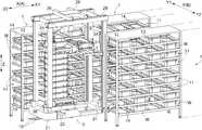
도 2는 반송차 및 용기 선반의 사시도
도 3는 반송차 및 용기 선반의 평면도
도 4는 리프팅 기구(lifting mechanism)의 사시도
도 5는 지지부를 지지 위치로 한 상태를 나타낸 리프팅 기구의 종단 정면도
도 6은 지지부를 퇴피 위치로 한 상태를 나타낸 리프팅 기구의 종단 정면도
도 7은 유지부(holding portion)가 인퇴(引退; withdrawn)하고 있는 상태를 나타낸 이송탑재 장치의 사시도
도 8은 유지부가 돌출되어 있는 상태를 나타낸 이송탑재 장치의 사시도
도 9는 반송차의 측면도
도 10은 물품 이송탑재 장치에 의해 물품을 이송탑재하고 있는 상태를 나타낸 반송차의 측면도
도 11은 재배열 장치(rearrangement apparatus)에 의해 용기의 재배열 순서를 변경할 때의 상태를 나타낸 반송차의 측면도
도 12는 재배열 장치에 의해 용기의 재배열 순서를 변경할 때의 상태를 나타낸 반송차의 측면도1 is a plan view of a conveying facility
2 is a perspective view of a transport vehicle and a container shelf
3 is a plan view of a transport vehicle and a container shelf
4 is a perspective view of a lifting mechanism
5 is a longitudinal front view of a lifting mechanism showing a state where the support portion is in a support position.
Figure 6 is a longitudinal front view of the lifting mechanism showing a state in which the support portion is in a retracted position
Fig. 7 is a perspective view of a transport-mounted device showing a state where the holding portion is withdrawn.
Figure 8 is a perspective view of the transfer mounting device showing a state in which the holding portion protrudes
9 is a side view of a transport vehicle
10 is a side view of a transport vehicle showing a state in which a product is transported by a product transporting device
11 is a side view of a transport vehicle showing a state when a rearrangement order of containers is changed by a rearrangement apparatus
12 is a side view of a transport vehicle showing a state when a rearrangement order of containers is changed by a rearrangement device.
1. 실시형태1. Embodiment
반송차를 복수 구비한 반송 설비의 실시형태에 대하여 도면을 참조하여 설명한다.An embodiment of the conveying equipment provided with a plurality of conveying vehicles will be described with reference to the drawings.
도 1에 나타낸 바와 같이, 반송 설비는, 용기(W)를 수용하는 복수의 용기 선반(1)과, 용기(W)를 반송하는 복수의 반송차(2)와, 용기(W)를 상하 방향 Z로 단적(段積; stacking)한 용기군(WG)을 반입(搬入) 및 반출(搬出)하는 반출입부(3)와, 복수의 반송차(2)를 제어하는 제어 장치(H)를 구비하고 있다.As shown in FIG. 1, the conveying equipment is a plurality of
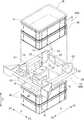
도 2 및 도 4에 나타낸 바와 같이, 용기(W)는, 바닥부의 주변에 측벽부를 세워 설치시켜 형성되어 있고, 상면이 개구된 상자형상으로 형성되어 있다. 본 예에서는, 용기(W)로서, 수지재에 의해 구성된 변형되지 않는 컨테이너를 사용하고 있다. 용기(W)의 측벽부에는, 용기(W)의 길이 방향을 따라 형성되어 있는 돌기부(6)[리브(rib)]나 용기(W)의 상하 방향 Z를 따라 형성되어 있는 돌기부(6)(리브)가 구비되어 있다. 그리고, 본 예에서는, 용기(W)는, 돌기부(6)에 용기 이송탑재 장치(24)의 유지부(46)가 걸어맞추어짐으로써, 용기 이송탑재 장치(24)에 의해 수평 방향으로 이동시키는 것이나 들어올리는 것이 가능하게 되어 있다. 그리고, 도 3에서의 용기 이송탑재 장치(24)에 의해 이송탑재(移載; transfer)되어 있는 용기(W)는, 상하 방향 Z를 따라 형성되어 있는 돌기부(6)를 나타내기 위해 횡단하여 일부를 절결(切缺)한 용기(W)를 도시하고 있다.2 and 4, the container W is formed by erecting and installing a side wall portion around the bottom portion, and is formed in a box shape with an open top surface. In this example, a non-deformable container made of a resin material is used as the container W. On the side wall portion of the container W, the projections 6 (ribs) formed along the longitudinal direction of the container W or the
도 2 및 도 4에 나타낸 바와 같이, 용기(W)의 상단부와 다른 용기(W)의 하단부가 상하 방향 Z로 끼워맞춤 가능하게 구성되어 있고, 용기(W)는, 상하 방향 Z로 단적 가능하게 구성되어 있다. 또한, 단적한 용기(W)는, 용기(W)의 바닥부와 상기 용기(W)의 위쪽에 단적한 다른 용기(W)의 바닥부와의 사이에 수용 공간이 형성되도록 되어 있고, 용기(W)에 물품을 수용한 상태로 용기(W)를 단적 가능하게 구성되어 있다.2 and 4, the upper end of the container W and the lower end of the other container W are configured to be fittable in the vertical direction Z, and the container W can be stacked in the vertical direction Z Consists of. In addition, the suitable container W is such that an accommodation space is formed between the bottom of the container W and the bottom of another container W suitable for the upper portion of the container W, and the container ( The container W is configured to be capable of being stacked in a state in which the article is accommodated in W).
[용기 선반][Container rack]
용기 선반(1)은, 용기(W)를 지지하는 선반부(11)를 상하 방향 Z로 복수 단 구비하고 있다. 선반부(11)에는, 단적하고 있지 않는 용기(W)가 용기 선반(1)의 선반 폭 방향(A)으로 배열되는 상태로 복수 지지된다.The
도 1에 나타낸 바와 같이, 복수의 용기 선반(1)은, 선반 폭 방향(A)을 따르는 자세로 설치되어 있다. 전면(前面)이 서로 대향하는 2개의 용기 선반(1)은, 선반 안길이 방향(B)에 간격을 둔 상태로 설치되어 있다. 이들 2개의 용기 선반(1)의 사이에는, 선반 간 통로(12)가 형성되어 있고, 선반 간 통로(12)는, 반송차(2)가 주행하는 통로로서 사용된다. 선반 폭 방향(A)을 따르는 자세의 복수의 용기 선반(1)이 선반 안길이 방향(B)에 배열되어 있고, 복수의 용기 선반(1)은, 선반 간 통로(12)가 복수 형성되도록 배치되어 있다. 반송차(2)가 선반 간 통로(12)를 주행할 때는, 반송차(2)는 용기 선반(1)의 전면을 따라 주행한다. 또한, 후면이 서로 대향하는 2개의 용기 선반(1)의 사이에는 선반 간 통로(12)는 형성되어 있지 않다.As shown in FIG. 1, the some
그리고, 용기 선반(1)의 길이 방향을 따른 방향을 선반 폭 방향(A), 상하 방향 Z에서 볼 때 선반 폭 방향(A)에 대하여 직교하는 방향을 선반 안길이 방향(B)이라고 하고 있다. 또한, 용기 선반(1)의 선반 간 통로(12)를 향하는 면을 전면, 용기 선반(1)의 선반 간 통로(12)를 향하는 면과는 반대측의 면을 후면이라고 하고 있다.And, the direction orthogonal to the shelf width direction (A) when viewed from the shelf width direction (A) and the vertical direction Z in the direction along the longitudinal direction of the container shelf (1) is referred to as the shelf depth direction (B). In addition, the surface facing the
도 2에 나타낸 바와 같이, 선반부(11)는, 제1 규제체(13)와 제2 규제체(14)를 구비하고 있다. 제1 규제체(13)는, 선반부(11)에 지지된 용기(W)에 대하여 선반 안길이 방향(B)의 양측에 위치하도록 구비되어 있고, 제2 규제체(14)는, 선반부(11)에 지지된 용기(W)에 대하여 선반 폭 방향(A)의 양측에 위치하도록 구비되어 있다. 선반부(11)에 지지된 용기(W)는, 제1 규제체(13)에 의해 선반 안길이 방향(B)으로 이동하는 것이 규제되고, 제2 규제체(14)에 의해 선반 폭 방향(A)으로 이동하는 것이 규제되고 있다.2, the
선반부(11)의 전방에는, 선반 폭 방향(A)을 따라 가이드 레일(15)이 설치되어 있다. 선반부(11)의 전방을 주행하는 반송차(2)는, 가이드 레일(15)에 의해 선반 안길이 방향(B)에 대한 이동이 규제된 상태로 선반 간 통로(12)를 선반 폭 방향(A)을 따라 주행한다.The
반출입부(3)는, 반입부(16)와 반출부(18)를 구비하고 있다. 반입부(16)에는, 물품을 수용하고 있지 않은 복수의 용기(W)가 상하 방향 Z로 단적된 용기군(WG)이 반입된다. 이 반입부(16)에 반입된 용기군(WG)을 구성하는 용기(W)는, 반송차(2)에 탑재하고, 반송차(2)에 의한 피킹 작업에 의해 물품이 수용된다. 반송차(2)에 탑재되어 있는 용기군(WG)을 구성하는 복수의 용기(W)에는 물품이 수용되고, 반송차(2)는, 물품을 수용한 용기군(WG)을 반출부(18)로 반송한다. 그리고, 반입부(16)로부터 반송차(2)에 탑재되는 복수의 용기(W)[용기군(WG)]은, 물품이 수용되어 있지 않은 빈 용기(W)이다. 반송차(2)로부터 반출부(18)로 반송되는 복수의 용기(W)[용기군(WG)]는, 물품을 수용한 실제의 용기(actual containers)(W)이다.The carrying-in
[반송차][Car]
도 2 및 도 3에 나타낸 바와 같이, 반송차(2)는, 바닥면 상을 주행하는 주행부(21)와, 용기(W)를 단적 상태로 지지하는 지지 영역(22)에 설치되어 지지 영역(22)의 용기(W)를 지지하는 컨베이어(23)와, 용기(W)를 이송탑재하는 용기 이송탑재 장치(24)와, 지지 영역(22)에 단적된 용기군(WG) 중 임의의 높이의 용기(W)를 그보다도 아래의 용기(W)에 대하여 들어올리는 리프팅 기구(25)를 구비하고 있다. 반송차(2)가 용기 선반(1)의 전면을 따라 주행하는 경우에 있어서, 용기 이송탑재 장치(24)는, 지지 영역(22)에 대하여 전후 방향 제1 측 X1에 인접하는 상태로 설치되어 있다. 용기 이송탑재 장치(24)는, 선반부(11)에 지지되어 있는 용기(W)의 지지 영역(22)에 대한 이송탑재와, 지지 영역(22)에 지지되어 있는 용기(W)의 선반부(11)에 대한 이송탑재를 행한다. 이하, 반송차(2)에 대하여 설명하지만, 반송차(2)가 선반 간 통로(12)에 위치하는 상태, 즉 반송차(2)가 용기 선반(1)의 전면을 따라 주행하고 있는 상태에 있어서, 선반 폭 방향(A)에 따른 방향을 전후 방향 X라고 하고, 전후 방향 X의 한쪽 측을 전후 방향 제1 측 X1, 그 반대측을 전후 방향 제2 측 X2라고 하고, 선반 안길이 방향(B)에 따른 방향이며 또한 상하 방향 Z에서 볼 때 전후 방향 X에 대하여 직교하는 방향을 좌우 방향 Y라고 하고, 좌우 방향 Y의 한쪽 측을 좌우 방향 제1 측 Y1, 그 반대측을 좌우 방향 제2 측 Y2라고 하여 설명한다.2 and 3, the
지지 영역(22)의 용기군(WG)은, 컨베이어(23)의 반송면(搬送面)에 지지되어 있다. 즉, 이 반송차(2)에서는, 컨베이어(23) 상에, 용기(W)를 단적 상태로 지지하는 지지 영역(22)이 형성되어 있다.The container group WG of the
컨베이어(23)는, 좌우 방향 Y를 따라 용기군(WG)을 반송하도록 설치되어 있다. 그러므로, 반송차(2)의 좌우 방향 Y로 반입부(16)가 인접하도록 반송차(2)를 정지시킨 상태에서, 컨베이어(23)를 작동시킴으로써, 반입부(16)의 용기군(WG)을 컨베이어(23) 상으로 반송할 수 있다. 또한, 반송차(2)의 좌우 방향 Y로 반출부(18)가 인접하도록 반송차(2)를 정지시킨 상태에서, 컨베이어(23)를 작동시킴으로써, 컨베이어(23) 상의 용기군(WG)을 반출부(18)로 반송할 수 있다.The
또한, 도 9에 나타낸 바와 같이, 반송차(2)는, 지지 영역(22)에 지지된 상태의 용기(W)인 제1 상태의 용기(W), 및 용기 이송탑재 장치(24)에 지지된 상태의 용기(W)인 제2 상태의 용기(W)의, 양쪽의 상태의 용기(W)에 수용되어 있는 물품을 인식하는 인식 장치(27)를 구비하고 있다.In addition, as shown in FIG. 9, the
인식 장치(27)는, 제1 상태의 용기(W)를 위쪽으로부터 촬상하여 제1 상태의 용기(W)에 수용되어 있는 물품을 인식하는 제1 촬상(撮像) 장치(27A)와, 제2 상태의 용기(W)를 위쪽으로부터 촬상하여 제2 상태의 용기(W)에 수용되어 있는 물품을 인식하는 제2 촬상 장치(27B)를 구비하고 있다.The
제1 촬상 장치(27A)는, 지지 영역(22)에 지지된 용기군(WG)보다도 위쪽에 설치되어 있고, 용기군(WG)의 최상단에 위치하는 용기(W)를 위쪽으로부터 촬상 가능하게 설치되어 있다.The
제2 촬상 장치(27B)는, 용기 이송탑재 장치(24)의 승강 이동 범위보다도 위쪽에 설치되어 있고, 용기 이송탑재 장치(24)(도 10 참조)를 설정 높이에 위치시킨 상태에서 상기 용기 이송탑재 장치(24)에 지지된 용기(W)를 촬상 가능하게 설치되어 있다.The
제1 촬상 장치(27A) 및 제2 촬상 장치(27B)는, 제1 마스트(mast)(37)의 상단부와 제2 마스트(52)의 상단부에 걸쳐 가설(架設)된 상부 프레임(28)에 지지되어 있다.The
[리프팅 기구][Lifting mechanism]
도 4에 나타낸 바와 같이, 리프팅 기구(25)는, 지지 영역(22)에 지지된 용기군(WG) 중 임의의 높이의 용기(W)를 그보다도 아래의 용기(W)에 대하여 들어올린다. 리프팅 기구(25)는, 용기(W)를 지지하는 지지부(31)와, 지지부(31)를 지지하여 상하 방향 Z를 따라 이동하는 승강부(32)와, 지지 영역(22)의 용기(W)를 적정 위치에 안내하는 안내부(33)를 구비하고 있다.As shown in FIG. 4, the
승강부(32)는, 상하 방향 Z에서 볼 때 직사각형으로 프레임 제작된 프레임체에 의해 구성되어 있고, 상하 방향 Z에서 볼 때 지지 영역(22)의 용기(W)의 주위를 에워싸도록 위치하고 있다. 승강부(32)는, 제1 모터(36)의 구동에 의해, 주행부(21)에 세워 설치된 제1 마스트(37)를 따라 상하 방향 Z로 이동한다.The lifting
도 4에 나타낸 바와 같이, 안내부(33)는, 승강부(32)에 지지되어 있고, 승강부(32)를 상하 방향 Z를 따라 이동시킨 경우에, 지지 영역(22)의 용기(W)에 접촉하여 상기 용기(W)를 지지 영역(22)의 적정 위치에 안내한다. 설명을 추가하면, 안내부(33)는, 제1 안내부(41)와 제2 안내부(42)를 구비하고 있다. 제1 안내부(41)는, 안내부(33)에서의 승강부(32)로부터 위쪽으로 돌출하는 부분에 구비되어 있다. 제2 안내부(42)는, 안내부(33)에서의 승강부(32)로부터 아래쪽으로 돌출하는 부분에 구비되어 있다. 제1 안내부(41)는, 상하 방향 Z에서 볼 때 적정 위치의 용기(W)에 대하여 전후 방향 제2 측 X2 및 좌우 방향 Y의 양측에 위치하도록 구비되어 있다. 제2 안내부(42)는, 상하 방향 Z에서 볼 때 적정 위치의 용기(W)에 대하여 전후 방향 X의 양측 및 좌우 방향 Y의 양측에 위치하도록 구비되어 있다.4, the
제1 안내부(41)는, 상방 측을 향함에 따라 적정 위치의 용기(W)로부터 이격되는 경사면을 구비하고 있다. 승강부(32)가 상방 측으로 이동할 때, 지지 영역(22)의 용기군(WG)에 적정 위치로부터 수평 방향으로 어긋난 용기(W)가 존재하는 경우에는, 그 용기(W)에 제1 안내부(41)의 경사면이 접촉하여 용기(W)를 적정 위치 측으로 안내함으로써, 적정 위치로부터 어긋나 있는 용기(W)를 적정 위치로 이동시키는 것이 가능하다.The
또한, 제2 안내부(42)는, 하방측을 향함에 따라 적정 위치의 용기(W)로부터 이격되는 경사면을 구비하고 있다. 승강부(32)가 하방측으로 이동할 때, 지지 영역(22)의 용기군(WG)에 적정 위치로부터 수평 방향으로 어긋난 용기(W)가 존재하는 경우에는, 이 용기(W)에 제2 안내부(42)의 경사면이 접촉하여 용기(W)를 적정 위치 측으로 안내함으로써, 적정 위치로부터 어긋나 있는 용기(W)를 적정 위치로 이동시키는 것이 가능하다.Moreover, the
그리고, 용기(W)의 적정 위치는, 지지 영역(22)에 대하여 미리 설정된 용기(W)의 위치이며, 단적된 복수의 용기(W)의 적정 위치는, 상하 방향 Z에서 볼 때 같은 위치로 되어 있다.Then, the proper position of the container W is the position of the container W preset with respect to the
리프팅 기구(25)는, 제3 안내부(43)를 구비하고 있다. 이 제3 안내부(43)는, 승강부(32)보다도 위쪽에 위치하도록 승강부(32)에 지지되어 있다. 제3 안내부(43)는, 전후 방향 제1 측 X1을 향함에 따라 좌우 방향 Y로 있어서 적정 위치의 용기(W)로부터 이격되는 경사면을 구비하고 있다. 도 10에 나타낸 바와 같이, 용기 이송탑재 장치(24)에 의해 지지 영역(22)의 용기군(WG)에 용기(W)를 탑재하는 경우에 있어서, 상기 용기(W)가 적정 위치로부터 좌우 방향 Y로 어긋나 있는 경우에는, 이 용기(W)에 제3 안내부(43)의 경사면이 접촉하여 좌우 방향 Y로 있어서 용기(W)를 적정 위치로 이동시킨다.The
도 4 내지 도 6에 나타낸 바와 같이, 지지부(31)는, 상하 방향 Z에서 볼 때 지지 영역(22)의 용기(W)의 돌기부(6)와 중첩되는 지지 위치(도 4 및 도 5 참조)와, 상하 방향 Z에서 볼 때 지지 영역(22)의 용기(W)와 중첩되지 않는 퇴피 위치(도 6 참조)로 이동 가능하게 구성되어 있다. 설명을 추가하면, 지지부(31)는 중앙이 팽출(膨出)하는 판형으로 형성되어 있고, 제2 모터(44)의 구동에 의해 전후 방향 X를 따르는 축심(軸心) 주위로 회전함으로써, 전후 방향 X 및 좌우 방향 Y를 따르는 회전 위치로 되는 지지 위치와, 전후 방향 X 및 상하 방향 Z를 따르는 회전 위치로 되는 퇴피 위치로 이동한다.4 to 6, the
도 6에 나타낸 바와 같이, 리프팅 기구(25)는, 지지부(31)를 퇴피 위치로 함으로써, 승강부(32)를 상하 방향 Z로 이동시킬 때 지지부(31)가 지지 영역(22)의 용기군(WG)에 접촉하는 것을 회피할 수 있다.As shown in Fig. 6, the
그리고, 도 5에 나타낸 바와 같이, 리프팅 기구(25)는, 지지 영역(22)의 용기군(WG) 중 임의의 용기(W)에 대응하는 높이로 승강부(32)를 이동시킨 상태에서, 지지부(31)를 퇴피 위치로부터 지지 위치로 이동시키고, 그 후, 승강부(32)를 상승시킨다. 이로써, 임의의 용기(W)의 돌기부(6)에 지지부(31)가 걸어맞추어지고, 임의의 용기(W)를 들어올리는 것이 가능하다. 이 때, 임의의 용기(W)보다도 위에 다른 용기(W)가 단적되어 있는 경우에는, 임의의 용기(W)와 함께 이보다도 위에 단적되어 있는 용기(W)를 들어올리는 것이 가능하다. 이와 같이, 리프팅 기구(25)는, 지지 영역(22)에 단적되어 있는 용기군(WG) 중 임의의 용기(W) 및 이 임의의 용기(W)보다도 위의 용기(W)를 모아 들어올리는 것이 가능하다.And, as shown in FIG. 5, the
리프팅 기구(25)는, 용기(W)를 들어올린 상태로부터 승강부(32)를 하강시킴으로써, 지지부(31)에 의해 지지하고 있었던 1개 또는 복수의 용기(W)를, 컨베이어(23) 상, 또는 컨베이어(23)의 지지 영역(22)에 용기(W)가 존재하는 경우에는 그 용기(W) 상에 단적할 수 있다.The
[용기 이송탑재 장치][Container transfer device]
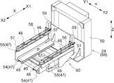
도 7 및 도 8에 나타낸 바와 같이, 용기 이송탑재 장치(24)는, 용기(W)의 외면을 유지하여 용기(W)를 이동시키도록 구성되어 있다. 용기 이송탑재 장치(24)는, 용기(W)를 유지하는 유지부(46)와, 유지부(46)를 지지하고 또한 수평 방향을 따라 출퇴(出退; projecting and retracting) 가능한 출퇴부(47)와, 용기(W)의 바닥면을 아래쪽으로부터 지지하는 지지체(48)와, 출퇴부(47) 및 지지체(48)를 지지하고 또한 상하 방향 Z를 따르는 세로 축심 주위로 회전 가능한 회전부(49)와, 회전부(49)를 지지하는 베이스부(50)를 구비하고 있다. 유지부(46) 및 출퇴부(47)는, 출퇴부(47)의 출퇴 방향에 대하여 상하 방향 Z에서 볼 때 직교하는 방향으로 배열되는 상태로 한 쌍 구비되어 있다. 유지부(46), 출퇴부(47), 및 회전부(49)에 의해, 용기(W)를 이송탑재하는 이송탑재부(60)가 구성되어 있고, 이송탑재부(60)는, 선반부(11)와 지지체(48)와의 사이에서 용기(W)를 이송탑재하고 또한 지지체(48)와 지지 영역(22)과의 사이에서 용기(W)를 이송탑재한다.As shown in FIG. 7 and FIG. 8, the
도 9 및 그 이후의 도면에 나타낸 바와 같이, 용기 이송탑재 장치(24)는, 지지체(48)에 지지된 용기(W)의 높이가, 컨베이어(23)에 지지된 용기군(WG)의 최하단의 용기(W)보다도 낮아지는 높이로부터, 컨베이어(23)에 규정 수(본 실시형태에서는 10)의 용기(W)를 단적한 용기군(WG)의 최상단의 용기(W)보다도 높아지는 높이까지, 승강 가능하게 구성되어 있다. 또한, 용기 이송탑재 장치(24)는, 용기 선반(1)에 구비된 선반부(11)의 각각에 대응하는 높이(이송탑재용 높이)로 승강 가능하다. 최하단의 선반부(11)에 대응하는 이송탑재용 높이는, 컨베이어(23)에 지지된 용기군(WG)의 최하단의 용기(W)보다도 낮은 높이로, 용기(W)를 지지체(48)에 의해 지지하는 높이로 설정되어 있다.As shown in FIG. 9 and subsequent drawings, the height of the container W supported by the
베이스부(50)는, 제3 모터(51)의 구동에 의해, 주행부(21)에 세워 설치된 제2 마스트(52)를 따라 상하 방향 Z로 이동한다. 베이스부(50)는, 회전부(49) 및 출퇴부(47)가 개재(介在)하는 상태로 유지부(46)를 지지하고 있고, 제3 모터(51)에 의해 베이스부(50)가 상하 방향 Z를 따라 이동함으로써, 유지부(46)가 상하 방향 Z를 따라 이동한다. 그리고, 제3 모터(51)가, 유지부(46)를 상하 방향 Z를 따라 이동시키는 상하 구동부에 상당한다.The
회전부(49)는, 내장된 모터의 구동에 의해, 상하 방향 Z를 따르는 세로 축심(P) 주위로 회전한다. 회전부(49)는, 출퇴부(47)를 지지하고 있고, 회전부(49)가 세로 축심(P) 주위로 회전함으로써, 출퇴부(47)가 세로 축심 주위로 회전하여, 출퇴부(47)에 의해 유지부(46)가 돌출하는 방향을 세로 축심(P) 주위로 변경한다. 구체적으로는, 회전부(49)가 세로 축심(P) 주위로 회전함으로써, 출퇴부(47)에 의해 유지부(46)가 돌출하는 방향을, 적어도 좌우 방향 제1 측 Y1와, 좌우 방향 제2 측 Y2와, 전후 방향 제2 측 X2로 변경할 수 있다. 그리고, 회전부(49)가, 출퇴부(47)를 세로 축심(P) 주위로 회전시켜 출퇴부(47)에 의해 유지부(46)가 돌출하는 방향을 변경시키는 회전 구동부에 상당한다. 이하, 유지부(46)가 돌출하는 방향을 좌우 방향 제1 측 Y1으로 한 용기 이송탑재 장치(24) 상태를, 제1 선반 이송탑재 상태라고 하고, 유지부(46)가 돌출하는 방향을 좌우 방향 제2 측 Y2로 한 용기 이송탑재 장치(24) 상태를, 제2 선반 이송탑재 상태라고 하고, 유지부(46)가 돌출하는 방향을 전후 방향 제2 측 X2로 한 용기 이송탑재 장치(24) 상태를, 단적 이송탑재 상태라고 한다.The
한 쌍의 출퇴부(47)의 각각은, 회전부(49)에 지지된 고정부(54)와, 고정부(54)에 대하여 수평 방향으로 출퇴 이동하는 이동부(55)와, 이동부(55)를 고정부(54)에 대하여 수평 방향으로 출퇴 이동시키는 제4 모터(56)를 구비하고 있다. 이동부(55)는, 상하 방향 Z를 따르는 축심 주위로 회전 가능한 한 쌍의 풀리(pully)(57)에 권취된 벨트(58)와, 한 쌍의 풀리(57중 (한쪽을 회전 구동시키는 제5 모터(59)를 구비하고 있다. 벨트(58)에는 유지부(46)가 고정되어 있다.Each of the pair of
출퇴부(47)는, 제4 모터(56)에 의한 이동부(55)의 출퇴 이동과 제5 모터(59)에 의한 벨트(58)의 회동(回動)에 의해, 유지부(46)를 수평 방향을 따라 이동시키고, 유지부(46)를 인퇴(retract) 위치(도 7 참조) 곳의 인퇴 위치로부터 수평 방향으로 돌출된 돌출 위치(도 8 참조)로 이동시킨다. 그리고, 이 출퇴부(47)이, 유지부(46)를 수평 방향을 따라 이동시키는 수평 구동부에 상당한다.The
또한, 벨트(58)의 양 단부(端部)(도 3에 나타낸 자세에서는 좌우 방향 Y의 양 단부, 도 7 및 도 8에 나타낸 자세에서는 전후 방향 X의 양 단부)에서는, 유지부(46)가 풀리(57)의 외주면(外周面)을 따라 이동함으로써, 한쪽의 출퇴부(47)에 지지되어 있는 유지부(46)와, 다른 쪽의 출퇴부(47)에 지지되어 있는 유지부(46)와의 간격을 변경할 수 있다. 이들 한 쌍의 유지부(46)의 간격은, 한 쌍의 유지부(46)가 용기(W)에 걸어맞추어지는 걸어맞춤 간격과, 한 쌍의 유지부(46)가 용기(W)로부터 이탈하는 이탈 간격으로 변경할 수 있다. 그리고, 한 쌍의 유지부(46)에 의해 용기(W)를 유지한다는 것은, 유지부(46)가 출퇴 이동한 경우에 용기(W)의 돌기부(6)에 걸어맞추어져 용기(W)를 이동시킬 수 있는 것을 나타내고 있고, 한 쌍의 유지부(46)에 의해 용기(W)를 협지하고 있지 않아도 된다.Further, at both ends of the belt 58 (both ends in the left and right directions Y in the posture shown in FIG. 3, and both ends in the front-rear direction X in the posture shown in FIGS. 7 and 8), the holding
용기 이송탑재 장치(24)에 의해, 지지 영역(22)에 지지되어 있는 용기(W)를 지지체(48)로 이송탑재하는 경우에 대하여, 도 11을 참조하여 설명한다.The case where the container W supported by the
용기 이송탑재 장치(24)는, 먼저, 회전부(49)를 세로 축심(P) 주위로 회전시켜, 용기 이송탑재 장치(24)를 단적 이송탑재 상태로 하고 또한 베이스부(50)를 승강시켜, 지지 영역(22)에서의 이송탑재 대상의 용기(W)에 대응하는 이송탑재용 높이로 용기 이송탑재 장치(24)를 승강시킨다. 그리고, 용기 이송탑재 장치(24)를 인퇴 상태[유지부(46)가 인퇴 위치에 위치하는 상태]로부터 돌출 상태(유지부(46)가 돌출 위치에 위치하는 상태)로 전환한 후, 한 쌍의 유지부(46)의 간격을 이탈 간격으로부터 걸어맞춤 간격으로 변경하여, 한 쌍의 유지부(46)에 의해 용기(W)를 유지한다. 이 후, 유지부(46)를 인퇴 위치로 이동시켜, 지지 영역(22)의 용기(W)를 지지체(48)로 이송탑재한다. 그리고, 이송탑재 대상의 용기(W)가 다른 용기(W) 상에 단적되어 있는 경우에는, 한 쌍의 유지부(46)에 의해 용기(W)를 유지한 후, 베이스부(50)를 상승시켜 이송탑재 대상의 용기(W) 중 적어도 전단부(前端部)와 아래쪽에 인접하는 용기(W)와의 끼워맞춤을 분리한 후, 유지부(46)를 인퇴 위치로 이동시킨다. 또한, 이송탑재 대상의 용기(W) 상에 다른 용기(W)가 단적되어 있는 경우에는, 리프팅 기구(25)에 의해 이송탑재 대상의 용기(W)보다도 위쪽의 다른 용기(W)를 들어올린 상태로, 용기 이송탑재 장치(24)에 의한 이송탑재를 행한다.The
다음에, 용기 이송탑재 장치(24)에 의해, 지지체(48)에 지지되어 있는 용기(W)를 지지 영역(22)으로 이송탑재하는 경우에 대하여, 도 12를 참조하여 설명한다. 설명한다.Next, a case where the container W supported by the
용기 이송탑재 장치(24)는, 먼저, 회전부(49)를 세로 축심(P) 주위로 회전시켜, 용기 이송탑재 장치(24)를 단적 이송탑재 상태로 하고 또한 베이스부(50)를 승강시켜, 지지 영역(22)에서의 이송탑재용 높이에 용기 이송탑재 장치(24)를 승강시킨다. 그리고, 걸어맞춤 간격의 한 쌍의 유지부(46)에 의해 용기(W)를 유지한 상태로, 용기 이송탑재 장치(24)를 인퇴 상태로부터 돌출 상태로 전환하여, 지지체(48)에 지지되어 있는 용기(W)를 지지 영역(22)의 용기(W)에 단적한다. 그 후, 한 쌍의 유지부(46)의 간격을 걸어맞춤 간격으로부터 이탈 간격으로 변경하여 이송탑재 대상의 용기(W)에 대한 유지를 해제한 후, 유지부(46)를 인퇴 위치로 이동시킨다. 그리고, 지지 영역(22)에 용기(W)가 존재하지 않을 경우에는 이송탑재 대상의 용기(W)는 컨베이어(23) 상에 이송탑재한다. 또한, 단적되어 있는 용기군(WG)의 중간의 이송탑재 대상 위치에 용기(W)를 이송탑재하는 경우에는, 리프팅 기구(25)에 의해 이송탑재 대상 위치보다도 위쪽의 용기(W)를 들어올린 상태로, 용기 이송탑재 장치(24)에 의한 이송탑재를 행한다.The
용기 이송탑재 장치(24)에 의해, 선반부(11)에 지지되어 있는 용기(W)를 지지체(48)로 이송탑재하는 경우나, 용기 이송탑재 장치(24)에 의해, 지지체(48)에 지지되어 있는 용기(W)를 선반부(11)로 이송탑재하는 경우에 대해서는, 용기 이송탑재 장치(24) 상태를 단적 이송탑재 상태 대신에 제1 선반 이송탑재 상태 또는 제2 선반 이송탑재 상태로 하는 것이나, 이송탑재 대상의 용기(W)가 단적되어 있지 않은 경우라도 제1 규제체(13)를 타고넘기 위해 베이스부(50)를 상승시키는 것 이외에는, 지지체(48)에 지지되어 있는 용기(W)를 지지 영역(22)으로 이송탑재하는 경우와 마찬가지로 용기 이송탑재 장치(24)를 동작시키므로, 설명은 생략한다.When the container W supported by the
[물품 이송탑재 장치][Goods transfer device]
반송차(2)는, 물품을 이송탑재하는 물품 이송탑재 장치(26)를 구비하고 있다. 물품 이송탑재 장치(26)는, 용기(W)의 개구부로부터 용기(W)에 수용되어 있는 물품을 유지하여 인출하도록 구성되어 있고, 인식 장치(27)에 의해 인식된 물품을 제1 상태의 용기(W)와 제2 상태의 용기(W)와의 사이에서 이송탑재한다. 물품 이송탑재 장치(26)는, 제1 촬상 장치(27A)에 촬상된 물품을 제1 상태의 용기(W)로부터 제2 상태의 용기(W)로 이송탑재한다. 또한, 물품 이송탑재 장치(26)는, 제2 촬상 장치(27B)에 촬상된 물품을 제2 상태의 용기(W)로부터 제1 상태의 용기(W)로 이송탑재한다. 물품 이송탑재 장치(26)는, 상부 프레임(28)에 지지된 지지 프레임(29)에 지지되어 있다.The
도 9에 나타낸 바와 같이, 물품 이송탑재 장치(26)는, 시트부(seat portion)(61)와 선회부(旋回部)(62)와 제1 암(arm)(63)과 제2 암(64)과 제3 암(65)과 물품 유지부(66)를 구비하고 있다. 시트부(61)는, 상부 프레임(28)에 고정되어 있다. 선회부(62)는, 시트부(61)에 대하여 상하 방향 Z를 따르는 축심 주위로 회전 가능하게 지지되어 있다. 제1 암(63)의 기단부(基端部)가, 선회부(62)에 요동(搖動) 가능하게 연결되어 있다. 제1 암(63)은, 선회부(62)에 대하여 수평 방향을 따르는 축심 주위로 요동 가능하게 되어 있다. 제2 암(64)의 기단부가, 제1 암(63)의 선단부에 요동 가능하게 연결되어 있다. 제2 암(64)은, 제1 암(63)에 대하여 수평 방향을 따르는 축심 주위로 요동 가능하게 되어 있다. 제2 암(64)은, 제2 암(64)의 길이 방향의 중간부에 있어서 제2 암(64)의 길이 방향을 따른 축심 주위로 회전 가능하게 구성되어 있다. 제3 암(65)의 기단부가, 제2 암(64)의 선단부에 요동 가능하게 연결되어 있다. 또한, 제3 암(65)의 선단부에, 제3 암(65)의 길이 방향을 따라 회전 가능하게 물품 유지부(66)가 연결되어 있다. 이와 같이, 물품 이송탑재 장치(26)는, 수직 다관절 로봇(6축 로봇)에 의해 구성되어 있다.As shown in Fig. 9, the
물품 유지부(66)는, 물품을 흡착에 의해 유지하는 흡착 패드를 구비하고 있고, 물품을 흡착지지한다.The
[재배열 장치][Rearrangement device]
도 11 및 도 12에 나타낸 바와 같이, 반송차(2)는, 지지 영역(22)에 지지된 용기군(WG)의 용기(W)의 재배열 순서를 바꾸는 재배열 장치(68)를 구비하고 있다. 재배열 장치(68)은, 리프팅 기구(25)와 용기 이송탑재 장치(24)를 구비하고 있다.11 and 12, the
재배열 장치(68)는, 다음과 같이 하여 용기군(WG)의 용기(W)의 재배열 순서를 바꾼다.The
즉, 먼저, 리프팅 기구(25)에 의해 용기군(WG)의 임의의 용기(W)를 그보다도 아래의 용기(W)에 대하여 들어올린다. 다음에, 용기군(WG) 중의 리프팅 기구(25)에 의해 들어올리지 않았던 용기(W) 중의 최상단에 위치하는 용기(W)를, 용기 이송탑재 장치(24)에 의해 지지 영역(22)으로부터 지지체(48) 상에 이송탑재한다.That is, first, the arbitrary container W of the container group WG is lifted with respect to the container W below it by the
그 후, 리프팅 기구(25)에 의해, 들어올려 있었던 용기(W)를 들어올리지 않았던 용기(W)에 단적하여, 그 단적한 용기군(WG)[용기 이송탑재 장치(24)에 의해 이송탑재한 용기(W)는 제외]에 대하여, 용기 이송탑재 장치(24)가, 지지체(48) 상의 용기(W)를 단적한다.Thereafter, by the
이와 같이, 리프팅 기구(25)에 의해 들어올리는 임의의 용기(W)의 일단(一段) 아래의 용기(W)를, 용기군(WG)의 최상단으로 이동시키도록 하고, 용기군(WG)의 용기(W)의 재배열 순서를 바꾼다. 본 실시형태에서는, 임의의 용기(W)를 용기군(WG)에서의 아래로부터 2단째의 용기(W)로 하고 있다.Thus, the container W below one end of the arbitrary container W lifted by the
또한, 리프팅 기구(25)는, 제1 상태의 용기(W)가 제1 촬상 장치(27A)에 대하여 아래쪽에 크게 이격되어 있으므로, 제1 촬상 장치(27A)에 의해 제1 상태의 용기(W)에 수용되어 있는 물품을 인식할 수 없는 경우에는, 제1 상태의 용기(W)를 제1 설정 높이까지 들어올려도 된다. 구체적으로는, 지지 영역(22)에 지지되어 있는 용기군(WG)의 수가 적은 경우[예를 들면, 용기군(WG)을 구성하는 용기(W)의 수가 5개의 경우]에서는, 제1 상태의 용기(W)의 높이가 낮고, 제1 상태의 용기(W)가 제1 촬상 장치(27A)에 대하여 아래쪽으로 크게 떨어지므로, 제1 촬상 장치(27A)에 의해 제1 상태의 용기(W)에 수용되어 있는 물품을 인식하기 어렵다. 이와 같은 경우에는, 리프팅 기구(25)에 의해, 제1 상태의 용기(W)를 제1 설정 높이까지 들어올린 상태에서, 제1 촬상 장치(27A)에 의해 제1 상태의 용기(W)에 수용되어 있는 물품을 인식한다. 그리고, 본 실시형태에서는, 제1 설정 높이는, 10개의 용기(W)로 구성한 용기군(WG)을 컨베이어(23) 상에 탑재한 상태에서의 최상단에 위치하는 용기(W)의 높이로 하고 있다.In addition, the
또한, 리프팅 기구(25)는, 제1 상태의 용기(W)가 물품 이송탑재 장치(26)에 대하여 아래쪽으로 크게 이격되어 있으므로, 물품 이송탑재 장치(26)에 의해 제1 상태의 용기(W)에 적절히 물품을 이송탑재할 수 없는 경우에는, 제1 상태의 용기(W)를 제2 설정 높이까지 들어올려도 된다. 구체적으로는, 지지 영역(22)에 지지되어 있는 용기군(WG)의 수가 적은 경우[예를 들면, 용기군(WG)을 구성하는 용기(W)의 수가 5개의 경우]에서는, 제1 상태의 용기(W)의 높이가 낮고, 제1 상태의 용기(W)가 물품 이송탑재 장치(26)에 대하여 아래쪽으로 크게 떨어지므로, 물품 이송탑재 장치(26)에 의해 제1 상태의 용기(W)에 물품을 적절히 이송탑재하기 어렵다. 이와 같은 경우에는, 리프팅 기구(25)에 의해, 제1 상태의 용기(W)를 제2 설정 높이까지 들어올린 상태에서, 물품 이송탑재 장치(26)에 의해 제1 상태의 용기(W)로 물품을 이송탑재한다. 그리고, 본 실시형태에서는, 제2 설정 높이는, 10개의 용기(W)로 구성한 용기군(WG)을 컨베이어(23) 상에 탑재한 상태에서의 최상단에 위치하는 용기(W)의 높이로 하고 있고, 제1 설정 높이와 같은 높이로 하고 있다.In addition, the
[제어 장치][controller]
도 1에 나타낸 바와 같이, 제어 장치(H)는, 복수의 반송차(2)의 주행 경로(travelling route)(R)를 설정하고 또한 복수의 반송차(2)가 주행 경로(R)를 따라 주행하도록 반송차(2)를 제어한다. 주행 경로(R)는, 선반 폭 방향(A)을 따르는 경로나 선반 안길이 방향(B)을 따르는 경로를 가지고 있고, 제어 장치(H)는, 주행 경로(R)를 일방향으로 주행하도록 반송차(2)를 제어한다. 그러므로, 2개의 용기 선반(1)의 사이에 형성되는 선반 간 통로(12)에 있어서는, 반송차(2)의 주행 방향은 일방향으로 된다. 그리고, 예를 들면, 복수의 반출입부(3) 중 하나인 대상 반출입부(3A)에서 용기군(WG)을 반송차(2)에 탑재하고, 복수의 용기 선반(1)의 일부인 복수의 대상 용기 선반(1A)에 수납되어 있는 용기(W)로부터 물품을 인출한 후, 대상 반출입부(3A)에 용기군(WG)을 내려놓는 경우에는, 제어 장치(H)는, 도 1에 있어서 굵은 실선으로 나타낸 주행 경로(R)를 따라 반송차(2)가 주행하여 복수의 대상 용기 선반(1A)에 수납되어 있는 용기(W)로부터 물품을 인출하기 위한 반송 지령을 반송차(2)에 송신하여, 반송차(2)를 제어한다.As shown in Fig. 1, the control device H sets the traveling route R of the plurality of
그리고, 도 1에 있어서는, 반송차(2)의 주행 경로(R)를 1점 쇄선 및 굵은 실선으로 나타내고 있다. 또한, 도 1에 있어서는, 반송차(2)의 주행 방향을 화살표로 나타내고 있다.In addition, in FIG. 1, the travel path R of the
반송차(2)에 구비된 제어부(69)는, 제어 장치(H)로부터의 반송 정보에 기초하여, 다음과 같이 하여 반송차(2)를 제어한다.The
제어부(69)는, 용기군(WG)을 반송차(2)에 탑재하는 반입 제어와, 제2 상태의 용기(W)와 제1 상태의 용기(W)와의 사이에서 물품을 이송탑재하는 이송탑재 제어와, 용기군(WG)을 반송차(2)로부터 내려놓는 반출 제어(transfer control)와, 지지 영역(22)과 선반부(11)와의 사이에서 용기(W)를 바꿔 넣는 교환 제어(exchange control)를 실행한다. 본 실시형태에서는, 이송탑재 제어에서는, 물품의 제1 상태의 용기(W)로부터 제2 상태의 용기(W)에 대한 이송탑재와, 물품의 제2 상태의 용기(W)로부터 제1 상태의 용기(W)에 대한 이송탑재 중, 물품의 제2 상태의 용기(W)로부터 제1 상태의 용기(W)에 대한 이송탑재만을 행한다. 제어부(69)는, 반입 제어를 실행하여 반입부(16)의 용기군(WG)을 반송차(2)의 컨베이어(23)에 탑재한 후, 이송탑재 제어를 복수 회 실행하여 용기군(WG)을 구성하는 복수의 용기(W)의 각각에 물품을 수용하고, 그 후, 반출 제어를 실행하여 컨베이어(23) 상의 용기군(WG)을 반출부(18)에 내려놓는다.The
반입 제어에서는, 반입부(16)에 반송차(2)가 인접하여 정지하도록 주행부(21)를 제어한 후, 용기군(WG)을 반입부(16)로부터 지지 영역(22)에 이송탑재하도록 컨베이어(23)를 제어한다.In the carrying-in control, after the traveling
반출 제어에서는, 반출부(18)에 반송차(2)가 인접하여 정지하도록 주행부(21)를 제어한 후, 용기군(WG)을 지지 영역(22)으로부터 반출부(18)에 이송탑재하도록 컨베이어(23)를 제어한다.In the carrying-out control, after the traveling
다음에, 이송탑재 제어에 대하여 설명한다.Next, the transfer-mounting control will be described.
이송탑재 제어에서는, 대상 용기 선반(1A)에 수용되어 있는 용기(W)를 용기 이송탑재 장치(24)에 의해 지지체(48) 상에 인출하는 인출 처리와, 물품 이송탑재 장치(26)에 의해 제2 상태의 용기(W)로부터 제1 상태의 용기(W)로 물품을 이송탑재하는 이송탑재 처리와, 지지체(48) 상의 용기(W)를 대상 용기 선반(1A)에 수납하는 수납 처리와, 용기군(WG)의 용기(W)의 재배열 순서를 바꾸는 교환 처리를 실행한다. 이송탑재 제어에서는, 인출 처리, 이송탑재 처리, 수납 처리의 순으로 실행하고 또한 필요에 따라 교환 처리를 실행한다. 그리고, 통상은 수납 처리 후에 교환 처리를 실행하지만, 이송탑재 제어에 의해 물품을 수용한 용기(W)가 최후의 용기(W)의 경우[이송탑재 제어에 의해 용기군(WG)을 구성하는 용기(W)의 모두에 물품이 수용된 경우] 등에서는, 이송탑재 제어에 있어서 교환 처리를 행하지 않을 경우가 있다.In the transport loading control, the container W accommodated in the
인출 처리에서는, 대상 용기 선반(1A)에서의 인출 대상의 용기(W)를 지지하는 선반부(11)에 대응하는 이송탑재용 높이에 용기 이송탑재 장치(24)를 승강시킨 후, 인출 대상의 용기(W)를 선반부(11)로부터 지지체(48)에 이송탑재하도록, 용기 이송탑재 장치(24)를 제어한다. 이와 같이, 인출 처리를 실행함으로써, 대상 용기 선반(1A)에 수용되어 있었던 인출 대상의 용기(W)는, 지지체(48)에 지지되고, 제2 상태의 용기(W)가 된다.In the withdrawal processing, after the container
수납 처리는, 지지체(48)가 지지하고 있는 용기(W)가 수납되어 있었던 선반부(11)에 대응하는 이송탑재용 높이에 용기 이송탑재 장치(24)를 승강시킨 후, 지지체(48)로부터 선반부(11)에 이송탑재하도록, 용기 이송탑재 장치(24)를 제어한다.The storage processing is carried out by lifting the
이송탑재 처리에서는, 제2 촬상 장치(27B)의 촬상 정보에 기초하여 제2 상태의 용기(W)에 수용되어 있는 물품의 위치나 종류 등을 인식하고, 용기 선반(1)으로부터 인출하는 대상인 인출 대상의 물품을 제2 상태의 용기(W)로부터 제1 상태의 용기(W)에 이송탑재하도록, 물품 이송탑재 장치(26)를 제어한다. 그 후, 이송탑재 처리에서는, 제1 촬상 장치(27A)에 의해, 제1 상태의 용기(W)에 수용되어 있는 물품의 위치나 종류 등을 인식하고, 물품 이송탑재 장치(26)에 의해 물품의 이송탑재가 적절히 행해지고 있는지 확인한다.In the transfer-mounting process, the position, type, and the like of the article stored in the container W in the second state are recognized based on the imaging information of the
또한, 이송탑재 처리에서는, 제1 촬상 장치(27A)의 촬상 정보에 기초하여 제1 상태의 용기(W)에 수용되어 있는 물품의 위치나 종류 등을 인식하고, 용기 선반(1)에 수납하는 대상인 인출 대상의 물품을 제1 상태의 용기(W)로부터 제2 상태의 용기(W)에 이송탑재하도록, 물품 이송탑재 장치(26)를 제어한다. 그 후, 이송탑재 처리에서는, 제2 촬상 장치(27B)에 의해, 제2 상태의 용기(W)에 수용되어 있는 물품의 위치나 종류 등을 인식하고, 물품 이송탑재 장치(26)에 의해 물품의 이송탑재가 적절히 행해지고 있는지 확인한다. 그리고, 지지 영역(22)에 지지되어 있는 용기군(WG)에서의 최상단의 용기(W)가 제1 상태의 용기(W)로 되어 있다.In addition, in the transfer-mounting process, based on the imaging information of the
교환 처리에서는, 먼저, 리프팅 기구(25)에 의해, 용기군(WG) 중 임의의 높이의 용기(W)를 들어올리고, 용기 이송탑재 장치(24)에 의해, 용기군(WG)에서의 임의의 높이의 용기(W)의 일단 아래의 용기(W)를 지지 영역(22)으로부터 지지체(48) 상에 이송탑재하도록, 리프팅 기구(25) 및 용기 이송탑재 장치(24)를 제어한다. 교환 처리에서는, 다음에, 리프팅 기구(25)에 의해 들어올려 있었던 임의의 높이의 용기(W)를 끌어 내려, 용기 이송탑재 장치(24)에 의해 용기(W)[임의의 높이의 용기(W)의 일단 아래에 위치하고 있었던 용기(W)]를 용기군(WG)에서의 최상단의 용기(W) 상에 탑재하도록, 리프팅 기구(25) 및 용기 이송탑재 장치(24)를 제어한다. 이와 같이, 교환 처리를 실행함으로써, 임의의 높이의 용기(W)의 일단 아래에 위치하고 있었던 용기(W)는, 용기군(WG)에 탑재되어 최상단의 용기(W)로 되고 또한 제1 상태의 용기(W)로 된다.In the exchange process, first, the container W of a certain height among the container groups WG is lifted by the
본 실시형태에서는, 용기군(WG) 중 임의의 높이의 용기(W)를, 용기군(WG)에서의 아래로부터 2단째의 용기(W)로 하고 있다. 따라서, 교환 처리에서는, 먼저, 리프팅 기구(25)에 의해, 용기군(WG)에서의 아래로부터 2단째의 용기(W)를 들어올리고, 용기 이송탑재 장치(24)에 의해, 용기군(WG)에서의 최하단의 용기(W)를 지지 영역(22)으로부터 지지체(48) 상에 이송탑재하도록, 리프팅 기구(25) 및 용기 이송탑재 장치(24)를 제어한다. 교환 처리에서는, 다음에, 리프팅 기구(25)에 의해 들어올려 있었던 용기군(WG)[최하단의 용기(W) 이외]를 컨베이어(23) 상으로 끌어내려, 용기 이송탑재 장치(24)에 의해 최하단에 위치하고 있었던 용기(W)를 용기군(WG)에서의 최상단의 용기(W) 상에 탑재하도록, 리프팅 기구(25) 및 용기 이송탑재 장치(24)를 제어한다. 이와 같이, 교환 처리를 실행함으로써, 최하단에 위치하고 있었던 용기(W)는, 용기군(WG)에 탑재되어 최상단의 용기(W)로 되고 또한 제1 상태의 용기(W)로 된다.In this embodiment, the container W of any height among the container groups WG is used as the second-stage container W from the bottom in the container group WG. Therefore, in the exchange process, first, the container W is lifted by the
제어부(69)는, 이송탑재 제어에 있어서, 제2 촬상 장치(27B)의 촬상 정보에 기초하여 제2 상태의 용기(W)에 수용되어 있는 물품의 위치나 종류를 인식할 수 없는 경우나, 물품 이송탑재 장치(26)에 의해 제2 상태의 용기(W)에 수용되어 있는 물품을 유지할 수 없는 경우에는, 이송탑재 제어를 캔슬하여 교환 제어를 실행한다. 교환 제어는, 제2 상태의 용기(W)를 지지체(48)로부터 지지 영역(22)에 이송탑재하고 또한 지지 영역(22)의 용기군(WG)에서의 빈 용기(W)를 지지 영역(22)으로부터 선반부(11)로 이송탑재하는 제어이다. 교환 제어에서는, 제1 용기 이송탑재 처리, 제2 용기 이송탑재 처리의 순으로 실행한다.When the
제1 용기 이송탑재 처리는, 제2 상태의 용기(W)를 지지체(48)로부터 지지 영역(22)에 이송탑재하도록 용기 이송탑재 장치(24)를 제어한다. 이 제1 용기 이송탑재 처리에서는, 제2 상태의 용기(W)를, 용기군(WG)의 최상단에 탑재하도록 이송탑재해도 되고, 리프팅 기구(25)에 의해 용기(W)를 들어올려 상기 들어올린 용기(W)의 일단 아래의 용기(W)에 탑재하도록 이송탑재해도 된다.The first container transporting process controls the
제2 용기 이송탑재 처리는, 용기군(WG)으로부터 선택된 빈 용기(W)를 지지 영역(22)으로부터 선반부(11)에 이송탑재하도록 용기 이송탑재 장치(24)를 제어한다. 이 제2 용기 이송탑재 처리에서는, 용기군(WG)에서의 최상단의 용기(W)가 빈 경우에는 상기 최상단의 용기(W)를 선반부(11)에 이송탑재해도 되고, 최상단의 용기(W)보다도 아래쪽의 용기(W)가 빈 경우에는 상기 아래쪽의 용기(W)를 선반부(11)에 이송탑재해도 된다.The second container transporting process controls the
2. 그 외의 실시형태2. Other embodiments
다음에, 반송차 및 반송 설비의 그 외의 실시형태에 대하여 설명한다.Next, other embodiments of the transport vehicle and the transport equipment will be described.
(1) 상기 실시형태에서는, 인식 장치(27)는, 제1 상태의 용기(W) 및 제2 상태의 용기(W)의 양쪽의 용기(W)에 수용되어 있는 물품을 인식하는 구성으로 되어 있었지만, 인식 장치(27)가, 제1 상태의 용기(W) 및 제2 상태의 용기(W) 중 한쪽에 수용되어 있는 물품만을 인식하는 구성으로 되어 있어도 된다.(1) In the above-described embodiment, the
구체적으로는, 예를 들면, 물품 이송탑재 장치(26)가, 인식 장치(27)에 의해 인식된 물품을 제1 상태의 용기(W)로부터 제2 상태의 용기(W)에만 이송탑재하는 경우에 있어서, 제1 촬상 장치(27A)와 제2 촬상 장치(27B) 중의 제1 촬상 장치(27A)만을 구비하여, 인식 장치(27)가, 제1 상태의 용기(W)에 수용되어 있는 물품만을 인식하는 구성으로 해도 된다. 또한, 물품 이송탑재 장치(26)가, 인식 장치(27)에 의해 인식된 물품을 제2 상태의 용기(W)로부터 제1 상태의 용기(W)에만 이송탑재하는 경우에 있어서, 제1 촬상 장치(27A)와 제2 촬상 장치(27B) 중의 제2 촬상 장치(27B)만을 구비하여, 인식 장치(27)가, 제2 상태의 용기(W)에 수용되어 있는 물품만을 인식하는 구성으로 해도 된다.Specifically, for example, when the
(2) 상기 실시형태에서는, 용기 이송탑재 장치(24)를, 지지 영역(22)의 용기(W)에서의 좌우 방향 Y를 향하는 면에 유지부(46)를 걸어맞추어 용기(W)를 이송탑재하도록 구성하였지만, 용기 이송탑재 장치(24)의 구성은 적절히 변경해도 되고, 예를 들면, 용기 이송탑재 장치(24)를, 지지 영역(22)의 용기(W)의 전후 방향 제1 측 X1을 향하는 면에 구비된 피걸어맞춤부에 유지부(46)를 걸어맞추어 용기(W)를 이송탑재하도록 구성해도 되고, 또한 용기 이송탑재 장치(24)를, 지지 영역(22)의 용기(W)를 한 쌍의 유지부(46)에 의해 좌우 방향 Y로 협지하여 용기(W)를 이송탑재하도록 구성해도 된다.(2) In the above-described embodiment, the container
(3) 상기 실시형태에서는, 지지 영역(22)에, 복수의 용기(W)를 단적 상태로 지지하고, 반송차(2)에, 지지 영역(22)에 단적된 용기군(WG)의 용기(W)의 재배열 순서를 바꾸는 재배열 장치(68)를 구비하였지만, 지지 영역(22)에, 용기(W)를 1개만 지지하고, 반송차(2)에 재배열 장치(68)를 구비하지 않도록 해도 된다.(3) In the above embodiment, a plurality of containers W are supported in the
(4) 상기 실시형태에서는, 리프팅 기구(25)와 용기 이송탑재 장치(24)를 사용하여 용기군(WG)의 용기(W)의 재배열 순서를 바꾸도록 하고, 용기 이송탑재 장치(24)가 재배열 장치(68)의 일부를 구성하였지만, 용기 이송탑재 장치(24)와는 별개로 제2 이송탑재 장치를 구비하여, 리프팅 기구(25)와 제2 이송탑재 장치를 사용하여 용기군(WG)의 용기(W)의 재배열 순서를 바꾸도록 하고, 용기 이송탑재 장치(24)가 재배열 장치(68)의 일부를 구성하지 않도록 해도 된다.(4) In the above embodiment, the reordering order of the containers W of the container group WG is changed using the
(5) 상기 실시형태에서는, 용기 이송탑재 장치(24)는, 용기 선반(1)으로부터 인출한 용기(W)에 대하여, 물품의 인출이 완료된 후에 용기 선반(1)에서의 상기 용기(W)가 수납되어 있었던 위치에 수납하였으나, 용기 이송탑재 장치(24)는, 용기 선반(1)으로부터 인출한 용기(W)에 대하여, 지지 영역(22)에 이송탑재하여 용기군(WG)의 최상단에 단적하거나, 또는 리프팅 기구(25)에 의해 들어올린 임의의 용기(W)아래에 들어가 용기군(WG)의 중단에 단적하도록, 지지 영역(22)에 이송탑재하도록 해도 된다. 또한, 용기군(WG)의 최상단의 용기(W) 또는 리프팅 기구(25)에 의해 들어올린 임의의 용기(W)의 일단 아래의 용기(W)를, 용기 선반(1)에 수납하도록 해도 된다.(5) In the above embodiment, the
(6) 상기 실시형태에서는, 지지 영역(22)의 용기군(WG)을, 컨베이어(23)의 반송면에 지지하였으나, 지지 영역(22)에 반송 기능을 구비하지 않는 지지대를 구비하고, 지지 영역(22)의 용기군(WG)을, 지지대의 상면에 지지하도록 해도 된다.(6) In the above embodiment, the container group WG of the
(7) 상기 실시형태에서는, 용기(W)로서, 수지재에 의해 구성된 변형되지 않는 컨테이너를 사용하였지만, 절첩(折疊) 가능한 컨테이너를 용기(W)로서 사용해도 되고, 또한 천재(cloth material)나 가역성이 있는 재질에 의해 구성한 변형 가능한 백형(bag-like)의 것을 용기(W)로서 사용해도 된다.(7) In the above-described embodiment, as the container W, a non-deformable container made of a resin material was used, but a collapsible container may be used as the container W, and also a cloth material or A deformable bag-like thing made of a reversible material may be used as the container W.
(8) 상기 실시형태에서는, 제어 장치(H)가 일부를 제외하고 가상적(假想的)으로 주행 경로(R)를 설정하여 그 주행 경로(R)를 따라 반송차(2)를 주행하도록 반송차(2)를 제어하였으나, 주행 경로(R)의 전체에 걸쳐 가이드 레일(15)을 설치하고, 그 가이드 레일(15)을 따라 반송차(2)가 주행하도록 해도 된다. 또한, 상기 실시형태에서는, 바닥면 상에 가이드 레일(15)을 설치하여, 그 가이드 레일(15)에 의해 반송차(2)가 안내하였으나, 바닥면 상에 자기(磁氣) 테이프 등의 가이드 레일 이외의 안내체를 설치하여, 가이드 레일(15) 이외의 안내체에 의해 반송차(2)를 안내해도 된다.(8) In the above-described embodiment, the transport vehicle so that the control device H virtually sets the travel path R except for a part and travels the
(9) 상기 실시형태에서는, 물품 유지부는, 흡착 패드를 구비하여 물품을 흡착 유지하였으나, 물품 유지부를, 물품을 파지(把持)하는 파지부(把持部; gripping part)를 구비하여 물품을 파지하도록 해도 되고, 물품 유지부가 물품을 유지하는 형태는 적절히 변경해도 된다.(9) In the above embodiment, the article holding portion is provided with an adsorption pad to adsorb and hold the article, but the article holding portion is provided with a gripping part for gripping the article to grip the article. The form in which the article holding portion holds the article may be appropriately changed.
(10) 그리고, 전술한 각각의 실시형태에서 개시된 구성은, 모순이 생기지 않는 한, 다른 실시형태에서 개시된 구성과 조합시켜 적용할 수도 있다. 그 외의 구성에 관해서도, 본 명세서에 있어서 개시된 실시형태는 모든 점에서 단순한 예시에 지나지 않는다. 따라서, 본 발명의 취지를 벗어나지 않는 범위 내에서, 적절히, 각종 개변(改變; modification)을 행할 수 있다.(10) In addition, the configuration disclosed in each of the above-described embodiments may be applied in combination with the configuration disclosed in other embodiments as long as there is no contradiction. Regarding other configurations, the embodiments disclosed in this specification are merely illustrative in all respects. Therefore, various modifications can be appropriately performed within a range not departing from the gist of the present invention.
3. 상기 실시형태의 개요3. Outline of the above embodiment
이하, 상기에 있어서 설명한 반송차 및 반송 설비의 개요에 대하여 설명한다.Hereinafter, the outline of the conveyance vehicle and conveyance facilities demonstrated above is demonstrated.
반송차는, 용기를 지지하는 선반부를 상하 방향으로 복수 단 구비한 용기 선반을 따라 주행하여, 상기 용기를 반송하고,The transport vehicle travels along a container shelf having a plurality of stages in a vertical direction with a shelf supporting the container, and transports the container.
상기 용기를 지지하는 지지 영역과, 상기 용기 선반에 대하여 상기 용기를 출입시키는 용기 이송탑재 장치와, 상기 지지 영역에 지지된 상태의 상기 용기인 제1 상태의 용기, 및 상기 용기 이송탑재 장치에 지지된 상태의 상기 용기인 제2 상태의 용기의, 적어도 한쪽의 상태의 상기 용기에 수용되어 있는 물품을 인식하는 인식 장치와, 상기 인식 장치에 의해 인식된 물품을 상기 제1 상태의 용기와 상기 제2 상태의 용기와의 사이에서 이송탑재하는 물품 이송탑재 장치를 구비하고 있다.A support area for supporting the container, a container transport device for entering and leaving the container with respect to the container shelf, a container in a first state as the container in a state supported by the support area, and support for the container transport device A recognition device for recognizing an article stored in the container in at least one state of the container in the second state, which is the container in the opened state, and the container in the first state and the agent in the article recognized by the recognition device. It is equipped with an article transfer device for transporting goods between containers in a two-state state.
이 구성에 의하면, 용기 이송탑재 장치에 의해 용기 선반으로부터 인출된 용기는 용기 이송탑재 장치에 지지된다. 그리고, 이와 같이, 용기 이송탑재 장치에 지지된 제2 상태의 용기와, 지지 영역에 지지되어 있는 제1 상태의 용기와의 사이에서, 물품 이송탑재 장치에 의해 물품을 이송탑재할 수 있다. 그리고, 물품의 인출이나 수용이 완료된 제2 상태의 용기는, 용기 이송탑재 장치에 의해 용기 선반에 수납할 수 있다.According to this structure, the container taken out from the container shelf by the container transport device is supported by the container transport device. In this way, the article can be transported by the article transport device between the container in the second state supported by the container transport device and the container in the first state supported by the support region. Then, the container in the second state, in which the withdrawal or storage of the article is completed, can be stored on the container shelf by the container transfer device.
이와 같이, 용기 이송탑재 장치에 의해 용기 선반으로부터 인출된 용기에 대하여, 반송차에 있어서 물품의 인출이나 수용을 행할 수 있다. 그러므로, 용기 선반으로부터 인출한 용기를, 반송차에 의해 반송할 필요가 없어져, 용기에 대한 물품의 수용이나 인출을 효율적으로 행할 수 있다.In this way, with respect to the container taken out from the container shelf by the container transporting device, it is possible to withdraw or receive the product in the transport vehicle. Therefore, it is no longer necessary to transport the container taken out from the container shelf by the transport vehicle, so that it is possible to efficiently receive and withdraw the product into the container.
여기서, 상기 인식 장치는, 상기 제1 상태의 용기에 수용되어 있는 물품을 인식하고, 상기 물품 이송탑재 장치는, 상기 인식 장치에 의해 인식된 물품을 상기 제1 상태의 용기로부터 상기 제2 상태의 용기에 이송탑재하는 것이 바람직하다.Herein, the recognition device recognizes an article accommodated in the container in the first state, and the article transport-mounting device recognizes an article recognized by the recognition device from the container in the first state in the second state. It is preferable to transfer the container.
이 구성에 의하면, 인식 장치에 의해 제1 상태의 용기에 수용되어 있는 물품을 인식함으로써, 그 인식한 물품을 물품 이송탑재 장치에 의해 제1 상태의 용기로부터 적절히 인출하여 유지할 수 있으므로, 물품 이송탑재 장치에 의해 제1 상태의 용기로부터 제2 상태의 용기에 물품을 적절히 이송탑재할 수 있다.According to this configuration, by recognizing the article stored in the container in the first state by the recognition device, the recognized product can be properly withdrawn and kept from the container in the first state by the article transport device, so the article is transported. The apparatus can properly transfer the article from the container in the first state to the container in the second state.
또한, 상기 인식 장치는, 상기 제2 상태의 용기에 수용되어 있는 물품을 인식하고, 상기 물품 이송탑재 장치는, 상기 인식 장치에 의해 인식된 물품을 상기 제2 상태의 용기로부터 상기 제1 상태의 용기에 이송탑재하는 것이 바람직하다.In addition, the recognition device recognizes an article accommodated in the container in the second state, and the article transfer device is configured to transfer the goods recognized by the recognition device from the container in the second state to the first state. It is preferable to transfer the container.
이 구성에 의하면, 인식 장치에 의해 제2 상태의 용기에 수용되어 있는 물품을 인식함으로써, 그 인식한 물품을 물품 이송탑재 장치에 의해 제2 상태의 용기로부터 적절히 인출하여 유지할 수 있으므로, 물품 이송탑재 장치에 의해 제2 상태의 용기로부터 제1 상태의 용기에 물품을 적절히 이송탑재할 수 있다.According to this configuration, by recognizing the article stored in the container in the second state by the recognition device, the recognized product can be properly withdrawn and maintained from the container in the second state by the article transfer device, so the article is transferred. The apparatus can properly transfer the article from the container in the second state to the container in the first state.
또한, 상기 용기 이송탑재 장치는, 상기 용기의 외면을 유지하여 상기 용기를 이동시키도록 구성되고, 상기 물품 이송탑재 장치는, 상기 용기의 개구부로부터 상기 용기에 수용된 물품을 유지하여 인출하도록 구성되어 있는 것이 바람직하다.In addition, the container transporting device is configured to move the container by holding the outer surface of the container, and the product transporting device is configured to hold and withdraw the article received in the container from the opening of the container It is preferred.
이 구성에 의하면, 용기 이송탑재 장치는, 외면을 유지한 상태로 용기를 지지할 수 있다. 그리고, 물품 이송탑재 장치에 의해 용기로부터 물품을 인출하는 경우, 및 물품 이송탑재 장치에 의해 용기에 물품을 수용하는 경우에 있어서, 용기 이송탑재 장치에 의해 용기의 외면을 유지한 상태로 지지할 수 있다. 따라서, 물품 이송탑재 장치에 의해 용기로부터 물품을 인출하는 경우 등에 용기를 적절히 유지할 수 있으므로, 물품 이송탑재 장치에 의한 물품의 이송탑재를 적절히 행하기 용이하다.According to this configuration, the container transporting device can support the container while maintaining the outer surface. In addition, when the article is withdrawn from the container by the article transfer device, and when the article is accommodated in the container by the article transfer device, it can be supported in a state where the outer surface of the container is maintained by the container transfer device. have. Therefore, since the container can be properly maintained in the case where the product is withdrawn from the container by the product transporting device, it is easy to properly transport the product by the product transporting device.
또한, 상기 용기는, 상기 상하 방향으로 단적 가능하게 구성되고, 상기 지지 영역은, 복수의 상기 용기를 단적 상태로 지지 가능하며, 상기 지지 영역에 단적된 용기군의 상기 용기의 재배열 순서를 바꾸는 재배열 장치를 더 구비하고, 상기 용기군의 최상단에 위치하는 상기 용기가, 상기 제1 상태의 용기인 것이 바람직하다.In addition, the container is configured to be stackable in the vertical direction, the support area is capable of supporting a plurality of the containers in a stacked state, and changes the rearrangement order of the containers in the container group stacked in the support area. It is preferable that the re-arrangement device is further provided, and that the container positioned at the top of the container group is the container in the first state.
이 구성에 의하면 재배열 장치에 의해 지지 영역에 지지된 용기군의 용기의 재배열 순서를 바꾸는 것으로, 용기군을 구성하는 복수의 용기 중 임의의 용기를 용기군의 최상단로 이동시키는 것, 즉 제1 상태의 용기로 할 수 있다. 그러므로, 지지 영역에 단적 상태로 복수의 용기를 단적하면서, 물품 이송탑재 장치는, 용기군의 모든 용기에 대하여 물품의 인출이나 수용을 행할 수 있다.According to this configuration, the rearrangement order of the containers of the container group supported by the rearrangement device is changed to move any of the plurality of containers constituting the container group to the top of the container group, i.e. It can be made into 1 state container. Therefore, while stacking a plurality of containers in a stacked state in the support area, the article transport-mounting device can withdraw or receive the goods for all containers in the container group.
또한, 상기 용기 이송탑재 장치는, 상기 용기를 지지하는 지지체와 상기 용기를 이송탑재하는 이송탑재부를 구비하고, 상기 이송탑재부는, 상기 선반부와 상기 지지체와의 사이에서의 상기 용기의 이송탑재와, 상기 지지체와 상기 지지 영역과의 사이에서의 상기 용기의 이송탑재를 행하는 것이 바람직하다.In addition, the container transport mounting device, and a support for supporting the container and a transport mounting unit for transporting the container, the transport mounting unit, the transport between the shelf and the support between the container and the support , It is preferable to transfer the container between the support and the support area.
이 구성에 의하면, 용기 이송탑재 장치는, 선반부로부터 인출한 용기를 지지 영역에 이송탑재하는 것이나, 지지 영역으로부터 이송탑재한 용기를 선반부에 수납할 수 있다. 그러므로, 반송차에 의한 반송의 자유도를 높일 수 있다.According to this structure, the container conveyance mounting apparatus can convey the container taken out from the shelf part to the support area, or can store the container conveyed from the support area to the shelf part. Therefore, the degree of freedom of transportation by the transportation vehicle can be increased.
또한, 상기 지지 영역에 단적된 상기 용기군 중 임의의 높이의 상기 용기를 그보다도 아래의 상기 용기에 대하여 들어올리는 리프팅 기구를 더 구비하고, 상기 배열되고 재배열 장치는, 상기 리프팅 기구와 상기 용기 이송탑재 장치를 구비하고 있는 것이 바람직하다.In addition, a lifting mechanism is further provided for lifting the container of any height from the group of containers stacked in the support area with respect to the container below it, and the arrangement and rearrangement device comprises: the lifting mechanism and the container It is preferable to have a transport-mounted device.
이 구성에 의하면, 용기 이송탑재 장치는, 용기군의 최상단의 용기를 지지 영역으로부터 이송탑재하는 것이나, 용기군의 최상단의 용기 상에 다른 용기를 탑재하는 것에 더하여, 리프팅 기구에 의해 들어올린 용기의 하나하나의 용기를 지지 영역으로부터 이송탑재하는 것이나, 들어올린 용기의 하나하나의 용기 상에 다른 용기를 탑재할 수 있다. 이들 용기 이송탑재 장치에 의한 용기의 이송탑재와 리프팅 기구에 의한 용기의 들어올림을 조합시켜 행함으로써, 지지 영역에 지지되어 있는 용기군의 용기의 재배열 순서를 변경할 수 있다.According to this configuration, the container transporting device is configured to transport the container at the top of the container group from the support area, or to mount another container on the container at the top of the container group. Each container can be transported from the support area, or another container can be mounted on each container of the lifted container. By combining the transporting of the container by these container transporting devices and lifting of the container by the lifting mechanism, the order of rearranging the containers of the container group supported in the support region can be changed.
또한, 재배열(rearrange) 장치는, 용기 이송탑재 장치를 이용하여 구성하고 있으므로, 용기를 정렬하기 위해 용기 이송탑재 장치와의 사이에서 용기를 이송탑재하는 장치를 별도 구비할 필요가 없기 때문에, 반송차의 구성의 간소화를 도모할 수 있다.In addition, since the rearrangement device is configured using a container transporting device, it is not necessary to separately provide a device for transporting containers between the container transporting device and the container transporting device in order to align the containers. It is possible to simplify the configuration of the car.
또한, 상기 용기 이송탑재 장치는, 상기 지지체를 승강 가능하게 구비하고 또한 이송탑재 대상의 상기 선반부에 대응하는 이송탑재용 높이에 상기 지지체를 승강시킨 상태에서, 상기 선반부에 대하여 상기 용기를 출입시키도록 구성되고, 최하단의 상기 선반부에 대응하는 상기 이송탑재용 높이가, 상기 지지 영역에 있어서 가장 아래쪽에 배치되는 상기 용기보다도 낮은 위치에서, 상기 용기를 상기 지지체에 의해 지지하는 높이로 설정되어 있는 것이 바람직하다.In addition, the container transporting device is provided with the support so as to be elevated, and the container is moved up and down in a state in which the support is elevated to a height for a transporting load corresponding to the shelf of the transfer target. It is configured to be, and the height for the transport mounted corresponding to the lowermost shelf is set to a height at which the container is supported by the support at a position lower than the container disposed at the bottom in the support area. It is desirable.
이 구성에 의하면, 최하단의 선반부에 대하여 용기를 출입할 때의 지지체의 높이를 비교적 낮은 높이로 할 수 있다. 그러므로, 선반부의 최하단의 높이를 낮게 할 수 있고, 용기 선반에서의 상하 방향으로 배열되는 선반부의 단수를 증가시킬 수 있는 등, 용기 선반의 수납 효율을 높일 수 있다.According to this configuration, the height of the support when entering and exiting the container from the lowermost shelf can be made relatively low. Therefore, it is possible to increase the storage efficiency of the container shelf, such as lowering the height of the bottom of the shelf portion and increasing the number of stages of the shelf portions arranged in the vertical direction on the container shelf.
반송 설비는, 반송차를 복수 구비하고,The conveying equipment is provided with a plurality of conveying vehicles,
복수의 상기 용기 선반과, 복수의 상기 반송차의 주행 경로를 설정하는 제어 장치를 구비하고, 선반 안길이 방향으로 인접하는 2개의 상기 용기 선반의 사이에 형성되는 상기 반송차의 통로를 선반 간 통로로 하여, 복수의 상기 용기 선반은, 상기 선반 간 통로가 복수 형성되도록 배치되고, 상기 제어 장치는, 상기 선반 간 통로의 각각에서의 상기 반송차의 주행 방향이 일방향으로 되도록 상기 반송차의 각각의 주행 경로를 설정한다.A plurality of the container shelves, and a control device for setting a travel path of the plurality of the transport vehicles, the passage between the two of the container shelves adjacent to each other in the depth direction of the shelf, the passage between the shelves Thus, a plurality of the container shelves are arranged such that a plurality of passages between the shelves are formed, and the control device is configured so that the traveling direction of the transport vehicle in each of the passages between the shelves is one direction. Set the driving route.
이 구성에 의하면, 2개의 용기 선반의 사이에 선반 간 통로를 형성함으로써, 선반 간 통로를 주행하는 반송차는, 주행 경로에 대하여 직교하는 방향의 양측에 존재하는 2개의 용기 선반의 양쪽과의 사이에서 용기를 출입할 수 있다. 또한, 반송차의 주행 방향이 일방향으로 되도록 주행 경로가 설정되어 있으므로, 복수의 반송차를 원활하게 주행시킬 수 있다.According to this configuration, by forming the inter-shelf passage between the two container shelves, the transport vehicle traveling through the inter-shelf passage is between both of the two container shelves present on both sides in the direction orthogonal to the travel route. You can enter and exit the container. In addition, since the travel path is set so that the travel direction of the transport vehicle is one direction, it is possible to smoothly travel the plurality of transport vehicles.
[산업 상의 이용 가능성][Industrial availability]
본 개시에 관한 기술은, 용기를 반송하는 반송차에 이용할 수 있다.The technology according to the present disclosure can be used in a transport vehicle for transporting containers.
1: 용기 선반
2: 반송차
11: 선반부
12: 선반 간 통로
22: 지지 영역
24: 용기 이송탑재 장치
25: 리프팅 기구
26: 물품 이송탑재 장치
27: 인식 장치
48: 지지체
60: 이송탑재부
68: 재배열 장치
H: 제어 장치
W: 용기
WG: 용기군
Z: 상하 방향1: Container shelf
2: Carrier
11: shelf
12: Passage between shelves
22: support area
24: container transfer device
25: lifting mechanism
26: Goods transfer device
27: recognition device
48: support
60: transfer unit
68: rearrangement device
H: Control device
W: Courage
WG: Courage
Z: Up and down direction
Claims (9)
Translated fromKorean상기 용기를 지지하는 지지 영역;
상기 용기 선반에 대하여 상기 용기를 출입시키는 용기 이송탑재 장치(transfer apparatus);
상기 지지 영역에 지지된 상태의 상기 용기인 제1 상태의 용기, 및 상기 용기 이송탑재 장치에 지지된 상태의 상기 용기인 제2 상태의 용기 중 적어도 한쪽의 상태의 상기 용기에 수용되어 있는 물품을 인식하는 인식 장치; 및
상기 인식 장치에 의해 인식된 물품을 상기 제1 상태의 용기와 상기 제2 상태의 용기 사이에서 이송탑재(transfer)하는 물품 이송탑재 장치;
를 포함하는, 반송차.A transport vehicle for transporting the container by traveling along a container shelf having plurality of levels in a shelf portion supporting the container in a vertical direction,
A support area for supporting the container;
A container transfer apparatus for entering and leaving the container with respect to the container shelf;
An article accommodated in the container in at least one of the container in the first state, which is the container in the state supported by the support area, and the container in the second state, which is the container in the state supported by the container transfer device. A recognition device that recognizes; And
An article transfer device for transferring an article recognized by the recognition device between the container in the first state and the container in the second state;
Containing, a transport vehicle.
상기 인식 장치는, 상기 제1 상태의 용기에 수용되어 있는 물품을 인식하고,
상기 물품 이송탑재 장치는, 상기 인식 장치에 의해 인식된 물품을 상기 제1 상태의 용기로부터 상기 제2 상태의 용기에 이송탑재하는, 반송차.According to claim 1,
The recognition device recognizes an article accommodated in the container in the first state,
The said article conveyance mounting apparatus conveys the article recognized by the said recognition apparatus from the said 1st state container to the said 2nd state container.
상기 인식 장치는, 상기 제2 상태의 용기에 수용되어 있는 물품을 인식하고,
상기 물품 이송탑재 장치는, 상기 인식 장치에 의해 인식된 물품을 상기 제2 상태의 용기로부터 상기 제1 상태의 용기에 이송탑재하는, 반송차.The method according to claim 1 or 2,
The recognition device recognizes an article stored in the container in the second state,
The said article conveyance mounting apparatus conveys the article recognized by the said recognition apparatus from the said 2nd state container to the said 1st state container.
상기 용기 이송탑재 장치는, 상기 용기의 외면을 유지하여 상기 용기를 이동시키도록 구성되고,
상기 물품 이송탑재 장치는, 상기 용기의 개구부로부터 상기 용기에 수용된 물품을 유지하여 인출하도록 구성되어 있는, 반송차.The method according to any one of claims 1 to 3,
The container transport device is configured to move the container by maintaining the outer surface of the container,
The said article conveyance mounting apparatus is comprised so that the article accommodated in the said container may be hold | maintained and taken out from the opening part of the said container.
상기 용기는, 상기 상하 방향으로 단적(段積; stacking) 가능하게 구성되고,
상기 지지 영역은, 복수의 상기 용기를 단적 상태로 지지 가능하며,
상기 지지 영역에 단적된 용기군의 상기 용기의 배열 순서를 바꾸는 재배열 장치를 더 구비하고,
상기 용기군의 최상단에 위치하는 상기 용기가, 상기 제1 상태의 용기인, 반송차.The method according to any one of claims 1 to 4,
The container is configured to be stackable in the vertical direction,
The support region can support a plurality of the containers in a single state,
Further comprising a rearrangement device for changing the arrangement order of the container of the container group stacked on the support area,
The transport vehicle, wherein the container positioned at the top of the container group is the container in the first state.
상기 용기 이송탑재 장치는, 상기 용기를 지지하는 지지체와 상기 용기를 이송탑재하는 이송탑재부를 구비하고,
상기 이송탑재부는, 상기 선반부와 상기 지지체 사이에서의 상기 용기의 이송탑재와, 상기 지지체와 상기 지지 영역 사이에서의 상기 용기의 이송탑재를 행하는, 반송차.The method of claim 5,
The container transporting device includes a support for supporting the container and a transporting part for transporting the container,
The transport vehicle is a transport vehicle for transporting the container between the shelf and the support, and transporting the container between the support and the support area.
상기 지지 영역에 단적된 상기 용기군 중 임의의 높이의 상기 용기를 그보다도 아래의 상기 용기에 대하여 들어올리는 리프팅 기구(lifting mechanism)를 더 포함하고,
상기 재배열 장치는, 상기 리프팅 기구와 상기 용기 이송탑재 장치를 구비하고 있는, 반송차.The method of claim 6,
Further comprising a lifting mechanism for lifting the container of any height from the group of containers stacked in the support area relative to the container below it,
The rearrangement device is provided with the lifting mechanism and the container transporting device, a transport vehicle.
상기 용기 이송탑재 장치는, 상기 지지체를 승강 가능하게 구비하고 또한 이송탑재 대상의 상기 선반부에 대응하는 이송탑재용 높이로 상기 지지체를 승강시킨 상태에서, 상기 선반부에 대하여 상기 용기를 출입시키도록 구성되고,
최하단의 상기 선반부에 대응하는 상기 이송탑재용 높이가, 상기 지지 영역에 있어서 가장 아래쪽에 배치되는 상기 용기보다도 낮은 위치에서, 상기 용기를 상기 지지체에 의해 지지하는 높이로 설정되어 있는, 반송차.The method of claim 6 or 7,
The container transporting device is provided to allow the support to be elevated and to allow the container to enter and exit from the shelf in a state where the support is elevated to a height for transporting that corresponds to the shelf of the transfer target. Composed,
The conveyance vehicle whose height for the conveyance mounted corresponding to the lowermost shelf part is set to a height at which the container is supported by the support at a position lower than the container disposed at the bottom in the support area.
복수의 상기 용기 선반; 및
복수의 상기 반송차의 주행 경로(travelling route)를 설정하는 제어 장치;
를 포함하고,
선반 안길이 방향으로 인접하는 2개의 상기 용기 선반의 사이에 형성되는 상기 반송차의 통로를 선반 간 통로로서, 복수의 상기 용기 선반은, 상기 선반 간 통로가 복수 형성되도록 배치되고,
상기 제어 장치는, 상기 선반 간 통로의 각각에서의 상기 반송차의 주행 방향이 일방향으로 되도록 상기 반송차의 각각의 주행 경로를 설정하는,
반송 설비.A transport facility comprising a plurality of transport vehicles according to any one of claims 1 to 8,
A plurality of said container shelves; And
A control device for setting a traveling route of the plurality of carrier vehicles;
Including,
The passage of the transport vehicle formed between two adjacent container shelves in the shelf depth direction is an inter-shelf passage, and a plurality of the container shelves are arranged to form a plurality of inter-passage passages,
The control device sets each travel path of the transport vehicle such that the travel direction of the transport vehicle in each of the passages between the shelves is one direction,
Conveying equipment.
Applications Claiming Priority (3)
| Application Number | Priority Date | Filing Date | Title |
|---|---|---|---|
| JPJP-P-2017-171257 | 2017-09-06 | ||
| JP2017171257AJP6965646B2 (en) | 2017-09-06 | 2017-09-06 | Transport vehicle and transport equipment |
| PCT/JP2018/028586WO2019049557A1 (en) | 2017-09-06 | 2018-07-31 | Transport vehicle and transport facility |
Publications (2)
| Publication Number | Publication Date |
|---|---|
| KR20200050973Atrue KR20200050973A (en) | 2020-05-12 |
| KR102636990B1 KR102636990B1 (en) | 2024-02-14 |
Family
ID=65633974
Family Applications (1)
| Application Number | Title | Priority Date | Filing Date |
|---|---|---|---|
| KR1020207006715AActiveKR102636990B1 (en) | 2017-09-06 | 2018-07-31 | Transport vehicle and transport equipment |
Country Status (8)
| Country | Link |
|---|---|
| US (1) | US11338997B2 (en) |
| EP (2) | EP3663235B1 (en) |
| JP (1) | JP6965646B2 (en) |
| KR (1) | KR102636990B1 (en) |
| CN (1) | CN111032536B (en) |
| ES (2) | ES2987850T3 (en) |
| TW (1) | TWI774810B (en) |
| WO (1) | WO2019049557A1 (en) |
Cited By (6)
| Publication number | Priority date | Publication date | Assignee | Title |
|---|---|---|---|---|
| JP2022076841A (en)* | 2020-11-10 | 2022-05-20 | 株式会社ダイフク | Transport vehicle |
| KR20220162591A (en)* | 2021-05-31 | 2022-12-08 | 주식회사 가치소프트 | System for loading goods and method for receiving and delivering goods using the system |
| WO2022255551A1 (en)* | 2021-05-31 | 2022-12-08 | 주식회사 가치소프트 | Automatic picking system and box storing and releasing method using same |
| KR20230047233A (en)* | 2021-09-30 | 2023-04-07 | 주식회사 가치소프트 | System for loading and unloading items, and method therefor |
| KR20230100019A (en)* | 2021-12-28 | 2023-07-05 | 에스아이에스 주식회사 | Autonomous transport mobility |
| KR102627234B1 (en)* | 2023-11-16 | 2024-01-19 | 주식회사 제이케이글로벌 | Apparatus for automatically supplying raw material in first-in, first-out |
Families Citing this family (25)
| Publication number | Priority date | Publication date | Assignee | Title |
|---|---|---|---|---|
| ES2952517T3 (en)* | 2015-09-11 | 2023-10-31 | Berkshire Grey Operating Company Inc | Robotic systems and methods for identifying and processing various objects |
| US9937532B2 (en) | 2015-12-18 | 2018-04-10 | Berkshire Grey Inc. | Perception systems and methods for identifying and processing a variety of objects |
| US12350713B2 (en) | 2015-12-18 | 2025-07-08 | Berkshire Grey Operating Company, Inc. | Perception systems and methods for identifying and processing a variety of objects |
| KR102568707B1 (en)* | 2018-03-02 | 2023-08-22 | 삼성전자주식회사 | Automated guided vehicle with multi-stage loading structure |
| WO2019224282A1 (en)* | 2018-05-22 | 2019-11-28 | Pick8Ship Technology Ag | Transfer station configured to handle cargo and cargo receptacle sorting method |
| US11623826B2 (en)* | 2018-11-09 | 2023-04-11 | Walmart Apollo, Llc | System having robotic workstation |
| CN110040412A (en) | 2019-04-24 | 2019-07-23 | 深圳市海柔创新科技有限公司 | Intelligent warehousing system, processing terminal, storage robot and intelligent storage method |
| CH716348A1 (en)* | 2019-06-27 | 2020-12-30 | Rotzinger Ag | Loading device for multi-lane loading of pick-and-place devices. |
| JP7401285B2 (en)* | 2019-12-17 | 2023-12-19 | 株式会社オカムラ | automatic warehouse system |
| CN113183847B (en)* | 2020-01-14 | 2023-06-02 | 明创能源股份有限公司 | Self-propelled transport vehicle for distributed real-time transmission and distribution system and standard container for the transport vehicle |
| US12129122B2 (en)* | 2020-05-13 | 2024-10-29 | Hds Mercury, Inc. | Modular inventory handling system and method |
| CN114229301A (en)* | 2020-07-24 | 2022-03-25 | 深圳市海柔创新科技有限公司 | Robot, cargo carrying method, server and warehousing system |
| US12321889B2 (en) | 2020-10-28 | 2025-06-03 | United Parcel Service Of America, Inc. | Locating, identifying, and shifting objects in automated or semi-automated fashion including during transit |
| US11978012B2 (en) | 2020-10-28 | 2024-05-07 | United Parcel Service Of America, Inc. | Locating, identifying, and shifting objects in automated or semi-automated fashion including during transit |
| US11887048B2 (en)* | 2020-10-28 | 2024-01-30 | United Parcel Service Of America, Inc. | Locating, identifying, and shifting objects in automated or semi-automated fashion including during transit |
| NO346544B1 (en)* | 2020-11-30 | 2022-09-26 | Autostore Tech As | A remotely operated picking vehicle, an automated storage and retrieval system, and a method of handling products in the system |
| WO2022255550A1 (en)* | 2021-05-31 | 2022-12-08 | 주식회사 가치소프트 | Article loading system and method for receiving and dispatching articles using same |
| JP7639666B2 (en)* | 2021-11-25 | 2025-03-05 | 三機工業株式会社 | Container transfer device and transfer system |
| DE102022125195A1 (en) | 2022-09-29 | 2024-04-04 | Hänel GmbH & Co. KG | TABLE, STORAGE SHELF AND METHOD FOR AUTOMATIC LOADING AND UNLOADING OF STORED GOODS |
| GB202214365D0 (en)* | 2022-09-30 | 2022-11-16 | Ocado Innovation Ltd | Systems, methods and devices for stock management |
| GB202214374D0 (en)* | 2022-09-30 | 2022-11-16 | Ocado Innovation Ltd | Systems, methods and devices for stock management |
| WO2024150199A1 (en)* | 2023-05-09 | 2024-07-18 | Martistel Innovation Fzco | Storage and sorting system and means for its organization and operation |
| WO2025056148A1 (en)* | 2023-09-12 | 2025-03-20 | Stow Robotics Gmbh | Automated storage system |
| JP2025042450A (en)* | 2023-09-14 | 2025-03-27 | 株式会社ダイフク | Article sorting equipment |
| GB2633641A (en)* | 2023-09-18 | 2025-03-19 | Shoalter Automation Ltd | A mobile automated container handling device and method |
Citations (2)
| Publication number | Priority date | Publication date | Assignee | Title |
|---|---|---|---|---|
| JPH0543013A (en)* | 1991-08-09 | 1993-02-23 | Takenaka Komuten Co Ltd | Picking robot |
| JP2004277062A (en) | 2003-03-14 | 2004-10-07 | Matsushita Electric Ind Co Ltd | Warehouse system using automated guided vehicles, entry and exit methods |
Family Cites Families (27)
| Publication number | Priority date | Publication date | Assignee | Title |
|---|---|---|---|---|
| JPS4926979B1 (en) | 1966-05-09 | 1974-07-13 | Brother Ind Ltd | |
| JPS5229868B2 (en)* | 1972-07-07 | 1977-08-04 | ||
| JPS543013B2 (en) | 1975-02-03 | 1979-02-16 | ||
| JPS5726911A (en) | 1980-07-25 | 1982-02-13 | Toshiba Corp | Amplifier |
| US4492504A (en)* | 1981-12-07 | 1985-01-08 | Bell & Howell Company | Materials handling system |
| EP0235488B1 (en)* | 1986-09-19 | 1990-01-24 | REDOUTE CATALOGUE Société Anonyme: | Robotic handling system |
| JPS62259905A (en)* | 1986-05-06 | 1987-11-12 | Daifuku Co Ltd | Warehouse equipment |
| FR2624496B1 (en)* | 1987-12-11 | 1990-03-23 | Renault | ROBOTIC HANDLING DEVICE FOR FITTING A STORAGE STORE |
| JPH06115614A (en)* | 1992-10-02 | 1994-04-26 | Sumitomo Heavy Ind Ltd | Automatic picking device |
| JP3381448B2 (en)* | 1995-03-07 | 2003-02-24 | 日本鋼管株式会社 | Container stacking sorting device |
| JPH11207673A (en)* | 1998-01-29 | 1999-08-03 | Mitsubishi Electric Corp | Control device for loading robot. |
| CN101146545B (en) | 2005-01-20 | 2012-12-26 | 拜欧马克医药有限公司 | Mucin hypersecretion inhibitors based on the structure of MANS and methods of use |
| FI126245B (en)* | 2005-03-09 | 2016-08-31 | Konecranes Finland Oy | Procedure for placing a palletless goods package on a warehouse shelf and handing it over therefrom and administering the package logistics and equipment for carrying out the procedure |
| JP4552766B2 (en)* | 2005-06-10 | 2010-09-29 | 株式会社ダイフク | Goods storage facility |
| JP4973747B2 (en)* | 2010-02-24 | 2012-07-11 | ムラテックオートメーション株式会社 | Transport vehicle system |
| US8403614B2 (en) | 2010-03-24 | 2013-03-26 | Bastian Solutions, Llc | Robotic automated storage and retrieval system mixed pallet build system |
| JP5725369B2 (en) | 2011-12-27 | 2015-05-27 | 株式会社ダイフク | Storage equipment |
| WO2013150859A1 (en)* | 2012-04-05 | 2013-10-10 | 村田機械株式会社 | Conveyance system |
| JP6123577B2 (en)* | 2013-08-23 | 2017-05-10 | 株式会社ダイフク | Automatic picking equipment |
| US20150098775A1 (en)* | 2013-10-09 | 2015-04-09 | Sergey N. Razumov | Automatic order picking system and method in retail facility |
| US10689194B2 (en)* | 2015-06-24 | 2020-06-23 | Hds Mercury, Inc. | Mobile robot loader-unloader system and method |
| DE102015220091A1 (en) | 2015-10-15 | 2017-04-20 | Jungheinrich Aktiengesellschaft | Autonomous order picker |
| CN105346913A (en)* | 2015-11-13 | 2016-02-24 | 上海诺力智能科技有限公司 | Automatic guide sorting system and method |
| JP6485333B2 (en) | 2015-11-18 | 2019-03-20 | 株式会社ダイフク | Article transfer device and article transfer equipment |
| CN205771314U (en)* | 2016-05-25 | 2016-12-07 | 广州宝丰冷冻仓储有限公司 | Band has the shelf of check system function shuttle |
| US10227176B2 (en)* | 2016-09-05 | 2019-03-12 | Kabushiki Kaisha Toshiba | Picking apparatus |
| CN206265699U (en)* | 2016-12-13 | 2017-06-20 | 东莞市创丰科技发展有限公司 | A fully automatic three-dimensional storage system |
- 2017
- 2017-09-06JPJP2017171257Apatent/JP6965646B2/enactiveActive
- 2018
- 2018-07-31KRKR1020207006715Apatent/KR102636990B1/enactiveActive
- 2018-07-31ESES21198940Tpatent/ES2987850T3/enactiveActive
- 2018-07-31USUS16/644,000patent/US11338997B2/enactiveActive
- 2018-07-31EPEP18853387.1Apatent/EP3663235B1/enactiveActive
- 2018-07-31CNCN201880058036.1Apatent/CN111032536B/enactiveActive
- 2018-07-31ESES18853387Tpatent/ES2916705T3/enactiveActive
- 2018-07-31WOPCT/JP2018/028586patent/WO2019049557A1/ennot_activeCeased
- 2018-07-31EPEP21198940.5Apatent/EP3957580B1/enactiveActive
- 2018-08-03TWTW107127026Apatent/TWI774810B/enactive
Patent Citations (2)
| Publication number | Priority date | Publication date | Assignee | Title |
|---|---|---|---|---|
| JPH0543013A (en)* | 1991-08-09 | 1993-02-23 | Takenaka Komuten Co Ltd | Picking robot |
| JP2004277062A (en) | 2003-03-14 | 2004-10-07 | Matsushita Electric Ind Co Ltd | Warehouse system using automated guided vehicles, entry and exit methods |
Cited By (6)
| Publication number | Priority date | Publication date | Assignee | Title |
|---|---|---|---|---|
| JP2022076841A (en)* | 2020-11-10 | 2022-05-20 | 株式会社ダイフク | Transport vehicle |
| KR20220162591A (en)* | 2021-05-31 | 2022-12-08 | 주식회사 가치소프트 | System for loading goods and method for receiving and delivering goods using the system |
| WO2022255551A1 (en)* | 2021-05-31 | 2022-12-08 | 주식회사 가치소프트 | Automatic picking system and box storing and releasing method using same |
| KR20230047233A (en)* | 2021-09-30 | 2023-04-07 | 주식회사 가치소프트 | System for loading and unloading items, and method therefor |
| KR20230100019A (en)* | 2021-12-28 | 2023-07-05 | 에스아이에스 주식회사 | Autonomous transport mobility |
| KR102627234B1 (en)* | 2023-11-16 | 2024-01-19 | 주식회사 제이케이글로벌 | Apparatus for automatically supplying raw material in first-in, first-out |
Also Published As
| Publication number | Publication date |
|---|---|
| EP3957580C0 (en) | 2024-08-21 |
| TW201912539A (en) | 2019-04-01 |
| EP3663235A4 (en) | 2021-04-21 |
| JP6965646B2 (en) | 2021-11-10 |
| TWI774810B (en) | 2022-08-21 |
| WO2019049557A1 (en) | 2019-03-14 |
| CN111032536A (en) | 2020-04-17 |
| CN111032536B (en) | 2022-03-25 |
| EP3957580B1 (en) | 2024-08-21 |
| ES2916705T3 (en) | 2022-07-05 |
| EP3663235B1 (en) | 2022-05-04 |
| EP3957580A1 (en) | 2022-02-23 |
| JP2019043753A (en) | 2019-03-22 |
| US20210061563A1 (en) | 2021-03-04 |
| EP3663235A1 (en) | 2020-06-10 |
| US11338997B2 (en) | 2022-05-24 |
| KR102636990B1 (en) | 2024-02-14 |
| ES2987850T3 (en) | 2024-11-18 |
Similar Documents
| Publication | Publication Date | Title |
|---|---|---|
| KR102636990B1 (en) | Transport vehicle and transport equipment | |
| KR102596987B1 (en) | Transport vehicles and transport equipment | |
| CN114684519B (en) | Transport vehicle and transport apparatus | |
| JP4378656B2 (en) | Goods transport equipment | |
| TWI660903B (en) | Article transport facility | |
| JP4378655B2 (en) | Article processing equipment | |
| JP5713202B2 (en) | Goods transport equipment | |
| KR101389783B1 (en) | Article transportation facility | |
| KR20130110056A (en) | Article storage facility and article transport facility | |
| TW200415111A (en) | Overhead traveling carriage system | |
| JP6593270B2 (en) | Goods transport equipment | |
| JP7044182B2 (en) | Transport vehicle | |
| JP4411537B2 (en) | Collecting equipment | |
| KR20220060485A (en) | Transport vehicle | |
| CN117957178A (en) | Container buffer assembly, storage system including the container buffer assembly and related methods |
Legal Events
| Date | Code | Title | Description |
|---|---|---|---|
| PA0105 | International application | Patent event date:20200306 Patent event code:PA01051R01D Comment text:International Patent Application | |
| PG1501 | Laying open of application | ||
| A201 | Request for examination | ||
| PA0201 | Request for examination | Patent event code:PA02012R01D Patent event date:20210614 Comment text:Request for Examination of Application | |
| E902 | Notification of reason for refusal | ||
| PE0902 | Notice of grounds for rejection | Comment text:Notification of reason for refusal Patent event date:20230718 Patent event code:PE09021S01D | |
| E701 | Decision to grant or registration of patent right | ||
| PE0701 | Decision of registration | Patent event code:PE07011S01D Comment text:Decision to Grant Registration Patent event date:20240103 | |
| GRNT | Written decision to grant | ||
| PR0701 | Registration of establishment | Comment text:Registration of Establishment Patent event date:20240208 Patent event code:PR07011E01D | |
| PR1002 | Payment of registration fee | Payment date:20240208 End annual number:3 Start annual number:1 | |
| PG1601 | Publication of registration |