KR20200048284A - Method, system and non-transitory computer-readable recording medium for calculating a motion locus of a subject - Google Patents
Method, system and non-transitory computer-readable recording medium for calculating a motion locus of a subjectDownload PDFInfo
- Publication number
- KR20200048284A KR20200048284AKR1020180130225AKR20180130225AKR20200048284AKR 20200048284 AKR20200048284 AKR 20200048284AKR 1020180130225 AKR1020180130225 AKR 1020180130225AKR 20180130225 AKR20180130225 AKR 20180130225AKR 20200048284 AKR20200048284 AKR 20200048284A
- Authority
- KR
- South Korea
- Prior art keywords
- subject
- calculating
- trajectory
- image
- image module
- Prior art date
- Legal status (The legal status is an assumption and is not a legal conclusion. Google has not performed a legal analysis and makes no representation as to the accuracy of the status listed.)
- Granted
Links
Images


Classifications
- G—PHYSICS
- G06—COMPUTING OR CALCULATING; COUNTING
- G06T—IMAGE DATA PROCESSING OR GENERATION, IN GENERAL
- G06T7/00—Image analysis
- G06T7/20—Analysis of motion
- G—PHYSICS
- G06—COMPUTING OR CALCULATING; COUNTING
- G06T—IMAGE DATA PROCESSING OR GENERATION, IN GENERAL
- G06T7/00—Image analysis
- G06T7/20—Analysis of motion
- G06T7/285—Analysis of motion using a sequence of stereo image pairs
- G—PHYSICS
- G06—COMPUTING OR CALCULATING; COUNTING
- G06T—IMAGE DATA PROCESSING OR GENERATION, IN GENERAL
- G06T7/00—Image analysis
- G06T7/20—Analysis of motion
- G06T7/246—Analysis of motion using feature-based methods, e.g. the tracking of corners or segments
- G06T7/248—Analysis of motion using feature-based methods, e.g. the tracking of corners or segments involving reference images or patches
- A—HUMAN NECESSITIES
- A63—SPORTS; GAMES; AMUSEMENTS
- A63F—CARD, BOARD, OR ROULETTE GAMES; INDOOR GAMES USING SMALL MOVING PLAYING BODIES; VIDEO GAMES; GAMES NOT OTHERWISE PROVIDED FOR
- A63F13/00—Video games, i.e. games using an electronically generated display having two or more dimensions
- A63F13/55—Controlling game characters or game objects based on the game progress
- A63F13/57—Simulating properties, behaviour or motion of objects in the game world, e.g. computing tyre load in a car race game
- A63F13/573—Simulating properties, behaviour or motion of objects in the game world, e.g. computing tyre load in a car race game using trajectories of game objects, e.g. of a golf ball according to the point of impact
- A—HUMAN NECESSITIES
- A63—SPORTS; GAMES; AMUSEMENTS
- A63F—CARD, BOARD, OR ROULETTE GAMES; INDOOR GAMES USING SMALL MOVING PLAYING BODIES; VIDEO GAMES; GAMES NOT OTHERWISE PROVIDED FOR
- A63F13/00—Video games, i.e. games using an electronically generated display having two or more dimensions
- A63F13/80—Special adaptations for executing a specific game genre or game mode
- A63F13/812—Ball games, e.g. soccer or baseball
- G—PHYSICS
- G06—COMPUTING OR CALCULATING; COUNTING
- G06T—IMAGE DATA PROCESSING OR GENERATION, IN GENERAL
- G06T7/00—Image analysis
- G06T7/20—Analysis of motion
- G06T7/269—Analysis of motion using gradient-based methods
- G—PHYSICS
- G06—COMPUTING OR CALCULATING; COUNTING
- G06T—IMAGE DATA PROCESSING OR GENERATION, IN GENERAL
- G06T7/00—Image analysis
- G06T7/70—Determining position or orientation of objects or cameras
- G—PHYSICS
- G06—COMPUTING OR CALCULATING; COUNTING
- G06T—IMAGE DATA PROCESSING OR GENERATION, IN GENERAL
- G06T2207/00—Indexing scheme for image analysis or image enhancement
- G06T2207/10—Image acquisition modality
- G06T2207/10016—Video; Image sequence
- G—PHYSICS
- G06—COMPUTING OR CALCULATING; COUNTING
- G06T—IMAGE DATA PROCESSING OR GENERATION, IN GENERAL
- G06T2207/00—Indexing scheme for image analysis or image enhancement
- G06T2207/30—Subject of image; Context of image processing
- G06T2207/30221—Sports video; Sports image
- G06T2207/30224—Ball; Puck
- G—PHYSICS
- G06—COMPUTING OR CALCULATING; COUNTING
- G06T—IMAGE DATA PROCESSING OR GENERATION, IN GENERAL
- G06T2207/00—Indexing scheme for image analysis or image enhancement
- G06T2207/30—Subject of image; Context of image processing
- G06T2207/30241—Trajectory
Landscapes
- Engineering & Computer Science (AREA)
- Multimedia (AREA)
- Theoretical Computer Science (AREA)
- Computer Vision & Pattern Recognition (AREA)
- Physics & Mathematics (AREA)
- General Physics & Mathematics (AREA)
- Human Computer Interaction (AREA)
- Image Analysis (AREA)
- Length Measuring Devices By Optical Means (AREA)
Abstract
Translated fromKoreanDescription
Translated fromKorean본 발명은 피사체의 운동 궤적을 산출하기 위한 방법, 시스템 및 비일시성의 컴퓨터 판독 가능 기록 매체에 관한 것이다.The present invention relates to a method, system and non-transitory computer readable recording medium for calculating a motion trajectory of a subject.
골퍼(golfer)들이 도심 등에서도 적은 비용으로 가상적으로 골프를 즐길 수 있도록 하는 가상 골프 시스템이 널리 보급되고 있다. 이와 같은 가상 골프 시스템은, 골퍼가 골프 공을 타격하면, 그 타격 이후에 골프 공을 촬영한 이미지를 다수 획득하고, 그 궤적, 간격, 크기 등에 기초하여 골프 공에 관한 물리량을 측정하며, 골프 공의 운동에 관한 시뮬레이션을 행하여 시뮬레이션 결과를 디스플레이 상에 나타내 주는 것을 기본 컨셉으로 하고 있다.Virtual golf systems have been widely used to allow golfers to virtually enjoy golf at low cost even in the city center. Such a virtual golf system, when a golfer hits a golf ball, acquires a number of images of the golf ball after the hit, measures the physical quantity of the golf ball based on the trajectory, spacing, size, and the like, and the golf ball The basic concept is to simulate the motion of and display the simulation results on the display.
종래에는 위와 같은 골프 공의 물리량, 특히, 골프 공의 운동 방향이나 운동 속도를 파악하기 위하여, 동기화된 복수의 카메라를 이용하여 골프 공을 동시에 촬영하고, 그 촬영되는 골프 공 이미지의 절대적이거나 상대적인 위치나 골프 공 이미지의 크기에 관한 정보를 이용하는 기술이 채용되어 왔다.Conventionally, in order to determine the physical quantity of the golf ball as described above, in particular, the direction or speed of movement of the golf ball, the golf ball is simultaneously photographed by using a plurality of synchronized cameras, and the absolute or relative position of the image of the golf ball being photographed B. Techniques using information about the size of a golf ball image have been employed.
하지만, 위와 같은 종래 기술에 의하면, 복수의 카메라 사이에 완벽한 동기화가 이루어져야만 골프 공의 물리량을 정확하게 파악할 수 있었다. 그러나, 실제에 있어서는, 통신 지연 등 다양한 변수로 인하여 동기화에 다소 실패하게 되는 경우가 빈번하게 발생하였고, 필연적으로 두 대 이상의 카메라가 요구되었으므로, 카메라 수에 따른 비용 상승 문제가 있었다. 또한, 종래에도 하나의 카메라만을 이용하는 기술이 일부 소개된 바 있으나, 골프 공의 물리량의 측정 오차가 크게 되는 문제가 있었다.However, according to the prior art as described above, it is possible to accurately grasp the physical quantity of a golf ball only when perfect synchronization is achieved between a plurality of cameras. However, in practice, synchronization often fails due to various variables such as communication delay, and inevitably, since two or more cameras are required, there is a problem of cost increase according to the number of cameras. In addition, although a technique using only one camera has been introduced in the related art, there is a problem in that a measurement error of a physical quantity of a golf ball is large.
이에 본 발명자(들)는, 하나의 카메라만을 이용하더라도 골프 공의 운동 궤적을 간편하고 정확하게 산출해낼 수 있는 신규하고도 진보된 기술을 여기서 제안하는 바이다.Accordingly, the present inventor (s) proposes a new and advanced technology here that can easily and accurately calculate the motion trajectory of a golf ball even if only one camera is used.
본 발명은 전술한 종래 기술의 문제점을 모두 해결하는 것을 그 목적으로 한다.The present invention aims to solve all the problems of the above-mentioned prior art.
또한, 본 발명은 하나의 카메라만을 이용하여 피사체의 운동 궤적을 정확하게 산출하는 것을 다른 목적으로 한다.In addition, another object of the present invention is to accurately calculate a motion trajectory of a subject using only one camera.
또한, 본 발명은 적은 비용으로도 피사체의 운동 궤적을 정확하게 산출하는 것을 또 다른 목적으로 한다.In addition, another object of the present invention is to accurately calculate a motion trajectory of a subject at a low cost.
상기 목적을 달성하기 위한 본 발명의 대표적인 구성은 다음과 같다.The representative configuration of the present invention for achieving the above object is as follows.
본 발명의 일 태양에 따르면, 피사체의 운동 궤적을 산출하기 위한 방법으로서, 하나의 영상 모듈을 이용하여 상기 피사체에 관한 적어도 세 개의 이미지를 획득하는 단계, 및 상기 적어도 세 개의 획득된 이미지를 참조하여, 배경 상에서 상기 하나의 영상 모듈의 시점을 기준으로 하여 상기 피사체에 대하여 투사하여 결정되는 적어도 세 개의 위치의 각각과, 상기 하나의 영상 모듈이 배치된 위치를 지나는 적어도 세 개의 가상의 선에 기초하여, 상기 피사체의 운동 궤적을 산출하는 단계를 포함하는 방법이 제공된다.According to an aspect of the present invention, as a method for calculating a motion trajectory of a subject, obtaining at least three images of the subject using a single image module, and referring to the at least three acquired images , Based on each of at least three positions determined by projecting with respect to the subject based on the viewpoint of the one image module on the background, and at least three virtual lines passing through the position where the one image module is disposed , Comprising the step of calculating the motion trajectory of the subject is provided.
이 외에도, 본 발명을 구현하기 위한 다른 방법, 다른 시스템 및 상기 방법을 실행하기 위한 컴퓨터 프로그램을 기록하는 컴퓨터 판독 가능한 기록 매체가 더 제공된다.In addition to this, another method for implementing the present invention, another system, and a computer-readable recording medium for recording a computer program for executing the method are further provided.
본 발명에 의하면, 하나의 카메라만을 이용하여 피사체의 운동 궤적을 정확하게 산출할 수 있게 된다.According to the present invention, it is possible to accurately calculate the motion trajectory of the subject using only one camera.
본 발명에 의하면, 적은 비용으로도 피사체의 운동 궤적을 정확하게 산출할 수 있게 된다.According to the present invention, it is possible to accurately calculate the motion trajectory of the subject at a small cost.
도 1은 본 발명의 일 실시예에 따른 피사체의 운동 궤적을 산출하기 위한 전체 시스템의 개략적인 구성을 나타내는 도면이다.
도 2는 본 발명의 일 실시예에 따른 산출 시스템(200)의 내부 구성을 상세하게 도시하는 도면이다.
도 3과 도 4는 본 발명의 일 실시예에 따라 피사체의 궤적이 산출되는 과정에 관한 개념도이다.
도 5는 본 발명의 일 실시예에 따른 산출 시스템(200)이 외부 시스템에 적용되는 상황을 예시적으로 나타내는 도면이다.1 is a view showing a schematic configuration of an entire system for calculating a movement trajectory of a subject according to an embodiment of the present invention.
2 is a view showing in detail the internal configuration of the
3 and 4 are conceptual diagrams of a process in which a trajectory of a subject is calculated according to an embodiment of the present invention.
5 is a diagram illustrating a situation in which the
후술하는 본 발명에 대한 상세한 설명은, 본 발명이 실시될 수 있는 특정 실시예를 예시로서 도시하는 첨부 도면을 참조한다. 이러한 실시예는 당업자가 본 발명을 실시할 수 있기에 충분하도록 상세히 설명된다. 본 발명의 다양한 실시예는 서로 다르지만 상호 배타적일 필요는 없음이 이해되어야 한다. 예를 들어, 본 명세서에 기재되어 있는 특정 형상, 구조 및 특성은 본 발명의 정신과 범위를 벗어나지 않으면서 일 실시예로부터 다른 실시예로 변경되어 구현될 수 있다. 또한, 각각의 실시예 내의 개별 구성요소의 위치 또는 배치도 본 발명의 정신과 범위를 벗어나지 않으면서 변경될 수 있음이 이해되어야 한다. 따라서, 후술하는 상세한 설명은 한정적인 의미로서 행하여지는 것이 아니며, 본 발명의 범위는 특허청구범위의 청구항들이 청구하는 범위 및 그와 균등한 모든 범위를 포괄하는 것으로 받아들여져야 한다. 도면에서 유사한 참조부호는 여러 측면에 걸쳐서 동일하거나 유사한 구성요소를 나타낸다.For a detailed description of the present invention, which will be described later, reference is made to the accompanying drawings that illustrate, by way of example, specific embodiments in which the invention may be practiced. These embodiments are described in detail enough to enable those skilled in the art to practice the present invention. It should be understood that the various embodiments of the present invention are different, but need not be mutually exclusive. For example, specific shapes, structures, and characteristics described in this specification may be implemented by changing from one embodiment to another without departing from the spirit and scope of the present invention. In addition, it should be understood that the position or arrangement of individual components within each embodiment may be changed without departing from the spirit and scope of the present invention. Therefore, the following detailed description is not intended to be done in a limiting sense, and the scope of the present invention should be taken to cover the scope claimed by the claims of the claims and all equivalents thereto. In the drawings, similar reference numerals denote the same or similar components throughout several aspects.
이하에서는, 본 발명이 속하는 기술분야에서 통상의 지식을 가진 자가 본 발명을 용이하게 실시할 수 있도록 하기 위하여, 본 발명의 여러 바람직한 실시예에 관하여 첨부된 도면을 참조하여 상세히 설명하기로 한다.Hereinafter, various preferred embodiments of the present invention will be described in detail with reference to the accompanying drawings in order to enable those skilled in the art to easily implement the present invention.
전체 시스템의 구성Configuration of the entire system
도 1은 본 발명의 일 실시예에 따른 피사체의 운동 궤적을 산출하기 위한 전체 시스템의 개략적인 구성을 나타내는 도면이다.1 is a view showing a schematic configuration of an entire system for calculating a motion trajectory of a subject according to an embodiment of the present invention.
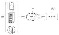
도 1에 도시된 바와 같이, 본 발명의 일 실시예에 따른 전체 시스템은 통신망(100), 산출 시스템(200) 및 영상 모듈(300)을 포함하여 구성될 수 있다.As shown in FIG. 1, the entire system according to an embodiment of the present invention may include a
먼저, 본 발명의 일 실시예에 따른 통신망(100)은 유선 통신이나 무선 통신과 같은 통신 양태를 가리지 않고 구성될 수 있으며, 근거리 통신망(LAN; Local Area Network), 도시권 통신망(MAN; Metropolitan Area Network), 광역 통신망(WAN; Wide Area Network) 등 다양한 통신망으로 구성될 수 있다. 바람직하게는, 본 명세서에서 말하는 통신망(100)은 공지의 인터넷 또는 월드와이드웹(WWW; World Wide Web)일 수 있다. 그러나, 통신망(100)은, 굳이 이에 국한될 필요 없이, 공지의 유무선 데이터 통신망, 공지의 전화망 또는 공지의 유무선 텔레비전 통신망을 그 적어도 일부에 있어서 포함할 수도 있다.First, the
예를 들면, 통신망(100)은 무선 데이터 통신망으로서, 무선 주파수(RF; Radio Frequency) 통신, 와이파이(WiFi) 통신, 셀룰러 통신(LTE 등), 블루투스 통신(더 구체적으로는, 저전력 블루투스(BLE; Bluetooth Low Energy) 통신), 적외선 통신, 초음파 통신 등과 같은 종래의 통신 방법을 적어도 그 일부분에 있어서 구현하는 것일 수 있다.For example, the
다음으로, 본 발명의 일 실시예에 따른 산출 시스템(200)은 메모리 수단을 구비하고 마이크로 프로세서를 탑재하여 연산 능력을 갖춘 디지털 디바이스일 수 있다. 이러한 산출 시스템(200)은 서버 시스템일 수 있다.Next, the
본 발명의 일 실시예에 따르면, 산출 시스템(200)은 후술할 하나의 영상 모듈(300)을 이용하여 피사체에 관한 적어도 세 개의 이미지를 획득할 수 있고, 이와 같은 적어도 세 개의 이미지를 참조하여, 영상 모듈(300)에 대향하여 존재하는 배경 상에서 영상 모듈(300)의 시점(view point)을 기준으로 하여 피사체에 대하여 투사하여 결정되는 적어도 세 개의 위치와 영상 모듈(300)이 배치되는 위치의 위치 관계에 기초하여 기준 공간 내에서의 피사체의 운동 궤적을 산출하는 기능을 수행할 수 있다.According to an embodiment of the present invention, the
본 발명의 일 실시예에 따른 기준 공간은, 산출 시스템(200)에서 기준으로 삼는 소정의 3차원 좌표계에서 정의되는 공간을 포함하는 개념일 수 있다.The reference space according to an embodiment of the present invention may be a concept including a space defined in a predetermined three-dimensional coordinate system as a reference in the
본 발명에 따른 산출 시스템(200)의 구성과 기능에 관하여는 아래에서 더 자세하게 알아보기로 한다. 한편, 산출 시스템(200)에 관하여 위와 같이 설명되었으나, 이러한 설명은 예시적인 것이고, 산출 시스템(200)에 요구되는 기능이나 구성요소의 적어도 일부가 필요에 따라 외부 시스템(미도시됨) 내에서 실현되거나 외부 시스템 내에 포함될 수도 있음은 당업자에게 자명하다.The configuration and function of the
다음으로, 본 발명의 일 실시예에 따른 영상 모듈(300)은 통신망(100)을 통하여 산출 시스템(200)과 연결될 수 있고, 소정의 시간이나 소정의 프레임의 간격으로 피사체를 촬영함으로써 피사체의 이미지를 획득하는 기능을 수행할 수 있다. 이와 같은 영상 모듈(300)에는, 2차원 또는 3차원 카메라, 적외선 또는 자외선 카메라 등이 포함될 수 있다.Next, the
산출 시스템의 구성Composition of calculation system
이하에서는, 본 발명의 구현을 위하여 중요한 기능을 수행하는 산출 시스템(200)의 내부 구성 및 각 구성요소의 기능에 대하여 살펴보기로 한다.Hereinafter, the internal configuration of the
도 2는 본 발명의 일 실시예에 따른 산출 시스템(200)의 내부 구성을 상세하게 도시하는 도면이다.2 is a view showing in detail the internal configuration of the
도 2에 도시된 바와 같이, 산출 시스템(200)은, 이미지 획득부(210), 궤적 산출부(220), 통신부(230) 및 제어부(240)를 포함하여 구성될 수 있다. 본 발명의 일 실시예에 따르면, 이미지 획득부(210), 궤적 산출부(220), 통신부(230) 및 제어부(240)는 그 중 적어도 일부가 영상 모듈(300)과 통신하는 프로그램 모듈일 수 있다. 이러한 프로그램 모듈은 운영 시스템, 응용 프로그램 모듈 또는 기타 프로그램 모듈의 형태로 산출 시스템(200)에 포함될 수 있고, 물리적으로는 여러 가지 공지의 기억 장치에 저장될 수 있다. 또한, 이러한 프로그램 모듈은 산출 시스템(200)과 통신 가능한 원격 기억 장치에 저장될 수도 있다. 한편, 이러한 프로그램 모듈은 본 발명에 따라 후술할 특정 업무를 수행하거나 특정 추상 데이터 유형을 실행하는 루틴, 서브루틴, 프로그램, 오브젝트, 컴포넌트, 데이터 구조 등을 포괄하지만, 이에 제한되지는 않는다.As shown in FIG. 2, the
먼저, 본 발명의 일 실시예에 따른 이미지 획득부(210)는 하나의 영상 모듈(300)을 이용하여 피사체에 관한 적어도 세 개의 이미지를 획득하는 기능을 수행할 수 있다.First, the
구체적으로, 이미지 획득부(210)는 하나의 영상 모듈(300)로부터 피사체의 이미지를 포함하는 적어도 세 개의 이미지를 소정의 시간이나 소정의 프레임의 간격으로 획득할 수 있다. 일 실시예에 따르면, 위와 같은 간격은 영상 모듈(300)의 촬영 주기(예를 들어, 1초당 프레임 수(FPS; Frame Per Second))에 기초하여 설정될 수 있다.Specifically, the
한편, 이미지 획득부(210)에 의하여 획득되는 피사체 이미지는 피사체가 운동하기 시작한 시점(timing)으로부터 충분히 짧은 시간(즉, 피사체의 속도가 그 최초의 속도로부터 아주 약간만 감소하는 데에 걸린 시간) 내에 획득된 이미지인 것이 바람직할 수 있다. 이 경우에, 편의상, 피사체는 직선 궤적을 갖고 운동하고, 그 궤적 내에서의 운동 속도는 모두 동일한 것으로 가정될 수 있다.On the other hand, the subject image acquired by the
다음으로, 본 발명의 일 실시예에 따른 궤적 산출부(220)는, 이미지 획득부(210)에 의하여 획득되는 적어도 세 개의 이미지를 참조하여, 영상 모듈(300)에 대향하여 존재하는 배경 상에서 영상 모듈(300)의 시점을 기준으로 하여 피사체에 대하여 투사하여 결정되는 적어도 세 개의 위치의 각각과 영상 모듈(300)이 배치된 위치를 지나는 적어도 세 개의 가상의 선에 기초하여 피사체의 운동 궤적을 산출하는 기능을 수행할 수 있다.Next, the
구체적으로, 궤적 산출부(220)는 위와 같은 적어도 세 개의 가상의 선 중 임의의 두 개로 이루어진 가상의 선 쌍(pair)을 적어도 두 개 결정하고, 그 결정되는 적어도 두 개의 가상 선 쌍 및 각 쌍에 대응되는 이미지 획득 시간 간격에 관한 정보에 기초하여 피사체의 운동 궤적을 산출할 수 있다. 예를 들면, 이미지 획득 시간 간격에 관한 정보는, 제1 가상의 선 및 제2 가상의 선으로 이루어진 쌍에 관하여는, 제1 가상의 선에 대응되는 이미지가 획득된 시점과 제2 가상의 선에 대응되는 이미지가 획득된 시점 사이의 간격일 수 있다.Specifically, the
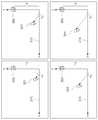
아래에서 도 3과 도 4를 더 참조하여 살펴보기로 한다. 도 3과 도 4는 본 발명의 일 실시예에 따라 피사체의 궤적이 산출되는 과정에 관한 개념도이다.Below with reference to Figures 3 and 4 will be described further. 3 and 4 are conceptual diagrams of a process in which a trajectory of a subject is calculated according to an embodiment of the present invention.
도 3과 도 4에 도시된 바와 같이, 영상 모듈(300)에 대향하여 존재하는 배경(310)과 그 배경(310)으로부터 영상 모듈(300)에 대하여 수직으로 향하는 직선을 각각 x축과 y축으로 간단히 도식화해 볼 수 있다. 이 경우에, 영상 모듈이 배치된 좌표(즉, (0,a))와 피사체가 운동을 시작하기 전에 있던 좌표(즉, (x0, 0))가 각각 설정될 수 있다.As shown in FIGS. 3 and 4, the x-axis and the y-axis represent the
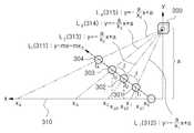
이미지 획득부(210)에 의하여, 동일한 시간 간격의 시점 t1, t2, t3 및 t4에서 제1 내지 제4 이미지(301, 302, 303, 304)가 각각 순서대로 획득될 수 있는데, 이에 따라, 궤적 산출부(200)는 제1 내지 제4 이미지(301, 302, 303, 304)에 해당하는 피사체의 운동 궤적을 가상의 직선 Lt(311)로 가정할 수 있다. 이러한 Lt(311)의 대응식은 y=mx-mx0와 같이 정해질 수 있다.The first to
한편, 제1 이미지(301)에서 영상 모듈(300)의 시점을 기준으로 하여 피사체에 대하여 투사하여 결정되는 배경 상의 위치와 영상 모듈(300)이 배치된 위치를 지나는 가상의 직선 L1(312)의 대응식을 y=-ax/x1+a로 정할 수 있고, 제2 이미지(302)에서 영상 모듈(300)의 시점을 기준으로 하여 피사체에 대하여 투사하여 결정되는 배경 상의 위치와 영상 모듈(300)이 배치된 위치를 지나는 가상의 직선 L2(313)의 대응식을 y=-ax/x2+a로 정할 수 있으며, 제3 이미지(303)에서 영상 모듈(300)의 시점을 기준으로 하여 피사체에 대하여 투사하여 결정되는 배경 상의 위치와 영상 모듈(300)이 배치된 위치를 지나는 가상의 직선 L3(314)의 대응식을 y=-ax/x3+a로 정할 수 있고, 제4 이미지(304)에서 영상 모듈(300)의 시점을 기준으로 하여 피사체에 대하여 투사하여 결정되는 배경 상의 위치와 영상 모듈(300)이 배치된 위치를 지나는 가상의 직선 L4(315)의 대응식을 y=-ax/x4+a로 정할 수 있다.Meanwhile, an imaginary straight line L1 312 passing through a position on a background determined by projecting a subject with respect to a subject based on the viewpoint of the
궤적 산출부(210)는 위의 네 개의 가상의 선, 즉, L1(312), L2(313), L3(314)및 L4(315) 중 임의의 두 개로 이루어진 가상 선 쌍을 적어도 두 개 선택할 수 있다. 예를 들면, L1(312)및 L2(313)의 쌍과 L2(313)및 L3(314)의 쌍을 선택할 수 있다. 이때, Lt(311)와 L1(312), L2(313) 및 L3(314) 각각 사이의 교점들의 x 좌표를 xp1=x0+(a-ax0/x1)/(m+a/x1), xp2=x0+(a-ax0/x2)/(m+a/x2) 및 xp3=x0+(a-ax0/x3)/(m+a/x3)로 각각 산출할 수 있다. L1(312)및 L2(313)의 쌍에 대응하는 시간 간격과 L2(313)및 L3(314)의 쌍에 대응하는 시간 간격이 모두 동일하므로, xp1와 xp2 사이의 거리는 xp2와 xp3 사이의 거리와 같게 되고, 이를 통해 궤적 산출부(200)는 m을 산출할 수 있다. 이에 따라, 궤적 산출부(200)는 Lt(311)를 산출할 수 있게 되므로, 결국 피사체의 운동 궤적이 산출될 수 있게 된다.The
이상에서는, 편의상, 가상 선 쌍들에 대응되는 시간 간격이 동일한 경우를 설명하였으나, xp1과 xp2 사이의 거리 및 xp2와 xp3 사이의 거리의 비가 제1 이미지(301)가 획득된 시점과 제2 이미지(302)가 획득된 시점 간의 시간 간격 그리고 제2 이미지(302)가 획득된 시점과 제3 이미지(303)가 획득된 시점 간의 시간 간격의 비와 동일하다고 정함으로써, 가상 선 쌍들에 대응되는 시간 간격이 상이한 경우에도 피사체의 운동 궤적이 산출될 수 있다.In the above, for convenience, the case where the time intervals corresponding to the virtual line pairs are the same has been described, but the ratio of the distance between xp1 and xp2 and the distance between xp2 and xp3 is the same as when the
한편, 위의 실시예에서는 피사체의 운동 궤적이 산출되는 과정을 2차원적으로 분석하여 설명하였지만, 이러한 과정을 1차원적으로 축소하여 분석하거나 3차원적으로 확장하여 분석하는 등 본 발명의 목적을 달성할 수 있는 범위 내에서 얼마든지 다른 분석 방법이 채용될 수 있다.On the other hand, in the above embodiment, the process in which the motion trajectory of the subject is calculated has been described in two dimensions, but the purpose of the present invention is to analyze such a process by reducing it in one dimension or by expanding it in three dimensions. Any other analytical method can be employed to the extent that can be achieved.
또한, 궤적 산출부(220)는, 위에서와 같이 산출되는 피사체의 운동 궤적과 영상 모듈(300)의 촬영의 시간 간격을 참조하여, 피사체의 운동 방향 및/또는 운동 속도를 산출할 수도 있다. 예를 들어, 궤적 산출부(220)는 피사체의 운동 궤적 내에서 특정되는 좌표들 사이의 거리를, 그 특정되는 좌표들에 대응되는 영상 모듈(300)의 촬영 시간 간격으로 나누어 피사체의 운동 속도를 쉽게 산출할 수 있다.In addition, the
다음으로, 본 발명의 일 실시예에 따른 통신부(230)는 이미지 획득부(210) 및 궤적 산출부(220)로부터의/로의 데이터 송수신이 가능하도록 하는 기능을 수행할 수 있다.Next, the
마지막으로, 본 발명의 일 실시예에 따른 제어부(240)는 이미지 획득부(210), 궤적 산출부(220) 및 통신부(230) 간의 데이터의 흐름을 제어하는 기능을 수행할 수 있다. 즉, 본 발명에 따른 제어부(240)는 산출 시스템(200)의 외부로부터의/로의 데이터 흐름 또는 산출 시스템(200)의 각 구성요소 간의 데이터 흐름을 제어함으로써, 이미지 획득부(210), 궤적 산출부(220) 및 통신부(230)에서 각각 고유 기능을 수행하도록 제어할 수 있다.Finally, the
도 5는 본 발명의 일 실시예에 따른 산출 시스템(200)이 외부 시스템에 적용되는 상황을 예시적으로 나타내는 도면이다.5 is a diagram illustrating a situation in which the
도 5에 도시된 바와 같이, 본 발명의 일 실시예에 따른 산출 시스템(200)이 종래의 가상 골프 시뮬레이션 시스템(400)에 포함되는 경우를 가정해 볼 수 있다. 이 경우에, 피사체는 골프 공일 수 있다.As illustrated in FIG. 5, it may be assumed that the
먼저, 사용자가 골프 채를 이용하여 타격 존에 있는 골프 공(501)을 타격하게 되면, 가상 골프 시뮬레이션 시스템(400)은 하나의 카메라(300)만을 이용하여 골프 공을 포함하는 세 개의 이미지를 획득할 수 있다.First, when a user hits a
그 다음에, 가상 골프 시뮬레이션 시스템(400)은, 위의 획득되는 이미지들을 참조하여, 카메라(300)에 대향하여 존재하는 배경(310) 상에서 카메라(300)의 시점을 기준으로 하여 골프 공에 대하여 투사하여 결정되는 세 개의 위치의 각각과 카메라(300)가 배치된 위치를 지나는 세 개의 가상의 선(510, 520, 530)에 기초하여 골프 공의 운동 궤적을 산출할 수 있다.Then, the virtual
그 다음에, 가상 골프 시뮬레이션 시스템(400)은 위의 산출되는 운동 궤적에 기초하여 골프 공의 운동 방향, 운동 속도 등에 관한 정보를 산출할 수 있고, 그 산출되는 정보를 기반으로 하여 골프 공의 운동에 관한 시뮬레이션을 수행할 수 있으며, 그 시뮬레이션 결과를 디스플레이(미도시됨)를 통하여 제공할 수 있다.Subsequently, the virtual
이상 설명된 본 발명에 따른 실시예는 다양한 컴퓨터 구성요소를 통하여 실행될 수 있는 프로그램 명령어의 형태로 구현되어 컴퓨터 판독 가능한 기록 매체에 기록될 수 있다. 상기 컴퓨터 판독 가능한 기록 매체는 프로그램 명령어, 데이터 파일, 데이터 구조 등을 단독으로 또는 조합하여 포함할 수 있다. 상기 컴퓨터 판독 가능한 기록 매체에 기록되는 프로그램 명령어는 본 발명을 위하여 특별히 설계되고 구성된 것이거나 컴퓨터 소프트웨어 분야의 당업자에게 공지되어 사용 가능한 것일 수 있다. 컴퓨터 판독 가능한 기록 매체의 예에는, 하드 디스크, 플로피 디스크 및 자기 테이프와 같은 자기 매체, CD-ROM 및 DVD와 같은 광기록 매체, 플롭티컬 디스크(floptical disk)와 같은 자기-광 매체(magneto-optical medium), 및 ROM, RAM, 플래시 메모리 등과 같은, 프로그램 명령어를 저장하고 실행하도록 특별히 구성된 하드웨어 장치가 포함된다. 프로그램 명령어의 예에는, 컴파일러에 의하여 만들어지는 것과 같은 기계어 코드뿐만 아니라 인터프리터 등을 사용하여 컴퓨터에 의해서 실행될 수 있는 고급 언어 코드도 포함된다. 하드웨어 장치는 본 발명에 따른 처리를 수행하기 위하여 하나 이상의 소프트웨어 모듈로 변경될 수 있으며, 그 역도 마찬가지이다.The embodiments according to the present invention described above may be implemented in the form of program instructions that can be executed through various computer components and can be recorded in a computer-readable recording medium. The computer-readable recording medium may include program instructions, data files, data structures, or the like alone or in combination. The program instructions recorded on the computer-readable recording medium may be specially designed and configured for the present invention or may be known and usable by those skilled in the computer software field. Examples of computer-readable recording media include magnetic media such as hard disks, floppy disks, and magnetic tapes, optical recording media such as CD-ROMs and DVDs, and magneto-optical media such as floptical disks. medium), and hardware devices specifically configured to store and execute program instructions, such as ROM, RAM, flash memory, and the like. Examples of program instructions include not only machine language codes produced by a compiler, but also high-level language codes executable by a computer using an interpreter or the like. The hardware device can be changed to one or more software modules to perform the processing according to the present invention, and vice versa.
이상에서 본 발명이 구체적인 구성요소 등과 같은 특정 사항과 한정된 실시예 및 도면에 의하여 설명되었으나, 이는 본 발명의 보다 전반적인 이해를 돕기 위하여 제공된 것일 뿐, 본 발명이 상기 실시예에 한정되는 것은 아니며, 본 발명이 속하는 기술분야에서 통상적인 지식을 가진 자라면 이러한 기재로부터 다양한 수정과 변경을 꾀할 수 있다.In the above, the present invention has been described by specific matters such as specific components and limited examples and drawings, but it is provided to help a more comprehensive understanding of the present invention, and the present invention is not limited to the above embodiments, and Those skilled in the art to which the invention pertains may seek various modifications and changes from these descriptions.
따라서, 본 발명의 사상은 상기 설명된 실시예에 국한되어 정해져서는 아니 되며, 후술하는 특허청구범위뿐만 아니라 이 특허청구범위와 균등한 또는 이로부터 등가적으로 변경된 모든 범위는 본 발명의 사상의 범주에 속한다고 할 것이다.Therefore, the spirit of the present invention is not limited to the above-described embodiment, and should not be determined, and the scope of the spirit of the present invention, as well as the claims to be described later, as well as all ranges that are equivalent to or equivalently changed from the claims. Would belong to
100: 통신망
200: 산출 시스템
210: 이미지 획득부
220: 궤적 산출부
230: 통신부
240: 제어부
300: 영상 모듈100: communication network
200: output system
210: image acquisition unit
220: trajectory calculator
230: Communication Department
240: control unit
300: video module
Claims (11)
Translated fromKorean하나의 영상 모듈을 이용하여 상기 피사체에 관한 적어도 세 개의 이미지를 획득하는 단계, 및
상기 적어도 세 개의 획득된 이미지를 참조하여, 배경 상에서 상기 하나의 영상 모듈의 시점을 기준으로 하여 상기 피사체에 대하여 투사하여 결정되는 적어도 세 개의 위치의 각각과, 상기 하나의 영상 모듈이 배치된 위치를 지나는 적어도 세 개의 가상의 선에 기초하여, 상기 피사체의 운동 궤적을 산출하는 단계
를 포함하는 방법.As a method for calculating the motion trajectory of the subject,
Acquiring at least three images of the subject using one image module, and
With reference to the at least three acquired images, each of at least three positions determined by projecting with respect to the subject based on a viewpoint of the one image module on a background and a position where the one image module is disposed Calculating a motion trajectory of the subject based on at least three virtual lines passing through
How to include.
상기 이미지 획득 단계에서, 상기 적어도 세 개의 이미지는 소정의 시간이나 소정의 프레임의 간격으로 획득되는
방법.According to claim 1,
In the image acquiring step, the at least three images are acquired at a predetermined time or a predetermined frame interval
Way.
상기 운동 궤적 산출 단계는, 상기 적어도 세 개의 가상의 선 중 임의의 두 개로 이루어진 가상의 선 쌍을 적어도 두 개 결정하는 단계를 포함하는
방법.According to claim 1,
The calculating of the motion trajectory includes determining at least two virtual line pairs consisting of any two of the at least three virtual lines.
Way.
상기 운동 궤적 산출 단계는, 상기 적어도 두 개의 가상 선 쌍에 대응되는 이미지 획득 시간 간격에 관한 정보에 기초하여 수행되는
방법.According to claim 3,
The calculating the motion trajectory is performed based on information on an image acquisition time interval corresponding to the at least two virtual line pairs.
Way.
상기 피사체의 상기 산출되는 운동 궤적 내에서 특정되는 좌표들 사이의 거리를, 그 특정되는 좌표들에 대응되는 상기 하나의 영상 모듈의 촬영 시간 간격으로 나누어, 상기 피사체의 운동 속도를 산출하는 단계
를 더 포함하는 방법.According to claim 1,
Calculating a movement speed of the subject by dividing a distance between coordinates specified in the calculated motion trajectory of the subject by a shooting time interval of the one image module corresponding to the specified coordinates
How to include more.
하나의 영상 모듈,
상기 하나의 영상 모듈을 이용하여 상기 피사체에 관한 적어도 세 개의 이미지를 획득하는 이미지 획득부, 및
상기 적어도 세 개의 획득된 이미지를 참조하여, 배경 상에서 상기 하나의 영상 모듈의 시점을 기준으로 하여 상기 피사체에 대하여 투사하여 결정되는 적어도 세 개의 위치의 각각과, 상기 하나의 영상 모듈이 배치된 위치를 지나는 적어도 세 개의 가상의 선에 기초하여, 상기 피사체의 운동 궤적을 산출하는 궤적 산출부
를 포함하는 시스템.A system for calculating the motion trajectory of a subject,
One video module,
An image acquisition unit for acquiring at least three images of the subject using the one image module, and
With reference to the at least three acquired images, each of at least three positions determined by projecting with respect to the subject based on a viewpoint of the one image module on a background and a position where the one image module is disposed A trajectory calculating unit that calculates a movement trajectory of the subject based on at least three virtual lines passing through
System comprising a.
상기 이미지 획득부에서, 상기 적어도 세 개의 이미지는 소정의 시간이나 소정의 프레임의 간격으로 획득되는
시스템.The method of claim 7,
In the image acquisition unit, the at least three images are acquired at a predetermined time or a predetermined frame interval
system.
상기 궤적 산출부는, 상기 적어도 세 개의 가상의 선 중 임의의 두 개로 이루어진 가상의 선 쌍을 적어도 두 개 결정하는
시스템.The method of claim 7,
The trajectory calculating unit determines at least two virtual line pairs made of any two of the at least three virtual lines.
system.
상기 궤적 산출부는, 상기 적어도 두 개의 가상 선 쌍에 대응되는 이미지 획득 시간 간격에 관한 정보를 이용하는
시스템.The method of claim 9,
The trajectory calculating unit uses information regarding an image acquisition time interval corresponding to the at least two virtual line pairs
system.
상기 궤적 산출부는, 상기 피사체의 상기 산출되는 운동 궤적 내에서 특정되는 좌표들 사이의 거리를, 그 특정되는 좌표들에 대응되는 상기 하나의 영상 모듈의 촬영 시간 간격으로 나누어, 상기 피사체의 운동 속도를 산출하는
시스템.The method of claim 7,
The trajectory calculating unit divides a distance between coordinates specified in the calculated motion trajectory of the subject by a shooting time interval of the one image module corresponding to the specified coordinates, and divides the movement speed of the subject Yielding
system.
Priority Applications (4)
| Application Number | Priority Date | Filing Date | Title |
|---|---|---|---|
| KR1020180130225AKR102125432B1 (en) | 2018-10-29 | 2018-10-29 | Method, system and non-transitory computer-readable recording medium for calculating a motion locus of a subject |
| JP2019194941AJP6920392B2 (en) | 2018-10-29 | 2019-10-28 | Methods, systems and non-transient computer-readable recording media for calculating the motion trajectory of a subject |
| CN201911036508.6ACN111192287B (en) | 2018-10-29 | 2019-10-29 | Method, system and storage medium for calculating movement track of shooting object |
| US16/666,687US10997735B2 (en) | 2018-10-29 | 2019-10-29 | Method, system and non-transitory computer-readable recording medium for calculating a motion locus of a subject |
Applications Claiming Priority (1)
| Application Number | Priority Date | Filing Date | Title |
|---|---|---|---|
| KR1020180130225AKR102125432B1 (en) | 2018-10-29 | 2018-10-29 | Method, system and non-transitory computer-readable recording medium for calculating a motion locus of a subject |
Publications (2)
| Publication Number | Publication Date |
|---|---|
| KR20200048284Atrue KR20200048284A (en) | 2020-05-08 |
| KR102125432B1 KR102125432B1 (en) | 2020-06-23 |
Family
ID=70325488
Family Applications (1)
| Application Number | Title | Priority Date | Filing Date |
|---|---|---|---|
| KR1020180130225AActiveKR102125432B1 (en) | 2018-10-29 | 2018-10-29 | Method, system and non-transitory computer-readable recording medium for calculating a motion locus of a subject |
Country Status (4)
| Country | Link |
|---|---|
| US (1) | US10997735B2 (en) |
| JP (1) | JP6920392B2 (en) |
| KR (1) | KR102125432B1 (en) |
| CN (1) | CN111192287B (en) |
Families Citing this family (1)
| Publication number | Priority date | Publication date | Assignee | Title |
|---|---|---|---|---|
| US12434102B1 (en) | 2025-05-14 | 2025-10-07 | Gpro Co., Ltd. | Ball launch analysis device and ball launch analysis method |
Citations (3)
| Publication number | Priority date | Publication date | Assignee | Title |
|---|---|---|---|---|
| KR20020005580A (en)* | 1999-01-29 | 2002-01-17 | 오서피딕 시스템즈 아이엔씨. | Golf ball flight monitoring system |
| KR20130032857A (en)* | 2011-09-23 | 2013-04-02 | 주식회사 크리에이츠 | Method and system for photographing object in movement with plural camera, and based on taken images therefor, obtaining actual movement trace of same object |
| KR20140074577A (en)* | 2012-12-10 | 2014-06-18 | 한국전자통신연구원 | Method for tuning trajectory model of ball and apparatus thereof |
Family Cites Families (9)
| Publication number | Priority date | Publication date | Assignee | Title |
|---|---|---|---|---|
| CA2740109C (en)* | 2008-10-08 | 2016-01-19 | Interactive Sports Technologies Inc. | Sports simulation system |
| CN101894366B (en)* | 2009-05-21 | 2014-01-29 | 北京中星微电子有限公司 | Method and device for acquiring calibration parameters and video monitoring system |
| WO2011106888A1 (en)* | 2010-03-05 | 2011-09-09 | Interactive Sports Technologies Inc. | Apparatus and method for measuring golf club shaft flex and golf simulation system incorporating the same |
| US20110250939A1 (en)* | 2010-04-09 | 2011-10-13 | Hobler Marc L | Network-connected golf game improvement, entertainment and monetization system and method |
| US8948457B2 (en)* | 2013-04-03 | 2015-02-03 | Pillar Vision, Inc. | True space tracking of axisymmetric object flight using diameter measurement |
| CN104484883A (en)* | 2014-12-24 | 2015-04-01 | 河海大学常州校区 | Video-based three-dimensional virtual ship positioning and track simulation method |
| CN105225229B (en)* | 2015-09-07 | 2017-09-05 | 三峡大学 | Device and method for locating fish trajectories over dams based on video signals |
| CN106033615B (en)* | 2016-05-16 | 2017-09-15 | 北京旷视科技有限公司 | Destination object motion direction detecting method and device |
| KR101826837B1 (en)* | 2016-08-12 | 2018-02-08 | 주식회사 골프존 | Device for calculating information on flight of ball, method for the same and recording medium recording the method readable by computing device |
- 2018
- 2018-10-29KRKR1020180130225Apatent/KR102125432B1/enactiveActive
- 2019
- 2019-10-28JPJP2019194941Apatent/JP6920392B2/enactiveActive
- 2019-10-29CNCN201911036508.6Apatent/CN111192287B/enactiveActive
- 2019-10-29USUS16/666,687patent/US10997735B2/enactiveActive
Patent Citations (4)
| Publication number | Priority date | Publication date | Assignee | Title |
|---|---|---|---|---|
| KR20020005580A (en)* | 1999-01-29 | 2002-01-17 | 오서피딕 시스템즈 아이엔씨. | Golf ball flight monitoring system |
| KR20130032857A (en)* | 2011-09-23 | 2013-04-02 | 주식회사 크리에이츠 | Method and system for photographing object in movement with plural camera, and based on taken images therefor, obtaining actual movement trace of same object |
| KR20130032858A (en)* | 2011-09-23 | 2013-04-02 | 주식회사 크리에이츠 | Method and system for photographing object in movement with camera, and based on taken images therefor, obtaining actual movement trace of same object |
| KR20140074577A (en)* | 2012-12-10 | 2014-06-18 | 한국전자통신연구원 | Method for tuning trajectory model of ball and apparatus thereof |
Also Published As
| Publication number | Publication date |
|---|---|
| CN111192287A (en) | 2020-05-22 |
| US20200134842A1 (en) | 2020-04-30 |
| JP2020071228A (en) | 2020-05-07 |
| JP6920392B2 (en) | 2021-08-18 |
| US10997735B2 (en) | 2021-05-04 |
| KR102125432B1 (en) | 2020-06-23 |
| CN111192287B (en) | 2023-11-24 |
Similar Documents
| Publication | Publication Date | Title |
|---|---|---|
| US9448067B2 (en) | System and method for photographing moving subject by means of multiple cameras, and acquiring actual movement trajectory of subject based on photographed images | |
| US10467478B2 (en) | System and method for mobile feedback generation using video processing and object tracking | |
| JP7051315B2 (en) | Methods, systems, and non-temporary computer-readable recording media for measuring ball rotation. | |
| US10083519B2 (en) | Information processing apparatus and information processing method for specifying a composition of a picture | |
| CN107168532A (en) | A kind of virtual synchronous display methods and system based on augmented reality | |
| US10406413B2 (en) | Analysis apparatus, analysis method, and recording medium | |
| CN103971399A (en) | Street view image transition method and device | |
| JP2020095019A (en) | Method, system and non-transitory computer readable recording medium for measuring ball rotation | |
| KR102125432B1 (en) | Method, system and non-transitory computer-readable recording medium for calculating a motion locus of a subject | |
| US10776929B2 (en) | Method, system and non-transitory computer-readable recording medium for determining region of interest for photographing ball images | |
| AU2024216420A1 (en) | Method, system, and non-transitory computer readable storage medium for supporting virtual golf simulation | |
| KR102129129B1 (en) | Method, system and non-transitory computer-readable recording medium for measuring ball spin | |
| JP6381092B2 (en) | Method and apparatus for estimating the value of an input in the presence of a perturbation factor | |
| CN104994307B (en) | A kind of method for correcting image and device | |
| KR20160139634A (en) | Golf ball spin calculation method and apparatus | |
| KR102443281B1 (en) | Method, system and non-transitory computer-readable recording medium for compensating brightness of ball images | |
| KR20220128599A (en) | Method, system and non-transitory computer-readable recording medium for compensating brightness of ball images | |
| KR20250095428A (en) | Method and system for determining alignment information for golf shot analysis | |
| KR20250108358A (en) | Method and apparatus for analyzing golf swing motion using artificial intelligence model for screen golf | |
| CN114681886A (en) | Golf swing analysis system, golf swing analysis method, and information storage medium | |
| WO2016051021A1 (en) | Determination of at least one parameter relating to a trajectory of an object | |
| KR20150094798A (en) | Method for adjusting roration of cemara using orientation sensor |
Legal Events
| Date | Code | Title | Description |
|---|---|---|---|
| PA0109 | Patent application | Patent event code:PA01091R01D Comment text:Patent Application Patent event date:20181029 | |
| PA0201 | Request for examination | ||
| PE0902 | Notice of grounds for rejection | Comment text:Notification of reason for refusal Patent event date:20191018 Patent event code:PE09021S01D | |
| PG1501 | Laying open of application | ||
| E701 | Decision to grant or registration of patent right | ||
| PE0701 | Decision of registration | Patent event code:PE07011S01D Comment text:Decision to Grant Registration Patent event date:20200605 | |
| GRNT | Written decision to grant | ||
| PR0701 | Registration of establishment | Comment text:Registration of Establishment Patent event date:20200616 Patent event code:PR07011E01D | |
| PR1002 | Payment of registration fee | Payment date:20200617 End annual number:3 Start annual number:1 | |
| PG1601 | Publication of registration | ||
| PR1001 | Payment of annual fee | Payment date:20240603 Start annual number:5 End annual number:5 | |
| PR1001 | Payment of annual fee | Payment date:20250403 Start annual number:6 End annual number:6 |