KR20200046754A - Secondary battery for solar lighting system and solar lighting system utilizing the same - Google Patents
Secondary battery for solar lighting system and solar lighting system utilizing the sameDownload PDFInfo
- Publication number
- KR20200046754A KR20200046754AKR1020180128330AKR20180128330AKR20200046754AKR 20200046754 AKR20200046754 AKR 20200046754AKR 1020180128330 AKR1020180128330 AKR 1020180128330AKR 20180128330 AKR20180128330 AKR 20180128330AKR 20200046754 AKR20200046754 AKR 20200046754A
- Authority
- KR
- South Korea
- Prior art keywords
- secondary battery
- lighting system
- solar
- head
- solar lighting
- Prior art date
- Legal status (The legal status is an assumption and is not a legal conclusion. Google has not performed a legal analysis and makes no representation as to the accuracy of the status listed.)
- Granted
Links
Images


Classifications
- H—ELECTRICITY
- H01—ELECTRIC ELEMENTS
- H01M—PROCESSES OR MEANS, e.g. BATTERIES, FOR THE DIRECT CONVERSION OF CHEMICAL ENERGY INTO ELECTRICAL ENERGY
- H01M50/00—Constructional details or processes of manufacture of the non-active parts of electrochemical cells other than fuel cells, e.g. hybrid cells
- H01M50/20—Mountings; Secondary casings or frames; Racks, modules or packs; Suspension devices; Shock absorbers; Transport or carrying devices; Holders
- H01M2/1077—
- F—MECHANICAL ENGINEERING; LIGHTING; HEATING; WEAPONS; BLASTING
- F21—LIGHTING
- F21S—NON-PORTABLE LIGHTING DEVICES; SYSTEMS THEREOF; VEHICLE LIGHTING DEVICES SPECIALLY ADAPTED FOR VEHICLE EXTERIORS
- F21S8/00—Lighting devices intended for fixed installation
- F21S8/08—Lighting devices intended for fixed installation with a standard
- F21S8/085—Lighting devices intended for fixed installation with a standard of high-built type, e.g. street light
- F21S8/086—Lighting devices intended for fixed installation with a standard of high-built type, e.g. street light with lighting device attached sideways of the standard, e.g. for roads and highways
- F—MECHANICAL ENGINEERING; LIGHTING; HEATING; WEAPONS; BLASTING
- F21—LIGHTING
- F21S—NON-PORTABLE LIGHTING DEVICES; SYSTEMS THEREOF; VEHICLE LIGHTING DEVICES SPECIALLY ADAPTED FOR VEHICLE EXTERIORS
- F21S9/00—Lighting devices with a built-in power supply; Systems employing lighting devices with a built-in power supply
- F21S9/02—Lighting devices with a built-in power supply; Systems employing lighting devices with a built-in power supply the power supply being a battery or accumulator
- F21S9/03—Lighting devices with a built-in power supply; Systems employing lighting devices with a built-in power supply the power supply being a battery or accumulator rechargeable by exposure to light
- F21S9/032—Lighting devices with a built-in power supply; Systems employing lighting devices with a built-in power supply the power supply being a battery or accumulator rechargeable by exposure to light the solar unit being separate from the lighting unit
- H—ELECTRICITY
- H01—ELECTRIC ELEMENTS
- H01M—PROCESSES OR MEANS, e.g. BATTERIES, FOR THE DIRECT CONVERSION OF CHEMICAL ENERGY INTO ELECTRICAL ENERGY
- H01M10/00—Secondary cells; Manufacture thereof
- H01M10/42—Methods or arrangements for servicing or maintenance of secondary cells or secondary half-cells
- H01M10/425—Structural combination with electronic components, e.g. electronic circuits integrated to the outside of the casing
- H01M10/4257—Smart batteries, e.g. electronic circuits inside the housing of the cells or batteries
- H—ELECTRICITY
- H02—GENERATION; CONVERSION OR DISTRIBUTION OF ELECTRIC POWER
- H02S—GENERATION OF ELECTRIC POWER BY CONVERSION OF INFRARED RADIATION, VISIBLE LIGHT OR ULTRAVIOLET LIGHT, e.g. USING PHOTOVOLTAIC [PV] MODULES
- H02S10/00—PV power plants; Combinations of PV energy systems with other systems for the generation of electric power
- F—MECHANICAL ENGINEERING; LIGHTING; HEATING; WEAPONS; BLASTING
- F21—LIGHTING
- F21W—INDEXING SCHEME ASSOCIATED WITH SUBCLASSES F21K, F21L, F21S and F21V, RELATING TO USES OR APPLICATIONS OF LIGHTING DEVICES OR SYSTEMS
- F21W2131/00—Use or application of lighting devices or systems not provided for in codes F21W2102/00-F21W2121/00
- F21W2131/10—Outdoor lighting
- F21W2131/103—Outdoor lighting of streets or roads
- H—ELECTRICITY
- H01—ELECTRIC ELEMENTS
- H01M—PROCESSES OR MEANS, e.g. BATTERIES, FOR THE DIRECT CONVERSION OF CHEMICAL ENERGY INTO ELECTRICAL ENERGY
- H01M10/00—Secondary cells; Manufacture thereof
- H01M10/42—Methods or arrangements for servicing or maintenance of secondary cells or secondary half-cells
- H01M10/425—Structural combination with electronic components, e.g. electronic circuits integrated to the outside of the casing
- H01M2010/4271—Battery management systems including electronic circuits, e.g. control of current or voltage to keep battery in healthy state, cell balancing
- H—ELECTRICITY
- H01—ELECTRIC ELEMENTS
- H01M—PROCESSES OR MEANS, e.g. BATTERIES, FOR THE DIRECT CONVERSION OF CHEMICAL ENERGY INTO ELECTRICAL ENERGY
- H01M2220/00—Batteries for particular applications
- H01M2220/10—Batteries in stationary systems, e.g. emergency power source in plant
- Y—GENERAL TAGGING OF NEW TECHNOLOGICAL DEVELOPMENTS; GENERAL TAGGING OF CROSS-SECTIONAL TECHNOLOGIES SPANNING OVER SEVERAL SECTIONS OF THE IPC; TECHNICAL SUBJECTS COVERED BY FORMER USPC CROSS-REFERENCE ART COLLECTIONS [XRACs] AND DIGESTS
- Y02—TECHNOLOGIES OR APPLICATIONS FOR MITIGATION OR ADAPTATION AGAINST CLIMATE CHANGE
- Y02B—CLIMATE CHANGE MITIGATION TECHNOLOGIES RELATED TO BUILDINGS, e.g. HOUSING, HOUSE APPLIANCES OR RELATED END-USER APPLICATIONS
- Y02B20/00—Energy efficient lighting technologies, e.g. halogen lamps or gas discharge lamps
- Y02B20/72—Energy efficient lighting technologies, e.g. halogen lamps or gas discharge lamps in street lighting
- Y—GENERAL TAGGING OF NEW TECHNOLOGICAL DEVELOPMENTS; GENERAL TAGGING OF CROSS-SECTIONAL TECHNOLOGIES SPANNING OVER SEVERAL SECTIONS OF THE IPC; TECHNICAL SUBJECTS COVERED BY FORMER USPC CROSS-REFERENCE ART COLLECTIONS [XRACs] AND DIGESTS
- Y02—TECHNOLOGIES OR APPLICATIONS FOR MITIGATION OR ADAPTATION AGAINST CLIMATE CHANGE
- Y02E—REDUCTION OF GREENHOUSE GAS [GHG] EMISSIONS, RELATED TO ENERGY GENERATION, TRANSMISSION OR DISTRIBUTION
- Y02E10/00—Energy generation through renewable energy sources
- Y02E10/50—Photovoltaic [PV] energy
- Y—GENERAL TAGGING OF NEW TECHNOLOGICAL DEVELOPMENTS; GENERAL TAGGING OF CROSS-SECTIONAL TECHNOLOGIES SPANNING OVER SEVERAL SECTIONS OF THE IPC; TECHNICAL SUBJECTS COVERED BY FORMER USPC CROSS-REFERENCE ART COLLECTIONS [XRACs] AND DIGESTS
- Y02—TECHNOLOGIES OR APPLICATIONS FOR MITIGATION OR ADAPTATION AGAINST CLIMATE CHANGE
- Y02E—REDUCTION OF GREENHOUSE GAS [GHG] EMISSIONS, RELATED TO ENERGY GENERATION, TRANSMISSION OR DISTRIBUTION
- Y02E60/00—Enabling technologies; Technologies with a potential or indirect contribution to GHG emissions mitigation
- Y02E60/10—Energy storage using batteries
Landscapes
- Engineering & Computer Science (AREA)
- General Engineering & Computer Science (AREA)
- Chemical & Material Sciences (AREA)
- Chemical Kinetics & Catalysis (AREA)
- Electrochemistry (AREA)
- General Chemical & Material Sciences (AREA)
- Microelectronics & Electronic Packaging (AREA)
- Manufacturing & Machinery (AREA)
- Life Sciences & Earth Sciences (AREA)
- Sustainable Development (AREA)
- Non-Portable Lighting Devices Or Systems Thereof (AREA)
- Photovoltaic Devices (AREA)
Abstract
Description
Translated fromKorean본 발명은 태양광 라이팅 시스템용 이차 전지 및 이를 이용한 태양광 라이팅 시스템에 관한 것으로서, 이차 전지 팩이 라이팅 헤드에 밀봉 내장되는 구조를 가진 태양광 라이팅 시스템용 이차 전지 및 이를 이용한 태양광 라이팅 시스템에 관한 것이다.The present invention relates to a secondary battery for a solar lighting system and a solar lighting system using the same, wherein the secondary battery pack has a structure in which the secondary battery pack is sealed and embedded in the secondary lighting system and a solar lighting system using the secondary battery will be.
일반적으로, 가로등, 보안등과 같은 라이팅 시스템은 야간의 교통, 보행의 안전과 보안을 위하여 길가를 따라 설치된다. 또한, 통상적인 라이팅 시스템은 라이팅 시스템의 폴(pole)의 형식에 따라 하이웨이형, 브라켓형, 주두형 등이 있으며, 광원으로는 고압수은등, 나트륨등, 메탈할라이드 램프, CDM 등이 이용된다.In general, lighting systems such as street lights and security lights are installed along roadsides for night traffic and pedestrian safety and security. In addition, conventional lighting systems include a highway type, a bracket type, and a head type depending on the type of pole of the lighting system, and a high pressure mercury lamp, sodium lamp, metal halide lamp, CDM, etc. are used as a light source.
그러나 이러한 종류의 라이팅 시스템은 대부분이 광원의 전력 소비가 심하고, 수명이 짧아 유지 보수에 많은 시간과 비용이 소요되는 문제점이 있었다. 이러한 문제점을 해결하기 위하여 근래에는 밝기는 높고, 전력 소비량은 낮으면서 수명이 상대적으로 긴 LED 광원이 이용되고 있다. 한편, 라이팅 시스템의 광원에 전력을 공급하기 위해 솔라 패널을 이용하여 전력을 생산하고 그렇게 생산된 전력을 이차 전지에 저장하여 야간에 조명을 밝히는 태양광 라이팅 시스템이 존재한다.However, most of these types of lighting systems have a problem that the power consumption of the light source is severe and the service life is short, which takes a lot of time and money for maintenance. In order to solve this problem, in recent years, a LED light source having a high brightness, a low power consumption, and a relatively long lifetime has been used. On the other hand, there is a solar lighting system that generates power using a solar panel to supply power to a light source of a lighting system and stores the generated power in a secondary battery to illuminate at night.
그러나, 종래의 대부분의 태양광 라이팅 시스템의 경우, 이차 전지가 폴 내부 또는 별도의 단자함 내부에 설치되어 운영되고 있으며, 이차 전지의 용량이 부족하기 때문에 기존의 SOC 전력을 병행해서 이용하거나 디밍 장치 또는 센서를 이용하여 조명이 필요하지 않은 시간에 광원에 전력을 공급하지 않거나 공급량을 줄이는 방식으로 이차 전지의 적은 용량을 보완하는 방식을 채택하고 있는 실정이다. 한편, 이차 전지가 별도의 단자함에 설치되어 운용되는 경우, 단자함의 관리 소홀로 이차 전지가 도난의 대상이 되거나 파괴되는 등의 문제점도 있다.However, in the case of most conventional solar lighting systems, the secondary battery is installed and operated inside the pole or in a separate terminal box, and because the capacity of the secondary battery is insufficient, the existing SOC power is used in parallel or a dimming device or It is a situation in which a method of supplementing a small capacity of a secondary battery is adopted by not supplying power to a light source at a time when lighting is not required or by reducing a supply amount using a sensor. On the other hand, when the secondary battery is installed and operated in a separate terminal box, there is also a problem in that the secondary battery is subject to theft or is destroyed due to neglect of the management of the terminal box.
본 발명은 전술한 문제점들을 해결하기 위해 착상된 것으로서, 태양광 라이팅 시스템의 라이팅 헤드 내부에 밀봉 내장될 수 있는 구조를 가진 태양광 라이팅 시스템용 이차 전지 및 이를 이용한 태양광 라이팅 시스템을 제공하는 것을 목적으로 한다.The present invention has been conceived to solve the above-mentioned problems, and an object of the present invention is to provide a secondary battery for a solar lighting system having a structure that can be sealed and embedded inside a lighting head of a solar lighting system and a solar lighting system using the same. Is done.
상기 목적을 달성하기 위하여, 일 측면에 따른 태양광 라이팅 시스템용 이차 전지는, 전기적으로 연결되고 서로 적층된 다수의 파우치형 셀들이 조립된 셀 조립체를 바인딩할 수 있는 소프트 팩; 상기 소프트 팩이 수납될 수 있는 메인 박스; 및 상기 셀 조립체에 연결된 보호회로모듈을 수납할 수 있고 상기 메인 박스의 외벽면에 분리 가능하게 결합되는 서브 박스를 포함한다.In order to achieve the above object, a secondary battery for a solar lighting system according to an aspect includes: a soft pack capable of binding a cell assembly in which a plurality of pouch-shaped cells electrically connected and stacked with each other are assembled; A main box in which the soft pack can be stored; And a sub box that can receive a protection circuit module connected to the cell assembly and is detachably coupled to an outer wall surface of the main box.
바람직하게, 상기 메인 박스는: 상기 소프트 팩을 수납할 수 있는 수납부와 개방단을 구비하는 실질적으로 직육면체 형상의 메인 본체; 및 상기 메인 본체의 개방단에 결합될 수 있는 메인 커버를 구비한다.Preferably, the main box includes: a main body having a substantially rectangular parallelepiped shape having a storage portion and an open end capable of storing the soft pack; And a main cover that can be coupled to the open end of the main body.
바람직하게, 상기 메인 본체는 장변의 2개의 테두리들로부터 실질적으로 수직 방향 외측으로 각각 연장되는 2개의 메인 본체 결합부들을 구비하고; 상기 메인 커버는 상기 메인 본체 결합부가 접촉되어 결합될 수 있는 메인 커버 결합부, 및 상기 메인 커버 결합부로부터 연장되어 형성되는 메인 박스 설치부를 구비한다.Preferably, the main body has two main body coupling portions extending from the two edges of the long side outwards in a substantially vertical direction, respectively; The main cover includes a main cover coupling portion that can be coupled by contacting the main body coupling portion, and a main box installation portion extending from the main cover coupling portion.
바람직하게, 상기 메인 박스 설치부는: 상기 메인 커버의 적어도 하나의 모서리로부터 미리결정된 간격만큼 상기 메인 커버로부터 연장되는 이격 플랜지; 및 상기 이격 플랜지로부터 실질적으로 수직되게 외측으로 연장되고 태양광 라이딩 시스템의 헤드 본체에 접촉될 수 있도록 설치 구멍이 관통 형성된 베이스 플랜지를 구비한다.Preferably, the main box installation unit: a spaced flange extending from the main cover by a predetermined distance from at least one edge of the main cover; And a base flange extending substantially vertically outwardly from the spaced flange and having an installation hole through which it can contact the head body of the solar riding system.
바람직하게, 상기 2개의 메인 본체 결합부들 각각은 상응하는 상기 테두리로부터 연장하는 길이가 서로 상이하다.Preferably, each of the two main body coupling portions has a different length extending from the corresponding rim.
바람직하게, 상기 서브 박스는 상기 2개의 메인 본체 결합부들 중 연장 길이가 긴 부분의 메인 박스의 측면에 설치된다.Preferably, the sub box is installed on the side of the main box of the extended length of the two main body coupling portion.
바람직하게, 상기 서브 박스는, 상기 보호회로모듈을 관통하여 상기 메인 박스 표면에 고정될 수 있는 적어도 하나의 고정 부재를 더 구비한다.Preferably, the sub box is further provided with at least one fixing member that can be fixed to the surface of the main box through the protection circuit module.
상기 목적을 달성하기 위하여, 다른 측면에 따른 태양광 라이팅 시스템은, 태양광 패널; 상기 태양광 패널로부터 생산되는 전력을 저장할 수 있는 이차 전지가 밀봉 수납될 수 있는 밀봉 수납부, 및 상기 이차 전지로부터 선택적으로 전력을 공급받아 발광될 수 있는 발광부를 구비하는 라이팅 헤드; 및 상기 이차 전지 및/또는 상기 발광부 및/또는 상기 태양광 패널의 작동을 제어할 수 있도록 구성된 컨트롤러를 구비한다.In order to achieve the above object, a solar lighting system according to another aspect, a solar panel; A lighting head having a sealed storage unit in which a secondary battery capable of storing electric power produced from the solar panel can be sealed and stored, and a light emitting unit capable of selectively receiving power from the secondary battery and emitting light; And a controller configured to control the operation of the secondary battery and / or the light emitting unit and / or the solar panel.
바람직하게, 상기 컨트롤러는 상기 이차 전지와 함께 상기 밀봉 수납부에 수납될 수 있다.Preferably, the controller may be accommodated in the sealed storage unit together with the secondary battery.
바람직하게, 상기 라이팅 헤드는 헤드 본체와 헤드 커버를 포함하고; 상기 밀봉 수납부는, 상기 이차 전지가 수납될 수 있도록 상기 헤드 본체에 형성된 제1 수납부, 상기 컨트롤러가 수납될 수 있도록 상기 헤드 커버에 형성된 제2 수납부, 및 상기 제1 수납부와 상기 제2 수납부의 적어도 하나의 개방단에 마련 밀봉부재를 구비한다.Preferably, the lighting head includes a head body and a head cover; The sealed accommodating part, a first accommodating part formed in the head body so that the secondary battery can be accommodated, a second accommodating part formed in the head cover so that the controller can be accommodated, and the first accommodating part and the second A sealing member is provided on at least one open end of the storage unit.
바람직하게, 상기 제1 수납부는: 상기 태양광 패널에 연결될 수 있는 케이블이 밀봉 관통할 수 있는 제1 관통구; 및 상기 발광부에 연결될 수 있는 적어도 하나의 케이블이 밀봉 관통할 수 있는 제2 관통구를 구비한다.Preferably, the first storage unit includes: a first through-hole through which a cable that can be connected to the solar panel is sealed; And a second through hole through which at least one cable that can be connected to the light emitting portion is sealed.
바람직하게, 상기 헤드 커버는 상기 헤드 본체에 대해 힌지 결합될 수 있다.Preferably, the head cover may be hinged to the head body.
바람직하게, 상기 헤드 본체에 대해 상기 헤드 커버를 선택적으로 개방 또는 폐쇄하기 위한 클램핑 디바이스를 더 구비한다.Preferably, a clamping device for selectively opening or closing the head cover with respect to the head body is further provided.
바람직하게, 상기 발광부는 발광다이오드(LED) 모듈을 구비한다.Preferably, the light emitting unit includes a light emitting diode (LED) module.
바람직하게, 상기 이차 전지는, 전술한 태양광 라이팅 시스템의 이차 전지를 포함한다.Preferably, the secondary battery includes the secondary battery of the solar lighting system described above.
바람직하게, 상기 이차 전지는: 전기적으로 연결되고 서로 적층된 다수의 파우치형 셀들이 조립된 셀 조립체를 바인딩할 수 있는 소프트 팩; 상기 셀 조립체에 전기적으로 연결된 보호회로모듈; 및 상기 소프트 팩을 상기 밀봉 수납부에 부착시키기 위한 부착 부재를 포함한다.Preferably, the secondary battery includes: a soft pack capable of binding a cell assembly in which a plurality of pouch-shaped cells electrically connected and stacked on each other are assembled; A protection circuit module electrically connected to the cell assembly; And an attachment member for attaching the soft pack to the sealed housing.
바람직하게, 상기 부착 부재는: 상기 소프트 팩을 감싸는 적어도 하나의 밴드; 및 상기 밴드와 상기 밀봉 수납부 사이에 개재될 수 있는 접착테이프를 구비한다.Preferably, the attachment member comprises: at least one band surrounding the soft pack; And an adhesive tape that can be interposed between the band and the sealed housing.
바람직하게, 상기 태양광 패널은 지면에 고정된 가로등 또는 보안등의 폴(pole)에 설치되고; 상기 라이팅 헤드는 상기 등주로부터 연장되는 아암(arm)에 설치된다.Preferably, the solar panel is installed on a pole of a street light or security light fixed to the ground; The lighting head is installed on an arm extending from the column.
바람직하게, 태양광 라이팅 시스템은, 상기 발광부와 반대되는 상기 라이팅 헤드의 표면을 차양할 수 있도록 상기 라이팅 헤드와 미리결정된 간격으로 이격되도록 상기 아암에 설치되는 차양 플레이트를 더 구비한다.Preferably, the solar lighting system further includes an awning plate installed on the arm so as to be spaced apart at a predetermined distance from the lighting head so as to shade the surface of the lighting head opposite to the light emitting unit.
본 발명에 따른 태양광 라이팅 시스템용 이차 전지 및 이를 이용한 태양광 라이팅 시스템은 다음과 같은 효과를 가진다.The secondary battery for a solar lighting system according to the present invention and the solar lighting system using the same have the following effects.
첫째, 태양광 라이팅 시스템의 라이팅 헤드에 이차 전지가 소프트 팩 또는 하드 팩 형태로 밀봉 내장됨으로써 도난 또는 파손의 위험을 원천적으로 방지할 수 있다.First, a secondary battery is sealed and embedded in a soft pack or a hard pack in the lighting head of the solar lighting system, thereby preventing the risk of theft or damage.
둘째, 예를 들어, 40Wh 가로등을 10시간 점등할 경우, 그 소모전력은 400Wh이다. 종래의 대부분의 태양광 라이팅 시스템용 이차 전지의 용량은 예를 들어, 200Wh 미만이므로 그 용량이 부족하고, 부조일수 3일의 조건을 만족시킬 수 없었다. 그러나, 본 발명에 따른 태양광 라이팅 시스템용 이차 전지 및 이를 이용한 태양광 라이팅 시스템은 종래의 부족한 배터리 용량을 고효율 고용량 프리미어 리튬 폴리머 배터리를 사용함으로써 이러한 용량 부족 문제를 극복할 수 있다.Second, for example, when a 40Wh street light is lit for 10 hours, its power consumption is 400Wh. The capacity of most conventional secondary batteries for solar lighting systems is, for example, less than 200 Wh, so that the capacity is insufficient, and the conditions of the number of days of relief days cannot be satisfied. However, the secondary battery for a photovoltaic lighting system according to the present invention and the photovoltaic lighting system using the same can overcome the insufficient capacity problem by using a high-efficiency, high-capacity premier lithium polymer battery.
셋째, 본 발명에 따른 태양광 라이팅 시스템용 이차 전지는, 일차적으로 소프트 팩으로 제조한 후 하드 팩 형태의 메인 박스에 소프트 팩이 고정되고, PCM 등과 같은 보호회로를 별도의 서브 박스의 내부에 고정함으로써, 이차 전지 요소들이 라이팅 헤드 내부에 밀봉 수납될 경우 안정성을 확보할 수 있다.Third, the secondary battery for a solar lighting system according to the present invention is first manufactured as a soft pack, and then the soft pack is fixed to the main box in the form of a hard pack, and a protection circuit such as PCM is fixed inside a separate sub box. By doing so, when the secondary battery elements are sealed and stored inside the lighting head, stability can be secured.
넷째, 본 발명에 따른 태양광 라이팅 시스템은 밀봉 수납부 내부에 이차 전지와 컨트롤러가 밀봉 수납됨으로써, 태양광 라이팅 시스템의 기계적 및 열적 안정성을 극대화시킬 수 있다.Fourth, in the solar lighting system according to the present invention, the secondary battery and the controller are sealed and stored inside the sealed storage unit, thereby maximizing the mechanical and thermal stability of the solar lighting system.
다섯째, 본 발명에 따른 태양광 라이팅 시스템은 라이팅 헤드의 외부를 차양 부재로 차양할 수 있기 때문에 라이팅 헤드의 과열에 의한 열적 부하를 감소시킬 수 있다.Fifth, the solar lighting system according to the present invention can reduce the thermal load due to overheating of the lighting head because the exterior of the lighting head can be shaded with a shading member.
전술한 본 발명의 요약뿐만 아니라 이어지는 본 발명의 바람직한 실시예들의 상세한 설명은 첨부된 도면들과 함께 읽혀질 때 더 잘 이해될 것이다. 본 개시의 바람직한 예시적 실시예에 따른 태양광 라이팅 시스템용 이차 전지 및 이를 이용한 태양광 라이팅 시스템을 설명하기 위한 목적으로, 바람직한 실시예들의 도면들이 도시된다. 그러나, 본 개시는 그러한 도면들에 도시된 정확한 장치들과 수단들에 한정되지 않는 것으로 이해되어야 한다.
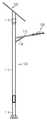
도 1은 본 발명의 예시적 실시예에 따른 태양광 라이팅 시스템의 개략적 구성도이다.
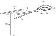
도 2는 본 발명의 다른 예시적 실시예에 따른 태양광 라이팅 시스템의 주요부의 구성도이다.
도 3은 본 발명의 일 실시예에 따른 태양광 라이팅 시스템에 사용되는 라이팅 헤드의 개략적인 단면도이다.
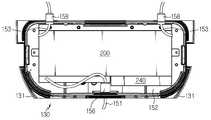
도 4는 일 실시예에 따른 태양광 라이팅 시스템에 사용되는 라이팅 헤드의 밀봉 수납부를 발췌 도시한 부분 사시도이다.
도 5는 본 발명의 일 실시예에 따른 태양광 라이팅 시스템에 사용되는 라이팅 헤드의 수직 단면 구성도이다.
도 6은 본 발명의 일 실시예에 따른 태양광 라이팅 시스템에 사용되는 라이팅 헤드의 수평 단면 구성도이다.
도 7은 본 발명의 일 실시예에 따른 태양광 라이팅 시스템에 이용될 수 있는 이차 전지의 개략적 투시 사시도이다.
도 8은 도 7의 우측면도이다.
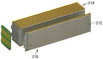
도 9는 본 발명의 일 실시예에 따른 태양광 라이팅 시스템에 이용될 수 있는 이차 전지의 주요부의 분리 사시도이다.
도 10은 본 발명의 일 실시예에 따른 태양광 라이팅 시스템에 이용될 수 있는 이차 전지의 셀 조립체의 분리 사시도이다.
도 11은 본 발명의 다른 실시예에 따른 태양광 라이팅 시스템에 이용될 수 있는 라이팅 헤드의 주요부를 도시하는 실물 사진이다.
도 12는 헤드 본체에 대해 헤드 커버가 개방된 상태의 도 11의 전체 사진이다.The detailed description of preferred embodiments of the invention as well as the summary of the invention described above will be better understood when read in conjunction with the accompanying drawings. For the purpose of describing a secondary battery for a solar lighting system and a solar lighting system using the same according to a preferred exemplary embodiment of the present disclosure, drawings of the preferred embodiments are shown. However, it should be understood that the present disclosure is not limited to the precise devices and instrumentalities shown in such drawings.
1 is a schematic configuration diagram of a solar lighting system according to an exemplary embodiment of the present invention.
Fig. 2 is a block diagram of a main part of a solar lighting system according to another exemplary embodiment of the present invention.
3 is a schematic cross-sectional view of a lighting head used in a solar lighting system according to an embodiment of the present invention.
Figure 4 is a partial perspective view showing an extract of the sealing head of the lighting head used in the solar lighting system according to an embodiment.
5 is a vertical cross-sectional configuration diagram of a lighting head used in a solar lighting system according to an embodiment of the present invention.
6 is a horizontal cross-sectional configuration diagram of a lighting head used in a solar lighting system according to an embodiment of the present invention.
7 is a schematic perspective perspective view of a secondary battery that can be used in a solar lighting system according to an embodiment of the present invention.
8 is a right side view of FIG. 7.
9 is an exploded perspective view of a main part of a secondary battery that can be used in a solar lighting system according to an embodiment of the present invention.
10 is an exploded perspective view of a cell assembly of a secondary battery that can be used in a solar lighting system according to an embodiment of the present invention.
11 is a real photograph showing a main part of a lighting head that can be used in a solar lighting system according to another embodiment of the present invention.
FIG. 12 is an overall photograph of FIG. 11 with the head cover open with respect to the head body.
이어지는 상세한 설명에서 사용된 특정의 용어는 편의를 위한 것이지 본 발명의 범위를 제한하는 것은 아니다. "우", "좌", "상면" 및 "하면"의 용어들은 참조가 이루어진 도면들에서의 방향을 나타낸다. "내측으로" 및 "외측으로"의 용어들은 각각 지정된 장치, 시스템 및 그 부재들의 기하학적 중심을 향하거나 그로부터 멀어지는 방향을 나타낸다. "전방", "후방", "상방", "하방" 및 그 관련 용어들 및 어구들은 참조가 이루어진 도면에서의 위치들 및 방위들을 나타내며 제한적이어서는 아니 된다. 이러한 용어들은 위에서 열거된 단어들, 그 파생어 및 유사한 의미의 단어들을 포함하는 개념이다.Certain terms used in the following detailed description are for convenience only and do not limit the scope of the invention. The terms "right", "left", "top" and "bottom" refer to the directions in the drawings to which reference is made. The terms "inwardly" and "outwardly" refer to the direction toward or away from the geometric center of the designated device, system and its members, respectively. “Forward”, “rear”, “upward”, “downward” and related terms and phrases refer to positions and orientations in the referenced drawings and should not be limiting. These terms are concepts including the words listed above, their derivatives, and words of similar meaning.
도 1은 본 발명의 일 실시예에 따른 따른 태양광 라이팅 시스템의 개략적 구성도이고, 도 2는 본 발명의 다른 예시적 실시예에 따른 태양광 라이팅 시스템의 주요부의 구성도이다.1 is a schematic configuration diagram of a solar lighting system according to an embodiment of the present invention, and FIG. 2 is a configuration diagram of a main part of a solar lighting system according to another exemplary embodiment of the present invention.
도 1 및 도 2를 참조하면, 태양광 라이팅 시스템(100)은 예를 들어, 가로등 또는 보안등과 같이 도로의 사이드에서 소정 높이 설치되어 운용될 수 있다. 태양광 라이팅 시스템(100)은 도로의 사이드에 설치될 수 있는 폴(110), 폴(110)에 설치되는 태양광 패널(120), 폴(110)로부터 연장하는 아암(112)에 설치되고 내부에 이차 전지(200: 도 3 참조)가 밀봉 수납되고 발광부(132)를 구비하는 라이팅 헤드(130), 및 이차 전지(200) 및/또는 발광부(132) 및/또는 태양광 패널(120)의 작동을 제어할 수 있도록 구성된 컨트롤러(140: 도 3 참조)를 구비한다.1 and 2, the
폴(110)은 지중에 매설될 수 있는 베이스부(114), 베이스부(114)와 대향되도록 마련된 패널 설치부(116), 패널 설치부(116) 또는 그로부터 소정 간격 이격된 지점으로부터 연장하고 라이팅 헤드(130)가 설치될 수 있는 아암(112)을 구비한다. 폴(110)은 예를 들어, 스테인레스 스틸과 같은 강성 재료를 이용하여 제조되고, 소정 간격을 가진 다수의 단위 폴들을 용접 또는 볼팅 공정을 통해 연결해서 사용할 수도 있다.The
도 2에 도시된 바와 같이, 태양광 패널(120)은 폴(110)의 패널 설치부(116)의 끝단에 설치된다. 패널 설치부(116)와 태양광 패널(120)은 패널 설치부(116)에 대해 태양광 패널(120)이 회전 및/또는 회동 가능하도록 별도의 커플링 구조를 각각 구비할 수 있다. 또한, 폴(110)의 아암(112)은 라이팅 헤드(130)를 지지하는 메인 아암(112)과 메인 아암(112)을 지지하는 지지 아암(118)으로 구분될 수 있다. 물론, 라이팅 헤드(130)는 하나의 아암의 끝단에 설치될 수도 있다. 변형된 실시예에 따르면, 라이팅 헤드(130)는 아암(112)의 끝단에 회전 및/또는 회동 가능하게 설치될 수도 있고, 유지 및 보수를 위해 라이팅 헤드(130)는 아암(112)으로부터 분리될 수 있게 구성될 수 있다.2, the
태양광 패널(120)은 주간에 태양을 이용하여 전력을 생산할 수 있게 구성되고, 현재 유통되고 있는 통상적인 태양 전지 모듈 또는 플렉스블 태양 전지 모듈로 제조될 수 있다. 전술한 바와 같이, 태양광 패널(120)의 일면에는 태양 전지들이 배치되고 타면에는 폴(110)의 패널 설치부(116)에 회동 또는 회전 가능하고, 선택적으로 패널 설치부(116)로부터 분리되게 고정될 수 있는 핏팅부(122)를 구비한다.The
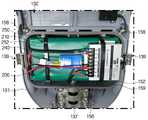
도 3은 본 발명의 일 실시예에 따른 태양광 라이팅 시스템에 사용되는 라이팅 헤드의 개략적인 단면도이고, 도 4는 일 실시예에 따른 태양광 라이팅 시스템에 사용되는 라이팅 헤드의 밀봉 수납부를 발췌 도시한 부분 사시도이고, 도 5는 본 발명의 일 실시예에 따른 태양광 라이팅 시스템에 사용되는 라이팅 헤드의 수직 단면 구성도이고, 도 6은 본 발명의 일 실시예에 따른 태양광 라이팅 시스템에 사용되는 라이팅 헤드의 수평 단면 구성도이다.3 is a schematic cross-sectional view of a lighting head used in a solar lighting system according to an embodiment of the present invention, and FIG. 4 is an excerpt showing a sealing housing of a lighting head used in a solar lighting system according to an embodiment Partial perspective view, Figure 5 is a vertical cross-sectional configuration diagram of a lighting head used in a solar lighting system according to an embodiment of the present invention, Figure 6 is a lighting used in a solar lighting system according to an embodiment of the present invention It is a horizontal cross-sectional configuration of the head.
도 3 내지 도 6을 참조하면, 라이팅 헤드(130)는 전술한 바와 같이, 발광부(132)를 통해 야간에 주변을 조명할 수 있도록 폴(110)의 아암(112)의 선단에 연결될 수 있는 연결부(134), 이차 전지(200)와 컨트롤러(140)가 밀봉 수납될 수 있는 밀봉 수납부(136), 및 발광부(132)가 설치될 수 있는 LED 모듈부(138)를 구비한다. 또한, 라이팅 헤드(130)는 헤드 본체(131) 및 예를 들어, 힌지(133)에 의해 헤드 본체(131)에 힌지 결합될 수 있도록 구성된 헤드 커버(135)를 포함한다.3 to 6, the
밀봉 수납부(136)는 후술하는 바와 같이, 헤드 본체(131)와 헤드 커버(135)가 공통적으로 형성하고, 연결부(134)와 LED 모듈부(138)는 헤드 본체(131)에 마련된다. LED 모듈부(138)에 대응되는 헤드 커버(135)에는 다수의 구멍들(135a)이 형성되어 있다. 연결부(131)는 태양광 패널(120)에 전기적으로 연결될 수 있는 제1 케이블(151: 도 6 참조)이 관통할 수 있는 구멍이 형성되어 있고, 아암(112)의 끝단에 선택적으로 결합 해제될 수 있는 연결 메커니즘(137)을 구비한다.As described later, the sealing
라이팅 헤드(130)는 예를 들어, 금속, FRP 등과 같은 강성 재질로 형성된다. 라이팅 헤드(130)는 헤드 본체(131)에 대해 헤드 커버(135)를 선택적으로 개방 또는 폐쇄하기 위한 클램핑 디바이스(139)를 구비한다. 클램핑 디바이스(139)는 예를 들어, 헤드 본체(131)에 설치된 후크와 그러한 후크가 선택적으로 체결될 수 있도록 헤드 커버(135)에 마련된 후크 홈을 포함한다.The
라이팅 헤드(130)의 밀봉 수납부(136)는, 이차 전지(200)가 수납될 수 있도록 헤드 본체(131)에 형성된 제1 수납부(152), 컨트롤러(140)가 수납될 수 있도록 헤드 커버(135)에 형성된 제2 수납부(154), 및 제1 수납부(152)와 제2 수납부(154)의 적어도 하나의 개방단에 마련 밀봉 부재(159)를 구비한다. 밀봉 부재(159)는 예를 들어, 실리콘, 고무 등과 같이 신축성과 밀봉성을 가진 소재로 제작된다.The sealing
구체적으로, 태양광 라이팅 시스템(100)이 조립됨으로써, 헤드 본체(131)에 대해 헤드 커버(135)가 밀폐될 때, 제1 수납부(152)와 제2 수납부(154)는 밀봉 부재(159)를 통해 내부에 수납된 이차 전지(200)와 컨트롤러(140)를 밀봉 수납할 수 있고, 라이팅 헤드(130)의 유지 또는 보수를 위해 헤드 본체(131)로부터 헤드 커버(135)를 개방할 때 제1 수납부(152)에 대해 제2 수납부(154)가 개방될 수 있는 구조를 가진다. 또한, 라이팅 헤드(130)가 필요에 의해 개방될 경우, 밀봉 수납부(136) 내부의 이차 전지(200)는 제1 수납부(152)에 고정될 수 있고 컨트롤러(140)는 제2 수납부(154)에 고정될 수 있도록 이차 전지(200)와 컨트롤러(140)는 밀봉 수납부(136) 내부에 수납될 수 있다.Specifically, when the
변형된 실시예에서, 밀봉 수납부(136) 내부의 이차 전지(200)와 컨트롤러(140)는 서로 소정 간격 이격되도록 구성하거나 이차 전지(200)와 컨트롤러(140) 사이에 열절연 쉬트 또는 패드(미도시)가 추가적으로 개재될 수 있다.In a modified embodiment, the
도 4 및 도 6에 도시된 바와 같이, 제1 수납부(152)는 태양광 패널(120)에 연결될 수 있는 제1 케이블(151)이 밀봉 관통할 수 있는 제1 관통구(156), 및 발광부(132)에 연결될 수 있는 적어도 하나의 제2 케이블(153)이 밀봉 관통할 수 있는 제2 관통구(158)를 구비한다.4 and 6, the
상기 발광부(132)는 효율이 높고, 전력 소비가 낮은 다수의 발광다이오드(LED)들이 집합된 적어도 하나 이상의 모듈 구조를 가짐으로써, LED 모듈의 유지 및 보수를 간단하게 할 수 있다.The
상기 컨트롤러(140)는 태양광 패널(120)로부터 생산되는 전기의 전압, 전류 및 기타 기능들을 제어하고 그러한 전력이 이차 전지(200)로 안정되게 공급될 수 있도록 제어하고, 발광부(132)의 LED 모듈들의 전압, 전류 및 기타 기능들을 제어할 수 있음은 물론, 이차 전지(200)의 PCM 또는 BMS와 별도로 모듈 형태의 이차 전지(200)의 충/방전 전류 및 전압을 제어할 수 있도록 구성된다.The
도 2를 참조하면, 본 발명의 다른 실시예에 따른 태양광 라이팅 시스템(100)은, 발광부(132)와 반대되는 라이팅 헤드(130)의 표면을 차양할 수 있도록 라이팅 헤드(130)로부터 미리결정된 간격만큼 이격되도록 아암(112) 또는 라이팅 헤드(130)에 설치되는 차양 플레이트(160)를 더 구비한다.Referring to Figure 2, the
차양 플레이트(160)는 주간에 라이팅 헤드(130)가 태양으로부터 직사광선에 의해 발생될 수 있는 열에 의해 라이팅 헤드(130)의 온도가 상승하는 것을 방지하기 위한 것이다. 일 실시예에서, 차양 플레이트(160)가 아암(112)에 설치되는 경우, 차양 플레이트(160)의 끝단에는 헤드 커버(135)가 헤드 본체(131)로부터 회동될 경우 동일한 방식으로 회동될 수 있는 회동 메커니즘을 구비할 수 있다. 다른 실시예에서, 차양 플레이트(160)는 라이팅 헤드(130)의 헤드 커버(135)의 표면과 소정 간격 이격되도록 그 테두리에서 연장되고 헤드 커버(135)에 탄성 결합될 수 있는 다수의 탄성 결합 돌기들(미도시)을 구비할 수 있다.The
도 7은 본 발명의 일 실시예에 따른 태양광 라이팅 시스템에 이용될 수 있는 이차 전지의 개략적 투시 사시도이고, 도 8은 도 7의 우측면도이고, 도 9는 본 발명의 일 실시예에 따른 태양광 라이팅 시스템에 이용될 수 있는 이차 전지의 주요부의 분리 사시도이고, 도 10은 본 발명의 일 실시예에 따른 태양광 라이팅 시스템에 이용될 수 있는 이차 전지의 셀 조립체의 분리 사시도이다.7 is a schematic perspective perspective view of a secondary battery that can be used in a solar lighting system according to an embodiment of the present invention, FIG. 8 is a right side view of FIG. 7, and FIG. 9 is a sun according to an embodiment of the present invention An exploded perspective view of a main part of a secondary battery that can be used in an optical lighting system, and FIG. 10 is an exploded perspective view of a cell assembly of a secondary battery that can be used in a solar lighting system according to an embodiment of the present invention.
도 7 내지 도 10을 참조하면, 이차 전지(200)는, 전기적으로 연결되고 서로 적층된 다수의 파우치형 셀들(212)이 조립된 셀 조립체(214)를 바인딩할 수 있는 소프트 팩(210), 소프트 팩(210)이 수납될 수 있는 메인 박스(220) 및 셀 조립체(214)에 연결된 보호회로모듈(240)을 수납할 수 있고 메인 박스(220)의 외벽면에 분리 가능하게 결합되는 서브 박스(230)를 포함한다.Referring to FIGS. 7 to 10, the
도 7 및 도 10을 참조하면, 소프트 팩(210)은 예를 들어, 235(길이)*120(폭)*120(높이)의 사이즈, 0.53kWh의 에너지, 36Ah의 정격 용량, 14.8DVC의 공칭 전압, 대략 2.3~3kg의 무게를 가지도록 파우치형 리튬 이차 전지용 베어 셀들(212)이 예를 들어, 3P4S 방식으로 전기적으로 연결된 셀 조립체(214)를 예를 들어, 절연 테이프 등을 이용하여 물리적으로 바인딩함으로써 구성될 수 있다. 여기서, 베어 셀들은 다수의 양극판과 다수의 음극판이 세퍼레이터의 양측에 소정 간격 배열된 전극 조립체가 전해질과 함께 파우치 내부에 밀봉된 구성이다. 도 10의 참조부호 216은 셀 조립체(214)의 전극 단자들을 연결하기 위한 충/방전 회로이다.7 and 10, the
메인 박스(220)는 소프트 팩(210)을 수납할 수 있는 수납부와 개방단을 구비하는 실질적으로 직육면체 형상의 메인 본체(222), 및 예를 들어, 볼트/너트(226) 등에 의해 메인 본체(222)의 개방단에 선택적으로 결합될 수 있는 메인 커버(224)를 구비한다.The
메인 본체(222)는 장변의 2개의 테두리들로부터 실질적으로 수직 방향 외측으로 각각 연장되는 2개의 메인 본체 결합부들(228)을 구비한다. 메인 커버(224)는 메인 본체 결합부(228)가 접촉되어 결합될 수 있는 메인 커버 결합부(221), 및 메인 커버 결합부(221)로부터 연장되어 형성되는 메인 박스 설치부(223)를 구비한다.The
메인 박스 설치부(223)는 메인 커버(224)의 적어도 하나의 모서리로부터 미리결정된 간격만큼 메인 커버(224)로부터 연장되는 이격 플랜지(225) 및 이격 플랜지(225)로부터 실질적으로 수직되게 외측으로 연장되고 태양광 라이팅 시스템의 헤드 본체(131)에 접촉될 수 있도록 설치 구멍(227a)이 관통 형성된 받침 플랜지(227)를 구비한다. 2개의 메인 본체 결합부들(228) 각각은 상응하는 테두리로부터 연장하는 길이가 서로 상이하다. 즉, 서브 박스(230)는 2개의 메인 본체 결합부들(228) 중 연장 길이가 긴 부분의 메인 박스(220)의 측면(도 7의 정면)에 설치된다. 서브 박스(230)는 보호회로모듈(240)을 관통하여 메인 박스(220) 표면에 고정될 수 있는 적어도 하나의 고정 부재(232)를 구비한다.The main
메인 박스(220)와 서브 박스(230)는 예를 들어, 알루미늄과 같은 강성 재료를 이용하여 절곡 가공 또는 사출 성형의 방법으로 제조되는 것이 바람직하다.The
도 11은 본 발명의 다른 실시예에 따른 태양광 라이팅 시스템에 이용될 수 있는 라이팅 헤드의 주요부를 도시하는 실물 사진이고, 도 12는 헤드 본체에 대해 헤드 커버가 개방된 상태의 도 11의 전체 사진이다.11 is a real photograph showing a main part of a lighting head that can be used in a solar lighting system according to another embodiment of the present invention, and FIG. 12 is a full photograph of FIG. 11 with the head cover open relative to the head body to be.
도 11 및 도 12를 참조하면, 본 실시예에 따른 이차 전지(200)는 태양광 패널(120)로부터 생산되는 전력을 저장할 수 있도록 구성된 것으로서, 전기적으로 연결되고 서로 적층된 다수의 파우치형 셀들(212)이 조립된 셀 조립체(214)를 바인딩할 수 있는 소프트 팩(210), 셀 조립체(214)에 전기적으로 연결된 보호회로모듈(240), 및 소프트 팩(210)을 밀봉 수납부(136)에 부착시키기 위한 부착 부재(250)를 포함한다. 부착 부재(250)는 소프트 팩(210)을 감싸는 2개의 밴드들(252) 및 밴드들(252)과 밀봉 수납부(136) 사이에 개재되도록 구성된 접착 테이프(미도시)를 구비한다.11 and 12, the
도 11 및 도 12의 실시예에 따르면, 이차 전지(200)는 전술한 실시예의 메인 박스(220)와 서버 박스(230)를 사용하지 않고, 소프트 팩(210)을 부착 부재(250)를 이용하여 밀봉 수납부(136)에 고정한 상태로 이용될 수 있는 경우의 예이다.11 and 12, the
전술한 상세한 설명 및 도면들은 본 발명의 바람직한 실시예들을 나타내는 한편, 첨부된 청구범위에서 정의된 바와 같이 본 발명의 기술적 사상 및 권리 범위를 벗어나지 않는 한 다양한 부가물, 변형물, 조합들 및/또는 대체물들이 만들어 질 수 있음을 이해해야 한다. 특히, 본 발명은 다른 요소들, 물질들, 성분들을 이용하여 본 발명의 사상 또는 필수적 특징들로부터 벗어나지 않는 범위 내에서 다른 특정한 형태, 구조, 배열, 비율들로 구현될 수 있음을 당업자는 이해할 것이다. 본 발명의 원칙을 벗어나지 않는 한 특정의 환경 및 작동 조건들에 특히 적합하도록 개조된 구조, 배열, 비율, 물질, 성분의 많은 변형과 함께 본 발명이 사용될 수 있음을 당업자는 이해할 것이다. 또한, 본 명세서에서 설명된 특징들은 단독적으로 사용될 수도 있고 다른 특징들과 조합하여 사용될 수도 있다. 예를 들어, 하나의 실시예와 관련하여 설명된 특징들은 다른 실시예에서 설명된 특징들과 함께 및/또는 상호 교체되어 사용될 수 있다. 따라서, 현재 개시된 실시예들은 모든 면에서 제한적이 아닌 예시적이고 설명적인 것으로 간주되어야 하며, 발명의 권리범위는 첨부된 청구범위에 의해 표시되며, 전술한 상세한 설명에 한정되어서는 아니된다.While the foregoing detailed description and drawings represent preferred embodiments of the present invention, various appendices, modifications, combinations and / or various modifications and / or combinations are provided without departing from the spirit and scope of the present invention as defined in the appended claims. It should be understood that alternatives can be made. In particular, those skilled in the art will understand that the present invention may be implemented in other specific shapes, structures, arrangements, and proportions without departing from the spirit or essential features of the present invention using other elements, materials, and components. . Those skilled in the art will understand that the present invention can be used with many modifications of structures, arrangements, proportions, materials, and components that have been adapted to be particularly suitable for specific environmental and operating conditions without departing from the principles of the invention. In addition, the features described herein may be used alone or in combination with other features. For example, features described in connection with one embodiment may be used in conjunction with and / or interchangeably with features described in another embodiment. Accordingly, the presently disclosed embodiments are to be regarded as illustrative and explanatory, not limiting in all respects, and the scope of the invention is indicated by the appended claims and should not be limited to the foregoing detailed description.
첨부된 청구범위의 넓은 범위를 벗어나지 않는 한 본 발명의 다양한 변형들 및 변경들이 가능함을 당업자는 이해할 것이다. 이러한 것들의 일부는 예시적으로 위에서 논의되었으며 다른 일부들은 당업자에게 명백할 것이다.Those skilled in the art will appreciate that various modifications and variations of the present invention are possible without departing from the broad scope of the appended claims. Some of these have been discussed above by way of example and others will be apparent to those skilled in the art.
100...태양광 라이팅 시스템 110...폴
112...아암 120...태양광 패널
130...라이팅 헤드 131...헤드 본체
132...발광부 134...연결부
135...헤드 커버 136...밀봉 수납부
140...컨트롤러 160...차양 플레이트
200...이차 전지 210...소프트 팩
212...파우치형 셀 214...셀 조립체
220...메인 박스 230...서브 박스
222...메인 본체 224...메인 커버
240...보호회로모듈 250...부착 부재
252...밴드100 ...
112 ...
130 ...
132 ... light emitting
135 ...
140 ...
200 ...
212 ...
220 ...
222 ...
240 ...
252 ... band
Claims (19)
Translated fromKorean상기 소프트 팩이 수납될 수 있는 메인 박스; 및
상기 셀 조립체에 연결된 보호회로모듈을 수납할 수 있고 상기 메인 박스의 외벽면에 분리 가능하게 결합되는 서브 박스를 포함하는, 태양광 라이팅 시스템용 이차 전지.
A soft pack capable of binding a cell assembly in which a plurality of pouch-shaped cells electrically connected and stacked with each other are assembled;
A main box in which the soft pack can be stored; And
A secondary battery for a solar lighting system, comprising a sub box that can receive a protective circuit module connected to the cell assembly and is detachably coupled to an outer wall surface of the main box.
상기 메인 박스는:
상기 소프트 팩을 수납할 수 있는 수납부와 개방단을 구비하는 실질적으로 직육면체 형상의 메인 본체; 및
상기 메인 본체의 개방단에 결합될 수 있는 메인 커버를 구비하는, 태양광 라이팅 시스템용 이차 전지.
In claim 1,
The main box is:
A substantially rectangular parallelepiped main body having a storage portion and an open end capable of storing the soft pack; And
A secondary battery for a solar lighting system having a main cover that can be coupled to an open end of the main body.
상기 메인 본체는 장변의 2개의 테두리들로부터 실질적으로 수직 방향 외측으로 각각 연장되는 2개의 메인 본체 결합부들을 구비하고;
상기 메인 커버는 상기 메인 본체 결합부가 접촉되어 결합될 수 있는 메인 커버 결합부, 및 상기 메인 커버 결합부로부터 연장되어 형성되는 메인 박스 설치부를 구비하는, 태양광 라이팅 시스템용 이차 전지.
In claim 2,
The main body has two main body engaging portions extending from the two rims of the long side outward in a substantially vertical direction, respectively;
The main cover includes a main cover coupling portion to which the main body coupling portion is contacted and coupled, and a main box installation portion extending from the main cover coupling portion to form a secondary battery for a solar lighting system.
상기 메인 박스 설치부는:
상기 메인 커버의 적어도 하나의 모서리로부터 미리결정된 간격만큼 상기 메인 커버로부터 연장되는 이격 플랜지; 및
상기 이격 플랜지로부터 실질적으로 수직되게 외측으로 연장되고 태양광 라이팅 시스템의 헤드 본체에 접촉될 수 있도록 설치 구멍이 관통 형성된 베이스 플랜지를 구비하는, 태양광 라이팅 시스템용 이차 전지.
In claim 3,
The main box installation unit:
A spacing flange extending from the main cover by a predetermined distance from at least one edge of the main cover; And
A secondary battery for a solar lighting system, comprising a base flange extending substantially vertically outwardly from the spacing flange and having a through hole formed therethrough to allow contact with the head body of the solar lighting system.
상기 2개의 메인 본체 결합부들 각각은 상응하는 상기 테두리로부터 연장하는 길이가 서로 상이한, 태양광 라이팅 시스템용 이차 전지.
In claim 3,
Each of the two main body coupling portions has a different length extending from the corresponding rim, a secondary battery for a solar lighting system.
상기 서브 박스는 상기 2개의 메인 본체 결합부들 중 연장 길이가 긴 부분의 메인 박스의 측면에 설치되는, 태양광 라이팅 시스템용 이차 전지.
In claim 5,
The sub box is a secondary battery for a solar lighting system, which is installed on the side of the main box of the long extension portion of the two main body coupling portion.
상기 서브 박스는, 상기 보호회로모듈을 관통하여 상기 메인 박스 표면에 고정될 수 있는 적어도 하나의 고정 부재를 더 구비하는, 태양광 라이팅 시스템용 이차 전지.
In claim 1,
The sub box further comprises at least one fixing member that can be fixed to the surface of the main box through the protection circuit module, a secondary battery for a solar lighting system.
상기 태양광 패널로부터 생산되는 전력을 저장할 수 있는 이차 전지가 밀봉 수납될 수 있는 밀봉 수납부, 및 상기 이차 전지로부터 선택적으로 전력을 공급받아 발광될 수 있는 발광부를 구비하는 라이팅 헤드; 및
상기 이차 전지 및/또는 상기 발광부 및/또는 상기 태양광 패널의 작동을 제어할 수 있도록 구성된 컨트롤러를 구비하는, 태양광 라이팅 시스템.
Solar panels;
A lighting head having a sealed storage unit in which a secondary battery capable of storing electric power produced from the solar panel can be sealed and stored, and a light emitting unit capable of selectively receiving power from the secondary battery and emitting light; And
And a controller configured to control the operation of the secondary battery and / or the light emitting unit and / or the solar panel.
상기 컨트롤러는 상기 이차 전지와 함께 상기 밀봉 수납부에 수납될 수 있는, 태양광 라이팅 시스템.
In claim 8,
The controller can be accommodated in the sealed storage unit with the secondary battery, a solar lighting system.
상기 라이팅 헤드는 헤드 본체와 헤드 커버를 포함하고;
상기 밀봉 수납부는, 상기 이차 전지가 수납될 수 있도록 상기 헤드 본체에 형성된 제1 수납부, 상기 컨트롤러가 수납될 수 있도록 상기 헤드 커버에 형성된 제2 수납부, 및 상기 제1 수납부와 상기 제2 수납부의 적어도 하나의 개방단에 마련 밀봉부재를 구비하는, 태양광 라이팅 시스템.
In claim 8,
The lighting head includes a head body and a head cover;
The sealed storage unit includes a first storage unit formed in the head body so that the secondary battery can be stored, a second storage unit formed in the head cover so that the controller can be stored, and the first storage unit and the second storage unit. A solar lighting system comprising a sealing member provided on at least one open end of the storage unit.
상기 제1 수납부는:
상기 태양광 패널에 연결될 수 있는 케이블이 밀봉 관통할 수 있는 제1 관통구; 및
상기 발광부에 연결될 수 있는 적어도 하나의 케이블이 밀봉 관통할 수 있는 제2 관통구를 구비하는, 태양광 라이팅 시스템.
In claim 10,
The first storage unit:
A first through hole through which a cable that can be connected to the solar panel is sealed; And
A solar lighting system having a second through hole through which at least one cable that can be connected to the light emitting portion is sealed.
상기 헤드 커버는 상기 헤드 본체에 대해 힌지 결합될 수 있는, 태양광 라이팅 시스템.
In claim 10,
The head cover can be hinged to the head body, a solar lighting system.
상기 헤드 본체에 대해 상기 헤드 커버를 선택적으로 개방 또는 폐쇄하기 위한 클램핑 디바이스를 더 구비하는, 태양광 라이팅 시스템.
In claim 10,
And a clamping device for selectively opening or closing the head cover relative to the head body.
상기 발광부는 발광다이오드(LED) 모듈을 구비하는, 태양광 라이팅 시스템.
In claim 8,
The light emitting unit is provided with a light emitting diode (LED) module, a solar lighting system.
상기 이차 전지는, 청구항 1 내지 청구항 9 중 어느 한 항의 이차 전지를 포함하는, 태양광 라이팅 시스템.
In claim 8,
The secondary battery comprises the secondary battery of any one of claims 1 to 9, a solar lighting system.
상기 이차 전지는:
전기적으로 연결되고 서로 적층된 다수의 파우치형 셀들이 조립된 셀 조립체를 바인딩할 수 있는 소프트 팩;
상기 셀 조립체에 전기적으로 연결된 보호회로모듈; 및
상기 소프트 팩을 상기 밀봉 수납부에 부착시키기 위한 부착 부재를 포함하는, 태양광 라이팅 시스템.
In claim 8,
The secondary battery is:
A soft pack capable of binding a cell assembly in which a plurality of pouch-shaped cells electrically connected and stacked with each other are assembled;
A protection circuit module electrically connected to the cell assembly; And
And an attachment member for attaching the soft pack to the sealed housing.
상기 부착 부재는:
상기 소프트 팩을 감싸는 적어도 하나의 밴드; 및
상기 밴드와 상기 밀봉 수납부 사이에 개재될 수 있는 접착테이프를 구비하는, 태양광 라이팅 시스템.
In claim 16,
The attachment member is:
At least one band surrounding the soft pack; And
A solar lighting system comprising an adhesive tape that can be interposed between the band and the sealed housing.
상기 태양광 패널은 지면에 고정된 가로등 또는 보안등의 폴(pole)에 설치되고;
상기 라이팅 헤드는 상기 등주로부터 연장되는 아암(arm)에 설치되는, 태양광 라이팅 시스템.In claim 8,
The solar panel is installed on a pole of a street light or security light fixed to the ground;
The lighting head is installed on an arm extending from the column, a solar lighting system.
상기 발광부와 반대되는 상기 라이팅 헤드의 표면을 차양할 수 있도록 상기 라이팅 헤드와 미리결정된 간격으로 이격되도록 상기 아암에 설치되는 차양 플레이트를 더 구비하는, 태양광 라이팅 시스템.In claim 18,
A solar lighting system further comprising an awning plate installed on the arm so as to be spaced apart at a predetermined distance from the lighting head so as to shade the surface of the lighting head opposite to the light emitting unit.
Priority Applications (1)
| Application Number | Priority Date | Filing Date | Title |
|---|---|---|---|
| KR1020180128330AKR102157888B1 (en) | 2018-10-25 | 2018-10-25 | Secondary battery for solar lighting system and solar lighting system utilizing the same |
Applications Claiming Priority (1)
| Application Number | Priority Date | Filing Date | Title |
|---|---|---|---|
| KR1020180128330AKR102157888B1 (en) | 2018-10-25 | 2018-10-25 | Secondary battery for solar lighting system and solar lighting system utilizing the same |
Publications (2)
| Publication Number | Publication Date |
|---|---|
| KR20200046754Atrue KR20200046754A (en) | 2020-05-07 |
| KR102157888B1 KR102157888B1 (en) | 2020-09-18 |
Family
ID=70734295
Family Applications (1)
| Application Number | Title | Priority Date | Filing Date |
|---|---|---|---|
| KR1020180128330AActiveKR102157888B1 (en) | 2018-10-25 | 2018-10-25 | Secondary battery for solar lighting system and solar lighting system utilizing the same |
Country Status (1)
| Country | Link |
|---|---|
| KR (1) | KR102157888B1 (en) |
Cited By (1)
| Publication number | Priority date | Publication date | Assignee | Title |
|---|---|---|---|---|
| KR20220077760A (en)* | 2020-12-02 | 2022-06-09 | (주)엘씨엠싸이언스 | Thermal spreader-type lighting device for solar lighting system and solar lighting system utilizing the same |
Citations (3)
| Publication number | Priority date | Publication date | Assignee | Title |
|---|---|---|---|---|
| KR20170021130A (en)* | 2015-08-17 | 2017-02-27 | 삼성에스디아이 주식회사 | Battery module having holder |
| KR20170114340A (en)* | 2016-04-04 | 2017-10-16 | 주식회사 스카이 쏠라 | Photovoltaic device formed in a cross shape |
| KR20180047791A (en)* | 2016-11-01 | 2018-05-10 | 현대모비스 주식회사 | integrated high voltage junction unit for electric vehicle |
- 2018
- 2018-10-25KRKR1020180128330Apatent/KR102157888B1/enactiveActive
Patent Citations (3)
| Publication number | Priority date | Publication date | Assignee | Title |
|---|---|---|---|---|
| KR20170021130A (en)* | 2015-08-17 | 2017-02-27 | 삼성에스디아이 주식회사 | Battery module having holder |
| KR20170114340A (en)* | 2016-04-04 | 2017-10-16 | 주식회사 스카이 쏠라 | Photovoltaic device formed in a cross shape |
| KR20180047791A (en)* | 2016-11-01 | 2018-05-10 | 현대모비스 주식회사 | integrated high voltage junction unit for electric vehicle |
Cited By (1)
| Publication number | Priority date | Publication date | Assignee | Title |
|---|---|---|---|---|
| KR20220077760A (en)* | 2020-12-02 | 2022-06-09 | (주)엘씨엠싸이언스 | Thermal spreader-type lighting device for solar lighting system and solar lighting system utilizing the same |
Also Published As
| Publication number | Publication date |
|---|---|
| KR102157888B1 (en) | 2020-09-18 |
Similar Documents
| Publication | Publication Date | Title |
|---|---|---|
| JP5241745B2 (en) | Solar cell power supply | |
| US20110181233A1 (en) | Solar cell power supply device and rechargeable battery solar charging method | |
| KR100900032B1 (en) | Battery built-in street light | |
| KR20120029837A (en) | Secondary battery package having peltier effect and electricity generation streetlamp by sun having of that | |
| CN207674302U (en) | A kind of solar street light | |
| CN105070227A (en) | Foldable warning triangular frame | |
| CN105070226A (en) | Foldable warning triangular frame | |
| KR102157888B1 (en) | Secondary battery for solar lighting system and solar lighting system utilizing the same | |
| KR100970158B1 (en) | Street light with charging terminal case | |
| US10349480B2 (en) | Hybrid green-energy street light apparatus | |
| CN218957967U (en) | Adapter and battery | |
| KR102495630B1 (en) | Thermal spreader-type lighting device for solar lighting system and solar lighting system utilizing the same | |
| CN211780716U (en) | Solar street lamp of lithium titanate battery based on automatic protection | |
| CN209384137U (en) | A voice warning device for road curves | |
| CN210771837U (en) | Integrated portable solar street lamp holder | |
| CN217653783U (en) | Integrated form solar street lamp convenient to installation | |
| CN218257791U (en) | A solar charging stake for new energy automobile charges | |
| CN218095695U (en) | On-duty warning lamp with multiple power supply mode | |
| CN202758576U (en) | Solar building number plate | |
| CN214847598U (en) | Solar LED advertising lamp | |
| KR101463686B1 (en) | Battery storage apparatus for street light using natural energy | |
| US20120061152A1 (en) | Method for generating electricity from solar panels for emergency and utility vehicles | |
| CN202651230U (en) | Battery box for solar photovoltaic system | |
| KR102373444B1 (en) | Pole system for solar lighting system | |
| CN214624325U (en) | Car roof LED lamp structure of joint formula |
Legal Events
| Date | Code | Title | Description |
|---|---|---|---|
| PA0109 | Patent application | St.27 status event code:A-0-1-A10-A12-nap-PA0109 | |
| PA0201 | Request for examination | St.27 status event code:A-1-2-D10-D11-exm-PA0201 | |
| T11-X000 | Administrative time limit extension requested | St.27 status event code:U-3-3-T10-T11-oth-X000 | |
| T11-X000 | Administrative time limit extension requested | St.27 status event code:U-3-3-T10-T11-oth-X000 | |
| T11-X000 | Administrative time limit extension requested | St.27 status event code:U-3-3-T10-T11-oth-X000 | |
| T11-X000 | Administrative time limit extension requested | St.27 status event code:U-3-3-T10-T11-oth-X000 | |
| P11-X000 | Amendment of application requested | St.27 status event code:A-2-2-P10-P11-nap-X000 | |
| P13-X000 | Application amended | St.27 status event code:A-2-2-P10-P13-nap-X000 | |
| D13-X000 | Search requested | St.27 status event code:A-1-2-D10-D13-srh-X000 | |
| D14-X000 | Search report completed | St.27 status event code:A-1-2-D10-D14-srh-X000 | |
| PE0902 | Notice of grounds for rejection | St.27 status event code:A-1-2-D10-D21-exm-PE0902 | |
| E13-X000 | Pre-grant limitation requested | St.27 status event code:A-2-3-E10-E13-lim-X000 | |
| P11-X000 | Amendment of application requested | St.27 status event code:A-2-2-P10-P11-nap-X000 | |
| P13-X000 | Application amended | St.27 status event code:A-2-2-P10-P13-nap-X000 | |
| E902 | Notification of reason for refusal | ||
| PE0902 | Notice of grounds for rejection | St.27 status event code:A-1-2-D10-D21-exm-PE0902 | |
| P11-X000 | Amendment of application requested | St.27 status event code:A-2-2-P10-P11-nap-X000 | |
| P13-X000 | Application amended | St.27 status event code:A-2-2-P10-P13-nap-X000 | |
| PG1501 | Laying open of application | St.27 status event code:A-1-1-Q10-Q12-nap-PG1501 | |
| E701 | Decision to grant or registration of patent right | ||
| PE0701 | Decision of registration | St.27 status event code:A-1-2-D10-D22-exm-PE0701 | |
| GRNT | Written decision to grant | ||
| PR0701 | Registration of establishment | St.27 status event code:A-2-4-F10-F11-exm-PR0701 | |
| PR1002 | Payment of registration fee | St.27 status event code:A-2-2-U10-U11-oth-PR1002 Fee payment year number:1 | |
| PG1601 | Publication of registration | St.27 status event code:A-4-4-Q10-Q13-nap-PG1601 | |
| P14-X000 | Amendment of ip right document requested | St.27 status event code:A-5-5-P10-P14-nap-X000 | |
| PN2301 | Change of applicant | St.27 status event code:A-5-5-R10-R11-asn-PN2301 | |
| P16-X000 | Ip right document amended | St.27 status event code:A-5-5-P10-P16-nap-X000 | |
| PN2301 | Change of applicant | St.27 status event code:A-5-5-R10-R14-asn-PN2301 | |
| P22-X000 | Classification modified | St.27 status event code:A-4-4-P10-P22-nap-X000 | |
| P22-X000 | Classification modified | St.27 status event code:A-4-4-P10-P22-nap-X000 | |
| S14-X000 | Exclusive voluntary license recorded | St.27 status event code:A-4-4-S10-S14-lic-X000 | |
| R18-X000 | Changes to party contact information recorded | St.27 status event code:A-5-5-R10-R18-oth-X000 | |
| P22-X000 | Classification modified | St.27 status event code:A-4-4-P10-P22-nap-X000 | |
| S16-X000 | Recordation of exclusive voluntary license cancelled | St.27 status event code:A-4-4-S10-S16-lic-X000 | |
| R18-X000 | Changes to party contact information recorded | St.27 status event code:A-5-5-R10-R18-oth-X000 | |
| S14-X000 | Exclusive voluntary license recorded | St.27 status event code:A-4-4-S10-S14-lic-X000 | |
| R18-X000 | Changes to party contact information recorded | St.27 status event code:A-5-5-R10-R18-oth-X000 | |
| PR1001 | Payment of annual fee | St.27 status event code:A-4-4-U10-U11-oth-PR1001 Fee payment year number:4 | |
| P14-X000 | Amendment of ip right document requested | St.27 status event code:A-5-5-P10-P14-nap-X000 | |
| PN2301 | Change of applicant | St.27 status event code:A-5-5-R10-R11-asn-PN2301 | |
| P16-X000 | Ip right document amended | St.27 status event code:A-5-5-P10-P16-nap-X000 | |
| PN2301 | Change of applicant | St.27 status event code:A-5-5-R10-R14-asn-PN2301 | |
| PR1001 | Payment of annual fee | St.27 status event code:A-4-4-U10-U11-oth-PR1001 Fee payment year number:5 | |
| PN2301 | Change of applicant | St.27 status event code:A-5-5-R10-R13-asn-PN2301 St.27 status event code:A-5-5-R10-R11-asn-PN2301 | |
| P14-X000 | Amendment of ip right document requested | St.27 status event code:A-5-5-P10-P14-nap-X000 | |
| PR1001 | Payment of annual fee | St.27 status event code:A-4-4-U10-U11-oth-PR1001 Fee payment year number:6 |