KR20200043540A - Particulate foam in coated carrier - Google Patents
Particulate foam in coated carrierDownload PDFInfo
- Publication number
- KR20200043540A KR20200043540AKR1020207011285AKR20207011285AKR20200043540AKR 20200043540 AKR20200043540 AKR 20200043540AKR 1020207011285 AKR1020207011285 AKR 1020207011285AKR 20207011285 AKR20207011285 AKR 20207011285AKR 20200043540 AKR20200043540 AKR 20200043540A
- Authority
- KR
- South Korea
- Prior art keywords
- case
- article
- elastomeric material
- sole
- particulate material
- Prior art date
- Legal status (The legal status is an assumption and is not a legal conclusion. Google has not performed a legal analysis and makes no representation as to the accuracy of the status listed.)
- Granted
Links
- 239000006260foamSubstances0.000titleclaimsdescription141
- 239000011236particulate materialSubstances0.000claimsabstractdescription223
- 239000013536elastomeric materialSubstances0.000claimsdescription238
- 239000000463materialSubstances0.000claimsdescription113
- 239000011324beadSubstances0.000claimsdescription58
- 239000007788liquidSubstances0.000claimsdescription44
- 239000011148porous materialSubstances0.000claimsdescription14
- 238000000034methodMethods0.000description52
- 210000002683footAnatomy0.000description47
- 210000004744fore-footAnatomy0.000description18
- 239000011248coating agentSubstances0.000description16
- 238000000576coating methodMethods0.000description16
- 210000000474heelAnatomy0.000description16
- 230000009471actionEffects0.000description14
- 238000000465mouldingMethods0.000description13
- 230000006835compressionEffects0.000description12
- 238000007906compressionMethods0.000description12
- 239000004744fabricSubstances0.000description11
- 230000008569processEffects0.000description11
- 238000004519manufacturing processMethods0.000description10
- 210000000452mid-footAnatomy0.000description10
- 239000012530fluidSubstances0.000description9
- 238000005192partitionMethods0.000description9
- 239000012528membraneSubstances0.000description8
- 229920000642polymerPolymers0.000description8
- 239000004677NylonSubstances0.000description6
- 239000006261foam materialSubstances0.000description6
- 238000007373indentationMethods0.000description6
- 229920001778nylonPolymers0.000description6
- 229920002635polyurethanePolymers0.000description6
- 239000004814polyurethaneSubstances0.000description6
- 239000000835fiberSubstances0.000description5
- 229920001971elastomerPolymers0.000description4
- 230000005012migrationEffects0.000description4
- 238000013508migrationMethods0.000description4
- 239000002861polymer materialSubstances0.000description4
- 239000000853adhesiveSubstances0.000description3
- 238000010586diagramMethods0.000description3
- 239000002245particleSubstances0.000description3
- 229920000728polyesterPolymers0.000description3
- 239000007921spraySubstances0.000description3
- RRHGJUQNOFWUDK-UHFFFAOYSA-NIsopreneChemical compoundCC(=C)C=CRRHGJUQNOFWUDK-UHFFFAOYSA-N0.000description2
- 239000004721Polyphenylene oxideSubstances0.000description2
- 238000005299abrasionMethods0.000description2
- 230000001070adhesive effectEffects0.000description2
- 210000003423ankleAnatomy0.000description2
- 230000004888barrier functionEffects0.000description2
- 230000015572biosynthetic processEffects0.000description2
- 230000003139buffering effectEffects0.000description2
- -1chlorosulfonylChemical group0.000description2
- 239000000806elastomerSubstances0.000description2
- 229920000570polyetherPolymers0.000description2
- 229920001021polysulfidePolymers0.000description2
- 239000005077polysulfideSubstances0.000description2
- 150000008117polysulfidesPolymers0.000description2
- 230000004044responseEffects0.000description2
- 230000004043responsivenessEffects0.000description2
- 239000005060rubberSubstances0.000description2
- 239000004215Carbon black (E152)Substances0.000description1
- 239000004709Chlorinated polyethyleneSubstances0.000description1
- 229920002943EPDM rubberPolymers0.000description1
- VGGSQFUCUMXWEO-UHFFFAOYSA-NEtheneChemical compoundC=CVGGSQFUCUMXWEO-UHFFFAOYSA-N0.000description1
- 239000005977EthyleneSubstances0.000description1
- IAYPIBMASNFSPL-UHFFFAOYSA-NEthylene oxideChemical compoundC1CO1IAYPIBMASNFSPL-UHFFFAOYSA-N0.000description1
- 244000043261Hevea brasiliensisSpecies0.000description1
- VHOQXEIFYTTXJU-UHFFFAOYSA-NIsobutylene-isoprene copolymerChemical compoundCC(C)=C.CC(=C)C=CVHOQXEIFYTTXJU-UHFFFAOYSA-N0.000description1
- 229920000459Nitrile rubberPolymers0.000description1
- 239000005062PolybutadieneSubstances0.000description1
- 239000004698PolyethyleneSubstances0.000description1
- 229920006311Urethane elastomerPolymers0.000description1
- 229920000800acrylic rubberPolymers0.000description1
- 210000000988bone and boneAnatomy0.000description1
- 210000000459calcaneusAnatomy0.000description1
- 230000008859changeEffects0.000description1
- YACLQRRMGMJLJV-UHFFFAOYSA-NchloropreneChemical compoundClC(=C)C=CYACLQRRMGMJLJV-UHFFFAOYSA-N0.000description1
- 229920001577copolymerPolymers0.000description1
- 238000009792diffusion processMethods0.000description1
- HQQADJVZYDDRJT-UHFFFAOYSA-Nethene;prop-1-eneChemical groupC=C.CC=CHQQADJVZYDDRJT-UHFFFAOYSA-N0.000description1
- BFMKFCLXZSUVPI-UHFFFAOYSA-Nethyl but-3-enoateChemical compoundCCOC(=O)CC=CBFMKFCLXZSUVPI-UHFFFAOYSA-N0.000description1
- 230000005484gravityEffects0.000description1
- 229930195733hydrocarbonNatural products0.000description1
- 150000002430hydrocarbonsChemical class0.000description1
- 229920002681hypalonPolymers0.000description1
- 238000003780insertionMethods0.000description1
- 230000037431insertionEffects0.000description1
- 239000010985leatherSubstances0.000description1
- 239000002649leather substituteSubstances0.000description1
- 210000001872metatarsal boneAnatomy0.000description1
- 238000012986modificationMethods0.000description1
- 230000004048modificationEffects0.000description1
- 229920003052natural elastomerPolymers0.000description1
- 229920001194natural rubberPolymers0.000description1
- 238000012856packingMethods0.000description1
- 230000000149penetrating effectEffects0.000description1
- 239000012466permeateSubstances0.000description1
- 229920001084poly(chloroprene)Polymers0.000description1
- 229920000058polyacrylatePolymers0.000description1
- 229920002857polybutadienePolymers0.000description1
- 229920000573polyethylenePolymers0.000description1
- 229920001296polysiloxanePolymers0.000description1
- 239000000047productSubstances0.000description1
- 238000011084recoveryMethods0.000description1
- 238000007789sealingMethods0.000description1
- 238000000926separation methodMethods0.000description1
- 229920001897terpolymerPolymers0.000description1
- 229920002803thermoplastic polyurethanePolymers0.000description1
- 210000003853toe phalangesAnatomy0.000description1
- 239000011800void materialSubstances0.000description1
Images


Classifications
- A—HUMAN NECESSITIES
- A43—FOOTWEAR
- A43B—CHARACTERISTIC FEATURES OF FOOTWEAR; PARTS OF FOOTWEAR
- A43B13/00—Soles; Sole-and-heel integral units
- A43B13/14—Soles; Sole-and-heel integral units characterised by the constructive form
- A43B13/18—Resilient soles
- A43B13/181—Resiliency achieved by the structure of the sole
- A—HUMAN NECESSITIES
- A43—FOOTWEAR
- A43B—CHARACTERISTIC FEATURES OF FOOTWEAR; PARTS OF FOOTWEAR
- A43B13/00—Soles; Sole-and-heel integral units
- A43B13/14—Soles; Sole-and-heel integral units characterised by the constructive form
- A43B13/141—Soles; Sole-and-heel integral units characterised by the constructive form with a part of the sole being flexible, e.g. permitting articulation or torsion
- A—HUMAN NECESSITIES
- A43—FOOTWEAR
- A43B—CHARACTERISTIC FEATURES OF FOOTWEAR; PARTS OF FOOTWEAR
- A43B1/00—Footwear characterised by the material
- A43B1/0072—Footwear characterised by the material made at least partially of transparent or translucent materials
- A—HUMAN NECESSITIES
- A43—FOOTWEAR
- A43B—CHARACTERISTIC FEATURES OF FOOTWEAR; PARTS OF FOOTWEAR
- A43B13/00—Soles; Sole-and-heel integral units
- A43B13/02—Soles; Sole-and-heel integral units characterised by the material
- A43B13/04—Plastics, rubber or vulcanised fibre
- A—HUMAN NECESSITIES
- A43—FOOTWEAR
- A43B—CHARACTERISTIC FEATURES OF FOOTWEAR; PARTS OF FOOTWEAR
- A43B13/00—Soles; Sole-and-heel integral units
- A43B13/02—Soles; Sole-and-heel integral units characterised by the material
- A43B13/12—Soles with several layers of different materials
- A43B13/122—Soles with several layers of different materials characterised by the outsole or external layer
- A—HUMAN NECESSITIES
- A43—FOOTWEAR
- A43B—CHARACTERISTIC FEATURES OF FOOTWEAR; PARTS OF FOOTWEAR
- A43B13/00—Soles; Sole-and-heel integral units
- A43B13/02—Soles; Sole-and-heel integral units characterised by the material
- A43B13/12—Soles with several layers of different materials
- A43B13/125—Soles with several layers of different materials characterised by the midsole or middle layer
- A43B13/127—Soles with several layers of different materials characterised by the midsole or middle layer the midsole being multilayer
- A—HUMAN NECESSITIES
- A43—FOOTWEAR
- A43B—CHARACTERISTIC FEATURES OF FOOTWEAR; PARTS OF FOOTWEAR
- A43B13/00—Soles; Sole-and-heel integral units
- A43B13/14—Soles; Sole-and-heel integral units characterised by the constructive form
- A43B13/16—Pieced soles
- A—HUMAN NECESSITIES
- A43—FOOTWEAR
- A43B—CHARACTERISTIC FEATURES OF FOOTWEAR; PARTS OF FOOTWEAR
- A43B13/00—Soles; Sole-and-heel integral units
- A43B13/14—Soles; Sole-and-heel integral units characterised by the constructive form
- A43B13/18—Resilient soles
- A43B13/181—Resiliency achieved by the structure of the sole
- A43B13/186—Differential cushioning region, e.g. cushioning located under the ball of the foot
- A—HUMAN NECESSITIES
- A43—FOOTWEAR
- A43B—CHARACTERISTIC FEATURES OF FOOTWEAR; PARTS OF FOOTWEAR
- A43B13/00—Soles; Sole-and-heel integral units
- A43B13/14—Soles; Sole-and-heel integral units characterised by the constructive form
- A43B13/18—Resilient soles
- A43B13/187—Resiliency achieved by the features of the material, e.g. foam, non liquid materials
- A43B13/188—Differential cushioning regions
- A—HUMAN NECESSITIES
- A43—FOOTWEAR
- A43B—CHARACTERISTIC FEATURES OF FOOTWEAR; PARTS OF FOOTWEAR
- A43B13/00—Soles; Sole-and-heel integral units
- A43B13/14—Soles; Sole-and-heel integral units characterised by the constructive form
- A43B13/18—Resilient soles
- A43B13/189—Resilient soles filled with a non-compressible fluid, e.g. gel, water
- A—HUMAN NECESSITIES
- A43—FOOTWEAR
- A43B—CHARACTERISTIC FEATURES OF FOOTWEAR; PARTS OF FOOTWEAR
- A43B13/00—Soles; Sole-and-heel integral units
- A43B13/14—Soles; Sole-and-heel integral units characterised by the constructive form
- A43B13/18—Resilient soles
- A43B13/20—Pneumatic soles filled with a compressible fluid, e.g. air, gas
- A43B13/206—Pneumatic soles filled with a compressible fluid, e.g. air, gas provided with tubes or pipes or tubular shaped cushioning members
- A—HUMAN NECESSITIES
- A43—FOOTWEAR
- A43B—CHARACTERISTIC FEATURES OF FOOTWEAR; PARTS OF FOOTWEAR
- A43B5/00—Footwear for sporting purposes
- A—HUMAN NECESSITIES
- A43—FOOTWEAR
- A43B—CHARACTERISTIC FEATURES OF FOOTWEAR; PARTS OF FOOTWEAR
- A43B7/00—Footwear with health or hygienic arrangements
- A43B7/14—Footwear with health or hygienic arrangements with foot-supporting parts
- A43B7/1405—Footwear with health or hygienic arrangements with foot-supporting parts with pads or holes on one or more locations, or having an anatomical or curved form
- A43B7/141—Footwear with health or hygienic arrangements with foot-supporting parts with pads or holes on one or more locations, or having an anatomical or curved form having an anatomical or curved form
- A—HUMAN NECESSITIES
- A43—FOOTWEAR
- A43B—CHARACTERISTIC FEATURES OF FOOTWEAR; PARTS OF FOOTWEAR
- A43B7/00—Footwear with health or hygienic arrangements
- A43B7/32—Footwear with health or hygienic arrangements with shock-absorbing means
- B—PERFORMING OPERATIONS; TRANSPORTING
- B32—LAYERED PRODUCTS
- B32B—LAYERED PRODUCTS, i.e. PRODUCTS BUILT-UP OF STRATA OF FLAT OR NON-FLAT, e.g. CELLULAR OR HONEYCOMB, FORM
- B32B25/00—Layered products comprising a layer of natural or synthetic rubber
- B32B25/04—Layered products comprising a layer of natural or synthetic rubber comprising rubber as the main or only constituent of a layer, which is next to another layer of the same or of a different material
- B32B25/047—Layered products comprising a layer of natural or synthetic rubber comprising rubber as the main or only constituent of a layer, which is next to another layer of the same or of a different material of particles
- B—PERFORMING OPERATIONS; TRANSPORTING
- B32—LAYERED PRODUCTS
- B32B—LAYERED PRODUCTS, i.e. PRODUCTS BUILT-UP OF STRATA OF FLAT OR NON-FLAT, e.g. CELLULAR OR HONEYCOMB, FORM
- B32B25/00—Layered products comprising a layer of natural or synthetic rubber
- B32B25/14—Layered products comprising a layer of natural or synthetic rubber comprising synthetic rubber copolymers
- B—PERFORMING OPERATIONS; TRANSPORTING
- B32—LAYERED PRODUCTS
- B32B—LAYERED PRODUCTS, i.e. PRODUCTS BUILT-UP OF STRATA OF FLAT OR NON-FLAT, e.g. CELLULAR OR HONEYCOMB, FORM
- B32B5/00—Layered products characterised by the non- homogeneity or physical structure, i.e. comprising a fibrous, filamentary, particulate or foam layer; Layered products characterised by having a layer differing constitutionally or physically in different parts
- B32B5/16—Layered products characterised by the non- homogeneity or physical structure, i.e. comprising a fibrous, filamentary, particulate or foam layer; Layered products characterised by having a layer differing constitutionally or physically in different parts characterised by features of a layer formed of particles, e.g. chips, powder or granules
- B—PERFORMING OPERATIONS; TRANSPORTING
- B32—LAYERED PRODUCTS
- B32B—LAYERED PRODUCTS, i.e. PRODUCTS BUILT-UP OF STRATA OF FLAT OR NON-FLAT, e.g. CELLULAR OR HONEYCOMB, FORM
- B32B5/00—Layered products characterised by the non- homogeneity or physical structure, i.e. comprising a fibrous, filamentary, particulate or foam layer; Layered products characterised by having a layer differing constitutionally or physically in different parts
- B32B5/18—Layered products characterised by the non- homogeneity or physical structure, i.e. comprising a fibrous, filamentary, particulate or foam layer; Layered products characterised by having a layer differing constitutionally or physically in different parts characterised by features of a layer of foamed material
- B—PERFORMING OPERATIONS; TRANSPORTING
- B32—LAYERED PRODUCTS
- B32B—LAYERED PRODUCTS, i.e. PRODUCTS BUILT-UP OF STRATA OF FLAT OR NON-FLAT, e.g. CELLULAR OR HONEYCOMB, FORM
- B32B2264/00—Composition or properties of particles which form a particulate layer or are present as additives
- B32B2264/02—Synthetic macromolecular particles
- B—PERFORMING OPERATIONS; TRANSPORTING
- B32—LAYERED PRODUCTS
- B32B—LAYERED PRODUCTS, i.e. PRODUCTS BUILT-UP OF STRATA OF FLAT OR NON-FLAT, e.g. CELLULAR OR HONEYCOMB, FORM
- B32B2437/00—Clothing
- B32B2437/02—Gloves, shoes
Landscapes
- Engineering & Computer Science (AREA)
- Chemical & Material Sciences (AREA)
- Materials Engineering (AREA)
- Health & Medical Sciences (AREA)
- General Health & Medical Sciences (AREA)
- Epidemiology (AREA)
- Public Health (AREA)
- Life Sciences & Earth Sciences (AREA)
- Wood Science & Technology (AREA)
- Physical Education & Sports Medicine (AREA)
- Footwear And Its Accessory, Manufacturing Method And Apparatuses (AREA)
Abstract
Translated fromKoreanDescription
Translated fromKorean관련 출원의 상호 참조Cross reference of related applications
본 출원은, 그의 개시들이 본 명세서에 그들 전체로서 참조로 통합되는, 2015년 9월 24일 출원된 번호 제62/222,822호, 2015년 9월 24일 출원된 번호 제62/222,873호, 2015년 9월 24일 출원된 번호 제62/222,851호, 2015년 9월 24일 출원된 번호 제62/222,842호, 2015년 9월 24일 출원된 번호 제62/222,832호, 및 2015년 9월 24일 출원된 번호 제62/222,816호에 대한 우선권을 주장한다.This application is filed on September 24, 2015, No. 62 / 222,822, filed September 24, 2015, No. 62 / 222,873, filed September 24, 2015, the disclosures of which are incorporated herein by reference in their entirety. No. 62 / 222,851 filed on September 24, No. 62 / 222,842 filed on September 24, 2015, No. 62 / 222,832 filed on September 24, 2015, and September 24, 2015 Claim priority to filed No. 62 / 222,816.
본 개시는, 신발류 물품 내부에서 입자형 발포체의 이주(migration)를 제한하는 요소들과 일체화되는, 입자형 발포체를 구비하는 신발류 물품들에 관한 것이다.The present disclosure relates to footwear articles having a particulate foam, which are integrated with elements that limit the migration of the particulate foam inside the article of footwear.
본 섹션은, 필수적인 종래기술이 아닌 본 개시에 관련되는, 배경 정보를 제공한다.This section provides background information related to the present disclosure that is not essential prior art.
신발류 물품들은 통상적으로, 갑피 및 밑창 구조물을 포함한다. 갑피는, 밑창 구조물 상에서 발을 수용하고, 고정하며 그리고 지지하기 위한, 임의의 적당한 재료(들)로 형성될 수 있을 것이다. 갑피는, 발 둘레에서의 갑피의 맞춤을 조절하기 위해, 레이스들, 또는 스트랩들, 또는 다른 잠금구들(fasteners)과 협력할 수 있을 것이다. 발의 바닥 표면에 인접한, 갑피의 바닥 부분이, 밑창 구조물에 부착된다.Footwear articles typically include upper and sole structures. The upper may be formed of any suitable material (s) for receiving, securing and supporting the foot on the sole structure. The upper may cooperate with laces, or straps, or other fasteners to adjust the fit of the upper around the foot. The bottom portion of the upper, adjacent to the bottom surface of the foot, is attached to the sole structure.
밑창 구조물들은 일반적으로, 지표면과 갑피 사이에서 연장되는 층상 배열체를 포함한다. 밑창 구조물의 하나의 층은, 마모 저항성 및 지표면에 대한 마찰력을 제공하는, 바닥창을 포함한다. 바닥창은, 내구성 및 마모-저항성을 부과할 뿐만 아니라, 지표면에 대한 마찰력을 향상시키는, 고무 또는 다른 재료로 형성될 수 있을 것이다. 밑창 구조물의 다른 층이, 바닥창과 갑피 사이에 배치되는 중창을 포함한다. 중창은, 발을 위한 완충을 제공하며 그리고 일반적으로 적어도 부분적으로, 지면-반력을 감쇠시킴에 의해 발을 완충하기 위해, 가해지는 하중 하에서 탄력적으로 압축되는, 중합체 발포체 재료로 형성된다. 중창은, 바닥창과 대향하는 일 측부 상의 바닥 표면 및 발의 바닥 표면의 윤곽에 합치하도록 윤곽 형성될 수 있는 반대편 측부 상의 발 받침부(footbed)를 한정할 수 있을 것이다. 밑창 구조물들은 또한, 갑피의 바닥 부분에 인접한 공동(void) 내부에 위치하게 되는, 안락함-향상 안창(comfort-enhancing insole) 또는 깔창을 포함할 수 있을 것이다.Sole structures generally include a layered arrangement extending between the ground surface and the upper. One layer of the sole structure includes a sole, providing abrasion resistance and friction against the ground surface. Soles may be formed of rubber or other materials that not only impart durability and wear-resistance, but also improve friction on the surface. The other layer of the sole structure includes a midsole disposed between the sole and the upper. The midsole is formed of a polymeric foam material that provides cushioning for the foot and is generally elastically compressed under applied load to cushion the foot, at least in part, by dampening the ground-reaction force. The midsole may define a footbed on the opposite side that can be contoured to conform to the contours of the floor surface of the foot and the floor surface on one side opposite the sole. Sole structures may also include a comfort-enhancing insole or insole that is positioned inside a void adjacent the bottom portion of the upper.
중합체 발포체 재료들을 사용하는 중창들은 일반적으로, 걷기 이동 또는 달리기 이동 도중과 같이, 가해지는 하중 하에서 탄력적으로 압축되는 단일 판상물(slab)로서 구성된다. 단일 판상물 중합체 발포체들은, 판상물이 점진적인 하중(gradient loads) 하에서 압축될 때의 소프트함 및 응답성에 관련되는 완충 특성을 균형 잡게 하는 것에 관한 강조를 동반하도록 설계된다. 너무 소프트한 완충을 제공하는 중합체 발포체들은, 반복된 압축 이후에, 지면-반력을 감쇠시키기 위한 중창의 능력 및 압축성을 감소시킬 것이다. 역으로, 너무 단단한 그리고 그에 따라 매우 응답성인 중합체 발포체들은, 소프트함을 희생하며, 그로 인해 안락함의 손실을 초래한다. 중합체 발포체의 판상물의 상이한 영역들이, 전체로서의 판상물의 소프트함 및 응답성을 균형 잡게 하기 위해, 밀도, 경도, 에너지 회수 및 재료 선택에 관해 변할 수 있지만, 소프트형으로부터 응답형으로 점진적인 방식으로 하중이 가해지는 중합체 발포체의 단일 판상물을 생성하는 것은, 달성하기 어렵다.Midsoles using polymeric foam materials are generally constructed as a single slab that elastically compresses under an applied load, such as during walking or running movements. Single plate-like polymer foams are designed to accompany the emphasis on balancing the cushioning properties related to softness and responsiveness when platelets are compressed under gradual loads. Polymer foams that provide too soft cushioning, after repeated compression, will reduce the midsole's ability to dampen ground-reaction and compressibility. Conversely, polymer foams that are too hard and thus very responsive, sacrifice softness, thereby resulting in a loss of comfort. Different regions of the platelets of the polymer foam can vary in terms of density, hardness, energy recovery and material selection, to balance the softness and responsiveness of the platelets as a whole, but the loads are increased in a gradual manner from soft to responsive. It is difficult to achieve producing a single plate-like product of the polymer foam applied.
본 개시의 하나의 양태에서, 신발류 물품이, 제공되며 그리고 갑피, 바닥창, 및 중창을 포함한다. 바닥창은, 갑피에 부착되며 그리고, 지면-접촉 표면 및, 바닥창의 지면-접촉 표면 반대편 측부 상에 배치되는 내측 표면을 구비한다. 중창은, 발 받침부 및, 중창의 발 받침부 반대편 측부 상에 배치되며 그리고 그들 사이에 캐비티를 한정하도록 바닥창의 내측 표면에 대향하는, 바닥 표면을 포함한다. 신발류 물품은 또한, 캐비티 내부에 수용되며 그리고 내부 공동을 한정하는, 케이스를 포함한다. 내부 공동은, 케이스에 대해 이동 가능한 제1 양의 입자형 소재 및 케이스에 부착되는 제2 양의 입자형 소재를 내포한다.In one aspect of the present disclosure, an article of footwear is provided and includes an upper, sole, and midsole. The sole is attached to the upper and has a ground-contacting surface and an inner surface disposed on the side opposite the ground-contacting surface of the sole. The midsole includes a footrest and a bottom surface disposed on the side opposite the footrest of the midsole and facing the inner surface of the sole to define a cavity therebetween. The article of footwear also includes a case, which is housed inside the cavity and defines an interior cavity. The inner cavity contains a first amount of particulate material that is movable relative to the case and a second amount of particulate material attached to the case.
본 명세서에서 설명되는 도면들은, 선택된 구성들에 대한 단지 예시의 목적을 위한 것이며, 본 개시의 범위를 제한하고자 하는 것은 아니다.
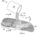
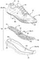
도 1은, 본 개시의 원리에 따른 신발류 물품의 상부 사시도이고;
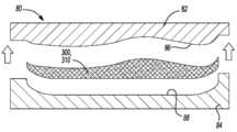
도 2는, 입자형 소재를 내포하며 그리고 바닥창의 내측 표면과 중창의 바닥 표면 사이의 캐비티 내부에 수용되는 케이스를 도시하는, 도 1의 신발류 물품의 분해도이며;
도 3은, 입자형 소재를 내포하며 그리고 바닥창의 내측 표면과 중창의 바닥 표면 사이의 캐비티 내부에 수용되는 케이스를 도시하는, 도 1의 3-3 선을 따라 취해진 단면도이고;
도 4는, 케이스에 대해 이동 가능한 제1 양의 입자형 소재 및 케이스 내로 연장되는 탄성중합체 재료에 부착되는 제2 양의 입자형 소재를 도시하는, 도 3의 구조물의 일부분에 대한 상세 단면도이며; 도 5는, 본 개시의 원리에 따른 신발류 물품의 상부 사시도이고;
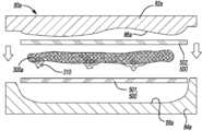
도 6은, 입자형 소재를 내포하며 그리고 바닥창의 내측 표면과 중창의 바닥 표면 사이의 캐비티 내부에 수용되는, 케이스를 에워싸는 완충 재료를 제공하는 완충 부재를 도시하는, 도 5의 신발류 물품의 분해도이며;
도 7은, 완충 재료 내부에 에워싸이며 그리고 입자형 소재를 내포하는 케이스를 도시하는, 도 5의 신발류 물품의 완충 부재의 평면도이고;
도 8은, 케이스에 대해 이동 가능한 제1 양의 입자형 소재 및 케이스 내로 연장되는 탄성중합체 재료에 부착되는 제2 양의 입자형 소재를 내포하는, 케이스를 에워싸는 완충 재료를 도시하는, 도 5의 8-8 선을 따라 취해진 부분 단면도이며;
도 9는, 본 개시의 원리에 따른 신발류 물품의 상부 사시도이고;
도 10은, 바닥창의 내측 표면과 중창의 바닥 표면 사이의 캐비티 내부에 수용되는, 케이스의 외부 표면에 부착되는 제1 발포체 세그먼트들을 도시하는, 도 9의 신발류 물품의 분해도이며;
도 11은, 바닥창의 내측 표면과 중창의 바닥 표면 사이의 캐비티 내부에 수용되는, 케이스의 외부 표면에 부착되는 제1 발포체 세그먼트들을 도시하는, 도 9의 10-10 선을 따라 취해진 부분 단면도이고;
도 12는, 본 개시의 원리에 따른 신발류 물품의 상부 사시도이며;
도 13은, 입자형 소재를 내포하며 그리고 바닥창의 내측 표면과 중창의 바닥 표면 사이의 캐비티 내부에 수용되는 케이스를 도시하는, 도 12의 신발류 물품의 분해도이고;
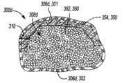
도 14는, 케이스의 내부 공동 내부에 배치되는 분할 벽, 그리고 케이스에 대해 이동 가능한 제1 양의 입자형 소재 및 케이스의 내부 공동 내로 연장되는 탄성중합체 재료에 부착되는 제2 양의 입자형 소재를 도시하는, 도 13의 14-14 선을 따라 취해진 단면도이며;
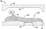
도 15는, 본 개시의 원리에 따른, 케이스의 외부 표면에 탄성중합체 재료를 도포하기 위한 프로세스의 사시도이고;
도 16은, 케이스의 외부 표면 상에 배치되며 그리고 입자형 소재를 내포하는 케이스의 내부 공동 내로 연장되는 탄성중합체 재료를 도시하는, 도 15의 16-16 선을 따라 취해진 단면도이며;
도 17은, 케이스의 외부 표면 상에 탄성중합체 재료를 도포하기 이전의 케이스의 일부분을 도시하는, 도 15의 17-17 선을 따라 취해진 단면도이고;
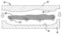
도 18은, 본 개시의 원리에 따른, 몰드가 개방될 때의, 몰드의 위쪽 몰드 부분과 몰드의 아래쪽 몰드 부분 사이에 배치되는 케이스를 도시하는, 몰드의 개략도이며;
도 19는, 몰드가 폐쇄될 때의, 위쪽 몰드 부분과 아래쪽 몰드 부분 사이에 배치되는 케이스를 도시하는, 도 18의 몰드의 개략도이고;
도 20은, 개방된 몰드 및, 위쪽 몰드 부분과 아래쪽 몰드 부분에 의해 부과되는 형상을 구비하도록 성형된 케이스를 도시하는, 도 18의 몰드의 개략도이며;
도 21은, 본 개시의 원리에 따른, 몰드가 개방될 때의, 몰드의 위쪽 몰드 부분과 몰드의 아래쪽 몰드 부분 사이에 배치되는 케이스 그리고 제1 층의 완충 재료 및 제2 층의 완충 재료를 도시하는, 몰드의 개략도이고;
도 22는, 몰드가 폐쇄될 때의, 위쪽 몰드 부분과 아래쪽 몰드 부분 사이에 배치되는 케이스 그리고 제1 층의 완충 재료 및 제2 층의 완충 재료를 도시하는, 도 21의 몰드의 개략도이며;
도 23은, 개방된 몰드 및, 위쪽 몰드 부분과 아래쪽 몰드 부분에 의해 부과되는 형상을 구비하는 완충 부재를 형성하기 위해 케이스에 부착되는 제1 층의 완충 재료 및 제2 층의 완충 재료 도시하는, 도 21의 몰드의 개략도이고;
도 24는, 본 개시의 원리에 따른, 몰드가 개방될 때의, 몰드의 위쪽 몰드 부분과 몰드의 아래쪽 몰드 부분 사이에 배치되는 케이스 및 발포체 세그먼트들을 도시하는, 몰드의 개략도이며;
도 25는, 몰드가 폐쇄될 때의, 위쪽 몰드 부분과 아래쪽 몰드 부분 사이에 배치되는 케이스 및 발포체 세그먼트들을 도시하는, 도 24의 몰드의 개략도이고;
도 26은, 개방된 몰드 및, 위쪽 몰드 부분과 아래쪽 몰드 부분에 의해 부과되는 형상을 구비하는, 케이스에 부착되는 발포체 세그먼트들을 도시하는, 도 24의 몰드의 개략도이며;
도 27은, 몰드가 개방될 때의, 케이스의 노출된 표면에 도포되는 탄성중합체 재료를 갖는, 몰드의 위쪽 부분 아래의 몰드의 아래쪽 부분 상에 배치되는 입자형 소재를 내포하는 케이스를 도시하는, 몰드의 개략도이고;
도 28은, 몰드가 개방될 때의, 몰드의 아래쪽 부분 상에 배치되는 동안에 탄성중합체 재료로 코팅되는 케이스의 노출된 표면을 도시하는, 도 27의 몰드의 개략도이며;
도 29는, 몰드가 폐쇄될 때의, 위쪽 몰드 부분과 아래쪽 몰드 부분 사이에 배치되는 케이스 및 탄성중합체 재료를 도시하는, 도 27의 몰드의 개략도이고;
도 30은, 개방된 몰드 및, 위쪽 몰드 부분과 아래쪽 몰드 부분에 의해 부과되는 형상을 구비하는, 케이스의 표면에 부착되는 탄성중합체 재료를 도시하는, 도 27의 몰드의 개략도이며;
도 31은, 케이스에 대해 이동 가능한 제1 양의 입자형 소재 및 케이스의 상부 표면에 인접하게 케이스 내로 연장되는 탄성중합체 재료에 부착되는 제2 양의 입자형 소재를 도시하는, 도 30의 31-31 선을 따라 취해진 개략도를 도시하고;
도 32는, 몰드가 개방될 때의, 케이스의 노출된 표면에 도포되는 탄성중합체 재료를 갖는, 몰드의 위쪽 부분 아래의 몰드의 아래쪽 부분 상에 배치되는 입자형 소재를 내포하는 케이스를 도시하는, 몰드의 개략도이며;
도 33은, 몰드가 개방될 때의, 몰드의 아래쪽 부분 상에 배치되는 동안에 탄성중합체 재료로 코팅되는 케이스의 노출된 표면을 도시하는, 도 32의 몰드의 개략도이고;
도 34는, 몰드가 폐쇄될 때의, 위쪽 몰드 부분과 아래쪽 몰드 부분 사이에 배치되는 케이스 및 탄성중합체 재료를 도시하는, 도 32의 몰드의 개략도이며;
도 35는, 개방된 몰드 및, 위쪽 몰드 부분과 아래쪽 몰드 부분에 의해 부과되는 형상을 구비하는, 케이스의 표면에 부착되는 탄성중합체 재료를 도시하는, 도 22의 몰드의 개략도이고;
도 36은, 케이스에 대해 이동 가능한 제1 양의 입자형 소재 및 케이스의 바닥 표면에 인접하게 케이스 내로 연장되는 탄성중합체 재료에 부착되는 제2 양의 입자형 소재를 도시하는, 도 35의 36-36 선을 따라 취해진 개략도를 도시하며;
도 37은, 본 개시의 원리에 따른 신발류 물품의 상부 사시도이고;
도 38은, 바닥창의 내측 표면 상에 배치되는 입자형 소재를 내포하는 케이스 및 중창을 갖지 않는 밑창 구조물을 도시하는, 도 37의 38-38 선을 따라 취해진 단면도이며;
도 39는, 본 개시의 원리에 따른 신발류 물품의 상부 사시도이고;
도 40은, 각각 입자형 소재를 내포하며 그리고 바닥창의 내측 표면과 중창의 바닥 표면 사이의 캐비티 내부에 수용되는 제1 케이스 및 제2 케이스를 도시하는, 도 39의 신발류 물품의 분해도이며; 그리고
도 41은, 각각 입자형 소재를 내포하며 그리고 바닥창의 내측 표면과 중창의 바닥 표면 사이의 캐비티 내부에 수용되는 제1 케이스 및 제2 케이스를 도시하는, 도 39의 41-41 선을 따라 취해진 단면도이다.
상응하는 참조 부호들이, 도면들 전체에 걸쳐 상응하는 부분들을 지시한다.The drawings described herein are for illustrative purposes only for selected configurations and are not intended to limit the scope of the present disclosure.
1 is a top perspective view of an article of footwear according to the principles of the present disclosure;
FIG. 2 is an exploded view of the article of footwear of FIG. 1, containing a particulate material and showing a case accommodated inside the cavity between the inner surface of the sole and the bottom surface of the midsole;
FIG. 3 is a cross-sectional view taken along line 3-3 of FIG. 1, showing a case containing a particulate material and being accommodated inside the cavity between the inner surface of the sole and the bottom surface of the midsole;
FIG. 4 is a detailed cross-sectional view of a portion of the structure of FIG. 3 showing a first amount of particulate material movable relative to the case and a second amount of particulate material attached to the elastomeric material extending into the case; 5 is a top perspective view of an article of footwear according to the principles of the present disclosure;
FIG. 6 is an exploded view of the article of footwear of FIG. 5, showing a cushioning member that provides a cushioning material surrounding the case, containing a particulate material and housed within a cavity between the inner surface of the sole and the bottom surface of the midsole; ;
7 is a top view of the cushioning member of the article of footwear of FIG. 5, showing a case enclosed inside the cushioning material and enclosing a particulate material;
FIG. 8 is a view of FIG. 5, showing a cushioning material surrounding a case, comprising a first amount of particulate material movable relative to the case and a second amount of particulate material attached to an elastomeric material extending into the case It is a partial sectional view taken along line 8-8;
9 is a top perspective view of an article of footwear according to the principles of the present disclosure;
10 is an exploded view of the article of footwear of FIG. 9, showing the first foam segments attached to the outer surface of the case, received inside the cavity between the inner surface of the sole and the bottom surface of the midsole;
FIG. 11 is a partial cross-sectional view taken along line 10-10 of FIG. 9, showing first foam segments attached to the exterior surface of the case, received inside the cavity between the inner surface of the sole and the bottom surface of the midsole;
12 is a top perspective view of an article of footwear according to the principles of the present disclosure;
13 is an exploded view of the article of footwear of FIG. 12, containing a particulate material and showing a case housed inside a cavity between the inner surface of the sole and the bottom surface of the midsole;
14 shows a partition wall disposed within the interior cavity of the case, and a first amount of particulate material movable relative to the case and a second amount of particulate material attached to the elastomeric material extending into the interior cavity of the case. It is a sectional view taken along line 14-14 in Fig. 13;
15 is a perspective view of a process for applying an elastomeric material to the outer surface of a case, according to the principles of the present disclosure;
FIG. 16 is a cross-sectional view taken along lines 16-16 of FIG. 15, showing the elastomeric material disposed on the outer surface of the case and extending into the inner cavity of the case containing the particulate material;
17 is a cross-sectional view taken along line 17-17 of FIG. 15, showing a portion of the case prior to applying the elastomeric material on the exterior surface of the case;
18 is a schematic view of a mold, showing a case disposed between the upper mold portion of the mold and the lower mold portion of the mold when the mold is opened, according to the principles of the present disclosure;
19 is a schematic view of the mold of FIG. 18 showing the case disposed between the upper mold portion and the lower mold portion when the mold is closed;
20 is a schematic view of the mold of FIG. 18, showing an open mold and a case molded to have a shape imposed by the upper mold portion and the lower mold portion;
21 shows a case disposed between the upper mold portion of the mold and the lower mold portion of the mold when the mold is opened, according to the principles of the present disclosure, and the buffer material of the first layer and the buffer material of the second layer It is a schematic view of the mold;
22 is a schematic view of the mold of FIG. 21, showing the case disposed between the upper mold portion and the lower mold portion when the mold is closed, and the buffer material of the first layer and the buffer material of the second layer;
23 shows the first layer of buffer material and the second layer of buffer material attached to the case to form a buffer member having an open mold and a shape imposed by the upper mold portion and the lower mold portion, 21 is a schematic view of the mold;
24 is a schematic view of a mold, showing the case and foam segments disposed between the upper mold portion of the mold and the lower mold portion of the mold when the mold is opened, according to the principles of the present disclosure;
25 is a schematic view of the mold of FIG. 24 showing the case and foam segments disposed between the upper mold portion and the lower mold portion when the mold is closed;
FIG. 26 is a schematic view of the mold of FIG. 24 showing the foam segments attached to the case, having an open mold and a shape imposed by the upper mold portion and the lower mold portion;
FIG. 27 shows a case containing a particulate material disposed on the lower portion of the mold below the upper portion of the mold, with the elastomeric material applied to the exposed surface of the case when the mold is opened, It is a schematic of the mold;
28 is a schematic view of the mold of FIG. 27 showing the exposed surface of the case coated with the elastomeric material while being placed on the lower portion of the mold when the mold is open;
29 is a schematic view of the mold of FIG. 27 showing the case and the elastomeric material disposed between the upper mold portion and the lower mold portion when the mold is closed;
FIG. 30 is a schematic view of the mold of FIG. 27 showing the elastomeric material attached to the surface of the case, having an open mold and a shape imposed by the upper mold portion and the lower mold portion;
FIG. 31 shows 31- of FIG. 30, showing a first amount of particulate material that is moveable relative to the case and a second amount of particulate material attached to the elastomeric material extending into the case adjacent to the top surface of the case Showing a schematic diagram taken along
FIG. 32 shows a case containing a particulate material disposed on the lower portion of the mold below the upper portion of the mold, with the elastomeric material applied to the exposed surface of the case when the mold is opened, It is a schematic of the mold;
FIG. 33 is a schematic view of the mold of FIG. 32 showing the exposed surface of the case coated with the elastomeric material while being placed on the bottom portion of the mold when the mold is open;
FIG. 34 is a schematic view of the mold of FIG. 32 showing the case and the elastomeric material disposed between the upper mold portion and the lower mold portion when the mold is closed;
FIG. 35 is a schematic view of the mold of FIG. 22 showing the elastomeric material attached to the surface of the case, having an open mold and a shape imposed by the upper mold portion and the lower mold portion;
FIG. 36 shows 36- of FIG. 35, showing a first amount of particulate material movable relative to the case and a second amount of particulate material attached to the elastomeric material extending into the case adjacent to the bottom surface of the case Showing a schematic diagram taken along
37 is a top perspective view of an article of footwear according to the principles of the present disclosure;
FIG. 38 is a cross-sectional view taken along line 38-38 of FIG. 37, showing a case containing a particulate material disposed on the inner surface of the sole and a sole structure having no midsole;
39 is a top perspective view of an article of footwear according to the principles of the present disclosure;
FIG. 40 is an exploded view of the article of footwear of FIG. 39, each containing a particulate material and showing a first case and a second case accommodated inside the cavity between the inner surface of the sole and the bottom surface of the midsole; And
FIG. 41 is a cross-sectional view taken along line 41-41 of FIG. 39, each showing a first case and a second case that contain a particulate material and are housed inside the cavity between the inner surface of the sole and the bottom surface of the midsole. to be.
Corresponding reference signs indicate corresponding parts throughout the drawings.
예시적 구성들이 지금부터, 첨부 도면들을 참조하여 더욱 완전하게 설명될 것이다. 예시적 구성들은, 본 개시가 철저하도록, 그리고 본 개시의 범위를 당업자에게 완전하게 전달하도록, 제공된다. 구체적인 세부사항들은, 본 개시의 구성들에 대한 철저한 이해를 제공하기 위해, 구체적인 구성요소들, 장치들, 및 방법들에 대한 예들로서 기술된다. 구체적인 세부사항들이 사용될 필요가 없다는 것, 그러한 예시적 구성들이 많은 상이한 형태들로 실시될 수 있다는 것, 및 구체적인 세부사항들 및 예시적인 구성들이 본 개시의 범위를 제한하는 것으로 해석되지 않아야 한다는 것이, 당업자에게 명백할 것이다.Exemplary configurations will now be more fully described with reference to the accompanying drawings. Exemplary configurations are provided to make the present disclosure thorough and to fully convey the scope of the present disclosure to those skilled in the art. Specific details are described as examples of specific components, devices, and methods, to provide a thorough understanding of the configurations of the present disclosure. That specific details do not need to be used, such example configurations can be implemented in many different forms, and that specific details and example configurations should not be construed as limiting the scope of the present disclosure, It will be apparent to those skilled in the art.
여기에서 사용되는 전문용어는, 단지 특정 예시적 구성들을 설명할 목적이며 그리고 제한하는 것으로 의도되지 않는다. 여기에서 사용되는 바와 같은, 단수형 관사들 "부정관사" 및 "정관사"는, 문맥이 분명하게 달리 지시하지 않는 한, 복수 형태를 또한 포함하는 것으로 의도될 수 있을 것이다. 용어들 "포함한다", "포함하는", "구비하는", 및 "가지는"은, 포괄적이며 그리고 그에 따라 특징들, 단계들, 작동들, 요소들, 및/또는 구성요소들의 존재를 구체화하지만, 하나 이상의 다른 특징들, 단계들, 작동들, 요소들, 구성요소들, 및/또는 이들의 그룹들의 존재 또는 부가를 배제하지 않는다. 본 명세서에서 설명되는 방법 단계들, 프로세스들, 및 작동들은, 실행의 순서로서 구체적으로 식별되지 않는 한, 논의되거나 예시되는 특정 순서에 따른 그들의 실행을 반드시 요구하는 것으로 해석되지 않아야 한다. 부가적인 또는 대안적인 단계들이 사용될 수 있을 것이다.The terminology used herein is for the purpose of describing only certain exemplary configurations and is not intended to be limiting. As used herein, singular articles “negative article” and “definite article” may be intended to include plural forms also, unless the context clearly dictates otherwise. The terms “comprises”, “comprising”, “having”, and “having” are inclusive and thus embody the presence of features, steps, acts, elements, and / or components , Does not exclude the presence or addition of one or more other features, steps, acts, elements, components, and / or groups thereof. The method steps, processes, and acts described herein should not be construed as requiring their execution in a particular order discussed or illustrated, unless specifically identified as the order of execution. Additional or alternative steps may be used.
요소 또는 층이 다른 요소 또는 층, "상에" 놓이는, "에 맞물리는", "에 연결되는", "에 부착되는" 또는 "에 결합되는" 것으로 언급될 때, 요소 또는 층은, 직접적으로 다른 요소 또는 층, 상에 놓일 수, 에 맞물릴 수, 에 연결될 수, 에 부착될 수 또는 에 결합될 수 있으며, 또는 개입하는 요소들 또는 층들이 존재할 수 있을 것이다. 대조적으로, 요소가 다른 요소 또는 층 "상에 직접적으로" 놓이는, "에 직접적으로 맞물리는", "에 직접적으로 연결되는", "에 직접적으로 부착되는" 또는 "에 직접적으로 결합되는" 것으로 언급될 때, 개입하는 요소들 또는 층들이 존재하지 않을 것이다. 요소들 간의 관계를 설명하기 위해 사용되는 다른 단어들은, (예를 들어, "사이에" 대 "직접적으로 사이에", "인접한" 대 "직접적으로 인접한", 등의) 유사한 형태로 해석되어야만 한다. 여기에서 사용되는 바와 같은, 용어 "및/또는"은, 하나 이상의 연관된 열거된 품목의 임의의 그리고 모든 조합을 포함한다.When an element or layer is referred to as another element or layer, "on", "engaged to", "connected to", "attached to" or "coupled to", the element or layer directly Other elements or layers, can be put on, can be engaged on, can be connected to, can be attached to or can be coupled to, or intervening elements or layers may be present. In contrast, an element is referred to as being “directly engaged”, “directly connected to”, “directly attached to” or “directly coupled to”, “directly on” another element or layer. When possible, there will be no intervening elements or layers. Other words used to describe the relationship between the elements should be interpreted in a similar fashion (eg, “between” vs. “directly between”, “adjacent” versus “directly adjacent”, etc.) . As used herein, the term “and / or” includes any and all combinations of one or more associated listed items.
용어들, 제1, 제2, 제3 등은, 다양한 요소들, 구성요소들, 영역들, 층들 및/또는 섹션들을 설명하기 위해 본 명세서에서 사용될 수 있을 것이다. 이러한 요소들, 구성요소들, 영역들, 층들 및/또는 섹션들은, 이러한 용어들에 의해 제한되지 않아야 한다. 이러한 용어들은 단지, 하나의 요소, 구성요소, 영역, 층 또는 섹션을, 다른 영역, 층 또는 섹션과 구별하기 위해 사용될 수 있을 것이다. "제1", "제2" 및 다른 수치적 용어들과 같은 용어들은, 문맥에 의해 명백하게 지시되지 않는 한, 순서 또는 순번을 의미하지 않는다. 따라서, 이하에 논의되는 제1 요소, 구성요소, 영역, 층 또는 섹션은, 예시적인 구성들의 교시로부터 벗어남 없이, 제2 요소, 구성요소, 영역, 층 또는 섹션으로 지칭될 수 있다.The terms first, second, third, etc. may be used herein to describe various elements, components, regions, layers and / or sections. These elements, components, regions, layers and / or sections should not be limited by these terms. These terms may only be used to distinguish one element, component, region, layer or section from another region, layer or section. Terms such as “first”, “second” and other numerical terms do not imply order or sequence, unless expressly indicated by context. Accordingly, a first element, component, region, layer or section discussed below may be referred to as a second element, component, region, layer or section, without departing from the teaching of exemplary configurations.
본 개시의 하나의 양태에서, 신발류 물품이, 제공되며 그리고 갑피, 바닥창, 및 중창을 포함한다. 바닥창은, 갑피에 부착되며 그리고, 지면-접촉 표면 및, 바닥창의 지면-접촉 표면 반대편 측부 상에 배치되는 내측 표면을 구비한다. 중창은, 발 받침부 및, 중창의 발 받침부 반대편 측부 상에 배치되며 그리고 그들 사이에 캐비티를 한정하도록 바닥창의 내측 표면에 대향하는, 바닥 표면을 포함한다. 신발류 물품은 또한, 캐비티 내부에 수용되며 그리고 내부 공동을 한정하는, 케이스를 포함한다. 내부 공동은, 케이스에 대해 이동 가능한 제1 양의 입자형 소재 및 케이스에 부착되는 제2 양의 입자형 소재를 내포한다.In one aspect of the present disclosure, an article of footwear is provided and includes an upper, sole, and midsole. The sole is attached to the upper and has a ground-contacting surface and an inner surface disposed on the side opposite the ground-contacting surface of the sole. The midsole includes a footrest and a bottom surface disposed on the side opposite the footrest of the midsole and facing the inner surface of the sole to define a cavity therebetween. The article of footwear also includes a case, which is housed inside the cavity and defines an interior cavity. The inner cavity contains a first amount of particulate material that is movable relative to the case and a second amount of particulate material attached to the case.
케이스는, 가요성 재료로 형성될 수 있을 것이다. 부가적으로 또는 대안적으로, 케이스는, 메시 재료 및/또는 나일론 재료로 형성될 수 있을 것이다.The case may be formed of a flexible material. Additionally or alternatively, the case may be formed of a mesh material and / or nylon material.
일부 구현예에서, 탄성중합체 재료가, 케이스의 표면 상에 배치된다. 예를 들어, 탄성중합체 재료는, 케이스의 외부 표면 상에 배치될 수 있을 것이다. 일부 예에서, 탄성중합체 재료의 적어도 일부분이, 케이스의 내부 공동 내로 연장될 수 있을 것이다. 이러한 예들에서, 제2 양의 입자형 소재는, 탄성중합체 재료에 부착되는 것에 의해, 케이스에 부착된다. 탄성중합체 재료는, 케이스를 에워쌀 수 있을 것이다. 일부 구성에서, 제1 발포체 세그먼트가, 탄성중합체 재료에 부착된다. 부가적으로 또는 대안적으로, 제2 발포체 세그먼트가 케이스의 내부 공동 내부에 배치될 수 있을 것이다.In some embodiments, an elastomeric material is disposed on the surface of the case. For example, the elastomeric material may be disposed on the outer surface of the case. In some examples, at least a portion of the elastomeric material may extend into the inner cavity of the case. In these examples, the second amount of particulate material is attached to the case by being attached to the elastomeric material. The elastomeric material may enclose the case. In some configurations, the first foam segment is attached to the elastomeric material. Additionally or alternatively, a second foam segment may be placed inside the inner cavity of the case.
입자형 소재는, 발포체 구슬들을 포함할 수 있을 것이다. 여기서, 발포체 구슬들은, 실질적으로 구형 형상 및 실질적으로 다각형 형상 중의 적어도 하나를 구비할 수 있을 것이다. 일부 예에서, 발포체 구슬들은, 동일한 크기 및 형상을 구비한다. 다른 예에서, 발포체 구슬들 중의 적어도 하나는, 상이한 크기 및 형상 중 적어도 하나를 구비한다.The particulate material may include foam beads. Here, the foam beads may have at least one of a substantially spherical shape and a substantially polygonal shape. In some examples, the foam beads have the same size and shape. In another example, at least one of the foam beads has at least one of a different size and shape.
일부 구현예에서, 케이스는, 바닥창의 내측 표면 및 중창의 바닥 표면의 표면 윤곽들에 합치하도록 성형된다. 신발류 물품은 또한, 캐비티 내부에서 케이스와 바닥창의 내측 표면 사이에 배치되는 탄력 부재를 포함할 수 있을 것이다. 일부 구성에서, 신발류 물품은 또한, 적어도 2개의 세그먼트를 한정하기 위해, 내부 공동 내부에 배치되며 그리고 케이스의 벽들에 접합되는, 적어도 하나의 분할 벽을 포함한다. 적어도 2개의 세그먼트는 각각, 제1 양의 입자형 소재의 일부분 및 제2 양의 입자형 소재의 일부분 중의 적어도 하나를 내포할 수 있을 것이다.In some embodiments, the case is shaped to conform to the surface contours of the inner surface of the sole and the bottom surface of the midsole. The article of footwear may also include a resilient member disposed between the case and the inner surface of the sole within the cavity. In some configurations, the article of footwear also includes at least one dividing wall disposed within the interior cavity and joined to the walls of the case, to define at least two segments. Each of the at least two segments may contain at least one of a portion of the first amount of particulate material and a portion of the second amount of particulate material.
본 개시의 다른 양태에서, 신발류 물품이, 제공되며 그리고 갑피, 바닥창, 및 중창을 포함한다. 바닥창은, 갑피에 부착되며 그리고, 지면-접촉 표면 및, 바닥창의 지면-접촉 표면 반대편 측부 상에 배치되는 내측 표면을 구비한다. 중창은, 발 받침부 및, 중창의 발 받침부 반대편 측부 상에 배치되는, 바닥 표면을 구비한다. 바닥 표면은, 캐비티를 그들 사이에 한정하기 위해, 바닥창의 내측 표면과 대향한다. 신발류 물품은 또한, 탄성중합체 재료 내부에 배치되며 그리고 캐비티 내부에 수용되는 케이스를 포함한다. 케이스는, 탄성중합체 재료에 의해 케이스에 고착되는 제1 부분의 입자형 소재를 포함한다.In another aspect of the present disclosure, an article of footwear is provided and includes an upper, sole, and midsole. The sole is attached to the upper and has a ground-contacting surface and an inner surface disposed on the side opposite the ground-contacting surface of the sole. The midsole has a footrest and a bottom surface disposed on the side opposite the footrest of the midsole. The floor surface faces the inner surface of the sole, to define the cavity between them. The article of footwear also includes a case disposed inside the elastomeric material and housed inside the cavity. The case includes a particulate material of the first portion that is fixed to the case by an elastomeric material.
일부 구현예에서, 입자형 소재는, 케이스에 대해 이동 가능한 제2 부분을 포함한다. 입자형 소재는, 발포체 구슬들을 포함할 수 있을 것이다. 여기서, 발포체 구슬들은, 실질적으로 구형 형상 및 실질적으로 다각형 형상 중의 적어도 하나를 구비할 수 있을 것이다. 일부 예에서, 발포체 구슬들은, 동일한 크기 및 형상을 구비한다. 다른 예에서, 발포체 구슬들 중의 적어도 하나는, 상이한 크기 및 형상 중 적어도 하나를 구비한다. 케이스는, 가요성 재료로 형성될 수 있을 것이다. 부가적으로 또는 대안적으로, 케이스는, 다공성 재료로 형성될 수 있을 것이다. 탄성중합체 재료는, 액체로서 케이스의 외부 표면들에 도포될 수 있을 것이다. 일부 예에서, 탄성중합체 재료의 적어도 일부분이, 케이스 내로 연장된다. 부가적으로 또는 대안적으로, 탄성중합체 재료의 적어도 일부분이, 케이스를 에워쌀 수 있을 것이다.In some embodiments, the particulate material includes a second portion that is movable relative to the case. The particulate material may include foam beads. Here, the foam beads may have at least one of a substantially spherical shape and a substantially polygonal shape. In some examples, the foam beads have the same size and shape. In another example, at least one of the foam beads has at least one of a different size and shape. The case may be formed of a flexible material. Additionally or alternatively, the case may be formed of a porous material. The elastomeric material may be applied to the outer surfaces of the case as a liquid. In some examples, at least a portion of the elastomeric material extends into the case. Additionally or alternatively, at least a portion of the elastomeric material may surround the case.
일부 구성에서, 소정량의 발포체 세그먼트들이, 케이스 내부에 배치된다. 발포체 세그먼트들은, 발포체 구슬들과 상이한 크기 및 형상을 구비할 수 있을 것이다. 소정량의 발포체 세그먼트들은, 케이스에 대해 이동 가능할 수 있을 것이다. 그러나, 다른 구성에서, 소정량의 발포체 세그먼트들 중의 적어도 일부분은, 탄성중합체 재료에 의해 케이스에 고착된다. 일부 구현예에서, 완충 재료가, 케이스를 에워싼다.In some configurations, a predetermined amount of foam segments are disposed inside the case. The foam segments may have different sizes and shapes than foam beads. The predetermined amount of foam segments may be movable relative to the case. However, in other configurations, at least a portion of the predetermined amount of foam segments are secured to the case by an elastomeric material. In some embodiments, a cushioning material surrounds the case.
신발류 물품은 또한, 각각 개별적인 양의 입자형 소재를 내포하는 적어도 2개의 세그먼트를 한정하기 위해, 내부 공동 내부에 배치되며 그리고 케이스의 벽들에 접합되는, 분할 벽을 포함할 수 있을 것이다. 일부 예에서, 케이스는, 바닥창의 내측 표면 및 중창의 바닥 표면의 표면 윤곽들에 합치하도록 성형된다. 일부 구현예에서, 신발류 물품은 또한, 캐비티 내부에서 케이스와 바닥창의 내측 표면 사이에 배치되는 탄력 부재를 포함한다.The article of footwear may also include a partition wall, disposed inside the inner cavity and joined to the walls of the case, to define at least two segments each containing a separate amount of particulate material. In some examples, the case is shaped to conform to the surface contours of the inner surface of the sole and the bottom surface of the midsole. In some embodiments, the article of footwear also includes an elastic member disposed within the cavity between the case and the inner surface of the sole.
본 개시의 또 다른 양태에서, 신발류 물품을 제조하는 방법이, 제공되며, 그리고 발 받침부와 바닥창 사이에 캐비티를 제공하는 것을 포함한다. 방법은 또한, 케이스에 대해 이동 가능한 제1 양의 입자형 소재 및 케이스에 부착되는 제2 양의 입자형 소재를 내포하는 케이스를 제공하는 것, 및 케이스를 캐비티 내에 삽입하는 것을 포함한다.In another aspect of the present disclosure, a method of manufacturing an article of footwear is provided and includes providing a cavity between a footrest and a sole. The method also includes providing a case containing a first amount of particulate material that is movable relative to the case and a second amount of particulate material attached to the case, and inserting the case into the cavity.
일부 구현예에서, 방법은 또한, 다공성 재료로 케이스를 형성하는 것 및/또는 가요성 재료로 케이스를 형성하는 것을 포함한다. 일부 예에서, 방법은 또한, 케이스의 외부 표면의 적어도 일부분을 탄성중합체 재료로 코팅하는 것을 포함한다. 이러한 예들에서, 케이스를 탄성중합체 재료로 코팅하는 것은, 케이스를 액체 탄성중합체 재료로 코팅하는 것을 포함할 수 있을 것이다. 여기서, 액체 탄성중합체 재료는, 경화될 수 있을 것이다. 일부 구성에서, 방법은 또한, 케이스에 제2 양의 입자형 소재를 부착하기 위해 제2 양의 입자형 소재에 탄성중합체 재료를 부착하는 것을 포함한다.In some embodiments, the method also includes forming the case with a porous material and / or forming the case with a flexible material. In some examples, the method also includes coating at least a portion of the exterior surface of the case with an elastomeric material. In these examples, coating the case with an elastomeric material may include coating the case with a liquid elastomeric material. Here, the liquid elastomeric material may be curable. In some configurations, the method also includes attaching an elastomeric material to the second amount of particulate material to attach the second amount of particulate material to the case.
방법은, 케이스를 제1 완충 재료로 에워싸는 것을 포함할 수 있을 것이다. 예를 들어, 케이스는, 탄성중합체 재료를 통해 케이스에 제1 완충 재료를 부착하는 것에 의해, 제1 완충 재료로 에워싸이게 될 수 있을 것이다. 일부 예에서, 방법은, 케이스의 내부 공동 내부에 배치되며 그리고 케이스의 벽들에 접합되는 인장 부재를 제공하는 것을 포함한다. 방법은 또한, 케이스에 정해진 양의 발포체 구슬들을 제공하는 것에 의해, 제1 양의 입자형 소재 및 제2 양의 입자형 소재를 제공하는 것을 포함할 수 있을 것이다. 발포체 구슬들을 제공하는 것은, 실질적으로 구형 형상 및 실질적으로 다각형 형상 중의 적어도 하나를 구비하는 발포체 구슬들을 제공하는 것을 포함할 수 있을 것이다. 더불어, 발포체 구슬들을 제공하는 것은, 동일한 크기 및 형상을 구비하는 발포체 구슬들을 제공하는 것을 포함할 수 있을 것이다. 부가적으로 또는 대안적으로, 발포체 구슬들을 제공하는 것은, 상이한 크기 및 형상 중 적어도 하나를 구비하는 발포체 구슬들을 제공하는 것을 포함할 수 있을 것이다.The method may include surrounding the case with a first cushioning material. For example, the case may be enclosed with the first cushioning material by attaching the first cushioning material to the case through the elastomeric material. In some examples, the method includes providing a tension member disposed within the interior cavity of the case and bonded to the walls of the case. The method may also include providing a first amount of particulate material and a second amount of particulate material by providing a predetermined amount of foam beads to the case. Providing foam beads may include providing foam beads having at least one of a substantially spherical shape and a substantially polygonal shape. In addition, providing foam beads may include providing foam beads having the same size and shape. Additionally or alternatively, providing foam beads may include providing foam beads having at least one of a different size and shape.
일부 예에서, 방법은, 각각 제1 양의 입자형 소재의 일부분 및 제2 양의 입자형 소재의 일부분 중의 적어도 하나를 내포하는 적어도 2개의 세그먼트를 한정하도록 케이스의 벽들을 함께 고정하는 것을 더 포함한다.In some examples, the method further includes securing the walls of the case together to define at least two segments containing at least one of a portion of the first amount of particulate material and a portion of the second amount of particulate material, respectively. do.
본 개시의 다른 양태에서, 신발류 물품을 제조하는 방법이, 발 받침부와 바닥창 사이에 캐비티를 제공하는 것, 및 제1 양의 입자형 소재를 내포하는 케이스를 제공하는 것을 포함한다. 방법은 또한, 케이스의 외부 표면을 탄성중합체 재료로 코팅하는 것, 탄성중합체 재료를 경화하는 것, 및 케이스를 캐비티 내로 삽입하는 것을 포함한다.In another aspect of the present disclosure, a method of manufacturing an article of footwear includes providing a cavity between a footrest and a sole, and providing a case containing a first amount of particulate material. The method also includes coating the outer surface of the case with an elastomeric material, curing the elastomeric material, and inserting the case into the cavity.
일부 구현예에서, 방법은 또한, 다공성 재료로 케이스를 형성하는 것을 포함한다. 부가적으로 또는 대안적으로, 방법은, 가요성 재료로 케이스를 형성하는 것을 포함할 수 있을 것이다. 일부 예에서, 방법은 또한, 케이스를 제1 완충 재료 내에 에워싸는 것을 포함한다 이러한 예들에서, 방법은, 탄성중합체 재료를 통해 케이스를 제1 완충 재료에 부착하는 것에 의해 케이스를 제1 완충 재료로 에워싸는 것을 포함할 수 있을 것이다. 부가적으로 또는 대안적으로, 방법은, 케이스의 내부 공동 내부에 배치되며 그리고 케이스의 벽들에 접합되는 인장 부재를 제공하는 것을 포함할 수 있을 것이다.In some embodiments, the method also includes forming a case with a porous material. Additionally or alternatively, the method may include forming the case with a flexible material. In some examples, the method also includes enclosing the case in the first cushioning material. In these examples, the method wraps the case with the first cushioning material by attaching the case to the first cushioning material through an elastomeric material. It may contain things. Additionally or alternatively, the method may include providing a tension member disposed within the interior cavity of the case and bonded to the walls of the case.
방법은 또한, 케이스에 제2 양의 입자형 소재를 제공하는 것을 포함할 수 있을 것이다. 일부 예에서, 방법은, 탄성중합체 재료를 통해 제2 양의 입자형 소재를 케이스에 부착하는 것을 포함한다. 일부 구성에서, 케이스의 외부 표면을 코팅하는 것은, 탄성중합체 재료가 케이스에 진입하도록 그리고 제2 양의 입자형 소재와 접촉하도록 야기한다. 일부 예에서, 방법은, 각각 제1 양의 입자형 소재의 일부분 및 제2 양의 입자형 소재의 일부분 중의 적어도 하나를 내포하는 적어도 2개의 세그먼트를 한정하도록 케이스의 벽들을 함께 고정하는 것을 포함한다.The method may also include providing a second amount of particulate material to the case. In some examples, the method includes attaching a second amount of particulate material to the case through the elastomeric material. In some configurations, coating the outer surface of the case causes the elastomeric material to enter the case and contact the second amount of particulate material. In some examples, the method includes securing the walls of the case together to define at least two segments containing at least one of a portion of the first amount of particulate material and a portion of the second amount of particulate material, respectively. .
일부 구현예에서, 제1 양의 입자형 소재 및 제2 양의 입자형 소재를 제공하는 것은, 케이스에 정해진 양의 발포체 구슬들을 제공하는 것을 포함한다. 발포체 구슬들을 제공하는 것은, 실질적으로 구형 형상 및 실질적으로 다각형 형상 중의 적어도 하나를 구비하는 발포체 구슬들을 제공하는 것을 포함할 수 있을 것이다. 다른 예에서, 정해진 양의 발포체 구슬들을 제공하는 것은, 동일한 크기 및 형상을 구비하는 발포체 구슬들을 제공하는 것을 포함한다. 부가적으로 또는 대안적으로, 발포체 구슬들을 제공하는 것은, 상이한 크기 및 형상 중 적어도 하나를 구비하는 발포체 구슬들을 제공하는 것을 포함한다.In some embodiments, providing the first amount of particulate material and the second amount of particulate material includes providing a defined amount of foam beads to the case. Providing foam beads may include providing foam beads having at least one of a substantially spherical shape and a substantially polygonal shape. In another example, providing a predetermined amount of foam beads includes providing foam beads having the same size and shape. Additionally or alternatively, providing foam beads includes providing foam beads having at least one of a different size and shape.
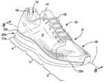
도 1 내지 도 4를 참조하면, 신발류 물품(10)이, 제공되며 그리고, 갑피(100) 및 갑피(100)에 부착되는 밑창 구조물(200)을 포함한다. 신발류 물품(10)은, 하나 이상의 부분으로 분할될 수 있을 것이다. 부분들은, 전족 부분(12), 중족 부분(14), 및 뒤꿈치 부분(16)을 포함할 수 있을 것이다. 전족 부분(12)은, 발가락들 및 중족골들(metatarsal bones)을 발의 지골들(phalanx bones)과 연결하는 관절들에 대응할 수 있을 것이다. 중족 부분(14)은, 발의 아치 영역에 대응할 수 있으며, 그리고 뒤꿈치 부분(16)은, 종골(calcaneus bone)을 포함하는 발의 뒤쪽 부분들에 대응할 수 있을 것이다. 신발류(10)는, 신발류(10)의 반대편 측부들에 대응하며 그리고 부분들(12, 14, 16)을 통해 연장되는, 바깥쪽 측부 및 안쪽 측부(18, 20)를 포함할 수 있을 것이다.1 to 4, a
갑피(100)는, 밑창 구조물(200) 상에서의 지지를 위해 발을 수용하고 고정하는 내부 공동(102)을 한정하는, 내부 표면들을 포함한다. 뒤꿈치 부분(16) 내의 발목 개구부(104)가, 내부 공동(102)에 대한 접근을 제공할 수 있을 것이다. 예를 들어, 발목 개구부(104)는, 공동(102) 내부에 발을 고정하기 위해 발을 수용할 수 있으며, 그리고 내부 공동(102)으로부터 그리고 내부 공동(102)으로의 발의 진입 및 진출을 가능하게 한다. 일부 예에서, 하나 이상의 잠금구(106)가, 동시에 내부 공간으로부터의 발의 진입 및 진출을 수용하는 가운데, 발 둘레에서의 내부 공동(102)의 맞춤을 조절하기 위해 갑피(100)를 따라 연장된다. 갑피(100)는, 잠금구들(106)을 수용하는, 아일렛들(eyelets)과 같은 구멍들 및/또는 직물 루프 또는 메시 루프(mesh loop)와 같은 다른 상관 특징부들(other engagement features)을 포함할 수 있을 것이다. 잠금구들(106)은, 레이스들, 스트랩들, 코드들, 후크-앤-루프(hook-and-loop), 또는 임의의 다른 적당한 유형의 잠금구를 포함할 수 있을 것이다.The upper 100 includes interior surfaces, defining an
갑피(100)는, 내부 공동(102)과 잠금구들(106) 사이에서 연장되는, 텅 부분(110)을 포함할 수 있을 것이다. 갑피(100)는, 내부 공동(102)을 형성하기 위해 바느질되거나 또는 접착식으로 접합되는, 하나 이상의 재료들로 형성될 수 있을 것이다. 갑피의 적당한 재료들은, 이에 국한되는 것은 아니지만, 직물, 발포체, 가죽, 및 인조 가죽을 포함할 수 있을 것이다. 재료들은, 내구성, 통기성, 마모-저항성, 유연성 및 안락함의 특성들을 부과하도록, 선택되고 배치될 수 있을 것이다.The upper 100 may include a
일부 구현예에서, 밑창 구조물(200)은, 적층된 구성으로 배열되는 바닥창(210) 및 중창(220)을 포함한다. 밑창 구조물(200)(예를 들어, 바닥창(210) 및 중창(220))은, 종방향 축(L)을 한정한다. 예를 들어, 바닥창(210)은, 신발류 물품(10)의 사용 도중에 지표면과 접촉하며, 그리고 중창(220)은, 갑피(100)와 바닥창(210) 사이에 배치된다. 일부 예에서, 밑창 구조물(200)은 또한, 신발류(10)의 안락함을 향상시키기 위해 발의 발바닥 표면을 수용하도록 갑피(100)의 내부 공동(102) 내부에 상주할 수 있는, 안창 또는 깔창(미도시)과 같은 부가적인 층들을 통합할 수 있을 것이다. 일부 예에서, 측벽(230)이, 바닥창(210)의 둘레를 둘러싸며 그리고 바닥창(210)과 중창(220)을 그들 사이에 캐비티(240)를 한정하기 위해 분리한다.In some implementations, the
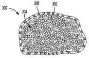
일부 구성에서, 캐비티(240)는, 신발류(10)의 사용 도중에 발을 위한 완충을 제공하기 위한 입자형 소재(350)를 내포하는, 케이스(300)를 수용한다. 케이스(300)는, 밑창 구조물(200)의 종방향 축(L)에 실질적으로 평행하게 연장되는 길이를 한정할 수 있으며, 그리고 발의 바닥 표면뿐만 아니라 바닥창(210)의 내측 표면(214)의 윤곽에 합치하는 윤곽을 제공하도록 형성될 수 있을 것이다. 일부 예에서, 케이스(300)는, 메시 및/또는 다른 적당한 다공성 직물들과 같은, 다공성 재료로 형성된다. 부가적으로 또는 대안적으로, 케이스(300)는 가요성 재료로 형성될 수 있을 것이다.In some configurations, the
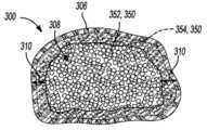
케이스(300)의 외부 표면(306)이, 케이스(300)에 가요성 외측 피복을 제공하기 위해 탄성중합체 재료(310)로 코팅될 수 있을 것이다. 예를 들어, 탄성중합체 재료(310)는, 케이스(300)가 요구되는 형상 및 구성을 갖도록 형성될 때 경화되는, 액체로서 도포될 수 있을 것이다(즉, 케이스(300)는, 바닥창(210)의 내측 표면(214) 및/또는 중창(220)의 바닥 표면(222)의 표면 윤곽들에 합치하도록 케이스를 성형함에 의해 형성될 수 있음). 그에 따라, 케이스(300) 상에 배치되는 탄성중합체 재료(310)는, 상기한 방식으로 형성되는 케이스(300)를 에워쌀 수 있으며 그리고 일단 경화되면 케이스(300)에 외측 피복을 제공할 수 있을 것이다.The
케이스(300)의 다공성은, 액체 탄성중합체 재료(310)의 적어도 일부분이 (케이스(300)에 도포될 때) 케이스(300) 내로 그리고 그 내부에 상주하는 입자형 소재(350)의 일부분과의 접촉 상태로 연장되는 것을 허용할 수 있을 것이다. 이러한 예들에서, 탄성중합체 재료(310)가 경화될 때, 탄성중합체 재료(310)는, 케이스(300)의 외부 표면(306)에 그리고 또한 케이스(300) 내부에 배치되는 입자형 소재(350)의 일부분에 접착될 수 있을 것이다. 말하자면, 케이스(300)의 재료에 인접하게 배치되는 입자형 소재(350)의 일부분이, 케이스(300) 내로 연장되는 탄성중합체 재료(310)와 접촉할 것이다. 그에 따라, 탄성중합체 재료(310)와 접촉하는 입자형 소재(350)의 일부분은, 탄성중합체 재료(310)를 통해 케이스(300)에 부착될 수 있을 것이다. 탄성중합체 재료(310)를 통해 케이스(300)에 부착되는 입자형 소재(350)는, 탄성중합체 재료(310)에 의해 케이스(300)에 대해 이동하는 것이 방지된다. 역으로, 탄성중합체 재료(310)에 노출되지 않는 입자형 소재(350)의 다른 부분들은, 케이스(300)에 대해 이동하는 것이 허용된다. 따라서, 입자형 소재(350)가, 탄성중합체 재료(310)에 의해 케이스(300)에 부착되는 부분들을 포함할 수 있는 가운데, 탄성중합체 재료(310)로부터 이격되는 입자형 소재(350)의 다른 부분들은, 바닥창의 지면-접촉 표면(212)이 뒤꿈치 부분(16)과 전족 부분(12) 사이에서 지표면과의 맞물림을 위해 구를 때, 점진적인 완충을 제공하기 위해 케이스(300)에 대해 그리고 케이스(300) 내부에서 이주 및 이동하는 것이 허용된다.The porosity of the
탄성중합체 재료는, 이에 국한되는 것은 아니지만, 니트릴 고무, 염소화 폴리에틸렌, 네오프렌(클로로프렌 중합체), 클로로술포닐 폴리에틸렌(하이팔론), 에틸렌 에테르 폴리설파이드, 에틸렌 폴리설파이드, 에틸렌 프로필렌 공중합체(EPM), 에틸렌 프로필렌 삼원 공중합체(EPDM), 불화 탄화수소, 플루오로실리콘, 이소부틸렌 이소프렌, 오르가노폴리실록산, 아크릴 고무, 폴리부타디엔, 폴리에피클로로히드렌, 천연 고무, 합성 이소프렌, 우레탄 고무(폴리우레탄(폴리 에스테르) 및 폴리우레탄(폴리 에테르) 양자 모두)를 포함할 수 있을 것이다.Elastomer materials include, but are not limited to, nitrile rubber, chlorinated polyethylene, neoprene (chloroprene polymer), chlorosulfonyl polyethylene (hypalon), ethylene ether polysulfide, ethylene polysulfide, ethylene propylene copolymer (EPM), ethylene Propylene terpolymer (EPDM), fluorinated hydrocarbon, fluorosilicone, isobutylene isoprene, organopolysiloxane, acrylic rubber, polybutadiene, polyepichlorohydrene, natural rubber, synthetic isoprene, urethane rubber (polyurethane (polyester ) And polyurethane (polyether).
일부 예에서, 케이스(300) 내부에 내포되는 입자형 소재(350)는, 실질적으로 구형 형상을 갖는 발포체 구슬들을 포함할 수 있을 것이다. 일부 예에서, 입자형 소재(350)는, 동일한 크기 및 형상을 갖는 발포체 구슬들을 포함한다. 다른 예에서, 입자형 소재(350)는, 상이한 크기 및 형상 중 적어도 하나를 갖는 발포체 구슬들을 포함한다. 입자형 소재(350)의 특정 크기 및 형상과 무관하게, 입자형 소재(350)는, 완충 및 응답 성능을 갖는 신발류 물품(10)을 제공하기 위해, 바닥창(210) 및 중창(220)과 협력한다. 일부 예에서, 입자형 소재(350) 및 탄성중합체 재료(310)는, 하나 이상의 재생 가능한 중합체 재료로 형성된다.In some examples, the
바닥창(210)은, 지면-접촉 표면(212) 및 반대편 내측 표면(214)을 포함할 수 있을 것이다. 바닥창(210)은, 갑피(100)에 부착될 수 있을 것이다. 일부 예에서, 측벽(230)은, 바닥창(210)의 둘레로부터 연장되며 그리고 중창(220) 또는 갑피(100)에 부착된다. 도 1의 예는, 전족 부분(12)의 끝단 근처에서 갑피(100)에 부착되는 바닥창(210)을 도시한다. 바닥창(210)은 일반적으로, 신발류 물품(10)의 사용 도중에 마모 저항성 및 지표면에 대한 마찰력을 제공한다. 바닥창(210)은, 내구성 및 마모-저항성을 부과할 뿐만 아니라, 지표면에 대한 마찰력을 향상시키는, 하나 이상의 재료로 형성될 수 있을 것이다. 예를 들어, 고무가 바닥창(210)의 적어도 일부를 형성할 수 있을 것이다.The sole 210 may include a ground-contacting
중창(220)은, 바닥 표면(222) 및, 중창(220)의 바닥 표면(222) 반대편 측부 상에 배치되는 발 받침부(224)를 포함할 수 있을 것이다. 봉제선(226) 또는 접착제가, 중창(220)을 갑피(100)에 고정할 수 있을 것이다. 발 받침부(224)는, 발의 바닥 표면(예를 들어, 발바닥)의 윤곽에 합치하도록 윤곽 형성될 수 있을 것이다. 바닥 표면(222)은, 그들 사이에 캐비티(240)를 한정하기 위해, 바닥창(210)의 내측 표면(214)과 대향할 수 있을 것이다. 중창(220)은, 중창(220)이 케이스(300) 내부에 배치되며 그리고 캐비티(240) 내에 상주하는 입자형 소재(350)에 합치하는 것을 허용하는, 가요성 재료로 형성될 수 있을 것이다. 그렇게 함으로써, 가요성 중창(220)은, 캐비티(240) 내에 상주하는 입자형 소재(350)가 밑창 구조물(200)의 점진적인 하중 작용 도중에 발의 바닥 표면의 윤곽과 상호작용하는 것을 허용하는, 가요성 판상물(flexible stroble)에 상응할 수 있을 것이다. 일부 예에서, 측벽(230)은, 캐비티(240)의 둘레뿐만 아니라, 바닥 표면(222)과 내측 표면(214) 사이의 분리의 길이에 기초하게 되는 캐비티(240)의 깊이를 한정할 수 있을 것이다. 하나 이상의 중합체 발포체 재료가, 지면-반력을 감쇠시키기 위해, 가해지는 하중 하에서 탄력적 압축성을 제공하도록 측벽(230)을 형성할 수 있을 것이다.The
도 2는, 입자형 소재(350)를 내포하는 케이스(300), 바닥창(210)의 내측 표면(214), 및 중창(220)의 바닥 표면(222)을 도시하는, 신발류 물품(10)의 분해도를 제공한다. 이상에 기술된 바와 같이, 케이스(300)는, 액체 탄성중합체 재료(310)로 코팅될 수 있으며, 그리고 중창(220)의 바닥 표면(222) 및 바닥창(210)의 내측 표면(214)의 표면 윤곽들에 합치하도록 케이스(300)(예를 들어, 도 18 내지 도 20)를 성형함에 의해 형성될 수 있을 것이다.FIG. 2 is an article of
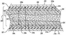
케이스(300)의 길이는, 제1 단부(302)와 제2 단부(304) 사이에서 연장될 수 있을 것이다. 제1 단부(302)는, 밑창 구조물(200)의 뒤꿈치 부분(16) 근처에 배치될 수 있으며, 그리고 제2 단부(304)는, 밑창 구조물(200)의 전족 부분(12) 근처에 배치될 수 있을 것이다. 케이스(300)는 또한, 밑창 구조물(200)의 종방향 축(L)에 실질적으로 수직으로 연장되는 두께, 및 바깥쪽 측부(18)와 안쪽 측부(20) 사이에서 연장되는 폭을 구비할 수 있을 것이다. 따라서, 케이스(300)의 길이, 폭 및 두께는, 내측 표면(214) 및 바닥 표면(222)에 의해 한정되는 캐비티(240)를 실질적으로 점유할 수 있으며, 그리고 바닥창(210)의 개별적으로 전족 부분, 중족 부분, 및 뒤꿈치 부분(12, 14, 16)을 통해 연장될 수 있을 것이다. 도 4에 도시된 바와 같이, 케이스(300)의 전체 두께는, 외부 표면(306)으로부터 연장되는 탄성중합체 재료(310)의 두께를 포함한다. 이러한 구성에서, 탄성중합체 재료(310)는, 중창(220)의 바닥 표면(222) 및 바닥창(210)의 내측 표면(214)과 대향하며, 그리고 그들과 접촉 상태에 놓인다.The length of the
도 3을 참조하면, 도 1의 3-3 선을 따라 취해진 단면도가, 입자형 소재(350)를 내포하며 그리고 바닥창(210)과 중창(220) 사이의 캐비티(240) 내부에 수용되는, 케이스(300)를 도시한다. 도 3은, 바닥창(210)의 내측 표면(214) 및 중창(220)의 바닥 표면(222)뿐만 아니라 측벽(230)의 내측 둘레 표면들과 대향하는, 외부 표면(306)(예를 들어, 외측 벽)을 구비하는 케이스(300)를 도시한다. 케이스(300)의 외부 표면(306)은, 신발류(10)의 사용 도중에 발을 위한 완충을 제공하기 위해 그 내부에 입자형 소재(350)를 수용하는, 내부 공동(308)을 한정할 수 있을 것이다. 더불어, 케이스(300)의 외부 표면(306)에 코팅되고 부착되는 탄성중합체 재료(310)는, 탄성중합체 재료(310)가 경화될 때 케이스(300)를 에워싸는 가요성 외측 피복을 제공한다. 일부 예에서, 탄성중합체 재료(310)는, 케이스(300)의 형성 도중에 경화된다. 마모-저항성 및 내구성과 같은 특성들을 부과함에 의해 케이스(300)를 보호하는 것에 부가하여, 탄성중합체 재료(310)는, 성형 프로세스 도중에 탄성중합체 재료(310)가 경화될 때 케이스(300)가 자체의 요구되는 형상을 취하는 것을 허용할 수 있을 것이다. 일부 구성에서, 중창(220), 또는 그의 일부가, 발의 바닥 표면과, 외부 표면(306) 및/또는 케이스(300)에 부착되는 경화된 탄성중합체 재료(310) 사이의 직접적인 접촉을 제공하기 위해 제거될 수 있을 것이다. 이러한 구성들에서, 케이스(300)는, 캐비티(240) 내에 상주하는 입자형 소재(350)가 밑창 구조물(200)의 점진적인 하중 작용 도중에 발의 바닥 표면과 합치하는 것을 허용하는, 가요성 판상물에 상응할 수 있을 것이다.Referring to FIG. 3, a cross-sectional view taken along the line 3-3 of FIG. 1 includes a
일부 시나리오에서, 액체로서 케이스(300)에 도포되는 탄성중합체 재료(310)의 적어도 일부분이, 내부 공동(308) 내로 그리고, 내부 공동(308)의 외측 영역들 근처에 상주하거나 또는 달리 케이스(300)의 외부 표면(306)에 실질적으로 인접하게 배치되는, 입자형 소재(350)의 부분들과 접촉 상태로 연장될 수 있을 것이다. 도 4의 내부 공동(308) 내부의 음영처리된 부분들은, 탄성중합체 재료(310)가 액체 상태에서 외부 표면(306)에 도포될 때 외부 표면(306)에 형성되는 개구들(309)을 통해 내부 공동(308) 내부에 수용되는, 탄성중합체 재료(310)를 표시한다. 예를 들어, 탄성중합체 재료(310)는, 개구들(309)을 통해 케이스(300) 내로 스며들 수 있으며 그리고 인접한 입자형 소재(350) 사이에 상주할 수 있고, 그로 인해 탄성중합체 재료(310)가 경화될 때 개구들(309) 근처에서 입자형 소재(350)를 함께 접합한다.In some scenarios, at least a portion of the
도 4를 참조하면, 도 3의 쇄선 박스(4) 내부의 상세 개략도가, 내부 공동(308) 내로 부분적으로 연장되는 탄성중합체 재료(310)를 도시한다. 탄성중합체 재료(310)는 단지, 내부 공동(308) 내부에 배치되는 입자형 소재(350)의 일부분과만 접촉하며, 그로 인해 탄성중합체 재료(310)에 노출되지 않는 내부 공동(308)의 (즉, 외부 표면(306)으로부터 분리되는) 내부 영역들 내부에 배치되는 입자형 소재(350)를 남긴다. 따라서, 탄성중합체 재료(310)에 노출되지도 탄성중합체 재료(310)와 접촉하지도 않는 제1 양(352)의 입자형 소재(350)가, 케이스(300)에 대해 이동하는 것이 허용된다. 역으로, 탄성중합체 재료(310)와 접촉 상태에 놓이는 제2 양(354)의 입자형 소재(350)는, 실질적으로 탄성중합체 재료(310)에 접착되고, 그로 인해 제2 양(354)의 입자형 소재(350)를 케이스(300)에 부착하고 고착시킨다. 따라서, 케이스(300)에 가요성 외측 피복을 제공하기 위해 케이스(300)를 에워싸는 것에 부가하여, 탄성중합체 재료(310)는, 제2 양(354)의 입자형 소재(350)에 접착될 수 있으며, 그리고 그에 따라, 제2 양(354)의 입자형 소재(350)가 반복되는 압축 도중에 밑창 구조물(200)의 캐비티(240) 전체에 걸쳐 이주하는 것을 방지하기 위해, 제2 양(354)의 입자형 소재(350)를 케이스(300)에 부착할 수 있을 것이다. 제1 양(352)의 입자형 소재(350)는, 케이스(300)에 대해 이동하는 것이 허용되며, 따라서, 소정 레벨의 소프트형 완충이, 밑창 구조물(200)에 가해지게 되는 지면 반력의 방향 및 크기에 기초하여 동적으로 분산될 수 있을 것이다.Referring to FIG. 4, a detailed schematic view inside the dashed
일부 구현예에서, 입자형 소재(350)(예를 들어, 발포체 구슬들)는, 입자형 소재(350)가 외부 표면(306)에 의해 에워싸이는 내부 공동들을 실질적으로 점유하는 것을 허용하도록, 케이스(300)를 약간 과하게 채우고, 그로 인해 자체의 요구되는 형상으로 형성되기 이전에, 외부 표면(306)에서 실질적으로 균일하고 부드러운 표면을 제공하기 위해 케이스(300)를 팽창시키도록 한다. 대조적으로, 케이스(300)가, 중력 만을 사용하여 채워질 때 (즉, 과하게 채워지지 않을 때), 형성된 케이스(300)는, 입자형 소재(350)에 의해 점유되지 않는 공동들을 구비할 수 있으며, 그로 인해 밑창 구조물(200)이 압축될 때 그 내부에 상주하는 입자형 소재(350)가 자유롭게 이동하고 이주할 충분한 기회를 제공하도록 한다. 일부 구성에서, (즉, 성형에 의해) 요구되는 형상으로 케이스(300)를 형성하는 것은, 탄성중합체 재료(310)에 부착되는 제2 양(354)의 입자형 소재(350)가, 제1 양(352)의 입자형 소재(350)보다 더욱 조밀하거나 또는 긴밀하게 패킹되도록 야기한다. 말하자면, 더욱 느슨하게 패킹된 제1 양(352)의 입자형 소재(350)는, 케이스(300)에 고착되는 제2 양(354)의 입자형 소재(350)가 밑창 구조물(200)이 압축될 때 더욱 응답형 완충을 제공할 수 있는 가운데, 지면-접촉 표면(212)이 지표면과의 맞물림을 위해 구를 때, 밑창 구조물(200)의 점진적인 하중 작용 도중에 어느 정도의 유동성 완충을 제공할 수 있을 것이다. 제1 양(352)의 입자형 소재(350)가 더욱 느슨하게 패킹될 수 있는 가운데, 제1 양(352)의 입자형 소재(350) 및 제2 양(354)의 입자형 소재(350)는, 여전히 케이스(300)에 의해 에워싸이는 모든 공동들을 실질적으로 채울 수 있을 것이다. 입자형 소재(350)가 케이스(300)의 모든 공동을 실질적으로 채우는 것으로 설명되지만, 입자형 소재(350)가 실질적으로 구형 형상을 구비함에 따라, 간극들이, 인접한 입자형 소재(350) 사이에 명백하게 존재한다는 것을 알아야 한다. 탄성중합체 재료(310)는 또한, 일정 정도의 응답형 완충을 제공할 수 있을 것이다.In some embodiments, the particulate material 350 (eg, foam beads) allows the
도 5 내지 도 8은, 갑피(100) 및 갑피(100)에 부착되는 밑창 구조물(200a)을 포함하는 신발류 물품(10a)을 제공한다. 신발류 물품(10a)에 대한 신발류 물품(10)과 연관되는 구성요소들의 구조 및 기능에 관한 실질적인 유사성의 관점에서, 유사한 참조 부호들이, 유사한 구성요소들을 식별하기 위해 이하에서 그리고 도면에서, 문자 확장자를 포함하는 유사한 참조 부호가 수정된 그러한 구성요소들을 식별하기 위해 사용되는 가운데, 사용된다.5 to 8 provide an article of
밑창 구조물(200a)은, 적층 구성으로 배열되는 바닥창(210a) 및 중창(220a)(예를 들어, 발 받침부(220a)로 또한 지칭됨)을 포함할 수 있을 것이다. 측벽(230)은, 바닥창(210a)의 둘레를 둘러쌀 수 있으며 그리고 바닥창(210a)과 중창(220a)을 그들 사이에 캐비티(240a)를 한정하기 위해 분리할 수 있을 것이다. 바닥창(210a)은, 바닥창(210a)의 지면-접촉 표면(212) 반대편 측부 상에 배치되는 내측 표면(214a)을 포함한다. 중창(220a)은, 중창(220a)의 발 받침부(224) 반대편 측부 상에 배치되는 바닥 표면(222a)을 포함한다. 바닥 표면(222a)은 내측 표면(214a)에 대향하며 그리고 측벽(230)은, 캐비티(240a)의 깊이를 한정하기 위해 바닥 표면(222a)과 내측 표면(214a)을 분리할 수 있을 것이다.
일부 구성에서, 캐비티(240a)는, 완충 재료(500)에 의해 에워싸이며 그리고 입자형 소재(350)를 내포하는 케이스(300a)를 포함하는, 완충 부재(400)를 수용한다. 도 6은, 제1 단부(402)와 제2 단부(404) 사이에서 종방향 축(L)을 따라 연장되는 길이를 갖는 완충 부재(400)를 도시하는, 신발류 물품(10a)의 분해도를 제공한다. 완충 부재(400)는, 중창(220a)의 바닥 표면(222a) 뿐만 아니라 바닥창(210a)의 내측 표면(214a)의 윤곽에 합치하는 윤곽들을 제공하도록 형성될 수 있을 것이다. 케이스(300a)를 에워싸는 완충 재료(500)는, 완충 부재(400)의 길이와 실질적으로 동등한 길이를 한정할 수 있을 것이다. 다른 구성에서, 완충 재료(500)는, 단지 바닥창(210a)의 내측 표면(214a) 또는 중창(220a)의 바닥 표면(222a)에 대향하는 케이스(300a)의 표면만이 완충 재료(500)에 의해 에워싸이도록, 케이스(300a)를 부분적으로 에워쌀 수 있을 것이다. 예를 들어, 완충 재료(500)는, 단지 내측 표면(214a)에 대향하며 그리고 내측 표면(214a)과 접촉하는 케이스(300a)의 영역에서 케이스(300a)에 적용될 수 있을 것이다. 이 점에 있어서, 케이스(300a)의 외부 표면(306a)이, 중창(220a)이 부분적으로 또는 전체적으로 제거되는 경우, 노출될 수 있으며 그리고 발 수용 표면을 형성할 수 있을 것이다. 중창(220a)은, 충분한 유연성을 갖는 중창(220a)을 제공하도록 도 1 내지 도 4의 중창(220)을 형성하는 가요성 재료로 형성될 수 있으며, 그로 인해 케이스(300a) 내부에 수용되며 그리고 캐비티(240a) 내에 상주하는 입자형 소재(350)가, 밑창 구조물(200a)의 점진적인 하중 작용 도중에 발의 바닥 표면의 윤곽과 상호작용하는 것을 허용한다.In some configurations, the
완충 재료(500)는, 지면-반력을 감쇠시키기 위해 가해지는 하중 하에서 탄력적 압축성을 제공하도록, 에틸-비닐-아세테이트 또는 폴리우레탄과 같은, 하나 이상의 중합체 발포체 재료로 형성될 수 있을 것이다. 역으로, 입자형 소재(350)에 의한 압축성이, 소프트형 완충을 제공할 수 있을 것이다. 따라서, 케이스(300a)를 에워싸는 완충 재료(500) 및 케이스(300a) 내부에 배치되는 입자형 소재(350)는, 가해지는 하중이 변화함에 따라 변화하는, 신발류 물품(10a)에 대한 점진적인 완충을 제공하기 위해 협력할 수 있을 것이다(즉, 하중이 더 커지면, 완충 재료(500)는 더 많이 압축되며, 그리고 그에 따라 신발류(10a)는 더 응답형으로 실행함).The
케이스(300a)는, 가요성 및 다공성 재료로 형성될 수 있을 것이다. 예를 들어, 케이스(300a)는, 도 1 내지 도 4의 케이스(300)를 형성하는, 메시 재료 및/또는 나일론 재료로 형성될 수 있을 것이다. 도 1 내지 도 4에 대해 이상에 설명된 것과 유사한 방식으로, 탄성중합체 재료(310)는, 케이스(300a)를 에워싸는 가요성 외측 피복을 케이스(300a)에 제공하기 위해, 케이스(300a)의 표면들에 도포될 수 있을 것이다. 부가적으로 또는 대안적으로, 완충 재료(500)는, 완충 부재(400)가 바닥창(210a)의 내측 표면(214a) 및 중창(220a)의 바닥 표면(222a)의 표면 윤곽들에 합치하도록 성형될 때(예를 들어, 도 21 내지 도 24), 탄성중합체 재료(310)에 접착하는 것에 의해 케이스(300a)를 에워쌀 수 있을 것이다. 일부 예에서, 완충 재료(500), 입자형 소재(350), 및 탄성중합체 재료(310)는, 하나 이상의 재생 가능한 중합체로 형성된다.The
도 7을 참조하면, 신발류 물품(10a)의 완충 부재(400)에 대한 평면도가, 탄성중합체 재료(310)로 코팅되며 그리고 입자형 소재(350)를 내포하는 케이스(300a)를 에워싸는 완충 재료(500)를 도시한다. 케이스(300a)는, 형성된 완충 부재(400)의 완충 재료(500)가 탄성중합체 재료(310)로 코팅되는 케이스(300a)를 에워쌀 때, 그 내부에 상주하는 입자형 소재(350)를 밑창 구조물(200a)의 지정된 위치들에 배치하기 위해 선택되는, 크기 및 형상을 구비할 수 있을 것이다. 예를 들어, 케이스(300a)는 (완충 재료(500)에 의해 에워싸일 때), 밑창 구조물(200a)의 뒤꿈치 부분(16)과 전족 부분(12) 사이에, 입자형 소재(350)가 그들 사이에서 이주하는 것을 방지하는, 부분적 장벽을 제공하기 위해 좁아질 수 있을 것이다. 부가적으로 또는 대안적으로, 케이스(300a)의 벽들은, 각각 개별적인 부분의 입자형 소재(350)를, 입자형 소재(350)의 부분들이 인접한 세그먼트들 사이에서 이주하는 것을 방지하도록, 내포하는, 적어도 2개의 세그먼트를 한정하기 위해 함께 고정될 수 있을 것이다. 케이스(300a)의 벽들은, 예를 들어 뒤꿈치 부분(16)과 전족 부분(12) 사이에 배치되는 영역(R)에서 합쳐질 수 있다. 일부 예에서, 케이스(300a)는, 뒤꿈치 부분(16)에 상주하는 입자형 소재(350)의 양과 비교하여, 더 많은 양의 입자형 소재(350)가 집합적으로 전족 부분(12) 및 중족 부분(14)에 상주하도록, 성형된다. 따라서, 전족 부분(12) 및 중족 부분(14)과 연관되는 케이스(300a)의 부분들은, 뒤꿈치 부분(16)보다, 바깥쪽 측부(18)와 안쪽 측부(20) 사이에서 연장되는 더 큰 폭을 한정하는, 밑창 구조물(200a)의 전족 부분(12) 및 중족 부분(14)으로 인해, 입자형 소재(350)를 내포하기 위한 더 큰 용적을 한정할 수 있을 것이다. 도 8은, 바닥창(210a)과 중창(220a) 사이의 캐비티(240a) 내부에 수용되는 완충 부재(400)를 도시하는, 도 5의 8-8 선을 따라 취해진 부분 단면도를 제공한다. 완충 재료(500)는, 바닥창(210a)의 내측 표면(214a)과 접촉 상태에 놓이는 바닥 부분(501) 및, 완충 재료(500)의 바닥 부분(501) 반대편 측부 상에 배치되며 그리고 중창(220a)의 바닥 표면(222a)과 접촉 상태에 놓이는 상부 부분(502)을 포함한다.Referring to FIG. 7, a plan view of the cushioning
일부 구현예에서, 케이스(300a)는, 완충 재료(500)의 바닥 부분(501) 및 상부 부분(502) 사이에 에워싸이게 된다. 케이스(300a)의 외부 표면(306a)은, 신발류(10a)의 사용 도중에 발을 위한 완충을 제공하기 위해 그 내부에 상주하는 입자형 소재(350)를 수용하는, 내부 공동(308a)을 한정할 수 있을 것이다. 탄성중합체 재료(310)는, 도 1 내지 도 4를 참조하여 이상에 설명된 것과 유사한 방식으로, 액체로서 케이스(300a)의 외부 표면(306a) 상에 코팅될 수 있을 것이다. 따라서, 탄성중합체 재료(310)는, 완충 부재(400)가 성형될 때(예를 들어, 도 21 내지 도 23) 완충 재료(500)가 케이스(300a)를 에워싸는 것을 허용하도록, 케이스(300a)의 외부 표면(306a)에 그리고 완충 재료(500)의 바닥 부분(501) 및 상부 부분(502)에 접착될 수 있을 것이다. 일부 예에서, 완충 부재(400)를 성형하기 이전에, 바닥 부분(501)은 제1 층에 대응할 수 있으며, 그리고 상부 부분(502)은, 제1 층과 분리된 제2 층에 대응할 수 있을 것이다. 이러한 예들에서, 제1 층(501) 및 제2 층(502)은, 케이스(300a)를 에워싸는 완충 재료(500)를 형성하기 위해 탄성중합체 재료(310)에 접착될 수 있을 것이다. 다른 구현예에서, 케이스(300a)는, 완충 재료(500)의 바닥 부분(501) 또는 상부 부분(502) 중의 하나에 의해 부분적으로 에워싸이게 된다.In some embodiments,
도 1 내지 도 4의 케이스(300)와 마찬가지로, 케이스(300a)의 외부 표면(306a) 상에 코팅되는 탄성중합체 재료(310)의 적어도 일부분이, 개구들(309)을 통해 내부 공동(308a) 내로 그리고, 내부 공동(308a)의 외측 영역들 근처에 상주하거나 또는 달리 케이스(300a)의 외부 표면들(306a)에 실질적으로 인접하게 배치되는, 입자형 소재(350)의 부분들과 접촉 상태로 연장될 수 있을 것이다. 내부 공동(308a) 내부의 음영처리된 부분들은, 내부 공동(308a) 내부에 배치되는, 탄성중합체 재료(310)의 일부분을 표시한다. 그에 따라, 도 8의 도면은, 탄성중합체 재료(310)로부터 이격되는 제1 양(352)의 입자형 소재(350)를 에워싸며 그리고 또한 탄성중합체 재료(310)와 접촉 상태에 놓이는 제2 양(354)의 입자형 소재(350)를 에워싸는, 내부 공동(308a)을 도시한다. 따라서, 제2 양(354)의 입자형 소재(350)는, 제1 양(352)의 입자형 소재(350)는 케이스(300a) 및 완충 재료(500)에 대해 이동하도록 허용되는 가운데, 탄성중합체 재료에 접착함에 의해 케이스(300a)에 부착 또는 고착될 수 있을 것이다. 유리하게, 제2 양(354)의 입자형 소재(350)는, 반복되는 압축 도중에 밑창 구조물(200a)의 캐비티(240a) 전체에 걸쳐 이주하는 것이 방지되는 가운데, 제1 양(352)의 입자형 소재(350)는, 케이스(300a)에 대해 (그리고 또한 제2 양(354)의 입자형 소재(350)에 대해) 이동하는 것이 허용되며, 따라서 소정 레벨의 소프트형 완충이, 밑창 구조물(200a)에 가해지게 되는 지면 반력의 방향 및 크기에 기초하여 동적으로 분산될 수 있을 것이다.Similar to the
완충 재료(500)는, 밑창 구조물(200a)의 점진적인 하중 작용 도중에 중창(220a)과 바닥창(210a) 사이에서 압축될 수 있을 것이다. 이상에 설명된 바와 같이, 입자형 소재(350)에 의한 압축성은, 소정 레벨의 소프트형 완충을 제공할 수 있는 가운데, 완충 재료(500)에 의한 압축성은, 응답형 완충을 제공할 수 있을 것이다. 따라서, 밑창 구조물(200a)이 하중 하에 놓일 때, 입자형 소재(350)가, 지면-반력의 초기 충격 도중에 소정 레벨의 소프트형 완충을 제공할 수 있는 가운데, 완충 재료(500)의 압축이, 초기 충격 이후에, 응답형 완충을 제공하기 위해 일어날 수 있을 것이다. 따라서, 완충 재료(500) 및 입자형 소재(350)는, 가해지는 하중이 변화함에 따라 변화하는, 신발류 물품(10a)의 점진적인 완충을 제공하기 위해 협력할 수 있을 것이다(즉, 하중이 더 커지면, 완충 재료(500)는 더 많이 압축되며, 그리고 그에 따라 신발류(10a)는 더 응답형으로 실행함). 일부 구성에서, 중창(220a), 또는 그의 일부가, 발의 바닥 표면과 완충 부재(400) 사이의 직접적인 접촉을 제공하기 위해 제거될 수 있을 것이다. 이러한 구성들에서, 완충 부재(400)는, 케이스(300a) 내에 상주하는 입자형 소재(350) 및 케이스(300a)를 에워싸는 완충 재료(500)가 밑창 구조물(200a)의 점진적인 하중 작용 도중에 발의 바닥 표면과 합치하는 것을 허용하는, 가요성 판상물에 상응할 수 있을 것이다. 추가로, 완충 부재(400)는, 밑창 구조물(200a)에 부착되거나 또는 부착되지 않을 수 있는, 소위 "삽입식(drop-in)" 완충 부재(400)일 수 있을 것이다. 말하자면, 완충 부재(400)는, 갑피(100)의 내부 공동(102)에서 신발류 물품(10a) 내로 삽입될 수 있으며, 그리고 내측 표면(214a) 상에 놓일 수 있을 것이다. 완충 부재(400)는, 내측 표면(214a) 상에 놓일 수 있으며, 또는 대안적으로, 적당한 접착제를 통해 내측 표면(214a)에 접착될 수 있을 것이다.The
도 9 내지 도 11을 참조하면, 신발류 물품(10b)이, 제공되며 그리고, 갑피(100) 및 갑피(100)에 부착되는 밑창 구조물(200b)을 포함한다. 신발류 물품(10b)에 대한 신발류 물품(10)과 연관되는 구성요소들의 구조 및 기능에 관한 실질적인 유사성의 관점에서, 유사한 참조 부호들이, 유사한 구성요소들을 식별하기 위해 이하에서 그리고 도면에서, 문자 확장자를 포함하는 유사한 참조 부호가 수정된 그러한 구성요소들을 식별하기 위해 사용되는 가운데, 사용된다.9 to 11, an article of
밑창 구조물(200b)은, 적층 구성으로 배열되는 바닥창(210b) 및 중창(220b)을 포함할 수 있을 것이다. 측벽(230)은, 바닥창(210b)의 둘레를 둘러쌀 수 있으며 그리고 바닥창(210b)과 중창(220b)을 그들 사이에 캐비티(240b)를 한정하기 위해 분리할 수 있을 것이다. 바닥창(210b)은, 바닥창(210b)의 지면-접촉 표면(212) 반대편 측부 상에 배치되는 내측 표면(214b)을 포함한다. 중창(220b)은, 중창(220b)의 발 받침부(224) 반대편 측부 상에 배치되는 바닥 표면(222b)을 포함한다. 바닥 표면(222b)은 내측 표면(214b)에 대향하며 그리고 측벽(230)은, 캐비티(240b)의 깊이를 한정하기 위해 바닥 표면(222b)과 내측 표면(214b)을 분리할 수 있을 것이다.The
일부 구성에서, 캐비티(240b)는, 신발류(10b)의 사용 도중에 발을 위한 완충을 제공하기 위한 입자형 소재(350)를 내포하는, 케이스(300b)를 수용한다. 케이스(300b)는, 밑창 구조물(200b)의 종방향 축(L)에 실질적으로 평행하게 연장되는 길이를 한정할 수 있으며, 그리고 바닥창(210b)의 내측 표면(214b) 및 중창(220b)의 바닥 표면(222b)의 표면 윤곽들에 합치하는 윤곽들을 제공하도록 형성될 수 있을 것이다. 도 1 내지 도 4의 신발류 물품(10)의 케이스(300)와 마찬가지로, 케이스(300b)는, 메시 재료 및/또는 나일론 재료와 같은 하나 이상의 가요성 및 다공성 재료로 형성될 수 있으며, 그리고 케이스(300b)를 에워싸는 가요성 외측 피복을 제공하기 위해 탄성중합체 재료(310)로 코팅될 수 있을 것이다. 탄성중합체 재료(310)의 적어도 일부분은, 케이스(300b)의 외부 표면(306b)에 의해 한정되는 내부 공동(308b) 내로 연장될 수 있을 것이다. 따라서, 제1 양(352)의 입자형 소재(350)는 케이스(300b)에 대해 이동 가능할 수 있으며, 그리고 제2 양(354)의 입자형 소재(350)는, 탄성중합체 재료(310)에 접착되며 그리고 그에 따라 케이스(300b)에 대해 이동 가능하지 않다. 케이스(300)와 마찬가지로, 케이스(300b)는, 바닥창(210b)의 지면-접촉 표면(212)이 뒤꿈치 부분(16)과 전족 부분(12) 사이에서 지표면과의 맞물림을 위해 구를 때, 점진적인 완충을 제공한다. 제2 양(354)의 입자형 소재(350) 및 탄성중합체 재료(310)는, 도 1 내지 도 4의 신발류 물품(10)을 참조하여 이상에 설명된 것과 유사한 방식으로 상호작용한다.In some configurations, the
일부 구현예에서, 하나 이상의 제1 발포체 세그먼트(362)가, 탄성중합체 재료(310)에 부착되며, 그리고 케이스(300b)의 외부 표면(306b) 상에 배치된다. 도 10은, 캐비티(240b) 내부에 수용되는 케이스(300b) 및, 케이스(300b)의 외부 표면(306b) 상에 배치되는 탄성중합체 재료(310)에 접착함에 의해, 케이스(300b)에 부착되는 제1 발포체 세그먼트들(362)을 도시하는 신발류 물품(10b)의 분해도를 제공한다. 탄성중합체 재료(310)는, 도 1 내지 도 4에 대해 이상에 설명된 것과 유사한 방식으로, 액체 상태에서 케이스(300b)의 외부 표면(306b) 상에 코팅될 수 있을 것이다. 그에 따라, 탄성중합체 재료(310)가 경화될 때, 케이스(300b)가 중창(220b)의 바닥 표면(222b) 및 바닥창(210b)의 내측 표면(214b)의 표면 윤곽들에 합치하는 윤곽들을 제공하도록 형성될 때, 탄성중합체 재료(310)는, 케이스(300b)의 외부 표면(306b)에 그리고 또한 제1 발포체 세그먼트들(362)에 접착될 수 있을 것이다. 일부 예에서, 제1 발포체 세그먼트들(362)은, 케이스(300b)가 밑창 구조물(200b)의 상기한 표면 윤곽들에 합치하도록 성형될 때(예를 들어, 도 24 내지 도 26), 탄성중합체 재료(310)에 부착된다.In some embodiments, one or more
일부 구성에서, 소정량의 제2 발포체 세그먼트들(364)이, 케이스(300b)의 내부 공동(308b) 내부에 배치된다. 도 11을 참조하면, 도 9의 11-11선을 따라 취해진 부분 단면도가, 바닥창(210b)과 중창(220b) 사이의 캐비티(240b) 내부에 수용되는 케이스(300b), 케이스(300b)의 외부 표면(306b)에 부착되는 제1 발포체 세그먼트들(362), 및 내부 공동(308b) 내부에 배치되는 소정량의 제2 발포체 세그먼트들(364)을 도시한다. 제1 발포체 세그먼트들(362)은, 케이스(300b)와 중창(220b)의 바닥 표면(222b) 사이에서 그리고 또한 케이스(300b)와 바닥창(210b)의 내측 표면(214b)의 사이에서, 밑창 구조물(200b)의 길이를 따라 서로로부터 이격될 수 있을 것이다. 예를 들어, 제1 발포체 세그먼트들(362) 중의 2개가, 케이스(300b)와 중창(220b)의 바닥 표면(222b) 사이에서, 밑창 구조물(200b)의 전족 부분(12) 및 뒤꿈치 부분(16) 중의 개별적인 것들에 배치될 수 있을 것이다. 부가적으로 또는 대안적으로, 제1 발포체 세그먼트들(362) 중의 3개가, 케이스(300b)와 바닥창(210b)의 내측 표면(214b) 사이에서, 밑창 구조물(200b)의 전족 부분(12), 중족 부분(14), 및 뒤꿈치 부분(16) 중의 개별적인 것들에 배치될 수 있을 것이다. 다른 구성에서, 더 많은 또는 더 적은 제1 발포체 세그먼트들(362)이, 케이스(300b)와 바닥 표면(222b) 사이 및/또는 케이스(300b)와 내측 표면(214b) 사이에 배치될 수 있을 것이다. 제1 발포체 세그먼트들(362)은, 밑창 구조물(200b)이 가해지는 하중 하에 놓일 때 지면 반력을 감쇠시키기 위한 압축성을 탄력적으로 제공하며 그리고 발포체 재료로 형성되는 것으로 제한되지 않는, 탄력 부재들에 상응할 수 있을 것이다. 예를 들어, 세그먼트들(362) 중의 어느 하나 또는 모두가, 유체 충전 주머니일 수 있다. 일부 구성에서, 입자형 소재(350), 탄성중합체 재료(310), 제1 발포체 세그먼트들(362), 및 제2 발포체 세그먼트들(364)은, 하나 이상의 재생 가능한 중합체 재료로 형성된다.In some configurations, a predetermined amount of
소정량의 제2 발포체 세그먼트들(364) 및 입자형 소재(350)는, 내부 공동(308b) 내부에 배치될 수 있을 것이다. 여기서, 제2 발포체 세그먼트들(364)은, 입자형 소재(350)(예를 들어, 발포체 구슬들)와 상이한 크기 및 형상을 구비할 수 있을 것이다. 일부 예에서, 제2 발포체 세그먼트들(364)은, 발포체 구슬들보다 더 크며, 그리고 압축될 때 더욱 응답형인 완충 특성을 보인다. 일부 예에서, 제2 발포체 세그먼트들(364)의 적어도 일부분은, 내부 공동(308b) 내부에 배치되는 탄성중합체 재료(310)에 의해 케이스(300b)에 부착된다. 더욱 구체적으로, 탄성중합체 재료(310)와 접촉하는 제2 발포체 세그먼트들(364)의 부분들은, 제2 양(354)의 입자형 소재(350)와 유사한 방식으로 탄성중합체 재료(310)에 접착함에 의해, 케이스(300b)에 부착된다. 그에 따라, 제2 발포체 세그먼트들(364)의 이러한 부분들은, 제2 양(354)의 입자형 소재(350)와 함께 케이스(300b)에 부착될 수 있을 것이다.The predetermined amount of
제1 양(352)의 입자형 소재(350)와 마찬가지로, 제2 발포체 세그먼트들(364)의 적어도 일부분은, 케이스(300b)에 대해 이동 가능하다. 말하자면, 탄성중합체 재료(310)로부터 이격되는 제2 발포체 세그먼트들(364)의 부분들은, 밑창 구조물(200b)에 가해지는 지면 반력의 방향 및 크기에 응답하여 유동적 완충 특성을 제공하기 위해, 제1 양(352)의 입자형 소재(350)와 함께, 케이스(300b)에 대해 이주 및 이동하도록 허용된다. 이상에 설명된 바와 같이, 제1 발포체 세그먼트들(362) 및 제2 발포체 세그먼트들(364)은, 입자형 소재(350)보다 더욱 탄력적이며, 그리고 그에 따라 더욱 응답형이다. 따라서, 발포체 세그먼트들(362, 364)이 압축될 때, 이들은, 압축될 때 입자형 소재(350)에 의해 제공되는 소프트형 완충의 레벨과 비교할 때, 더욱 응답형의 느낌을 제공한다. 따라서, 제1 발포체 세그먼트들(362) 및 제2 발포체 세그먼트들(364)은, 통상적인 중창이 제공하는 기능성을 향상시키기 위해 그리고 완충 특성들을 향상시키기 위해, 입자형 소재(350)와 협력할 수 있을 것이다. 예를 들어, 밑창 구조물(200b)이 하중 하에 놓일 때, 입자형 소재(350) 압축이, 지면-반력의 초기 충격 도중에 소정 레벨의 소프트형 완충을 제공할 수 있는 가운데, 제1 발포체 세그먼트들(362) 및 제2 발포체 세그먼트들(364)의 압축이, 초기 충격 이후에, 응답형 완충을 제공하기 위해 일어날 수 있을 것이다. 그에 따라, 캐비티(240b) 내에 상주하는 입자형 소재(350) 및 발포체 세그먼트들(362, 364)은, 가해지는 하중이 변화함에 따라 변화하는, 신발류 물품(10b)에 대한 점진적인 완충을 제공하기 위해 협력할 수 있을 것이다(즉, 하중이 더 커지면, 발포체 세그먼트들(362, 364)은 더 많이 압축되며, 그리고 그에 따라 신발류(10b)는 더 응답형으로 실행함).Similar to the
중창(220b)은, 충분한 유연성을 갖는 중창(220b)을 제공하도록 도 1 내지 도 4의 중창(220)을 형성하는 가요성 재료로 형성될 수 있으며, 그로 인해 케이스(300b) 내부에 수용되는 입자형 소재(350), 제2 발포체 세그먼트들(364), 그리고 케이스(300b)의 외부 표면(306b) 상에 배치되는 제1 발포체 세그먼트들(362)이, 밑창 구조물(200b)의 점진적인 하중 작용 도중에 발의 바닥 표면의 윤곽과 상호작용하는 것을 허용한다. 일부 구성에서, 중창(220), 또는 그의 일부가, 발의 바닥 표면과, 케이스(300b)의 외부 표면(306b) 및/또는 케이스(300b)의 외부 표면(306b) 상에 배치되는 제1 발포체 세그먼트들(362) 사이의 직접적인 접촉을 제공하기 위해 제거될 수 있을 것이다. 이러한 구성들에서, 케이스(300b)는, 캐비티(240b) 내에 상주하는 입자형 소재(350)가 밑창 구조물(200b)의 점진적인 하중 작용 도중에 발의 바닥 표면과 합치하는 것을 허용하는, 가요성 판상물에 상응할 수 있을 것이다.The
도 12 내지 도 14를 참조하면, 신발류 물품(10c)이, 제공되며 그리고, 갑피(100) 및 갑피(100)에 부착되는 밑창 구조물(200c)을 포함한다. 신발류 물품(10c)에 대한 신발류 물품(10)과 연관되는 구성요소들의 구조 및 기능에 관한 실질적인 유사성의 관점에서, 유사한 참조 부호들이, 유사한 구성요소들을 식별하기 위해 이하에서 그리고 도면에서, 문자 확장자를 포함하는 유사한 참조 부호가 수정된 그러한 구성요소들을 식별하기 위해 사용되는 가운데, 사용된다.12 to 14, an article of
밑창 구조물(200c)은, 적층 구성으로 배열되는 바닥창(210c) 및 중창(220c)을 포함할 수 있을 것이다. 측벽(230)은, 바닥창(210c)의 둘레를 둘러쌀 수 있으며 그리고 바닥창(210c)과 중창(220c)을 그들 사이에 캐비티(240c)를 한정하기 위해 분리할 수 있을 것이다. 바닥창(210c)은, 바닥창(210c)의 지면-접촉 표면(212) 반대편 측부 상에 배치되는 내측 표면(214c)을 포함한다. 중창(220c)은, 중창(220c)의 발 받침부(224) 반대편 측부 상에 배치되는 바닥 표면(222c)을 포함한다. 바닥 표면(222c)은 내측 표면(214c)에 대향하며 그리고 측벽(230)은, 캐비티(240c)의 깊이를 한정하기 위해 바닥 표면(222c)과 내측 표면(214c)을 분리할 수 있을 것이다.The
일부 구성에서, 캐비티(240c)는, 신발류(10c)의 사용 도중에 발을 위한 완충을 제공하기 위한 입자형 소재(350)를 내포하는, 케이스(300c)를 수용한다. 케이스(300c)는, 제1 단부(302)와 제2 단부 사이에서 밑창 구조물(200c)의 종방향 축(L)에 실질적으로 평행한 방향으로 연장되는 길이를 한정할 수 있을 것이다. 케이스(300c)는, 적어도 중창(220c)의 바닥 표면(222c)과 합치하는 윤곽을 제공하도록 형성될 수 있을 것이다. 도 1 내지 도 4의 신발류 물품(10)의 케이스(300)와 마찬가지로, 케이스(300c)는, 메시 재료 및/또는 나일론 재료와 같은 하나 이상의 가요성 및 다공성 재료로 형성될 수 있으며, 그리고 케이스(300c)를 에워싸거나 또는 적어도 케이스(300c)의 외부 표면(306c) 상에 배치되는 가요성 외측 피복을 제공하기 위해 탄성중합체 재료(310)로 코팅될 수 있을 것이다.In some configurations, the
탄성중합체 재료(310)의 적어도 일부분은, 케이스(300c)의 외부 표면(306c)에 의해 한정되는 내부 공동(308c) 내로 연장될 수 있을 것이다. 따라서, 제1 양(352)의 입자형 소재(350)는 케이스(300c)에 대해 이동 가능할 수 있으며, 그리고 탄성중합체 재료(310)에 접착되는 제2 양(354)의 입자형 소재(350)는, 케이스(300c)와 함께하는 이동을 위해 고정된다. 도 1 내지 도 4의 케이스(300)와 마찬가지로, 케이스(300c)는, 바닥창(210c)의 지면-접촉 표면(212)이 뒤꿈치 부분(16)과 전족 부분(12) 사이에서 지표면과의 맞물림을 위해 구를 때, 신발류(10c)를 위한 점진적인 완충을 제공한다. 제2 양(354)의 입자형 소재(350) 및 탄성중합체 재료(310)는, 도 1 내지 도 4의 신발류 물품(10)을 참조하여 이상에 설명된 것과 유사한 방식으로 상호작용할 수 있을 것이다. 중창(220c)은, 충분한 유연성을 갖는 중창(220c)을 제공하도록 도 1 내지 도 4의 중창(220)을 형성하는 가요성 재료로 형성될 수 있으며, 그로 인해 케이스(300c) 내부에 수용되며 그리고 캐비티(240c) 내에 상주하는 입자형 소재(350)가, 밑창 구조물(200c)의 점진적인 하중 작용 도중에 발의 바닥 표면의 윤곽과 상호작용하는 것을 허용한다.At least a portion of the
일부 구현예에서, 밑창 구조물(200c)은, 바닥창(210c)의 내측 표면(214c)과 케이스(300c) 사이의 캐비티(240c) 내부에 배치되는, 탄력 부재(600)를 포함한다. 도 13을 참조하면, 신발류 물품(10c)의 분해도가, 바닥창(210c)의 내측 표면(214c) 상에 배치되는 탄력 부재(600) 및 탄력 부재(600)와 중창(220c)의 바닥 표면(222c) 사이에 배치되는 입자형 소재(350)를 내포하는 케이스(300c)를 도시한다. 탄력 부재(600)는, 캐비티(240c) 내부의 빈 공간의 일부분을 점유하도록 크기 결정되고 성형될 수 있을 것이다. 여기서, 탄력 부재(600)와 바닥 표면(222c) 사이의 간극이, 케이스(300c)를 수용하는 캐비티(240c) 내부의 빈 공간의 나머지 부분을 한정한다. 따라서, 탄력 부재(600) 및 케이스(300)는, 캐비티(240c)에 의해 한정되는 빈 공간의 전체 용적을 실질적으로 점유할 수 있을 것이다. 일부 구성에서, 중창(220c), 또는 그의 일부가, 발의 바닥 표면과, 케이스(300c)의 외부 표면(306) 및/또는 케이스(300c)에 접착되는 경화된 탄성중합체 재료(310) 사이의 직접적인 접촉을 제공하기 위해 제거될 수 있을 것이다.In some implementations, the
탄력 부재(600)는, 중창(220c)과 바닥창(210c) 사이에서 탄력적으로 압축될 수 있을 것이다. 일부 구성에서, 탄력 부재(600)는, 중합체 발포체의 판상물에 상응한다. 다른 구성에서, 탄력 부재(600)는, 가압 유체를 수용하는 그리고 그 내부에 가압 유체를 구속하기 위한 내구성 있는 밀봉 장벽을 제공하는, 내부 공동을 한정하는 유체 충전 챔버에 상응한다. 가압 유체는, 공기일 수 있을 것이다. 넓은 범위의 중합체 재료들이, 유체 충전 챔버를 형성하기 위해 활용될 수 있을 것이다. 중합체 재료들을 선택함에 있어서, 인장 강도, 신장 특성들, 피로 특성들, 및 동적 계수들과 같은, 공학적 특성들뿐만 아니라, 챔버에 의해 수용되는 유체의 확산을 방지하는 재료들의 능력이, 고려될 수 있을 것이다. 유체 충전 챔버를 형성하기 위해 사용되는 예시적 재료들은, 열가소성 우레탄, 폴리우레탄, 폴리에스테르, 폴리에스테르 폴리우레탄, 및 폴리에테르 폴리우레탄 중의 하나 이상을 포함할 수 있을 것이다.The
밑창 구조물(200c)의 점진적인 하중 작용 도중에, 중창(220c)은, 케이스(300c) 내부의 입자형 소재(350)가 중창(220c)과 탄력 부재(600) 사이에서 압축됨에 따라, 바닥창(210c)을 향해 병진이동할 수 있을 것이다. 여기서, 탄력 부재(600)는, 바닥창(210c)과 중창(220c) 사이에서 탄력적으로 압축된다. 탄력 부재(600)는, 케이스(300c) 내부에 상주하는 소정량의 입자형 소재(350)(예를 들어, 발포체 구슬들)와 함께, 통상적인 중창이 제공하는 기능성 및 완충 특성을 향상시키기 위해, 협력할 수 있을 것이다. 예를 들어, 밑창 구조물(200c)이 하중 하에 놓일 때, 입자형 소재(350) 압축이, 지면-반력의 초기 충격 도중에 소정 레벨의 소프트형 완충을 제공할 수 있는 가운데, 탄력 부재(600)의 압축이, 초기 충격 이후에, 응답형 완충을 제공하기 위해 일어날 수 있을 것이다. 따라서, 캐비티(240c) 내에 상주하는, 탄력 부재(600) 및 케이스(300c) 내부에 배치되는 입자형 소재(350)는, 가해지는 하중이 변화함에 따라 변화하는, 신발류 물품(10c)에 대한 점진적인 완충을 제공하기 위해 협력할 수 있을 것이다(즉, 하중이 더 커지면, 탄력 부재(600)는 더 많이 압축되며, 그리고 그에 따라 신발류(10c)는 더 응답형으로 실행함).During the gradual load action of the
일부 구현예에서, 케이스(300c)는, 내부 공동(308) 내부에 배치되며 그리고 케이스(300c)의 벽들에 접합되는, 적어도 하나의 분할 벽(650)을 포함할 수 있을 것이다. 도 14는, 케이스(300c)의 위쪽 벽 부분(320)에 접합되는 제1 단부 및 케이스(300c)의 아래쪽 벽 부분(322)에 접합되는 제2 단부를 포함하는 분할 벽(650)을 도시하는, 도 13의 14-14 선을 따라 취해진 케이스(300c)의 단면도를 제공한다. 케이스(300c)가 캐비티(240c) 내부에 배치될 때, 위쪽 벽 부분(320)은 중창(220c)의 바닥 표면(222c)에 대향할 수 있으며, 그리고 아래쪽 벽 부분(322)은 탄력 부재(600)에 대향할 수 있을 것이다. 탄력 부재(600)가 생략되는 구성들에서, 아래쪽 벽 부분(322)은, 바닥창(210c)의 내측 표면(214c)에 대향하며 그리고 그에 접촉할 수 있을 것이다.In some implementations,
분할 벽(650)은, 제1 양(352)의 입자형 소재(350)의 일부분 및 제2 양(354)의 입자형 소재(350)의 일부분 중의 적어도 하나를 내포하는, 적어도 2개의 세그먼트(652, 654)를 한정할 수 있을 것이다. 일부 예에서, 각 세그먼트(652, 654)는, 밑창 구조물(200c)의 종방향 축(L)에 실질적으로 평행하게 연장되는 개별적인 채널에 상응한다. 일부 예에서, 분할 벽(650)은, 밑창 구조물(200c)의 종방향 축(L)에 실질적으로 수직이며 그리고 밑창 구조물(200c)의 전족 부분(12), 중족 부분(14), 및 뒤꿈치 부분(16)을 통해 케이스(300c)의 길이를 따라 연장된다. 다른 예에서, 분할 벽(650)은, 종방향 축(L)에 실질적으로 평행할 수 있으며, 또는 종방향 축(L)에 대해 경사질 수 있고 및/또는 케이스(300c)의 길이의 단지 일부분을 따라 연장될 수 있을 것이다. 일부 구성에서, 2개 이상의 분할 벽(650)이, 3개 이상의 세그먼트를 한정하기 위해 케이스(300c)의 벽들에 접합된다. 일부 구성에서, 분할 벽(650)은, 생략될 수 있으며, 그리고 위쪽 벽 부분(320) 및 아래쪽 벽 부분(322)이, 적어도 2개의 세그먼트(652, 654)를 한정하기 위해 함께 고정될 수 있을 것이다.The dividing
분할 벽(650) 및 세그먼트들(652, 654)은, 신발류(10c)의 사용 도중에, 발을 위한 완충을 제공할 뿐만 아니라, 각 세그먼트(652, 654) 내부에 상주하는 제1 양(352)의 입자형 소재(350)의 이주를 제어하기 위해, 협력할 수 있을 것이다. 일부 예에서, 분할 벽(650)은, 밑창 구조물의 점진적인 하중 작용 도중에 지면 반력을 감쇠시키기 위한 탄력적 압축성을 제공하기 위해, 하나 이상의 중합체 발포체 재료로 형성될 수 있을 것이다. 각 세그먼트(652, 654) 내에 상주하는 제1 양(352)의 입자형 소재(350)는, 각 세그먼트(652, 654) 내부에서 밑창 구조물(200c)의 종방향 축(L)에 실질적으로 평행한 방향으로 그리고 케이스(300c)에 부착되는 제2 양(354)의 입자형 소재(350) 사이에서, 이동하도록 허용될 수 있을 것이다. 역으로, 분할 벽(650)은, 세그먼트들(652, 654) 내부에 상주하는 제1 양(352)의 입자형 소재(350)가 세그먼트들(652, 654) 사이에서 이동하는 것을 제한할 수 있을 것이다.The
일부 구성에서, 분할 벽(650)은, 장력 하의 섬유들로 형성될 수 있는, 인장 부재를 포함한다. 예를 들어, 위쪽 벽 부분(320)에 접합되는 제1 단부를 아래쪽 벽 부분(322)에 접합되는 제2 단부로부터 분리하는 거리가, 적어도 하나의 분할 벽(650)을 형성하는 섬유들이 장력 하에 놓이도록 야기할 수 있을 것이다. 장력 하에 놓이는 동안, 섬유들은, 분할 벽(650)을 관통하는 공극들(미도시)을 한정할 수 있을 것이다. 일부 예에서, 제1 양(352)의 입자형 소재(350)는, 섬유들 중의 인접한 것들 사이의 공극들을 통해 세그먼트들(652, 654) 사이에서 이동한다. 역으로, 다른 예들에서, 공극들은, 제1 양(352)의 입자형 소재(350)의 통과를 허용하기에 충분할 정도로 크지 않을 수 있으며, 그로 인해 분할 벽(650)을 형성하는 섬유들이, 입자형 소재(350)가 세그먼트들(652, 654) 사이에서 자유롭게 이동하는 것을 제한하는 것을 허용한다. 부가적으로, 제1 양(352)의 입자형 소재(350)는, 각각의 세그먼트(652, 654) 내부에서 자유롭게 이동하도록 허용될 수 있을 것이다.In some configurations, the
도 15는, 도 1의 케이스(300)의 외부 표면(306)에 탄성중합체 재료(310)를 도포하기 위해 사용되는 프로세스(1500)의 개략적 도면이다. 프로세스(1500)는, 케이스(300)의 외부 표면(306) 상에 액체로서 탄성중합체 재료(310)를 도포하는 것을 포함할 수 있을 것이다. 일부 예에서, 통(1502)이, 액체 탄성중합체 재료(310)로 채워지며 그리고, 케이스(300)의 외부 표면(306)을 코팅하도록, 케이스(300a) 위에 액체 탄성중합체 재료(310)를 붓기 위해 사용된다. 예를 들어, 통(1502)은, 도 15에 도시된 도면에 대해 케이스(300)의 왼쪽으로부터 케이스(300)의 오른쪽으로 케이스(300) 상에 액체 탄성중합체 재료(310)를 부을 수 있을 것이다. 케이스(300)는, 액체 탄성중합체 재료(310)가 케이스(300)의 전체 외부 표면(306)을 실질적으로 코팅하도록, 회전되거나 또는 반전될 수 있을 것이다. 전술한 것의 관점에서, 케이스의 다공성은, 액체 탄성중합체 재료(310)의 적어도 일부분이, 내부 공동(308)에 진입하는 것을 그리고 그 내부에서 상주하는 입자형 소재(350)의 적어도 일부분(예를 들어, 제2 양(354))과 접촉 상태에 놓이는 것을 허용할 수 있을 것이다.15 is a schematic diagram of a
도 16은, 케이스(300)의 외부 표면(306) 상에 배치되며 그리고 내부 공동(308) 내로 부분적으로 연장되는 탄성중합체 재료(310)를 도시하는, 도 15의 16-16 선을 따라 취해진 단면도를 제공한다. 여기서, 내부 공동(308)의 내측 영역들 내부에 상주하는 제1 양(352)의 입자형 소재(350)는, 액체 탄성중합체 재료(310)에 노출되지 않으며, 그리고 그에 따라 케이스(300)에 대해 이동하는 것이 허용된다. 역으로, 내부 공동(308)의 외측 영역들 내부에 상주하는 제2 양(354)의 입자형 소재(350)는, 액체 탄성중합체 재료(310)와 접촉 상태에 놓이며, 그리고 탄성중합체 재료(310)가 경화될 때, 탄성중합체 재료(310)에 접착됨에 의해 케이스(300)에 부착될 것이다. 일부 예에서, 탄성중합체 재료(310)는, 케이스(300)가 바닥창(210)의 내측 표면(214) 및 중창(220)의 바닥 표면(222)의 표면 윤곽들에 합치하도록 성형될 때, 경화된다.FIG. 16 is a cross-sectional view taken along lines 16-16 of FIG. 15, showing the
도 17은, 액체 탄성중합체 재료(310)를 도포하기 이전의 입자형 소재(350)를 내포하는 케이스(300)의 일부분을 도시하는, 도 15의 17-17 선을 따라 취해진 단면도를 제공한다. 여기서, 입자형 소재(350)는, 케이스(300)에 대해 이동 가능하며, 그리고 탄성중합체 재료(310)는, 케이스(300)의 외부 표면(306) 상에 배치되지 않는다. 입자형 소재(350)는, 케이스(300)에 의해 에워싸이는 모든 공동을 실질적으로 채울 수 있을 것이다. 입자형 소재(350)가 케이스(300)의 모든 공동을 실질적으로 채우는 것으로 설명되지만, 입자형 소재(350)가 실질적으로 구형 형상을 구비함에 따라, 간극들이, 인접한 입자형 소재(350) 사이에 명백하게 존재한다는 것을 알아야 한다.FIG. 17 provides a cross-sectional view taken along line 17-17 of FIG. 15, showing a portion of the
프로세스(1500)는, 자체에 도포되는 액체 탄성중합체 재료(310)가 내부 공동(308) 내로 연장되는 것을 허용하기 위해, 케이스(300)가 사전 결정된 시간 기간 동안 고정된 상태로 놓이도록 허용하는 것을 포함할 수 있을 것이다. 다른 구현예에서, 액체 탄성중합체 재료(310)는, 케이스(300) 상에 부어지지 않을 수 있으며, 대신에 케이스(300)가, 액체 탄성중합체 재료(310)로 채워진 통(1502) 내로 침지될 수 있을 것이다. 부가적으로 또는 대안적으로, 브러시(미도시) 및/또는 분무 장치(미도시)가, 케이스(300)의 외부 표면(306)에 액체 탄성중합체 재료(310)를 도포하기 위해 사용될 수 있을 것이다. 탄성중합체 재료(310)를 도포하기 위한 프로세스(1500)가 도 1 내지 도 4의 신발류 물품(10)의 케이스(300)를 참조하여 설명되지만, 본 명세서에서 설명되는 프로세스(1500)는 또한, 케이스들(300a-c)의 외부 표면들(306a-c)에 탄성중합체 재료(310)를 도포하기 위해 사용될 수 있을 것이다.
도 1 내지 도 17을 참조하면, 케이스들(300, 300a, 300b, 300c) 및 완충 부재(400)는, 바닥창들(210, 210a-c)의 내측 표면들(214, 214a-c)(또는 탄력 부재(600)) 및 중창들(220, 220a-c)의 바닥 표면들(222, 222a-c) 중의 연관되는 것들의 표면 윤곽들에 합치하도록 성형될 수 있을 것이다. 성형 이전에, 액체 탄성중합체 재료(310)는, 케이스들(300, 300a-c)의 외부 표면들(306, 306a-c) 상에 코팅될 수 있을 것이다. 외부 표면들(306, 306a-c) 상에 배치되는 탄성중합체 재료(310)는, 액체 탄성중합체 재료(310)가 케이스들(300, 300a-c)에 진입하도록 그리고 제2 양들(354)의 입자형 소재(350)와 접촉하도록 야기할 수 있을 것이다. 그러나, 성형 도중에, 탄성중합체 재료(310)는, 경화될 수 있으며, 그리고 그로 인해, 케이스들(300, 300a-c) 중의 연관되는 것에 제2 양(354)의 입자형 소재(350)를 부착하고 고착하기 위해, 제2 양(354)의 입자형 소재(350)에 접착될 수 있을 것이다. 경화된 탄성중합체 재료(310)는, 케이스들(300, 300a-c)에 가요성 외측 피복을 제공하기 위해, 케이스들(300, 300a-c)을 에워쌀 수 있을 것이다.1 to 17, the
도 18 내지 도 20을 참조하면, 금형(80)이, 제공되며 그리고, 바닥창(210)의 내측 표면(214) 및 중창(220)의 바닥 표면(222)의 표면 윤곽들에 합치하도록 도 1 내지 도 4의 신발류 물품(10)의 케이스(300)를 압축하고 성형하는, 위쪽 몰드 부분(82) 및 아래쪽 몰드 부분(84)을 포함한다. 위쪽 몰드 부분(82)은, 케이스(300)가 몰드 부분들(82, 84) 사이에서 압축될 때, 중창(220)의 바닥 표면(222)의 표면 윤곽에 합치하는, 형상을 케이스(300)에 부과하는 표면 윤곽을 갖는 접촉 표면(86)을 구비할 수 있을 것이다. 마찬가지로, 아래쪽 몰드 부분(84)은, 케이스(300)가 몰드 부분들(82, 84) 사이에서 압축될 때, 바닥창(210)의 내측 표면(214)의 표면 윤곽에 합치하는, 형상을 케이스(300)에 부과하는 표면 윤곽을 갖는 접촉 표면(88)을 구비할 수 있을 것이다. 일부 예에서, 아래쪽 몰드 부분(84)은 고정되며, 그리고 위쪽 몰드 부분(82)은, 금형(80)을 폐쇄하기 위해 그리고 그로 인해 그들 사이에서 케이스(300)를 압축하기 위해, 아래쪽 몰드 부분(84)을 향해 병진이동한다. 다른 예에서, 아래쪽 몰드 부분(84) 및 위쪽 몰드 부분(82)은, 서로를 향해 각각 병진이동할 수 있으며, 또는 단지 아래쪽 몰드 부분(84)만이, 위쪽 몰드 부분(82)을 향해 병진이동할 수 있을 것이다.Referring to FIGS. 18-20, a
도 18은, 개방된 금형(80) 및 위쪽 몰드 부분(82)과 아래쪽 몰드 부분(84) 사이에 배치되는 액체 탄성중합체 재료(310)로 코팅된 케이스(300)를 도시한다. 금형(80)은, 위쪽 몰드 부분(82)을 아래쪽 몰드 부분(84)을 향해 병진이동시킴에 의해 폐쇄될 수 있을 것이다. 도 19는, 폐쇄된 금형(80) 및 위쪽 몰드 부분(82)과 아래쪽 몰드 부분(84) 사이에서 압축되는 케이스(300)를 도시한다. 압축되는 동안에, 열이 부가적으로, 탄성중합체 재료(310)를 굳히거나 경화하기 위해 금형(80)을 통해 케이스(300)에 가해질 수 있을 것이다. 여기서, 케이스(300)는, 자체의 요구되는 형상으로 형성될 수 있으며, 그리고 케이스(300) 상에 배치되며 케이스(300) 내로 연장되는 탄성중합체 재료(310)는 경화된다. 도 20은, 위쪽 몰드 부분(82)이 아래쪽 몰드 부분(84)으로부터 멀어지게 병진이동함에 따라 및/또는 아래쪽 몰드 부분(84)이 위쪽 몰드 부분(82)으로부터 멀어지게 병진이동함에 따라 개방되는 금형(80)을 도시한다. 케이스(300)는, 자체의 요구되는 형상으로 형성되며 그리고, 경화된 탄성중합체 재료(310)는, 케이스(300)에, 케이스(300)를 에워싸는 가요성 외측 피복을 제공한다.18 shows a
도 21 내지 도 23을 참조하면, 금형(80a)이, 제공되며 그리고, 바닥창(210a)의 내측 표면(214a) 및 중창(220a)의 바닥 표면(222a)의 표면 윤곽들에 합치하도록 도 5 내지 도 8의 신발류 물품(10a)의 완충 부재(400)를 압축하고 성형하는, 위쪽 몰드 부분(82a) 및 아래쪽 몰드 부분(84a)을 포함한다. 이상에 논의된 바와 같이, 완충 부재(400)는, 완충 재료(500) 내부에 에워싸이는 케이스(300a)를 포함한다. 완충 재료(500)는, 제1 층(501)(예를 들어, 바닥 표면) 및 제2 층(502)(예를 들어, 상부 표면)을 포함할 수 있을 것이다. 아래쪽 몰드 부분(84a)은, 층들(501, 502) 및 케이스(300a)가 몰드 부분들(82a, 84a) 사이에서 압축될 때, 바닥창(210a)의 내측 표면(214a)의 표면 윤곽에 합치하는, 형상을 제1 층(501)에 부과하는 표면 윤곽을 갖는 접촉 표면(88a)을 구비할 수 있을 것이다. 마찬가지로, 위쪽 몰드 부분(82a)은, 층들(501, 502) 및 케이스(300a)가 몰드 부분들(82a, 84a) 사이에서 압축될 때, 중창(220a)의 바닥 표면(222a)의 표면 윤곽에 합치하는, 형상을 제2 층(502)에 부과하는 표면 윤곽을 갖는 접촉 표면(86a)을 구비할 수 있을 것이다. 일부 예에서, 아래쪽 몰드 부분(84a)은 고정되며, 그리고 위쪽 몰드 부분(82a)은, 금형(80a)을 폐쇄하기 위해 그리고 그로 인해 그들 사이에서 층들(501, 502)및 케이스(300a)를 압축하기 위해, 아래쪽 몰드 부분(84a)을 향해 병진이동한다. 다른 예에서, 아래쪽 몰드 부분(84a) 및 위쪽 몰드 부분(82a)은, 서로를 향해 각각 병진이동할 수 있으며, 또는 단지 아래쪽 몰드 부분(84a)만이, 위쪽 몰드 부분(82a)을 향해 병진이동할 수 있을 것이다.Referring to FIGS. 21-23, a
도 21은, 위쪽 몰드 부분(82a)과 아래쪽 몰드 부분(84a) 사이에 배치되는, 완충 재료(500)의 제1 층(501), 탄성중합체 재료(310)로 코팅되는 케이스(300a), 및 완충 재료(500)의 제2 층(502)과 함께, 개방된 금형(80a)을 도시한다. 제1 층(501)은, 아래쪽 몰드 부분(84a)과 연관되는 접촉 표면(88a)에 대향할 수 있으며, 그리고 제2 층(502)은, 위쪽 몰드 부분(82a)과 연관되는 접촉 표면(86a)에 대향할 수 있을 것이다. 케이스(300a)는, 제1 층(501)과 제2 층(502) 사이에 배치될 수 있을 것이다. 도 22는, 폐쇄된 금형(80a) 그리고, 위쪽 몰드 부분(82a)과 아래쪽 몰드 부분(84a) 사이에서 압축되는 완충 재료(500)의 층들(501, 502) 및 케이스(300a)를 도시한다. 여기서, 층들(501, 502)은, 케이스(300a)의 재료 내로 압축되며 그리고, 탄성중합체 재료(310)가 열 및 압축 하에서 경화될 때, 케이스(300a)의 표면들 상에 배치되는 탄성중합체 재료(310)에 접착될 수 있을 것이다. 따라서, 층들(501, 502)은, 케이스(300a)를 둘러싸도록 그리고 케이스(300a)를 에워싸는 완충 재료(500)를 형성하도록 협력할 수 있을 것이다. 도 23은, 위쪽 몰드 부분(82a)이 아래쪽 몰드 부분(84a)으로부터 멀어지게 병진이동함에 따라 및/또는 아래쪽 몰드 부분(84a)이 위쪽 몰드 부분(82a)으로부터 멀어지게 병진이동함에 따라 개방되는 금형(80a)을 도시한다. 완충 재료(500)는, 탄성중합체 재료(310)에 접착될 수 있으며, 그리고 바닥창(210a)의 내측 표면(214a) 및 중창(220a)의 바닥 표면(222a)의 표면 윤곽들에 합치하는 완충 부재(400)를 그로 인해 형성하기 위해 케이스(300a)를 에워쌀 수 있을 것이다. 따라서, 완충 재료(500)는, 지면 반력을 감쇠시키기 위해 신발류 물품(10a)에 탄력적 압축성을 제공할 수 있을 것이다.21 shows a
도 24 내지 도 26을 참조하면, 금형(80b)이, 제공되며 그리고, 바닥창(210b)의 내측 표면(214b) 및 중창(220b)의 바닥 표면(222b)의 표면 윤곽들에 합치하도록 도 9 내지 도 11의 신발류 물품(10b)의 케이스(300b)를 압축하고 성형하는, 위쪽 몰드 부분(82b) 및 아래쪽 몰드 부분(84b)을 포함한다. 위쪽 몰드 부분(82b)은, 케이스(300b) 및 제1 발포체 세그먼트들(362)이 몰드 부분들(82b, 84b) 사이에서 압축될 때, 중창(220b)의 바닥 표면(222b)의 표면 윤곽에 합치하는, 형상을 케이스(300b)에 부과하는 표면 윤곽을 갖는 접촉 표면(86b)을 구비할 수 있을 것이다. 마찬가지로, 아래쪽 몰드 부분(84b)은, 케이스(300b) 및 제1 발포체 세그먼트들(362)이 몰드 부분들(82b, 84b) 사이에서 압축될 때, 바닥창(210b)의 내측 표면(214b)의 표면 윤곽에 합치하는, 형상을 케이스(300b)에 부과하는 표면 윤곽을 갖는 접촉 표면(88b)을 구비할 수 있을 것이다. 접촉 표면들(86b, 88b) 중의 적어도 하나는 선택적으로, 몰드 부분들(82b, 84b)이 케이스(300b)와 접촉할 때 제1 발포체 세그먼트들(362) 중의 대응하는 것들에 압력(예를 들어, 압축력)을 가하는 영역들에 배치되는, 하나 이상의 만입부(90)를 구비할 수 있을 것이다. 만입부들(90)은, 그 내부에 개별적인 제1 발포체 세그먼트들(362)을 딱 맞게 수용하도록, 크기 결정되고 성형될 수 있을 것이다.24-26, a
일부 예에서, 아래쪽 몰드 부분(84b)은 고정되며, 그리고 위쪽 몰드 부분(82b)은, 금형(80b)을 폐쇄하기 위해 그리고 그로 인해 그들 사이에서 케이스(300b) 및 제1 발포체 세그먼트들(362)을 압축하기 위해, 아래쪽 몰드 부분(84b)을 향해 병진이동한다. 다른 예에서, 아래쪽 몰드 부분(84b) 및 위쪽 몰드 부분(82b)은, 서로를 향해 각각 병진이동할 수 있으며, 또는 단지 아래쪽 몰드 부분(84b)만이, 위쪽 몰드 부분(82b)을 향해 병진이동할 수 있을 것이다.In some examples, the
도 24는, 개방된 금형(80b)을, 위쪽 몰드 부분(82b)과 아래쪽 몰드 부분(84b) 사이에 배치되는 탄성중합체 재료(310)로 코팅되는 케이스(300b) 및 제1 발포체 세그먼트들(362)과 함께, 도시한다. 제1 발포체 세그먼트들(362) 중의 3개는, 아래쪽 몰드 부분(84b)과 연관되는 접촉 표면(88b)에 대향하며, 그리고 제1 발포체 세그먼트들(362) 중의 2개는, 위쪽 몰드 부분(82b)과 연관되는 접촉 표면(86b)에 대향할 수 있을 것이다. 케이스(300b)는, 위쪽 몰드 부분(82b)과 연관되는 제1 발포체 세그먼트들(362) 및 아래쪽 몰드 부분(84b)과 연관되는 제1 발포체 세그먼트들(362)에 대향한다. 도 25는, 위쪽 몰드 부분(82b)과 아래쪽 몰드 부분(84b) 사이에서 제1 발포체 세그먼트들(362) 및 케이스(300b)를 압축하도록 폐쇄되는 금형(80b)을 도시한다. 여기서, 제1 발포체 세그먼트들(362)은, 케이스(300b)의 재료 내로 압축되며 그리고, 탄성중합체 재료(310)가 금형(80b)을 통해 자체에 가해지는 압력 및/또는 열을 통해 경화될 때, 케이스(300b)의 표면들 상에 배치되는 탄성중합체 재료(310)에 접착될 수 있을 것이다.FIG. 24 shows the
일부 예에서, 접촉 표면들(86b, 88b) 중의 적어도 하나를 따라 배치되는 선택적인 만입부들(90)은, 제1 발포체 세그먼트들(362)이 케이스(300b)의 재료 내로 압축될 때, 압력을 변화시킬 수 있을 것이다. 예를 들어, 제1 발포체 세그먼트들(362)의 두께를 완전히 수용하는 만입부(90)가, 성형 도중에 적은 압력을 가하는 가운데, 단지 제1 발포체 세그먼트들(362)의 일부분만을 수용하는 비교적 얕은 만입부(90)가, 성형 도중에 더 큰 압력을 가한다. 만입부들(90)의 깊이들은, 각 발포체 세그먼트(362)에 가해지는 압력의 양을 그리고 그에 따라 개별적인 발포체 세그먼트들(362)이 케이스(300b) 내로 연장되는 정도를 개별적으로 제어하기 위해, 접촉 표면들(86b, 88b) 중의 하나 또는 양자 모두에서 변화할 수 있을 것이다.In some examples, the
도 26은, 위쪽 몰드 부분(82b)이 아래쪽 몰드 부분(84b)으로부터 멀어지게 병진이동함에 따라 및/또는 아래쪽 몰드 부분(84b)이 위쪽 몰드 부분(82b)으로부터 멀어지게 병진이동함에 따라 개방되는 금형(80b)을 도시한다. 따라서, 케이스(300b)는, 바닥창(210b)의 내측 표면(214b) 및 중창(220b)의 바닥 표면(222b)의 표면 윤곽들에 합치하도록 성형될 수 있으며, 그리고 제1 발포체 세그먼트들(362)은, 그로 인해 케이스(300b)의 외부에 부착되도록, 탄성중합체 재료(310)에 접착될 수 있을 것이다.FIG. 26 shows a mold that opens as the
도 27 내지 도 30을 참조하면, 금형(80d)이, 제공되며 그리고, 바닥창(210)의 내측 표면(214) 및 중창(220)의 바닥 표면(222)의 표면 윤곽들에 합치하도록 케이스(300) 대신에 도 1 내지 도 4의 신발류 물품(10)의 캐비티(240) 내부에 삽입될 수 있는, 케이스(300d)를 압축하고 성형하는, 위쪽 몰드 부분(82d) 및 아래쪽 몰드 부분(84d)을 포함한다. 위쪽 몰드 부분(82d)은, 케이스(300d)가 몰드 부분들(82d, 84d) 사이에서 압축될 때, 중창(220)의 바닥 표면(222)의 표면 윤곽에 합치하는, 형상을 케이스(300d)에 부과하는 표면 윤곽을 갖는 접촉 표면(86d)을 구비할 수 있을 것이다. 마찬가지로, 아래쪽 몰드 부분(84d)은, 케이스(300d)가 몰드 부분들(82d, 84d) 사이에서 압축될 때, 바닥창(210)의 내측 표면(214)의 표면 윤곽에 합치하는, 형상을 케이스(300d)에 부과하는 표면 윤곽을 갖는 접촉 표면(88d)을 구비할 수 있을 것이다. 일부 예에서, 아래쪽 몰드 부분(84d)은 고정되며, 그리고 위쪽 몰드 부분(82d)은, 금형(80d)을 폐쇄하기 위해 그리고 그로 인해 그들 사이에서 케이스(300d)를 압축하기 위해, 아래쪽 몰드 부분(84d)을 향해 병진이동한다. 다른 예에서, 아래쪽 몰드 부분(84d) 및 위쪽 몰드 부분(82d)은, 서로를 향해 각각 병진이동할 수 있으며, 또는 단지 아래쪽 몰드 부분(84d)만이, 위쪽 몰드 부분(82d)을 향해 병진이동할 수 있을 것이다.Referring to FIGS. 27-30, a
도 27은, 개방된 금형(80d) 및 아래쪽 몰드 부분(84d)의 접촉 표면(88d) 상에 배치되는 케이스(300d)를 도시한다. 케이스(300d)가 몰드 부분들(82d, 84d) 사이에서 압축될 때 중창(220)의 바닥 표면(222)의 표면 윤곽에 합치할 케이스(300d)의 상부 표면(301)이, 탄성중합체 재료(310)로 코팅된다. 다른 한편, 케이스(300d)의 바닥 표면(303)은, 아래쪽 몰드 부분(84d)의 접촉 표면(88d)과 접촉 상태에 놓이는 가운데, 탄성중합체 재료(310)로 코팅되지 않는다. 케이스(300d)의 바닥 표면(303)은, 케이스(300d)가 몰드 부분들(82d, 84d) 사이에서 압축될 때, 바닥창(210)의 내측 표면(214)의 표면 윤곽에 합치한다. 일부 예에서, 통(1502)은, 액체 탄성중합체 재료(310)로 채워지며 그리고, 케이스(300d)의 상부 표면(301) 위에 액체 탄성중합체 재료(310)를 붓기 위해 사용된다. 부가적으로 또는 대안적으로, 브러시(미도시) 및/또는 분무 장치(미도시)가, 케이스(300d)의 상부 표면(301)에 액체 탄성중합체 재료(310)를 도포하기 위해 사용될 수 있을 것이다. 일부 예에서, 위쪽 몰드 부분(82d)의 접촉 표면(86d)은, 탄성중합체 재료(310)로 코팅될 수 있으며, 그리고 그 후, 케이스(300d)가 몰드 부분들(82d, 84d) 사이에서 압축될 때, 탄성중합체 재료(310)를 케이스(300d)의 상부 표면(301)에 도포할 수 있을 것이다.27 shows the
도 28은, 개방된 금형(80d) 및, 바닥 표면(303)이 아래쪽 몰드 부분(84d)의 접촉 표면(88d) 상에 배치되는 가운데 액체 탄성중합체 재료(310)로 코팅된 케이스(300d)의 상부 표면(301)을 도시한다. 도 29는, 폐쇄된 금형(80d) 및 위쪽 몰드 부분(82d)과 아래쪽 몰드 부분(84d) 사이에서 압축되는 케이스(300d)를 도시한다. 압축되는 동안에, 열이 부가적으로, 탄성중합체 재료(310)를 굳히거나 경화하기 위해 금형(80d)을 통해 케이스(300d)에 가해질 수 있을 것이다. 여기서, 케이스(300d)는, 자체의 요구되는 형상으로 형성될 수 있으며, 그리고 케이스(300d)의 상부 표면(301) 상에 배치되며 케이스(300d) 내로 연장되는 탄성중합체 재료(310)는 경화된다. 도 30은, 위쪽 몰드 부분(82d)이 아래쪽 몰드 부분(84d)으로부터 멀어지게 병진이동함에 따라 및/또는 아래쪽 몰드 부분(84d)이 위쪽 몰드 부분(82d)으로부터 멀어지게 병진이동함에 따라 개방되는 금형(80d)을 도시한다. 케이스(300d)는, 자체의 요구되는 형상으로 형성되며 그리고, 경화된 탄성중합체 재료(310)는, 케이스(300d)에, 케이스(300d)의 상부 표면(301) 상의 가요성 외측 피복을 제공한다.FIG. 28 shows a
도 31은, 케이스(300d)의 상부 표면(301)에서 외부 표면(306d) 상에 배치되며 그리고 내부 공동(308d) 내로 부분적으로 연장되는 탄성중합체 재료(310)를 도시하는, 도 30의 31-31 선을 따라 취해진 단면도를 제공한다. 케이스(300d)는, 케이스(300) 대신에 도 1 내지 도 4의 밑창 구조물(200)의 캐비티(240) 내에 삽입될 수 있을 것이다. 도 1 내지 도 4의 케이스(300)는 전체적으로 탄성중합체 재료(310)에 의해 에워싸이지만, 도 31은, 케이스(300d)의 바닥 표면(303)은 탄성중합체 재료(310)에 의해 코팅되지 않는 가운데, 케이스(300d)의 상부 표면(301)에 접착되는 탄성중합체 재료(310)를 도시한다. 여기서, 케이스(300d)의 상부 표면(301) 근처에서 내부 공동(308d)의 외측 영역들 내부에 상주하는 제2 양(354)의 입자형 소재(350)는, 액체 탄성중합체 재료(310)와 접촉 상태에 놓이며, 그리고 탄성중합체 재료(310)가 경화될 때, 탄성중합체 재료(310)에 접착됨에 의해 상부 표면(301)에서 케이스(300d)에 부착될 것이다. 그러나, 케이스(300d)의 바닥 표면(303) 근처에서 내부 공동(308d) 내부에 상주하는 제1 양(352)의 입자형 소재(350)는, 액체 탄성중합체 재료(310)에 노출되지 않으며, 그리고 그에 따라 케이스(300d)에 대해 이동하는 것이 허용된다. 따라서, 제1 양(352)의 입자형 소재(350)는, 바닥창(210)의 내측 표면(214)의 표면 윤곽에 합치하는, 바닥 표면(303) 근처에서 케이스(300d)에 대해 이동하도록 허용된다. 이상에 논의된 바와 같이, 중창(220)은, 충분한 가요성을 갖는 중창(220)을 제공하기 위해 가요성 재료로 형성될 수 있으며, 그로 인해 형성된 케이스(300d)의 상부 표면(301) 근처에 배치되는 제1 양(352)의 입자형 소재(350)가, 밑창 구조물(200)의 점진적인 하중 작용 도중에 발의 바닥 표면의 윤곽과 상호작용하는 것을 허용한다.FIG. 31, 31- of FIG. 30, shows the
도 32 내지 도 35를 참조하면, 금형(80e)이, 제공되며 그리고, 바닥창(210)의 내측 표면(214) 및 중창(220)의 바닥 표면(222)의 표면 윤곽들에 합치하도록 케이스(300) 대신에 도 1 내지 도 4의 신발류 물품(10)의 캐비티(240) 내부에 삽입될 수 있는, 케이스(300e)를 압축하고 성형하는, 위쪽 몰드 부분(82e) 및 아래쪽 몰드 부분(84e)을 포함한다. 위쪽 몰드 부분(82e)은, 케이스(300e)가 몰드 부분들(82e, 84e) 사이에서 압축될 때, 바닥창(210)의 내측 표면(214)의 표면 윤곽에 합치하는, 형상을 케이스(300e)에 부과하는 표면 윤곽을 갖는 접촉 표면(86e)을 구비할 수 있을 것이다. 마찬가지로, 아래쪽 몰드 부분(84e)은, 케이스(300e)가 몰드 부분들(82e, 84e) 사이에서 압축될 때, 중창(220)의 바닥 표면(222)의 표면 윤곽에 합치하는, 형상을 케이스(300e)에 부과하는 표면 윤곽을 갖는 접촉 표면(88e)을 구비할 수 있을 것이다. 일부 예에서, 아래쪽 몰드 부분(84e)은 고정되며, 그리고 위쪽 몰드 부분(82e)은, 금형(80e)을 폐쇄하기 위해 그리고 그로 인해 그들 사이에서 케이스(300e)를 압축하기 위해, 아래쪽 몰드 부분(84e)을 향해 병진이동한다. 다른 예에서, 아래쪽 몰드 부분(84e) 및 위쪽 몰드 부분(82e)은, 서로를 향해 각각 병진이동할 수 있으며, 또는 단지 아래쪽 몰드 부분(84e)만이, 위쪽 몰드 부분(82e)을 향해 병진이동할 수 있을 것이다.Referring to FIGS. 32-35, a
도 32는, 개방된 금형(80e) 및 아래쪽 몰드 부분(84e)의 접촉 표면(88e) 상에 배치되는 케이스(300e)를 도시한다. 케이스(300e)가 몰드 부분들(82e, 84e) 사이에서 압축될 때 바닥창의 내측 표면(214)의 표면 윤곽에 합치할 케이스(300e)의 바닥 표면(303e)이, 탄성중합체 재료(310)로 코팅된다. 다른 한편, 케이스의 상부 표면(301e)은, 아래쪽 몰드 부분(84e)의 접촉 표면(88e)과 접촉 상태에 놓이는 가운데, 탄성중합체 재료(310)로 코팅되지 않는다. 케이스(300e)의 상부 표면(301e)은, 케이스(300e)가 몰드 부분들(82e, 84e) 사이에서 압축될 때, 중창(220)의 바닥 표면(222)의 표면 윤곽에 합치한다. 일부 예에서, 통(1502)은, 액체 탄성중합체 재료(310)로 채워지며 그리고, 케이스(300e)의 바닥 표면(303e) 위에 액체 탄성중합체 재료(310)를 붓기 위해 사용된다. 부가적으로 또는 대안적으로, 브러시(미도시) 및/또는 분무 장치(미도시)가, 케이스(300e)의 바닥 표면(303e)에 액체 탄성중합체 재료(310)를 도포하기 위해 사용될 수 있을 것이다. 일부 예에서, 위쪽 몰드 부분(82e)의 접촉 표면(86e)은, 탄성중합체 재료(310)로 코팅될 수 있으며, 그리고 그 후, 케이스(300e)가 몰드 부분들(82e, 84e) 사이에서 압축될 때, 탄성중합체 재료(310)를 케이스(300e)의 바닥 표면(303e)에 도포할 수 있을 것이다.32 shows the
도 33은, 개방된 금형(80e) 및, 상부 표면(301e)이 아래쪽 몰드 부분(84e)의 접촉 표면(88e) 상에 배치되는 가운데 액체 탄성중합체 재료(310)로 코팅된 케이스(300e)의 바닥 표면(303e)을 도시한다. 가요성 직물 멤브레인(390)이, 케이스(300e)의 바닥 표면(303e) 위에 배치될 수 있으며, 그리고 적어도 부분적으로 케이스(300e)의 측면들과 중첩될 수 있을 것이다. 도 34는, 폐쇄된 금형(80e) 그리고, 위쪽 몰드 부분(82e)과 아래쪽 몰드 부분(84e) 사이에서 압축되는, 케이스(300e)와 가요성 직물 멤브레인(390)을 도시한다. 다른 구성에서, 가요성 직물 멤브레인(390)은, 생략될 수 있을 것이다. 압축되는 동안에, 열이 부가적으로, 탄성중합체 재료(310)를 굳히거나 경화하기 위해 금형(80e)을 통해 케이스(300e)에 가해질 수 있을 것이다. 여기서, 케이스(300e)는, 자체의 요구되는 형상으로 형성될 수 있으며, 그리고 케이스(300e)의 바닥 표면(303e) 상에 배치되며 케이스(300e) 내로 연장되는 탄성중합체 재료(310)는 경화된다. 부가적으로, 가요성 직물 멤브레인(390)은, 탄성중합체 재료가 경화될 때 탄성중합체 재료(310)와의 접합부(392)(도 36)를 형성함에 의해, 케이스(300e)와 결합될 수 있을 것이다. 도 35는, 위쪽 몰드 부분(82e)이 아래쪽 몰드 부분(84e)으로부터 멀어지게 병진이동함에 따라 및/또는 아래쪽 몰드 부분(84e)이 위쪽 몰드 부분(82e)으로부터 멀어지게 병진이동함에 따라 개방되는 금형(80e)을 도시한다. 케이스(300e)는, 자체의 요구되는 형상으로 형성되며 그리고, 경화된 탄성중합체 재료(310)와 접합되는 가요성 직물 멤브레인(390)은, 케이스(300e)에, 케이스(300e)의 바닥 표면(303e) 상의 가요성 외측 피복을 제공한다.FIG. 33 shows a
도 36은, 케이스(300e)의 바닥 표면(303e)에서 외부 표면(306e) 상에 배치되며 그리고 내부 공동(308e) 내로 부분적으로 연장되는 탄성중합체 재료(310)를 도시하는, 도 35의 36-36 선을 따라 취해진 단면도를 제공한다. 케이스(300e)는, 케이스(300) 대신에 도 1 내지 도 4의 밑창 구조물(200)의 캐비티(240) 내에 삽입될 수 있을 것이다. 도 1 내지 도 4의 케이스(300)는 전체적으로 탄성중합체 재료(310)에 의해 에워싸이지만, 도 36은, 케이스(300e)의 상부 표면(301e)은 탄성중합체 재료(310)에 의해 코팅되지 않는 가운데, 케이스(300e)의 바닥 표면(303e)에 접착되는 탄성중합체 재료(310)를 도시한다. 여기서, 케이스(300e)의 바닥 표면(303e) 근처에서 내부 공동(308e)의 외측 영역들 내부에 상주하는 제2 양(354)의 입자형 소재(350)는, 액체 탄성중합체 재료(310)와 접촉 상태에 놓이며, 그리고 탄성중합체 재료(310)가 경화될 때, 탄성중합체 재료(310)에 접착됨에 의해 바닥 표면(303e)에서 케이스(300e)에 부착될 것이다. 그러나, 케이스(300e)의 상부 표면(301e) 근처에서 내부 공동(308e) 내부에 상주하는 제1 양(352)의 입자형 소재(350)는, 액체 탄성중합체 재료(310)에 노출되지 않으며, 그리고 그에 따라 케이스(300e)에 대해 이동하는 것이 허용된다. 따라서, 제1 양(352)의 입자형 소재(350)는, 중창(220)의 바닥 표면(222)의 표면 윤곽에 합치하는, 상부 표면(301e) 근처에서 케이스(300e)에 대해 이동하도록 허용된다. 이상에 논의된 바와 같이, 중창(220)은, 충분한 가요성을 갖는 중창(220)을 제공하기 위해 가요성 재료로 형성될 수 있으며, 그로 인해 형성된 케이스(300e)의 상부 표면(301e) 근처에 배치되는 제1 양(352)의 입자형 소재(350)가, 밑창 구조물(200)의 점진적인 하중 작용 도중에 발의 바닥 표면의 윤곽과 상호작용하는 것을 허용한다. 도 36은, 탄성중합체 재료(310)가 가요성 직물 멤브레인(390)을 케이스(300e)의 바닥 표면(303e) 및 측면들의 일부분과 결합하도록 경화됨에 따라, 가요성 직물 멤브레인(390)과 탄성중합체 재료(310) 사이에 형성되는 접합부(392)를 도시한다. 가요성 직물 멤브레인(390)은, 자체의 가요성을 상실하지 않는 가운데, 케이스(300e)를 위한 부가적인 보호를 부과할 수 있을 것이다.FIG. 36, 36- of FIG. 35, shows the
도 37 및 도 38을 참조하면, 신발류 물품(10f)이, 제공되며 그리고, 갑피(100) 및 갑피(100)에 부착되는 밑창 구조물(200f)을 포함한다. 신발류 물품(10f)에 대한 신발류 물품(10)과 연관되는 구성요소들의 구조 및 기능에 관한 실질적인 유사성의 관점에서, 유사한 참조 부호들이, 유사한 구성요소들을 식별하기 위해 이하에서 그리고 도면에서, 문자 확장자를 포함하는 유사한 참조 부호가 수정된 그러한 구성요소들을 식별하기 위해 사용되는 가운데, 사용된다.37 and 38, an article of
밑창 구조물(200f)은, 갑피(100)에 부착되는 바닥창(210f) 및 바닥창(210f)의 둘레로부터 연장되는 측벽(230)을 포함할 수 있을 것이다. 바닥창(210f)은, 내측 표면(214) 및, 바닥창의 내측 표면(214) 반대편 측부 상에 배치되는 지면-접촉 표면(212)을 포함한다. 신발류 물품(10f)은 일부 관점에서 도 1 내지 도 4의 신발류 물품(10)과 유사하지만, 신발류 물품(10f)은, 중창을 포함하지 않는다. 대신에, 캐비티(240f)가, 측벽(230)의 내측 표면 및 바닥창(210)의 내측 표면(214f)에 의해 경계 결정된다. 일부 구성에서, 신발류(10f)의 사용 도중에 발을 위한 완충을 제공하기 위해 입자형 소재(350)를 내포하는 케이스(300f)가, 캐비티(240f) 내부에 배치되며 그리고 내측 표면(214) 상에 지지된다.The
도 38을 참조하면, 도 37의 38-38 선을 따라 취해진 개략도가, 바닥창(210f)의 내측 표면(214) 상에 배치되는 케이스(300f)를 도시한다. 도 1 내지 도 4의 밑창 구조물(200)의 캐비티(240)의 깊이와 비교하여, 밑창 구조물(200f)의 캐비티(240f)는, 중창(220) 또는 판상물이 존재하지 않음에 따라, 더 큰 깊이를 구비할 수 있을 것이다. 케이스(300f)는, 가요성 및 다공성 재료로 형성될 수 있을 것이다. 예를 들어, 케이스(300f)는, 도 1 내지 도 4의 케이스(300)를 형성하는, 메시 재료 및/또는 나일론 재료로 형성될 수 있을 것이다. 도 1 내지 도 4에 대해 이상에 설명된 것과 유사한 방식으로, 탄성중합체 재료(310)는, 케이스(300f)를 에워싸는 가요성 외측 피복을 케이스(300f)에 제공하기 위해, 케이스(300f)의 표면들에 도포될 수 있을 것이다. 여기서, 케이스(300f)의 가요성 외측 피복은, 케이스(300f)가, 바닥창(210f)과 발의 바닥 표면 사이에 배치되는 가요성 중창 또는 판상물에 대응하는 것을 허용한다.Referring to FIG. 38, a schematic view taken along line 38-38 of FIG. 37 shows a
일부 구현예에서, 케이스(300f)는, 케이스(300f)를 갑피(100)에 부착하는데 사용하기 위한, 하나 이상의 에지(305)를 구비할 수 있을 것이다. 예를 들어, 도 38은, 신발류 물품(10f)의 전족 부분(12) 근처에서 케이스(300f)로부터 연장되며 그리고 봉제선(307)을 통해 갑피(100)에 체결되는, 에지(305)를 도시한다. 일부 예에서, 탄성중합체 재료(310)는, 제1 양(352)의 입자형 소재(350)가 케이스(300f)에 대해 이동하도록 허용하여, 그로 인해 제1 양(352)의 입자형 소재(350)가 신발류 물품(10f)의 사용 도중에 발의 바닥 표면과 직접적으로 상호작용하는 것을 허용하도록, 발의 바닥 표면에 대향하는 케이스(300f)의 표면들에 도포되지 않는다. 부가적으로 또는 대안적으로, 도 5 내지 도 8의 완충 재료(500)가, 적어도 부분적으로 케이스(300f)를 에워쌀 수 있을 것이다. 예를 들어, 완충 재료(500)의 바닥 부분(501) 또는 상부 부분(502) 중의 적어도 하나가, 성형 프로세스(예를 들어 도 21 내지 도 24) 도중에 탄성중합체 재료(310)에 의해 접착됨에 의해, 케이스(300f)의 표면들에 적용될 수 있을 것이다. 예를 들어, 케이스(300f)는, 케이스(300f)에, 신발류 물품(10f)의 사용 도중에 발의 바닥 표면을 직접적으로 수용하는 발 수용 표면을 제공하기 위해, 완충 재료(500)의 상부 부분(502)을 수용할 수 있을 것이다.In some implementations,
도 39 내지 도 41을 참조하면, 신발류 물품(10g)이, 제공되며 그리고 갑피(100) 및 갑피(100)에 부착되는 밑창 구조물(200g)을 포함한다. 신발류 물품(10g)에 대한 신발류 물품(10)과 연관되는 구성요소들의 구조 및 기능에 관한 실질적인 유사성의 관점에서, 유사한 참조 부호들이, 유사한 구성요소들을 식별하기 위해 이하에서 그리고 도면에서, 문자 확장자를 포함하는 유사한 참조 부호가 수정된 그러한 구성요소들을 식별하기 위해 사용되는 가운데, 사용된다.39-41, a
밑창 구조물(200g)은, 적층 구성으로 배열되는 바닥창(210g) 및 중창(220g)을 포함할 수 있을 것이다. 측벽(230)은, 바닥창(210g)의 둘레를 둘러쌀 수 있으며 그리고 바닥창(210g)과 중창(220g)을 그들 사이에 캐비티(240g)를 한정하기 위해 분리할 수 있을 것이다. 바닥창(210g)은, 바닥창(210g)의 지면-접촉 표면(212) 반대편 측부 상에 배치되는 내측 표면(214g)을 포함한다. 중창(220g)은, 중창(220g)의 발 받침부(224) 반대편 측부 상에 배치되는 바닥 표면(222g)을 포함한다. 바닥 표면(222g)은, 내측 표면(214g)에 대향하며 그리고 측벽(230)은, 캐비티(240g)의 깊이를 한정하기 위해 바닥 표면(222g)과 내측 표면(214g)을 분리할 수 있을 것이다.The
일부 구성에서, 캐비티(240g)는, 각각 입자형 소재(350)를 내포하는, 제1 케이스(300g) 및 제2 케이스(700)를 수용한다. 도 40은, 제1 단부(302g)와 제2 단부(304g) 사이의 바닥창(210g)의 전족 부분(12) 및 중족 부분(14)의 일부분을 통해 연장되는 길이를 한정하는 제1 케이스(300g)를 도시하는, 신발류 물품(10g)의 분해도를 제공한다. 제2 케이스(700)는, 제1 케이스(300g)에 대향하며 그리고, 제1 단부(702)와 제1 케이스(300g)의 제1 단부(302g)에 대항하는 제2 단부(704) 사이의 바닥창(210g)의 뒤꿈치 부분(16) 및 중족 부분(14)의 일부분을 통해 연장되는 길이를 한정한다. 케이스들(300g, 700)은, 가요성 및 다공성 재료로 형성될 수 있을 것이다. 예를 들어, 케이스들(300g, 700)은, 도 1 내지 도 4의 케이스(300)를 형성하는, 메시 재료 및/또는 나일론 재료로 형성될 수 있을 것이다. 도 32 내지 도 36의 케이스(300e)에 대해 이상에 설명된 것과 유사한 방식으로, 탄성중합체 재료(310)(도 41)가, 중창(220g)의 바닥 표면(222g)에 대향하는 표면들은 탄성중합체 재료(310)에 의해 코팅되지 않는 가운데, 바닥창(210g)의 내측 표면(214g)과 접촉하는 케이스들(300g, 700)의 표면들에 도포될 수 있을 것이다.In some configurations, the
도 41을 참조하면, 도 39의 41-41 선을 따라 취해진 단면도가, 각각 입자형 소재(350)를 내포하며 그리고 바닥창(210g)과 중창(220g) 사이의 캐비티(240g) 내부에 수용되는, 케이스들(300g, 700)을 도시한다. 도 41은, 바닥창(210g)의 내측 표면(214g) 및 중창(220g)의 바닥 표면(222g)뿐만 아니라 측벽(230)의 내측 둘레 표면들 에 대향하는, 외부 표면(306g)을 구비하는 제1 케이스(300g)를 도시한다. 유사하게, 제2 케이스(700)는, 내측 표면(214g), 바닥 표면(222g), 그리고 측벽(230)의 내측 둘레 표면들에 대향하는, 외부 표면(706)을 구비한다.Referring to FIG. 41, cross-sectional views taken along lines 41-41 of FIG. 39 each contain a
도 41은, 탄성중합체 재료(310)가 중창(220g)의 바닥 표면(222g)에 대향하는 케이스들(300g, 700)의 외부 표면들(306g, 706)에 존재하지 않는 가운데, 바닥창(210g)의 내측 표면(214g)에 대향하는 케이스들(300g, 700)의 외부 표면들(306g, 706)에 코팅되고 접착되는 탄성중합체 재료(310)를 도시한다. 따라서, 탄성중합체 재료(310)는, 탄성중합체 재료(310)가 경화될 때, 바닥창(210f)의 내측 표면(214g)에 대향하는 케이스들(300g, 700)의 표면들을 에워싸는, 가요성 외측 피복을 제공할 수 있을 것이다.FIG. 41 shows the sole 210g while the
일부 구현예에서, 탄성중합체 재료(310)는, 액체로서 도포되며 그리고 케이스들(300g, 700)의 형성 도중에 경화된다. 예를 들어, 케이스들(300g, 700)은, 도 32 내지 도 35를 참조하여 이상에 설명된 성형 프로세스와 유사한 성형 프로세스 도중에, 동시에 형성될 수 있을 것이다. 탄성중합체 재료(310)는 또한, 제1 케이스(300g) 및 제2 케이스(700)가 신발류(10g)의 조립 도중에 캐비티(240g) 내로의 삽입을 위해 단일의 일체형 부재를 형성하도록, 탄성중합체 재료(310)가 경화될 때, 제1 케이스(300g) 및 제2 케이스(700)를 함께 고착시킬 수 있을 것이다. 다른 구현예에서, 탄성중합체 재료(310)는, 탄성중합체 재료(310)가 경화될 때, 탄성중합체 재료(310)가, 케이스들(300g, 700)을 전체적으로 에워싸며 그리고 케이스들(300g, 700)을 함께 고착시키는, 가요성 외측 피복을 제공하도록, 케이스들(300g, 700)의 전체 외부 표면들(306g, 706)에 코팅되고 접착될 수 있을 것이다.In some embodiments, the
일부 시나리오에서, 액체로서 케이스들(300g, 700)에 도포되는 탄성중합체 재료(310)의 적어도 일부분은, 케이스들(300g, 700) 내로 그리고, 바닥창(210g)의 내측 표면(214g)에 대향하는 케이스들(300g, 700)의 외부 표면들(306g, 706)에 실질적으로 인접하게 배치되는, 입자형 소재(350)의 부분들과 접촉 상태로 연장될 수 있을 것이다. 그러나, 외부 표면들(306g, 706)로부터 분리되는 각각의 케이스(300g, 700) 내부에 배치되는 나머지 입자형 소재(350)는, 탄성중합체 재료(310)에 노출되지 않는다. 따라서, 탄성중합체 재료(310)에 노출되지도 탄성중합체 재료(310)와 접촉하지도 않는 제1 양(352)의 입자형 소재(350)가, 개별적인 케이스들(300g, 700)에 대해 이동하는 것이 허용된다. 역으로, 탄성중합체 재료(310)와 접촉 상태에 놓이는 제2 양(354)의 입자형 소재(350)는, 실질적으로 탄성중합체 재료(310)에 접착되고, 그로 인해 제2 양(354)의 입자형 소재(350)를 개별적인 케이스들(300g, 700)에 부착하고 고착시킨다. 따라서, 케이스들(300g, 700)에 가요성 외측 피복을 제공하기 위해 바닥창(210g)의 내측 표면(214g)에 대향하는 케이스들(300g, 700)의 표면들을 에워싸는 것에 부가하여, 탄성중합체 재료(310)는, 제2 양(354)의 입자형 소재(350)에 접착될 수 있으며, 그리고 그에 따라, 제2 양(354)의 입자형 소재(350)가 반복되는 압축 도중에 밑창 구조물(200g)의 캐비티(240g) 전체에 걸쳐 이주하는 것을 방지하기 위해, 제2 양(354)의 입자형 소재(350)를 개별적인 케이스들(300g, 700)에 부착할 수 있을 것이다. 더불어, 탄성중합체 재료(310)에 노출되지 않는 중창(220g)의 바닥 표면(222g)에 대향하는 케이스들(300g, 700)의 표면들에 의해, 제1 양(352)의 입자형 소재(350)는, 개별적인 케이스들(300g, 700)에 대해 이동하도록 허용되며, 그리고 그에 따라, 발의 바닥 표면과 더욱 밀접하게 상호작용할 수 있고, 따라서 소정 레벨의 소프트형 완충이, 밑창 구조물(200g)에 가해지는 지면 반력의 방향 및 크기에 기초하여, 동적으로 분산될 수 있도록 한다.In some scenarios, at least a portion of the
중창(220g)은, 충분한 유연성을 갖는 중창(220g)을 제공하도록 도 1 내지 도 4의 중창(220)을 형성하는 가요성 재료로 형성될 수 있으며, 그로 인해 케이스들(300g, 700) 내부에 상주되는 입자형 소재(350)가, 밑창 구조물(200g)의 점진적인 하중 작용 도중에 발의 바닥 표면의 윤곽과 상호작용하는 것을 허용한다. 일부 구성에서, 중창(220g), 또는 그의 일부가, 발의 바닥 표면과, 제1 케이스(300g)의 외부 표면(306g) 및/또는 제2 케이스(700)의 외부 표면(706) 사이의 직접적인 접촉을 제공하기 위해 제거될 수 있을 것이다.The
뒤따르는 항목들은, 이상에 설명된 신발류 물품을 위한 밑창 구조물에 대한 예시적 구성을 제공한다.The items that follow provide an exemplary configuration for the sole structure for the article of footwear described above.
항목 1: 신발류 물품으로서:Item 1: As an article of footwear:
갑피;Upper;
갑피에 부착되는 바닥창으로서, 지면-접촉 표면 및, 바닥창의 지면-접촉 표면 반대편 측부 상에 배치되는 내측 표면을 구비하는 것인, 바닥창;A sole attached to the upper, comprising a ground-contacting surface and an inner surface disposed on a side opposite the ground-contacting surface of the sole;
중창으로서, 발 받침부 및, 중창의 발 받침부 반대편 측부 상에 배치되며 그리고 캐비티를 그들 사이에 한정하도록 바닥창의 내측 표면에 대향하는, 바닥 표면 포함하는 것인, 중창; 및A midsole comprising a footrest and a bottom surface disposed on a side opposite the footrest of the midsole and facing the inner surface of the sole to define a cavity therebetween; And
캐비티 내부에 수용되며 그리고 내부 공동을 한정하는 케이스로서, 내부 공동은, 케이스에 대해 이동 가능한 제1 양의 입자형 소재 및 케이스에 부착되는 제2 양의 입자형 소재를 내포하는 것인, 케이스A case housed inside a cavity and defining an inner cavity, wherein the inner cavity contains a first amount of particulate material movable relative to the case and a second amount of particulate material attached to the case.
를 포함하는 것인, 신발류 물품.It includes, footwear article.
항목 2: 항목 1에 있어서, 케이스는, 다공성 재료로 형성되는 것인, 신발류 물품.Item 2: The article of footwear according to Item 1, wherein the case is formed of a porous material.
항목 3: 항목 1 또는 항목 2에 있어서, 케이스는, 가요성 재료로 형성되는 것인, 신발류 물품.Item 3: The article of footwear according to item 1 or item 2, wherein the case is formed of a flexible material.
항목 4: 항목 1 내지 항목 3 중 어느 한 항목에 있어서, 케이스의 표면 상에 배치되는 탄성중합체 재료를 더 포함하는 것인, 신발류 물품.Item 4: The article of footwear according to any one of items 1 to 3, further comprising an elastomeric material disposed on the surface of the case.
항목 5: 항목 4에 있어서, 탄성중합체 재료는, 케이스의 외부 표면 상에 배치되는 것인, 신발류 물품.Item 5: The article of footwear according to
항목 6: 항목 5에 있어서, 탄성중합체 재료의 적어도 일부분이, 케이스의 내부 공동 내로 연장되는 것인, 신발류 물품.Item 6: The article of footwear according to Item 5, wherein at least a portion of the elastomeric material extends into the inner cavity of the case.
항목 7: 항목 6에 있어서, 제2 양의 입자형 소재는, 탄성중합체 재료에 부착되는 것에 의해, 케이스에 부착되는 것인, 신발류 물품.Item 7: The article of footwear according to item 6, wherein the second amount of particulate material is attached to the case by being attached to the elastomeric material.
항목 8: 항목 5에 있어서, 탄성중합체 재료는, 케이스를 에워싸는 것인, 신발류 물품.Item 8: The article of footwear according to item 5, wherein the elastomeric material encloses the case.
항목 9: 항목 4에 있어서, 탄성중합체 재료에 부착되는 제1 발포체 세그먼트를 더 포함하는 것인, 신발류 물품.Item 9: The article of footwear according to
항목 10: 항목 1 내지 항목 9 중 어느 한 항목에 있어서, 케이스의 내부 공동 내부에 배치되는 제2 발포체 세그먼트를 더 포함하는 것인, 신발류 물품.Item 10: The article of footwear according to any of items 1 to 9, further comprising a second foam segment disposed inside the inner cavity of the case.
항목 11: 항목 1 내지 항목 10 중 어느 한 항목에 있어서, 각각 제1 양의 입자형 소재의 일부분 및 제2 양의 입자형 소재의 일부분 중의 적어도 하나를 내포하는 적어도 2개의 세그먼트를 한정하기 위해, 내부 공동 내부에 배치되며 그리고 케이스의 벽들에 접합되는, 적어도 하나의 분할 벽을 더 포함하는 것인, 신발류 물품.Item 11: The item of any one of Items 1 to 10, wherein to define at least two segments each containing at least one of a portion of the first amount of particulate material and a portion of the second amount of particulate material, An article of footwear further comprising at least one partition wall disposed within the interior cavity and joined to the walls of the case.
항목 12: 항목 1 내지 항목 11 중 어느 한 항목에 있어서, 입자형 소재는, 발포체 구슬들을 포함하는 것인, 신발류 물품.Item 12: The article of footwear according to any of items 1 to 11, wherein the particulate material comprises foam beads.
항목 13: 항목 12에 있어서, 발포체 구슬들은, 실질적으로 구형 형상 및 실질적으로 다각형 형상 중의 적어도 하나를 구비하는 것인, 신발류 물품.Item 13: The article of footwear according to
항목 14: 항목 12에 있어서, 발포체 구슬들은, 동일한 크기 및 형상을 구비하는 것인, 신발류 물품.Item 14: The article of footwear according to
항목 15: 항목 12에 있어서, 발포체 구슬들은, 상이한 크기 및 형상 중 적어도 하나를 구비하는 것인, 신발류 물품.Item 15: The article of footwear according to
항목 16: 항목 1 내지 항목 15 중 어느 한 항목에 있어서, 케이스는, 바닥창의 내측 표면 및 중창의 바닥 표면의 표면 윤곽들에 합치하도록 성형되는 것인, 신발류 물품.Item 16: The article of footwear according to any of items 1 to 15, wherein the case is shaped to conform to the surface contours of the inner surface of the sole and the bottom surface of the midsole.
항목 17: 항목 1 내지 항목 16 중 어느 한 항목에 있어서, 캐비티 내부에서 케이스와 바닥창의 내측 표면 사이에 배치되는 탄력 부재를 더 포함하는 것인, 신발류 물품.Item 17: The article of footwear according to any of items 1 to 16, further comprising a resilient member disposed between the case and the inner surface of the sole within the cavity.
항목 18: 신발류 물품으로서:Item 18: As an article of footwear:
갑피;Upper;
갑피에 부착되는 바닥창으로서, 지면-접촉 표면 및, 바닥창의 지면-접촉 표면 반대편 측부 상에 배치되는 내측 표면을 구비하는 것인, 바닥창;A sole attached to the upper, comprising a ground-contacting surface and an inner surface disposed on a side opposite the ground-contacting surface of the sole;
중창으로서, 갑피에 대향하는 발 받침부 및, 중창의 발 받침부 반대편 측부 상에 배치되며 그리고 캐비티를 그들 사이에 한정하도록 바닥창의 내측 표면에 대향하는, 바닥 표면 구비하는 것인, 중창; 및A midsole comprising a footrest facing the upper and a bottom surface disposed on the side opposite the footrest of the midsole and facing the inner surface of the sole to define a cavity therebetween; And
탄성중합체 재료 내부에 배치되며 그리고 캐비티 내부에 수용되는 케이스로서, 탄성중합체 재료에 의해 케이스에 고착되는 제1 부분의 입자형 소재를 포함하는 것인, 케이스A case disposed inside the elastomeric material and accommodated inside the cavity, comprising a first portion of the particulate material secured to the case by the elastomeric material, the case
를 포함하는 것인, 신발류 물품.It includes, footwear article.
항목 19: 항목 17에 있어서, 입자형 소재는, 케이스에 대해 이동 가능한 제2 부분을 포함하는 것인, 신발류 물품.Item 19: The article of footwear according to
항목 20: 항목 18 또는 항목 19에 있어서, 케이스는, 다공성 재료로 형성되는 것인, 신발류 물품.Item 20: The article of footwear according to
항목 21: 항목 18 내지 항목 20 중의 어느 한 항목에 있어서, 케이스는, 가요성 재료로 형성되는 것인, 신발류 물품.Item 21: The article of footwear according to any of
항목 22: 항목 18 내지 항목 21 중의 어느 한 항목에 있어서, 탄성중합체 재료는, 액체로서 케이스의 외부 표면들에 도포되는 것인, 신발류 물품.Item 22: The article of footwear according to any of
항목 23: 항목 22에 있어서, 탄성중합체 재료의 적어도 일부분이, 케이스 내로 연장되는 것인, 신발류 물품.Item 23: The article of footwear according to Item 22, wherein at least a portion of the elastomeric material extends into the case.
항목 24: 항목 22에 있어서, 탄성중합체 재료는, 케이스를 에워싸는 것인, 신발류 물품.Item 24: The article of footwear according to Item 22, wherein the elastomeric material encloses the case.
항목 25: 항목 18 내지 항목 24 중의 어느 한 항목에 있어서, 입자형 소재는, 발포체 구슬들을 포함하는 것인, 신발류 물품.Item 25: The article of footwear according to any of
항목 26: 항목 25에 있어서, 발포체 구슬들은, 실질적으로 구형 형상 및 실질적으로 다각형 형상 중의 적어도 하나를 구비하는 것인, 신발류 물품.Item 26: The article of footwear according to item 25, wherein the foam beads have at least one of a substantially spherical shape and a substantially polygonal shape.
항목 27: 항목 25에 있어서, 발포체 구슬들은, 동일한 크기 및 형상을 구비하는 것인, 신발류 물품.Item 27: The article of footwear according to item 25, wherein the foam beads have the same size and shape.
항목 28: 항목 25에 있어서, 발포체 구슬들은, 상이한 크기 및 형상 중 적어도 하나를 구비하는 것인, 신발류 물품.Item 28: The article of footwear according to item 25, wherein the foam beads have at least one of a different size and shape.
항목 29: 항목 25에 있어서, 케이스 내부에 배치되는 정해진 양의 발포체 세그먼트들을 더 포함하고, 발포체 세그먼트들은, 발포체 구슬들과 상이한 크기 및 형상을 갖는 것인, 신발류 물품.Item 29: The article of footwear according to item 25, further comprising a predetermined amount of foam segments disposed inside the case, the foam segments having a different size and shape than the foam beads.
항목 30: 항목 29에 있어서, 정해진 양의 발포체 세그먼트들은, 케이스에 대해 이동 가능한 것인, 신발류 물품.Item 30: The article of footwear according to item 29, wherein the predetermined amount of foam segments are movable relative to the case.
항목 31: 항목 29에 있어서, 정해진 양의 발포체 세그먼트들 중의 적어도 일부분이, 탄성중합체 재료에 의해 케이스에 고착되는 것인, 신발류 물품.Item 31: The article of footwear according to item 29, wherein at least a portion of the defined amount of foam segments is secured to the case by an elastomeric material.
항목 32: 항목 18 내지 항목 31 중의 어느 한 항목에 있어서, 케이스를 에워싸는 완충 재료를 더 포함하는 것인, 신발류 물품.Item 32: The article of footwear according to any of
항목 33: 항목 18 내지 항목 32 중의 어느 한 항목에 있어서, 각각 개별적인 양의 입자형 소재를 내포하는 적어도 2개의 세그먼트를 한정하기 위해, 내부 공동 내부에 배치되며 그리고 케이스의 벽들에 접합되는, 적어도 하나의 분할 벽을 더 포함하는 것인, 신발류 물품.Item 33: The item of any one of
항목 34: 항목 18 내지 항목 33 중 어느 한 항목에 있어서, 케이스는, 바닥창의 내측 표면 및 중창의 바닥 표면의 표면 윤곽들에 합치하도록 성형되는 것인, 신발류 물품.Item 34: The article of footwear according to any of
항목 35: 항목 18 내지 항목 34 중 어느 한 항목에 있어서, 캐비티 내부에서 케이스와 바닥창의 내측 표면 사이에 배치되는 탄력 부재를 더 포함하는 것인, 신발류 물품.Item 35: The article of footwear according to any of
항목 36: 신발류 물품을 제조하는 방법으로서,Item 36: A method of manufacturing an article of footwear,
발 받침부와 바닥창 사이에 캐비티를 제공하는 것;Providing a cavity between the footrest and the sole;
케이스에 대해 이동 가능한 제1 양의 입자형 소재 및 케이스에 부착되는 제2 양의 입자형 소재를 내포하는 케이스를 제공하는 것; 및Providing a case containing a first amount of particulate material movable relative to the case and a second amount of particulate material attached to the case; And
케이스를 캐비티 내에 삽입하는 것Inserting the case into the cavity
을 포함하는 것인, 신발류 물품 제조 방법.It includes, footwear article manufacturing method.
항목 37: 항목 36에 있어서, 케이스를 다공성 재료로 형성하는 것을 더 포함하는 것인, 신발류 물품 제조 방법.Item 37: The method of
항목 38: 항목 36 또는 항목 37에 있어서, 케이스를 가요성 재료로 형성하는 것을 더 포함하는 것인, 신발류 물품 제조 방법.Item 38: The method of
항목 39: 항목 36 내지 항목 38 중 어느 한 항목에 있어서, 케이스의 외부 표면의 적어도 일부분을 탄성중합체 재료로 코팅하는 것을 더 포함하는 것인, 신발류 물품 제조 방법.Item 39: The method of any one of
항목 40: 항목 39에 있어서, 케이스를 탄성중합체 재료로 코팅하는 것은, 케이스를 액체 탄성중합체 재료로 코팅하는 것을 포함하는 것인, 신발류 물품 제조 방법.Item 40: The method of item 39, wherein coating the case with an elastomeric material comprises coating the case with a liquid elastomeric material.
항목 41: 항목 40에 있어서, 액체 탄성중합체 재료를 경화시키는 것을 더 포함하는 것인, 신발류 물품 제조 방법.Item 41: The method of item 40, further comprising curing the liquid elastomeric material.
항목 42: 항목 39에 있어서, 케이스를 코팅하는 것은, 케이스에 제2 양의 입자형 소재를 부착하기 위해 제2 양의 입자형 소재에 탄성중합체 재료를 부착하는 것을 포함하는 것인, 신발류 물품 제조 방법.Item 42: The article of footwear according to item 39, wherein coating the case comprises attaching an elastomeric material to the second amount of particulate material to attach the second amount of particulate material to the case. Way.
항목 43: 항목 36 내지 항목 42 중 어느 한 항목에 있어서, 케이스를 제1 완충 재료로 에워싸는 것을 더 포함하는 것인, 신발류 물품 제조 방법.Item 43: The method of any one of
항목 44: 항목 43에 있어서, 케이스를 제1 완충 재료로 에워싸는 것은, 탄성중합체 재료를 통해 케이스에 제1 완충 재료를 부착하는 것을 포함하는 것인, 신발류 물품 제조 방법.Item 44: The method of item 43, wherein enclosing the case with the first cushioning material comprises attaching the first cushioning material to the case through the elastomeric material.
항목 45: 항목 36 내지 항목 44 중 어느 한 항목에 있어서, 케이스의 내부 공동 내부에 배치되며 그리고 케이스의 벽들에 접합되는 인장 부재를 제공하는 것을 더 포함하는 것인, 신발류 물품 제조 방법.Item 45: The method of any one of
항목 46: 항목 36 내지 항목 45 중 어느 한 항목에 있어서, 각각 제1 양의 입자형 소재의 일부분 및 제2 양의 입자형 소재의 일부분 중의 적어도 하나를 내포하는 적어도 2개의 세그먼트를 한정하도록 케이스의 벽들을 함께 고정하는 것을 더 포함하는 것인, 신발류 물품 제조 방법.Item 46: The item of any one of
항목 47: 항목 36 내지 항목 46 중 어느 한 항목에 있어서, 제1 양의 입자형 소재 및 제2 양의 입자형 소재를 내포하는 케이스를 제공하는 것은, 케이스에 정해진 양의 발포체 구슬들을 제공하는 것을 포함하는 것인, 신발류 물품 제조 방법.Item 47: The item of any of
항목 48: 항목 47에 있어서, 정해진 양의 발포체 구슬들을 제공하는 것은, 실질적으로 구형 형상 및 실질적으로 다각형 형상 중의 적어도 하나를 구비하는 발포체 구슬들을 제공하는 것을 포함하는 것인, 신발류 물품 제조 방법.Item 48: The method of item 47, wherein providing a predetermined amount of foam beads comprises providing foam beads having at least one of a substantially spherical shape and a substantially polygonal shape.
항목 49: 항목 47에 있어서, 정해진 양의 발포체 구슬들을 제공하는 것은, 동일한 크기 및 형상을 구비하는 발포체 구슬들을 제공하는 것을 포함하는 것인, 신발류 물품 제조 방법.Item 49: The method of item 47, wherein providing a predetermined amount of foam beads comprises providing foam beads having the same size and shape.
항목 50: 항목 47에 있어서, 정해진 양의 발포체 구슬들을 제공하는 것은, 상이한 크기 및 형상 중 적어도 하나를 구비하는 발포체 구슬들을 제공하는 것을 포함하는 것인, 신발류 물품 제조 방법.Item 50: The method of item 47, wherein providing a predetermined amount of foam beads comprises providing foam beads having at least one of a different size and shape.
항목 51: 신발류 물품을 제조하는 방법으로서,Item 51: A method of manufacturing an article of footwear,
발 받침부와 바닥창 사이에 캐비티를 제공하는 것;Providing a cavity between the footrest and the sole;
제1 양의 입자형 소재를 내포하는 케이스를 제공하는 것;Providing a case containing a first amount of particulate material;
케이스의 외부 표면을 탄성중합체 재료로 코팅하는 것;Coating the outer surface of the case with an elastomeric material;
탄성중합체 재료를 경화시키는 것; 및Curing the elastomeric material; And
케이스를 캐비티 내에 삽입하는 것Inserting the case into the cavity
을 포함하는 것인, 신발류 물품 제조 방법.It includes, footwear article manufacturing method.
항목 52: 항목 51에 있어서, 케이스를 다공성 재료로 형성하는 것을 더 포함하는 것인, 신발류 물품 제조 방법.Item 52: The method of item 51, further comprising forming the case from a porous material.
항목 53: 항목 51 또는 항목 52에 있어서, 케이스를 가요성 재료로 형성하는 것을 더 포함하는 것인, 신발류 물품 제조 방법.Item 53: The method of item 51 or item 52, further comprising forming the case from a flexible material.
항목 54: 항목 51 내지 항목 53 중 어느 한 항목에 있어서, 케이스를 제1 완충 재료로 에워싸는 것을 더 포함하는 것인, 신발류 물품 제조 방법.Item 54: The method of any one of items 51 to 53, further comprising surrounding the case with a first cushioning material.
항목 55: 항목 54에 있어서, 케이스를 제1 완충 재료로 에워싸는 것은, 탄성중합체 재료를 통해 케이스에 제1 완충 재료를 부착하는 것을 포함하는 것인, 신발류 물품 제조 방법.Item 55: The method of claim 54, wherein enclosing the case with the first cushioning material comprises attaching the first cushioning material to the case through the elastomeric material.
항목 56: 항목 51 내지 항목 55 중 어느 한 항목에 있어서, 케이스의 내부 공동 내부에 배치되며 그리고 케이스의 벽들에 접합되는 인장 부재를 제공하는 것을 더 포함하는 것인, 신발류 물품 제조 방법.Item 56: The method of any one of items 51 to 55, further comprising providing a tension member disposed within the interior cavity of the case and bonded to the walls of the case.
항목 57: 항목 51 내지 항목 56 중 어느 한 항목에 있어서, 케이스에 제2 양의 입자형 소재를 제공하는 것을 더 포함하는 것인, 신발류 물품 제조 방법.Item 57: The method of any one of items 51 to 56, further comprising providing the case with a second amount of particulate material.
항목 58: 항목 57에 있어서, 탄성중합체 재료를 통해 제2 케이스에 제2 양의 입자형 소재를 부착하는 것을 더 포함하는 것인, 신발류 물품 제조 방법.Item 58: The method of item 57, further comprising attaching a second amount of particulate material to the second case through the elastomeric material.
항목 59: 항목 57에 있어서, 케이스의 외부 표면을 코팅하는 것은, 탄성중합체 재료가 케이스에 진입하도록 그리고 제2 양의 입자형 소재와 접촉하도록 야기하는 것인, 신발류 물품 제조 방법.Item 59: The method of item 57, wherein coating the outer surface of the case causes the elastomeric material to enter the case and contact the second amount of particulate material.
항목 60: 항목 57에 있어서, 각각 제1 양의 입자형 소재의 일부분 및 제2 양의 입자형 소재의 일부분 중의 적어도 하나를 내포하는 적어도 2개의 세그먼트를 한정하도록 케이스의 벽들을 함께 고정하는 것을 더 포함하는 것인, 신발류 물품 제조 방법.Item 60: The item of item 57, further comprising securing the walls of the case together to define at least two segments containing at least one of a portion of the first amount of particulate material and a portion of the second amount of particulate material, respectively. A method of manufacturing an article of footwear that includes.
항목 61: 항목 57에 있어서, 제1 양의 입자형 소재 및 제2 양의 입자형 소재를 내포하는 케이스를 제공하는 것은, 케이스에 정해진 양의 발포체 구슬들을 제공하는 것을 포함하는 것인, 신발류 물품 제조 방법.Item 61: The article of footwear according to item 57, wherein providing a case containing the first amount of particulate material and the second amount of particulate material comprises providing a predetermined amount of foam beads in the case. Manufacturing method.
항목 62: 항목 61에 있어서, 정해진 양의 발포체 구슬들을 제공하는 것은, 실질적으로 구형 형상 및 실질적으로 다각형 형상 중의 적어도 하나를 구비하는 발포체 구슬들을 제공하는 것을 포함하는 것인, 신발류 물품 제조 방법.Item 62: The method of item 61, wherein providing a predetermined amount of foam beads comprises providing foam beads having at least one of a substantially spherical shape and a substantially polygonal shape.
항목 63: 항목 61에 있어서, 정해진 양의 발포체 구슬들을 제공하는 것은, 동일한 크기 및 형상을 구비하는 발포체 구슬들을 제공하는 것을 포함하는 것인, 신발류 물품 제조 방법.Item 63: The method of item 61, wherein providing a predetermined amount of foam beads includes providing foam beads having the same size and shape.
항목 64: 항목 61에 있어서, 정해진 양의 발포체 구슬들을 제공하는 것은, 상이한 크기 및 형상 중 적어도 하나를 구비하는 발포체 구슬들을 제공하는 것을 포함하는 것인, 신발류 물품 제조 방법.Item 64: The method of item 61, wherein providing a predetermined amount of foam beads comprises providing foam beads having at least one of a different size and shape.
이상의 설명은, 예시 및 설명의 목적으로 제공되었다. 이는, 총망라하거나 또는 본 개시를 제한할 의도가 아니다. 특정 구성의 개별적인 요소들 및 특징부들은 일반적으로, 그러한 특정 구성을 제한하지 않는 대신, 적용 가능한 경우, 상호교체 가능하며, 그리고 구체적으로 도시되거나 또는 설명되지 않는 경우에도, 선택된 구성에서 사용될 수 있을 것이다. 동일한 것이 또한 많은 방식으로 변화될 수 있을 것이다. 그러한 변동은, 본 개시로부터 벗어난 것으로서 간주되어서는 안 되며, 그리고 모든 그러한 수정은, 본 개시의 범위 내에 포함되는 것으로 의도된다.The above description has been provided for purposes of illustration and description. It is not intended to be exhaustive or to limit the present disclosure. Individual elements and features of a particular configuration will generally be used in the selected configuration, without limiting such specific configuration, where applicable, interchangeable, and even if not specifically illustrated or described. . The same can also be changed in many ways. Such changes should not be considered as departing from this disclosure, and all such modifications are intended to be included within the scope of this disclosure.
Claims (15)
Translated fromKorean갑피;
상기 갑피에 부착되는 바닥창으로서, 지면-접촉 표면, 및 바닥창의 지면-접촉 표면 반대편 측부 상에 배치되는 내측 표면을 구비하는 바닥창;
중창으로서, 상기 갑피에 대향하는 발 받침부, 및 중창의 발 받침부 반대편 측부 상에 배치되며 바닥창의 내측 표면에 대향하는 바닥 표면을 포함하여 상기 발 받침부와 상기 바닥 표면 사이에 캐비티를 한정하는 중창; 및
탄성중합체 재료 내부에 배치되고 캐비티 내부에 수용되는 케이스로서, 상기 케이스는 그 내부에 배치되는 입자형 소재를 포함하고, 탄성중합체 재료에 의해 케이스에 고착되는 상기 입자형 소재의 제1 부분을 포함하는 것인, 케이스
를 포함하는 신발류 물품.As an article of footwear:
Upper;
A sole attached to the upper, the sole having a ground-contacting surface and an inner surface disposed on a side opposite to the ground-contacting surface of the sole;
A midsole, comprising a footrest facing the upper and a bottom surface opposite the footrest of the midsole and facing a medial surface of the sole, thereby defining a cavity between the footrest and the bottom surface Midsole; And
A case disposed inside an elastomeric material and accommodated inside a cavity, the case comprising a particulate material disposed therein, and comprising a first portion of the particulate material secured to the case by an elastomeric material Thing, case
Footwear article comprising a.
Applications Claiming Priority (13)
| Application Number | Priority Date | Filing Date | Title |
|---|---|---|---|
| US201562222873P | 2015-09-24 | 2015-09-24 | |
| US201562222882P | 2015-09-24 | 2015-09-24 | |
| US201562222816P | 2015-09-24 | 2015-09-24 | |
| US201562222842P | 2015-09-24 | 2015-09-24 | |
| US201562222832P | 2015-09-24 | 2015-09-24 | |
| US201562222851P | 2015-09-24 | 2015-09-24 | |
| US62/222,882 | 2015-09-24 | ||
| US62/222,816 | 2015-09-24 | ||
| US62/222,832 | 2015-09-24 | ||
| US62/222,842 | 2015-09-24 | ||
| US62/222,851 | 2015-09-24 | ||
| US62/222,873 | 2015-09-24 | ||
| PCT/US2016/053246WO2017053658A1 (en) | 2015-09-24 | 2016-09-23 | Particulate foam in coated carrier |
Related Parent Applications (1)
| Application Number | Title | Priority Date | Filing Date |
|---|---|---|---|
| KR1020187011481ADivisionKR102104571B1 (en) | 2015-09-24 | 2016-09-23 | Particulate foam in coated retainers |
Publications (2)
| Publication Number | Publication Date |
|---|---|
| KR20200043540Atrue KR20200043540A (en) | 2020-04-27 |
| KR102214239B1 KR102214239B1 (en) | 2021-02-09 |
Family
ID=58387277
Family Applications (10)
| Application Number | Title | Priority Date | Filing Date |
|---|---|---|---|
| KR1020207026748AActiveKR102258429B1 (en) | 2015-09-24 | 2016-09-23 | Particulate foam with other cushioning |
| KR1020187011478AActiveKR102055165B1 (en) | 2015-09-24 | 2016-09-23 | Particle Foam with Flexible Case |
| KR1020187011481AActiveKR102104571B1 (en) | 2015-09-24 | 2016-09-23 | Particulate foam in coated retainers |
| KR1020187011479AActiveKR102160043B1 (en) | 2015-09-24 | 2016-09-23 | Particulate foam with different cushioning |
| KR1020187011477AActiveKR102128847B1 (en) | 2015-09-24 | 2016-09-23 | Granular foam laminated case |
| KR1020187011480AActiveKR102171615B1 (en) | 2015-09-24 | 2016-09-23 | Particulate foam with partial restrictions |
| KR1020207003423AActiveKR102209947B1 (en) | 2015-09-24 | 2016-09-23 | Particulate foam with partial restriction |
| KR1020207011285AActiveKR102214239B1 (en) | 2015-09-24 | 2016-09-23 | Particulate foam in coated carrier |
| KR1020197036063AActiveKR102209948B1 (en) | 2015-09-24 | 2016-09-23 | Particulate foam with flexible casing |
| KR1020187011476AActiveKR102077262B1 (en) | 2015-09-24 | 2016-09-23 | Particulate foam with partial limitations |
Family Applications Before (7)
| Application Number | Title | Priority Date | Filing Date |
|---|---|---|---|
| KR1020207026748AActiveKR102258429B1 (en) | 2015-09-24 | 2016-09-23 | Particulate foam with other cushioning |
| KR1020187011478AActiveKR102055165B1 (en) | 2015-09-24 | 2016-09-23 | Particle Foam with Flexible Case |
| KR1020187011481AActiveKR102104571B1 (en) | 2015-09-24 | 2016-09-23 | Particulate foam in coated retainers |
| KR1020187011479AActiveKR102160043B1 (en) | 2015-09-24 | 2016-09-23 | Particulate foam with different cushioning |
| KR1020187011477AActiveKR102128847B1 (en) | 2015-09-24 | 2016-09-23 | Granular foam laminated case |
| KR1020187011480AActiveKR102171615B1 (en) | 2015-09-24 | 2016-09-23 | Particulate foam with partial restrictions |
| KR1020207003423AActiveKR102209947B1 (en) | 2015-09-24 | 2016-09-23 | Particulate foam with partial restriction |
Family Applications After (2)
| Application Number | Title | Priority Date | Filing Date |
|---|---|---|---|
| KR1020197036063AActiveKR102209948B1 (en) | 2015-09-24 | 2016-09-23 | Particulate foam with flexible casing |
| KR1020187011476AActiveKR102077262B1 (en) | 2015-09-24 | 2016-09-23 | Particulate foam with partial limitations |
Country Status (7)
| Country | Link |
|---|---|
| US (12) | US11324281B2 (en) |
| EP (9) | EP3352615B8 (en) |
| JP (10) | JP6842604B2 (en) |
| KR (10) | KR102258429B1 (en) |
| CN (9) | CN108271343B (en) |
| TW (2) | TWI752453B (en) |
| WO (6) | WO2017053674A1 (en) |
Families Citing this family (124)
| Publication number | Priority date | Publication date | Assignee | Title |
|---|---|---|---|---|
| USD855953S1 (en) | 2017-09-14 | 2019-08-13 | Puma SE | Shoe sole element |
| USD953709S1 (en) | 1985-08-29 | 2022-06-07 | Puma SE | Shoe |
| USD911682S1 (en) | 2017-09-14 | 2021-03-02 | Puma SE | Shoe |
| USD911683S1 (en) | 2017-09-14 | 2021-03-02 | Puma SE | Shoe |
| USD910290S1 (en) | 2017-09-14 | 2021-02-16 | Puma SE | Shoe |
| DE102012206062B4 (en) | 2012-04-13 | 2019-09-12 | Adidas Ag | SHOE UPPER PART |
| US11666113B2 (en) | 2013-04-19 | 2023-06-06 | Adidas Ag | Shoe with knitted outer sole |
| US12250994B2 (en) | 2013-04-19 | 2025-03-18 | Adidas Ag | Shoe |
| DE102013207156A1 (en)* | 2013-04-19 | 2014-10-23 | Adidas Ag | Shoe, in particular a sports shoe |
| DE102014220087B4 (en) | 2014-10-02 | 2016-05-12 | Adidas Ag | Flat knitted shoe top for sports shoes |
| DE102015212099B4 (en) | 2015-06-29 | 2022-01-27 | Adidas Ag | soles for sports shoes |
| US11324281B2 (en)* | 2015-09-24 | 2022-05-10 | Nike, Inc. | Particulate foam stacked casings |
| GB2544984B (en)* | 2015-12-01 | 2020-02-05 | Fitflop Ltd | An item of footwear |
| PT3386334T (en)* | 2015-12-07 | 2019-10-25 | Puma SE | Shoe, in particular sports shoe |
| USD840137S1 (en)* | 2016-08-03 | 2019-02-12 | Adidas Ag | Shoe midsole |
| USD840136S1 (en)* | 2016-08-03 | 2019-02-12 | Adidas Ag | Shoe midsole |
| USD852475S1 (en)* | 2016-08-17 | 2019-07-02 | Adidas Ag | Shoe |
| JP1582717S (en)* | 2016-09-02 | 2017-07-31 | ||
| USD852476S1 (en) | 2016-12-16 | 2019-07-02 | Puma SE | Shoe sole element |
| US20240156210A9 (en)* | 2017-01-06 | 2024-05-16 | Under Armour, Inc. | Components for articles and methods of making components from embroidered beads |
| JP2020505196A (en)* | 2017-01-13 | 2020-02-20 | ラーゲ,アナ パウラ ペレイラ | Physiological footwear with dynamic composition of microparticles applied to the insole and bumpy arrangement applied to the shoe sole |
| USD850766S1 (en) | 2017-01-17 | 2019-06-11 | Puma SE | Shoe sole element |
| US11627778B2 (en)* | 2017-03-16 | 2023-04-18 | Nike, Inc. | Cushioning member for article of footwear |
| US10932521B2 (en) | 2017-03-27 | 2021-03-02 | Adidas Ag | Footwear midsole with warped lattice structure and method of making the same |
| US10575588B2 (en) | 2017-03-27 | 2020-03-03 | Adidas Ag | Footwear midsole with warped lattice structure and method of making the same |
| WO2018195387A1 (en)* | 2017-04-21 | 2018-10-25 | Nike Innovate C.V. | Sole structure with proprioceptive elements and method of manufacturing a sole structure |
| KR102294768B1 (en) | 2017-05-18 | 2021-08-30 | 나이키 이노베이트 씨.브이. | Articulated Cushion Articles Having Tensile Components and Methods of Making Cushioning Articles |
| EP3624627A1 (en) | 2017-05-18 | 2020-03-25 | Nike Innovate C.V. | Articulated cushioning article with tensile component and method of manufacturing a cushioning article |
| GB2562750A (en)* | 2017-05-23 | 2018-11-28 | Michael Duffy Francis | Aequal Foot Technology |
| US11058173B2 (en) | 2017-05-25 | 2021-07-13 | Nike, Inc. | Article of footwear with auxetic sole structure that includes aggregate |
| WO2018222964A1 (en) | 2017-06-01 | 2018-12-06 | Nike Innovate C.V. | Methods of manufacturing articles utilizing foam particles |
| KR101980092B1 (en)* | 2017-08-01 | 2019-05-20 | 최시현 | Insole For Shoe Having Heel Cushion Of Muti-Hardness |
| IT201700089835A1 (en)* | 2017-08-03 | 2019-02-03 | Base Prot S R L | Active system with variable geometry with damping, energy dissipation and stabilization functions, which can be integrated into the soles of footwear |
| CN110913715B (en) | 2017-08-11 | 2022-05-27 | 彪马欧洲股份公司 | Method for producing shoes |
| USD975417S1 (en) | 2017-09-14 | 2023-01-17 | Puma SE | Shoe |
| JP1617832S (en)* | 2017-09-21 | 2018-11-12 | ||
| USD899061S1 (en) | 2017-10-05 | 2020-10-20 | Adidas Ag | Shoe |
| JP1618202S (en)* | 2017-12-12 | 2018-11-19 | ||
| CN112004563B (en) | 2018-02-01 | 2024-08-06 | 施菲姆德控股有限责任公司 | Intravascular blood pump and methods of use and manufacture |
| USD874801S1 (en) | 2018-02-23 | 2020-02-11 | Puma SE | Shoe |
| USD877465S1 (en)* | 2018-02-23 | 2020-03-10 | Puma SE | Shoe |
| USD869833S1 (en) | 2018-03-09 | 2019-12-17 | Puma SE | Shoe sole |
| USD870433S1 (en)* | 2018-03-09 | 2019-12-24 | Puma SE | Shoe |
| USD858051S1 (en) | 2018-04-04 | 2019-09-03 | Puma SE | Shoe |
| US11832684B2 (en) | 2018-04-27 | 2023-12-05 | Puma SE | Shoe, in particular a sports shoe |
| IT201800005052A1 (en)* | 2018-05-03 | 2019-11-03 | Stefano Francesco Di | Mobile midsole, which facilitates forward movement on the sagittal plane and absorbs the impact with the ground, with air bearings. |
| IT201800005056A1 (en)* | 2018-05-03 | 2019-11-03 | Stefano Francesco Di | Mobile midsole, which facilitates forward movement on the sagittal plane and absorbs the impact with the ground, with air and hydraulic fluid pads. |
| JP6975351B2 (en) | 2018-05-08 | 2021-12-01 | プーマ エス イーPuma Se | Sole of shoes, especially sports shoes |
| CN112135727B (en) | 2018-05-08 | 2023-02-03 | 彪马欧洲股份公司 | Method for producing soles for shoes, in particular sports shoes |
| CN112087964B (en) | 2018-05-30 | 2022-08-02 | 耐克创新有限合伙公司 | Footwear sole structure with bladder |
| USD877471S1 (en)* | 2018-07-13 | 2020-03-10 | Allbirds, Inc. | Footwear |
| USD882222S1 (en) | 2018-08-23 | 2020-04-28 | Puma SE | Shoe |
| USD907903S1 (en) | 2018-08-23 | 2021-01-19 | Puma SE | Shoe |
| USD883620S1 (en) | 2018-08-24 | 2020-05-12 | Puma SE | Shoe |
| USD893855S1 (en) | 2018-08-24 | 2020-08-25 | Puma SE | Shoe |
| JP2020044267A (en)* | 2018-09-21 | 2020-03-26 | 美津濃株式会社 | Sole structure |
| EP3758535B1 (en) | 2018-12-06 | 2021-05-12 | Nike Innovate C.V. | Methods of forming components of an article of footwear, apparel or sporting equipment utilizing foam particles |
| JP7157880B2 (en) | 2018-12-18 | 2022-10-20 | プーマ エス イー | Shoes, especially athletic shoes, and methods of making same |
| USD891054S1 (en) | 2019-01-25 | 2020-07-28 | Puma SE | Shoe |
| USD891053S1 (en) | 2019-01-25 | 2020-07-28 | Puma SE | Shoe |
| WO2020159885A1 (en)* | 2019-01-31 | 2020-08-06 | Nike Innovate C.V. | Sole structures and articles of footwear having fluid-filled bladder elements |
| USD893838S1 (en) | 2019-02-14 | 2020-08-25 | Puma SE | Shoe |
| USD890496S1 (en) | 2019-02-14 | 2020-07-21 | Puma SE | Shoe |
| USD885722S1 (en) | 2019-02-14 | 2020-06-02 | Puma SE | Shoe |
| USD875360S1 (en)* | 2019-02-21 | 2020-02-18 | Puma SE | Shoe |
| USD890497S1 (en) | 2019-02-21 | 2020-07-21 | Puma SE | Shoe |
| USD875358S1 (en)* | 2019-02-21 | 2020-02-18 | Puma SE | Shoe |
| USD889798S1 (en) | 2019-02-22 | 2020-07-14 | Puma SE | Shoe |
| USD890488S1 (en) | 2019-02-22 | 2020-07-21 | Puma SE | Shoe |
| US10874169B2 (en) | 2019-02-28 | 2020-12-29 | Nike, Inc. | Footwear and sole structure assemblies with adhesive-free mechanical attachments between insoles and midsoles |
| USD875366S1 (en)* | 2019-03-15 | 2020-02-18 | Nike, Inc. | Shoe |
| USD928479S1 (en) | 2019-03-19 | 2021-08-24 | Adidas Ag | Footwear midsole |
| USD879430S1 (en)* | 2019-03-22 | 2020-03-31 | Nike, Inc. | Shoe |
| USD876777S1 (en)* | 2019-04-12 | 2020-03-03 | Nike, Inc. | Shoe |
| USD876776S1 (en)* | 2019-04-12 | 2020-03-03 | Nike, Inc. | Shoe |
| USD876063S1 (en)* | 2019-04-12 | 2020-02-25 | Nike, Inc. | Shoe |
| TWI841437B (en)* | 2019-04-26 | 2024-05-01 | 荷蘭商耐克創新有限合夥公司 | Method of forming a sole structure for an article of footwear |
| JP1652801S (en) | 2019-05-14 | 2020-02-17 | ||
| EP3975786A1 (en)* | 2019-05-30 | 2022-04-06 | NIKE Innovate C.V. | Sole structure for an article of footwear |
| USD985255S1 (en) | 2019-06-18 | 2023-05-09 | Nike, Inc. | Shoe |
| KR102184494B1 (en)* | 2019-07-15 | 2020-11-30 | 신용기 | Secondary insole for footwear |
| USD938154S1 (en)* | 2019-07-18 | 2021-12-14 | Adidas Ag | Footwear sole |
| KR102677349B1 (en)* | 2019-07-25 | 2024-06-20 | 나이키 이노베이트 씨.브이. | Cushioning member for footwear items |
| EP4009827B1 (en)* | 2019-07-25 | 2023-09-27 | NIKE Innovate C.V. | Article of footwear |
| WO2021043584A1 (en) | 2019-09-05 | 2021-03-11 | Buccolini Paola | Anatomically designed footwear sole and footwear comprising said sole |
| US12082651B2 (en)* | 2019-09-20 | 2024-09-10 | R. G. Barry Corporation | Footwear article including cushion management system |
| USD959101S1 (en) | 2019-09-24 | 2022-08-02 | Adidas Ag | Shoe |
| US11559106B2 (en) | 2019-10-24 | 2023-01-24 | Nike, Inc. | Article of footwear and method of manufacturing an article of footwear |
| EP3946915B1 (en) | 2019-11-19 | 2022-07-27 | Nike Innovate C.V. | Methods of manufacturing articles having foam particles |
| CN114945296A (en)* | 2019-11-19 | 2022-08-26 | 耐克创新有限合伙公司 | Sole structure for an article of footwear |
| JP7128231B2 (en)* | 2020-06-01 | 2022-08-30 | 株式会社アシックス | soles and shoes |
| USD909030S1 (en)* | 2020-01-16 | 2021-02-02 | Nike, Inc. | Shoe |
| USD907905S1 (en)* | 2020-01-16 | 2021-01-19 | Nike, Inc. | Shoe |
| USD909031S1 (en)* | 2020-01-16 | 2021-02-02 | Nike, Inc. | Shoe |
| DE102020200558B4 (en) | 2020-01-17 | 2025-08-21 | Adidas Ag | Sole and shoe with haptic feedback |
| WO2021170553A1 (en)* | 2020-02-28 | 2021-09-02 | Buccolini Paola | Anatomically shaped insole with massaging effect for an article of footwear |
| USD934536S1 (en)* | 2020-03-10 | 2021-11-02 | Paloise Sas | Footwear |
| US11758975B2 (en) | 2020-03-26 | 2023-09-19 | Nike, Inc. | Encased strobel with cushioning member and method of manufacturing an article of footwear |
| WO2021211247A1 (en) | 2020-04-13 | 2021-10-21 | Nike Innovate C.V. | Footwear and sole structure assemblies with split midsoles having peripheral walls for lateral stability |
| USD944504S1 (en) | 2020-04-27 | 2022-03-01 | Puma SE | Shoe |
| EP4157015A1 (en)* | 2020-05-29 | 2023-04-05 | Nike Innovate C.V. | Sole structure for article of footwear |
| CN115697124A (en)* | 2020-05-31 | 2023-02-03 | 耐克创新有限合伙公司 | Sole structure for an article of footwear |
| EP3928970A1 (en)* | 2020-06-26 | 2021-12-29 | Ecco Sko A/S | An article of footwear |
| USD974708S1 (en)* | 2020-09-29 | 2023-01-10 | Salomon S.A.S. | Footwear article |
| USD979891S1 (en)* | 2020-09-29 | 2023-03-07 | Salomon S.A.S. | Footwear article |
| US11786008B2 (en) | 2020-10-07 | 2023-10-17 | Adidas Ag | Footwear with 3-D printed midsole |
| USD1022425S1 (en) | 2020-10-07 | 2024-04-16 | Adidas Ag | Shoe |
| US11589647B2 (en) | 2020-10-13 | 2023-02-28 | Adidas Ag | Footwear midsole with anisotropic mesh and methods of making the same |
| US11992084B2 (en) | 2020-10-13 | 2024-05-28 | Adidas Ag | Footwear midsole with 3-D printed mesh having an anisotropic structure and methods of making the same |
| USD980595S1 (en) | 2020-10-13 | 2023-03-14 | Adidas Ag | Shoe |
| USD980594S1 (en) | 2020-10-13 | 2023-03-14 | Adidas Ag | Shoe |
| US12082646B2 (en) | 2020-10-13 | 2024-09-10 | Adidas Ag | Footwear and footwear components having a mesh component |
| US12433370B2 (en)* | 2021-04-14 | 2025-10-07 | Nike, Inc. | Vacuum transform upper for article of footwear |
| USD1014911S1 (en)* | 2021-05-06 | 2024-02-20 | Veja Fair Trade Sarl | Footwear |
| US11986052B2 (en) | 2021-06-09 | 2024-05-21 | Nike, Inc. | Sole structures with midfoot gaps and forefoot bladders in reinforcing cages for articles of footwear |
| US20220395056A1 (en)* | 2021-06-11 | 2022-12-15 | Nike, Inc. | Sole structure for article of footwear |
| US11957205B2 (en)* | 2021-10-20 | 2024-04-16 | SR Holdings, LLC | Footwear with traction sole assembly |
| US12376642B2 (en)* | 2021-12-21 | 2025-08-05 | Nike, Inc. | Vacuum locking for article of footwear or apparel |
| US12109775B2 (en) | 2021-12-22 | 2024-10-08 | Puma SE | Method for producing a sole of a shoe |
| US12369690B2 (en) | 2022-04-28 | 2025-07-29 | Nike, Inc. | Integrated manual pump for article of footwear |
| US12426679B2 (en) | 2022-09-01 | 2025-09-30 | Nike, Inc. | Article of footwear with stacked forefoot bladders |
| CN116982785A (en)* | 2023-08-01 | 2023-11-03 | 安踏(中国)有限公司 | Midsole structure and shoes |
| US12414602B2 (en) | 2023-12-29 | 2025-09-16 | Adidas Ag | Additively manufactured footwear soles |
| USD1092030S1 (en) | 2024-01-05 | 2025-09-09 | Adidas Ag | Shoe |
Citations (6)
| Publication number | Priority date | Publication date | Assignee | Title |
|---|---|---|---|---|
| JPH0537104U (en)* | 1991-10-29 | 1993-05-21 | 株式会社卑弥呼 | Insole or sole |
| US20060130363A1 (en)* | 2004-12-17 | 2006-06-22 | Michael Hottinger | Shoe sole with a loose fill comfort support system |
| US20090313853A1 (en)* | 2008-06-19 | 2009-12-24 | Tadin Tony G | Method to capture and support a 3-D contour |
| US20140007456A1 (en)* | 2012-03-23 | 2014-01-09 | Amfit, Inc. | Dynamic support for an article of foot wear |
| US20150196085A1 (en)* | 2014-01-14 | 2015-07-16 | Christopher L. Westmoreland | Impact absorbing shoe |
| US20170298548A1 (en)* | 2016-01-05 | 2017-10-19 | The North Face Apparel Corp. | Bulk fill material |
Family Cites Families (201)
| Publication number | Priority date | Publication date | Assignee | Title |
|---|---|---|---|---|
| US580501A (en)* | 1897-04-13 | Boot or shoe | ||
| DE444625C (en) | 1927-05-25 | Johann Schlagenhauf | Device for braking a trailer from the driver's seat of the towing vehicle using a rope, in particular for motor vehicles | |
| US1240153A (en)* | 1916-01-07 | 1917-09-11 | Keene Shock Absorber Company | Pneumatic cushion for shoes. |
| FR996111A (en) | 1949-08-08 | 1951-12-13 | Improvement of shoe soles | |
| CH283034A (en) | 1949-09-20 | 1952-05-31 | Fretz & Co Ag | Process for the manufacture of drawers and shoe manufactured by the process. |
| FR1018215A (en) | 1950-05-19 | 1952-12-30 | Shoe sole | |
| US2930149A (en) | 1959-01-28 | 1960-03-29 | Ripple Sole Corp | Resilient shoe sole and wedge construction |
| US3087262A (en) | 1961-04-24 | 1963-04-30 | Forward Slant Sole Company | Resilient shoe sole |
| US3469576A (en) | 1966-10-05 | 1969-09-30 | Henry M Smith | Footwear |
| US3552044A (en) | 1968-12-30 | 1971-01-05 | Sports Technology | Conformable pad filled with elastomeric particles |
| DE6912773U (en) | 1969-03-29 | 1969-10-02 | Ind Lemm & Co Gmbh | SHOE WITH MOLDED SOLE |
| US3608215A (en) | 1969-06-14 | 1971-09-28 | Tatsuo Fukuoka | Footwear |
| US3724106A (en) | 1971-06-29 | 1973-04-03 | H Magidson | Insole structure |
| US3971839A (en) | 1971-12-06 | 1976-07-27 | Taylor Don A | Particle filled self-conformable cushion and method of making same |
| US3765422A (en) | 1971-12-27 | 1973-10-16 | H Smith | Fluid cushion podiatric insole |
| GB1433481A (en)* | 1972-03-25 | 1976-04-28 | British United Shoe Machinery | Materials for use in the manufacture of shoes |
| US3906570A (en) | 1973-03-20 | 1975-09-23 | Usm Corp | Method of making an insole |
| US4016662A (en)* | 1976-08-03 | 1977-04-12 | Charles Thompson | Shoe construction |
| US4183156A (en)* | 1977-01-14 | 1980-01-15 | Robert C. Bogert | Insole construction for articles of footwear |
| JPS54500089A (en) | 1977-10-14 | 1979-12-13 | ||
| US4170078A (en)* | 1978-03-30 | 1979-10-09 | Ronald Moss | Cushioned foot sole |
| US4219945B1 (en)* | 1978-06-26 | 1993-10-19 | Robert C. Bogert | Footwear |
| DE2907506A1 (en) | 1979-02-26 | 1980-09-04 | Johann Weil | Economically mass produced orthopaedic insoles - have granular filling adapting to different foot shapes |
| JPS5680702U (en) | 1979-11-28 | 1981-06-30 | ||
| GB2066049A (en) | 1979-12-14 | 1981-07-08 | Manjushri Inst | Insoles for shoes |
| US4345387A (en) | 1980-03-31 | 1982-08-24 | Daswick Alexander C | Resilient inner sole for a shoe |
| CA1139902A (en) | 1980-06-03 | 1983-01-25 | Her Majesty The Queen In Right Of Canada As Represented By The Minister Of National Defence Of Her Majesty's Canadian Government | Protective helmets |
| US4307200A (en) | 1981-01-26 | 1981-12-22 | Seymour Lichter | Composite foamed material |
| DE3231971A1 (en) | 1982-08-27 | 1984-03-15 | Helmut 6780 Pirmasens Schaefer | INSOLE FOR SHOES AND METHOD FOR THE PRODUCTION THEREOF |
| JPS6014805A (en) | 1983-07-01 | 1985-01-25 | ウルヴリン・ワ−ルド・ワイド・インコ−ポレイテツド | Sole for athletic shoes with preformed structure |
| DE3406504A1 (en) | 1984-02-23 | 1985-08-29 | Claus 2860 Osterholz-Scharmbeck Tietjen | Shoe |
| US4658515A (en)* | 1985-02-05 | 1987-04-21 | Oatman Donald S | Heat insulating insert for footwear |
| US4686781A (en) | 1985-05-06 | 1987-08-18 | Bury Joseph R | Hollowshoe footwear |
| US4823799A (en) | 1986-07-31 | 1989-04-25 | Robbins Stevens E | Biofeedback interface for sensory enhancement of the plantar surface of the foot |
| DE3723549A1 (en) | 1986-07-31 | 1988-02-11 | Steven E Robbins | Biofeedback insole |
| DE3627538A1 (en) | 1986-08-13 | 1988-02-18 | Alfred Fleischmann | Insole for shoes, especially support |
| US4724627A (en) | 1986-12-03 | 1988-02-16 | Sff, Inc. | Sports boot for skiers and the like |
| US5199191A (en)* | 1987-05-29 | 1993-04-06 | Armenak Moumdjian | Athletic shoe with inflatable mobile inner sole |
| US4779359A (en)* | 1987-07-30 | 1988-10-25 | Famolare, Inc. | Shoe construction with air cushioning |
| IT1229593B (en) | 1987-11-09 | 1991-09-04 | Luciano Geri | FOOT SUPPORT TO MAKE VARIABLE AND SELF-ADAPTABLE INDIVIDUAL CORRECTIONS FOR ORTHOPEDIC AND PREVENTION PURPOSES |
| DE3802607A1 (en)* | 1987-12-17 | 1989-06-29 | Adidas Sportschuhe | OUTSOLE FOR SPORTSHOES |
| TR23830A (en)* | 1987-12-17 | 1990-09-25 | Adidas Sportschuhe | OUTSOLES FOR SPORTS SHOES |
| DE3802035A1 (en) | 1988-01-25 | 1989-08-10 | Reichenecker Hans Storopack | DAMPING OR UPHOLSTERY BODY FOR USE IN SHOES |
| EP0359699B1 (en)* | 1988-09-16 | 1994-05-04 | Autry Industries, Inc | Shoe having transparent window for viewing cushion elements |
| US4905320A (en) | 1988-11-10 | 1990-03-06 | Squyers Jr Thomas L | Protective body support |
| DE3839747A1 (en) | 1988-11-25 | 1990-05-31 | Heinrich Kehlbeck | SHOE INSOLE |
| FR2642941B1 (en) | 1989-02-14 | 1992-07-31 | Mozayan Gaspard | SOLE WITH INTERNAL CAVITY CONTAINING SOFT BALLS FOR VARIOUS FOOTWEAR FOR MASSAGE OF THE FOOT |
| DE3905989A1 (en) | 1989-02-25 | 1990-08-30 | Hilmar Bertram | Underlay for massage of the reflex zones of skin areas |
| JPH084521B2 (en) | 1989-03-28 | 1996-01-24 | ニッポンスリッパ株式会社 | Slipper bottom |
| US4914836A (en)* | 1989-05-11 | 1990-04-10 | Zvi Horovitz | Cushioning and impact absorptive structure |
| IT1226514B (en)* | 1989-05-24 | 1991-01-24 | Fila Sport | SPORTS FOOTWEAR INCORPORATING, IN THE HEEL, AN ELASTIC INSERT. |
| US5632057A (en)* | 1989-09-20 | 1997-05-27 | Lyden; Robert M. | Method of making light cure component for articles of footwear |
| CN1053884A (en)* | 1990-02-09 | 1991-08-21 | 海·克雷默 | Article of footwear with an improved midsole |
| US5097607A (en)* | 1990-05-07 | 1992-03-24 | Wolverine World Wide, Inc. | Fluid forefoot footware |
| FI914076A7 (en) | 1991-08-29 | 1993-03-01 | Harju Taisto | Shock-absorbing composite structure |
| DE4202159A1 (en) | 1992-01-27 | 1993-07-29 | Naima Bouzahar | Insole for outdoor footwear - has bottom foam layer and top hard wearing layer with sand as filling, and stitched edging strip |
| US5231776A (en) | 1992-07-23 | 1993-08-03 | Paul S. Orloff | Integrally weighted athletic shoe |
| US5617650A (en) | 1992-10-23 | 1997-04-08 | Grim; Tracy E. | Vacuum formed conformable shoe |
| US5392534A (en) | 1992-10-23 | 1995-02-28 | Grim; Tracy E. | Vacuum formed conformable shoe |
| US5378223A (en) | 1992-10-23 | 1995-01-03 | Royce Medical Company | Orthopedic support pad and method for providing semi-permanent relief zones |
| US5383290A (en) | 1992-10-23 | 1995-01-24 | Grim; Tracy E. | Conformable shoe with vacuum formed sole |
| TW234081B (en) | 1993-02-04 | 1994-11-11 | Converse Inc | |
| US5421874A (en) | 1993-06-22 | 1995-06-06 | Genesis Composites, L.C. | Composite microsphere and lubricant mixture |
| JPH0723804A (en) | 1993-07-13 | 1995-01-27 | Yamaha Corp | Sports shoes |
| JPH0739404A (en) | 1993-07-30 | 1995-02-10 | Yamaha Corp | Sport shoes |
| DE4401282A1 (en) | 1994-01-18 | 1994-12-15 | Jaehnke Klaus Peter | The adaptation insole consists of a foot-shaped bag (1) which is filled with shot-like small balls, granulate (2) or light, easily movable washable materials |
| DE4446252A1 (en) | 1994-01-18 | 1995-06-22 | Klaus Peter Jaehnke | Instep for shoe, adaptable to foot |
| US5517770A (en) | 1994-03-23 | 1996-05-21 | Libertyville Saddle Shop, Inc. | Shoe insole |
| US5595004A (en)* | 1994-03-30 | 1997-01-21 | Nike, Inc. | Shoe sole including a peripherally-disposed cushioning bladder |
| US5718064A (en) | 1994-04-04 | 1998-02-17 | Nine West Group Inc. | Multi-layer sole construction for walking shoes |
| DE69514955T2 (en) | 1994-06-02 | 2000-10-05 | C. Filipitsch & Co. Keg, Wien | Shoe insole with moisture-absorbing material |
| JPH10505265A (en) | 1994-09-09 | 1998-05-26 | ホワイト アンド カンパニー (アールス バートン) リミティッド | Footwear and manufacturing method thereof |
| TW286269B (en) | 1994-11-28 | 1996-09-21 | Marion Frank Rudy | |
| US5665285A (en) | 1995-01-24 | 1997-09-09 | Mitsubishi Yuka Badische Co., Ltd. | Method for producing a molded foam article with an integral skin |
| HU214608B (en) | 1996-03-26 | 1998-04-28 | László Novák | Active shoe insole |
| JP3034798B2 (en) | 1996-05-23 | 2000-04-17 | 株式会社ミヤタ | Training shoes |
| IT1286411B1 (en) | 1996-11-27 | 1998-07-08 | Fila Sport | FOOTWEAR WITH INSOLE OR MIDSOLE ADAPTABLE TO THE CONFORMATION OF THE USER'S FOOT |
| DE19708622A1 (en) | 1997-03-03 | 1997-09-04 | Philip Thieme | Shoe insole |
| JP3042853U (en)* | 1997-04-25 | 1997-11-04 | 水 木 王 | Sole device with air cushioning |
| IT1292147B1 (en) | 1997-06-12 | 1999-01-25 | Global Sports Tech Inc | SPORTS FOOTWEAR INCORPORATING A PLURALITY OF INSERTS HAVING DIFFERENT ELASTIC RESPONSES TO FOOT STRESS |
| US6635203B2 (en) | 1997-06-25 | 2003-10-21 | Roberto Monaci | Composite polymeric material having high resistance to impact energy |
| JPH1132806A (en) | 1997-07-08 | 1999-02-09 | Donhon Paku | Sole for shoe |
| US6061928A (en) | 1997-12-09 | 2000-05-16 | K-Swiss Inc. | Shoe having independent packed cushioning elements |
| KR100248539B1 (en) | 1998-02-13 | 2000-06-01 | 정성수 | A cushion construction for shoes |
| DK9800096U3 (en) | 1998-03-17 | 1998-04-24 | Sirus Farzan | Insole for footwear |
| US6032300A (en) | 1998-09-22 | 2000-03-07 | Brock Usa, Llc | Protective padding for sports gear |
| US5920915A (en) | 1998-09-22 | 1999-07-13 | Brock Usa, Llc | Protective padding for sports gear |
| TW385636U (en)* | 1999-01-22 | 2000-03-21 | Tsai Wan Jen | Improved inner sloe for weighted shoes |
| US6502331B2 (en) | 1999-04-09 | 2003-01-07 | William J. Hines | Athletic training shoe inserts and method of fabrication |
| JP3011408B1 (en)* | 1999-05-10 | 2000-02-21 | 貴朗 藤井 | shoes |
| US6532689B1 (en) | 1999-07-22 | 2003-03-18 | Leslie O. Jones, Jr. | Slipper |
| DE60032160T2 (en) | 1999-08-09 | 2007-09-27 | Kao Corp. | PROCESS FOR PREPARING POLYURETHANE FOAM |
| DE19938609C2 (en) | 1999-08-14 | 2002-11-14 | Erhard Weber | Kugelgel-area storage |
| US6571490B2 (en) | 2000-03-16 | 2003-06-03 | Nike, Inc. | Bladder with multi-stage regionalized cushioning |
| US6266896B1 (en) | 2000-03-20 | 2001-07-31 | Ding Sheug Industry Co., Ltd. | Shoe sole of lightweight |
| EP1341495B1 (en) | 2000-12-16 | 2007-08-29 | Matthias Hahn | Shoe with a foot-massaging effect |
| US7037571B2 (en) | 2000-12-28 | 2006-05-02 | Kimberly-Clark Worldwide, Inc. | Disposable shoe liner |
| USD460852S1 (en) | 2001-04-12 | 2002-07-30 | Candie's, Inc. | Bean bag shoe lower |
| JP2002306280A (en) | 2001-04-19 | 2002-10-22 | Apas:Kk | Pressure dispersion body |
| FR2824884A1 (en) | 2001-05-15 | 2002-11-22 | Michel Gustave Louis Delauney | System for damping and distributing pressure, e.g. in running shoe soles, comprises layer acting as container for pressure distributing particles and layer of damping material which covers these |
| DE10138426C1 (en) | 2001-08-06 | 2002-12-12 | Matthias Hahn | Insole for a shoe for diabetics comprises an elastic cover divided horizontally by a separating film peripherally connected to the cover into two chambers filled with a gaseous medium and a liquid and/or elastically deformable solid medium |
| US6782640B2 (en) | 2001-09-12 | 2004-08-31 | Craig D. Westin | Custom conformable device |
| DE10161164A1 (en)* | 2001-12-13 | 2003-06-18 | Alsa Gmbh | Method of manufacturing a shoe and shoe that can be manufactured thereafter |
| US6759443B2 (en) | 2001-12-21 | 2004-07-06 | Basf Corporation | Polyurethane foam composition and additive useful in shoe sole applications and methods of making same |
| US6971193B1 (en) | 2002-03-06 | 2005-12-06 | Nike, Inc. | Bladder with high pressure replenishment reservoir |
| US6745499B2 (en) | 2002-05-24 | 2004-06-08 | Reebok International Ltd. | Shoe sole having a resilient insert |
| US7152342B2 (en) | 2003-02-14 | 2006-12-26 | Roland Wilfried Sommer | Reversed kinetic system for shoe sole |
| CN2620493Y (en) | 2003-03-17 | 2004-06-16 | 林丽环 | Breathable sole construction with comfortably padded surface |
| US20050022424A1 (en) | 2003-07-28 | 2005-02-03 | Held Jerry Martin | Shoes - a new design |
| US7168104B2 (en) | 2003-10-23 | 2007-01-30 | Ed Tobergte Associates Company | Football shoulder pads |
| US20050150132A1 (en) | 2004-01-14 | 2005-07-14 | Gail Iannacone | Footwear with expanded thermoplastic beads in the footbed |
| US7484318B2 (en) | 2004-06-15 | 2009-02-03 | Kenneth Cole Productions (Lic), Inc. | Therapeutic shoe sole design, method for manufacturing the same, and products constructed therefrom |
| US20060026863A1 (en) | 2004-08-05 | 2006-02-09 | Dong-Long Liu | Shoe shole and method for making the same |
| KR200374026Y1 (en)* | 2004-10-30 | 2005-01-28 | 남시호 | Shoes |
| US7669251B2 (en) | 2005-03-21 | 2010-03-02 | Honda Motor Co., Ltd. | Impact and/or vibration absorbent material and protective articles making use thereof |
| US7904971B2 (en) | 2005-05-19 | 2011-03-15 | Mine Safety Appliances Company | Protective padding and protective padding systems |
| EP1919989B1 (en) | 2005-08-23 | 2011-05-04 | Basf Se | Method for producing cellular material slabs |
| US20070051018A1 (en) | 2005-09-06 | 2007-03-08 | Columbia Insurance Company | Bladder with improved construction |
| CN2888936Y (en) | 2005-10-13 | 2007-04-18 | 李锡宏 | A hollow ventilating shoe sole |
| CN2847915Y (en)* | 2005-11-24 | 2006-12-20 | 新百丽鞋业(深圳)有限公司 | Vibration absorbing shoes |
| ATE482991T1 (en) | 2006-01-18 | 2010-10-15 | Basf Se | FOAM BASED ON THERMOPLASTIC POLYURETHANES |
| US7555851B2 (en) | 2006-01-24 | 2009-07-07 | Nike, Inc. | Article of footwear having a fluid-filled chamber with flexion zones |
| US7665229B2 (en)* | 2006-03-31 | 2010-02-23 | Converse Inc. | Foot-supporting structures for articles of footwear and other foot-receiving devices |
| ITBO20060288A1 (en) | 2006-04-14 | 2007-10-15 | Ideaslab Snc | SHOE MAKING AND RELATIVE PROCEDURE OF REALIZATION. |
| WO2008012809A2 (en) | 2006-07-24 | 2008-01-31 | Naalei Sof Haderech Ltd. | Adaptable orthopedic insoles |
| US7594344B2 (en) | 2006-09-21 | 2009-09-29 | Hagay Mizrahi | Aromatherapy footwear |
| US20080148599A1 (en)* | 2006-12-21 | 2008-06-26 | Collins Jason H | Footwear inserts, including midsoles, sockliners, footbeds and/or upper components using granular ethyl vinyl acetate (EVA) and method of manufacture |
| PL2109637T3 (en) | 2007-01-16 | 2019-02-28 | Basf Se | Hybrid systems consisting of foamed thermoplastic elastomers and polyurethanes |
| US7810255B2 (en)* | 2007-02-06 | 2010-10-12 | Nike, Inc. | Interlocking fluid-filled chambers for an article of footwear |
| US7941941B2 (en) | 2007-07-13 | 2011-05-17 | Nike, Inc. | Article of footwear incorporating foam-filled elements and methods for manufacturing the foam-filled elements |
| JP5248823B2 (en) | 2007-08-30 | 2013-07-31 | 株式会社アシックス | Cushioning parts for shoe soles and shoes with this |
| US9572402B2 (en)* | 2007-10-23 | 2017-02-21 | Nike, Inc. | Articles and methods of manufacturing articles |
| US8178022B2 (en) | 2007-12-17 | 2012-05-15 | Nike, Inc. | Method of manufacturing an article of footwear with a fluid-filled chamber |
| GB2462100A (en)* | 2008-07-24 | 2010-01-27 | Foot & Ankle Clinic Ltd | Footwear sole containing pellet-filled air-tight bladder |
| EP2156762A1 (en)* | 2008-08-21 | 2010-02-24 | Masai Marketing & Trading AG | Shoe sole with air ventilation |
| JP5396479B2 (en) | 2008-09-22 | 2014-01-22 | ジョンソン コントロールズ テクノロジー カンパニー | Post-curing of molded polyurethane foam products |
| CN102215710B (en) | 2008-10-10 | 2014-01-22 | 耐克国际有限公司 | Article of footwear with a midsole structure |
| US8943709B2 (en)* | 2008-11-06 | 2015-02-03 | Nike, Inc. | Article of footwear with support columns having fluid-filled bladders |
| US8479413B2 (en) | 2008-12-22 | 2013-07-09 | Msd Consumer Care, Inc. | Footwear insole for alleviating arthritis pain |
| US20110016747A1 (en) | 2009-01-22 | 2011-01-27 | Armand Bitton | Adaptable orthopedic insoles |
| KR101318696B1 (en) | 2009-01-22 | 2013-10-16 | 주식회사 풋바란스 | Shoe having function of air circulation and shock absorbing |
| US8091254B2 (en) | 2009-02-05 | 2012-01-10 | Jet Crown International Co., Ltd. | Biomechanics medical corrective shoe pad with far infrared ray energy fibers |
| DE102009009589A1 (en) | 2009-02-19 | 2010-09-02 | Deichmann Se | Shoe, has air-permeable sole comprising reinforced textile flat structure that is made from fibers e.g. mineral fibers or chemical fibers, where flat structure is arranged between running surface and insole |
| US8424221B2 (en) | 2009-04-01 | 2013-04-23 | Reebok International Limited | Training footwear |
| US8650775B2 (en)* | 2009-06-25 | 2014-02-18 | Nike, Inc. | Article of footwear having a sole structure with perimeter and central elements |
| NL2003367C2 (en) | 2009-08-20 | 2011-02-22 | Sara Lee De Nv | Cushioning element, footwear, insole, deformable filling, and envelope. |
| US8455063B2 (en)* | 2009-10-07 | 2013-06-04 | Sungyull Lee | Artificial turf infill and artificial turf including the same |
| KR20110050017A (en)* | 2009-11-06 | 2011-05-13 | 이재부 | Shiatsu insole |
| US9521877B2 (en) | 2013-02-21 | 2016-12-20 | Nike, Inc. | Article of footwear with outsole bonded to cushioning component and method of manufacturing an article of footwear |
| WO2011146665A2 (en)* | 2010-05-18 | 2011-11-24 | Montrail Corporation | Multiple response property footwear |
| DE102010046278A1 (en) | 2010-06-28 | 2011-02-24 | Stuart Wolfe | Shoe, has sole part comprising sole lower part that extends over base portion, hollow spaces filled with bulk materials, and cover permanently connected to upper side of sole lower part |
| US20120036698A1 (en) | 2010-08-16 | 2012-02-16 | Chris Guertin | Sports safety padding |
| US20120073163A1 (en) | 2010-09-29 | 2012-03-29 | Lam Kei Tse | Boot |
| KR101216763B1 (en) | 2010-09-30 | 2012-12-28 | 장명계 | Shoes for health |
| TWM408259U (en)* | 2010-12-23 | 2011-08-01 | Zong-Yi Wen | Improved structure of shoe sole |
| US8671591B2 (en) | 2011-02-21 | 2014-03-18 | Brownmed, Inc. | Massaging footwear |
| CN202051034U (en) | 2011-05-20 | 2011-11-30 | 傅孙剑 | Anti-slip shock absorption sole |
| US9009991B2 (en) | 2011-06-23 | 2015-04-21 | Nike, Inc. | Article of footwear with a cavity viewing system |
| US20130008050A1 (en) | 2011-07-07 | 2013-01-10 | Michel Marc | Shoe Insole |
| CN202145956U (en) | 2011-07-19 | 2012-02-22 | 郭修彬 | Novel shock-absorption breathable sole |
| DE102011108744B4 (en) | 2011-07-28 | 2014-03-13 | Puma SE | Method for producing a sole or a sole part of a shoe |
| US9204680B2 (en)* | 2011-11-18 | 2015-12-08 | Nike, Inc. | Footwear having corresponding outsole and midsole shapes |
| US9078493B2 (en) | 2011-12-09 | 2015-07-14 | Body Fort, LLC | Footwear assembly |
| CN202375165U (en)* | 2011-12-22 | 2012-08-15 | 尹琳剑 | Goodyear-welted oak shaping healthcare shoe |
| US9609913B2 (en)* | 2011-12-29 | 2017-04-04 | Reebok International Limited | Sole and article of footwear having a pod assemby |
| US10034517B2 (en) | 2011-12-29 | 2018-07-31 | Reebok International Limited | Sole and article of footwear having a pod assembly |
| US9609912B2 (en) | 2012-03-23 | 2017-04-04 | Nike, Inc. | Article of footwear having a sole structure with a fluid-filled chamber |
| CN202536247U (en)* | 2012-03-29 | 2012-11-21 | 温州市瓯海制革皮件厂 | Shoes |
| DE102012206094B4 (en) | 2012-04-13 | 2019-12-05 | Adidas Ag | Soles for sports footwear, shoes and method of making a shoe sole |
| JP2014033742A (en) | 2012-08-07 | 2014-02-24 | Aikyo:Kk | Sole, decorative elastic member therefor and shoe applied therewith |
| US10849387B2 (en)* | 2012-09-20 | 2020-12-01 | Nike, Inc. | Sole structures and articles of footwear having plate moderated fluid-filled bladders and/or foam type impact force attenuation members |
| KR101380100B1 (en) | 2012-10-11 | 2014-04-04 | 삼성에버랜드 주식회사 | Shoes soles |
| US9144956B2 (en) | 2013-02-12 | 2015-09-29 | Nike, Inc. | Bead foam compression molding method with in situ steam generation for low density product |
| US9930928B2 (en) | 2013-02-13 | 2018-04-03 | Adidas Ag | Sole for a shoe |
| US9610746B2 (en)* | 2013-02-13 | 2017-04-04 | Adidas Ag | Methods for manufacturing cushioning elements for sports apparel |
| DE102013202291B4 (en) | 2013-02-13 | 2020-06-18 | Adidas Ag | Damping element for sportswear and shoes with such a damping element |
| US9737111B2 (en) | 2013-03-15 | 2017-08-22 | Cara Lustik | Removable shoe insert for corrective sizing |
| US10178891B2 (en) | 2013-03-22 | 2019-01-15 | Reebok International Limited | Sole and article of footwear having a pod assembly |
| US11666113B2 (en) | 2013-04-19 | 2023-06-06 | Adidas Ag | Shoe with knitted outer sole |
| US20160157554A1 (en) | 2013-08-09 | 2016-06-09 | Linear International Footwear Inc. | Air exhaust outsole for safety footwear |
| US9427043B2 (en)* | 2013-10-31 | 2016-08-30 | Nike, Inc. | Fluid-filled chamber with stitched tensile member |
| US10463106B2 (en) | 2014-02-13 | 2019-11-05 | Nike, Inc. | Sole assembly with textile shell and method of manufacturing same |
| TWM480281U (en)* | 2014-03-04 | 2014-06-21 | Mao Yi Shoes Co Ltd | Improved structure of sole cushioning |
| US20150264999A1 (en) | 2014-03-19 | 2015-09-24 | Nike, Inc. | Sole assembly with thermoplastic polyurethane component thereon and and method of manufacturing same |
| US9453552B2 (en) | 2014-07-14 | 2016-09-27 | Honeywell International Inc. | Adaptive three parameter isolator assemblies including external magneto-rheological valves |
| US9516919B2 (en) | 2014-09-16 | 2016-12-13 | Nike, Inc. | Sole structure with bladder for article of footwear and method of manufacturing the same |
| WO2016049401A1 (en)* | 2014-09-25 | 2016-03-31 | Kessman Marc D | Telemetry for wastewater treatment systems and the like |
| US10070690B2 (en)* | 2014-10-31 | 2018-09-11 | Nike, Inc. | Article of footwear with a midsole assembly having a perimeter bladder element, a method of manufacturing and a mold assembly for same |
| US20160168774A1 (en)* | 2014-12-16 | 2016-06-16 | Nike, Inc. | Nonwoven Material, Method Of Making Same, And Articles Incorporating The Nonwoven Material |
| CN104490008B (en) | 2015-01-07 | 2017-02-01 | 福建登泰科技有限公司 | EVA damping element and shoe sole with the same |
| JP6679363B2 (en) | 2015-03-23 | 2020-04-15 | アディダス アーゲー | Soles and shoes |
| US11324281B2 (en)* | 2015-09-24 | 2022-05-10 | Nike, Inc. | Particulate foam stacked casings |
| PT3386334T (en) | 2015-12-07 | 2019-10-25 | Puma SE | Shoe, in particular sports shoe |
| DE202016104626U1 (en) | 2016-08-24 | 2016-10-06 | Lavrenty Nikolaevich Lim | sole |
| US20190269200A1 (en)* | 2016-09-15 | 2019-09-05 | Yi-Chen Tseng | Mat structure and sole structure |
| US10952498B2 (en) | 2016-11-11 | 2021-03-23 | Nike, Inc. | Plate with foam for footwear |
| WO2018169535A1 (en) | 2017-03-16 | 2018-09-20 | Nike Innovate C.V. | Cushioning member for article of footwear and method of making |
| CN110621185B (en) | 2017-03-24 | 2024-09-06 | 耐克创新有限合伙公司 | Articles of footwear incorporating particulate matter |
| CN110913715B (en)* | 2017-08-11 | 2022-05-27 | 彪马欧洲股份公司 | Method for producing shoes |
| US11330863B2 (en) | 2018-05-14 | 2022-05-17 | Twisted X, Inc. | Cushioning for shoe sole |
| JP7157880B2 (en) | 2018-12-18 | 2022-10-20 | プーマ エス イー | Shoes, especially athletic shoes, and methods of making same |
- 2016
- 2016-09-23USUS16/327,589patent/US11324281B2/enactiveActive
- 2016-09-23EPEP16782120.6Apatent/EP3352615B8/enactiveActive
- 2016-09-23CNCN201680062323.0Apatent/CN108271343B/enactiveActive
- 2016-09-23KRKR1020207026748Apatent/KR102258429B1/enactiveActive
- 2016-09-23EPEP16777865.3Apatent/EP3352611B1/enactiveActive
- 2016-09-23CNCN202210989665.4Apatent/CN115413857A/enactivePending
- 2016-09-23EPEP16777864.6Apatent/EP3352610B1/enactiveActive
- 2016-09-23EPEP16777863.8Apatent/EP3352607B1/enactiveActive
- 2016-09-23KRKR1020187011478Apatent/KR102055165B1/enactiveActive
- 2016-09-23EPEP19196682.9Apatent/EP3597068B1/enactiveActive
- 2016-09-23KRKR1020187011481Apatent/KR102104571B1/enactiveActive
- 2016-09-23WOPCT/US2016/053265patent/WO2017053674A1/ennot_activeCeased
- 2016-09-23JPJP2018515842Apatent/JP6842604B2/enactiveActive
- 2016-09-23EPEP16781910.1Apatent/EP3352608B1/enactiveActive
- 2016-09-23KRKR1020187011479Apatent/KR102160043B1/enactiveActive
- 2016-09-23CNCN202210295322.8Apatent/CN114698896A/enactivePending
- 2016-09-23USUS16/327,428patent/US11317675B2/enactiveActive
- 2016-09-23USUS16/327,692patent/US11096444B2/enactiveActive
- 2016-09-23WOPCT/US2016/053240patent/WO2017053654A1/ennot_activeCeased
- 2016-09-23CNCN201680062231.2Apatent/CN108348036B/enactiveActive
- 2016-09-23EPEP19212921.1Apatent/EP3643193B1/enactiveActive
- 2016-09-23WOPCT/US2016/053256patent/WO2017053665A1/ennot_activeCeased
- 2016-09-23CNCN201680066156.7Apatent/CN108289529B/enactiveActive
- 2016-09-23JPJP2018515822Apatent/JP6700383B2/ennot_activeExpired - Fee Related
- 2016-09-23EPEP16777866.1Apatent/EP3352612B1/enactiveActive
- 2016-09-23USUS16/327,344patent/US11304475B2/enactiveActive
- 2016-09-23CNCN202110419786.0Apatent/CN113142742B/enactiveActive
- 2016-09-23KRKR1020187011477Apatent/KR102128847B1/enactiveActive
- 2016-09-23TWTW109111247Apatent/TWI752453B/enactive
- 2016-09-23CNCN201680062271.7Apatent/CN108135320B/enactiveActive
- 2016-09-23KRKR1020187011480Apatent/KR102171615B1/enactiveActive
- 2016-09-23TWTW105130844Apatent/TWI692322B/enactive
- 2016-09-23CNCN201680066534.1Apatent/CN108348034B/enactiveActive
- 2016-09-23CNCN201680062300.XApatent/CN108348041B/enactiveActive
- 2016-09-23USUS16/327,551patent/US11229260B2/enactiveActive
- 2016-09-23JPJP2018515843Apatent/JP7085987B2/enactiveActive
- 2016-09-23JPJP2018515828Apatent/JP6657389B2/enactiveActive
- 2016-09-23KRKR1020207003423Apatent/KR102209947B1/enactiveActive
- 2016-09-23KRKR1020207011285Apatent/KR102214239B1/enactiveActive
- 2016-09-23WOPCT/US2016/053232patent/WO2017053650A1/ennot_activeCeased
- 2016-09-23USUS15/574,700patent/US10674788B2/enactiveActive
- 2016-09-23EPEP22161547.9Apatent/EP4032426A1/enactivePending
- 2016-09-23WOPCT/US2016/053260patent/WO2017053669A1/ennot_activeCeased
- 2016-09-23KRKR1020197036063Apatent/KR102209948B1/enactiveActive
- 2016-09-23WOPCT/US2016/053246patent/WO2017053658A1/ennot_activeCeased
- 2016-09-23JPJP2018515812Apatent/JP2018528028A/enactivePending
- 2016-09-23KRKR1020187011476Apatent/KR102077262B1/enactiveActive
- 2016-09-23JPJP2018515825Apatent/JP6657388B2/enactiveActive
- 2017
- 2017-11-17USUS15/816,200patent/US10098411B2/enactiveActive
- 2017-11-17USUS15/816,270patent/US10098412B2/enactiveActive
- 2020
- 2020-02-04JPJP2020017000Apatent/JP7030862B2/enactiveActive
- 2020-02-04JPJP2020017002Apatent/JP7118101B2/enactiveActive
- 2020-04-28JPJP2020079524Apatent/JP7005681B2/enactiveActive
- 2020-05-01USUS16/864,610patent/US11490681B2/enactiveActive
- 2020-08-06JPJP2020133798Apatent/JP6977117B2/enactiveActive
- 2022
- 2022-04-14USUS17/720,449patent/US12082644B2/enactiveActive
- 2022-04-20USUS17/725,210patent/US12137768B2/enactiveActive
- 2022-10-31USUS18/051,498patent/US12053047B2/enactiveActive
Patent Citations (8)
| Publication number | Priority date | Publication date | Assignee | Title |
|---|---|---|---|---|
| JPH0537104U (en)* | 1991-10-29 | 1993-05-21 | 株式会社卑弥呼 | Insole or sole |
| US20060130363A1 (en)* | 2004-12-17 | 2006-06-22 | Michael Hottinger | Shoe sole with a loose fill comfort support system |
| WO2006066256A2 (en)* | 2004-12-17 | 2006-06-22 | Michael Hottinger | Shoe sole with loose fill comfort and support system |
| US20090313853A1 (en)* | 2008-06-19 | 2009-12-24 | Tadin Tony G | Method to capture and support a 3-D contour |
| US20140007456A1 (en)* | 2012-03-23 | 2014-01-09 | Amfit, Inc. | Dynamic support for an article of foot wear |
| JP2015513354A (en)* | 2012-03-23 | 2015-05-11 | アムフィット、インク.Amfit, Inc. | Dynamic support for footwear |
| US20150196085A1 (en)* | 2014-01-14 | 2015-07-16 | Christopher L. Westmoreland | Impact absorbing shoe |
| US20170298548A1 (en)* | 2016-01-05 | 2017-10-19 | The North Face Apparel Corp. | Bulk fill material |
Also Published As
Similar Documents
| Publication | Publication Date | Title |
|---|---|---|
| KR102104571B1 (en) | Particulate foam in coated retainers | |
| US12369687B2 (en) | Article of footwear incorporating particulate matter | |
| US20230225453A1 (en) | Cushioning member for article of footwear | |
| US11744321B2 (en) | Cushioning member for article of footwear and method of making | |
| HK40016693A (en) | Cushioning member for article of footwear |
Legal Events
| Date | Code | Title | Description |
|---|---|---|---|
| A107 | Divisional application of patent | ||
| PA0104 | Divisional application for international application | Comment text:Divisional Application for International Patent Patent event code:PA01041R01D Patent event date:20200417 Application number text:1020187011481 Filing date:20180423 | |
| PA0201 | Request for examination | ||
| PG1501 | Laying open of application | ||
| E902 | Notification of reason for refusal | ||
| PE0902 | Notice of grounds for rejection | Comment text:Notification of reason for refusal Patent event date:20200529 Patent event code:PE09021S01D | |
| E701 | Decision to grant or registration of patent right | ||
| PE0701 | Decision of registration | Patent event code:PE07011S01D Comment text:Decision to Grant Registration Patent event date:20201104 | |
| GRNT | Written decision to grant | ||
| PR0701 | Registration of establishment | Comment text:Registration of Establishment Patent event date:20210203 Patent event code:PR07011E01D | |
| PR1002 | Payment of registration fee | Payment date:20210204 End annual number:3 Start annual number:1 | |
| PG1601 | Publication of registration | ||
| PR1001 | Payment of annual fee | Payment date:20231218 Start annual number:4 End annual number:4 | |
| PR1001 | Payment of annual fee | Payment date:20241216 Start annual number:5 End annual number:5 |