KR20200043214A - Conditioner of chemical mechanical polishing apparatus - Google Patents
Conditioner of chemical mechanical polishing apparatusDownload PDFInfo
- Publication number
- KR20200043214A KR20200043214AKR1020180124031AKR20180124031AKR20200043214AKR 20200043214 AKR20200043214 AKR 20200043214AKR 1020180124031 AKR1020180124031 AKR 1020180124031AKR 20180124031 AKR20180124031 AKR 20180124031AKR 20200043214 AKR20200043214 AKR 20200043214A
- Authority
- KR
- South Korea
- Prior art keywords
- conditioner
- polishing pad
- conditioning
- chemical mechanical
- pressing force
- Prior art date
- Legal status (The legal status is an assumption and is not a legal conclusion. Google has not performed a legal analysis and makes no representation as to the accuracy of the status listed.)
- Ceased
Links
- 238000005498polishingMethods0.000titleclaimsabstractdescription202
- 239000000126substanceSubstances0.000titleclaimsabstractdescription35
- 230000003750conditioning effectEffects0.000claimsabstractdescription195
- 238000003825pressingMethods0.000claimsabstractdescription143
- 230000033001locomotionEffects0.000claimsdescription29
- 238000000034methodMethods0.000claimsdescription26
- 238000005259measurementMethods0.000claimsdescription10
- 230000010355oscillationEffects0.000claimsdescription10
- 230000007423decreaseEffects0.000claimsdescription7
- 230000008859changeEffects0.000claimsdescription6
- 230000001143conditioned effectEffects0.000claims1
- 230000000694effectsEffects0.000description19
- 230000008569processEffects0.000description13
- UIAFKZKHHVMJGS-UHFFFAOYSA-N2,4-dihydroxybenzoic acidChemical compoundOC(=O)C1=CC=C(O)C=C1OUIAFKZKHHVMJGS-UHFFFAOYSA-N0.000description7
- 230000005540biological transmissionEffects0.000description7
- 230000010349pulsationEffects0.000description5
- 238000005520cutting processMethods0.000description4
- 239000011148porous materialSubstances0.000description4
- 239000002002slurrySubstances0.000description4
- 230000017525heat dissipationEffects0.000description3
- 230000009467reductionEffects0.000description3
- 230000008901benefitEffects0.000description2
- 230000008878couplingEffects0.000description2
- 238000010168coupling processMethods0.000description2
- 238000005859coupling reactionMethods0.000description2
- 239000006260foamSubstances0.000description2
- 239000000203mixtureSubstances0.000description2
- 230000004044responseEffects0.000description2
- 238000007665saggingMethods0.000description2
- 239000000758substrateSubstances0.000description2
- 239000003082abrasive agentSubstances0.000description1
- 229910003460diamondInorganic materials0.000description1
- 239000010432diamondSubstances0.000description1
- 230000002349favourable effectEffects0.000description1
- 238000005187foamingMethods0.000description1
- 238000004519manufacturing processMethods0.000description1
- 239000002245particleSubstances0.000description1
- 230000002093peripheral effectEffects0.000description1
- 239000004065semiconductorSubstances0.000description1
- 238000004904shorteningMethods0.000description1
Images


Classifications
- B—PERFORMING OPERATIONS; TRANSPORTING
- B24—GRINDING; POLISHING
- B24B—MACHINES, DEVICES, OR PROCESSES FOR GRINDING OR POLISHING; DRESSING OR CONDITIONING OF ABRADING SURFACES; FEEDING OF GRINDING, POLISHING, OR LAPPING AGENTS
- B24B37/00—Lapping machines or devices; Accessories
- B24B37/34—Accessories
- B—PERFORMING OPERATIONS; TRANSPORTING
- B24—GRINDING; POLISHING
- B24B—MACHINES, DEVICES, OR PROCESSES FOR GRINDING OR POLISHING; DRESSING OR CONDITIONING OF ABRADING SURFACES; FEEDING OF GRINDING, POLISHING, OR LAPPING AGENTS
- B24B53/00—Devices or means for dressing or conditioning abrasive surfaces
- B24B53/017—Devices or means for dressing, cleaning or otherwise conditioning lapping tools
- B—PERFORMING OPERATIONS; TRANSPORTING
- B24—GRINDING; POLISHING
- B24B—MACHINES, DEVICES, OR PROCESSES FOR GRINDING OR POLISHING; DRESSING OR CONDITIONING OF ABRADING SURFACES; FEEDING OF GRINDING, POLISHING, OR LAPPING AGENTS
- B24B37/00—Lapping machines or devices; Accessories
- B24B37/005—Control means for lapping machines or devices
- B—PERFORMING OPERATIONS; TRANSPORTING
- B24—GRINDING; POLISHING
- B24B—MACHINES, DEVICES, OR PROCESSES FOR GRINDING OR POLISHING; DRESSING OR CONDITIONING OF ABRADING SURFACES; FEEDING OF GRINDING, POLISHING, OR LAPPING AGENTS
- B24B49/00—Measuring or gauging equipment for controlling the feed movement of the grinding tool or work; Arrangements of indicating or measuring equipment, e.g. for indicating the start of the grinding operation
- B24B49/006—Measuring or gauging equipment for controlling the feed movement of the grinding tool or work; Arrangements of indicating or measuring equipment, e.g. for indicating the start of the grinding operation taking regard of the speed
- H—ELECTRICITY
- H01—ELECTRIC ELEMENTS
- H01L—SEMICONDUCTOR DEVICES NOT COVERED BY CLASS H10
- H01L21/00—Processes or apparatus adapted for the manufacture or treatment of semiconductor or solid state devices or of parts thereof
- H01L21/02—Manufacture or treatment of semiconductor devices or of parts thereof
- H01L21/04—Manufacture or treatment of semiconductor devices or of parts thereof the devices having potential barriers, e.g. a PN junction, depletion layer or carrier concentration layer
- H01L21/18—Manufacture or treatment of semiconductor devices or of parts thereof the devices having potential barriers, e.g. a PN junction, depletion layer or carrier concentration layer the devices having semiconductor bodies comprising elements of Group IV of the Periodic Table or AIIIBV compounds with or without impurities, e.g. doping materials
- H01L21/30—Treatment of semiconductor bodies using processes or apparatus not provided for in groups H01L21/20 - H01L21/26
- H01L21/302—Treatment of semiconductor bodies using processes or apparatus not provided for in groups H01L21/20 - H01L21/26 to change their surface-physical characteristics or shape, e.g. etching, polishing, cutting
- H01L21/304—Mechanical treatment, e.g. grinding, polishing, cutting
- H—ELECTRICITY
- H01—ELECTRIC ELEMENTS
- H01L—SEMICONDUCTOR DEVICES NOT COVERED BY CLASS H10
- H01L21/00—Processes or apparatus adapted for the manufacture or treatment of semiconductor or solid state devices or of parts thereof
- H01L21/02—Manufacture or treatment of semiconductor devices or of parts thereof
- H01L21/04—Manufacture or treatment of semiconductor devices or of parts thereof the devices having potential barriers, e.g. a PN junction, depletion layer or carrier concentration layer
- H01L21/18—Manufacture or treatment of semiconductor devices or of parts thereof the devices having potential barriers, e.g. a PN junction, depletion layer or carrier concentration layer the devices having semiconductor bodies comprising elements of Group IV of the Periodic Table or AIIIBV compounds with or without impurities, e.g. doping materials
- H01L21/30—Treatment of semiconductor bodies using processes or apparatus not provided for in groups H01L21/20 - H01L21/26
- H01L21/302—Treatment of semiconductor bodies using processes or apparatus not provided for in groups H01L21/20 - H01L21/26 to change their surface-physical characteristics or shape, e.g. etching, polishing, cutting
- H01L21/306—Chemical or electrical treatment, e.g. electrolytic etching
- H01L21/30625—With simultaneous mechanical treatment, e.g. mechanico-chemical polishing
Landscapes
- Engineering & Computer Science (AREA)
- Mechanical Engineering (AREA)
- Physics & Mathematics (AREA)
- Condensed Matter Physics & Semiconductors (AREA)
- General Physics & Mathematics (AREA)
- Manufacturing & Machinery (AREA)
- Computer Hardware Design (AREA)
- Microelectronics & Electronic Packaging (AREA)
- Power Engineering (AREA)
- Finish Polishing, Edge Sharpening, And Grinding By Specific Grinding Devices (AREA)
- Mechanical Treatment Of Semiconductor (AREA)
- Grinding-Machine Dressing And Accessory Apparatuses (AREA)
Abstract
Description
Translated fromKorean본 발명은 화학 기계적 연마 장치의 컨디셔너에 관한 것으로, 보다 구체적으로 연마패드의 컨디셔닝 정확도 및 안정성을 향상시킬 수 있는 화학 기계적 연마 장치의 컨디셔너에 관한 것이다.The present invention relates to a conditioner of a chemical mechanical polishing apparatus, and more particularly, to a conditioner of a chemical mechanical polishing apparatus capable of improving the conditioning accuracy and stability of the polishing pad.
일반적으로 화학 기계식 연마(Chemical Mechanical Polishing; CMP) 공정은 연마층이 구비된 반도체 제작을 위한 웨이퍼 등의 웨이퍼과 연마정반 사이에 상대 회전 시킴으로써 웨이퍼의 표면을 연마하는 표준 공정으로 알려져 있다.In general, the chemical mechanical polishing (CMP) process is known as a standard process for polishing the surface of a wafer by relative rotation between a wafer, such as a wafer for manufacturing a semiconductor having a polishing layer, and a polishing platen.
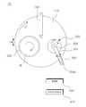
도 1은 종래의 화학 기계식 연마 장치를 개략적으로 도시한 도면이고, 도 2는 종래의 화학 기계식 연마 장치의 컨디셔너를 도시한 도면이다. 도 1 및 도 2를 참조하면, 종래의 화학 기계식 연마 장치(1)는, 상면에 연마패드(11)가 부착된 연마정반(10)과, 연마하고자 하는 웨이퍼(W)를 장착하여 연마패드(11)의 상면에 접촉하면서 회전하는 연마 헤드(20)와, 연마패드(11)의 표면을 미리 정해진 가압력으로 가압하면서 미세하게 절삭하여 연마패드(11)의 표면에 형성된 미공이 표면에 나오도록 컨디셔닝하는 컨디셔너(300)로 구성된다.1 is a view schematically showing a conventional chemical mechanical polishing device, and FIG. 2 is a view showing a conditioner of a conventional chemical mechanical polishing device. 1 and 2, the conventional chemical mechanical polishing apparatus 1 is equipped with a
연마정반(10)은 웨이퍼(W)가 연마되는 연마패드(11)가 부착되고, 회전축(12)이 회전 구동됨에 따라 회전 운동한다.The
연마 헤드(20)는 연마정반(10)의 연마패드(11)의 상면에 위치하여 웨이퍼(W)를 파지하는 캐리어 헤드(미도시)와, 캐리어 헤드를 회전 구동하면서 일정한 진폭만큼 왕복 운동을 행하는 연마 아암(미도시)으로 구성된다.The polishing
컨디셔너(30)는 연마패드(11)의 표면에 연마제와 화학 물질이 혼합된 슬러리를 담아두는 역할을 하는 수많은 발포 미공들이 막히지 않도록 연마패드(11)의 표면을 미세하게 절삭하여, 연마패드(11)의 발포 기공에 채워졌던 슬러리가 캐리어 헤드(21)에 파지된 웨이퍼(W)에 원활하게 공급하도록 한다.The
컨디셔너(30)는 회전축(32)과, 회전축(320)에 대해 상하 방향을 따라 이동 가능하게 결합되는 디스크 홀더(34)와, 디스크 홀더(34)의 저면에 배치되는 컨디셔닝 디스크(36)를 포함하며, 선회 경로를 따라 연마패드(11)에 대해 선회 이동하도록 구성된다.The
회전축(320)은 소정 각도 범위로 선회 운동하는 컨디셔너 아암에 장착되는 하우징(33) 상에 회전 가능하게 장착된다.The rotating
보다 구체적으로, 회전축(32)은, 구동 모터에 의하여 제자리에서 회전 구동되는 구동축 파트(32a), 구동축 파트(32a)와 맞물려 회전 구동되며 구동축 파트(32a)에 대해 상하 방향으로 상대 이동하는 전달축 파트(32c), 및 구동축 파트(32a)와 전달축 파트(32c)를 중공부에 수용하면서 그 둘레에 배치된 중공형 외주축 파트(32b)를 포함한다.More specifically, the
디스크 홀더(34)는 회전축(32)에 대해 상하 방향을 따라 이동 가능하게 제공되어, 회전축(32)과 함께 회전함과 아울러 회전축(32)에 대해 상하 방향으로 이동할 수 있으며, 디스크 홀더(34)의 하부에는 연마정반(10) 상에 부착된 연마패드(11)를 개질하기 위한 컨디셔닝 디스크(36)가 결합된다.The
회전축(32)과 디스크 홀더(34)의 사이에는 가압챔버(31)가 마련되며, 가압챔버(31)에 연결된 압력조절부(31a)로터 가압챔버(31)에 도달하는 공압을 조절함에 따라, 회전축(32)에 대해 디스크 홀더(34)가 상하 방향으로 이동할 수 있으며, 회전축(32)에 대한 디스크 홀더(34)의 상하 방향 이동에 대응하여 컨디셔닝 디스크(36)가 연마패드(11)를 가압하는 가압력이 변동될 수 있다.Between the rotating
한편, 연마패드(11)의 컨디셔닝 공정 중에, 컨디셔닝 디스크(36)의 가압력과 가압 시간 등과 같은 컨디셔닝 조건이 연마패드(11)의 컨디셔닝 상태 및 컨디셔닝 환경에 따라 최적화되지 않으면, 연마패드(11)의 컨디셔닝 안정성 및 효율이 저하되는 문제점이 있으므로, 연마패드(11)의 컨디셔닝 상태 및 컨디셔닝 환경에 따라 연마패드(11)의 컨디셔닝 조건이 최적화될 수 있어야 한다.On the other hand, during the conditioning process of the
그러나, 기존에는 가압챔버(31)에 인가되는 공압에 의하여 컨디셔닝 디스크(36)가 연마패드(11)를 가압하는 가압력을 조절하여 연마패드(11)의 컨디셔닝 정도를 제어함에 따라, 연마패드(11)의 컨디셔닝 균일도를 높이기 어려운 문제점이 있다.However, conventionally, the
특히, 맥동 또는 헌팅 현상 등에 의해 가압챔버(31)에 인가되는 공압이 일정하게 유지되지 못하면, 컨디셔닝 디스크(36)가 연마패드(11)를 가압하는 가압력이 균일하게 유지될 수 없고, 이로 인하여, 연마패드(11)의 컨디셔닝 안정성 및 효율이 저하되고, 연마패드(11)를 전체적으로 균일하게 컨디셔닝하기 어려운 문제점이 있다.In particular, if the pneumatic pressure applied to the
이에 따라, 최근에는 연마패드의 컨디셔닝 균일도를 높이고 컨디셔닝 효율을 향상시키기 위한 다양한 연구가 이루어지고 있으나, 아직 미흡하여 이에 대한 개발이 요구되고 있다.Accordingly, in recent years, various studies have been conducted to increase the conditioning uniformity of the polishing pad and improve the conditioning efficiency, but it is still insufficient to develop it.
본 발명은 연마패드의 컨디셔닝 정확도 및 안정성을 향상시킬 수 있는 화학 기계적 연마 장치의 컨디셔너를 제공하는 것을 목적으로 한다.An object of the present invention is to provide a conditioner of a chemical mechanical polishing apparatus capable of improving the conditioning accuracy and stability of the polishing pad.
또한, 본 발명은 연마패드의 컨디셔닝 효율을 향상시키고, 컨디셔닝 품질을 향상시킬 수 있도록 하는 것을 목적으로 한다.In addition, an object of the present invention is to improve the conditioning efficiency of the polishing pad and to improve the conditioning quality.
또한, 본 발명은 연마패드의 컨디셔닝 정밀도를 높이고, 컨디셔닝에 소요되는 시간을 단축할 수 있도록 하는 것을 목적으로 한다.In addition, it is an object of the present invention to increase the conditioning precision of the polishing pad and shorten the time required for conditioning.
또한, 본 발명은 연마패드의 표면 높이를 일정하게 유지하여 기판의 연마 품질을 향상시킬 수 있도록 하는 것을 목적으로 한다.In addition, an object of the present invention is to maintain a constant surface height of the polishing pad so as to improve the polishing quality of the substrate.
상술한 본 발명의 목적들을 달성하기 위한 본 발명은, 연마패드를 개질하는 컨디셔닝 디스크와, 컨디셔닝 디스크에 축방향 가압력을 인가하는 가압부와, 가압부에 의한 가압력을 측정하는 측정부와, 측정부에서 측정된 가압력에 기초하여 연마패드에 대한 컨디셔닝 디스크의 상대 속도 파라미터를 제어하는 제어부를 포함하는 화학 기계적 연마 장치의 컨디셔너를 제공한다.The present invention for achieving the above object of the present invention, a conditioning disk for modifying the polishing pad, a pressing unit for applying an axial pressing force to the conditioning disk, a measuring unit for measuring the pressing force by the pressing unit, and a measuring unit It provides a conditioner of a chemical mechanical polishing apparatus including a control unit for controlling a relative speed parameter of the conditioning disk with respect to the polishing pad based on the pressing force measured at.
상술한 바와 같이 본 발명에 따르면, 연마패드의 컨디셔닝 정확도 및 안정성을 향상시키는 유리한 효과를 얻을 수 있다.According to the present invention as described above, it is possible to obtain an advantageous effect of improving the conditioning accuracy and stability of the polishing pad.
특히, 본 발명에 따르면, 연마패드의 컨디셔닝 효율을 향상시키고, 컨디셔닝 품질을 향상시키는 유리한 효과를 얻을 수 있다.In particular, according to the present invention, it is possible to obtain an advantageous effect of improving the conditioning efficiency of the polishing pad and improving the conditioning quality.
또한, 본 발명에 따르면 연마패드의 컨디셔닝 정밀도를 높이고, 컨디셔닝에 소요되는 시간을 단축하는 유리한 효과를 얻을 수 있다.In addition, according to the present invention, it is possible to obtain an advantageous effect of increasing the conditioning precision of the polishing pad and shortening the time required for conditioning.
또한, 본 발명에 따르면 연마패드의 표면 높이를 일정하게 유지하여 웨이퍼의 연마 품질을 향상시키는 유리한 효과를 얻을 수 있다.In addition, according to the present invention, it is possible to obtain an advantageous effect of improving the polishing quality of the wafer by keeping the surface height of the polishing pad constant.
또한, 본 발명에 따르면 연마패드의 컨디셔닝 제어 분해능(resolution)을 향상시키는 유리한 효과를 얻을 수 있다.In addition, according to the present invention, it is possible to obtain an advantageous effect of improving the conditioning control resolution of the polishing pad.
도 1은 종래 일반적인 화학 기계적 연마 장치의 구성을 도시한 도면,
도 2는 도 1의 컨디셔너를 도시한 도면,
도 3 및 도 4는 본 발명에 따른 컨디셔너가 적용된 화학 기계적 연마 장치를 설명하기 위한 도면,
도 5는 본 발명에 따른 컨디셔너로서, 데이터 베이스를 설명하기 위한 도면,
도 6은 본 발명에 따른 컨디셔너로서, 연마패드에 대한 컨디셔닝 디스크의 상대 속도 파라미터를 제어하는 과정을 설명하기 위한 도면,
도 7은 본 발명에 따른 컨디셔너를 설명하기 위한 사시도,
도 8은 본 발명에 따른 컨디셔너를 설명하기 위한 절단사시도,
도 9는 본 발명에 따른 컨디셔너를 설명하기 위한 단면도,
도 10은 도 9의 'A'부위의 확대도,
도 11은 도 9의 'B"부위의 확대도,
도 12는 본 발명에 따른 컨디셔너로서, 측정부가 상부로 이동한 상태를 설명하기 위한 도면이다.1 is a view showing the configuration of a conventional chemical mechanical polishing apparatus,
2 is a view showing the conditioner of FIG. 1,
3 and 4 are views for explaining a chemical mechanical polishing apparatus to which the conditioner according to the present invention is applied,
5 is a conditioner according to the present invention, a view for explaining a database,
Figure 6 is a conditioner according to the present invention, a view for explaining a process for controlling the relative speed parameter of the conditioning disk for the polishing pad,
7 is a perspective view for explaining a conditioner according to the present invention,
8 is a cut perspective view for explaining a conditioner according to the present invention,
9 is a cross-sectional view for explaining a conditioner according to the present invention,
10 is an enlarged view of a portion 'A' of FIG. 9,
11 is an enlarged view of a portion 'B' of FIG. 9,
12 is a conditioner according to the present invention, a view for explaining a state in which the measurement unit moves upward.
이하 첨부된 도면들을 참조하여 본 발명의 바람직한 실시예를 상세하게 설명하지만, 본 발명이 실시예에 의해 제한되거나 한정되는 것은 아니다. 참고로, 본 설명에서 동일한 번호는 실질적으로 동일한 요소를 지칭하며, 이러한 규칙 하에서 다른 도면에 기재된 내용을 인용하여 설명할 수 있고, 당업자에게 자명하다고 판단되거나 반복되는 내용은 생략될 수 있다.Hereinafter, preferred embodiments of the present invention will be described in detail with reference to the accompanying drawings, but the present invention is not limited or limited by the embodiments. For reference, in the present description, the same numbers refer to substantially the same elements, and the contents described in other drawings may be cited and described under these rules, and repeated contents that are deemed to be obvious to those skilled in the art or may be omitted.
도 3 및 도 4는 본 발명에 따른 컨디셔너가 적용된 화학 기계적 연마 장치를 설명하기 위한 도면이고, 도 5는 본 발명에 따른 컨디셔너로서, 데이터 베이스를 설명하기 위한 도면이며, 도 6은 본 발명에 따른 컨디셔너로서, 연마패드에 대한 컨디셔닝 디스크의 상대 속도 파라미터를 제어하는 과정을 설명하기 위한 도면이다. 그리고, 도 7은 본 발명에 따른 컨디셔너를 설명하기 위한 사시도이고, 도 8은 본 발명에 따른 컨디셔너를 설명하기 위한 절단사시도이다. 또한, 도 9는 본 발명에 따른 컨디셔너를 설명하기 위한 단면도이고, 도 10은 도 9의 'A'부위의 확대도이며, 도 11은 도 9의 'B"부위의 확대도이다. 또한, 도 12는 본 발명에 따른 컨디셔너로서, 측정부가 상부로 이동한 상태를 설명하기 위한 도면이다.3 and 4 are views for explaining a chemical mechanical polishing apparatus to which a conditioner according to the present invention is applied, FIG. 5 is a conditioner according to the present invention, a view for explaining a database, and FIG. 6 is according to the present invention As a conditioner, a view for explaining a process of controlling a relative speed parameter of a conditioning disk with respect to a polishing pad. And, Figure 7 is a perspective view for explaining the conditioner according to the present invention, Figure 8 is a perspective view for cutting the conditioner according to the present invention. In addition, FIG. 9 is a cross-sectional view for explaining the conditioner according to the present invention, FIG. 10 is an enlarged view of the 'A' portion of FIG. 9, and FIG. 11 is an enlarged view of the 'B' portion of FIG. 12 is a conditioner according to the present invention, a view for explaining a state in which the measurement unit moves upward.
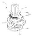
도 3 내지 도 12를 참조하면, 본 발명에 따른 화학 기계적 연마 장치의 컨디셔너(300)는, 연마패드(110)를 개질하는 컨디셔닝 디스크(370)와, 컨디셔닝 디스크(370)에 축방향 가압력을 인가하는 가압부(310)와, 가압부(310)에 의한 가압력을 측정하는 측정부(330)와, 측정부(330)에서 측정된 가압력에 기초하여 연마패드(110)에 대한 컨디셔닝 디스크(370)의 상대 속도 파라미터를 제어하는 제어부(400)를 포함한다.3 to 12, the
이는, 연마패드(110)의 컨디셔닝 정확도 및 안정성을 향상시키기 위함이다.This is to improve the conditioning accuracy and stability of the
즉, 연마패드의 컨디셔닝 공정 중에, 연마패드의 컨디셔닝 조건이 연마패드의 컨디셔닝 상태 및 컨디셔닝 환경에 따라 최적화되지 않으면, 연마패드의 컨디셔닝 안정성 및 효율이 저하되는 문제점이 있으므로, 연마패드의 컨디셔닝 상태 및 컨디셔닝 환경에 따라 연마패드의 컨디셔닝 조건이 최적화될 수 있어야 한다.That is, during the conditioning process of the polishing pad, if the conditioning conditions of the polishing pad are not optimized according to the conditioning state and the conditioning environment of the polishing pad, there is a problem that the conditioning stability and efficiency of the polishing pad are deteriorated, so the conditioning state and conditioning of the polishing pad Conditioning conditions of the polishing pad should be optimized according to the environment.
그러나, 기존에는 공압에 의하여 컨디셔닝 디스크가 연마패드를 가압하는 가압력을 조절하여 연마패드의 컨디셔닝 정도를 제어함에 따라, 연마패드의 컨디셔닝 균일도를 높이기 어려운 문제점이 있다. 특히, 맥동 또는 헌팅 현상 등에 의해 공압이 일정하게 유지되지 못하면, 컨디셔닝 디스크가 연마패드를 가압하는 가압력이 균일하게 유지될 수 없고, 이로 인하여, 연마패드의 컨디셔닝 안정성 및 효율이 저하되고, 연마패드를 전체적으로 균일하게 컨디셔닝하기 어려운 문제점이 있다.However, conventionally, as the conditioning disk controls the degree of conditioning of the polishing pad by controlling the pressing force for pressing the polishing pad by pneumatic pressure, there is a problem that it is difficult to increase the conditioning uniformity of the polishing pad. In particular, if the pneumatic pressure is not kept constant due to a pulsation or hunting phenomenon, the pressing force for the conditioning disk to press the polishing pad cannot be maintained uniformly, thereby reducing the conditioning stability and efficiency of the polishing pad and reducing the polishing pad. There is a problem that it is difficult to condition uniformly as a whole.
하지만, 본 발명은 컨디셔닝 디스크(370)에 인가되는 가압력에 기초하여 연마패드(110)에 대한 컨디셔닝 디스크(370)의 상대 속도 파라미터를 제어하는 것에 의하여, 맥동 또는 헌팅 현상 등에 의한 컨디셔닝 균일도 저하를 방지할 수 있으므로, 연마패드(110)의 컨디셔닝 정확도를 높이고, 컨디셔닝 효율 및 안정성을 향상시키는 유리한 효과를 얻을 수 있다.However, according to the present invention, by controlling the relative speed parameter of the
더욱이, 본 발명은 연마패드(110)에 대한 컨디셔닝 디스크(370)의 상대 속도 파라미터를 제어하여 연마패드(110)의 컨디셔닝 정도를 조절하는 것에 의하여, 연마패드(110)의 컨디셔닝 제어 분해능(resolution)을 높일 수 있으므로, 보다 정밀한 컨디셔닝 제어가 가능한 이점이 있다.Moreover, the present invention controls the control degree of the conditioning of the
가압부(310)는 컨디셔닝 디스크(370)에 축방향 가압력을 인가하도록 마련된다.The
가압부(310)는 요구되는 조건 및 설계 사양에 따라 다양한 방식으로 컨디셔닝 디스크(370)에 축방향 가압력을 인가하도록 구성될 수 있다. 일 예로, 컨디셔닝 디스크(370)의 상부에는 컨디셔닝 디스크(370)를 회전시키는 회전부(350)가 결합되고, 가압부(310)는 회전부(350)의 상부에 구비되어 회전부(350)에 축방향 가압력(하향력)을 선택적으로 인가한다.The
가압부(310)로서는 회전부(350)에 가압력을 인가할 수 있는 다양한 가압력 인가 수단이 사용될 수 있으며, 가압부(310)의 종류 및 구조에 의해 본 발명이 제한되거나 한정되는 것은 아니다.Various pressing force applying means capable of applying a pressing force to the rotating
일 예로, 가압부(310)는, 압력챔버(313)가 형성된 실린더 몸체(312)와, 압력챔버(313)의 압력 변화에 따라 상하 방향을 따라 이동 가능하게 실린더 몸체(312)에 장착되며 측정부(330)와 결합되는 피스톤부재(316)를 포함한다.For example, the
보다 구체적으로, 도 10을 참조하면, 압력챔버(313)는, 피스톤부재(316)의 하부에 형성되는 제1챔버(313a)와, 피스톤부재(316)의 상부에 형성되는 제2챔버(313b)를 포함하며, 제1챔버(313a)와 제2챔버(313b) 중 어느 하나 이상의 압력을 제어하는 것에 의하여 피스톤부재(316)를 상하 방향을 따라 이동시킬 수 있다.More specifically, referring to FIG. 10, the
바람직하게, 제1압력챔버(313)에는 균일한 범위의 고정압(P1)이 인가되고, 제2압력챔버(313)에는 선택적으로 변화되는 변동압(P2)이 인가된다. 이를 위해, 제1압력챔버(313)에는 균일한 범위의 고정압(P1)을 인가하는 제1압력형성부(314a)가 연결되고, 제2압력챔버(313)에는 선택적으로 변화되는 변동압(P2)을 인가하는 제2압력형성부(314b)가 연결된다.Preferably, a fixed pressure P1 in a uniform range is applied to the
일 예로, 제1압력챔버(313)에 고정압(P1)이 일정하게 유지되는 상태에서, 고정압(P1)보다 높은 변동압(P2)이 제2압력챔버(313)에 인가되면, 변동압(P2)과 고정압(P1) 간의 압력 차이 만큼 피스톤부재(316)가 하부로 이동하며 회전부(350)를 가압하게 된다.(도 11 참조) 이와 반대로, 제1압력챔버(313)에 고정압(P1)이 일정하게 유지되는 상태에서, 고정압(P1)보다 낮은 변동압(P2)이 제2압력챔버(313)에 인가되면, 변동압(P2)과 고정압(P1) 간의 압력 차이 만큼 피스톤부재(316)가 상부로 이동하게 된다.(도 12 참조)For example, in the state where the fixed pressure P1 is kept constant in the
이와 같이, 제1압력챔버(313)에는 고정압(P1)이 일정하게 유지되고, 제2압력챔버(313)에 인가되는 변동압(P2)의 압력 변화에 따라 피스톤부재(316)가 상하 방향으로 이동하도록 하는 것에 의하여, 가압부(310)에 의한 가압력을 보다 정확하게 제어하고, 가압부(310)의 가압력 제어 분해능(resolution)을 향상시키는 유리한 효과를 얻을 수 있다. 특히, 압력형성부(예를 들어, 펌프)의 최소 압력 조절 단위보다 작은 단위로 변동압과 고정압의 차이를 형성할 수 있으므로, 피스톤부재(316)의 이동을 보다 정밀하게 제어하는 유리한 효과를 얻을 수 있다.As described above, the fixed pressure P1 is kept constant in the
더욱이, 제1압력챔버(313)에는 고정압(P1)이 일정하게 유지되고, 제2압력챔버(313)에 인가되는 변동압(P2)의 압력 변화에 따라 피스톤부재(316)가 상하 방향으로 이동하도록 하는 것에 의하여, 제2압력챔버(313)에 변동압이 인가되지 않은 상태(예를 들어, 변동압이 '0'인 상태)에서 가압부(310)(가압부에 고정된 구성 요소 포함)의 하중에 의한 가압력이 회전부(350)에 작용하는 것을 방지하는 유리한 효과를 얻을 수 있다.Furthermore, the fixed pressure P1 is kept constant in the
참고로, 본 발명의 실시예에서는 가압부(310)의 압력챔버(313)가 복수개의 챔버를 포함하여 구성된 예를 들어 설명하고 있지만, 본 발명의 다른 실시예에 따르면 가압부의 압력챔버가 단일 챔버만으로 구성되는 것도 가능하다.For reference, in the exemplary embodiment of the present invention, the
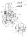
도 8 및 도 9를 참조하면, 회전부(350)는 컨디셔너 하우징(302)의 내부에 회전 가능하게 배치되며, 가압부(310)의 하부에 위치하여 가압부(310)에 의해 선택적으로 가압되도록 구성된다.8 and 9, the
이때, 컨디셔너 하우징(302)은 스윙회전축(304a)을 기준으로 하여 소정 각도 범위로 스윙 회전(선회 운동)하는 스윙암(304)에 장착된다.At this time, the
회전부(350)는 컨디셔너 하우징(302) 상에 회전 가능한 다양한 구조로 제공될 수 있다. 일 예로, 회전부(350)는, 컨디셔닝 디스크(370)에 결합되는 스플라인축(352)과, 스플라인축(352)의 둘레를 감싸도록 결합되며 제1커플러(340)를 지지하는 링 형태의 베어링부재(354)를 포함한다.The
여기서, 스플라인축(352)과 컨디셔닝 디스크(370)가 결합된다 함은, 스플라인축(352)과 컨디셔닝 디스크(370)가 일체로 회전 가능하게 결합된 것으로 정의된다.Here, that the
스플라인축(352)으로서는 통상의 스플라인이 사용될 수 있으며, 스플라인축(352)의 종류에 의해 본 발명이 제한되거나 한정되는 것은 아니다. 일 예로, 스플라인축(352)으로서는 볼스플라인이 사용될 수 있다.As the
도 3 및 도 4를 참조하면, 회전부(350)는 구동원(392)에 의해 컨디셔너 하우징(302)의 내부에서 회전하도록 구성된다.3 and 4, the
바람직하게, 회전부(350)를 회전시키기 위한 구동력을 발생시키는 구동원(392)(예를 들어, 모터)은, 컨디셔너 하우징(302)과 이격되게 스윙암(304)에 장착되며, 구동원(392)의 구동력은 동력전달부(394)에 의해 회전부(350)로 전달된다.Preferably, a driving source 392 (eg, a motor) that generates a driving force for rotating the
동력전달부(394)는 구동원(392)의 구동력을 회전부(350)로 전달 가능한 다양한 구조로 형성될 수 있다. 일 예로, 동력전달부(394)는 구동원(392)에 의해 회전하는 제1기어(394a)와, 회전부(350)에 결합되며 제1기어(394a)에 치합되어 회전하는 제2기어(394b)를 포함한다. 이때, 제1기어(394a)와 제2기어(394b)로서는 통상의 베벨 기어가 사용될 수 있다. 경우에 따라서는 피니언기어와 같은 여타 다른 기어를 이용하여 동력전달부를 구성하는 것도 가능하다.The
회전부(350)와 구동원(392) 간의 연결 구조는 요구되는 조건 및 설계 사양에 따라 다양하게 변경될 수 있다. 일 예로, 회전부(350)는 컨디셔너 하우징(302)의 내부에 회전 가능하게 결합되는 회전블럭(356)과 일체로 회전하도록 구성되며, 제2기어(394b)는 회전블럭(356)에 결합된다. 구동원(392)에 의해 회전블럭(356)이 회전함과 동시에 회전부(350)가 함께 회전할 수 있다.The connection structure between the
또한, 구동원(392)과 동력전달부(394)의 사이에는 구동원(392)의 구동력을 감속하기 위한 감속기(예를 들어, 감속비 1:5의 감속기)가 구비될 수 있다.Further, a reduction gear (for example, a reduction gear having a reduction ratio of 1: 5) for decelerating the driving force of the driving
이와 같이, 회전부(350)를 회전시키는 구동원(392)을 컨디셔너 하우징(302)과 이격되게 스윙암(304)에 장착하는 것에 의하여, 컨디셔닝 헤드부(스윙암의 단부의 위치하며, 가압부 및 컨디셔닝 디스크(370)를 포함하는 부위)의 처짐을 최소화하고, 구동원(392)의 방열 성능을 높이는 유리한 효과를 얻을 수 있다.In this way, by mounting the
즉, 기존에는 회전부를 회전시키는 구동원이 스윙암의 단부의 위치하는 컨디셔닝 헤드부에 장착됨에 따라, 구동원에 하중에 의해 스윙암의 단부의 처짐이 발생하는 문제점이 있고, 스윙암의 처짐이 발생한 상태에서 컨디셔닝 공정이 행해지면 연마패드(110)가 불균일하게 개질되는 문제점이 있다. 더욱이, 기존에는 컨디셔닝 헤드부의 협소한 공간에 가압부 및 구동원 등이 모두 밀집되게 장착됨에 따라, 구동원의 방열 성능이 저하되는 문제점이 있다.That is, conventionally, as the driving source for rotating the rotating part is mounted on the conditioning head located at the end of the swing arm, there is a problem that the end of the swing arm is deflected by the load on the driving source, and the swing arm is deflected. In the conditioning process is performed, there is a problem that the
하지만, 본 발명은 회전부(350)를 회전시키는 구동원(392)을 컨디셔너 하우징(302)과 이격되게 스윙암(304)에 장착하는 것에 의하여, 구동원(392)에 하중에 의한 스윙암(304)의 처짐을 방지하고, 연마패드(110)의 컨디셔닝 안정성을 향상시키는 유리한 효과를 얻을 수 있다. 또한, 협소한 공간을 갖는 컨디셔닝 헤드부로부터 구동원(392)을 분리시키는 것에 의하여, 구동원(392)의 방열 성능을 높일 수 있으며, 컨디셔닝 헤드부의 설계자유도 및 공간활용성을 높이는 유리한 효과를 얻을 수 있다.However, according to the present invention, by mounting the
도 8을 참조하면, 측정부(330)는 가압부(310)에 의해 컨디셔닝 디스크(370)에 인가되는 가압력을 측정하도록 마련된다.Referring to FIG. 8, the measuring
일 예로, 측정부(330)는 가압부(310)와 컨디셔닝 디스크(370)의 사이에 구비되며, 연마패드(110)의 컨디셔닝이 행해지는 중에, 가압부(310)에 의해 컨디셔닝 디스크(370)에 인가되는 가압력을 측정한다.For example, the
기존에는 연마패드(110)의 컨디셔닝이 행해지는 중에, 컨디셔닝 디스크(370)가 연마패드(110)를 가압하는 가압력을 정확하게 측정하기 어렵고, 연마패드(110)의 표면 높이 편차에 따라 컨디셔닝 디스크(370)가 연마패드(110)를 가압하는 가압력을 정확하게 제어할 수 없으므로, 연마패드(110)의 컨디셔닝 안정성 및 효율이 저하되고, 연마패드(110)를 전체적으로 균일하게 컨디셔닝하기 어려운 문제점이 있다.Conventionally, during conditioning of the
하지만, 본 발명은 가압부(310)와 회전부(350)의 사이에 측정부(330)를 마련하고, 측정부(330)가 가압부(310)에 의한 가압력을 회전부(350)로 전달하면서 가압력을 측정하도록 하는 것에 의하여, 컨디셔닝 공정 중에 컨디셔닝 디스크(370)가 연마패드(110)를 가압하는 가압력을 정확하게 측정하고 제어하는 유리한 효과를 얻을 수 있다.However, the present invention provides a measuring
측정부(330)로서는 가압력을 측정 가능한 다양한 측정수단이 사용될 수 있으며, 측정부(330)의 종류는 요구되는 조건 및 설계 사양에 따라 다양하게 변경될 수 있다. 일 예로, 측정부(330)로서는 로드셀이 사용될 수 있으며, 로드셀의 하단은 회전부(350)에 점접촉되도록 원호형 단면 형태로 형성된다.Various measuring means capable of measuring the pressing force may be used as the measuring
전술 및 도시한 본 발명의 실시예에서는, 가압부(310)와 회전부(350)의 사이에 측정부(330)가 마련된 예를 들어 설명하고 있지만, 본 발명의 다른 실시예에 따르면, 측정부를 컨디셔너의 여타 다른 위치에 장착하거나, 컨디셔너의 외측 또는 다른 장비(예를 들어, 지그)에 장착하는 것도 가능하다.In the above-described and illustrated embodiments of the present invention, an example in which the
측정부(330)는 회전부(350)에 직접 접촉되거나 별도의 부재를 매개로 접촉될 수 있다.The
일 예로, 회전부(350)의 상부에는 제1커플러(340)가 고정 결합되되, 측정부(330)가 가압부(310)에 의해 하부로 이동하면 측정부(330)가 제1커플러(340)에 접촉되며 가압력이 제1커플러(340)를 거쳐 회전부(350)에 전달되고, 측정부(330)가 가압부(310)에 의해 상부로 이동하면 측정부(330)가 제1커플러(340)로부터 이격된다.For example, the
보다 구체적으로, 도 11을 참조하면, 측정부(330)로부터 제1커플러(340)에 전달된 가압력은 베어링부재(354)를 거쳐 스플라인축(352)에 전달된다.More specifically, referring to FIG. 11, the pressing force transmitted from the measuring
바람직하게, 제1커플러(340)는 베어링부재(354)의 원주 방향을 따라 연속적으로 베어링부재(354)에 지지되고, 제1커플러(340)에 전달된 가압력(F1)은 베어링부재(354)를 따라 링 형태로 분산(F2)된 상태로 스플라인축(352)에 전달된다.Preferably, the
이와 같이, 제1커플러(340)에 전달된 가압력(F1)이 베어링부재(354)를 따라 링 형태로 분산(F2)된 상태로 스플라인축(352)에 전달되도록 하는 것에 의하여, 스플라인축(352)의 유동 및 흔들림을 최소화하면서, 제1커플러(340)에 전달된 가압력을 보다 안정적으로 스플라인축(352)에 전달하는 유리한 효과를 얻을 수 있다.As described above, the
즉, 제1커플러에 전달된 가압력이 스플라인축에 직접 전달되도록 구성하는 것도 가능하다. 하지만, 조립 공차 및 오차 등에 의하여 제1커플러와 스플라인축이 비동축적으로 배치된 경우에는, 가압부의 가압력(제1커플러로 전달된 가압력)이 스플라인축의 중심이 아닌 스플라인축의 중심으로부터 이격된 부위에 전달됨에 따라 스플라인축의 유동 및 흔들림을 유발하는 문제점이 있다.That is, it is also possible to configure the pressing force transmitted to the first coupler to be directly transmitted to the spline shaft. However, when the first coupler and the spline shaft are arranged non-coaxially due to assembly tolerances and errors, the pressing force of the pressing portion (the pressing force transmitted to the first coupler) is transmitted to a part spaced apart from the center of the spline shaft, not the center of the spline shaft. Accordingly, there is a problem that causes the flow and shaking of the spline shaft.
하지만, 본 발명은 제1커플러(340)에 전달된 가압력이 베어링부재(354)를 따라 링 형태로 분산된 상태로 스플라인축(352)에 동축적으로 전달되도록 하는 것에 의하여, 스플라인축(352)의 유동 및 흔들림없이 가압력을 스플라인축(352)에 안정적으로 전달하는 유리한 효과를 얻을 수 있다.However, according to the present invention, the
또한, 가압부(310)의 하부에는 가압부(310)에 의해 선택적으로 상하 방향으로 이동하는 제2커플러(320)가 구비될 수 있고, 측정부(330)는 제2커플러(320)에 고정 결합된다.In addition, a
바람직하게, 제2커플러(320)는 제1커플러(340)의 측면 둘레를 감싸는 원통 형상으로 형성되되, 제2커플러(320)의 측벽에는 가이드홀(322)이 형성되고, 제1커플러(340)의 둘레면에는 가이드홀(322)에 상하 이동 가능하게 수용되는 가이드돌기(342)가 돌출 형성된다.Preferably, the
이와 같이, 제2커플러(320)가 제1커플러(340)의 둘레를 감싼 상태로 상하 이동하면서, 가이드 돌기가 가이드홀(322)을 따라 상하 이동하도록 하는 것에 의하여, 제1커플러(340)(또는 회전부)에 대한 제2커플러(320)(또는 측정부)의 상하 이동을 보다 안정적으로 지지하는 유리한 효과를 얻을 수 있다. 또한, 가이드돌기(342)와 가이드홀(322)과의 간섭에 의하여, 제1커플러(340)에 대한 제2커플러(320)의 과도한 상하 이동이 제한될 수 있다.In this way, the
컨디셔닝 디스크(370)는 회전부(350)의 하부에 결합되며, 가압부(310)의 가압력에 의해 가압된 상태로 회전부(350)에 의해 회전하면서 연마패드(110)를 개질(컨디셔닝)한다.The
일 예로, 회전부(350)의 하단에는 디스크 홀더(360)가 장착되고, 디스크 홀더(360)에는 연마정반(100) 상에 부착된 연마패드(110)를 개질하기 위한 컨디셔닝 디스크(370)가 결합된다.For example, a
여기서, 컨디셔닝 디스크(370)가 연마패드(110)를 컨디셔닝한다 함은, 연마패드(110)의 표면을 미리 정해진 가압력(P)으로 가압하며 미세하게 절삭하여 연마패드(110)의 표면에 형성된 미공이 표면에 나오도록 개질시키는 것으로 정의된다. 다시 말해서, 컨디셔닝 디스크(370)는 연마패드(110)의 외표면에 연마제와 화학 물질이 혼합된 슬러리를 담아두는 역할을 하는 수많은 발포 미공들이 막히지 않도록 연마패드(110)의 외표면을 미세하게 절삭하여, 연마패드(110)의 발포 기공에 채워졌던 슬러리가 기판에 원활하게 공급되게 한다. 경우에 따라서는 컨디셔닝 디스크(370)에 연마패드(110)의 미소 절삭을 위하여 연마패드(110)와 접촉하는 면에 다이아몬드 입자를 부착하는 것도 가능하다.Here, the condition that the
회전부(350)와 디스크 홀더(360)의 결합 및 연결구조는 요구되는 조건 및 설계 사양에 따라 다양하게 변경될 수 있으며, 회전부(350)와 디스크 홀더(360)의 결합 및 연결구조에 의해 본 발명이 제한되거나 한정되는 것은 아니다.The coupling and connection structure of the
일 예로, 회전부(350)와 디스크 홀더(360)는 짐벌구조체(362)에 의해 연결될 수 있다. 짐벌구조체(362)는 회전부(350)에 대해 디스크 홀더(360)를 자동 조심(self-aligning)시키도록 구성된다.For example, the
보다 구체적으로, 컨디셔너(300)에 의해 연마패드(110)의 컨디셔닝 공정이 진행되는 동안, 연마패드(110)의 표면 상태 또는 컨디셔닝 디스크(370)에 역방향으로 작용하는 물리적인 힘에 의해 컨디셔너 하우징(302)이 틸팅(수직 선상에 대해 기울어지게 배치)되는 현상이 발생하게 되면, 컨디셔닝 디스크(370)가 연마패드(110)로부터 부분적으로 이격됨에 따라 연마패드(110)의 컨디셔닝이 균일하게 이루어지지 못하는 문제점이 있다. 이를 위해, 짐벌구조체(362)는 컨디셔너 하우징(302)이 틸팅될 시 컨디셔너 하우징(302)에 대한 디스크 홀더(360)의 짐벌(gimbal) 운동이 허용되게 함으로써, 컨디셔너 하우징(302)이 틸팅되더라도 컨디셔닝 디스크(370)가 연마패드(110)에 접촉된 상태를 유지할 수 있게 한다.More specifically, during the conditioning process of the
일 예로, 짐벌구조체(362)로서는 유니버셜 조인트 또는 자동조심베어링(self-aligning bearing) 등이 사용될 수 있다. 여기서, 자동조심베어링이라 함은, 통상의 자동조심볼베어링 및 자동조심롤러베어링을 모두 포함하는 개념으로 정의된다.As an example, the
아울러, 회전부(350)에 대해 디스크 홀더(360)를 틸팅시키는 외력이 해제되면, 짐벌구조체(362)는 스프링과 같은 탄성부재에 의해 디스크 홀더(360)가 초기 위치(디스크 홀더(360)가 컨디셔너 하우징(302)에 대해 틸팅되기 전 상태)로 자동적으로 복귀하도록 구성될 수 있다.In addition, when the external force for tilting the
이와 같이, 회전부(350)에 대한 디스크 홀더(360)의 짐벌 운동이 보장되도록 하는 것에 의하여, 컨디셔닝 공정 중에 컨디셔너 하우징(302)(또는 회전부)의 틸팅이 발생되어도, 컨디셔닝 디스크(370)가 연마패드(110)에 밀착된 상태를 안정적으로 유지하고 컨디셔닝 디스크(370)에 인가되는 가압력을 균일하게 유지하는 유리한 효과를 얻을 수 있다.In this way, by ensuring the gimbal movement of the
도 4 내지 도 6을 참조하면, 제어부(400)는 측정부(330)에서 측정된 가압력(F)에 기초하여 연마패드(110)에 대한 컨디셔닝 디스크(370)의 상대 속도 파라미터를 제어한다.4 to 6, the
참고로, 본 발명에서 연마패드(110)에 대한 컨디셔닝 디스크(370)의 상대 속도 파라미터라 함은, 연마패드(110)의 컨디셔닝에 영향을 미치는 연마패드(110)에 대한 컨디셔닝 디스크(370)의 상대 속도에 관한 변수를 모두 포함하는 것으로 정의된다.For reference, the relative speed parameter of the
일 예로, 연마패드(110)에 대한 컨디셔닝 디스크(370)의 상대 속도 파라미터는, 컨디셔닝 디스크(370)의 회전 속도(V1)를 포함한다. 다른 일 예로, 연마패드(110)에 대한 컨디셔닝 디스크(370)의 상대 속도 파라미터는, 연마패드(110)의 회전 속도(V2)를 포함한다.For example, the relative speed parameter of the
또 다른 일 예로, 연마패드(110)에 대한 컨디셔닝 디스크(370)의 상대 속도 파라미터는, 연마패드(110)에 대한 컨디셔닝 디스크(370)의 스윙 이동 속도(V3)를 포함한다. 또 다른 일 예로, 연마패드(110)에 대한 컨디셔닝 디스크(370)의 상대 속도 파라미터는, 컨디셔닝 디스크(370)에 대한 연마패드(110)의 오실레이션 이동 속도(V4)를 포함한다.As another example, the relative speed parameter of the
여기서, 컨디셔닝 디스크(370)의 스윙 이동 속도(V3)라 함은, 컨디셔닝 디스크(370)가 스윙회전축(304a)을 기준으로 스윙 회전하는 속도를 의미한다. 또한, 연마패드(110)의 오실레이션 이동 속도(V4)라 함은, 컨디셔닝 디스크(370)에 대해 연마패드(110)가 미리 정해진 방향(예를 들어, 연마패드의 직경 방향)을 따라 왕복 이동하는 속도를 의미한다.Here, the swing movement speed V3 of the
보다 구체적으로, 제어부(400)는, 컨디셔닝 디스크(370)에 인가되는 가압력이 증가하면 연마패드(110)에 대한 컨디셔닝 디스크(370)의 상대 속도 파라미터를 낮추고, 이와 반대로, 컨디셔닝 디스크(370)에 인가되는 가압력이 감소하면 연마패드(110)에 대한 컨디셔닝 디스크(370)의 상대 속도 파라미터를 높이도록 구성된다.More specifically, when the pressing force applied to the
일 예로, 제어부(400)는 컨디셔닝 디스크(370)에 인가되는 가압력이 증가하면 컨디셔닝 디스크(370)의 회전 속도(V1)를 낮추고, 이와 반대로, 컨디셔닝 디스크(370)에 인가되는 가압력이 감소하면 컨디셔닝 디스크(370)의 회전 속도(V1)를 높인다.For example, the
다른 일 예로, 제어부(400)는 컨디셔닝 디스크(370)에 인가되는 가압력이 증가하면 연마패드(110)의 회전 속도(V2)를 낮추고, 이와 반대로, 컨디셔닝 디스크(370)에 인가되는 가압력이 감소하면 연마패드(110)의 회전 속도(V2)를 높인다.As another example, when the pressing force applied to the
또 다른 일 예로, 제어부(400)는 컨디셔닝 디스크(370)에 인가되는 가압력이 증가하면 컨디셔닝 디스크(370)의 스윙 이동 속도(V3)를 낮추고, 이와 반대로, 컨디셔닝 디스크(370)에 인가되는 가압력이 감소하면 컨디셔닝 디스크(370)의 스윙 이동 속도(V3)를 높인다.As another example, when the pressing force applied to the
또 다른 일 예로, 제어부(400)는 컨디셔닝 디스크(370)에 인가되는 가압력이 증가하면 연마패드(110)의 오실레이션 이동 속도(V4)를 낮추고, 이와 반대로, 컨디셔닝 디스크(370)에 인가되는 가압력이 감소하면 연마패드(110)의 오실레이션 이동 속도(V4)를 높인다.As another example, when the pressing force applied to the
이와 같이, 제어부(400)는 컨디셔닝 디스크(370)의 회전 속도(V1), 연마패드(110)의 회전 속도(V2), 컨디셔닝 디스크(370)의 스윙 이동 속도(V3), 연마패드(110)의 오실레이션 이동 속도(V4)를 제어하는 것에 의하여, 연마패드(110)의 컨디셔닝 정도(예를 들어, 연마패드 절삭량)를 제어할 수 있다.In this way, the
이때, 제어부(400)는 측정부(330)에서 측정된 가압력(F)에 기초하여 컨디셔닝 디스크(370)의 회전 속도(V1), 연마패드(110)의 회전 속도(V2), 컨디셔닝 디스크(370)의 스윙 이동 속도(V3), 연마패드(110)의 오실레이션 이동 속도(V4) 중 어느 하나만을 제어할 수 있다. 본 발명의 다른 실시예에 따르면, 제어부(400)가 측정부(330)에서 측정된 가압력(F)에 기초하여 컨디셔닝 디스크(370)의 회전 속도(V1), 연마패드(110)의 회전 속도(V2), 컨디셔닝 디스크(370)의 스윙 이동 속도(V3), 연마패드(110)의 오실레이션 이동 속도(V4) 중 어느 하나 이상을 동시에 또는 순차적으로 제어하는 것도 가능하다.At this time, the
바람직하게, 제어부(400)는 측정부(330)에서 측정된 가압력(F)에 기초하여, 연마패드(110)에 대한 컨디셔닝 공정이 완료되기 전에, 연마패드(110)의 컨디셔닝에 영향을 미치는 연마패드(110)에 대한 컨디셔닝 디스크(370)의 상대 속도에 관한 상대 속도 파라미터를 제어한다. 바람직하게, 측정부는 연마패드(110)에 대한 컨디셔닝 공정이 행해지는 중에 실시간으로 컨디셔닝 디스크(370)에 인가되는 가압력을 측정하고, 제어부(400)는 측정부에서 가압력에 기초하여 연마패드(110)에 대한 컨디셔닝 디스크(370)의 상대 속도 파라미터를 실시간으로 제어한다.Preferably, the
더욱 바람직하게, 연마패드(110)에 대한 컨디셔닝 디스크(370)의 상대 속도 파라미터는 데이터 베이스에 미리 저장되고, 제어부(400)는 가압력 별로 서로 다른 복수개의 상대 속도 파라미터가 저장된 데이터 데이스(410)에서 어느 하나 이상의 상대 속도 파라미터를 호출하도록 구성된다.More preferably, the relative speed parameter of the
일 예로, 도 5를 참조하면, 연마패드(110)에 대한 컨디셔닝 디스크(370)의 상대 속도 파라미터는 컨디셔닝 디스크(370)에 인가되는 가압력별로 룩업테이블(Lookup Table)에 미리 저장되며, 룩업테이블에 미리 저장된 정보를 이용하여 연마패드(110)에 대한 컨디셔닝 디스크(370)의 상대 속도 파라미터를 빠르게 획득할 수 있다.For example, referring to FIG. 5, the relative speed parameter of the
구체적으로, 컨디셔닝 디스크(370)에 인가되는 가압력이 측정되면, 측정된 가압력에 적합한 컨디셔닝 디스크(370)의 회전 속도(V1), 연마패드(110)의 회전 속도(V2), 컨디셔닝 디스크(370)의 스윙 이동 속도(V3), 연마패드(110)의 오실레이션 이동 속도(V4)와 관련된 상대 속도 파라미터가 호출될 수 있다.Specifically, when the pressing force applied to the
그리고, 룩업테이블에 미리 저장되지 않은 상대 속도 파라미터는, 미리 저장된 인접한 상대 속도 파라미터에서의 오차를 이용한 보간법(interpolation)으로 산출될 수 있다.Further, the relative speed parameter not previously stored in the lookup table may be calculated by interpolation using an error in the adjacent relative speed parameter stored in advance.
이와 같이, 측정부(330)에서 측정된 가압력(F)에 기초하여 연마패드(110)에 대한 컨디셔닝 디스크(370)의 상대 속도 파라미터를 제어하는 것에 의하여, 연마패드(110)의 컨디셔닝 정확도 및 안정성을 향상시키는 유리한 효과를 얻을 수 있다.As described above, by controlling the relative speed parameter of the
즉, 연마패드의 컨디셔닝 공정 중에, 연마패드의 컨디셔닝 조건이 연마패드의 컨디셔닝 상태 및 컨디셔닝 환경에 따라 최적화되지 않으면, 연마패드의 컨디셔닝 안정성 및 효율이 저하되는 문제점이 있으므로, 연마패드의 컨디셔닝 상태 및 컨디셔닝 환경에 따라 연마패드의 컨디셔닝 조건이 최적화될 수 있어야 한다.That is, during the conditioning process of the polishing pad, if the conditioning conditions of the polishing pad are not optimized according to the conditioning state and the conditioning environment of the polishing pad, there is a problem that the conditioning stability and efficiency of the polishing pad are deteriorated, so the conditioning state and conditioning of the polishing pad Conditioning conditions of the polishing pad should be optimized according to the environment.
그러나, 기존에는 공압에 의하여 컨디셔닝 디스크가 연마패드를 가압하는 가압력을 조절하여 연마패드의 컨디셔닝 정도를 제어함에 따라, 연마패드의 컨디셔닝 균일도를 높이기 어려운 문제점이 있다. 특히, 맥동 또는 헌팅 현상 등에 의해 공압이 일정하게 유지되지 못하면, 컨디셔닝 디스크가 연마패드를 가압하는 가압력이 균일하게 유지될 수 없고, 이로 인하여, 연마패드의 컨디셔닝 안정성 및 효율이 저하되고, 연마패드를 전체적으로 균일하게 컨디셔닝하기 어려운 문제점이 있다.However, conventionally, as the conditioning disk controls the degree of conditioning of the polishing pad by controlling the pressing force for pressing the polishing pad by pneumatic pressure, there is a problem that it is difficult to increase the conditioning uniformity of the polishing pad. In particular, if the pneumatic pressure is not kept constant due to a pulsation or hunting phenomenon, the pressing force for the conditioning disk to press the polishing pad cannot be maintained uniformly, thereby reducing the conditioning stability and efficiency of the polishing pad and reducing the polishing pad. There is a problem that it is difficult to condition uniformly as a whole.
하지만, 본 발명은 컨디셔닝 디스크(370)에 인가되는 가압력에 기초하여 연마패드(110)에 대한 컨디셔닝 디스크(370)의 상대 속도 파라미터를 제어하는 것에 의하여, 맥동 또는 헌팅 현상 등에 의한 컨디셔닝 균일도 저하를 방지할 수 있으므로, 연마패드(110)의 컨디셔닝 정확도를 높이고, 컨디셔닝 효율 및 안정성을 향상시키는 유리한 효과를 얻을 수 있다.However, according to the present invention, by controlling the relative speed parameter of the
더욱이, 본 발명은 연마패드(110)에 대한 컨디셔닝 디스크(370)의 상대 속도 파라미터를 제어하여 연마패드(110)의 컨디셔닝 정도를 조절하는 것에 의하여, 연마패드(110)의 컨디셔닝 제어 분해능(resolution)을 높일 수 있으므로, 보다 정밀한 컨디셔닝 제어가 가능한 이점이 있다.Moreover, the present invention controls the control degree of the conditioning of the
한편, 본 발명의 다른 실시예에 따르면, 제어부(400)는 측정부(330)에서 측정된 신호에 기초하여 컨디셔닝 디스크(370)의 회전 속도(V1), 연마패드(110)의 회전 속도(V2), 컨디셔닝 디스크(370)의 스윙 이동 속도(V3), 연마패드(110)의 오실레이션 이동 속도(V4)와 관련된 상대 속도 파라미터를 제어하면서, 가압부(310)에 의한 가압력(F)을 제어하는 것도 가능하다.On the other hand, according to another embodiment of the present invention, the
일 예로, 제어부(400)는, 측정부(330)에서 측정된 신호에 기초하여 연마패드(110)에 대한 컨디셔닝 디스크(370)의 상대 속도 파라미터를 제어함과 동시에, 연마패드(110)의 반경 방향을 따른 높이 편차에 대응하여 컨디셔너(300)에 도입하고자 하는 목표값(기준 가압력 범위)과 측정부(330)에서 측정되는 측정값(측정 가압력 범위)을 비교하여 가압부(310)에 의한 가압력을 제어할 수 있다.For example, the
이와 같이, 연마패드(110)에 대한 컨디셔닝 디스크(370)의 상대 속도 파라미터와, 가압부(310)에 의한 가압력을 함께 제어하는 것에 의하여, 연마패드(110)의 컨디셔닝에 소요되는 시간을 보다 단축하고, 컨디셔닝 효율을 높이는 유리한 효과를 얻을 수 있다.Thus, by controlling the relative speed parameter of the
상술한 바와 같이, 본 발명의 바람직한 실시예를 참조하여 설명하였지만 해당 기술분야의 숙련된 당업자라면 하기의 특허청구범위에 기재된 본 발명의 사상 및 영역으로부터 벗어나지 않는 범위 내에서 본 발명을 다양하게 수정 및 변경시킬 수 있음을 이해할 수 있을 것이다.As described above, although described with reference to preferred embodiments of the present invention, those skilled in the art variously modify the present invention without departing from the spirit and scope of the present invention as set forth in the claims below. You will understand that you can change it.
100 : 연마정반 110 : 연마패드
200 : 캐리어 헤드 300 : 컨디셔너
302 : 컨디셔너 하우징 304 : 스윙암
310 : 가압부 312 : 실린더 몸체
313 : 압력챔버 313a: 제1챔버
313b : 제2챔버 314a : 제1압력형성부
314b : 제2압력형성부 316 : 피스톤부재
320 : 제2커플러 322 : 가이드홀
330 : 측정부 340 : 제1커플러
342 : 가이드돌기 350 : 회전부
352 : 스플라인축 354 : 베어링부재
356 : 회전블럭 360 : 디스크 홀더
362 : 짐벌구조체 370 : 컨디셔닝 디스크
380 : 제어부 392 : 구동원
394 : 동력전달부 394a : 제1기어
394b : 제2기어 400 : 제어부
410 : 데이터 베이스100: polishing platen 110: polishing pad
200: carrier head 300: conditioner
302: conditioner housing 304: swing arm
310: pressing portion 312: cylinder body
313:
313b:
314b: second pressure forming portion 316: piston member
320: second coupler 322: guide hole
330: measuring unit 340: first coupler
342: guide projection 350: rotating portion
352: spline shaft 354: bearing member
356: rotating block 360: disc holder
362: gimbal structure 370: conditioning disk
380: control unit 392: driving source
394:
394b: second gear 400: control
410: database
Claims (21)
Translated fromKorean연마패드를 개질하는 컨디셔닝 디스크와;
상기 컨디셔닝 디스크에 축방향 가압력을 인가하는 가압부와;
상기 가압부에 의한 상기 가압력을 측정하는 측정부와;
상기 측정부에서 측정된 상기 가압력에 기초하여 상기 연마패드에 대한 상기 컨디셔닝 디스크의 상대 속도 파라미터를 제어하는 제어부를;
포함하는 것을 특징으로 하는 화학 기계적 연마 장치의 컨디셔너.
As a conditioner for chemical mechanical polishing equipment,
A conditioning disk for modifying the polishing pad;
A pressing portion for applying an axial pressing force to the conditioning disk;
A measuring unit for measuring the pressing force by the pressing unit;
A control unit for controlling a relative speed parameter of the conditioning disk with respect to the polishing pad based on the pressing force measured by the measuring unit;
A conditioner of a chemical mechanical polishing device comprising a.
상기 상대 속도 파라미터는 상기 컨디셔닝 디스크의 회전 속도인 것을 특징으로 하는 화학 기계적 연마 장치의 컨디셔너.
According to claim 1,
And the relative speed parameter is the rotational speed of the conditioning disk.
상기 상대 속도 파라미터는 상기 연마패드의 회전 속도인 것을 특징으로 하는 화학 기계적 연마 장치의 컨디셔너.
According to claim 1,
And the relative speed parameter is the rotational speed of the polishing pad.
상기 상대 속도 파라미터는 상기 연마패드에 대한 상기 컨디셔닝 디스크의 스윙 이동 속도인 것을 특징으로 하는 화학 기계적 연마 장치의 컨디셔너.
According to claim 1,
And the relative speed parameter is a swing movement speed of the conditioning disk with respect to the polishing pad.
상기 상대 속도 파라미터는 상기 컨디셔닝 디스크에 대한 상기 연마패드의 오실레이션 이동 속도인 것을 특징으로 하는 화학 기계적 연마 장치의 컨디셔너.
According to claim 1,
And the relative speed parameter is an oscillation movement speed of the polishing pad with respect to the conditioning disk.
상기 제어부는,
상기 가압력이 증가하면 상기 상대 속도 파라미터를 낮추고,
상기 가압력이 감소하면 상기 상대 속도 파라미터를 높이는 것을 특징으로 하는 화학 기계적 연마 장치의 컨디셔너.
According to claim 1,
The control unit,
When the pressing force increases, lower the relative speed parameter,
A conditioner of a chemical mechanical polishing apparatus, characterized in that, when the pressing force decreases, the relative speed parameter is increased.
상기 가압력 별로 서로 다른 복수개의 상대 속도 파라미터가 저장되는 데이터 베이스를 포함하고,
상기 제어부는 상기 데이터 베이스에서 어느 하나 이상의 상기 상대 속도 파라미터를 호출하는 것을 특징으로 하는 화학 기계적 연마 장치의 컨디셔너.
According to claim 1,
And a database in which a plurality of relative speed parameters different for each pressing force are stored,
The controller is a conditioner of a chemical mechanical polishing apparatus, characterized in that it calls any one or more of the relative speed parameters in the database.
상기 측정부는 상기 연마패드의 컨디셔닝이 행해지는 중에 실시간으로 상기 가압력을 실시간으로 측정하는 것을 특징으로 하는 화학 기계적 연마 장치의 컨디셔너.
According to claim 1,
The measuring unit is a conditioner for a chemical mechanical polishing apparatus, characterized in that the pressing force is measured in real time in real time while the polishing pad is being conditioned.
상기 컨디셔닝 디스크의 상부에 결합되며, 상기 컨디셔닝 디스크를 회전시키는 회전부를 포함하되,
상기 가압부는 상기 회전부의 상부에 구비되고, 상기 측정부는 상기 가압부와 상기 회전부의 사이에 구비되어 상기 가압부에 의한 상기 가압력을 상기 회전부로 전달하면서 상기 가압력을 측정하는 것을 특징으로 하는 화학 기계적 연마 장치의 컨디셔너.
The method according to any one of claims 1 to 8,
Is coupled to the upper portion of the conditioning disk, and includes a rotating portion for rotating the conditioning disk,
The pressing portion is provided on the upper portion of the rotating portion, the measuring portion is provided between the pressing portion and the rotating portion chemical mechanical polishing characterized in that to measure the pressing force while transmitting the pressing force by the pressing portion to the rotating portion Conditioner of the device.
상기 측정부는 상기 가압부에 의해 선택적으로 상하 방향으로 이동하며 상기 회전부에 접촉 또는 이격되는 것을 특징으로 하는 화학 기계적 연마 장치의 컨디셔너.
The method of claim 9,
A conditioner of a chemical mechanical polishing apparatus, characterized in that the measuring part is selectively moved in the vertical direction by the pressing part and is in contact with or spaced apart from the rotating part.
상기 회전부의 상부에 결합되는 제1커플러를 포함하고,
상기 측정부가 상기 가압부에 의해 하부로 이동하면 상기 측정부가 상기 제1커플러에 접촉되며, 상기 가압력이 상기 제1커플러를 거쳐 상기 회전부에 전달되고,
상기 측정부가 상기 가압부에 의해 상부로 이동하면 상기 측정부가 상기 제1커플러로부터 이격되는 것을 특징으로 하는 화학 기계적 연마 장치의 컨디셔너.
The method of claim 10,
It includes a first coupler coupled to the upper portion of the rotation,
When the measuring unit moves downward by the pressing unit, the measuring unit contacts the first coupler, and the pressing force is transmitted to the rotating unit via the first coupler,
A conditioner of a chemical mechanical polishing apparatus, characterized in that when the measuring portion moves upward by the pressing portion, the measuring portion is spaced apart from the first coupler.
상기 회전부는,
상기 컨디셔닝 디스크에 결합되는 스플라인축과;
상기 스플라인축의 둘레를 감싸도록 결합되며, 상기 제1커플러를 지지하는 베어링부재를; 포함하고,
상기 제1커플러에 전달된 상기 가압력은 상기 베어링부재를 거쳐 상기 스플라인축에 전달되는 것을 특징으로 하는 화학 기계적 연마 장치의 컨디셔너.
The method of claim 11,
The rotating part,
A spline shaft coupled to the conditioning disk;
A bearing member coupled to surround the spline shaft and supporting the first coupler; Including,
The conditioner of the chemical mechanical polishing apparatus, characterized in that the pressing force transmitted to the first coupler is transmitted to the spline shaft through the bearing member.
상기 제1커플러는 상기 베어링부재의 원주 방향을 따라 연속적으로 상기 베어링부재에 지지되고,
상기 제1커플러에 전달된 상기 가압력은 상기 베어링부재를 따라 링 형태로 분산된 상태로 상기 스플라인축에 전달되는 것을 특징으로 하는 화학 기계적 연마 장치의 컨디셔너.
The method of claim 12,
The first coupler is continuously supported by the bearing member along the circumferential direction of the bearing member,
The conditioner of the chemical mechanical polishing apparatus, characterized in that the pressing force transmitted to the first coupler is transmitted to the spline shaft in a distributed state along the bearing member in a ring shape.
상기 가압부에 의해 선택적으로 상하 방향으로 이동하는 제2커플러를 포함하고,
상기 측정부는 상기 제2커플러에 고정 결합된 것을 특징으로 하는 화학 기계적 연마 장치의 컨디셔너.
The method of claim 10,
It includes a second coupler selectively moved in the vertical direction by the pressing portion,
The measuring unit is a conditioner of a chemical mechanical polishing apparatus, characterized in that fixedly coupled to the second coupler.
상기 제2커플러에는 가이드홀이 형성되고,
상기 제1커플러에는 상기 가이드홀에 상하 이동 가능하게 수용되는 가이드돌기가 형성된 것을 특징으로 하는 화학 기계적 연마 장치의 컨디셔너.
The method of claim 14,
A guide hole is formed in the second coupler,
The first coupler is a conditioner of a chemical mechanical polishing apparatus, characterized in that the guide projection is formed to be movable up and down in the guide hole.
상기 회전부에는 디스크 홀더가 장착되고, 상기 컨디셔닝 디스크는 상기 디스크 홀더에 결합된 것을 특징으로 하는 화학 기계적 연마 장치의 컨디셔너.
The method of claim 9,
A disk holder is mounted on the rotating part, and the conditioning disk is a conditioner of a chemical mechanical polishing apparatus, characterized in that coupled to the disk holder.
상기 가압부는,
압력챔버가 형성된 실린더 몸체와;
상기 압력챔버의 압력 변화에 따라 상하 방향을 따라 이동 가능하게 상기 실린더 몸체에 장착되며, 상기 측정부와 결합되는 피스톤부재를;
포함하는 것을 특징으로 하는 화학 기계적 연마 장치의 컨디셔너.
The method according to any one of claims 1 to 8,
The pressing portion,
A cylinder body in which a pressure chamber is formed;
A piston member mounted on the cylinder body so as to be movable in the vertical direction according to the pressure change of the pressure chamber, and coupled to the measurement unit;
A conditioner of a chemical mechanical polishing device comprising a.
상기 압력챔버는,
상기 피스톤부재의 하부에 형성되는 제1챔버와;
상기 피스톤부재의 상부에 형성되는 제2챔버를;
포함하는 것을 특징으로 하는 화학 기계적 연마 장치의 컨디셔너.
The method of claim 17,
The pressure chamber,
A first chamber formed under the piston member;
A second chamber formed on the piston member;
A conditioner of a chemical mechanical polishing device comprising a.
상기 제1챔버에 균일한 범위의 고정압을 인가하는 제1압력형성부와;
상기 제2챔버에 선택적으로 변화되는 변동압을 인가하는 제2압력형성부를;
포함하는 것을 특징으로 하는 화학 기계적 연마 장치의 컨디셔너.
The method of claim 18,
A first pressure forming unit that applies a fixed pressure in a uniform range to the first chamber;
A second pressure forming unit that applies a variable pressure selectively changed to the second chamber;
A conditioner of a chemical mechanical polishing device comprising a.
상기 제1챔버에 상기 고정압이 인가되는 상태에서,
상기 제2챔버에 인가되는 상기 변동압의 압력 변화에 따라 상기 피스톤부재가 상하로 이동하는 것을 특징으로 하는 화학 기계적 연마 장치의 컨디셔너.
The method of claim 19,
In the state in which the fixed pressure is applied to the first chamber,
A conditioner of a chemical mechanical polishing apparatus, characterized in that the piston member moves up and down according to a change in pressure of the variable pressure applied to the second chamber.
상기 제어부는 상기 측정부에서 측정된 신호에 기초하여 상기 가압부에 의한 상기 가압력을 제어하는 것을 특징으로 하는 화학 기계적 연마 장치의 컨디셔너.
The method according to any one of claims 1 to 8,
The control unit is a conditioner for a chemical mechanical polishing apparatus, characterized in that for controlling the pressing force by the pressing unit based on the signal measured by the measuring unit.
Priority Applications (2)
| Application Number | Priority Date | Filing Date | Title |
|---|---|---|---|
| KR1020180124031AKR20200043214A (en) | 2018-10-17 | 2018-10-17 | Conditioner of chemical mechanical polishing apparatus |
| CN201811397105.XACN111055212B (en) | 2018-10-17 | 2018-11-22 | Regulator for chemical mechanical grinding device |
Applications Claiming Priority (1)
| Application Number | Priority Date | Filing Date | Title |
|---|---|---|---|
| KR1020180124031AKR20200043214A (en) | 2018-10-17 | 2018-10-17 | Conditioner of chemical mechanical polishing apparatus |
Publications (1)
| Publication Number | Publication Date |
|---|---|
| KR20200043214Atrue KR20200043214A (en) | 2020-04-27 |
Family
ID=70297283
Family Applications (1)
| Application Number | Title | Priority Date | Filing Date |
|---|---|---|---|
| KR1020180124031ACeasedKR20200043214A (en) | 2018-10-17 | 2018-10-17 | Conditioner of chemical mechanical polishing apparatus |
Country Status (2)
| Country | Link |
|---|---|
| KR (1) | KR20200043214A (en) |
| CN (1) | CN111055212B (en) |
Families Citing this family (1)
| Publication number | Priority date | Publication date | Assignee | Title |
|---|---|---|---|---|
| WO2022132310A1 (en)* | 2020-12-18 | 2022-06-23 | Applied Materials, Inc. | Pad carrier for horizontal pre-clean module |
Family Cites Families (16)
| Publication number | Priority date | Publication date | Assignee | Title |
|---|---|---|---|---|
| US6306008B1 (en)* | 1999-08-31 | 2001-10-23 | Micron Technology, Inc. | Apparatus and method for conditioning and monitoring media used for chemical-mechanical planarization |
| US6910947B2 (en)* | 2001-06-19 | 2005-06-28 | Applied Materials, Inc. | Control of chemical mechanical polishing pad conditioner directional velocity to improve pad life |
| DE10208414B4 (en)* | 2002-02-27 | 2013-01-10 | Advanced Micro Devices, Inc. | Apparatus with an improved polishing pad conditioner for chemical mechanical polishing |
| US7094695B2 (en)* | 2002-08-21 | 2006-08-22 | Micron Technology, Inc. | Apparatus and method for conditioning a polishing pad used for mechanical and/or chemical-mechanical planarization |
| CN100473496C (en)* | 2005-11-24 | 2009-04-01 | 上海华虹Nec电子有限公司 | Automatic pressure regulating method |
| JP2009033039A (en)* | 2007-07-30 | 2009-02-12 | Renesas Technology Corp | Chemical mechanical polishing apparatus |
| JP5336799B2 (en)* | 2008-09-24 | 2013-11-06 | 東京エレクトロン株式会社 | Chemical mechanical polishing apparatus, chemical mechanical polishing method and control program |
| KR20130059312A (en)* | 2010-04-30 | 2013-06-05 | 어플라이드 머티어리얼스, 인코포레이티드 | Pad conditioning sweep torque modeling to achieve constant removal rate |
| JP5898420B2 (en)* | 2011-06-08 | 2016-04-06 | 株式会社荏原製作所 | Polishing pad conditioning method and apparatus |
| KR101541343B1 (en)* | 2012-12-24 | 2015-08-04 | 주식회사 케이씨텍 | Regulator for rotary union of cmp apparatus |
| KR20160051219A (en)* | 2014-11-03 | 2016-05-11 | 주식회사 케이씨텍 | Conditioner of chemical mechanical polishing apparatus capable of roughness deviation on polishing pad surface |
| KR101916211B1 (en)* | 2015-12-07 | 2018-11-07 | 주식회사 케이씨텍 | Chemical mechanical polishing apparatus and method |
| KR102626038B1 (en)* | 2016-11-16 | 2024-01-17 | 주식회사 케이씨텍 | Chemical mechanical polishing apparatus |
| CN206216467U (en)* | 2016-11-23 | 2017-06-06 | 福州恒光光电有限公司 | A kind of optical element flat grinding device |
| KR102629676B1 (en)* | 2017-01-31 | 2024-01-29 | 주식회사 케이씨텍 | Conditioner of chemical mechanical polishing apparatus |
| KR20180089037A (en)* | 2017-01-31 | 2018-08-08 | 주식회사 케이씨텍 | Substrate procesing apparatus and control method thereof |
- 2018
- 2018-10-17KRKR1020180124031Apatent/KR20200043214A/ennot_activeCeased
- 2018-11-22CNCN201811397105.XApatent/CN111055212B/enactiveActive
Also Published As
| Publication number | Publication date |
|---|---|
| CN111055212A (en) | 2020-04-24 |
| CN111055212B (en) | 2022-02-08 |
Similar Documents
| Publication | Publication Date | Title |
|---|---|---|
| US6443821B1 (en) | Workpiece carrier and polishing apparatus having workpiece carrier | |
| KR20200043209A (en) | Conditioner of chemical mechanical polishing apparatus | |
| JP3889744B2 (en) | Polishing head and polishing apparatus | |
| JP4107835B2 (en) | Substrate holding device and polishing device | |
| US6699107B2 (en) | Polishing head and apparatus with an improved pad conditioner for chemical mechanical polishing | |
| KR102629676B1 (en) | Conditioner of chemical mechanical polishing apparatus | |
| KR20200043216A (en) | Conditioner of chemical mechanical polishing apparatus | |
| JP4583207B2 (en) | Polishing equipment | |
| KR20160051219A (en) | Conditioner of chemical mechanical polishing apparatus capable of roughness deviation on polishing pad surface | |
| KR102629678B1 (en) | Substrate processing apparatus | |
| KR20200043214A (en) | Conditioner of chemical mechanical polishing apparatus | |
| KR101346995B1 (en) | Carrier head in chemical mechanical polishing apparatus | |
| KR19990077476A (en) | Workpiece surface processing apparatus | |
| JP2005288664A5 (en) | ||
| KR20200037524A (en) | Conditioner of chemical mechanical polishing apparatus | |
| KR102668403B1 (en) | Conditioner of chemical mechanical polishing apparatus | |
| KR101951186B1 (en) | Conditioner of chemical mechanical polishing apparatus for uniform-wearing of polishing pad | |
| KR20050050872A (en) | Chemical mechanical polishing apparatus | |
| JP2010207933A (en) | Device and method for polishing | |
| KR101657993B1 (en) | Chemical-mechanical polishing apparatus for polishing sheet element such as PCB | |
| KR101723848B1 (en) | Chemical mechanical polishing apparatus and control method thereof | |
| US7175508B2 (en) | Polishing apparatus, method of manufacturing semiconductor device using the same, and semiconductor device manufactured by this method | |
| KR101559278B1 (en) | Low pressurised conditioner of chemical mechanical polishing apparatus | |
| JP2008066761A (en) | Substrate holding device | |
| KR20200004984A (en) | Conditioner of chemical mechanical polishing apparatus |
Legal Events
| Date | Code | Title | Description |
|---|---|---|---|
| PA0109 | Patent application | Patent event code:PA01091R01D Comment text:Patent Application Patent event date:20181017 | |
| PG1501 | Laying open of application | ||
| A201 | Request for examination | ||
| PA0201 | Request for examination | Patent event code:PA02012R01D Patent event date:20211012 Comment text:Request for Examination of Application Patent event code:PA02011R01I Patent event date:20181017 Comment text:Patent Application | |
| E902 | Notification of reason for refusal | ||
| PE0902 | Notice of grounds for rejection | Comment text:Notification of reason for refusal Patent event date:20230912 Patent event code:PE09021S01D | |
| E601 | Decision to refuse application | ||
| PE0601 | Decision on rejection of patent | Patent event date:20240105 Comment text:Decision to Refuse Application Patent event code:PE06012S01D Patent event date:20230912 Comment text:Notification of reason for refusal Patent event code:PE06011S01I |