KR20200039171A - Safety apparatus for blind line - Google Patents
Safety apparatus for blind lineDownload PDFInfo
- Publication number
- KR20200039171A KR20200039171AKR1020180118741AKR20180118741AKR20200039171AKR 20200039171 AKR20200039171 AKR 20200039171AKR 1020180118741 AKR1020180118741 AKR 1020180118741AKR 20180118741 AKR20180118741 AKR 20180118741AKR 20200039171 AKR20200039171 AKR 20200039171A
- Authority
- KR
- South Korea
- Prior art keywords
- blade
- case
- operation line
- blind
- line
- Prior art date
- Legal status (The legal status is an assumption and is not a legal conclusion. Google has not performed a legal analysis and makes no representation as to the accuracy of the status listed.)
- Granted
Links
Images


Classifications
- E—FIXED CONSTRUCTIONS
- E06—DOORS, WINDOWS, SHUTTERS, OR ROLLER BLINDS IN GENERAL; LADDERS
- E06B—FIXED OR MOVABLE CLOSURES FOR OPENINGS IN BUILDINGS, VEHICLES, FENCES OR LIKE ENCLOSURES IN GENERAL, e.g. DOORS, WINDOWS, BLINDS, GATES
- E06B9/00—Screening or protective devices for wall or similar openings, with or without operating or securing mechanisms; Closures of similar construction
- E06B9/56—Operating, guiding or securing devices or arrangements for roll-type closures; Spring drums; Tape drums; Counterweighting arrangements therefor
- E06B9/78—Operating, guiding or securing devices or arrangements for roll-type closures; Spring drums; Tape drums; Counterweighting arrangements therefor for direct manual operation, e.g. by tassels, by handles
- E—FIXED CONSTRUCTIONS
- E06—DOORS, WINDOWS, SHUTTERS, OR ROLLER BLINDS IN GENERAL; LADDERS
- E06B—FIXED OR MOVABLE CLOSURES FOR OPENINGS IN BUILDINGS, VEHICLES, FENCES OR LIKE ENCLOSURES IN GENERAL, e.g. DOORS, WINDOWS, BLINDS, GATES
- E06B9/00—Screening or protective devices for wall or similar openings, with or without operating or securing mechanisms; Closures of similar construction
- E06B9/24—Screens or other constructions affording protection against light, especially against sunshine; Similar screens for privacy or appearance; Slat blinds
- E06B9/40—Roller blinds
- E06B9/42—Parts or details of roller blinds, e.g. suspension devices, blind boxes
- E—FIXED CONSTRUCTIONS
- E06—DOORS, WINDOWS, SHUTTERS, OR ROLLER BLINDS IN GENERAL; LADDERS
- E06B—FIXED OR MOVABLE CLOSURES FOR OPENINGS IN BUILDINGS, VEHICLES, FENCES OR LIKE ENCLOSURES IN GENERAL, e.g. DOORS, WINDOWS, BLINDS, GATES
- E06B9/00—Screening or protective devices for wall or similar openings, with or without operating or securing mechanisms; Closures of similar construction
- E06B9/24—Screens or other constructions affording protection against light, especially against sunshine; Similar screens for privacy or appearance; Slat blinds
- E06B9/26—Lamellar or like blinds, e.g. venetian blinds
- E06B9/28—Lamellar or like blinds, e.g. venetian blinds with horizontal lamellae, e.g. non-liftable
- E06B9/30—Lamellar or like blinds, e.g. venetian blinds with horizontal lamellae, e.g. non-liftable liftable
- E06B9/32—Operating, guiding, or securing devices therefor
- E06B9/326—Details of cords, e.g. buckles, drawing knobs
- E06B2009/3265—Emergency release to prevent strangulation or excessive load
Landscapes
- Engineering & Computer Science (AREA)
- Structural Engineering (AREA)
- Architecture (AREA)
- Civil Engineering (AREA)
- Blinds (AREA)
Abstract
Translated fromKoreanDescription
Translated fromKorean본 발명은 블라인드를 상하 또는 좌우로 개폐하기 위해 사용자가 당기는 작동줄에 대한 안전장치로써, 특히 작동줄에 의해 신체가 감겨 발생되는 안전사고를 미연에 방지할 수 있는 블라인드 작동줄용 안전장치에 관한 것이다.The present invention relates to a safety device for an operating line that a user pulls to open and close the blinds vertically or horizontally, and in particular to a safety device for a blind operating line that can prevent a safety accident caused by the body being wound by the operating line. .
일반적으로 블라인드는 집이나 사무실의 창문에 채광량 조절과 프라이버시 보호를 위해 설치되며, 롤 블라인드(roll blind), 버티컬 블라인드(vertical blind), 스크린 블라인드(screen blind), 로만 셰이드(roman shade), 콤비 스크린(combi screen) 등이 있다.In general, blinds are installed in windows of homes or offices to control the amount of light and protect privacy. Roll blinds, vertical blinds, screen blinds, roman shades, and combi screens (combi screen).
블라인드는 롤스크린이 권취된 블라인드 본체의 한쪽에 설치된 스크로켓에 폐곡선을 이루며 볼체인 형태인 작동줄이 연결되어, 사용자가 작동줄의 한쪽을 당김으로써 롤스크린이 개폐되거나 개폐되는 정도를 조절하도록 구성된다. 이와 같이 블라인드를 개폐하기 위한 작동줄은 천정에 설치되는 블라인드 본체로부터 하방으로 내려와 있다. 상기 작동줄은 보통 성인인 사용자가 손으로 파지하여 작동시킬 수 있을 정도의 높이까지 내려와 있으나, 블라인드의 종류에 따라 작동줄이 바닥에 근접한 지점까지 내려와 있는 것들도 존재한다.The blind forms a closed curve to the scrocket installed on one side of the blind body on which the roll screen is wound, and the operation line in the form of a ball chain is connected, and the user is configured to control the degree of opening or closing of the roll screen by pulling one side of the operation line. In this way, the operating line for opening and closing the blind is downward from the blind body installed on the ceiling. The operation line is usually down to a height sufficient for an adult user to grip and operate it by hand, but there are also those that come down to a point close to the floor according to the type of blind.
이에 따라, 종종 아이들이 블라인드의 작동줄을 가지고 장난을 치다가 작동줄에 목이 걸려 다치는 사고가 발생하고 있으며, 간혹 그 정도가 심해 사망하는 사례까지 발생되고 있다.As a result, children often play with the operation line of the blind and then get caught in the neck and get hurt by the operation line. In some cases, even severe cases of death occur.
이러한 문제를 해결하기 위하여 다양한 블라인드 작동줄용 안전장치가 마련되고 있으며, 대한민국 등록특허 제10-1606618호 '블라인드 줄 안전장치 및 이를 포함하는 블라인드'(이하, '인용발명'이라 함)에도 개시되어 있다.In order to solve this problem, various safety devices for blind operation lines are provided, and it is also disclosed in Korean Patent Registration No. 10-1606618, 'Blind Line Safety Devices and Blinds Containing the Same' (hereinafter referred to as 'quoted invention'). .
상기 인용발명은 일정 하중이 지속적으로 가해지면 블라인드 줄이 분리되도록 하는 기술이 개시되어 있어 안전사고를 예방할 수 있기는 하나, 이를 활용하기 위해서는 반드시 인용발명에 따른 블라인드 줄을 사용하여야 하는바 안전장치가 마련되어 있지 않은 블라인드에 채용할 수 없다는 문제점이 있다.The cited invention is a technique that prevents a blind string from being separated when a certain load is continuously applied, which can prevent a safety accident, but in order to utilize this, a blind string according to the cited invention must be used. There is a problem that it cannot be employed for blinds that are not provided.
본 발명은 상기와 같은 문제점을 해결하기 위한 것으로서 종래 안전장치가 마련되지 않은 블라인드에도 손쉽게 채용할 수 있어 안전사고를 미연에 방지할 수 있는 블라인드 작동줄용 안전장치를 제공함에 목적이 있다.An object of the present invention is to provide a safety device for a blind operating line that can easily be employed even in a blind that is not provided with a conventional safety device as a solution to the above problems.
상기의 목적을 달성하기 위한 본 발명인 블라인드 작동줄용 안전장치는 볼체인 형태를 이루며 블라인드를 개폐하는 작동줄이 상하방향으로 관통하는 케이스를 포함하되, 상기 케이스의 내부에는 탄성에 의해 작동줄을 밀어 작동줄이 일측으로 치우쳐 지나도록 하는 이동구와, 상기 이동구에 의해 케이스 내에서 작동줄이 지나는 지점보다 내측으로 고정된 칼날이 구비되어, 상기 작동줄이 이동구에 작용하는 탄성력보다 큰 힘으로 당겨지는 경우 칼날에 의해 끊어지는 것을 특징으로 한다.The safety device for the blind operating line of the present invention for achieving the above object comprises a case in which the operating line for opening and closing the blind forms in the form of a ball chain and penetrates in the vertical direction, and the inside of the case operates by pushing the operating line by elasticity. A moving tool that allows the string to pass to one side, and a blade fixed inward than the point where the working string passes in the case by the moving tool are provided, so that the working string is pulled with a force greater than the elastic force acting on the moving tool. It is characterized by being cut off by a blade.
또한, 상기 이동구는 일측으로부터 타측을 향해 함입형성된 수용홈이 형성되고, 상기 칼날은 수용홈 내측에 위치하도록 고정되되, 상기 수용홈은 폭이 작동줄을 이루는 다수의 볼 간의 간격보다 작게 형성되고, 상기 칼날은 작동줄과 직교하는 방향으로 설치되는 것을 특징으로 한다.In addition, the moving hole is formed with a receiving groove formed from one side toward the other side, the blade is fixed to be located inside the receiving groove, the receiving groove is formed smaller than the gap between the plurality of balls forming an operating line, The blade is characterized in that it is installed in a direction perpendicular to the operating line.
또한, 상기 케이스는 바(bar) 형태로 형성되어 작동줄과 직교하도록 상기 수용홈의 내측에 위치하며 중앙부에 상방으로 칼날이 설치되는 고정바를 포함하는 절단구가 더 구비되되, 상기 고정바는 이동구의 양방향으로 돌출되어 일단과 타단이 케이스에 끼워져 고정되는 것을 특징으로 한다.In addition, the case is formed in a bar (bar) shape is located on the inside of the receiving groove so as to be perpendicular to the operating line and is further provided with a cutting tool including a fixed bar with a blade installed upward in the central portion, the fixed bar is movable It is characterized in that it protrudes in both directions of the sphere so that one end and the other end are fitted into the case and fixed.
또한, 상기 절단구는 칼날의 양측을 감싸면서 상방으로 형성된 유도봉을 더 포함하되, 상기 유도봉은 칼날보다 길면서 끝단이 이동구의 내측에 위치하도록 형성되고, 칼날의 상측으로 원추형을 이루는 것을 특징으로 한다.In addition, the cutting tool further comprises a guide rod formed upward while surrounding both sides of the blade, wherein the guide rod is longer than the blade and is formed so that the end is located inside the moving tool, and is characterized by forming a conical shape toward the upper side of the blade. .
또한, 상기 케이스는 상하방향으로 개방된 원형의 내벽이 내부에 형성되고, 상기 이동구의 일측부는 인접한 내벽에 대응되는 형태를 이루면서 내측으로 함입된 가이드홈이 형성되어, 상기 작동줄이 케이스의 내벽과 가이드홈를 따라 용이하게 작동되는 것을 특징으로 한다.In addition, in the case, a circular inner wall open in the vertical direction is formed therein, and one side of the moving port is formed with a guide groove embedded inward while forming a shape corresponding to an adjacent inner wall, so that the operation line is formed with the inner wall of the case. It is characterized by being easily operated along the guide groove.
본 발명에 따르면, 작동줄이 과도한 힘으로 당겨지는 경우 이동구가 이동되며 칼날에 의해 작동줄이 끊어지게 되는바, 작동줄에 의해 다치거나 사망하는 안전사고를 방지할 수 있다. 또한, 종래 안전장치가 마련되지 않은 블라인드에도 손쉽게 채용할 수 있어 안전성을 확보할 수 있다.According to the present invention, when the operation line is pulled with excessive force, the moving tool is moved, and the operation line is cut off by the blade, thereby preventing a safety accident from being injured or killed by the operation line. In addition, safety can be secured because it can be easily employed even in blinds in which a conventional safety device is not provided.
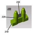
도 1은 본 발명인 블라인드 작동줄용 안전장치의 외부 구조를 보여주는 도면,
도 2는 본 발명인 블라인드 작동줄용 안전장치의 내부 구조를 보여주는 도면,
도 3은 본 발명인 블라인드 작동줄용 안전장치에 적용되는 이동구, 절단구 및 작동줄이 설치된 상태를 보여주는 도면,
도 4는 본 발명인 블라인드 작동줄용 안전장치에 적용되는 이동구의 구조를 보여주는 도면,
도 5 및 도 6은 본 발명인 블라인드 작동줄용 안전장치에 적용되는 절단구의 구조를 보여주는 도면,
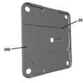
도 7은 본 발명인 블라인드 작동줄용 안전장치에 적용되는 케이스의 구조를 보여주는 도면,
도 8은 본 발명인 블라인드 작동줄용 안전장치에 적용되는 커버의 구조를 보여주는 도면.1 is a view showing the external structure of the safety device for the blind operating line of the present invention,
2 is a view showing the internal structure of the safety device for the blind operating line of the present invention,
Figure 3 is a view showing a state in which the moving tool, the cutting tool and the operating line is applied to the safety device for the blind operating line of the present invention,
Figure 4 is a view showing the structure of a mobile device applied to the safety device for the blind operating line of the present invention,
5 and 6 is a view showing the structure of a cutting tool applied to the safety device for the blind operating line of the present invention,
7 is a view showing the structure of the case applied to the safety device for the blind operating line of the present invention,
8 is a view showing the structure of the cover applied to the safety device for the blind operating line of the present invention.
본 발명에서는 종래 안전장치가 마련되지 않은 블라인드에도 손쉽게 채용할 수 있어 안전사고를 미연에 방지할 수 있도록 볼체인 형태를 이루며 블라인드를 개폐하는 작동줄이 상하방향으로 관통하는 케이스를 포함하되, 상기 케이스의 내부에는 탄성에 의해 작동줄을 밀어 작동줄이 일측으로 치우쳐 지나도록 하는 이동구와, 상기 이동구에 의해 케이스 내에서 작동줄이 지나는 지점보다 내측으로 고정된 칼날이 구비되어, 상기 작동줄이 이동구에 작용하는 탄성력보다 큰 힘으로 당겨지는 경우 칼날에 의해 끊어지는 것을 특징으로 하는 블라인드 작동줄용 안전장치를 제안한다.In the present invention, the conventional safety device can be easily adopted even for blinds that do not have a ball chain shape to prevent safety accidents in advance, and include a case in which the operation line for opening and closing the blind penetrates in the vertical direction. The inside of the inside is provided with a moving tool that pushes the working string by elasticity so that the working string is biased to one side, and a blade fixed inward than the point at which the working string passes in the case by the moving port, so that the working string is moved. A safety device for a blind operating line is proposed, characterized in that it is cut by a blade when pulled with a force greater than the elastic force acting on the sphere.
본 발명의 권리범위는 이하에서 설명하는 실시예에 한정되는 것은 아니며, 본 발명의 기술적 요지를 벗어나지 않는 범위 내에서 당해 기술분야의 통상적인 지식을 가진자에 의하여 다양하게 변형 실시될 수 있다.The scope of the present invention is not limited to the embodiments described below, and can be variously modified by those skilled in the art without departing from the technical gist of the present invention.
이하, 본 발명인 블라인드 작동줄용 안전장치는 첨부된 도 1 내지 도 8을 참고로 상세하게 설명한다.Hereinafter, the safety device for the blind operation line according to the present invention will be described in detail with reference to FIGS. 1 to 8.
본 발명인 블라인드 작동줄용 안전장치는 도 1 및 도 2에 도시된 바와 같이 작동줄(10)이 상하방향으로 관통하는 케이스(A)를 포함한다.The safety device for the blind operation line of the present invention includes a case (A) through which the
상기 작동줄(10)은 일 예로, 블라인드를 상하 또는 좌우 방향으로 개폐하기 위해 천정 등에 설치되는 블라인드본체에 구비된 스프로켓(sprocket) 등과 같은 구성에 일측이 감겨 하방으로 쳐지도록 구비되며, 본 발명에서의 작동줄(10)은 종래 안전장치가 구비되어 있지 않은 블라인드의 작동줄로 대체될 수 있다.The
그리고, 상기 작동줄(10)은 폐곡선을 이루는 줄만으로 이루어질 수 있으나, 도면에 도시된 바와 같이 폐곡선을 이루는 줄에 다수의 볼이 구비된 볼체인 형태를 이룸이 바람직하며, 볼체인 형태를 이룰 경우 볼 간의 간격은 일정하게 형성됨이 보다 바람직하다. 또한, 본 발명에서의 작동줄(10)은 폐곡선을 이룰 때 동일 높이에 위치하는 2개의 줄 중에서 어느 하나를 의미한다.In addition, the
상기 케이스(300)는 내부가 빈 몸체를 이루며, 볼체인 형태를 이루며 블라인드를 개폐하는 작동줄(10)이 상하방향으로 관통한다. 또한, 상기 케이스(A)의 내부에는 이동구(100)와 칼날(230)이 구비된다.The
구체적으로 살펴보면, 상기 이동구(100)는 도 2에 도시된 바와 같이 케이스(A)의 내부에서 탄성에 의해 작동줄(10)을 밀어 작동물(10)이 케이스(A) 내부 일측으로 치우쳐 지나도록 한다. 따라서, 도면에는 도시되지 않았으나, 상기 이동구(100)의 타측과 케이스(A)의 내부 타측에는 스프링이 구비되어 이동구(100)에 탄성을 부여할 수 있으며, 상기 스프링은 이동구(100)의 타측과 케이스(A)의 내부 타측에 돌출형성된 끼움돌기(30)에 끼워져 고정될 수 있다.Specifically, as shown in FIG. 2, the
상기 칼날(230)은 도 2 및 도 3에 도시된 바와 같이 상기 이동구(100)에 의해 케이스(A) 내에서 작동줄(10)이 지나는 지점보다 내측으로 고정된다. 이에 따라, 상기 작동줄(10)이 평소 이동구(100)에 작용하는 탄성력보다 큰 힘으로 당겨지는 경우, 상기 이동구(100)는 타측을 향해 이동하게 되며, 이로 인해 이동구(100)에 의해 밀려있던 작동줄(10) 또한 타측으로 이동하게 되는바, 칼날(230)에 의해 작동줄(10)이 끊어지게 된다.The
상기와 같은 동작이 용이하게 이루어질 수 있도록 상기 이동구(100)는 도 2에 도시된 바와 같이 케이스(A)의 내측 중앙부에 구비되어 중앙부의 일측과 타측으로 이동가능함이 바람직하며, 이동구(100)가 안정적으로 중앙부의 일측과 타측으로 이동할 수 있도록 상기 이동구(100)가 맞닿는 케이스(A)의 일면과 타면에는 이동구(100)의 폭과 대응되는 위치에 가이드턱(20)이 형성될 수 있다.In order to facilitate the above-described operation, the moving
상기 가이드턱(20)에 의해 이동구(100)의 상측과 하측이 감싸진 형태를 이루게 되는바, 상기 이동구(100)는 이동하여야 하는 라인으로부터 이탈되지 않고 안정적으로 이동할 수 있게 된다.Since the upper and lower sides of the moving
또한, 상기 칼날(230)은 이동구(100)가 타측으로 이동될 수 있는 범위를 고려하였을 때, 상기 케이스(A)의 중심에서 약간 일측으로 치우진 지점에 구비됨이 바람직하다.In addition, considering the range in which the
상기에서 설명한 바와 같이 작동줄(10)에 목 등이 걸려 작동줄(10)이 과동한 힘으로 당겨지는 경우, 이동구(100)에 이동에 따라 칼날(230)이 작동줄(10)을 끊게 되므로, 작동줄(10)에 의해 다치거나 사망하는 안전사고를 방지할 수 있으며, 안전장치가 마련되지 않은 블라인드에 구비된 작동줄(10)에도 손쉽게 설치할 수 있으므로 안전성을 확보할 수 있다.As described above, when the
한편, 상기 이동구(100)는 도 3 및 도 4에 도시된 바와 같이 일측으로부터 타측을 향해 함입형성된 수용홈(110)이 형성될 수 있으며, 상기 칼날(230)은 수용홈(110)의 내측에 위치하도록 고정될 수 있다. 이때, 상기 수용홈(110)은 폭이 작동줄(10)을 이루는 다수의 볼 간의 간격보다 작게 형성되어, 칼날(230)이 위치하는 수용홈(110)의 내측으로 볼이 들어갈 수 없는 구조를 형성하여 과도한 힘이 작용하는 경우 수용홈(110)에 볼이 들어감으로써 작동줄(10)이 끊어지지 않는 것을 방지할 수 있다.Meanwhile, as shown in FIGS. 3 and 4, the
또한, 상기 수용홈(110)의 내측에 위치하는 칼날(230)은 도 3에 도시된 바와 같이 작동줄(10)과 직교하는 방향으로 설치되어, 이동구(100)가 타측으로 이동될 경우 작동줄(10)이 용이하게 끊어지도록 함이 바람직하다.In addition, the
그리고, 상기 케이스(A)는 도 2에 도시된 바와 같이 상하방향으로 개방된 내벽이 내부에 형성될 수 있는데, 상기 내벽은 작동줄(10)에 구비된 볼이 내벽에 걸리지 않으면서 용이하게 이동될 수 있도록 원형으로 형성됨이 바람직하다. 이때, 상기 이동구(100)의 일측부는 도 2 및 도 4에 도시된 바와 같이 인접한 내벽에 대응되는 형태, 즉 인접한 내벽에 대응되는 호 형태를 이루면서 내측으로 함입된 가이드홈(120)이 형성될 수 있다.And, in the case (A), as shown in Figure 2, the inner wall opened in the vertical direction may be formed therein, the inner wall is easily moved without the ball provided on the
이에 따라, 상기 작동줄(10)은 케이스(A) 내에서 이동구(100)와 맞닿지 않는 지점에서는 케이스(A)의 내벽에 의해 가이드되고, 이동구(100)와 맞닿는 지점에서는 케이스(A)의 내벽과 가이드홈(120)에 의해 가이드된다. 즉, 케이스(A) 내에서 작동줄(10)에 구비된 볼이 맞닿는 부분 모두가 곡선 형태를 이루고 있는바, 작동줄(10)이 케이스(A) 내에서도 용이하게 움직일 수 있게 된다.Accordingly, the
한편, 상기 칼날(230)은 독립적으로 케이스(A)에 고정된 형태를 이룰 수 있음은 물론, 도 3 및 도 5에 도시된 바와 같이 절단구(200)에 설치될 수 있다. 보다 구체적으로, 상기 절단구(200)는 도 5 및 도 6에 도시된 바와 같이 바(bar) 형태로 형성되어 작동줄(10)과 직교하도록 상기 수용홈(110)의 내측에 위치하며 중앙부에 상방으로 칼날(230)이 설치되는 고정바(210)를 포함할 수 있다. 따라서, 상기 고정바(210)의 중앙부에는 도 6에 도시된 바와 같이 칼날(230)이 꽂혀 고정되기 위한 홈이 형성될 수 있다.On the other hand, the
또한, 상기 칼날(230)이 설치된 고정바(210)는 도 3에 도시된 바와 같이 이동구(100)의 양방향으로 돌출되도록 형성될 수 있으며, 고정바(210)의 돌출된 일단과 타단은 도 1에 도시된 바와 같이 케이스(A)에 끼워져 상기 칼날(230)이 견고히 고정되도록 할 수 있다.In addition, the fixing
그리고, 상기 절단구(200)는 도 5에 도시된 바와 같이 칼날(230)의 양측을 감싸면서 상방으로 형성된 유도봉(220)을 더 포함할 수 있으며, 이에 따라 상기 유도봉(220)에는 도 6에 도시된 바와 같이 내측을 향해 칼날(230)의 양측이 끼워지기 위한 설치홈이 형성될 수 있다. 또한, 상기 유도봉(220)은 도 2에 도시된 바와 같이 칼날(230)보다는 길게 형성되되, 상기 이동구(100)의 내측, 즉 수용홈(110) 내에 위치할 정도의 길이를 가진다. 이는 평소 유도봉(220)으로 인해 작동줄(10)의 이동이 간섭되지 않도록 하기 위함이다.In addition, the
또한, 상기 유도봉(220)은 도 5 및 도 6에 도시된 바와 같이 칼날(230)의 상측으로 원추형을 이루도록 형성됨이 바람직하다. 상기 작동줄(10)에 과도한 힘이 작용하여 상기 이동구(100)가 이동되는 경우, 작동줄(10)에서 칼날(230)에 의해 끊어져야 되는 지점의 상하방향으로 위치하는 볼이 유도봉(220)에서 원추형을 이루는 부분을 따라 용이하게 이동되는바, 유도봉(220)을 따라 이동된 볼과 볼 사이의 지점에 해당되는 작동줄(10)이 칼날(230)에 의해 끊어지게 된다.In addition, the
한편, 본 발명인 블라인드 작동줄용 안전장치에 적용되는 케이스(A)는 도 2 및 도 7에 도시된 바와 같이 전면(前面)이 개방되도록 형성될 수 있으며, 이 경우 도 8에 도시된 바와 같이 상기 케이스(A)의 전면(前面)을 밀폐시키는 커버(300)가 더 구비될 수 있다. 상기 커버(300)가 더 구비되는 경우 앞서 설명한 가이드턱(20)은 상기 케이스(A)와 커버(300)에서 이동구(100)가 맞닿는 지점에 모두 형성됨이 바람직하다. 또한, 상기 고정바(210)의 돌출된 일단과 타단이 끼워지기 위한 관통된 홀이 케이스(A)와 커버(300)에 형성될 수 있다.On the other hand, the case (A) applied to the safety device for the blind operating line of the present invention can be formed to open the front (front) as shown in Figures 2 and 7, in this case the case as shown in Figure 8 A
A : 케이스
10 : 작동줄20 : 가이드턱
100 : 이동구110 : 수용홈
120 : 가이드홈
200 : 절단구210 : 고정바
220 : 유도봉230 : 칼날
300 : 커버A: Case
10: operation line 20: guide jaw
100: moving port 110: receiving home
120: guide home
200: cutting tool 210: fixing bar
220: guide rod 230: blade
300: cover
Claims (5)
Translated fromKorean상기 케이스(A)의 내부에는 탄성에 의해 작동줄(10)을 밀어 작동줄(10)이 일측으로 치우쳐 지나도록 하는 이동구(100)와, 상기 이동구(100)에 의해 케이스(A) 내에서 작동줄(10)이 지나는 지점보다 내측으로 고정된 칼날(230)이 구비되어,
상기 작동줄(10)이 이동구(100)에 작용하는 탄성력보다 큰 힘으로 당겨지는 경우 칼날(230)에 의해 끊어지는 것을 특징으로 하는 블라인드 작동줄용 안전장치.In the form of a ball chain, including a case (A) through which the operation line (10) for opening and closing the blind penetrates in the vertical direction,
The inside of the case (A) by moving the operating string (10) by elasticity to move the operating string (10) biased to one side, and the moving port (100) in the case (A) In operation line 10 is provided with a blade 230 fixed inward than the point where the pass,
When the operation line 10 is pulled with a force greater than the elastic force acting on the moving tool 100, a safety device for a blind operation line characterized in that it is cut off by a blade 230.
상기 이동구(100)는 일측으로부터 타측을 향해 함입형성된 수용홈(110)이 형성되고, 상기 칼날(230)은 수용홈(110) 내측에 위치하도록 고정되되,
상기 수용홈(110)은 폭이 작동줄(10)을 이루는 다수의 볼 간의 간격보다 작게 형성되고, 상기 칼날(230)은 작동줄(10)과 직교하는 방향으로 설치되는 것을 특징으로 하는 블라인드 작동줄용 안전장치.According to claim 1,
The moving tool 100 is formed with a receiving groove 110 is formed indented from one side to the other side, the blade 230 is fixed to be located inside the receiving groove 110,
The receiving groove 110 is formed smaller than the gap between the plurality of balls forming the operation line 10, the blade 230 is blind operation, characterized in that installed in a direction orthogonal to the operation line (10) Safety device for files.
상기 케이스(A)는 바(bar) 형태로 형성되어 작동줄(10)과 직교하도록 상기 수용홈(110)의 내측에 위치하며 중앙부에 상방으로 칼날(230)이 설치되는 고정바(210)를 포함하는 절단구(200)가 더 구비되되,
상기 고정바(210)는 이동구(100)의 양방향으로 돌출되어 일단과 타단이 케이스(A)에 끼워져 고정되는 것을 특징으로 하는 블라인드 작동줄용 안전장치.According to claim 2,
The case (A) is formed in the form of a bar (bar) is located on the inside of the receiving groove 110 to be orthogonal to the operation line 10 and the fixed bar 210, the blade 230 is installed upward in the center portion The cutting tool 200 is further provided,
The fixing bar 210 is protruded in both directions of the moving tool 100, one end and the other end is fitted to the case (A) is secured for the blind operating line.
상기 절단구(200)는 칼날(230)의 양측을 감싸면서 상방으로 형성된 유도봉(220)을 더 포함하되,
상기 유도봉(220)은 칼날(230)보다 길면서 끝단이 이동구(100)의 내측에 위치하도록 형성되고, 칼날(230)의 상측으로 원추형을 이루는 것을 특징으로 하는 블라인드 작동줄용 안전장치.According to claim 3,
The cutting tool 200 further includes a guide rod 220 formed upward while surrounding both sides of the blade 230,
The guide rod 220 is longer than the blade 230, the end is formed so as to be located inside the moving tool 100, a safety device for a blind operating line, characterized in that conical to the upper side of the blade 230.
상기 케이스(A)는 상하방향으로 개방된 원형의 내벽이 내부에 형성되고,
상기 이동구(100)의 일측부는 인접한 내벽에 대응되는 형태를 이루면서 내측으로 함입된 가이드홈(120)이 형성되어, 상기 작동줄(10)이 케이스(A)의 내벽과 가이드홈(120)를 따라 용이하게 작동되는 것을 특징으로 하는 불라인드 작동줄용 안전장치.According to claim 1,
In the case (A), a circular inner wall open in the vertical direction is formed therein,
One side of the moving port 100 is formed in the guide groove 120 is formed inwardly corresponding to the adjacent inner wall, the operation line 10 is the inner wall of the case (A) and the guide groove 120 Safety device for a blind operating line characterized in that it is easily operated according to.
Priority Applications (1)
| Application Number | Priority Date | Filing Date | Title |
|---|---|---|---|
| KR1020180118741AKR102121668B1 (en) | 2018-10-05 | 2018-10-05 | Safety apparatus for blind line |
Applications Claiming Priority (1)
| Application Number | Priority Date | Filing Date | Title |
|---|---|---|---|
| KR1020180118741AKR102121668B1 (en) | 2018-10-05 | 2018-10-05 | Safety apparatus for blind line |
Publications (2)
| Publication Number | Publication Date |
|---|---|
| KR20200039171Atrue KR20200039171A (en) | 2020-04-16 |
| KR102121668B1 KR102121668B1 (en) | 2020-06-10 |
Family
ID=70454631
Family Applications (1)
| Application Number | Title | Priority Date | Filing Date |
|---|---|---|---|
| KR1020180118741AExpired - Fee RelatedKR102121668B1 (en) | 2018-10-05 | 2018-10-05 | Safety apparatus for blind line |
Country Status (1)
| Country | Link |
|---|---|
| KR (1) | KR102121668B1 (en) |
Citations (2)
| Publication number | Priority date | Publication date | Assignee | Title |
|---|---|---|---|---|
| US5553650A (en)* | 1994-08-19 | 1996-09-10 | Verosol Usa Inc. | Child safety device for looped cords |
| WO2004094759A1 (en)* | 2003-04-24 | 2004-11-04 | Verosol Nederland B.V. | Cord safety device |
- 2018
- 2018-10-05KRKR1020180118741Apatent/KR102121668B1/ennot_activeExpired - Fee Related
Patent Citations (2)
| Publication number | Priority date | Publication date | Assignee | Title |
|---|---|---|---|---|
| US5553650A (en)* | 1994-08-19 | 1996-09-10 | Verosol Usa Inc. | Child safety device for looped cords |
| WO2004094759A1 (en)* | 2003-04-24 | 2004-11-04 | Verosol Nederland B.V. | Cord safety device |
Also Published As
| Publication number | Publication date |
|---|---|
| KR102121668B1 (en) | 2020-06-10 |
Similar Documents
| Publication | Publication Date | Title |
|---|---|---|
| CA2747919C (en) | Cord lock guide for blinds | |
| US7841376B2 (en) | Window covering safety device | |
| CN204580840U (en) | Curtain rolling rope structure | |
| US9157274B2 (en) | Window covering | |
| US7117920B2 (en) | Automatically activated cord lock | |
| US20130091968A1 (en) | Tension device for looped-cord system | |
| KR102081994B1 (en) | Fire shutter | |
| CA2878553A1 (en) | Device for controlling the actuation of a group for moving a curtain/awning | |
| KR101732420B1 (en) | Apparatus for preventing a finger from inserting in a door of elevator | |
| KR101990204B1 (en) | Damping Apparatus for Sliding Door | |
| KR102121668B1 (en) | Safety apparatus for blind line | |
| WO2011004199A2 (en) | Anti ligature device | |
| US10584529B2 (en) | Safety device for a chain of a shade | |
| KR20190099873A (en) | Stopper for insect screen and window having the same | |
| KR101562372B1 (en) | Blind Wire Holder | |
| KR102033553B1 (en) | A device to prevent the screen from coming off | |
| KR101877329B1 (en) | Guide apparatus for preventing fall of mosquito net | |
| KR101661459B1 (en) | Horizontal sliding door | |
| KR101328268B1 (en) | Take up mosquito net | |
| KR200389361Y1 (en) | Roll type Mosquito Net | |
| KR101601139B1 (en) | Safety bar for string of blind | |
| KR101608150B1 (en) | Honeycomb Blinds | |
| KR102083057B1 (en) | Self-closing device for sliding window | |
| KR200372370Y1 (en) | Anti-separating device of a window from the window frame, and a window frame using it | |
| KR101323676B1 (en) | Lower end bar of roll screen having the cushion function, the lower end bar cap and roll screen using these |
Legal Events
| Date | Code | Title | Description |
|---|---|---|---|
| PA0109 | Patent application | St.27 status event code:A-0-1-A10-A12-nap-PA0109 | |
| PA0201 | Request for examination | St.27 status event code:A-1-2-D10-D11-exm-PA0201 | |
| D13-X000 | Search requested | St.27 status event code:A-1-2-D10-D13-srh-X000 | |
| D14-X000 | Search report completed | St.27 status event code:A-1-2-D10-D14-srh-X000 | |
| PE0902 | Notice of grounds for rejection | St.27 status event code:A-1-2-D10-D21-exm-PE0902 | |
| T11-X000 | Administrative time limit extension requested | St.27 status event code:U-3-3-T10-T11-oth-X000 | |
| E13-X000 | Pre-grant limitation requested | St.27 status event code:A-2-3-E10-E13-lim-X000 | |
| P11-X000 | Amendment of application requested | St.27 status event code:A-2-2-P10-P11-nap-X000 | |
| P13-X000 | Application amended | St.27 status event code:A-2-2-P10-P13-nap-X000 | |
| E701 | Decision to grant or registration of patent right | ||
| PE0701 | Decision of registration | St.27 status event code:A-1-2-D10-D22-exm-PE0701 | |
| PG1501 | Laying open of application | St.27 status event code:A-1-1-Q10-Q12-nap-PG1501 | |
| GRNT | Written decision to grant | ||
| PR0701 | Registration of establishment | St.27 status event code:A-2-4-F10-F11-exm-PR0701 | |
| PR1002 | Payment of registration fee | St.27 status event code:A-2-2-U10-U11-oth-PR1002 Fee payment year number:1 | |
| PG1601 | Publication of registration | St.27 status event code:A-4-4-Q10-Q13-nap-PG1601 | |
| R18-X000 | Changes to party contact information recorded | St.27 status event code:A-5-5-R10-R18-oth-X000 | |
| PC1903 | Unpaid annual fee | St.27 status event code:A-4-4-U10-U13-oth-PC1903 Not in force date:20230605 Payment event data comment text:Termination Category : DEFAULT_OF_REGISTRATION_FEE | |
| PC1903 | Unpaid annual fee | St.27 status event code:N-4-6-H10-H13-oth-PC1903 Ip right cessation event data comment text:Termination Category : DEFAULT_OF_REGISTRATION_FEE Not in force date:20230605 |