KR20200037144A - Tonsil surgery aspiration ablation apparatus - Google Patents
Tonsil surgery aspiration ablation apparatusDownload PDFInfo
- Publication number
- KR20200037144A KR20200037144AKR1020197038108AKR20197038108AKR20200037144AKR 20200037144 AKR20200037144 AKR 20200037144AKR 1020197038108 AKR1020197038108 AKR 1020197038108AKR 20197038108 AKR20197038108 AKR 20197038108AKR 20200037144 AKR20200037144 AKR 20200037144A
- Authority
- KR
- South Korea
- Prior art keywords
- tonsil
- blade member
- cutting blade
- ablation apparatus
- aspiration
- Prior art date
- Legal status (The legal status is an assumption and is not a legal conclusion. Google has not performed a legal analysis and makes no representation as to the accuracy of the status listed.)
- Ceased
Links
- 210000002741palatine tonsilAnatomy0.000titleclaimsabstractdescription67
- 238000002679ablationMethods0.000titleclaimsabstractdescription51
- 238000001356surgical procedureMethods0.000titleclaimsdescription10
- 230000007246mechanismEffects0.000claimsabstractdescription20
- 238000000034methodMethods0.000claimsdescription11
- 238000002271resectionMethods0.000claimsdescription10
- 239000012530fluidSubstances0.000abstractdescription6
- 210000001519tissueAnatomy0.000description8
- 210000003813thumbAnatomy0.000description6
- 239000008280bloodSubstances0.000description5
- 210000004369bloodAnatomy0.000description5
- 230000000740bleeding effectEffects0.000description4
- 210000003811fingerAnatomy0.000description3
- 230000015271coagulationEffects0.000description2
- 238000005345coagulationMethods0.000description2
- 230000007423decreaseEffects0.000description2
- 210000004247handAnatomy0.000description2
- 230000004048modificationEffects0.000description2
- 238000012986modificationMethods0.000description2
- 210000003800pharynxAnatomy0.000description2
- 230000000717retained effectEffects0.000description2
- 231100000241scarToxicity0.000description2
- 208000032544CicatrixDiseases0.000description1
- 208000007536ThrombosisDiseases0.000description1
- 230000009471actionEffects0.000description1
- 230000023555blood coagulationEffects0.000description1
- 230000008859changeEffects0.000description1
- 230000009977dual effectEffects0.000description1
- 230000005611electricityEffects0.000description1
- 208000014674injuryDiseases0.000description1
- 239000002184metalSubstances0.000description1
- 230000008569processEffects0.000description1
- 238000011084recoveryMethods0.000description1
- 210000003296salivaAnatomy0.000description1
- 230000037387scarsEffects0.000description1
- 238000007483tonsillectomyMethods0.000description1
- 230000007704transitionEffects0.000description1
- 230000008733traumaEffects0.000description1
Images


Classifications
- A—HUMAN NECESSITIES
- A61—MEDICAL OR VETERINARY SCIENCE; HYGIENE
- A61B—DIAGNOSIS; SURGERY; IDENTIFICATION
- A61B17/00—Surgical instruments, devices or methods
- A61B17/24—Surgical instruments, devices or methods for use in the oral cavity, larynx, bronchial passages or nose; Tongue scrapers
- A61B17/26—Tonsillotomes, with or without means for stopping bleeding
- A—HUMAN NECESSITIES
- A61—MEDICAL OR VETERINARY SCIENCE; HYGIENE
- A61B—DIAGNOSIS; SURGERY; IDENTIFICATION
- A61B17/00—Surgical instruments, devices or methods
- A61B17/32—Surgical cutting instruments
- A61B17/3205—Excision instruments
- A—HUMAN NECESSITIES
- A61—MEDICAL OR VETERINARY SCIENCE; HYGIENE
- A61B—DIAGNOSIS; SURGERY; IDENTIFICATION
- A61B17/00—Surgical instruments, devices or methods
- A61B17/30—Surgical pincettes, i.e. surgical tweezers without pivotal connections
- A61B2017/306—Surgical pincettes, i.e. surgical tweezers without pivotal connections holding by means of suction
- A—HUMAN NECESSITIES
- A61—MEDICAL OR VETERINARY SCIENCE; HYGIENE
- A61B—DIAGNOSIS; SURGERY; IDENTIFICATION
- A61B17/00—Surgical instruments, devices or methods
- A61B17/32—Surgical cutting instruments
- A61B17/3209—Incision instruments
- A61B17/3211—Surgical scalpels, knives; Accessories therefor
- A61B2017/32113—Surgical scalpels, knives; Accessories therefor with extendable or retractable guard or blade
- A—HUMAN NECESSITIES
- A61—MEDICAL OR VETERINARY SCIENCE; HYGIENE
- A61B—DIAGNOSIS; SURGERY; IDENTIFICATION
- A61B2217/00—General characteristics of surgical instruments
- A61B2217/002—Auxiliary appliance
- A61B2217/005—Auxiliary appliance with suction drainage system
Landscapes
- Health & Medical Sciences (AREA)
- Surgery (AREA)
- Life Sciences & Earth Sciences (AREA)
- General Health & Medical Sciences (AREA)
- Public Health (AREA)
- Veterinary Medicine (AREA)
- Nuclear Medicine, Radiotherapy & Molecular Imaging (AREA)
- Animal Behavior & Ethology (AREA)
- Molecular Biology (AREA)
- Engineering & Computer Science (AREA)
- Biomedical Technology (AREA)
- Heart & Thoracic Surgery (AREA)
- Medical Informatics (AREA)
- Dentistry (AREA)
- Oral & Maxillofacial Surgery (AREA)
- Hematology (AREA)
- Otolaryngology (AREA)
- Pulmonology (AREA)
- Surgical Instruments (AREA)
- Media Introduction/Drainage Providing Device (AREA)
Abstract
Translated fromKoreanDescription
Translated fromKorean본 발명은 일반적으로 편도선 수술 기구에 관한 것이다. 보다 구체적으로는, 본 발명은 절제 및 흡인 모드와 오직 흡인 모드 사이에서 선택적으로 사용하도록 작동가능한 편도선 수술 기구에 관한 것이다.The present invention relates generally to tonsil surgical instruments. More specifically, the present invention relates to tonsil surgical instruments operable to selectively use between resection and aspiration modes and only aspiration mode.
편도선 수술은 구개편도(palatine tonsil)가 편도와(tonsillar fossa)와 지칭되는 인두의 측면에서 리세스(recess)로부터 제거되는 수술 방법이다.Tonsil surgery is a surgical method in which the palatine tonsil is removed from the recess in terms of the pharynx referred to as the tonsillar fossa.
이러한 편도선 수술 방법 중 한 타입의 수술은 편도선을 절제하기 위하여, 통상 한 손으로 편도선을 고정시키고 또 다른 손으로는 편도선을 고정하기 위한 겸자(forcep)를 사용하면서, 기다란 절단 블레이드를 사용하는 방법을 포함한다.One of these tonsil surgery methods is a method of using an elongated cutting blade while using a forceps to fix the tonsil with one hand and fix the tonsil with the other hand, in order to excise the tonsil. Includes.
수술 동안, 유체(혈액 및 침)을 제거하기 위하여, 진공 흡인 끝단이 사용될 수 있다. 양커 끝단(Yankauer tip)(편도선 끝단)은 가장 일반적으로 사용되는 흡인 끝단 중 하나이다.During surgery, a vacuum suction end can be used to remove fluid (blood and saliva). The Yanker tip (one tonsil tip) is one of the most commonly used suction tips.
하지만, 세 가지 기구를 사용하는 것은, 필요 시에 기구 조작을 보조한다거나 대안으로 기구를 교체해야 하는 과정을 필요로 하여, 복잡하고 수술 시간이 길어진다.However, the use of the three instruments is complex and lengthy of surgery, requiring the need to replace the instrument as an alternative to assist in manipulating the instrument if necessary.
게다가, 양커 끝단이 많은 양의 유체를 흡인할 수 있지만, 양커 끝단은 끝단이 커다란 혈액 응고물질 또는 조직들에 가까이 위치될 때 쉽게 막히는 단점을 가진다. 수술의사는 종종 끝단에 거즈 스펀지를 배열하여 응고물질이 막히는 것을 방지하기 위하여 거즈를 통해 유체를 흡인한다.In addition, although the Yanker end can aspirate large amounts of fluid, the Yanker end has the disadvantage of being easily clogged when the end is positioned close to a large blood clot or tissue. Surgeons often arrange gauze sponges at the ends to aspirate the fluid through the gauze to prevent clogging.
본 발명은 종래 기술의 단점들 중 몇몇 단점을 해결하고 대안예를 제공하기 위해 편도선 수술 흡인 절제 기구를 제공하는 데 그 목적이 있다.The present invention aims to solve some of the shortcomings of the prior art and to provide a tonsil surgical aspiration ablation apparatus to provide an alternative.
종래 기술의 정보가 본 명세서에서 참조문헌으로 언급되지만, 이러한 참조문헌은 통상적인 일반적 기술로 이해해서는 안 된다.Although prior art information is referred to herein as references, these references should not be understood as conventional general techniques.
본 발명은 근위 핸들(proximal handle) 및 원위 곡선형 끝단(distal curved tip)을 포함하는 편도선 수술 흡인 절제 기구(tonsillectomy suction dissector)에 관한 것이다. 상기 기구는 유체를 흡인하기 위하여 상기 끝단 내에서 끝단을 따라 끝단의 단부에 위치된 하나 이상의 흡인 입구 포트(suction inlet port)를 핸들에서 진공 포트(vacuum port)에 작동 가능하게 연결하는 흡인 채널(suction channel)을 포함한다. 또한, 기구는 슬롯 내에 슬라이딩 이동 가능하게 보유되며 상기 끝단을 따라 상응하는 슬롯 내에서 폭방향 및 길이방향으로 배열되는 가요성 절단 블레이드 부재를 추가로 포함하되, 상기 가요성 절단 블레이드 부재는, 손으로 작동가능한 잠금 메커니즘(locking mechanism)에 의해, 가요성 절단 블레이드 부재의 원위 절단 단부(distal cutting end)가 끝단의 단부로부터 연장되는 연장된 위치(extended position)와 가요성 절단 블레이드 부재의 원위 절단 단부가 끝단의 단부 내로 철회되는 철회된 위치(retracted position) 사이에서 작동될 수 있도록 구성된다.The present invention relates to a tonsillectomy suction dissector comprising a proximal handle and a distal curved tip. The mechanism is capable of operatively connecting one or more suction inlet ports located at the ends of the ends along the ends within the ends to aspirate the fluid from the handle to a vacuum port. channel). In addition, the mechanism further includes a flexible cutting blade member slidably held in the slot and arranged in the width and length directions in the corresponding slot along the end, wherein the flexible cutting blade member is by hand By an operable locking mechanism, an extended position in which the distal cutting end of the flexible cutting blade member extends from the end of the end and a distal cutting end of the flexible cutting blade member It is configured to be operable between retracted positions that are retracted into the ends of the ends.
이렇게 블레이드가 연장되고 철회되면, 흡인 끝단(suction tip) 또는 흡인 절제 기구로서 이중 기능(dual functionality)을 수행할 수 있으며, 그에 따라 수술 속도가 증가되고 혈액 손실이 줄어든다.When the blade is extended and retracted in this way, it is possible to perform dual functionality as a suction tip or a suction ablation device, thereby increasing the surgical speed and reducing blood loss.
그에 따라, 잠금 메커니즘은 상기 절제 기구를 수술 시에 절제 및 흡인 모드와 오직 흡인 모드 사이에서 신속하게 변환하기 위해 사용될 수 있다. 게다가, 이러한 형상으로 인해, 한 손으로는 절제 및 흡입 과정을 수행하면서, 다른 손으로는 다른 임무, 가령, 겸자를 조작할 수 있다.Accordingly, a locking mechanism can be used to rapidly convert the ablation apparatus between the ablation and aspiration mode and only the aspiration mode during surgery. In addition, due to this shape, the ablation and inhalation processes can be performed with one hand while manipulating other tasks, such as forceps, with the other.
또한, 상기 잠금 메커니즘은, 핸들을 쥐기 위하여, 검지손가락을 사용하지 않고서도, 한 손으로, 가령, 오직 엄지손가락 만을 사용하여, 기구를 변환시킬 수도 있다.In addition, the locking mechanism can also be used to change the mechanism with one hand, for example, only the thumb, without using the index finger to hold the handle.
특히, 잠금 메커니즘은 핸들의 상측 구멍(superior aperture)들 내에 고정된 잠금 레버(locking lever)를 포함하는 가요성 절단 블레이드 부재를 포함할 수 있다. 절단 블레이드 부재는 잠금 레버가 상측 구멍들 내에 고정되는 연장된 위치로 전방으로 밀기 위해 핸들의 후방 구멍으로부터 연장된다. 게다가, 잠금 레버는 절단 블레이드 부재를 철회하기 위해 레버를 후방으로 끌어당기고 연결을 분리하기 위해 상측 구멍들을 통해 접근 가능하다.In particular, the locking mechanism can include a flexible cutting blade member that includes a locking lever secured in the upper apertures of the handle. The cutting blade member extends from the rear hole of the handle to push forward to the extended position where the locking lever is fixed in the upper holes. In addition, the locking lever is accessible through the upper holes to pull the lever back to withdraw the cutting blade member and disconnect the connection.
출혈이 발생되는, 편도와를 향한 흡인 홀(suction hole)의 위치는, 정확한 출혈 지점에서, 혈액을 즉각적으로 흡입할 수 있으며, 그에 따라 목구멍에 혈액이 축적되는 가능성을 최소화시켜, 혈액/응고물질이 흡입되는 위험을 줄일 수 있다.The location of the suction hole toward the tonsil, where bleeding occurs, can immediately inhale the blood at the correct bleeding point, thereby minimizing the possibility of blood accumulating in the throat, resulting in blood / coagulation It can reduce the risk of being inhaled.
또한, 블레이드가 수술의사를 향하도록 위치되면, 정확하게 절제할 수 있을 뿐만 아니라 항상 절단 부위를 완전히 볼 수 있게 하여, 의도치 않게 주변 조직(surrounding tissue)을 손상시켜 추가적으로 출혈을 발생시킬 수 있는 가능성이 줄어든다.In addition, when the blade is positioned to face the surgeon, not only can it be accurately excised, but it also allows the cutting site to be completely visible at all times, thereby potentially inadvertently damaging surrounding tissue and causing further bleeding Decreases.
게다가, 흡인 입구 포트의 형상(configuration)으로 인해, 양커 끝단(Yankauer tip)에 의해 제공될 수 있는 것과 같이 폐색(occlusion) 문제를 실질적으로 줄이거나 제거할 수 있다. 특히, 흡인 입구 포트는 원위 절단 단부에 대해 하측에 위치될 수 있고, 끝단의 상이한 면(face)들에 배열될 수 있으며, 한 단부 표면에 대해 누름으로써 폐색을 방지할 수 있다. 특히, 다수의 실시예들에서, 흡인 입구 포트는 한 쌍의 원위 방향으로 위치되고, 횡방향으로 맞은편에 위치되며, 하측에 위치된 흡인 입구 포트를 포함할 수 있다.In addition, due to the configuration of the suction inlet port, occlusion problems can be substantially reduced or eliminated as can be provided by the Yanker tip. In particular, the suction inlet port can be positioned below the distal cut end, can be arranged on different faces of the tip, and can be prevented from clogging by pressing against one end surface. In particular, in a number of embodiments, the suction inlet port may include a pair of distal directions, opposite the transverse direction, and may include a suction inlet port located below.
본 발명의 한 양태에 따르면, 편도선 수술 흡인 절제 기구가 제공되는데, 상기 편도선 수술 흡인 절제 기구는:According to one aspect of the invention, a tonsil surgical aspiration ablation apparatus is provided, wherein the tonsil surgical aspiration ablation apparatus is:
근위 핸들(proximal handle) 및 원위 곡선형 끝단(distal curved tip);Proximal handle and distal curved tip;
상기 끝단의 단부에 위치된 하나 이상의 흡인 입구 포트(suction inlet port)를 핸들에서 진공 포트(vacuum port)에 작동 가능하게 연결하는 흡인 채널(suction channel); 및A suction channel operably connecting at least one suction inlet port located at the end of the end to a vacuum port at the handle; And
상기 끝단을 따라 슬롯 내에 슬라이딩 이동 가능하게 보유되는(slidably retained) 가요성 절단 블레이드 부재(flexible cutting blade member)를 추가로 포함하되, 상기 가요성 절단 블레이드 부재는, 손으로 작동가능한 잠금 메커니즘(locking mechanism)에 의해, 가요성 절단 블레이드 부재의 원위 절단 단부(distal cutting end)가 끝단의 단부로부터 연장되는 연장된 위치(extended position)와 가요성 절단 블레이드 부재의 원위 절단 단부가 끝단의 단부 내로 철회되는 철회된 위치(retracted position) 사이에서 작동될 수 있도록 구성된다.A flexible cutting blade member further slidably retained in the slot along the end, wherein the flexible cutting blade member is a hand-operated locking mechanism. ), An extended position in which the distal cutting end of the flexible cutting blade member extends from the end of the end and a retraction in which the distal cutting end of the flexible cutting blade member is withdrawn into the end of the end It is configured to be operated between the retracted positions.
가요성 절단 블레이드 부재는 슬롯 내에서 폭방향으로 가요성있게 배열된(flexibly orientated) 평평한 부분(flattened portion)을 포함할 수 있다.The flexible cutting blade member can include a flattened portion that is flexibly orientated in the width direction within the slot.
가요성 절단 블레이드 부재는 플라스틱을 포함할 수 있다.The flexible cutting blade member can include plastic.
가요성 절단 블레이드 부재는 약 3 mm의 두께를 포함할 수 있다.The flexible cutting blade member can include a thickness of about 3 mm.
가요성 절단 블레이드 부재는 약 10 mm의 폭을 포함할 수 있다.The flexible cutting blade member can include a width of about 10 mm.
상기 절제 기구는 일체형으로 형성된 핸들과 끝단을 포함하는 제1 부분과 절단 블레이드 부재를 포함하는 제2 부분을 포함하는 2-부분 구조를 가질 수 있다.The ablation apparatus may have a two-part structure including a first portion including an integrally formed handle and an end portion and a second portion including a cutting blade member.
슬롯과 절단 블레이드 부재는 절단 블레이드 부재를 후방을 향해 제거하도록 구성될 수 있다.The slot and cutting blade member may be configured to remove the cutting blade member toward the rear.
원위 절단 단부는 수직의 일직선 절단 에지(cutting edge)를 향해 좁아질 수 있다(narrow).The distal cut end can be narrowed towards a vertical straight cutting edge.
절단 에지는 약 10 mm의 길이를 포함할 수 있다.The cutting edge can include a length of about 10 mm.
절단 에지는 톱니(serration)들을 포함할 수 있다.The cutting edge can include serrations.
톱니들은 절단 에지의 폭을 따라 배열되며 에지의 상측으로부터 바닥으로 변환될 수 있다(transition).The teeth are arranged along the width of the cutting edge and can transition from the top of the edge to the bottom.
절단 에지는 한 지점으로 뾰족하게 형성되지(sharpened) 않을 수 있다.The cutting edge may not be sharpened to one point.
절단 에지는 약 1 mm의 폭을 포함할 수 있다.The cutting edge can include a width of about 1 mm.
하나 이상의 흡인 입구 포트는 원위 절단 단부에 대해 하측에 위치될 수 있다.The one or more suction inlet ports can be located below the distal cut end.
하나 이상의 흡인 입구 포트는 원위 방향으로, 횡방향으로 그리고 하측에 위치된 흡인 입구 포트들 중 하나 이상을 포함하는 복수의 흡인 입구 포트를 가질 수 있다.The one or more suction inlet ports can have a plurality of suction inlet ports including one or more of the suction inlet ports located distally, transversely, and below.
하나 이상의 흡인 입구 포트는 원위 방향으로, 횡방향으로 그리고 하측에 위치된 흡인 입구 포트들을 포함하는 복수의 흡인 입구 포트를 가질 수 있다.The one or more suction inlet ports can have a plurality of suction inlet ports including suction inlet ports located distally, transversely, and below.
원위 방향으로 위치된 흡인 입구 포트들은 한 쌍의 횡방향의 인접한 흡인 입구 포트들을 포함할 수 있다.The suction inlet ports located in the distal direction may include a pair of transverse adjacent suction inlet ports.
핸들은 핸들의 기다란 축(elongate axis)을 따라 비-원형의 횡단면을 포함할 수 있다.The handle can include a non-circular cross-section along the elongate axis of the handle.
핸들은 평면의 횡방향 및 하측 표면들 중 하나 이상을 포함할 수 있다.The handle can include one or more of the planar lateral and lower surfaces.
진공 튜브 연결부(vacuum tube connection)는 핸들의 근위 단부로부터 연장될 수 있다.The vacuum tube connection can extend from the proximal end of the handle.
진공 튜브 연결부는 원통 형태로 구성되며 핸들의 길이방향 축에 대해 평행하게 배열될 수 있다.The vacuum tube connection is of cylindrical shape and can be arranged parallel to the longitudinal axis of the handle.
잠금 메커니즘은 핸들 내의 상측 구멍을 통해 누를 수 있는 잠금 레버를 포함하는 절단 블레이드 부재를 가질 수 있다.The locking mechanism can have a cutting blade member that includes a locking lever that can be pressed through the upper hole in the handle.
절단 블레이드 부재의 근위 단부는 핸들의 후방 구멍을 통해 연장되며 근위 단부는 절단 블레이드 부재를 전방으로 슬라이딩 이동하기 위해 전방으로 밀도록 구성될 수 있다.The proximal end of the cutting blade member extends through the rear hole of the handle and the proximal end can be configured to push forward to slide the cutting blade member forward.
레버는 전방 구멍 내에 위치되고 중간 부분과 밑에서 슬라이딩 이동될 수 있도록 하는 화살촉 형태의 보스(arrowhead boss)를 포함할 수 있다.The lever may include an arrowhead boss that is located within the front hole and allows sliding movement in the middle and below.
화살촉 형태의 보스의 후방 에지는 절단 블레이드 부재를 연장된 위치에 보유하기 위해 중간 부분의 전방 에지에 대해 고정될 수 있다.The rear edge of the arrowhead-shaped boss can be fixed relative to the front edge of the middle portion to retain the cutting blade member in an extended position.
레버는 중간 부분으로부터 화살촉 형태의 보스와의 결합을 분리하기 위해 구멍을 통해 누를 수 있다.The lever can be pressed through the hole to separate the engagement with the arrowhead-shaped boss from the middle portion.
레버는 레버를 후방으로 끌어 당기기 위해 전방 에지를 가진 후방 손잡이를 포함할 수 있다.The lever can include a rear handle with a front edge to pull the lever back.
또한, 청구항 제1항에 따른 편도선 수술 흡인 절제 기구를 이용하는 편도선 수술 시술 방법이 제공되는데, 상기 방법은, 한 손으로, 절단 블레이드 부재를 전방으로 연장시켜, 동시에 절제하고 흡인하며, 오직 흡인을 위해 절단 블레이드 부재를 철회하는 단계를 포함한다.In addition, a method of tonsil surgery using the tonsil surgical aspiration ablation apparatus according to claim 1 is provided, wherein the method extends the cutting blade member forward, with one hand, simultaneously ablation and aspiration, and only for aspiration And withdrawing the cutting blade member.
또한, 본 발명의 그 밖의 다른 양태들도 기술된다.In addition, other aspects of the invention are also described.
이제, 본 발명의 바람직한 실시예들은 단지 예로서 제공된 첨부도면들을 참조하여 하기에서 보다 상세하게 기수될 것이다:
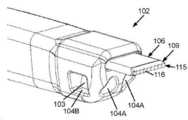
도 1은 본 발명의 실시예들에 따른 편도선 수술 흡인 절제 기구의 상측 투시도;
도 2는 편도선 수술 흡인 절제 기구의 하측 투시도;
도 3은 편도선 수술 흡인 절제 기구의 상측 평면도;
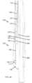
도 4는 편도선 수술 흡인 절제 기구의 측면 입면도;
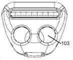
도 5는 편도선 수술 흡인 절제 기구의 전면 입면도;
도 6은 편도선 수술 흡인 절제 기구의 배면 입면도;
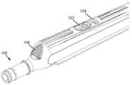
도 7은 편도선 수술 흡인 절제 기구의 흡인 끝단 단부의 상측 투시도;
도 8은 흡인 끝단의 단부의 하측 평면도;
도 9는 흡인 컵 단부의 전면 입면도;
도 10은 편도선 수술 흡인 절제 기구의 횡단면도;
도 11은 편도선 수술 흡인 절제 기구의 끝단 단부의 횡단면 측면도;
도 12는 편도선 수술 흡인 절제 기구의 핸들의 횡단면도;
도 13은 철회된 위치에 있는 절단 블레이드 부재의 후방을 향하는 위치를 예시한 도면;
도 14는 연장된 위치에 있는 절단 블레이드 부재의 전방을 향하는 위치를 예시한 도면.Now, preferred embodiments of the present invention will be described in more detail below with reference to the accompanying drawings provided as examples only:
1 is an upper perspective view of a tonsil surgical aspiration ablation apparatus according to embodiments of the present invention;
2 is a lower perspective view of a tonsil surgical aspiration ablation apparatus;
3 is a top plan view of the tonsil surgical aspiration ablation apparatus;
4 is a side elevational view of a tonsil surgical aspiration ablation apparatus;
5 is a front elevational view of a tonsil surgical aspiration ablation apparatus;
6 is a rear elevational view of the tonsil surgical aspiration ablation apparatus;
7 is an upper perspective view of the aspiration end end of the tonsil surgical aspiration ablation apparatus;
8 is a bottom plan view of the end of the suction end;
9 is a front elevational view of the end of the suction cup;
10 is a cross-sectional view of a tonsil surgical aspiration ablation apparatus;
11 is a cross-sectional side view of the distal end of a tonsil surgical aspiration ablation apparatus;
12 is a cross-sectional view of the handle of the tonsil surgical aspiration ablation apparatus;
13 illustrates a position facing the rear of the cutting blade member in the retracted position;
14 illustrates the forward facing position of the cutting blade member in the extended position.
편도선 수술 흡인 절제 기구(100)는 근위 핸들(101)과 원위 곡선형 끝단(102)을 포함한다. 기구(100)는 핸들(101)에 위치된 진공 튜브 연결부(105)와 끝단(102)의 단부에 위치된 하나 이상의 흡인 입구 포트(104)과 작동 가능하게 연결되는 하나 이상의 흡인 채널(103)을 포함한다.The tonsil surgical
도 1에 방향축이 제공되는데, 기구(100)는 가까운/근위 단부와 먼/원위 단부, 측면/횡방향 측면 및 상측/상부면 및 바닥/하부면을 포함하는 기다란 형태로 구성된다(elongate).An axial axis is provided in FIG. 1, wherein the
기구(100)는 끝단(102)을 따라 슬롯(107) 내에 슬라이딩 이동 가능하게 보유되는 가요성 절단 블레이드 부재(106)를 추가로 포함하되, 상기 가요성 절단 블레이드 부재(106)는, 핸들(101)에서 손으로 작동가능한 잠금 메커니즘(108)에 의해, 도 7, 8 및 11에 도시된 것과 같이, 절단 블레이드 부재(106)의 원위 절단 단부(109)가 끝단(102)의 단부로부터 돌출되는 연장된 위치와 원위 절단 단부(109)가 끝단(102)의 단부 내로 철회되는 철회된 위치 사이에서 작동될 수 있도록 구성된다.
기구(100)를 사용하는 방법은 흡인 기구를 진공 튜브 연결부(105)에 연결시키는 것을 포함한다. 곡선형 끝단(102)은 곡선형 끝단 단부가 목의 후방에 위치되도록 좌측면 또는 우측면으로부터 입 안으로 삽입된다. 잠금 메커니즘(108)은 절단 블레이드 부재(106)의 원위 절단 단부(109)를 끝단(102)의 단부로부터 연장하도록 구성될 수 있으며, 원위 절단 단부(109)는, 보통 반대쪽 손으로 한 쌍의 겸자로 끌어 당기면서, 각각의 편도선을 절제할 수 있다. 원위 절단 단부(109)는, 편도선을 겸자의 반대 방향으로 끌어당기면서 편도선 기저부(base)에 대해 전방을 향해 밀릴 수 있어서 편도선을 절제할 수 있는 수직의 일직선 절단 에지(115)를 형성한다.The method of using the
절제 시에, 유체가 흡인 입구 포트(104)들을 통해 배출될 수 있다. 어떤 시간에라도, 수술의사는 단독으로 흡인하기 위해 끝단(102)을 사용하여 원위 절단 단부(109)를 철회하도록 잠금 메커니즘(108)을 사용할 수 있으며, 필요 시에 원위 절단 단부(109)를 연장할 수 있다.Upon ablation, fluid may be drained through the
이러한 수술은 반대쪽 편도선을 위해 입의 반대쪽 횡방향 측면으로부터 곡선형 끝단(02)을 삽입함으로써 반복될 수 있다.This operation can be repeated by inserting the curved end 02 from the opposite transverse side of the mouth for the opposite tonsil.
한 바람직한 실시예에서, 핸들(101)과 끝단(102)은 플라스틱으로 일체형으로 형성된다. 또한, 절단 블레이드 부재(106)도 플라스틱으로 형성된다. 하지만, 절단 블레이드 부재(106)는 전기 소작 용도(electrocautery application)를 위해 전기 전도성을 지닐 수 있도록 금속으로 가요성있게 형성될 수도 있다(flexibly formed). 이에 따라, 흡인, 절제 및 전기 소작의 3가지 기능을 수행할 수 있게 되며, 출혈 지점을 즉각적으로 봉할 수 있다(seal). 또한, 기구에 전기 응고(electric coagulation)를 사용하면, 흉터가 난 편도선을 절제하기 위한 힘을 사용할 필요가 줄어들 것인데, 그 이유는 전기가 흉터 조직을 용해시키고, 응고시키면서, 최소 절제 힘을 사용하여, 보다 정확하게 절제하고, 조직 외상이 작고, 그에 따라 수술 후에 회복이 신속하고 통증이 덜 하기 때문이다.In one preferred embodiment, handle 101 and end 102 are integrally formed of plastic. Further, the
도 4를 살펴보면, 핸들(101)은 일반적으로 기다란 형태로 구성될 수 있으며, 그에 따라 기다란 축(elongate axis)을 가지고, 끝단(102)은 핸들의 원위 단부에서 약 40°만큼 벗어나도록(deviate) 핸들(101)의 기다란 축과 실질적으로 일직선으로부터 곡선 형태로 구성될 수 있다. 이 40° 곡률(curvature)로 인해, 수술의사의 손이 수술야(operating field) 외부에 위치되어, 일정한 가시성을 보장하고, 그와 동시에 40°의 매끄러운 곡률로 인해, 흡인 포트 내부에 적절한 흡인력(suction power)이 유지되며 흡인 포트 내부에 혈액 응고를 방지한다.Referring to FIG. 4, the
도 1 및 2를 보면, 진공 연결 포트(105)는 핸들(102)의 근위 단부로부터 연장될 수 있다. 도시된 실시예에서, 진공 연결 포트(105)는 일반적으로 원통 형태로 구성되며 핸들(101)의 기다란 축과 실질적으로 일직선인 기다란 축을 포함한다. 진공 연결 포트(105)는 O-링 밀봉부(113)와 연결 연동 고리(112)를 포함할 수 있다.1 and 2, the
도 7은 끝단(102)의 단부를 예시한 도면으로서, 연장된 위치에 있는 절단 블레이드 부재(106)를 보다 상세하게 보여준다.7 is a view illustrating the end of the
도시된 한 바람직한 실시예에서, 절단 블레이드 부재(109)는 평평한 단면을 가지며, 연장된 위치와 철회된 위치 사이에서 변환될 때 슬롯(107) 내에서 구부러질 수 있도록 길이방향 슬롯(107) 내에서 폭 방향으로 배열된다. 한 실시예에서, 절단 블레이드 부재(109)는 약 2mm의 두께와 약 10 밀리미터의 폭을 포함할 수 있다.In one preferred embodiment shown, the
한 바람직한 실시예에서, 절단 블레이드 부재(106)는 플라스틱으로 제작된다.In one preferred embodiment, the
도 7에 예시된 것과 같이, 원위 절단 단부(109)는 수직의 일직선 절단 에지(115)으로 좁아질 수 있다(narrow).As illustrated in FIG. 7, the
게다가, 절단 에지(115)는 상측으로부터 바닥으로 절단 에지(115)를 가로질러 수직으로 배열된 복수의 톱니(134)들을 포함할 수 있으며, 이러한 톱니(134)는, 절제 동안 절단 블레이드 부재(106)가 측면으로 미끄러지는 것을 방지하고 주변 조직이 손상되는 것을 피하기 위하여, 편도선 조직과 결합될 수 있다.In addition, the
도 11에 가장 잘 예시된 것과 같이, 절단 에지(115)는 한 지점으로 뾰족하게 형성되지 않고, 조작 동안, 의도치 않게 주변 조직을 손상시킬 수 있는 절단 작용의 효율을 제한하며, 필요 시에 편도선을 효율적으로 절단할 수 있도록 충분히 좁아질 수 있다. 예를 들어, 절단 에지(115)의 폭은 약 1mm일 수 있다. 또한, 블레이드 크기는 잘 절제할 수 있도록 충분히 크지만 주변 조직들이 부차적으로 손상되는 것을 항상 방지하기 위해 주변 조직들을 볼 수 있도록 가시성을 유지하기에는 충분히 작게끔 최적화된다.As best illustrated in FIG. 11, the
도 8을 보면, 연장된 위치에서 약 5 mm만큼 끝단(102)의 단부를 지나 연장되는 원위 절단 단부(109)가 도시된다.8, a
절단 블레이드 부재(106)에 대해 하측에 위치된 흡인 입구 포트(104)들이 예시된다.
게다가, 한 바람직한 실시예에서, 흡인 입구 포트(104)들은 끝단(102)의 단부의 다수의 면들에, 가령, 원위 위치에, 횡방향으로, 그리고 하측에 위치될 수 있어서, 폐색(occlusion)의 가능성이 줄어든다. 특히, 도 7은 한 쌍의 원위 입구 포트(104A), 맞은편에 위치된 한 쌍의 횡방향 흡인 입구 포트(104B)를 포함하는 흡인 입구 포트들을 도시하며, 도 8은 하부 입구 포트(104C)를 도시한다.In addition, in one preferred embodiment, the
도 12는 잠금 메커니즘을 보다 상세하게 보여주는 기구(100)의 횡단면도이다. 도시된 것과 같이, 절단 블레이드 부재(106)는 핸들(102)의 후방 구멍(117)으로부터 연장되는 근위 단부(116)를 포함할 수 있다. 근위 단부(116)의 근위 면(proximal face)은 전방에 위치될 때 핸들(102)의 근위 표면(117)과 수평으로 배열되도록 경사진다(angled).12 is a cross-sectional view of the
절단 블레이드 부재(106)는 리빙 힌지(121)에 의해 인접 부분(120)에 피벗회전 가능하게 결합된 잠금 레버(119)를 추가로 포함한다. 게다가, 핸들(102)의 상측면(122)은 주 후방 구멍(123)과 부 전방 구멍(124)을 포함하는데, 그 사이에서 레버(119)의 화살촉 형태의 보스(125)가 선택적으로 변환될 수 있다. 레버(119)는 레버(119)를 누르기 위하여 주 구멍(123)에 의해 접근가능한 후방 손잡이(126)를 포함한다. 게다가, 레버(119)는, 절단 블레이드 부재(106)가 연장된 위치에 있을 때, 맞은편 벽에 대해 접하는(abut) 지지대(127)와 원위 위치에서 끝을 이룬다(terminate distally).The
도 12는 철회된 형상(retracted configuration)에 있는 절단 블레이드 부재(106)를 도시한다. 절제를 위해 절단 블레이드 부재(109)를 연장하기 위하여, 검지손가락들로 핸들(102)의 밑부분(underneath)을 쥔 상태로, 후방 단부(116)는 보통 엄지손가락을 이용하여 핸들(102)의 기다란 축을 따라 전방으로 밀려질 수 있다. 화살촉 형태의 보스(125)의 전방 램프(129)가 레버(119)를 눌러서, 화살촉 형태의 보스(125)가 전방의 부 구멍(124) 내에 위치되는 시간 까지, 화살촉 형태의 보스(125)가 중간 부분(130) 밑에서 주 및 부 구멍(123, 124) 사이에서 변환할 수 있다. 상기 위치에 오면, 화살촉 형태의 보스(125)의 후방 수직 에지(135)는 중간 부분(130)의 전방 에지(131)에 대해 지지되어(jamb), 절단 블레이드 부재(106)가 압력 하에서 후방으로 슬라이딩 이동되는 것이 방지된다. 연장된 위치에서, 지지대(127)는 맞은편 벽(128)에 대해 접하여, 후방 단부(116)가 전방으로 이동되는 것이 제한될 수 있다.12 shows the
따라서, 절단 블레이드 부재(106)를 철회하기 위하여, 엄지손가락이 주 구멍(123) 내에 삽입되어 레버(119)를 누르고 이와 동시에 손잡이(126)의 전방 에지(132)에 대해 후방으로 끌어당기며, 손잡이(126)는 엄지손가락의 동작 하에서 절단 블레이드 부재(106)가 후방으로 슬라이딩 이동될 수 있으며 중간 부분(130)의 전방 에지(131)로부터 화살촉 형태의 보스(125)의 후방면(130)과 결합이 해제된다(disengage).Thus, in order to withdraw the
도 12에서 볼 수 있듯이, 슬롯(107)의 후방 부분(133)은 절단 블레이드 부재(106)가 완전히 후방으로 빠질 수 있도록(entire rearward removal) 충분히 넓다.12, the
잠금 메커니즘(108)이 엄지손가락 동작을 위해 구성될 수 있지만, 핸들(102)은 반대쪽 검지손가락의 파지력(grip)을 향상시키도록 형태가 구성될 수 있다. 특히, 도 5를 보면, 패널(102)은 평면 측벽들과 수직 하부 에지(111)를 포함하며, 핸들(102)에 비-원형 횡단면을 제공하고, 수술의사의 손 안에서 핸들이 회전하여 미끄러지는(rotational slipping) 것이 줄어들거나 방지될 수 있다.While the
위에서 기술된 내용들 중 특정 도면부호들로 제공한 것은 본 발명을 보다 잘 이해하기 위해서이다. 하지만, 통상의 기술자에게는, 본 발명을 실시하기 위하여 이러한 세부내용들이 반드시 필요한 것은 아니라는 것을 이해할 것이다. 따라서, 본 발명의 특정 실시예들에 대해 위에서 기술된 내용들은 본 발명을 단지 예시하고 설명하기 위한 것이다. 따라서, 본 발명을 이러한 내용들에만 제한하기 위한 것이 아니며, 그에 따라 본 발명의 다양한 변형예 및 개선예들이 가능하다. 상기 실시예들은 본 발명 및 본 발명의 적용용도의 개념을 가장 잘 설명하기 위해 선택되고 기술되었으며, 통상의 기술자라면 본 발명의 범위를 벗어나지 않고도 다양한 변형예들이 가능하다는 것을 이해할 수 있을 것이다. 따라서, 하기 청구항들이 본 발명의 범위를 정의한다.It is to better understand the present invention that are provided with specific reference numerals among the contents described above. However, it will be understood by those skilled in the art that these details are not necessary to practice the present invention. Accordingly, the foregoing descriptions of specific embodiments of the invention are intended to illustrate and explain the invention only. Therefore, the present invention is not intended to be limited only to these contents, and various modifications and improvements of the present invention are possible accordingly. The above embodiments have been selected and described in order to best describe the concept of the present invention and its application, and those skilled in the art will understand that various modifications are possible without departing from the scope of the present invention. Accordingly, the following claims define the scope of the invention.
Claims (28)
Translated fromKorean근위 핸들 및 원위 곡선형 끝단;
상기 끝단 내에서 끝단을 따라 끝단의 단부에 위치된 하나 이상의 흡인 입구 포트를 핸들에서 진공 포트에 작동 가능하게 연결하는 흡인 채널; 및
상기 끝단을 따라 슬롯 내에 슬라이딩 이동 가능하게 보유되는 가요성 절단 블레이드 부재를 포함하되, 상기 가요성 절단 블레이드 부재는, 손으로 작동가능한 잠금 메커니즘에 의해, 가요성 절단 블레이드 부재의 원위 절단 단부가 끝단의 단부로부터 연장되는 연장된 위치와 가요성 절단 블레이드 부재의 원위 절단 단부가 끝단의 단부 내로 철회되는 철회된 위치 사이에서 작동될 수 있도록 구성되는 것을 특징으로 하는 편도선 수술 흡인 절제 기구.A tonsil surgical aspiration ablation apparatus, wherein the tonsil surgical aspiration ablation apparatus is:
Proximal handle and distal curved end;
A suction channel operably connecting one or more suction inlet ports located at the ends of the ends along the ends within the ends; And
And a flexible cutting blade member slidably held in the slot along the end, wherein the flexible cutting blade member has a distal cutting end of the flexible cutting blade member by a hand-operated locking mechanism. A tonsil surgical aspiration ablation apparatus configured to be operable between an extended position extending from the end and a retracted position where the distal cut end of the flexible cutting blade member is withdrawn into the end of the end.
상기 방법은, 한 손으로, 절단 블레이드 부재를 전방으로 연장시켜, 동시에 절제하고 흡인하며, 오직 흡인을 위해 절단 블레이드 부재를 철회하는 단계를 포함하는 것을 특징으로 하는 편도선 수술 방법.In the tonsil surgery method using the tonsil surgery aspiration resection device according to claim 1,
The method comprises, with one hand, extending the cutting blade member forward, simultaneously ablation and aspiration, and withdrawing the cutting blade member for suction only.
Applications Claiming Priority (3)
| Application Number | Priority Date | Filing Date | Title |
|---|---|---|---|
| AU2017902866AAU2017902866A0 (en) | 2017-07-22 | A tonsillectomy suction tip dissector | |
| AU2017902866 | 2017-07-22 | ||
| PCT/AU2018/050487WO2019018877A1 (en) | 2017-07-22 | 2018-05-22 | Tonsillectomy suction dissector apparatus |
Publications (1)
| Publication Number | Publication Date |
|---|---|
| KR20200037144Atrue KR20200037144A (en) | 2020-04-08 |
Family
ID=65039230
Family Applications (1)
| Application Number | Title | Priority Date | Filing Date |
|---|---|---|---|
| KR1020197038108ACeasedKR20200037144A (en) | 2017-07-22 | 2018-05-22 | Tonsil surgery aspiration ablation apparatus |
Country Status (10)
| Country | Link |
|---|---|
| US (1) | US11395670B2 (en) |
| EP (1) | EP3629950A4 (en) |
| JP (1) | JP7171080B2 (en) |
| KR (1) | KR20200037144A (en) |
| CN (1) | CN110891502A (en) |
| AU (1) | AU2018308713B2 (en) |
| CA (1) | CA3067252A1 (en) |
| DE (1) | DE112018003752T5 (en) |
| GB (1) | GB2578377B (en) |
| WO (1) | WO2019018877A1 (en) |
Families Citing this family (1)
| Publication number | Priority date | Publication date | Assignee | Title |
|---|---|---|---|---|
| USD978346S1 (en) | 2022-08-12 | 2023-02-14 | Br Surgical, Llc | Separated finger pad for a surgical suction instrument |
Family Cites Families (24)
| Publication number | Priority date | Publication date | Assignee | Title |
|---|---|---|---|---|
| US3407815A (en)* | 1965-08-13 | 1968-10-29 | Abelson Louis | Adenotome having a flat cutting surface |
| US4307720A (en)* | 1979-07-26 | 1981-12-29 | Weber Jr Jaroy | Electrocautery apparatus and method and means for cleaning the same |
| US4674500A (en)* | 1985-09-27 | 1987-06-23 | Minnesota Mining And Manufacturing Company | Sheathed knife instrument |
| US5318565A (en)* | 1992-11-12 | 1994-06-07 | Daniel B. Kuriloff | Suction cautery dissector |
| US5481804A (en)* | 1994-10-12 | 1996-01-09 | Platts; David | Retractable-bladed knife |
| US6293945B1 (en)* | 2000-03-06 | 2001-09-25 | Everest Medical Corporation | Electrosurgical instrument with suction capability |
| US7131975B2 (en) | 2002-09-16 | 2006-11-07 | Medtronic Xomed, Inc. | Apparatus and methods for straightening angled tissue cutting instruments |
| WO2009058682A2 (en)* | 2007-10-30 | 2009-05-07 | Wilson-Cook Medical Inc. | Polyp tome |
| CN201256995Y (en)* | 2008-10-08 | 2009-06-17 | 石瑛 | Tonsil operation stripping device |
| US8137345B2 (en)* | 2009-01-05 | 2012-03-20 | Peak Surgical, Inc. | Electrosurgical devices for tonsillectomy and adenoidectomy |
| US9247954B2 (en) | 2010-04-21 | 2016-02-02 | Ravi Nallakrishnan Revocable Trust | Safety knife with retractable and extendable blade and guard |
| CN201727556U (en) | 2010-08-02 | 2011-02-02 | 朱永康 | Improved medical detacher |
| US8377086B2 (en) | 2011-01-25 | 2013-02-19 | Gyrus Ent L.L.C. | Surgical cutting instrument with distal suction passage forming member |
| US8728090B2 (en)* | 2012-01-12 | 2014-05-20 | Mohamad Farhadi | Tonsillar suction dissector |
| WO2014089369A1 (en) | 2012-12-05 | 2014-06-12 | Penblade, Llc | Safety cutting device |
| US9375253B2 (en)* | 2013-03-14 | 2016-06-28 | Megadyne Medical Products, Inc. | Electrosurgical instrument |
| WO2015048545A1 (en)* | 2013-09-27 | 2015-04-02 | Release Medical, Inc. | Tissue incision device |
| US20150335376A1 (en)* | 2014-05-21 | 2015-11-26 | Covidien Lp | Multipurpose electrosurgical instrument with telescoping aspiration cannula |
| JP6385742B2 (en) | 2014-07-09 | 2018-09-05 | 株式会社貝印刃物開発センター | Hand tools |
| WO2016044072A1 (en)* | 2014-09-18 | 2016-03-24 | Mayo Foundation For Medical Education And Research | Soft tissue cutting device and methods of use |
| CA3029355A1 (en)* | 2015-05-22 | 2016-11-22 | Covidien Lp | Surgical instruments and methods for performing tonsillectomy, adenoidectomy, and other surgical procedures |
| US10939899B2 (en)* | 2015-06-03 | 2021-03-09 | Obp Medical Corporation | End cap assembly for retractor and other medical devices |
| US20190021749A1 (en)* | 2017-07-19 | 2019-01-24 | Hoya Corporation | Universal retrieval device for removing obstructions from body lumens |
| US20190099209A1 (en)* | 2017-09-29 | 2019-04-04 | Ethicon Llc | Bipolar electrode saline linked closed loop modulated vacuum system |
- 2018
- 2018-05-22KRKR1020197038108Apatent/KR20200037144A/ennot_activeCeased
- 2018-05-22CACA3067252Apatent/CA3067252A1/enactivePending
- 2018-05-22JPJP2020524655Apatent/JP7171080B2/enactiveActive
- 2018-05-22CNCN201880044729.5Apatent/CN110891502A/enactivePending
- 2018-05-22DEDE112018003752.5Tpatent/DE112018003752T5/ennot_activeWithdrawn
- 2018-05-22EPEP18838057.0Apatent/EP3629950A4/ennot_activeWithdrawn
- 2018-05-22WOPCT/AU2018/050487patent/WO2019018877A1/ennot_activeCeased
- 2018-05-22GBGB1918119.7Apatent/GB2578377B/ennot_activeExpired - Fee Related
- 2018-05-22USUS16/632,854patent/US11395670B2/enactiveActive
- 2018-05-22AUAU2018308713Apatent/AU2018308713B2/ennot_activeCeased
Also Published As
| Publication number | Publication date |
|---|---|
| GB2578377A (en) | 2020-05-06 |
| CA3067252A1 (en) | 2019-01-31 |
| JP2020528332A (en) | 2020-09-24 |
| GB201918119D0 (en) | 2020-01-22 |
| AU2018308713B2 (en) | 2020-01-23 |
| EP3629950A1 (en) | 2020-04-08 |
| US11395670B2 (en) | 2022-07-26 |
| US20210307770A1 (en) | 2021-10-07 |
| EP3629950A4 (en) | 2021-03-03 |
| WO2019018877A1 (en) | 2019-01-31 |
| GB2578377B (en) | 2022-08-03 |
| AU2018308713A1 (en) | 2020-01-16 |
| CN110891502A (en) | 2020-03-17 |
| JP7171080B2 (en) | 2022-11-15 |
| DE112018003752T5 (en) | 2020-04-16 |
Similar Documents
| Publication | Publication Date | Title |
|---|---|---|
| US7147637B2 (en) | Surgical instrument | |
| US20090209827A1 (en) | Suction Retraction Surgical Instrument | |
| US5569298A (en) | Resposable scissors | |
| JP5149904B2 (en) | Cylindrical shaft equipment | |
| US9649128B2 (en) | Adjustable curette | |
| US20130261600A1 (en) | Surgical instrument with distal suction capability | |
| WO2004098382A3 (en) | Suction coagulator with dissecting probe | |
| JP2004510469A (en) | Endoscopic cutting machine | |
| KR102616319B1 (en) | Locking mechanism for extendable shafts | |
| US10149695B2 (en) | Microsurgical instruments | |
| KR20200037144A (en) | Tonsil surgery aspiration ablation apparatus | |
| KR102664539B1 (en) | Diathermic tonsil surgery suction ablation device | |
| HK40024516A (en) | Tonsillectomy suction dissector apparatus | |
| CN214632242U (en) | Disposable forceps knife for endoscope | |
| CN222398728U (en) | Laparoscope cold knife with operation area flushing and negative pressure suction device | |
| CN210872002U (en) | Endoscopic minimally invasive surgical instrument | |
| US20240108401A1 (en) | Multi-function ergonomic handheld surgical instrument and system | |
| CN115835826A (en) | Multifunctional surgical instrument | |
| CN118058804A (en) | Cutting tool for soft tissue separation | |
| CN117462235A (en) | Dedicated curer of three-purpose laparoscopic surgery electrotome of inhaling of cutting of mammary gland operation | |
| CN110384541A (en) | One kind being exclusively used in single-blade stndon sheath incision knife |
Legal Events
| Date | Code | Title | Description |
|---|---|---|---|
| PA0105 | International application | Patent event date:20191224 Patent event code:PA01051R01D Comment text:International Patent Application | |
| PG1501 | Laying open of application | ||
| PA0201 | Request for examination | Patent event code:PA02012R01D Patent event date:20210521 Comment text:Request for Examination of Application | |
| E902 | Notification of reason for refusal | ||
| PE0902 | Notice of grounds for rejection | Comment text:Notification of reason for refusal Patent event date:20230404 Patent event code:PE09021S01D | |
| E601 | Decision to refuse application | ||
| PE0601 | Decision on rejection of patent | Patent event date:20230607 Comment text:Decision to Refuse Application Patent event code:PE06012S01D Patent event date:20230404 Comment text:Notification of reason for refusal Patent event code:PE06011S01I |