KR20200035362A - Hf-surgical preparation instrument with fluid channel - Google Patents
Hf-surgical preparation instrument with fluid channelDownload PDFInfo
- Publication number
- KR20200035362A KR20200035362AKR1020190117957AKR20190117957AKR20200035362AKR 20200035362 AKR20200035362 AKR 20200035362AKR 1020190117957 AKR1020190117957 AKR 1020190117957AKR 20190117957 AKR20190117957 AKR 20190117957AKR 20200035362 AKR20200035362 AKR 20200035362A
- Authority
- KR
- South Korea
- Prior art keywords
- electrode
- channel
- instrument
- insulating body
- section
- Prior art date
- Legal status (The legal status is an assumption and is not a legal conclusion. Google has not performed a legal analysis and makes no representation as to the accuracy of the status listed.)
- Granted
Links
Images


Classifications
- A—HUMAN NECESSITIES
- A61—MEDICAL OR VETERINARY SCIENCE; HYGIENE
- A61B—DIAGNOSIS; SURGERY; IDENTIFICATION
- A61B18/00—Surgical instruments, devices or methods for transferring non-mechanical forms of energy to or from the body
- A61B18/04—Surgical instruments, devices or methods for transferring non-mechanical forms of energy to or from the body by heating
- A61B18/12—Surgical instruments, devices or methods for transferring non-mechanical forms of energy to or from the body by heating by passing a current through the tissue to be heated, e.g. high-frequency current
- A61B18/14—Probes or electrodes therefor
- A61B18/1442—Probes having pivoting end effectors, e.g. forceps
- A—HUMAN NECESSITIES
- A61—MEDICAL OR VETERINARY SCIENCE; HYGIENE
- A61B—DIAGNOSIS; SURGERY; IDENTIFICATION
- A61B18/00—Surgical instruments, devices or methods for transferring non-mechanical forms of energy to or from the body
- A61B18/04—Surgical instruments, devices or methods for transferring non-mechanical forms of energy to or from the body by heating
- A61B18/12—Surgical instruments, devices or methods for transferring non-mechanical forms of energy to or from the body by heating by passing a current through the tissue to be heated, e.g. high-frequency current
- A61B18/14—Probes or electrodes therefor
- A61B18/1402—Probes for open surgery
- A—HUMAN NECESSITIES
- A61—MEDICAL OR VETERINARY SCIENCE; HYGIENE
- A61B—DIAGNOSIS; SURGERY; IDENTIFICATION
- A61B18/00—Surgical instruments, devices or methods for transferring non-mechanical forms of energy to or from the body
- A61B18/04—Surgical instruments, devices or methods for transferring non-mechanical forms of energy to or from the body by heating
- A61B18/12—Surgical instruments, devices or methods for transferring non-mechanical forms of energy to or from the body by heating by passing a current through the tissue to be heated, e.g. high-frequency current
- A—HUMAN NECESSITIES
- A61—MEDICAL OR VETERINARY SCIENCE; HYGIENE
- A61B—DIAGNOSIS; SURGERY; IDENTIFICATION
- A61B17/00—Surgical instruments, devices or methods
- A61B17/32—Surgical cutting instruments
- A61B17/3203—Fluid jet cutting instruments
- A—HUMAN NECESSITIES
- A61—MEDICAL OR VETERINARY SCIENCE; HYGIENE
- A61B—DIAGNOSIS; SURGERY; IDENTIFICATION
- A61B18/00—Surgical instruments, devices or methods for transferring non-mechanical forms of energy to or from the body
- A61B18/04—Surgical instruments, devices or methods for transferring non-mechanical forms of energy to or from the body by heating
- A61B18/12—Surgical instruments, devices or methods for transferring non-mechanical forms of energy to or from the body by heating by passing a current through the tissue to be heated, e.g. high-frequency current
- A61B18/1206—Generators therefor
- A61B18/1233—Generators therefor with circuits for assuring patient safety
- A—HUMAN NECESSITIES
- A61—MEDICAL OR VETERINARY SCIENCE; HYGIENE
- A61B—DIAGNOSIS; SURGERY; IDENTIFICATION
- A61B18/00—Surgical instruments, devices or methods for transferring non-mechanical forms of energy to or from the body
- A61B18/04—Surgical instruments, devices or methods for transferring non-mechanical forms of energy to or from the body by heating
- A61B18/12—Surgical instruments, devices or methods for transferring non-mechanical forms of energy to or from the body by heating by passing a current through the tissue to be heated, e.g. high-frequency current
- A61B18/14—Probes or electrodes therefor
- A61B18/1482—Probes or electrodes therefor having a long rigid shaft for accessing the inner body transcutaneously in minimal invasive surgery, e.g. laparoscopy
- A—HUMAN NECESSITIES
- A61—MEDICAL OR VETERINARY SCIENCE; HYGIENE
- A61B—DIAGNOSIS; SURGERY; IDENTIFICATION
- A61B17/00—Surgical instruments, devices or methods
- A61B17/32—Surgical cutting instruments
- A61B17/3203—Fluid jet cutting instruments
- A61B2017/32035—Fluid jet cutting instruments with gas or air
- A—HUMAN NECESSITIES
- A61—MEDICAL OR VETERINARY SCIENCE; HYGIENE
- A61B—DIAGNOSIS; SURGERY; IDENTIFICATION
- A61B18/00—Surgical instruments, devices or methods for transferring non-mechanical forms of energy to or from the body
- A61B2018/00005—Cooling or heating of the probe or tissue immediately surrounding the probe
- A61B2018/00011—Cooling or heating of the probe or tissue immediately surrounding the probe with fluids
- A61B2018/00023—Cooling or heating of the probe or tissue immediately surrounding the probe with fluids closed, i.e. without wound contact by the fluid
- A—HUMAN NECESSITIES
- A61—MEDICAL OR VETERINARY SCIENCE; HYGIENE
- A61B—DIAGNOSIS; SURGERY; IDENTIFICATION
- A61B18/00—Surgical instruments, devices or methods for transferring non-mechanical forms of energy to or from the body
- A61B2018/00005—Cooling or heating of the probe or tissue immediately surrounding the probe
- A61B2018/00011—Cooling or heating of the probe or tissue immediately surrounding the probe with fluids
- A61B2018/00029—Cooling or heating of the probe or tissue immediately surrounding the probe with fluids open
- A—HUMAN NECESSITIES
- A61—MEDICAL OR VETERINARY SCIENCE; HYGIENE
- A61B—DIAGNOSIS; SURGERY; IDENTIFICATION
- A61B18/00—Surgical instruments, devices or methods for transferring non-mechanical forms of energy to or from the body
- A61B2018/00053—Mechanical features of the instrument of device
- A61B2018/00059—Material properties
- A61B2018/00071—Electrical conductivity
- A61B2018/00083—Electrical conductivity low, i.e. electrically insulating
- A—HUMAN NECESSITIES
- A61—MEDICAL OR VETERINARY SCIENCE; HYGIENE
- A61B—DIAGNOSIS; SURGERY; IDENTIFICATION
- A61B18/00—Surgical instruments, devices or methods for transferring non-mechanical forms of energy to or from the body
- A61B2018/00315—Surgical instruments, devices or methods for transferring non-mechanical forms of energy to or from the body for treatment of particular body parts
- A61B2018/00345—Vascular system
- A—HUMAN NECESSITIES
- A61—MEDICAL OR VETERINARY SCIENCE; HYGIENE
- A61B—DIAGNOSIS; SURGERY; IDENTIFICATION
- A61B18/00—Surgical instruments, devices or methods for transferring non-mechanical forms of energy to or from the body
- A61B2018/00315—Surgical instruments, devices or methods for transferring non-mechanical forms of energy to or from the body for treatment of particular body parts
- A61B2018/00434—Neural system
- A—HUMAN NECESSITIES
- A61—MEDICAL OR VETERINARY SCIENCE; HYGIENE
- A61B—DIAGNOSIS; SURGERY; IDENTIFICATION
- A61B18/00—Surgical instruments, devices or methods for transferring non-mechanical forms of energy to or from the body
- A61B2018/00571—Surgical instruments, devices or methods for transferring non-mechanical forms of energy to or from the body for achieving a particular surgical effect
- A61B2018/00601—Cutting
- A—HUMAN NECESSITIES
- A61—MEDICAL OR VETERINARY SCIENCE; HYGIENE
- A61B—DIAGNOSIS; SURGERY; IDENTIFICATION
- A61B18/00—Surgical instruments, devices or methods for transferring non-mechanical forms of energy to or from the body
- A61B2018/00964—Features of probes
- A61B2018/0097—Cleaning probe surfaces
- A—HUMAN NECESSITIES
- A61—MEDICAL OR VETERINARY SCIENCE; HYGIENE
- A61B—DIAGNOSIS; SURGERY; IDENTIFICATION
- A61B18/00—Surgical instruments, devices or methods for transferring non-mechanical forms of energy to or from the body
- A61B2018/00982—Surgical instruments, devices or methods for transferring non-mechanical forms of energy to or from the body combined with or comprising means for visual or photographic inspections inside the body, e.g. endoscopes
- A—HUMAN NECESSITIES
- A61—MEDICAL OR VETERINARY SCIENCE; HYGIENE
- A61B—DIAGNOSIS; SURGERY; IDENTIFICATION
- A61B18/00—Surgical instruments, devices or methods for transferring non-mechanical forms of energy to or from the body
- A61B18/04—Surgical instruments, devices or methods for transferring non-mechanical forms of energy to or from the body by heating
- A61B18/12—Surgical instruments, devices or methods for transferring non-mechanical forms of energy to or from the body by heating by passing a current through the tissue to be heated, e.g. high-frequency current
- A61B18/14—Probes or electrodes therefor
- A61B2018/1405—Electrodes having a specific shape
- A61B2018/1412—Blade
- A—HUMAN NECESSITIES
- A61—MEDICAL OR VETERINARY SCIENCE; HYGIENE
- A61B—DIAGNOSIS; SURGERY; IDENTIFICATION
- A61B18/00—Surgical instruments, devices or methods for transferring non-mechanical forms of energy to or from the body
- A61B18/04—Surgical instruments, devices or methods for transferring non-mechanical forms of energy to or from the body by heating
- A61B18/12—Surgical instruments, devices or methods for transferring non-mechanical forms of energy to or from the body by heating by passing a current through the tissue to be heated, e.g. high-frequency current
- A61B18/14—Probes or electrodes therefor
- A61B2018/1405—Electrodes having a specific shape
- A61B2018/1422—Hook
- A—HUMAN NECESSITIES
- A61—MEDICAL OR VETERINARY SCIENCE; HYGIENE
- A61B—DIAGNOSIS; SURGERY; IDENTIFICATION
- A61B18/00—Surgical instruments, devices or methods for transferring non-mechanical forms of energy to or from the body
- A61B18/04—Surgical instruments, devices or methods for transferring non-mechanical forms of energy to or from the body by heating
- A61B18/12—Surgical instruments, devices or methods for transferring non-mechanical forms of energy to or from the body by heating by passing a current through the tissue to be heated, e.g. high-frequency current
- A61B18/14—Probes or electrodes therefor
- A61B18/1442—Probes having pivoting end effectors, e.g. forceps
- A61B2018/1452—Probes having pivoting end effectors, e.g. forceps including means for cutting
- A—HUMAN NECESSITIES
- A61—MEDICAL OR VETERINARY SCIENCE; HYGIENE
- A61B—DIAGNOSIS; SURGERY; IDENTIFICATION
- A61B18/00—Surgical instruments, devices or methods for transferring non-mechanical forms of energy to or from the body
- A61B18/04—Surgical instruments, devices or methods for transferring non-mechanical forms of energy to or from the body by heating
- A61B18/12—Surgical instruments, devices or methods for transferring non-mechanical forms of energy to or from the body by heating by passing a current through the tissue to be heated, e.g. high-frequency current
- A61B18/14—Probes or electrodes therefor
- A61B2018/1465—Deformable electrodes
- A—HUMAN NECESSITIES
- A61—MEDICAL OR VETERINARY SCIENCE; HYGIENE
- A61B—DIAGNOSIS; SURGERY; IDENTIFICATION
- A61B2218/00—Details of surgical instruments, devices or methods for transferring non-mechanical forms of energy to or from the body
- A61B2218/001—Details of surgical instruments, devices or methods for transferring non-mechanical forms of energy to or from the body having means for irrigation and/or aspiration of substances to and/or from the surgical site
- A61B2218/002—Irrigation
- A61B2218/003—Irrigation using a spray or a foam
- A—HUMAN NECESSITIES
- A61—MEDICAL OR VETERINARY SCIENCE; HYGIENE
- A61B—DIAGNOSIS; SURGERY; IDENTIFICATION
- A61B2218/00—Details of surgical instruments, devices or methods for transferring non-mechanical forms of energy to or from the body
- A61B2218/001—Details of surgical instruments, devices or methods for transferring non-mechanical forms of energy to or from the body having means for irrigation and/or aspiration of substances to and/or from the surgical site
- A61B2218/002—Irrigation
- A61B2218/005—Irrigation using gas or vapor, e.g. for protection or purging
- A—HUMAN NECESSITIES
- A61—MEDICAL OR VETERINARY SCIENCE; HYGIENE
- A61B—DIAGNOSIS; SURGERY; IDENTIFICATION
- A61B2218/00—Details of surgical instruments, devices or methods for transferring non-mechanical forms of energy to or from the body
- A61B2218/001—Details of surgical instruments, devices or methods for transferring non-mechanical forms of energy to or from the body having means for irrigation and/or aspiration of substances to and/or from the surgical site
- A61B2218/002—Irrigation
- A61B2218/006—Irrigation for smoke evacuation
Landscapes
- Health & Medical Sciences (AREA)
- Surgery (AREA)
- Life Sciences & Earth Sciences (AREA)
- Engineering & Computer Science (AREA)
- Biomedical Technology (AREA)
- Public Health (AREA)
- Nuclear Medicine, Radiotherapy & Molecular Imaging (AREA)
- Veterinary Medicine (AREA)
- General Health & Medical Sciences (AREA)
- Heart & Thoracic Surgery (AREA)
- Medical Informatics (AREA)
- Molecular Biology (AREA)
- Animal Behavior & Ethology (AREA)
- Physics & Mathematics (AREA)
- Otolaryngology (AREA)
- Plasma & Fusion (AREA)
- Surgical Instruments (AREA)
- Electrostatic Spraying Apparatus (AREA)
Abstract
Description
Translated fromKorean본 발명은 HF-수술 준비 기구에 관한 것이다.The present invention relates to an HF-surgical preparation instrument.
집게 및 클램프를 갖는 엄격한 기계적 준비 이외에, 오늘날에는 동맥 경화 절차[고주파(HF) 수술 절차]가 선택의 수단이다. 현재, 비절연 스패튤라 또는 후크 전극이 조직 구조의 준비에 사용된다. 대조적으로, 부분적으로 절연된 전극은 특히 여분의 구조 또는 인접한 구조의 열적 손상이 가능한 최소일 때 사용된다. 알려진 준비 기구의 경우, 예를 들어, 흐르는 혈액, 탄화된 혈액 및 조직 뿐 아니라 "유동" 조직으로 인한 기구 팁(활성 영역) 위에 오버레이된 결과로 인해 수술 부위의 제한된 시야로 인해 정확하고 안전한 작업이 어려워질 수 있다.In addition to strict mechanical preparation with forceps and clamps, arteriosclerosis procedures (high frequency (HF) surgical procedures) are the means of choice today. Currently, non-insulated spatula or hook electrodes are used for the preparation of tissue structures. In contrast, partially insulated electrodes are used, especially when the thermal damage of the redundant or adjacent structures is as minimal as possible. For known preparation instruments, accurate and safe operation is possible due to the limited field of view of the surgical site, for example, as a result of overlaying on the instrument tip (active area) due to “flow” tissue as well as flowing blood, carbonized blood and tissue. It can be difficult.
공개공보 미국 2006/0 111 709 A1은 후크 전극을 포함하는 전기수술 기구를 개시하며, 냉각 유체는 저장소로부터 기구 몸체를 통해 전극 팁으로 전극의 개구를 통해 그리고 이로부터 복귀 채널 내로 들어가서 다시 저장소로 운반될 수 있다. 따라서, 전극을 냉각시킬 수 있다.Publication US 2006/0 111 709 A1 discloses an electrosurgical instrument comprising a hook electrode, wherein cooling fluid enters the electrode tip from the reservoir through the body of the electrode through the opening of the electrode and into the return channel and transports it back to the reservoir. Can be. Therefore, the electrode can be cooled.
공개공보 WO 95/19 739 A는 자유 단부를 갖는 전극을 갖는 전기수술 기구를 개시하며, 여기서 전극은 단부 전까지 전기 절연 물질의 코팅부에 의해 둘러싸이고, 여기서 - 단부에 인접하는 코팅부의 섹션에서 - 개구를 통해 조직에 HF-출력을 인가하기 위해 전극으로부터 코팅부의 표면까지 연장되는 코팅부에 상기 개구가 포함된다.Publication WO 95/19 739 A discloses an electrosurgical instrument having an electrode with a free end, wherein the electrode is enclosed by a coating of electrically insulating material until the end, where-in a section of the coating adjacent to the end- The opening is included in the coating extending from the electrode to the surface of the coating to apply HF-power to the tissue through the opening.
공개공보 WO 2016/0731 64 A1은 전극의 단부로부터 산소를 변위시키기 위해 전극의 단부의 개구로부터 가스가 배출되는 채널을 둘러싸는 비절연 전극을 갖는 전기수술 기구를 도시한다.Publication WO 2016/0731 64 A1 shows an electrosurgical instrument having a non-insulated electrode surrounding a channel through which gas is discharged from an opening at the end of the electrode to displace oxygen from the end of the electrode.
웹 사이트http://mmcts.org/tutorial/830#additionalinfo는 전기수술 기구 및 CO2와 식염수의 혼합물을 분배하기 위한 기구를 결합하는 기구를 개시하며, 여기서 전기수술 기구 및 추가 기구는 나사에 의해 연결된다.The websitehttp://mmcts.org/tutorial/830#additionalinfo discloses an electrosurgical instrument and a mechanism for combining the instrument for dispensing a mixture of CO2 and saline, wherein the electrosurgical instrument and additional instrument are screw Connected.
이 종래 기술을 고려하면, 본 발명의 목적은 개선된 기구를 제공하는 것이다.In view of this prior art, the object of the present invention is to provide an improved mechanism.
이 목적은 청구항 1에 따른 HF-수술 준비 기구 및 청구항 15에 따른 장치에 의해 달성된다 :This object is achieved by the HF-surgical preparation instrument according to claim 1 and the device according to claim 15:
HF-수술 준비 기구(이하, 준비 기구 또는 기구라고도 함)는 조직에 HF-출력을 인가하기 위한 전극을 포함하며, 여기서 전극의 표면 섹션은 절연 몸체에 의해서 외부 방향으로 전기적으로 및 열적으로 절연된다. 채널은 절연 몸체 내부에 제공되며, 상기 채널은 가스, 유체 및/또는 에어로졸과 같은 유체를 조직 상에 또는 조직 내로 또는 조직 구조들 사이에 분배하도록 구성된다. 채널은 유체 소스, 예를 들어, 가스 소스, 유체 소스 및/또는 에어로졸 소스일 수 있거나 이들에 연결될 수 있다.The HF-surgical preparation device (hereinafter also referred to as a preparation device or device) includes an electrode for applying HF-output to the tissue, wherein the surface section of the electrode is electrically and thermally insulated outward by an insulating body. . A channel is provided inside the insulating body, and the channel is configured to distribute a fluid, such as gas, fluid, and / or aerosol, onto or into the tissue or between tissue structures. The channel can be a fluid source, for example a gas source, a fluid source and / or an aerosol source, or can be connected to them.
바람직하게는, 상기 기구는 단극성 HF 기구이다. 기구에 제공되는 HF-발전기는 환자의 넓은 영역과 전기적으로 접촉하는 별도의 중성 전극에 연결된다.Preferably, the instrument is a unipolar HF instrument. The HF-generator provided to the instrument is connected to a separate neutral electrode in electrical contact with a large area of the patient.
HF-수술 준비 기구에 의해, 가스, 유체 및/또는 에어로졸이 HF-출력의 작용 영역 내에 또는 옆에 분배될 수 있다. 따라서, 준비 기구는 유체 도포기를 형성한다.By means of an HF-surgical preparation instrument, gas, fluid and / or aerosol can be dispensed within or next to the working area of the HF-output. Thus, the preparation mechanism forms a fluid applicator.
본 특허 출원의 의미 내에서, 에어로졸은 가스와 액체의 혼합물, 특히 가스에 현탁된 액체 방울인 것으로 이해되어야 한다.Within the meaning of this patent application, it should be understood that an aerosol is a mixture of a gas and a liquid, especially a liquid droplet suspended in a gas.
본 발명의 기구를 사용하여 부드럽고 정밀한 방식으로 조직을 준비할 수 있다. 여기서, 준비는 무딘 분리/변위 및/또는 예리한 분리에 의한, 예를 들어, 신경 또는 혈관과 같은 취약한 해부학적 구조의 노출 및 제시를 의미하는 것으로 이해된다. HF-수술 준비에서, 예를 들어, HF-스패튤라(HF-spatula)는 혈관, 신경 및 기관과 같은 특정 조직 구조를 조직 복합체로부터 적어도 부분적으로 분리시키기 위해 사용된다. 이 단계 동안, 민감한(준비될) 또는 인접한 구조에 대한 의도하지 않은 열적 손상이 없어야 한다. 본 발명에 따른 기구는 조직과 HF 전극 사이의 접촉 표면이 알려지거나 언제든지 제어될 수 있음을 보장한다. 본 발명의 기구의 가스, 유체 및/또는 에어로졸 도포기 기능에 의해 조직, 조직 구조, 조직 잔류물, 체액 또는 다른 유체 또는 증기를 이동시키거나 이동 또는 변위시킴으로써, 외과의는 항상 개별 조직 경계를 명확하게 인식할 수 있다.The apparatus of the present invention can be used to prepare tissue in a smooth and precise manner. Here, preparation is understood to mean exposure and presentation of fragile anatomical structures such as, for example, nerves or blood vessels, by blunt separation / displacement and / or sharp separation. In HF-surgical preparation, for example, HF-spatula is used to at least partially separate certain tissue structures, such as blood vessels, nerves, and organs, from tissue complexes. During this stage, there should be no unintentional thermal damage to sensitive (to be prepared) or adjacent structures. The instrument according to the invention ensures that the contact surface between the tissue and the HF electrode can be known or controlled at any time. By moving, moving, or displacing tissue, tissue structures, tissue residues, body fluids, or other fluids or vapors by the gas, fluid, and / or aerosol applicator functions of the instrument of the present invention, the surgeon always clearly defines the individual tissue boundaries. Can be recognized.
바람직하게는, 채널은 거리를 두고 또는 거리없이 전극 옆으로 연장된다. 대안적으로, 전극은 채널을 포함할 수 있다. 그러나, 절연 몸체는 채널을 한정하는 것이 바람직하다. 이것은 절연 몸체가 적어도 부분적으로 채널 벽을 형성한다는 것을 의미한다. 예를 들어, 이 섹션에서 절연 몸체에서 작은 튜브를 생략할 수 있으며, 작은 튜브는 채널 섹션을 포함한다. 바람직하게는, 채널은 절연 몸체의 벽 두께 내에서 연장된다. 바람직하게는, 전극은 채널을 따라 채널로부터 거리를 두고 연장된다. 바람직하게는, 전극은 채널 내에 배열되지 않고, 바람직하게는 채널 내로 연장되지 않아 채널이 채널을 통한 단면에서 볼 때 전극을 둘러싸지 않는다.Preferably, the channel extends laterally or without distance. Alternatively, the electrode can include a channel. However, it is preferred that the insulating body defines a channel. This means that the insulating body at least partially forms a channel wall. For example, a small tube can be omitted from the insulating body in this section, and the small tube includes a channel section. Preferably, the channel extends within the wall thickness of the insulating body. Preferably, the electrodes extend along the channel at a distance from the channel. Preferably, the electrodes are not arranged in the channel, and preferably do not extend into the channel so that the channel does not surround the electrode when viewed in cross section through the channel.
바람직하게는, 채널은 단면, 특히 채널의 직경이 테이퍼지는 단부 섹션에 노즐 섹션을 갖는다. 바람직하게는, 노즐 섹션은 절연 몸체에 의해 한정된다. 이는 절연 몸체가 채널의 노즐 섹션의 벽을 형성한다는 것을 의미한다.Preferably, the channel has a nozzle section in cross section, in particular an end section where the diameter of the channel is tapered. Preferably, the nozzle section is defined by an insulating body. This means that the insulating body forms the wall of the nozzle section of the channel.
원위 단부 섹션(기구 팁), 특히 전극 및 절연 몸체는 바람직하게는 절연 몸체 및 전극의 형태를 처리 작업에 맞추기 위해 가요성이다. 굽힘에 사용되는 외력이 제거되면, 절연 몸체의 단부 섹션의 원하는 형태가 유지되는 것이 바람직하다. 전극 팁에 대한 채널의 노즐의 배향은 유지되는 것이 바람직하다. 바람직하게는, 단부 섹션은 수동으로 구부러질 수 있다. 단부 섹션이 원하는 형태로 구부러질 수 있는 경우, 이는 예를 들어, 혈관을 제거하는 동안과 같이 정밀하고 조직 보호적인 준비를 촉진시킨다.The distal end section (mechanical tip), in particular the electrode and insulating body, is preferably flexible to tailor the shape of the insulating body and electrode to the processing operation. When the external force used for bending is removed, it is desirable that the desired shape of the end section of the insulating body is maintained. Preferably, the orientation of the nozzle of the channel relative to the electrode tip is maintained. Preferably, the end section can be bent manually. If the end section can be bent to the desired shape, this promotes precise and tissue protective preparation, for example, while removing blood vessels.
절연으로 인해, 전극과 조직 사이의 전기 접촉 영역은 한정되고 좁은 제한 영역으로 설정될 수 있다. 그 결과, 조직으로 유입되는 에너지는 한편으로 감소한다. 반면, 유효 범위가 제한되어 있기 때문에, 주변 조직에 대한 측면 손상뿐만 아니라 부주의한 열 응력의 위험이 최소화된다.Due to the insulation, the electrical contact area between the electrode and the tissue can be set to a limited and narrow limiting area. As a result, energy entering the tissue is reduced on the one hand. On the other hand, since the effective range is limited, the risk of inadvertent thermal stress as well as lateral damage to surrounding tissue is minimized.
절연 몸체가 채널을 한정하는 경우, 특히 절연 몸체가 채널의 개구에서 에어로졸 또는 유체의 기구의 유효 영역으로의 분배를 허용하는 채널의 단부 섹션을 한정하는 경우, 이는 기구가 구부러진 경우, 채널의 단부 섹션의 배향(각도)이 전극의 원위 단부 섹션의 배향에 대해 유지되는 결과를 갖는다.If the insulating body defines a channel, especially if the insulating body defines an end section of the channel that allows the distribution of the aerosol or fluid from the opening of the channel to the effective area of the device, this means that if the device is bent, the end section of the channel Has the result that the orientation (angle) of is maintained with respect to the orientation of the distal end section of the electrode.
바람직하게는, 전극은 유체 스트림을 운반하기에 적합한 채널에 배치되지 않는다. 전극은 절연 몸체의 리세스에 배치될 수 있다. 전극은 리세스를 완전히 채우거나 리세스 내의 개구를 적어도 닫을 수 있다.Preferably, the electrode is not placed in a channel suitable for carrying a fluid stream. The electrode can be disposed in the recess of the insulating body. The electrode can completely fill the recess or at least close the opening in the recess.
바람직한 실시예에서, 전극은 주걱 형상을 갖는다. 이는 전극이 적어도 하나의 주걱형 원위 단부 섹션을 포함한다는 것을 의미한다. HF-스패튤라와 함께, 기구는 주걱형 전극을 형성한다. 바람직한 실시예에서, 전극은 바람직하게는 전극의 길이방향 범위를 따라 연장되는 와이어형 섹션을 갖는다. 대안적으로, 전극은 예를 들어, 전극의 근위 단부로부터 전극의 단부 섹션까지 연장될 수 있는 세장형 슬릿 또는 리세스를 가질 수 있으며, 여기서 와이어형 몸체, 바람직하게는 금속 몸체는 슬릿 또는 리세스에 배치된다. 바람직하게는, 와이어형 몸체는 전극에 연결되고, 바람직하게는 전극 판금에 용접된다. 와이어형 몸체는 반드시 전류를 전도하도록 구성될 필요는 없지만, 기구의 단부 섹션을 구부리고 단부 섹션을 원하는 구부러진 형태로 유지하기 위해 엄격하게 기계적인 목적으로 배열될 수도 있다. 따라서, 와이어형 몸체는 전극 내로 전력을 출력하고 및/또는 전극을 기계적으로 안정화시키도록 구성될 수 있다. 특히 정밀하고 절연된 방식으로 준비 기구를 제조할 수 있게 하기 위해, 얇은 전극이 바람직하다. 그러나, 전극의 두께가 감소함에 따라, 전극의 기계적 강성이 감소한다. 필요한 경우, 이는 와이어형 몸체 또는 섹션에 의해 보상될 수 있다. 더욱이, 와이어형 몸체 또는 섹션은 준비 기구의 팁으로부터 준비 기구의 단부 섹션을 통해 열 에너지의 제거를 향상시킬 수 있다.In a preferred embodiment, the electrode has a spatula shape. This means that the electrode comprises at least one spatula distal end section. Together with the HF-spatula, the instrument forms a spatula-like electrode. In a preferred embodiment, the electrode preferably has a wire-shaped section extending along the longitudinal range of the electrode. Alternatively, the electrode can have an elongated slit or recess that can extend from the proximal end of the electrode to the end section of the electrode, for example, where the wire-like body, preferably the metal body, is a slit or recess. Is placed on. Preferably, the wire-like body is connected to the electrode, preferably welded to the electrode sheet metal. The wire-like body is not necessarily configured to conduct current, but can also be arranged for strictly mechanical purposes to bend the end section of the instrument and keep the end section in the desired bent shape. Thus, the wire-like body can be configured to output power into the electrode and / or mechanically stabilize the electrode. In order to be able to manufacture the preparation device in a particularly precise and insulated manner, thin electrodes are preferred. However, as the thickness of the electrode decreases, the mechanical stiffness of the electrode decreases. If necessary, this can be compensated by a wire-like body or section. Moreover, the wired body or section can improve the removal of thermal energy from the tip of the preparation instrument through the end section of the preparation instrument.
본 발명에 따른 기구의 예시적인 실시예에서와 같이, HF-스패튤라가 유체 도포기(하이브리드 스패튤라)와 조합되면, 이에 의해 구조의 열 손상이 크게 감소될 수 있으며, 수술 부위의 투시를 개선할 수 있다. 기구는 조직을 변위시키거나 조직을 상승시키기 위해 조직에 유체, 예를 들어, 가스, 유체 또는 이 둘의 혼합물의 도포 또는 도입을 허용한다. 그 결과, 개별 조직 구조 또는 경계가 보다 명확하게 표시될 수 있다. 또한, 유체를 분배함으로써, 특히 혈액, 조직 잔류물, 증기, 연기 등과 같은 체액을 헹구거나 변위시킬 수 있다.As in the exemplary embodiment of the instrument according to the present invention, if the HF-spatula is combined with a fluid applicator (hybrid spatula), thereby significantly reducing the thermal damage of the structure and improving the perspective of the surgical site. can do. The instrument allows application or introduction of a fluid, eg, gas, fluid or a mixture of the two, into the tissue to displace or elevate the tissue. As a result, individual tissue structures or boundaries can be more clearly displayed. In addition, by dispensing fluids, it is possible to rinse or displace body fluids, particularly blood, tissue residues, vapors, smoke, and the like.
높은 전력 밀도에 의해 유체(특히 액체)를 도포하는 동안, 상기 유체는 조직을 관통하여 표적 구조과 인접한 구조 사이의 결합 조직 유사 경계 영역에 축적되어 이들이 눌려지도록 하고 그리고 기구를 조작하기 위한 확대된(안전) 거리가 형성된다(기계적 및 열적 보호).During the application of fluids (especially liquids) by high power density, the fluid penetrates the tissue and accumulates in the connective tissue-like boundary region between the target structure and adjacent structures, allowing them to be pressed and expanded (safety) for manipulating the instrument. ) Distance is formed (mechanical and thermal protection).
이와 반대로, 유체 스트림(특히, 가스)이 비교적 낮은 강도로 조직의 특정 거리로부터 지향되는 경우, 스트리밍 유체의 힘의 작용으로 인해 조직에 변위 효과(변형)가 발생한다. 상이한 기계적 특성, 예를 들어, 개별 조직 구조의 탄성으로 인해, 이러한 효과는 다소 현저할 수 있다. 결과적으로, 예를 들어, 지방과 같은 주위의 연질 조직에 대해 혈관과 같은 딱딱한 구조를 보다 명확하게 제한할 수 있다.Conversely, when a fluid stream (especially a gas) is directed from a specific distance of tissue at a relatively low intensity, a displacement effect (strain) occurs in the tissue due to the action of the force of the streaming fluid. Due to different mechanical properties, for example the elasticity of individual tissue structures, this effect can be rather pronounced. As a result, it is possible to more clearly limit rigid structures such as blood vessels to surrounding soft tissue, for example fat.
또한, 에어로졸 스프레이를 도포함으로써, 수술 부위의 냉각을 구현할 수 있으며, 따라서, HF 노출로 인한 열적 손상에 대한 추가 보호를 구현할 수 있다. 에어로졸이 HF 인가 동안 연기 형성을 감소시키는 한, 수술 부위의 시야가 명확하게 개선될 수 있다.In addition, by applying an aerosol spray, cooling of the surgical site can be achieved, and thus additional protection against thermal damage due to HF exposure can be implemented. As long as the aerosol reduces smoke formation during HF application, the field of view of the surgical site can be clearly improved.
유체, 특히 에어로졸의 유해한 영향을 피하고 및/또는 특히 가스, 에어로졸이 조직, 예를 들어, 혈관, 채널의 출구로의 도입을 방지하는데 도움을 주기 위해 구체적으로, 노즐의 출구는 바람직하게는 전극의 원위 단부로부터 근위 방향으로 세트 백될 수 있다. 결과적으로, 특히 조직의 채널 출구의 배치가 방지된다. 바람직한 실시예에서, 출구가 제공되는 채널의 원위 단부는 2mm 내지 10mm 만큼 전극의 원위 단부로부터 세트 백된다. 실시예들에서, 채널의 원위 단부 또는 채널의 출구는 전극의 원위 단부로부터, 예를 들어, 2 내지 4 mm 사이에서 근위 방향으로 세트 백될 수 있다.Specifically, the outlet of the nozzle is preferably of the electrode, in order to avoid the harmful effects of fluids, in particular aerosols and / or in particular to help prevent the introduction of gas, aerosols into the outlets of tissues, eg blood vessels, channels. It can be set back in the proximal direction from the distal end. As a result, the arrangement of the channel outlets of the tissues in particular is prevented. In a preferred embodiment, the distal end of the channel provided with the outlet is set back from the distal end of the electrode by 2 mm to 10 mm. In embodiments, the distal end of the channel or the outlet of the channel may be set back in the proximal direction from the distal end of the electrode, for example between 2 and 4 mm.
주걱형 전극은 하나의 측면을 통해 전극의 에지에 각각 연결된 상부면 및 하부면을 갖는다. 채널의 원위 단부 섹션은 바람직하게는 전극의 길이방향 축 또는 와이어형 섹션 또는 몸체의 길이방향 축 또는 채널의 출구 하류에 있는 채널의 출구로부터 유체의 유동 방향으로 배열되는 전극 또는 절연 몸체의 길이방향 섹션에 의해 그리고 전극의 상부면 또는 하부면의 표면 법선에 의해 각각 걸쳐지는 평면에 위치된다. 채널의 원위 단부 섹션과 전극 및/또는 와이어형 몸체의 길이방향 범위 및/또는 채널의 출구의 하류에 있는 채널의 출구로부터 유동 방향으로 배열되는 전극 또는 절연 몸체의 섹션의 길이방향 축 사이의 배향 각도(방위각)는 특히 바람직하게는 0 °이다. 대안적으로, 방위각은 0 °± 10 ° 또는 0 °± 5 °일 수 있거나 다른 각도 범위를 포함할 수 있다. 방위각은 바람직하게는 주걱형 전극이 위치되거나 또는 이 평면에 위치되는 방식으로 구부러질 수 있고 및/또는 절연 몸체 또는 전극의 섹션이 위치되는 평면에서 측정되고, 상기 섹션은 채널의 출구와 절연 몸체 및/또는 전극의 원위 단부 사이에 배치된다.The spatula-shaped electrode has an upper surface and a lower surface, respectively connected to the edges of the electrodes through one side. The distal end section of the channel is preferably a longitudinal section of the electrode or insulating body arranged in the flow direction of the fluid from the longitudinal axis of the electrode or the wired section or the longitudinal axis of the body or the outlet of the channel downstream of the outlet of the channel. And by the surface normals of the top or bottom surface of the electrode, respectively. Orientation angle between the distal end section of the channel and the longitudinal axis of the section of the electrode or insulating body arranged in the flow direction from the outlet of the channel downstream of the outlet of the channel and / or the longitudinal extent of the electrode and / or wired body (Azimuth angle) is particularly preferably 0 °. Alternatively, the azimuth angle can be 0 ° ± 10 ° or 0 ° ± 5 ° or can include other angular ranges. The azimuth angle is preferably measured in the plane in which the spatula-like electrode is located or bent in such a way that it is located in this plane, and / or is measured in the plane in which the section of the insulating body or electrode is located, the section of the channel and the insulating body And / or between the distal ends of the electrodes.
기구의 실시예에서, 전극은 가스, 유체 및/또는 에어로졸이 운반되는 개구를 갖지 않는다. 특히, 전극은 바람직하게는 전극이 연장되는 채널을 갖지 않으며, 이 채널은 작동 중에 가스, 에어로졸 또는 유체를 운반할 것이다. In embodiments of the instrument, the electrode does not have an opening through which gas, fluid, and / or aerosols are carried. In particular, the electrode preferably does not have a channel through which the electrode extends, which channel will carry gas, aerosol or fluid during operation.
본 발명에 따른 기구의 전극은 바람직하게는 절연 몸체로부터 원위로 돌출한다. 이러한 방식으로, 조직 내로의 HF-출력의 전달은 또한 비절연 섹션을 통해 전극으로부터 측방향으로 시작된다.The electrode of the appliance according to the invention preferably projects distally from the insulating body. In this way, the transfer of HF-output into the tissue also starts laterally from the electrode through the non-isolated section.
바람직하게는, 절연 몸체에 의해 커버되지 않는 전극의 상부면 및/또는 하부면의 영역은 바람직하게는 아치형이거나 또는 (평면에서) 아치형 방식으로 절연 몸체를 둘러싼다. 비커버 영역은 채널의 출구와 기구의 원위 단부 사이에 배치된 절연 몸체의 섹션 옆에서 끝날 수 있다. 따라서, 비커버 영역은 - 사용자의 관점에서 - 출구의 원위에서 끝난다. 대안적으로, 비커버 영역은 채널을 포함하는 절연 몸체의 섹션 옆에서 끝날 수 있다. 따라서, 비커버 영역은 출구의 근위에서 끝난다. 비커버 영역이 채널의 출구의 근위에서 끝나면, 전극의 노출된 영역은 채널의 출구를 넘어서 출구 옆의 근위 방향으로 연장된다.Preferably, the areas of the upper and / or lower surfaces of the electrode not covered by the insulating body are preferably arcuate or surround the insulating body in an arcuate (in planar) manner. The uncovered area may end next to a section of the insulating body disposed between the outlet of the channel and the distal end of the instrument. Thus, the non-covered area ends at the distal end of the exit-from the user's point of view. Alternatively, the non-covered area can end next to a section of the insulating body that includes the channel. Thus, the uncovered area ends at the proximal end of the exit. When the uncovered region ends proximate the exit of the channel, the exposed region of the electrode extends beyond the exit of the channel in the proximal direction next to the exit.
절연 몸체에 의한 비적용 영역은 다음 에지 표면 섹션이 원위 방향으로 성분과 배향을 갖는 전극의 영역으로 제한될 수 있다. 절연 몸체에 의한 비적용 영역은 특히 최인접 에지 표면 섹션이 전극의 전면 섹션인 전극의 영역으로 제한될 수 있다.The unapplied area by the insulating body can be limited to the area of the electrode where the next edge surface section has a component and orientation in the distal direction. The non-applicable area by the insulating body may be limited to the area of the electrode, in particular where the nearest edge surface section is the front section of the electrode.
절연 몸체는 하나의 부분 또는 다수의 부분으로 구성될 수 있다. 절연 몸체의 부분들은 서로 연결될 수 있거나 또는 부분들은 분리되어 이격되어 있다. 바람직하게는, 절연 몸체는 이음매없는 단일 조각으로 구성된다. 전극은 절연 몸체의 리세스에 배치될 수 있거나, 또는 전극은 예를 들어, 절연 몸체의 2 개의 연결되지 않은 반쪽들 사이에 배열될 수 있으며, 상기 반쪽은 전극의 상부면 및 하부면의 섹션들을 2차원으로 커버할 수 있다.The insulating body may be composed of one part or multiple parts. The parts of the insulating body can be connected to each other or the parts are separated and spaced apart. Preferably, the insulating body consists of a single seamless piece. The electrode can be disposed in the recess of the insulated body, or the electrode can be arranged, for example, between two unconnected halves of the insulated body, the halves of the upper and lower sections of the electrode. It can be covered in two dimensions.
바람직하게는, 절연 몸체는 중합체, 특히 플라스틱 물질, 예를 들어, 실리콘으로 구성된다. 바람직하게는, 절연 몸체는 기구의 원위 단부 섹션이 구부러질 수 있도록 가요성이다. 절연 몸체는 커버된 표면 섹션의 조직이 외과적으로 효과적이거나 손상되는 전기 출력으로 충전되는 것을 방지하기 위해 전극의 표면 섹션을 커버한다. 예를 들어, 이러한 방식으로 조직 섹션의 바람직하지 않은 건조가 방지될 수 있다. 절연 몸체에 의해 커버되지 않은 표면 섹션으로부터, 외과적으로 효과적인 방식으로 조직에 전기적 출력을 인가하는 것이 가능하다.Preferably, the insulating body is composed of a polymer, in particular a plastic material, for example silicone. Preferably, the insulating body is flexible so that the distal end section of the instrument can be bent. The insulating body covers the surface section of the electrode to prevent the tissue of the covered surface section from filling with surgically effective or damaging electrical output. For example, undesirable drying of the tissue section can be prevented in this way. From the surface section not covered by the insulating body, it is possible to apply electrical output to the tissue in a surgically effective manner.
바람직한 실시예에서, 절연 몸체는 전극을 오버몰딩하여 제조된다. 바람직하게는, 코어는 본 발명에 따른 기구의 제조 동안 전극 옆 및/또는 전극 샤프트 옆의 외부 형태로 바람직하게는 전극 및/또는 전극 샤프트를 따라 거리를 두고 배치되며, 상기 코어는 전극이 오버몰딩되는 동안 채널의 적어도 섹션을 형성하거나 또는 채널의 적어도 섹션을 자유 상태로 남겨 둔다. 전극을 둘러싸는 절연 몸체의 벽 두께 내에 채널이 잔류한다.In a preferred embodiment, the insulating body is made by overmolding the electrodes. Preferably, the core is arranged in an external form next to the electrode and / or next to the electrode shaft during manufacture of the instrument according to the invention, preferably at a distance along the electrode and / or electrode shaft, wherein the core is overmolded with an electrode. While forming at least a section of the channel or leaving at least a section of the channel free. Channels remain within the wall thickness of the insulating body surrounding the electrode.
바람직하게는, 전극은 절연 몸체를 전극에 고정시키기 위한 리세스, 특히 구멍을 갖는다. 절연 몸체가 주조, 특히 사출 성형에 의해 제조되는 경우, 주조 재료는 구멍을 관통하고 구멍 내에서 응고되어, 절연 몸체와 전극 사이에 포지티브 로킹이 생성될 수 있다.Preferably, the electrode has a recess, in particular a hole, for fixing the insulating body to the electrode. When the insulating body is produced by casting, especially injection molding, the casting material penetrates the hole and solidifies within the hole, so that positive locking between the insulating body and the electrode can be created.
바람직하게는, 전극은 전극 샤프트에 유지되며, 절연 몸체는 상기 샤프트를 전기 절연시키기 위해 전극 샤프트의 적어도 하나의 원위 단부 섹션을 둘러쌀 수 있다. 와이어형 몸체는 전극 샤프트 내에 또는 전극 샤프트 상에 고정될 수 있으며, 특히 전극 샤프트에 삽입될 수 있다.Preferably, the electrode is held on the electrode shaft, and the insulating body can surround at least one distal end section of the electrode shaft to electrically insulate the shaft. The wire-like body can be fixed in the electrode shaft or on the electrode shaft, and in particular can be inserted into the electrode shaft.
채널은 전극 샤프트 옆에 또는 예를 들어, 전극 샤프트와 동심으로 섹션에서 연장된다.The channel extends in the section next to the electrode shaft or concentrically with the electrode shaft, for example.
기구는 전극 샤프트가 회전 가능하도록 지지되는 핸들을 가질 수 있고, 사용자는 핸들에 대한 전극의 각도 위치를 조정할 수 있다. 채널이 전극 샤프트에 대해 동심으로 연장되면, 채널은 가스, 유체 및/또는 에어로졸 라인을 통해 가스, 유체 및/또는 에어로졸 소스에 중심 집중식으로 연결될 수 있다.The instrument can have a handle to which the electrode shaft is rotatable, and the user can adjust the angular position of the electrode relative to the handle. If the channel extends concentrically with respect to the electrode shaft, the channel can be centrally connected to the gas, fluid and / or aerosol source via gas, fluid and / or aerosol lines.
또한, 본 발명에 따른 기구 및 가스, 유체 및/또는 에어로졸 소스를 포함하는 장치가 개시되며, 기구의 채널은 채널에 가스, 액체 및/또는 에어로졸을 공급하기 위하여 가스, 유체 및/또는 에어로졸 소스에 연결된다.In addition, an apparatus and a device comprising a gas, fluid and / or aerosol source according to the present invention are disclosed, wherein the channel of the apparatus is provided with a gas, fluid and / or aerosol source to supply gas, liquid and / or aerosol to the channel. Connected.
본 발명에 따른 기구 및 본 발명에 따른 장치의 추가적인 바람직한 특징 및 실시예는 도면뿐만 아니라 상세한 설명 및 종속항으로부터 추론될 수 있다. 그들은 보여
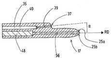
도 1은 본 발명에 따른 기구의 예시적인 실시예의 사시도.
도 2는 도 1에 따른 기구의 원위 단부의 평면도.
도 3은 전극의 위치 및 채널이 점선으로 표시된 도 1에 따른 기구의 사시도.
도 4는 도 1에 따른 기구의 전극 샤프트 및 전극을 갖는 예시적인 전극 조립체를 도시한 도면.
도 5는 전극의 길이방향 축을 따라 도 1에 따른 기구의 길이방향 단면의 세부사항을 도시한 도면.
도 6a 및 도 6b는 원위 스패튤라 섹션의 예시적인 실시예의 평면도.
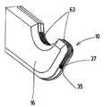
도 7a는 본 발명에 따른 기구의 추가 실시예의 예의 원위 단부 섹션의 사시도.
도 7b는 도 7a에 따른 예의 길이방향 단면도.
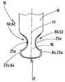
도 8a는 본 발명에 따른 기구의 제 3 실시예의 예의 사시도.
도 8b는 본 발명에 따른 기구의 제 3 실시예에 따른 추가 예의 상부면의 평면도.
도 8c는 본 발명의 기구의 제 3 실시예에 따른 또 다른 예의 사시도.Additional preferred features and embodiments of the device according to the invention and the device according to the invention can be deduced from the detailed description and dependent claims as well as the drawings. They show
1 is a perspective view of an exemplary embodiment of an instrument according to the invention.
FIG. 2 is a plan view of the distal end of the instrument according to FIG. 1;
Fig. 3 is a perspective view of the instrument according to Fig. 1 with the electrode positions and channels shown in dotted lines.
4 shows an exemplary electrode assembly with an electrode shaft and electrodes of the instrument according to FIG. 1.
5 shows details of the longitudinal cross-section of the instrument according to FIG. 1 along the longitudinal axis of the electrode.
6A and 6B are top views of exemplary embodiments of distal spatula sections.
7A is a perspective view of a distal end section of an example of a further embodiment of the instrument according to the invention.
7b is a longitudinal sectional view of the example according to FIG. 7a;
8A is a perspective view of an example of a third embodiment of an instrument according to the invention.
8B is a plan view of the upper surface of a further example according to a third embodiment of the instrument according to the invention.
8C is a perspective view of another example according to a third embodiment of the instrument of the present invention.
도 1 내지 도 5는 본 발명에 따른 일 실시예에서 본 발명에 따른 준비 기구(10)의 바람직한 구조의 예의 상세사항을 도시한다. 준비 기구(10)는 전극(13) 및 전극 샤프트(14)를 구비한 전극 조립체(12)(특히, 도 3 및 도 4 참조)를 포함하고, 전극(13)은 전극 샤프트(14)에 유지된다. 전극 샤프트(14)의 근위 단부는 기구(10)의 핸들(미도시)에 해제가능하게 삽입될 수 있다. 전극 조립체(12)는 전극 샤프트의 길이방향 축을 중심으로 전극 조립체(12)의 회전 방향을 조절할 수 있도록 핸들 내에 회전 가능하게 지지될 수 있다. 전극 샤프트(14)를 통해, 전극(13)은 HF-발전기(미도시)에 전기적으로 연결된다. 전극(13)은 전극(13)을 부분적으로 절연하는 절연 몸체(16)에 의해 둘러싸여 있다. 이는 절연 몸체(16)가 조직이 절연 섹션의 표면을 통해 가로질러 외과적으로 효과적인, 특히 절단 - 또는 손상되는 전기 출력으로 충전되는 것을 방지하기 위해 전극(13)의 절연 섹션을 커버하는 것을 의미한다. 절연 몸체(16)는 상기 전극을 절연시키기 위해 전극(13)의 표면 섹션을 커버하거나 바람직하게는 2 차원 방식으로 전극(13)의 표면 섹션에 적응된다. 절연 몸체(16)는 바람직하게는 전극 샤프트(14)의 적어도 단부를 둘러싸고 그로부터 기구(10)의 작업 팁(17)까지 연장되며, 여기서 절연 몸체(16)는 노출된 전극(13)의 에지 영역(20)을 남긴다. 준비 기구(10)는 전극 샤프트(14)로부터 준비 기구(10)의 원위 단부까지 연장되는 단부 섹션(21)을 갖는다.1 to 5 show details of an example of a preferred structure of the
전극(13)은 상부면(22a)과 하부면(22b)이 반대 방향에서 마주하는 주걱 형태를 갖는다. 상부면(22a) 및 하부면(22b)은 각각의 측부 상의 하나의 측면(23a, 23b)을 통해 그리고 측면(23a, 23b)에 인접한 전면(24)에 원위로 서로 측방향으로 연결된다. 측면(23a, 23b) 및 전면(24)은 전극(13)의 에지 표면을 형성한다.The
바람직하게는, 전면(24)은 완전히 또는 적어도 부분적으로 절연되지 않는다. 측면(23a, 23b)은 바람직하게는 전면(24)까지 절연된다. 바람직하게는, 전극(13)은 절연 몸체(16)로부터 원위로 돌출한다. 바람직하게는, 전극(13)은 전면(24)에 인접한 절연 몸체(16)로부터 돌출한다.Preferably, the
측면(23a, 23b) 및/또는 전면(24)에서, 전극(13)은 측면(23a, 23b) 또는 전면(24)을 향해 개방된 리세스가 없는 것이 바람직하며, 상기 리세스는 잠재적으로 예를 들어, 전극(13)의 후크 형상을 형성한다.In the
특히 바람직하게는, 전면(24)에 인접한 상부면(22a)의 아치형(곡선 스트립 형태) 섹션(25a) 및/또는 하부면(22b)의 그러한 섹션(25b)은 절연되지 않으며, 섹션 또는 섹션들(25a)은 - 상부면(22a) 및/또는 하부면(22b)의 평면도에서 - 절연 몸체(16)를 둘러싼다. 스트립형 섹션 또는 섹션들(25a, 25b)은 전면(24)에 인접한다. 스트립형 섹션 또는 섹션들(25a, 25b)은 예를 들어, 0.05 mm 내지 2 mm의 폭(B)을 가질 수 있다. 도 6a 및 도 6b에 따른 예시적인 실시예에서, 스트립형 섹션은 예를 들어, 0.1mm 내지 0.15mm의 폭(B)을 갖는다.Particularly preferably, the arcuate (curved strip-shaped)
바람직하게는, 전극(13)은 그 근위 단부(28)로부터 자유 스트립형 섹션(25a, 25b)까지 절연 몸체에 의해 연속적으로 둘러싸여 있다. 전면(24)의 섹션은 그에 둘러싸여 있는 전극(13)의 표면 섹션(29)에 인접하고, 상기 섹션은 둘러싸인 표면 섹션(29)까지 전극(13)의 원위 단부(38) 주위에서 연속적으로 커버되지 않는다.Preferably, the
준비 기구(10)의 단부 섹션(21)의 폭은 바람직하게는 절연 몸체(16)의 폭(32)에 의해 한정된다. 바람직하게는, 전극(13)은 절연 몸체(16)로 끝나거나 또는 절연 몸체(16)보다 작은 폭(33)을 갖는다. .The width of the
절연 몸체 내부에서, 전극(13)을 둘러싸는 벽에서, 전극(13)을 따라 채널(35)이 연장된다. 채널(35)과 전극(13)은 바람직하게는 채널(35)과 전극(13) 사이의 공간(도시된 바와 같이)으로 또는 공간없이 서로 옆으로 연장된다. 단부 섹션(21)의 원위 단부(36)에서, 채널(35)은 출구(37)를 갖는다. 예를 들어, 전극(13)과 평행하게 측정된 출구(37)는 예를 들어, 2 mm 내지 4 mm 사이에서, 적어도 2 mm 에서 10 mm까지 세트백될 수 있다.Inside the insulating body, in the wall surrounding the
채널(35)은 절연 몸체(16)에서 도시된 실시예에 따라 절연 몸체(16)의 상부면(22a)에 인접하거나, 예를 들어, 절연 몸체(16)의 하부면(22b)(미도시)에 인접하여 배치된다. 채널 또는 채널의 하나의 브랜치가 또한 상부면(22a)에 인접하고 하부면(22b)(미도시)에 인접하여 각각 배치될 수 있다. 채널은 다른 측면, 하부 면(22b) 또는 상부면(22a)에 인접하여 배치될 수 있다. 채널(35)은(도 3에 도시된 바와 같이) 평행 방향으로 또는 초기에 전극(13)을 따라[전극(13)에 평행한 직선 전극(13)으로] - 적어도 전극 샤프트(14)에 대해 동심인 섹션으로(미도시) 연장되고, 바람직하게는, 채널(35)의 직선 단부 섹션(39)은 전극(13)에 대해 각이져서, 채널(35)의 단부 섹션(39)의 길이방향 축과 전극(13)의 길이방향 축(41)에 의해 둘러싸인 각도(α)가 원위 방향(RD)으로 개방된다. 각도(α)는 기구(10)의 원위 단부 섹션을 통한 길이방향 단면도를 도시하는 도 5에 도시된다. 대응하는 단면 평면은도 2에서 파선으로 표시된 교차 선을 따라 수직으로 도 2의 종이 평면(paper plane)과 교차한다. 채널(35)의 원위 단부 섹션(39)은 바람직하게는 전극(13)의 섹션의 길이방향 축(41)에 대해 또는 출구(37)의 하류에 있는 출구(38)로부터 유체의 유동 방향으로 배치된 절연 몸체(16)에 대해 바람직하게는 0 ° 초과 내지 45 °이하, 특히 바람직하게는 5 °초과 내지 25 ° 미만, 예를 들어, 15 ± 3 °의 각도(α)로 각도진다. 채널(35)에 액체 또는 에어로졸이 공급되면, 액체 또는 에어로졸은 예를 들어, 원추 형태, 예를 들어, 완전한 원추 형태인 채널의 상기 출구(37) 밖으로 흐른다. 예를 들어, 원추는 대략 20 °의 개구 각도(원추 각도)를 가질 수 있다. 채널(35)의 원위 단부 섹션(39)의 배향으로 인해, 원추는 이 원추가 채널(36)의 출구(37)와 전극(13)의 원위 단부(38) 또는 기구(10) 사이의 전극(13) 또는 절연 몸체(16)와 접촉하지 않는 방식으로 배향될 수 있다. 예시적인 실시예에서, 유체 원추는 분무 원추 "표면"이 기구(10)의 섹션(44)의 표면에 대략 평행하거나 접선이 되도록 배향될 수 있고, 상기 섹션은 채널(35)의 출구(37)로부터 기구(10)의 원위 단부까지 연장된다. 그러나, 분사 원추가 섹션(44)에 충돌하는 경우, 이는 상당히 제어되지 않은 방울 형성(전극 팁의 액체 축적)을 초래할 수 있고 기구 팁의 전도성 액체의 축적으로 인해 전극의 유효 접촉 표면이 확대될 수 있기 때문에, 한편으로는 스패튤라의 전기적 특성에 부정적인 영향을 줄 수 있으므로 축적은 정확한(절연된) 준비의 목적과 상충될 수 있고, 다른 한편으로는 작동 영역의 시야를 제한할 수 있다.The
도 3에 도시된 바와 같이, 특히 도 5에 도시된 바와 같이, 채널(35)의 원위 단부 섹션(39)은 바람직하게는 평면을 따라 평행하게 배향되거나, 또는 전극(13)의 상부면(22a) 또는 하부면(22b)에 수직인 평면에 위치되고 상기 평면은 전극(13), 출구(37)의 하류에 있는 출구(37)로부터 유체의 유동 방향으로 배열되는 와이어형 섹션 또는 절연 몸체의 길이방향 연장 방향으로 연장된다. 채널(35)의 원위 단부 섹션(39)과 전극(13) 및/또는 와이어형 섹션 또는 몸체(48)의 길이방향 연장 방향 및/또는 출구(37) 하류의 출구(37)에서 유체의 유동 방향으로 배열되는 전극(13) 또는 절연 몸체(16) 섹션의 길이방향 축 사이의 방위각은 바람직하게는 0 °이며, 여기서 방위각은 평면 상의 채널(35)의 원위 단부 섹션(39)의 길이방향 축의 수직 투영 사이에서 측정되고, 주걱형 전극(13)은 이 평면 및/또는 절연 몸체(16) 또는 전극(13)의 섹션이 위치하는 평면에 위치되는 방식으로 위치되거나 구부러질 수 있고 상기 섹션은 채널(35)의 출구(37)와 절연 몸체(16) 및/또는 전극(13)의 원위 단부와 전극(13) 및/또는 와이어형 몸체(48) 또는 섹션의 길이방향 연장 방향 및/또는 출구(37)로부터 유체의 유동 방향으로 볼 때 하류에 배치된 전극(13) 또는 절연 몸체(16)의 섹션의 길이방향 축 사이에 배치된다.As shown in FIG. 3, particularly as shown in FIG. 5, the
채널(35)의 원위 단부 섹션(39)은 바람직하게는 원위 단부 섹션(39)에 근위로 인접한 채널 섹션(40)의 유동 단면보다 작은 유동 단면을 갖는 노즐 섹션이다. 근위로 인접한 채널 섹션(40)은 바람직하게는 1mm 이하, 예를 들어, 약 0.6mm의 직경을 갖는다.The
절연 몸체(16) 및 전극(13)을 갖는 기구(10)의 원위 단부 섹션(21)은 바람직하게는 가요성이며, 맨손으로 구부릴 수 있고 - 구부러진 후 - 바람직하게는 사용자가 원하는 형상으로 유지된다. 결과적으로 기구(10)의 단부 섹션(21)은 기구(10)의 단부 섹션(21)의 형상을 수술 작업에 적응시키는 방향으로 특히 전극(13) 및 절연 몸체(16)의 직선 배향으로부터 구부러질 수 있다.The
기구(10)의 단부 섹션(21)을 수동으로 구부림으로써 특히 정밀하게 배향시키기 위해, 채널(35)은 바람직하게는 절연 몸체(16) 내에 개방된 중공 공간에 의해 형성된다. 도시된 바와 같이, 중공 공간은 바람직하게는 절연 몸체(16) 내의 공간으로부터 거리를 두고 옆으로 연장되고, 상기 공간은 전극(13)으로 채워진다. 따라서, 절연 몸체(16)는 채널(35)을 한정하는 벽을 형성하는 것이 바람직하다. 채널(35)을 한정하는 벽들은 바람직하게는 절연 몸체(16)와 일체로 이음매없도록 구성된다. 대안적으로 또는 부가적으로, 채널의 원위 단부 섹션(39), 특히 노즐 섹션은 바람직하게는 절연 몸체(16) 내에 개방된 상태로 남겨진 중공 공간에 의해 형성된다.For particularly precise orientation by manually bending the
바람직하게는, 기구(10)는 노즐 섹션(39)의 배향이 원위 전극 섹션(38) 및/또는 절연 몸체(16)의 섹션 및/또는 채널(35)을 통한 유체의 유동 방향으로 볼 때, 출구(37)의 하류[출구(37)의 원위]에 배치된 전극의 섹션의 길이방향 축(41)에 대해서 구부러질 때, 유지되도록 구성된다. 이는 기구(10)의 원위 단부 섹션(21)의 영역에 노즐 섹션(39)을 구성함으로써 보장되며, 상기 섹션은 원위 단부 섹션(21)을 구부리기 위해 사용자에 의해 유지되고, 결과적으로 구부림 모멘트가 발생하지 않는다. 결과적으로, 기구(10)의 원위 단부 섹션(21)의 구부러짐은 항상 노즐 섹션(39) 근위에 발생한다. 특히, 출구(37) 및/또는 노즐 섹션(39)과 전극의 원위 단부(38) 사이의 거리는 단부 섹션(21)을 구부리는 동안, 기구(10)의 원위 단부 섹션(21)의 구부러짐이 항상 노즐 섹션(39)에 근위에 보장될 수 있도록 충분히 작게 선택될 수 있다.Preferably, the
전극(13)과 함께, 바람직하게는 금속의 와이어형 몸체(48)가 배치된다. 전극(13)은 예를 들어, 전극(13)의 근위 단부(28)로부터 전극(13)의 원위 단부(38)까지 전극의 길이방향 연장 방향으로 연장될 수 있는 길이방향 슬릿 또는 컷아웃을 가질 수 있고, 이 경우에 와이어형 몸체(48)는 슬릿 또는 컷아웃에 배치되고 도시된 바와 같이 컷아웃을 채울 수 있다. 대안적으로, 전극(13)은 예를 들어, 주걱 형태로 - 전극(13)에 중심으로 배치된 와이어형 섹션을 가질 수 있다. 와이어 또는 와이어형 섹션은 원하는 방향으로 구부러진 후 기구(10)의 원위 단부 섹션(21)을 안정화시키기 위해 배치되고, 원위 단부 섹션(21)은 구부러짐에 의해 기구의 원위 단부 섹션 내로 이동한다. 와이어는 또한 구부러지기 전에 시작 구성에서 원위 단부 섹션(21)을 안정화시키도록 구성되어, 전극(13)의 단부 섹션(21)의 두께를 증가시키지 않으면서 조직의 기계적 조작이 가능하다. 이는 RF- 에너지 입력의 전기적 특성을 악화시키는데 그 이유는, 두꺼운 전극(13)으로 준비가 가능한 정밀도가 얇은 전극(13)보다 작기 때문이다.Along with the
와이어형 섹션 또는 몸체(48)는 바람직하게는 전극(13)의 원위 단부(38)의 전방에서 끝나서, 와이어형 몸체(48)의 원위 단부(50)와 전극(13)의 원위 단부(38) 사이의 영역에는 와이어형 섹션 또는 몸체(48)가 없다.The wired section or
전극(13) 자체 및/또는 와이어형 몸체 또는 섹션(48)은 유체 채널을 형성하거나 포함하지 않는 것이 바람직하다.It is preferred that the
와이어형 섹션을 갖거나 갖지 않는 전극(13)은 펀칭 공정, 또는 광화학 에칭 또는 레이저 절단에 의해 제조될 수 있다.
특히, 절연 몸체(16)는 중합체, 특히 플라스틱, 예를 들어, 실리콘으로 구성될 수 있다. 절연 몸체(16)는 바람직하게는 절연 몸체 재료로 전극(13) 및 전극 샤프트(14)의 오버몰딩, 특히 사출 성형 공정에 의한 오버몰딩에 의해 형성된다. 바람직하게는, 채널(35)은 코어에 의한 성형에 의해 절연 몸체(16)에서 중공 공간으로서 제조된다. 그렇게 함으로써, 절연 몸체(16)에서 더 큰 기계적 강성을 초래할 하나 이상의 모세관 또는 튜브를 배열할 필요가 없으며, 이 경우 모세관 또는 튜브는 채널을 둘러싼다. 그 결과, 채널(35)의 전극(13) 및 단부 섹션(39)을 갖는 기구(10)의 원위 단부 섹션(21)은, 채널(35)의 출구(37)를 떠나는 유체 제트의 배향이 전극(13)의 원위 단부(38)의 배향에 대한 변화를 유발시키는 구부러짐없이, 구부러짐에 의해 정확하게 배향될 수 있다. 채널(35)의 원위 단부 섹션(39), 특히 채널(35)의 노즐 섹션은 또한 절연 몸체(16)에서 일체형 부분, 즉 개방 체적으로 되도록 만들어질 수 있다. 이로 인해, 예를 들어, 노즐 튜브와 같은 추가 구성요소가 생략될 수 있다. 이는 특히 본 발명에 따른 기구(10)의 실시예의 조립에 유리하다. 주조 또는 사출 성형 공정 동안, 절연 몸체(16)는 바람직하게는 전극(18)이 절연 몸체(16)에 의해 둘러싸이도록 전극(13) 주위에 형성된다. 절연 몸체(16)와 전극(13) 사이, 예를 들어, 절연 몸체(16)로서 실리콘 몸체와 및 전극(13) 사이에서, 중간층이 없는 것이 바람직하다. 바람직하게는, 절연 몸체(16)와 전극(13) 사이, 예를 들어, 절연 몸체(16)로서의 실리콘 몸체와 전극(13) 사이에 접합 층 또는 다른 접합 제가 존재하지 않는다.In particular, the insulating
전극(13), 특히 와이어(48) 또는 와이어 섹션과 함께 전극(13)의 섹션은 바람직하게는 리세스(52), 특히 구멍(52)을 가지며, 이 리세스(52)는 절연 몸체(16)와 전극(13) 사이에 포지티브 로킹을 형성하기 위해, 절연 몸체(16)의 제조 동안 절연 몸체 재료로 채워져서, 절연 몸체(16)는 절연 몸체(16)를 갖는 전극(13)이 구부러질 때에도 포지티브 로킹 방식으로 연결된 상태를 유지하고, 따라서, 항상 전극(13)에 대한 특정 배향을 나타낸다.The section of the
채널(35)을 포함하는 절연 몸체(16)의 길이방향 섹션(53a)은 바람직하게는 전극(13)을 포함하는 절연 몸체(16)의 인접한 길이방향 섹션(53b)보다 좁다. 이는 또한 절연 몸체(16)의 정확한 구부러짐을 촉진시킨다. 전극(13), 특히 채널(35)의 출구(37)와 기구(10) 또는 전극(13)의 원위 단부 사이의 영역을 포함하는 절연 몸체의 길이방향 섹션(53b)은 바람직하게는 도시된 바와 같이 주걱 형태를 갖는다. .The
도 3에 의해 도시된 바와 같이, 채널(35)은 전극 샤프트(14) 옆으로 연장될 수 있다. 다른 실시예에서, 채널(35)은 전극 샤프트(미도시) 내부에 동심으로 배치될 수 있다. 이는 핸들에 대한 전극 샤프트(14)의 길이방향 축에 대한 기구(10)의 원위 단부 섹션(21)의 회전성이 제공될 때 특히 유리하여, 사용자는 사용자가 원하는 대로, 핸들에 대한 기구(10)의 원위 단부 섹션(21)의 회전 배향을 적합하게 할 수 있다.As shown by FIG. 3, the
예를 참조하여 도 6a에 도시된 바와 같이, 일부 실시예에서 전극(13)의 윤곽은 둥근 전방향 둥근 모서리를 형성하지 않고 전극(13)의 원위 단부(38)로부터 전극의 측면 내로 전이된다. 대조적으로, 도 6b는 이러한 둥근 모서리(55a, 55b)를 형성하는 실시예의 예를 도시한다.As shown in FIG. 6A with reference to an example, in some embodiments, the contour of the
전극 팁(56)의 측방향 윤곽은 전극의 원위 단부(38)를 향하여 테이퍼질 수 있고(첨두형 프로파일, 도 2, 도 4, 도 6a 참조), 대체로 평행 방향으로 연장되거나(직사각형 프로파일, 도 6b 참조) 또는 넓어질 수 있다(사다리꼴 프로파일, 미도시). 그렇게 함으로써, 전극의 에지 표면의 노출 섹션은 [기구(10)의 주걱형 원위 단부 섹션(21)의 전체 둘레에 걸쳐] 연속적이거나 또는 바람직하게는 기구(10)의 주걱형 원위 단부 섹션(21)의 원위 부분으로 제한될 수 있다.The lateral contour of the
전면에 의해 정의된 전극의 폭은 측면으로의 전이 및/또는 상부면(22a) 및/또는 하부면(22b)의 노출된 영역으로부터 비노출된 영역으로의 전이시에, 바람직하게는 서로로부터의 측면(23a, 23b)의 거리에 의해 한정되는 더 작은 폭으로 갑자기 전이된다. 첨두형 프로파일(도 2, 도 4, 도 6a 참조)을 갖는 실시예에서, 전극(13)의 길이방향 연장 방향으로 측정된 전극(13)의 원위 단부(38)로부터의 전이는 예를 들어, 기구(10)의 단부 섹션(21)에서 절연 몸체(16)의 적어도 폭(32) 및/또는 기구(10)의 원위 단부 섹션(21)에서 전극(13)의 적어도 최대 폭(33)에 대응하는 거리를 가질 수 있다.The width of the electrode defined by the front side is preferably at the time of transition to the side and / or from the exposed area of the
직사각형 프로파일(도 6b 참조)을 갖는 실시예에서, 전극(38)의 길이방향 연장 방향으로 측정된 전극(13)의 원위 단부(38)로부터의 전이는 예를 들어, 기구(10)의 단부 섹션에서 절연 몸체(16)의 폭(32)의 최대 1/3 및/또는 기구(10)의 원위 단부 섹션(21)에서 전극(13)의 최대 폭(33)의 거리를 가질 수 있다.In an embodiment with a rectangular profile (see FIG. 6B), the transition from the
전극(13)의 노출 영역의 길이(L)는 예를 들어, 기구(10)의 단부 섹션(21)의 폭(32)의 2 배 이하일 수 있으며, 여기서 길이(L)는 전극(13)의 길이방향으로 측정된다. 비커버 영역의 길이는 예를 들어, 4.5 mm 이하일 수 있다.The length L of the exposed area of the
채널(35)은 채널에 가스, 유체 및/또는 에어로졸을 공급하기 위해 펌프 또는 압력 소스에 연결되는 것이 바람직하다.The
본 발명에 따른 기구(10)는 예를 들어, 다음과 같이 제조된다 :The
외부 형태(미도시)에서, 전극 샤프트(14) 및 전극(13)을 갖는 전극 조립체(12)가 제공되며, 전극(12) 및 전극 샤프트(14) 옆에 - 바람직하게는 전극(12)과 전극 샤프트(14)로부터 거리를 두고 - 내부 세장형 형태(세장형 코어)(미도시)가 배치된다. 절연 몸체 재료는 외부 형태부 내로 주입되어, 전극 샤프트(14) 및 전극(13) 주위에 절연 몸체(16)를 형성한다. 세장형 코어는 채널(35)이 절연 몸체(16)에서 개방 상태로 유지되도록 한다.In an external form (not shown), an
본 발명에 따른 기구는 예를 들어, 다음과 같이 작동한다 :The apparatus according to the invention works, for example, as follows:
본 발명에 따른 기구(10)는 예를 들어, 개복 또는 복강경 또는 내시경 수술에 사용될 수 있다. HF-수술 치료, 특히 조직의 준비를 위해, HF-출력이 전극(13)에 인가되고 이어서 조직을 절단하기 위한 절단 기구로서 사용될 수 있다. 채널(35)의 출구(37)로부터의 유체, 특히 에어로졸 제트의 분배는 예를 들어, HF-출력으로 전극(13)의 적용을 활성화함으로써 자동적으로 활성화될 수 있다. 실시예들에서, 유체 제트, 특히 에어로졸 제트의 분배는 예를 들어, 전극(13)에 의해 출력된 HF-전력의 활성화와 무관하게 활성화될 수 있다.The
HF-스패튤라[주걱형 전극(13)]가 유체 도포기(38)(펌프 또는 압력 소스 및 채널), 특히 에어로졸과 도포기(하이브리드 스패튤라)와 조합되는, 본 발명에 따른 준비 기구(10)의 사용에 있어서, 유체, 특히 유체 제트 또는 에어로졸 제트를 분배함으로써 수술 부위의 시야를 개선하여 보다 정확하고 안전한 작업을 가능하게 한다. 본 발명에 따른 기구(10)에 의해서, 조직을 부드럽고 정확하게 준비할 수 있다. 본 발명에 따른 기구(10)는 유체 제트, 특히 유체 제트 및 에어로졸 제트의 분배가 세척 또는 준비에 의한 수술 부위의 준비를 가능하게 하여, 조직과 HF-전극(13) 사이의 접촉 표면이 항상 사용자에게 알려지거나 사용자에 의해 제어될 수 있고, 또한 기구(10)를 사용하는 외과의가 항상 개별 조직 경계를 명확하게 인식할 수 있기 때문에, 사용자가 민감한(준비될) 또는 인접한 구조에 대한 의도하지 않은 열적 손상을 방지하는데 도움을 준다. 바람직하게는, 기구(10)는 무엇보다도 혈액을 헹구고 개별 조직 구조 또는 그 경계를 더욱 명확하게 제공하기 위해 조직(조직 변위)에 가스, 유체 또는 둘 모두의 혼합물(에어로졸)을 도포하도록 구성된다. 대안적으로 또는 추가적으로, 기구(10)는 조직 층(조직 고도)을 높이기 위해 액체 또는 에어로졸을 조직에 도입하도록 구성될 수 있다.
높은 출력 밀도에 의해 유체(특히 액체)를 도포하는 동안, 유체는 조직을 관통하여 표적 구조과 인접 구조 사이의 결합 조직 유사 경계 영역에 축적되어, 이들이 강제로 분리되고 기구(10)를 이용한 조작을 위한 확대된(안전) 거리가 형성된다(기계적 및 열적 보호).During the application of fluids (especially liquids) by high power density, the fluid penetrates the tissues and accumulates in the connective tissue-like boundary region between the target structure and adjacent structures, forcing them to separate and manipulate for manipulation with the
그러나, 본 발명에 따른 기구(10)를 사용하여, 비교적 낮은 강도를 나타내는 유체 스트림(특히 가스 또는 에어로졸)이 소정 거리에서 조직을 향하게 되면, 유동 유체의 힘의 영향으로 인해 조직에 변위 효과(변형)가 있을 것이다. 다양한 기계적 특성, 예를 들어, 개별 조직 구조의 탄성으로 인해, 이것은 다소 두드러질 수 있다. 결과적으로, 예를 들어, 혈관과 같은 더 단단한 구조는 예를 들어, 지방과 같은 주위의 연질 조직에 대해 보다 명확하게 형성될 수 있다.However, using the
에어로졸 스프레이의 도포으로 인해, 수술 부위의 냉각을 구현하여 고주파 전력의 영향으로 인한 열 손상에 대한 추가 보호가 또한 가능하다.Due to the application of the aerosol spray, it is also possible to achieve cooling of the surgical site, thereby further protecting against thermal damage due to the influence of high-frequency power.
마지막으로, 본 발명에 따른 기구의 채널(35)을 사용하여 분배된 에어로졸은 HF 인가 동안 연기 형성의 감소를 허용하여 수술 부위의 명확하게 개선된 시야를 제공한다.Finally, the aerosol dispensed using the
전극(13)의 원위 단부(38)로부터 근위로 세트 백되는 채널(35)의 출구(37)에서 에어로졸에 의한 조직 손상의 위험이 회피되고 및/또는 에어로졸이 조직, 예를 들어, 혈관 내로 분배되는 것이 방지된다. 특히, 그 결과, 조직 상으로의 채널(35)의 출구(37)의 세팅이 방지된다.The risk of tissue damage by aerosol at the
결과적으로, 본 발명에 따른 기구(10)와 함께, 준비 기구에 대한 요구가 충족되었으며, 이 기구는 민감한 조직 구조의 정확하고 완만한 노출/표시를 가능하게 한다.Consequently, with the
바람직하게는, 전술한 바와 같이, 사용자는 기구(10)의 단부 섹션(21)을 손으로 구부릴 수 있어서, 원위 전극 섹션(38) 및/또는 절연 몸체(16)의 섹션의 길이방향 축(41) 및/또는 채널(35)을 통한 유체의 유동 방향으로 볼 때 출구(37)의 하류(37)[출구(37)의 원위]에 배치되는 전극(13)의 섹션의 길이방향 축(41)에 대한 노즐 섹션(39)의 배향이 유지된다.Preferably, as described above, the user can bend the
도 7a 및 도 7b는 본 발명에 따른 기구(10)의 추가 실시예의 예를 도시한다. 이 실시예는 와이어형 몸체(48)가 배열되거나 예를 들어, 중심 와이어형 섹션을 갖는 길이방향 컷아웃을 가질 수 있는 주걱형 전극(13)을 갖는다. 도 1 내지 도 5에 따른 실시예와 달리, 채널(35)은 전극(13)의 좁은 측면(23a)에 인접하여 절연 몸체(16)에 배치되며, 도 1 내지 도 5에 따른 실시예에서와 같이 전극(13)의 더 넓은 상부측(22a)에 인접하여 배치되지는 않는다. 채널(35)의 단부 섹션(39)은 원위 단부 섹션(21) 또는 전극(13)의 길이방향 연장 방향에 대해 - 도시된 것과 다른 - 각도(α)로 배열될 수 있어서, 각도가 원위 방향으로 개방된다. 도시된 예시적인 실시예에서, 채널(35)의 단부 섹션(39)은 전극(13)의 길이방향 연장 방향 또는 원위 단부 섹션(21)의 길이방향 연장 방향에 각각 평행하게 연장된다. 전극(13)은 한쪽 또는 양쪽 측면(23a, 23b)에 후크 컷아웃(60)을 가질 수 있다. 절연 몸체(16)의 후크 컷아웃(62) 내부의 절연 몸체(16)에 의해 커버되지 않은 전극(13)의 영역(61)은 이를 세정하기 위해 가스, 에어로졸 또는 액체 제트에 의해 영향을 받을 수 있다. 대안적으로 또는 추가적으로, 채널(35)로부터의 제트는 미리 또는 동시에 후크형 컷아웃(60, 62) 내에서 처리될 조직에 도포될 수 있다. 대안적으로 또는 추가적으로, 전극(38)의 원위 단부와 접촉하는 조직에 가스, 에어로졸 또는 액체 분사를 도포함으로써, 변위 효과(변형)를 생성할 수 있다. 그 결과, 개별 구조는 서로에 대해 보다 명확하게 제한될 수 있다. 절연 몸체(16)에는 배기 채널(63)이 배치될 수 있다. 가스, 액체, 에어로졸 제트를 조직 내로 또는 조직 구조 내로 또는 조직 구조들 사이에 분배하기 위한 채널(35)과 같이, 절연 몸체(16)는 또한 배기 채널(63)의 채널벽을 형성할 수 있다. 전극(13)은 절연 몸체(16) 너머로 측방향으로 돌출하여, 기구(10)의 섹션의 폭(64)은 절연 몸체(16) 및 전극(13)에 의해 채널(35)의 출구(37)와 기구(10)의 원위 단부 사이에 형성된다.7a and 7b show an example of a further embodiment of the
도 8a 및 도 8b는 채널(35)이 전극(13)에 형성된 실시예의 예를 도시한다. 전극(13)에 통합된 채널(35)은 기구(10)의 원위 단부에 출구(37)를 가질 수 있다. 전극(13)은 원위뿐만 아니라 측방향으로 절연 몸체(16)(도 8a)를 지나서 돌출하지 않고, 절연 몸체(16)로 끝나서, 단지 측면 섹션(63)만이 절연 몸체(16)에 의해서 덮히지 않는다. 다르게는, 예를 들어, 전극(13)은 절연 몸체(16)를 넘어 원위로 돌출하지 않고 전극(13)의 상부면(22a) 및/또는 하부면(22b)의 측방향 섹션(64)만이 도시된 바와 같이 절연 몸체(16)에 의해 커버되지 않을 수 있다. 더욱이, 도시된 예시적인 실시예는 도 8a에서 기구(10)의 하나의 측면(23a)만이 전극(13)의 절연 몸체(16)에 있는 리세스(60, 62)를 통해 후크를 갖고, 도 8b에서 양쪽 측면(23a, 23b) 모두가 후크를 갖는다는 점에서 상이하다.8A and 8B show an example of an embodiment in which a
도 8c에 따른 예는 특히 도 8a에 따른 예와 다르고, 특히 절연 몸체(16)의 후크 리세스(62)의 전극(13)이 절연 몸체(16)의 인접한 윤곽을 넘어 원위로 그리고 또한 측방향으로 돌출된다는 점에서 다르다. .The example according to FIG. 8C is particularly different from the example according to FIG. 8A, in particular the
절연 몸체는 응고 영역을 형성하기 위해 전극의 2 차원 섹션이 응고를 위해 노출될 수 있는 리세스(미도시)를 가질 수 있다. 노출에 대한 대안으로서, 응고 영역이 형성될 수 있고(미도시), 절연 몸체의 섹션은 이 섹션을 통해 조직의 응고를 위해 조직에 전기 출력의 인가를 허용하기 위해. 이 섹션의 절연 몸체가 전극을 절연시키지 않는 방식으로 적응된 다공성을 나타낼 수 있다.The insulating body can have a recess (not shown) in which the two-dimensional section of the electrode can be exposed for solidification to form a solidification region. As an alternative to exposure, a solidification region may be formed (not shown), and a section of the insulating body through this section to allow application of electrical output to the tissue for solidification of the tissue. The insulating body of this section can exhibit an adapted porosity in a way that does not insulate the electrodes.
절연 몸체(16)에 의해 부분적으로 절연되는 전극(13)을 갖는 HF-기구를 포함하는 준비 기구(10)(하이브리드 기구)가 개시되며, 이는 유체를 조직에 또는 조직 내에 도포하기 위해 절연 몸체 내에 배치된 채널(35)을 갖는 유체 도포기와 결합된다. 준비 기구(10)의 특히 바람직한 실시예에서, 전극(13)은 전극(13)의 표면의 섹션(24, 25a, 25b, 63, 64)을 커버하지 않는 절연 몸체(16)에 삽입되는 스패튤라 전극이며, 이들 섹션(24, 25a, 25b, 63, 64)은 조직과 접촉할 수 있다. 특히 바람직한 실시예에서, 절연 몸체(16)는 채널(35)을 한정하는 채널 벽을 형성하는 것이 바람직하다. 특히 바람직한 실시예에서, 절연 몸체(16) 및 전극(13)은 절연 몸체(16) 및 전극(13)의 형태를 함께 수술 작업에 적응시키기 위해 가요성이다.A preparation instrument 10 (hybrid instrument) comprising an HF-mechanism with an
10 준비 기구/기구
12 전극 조립체
13 전극
14 전극 샤프트
16 절연 몸체
17 작업 팁
20 전극의 에지 영역
21 단부 섹션
22a 상부면
22b 하부면
23a, 23b 측면
24 단부면
25a, 25b 섹션
28 전극의 근위 단부
29 표면 섹션
32 절연 몸체의 폭
33 전극의 폭
35 채널
36 원위 단부
37 채널의 출구
38 전극의 원위 단부
39 채널/노즐 섹션의 단부 섹션
40 채널의 근위 인접 단부
41 전극의 길이방향 축
44 기구의 섹션
48 와이어형 몸체
50 와이어형 몸체/섹션의 원위 단부
52 리세스
53a, 53b 길이방향 섹션
55a, 55b 모서리
56 전극 팁
60 후크 컷아웃
61 영역
62 후크 컷아웃
63 측면 섹션
64 섹션
α 각도
RD 원위 방향
L 길이
B 폭10 Preparations / apparatus
12 electrode assembly
13 electrodes
14 electrode shaft
16 insulated body
17 working tips
20 Edge area of the electrode
21 end section
22a top surface
22b lower surface
23a, 23b side
24 end face
28 Proximal end of the electrode
29 surface sections
32 Insulating body width
33 electrode width
35 channels
36 distal end
Exit of
38 Distal end of electrode
End section of 39 channel / nozzle section
Proximal Proximal End of 40 Channel
41 Longitudinal axis of the electrode
44 Sections of the apparatus
48 wire body
Distal end of 50 wire body / section
52 recess
53a, 53b longitudinal section
55a, 55b corner
56 electrode tips
60 hook cutout
61 zone
62 hook cutout
63 side section
64 sections
α angle
RD distal direction
L length
B width
Claims (15)
Translated fromKorean상기 기구(10)는 절연 몸체(16)에 의해 부분적으로 전기 절연되는 전극(13)을 포함하고, 상기 절연 몸체(16) 내에서 채널(35)이 유체, 가스 또는 에어로졸을 분배하기 위해 배치되며, 상기 채널(35)은 유체, 가스 및/또는 에어로졸 소스에 연결될 수 있는, HF-수술 준비 기구(10).In the HF-surgical preparation device 10 for acting on tissue,
The instrument 10 comprises an electrode 13 that is partially electrically insulated by an insulating body 16, within which the channel 35 is arranged to distribute fluid, gas or aerosol. , The channel 35 can be connected to a fluid, gas and / or aerosol source, HF-surgical preparation instrument 10.
상기 절연 몸체(16)는 상기 채널(35)을 원주로 한정하는, HF-수술 준비 기구(10).According to claim 1,
The insulated body 16 defines the channel 35 as a circumference, HF-surgical preparation instrument 10.
상기 채널은 상기 절연 몸체(16)에 의해 원주로 한정된 노즐 섹션(39)을 갖는, HF-수술 준비 기구(10).The method of claim 1 or 2,
The channel has a nozzle section (39) circumferentially defined by the insulating body (16), HF-surgical preparation instrument (10).
상기 기구(10)의 원위 단부 섹션(21)은 상기 기구(10)의 원위 단부 섹션(21)의 형태를 치료 작업에 적응시키기 위해 구부러질 수 있는, HF-수술 준비 기구(10).The method according to any one of claims 1 to 3,
The distal end section 21 of the instrument 10 can be bent to adapt the shape of the distal end section 21 of the instrument 10 to a treatment task.
상기 채널(35)의 출구(37)는 상기 전극(13)의 원위 단부(38) 및/또는 상기 기구(10)의 원위 단부(38)로부터 근위로 세트 백(set back)되는, HF-수술 준비 기구(10).The method according to any one of claims 1 to 4,
The outlet 37 of the channel 35 is set back proximally from the distal end 38 of the electrode 13 and / or the distal end 38 of the instrument 10. Preparation Mechanism (10).
상기 채널(35)의 출구(37)는 2 mm 내지 10 mm 만큼 상기 전극(13)의 원위 단부(38) 및/또는 상기 기구(10)의 원위 단부(38)로부터 세트 백되는, HF-수술 준비 기구(10).The method according to any one of claims 1 to 5,
The HF-surgery, where the outlet 37 of the channel 35 is set back from the distal end 38 of the electrode 13 and / or the distal end 38 of the instrument 10 by 2 mm to 10 mm. Preparation Mechanism (10).
상기 전극(13)은 상기 절연 몸체(16)로부터 원위로 돌출하는, HF-수술 준비 기구(10).The method according to any one of claims 1 to 6,
The electrode 13 protrudes distally from the insulating body 16, HF-surgical preparation device 10.
상기 전극(13)은 주걱 형태를 갖는, HF-수술 준비 기구(10).The method according to any one of claims 1 to 7,
The electrode 13 has a spatula shape, HF-surgical preparation instrument 10.
주걱(48) 형태의 상기 전극(13)은 와이어형 섹션(48)을 갖거나 또는 상기 전극(13)은 와이어형 몸체(48)가 배치되는 컷아웃(cutout)을 갖는, HF-수술 준비 기구(10).The method according to any one of claims 1 to 8,
The electrode 13 in the form of a spatula 48 has a wire-shaped section 48 or the electrode 13 has a cutout in which the wire-like body 48 is disposed, HF-surgical preparation instrument (10).
상기 절연 몸체(16)는 상기 전극(13)을 오버몰딩함으로써 형성되는, HF-수술 준비 기구(10).The method according to any one of claims 1 to 9,
The insulating body 16 is formed by overmolding the electrode 13, HF- surgical preparation mechanism 10.
상기 전극(13)은 상기 절연 몸체(16)를 상기 전극(13)에 고정하기 위한 리세스들(52)을 갖는, HF-수술 준비 기구(10).The method according to any one of claims 1 to 10,
The electrode 13 has recesses 52 for fixing the insulating body 16 to the electrode 13, HF-surgical preparation device 10.
상기 전극(13)은 전극 샤프트(14)에 유지되며, 이 경우 상기 절연 몸체(16)는 상기 전극 샤프트(14)의 원위 단부 섹션을 둘러싸는, HF-수술 준비 기구(10).The method according to any one of claims 1 to 11,
The electrode 13 is held on an electrode shaft 14, in which case the insulating body 16 surrounds the distal end section of the electrode shaft 14, HF-surgical preparation instrument 10.
상기 채널(35)은 상기 전극 샤프트(14) 옆으로 또는 섹션에서 상기 전극 샤프트(14)와 동심으로 연장되는, HF-수술 준비 기구(10).The method according to any one of claims 1 to 12,
The channel (35) extends concentrically with the electrode shaft (14) next to or in the electrode shaft (14), HF-surgical preparation instrument (10).
상기 절연 몸체(16)에 의해 커버되지 않은 상기 전극(13)의 영역은 평면에서 볼 때 아치형 방식으로 상기 절연 몸체(16)를 둘러싸는, HF-수술 준비 기구(10).The method according to any one of claims 1 to 13,
The area of the electrode 13 that is not covered by the insulating body 16 surrounds the insulating body 16 in an arcuate manner in plan view, HF-surgical preparation instrument 10.
상기 기구(10)의 채널(35)은 상기 채널(35)에 공급하기 위한 유체 소스 및/또는 에어로졸 소스에 연결되는, 장치.Apparatus comprising a device (10) according to any one of claims 1 to 14 and a fluid source and / or aerosol source,
The device (35) of the instrument (10) is connected to a fluid source and / or aerosol source for supplying the channel (35).
Applications Claiming Priority (2)
| Application Number | Priority Date | Filing Date | Title |
|---|---|---|---|
| EP18196945.2AEP3628255A1 (en) | 2018-09-26 | 2018-09-26 | Hf surgical preparation instrument with fluid channel |
| EP18196945.2 | 2018-09-26 |
Publications (2)
| Publication Number | Publication Date |
|---|---|
| KR20200035362Atrue KR20200035362A (en) | 2020-04-03 |
| KR102851538B1 KR102851538B1 (en) | 2025-08-28 |
Family
ID=63685754
Family Applications (1)
| Application Number | Title | Priority Date | Filing Date |
|---|---|---|---|
| KR1020190117957AActiveKR102851538B1 (en) | 2018-09-26 | 2019-09-25 | Hf-surgical preparation instrument with fluid channel |
Country Status (6)
| Country | Link |
|---|---|
| US (1) | US12029471B2 (en) |
| EP (1) | EP3628255A1 (en) |
| JP (1) | JP7307641B2 (en) |
| KR (1) | KR102851538B1 (en) |
| CN (1) | CN110946643A (en) |
| BR (1) | BR102019018830A2 (en) |
Families Citing this family (7)
| Publication number | Priority date | Publication date | Assignee | Title |
|---|---|---|---|---|
| EP3975894A1 (en)* | 2019-05-30 | 2022-04-06 | Stryker European Operations Limited | Electrosurgical electrode and electrosurgical tool for conveying electrical energy |
| DE102019220537A1 (en)* | 2019-12-23 | 2021-06-24 | Albert-Ludwigs-Universität Freiburg | Devices for enucleation of intracorporeal tissue areas |
| CN116322548A (en) | 2020-09-25 | 2023-06-23 | 波士顿科学国际有限公司 | Medical devices and related methods |
| WO2023031893A1 (en)* | 2021-09-06 | 2023-03-09 | Rescue Code S.R.L. | Surgical device for dissection of anatomical tissues |
| GB202119001D0 (en) | 2021-12-24 | 2022-02-09 | Creo Medical Ltd | Surgical instrument |
| GB202217386D0 (en)* | 2022-11-21 | 2023-01-04 | Creo Medical Ltd | Electrosurgical instrument |
| DK181770B1 (en)* | 2023-01-26 | 2024-12-05 | Cimpax As | An electrosurgical electrode, a method of manufacturing the electrosurgical electrode, and an electrosurgical instrument comprising the electrosurgical electrode |
Citations (5)
| Publication number | Priority date | Publication date | Assignee | Title |
|---|---|---|---|---|
| US6238391B1 (en)* | 1995-06-07 | 2001-05-29 | Arthrocare Corporation | Systems for tissue resection, ablation and aspiration |
| US20060111709A1 (en)* | 2004-11-24 | 2006-05-25 | Gyrus Group Plc | Electrosurgical instrument |
| US20060264929A1 (en)* | 2001-12-27 | 2006-11-23 | Gyrus Group Plc | Surgical system |
| US20140039493A1 (en)* | 2010-06-30 | 2014-02-06 | Medtronic Advanced Energy Llc | Electrosurgical Devices and Methods of Use Thereof |
| KR20180069810A (en)* | 2015-10-19 | 2018-06-25 | 크리오 메디컬 리미티드 | Electrosurgical instrument |
Family Cites Families (22)
| Publication number | Priority date | Publication date | Assignee | Title |
|---|---|---|---|---|
| US5421819A (en) | 1992-08-12 | 1995-06-06 | Vidamed, Inc. | Medical probe device |
| US5370675A (en) | 1992-08-12 | 1994-12-06 | Vidamed, Inc. | Medical probe device and method |
| US5697281A (en)* | 1991-10-09 | 1997-12-16 | Arthrocare Corporation | System and method for electrosurgical cutting and ablation |
| US5382247A (en) | 1994-01-21 | 1995-01-17 | Valleylab Inc. | Technique for electrosurgical tips and method of manufacture and use |
| US6391027B1 (en)* | 1996-07-04 | 2002-05-21 | Erbe Elektromedizin Gmbh | Gas-aided, axially displaceable surgical electrode |
| EP2206475A3 (en)* | 1998-12-18 | 2010-11-17 | Celon AG Medical Instruments | Electrode assembly for a surgical instrument for carrying out an electrothermal coagulation of tissue |
| EP1435867B1 (en)* | 2001-09-05 | 2010-11-17 | Salient Surgical Technologies, Inc. | Fluid-assisted medical devices and systems |
| US6855145B2 (en)* | 2001-10-09 | 2005-02-15 | Ethicon, Inc. | Self-wetting, dry-field bipolar electrodes for endoscopic surgery |
| US6858025B2 (en) | 2002-08-06 | 2005-02-22 | Medically Advanced Designs, Llc | Cryo-surgical apparatus and method of use |
| US7727232B1 (en)* | 2004-02-04 | 2010-06-01 | Salient Surgical Technologies, Inc. | Fluid-assisted medical devices and methods |
| US8128621B2 (en) | 2005-05-16 | 2012-03-06 | St. Jude Medical, Atrial Fibrillation Division, Inc. | Irrigated ablation electrode assembly and method for control of temperature |
| JP2010508899A (en)* | 2006-11-02 | 2010-03-25 | ピーク サージカル, インコーポレイテッド | Tissue cutting and coagulation with electrical plasma, and surgical devices |
| US8187267B2 (en)* | 2007-05-23 | 2012-05-29 | St. Jude Medical, Atrial Fibrillation Division, Inc. | Ablation catheter with flexible tip and methods of making the same |
| US20110098704A1 (en)* | 2009-10-28 | 2011-04-28 | Ethicon Endo-Surgery, Inc. | Electrical ablation devices |
| EP2544616B1 (en)* | 2010-03-11 | 2017-09-06 | Medtronic Advanced Energy LLC | Bipolar electrosurgical cutter with position insensitive return electrode contact |
| US9220559B2 (en) | 2010-09-24 | 2015-12-29 | Ethicon Endo-Surgery, Inc. | Articulation joint features for articulating surgical device |
| DE102010060336B4 (en) | 2010-11-04 | 2015-03-26 | Erbe Elektromedizin Gmbh | Electrode device of an electrosurgical instrument |
| US8992520B2 (en) | 2011-08-10 | 2015-03-31 | Electromedical Associates, Llc | Dual-mode electrosurgical devices and electrosurgical methods using same |
| CA3220441A1 (en)* | 2013-03-15 | 2015-09-17 | Boston Scientific Medical Device Limited | Electrosurgical device having a distal aperture |
| US10278759B2 (en) | 2014-11-06 | 2019-05-07 | Covidien Lp | Cautery apparatus |
| GB2534147B (en)* | 2015-01-14 | 2018-11-14 | Gyrus Medical Ltd | Manufacturing electrosurgical instruments |
| AU2016219980B2 (en) | 2015-02-18 | 2020-09-03 | Medtronic Xomed, Inc. | RF energy enabled tissue debridement device |
- 2018
- 2018-09-26EPEP18196945.2Apatent/EP3628255A1/enactivePending
- 2019
- 2019-09-11BRBR102019018830Apatent/BR102019018830A2/enunknown
- 2019-09-20USUS16/577,085patent/US12029471B2/enactiveActive
- 2019-09-25JPJP2019173750Apatent/JP7307641B2/enactiveActive
- 2019-09-25KRKR1020190117957Apatent/KR102851538B1/enactiveActive
- 2019-09-26CNCN201910917012.3Apatent/CN110946643A/enactivePending
Patent Citations (5)
| Publication number | Priority date | Publication date | Assignee | Title |
|---|---|---|---|---|
| US6238391B1 (en)* | 1995-06-07 | 2001-05-29 | Arthrocare Corporation | Systems for tissue resection, ablation and aspiration |
| US20060264929A1 (en)* | 2001-12-27 | 2006-11-23 | Gyrus Group Plc | Surgical system |
| US20060111709A1 (en)* | 2004-11-24 | 2006-05-25 | Gyrus Group Plc | Electrosurgical instrument |
| US20140039493A1 (en)* | 2010-06-30 | 2014-02-06 | Medtronic Advanced Energy Llc | Electrosurgical Devices and Methods of Use Thereof |
| KR20180069810A (en)* | 2015-10-19 | 2018-06-25 | 크리오 메디컬 리미티드 | Electrosurgical instrument |
Also Published As
| Publication number | Publication date |
|---|---|
| RU2019129491A (en) | 2021-03-19 |
| EP3628255A1 (en) | 2020-04-01 |
| JP2020062389A (en) | 2020-04-23 |
| US20200093537A1 (en) | 2020-03-26 |
| US12029471B2 (en) | 2024-07-09 |
| BR102019018830A2 (en) | 2020-04-07 |
| CN110946643A (en) | 2020-04-03 |
| KR102851538B1 (en) | 2025-08-28 |
| JP7307641B2 (en) | 2023-07-12 |
Similar Documents
| Publication | Publication Date | Title |
|---|---|---|
| KR20200035362A (en) | Hf-surgical preparation instrument with fluid channel | |
| US5733282A (en) | Nasal surgical procedure using electrosurgical apparatus and novel electrode | |
| US6210410B1 (en) | Coagulation device for coagulating biological tissues | |
| US5683387A (en) | Electrosurgical electrode for skin grafting | |
| US6626890B2 (en) | Fat removal device and method | |
| US8052672B2 (en) | Fat removal and nerve protection device and method | |
| US6610057B1 (en) | Electrosurgical blade electrode | |
| US9254166B2 (en) | Systems and methods for turbinate reduction | |
| US7611509B2 (en) | Electrosurgical device | |
| CN101001580B (en) | Electrosurgical Instruments | |
| US20220160425A1 (en) | Combination electrosurgical and mechanical resection device | |
| US20120191089A1 (en) | Systems and methods for turbinate reduction | |
| JP2002301088A (en) | Endoscopic treatment device | |
| CN102470011B (en) | Bipolar resection device with simplified rotational controls and better visualization | |
| US8845576B2 (en) | Electrosurgical tool | |
| JP2015521873A (en) | Electrosurgical resection instrument | |
| US20160051313A1 (en) | Attachment for Electrosurgical System | |
| JPH07213531A (en) | Bipolar electrosurgical instruments and methods of making instruments | |
| WO1998007377A9 (en) | Electrode for coagulation and resection | |
| CA2941953A1 (en) | Electrosurgical device having a distal aperture | |
| JP2000237202A (en) | Treating utensil for endoscope | |
| EP2674124A1 (en) | Electrosurgical dissector with thermal management | |
| US5741250A (en) | Electrosurgical instrument for ear surgery | |
| CA3220441A1 (en) | Electrosurgical device having a distal aperture | |
| CA3067514A1 (en) | Electrosurgical apparatus for delivering rf and/or microwave energy into biological tissue |
Legal Events
| Date | Code | Title | Description |
|---|---|---|---|
| PA0109 | Patent application | St.27 status event code:A-0-1-A10-A12-nap-PA0109 | |
| PG1501 | Laying open of application | St.27 status event code:A-1-1-Q10-Q12-nap-PG1501 | |
| A201 | Request for examination | ||
| PA0201 | Request for examination | St.27 status event code:A-1-2-D10-D11-exm-PA0201 | |
| R18-X000 | Changes to party contact information recorded | St.27 status event code:A-3-3-R10-R18-oth-X000 | |
| E902 | Notification of reason for refusal | ||
| PE0902 | Notice of grounds for rejection | St.27 status event code:A-1-2-D10-D21-exm-PE0902 | |
| E13-X000 | Pre-grant limitation requested | St.27 status event code:A-2-3-E10-E13-lim-X000 | |
| P11-X000 | Amendment of application requested | St.27 status event code:A-2-2-P10-P11-nap-X000 | |
| P13-X000 | Application amended | St.27 status event code:A-2-2-P10-P13-nap-X000 | |
| E90F | Notification of reason for final refusal | ||
| PE0902 | Notice of grounds for rejection | St.27 status event code:A-1-2-D10-D21-exm-PE0902 | |
| P11-X000 | Amendment of application requested | St.27 status event code:A-2-2-P10-P11-nap-X000 | |
| P13-X000 | Application amended | St.27 status event code:A-2-2-P10-P13-nap-X000 | |
| PE0701 | Decision of registration | St.27 status event code:A-1-2-D10-D22-exm-PE0701 | |
| PR0701 | Registration of establishment | St.27 status event code:A-2-4-F10-F11-exm-PR0701 | |
| PR1002 | Payment of registration fee | St.27 status event code:A-2-2-U10-U11-oth-PR1002 Fee payment year number:1 | |
| PG1601 | Publication of registration | St.27 status event code:A-4-4-Q10-Q13-nap-PG1601 |