KR20200034564A - Flow cell apparatus - Google Patents
Flow cell apparatusDownload PDFInfo
- Publication number
- KR20200034564A KR20200034564AKR1020190055828AKR20190055828AKR20200034564AKR 20200034564 AKR20200034564 AKR 20200034564AKR 1020190055828 AKR1020190055828 AKR 1020190055828AKR 20190055828 AKR20190055828 AKR 20190055828AKR 20200034564 AKR20200034564 AKR 20200034564A
- Authority
- KR
- South Korea
- Prior art keywords
- flow cell
- unit
- flow
- cell body
- optical
- Prior art date
- Legal status (The legal status is an assumption and is not a legal conclusion. Google has not performed a legal analysis and makes no representation as to the accuracy of the status listed.)
- Pending
Links
- 230000003287optical effectEffects0.000claimsabstractdescription64
- 239000012530fluidSubstances0.000claimsabstractdescription56
- 210000004027cellAnatomy0.000claimsdescription126
- 210000005056cell bodyAnatomy0.000claimsdescription75
- 238000000034methodMethods0.000claimsdescription31
- 238000003825pressingMethods0.000claimsdescription18
- 239000013307optical fiberSubstances0.000claimsdescription14
- 238000005530etchingMethods0.000description31
- 238000001514detection methodMethods0.000description17
- 239000004065semiconductorSubstances0.000description14
- NBIIXXVUZAFLBC-UHFFFAOYSA-NPhosphoric acidChemical compoundOP(O)(O)=ONBIIXXVUZAFLBC-UHFFFAOYSA-N0.000description6
- 239000000126substanceSubstances0.000description5
- 238000010586diagramMethods0.000description4
- 230000035945sensitivityEffects0.000description4
- 229910000147aluminium phosphateInorganic materials0.000description3
- 238000004519manufacturing processMethods0.000description3
- 239000011159matrix materialSubstances0.000description3
- 238000011282treatmentMethods0.000description3
- XUIMIQQOPSSXEZ-UHFFFAOYSA-NSiliconChemical compound[Si]XUIMIQQOPSSXEZ-UHFFFAOYSA-N0.000description2
- 238000001816coolingMethods0.000description2
- 230000005484gravityEffects0.000description2
- 239000000463materialSubstances0.000description2
- 238000005259measurementMethods0.000description2
- 238000012806monitoring deviceMethods0.000description2
- 238000001556precipitationMethods0.000description2
- 229910052710siliconInorganic materials0.000description2
- 239000010703siliconSubstances0.000description2
- JPVYNHNXODAKFH-UHFFFAOYSA-NCu2+Chemical compound[Cu+2]JPVYNHNXODAKFH-UHFFFAOYSA-N0.000description1
- 229910052581Si3N4Inorganic materials0.000description1
- 239000004809TeflonSubstances0.000description1
- 229920006362Teflon®Polymers0.000description1
- 229910001431copper ionInorganic materials0.000description1
- 238000005260corrosionMethods0.000description1
- 230000007797corrosionEffects0.000description1
- 239000003480eluentSubstances0.000description1
- 230000006870functionEffects0.000description1
- 239000011521glassSubstances0.000description1
- 239000003779heat-resistant materialSubstances0.000description1
- 238000009434installationMethods0.000description1
- 238000012986modificationMethods0.000description1
- 230000004048modificationEffects0.000description1
- 238000012544monitoring processMethods0.000description1
- 239000005543nano-size silicon particleSubstances0.000description1
- 239000010453quartzSubstances0.000description1
- VYPSYNLAJGMNEJ-UHFFFAOYSA-Nsilicon dioxideInorganic materialsO=[Si]=OVYPSYNLAJGMNEJ-UHFFFAOYSA-N0.000description1
- HQVNEWCFYHHQES-UHFFFAOYSA-Nsilicon nitrideChemical compoundN12[Si]34N5[Si]62N3[Si]51N64HQVNEWCFYHHQES-UHFFFAOYSA-N0.000description1
Images


Classifications
- G—PHYSICS
- G01—MEASURING; TESTING
- G01N—INVESTIGATING OR ANALYSING MATERIALS BY DETERMINING THEIR CHEMICAL OR PHYSICAL PROPERTIES
- G01N15/00—Investigating characteristics of particles; Investigating permeability, pore-volume or surface-area of porous materials
- G01N15/06—Investigating concentration of particle suspensions
- G—PHYSICS
- G01—MEASURING; TESTING
- G01N—INVESTIGATING OR ANALYSING MATERIALS BY DETERMINING THEIR CHEMICAL OR PHYSICAL PROPERTIES
- G01N21/00—Investigating or analysing materials by the use of optical means, i.e. using sub-millimetre waves, infrared, visible or ultraviolet light
- G01N21/17—Systems in which incident light is modified in accordance with the properties of the material investigated
- G01N21/25—Colour; Spectral properties, i.e. comparison of effect of material on the light at two or more different wavelengths or wavelength bands
- G01N21/31—Investigating relative effect of material at wavelengths characteristic of specific elements or molecules, e.g. atomic absorption spectrometry
- G01N21/33—Investigating relative effect of material at wavelengths characteristic of specific elements or molecules, e.g. atomic absorption spectrometry using ultraviolet light
- G—PHYSICS
- G01—MEASURING; TESTING
- G01J—MEASUREMENT OF INTENSITY, VELOCITY, SPECTRAL CONTENT, POLARISATION, PHASE OR PULSE CHARACTERISTICS OF INFRARED, VISIBLE OR ULTRAVIOLET LIGHT; COLORIMETRY; RADIATION PYROMETRY
- G01J3/00—Spectrometry; Spectrophotometry; Monochromators; Measuring colours
- G01J3/02—Details
- G01J3/0205—Optical elements not provided otherwise, e.g. optical manifolds, diffusers, windows
- G01J3/0208—Optical elements not provided otherwise, e.g. optical manifolds, diffusers, windows using focussing or collimating elements, e.g. lenses or mirrors; performing aberration correction
- G—PHYSICS
- G01—MEASURING; TESTING
- G01J—MEASUREMENT OF INTENSITY, VELOCITY, SPECTRAL CONTENT, POLARISATION, PHASE OR PULSE CHARACTERISTICS OF INFRARED, VISIBLE OR ULTRAVIOLET LIGHT; COLORIMETRY; RADIATION PYROMETRY
- G01J3/00—Spectrometry; Spectrophotometry; Monochromators; Measuring colours
- G01J3/02—Details
- G01J3/0205—Optical elements not provided otherwise, e.g. optical manifolds, diffusers, windows
- G01J3/0218—Optical elements not provided otherwise, e.g. optical manifolds, diffusers, windows using optical fibers
- G—PHYSICS
- G01—MEASURING; TESTING
- G01J—MEASUREMENT OF INTENSITY, VELOCITY, SPECTRAL CONTENT, POLARISATION, PHASE OR PULSE CHARACTERISTICS OF INFRARED, VISIBLE OR ULTRAVIOLET LIGHT; COLORIMETRY; RADIATION PYROMETRY
- G01J3/00—Spectrometry; Spectrophotometry; Monochromators; Measuring colours
- G01J3/02—Details
- G01J3/06—Scanning arrangements arrangements for order-selection
- G—PHYSICS
- G01—MEASURING; TESTING
- G01J—MEASUREMENT OF INTENSITY, VELOCITY, SPECTRAL CONTENT, POLARISATION, PHASE OR PULSE CHARACTERISTICS OF INFRARED, VISIBLE OR ULTRAVIOLET LIGHT; COLORIMETRY; RADIATION PYROMETRY
- G01J3/00—Spectrometry; Spectrophotometry; Monochromators; Measuring colours
- G01J3/28—Investigating the spectrum
- G01J3/30—Measuring the intensity of spectral lines directly on the spectrum itself
- G01J3/32—Investigating bands of a spectrum in sequence by a single detector
- G—PHYSICS
- G01—MEASURING; TESTING
- G01J—MEASUREMENT OF INTENSITY, VELOCITY, SPECTRAL CONTENT, POLARISATION, PHASE OR PULSE CHARACTERISTICS OF INFRARED, VISIBLE OR ULTRAVIOLET LIGHT; COLORIMETRY; RADIATION PYROMETRY
- G01J3/00—Spectrometry; Spectrophotometry; Monochromators; Measuring colours
- G01J3/28—Investigating the spectrum
- G01J3/42—Absorption spectrometry; Double beam spectrometry; Flicker spectrometry; Reflection spectrometry
- G—PHYSICS
- G01—MEASURING; TESTING
- G01N—INVESTIGATING OR ANALYSING MATERIALS BY DETERMINING THEIR CHEMICAL OR PHYSICAL PROPERTIES
- G01N21/00—Investigating or analysing materials by the use of optical means, i.e. using sub-millimetre waves, infrared, visible or ultraviolet light
- G01N21/01—Arrangements or apparatus for facilitating the optical investigation
- G01N21/03—Cuvette constructions
- G01N21/05—Flow-through cuvettes
- G—PHYSICS
- G01—MEASURING; TESTING
- G01N—INVESTIGATING OR ANALYSING MATERIALS BY DETERMINING THEIR CHEMICAL OR PHYSICAL PROPERTIES
- G01N21/00—Investigating or analysing materials by the use of optical means, i.e. using sub-millimetre waves, infrared, visible or ultraviolet light
- G01N21/17—Systems in which incident light is modified in accordance with the properties of the material investigated
- G01N21/25—Colour; Spectral properties, i.e. comparison of effect of material on the light at two or more different wavelengths or wavelength bands
- G01N21/31—Investigating relative effect of material at wavelengths characteristic of specific elements or molecules, e.g. atomic absorption spectrometry
- H—ELECTRICITY
- H01—ELECTRIC ELEMENTS
- H01L—SEMICONDUCTOR DEVICES NOT COVERED BY CLASS H10
- H01L21/00—Processes or apparatus adapted for the manufacture or treatment of semiconductor or solid state devices or of parts thereof
- H01L21/67—Apparatus specially adapted for handling semiconductor or electric solid state devices during manufacture or treatment thereof; Apparatus specially adapted for handling wafers during manufacture or treatment of semiconductor or electric solid state devices or components ; Apparatus not specifically provided for elsewhere
- H01L21/67005—Apparatus not specifically provided for elsewhere
- H01L21/67242—Apparatus for monitoring, sorting or marking
- H01L21/67248—Temperature monitoring
- G—PHYSICS
- G01—MEASURING; TESTING
- G01N—INVESTIGATING OR ANALYSING MATERIALS BY DETERMINING THEIR CHEMICAL OR PHYSICAL PROPERTIES
- G01N15/00—Investigating characteristics of particles; Investigating permeability, pore-volume or surface-area of porous materials
- G01N15/06—Investigating concentration of particle suspensions
- G01N15/075—Investigating concentration of particle suspensions by optical means
- G—PHYSICS
- G01—MEASURING; TESTING
- G01N—INVESTIGATING OR ANALYSING MATERIALS BY DETERMINING THEIR CHEMICAL OR PHYSICAL PROPERTIES
- G01N15/00—Investigating characteristics of particles; Investigating permeability, pore-volume or surface-area of porous materials
- G01N2015/0042—Investigating dispersion of solids
- G01N2015/0053—Investigating dispersion of solids in liquids, e.g. trouble
- G01N2015/0693—
- G—PHYSICS
- G01—MEASURING; TESTING
- G01N—INVESTIGATING OR ANALYSING MATERIALS BY DETERMINING THEIR CHEMICAL OR PHYSICAL PROPERTIES
- G01N21/00—Investigating or analysing materials by the use of optical means, i.e. using sub-millimetre waves, infrared, visible or ultraviolet light
- G01N21/01—Arrangements or apparatus for facilitating the optical investigation
- G01N21/03—Cuvette constructions
- G01N21/05—Flow-through cuvettes
- G01N2021/054—Bubble trap; Debubbling
- G—PHYSICS
- G01—MEASURING; TESTING
- G01N—INVESTIGATING OR ANALYSING MATERIALS BY DETERMINING THEIR CHEMICAL OR PHYSICAL PROPERTIES
- G01N21/00—Investigating or analysing materials by the use of optical means, i.e. using sub-millimetre waves, infrared, visible or ultraviolet light
- G01N21/17—Systems in which incident light is modified in accordance with the properties of the material investigated
- G01N21/25—Colour; Spectral properties, i.e. comparison of effect of material on the light at two or more different wavelengths or wavelength bands
- G01N21/31—Investigating relative effect of material at wavelengths characteristic of specific elements or molecules, e.g. atomic absorption spectrometry
- G01N21/3103—Atomic absorption analysis
- G01N2021/3122—Atomic absorption analysis using a broad source with a monochromator
- G—PHYSICS
- G01—MEASURING; TESTING
- G01N—INVESTIGATING OR ANALYSING MATERIALS BY DETERMINING THEIR CHEMICAL OR PHYSICAL PROPERTIES
- G01N21/00—Investigating or analysing materials by the use of optical means, i.e. using sub-millimetre waves, infrared, visible or ultraviolet light
- G01N21/17—Systems in which incident light is modified in accordance with the properties of the material investigated
- G01N21/25—Colour; Spectral properties, i.e. comparison of effect of material on the light at two or more different wavelengths or wavelength bands
- G01N21/31—Investigating relative effect of material at wavelengths characteristic of specific elements or molecules, e.g. atomic absorption spectrometry
- G01N2021/3129—Determining multicomponents by multiwavelength light
- G01N2021/3137—Determining multicomponents by multiwavelength light with selection of wavelengths after the sample
- G—PHYSICS
- G01—MEASURING; TESTING
- G01N—INVESTIGATING OR ANALYSING MATERIALS BY DETERMINING THEIR CHEMICAL OR PHYSICAL PROPERTIES
- G01N2201/00—Features of devices classified in G01N21/00
- G01N2201/08—Optical fibres; light guides
- H—ELECTRICITY
- H01—ELECTRIC ELEMENTS
- H01L—SEMICONDUCTOR DEVICES NOT COVERED BY CLASS H10
- H01L21/00—Processes or apparatus adapted for the manufacture or treatment of semiconductor or solid state devices or of parts thereof
- H01L21/67—Apparatus specially adapted for handling semiconductor or electric solid state devices during manufacture or treatment thereof; Apparatus specially adapted for handling wafers during manufacture or treatment of semiconductor or electric solid state devices or components ; Apparatus not specifically provided for elsewhere
- H01L21/67005—Apparatus not specifically provided for elsewhere
- H01L21/67242—Apparatus for monitoring, sorting or marking
- H01L21/67253—Process monitoring, e.g. flow or thickness monitoring
Landscapes
- Physics & Mathematics (AREA)
- Spectroscopy & Molecular Physics (AREA)
- General Physics & Mathematics (AREA)
- Chemical & Material Sciences (AREA)
- Pathology (AREA)
- Analytical Chemistry (AREA)
- Biochemistry (AREA)
- General Health & Medical Sciences (AREA)
- Life Sciences & Earth Sciences (AREA)
- Immunology (AREA)
- Health & Medical Sciences (AREA)
- Engineering & Computer Science (AREA)
- Dispersion Chemistry (AREA)
- Condensed Matter Physics & Semiconductors (AREA)
- Manufacturing & Machinery (AREA)
- Computer Hardware Design (AREA)
- Microelectronics & Electronic Packaging (AREA)
- Power Engineering (AREA)
- Optical Measuring Cells (AREA)
- Investigating Or Analysing Materials By Optical Means (AREA)
Abstract
Translated fromKorean
Description
Translated fromKorean본 발명은 플로우셀장치에 관한 것으로서, 보다 상세하게는 유동매체의 사용 조건에서 유동매체의 상태를 정확하게 모니터링할 수 있는 유동매체 모니터링장치에 관한 것이다.The present invention relates to a flow cell device, and more particularly, to a fluid medium monitoring device capable of accurately monitoring the state of the fluid medium under conditions of use of the fluid medium.
일반적으로 반도체 웨이퍼나 태양광셀 등의 반도체 제조 공정에는 에칭공정이 수행된다. 에칭공정에서는 실리콘질화막을 에칭하기 위해 인산 용액과 같은 고온의 에칭용액(유동매체)이 사용된다. 반도체 웨이퍼에서 실리콘과 같은 용출물이 녹아 에칭용액에 함유되므로, 반도체 웨이퍼의 에칭공정이 진행될수록 에칭용액에서 용출물의 농도가 증가된다. 에칭용액에서 용출물의 농도가 일정 농도 이상 증가되면, 에칭용액을 교체한다.Generally, an etching process is performed in a semiconductor manufacturing process such as a semiconductor wafer or a photovoltaic cell. In the etching process, a high-temperature etching solution (fluid medium) such as a phosphoric acid solution is used to etch the silicon nitride film. Since an eluate such as silicon is melted in a semiconductor wafer and contained in an etching solution, the concentration of the eluate in the etching solution increases as the semiconductor wafer is etched. When the concentration of the eluate in the etching solution increases above a certain concentration, the etching solution is replaced.
에칭용액이 고온 상태에서 실리콘의 농도를 미량 분석하는 것이 어려우므로, 에칭용액의 일부를 수집하여 상온으로 냉각시킨다. 냉각된 에칭용액의 검출 감도를 증가시키기 위해 화학처리를 복수 번 수행한 후 에칭용액의 농도를 검출한다.Since it is difficult to trace the concentration of silicon in an etching solution at a high temperature, it is difficult to collect a portion of the etching solution and cool it to room temperature. In order to increase the detection sensitivity of the cooled etching solution, chemical treatment is performed multiple times to detect the concentration of the etching solution.
그러나, 종래에는 에칭용액을 상온으로 냉각시킨 후 복수 번의 화학처리를 수행하므로, 에칭용액의 온도차에 따라 검출 오차 범위가 증가된다. 따라서, 실제 반도체 공정에서 적용되는 사용 조건에서 에칭용액의 상태를 정확하게 예측하기 어려웠다.However, in the related art, since the etching solution is cooled to room temperature, and a plurality of chemical treatments are performed, the detection error range increases according to the temperature difference of the etching solution. Therefore, it is difficult to accurately predict the state of the etching solution under the use conditions applied in the actual semiconductor process.
또한, 고온의 에칭용액을 상온으로 낮출 때에 에칭용액에서 용출물이 쉽게 석출되므로, 에칭용액에서 용출물의 농도를 정확하게 측정하기 어려울 수 있다.In addition, since the eluate is easily precipitated from the etching solution when the high temperature etching solution is lowered to room temperature, it may be difficult to accurately measure the concentration of the eluate in the etching solution.
또한, 에칭용액의 농도를 정확하게 측정하기 위해 화학처리를 복수 번에 걸쳐 수행하므로, 농도 분석 중 매트릭스를 복잡하게 만들어 분석 농도의 정확성을 저하시키게 된다.In addition, since chemical treatment is performed multiple times to accurately measure the concentration of the etching solution, the accuracy of the analytical concentration is reduced by complicating the matrix during the concentration analysis.
본 발명의 배경기술은 대한민국 등록특허공보 제1785859호(2017. 09. 29 등록, 발명의 명칭: 구리이온 검출용 형광실리콘 나노입자, 이의 제조방법, 및 이를 이용한 검출센서)에 개시되어 있다.Background art of the present invention is disclosed in Republic of Korea Patent Registration No. 1785859 (2017. 09. 29 registration, the name of the invention: fluorescent silicon nanoparticles for copper ion detection, a manufacturing method thereof, and a detection sensor using the same).
본 발명의 일 실시예에 의하면, 유동매체의 사용 조건에서 유동매체의 상태를 정확하게 모니터링할 수 있는 유동매체 모니터링장치를 제공하는 것이다.According to an embodiment of the present invention, to provide a fluid medium monitoring device that can accurately monitor the state of the fluid medium under the conditions of use of the fluid medium.
본 발명에 따른 플로우셀장치는: 하우징부; 상기 하우징부에 수용되고, 유동매체가 유동되도록 유동통로부가 형성되는 플로우셀부; 광원부에서 조사되는 광을 상기 플로우셀부의 유동매체의 유동방향과 나란하게 조사하도록 상기 하우징부에 배치되는 제1 광학부; 및 상기 유동통로부의 유동매체를 투과하면서 유동매체의 파장이 흡수되는 광을 광검출부에 광을 조사하도록 상기 하우징부에 배치되는 제2 광학부를 포함하는 것을 특징으로 한다.A flow cell device according to the present invention includes: a housing part; A flow cell part accommodated in the housing part and formed with a flow passage part so that the flow medium flows; A first optical unit disposed in the housing unit to irradiate light emitted from the light source unit in parallel with the flow direction of the flow medium of the flow cell unit; And a second optical unit disposed in the housing unit so as to irradiate the light to the photodetector with light absorbed by the wavelength of the fluid medium while passing through the fluid medium of the flow passage unit.
상기 플로우셀부는 상기 하우징부의 내부에 수용되고, 상기 유동통로부가 형성되는 플로우셀 바디부; 상기 플로우셀 바디부에 유동매체가 공급되도록 상기 플로우셀 바디부의 일측에 연결되는 공급관부; 및 상기 플로우셀 바디부의 유동매체가 배출되도록 상기 플로우셀 바디부의 타측에 연결되는 배출관부를 포함할 수 있다.The flow cell portion is accommodated inside the housing portion, the flow cell body portion in which the flow passage portion is formed; A supply pipe part connected to one side of the flow cell body so that a flow medium is supplied to the flow cell body; And a discharge pipe part connected to the other side of the flow cell body part so that the flow medium of the flow cell body part is discharged.
상기 공급관부는 상기 플로우셀 바디부의 하측에 연결되고, 상기 배출관부는 상기 플로우셀 바디부의 상측에 연결될 수 있다.The supply pipe portion may be connected to the lower side of the flow cell body portion, and the discharge pipe portion may be connected to an upper side of the flow cell body portion.
상기 공급관부는 유동매체가 공급되는 제1 공급관부; 상기 제1 공급관부에서 공급되는 유동매체가 난류를 형성하도록 상기 제1 공급관부의 직경보다 크게 형성되는 제2 공급관부; 및 상기 제2 공급관부에서 연장되고, 상기 플로우셀 바디부의 길이방향과 경사지도록 상기 플로우셀 바디부의 일측에 연결되는 제3 공급관부를 포함할 수 있다.The supply pipe portion is a first supply pipe portion to which the fluid medium is supplied; A second supply pipe portion formed larger than the diameter of the first supply pipe portion so that the flow medium supplied from the first supply pipe portion forms turbulence; And a third supply pipe part extending from the second supply pipe part and connected to one side of the flow cell body part so as to be inclined with a longitudinal direction of the flow cell body part.
상기 제3 공급관부는 상기 플로우셀 바디부의 일측에서 상기 플로우셀 바디부의 타측을 향하여 하향으로 경사지게 형성될 수 있다.The third supply pipe portion may be formed to be inclined downward from one side of the flow cell body portion toward the other side of the flow cell body portion.
상기 배출관부는 상기 플로우셀 바디부의 상측에 수직하게 연장되는 제1 배출관부; 및 상기 제1 배출관부에서 상기 플로우셀 바디부의 길이방향과 수직하게 연장되는 제2 배출관부를 포함할 수 있다.The discharge pipe portion is a first discharge pipe portion extending vertically above the flow cell body portion; And a second discharge pipe part extending perpendicularly to the longitudinal direction of the flow cell body part from the first discharge pipe part.
상기 제1 광학부는 유동매체의 유동방향과 나란하게 광을 조사하도록 상기 플로우셀 바디부의 일측에 배치될 수 있다.The first optical portion may be disposed on one side of the flow cell body portion to irradiate light in parallel with the flow direction of the flow medium.
상기 제1 광학부, 상기 플로우셀 바디부 및 상기 제2 광학부는 대응되게 배치될 수 있다.The first optical part, the flow cell body part, and the second optical part may be disposed correspondingly.
상기 제1 광학부는 상기 플로우셀 바디부의 일측에 배치되는 제1 광학 슬라이더부; 상기 광원부에서 입사되는 광을 상기 플로우셀 바디부의 유동매체에 조사하도록 상기 제1 광학 슬라이더부에 배치되는 제1 반사거울; 및 상기 제1 반사거울의 위치를 조절하도록 상기 제1 광학 슬라이더부에 설치되는 제1 위치조절부를 포함할 수 있다.The first optical portion includes a first optical slider portion disposed on one side of the flow cell body portion; A first reflection mirror disposed on the first optical slider unit to irradiate light flowing from the light source unit to the flow medium of the flow cell body unit; And a first position adjusting unit installed on the first optical slider unit to adjust the position of the first reflective mirror.
상기 제2 광학부는 상기 플로우셀 바디부의 타측에 배치되는 제2 광학 슬라이더부; 상기 플로우셀 바디부의 유동매체의 파장을 흡수한 광을 상기 광검출부에 조사하도록 상기 제2 광학 슬라이더부에 배치되는 제2 반사거울; 및 상기 제2 반사거울의 위치를 조절하도록 상기 제2 광학 슬라이더부에 설치되는 제2 위치조절부를 포함할 수 있다.The second optical portion is a second optical slider portion disposed on the other side of the flow cell body portion; A second reflection mirror disposed on the second optical slider to irradiate light absorbing the wavelength of the flow medium of the flow cell body portion to the photodetector; And a second position adjusting unit installed on the second optical slider unit to adjust the position of the second reflective mirror.
상기 플로우셀장치는 상기 플로우셀부의 외측면을 탄성 지지하도록 상기 하우징부에 설치되는 탄성 가압부를 더 포함할 수 있다.The flow cell device may further include an elastic pressing portion installed in the housing portion to elastically support the outer surface of the flow cell portion.
상기 탄성 가압부는 상기 플로우셀부의 외측면을 탄성 지지하면서 상기 플로우셀부의 경사 각도를 조절할 수 있다.The elastic pressing portion may adjust the inclination angle of the flow cell portion while elastically supporting the outer surface of the flow cell portion.
상기 하우징부의 내부에는 상기 플로우셀부의 팽창 공간을 허용하도록 이격 공간부가 형성될 수 있다.A spaced portion may be formed inside the housing portion to allow an expansion space of the flow cell portion.
상기 탄성 가압부는 상기 플로우셀부의 길이방향을 따라 복수 개가 배치될 수 있다.A plurality of elastic pressing portions may be disposed along the length direction of the flow cell portion.
상기 플로우셀장치는 상기 제1 광학부에 대향되고, 제1 광섬유부가 연결되는 제1 컬리메이터부; 및 상기 제2 광학부에 대향되고, 제2 광섬유부가 연결되는 제2 컬리메이터부를 더 포함할 수 있다.The flow cell device may include a first collimator unit facing the first optical unit and connected to a first optical fiber unit; And a second collimator part facing the second optical part and connected to the second optical fiber part.
상기 플로어셀부는 공급관부 측에서 배출관부 측으로 상향으로 경사지게 배치될 수 있다.The floor cell portion may be arranged to be inclined upward from the supply pipe portion to the discharge pipe portion.
상기 플로우셀장치는 상기 플로어셀부의 경사 각도를 조절하도록 상기 플로어셀부 또는 상기 하우징부에 설치되는 각도 조절부를 더 포함할 수 있다.The flow cell device may further include an angle adjustment unit installed in the floor cell unit or the housing unit to adjust the inclination angle of the floor cell unit.
본 발명에 따르면, 플로우셀부에 고온의 유동매체가 유동되고, 유동매체의 파장이 광에 흡수되므로, 실제의 반도체 공정에 사용되는 조건에서 유동매체의 농도를 측정하고, 유동매체의 검출 감도를 증가시키기 위해 유동매체를 복수 번에 걸쳐 화학처리 하지 않아도 된다.According to the present invention, since a high-temperature fluid medium flows in the flow cell part and the wavelength of the fluid medium is absorbed by light, the concentration of the fluid medium is measured under conditions used in the actual semiconductor process, and the detection sensitivity of the fluid medium is increased. In order to do this, it is not necessary to chemically treat the flow medium multiple times.
또한, 본 발명에 따르면, 탄성 가압부가 플로우셀부의 외측면을 탄성 지지하므로, 플로우셀부가 유동매체의 온도에 의해 팽창하거나 수축되더라도 탄성 가압부가 플로우셀부를 안정적으로 지지할 수 있다. 따라서, 플로우셀부가 팽창 및 수축할 때에 하우징부에 의해 피가압되어 손상되는 것을 방지할 수 있다.Further, according to the present invention, since the elastic pressing portion elastically supports the outer surface of the flow cell portion, the elastic pressing portion can stably support the flow cell portion even if the flow cell portion expands or contracts due to the temperature of the flow medium. Therefore, it is possible to prevent the flow cell portion from being damaged by being pressed by the housing portion when it expands and contracts.
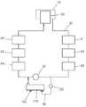
도 1은 본 발명의 일 실시예에 따른 플로우셀장치를 도시한 단면도이다.
도 2는 본 발명의 일 실시예에 따른 플로우셀장치에서 플로우셀부를 도시한 사시도이다.
도 3은 본 발명의 일 실시예에 따른 플로우셀장치가 적용되는 애칭장치를 도시한 블록도이다.
도 4는 본 발명의 일 실시예에 따른 플로우셀장치가 경사지게 설치된 상태를 개략적으로 도시한 도면이다.
도 5는 본 발명의 일 실시예에 따른 플로우셀장치가 실린더부에 의해 각도가 조절되는 상태를 개략적으로 도시한 도면이다.
도 6은 본 발명의 일 실시예에 따른 플로우셀장치가 적용되는 애칭장치를 도시한 블록도이다.
도 7은 본 발명의 일 실시예에 따른 플로우셀장치에서 유동매체의 농도를 측정하는 제1 방식을 도시한 그래프이다.
도 8은 본 발명의 일 실시예에 따른 플로우셀장치에서 유동매체의 농도를 측정하는 제2 방식을 도시한 그래프이다.1 is a cross-sectional view showing a flow cell device according to an embodiment of the present invention.
2 is a perspective view showing a flow cell unit in the flow cell device according to an embodiment of the present invention.
3 is a block diagram showing a nicking device to which a flow cell device according to an embodiment of the present invention is applied.
4 is a view schematically showing a state in which the flow cell device according to an embodiment of the present invention is installed obliquely.
5 is a view schematically showing a state in which the flow cell device according to an embodiment of the present invention is angle adjusted by the cylinder unit.
6 is a block diagram showing a nicking device to which a flow cell device according to an embodiment of the present invention is applied.
7 is a graph showing a first method of measuring the concentration of a flow medium in a flow cell device according to an embodiment of the present invention.
8 is a graph showing a second method of measuring the concentration of a flow medium in a flow cell device according to an embodiment of the present invention.
이하, 첨부된 도면들을 참조하여 본 발명에 따른 플로우셀장치의 일 실시예를 설명한다. 플로우셀장치를 설명하는 과정에서 도면에 도시된 선들의 두께나 구성요소의 크기 등은 설명의 명료성과 편의상 과장되게 도시되어 있을 수 있다. 또한, 후술되는 용어들은 본 발명에서의 기능을 고려하여 정의된 용어들로서 이는 사용자, 운용자의 의도 또는 관례에 따라 달라질 수 있다. 그러므로 이러한 용어들에 대한 정의는 본 명세서 전반에 걸친 내용을 토대로 내려져야 할 것이다.Hereinafter, an embodiment of a flow cell device according to the present invention will be described with reference to the accompanying drawings. In the process of describing the flow cell device, the thickness of the lines or the size of components shown in the drawings may be exaggerated for clarity and convenience. In addition, terms to be described later are terms defined in consideration of functions in the present invention, which may vary according to a user's or operator's intention or practice. Therefore, the definition of these terms should be made based on the contents throughout the present specification.
도 1은 본 발명의 일 실시예에 따른 플로우셀장치를 도시한 단면도이고, 도 2는 본 발명의 일 실시예에 따른 플로우셀장치에서 플로우셀부를 도시한 사시도이다.1 is a cross-sectional view showing a flow cell device according to an embodiment of the present invention, and FIG. 2 is a perspective view showing a flow cell unit in a flow cell device according to an embodiment of the present invention.
도 1 및 도 2를 참조하면, 본 발명의 일 실시예에 따른 플로우셀장치(100)는 하우징부(110), 플로우셀부(120), 제1 광학부(130) 및 제2 광학부(140)를 포함한다.1 and 2, the
하우징부(110)는 길이방햐을 따라 길게 형성된다. 하우징부(110)는 직사각 박스 형태로 형성될 수 있다. 하우징부(110)는 고온에서 열변형되는 것을 방지하도록 내열성 재질로 형성될 수 있다.The
플로우셀부(120)는 하우징부(110)에 수용되고, 유동매체가 유동되도록 유동통로부(122)가 형성된다. 유동통로부(122)의 단면은 유동매체의 저항을 감소시키도록 원형으로 형성된다. 유동매체는 반도체 웨이퍼나 태양광셀 등을 제조할 때에 반도체 공정에 사용되는 에칭용액일 수 있다. 에칭용액으로는 150-200℃의 인산용액일 수 있다. 플로우셀부(120)는 150-200℃ 정도의 유동매체에 의해 열변형 및 부식되는 것을 방지하도록 석영재질, 파이펙스 글라스 및 테프론 재질 등 중 어느 하나로 형성될 수 있다.The
플로우셀부(120)에는 유동매체에 함유된 물질이 석출되는 것을 억제하도록 150-200℃로 가열된 유동매체가 유동되므로, 플로우셀부(120)에는 고온의 유동매체의 파장이 광에 흡수되도록 고온의 유동매체가 유동될 수 있다.Since the flow medium heated to 150-200 ° C. flows in the
따라서, 유동매체가 실제의 반도체 공정에 사용되는 조건에서 유동매체의 농도를 측정하고, 유동매체의 검출 감도를 증가시키기 위해 유동매체를 복수 번에 걸쳐 화학처리 할 필요가 없다. 또한, 유동매체를 상온으로 냉각하지 않아도 되므로, 유동매체의 온도차에 의해 검출 오차가 발생되는 것을 방지하고, 실제 반도체 공정에서 적용되는 사용 조건에서 유동매체의 상태를 정확하게 예측할 수 있다. 또한, 농도 분석 중 매트릭스를 간단하게 만들어 분석 농도의 정확성을 향상시킬 수 있다.Therefore, it is not necessary to chemically process the flow medium multiple times in order to measure the concentration of the flow medium and increase the detection sensitivity of the flow medium under conditions in which the flow medium is used in an actual semiconductor process. In addition, since it is not necessary to cool the fluid medium to room temperature, it is possible to prevent a detection error from being generated due to a temperature difference of the fluid medium, and to accurately predict the state of the fluid medium under use conditions applied in an actual semiconductor process. In addition, it is possible to improve the accuracy of the analytical concentration by simply making the matrix during the concentration analysis.
제1 광학부(130)는 광원부(171)에서 조사되는 광을 플로우셀부(120)의 유동매체의 유동방향과 나란하게 조사하도록 하우징부(110)에 배치된다. 이때, 플로우셀부(120)에서 유동매체의 진행방향을 따라 광이 진행되므로, 광이 유동매체를 투과할 때에 기포나 용출물에 의해 산란 및 굴절되는 것을 최소화하여 광 손실을 감소시킬 수 있다. 또한, 광이 유동매체를 투과하면서 유동매체에 함유된 용출물의 파장을 원활하게 흡수할 수 있으므로, 광검출 효율이 향상될 수 있다.The first
제2 광학부(140)는 유동통로부(122)의 유동매체를 투과하면서 유동매체의 파장을 흡수하는 광을 광검출부(173)에 조사하도록 하우징부(110)에 배치된다.The second
플로우셀부(120)는 플로우셀 바디부(121), 공급관부(123) 및 배출관부(125)를 포함한다.The
플로우셀 바디부(121)는 하우징부(110)의 내부에 수용되고, 그 내부에 유동통로부(122)가 형성된다. 플로우셀 바디부(121)의 단면은 원형으로 형성된다. 플로우셀 바디부(121)의 단면이 원형으로 형성되므로, 유동통로부(122)를 따라 유동되는 유동매체의 유동 저항이 감소될 수 있다.The flow
공급관부(123)는 플로우셀 바디부(121)에 유동매체가 공급되도록 플로우셀 바디부(121)의 일측에 연결된다. 공급관부(123)의 단면은 유동매체의 유동 저항을 감소시키도록 원형으로 형성된다.The
배출관부(125)는 플로우셀 바디부(121)의 유동매체가 배출되도록 플로우셀 바디부(121)의 타측에 연결된다. 배출관부(125)의 단면은 유동매체의 유동 저항을 감소시키도록 원형으로 형성된다.The
공급관부(123)가 플로우셀 바디부(121)의 일측에 연결되고, 배출관부(125)가 플로우셀 바디부(121)의 타측에 연결되므로, 유동매체가 플로우셀 바디부(121)의 일측에서 플로우셀 바디부(121)의 타측으로 유동된다.Since the
공급관부(123)는 플로우셀 바디부(121)의 하측에 연결되고, 배출관부(125)는 플로우셀 바디부(121)의 상측에 연결된다. 이때, 유동매체에 함유된 기포의 비중은 유동매체의 비중 보다 가볍다.The
유입관부가 플로우셀부(120)의 하부에 연결되고, 배출관부(125)가 플로우셀부(120)의 상측에 연결되므로, 유동매체가 플로우셀부(120)의 하측에서 상측으로 유동된다. 또한, 유동매체에 함유된 기포는 대부분 플로우셀부(120)의 직경을 가로질러 유동된 후 플로우셀부(120)의 상측을 따라 유동되므로, 광이 플로우셀부(120)의 내부를 따라 유동될 때에 기포에 의해 광손실이 발생되는 것을 최소화할 수 있다.Since the inlet pipe portion is connected to the lower portion of the
공급관부(123)는 제1 공급관부(123a), 제2 공급관부(123b) 및 제3 공급관부(123c)를 포함한다.The
제1 공급관부(123a)에는 유동매체가 공급된다. 제1 공급관부(123a)는 플로우셀 바디부(121)의 일측에서 중심부 측으로 일정 간격 이격되게 배치된다.A fluid medium is supplied to the first
제2 공급관부(123b)는 제1 공급관부(123a)에서 공급되는 유동매체가 난류를 형성하도록 제1 공급관부(123a)의 직경보다 확관되게 형성된다. 제2 공급관부(123b)가 제1 공급관부(123a)의 직경보다 확관되므로, 제1 공급관부(123a)의 유동매체가 제2 공급관부(123b)에 유입될 때에 확산되면서 유속이 증가된다. 따라서, 제2 공급관부(123b)에서 유동매체가 난류를 형성함에 따라 유동매체에서 기포가 발생되는 것을 억제할 수 있다.The second
또한, 제2 공급관부(123b)의 직경은 제1 공급관부(123a)의 직경과 동일하게 형성될 수 있다.In addition, the diameter of the second
제3 공급관부(123c)는 제2 공급관부(123b)에서 연장되고, 플로우셀 바디부(121)의 길이방향과 경사지도록 플로우셀 바디부(121)의 일측에 연결된다. 이때, 제3 공급관부(123c)는 플로우셀 바디부(121)의 일측에서 플로우셀 바디부(121)의 타측을 향하여 하향으로 경사지게 형성된다. 제3 공급관부(123c)가 플로우셀 바디부(121)의 길이방향과 경사지게 플로우셀 바디부(121)에 연결되므로, 유동매체에 함유된 기포가 제3 공급관부(123c)의 상측을 따라 유동된 후 플로우셀 바디부(121)의 상측으로 유동된다. 따라서, 유동매체에 함유된 기포에 의해 광이 산란되거나 굴절되는 것을 최소화할 수 있다.The third
배출관부(125)는 플로우셀 바디부(121)의 상측에 수직하게 연장되는 제1 배출관부(125a)와, 제1 배출관부(125a)에서 플로우셀 바디부(121)의 길이방향과 수직하게 연장되는 제2 배출관부(125b)를 포함한다. 제1 배출관부(125a)의 직경은 플로우셀 바디부(121)의 직경과 동일하거나 거의 동일하게 형성된다. 제1 배출관부(125a)가 플로우셀 바디부(121)의 상측에 수직하게 연장되므로, 플로우셀 바디부(121)에서 배출되는 유동매체가 압력차에 의해 제1 배출관부(125a)의 하측으로 역류되는 것을 최소화할 수 있다.The
제1 광학부(130)는 유동매체의 유동방향과 나란하게 광을 조사하도록 플로우셀 바디부(121)의 일측에 배치된다. 플로우셀 바디부(121)에서 유동매체의 진행방향을 따라 광이 진행되므로, 광이 유동매체를 투과할 때에 기포나 용출물에 의해 산란 및 굴절되는 것을 최소화하여 광 손실을 감소시킬 수 있다. 또한, 광이 유동매체를 투과하면서 유동매체에 함유된 용출물의 파장을 원활하게 흡수할 수 있으므로, 광검출 효율이 향상될 수 있다.The first
제1 광학부(130), 플로우셀 바디부(121) 및 제2 광학부(140)는 대응되게 배치된다. 따라서, 제1 광학부(130)에서 조사되는 광이 플로우셀 바디부(121) 및 제2 광학부(140)를 통해 일직선을 따라 진행될 수 있다.The first
제1 광학부(130)는 제1 광학 슬라이더부(131), 제1 반사거울(133) 및 제1 위치 조절부(135)를 포함한다. 제1 광학 슬라이더부(131)는 플로우셀 바디부(121)의 일측에 배치된다. 제1 광학 슬라이더부(131)는 이동 가능하게 설치된다. 제1 반사거울(133)은 광원부(171)에서 입사되는 광을 플로우셀 바디부(121)의 유동매체에 조사하도록 제1 광학 슬라이더부(131)에 배치된다. 제1 반사거울(133)은 대략 45° 정도 경사지게 배치된다. 제1 위치조절부(135)는 제1 반사거울(133)의 위치를 조절하도록 제1 광학 슬라이더부(131)에 설치된다. 제1 위치조절부(135)는 제1 반사거울(133)의 위치를 조절하도록 제1 광학 슬라이더부(131)에 설치된다. 제1 위치조절부(135)는 나사 형태로 형성될 수 있다. 제1 위치 조절부(135)가 회전됨에 따라 제1 광학 슬라이더부(131)와 제1 반사거울(133)이 이동된다.The first
제2 광학부(140)는 제2 광학 슬라이더부(141), 제2 반사거울(143) 및 제2 위치 조절부(145)를 포함한다. 제2 광학 슬라이더부(141)는 플로우셀 바디부(121)의 타측에 배치된다. 제2 광학 슬라이더부(141)는 이동 가능하게 설치된다. 제2 반사거울(143)은 광원부(171)에서 입사되는 광을 플로우셀 바디부(121)의 유동매체에 조사하도록 제2 광학 슬라이더부(141)에 배치된다. 제2 반사거울(143)은 대략 45° 정도 경사지게 배치된다. 제2 위치조절부(145)는 제2 반사거울(143)의 위치를 조절하도록 제2 광학 슬라이더부(141)에 설치된다. 제2 위치조절부(145)는 제2 반사거울(143)의 위치를 조절하도록 제2 광학 슬라이더부(141)에 설치된다. 제2 위치조절부(145)는 나사 형태로 형성될 수 있다. 제2 위치 조절부(145)가 회전됨에 따라 제2 광학 슬라이더부(141)와 제2 반사거울(143)이 이동된다.The second
플로우셀장치(100)는 플로우셀부(120)의 외측면을 탄성 지지하도록 하우징부(110)에 설치되는 탄성 가압부(114)를 더 포함한다. 탄성 가압부(114)는 플로우셀부(120)의 외측면을 탄성 지지하면서 플로우셀부(120)의 경사 각도를 조절하도록 설치된다. 탄성 가압부(114)는 플로우셀부(120)의 외측면을 지지하는 가압 로드부(114a)와, 가압 로드부(114a)를 플로우셀부(120) 측으로 이동시키도록 설치되는 탄성부재(114b)를 포함한다. 탄성 가압부(114)는 플로우셀부(120)의 길이방향을 따라 복수 개가 배치된다. 탄성 가압부(114)가 플로우셀부(120)의 외측면을 탄성 지지하므로, 플로우셀부(120)가 유동매체의 온도에 의해 팽창하거나 수축되더라도 탄성 가압부(114)가 플로우셀부(120)를 안정적으로 지지할 수 있다. 따라서, 플로우셀부(120)가 팽창 및 수축할 때에 하우징부(110)에 의해 피가압되어 손상되는 것을 방지할 수 있다.The
하우징부(110)의 내부에는 플로우셀부(120)의 팽창 공간을 허용하도록 이격공간부(112)가 형성된다. 따라서, 플로우셀부(120)가 유동매체에 의해 팽창 및 수축되더라도 하우징부(110)에 눌려 손상되는 것을 방지할 수 있다.A spaced
플로우셀장치(100)는 제1 광학부(130)에 대향되고, 제1 광섬유부(154)가 연결되는 제1 컬리메이터부(150)와, 제2 광학부(140)에 대향되고, 제2 광섬유부(164)가 연결되는 제2 컬리메이터부(160)를 더 포함한다.The
제1 컬리메이터부(150)는 광원부(171)에서 조사되는 광을 평행하게 시준(collimating)한다. 제1 컬리메이터부(150)에서 광을 평행하게 시준하므로, 플로우셀부(120)에는 제1 광원부(171)에 의해 광이 평행하게 입사된다. 제1 컬리메이터부(150)에는 위치를 조절할 있도록 제1 조절 나사부(152)가 설치된다.The
제1 광섬유부(154)가 광원부(171)와 제1 컬리메이터부(150)에 연결되므로, 광원부(171)가 플로우셀부(120)와 이격되게 설치될 수 있다. 150-200℃ 정도의 고온의 유동매체가 플로우셀부(120)를 통과하므로, 플로우셀부(120)가 고온의 유동매체에 의해 가열된다. 광원부(171)와 광검출부(173)가 제1 광섬유부(154)에 의해 플로우셀부(120)와 이격되게 설치되므로, 광원부(171)가 플로우셀부(120)의 열기에 의해 과열되는 것을 방지할 수 있다. 또한, 광원부(171)를 냉각시키거나 단열시키기 위해 별도의 냉각장치나 단열부재를 설치하지 않아도 된다.Since the first
제2 컬리메이터부(160)는 플로우셀 바디부(121)에서 조사되는 광을 평행하게 시준한다. 광이 제2 컬리메이터부(160)를 투과하면서 평행하게 시준되므로, 광검출부(173)에서 검출 효율이 향상될 수 있다. 제2 컬리메이터부(160)에는 위치를 조절할 있도록 제2 조절 나사부(162)가 설치된다.The
제2 광섬유부(164)가 광검출부(173)와 제2 컬리메이터부(160)에 연결되므로, 광검출부(173)가 플로우셀부(120)와 이격되게 설치될 수 있다. 150-200℃ 정도의 고온의 유동매체가 플로우셀부(120)를 통과하므로, 플로우셀부(120)가 고온의 유동매체에 의해 가열된다. 광검출부(173)가 제2 광섬유부(164)에 의해 플로우셀부(120)와 이격되게 설치되므로, 광검출부(173)가 플로우셀부(120)의 열기에 의해 과열되는 것을 방지할 수 있다. 또한, 광검출부(173)를 냉각시키거나 단열시키기 위해 별도의 냉각장치나 단열부재를 설치하지 않아도 된다.Since the second
플로우셀부(120)의 양측에 제1 광섬유부(154)와 제2 광섬유부(164)가 설치되므로, 플로우셀부(120), 광원부(171) 및 광검출부(173)를 일렬로 배열해야 하지 않아도 된다. 따라서, 플로우셀장치(100)의 설치 자유도를 증가시킬 수 있다.Since the first
상기와 같은 플로우셀장치가 적용된 에칭장치에 관해 설명하기로 한다.An etching apparatus to which the above flow cell apparatus is applied will be described.
도 3은 본 발명의 일 실시예에 따른 플로우셀장치가 적용되는 애칭장치를 도시한 블록도이고, 도 4는 본 발명의 일 실시예에 따른 플로우셀장치가 경사지게 설치된 상태를 개략적으로 도시한 도면이다.3 is a block diagram showing a nicking device to which a flow cell device according to an embodiment of the present invention is applied, and FIG. 4 is a schematic view showing a state in which the flow cell device according to an embodiment of the present invention is installed obliquely to be.
도 3 내지 도 5를 참조하면, 에칭장치는 외조(10)와 내조(20)를 포함한다. 내조(20)와 외조(10)는 순환유로부(30)에 연결된다. 순환유로부(30)에는 펌프(41), 댐퍼(42), 필터부(43), 메인 밸브(32), 히터부(44), 버블커터(45) 및 농도 측정부(46)가 순차적으로 설치된다.3 to 5, the etching apparatus includes an
내조(20)에 수용되는 유동매체는 외조(10)에 오버 플로우(over flow) 된다. 외조(10)의 유동매체는 펌프(41)에 의해 댐퍼(42)에 유동되고, 필터부(43)는 유입되는 유동매체를 여과한다. 필터부(43)에서 여과된 유동매체는 메인 밸브(32)를 통해 히터부(44)에 유동되고, 히터부(44)에서 가열된다. 히터부(44)에서 가열된 유동매체는 버블커터(45)에 의해 기포가 제거되고, 농도 측정부(46)는 인산용액의 농도를 측정한다.The flow medium accommodated in the
순환유로부(30)에는 바이패스 유로부(35)가 연결된다. 바이패스 유로부(35)는 필터부(43)의 토출측과 히터부(44)의 유입측을 연결한다. 순환유로부(30)를 따라 유동되는 고온의 유동매체는 바이패스 유로부(35)를 통해 플로우셀장치(100)에 공급된다. 플로우셀장치(100)에서는 유동매체의 농도를 측정한 후 순환유로부(30)에 유동매체가 회수된다.The bypass
또한, 플로우셀장치(100)는 순환유로부(30) 상에 직접 설치될 수 있다. 이때, 순환유로부(30)에는 바이패스 유로부가 형성되지 않는다. 이 경우, 순환유로부(30)를 따라 유동되는 유동매체의 농도를 플로우셀장치(100)에 의해 직접 측정할 수 있다.Also, the
플로우셀장치(100)에는 유동매체에 함유된 물질이 석출되는 것을 억제하도록 150-200℃로 가열된 유동매체가 유동된다. 또한, 플로우셀장치(100)에는 가열된 유동매체의 파장이 광에 흡수되도록 고온의 유동매체가 유동될 수 있다.In the
따라서, 유동매체가 실제의 반도체 공정에 사용되는 조건에서 유동매체의 농도를 측정하고, 유동매체의 검출 감도를 증가시키기 위해 유동매체를 복수 번에 걸쳐 화학처리 할 필요가 없다. 또한, 유동매체를 상온으로 냉각하지 않아도 되므로, 유동매체의 온도차에 의해 검출 오차가 발생되는 것을 방지하고, 실제 반도체 공정에서 적용되는 사용 조건에서 유동매체의 상태를 정확하게 예측할 수 있다. 또한, 농도 분석 중 매트릭스를 간단하게 만들어 분석 농도의 정확성을 향상시킬 수 있다.Therefore, it is not necessary to chemically process the flow medium multiple times in order to measure the concentration of the flow medium and increase the detection sensitivity of the flow medium under conditions in which the flow medium is used in an actual semiconductor process. In addition, since it is not necessary to cool the fluid medium to room temperature, it is possible to prevent a detection error from being generated due to a temperature difference of the fluid medium, and to accurately predict the state of the fluid medium under use conditions applied in an actual semiconductor process. In addition, it is possible to improve the accuracy of the analytical concentration by simply making the matrix during the concentration analysis.
또한, 플로우셀장치(100)에서 플로우셀부(120)는 공급관부(123) 측(일측)에서 배출관부(125) 측(타측)으로 갈수록 상향으로 일정 각도(θ) 경사지게 배치될 수 있다. 플로우셀부(120)가 유동매체의 배출측으로 상향으로 경사지게 배치되므로, 유동매체에 함유된 기포가 플로우셀부(120)의 상측을 따라 유동된다. 따라서, 광이 플로우셀부(120)의 내부를 따라 유동될 때에 기포에 의해 광손실이 발생되는 것을 최소화할 수 있다.In addition, in the
또한, 플로우셀장치(100)는 하우징부(110) 또는 플로우셀부(120)는 경사 각도를 조절하도록 설치되는 각도 조절부(103)를 더 포함할 수 있다(도 5 참조). 각도 조절부(103)로는 실린더부, 기어부, 랙피니언 구조 등 다양한 형태가 적용될 수 있다. 각도 조절부(103)가 구동됨에 따라 플로우셀장치(100)의 각도(θ)가 조절되므로, 유동매체에 함유된 기포가 플로우셀부(120)의 상측을 따라 원활하게 유동되도록 플로우장치의 각도를 최적으로 조절할 수 있다.In addition, the
도 6은 본 발명의 일 실시예에 따른 플로우셀장치(100)가 적용되는 애칭장치를 도시한 블록도이다.6 is a block diagram showing a nicking device to which the
도 6을 참조하면, 에칭장치는 외조(10)와 내조(20)를 포함한다. 내조(20)와 외조(10)는 순환유로부(30)에 연결된다. 순환유로부(30)에는 펌프(41), 댐퍼(42), 필터부(43), 메인 밸브(32), 히터부(44), 버블커터(45) 및 농도 측정부(46)가 순차적으로 설치된다.Referring to FIG. 6, the etching apparatus includes an
순환유로부(30)에는 드레인관부(38)가 연결된다. 드레인관부(38)에는 드레인 밸브(39)와 플로우셀장치(100)가 설치된다. 드레인 밸브(39)가 개강됨에 따라 플로우셀장치(100)에 유동매체가 유입되고, 플로우셀장치(100)에서 유동매체의 농도가 측정된다. 플로우셀장치(100)에 배출되는 유동매체는 드레인관부(38)를 통해 에칭장치의 외부로 배출된다.A
다음으로, 플로우셀장치에서 웨이퍼의 교체 시기를 판단하는 방법에 관해 설명하기로 한다.Next, a method of determining when to replace the wafer in the flow cell device will be described.
도 7은 본 발명의 일 실시예에 따른 플로우셀장치에서 유동매체의 농도를 측정하는 제1 방식을 도시한 그래프이다.7 is a graph showing a first method of measuring the concentration of a flow medium in a flow cell device according to an embodiment of the present invention.
도 7을 참조하면, 플로우장치에서 유동매체의 농도가 측정된다. 웨이퍼가 에칭됨에 따라 웨이퍼에서 용출물이 계속적으로 용출된다. 에칭장치에서 웨이퍼가 1차 에칭될 때의 유동매체의 농도를 계속적으로 측정하면, 유동매체의 농도가 증가하다가 정체되는 구간이 발생된다. 이렇게 정체되는 구간을 1차 엔딩 포인트로 판단하고 웨이퍼를 교체한다. 1차 에칭 공정이 완료되면, 2차 에칭 공정을 수행한다. 2차 에칭 공정에서도 유동매체의 농도가 증가하다가 정체되는 구간이 발생되면 2차 에칭된 웨이퍼를 교체한다. 따라서, 유동매체가 실제의 반도체 공정에 사용되는 조건에서 유동매체의 농도를 측정하므로, 유동매체의 상태와 웨이퍼의 교환 시기를 정확하게 판단할 수 있다.Referring to FIG. 7, the concentration of the flow medium in the flow device is measured. As the wafer is etched, the eluate continues to elute from the wafer. If the concentration of the fluid medium is continuously measured when the wafer is first etched in the etching apparatus, a section where the concentration of the fluid medium increases and becomes stagnant occurs. The stagnant section is determined as the primary ending point and the wafer is replaced. When the primary etching process is completed, a secondary etching process is performed. In the secondary etching process, when the concentration of the fluid medium increases and a stagnant section occurs, the secondary etched wafer is replaced. Accordingly, since the concentration of the fluid medium is measured under the conditions in which the fluid medium is used in the actual semiconductor process, it is possible to accurately determine the state of the fluid medium and the timing of wafer exchange.
도 8은 본 발명의 일 실시예에 따른 플로우셀장치에서 유동매체의 농도를 측정하는 제2 방식을 도시한 그래프이다.8 is a graph showing a second method of measuring the concentration of a flow medium in a flow cell device according to an embodiment of the present invention.
도 8을 참조하면, 에칭장치에서 웨이퍼가 1차 에칭될 때의 유동매체의 농도를 계속적으로 측정하면, 유동매체의 농도가 증가하다가 정체되는 구간이 발생된다. 이렇게 정체되는 구간을 1차 엔딩 포인트로 판단하고 웨이퍼를 교체한다. 웨이퍼를 교체한 후 1차 엔딩 포인트 값을 초기화 시킨다. 초기화된 값을 시작으로 2차 에칭 공정이 수행된다. 2차 에칭 공정에서도 유동매체의 농도가 증가하다가 정체되는 구간이 발생되면 2차 에칭된 웨이퍼를 교체한다. 웨이퍼를 교체한 후 2차 엔딩 포인트 값을 초기화 시킨다. 이러한 과정을 통해 웨이퍼의 교체 시기를 예측할 수 있다. 따라서, 유동매체가 실제의 반도체 공정에 사용되는 조건에서 유동매체의 농도를 측정하므로, 유동매체의 상태와 웨이퍼의 교환 시기를 정확하게 판단할 수 있다.Referring to FIG. 8, if the concentration of the fluid medium when the wafer is first etched is continuously measured in the etching apparatus, a concentration period of the fluid medium increases and stagnation occurs. The stagnant section is determined as the primary ending point and the wafer is replaced. After replacing the wafer, the primary ending point value is initialized. The secondary etching process is performed starting from the initialized value. In the secondary etching process, when the concentration of the fluid medium increases and a stagnant section occurs, the secondary etched wafer is replaced. After replacing the wafer, the secondary ending point value is initialized. Through this process, it is possible to predict the timing of wafer replacement. Accordingly, since the concentration of the fluid medium is measured under the conditions in which the fluid medium is used in the actual semiconductor process, it is possible to accurately determine the state of the fluid medium and the timing of wafer exchange.
본 발명은 도면에 도시된 실시예를 참고로 하여 설명되었으나, 이는 예시적인 것에 불과하며, 당해 기술이 속하는 분야에서 통상의 지식을 가진 자라면 이로부터 다양한 변형 및 균등한 타 실시예가 가능하다는 점을 이해할 것이다.The present invention has been described with reference to the embodiment shown in the drawings, but this is merely exemplary, and those skilled in the art to which the art belongs can various modifications and equivalent other embodiments from this. Will understand.
따라서, 본 발명의 진정한 기술적 보호범위는 청구범위에 의해서 정하여져야 할 것이다.Therefore, the true technical protection scope of the present invention should be defined by the claims.
10: 외조20: 내조
30: 순환유로부32: 메인 밸브
35: 바이패스 유로부36: 바이패스 밸브
38: 드레인관부39: 드레인 밸브
41: 펌프42: 댐퍼
43: 필터부44: 히터부
45: 버블커터46: 농도 측정부
100: 플로우셀장치110: 하우징부
112: 이격 공간부114: 탄성 가압부
114a: 가압 로드부114b: 탄성부재
120: 플로우셀부121: 플로우셀 바디부
123: 공급관부123a: 제1 공급관부
123b: 제2 공급관부123c: 제3 공급관부
125: 배출관부125a: 제1 배출관부
125b: 제2 배출관부130: 제1 광학부
131: 제1 광학 슬라이더부133: 제1 반사거울
135: 제1 위치 조절부140: 제2 광학부
141: 제2 광학 슬라이더부143: 제2 반사거울
145: 제2 위치 조절부150: 제1 컬리메이터부
152: 제1 조절 나사부154: 제1 광섬유부
160: 제2 컬리메이터부162: 제2 조절 나사부
164: 제2 광섬유부171: 광원부
173: 광검출부10: foreign language 20: internal tone
30: circulation flow passage 32: main valve
35: bypass flow path part 36: bypass valve
38: drain pipe 39: drain valve
41: pump 42: damper
43: filter unit 44: heater unit
45: bubble cutter 46: concentration measurement unit
100: flow cell device 110: housing
112: spaced apart portion 114: elastic pressing portion
114a: Pressing
120: flow cell portion 121: flow cell body portion
123:
123b: 2nd
125:
125b: second discharge pipe portion 130: first optical portion
131: first optical slider unit 133: first reflective mirror
135: first position adjusting unit 140: second optical unit
141: second optical slider portion 143: second reflective mirror
145: second position adjustment unit 150: first collimator unit
152: first adjustment screw portion 154: first optical fiber portion
160: second collimator portion 162: second adjustment screw portion
164: second optical fiber unit 171: light source unit
173: photodetector
Claims (17)
Translated fromKorean상기 하우징부에 수용되고, 유동매체가 유동되도록 유동통로부가 형성되는 플로우셀부;
광원부에서 조사되는 광을 상기 플로우셀부의 유동매체의 유동방향과 나란하게 조사하도록 상기 하우징부에 배치되는 제1 광학부; 및
상기 유동통로부의 유동매체를 투과하면서 유동매체의 파장이 흡수되는 광을 광검출부에 광을 조사하도록 상기 하우징부에 배치되는 제2 광학부를 포함하는 것을 특징으로 하는 플로우셀장치.
Housing part;
A flow cell part accommodated in the housing part and formed with a flow passage part so that the flow medium flows;
A first optical unit disposed in the housing unit to irradiate light emitted from the light source unit in parallel with the flow direction of the flow medium of the flow cell unit; And
And a second optical unit disposed in the housing unit so as to irradiate the light to the photodetector with light absorbed by the wavelength of the fluid medium while passing through the fluid medium of the flow passage unit.
상기 플로우셀부는,
상기 하우징부의 내부에 수용되고, 상기 유동통로부가 형성되는 플로우셀 바디부;
상기 플로우셀 바디부에 유동매체가 공급되도록 상기 플로우셀 바디부의 일측에 연결되는 공급관부; 및
상기 플로우셀 바디부의 유동매체가 배출되도록 상기 플로우셀 바디부의 타측에 연결되는 배출관부를 포함하는 것을 특징으로 하는 플로우셀장치.
According to claim 1,
The flow cell unit,
A flow cell body part accommodated in the housing part and in which the flow passage part is formed;
A supply pipe part connected to one side of the flow cell body so that a flow medium is supplied to the flow cell body; And
And a discharge pipe part connected to the other side of the flow cell body part so that the flow medium of the flow cell body part is discharged.
상기 공급관부는 상기 플로우셀 바디부의 하측에 연결되고,
상기 배출관부는 상기 플로우셀 바디부의 상측에 연결되는 것을 특징으로 하는 플로우셀장치.
According to claim 2,
The supply pipe portion is connected to the lower side of the flow cell body portion,
The discharge pipe unit is a flow cell device, characterized in that connected to the upper side of the flow cell body.
상기 공급관부는,
유동매체가 공급되는 제1 공급관부;
상기 제1 공급관부에서 공급되는 유동매체가 난류를 형성하도록 상기 제1 공급관부의 직경보다 크게 형성되는 제2 공급관부; 및
상기 제2 공급관부에서 연장되고, 상기 플로우셀 바디부의 길이방향과 경사지도록 상기 플로우셀 바디부의 일측에 연결되는 제3 공급관부를 포함하는 것을 특징으로 하는 플로우셀장치.
According to claim 3,
The supply pipe portion,
A first supply pipe part through which a fluid medium is supplied;
A second supply pipe portion formed larger than the diameter of the first supply pipe portion so that the flow medium supplied from the first supply pipe portion forms turbulence; And
And a third supply pipe part extending from the second supply pipe part and connected to one side of the flow cell body part so as to be inclined with a longitudinal direction of the flow cell body part.
상기 제3 공급관부는 상기 플로우셀 바디부의 일측에서 상기 플로우셀 바디부의 타측을 향하여 하향으로 경사지게 형성되는 것을 특징으로 하는 플로우셀장치.
According to claim 4,
The third supply pipe portion is a flow cell device, characterized in that formed in an inclined downward toward the other side of the flow cell body portion from one side of the flow cell body portion.
상기 배출관부는,
상기 플로우셀 바디부의 상측에 수직하게 연장되는 제1 배출관부; 및
상기 제1 배출관부에서 상기 플로우셀 바디부의 길이방향과 수직하게 연장되는 제2 배출관부를 포함하는 것을 특징으로 하는 플로우셀장치.
According to claim 4,
The discharge pipe portion,
A first discharge pipe part extending perpendicular to an upper side of the flow cell body part; And
And a second discharge pipe portion extending perpendicularly to the longitudinal direction of the flow cell body portion from the first discharge pipe portion.
상기 제1 광학부는 유동매체의 유동방향과 나란하게 광을 조사하도록 상기 플로우셀 바디부의 일측에 배치되는 것을 특징으로 하는 플로우셀장치.
According to claim 2,
The first optical unit is a flow cell device, characterized in that arranged on one side of the flow cell body portion to irradiate light in parallel with the flow direction of the flow medium.
상기 제1 광학부, 상기 플로우셀 바디부 및 상기 제2 광학부는 대응되게 배치되는 것을 특징으로 하는 플로우셀장치.
The method of claim 7,
The first optical unit, the flow cell body portion and the second optical unit is a flow cell device, characterized in that disposed correspondingly.
상기 제1 광학부는,
상기 플로우셀 바디부의 일측에 배치되는 제1 광학 슬라이더부;
상기 광원부에서 입사되는 광을 상기 플로우셀 바디부의 유동매체에 조사하도록 상기 제1 광학 슬라이더부에 배치되는 제1 반사거울; 및
상기 제1 반사거울의 위치를 조절하도록 상기 제1 광학 슬라이더부에 설치되는 제1 위치조절부를 포함하는 것을 특징으로 하는 플로우셀장치.
The method of claim 7,
The first optical unit,
A first optical slider portion disposed on one side of the flow cell body portion;
A first reflection mirror disposed on the first optical slider unit to irradiate light flowing from the light source unit to the flow medium of the flow cell body unit; And
And a first position adjustment unit installed in the first optical slider unit to adjust the position of the first reflection mirror.
상기 제2 광학부는,
상기 플로우셀 바디부의 타측에 배치되는 제2 광학 슬라이더부;
상기 플로우셀 바디부의 유동매체의 파장을 흡수한 광을 상기 광검출부에 조사하도록 상기 제2 광학 슬라이더부에 배치되는 제2 반사거울; 및
상기 제2 반사거울의 위치를 조절하도록 상기 제2 광학 슬라이더부에 설치되는 제2 위치조절부를 포함하는 것을 특징으로 하는 플로우셀장치.
The method of claim 9,
The second optical unit,
A second optical slider portion disposed on the other side of the flow cell body portion;
A second reflection mirror disposed on the second optical slider to irradiate light absorbing the wavelength of the flow medium of the flow cell body portion to the photodetector; And
And a second position adjustment unit installed in the second optical slider unit to adjust the position of the second reflection mirror.
상기 플로우셀부의 외측면을 탄성 지지하도록 상기 하우징부에 설치되는 탄성 가압부를 더 포함하는 것을 특징으로 하는 플로우셀장치.
According to claim 1,
And an elastic pressing portion installed in the housing portion to elastically support the outer surface of the flow cell portion.
상기 탄성 가압부는 상기 플로우셀부의 외측면을 탄성 지지하면서 상기 플로우셀부의 경사 각도를 조절하는 것을 특징으로 하는 플로우셀장치.
The method of claim 11,
The elastic pressing portion is a flow cell device, characterized in that for adjusting the inclination angle of the flow cell portion while elastically supporting the outer surface of the flow cell portion.
상기 하우징부의 내부에는 상기 플로우셀부의 팽창 공간을 허용하도록 이격 공간부가 형성되는 것을 특징으로 하는 플로우셀장치.
The method of claim 11,
A flow cell device, characterized in that a space portion is formed inside the housing portion to allow an expansion space of the flow cell portion.
상기 탄성 가압부는 상기 플로우셀부의 길이방향을 따라 복수 개가 배치되는 것을 특징으로 하는 플로우셀장치.
The method of claim 13,
A flow cell device, characterized in that a plurality of the elastic pressing portions are arranged along the longitudinal direction of the flow cell portion.
상기 제1 광학부에 대향되고, 제1 광섬유부가 연결되는 제1 컬리메이터부; 및
상기 제2 광학부에 대향되고, 제2 광섬유부가 연결되는 제2 컬리메이터부를 더 포함하는 것을 특징으로 하는 플로우셀장치.
According to claim 1,
A first collimator unit facing the first optical unit and connected to a first optical fiber unit; And
And a second collimator part facing the second optical part and connected to the second optical fiber part.
상기 플로어셀부는 공급관부 측에서 배출관부 측으로 상향으로 경사지게 배치되는 것을 특징으로 하는 플로우셀장치.
According to claim 1,
The flow cell device, characterized in that the floor cell portion is arranged inclined upward from the supply pipe side to the discharge pipe side.
상기 플로어셀부의 경사 각도를 조절하도록 상기 플로어셀부 또는 상기 하우징부에 설치되는 각도 조절부를 더 포함하는 것을 특징으로 하는 플로우셀장치.
According to claim 1,
A flow cell device further comprising an angle adjustment unit installed in the floor cell unit or the housing unit to adjust the inclination angle of the floor cell unit.
Priority Applications (5)
| Application Number | Priority Date | Filing Date | Title |
|---|---|---|---|
| US17/268,158US12013327B2 (en) | 2018-09-20 | 2020-03-20 | Flow cell device |
| KR1020217016064AKR102531525B1 (en) | 2018-09-20 | 2020-03-20 | flow cell device |
| TW109109454ATWI784250B (en) | 2018-09-20 | 2020-03-20 | flow cell device |
| CN202080004011.0ACN112654852B (en) | 2018-09-20 | 2020-03-20 | Flow cell device |
| PCT/KR2020/003823WO2020230996A1 (en) | 2018-09-20 | 2020-03-20 | Flow cell device |
Applications Claiming Priority (2)
| Application Number | Priority Date | Filing Date | Title |
|---|---|---|---|
| KR20180113038 | 2018-09-20 | ||
| KR1020180113038 | 2018-09-20 |
Publications (1)
| Publication Number | Publication Date |
|---|---|
| KR20200034564Atrue KR20200034564A (en) | 2020-03-31 |
Family
ID=70002293
Family Applications (4)
| Application Number | Title | Priority Date | Filing Date |
|---|---|---|---|
| KR1020190055828APendingKR20200034564A (en) | 2018-09-20 | 2019-05-13 | Flow cell apparatus |
| KR1020190055827APendingKR20200034563A (en) | 2018-09-20 | 2019-05-13 | Monitoring apparatus of flow media |
| KR1020217016065AActiveKR102580490B1 (en) | 2018-09-20 | 2020-03-20 | Fluid media monitoring device |
| KR1020217016064AActiveKR102531525B1 (en) | 2018-09-20 | 2020-03-20 | flow cell device |
Family Applications After (3)
| Application Number | Title | Priority Date | Filing Date |
|---|---|---|---|
| KR1020190055827APendingKR20200034563A (en) | 2018-09-20 | 2019-05-13 | Monitoring apparatus of flow media |
| KR1020217016065AActiveKR102580490B1 (en) | 2018-09-20 | 2020-03-20 | Fluid media monitoring device |
| KR1020217016064AActiveKR102531525B1 (en) | 2018-09-20 | 2020-03-20 | flow cell device |
Country Status (5)
| Country | Link |
|---|---|
| US (2) | US11674875B2 (en) |
| KR (4) | KR20200034564A (en) |
| CN (2) | CN112654852B (en) |
| TW (2) | TWI784250B (en) |
| WO (2) | WO2020230996A1 (en) |
Families Citing this family (2)
| Publication number | Priority date | Publication date | Assignee | Title |
|---|---|---|---|---|
| CN119164882A (en)* | 2024-09-24 | 2024-12-20 | 无锡迅杰光远科技有限公司 | A corrosion-resistant liquid detection flow cell |
| KR102787937B1 (en)* | 2024-09-26 | 2025-03-31 | (주)휴마스 | Photometric water quality measurement device using a variable slit and a multi-stage measuring cell with variable optical path length |
Family Cites Families (58)
| Publication number | Priority date | Publication date | Assignee | Title |
|---|---|---|---|---|
| CH452233A (en)* | 1964-10-08 | 1968-05-31 | Ceskoslovenska Akademie Ved | Flow photometer arrangement |
| DE1598269A1 (en) | 1965-05-27 | 1971-12-23 | Ceskoslovenska Akademie Ved | Cell for flow photometer |
| US3514210A (en)* | 1968-01-15 | 1970-05-26 | Jiri Hrdina | Device for programmed drawing off of gas bubbles from a measuring cell separator and the liquid from the extinction cell space |
| US4368047A (en)* | 1981-04-27 | 1983-01-11 | University Of Utah Research Foundation | Process for conducting fluorescence immunoassays without added labels and employing attenuated internal reflection |
| US4663961A (en)* | 1985-09-17 | 1987-05-12 | Westinghouse Electric Corp. | System for remote chemical analysis |
| EP0327588B1 (en)* | 1986-11-26 | 1993-05-19 | RUSHBROOKE, John | High sensitivity optical imaging apparatus |
| JPH02212742A (en)* | 1989-02-13 | 1990-08-23 | Kowa Co | Liquid particulate measuring device |
| US5242586A (en)* | 1990-12-17 | 1993-09-07 | Biotage Inc. | Column protection system for liquid chromatography system |
| JP2552940Y2 (en)* | 1992-07-18 | 1997-11-05 | 株式会社堀場製作所 | Particle measurement device |
| KR100196198B1 (en)* | 1995-09-30 | 1999-06-15 | 가시마 쥰이치로 | Coriolis flowmeter |
| JPH10300671A (en)* | 1997-04-22 | 1998-11-13 | Yokogawa Electric Corp | Particle measurement device |
| US6082205A (en)* | 1998-02-06 | 2000-07-04 | Ohio State University | System and device for determining particle characteristics |
| CN1339610A (en)* | 2001-10-09 | 2002-03-13 | 张添 | Time-resolved fluorescnet detection method and detector for gene chip |
| US6854522B2 (en) | 2002-09-23 | 2005-02-15 | Halliburton Energy Services, Inc. | Annular isolators for expandable tubulars in wellbores |
| WO2004040717A2 (en)* | 2002-10-28 | 2004-05-13 | University Of Washington | Wavelength tunable surface plasmon resonance sensor |
| US20060182664A1 (en)* | 2005-02-14 | 2006-08-17 | Peck Bill J | Flow cell devices, systems and methods of using the same |
| GB0524225D0 (en)* | 2005-11-29 | 2006-01-04 | Amersham Biosciences Ab | Methods and apparatus for detecting and measuring the concentration of a substance in a solution |
| US7547904B2 (en)* | 2005-12-22 | 2009-06-16 | Palo Alto Research Center Incorporated | Sensing photon energies emanating from channels or moving objects |
| CN100419406C (en) | 2006-03-31 | 2008-09-17 | 洪陵成 | Flow-thru tank of flow photometric analyzing |
| JP4964647B2 (en)* | 2007-03-30 | 2012-07-04 | ジーエルサイエンス株式会社 | Fluorescence detection device |
| JP2009002806A (en)* | 2007-06-21 | 2009-01-08 | Hitachi Ltd | Chemiluminescence measuring device |
| US20090139311A1 (en)* | 2007-10-05 | 2009-06-04 | Applied Biosystems Inc. | Biological Analysis Systems, Devices, and Methods |
| JP2009162592A (en)* | 2007-12-28 | 2009-07-23 | Nippon Applied Technology Inc | Micro luminescence analyzer |
| JP5190945B2 (en)* | 2008-07-14 | 2013-04-24 | 富士フイルム株式会社 | Detection method, detection apparatus, detection sample cell, and detection kit |
| JP5066110B2 (en)* | 2009-01-30 | 2012-11-07 | 株式会社日立ハイテクノロジーズ | Fluorescence analyzer and fluorescence analysis method |
| JP2010217031A (en)* | 2009-03-17 | 2010-09-30 | Shimadzu Corp | Optical gas analysis system and gas flow cell |
| CN101634748A (en)* | 2009-08-27 | 2010-01-27 | 上海交通大学 | Weak-luminescence and fluorescence optical imaging device and imaging method thereof |
| DE102009059684A1 (en) | 2009-12-19 | 2011-06-22 | J. Eberspächer GmbH & Co. KG, 73730 | Exhaust gas treatment device |
| KR101213059B1 (en)* | 2011-02-23 | 2012-12-18 | 광운대학교 산학협력단 | System of measuring solar cell and controlling method therefor |
| US8817259B2 (en)* | 2011-03-25 | 2014-08-26 | Parker-Hannifin Corporation | Optical sensors for monitoring biopharmaceutical solutions in single-use containers |
| JP5906407B2 (en)* | 2011-04-11 | 2016-04-20 | パナソニックIpマネジメント株式会社 | Gas component detector |
| JP5516486B2 (en)* | 2011-04-14 | 2014-06-11 | 株式会社島津製作所 | Spectrometer and program |
| KR101958387B1 (en)* | 2011-07-28 | 2019-03-20 | 주식회사 동진쎄미켐 | Method of controlling copper-film etching process and method of regenerating copper-film etchant composition using near infrared spectrometer |
| CN202994641U (en)* | 2012-11-13 | 2013-06-12 | 北京瑞升特科技有限公司 | Air bubble releasing device for continuous flow analysis |
| CN104034648A (en)* | 2013-03-05 | 2014-09-10 | 天津炜辐医疗科技有限公司 | Hydrodynamic focusing apparatus used for diffraction imaging flow cytometer |
| JP6121319B2 (en)* | 2013-03-29 | 2017-04-26 | シスメックス株式会社 | Particle measuring apparatus, irradiation optical system, and irradiation position adjusting method |
| CN104103546A (en)* | 2013-04-02 | 2014-10-15 | 盛美半导体设备(上海)有限公司 | Chemical liquid supply and retrieving device |
| CN104865393B (en) | 2014-02-26 | 2017-04-05 | 王军 | A kind of on-line continuous liquid detecting pond for deaerating |
| CN104280355B (en)* | 2014-10-24 | 2017-07-14 | 中国科学院上海光学精密机械研究所 | The detection means and detection method of ammonia and concentration of SO 2 gas |
| CN107810404B (en)* | 2015-03-24 | 2020-11-10 | 伊鲁米那股份有限公司 | Methods, carrier assemblies and systems for imaging samples for biological or chemical analysis |
| WO2016171042A1 (en)* | 2015-04-21 | 2016-10-27 | 国立大学法人香川大学 | Spectrometry device |
| WO2016170681A1 (en) | 2015-04-24 | 2016-10-27 | 株式会社島津製作所 | Optical measurement device |
| US10976240B2 (en)* | 2015-08-18 | 2021-04-13 | Tokushima University | Concentration measurement device |
| JP6103008B2 (en)* | 2015-09-09 | 2017-03-29 | ソニー株式会社 | Nonlinear Raman spectroscopic device, microspectroscopic device, and microspectroscopic imaging device |
| CN205235481U (en) | 2015-12-24 | 2016-05-18 | 福建中烟工业有限责任公司 | Color development pond bubble desorption device and continuous flow analytical equipment |
| RU172097U1 (en)* | 2016-04-27 | 2017-06-28 | Общество с ограниченной ответственностью "Производственно-технологический центр "УралАлмазИнвест" | PHOTOMETRIC DEVICE FOR RECOGNITION OF MULTICOMPONENT IMPURITIES OF OIL PRODUCTS IN WATER |
| CN107339522A (en) | 2016-05-03 | 2017-11-10 | 扬中市宏彬冷暖设备有限公司 | A kind of freeze proof elastic pipeline |
| KR102025667B1 (en)* | 2016-06-17 | 2019-09-30 | 주식회사 제우스 | Apparatus for soldering |
| KR101785859B1 (en) | 2016-08-04 | 2017-10-16 | 중앙대학교 산학협력단 | Fluorescent silicon nanoparticle for detecting copper ion, method for preparing the same, and ion detecting sensor using the same |
| KR101970691B1 (en)* | 2016-09-06 | 2019-04-19 | 피엠씨씨 주식회사 | Cell counting and cell size measuring system with a fluid focusing channel |
| JP6688514B2 (en)* | 2016-12-27 | 2020-04-28 | 国立研究開発法人産業技術総合研究所 | Flow cell for optical measurement |
| CN206906244U (en) | 2017-04-25 | 2018-01-19 | 南京舜唯科技工程有限公司 | Coal pulverizer gas analyzer based near infrared spectrum |
| US10591408B2 (en)* | 2017-06-20 | 2020-03-17 | Ci Systems (Israel) Ltd. | Flow cell and optical system for analyzing fluid |
| JP7081146B2 (en)* | 2017-12-27 | 2022-06-07 | 富士電機株式会社 | Gas analyzer |
| US10677767B2 (en)* | 2018-06-12 | 2020-06-09 | Vuv Analytics, Inc. | Vacuum ultraviolet absorption spectroscopy system and method |
| CN208651968U (en) | 2018-07-23 | 2019-03-26 | 临沂红阳管业有限公司 | Prefabricated direct buried steam insulation pipe for urban heating |
| CN113358604B (en)* | 2021-06-02 | 2022-11-01 | 天津大学 | An oblique incident type spectral reflection differential measurement device and method |
| CN113659220A (en)* | 2021-08-05 | 2021-11-16 | 中国民航大学 | Lithium battery thermal runaway early warning system and method based on cavity ring-down spectroscopy technology |
- 2019
- 2019-05-13KRKR1020190055828Apatent/KR20200034564A/enactivePending
- 2019-05-13KRKR1020190055827Apatent/KR20200034563A/enactivePending
- 2020
- 2020-03-20TWTW109109454Apatent/TWI784250B/enactive
- 2020-03-20WOPCT/KR2020/003823patent/WO2020230996A1/ennot_activeCeased
- 2020-03-20USUS17/269,162patent/US11674875B2/enactiveActive
- 2020-03-20USUS17/268,158patent/US12013327B2/enactiveActive
- 2020-03-20KRKR1020217016065Apatent/KR102580490B1/enactiveActive
- 2020-03-20KRKR1020217016064Apatent/KR102531525B1/enactiveActive
- 2020-03-20TWTW109109512Apatent/TWI741537B/enactive
- 2020-03-20CNCN202080004011.0Apatent/CN112654852B/enactiveActive
- 2020-03-20CNCN202080004144.8Apatent/CN112654853B/enactiveActive
- 2020-03-20WOPCT/KR2020/003822patent/WO2020230995A1/ennot_activeCeased
Also Published As
| Publication number | Publication date |
|---|---|
| KR102531525B1 (en) | 2023-05-15 |
| TWI741537B (en) | 2021-10-01 |
| CN112654853B (en) | 2024-12-24 |
| KR102531525B9 (en) | 2024-12-16 |
| WO2020230996A1 (en) | 2020-11-19 |
| TW202107062A (en) | 2021-02-16 |
| TWI784250B (en) | 2022-11-21 |
| TW202109005A (en) | 2021-03-01 |
| US20220349814A1 (en) | 2022-11-03 |
| WO2020230995A1 (en) | 2020-11-19 |
| CN112654853A (en) | 2021-04-13 |
| US11674875B2 (en) | 2023-06-13 |
| KR20210074392A (en) | 2021-06-21 |
| US20220057314A1 (en) | 2022-02-24 |
| KR102580490B1 (en) | 2023-09-21 |
| US12013327B2 (en) | 2024-06-18 |
| CN112654852A (en) | 2021-04-13 |
| KR20200034563A (en) | 2020-03-31 |
| CN112654852B (en) | 2025-03-21 |
| KR20210093917A (en) | 2021-07-28 |
Similar Documents
| Publication | Publication Date | Title |
|---|---|---|
| KR101393143B1 (en) | Substrate processing apparatus | |
| TWI666066B (en) | Substrate treatment apparatus and substrate treatment method | |
| KR102531525B1 (en) | flow cell device | |
| US20080066863A1 (en) | Substrate processing apparatus for performing etching process with phosphoric acid solution | |
| CN106164648B (en) | Device for determining the concentration of at least one gas in a sample gas stream by means of infrared absorption spectroscopy | |
| CN104949917B (en) | Light path adjustable multiple reflection temperature control sample pool device | |
| US20190242818A1 (en) | Absorbance meter and semiconductor manufacturing device using absorbance meter | |
| CN108352343A (en) | Substrate support in Millisecond annealing system | |
| US9423803B2 (en) | Methods, systems, and apparatus providing temperature-controlled process fluid | |
| JP6084961B2 (en) | Multi-reflection container | |
| JP2015135251A (en) | Solution analyzer | |
| TWI768687B (en) | Double tube type flow cell apparatus | |
| CN114136842B (en) | Device for measuring viscosity and surface tension of high-temperature fluid by optical method | |
| CN221667417U (en) | Digestion reaction device of water quality on-line analyzer | |
| CN206460009U (en) | A kind of new ultra-violet detector | |
| KR100499164B1 (en) | Mirror unit for forming multi-beams and multi-beam particle counter and particle measuring method using same | |
| CN114577690A (en) | A particle concentration detection device | |
| CN116067887A (en) | High-stability, high-temperature-resistant, adjustment-free and multi-reflection long-optical-path laser gas absorption tank | |
| JP2008122673A (en) | Exposure equipment |
Legal Events
| Date | Code | Title | Description |
|---|---|---|---|
| PA0109 | Patent application | Patent event code:PA01091R01D Comment text:Patent Application Patent event date:20190513 | |
| PG1501 | Laying open of application |