KR20200033747A - High-resolution mode for a magnetic field sensor - Google Patents
High-resolution mode for a magnetic field sensorDownload PDFInfo
- Publication number
- KR20200033747A KR20200033747AKR1020190114143AKR20190114143AKR20200033747AKR 20200033747 AKR20200033747 AKR 20200033747AKR 1020190114143 AKR1020190114143 AKR 1020190114143AKR 20190114143 AKR20190114143 AKR 20190114143AKR 20200033747 AKR20200033747 AKR 20200033747A
- Authority
- KR
- South Korea
- Prior art keywords
- average value
- resolution mode
- magnetic field
- pulse
- pulses
- Prior art date
- Legal status (The legal status is an assumption and is not a legal conclusion. Google has not performed a legal analysis and makes no representation as to the accuracy of the status listed.)
- Granted
Links
Images


Classifications
- G—PHYSICS
- G01—MEASURING; TESTING
- G01R—MEASURING ELECTRIC VARIABLES; MEASURING MAGNETIC VARIABLES
- G01R33/00—Arrangements or instruments for measuring magnetic variables
- G01R33/02—Measuring direction or magnitude of magnetic fields or magnetic flux
- G01R33/06—Measuring direction or magnitude of magnetic fields or magnetic flux using galvano-magnetic devices
- G01R33/07—Hall effect devices
- G01R33/072—Constructional adaptation of the sensor to specific applications
- G—PHYSICS
- G01—MEASURING; TESTING
- G01P—MEASURING LINEAR OR ANGULAR SPEED, ACCELERATION, DECELERATION, OR SHOCK; INDICATING PRESENCE, ABSENCE, OR DIRECTION, OF MOVEMENT
- G01P3/00—Measuring linear or angular speed; Measuring differences of linear or angular speeds
- G01P3/42—Devices characterised by the use of electric or magnetic means
- G01P3/44—Devices characterised by the use of electric or magnetic means for measuring angular speed
- G—PHYSICS
- G01—MEASURING; TESTING
- G01D—MEASURING NOT SPECIALLY ADAPTED FOR A SPECIFIC VARIABLE; ARRANGEMENTS FOR MEASURING TWO OR MORE VARIABLES NOT COVERED IN A SINGLE OTHER SUBCLASS; TARIFF METERING APPARATUS; MEASURING OR TESTING NOT OTHERWISE PROVIDED FOR
- G01D5/00—Mechanical means for transferring the output of a sensing member; Means for converting the output of a sensing member to another variable where the form or nature of the sensing member does not constrain the means for converting; Transducers not specially adapted for a specific variable
- G01D5/12—Mechanical means for transferring the output of a sensing member; Means for converting the output of a sensing member to another variable where the form or nature of the sensing member does not constrain the means for converting; Transducers not specially adapted for a specific variable using electric or magnetic means
- G01D5/244—Mechanical means for transferring the output of a sensing member; Means for converting the output of a sensing member to another variable where the form or nature of the sensing member does not constrain the means for converting; Transducers not specially adapted for a specific variable using electric or magnetic means influencing characteristics of pulses or pulse trains; generating pulses or pulse trains
- G—PHYSICS
- G01—MEASURING; TESTING
- G01P—MEASURING LINEAR OR ANGULAR SPEED, ACCELERATION, DECELERATION, OR SHOCK; INDICATING PRESENCE, ABSENCE, OR DIRECTION, OF MOVEMENT
- G01P3/00—Measuring linear or angular speed; Measuring differences of linear or angular speeds
- G01P3/42—Devices characterised by the use of electric or magnetic means
- G01P3/44—Devices characterised by the use of electric or magnetic means for measuring angular speed
- G01P3/48—Devices characterised by the use of electric or magnetic means for measuring angular speed by measuring frequency of generated current or voltage
- G01P3/481—Devices characterised by the use of electric or magnetic means for measuring angular speed by measuring frequency of generated current or voltage of pulse signals
- G01P3/487—Devices characterised by the use of electric or magnetic means for measuring angular speed by measuring frequency of generated current or voltage of pulse signals delivered by rotating magnets
- G—PHYSICS
- G01—MEASURING; TESTING
- G01P—MEASURING LINEAR OR ANGULAR SPEED, ACCELERATION, DECELERATION, OR SHOCK; INDICATING PRESENCE, ABSENCE, OR DIRECTION, OF MOVEMENT
- G01P3/00—Measuring linear or angular speed; Measuring differences of linear or angular speeds
- G01P3/42—Devices characterised by the use of electric or magnetic means
- G01P3/50—Devices characterised by the use of electric or magnetic means for measuring linear speed
- G—PHYSICS
- G01—MEASURING; TESTING
- G01R—MEASURING ELECTRIC VARIABLES; MEASURING MAGNETIC VARIABLES
- G01R33/00—Arrangements or instruments for measuring magnetic variables
- G01R33/0023—Electronic aspects, e.g. circuits for stimulation, evaluation, control; Treating the measured signals; calibration
- G01R33/0029—Treating the measured signals, e.g. removing offset or noise
- G—PHYSICS
- G01—MEASURING; TESTING
- G01R—MEASURING ELECTRIC VARIABLES; MEASURING MAGNETIC VARIABLES
- G01R33/00—Arrangements or instruments for measuring magnetic variables
- G01R33/02—Measuring direction or magnitude of magnetic fields or magnetic flux
- G—PHYSICS
- G01—MEASURING; TESTING
- G01D—MEASURING NOT SPECIALLY ADAPTED FOR A SPECIFIC VARIABLE; ARRANGEMENTS FOR MEASURING TWO OR MORE VARIABLES NOT COVERED IN A SINGLE OTHER SUBCLASS; TARIFF METERING APPARATUS; MEASURING OR TESTING NOT OTHERWISE PROVIDED FOR
- G01D5/00—Mechanical means for transferring the output of a sensing member; Means for converting the output of a sensing member to another variable where the form or nature of the sensing member does not constrain the means for converting; Transducers not specially adapted for a specific variable
- G01D5/12—Mechanical means for transferring the output of a sensing member; Means for converting the output of a sensing member to another variable where the form or nature of the sensing member does not constrain the means for converting; Transducers not specially adapted for a specific variable using electric or magnetic means
- G01D5/244—Mechanical means for transferring the output of a sensing member; Means for converting the output of a sensing member to another variable where the form or nature of the sensing member does not constrain the means for converting; Transducers not specially adapted for a specific variable using electric or magnetic means influencing characteristics of pulses or pulse trains; generating pulses or pulse trains
- G01D5/24404—Interpolation using high frequency signals
- G—PHYSICS
- G01—MEASURING; TESTING
- G01D—MEASURING NOT SPECIALLY ADAPTED FOR A SPECIFIC VARIABLE; ARRANGEMENTS FOR MEASURING TWO OR MORE VARIABLES NOT COVERED IN A SINGLE OTHER SUBCLASS; TARIFF METERING APPARATUS; MEASURING OR TESTING NOT OTHERWISE PROVIDED FOR
- G01D5/00—Mechanical means for transferring the output of a sensing member; Means for converting the output of a sensing member to another variable where the form or nature of the sensing member does not constrain the means for converting; Transducers not specially adapted for a specific variable
- G01D5/12—Mechanical means for transferring the output of a sensing member; Means for converting the output of a sensing member to another variable where the form or nature of the sensing member does not constrain the means for converting; Transducers not specially adapted for a specific variable using electric or magnetic means
- G01D5/244—Mechanical means for transferring the output of a sensing member; Means for converting the output of a sensing member to another variable where the form or nature of the sensing member does not constrain the means for converting; Transducers not specially adapted for a specific variable using electric or magnetic means influencing characteristics of pulses or pulse trains; generating pulses or pulse trains
- G01D5/245—Mechanical means for transferring the output of a sensing member; Means for converting the output of a sensing member to another variable where the form or nature of the sensing member does not constrain the means for converting; Transducers not specially adapted for a specific variable using electric or magnetic means influencing characteristics of pulses or pulse trains; generating pulses or pulse trains using a variable number of pulses in a train
- G01D5/2451—Incremental encoders
- G—PHYSICS
- G01—MEASURING; TESTING
- G01D—MEASURING NOT SPECIALLY ADAPTED FOR A SPECIFIC VARIABLE; ARRANGEMENTS FOR MEASURING TWO OR MORE VARIABLES NOT COVERED IN A SINGLE OTHER SUBCLASS; TARIFF METERING APPARATUS; MEASURING OR TESTING NOT OTHERWISE PROVIDED FOR
- G01D5/00—Mechanical means for transferring the output of a sensing member; Means for converting the output of a sensing member to another variable where the form or nature of the sensing member does not constrain the means for converting; Transducers not specially adapted for a specific variable
- G01D5/12—Mechanical means for transferring the output of a sensing member; Means for converting the output of a sensing member to another variable where the form or nature of the sensing member does not constrain the means for converting; Transducers not specially adapted for a specific variable using electric or magnetic means
- G01D5/244—Mechanical means for transferring the output of a sensing member; Means for converting the output of a sensing member to another variable where the form or nature of the sensing member does not constrain the means for converting; Transducers not specially adapted for a specific variable using electric or magnetic means influencing characteristics of pulses or pulse trains; generating pulses or pulse trains
- G01D5/246—Mechanical means for transferring the output of a sensing member; Means for converting the output of a sensing member to another variable where the form or nature of the sensing member does not constrain the means for converting; Transducers not specially adapted for a specific variable using electric or magnetic means influencing characteristics of pulses or pulse trains; generating pulses or pulse trains by varying the duration of individual pulses
Landscapes
- Physics & Mathematics (AREA)
- General Physics & Mathematics (AREA)
- Condensed Matter Physics & Semiconductors (AREA)
- Transmission And Conversion Of Sensor Element Output (AREA)
Abstract
Translated fromKoreanDescription
Translated fromKorean본 개시내용은 자기장 센서들이 고-분해능 모드에서 동작하는 것을 수신기가 인식할 수 있게 하는 출력 신호를 출력하는 자기장 센서들, 및 자기장 센서들의 대응하는 출력 신호들을 생성하기 위한 방법들에 관한 것이다.The present disclosure relates to magnetic field sensors outputting an output signal that allows a receiver to recognize that the magnetic field sensors are operating in a high-resolution mode, and methods for generating corresponding output signals of the magnetic field sensors.
자기장 센서들은 자기장들을 측정하는 데 사용된다. 자기장 센서들의 예들은 예컨대 존재하는 자기장에 비례하는 출력 신호를 공급하는 홀 센서 디바이스들을 포함한다. 자기장 센서들은 자기장 센서와 자기 엘리먼트 사이의 상대적 움직임들을 검출하기 위해 많은 분야에서 응용되고 있다. 자기 엘리먼트는, 예컨대, 자기장 센서와 자기 엘리먼트 사이의 상대적 움직임의 경우, 자기장 센서가 평균 값 주위에서 변동하는 발진 신호를 생성하도록 하나 이상의 극 쌍을 포함할 수 있다.Magnetic field sensors are used to measure magnetic fields. Examples of magnetic field sensors include, for example, Hall sensor devices that supply an output signal proportional to the existing magnetic field. Magnetic field sensors have been applied in many fields to detect relative movements between the magnetic field sensor and the magnetic element. The magnetic element can include one or more pairs of poles, for example, in case of relative movement between the magnetic field sensor and the magnetic element, the magnetic field sensor generates an oscillating signal that fluctuates around an average value.
그런 자기장 센서들의 일 예는 휠 속도를 검출하는 휠 속도 센서들이다. 그런 휠 속도 센서들의 경우, 하나 또는 복수의 극 쌍을 가진 극 휠은 휠이 회전하는 축 상에 배열될 수 있어서, 휠이 회전할 때, 극 휠은 평균 값 주위에서 변동하는 발진 신호를 생성하기 위해 자기장 센서에 의해 검출되는 가변 자기장을 생성한다. 휠이 회전하는 속도는 발진 신호를 사용하여 결정될 수 있다. 대응하는 휠 속도 센서들은 예컨대 자율 주차 애플리케이션들 및 자율 주행 애플리케이션들을 위한 자동차들에서 사용될 수 있다.One example of such magnetic field sensors are wheel speed sensors that detect wheel speed. In the case of such wheel speed sensors, a pole wheel with one or a plurality of pole pairs can be arranged on the axis on which the wheel rotates, so that when the wheel rotates, the pole wheel generates an oscillating signal that fluctuates around an average value. In order to generate a variable magnetic field detected by the magnetic field sensor. The speed at which the wheel rotates can be determined using an oscillation signal. Corresponding wheel speed sensors can be used, for example, in automobiles for autonomous parking applications and autonomous driving applications.
일반적으로, 자기장 센서들은, 검출된 신호에 기반하여, 신호 프로토콜에 따라 출력 신호를 출력할 수 있다. 하나의 프로토콜, 소위 AK 프로토콜의 경우, 펄스 시퀀스는 발진 신호의 각각의 제로 교차(zero crossing) 시 생성되고, 제1 펄스 높이를 가진 제1 펄스는 제로 교차를 나타내고, 제2, 더 작은 높이를 가진 후속적인 펄스들은 추가 정보를 나타낼 수 있는 정보 비트들을 나타낸다. 다른 프로토콜, 소위 PWM 프로토콜(PWM = pulse width modulation)의 경우, 개별 펄스는 발진 신호의 각각의 제로 교차 시 생성된다. 펄스의 폭은 정보를 포함하기 위해 변조될 수 있고; 예컨대, 펄스들은, 휠이 제1 방향으로 회전할 때 제1 폭을 가질 수 있고, 펄스들은, 제2 방향으로 회전할 때 제2 폭을 가질 수 있다.Generally, magnetic field sensors may output an output signal according to a signal protocol, based on the detected signal. In one protocol, the so-called AK protocol, a pulse sequence is generated at each zero crossing of the oscillation signal, and the first pulse with the first pulse height represents zero crossing, and the second, smaller height. Subsequent pulses with indicate information bits that may indicate additional information. In other protocols, the so-called PWM protocol (PWM = pulse width modulation), individual pulses are generated at each zero crossing of the oscillation signal. The width of the pulse can be modulated to contain information; For example, the pulses can have a first width when the wheel rotates in the first direction, and the pulses can have a second width when rotating in the second direction.
더 높은 분해능으로 출력 신호를 출력하는 것을 가능하게 하는 자기장 센서들은 바람직하고, 출력 신호는 추가로, 자기장 센서가 고-분해능 모드에서 동작 중인 것을 인식하게 한다.Magnetic field sensors that make it possible to output the output signal with higher resolution are preferred, and the output signal further allows the magnetic field sensor to recognize that it is operating in a high-resolution mode.
본 개시내용의 예들은 센서 유닛 및 프로세싱 회로를 포함하는 자기장 센서를 제공한다. 센서 유닛은 가변 자기장에 기반하여 평균 값 주위에서 변동하는 발진 신호를 생성하도록 설계된다. 프로세싱 회로는 발진 신호에 기반하여 출력 신호를 생성하도록 설계된다. 저-분해능 모드와 상이한 고-분해능 모드에서, 프로세싱 회로는 각각의 경우, 발진 신호가 평균 값에 도달할 때 출력 신호에서 평균 값 교차 펄스를 생성하고, 발진 신호가 평균 값과 상이한 적어도 하나의 한계 값에 도달할 때 각각의 경우 출력 신호에서 한계 값 교차 펄스를 생성하도록 설계된다. 적어도 평균 값 교차 펄스 또는 한계 값 교차 펄스 중 어느 하나의 펄스의 펄스 폭은, 자기장 센서가 고-분해능 모드에서 동작 중인 것을 나타내도록 설정된다.Examples of the present disclosure provide a magnetic field sensor comprising a sensor unit and processing circuitry. The sensor unit is designed to generate an oscillating signal that fluctuates around an average value based on a variable magnetic field. The processing circuit is designed to generate an output signal based on the oscillation signal. In the high-resolution mode different from the low-resolution mode, the processing circuit, in each case, generates an average value cross pulse in the output signal when the oscillation signal reaches the average value, and at least one limit in which the oscillation signal is different from the average value It is designed to generate a threshold value cross pulse in the output signal in each case when the value is reached. The pulse width of at least either the average value crossing pulse or the threshold value crossing pulse is set to indicate that the magnetic field sensor is operating in a high-resolution mode.
본 개시내용의 예들은 자기장 센서의 출력 신호를 생성하기 위한 방법을 제공하고, 평균 값 주위에서 변동하는 발진 신호는 가변 자기장에 기반하여 생성된다. 출력 신호는 발진 신호에 기반하여 생성되고, 저-분해능 모드와 상이한 고-분해능 모드에서, 발진 신호가 평균 값에 도달할 때 각각의 경우 평균 값 교차 펄스가 출력 신호에서 생성되고, 발진 신호가 평균 값과 상이한 적어도 하나의 한계 값에 도달할 때 각각의 경우 한계 값 교차 펄스가 출력 신호에서 생성된다. 적어도 평균 값 교차 펄스 또는 한계 값 교차 펄스 중 어느 하나의 펄스의 펄스 폭은, 방법이 고-분해능 모드에서 동작 중인 것을 나타내도록 설정된다.Examples of the present disclosure provide a method for generating an output signal of a magnetic field sensor, and an oscillating signal that fluctuates around an average value is generated based on a variable magnetic field. The output signal is generated based on the oscillation signal, and in the high-resolution mode different from the low-resolution mode, in each case when the oscillation signal reaches the average value, an average value cross pulse is generated in the output signal, and the oscillation signal is averaged In each case a threshold crossing pulse is generated in the output signal when at least one threshold value different from the value is reached. The pulse width of at least either the average value crossing pulse or the threshold value crossing pulse is set to indicate that the method is operating in a high-resolution mode.
따라서, 본 개시내용의 예들은 고-분해능 모드에 대해 PWM 프로토콜을 사용하는 자기장 센서의 출력 신호를 수득한다. 이 경우, 펄스들은 평균 값 교차들뿐 아니라 부가적인 한계 값 교차들 시 출력 신호에서 생성된다. 이 경우, 출력 신호에서 펄스 폭들은, 자기장 센서가 고-분해능 모드에서 동작 중인 것을 수신기가 인식할 수 있도록 설정된다. 결과적으로, 본 개시내용에 따라, 간단한 방식으로 수신기가 인식가능하게 고 분해능으로 출력 신호를 생성하는 것이 가능하다.Thus, examples of the present disclosure obtain the output signal of a magnetic field sensor using the PWM protocol for high-resolution mode. In this case, pulses are generated in the output signal at the mean value crossings as well as the additional threshold crossings. In this case, the pulse widths in the output signal are set so that the receiver can recognize that the magnetic field sensor is operating in a high-resolution mode. As a result, according to the present disclosure, it is possible to generate an output signal with a high resolution that the receiver is recognizable in a simple manner.
본 개시내용의 예들은 첨부 도면들을 참조하여 아래에서 설명된다.
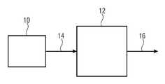
도 1은 자기장 센서의 일 예의 개략도를 도시한다.
도 2는 고-분해능 모드 또는 저-분해능 모드 중 어느 하나의 모드에서 동작하도록 설계된 자기장 센서의 일 예의 개략도를 도시한다.
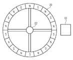
도 3은 자기장 센서 및 극 휠의 배열을 개략적으로 도시한다.
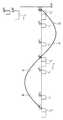
도 4는 저-분해능 모드를 설명하기 위한 개략도를 도시한다.
도 5는 고-분해능 모드를 설명하기 위한 개략도를 도시한다.
도 6 내지 도 9는, 본 개시내용에 따라 발진 신호들로부터 출력 신호들이 생성될 수 있는 방법의 예들을 설명하기 위한 신호 다이어그램들을 도시한다.
도 10은 본 개시내용에 따라 자기장 센서의 출력 신호를 생성하기 위한 방법의 일 예의 개략도를 도시한다.Examples of the present disclosure are described below with reference to the accompanying drawings.
1 shows a schematic diagram of an example of a magnetic field sensor.
2 shows a schematic diagram of an example of a magnetic field sensor designed to operate in either a high-resolution mode or a low-resolution mode.
3 schematically shows the arrangement of the magnetic field sensor and the pole wheel.
4 shows a schematic diagram for describing a low-resolution mode.
5 shows a schematic diagram for describing a high-resolution mode.
6-9 show signal diagrams for illustrating examples of how output signals can be generated from oscillation signals in accordance with the present disclosure.
10 shows a schematic diagram of an example of a method for generating an output signal of a magnetic field sensor according to the present disclosure.
이후, 본 개시내용의 예들은 첨부된 설명들을 사용하여 상세히 설명된다. 동일한 엘리먼트들 또는 동일한 기능성을 가진 엘리먼트들에 동일하거나 유사한 참조 부호들이 제공될 수 있고, 동일하거나 유사한 참조 부호들이 제공된 엘리먼트들의 반복된 설명이 통상적으로 생략되는 것이 지적되어야 한다. 동일하거나 유사한 참조 부호들을 가진 엘리먼트들의 설명들은 상호 교환가능하다. 뒤따르는 설명에서, 본 개시내용의 예들의 더 철저한 설명을 수득하기 위해 많은 세부사항이 설명된다. 그러나, 다른 예들이 이들 특정 세부사항들 없이 구현될 수 있다는 것은 통상의 기술자들에게 명백하다. 설명된 다양한 예들의 특징들은, 대응하는 조합의 특징들이 상호 배타적이거나 그런 조합이 명시적으로 배제되지 않으면, 서로 조합될 수 있다.Hereinafter, examples of the present disclosure are described in detail using the accompanying descriptions. It should be pointed out that identical or similar reference numerals may be provided to the same elements or elements having the same functionality, and repeated descriptions of elements provided with the same or similar reference numerals are usually omitted. Descriptions of elements having the same or similar reference signs are interchangeable. In the description that follows, many details are set forth to obtain a more thorough description of the examples of this disclosure. However, it is apparent to those skilled in the art that other examples may be implemented without these specific details. The features of the various examples described may be combined with each other unless the features of the corresponding combinations are mutually exclusive or such combination is not explicitly excluded.
도 1은 센서 유닛(10) 및 프로세싱 회로(12)를 포함하는 자기장 센서를 개략적으로 도시한다. 센서 유닛(10)은 가변 자기장에 기반하여 발진 신호(14)를 생성하도록 설계된다. 프로세싱 회로(12)는 발진 신호(14)를 수신하고, 이에 기반하여 출력 신호(16)를 생성하도록 설계된다.1 schematically shows a magnetic field sensor comprising a
예들에서, 센서 유닛(10)은 도 3에 개략적으로 예시된 바와 같이, 극 휠(20)의 회전에 기반하여 발진 신호를 생성하도록 설계될 수 있다. 극 휠(20)은 샤프트(22) 상에 회전가능하게 장착될 수 있다. 극 휠은 하나 또는 도 3에 개략적으로 도시된 바와 같이, 자기 북극들 및 자기 남극들의 복수의 극 쌍을 가질 수 있다. 센서 유닛(10)은, 극 휠(20)의 회전으로 인해 가변하는 자기장에 기반하여, 상기 센서 유닛이 평균 값 주위에서 변동하는 발진 신호를 생성하는 방식으로 극 휠(20)에 관하여 위치결정된다. 따라서, 예들에서, 발진 신호의 주파수는 회전 주파수, 예컨대 샤프트(22)와 함께 회전하는 휠의 회전 주파수에 의존할 수 있다.In examples, the
예들에서, 발진 신호는 사인파일 수 있다. 다른 예들에서, 발진 신호는 상이한 발진 형상, 예컨대 삼각형 또는 톱니-형상을 가질 수 있다.In examples, the oscillation signal may be sinusoidal. In other examples, the oscillation signal can have a different oscillation shape, such as triangular or serrated-shape.
예들에서, 센서 유닛은 가변 자기장에 기반하여 0° 내지 360°에서 변동하는 각도를 나타내는 발진 신호를 생성하도록 설계된다. 상기 발진 신호의 평균 값 교차들은 0° 내지 180°의 각도들에 대응할 수 있다. 예들에서, 센서 유닛은 가변 자기장에 기반하여, 서로에 관하여 90°만큼 위상-시프트된 2 개의 신호들을 생성하고, atan 함수 또는 CORDIC 알고리즘을 사용하여 이들 신호들로부터 각도 계산을 수행하도록 설계될 수 있다. 그런 예들에서, 발진 신호의 평균 값에 도달하고 발진 신호에서 평균 값과 상이한 한계 값들에 도달하는 것은 각각의 경우 대응하는 각도들에 도달하는 것을 나타낸다. 예들에서, 발진 신호의 평균 값 교차들은 0° 내지 180°의 각도들에 대응한다. 평균 값과 상이한 한계 값들은 예컨대 90° 내지 270°의 각도에 대응할 수 있다.In examples, the sensor unit is designed to generate an oscillating signal representing an angle varying from 0 ° to 360 ° based on a variable magnetic field. The average value crossings of the oscillation signal may correspond to angles of 0 ° to 180 °. In examples, the sensor unit may be designed to generate two signals phase-shifted by 90 ° relative to each other based on a variable magnetic field, and to perform angle calculations from these signals using an atan function or CORDIC algorithm. . In such examples, reaching the average value of the oscillation signal and reaching threshold values that are different from the average value in the oscillation signal indicates in each case reaching the corresponding angles. In examples, the average value intersections of the oscillation signal correspond to angles between 0 ° and 180 °. The limit values different from the average value can correspond to an angle of, for example, 90 ° to 270 °.
도 4는 시간에 따른 사인파 발진 신호(14)의 예시를 도시하고, 상기 신호의 진폭은 dB 단위로 예시된다. 발진 신호의 하나의 주기만이 도 4에 예시되고, 이는 주기적인 발진 신호인 것이 통상의 기술자들에게 명백하다.4 shows an example of a sine
도 4의 발진 신호의 평균 값은 0이고, 도시된 발진 신호는 t0, t1 및 t2에서 3 개의 제로 교차들을 가진다. 예로써, t0, t1 및 t2에서 제로 교차들은 0°, 180° 및 360°의 각도들에 대응할 수 있다. 도 4에 도시된 바와 같이, 각각의 경우 평균 값 교차 펄스(PM)는, 발진 신호가 도시된 예에서 평균 값(0)에 도달할 때 생성된다. 도 4에 도시된 바와 같이, 미리결정된 시간 지속기간(tpre)은 평균 값 교차 펄스의 생성과 평균 값 교차 사이에서 경과할 수 있다. 도 4에 추가로 도시된 바와 같이, 펄스들(PM)은 펄스 폭(w1)으로 생성된다.The average value of the oscillation signal in FIG. 4 is 0, and the illustrated oscillation signal has three zero crossings at t0 , t1 and t2 . For example, zero intersections at t0 , t1 and t2 can correspond to angles of 0 °, 180 ° and 360 °. As shown in Fig. 4, in each case, the average value crossing pulse PM is generated when the oscillation signal reaches the average value 0 in the illustrated example. As shown in FIG. 4, the predetermined time duration tpre may elapse between the generation of the average value crossing pulse and the crossing of the average value. 4, the pulses PM are generated with a pulse width w1.
도 4에 도시된 바와 같이 펄스(PM)를 가진 출력 신호는 저-분해능 모드에서의 발진 신호(14)에 기반하여 생성된 바와 같은 출력 신호를 나타낸다. 본 개시내용의 예들에서, 프로세싱 회로(12)는, 저-분해능 모드와 상이한 고-분해능 모드에서, 발진 신호가 평균 값에 도달할 때 각각의 경우 출력 신호에서 평균 값 교차 펄스(PM)를 생성하고, 발진 신호가 평균 값과 상이한 적어도 하나의 한계 값에 도달할 때 각각의 경우 출력 신호에서 한계 값 교차 펄스를 생성하도록 설계된다. 더 높은 분해능의 센서 출력 신호는 일반적으로 유리한 데, 그 이유는 그 센서 출력 신호가 더 높은 정확도로 센서에 의해 측정된 신호를 나타내거나 부가적인 정보, 이를테면 예컨대, 지터(jitter) 값들을 도출하는 것을 가능하게 할 수 있기 때문이다.The output signal with pulse PM as shown in FIG. 4 represents the output signal as generated based on the
도 5는 평균 값(24) 주위에서 변동하는 발진 신호(14)를 개략적으로 도시하고, 발진 신호(14)의 상한 값(26) 및 하한 값(28)이 추가로 예시된다. 발진 신호(14)는 시점들(t0, t1 및 t2)에서 평균 값(24)에 도달한다. 발진 신호(14)는 시점들(t3 및 t4)에서 상한 값(26)에 도달한다. 발진 신호는 시점들(t5 및 t6)에서 하한 값(28)에 도달한다. 예들에서, 프로세싱 회로는, 발진 신호(14)가 시점들(t3 및 t4)에서 상한 값(26)에 도달할 때, 그리고 발진 신호(14)가 시점들(t5 및 t6)에서 하한 값(28)에 도달할 때 각각의 경우 출력 신호(16)에서 한계 값 교차 펄스를 생성하도록 설계된다(도 5에 도시되지 않음).5 schematically shows the
이 시점에서 발진 신호가 한계 값에 도달할 때 펄스가 생성되는 공식은, 한계 값의 도달이 펄스 생성의 원인인 것을 의미하도록 의도된다는 것이 지적되어야 하고, 도달된 한계 값과 생성된 펄스 사이의 시간 지속기간이 있을 수 있고; 예컨대 지연(tpre)이 도면들에 예시된다.At this point it should be pointed out that the formula in which the pulse is generated when the oscillation signal reaches the limit value is intended to mean that the arrival of the limit value is the cause of the pulse generation, and the time between the reached limit value and the generated pulse. There may be a duration; For example, the delay tpre is illustrated in the figures.
도 6은, 프로세싱 회로가 고-분해능 모드에서 동작 중일 때 출력 신호(16)의 일 예를 도시한다. 도 3과 연관하여 이미 설명된 바와 같이, 평균 값 교차 펄스(PM)는, 발진 신호(14)가 평균 값에 도달할 때 출력 신호(16)에서 생성된다. 게다가, 개별 한계 값 교차 펄스들(PG)은, 발진 신호(14)가 평균 값과 상이한 한계 값들(30)에 도달할 때 출력 신호(16)에서 생성되고, 상기 한계 값들은 도 6에서 실선 원들에 의해 나타내진다. 이 시점에서 도 6의 한계 값들(30)이 순전히 개략적이고, 다른 한계 값들(32)이 실제 구현들에 사용될 수 있다는 것이 주목 되어야 하고, 다른 한계 값들의 예들은 도 6에서 파선 원들(32)에 의해 나타내진다. 도 6에 도시된 한계 값들은 순수하게 개략적인 것으로 간주되어야 하고, 출력 신호(16)에서 한계 값들 및 펄스 폭들은 어떠한 펄스들의 오버랩들도 발생하지 않도록 서로 조정되어야 한다.6 shows an example of the
도시된 예들에서, 평균 값 교차 펄스들(PM)의 펄스 폭은 w1이고 한계 값 교차 펄스들(PG)의 펄스 폭은 w2이다. 따라서, 프로세싱 회로는 평균 값 교차 펄스들(PM)의 펄스 폭과 상이한 펄스 폭을 가진 한계 값 교차 펄스들(PG)을 생성하도록 설계된다. 따라서, 그런 예들에서, 한계 값 교차 펄스들의 펄스 폭은, 평균 값 교차 펄스들의 펄스 폭과 상이한 한계 값 교차 펄스들의 펄스 폭으로 인해, 자기장 센서가 고-분해능 모드에서 동작 중인 것을 나타내도록 설정된다. 예로써, 출력 신호(16)를 수신하는 수신기는, 출력 신호(16)가 상이한 폭들의 펄스들을 가진다는 사실에 기반하여, 자기장 센서가 고-분해능 모드에서 동작 중인 것을 인식할 수 있다.In the illustrated examples, the pulse width of the average value crossing pulses PM is w1 and the pulse width of the limit value crossing pulses PG is w2. Thus, the processing circuit is designed to generate limit value crossing pulses PG having a pulse width different from the pulse width of the mean value crossing pulses PM. Thus, in such examples, the pulse width of the threshold crossing pulses is set to indicate that the magnetic field sensor is operating in a high-resolution mode, due to the pulse width of the threshold crossing pulses different from the average width pulses. By way of example, a receiver receiving the
예들에서, 프로세싱 회로는 차량의 휠의 회전 주파수에 의존하여, 고-분해능 모드에서만 동작하도록 설계될 수 있다. 그런 예들에서, 프로세싱 회로는 0 내지 300 km/h의 차량 속도 범위에 대응할 수 있는 회전 주파수의 전체 측정 범위에 걸쳐 고-분해능 모드에서 동작하도록 설계될 수 있다.In examples, the processing circuit can be designed to operate only in a high-resolution mode, depending on the rotational frequency of the vehicle's wheel. In such examples, the processing circuit can be designed to operate in a high-resolution mode over the entire measurement range of rotational frequency, which may correspond to a vehicle speed range of 0 to 300 km / h.
예들에서, 프로세싱 회로는 고-분해능 모드 또는 저-분해능 모드 중 어느 하나의 모드에서 동작하도록 설계될 수 있고, 저-분해능 모드에서, 프로세싱 회로는 출력 신호에서 평균 값 교차 펄스들만을 생성하도록 설계된다.In examples, the processing circuit can be designed to operate in either a high-resolution mode or a low-resolution mode, and in the low-resolution mode, the processing circuit is designed to generate only average value crossing pulses in the output signal. .
도 2는 센서 유닛(10) 및 프로세싱 회로(12)를 포함하는 대응하는 자기장 센서의 하나의 예시적인 실시예를 도시한다. 프로세싱 회로(12)는 도 2의 대응하는 블록들 및 스위치(38)에 의해 나타낸 바와 같이 저-분해능 모드(40)와 고-분해능 모드(42) 사이에서 스위칭가능하다. 프로세싱 회로(12)가 저-분해능 모드(40)인지 고-분해능 모드(42)인지에 의존하여, 출력 신호(16)는 평균 값 교차 펄스들(PM)(저-분해능 모드) 또는 평균 값 교차 펄스들(PM) 및 한계 값 교차 펄스들(PG)(고-분해능 펄스들)만을 가진다.2 shows one exemplary embodiment of a corresponding magnetic field sensor comprising a
예들에서, 자기장 센서는, 발진 신호의 주파수가 한계 주파수에 도달할 때 저-분해능 모드(40)와 고-분해능 모드(42) 사이에서 스위칭하도록 설계될 수 있다. 이어서, 상기 한계 주파수 초과에서, 평균 값 교차 펄스들만이 출력 신호(16)에서 생성되고, 이어서, 상기 주파수 미만에서, 평균 값 교차 펄스들 및 한계 값 교차 펄스들이 출력 신호(16)에서 생성된다. 예들에서, 상기 한계 주파수는 예컨대 30 km/h의 차량 속도에 대응하는 휠의 회전 주파수에 대응할 수 있다. 따라서, 예들에서, 고-분해능 모드는 느리게 이동할 때, 이를테면 예컨대 차량이 주차 중일 때 사용된다. 따라서, 더 느린 속도로 인해 또는 엔진 정지로 인해 자기장 센서의 출력 신호에 기반하여 올바르지 않은 값들이 결정될 위험성이 감소될 수 있다.In examples, the magnetic field sensor may be designed to switch between low-
본 개시내용의 예들에서, 프로세싱 회로는 출력 신호에서의 모든 펄스들을 동일한 레벨로 생성하도록 설계된다. 결과적으로, 출력 신호는 예컨대 AK 프로토콜을 사용하여 생성된 신호들과 분명하게 상이하다.In the examples of the present disclosure, the processing circuit is designed to generate all pulses in the output signal to the same level. Consequently, the output signal is clearly different from signals generated using, for example, the AK protocol.
일반적으로, 달성될 수 있는 분해능은 정의된 펄스 폭들에 의해서만 제한된다. 따라서, 예들에서, 한계 값 교차 펄스들이 생성된 부가적인 한계 값들의 수에 의존하여 3-배, 6-배 또는 12-배 더 높은 분해능을 달성하는 것이 가능하다.In general, the resolution that can be achieved is limited only by the defined pulse widths. Thus, in examples, it is possible to achieve a 3-fold, 6-fold, or 12-fold higher resolution depending on the number of additional threshold values for which threshold crossing pulses are generated.
도 7은 발진 신호(14) 및 이에 기반하여 생성된 출력 신호(16)의 개략도를 도시한다. 도 7에 도시된 예에서, 한계 값 교차 펄스들(PG)은 2 개의 부가적인 한계 값들, 즉 상한 값(26) 및 하한 값(28)에 대해 생성된다. 따라서, 3-배 더 높은 분해능이 달성될 수 있다. 이 예에서, 한계 값 교차 펄스들(PG)은 일단 다시 펄스 폭(w1)을 가진 평균 값 교차 펄스들(PM)보다 더 작은 폭(w2)을 가진다. 이 경우, 펄스 폭(w1)은 DR-R 또는 DR-L 펄스들의 표준 길이들에 대응할 수 있다. 이 경우 DR-R 펄스들은 우측을 향한 회전 방향의 경우 대응하는 평균 값 교차들 또는 제로 교차들의 경우에서의 표준 PWM 프로토콜에 따라 생성된 펄스들에 대응하고, 이 경우 DR-L 펄스들은 좌측을 향한 회전 방향의 경우 표준 PWM 프로토콜에 따라 생성된 펄스들에 대응한다. 따라서, 회전 방향에 의존하여, 평균 값 교차 펄스들은 상이한 펄스 폭들을 가질 수 있다. 한계 값 교차 펄스들(PG)은 상기 펄스 폭들과 상이한 펄스 폭, 예컨대 더 작은 펄스 폭(w2)을 가질 수 있다. 따라서, 수신기는, 자기장 센서가 고-분해능 모드에서 동작 중인 것을 상이한 펄스 폭들로부터 인식할 수 있다.7 shows a schematic diagram of the
예들에서, 프로세싱 회로는, 고-분해능 모드에서, 동일한 펄스 폭을 가진 평균 값 교차 펄스들 및 한계 값 교차 펄스들을 생성하도록 설계되고, 이 동일한 펄스 폭은 저-분해능 모드에서 평균 값 교차 펄스들의 펄스 폭과 상이하다. 도 8은, 평균 값 교차 펄스들(PM) 및 한계 값 교차 펄스들(PG)이 동일한 펄스 폭을 가진 대응하는 출력 신호(16)의 일 예를 도시한다. 이 펄스 폭은 저-분해능 모드에서 사용된 펄스 폭 또는 펄스 폭들과 상이하다. 저-분해능 모드에서, 출력 신호는, 저-분해능 모드만이 존재하는 종래의 표준 PWM 프로토콜에 따라 송신될 수 있다. 표준 PWM 프로토콜에 따라 사용된 바와 같은 대응하는 펄스들(PStandard)은 도 8의 파선들에 의해 예시된다. 그런 예들에서, 출력 신호를 수신하는 수신기는, 펄스들이 저-분해능 모드에서 발생하지 않는 펄스 폭을 가지기 때문에 자기장 센서가 고-분해능 모드에서 동작 중인 것을 인식할 수 있다. 예들에서, 평균 값 교차 펄스들 및 한계 값 교차 펄스들 둘 모두는 PWM 저-분해능 모드에서 DR-R 펄스들 및 DR-L 펄스들의 경우에 발생하지 않는 것과 같은 펄스 폭을 가진다. 따라서, 출력 신호의 수신기는, 자기장 센서가 고-분해능 모드에서 동작 중인지 저-분해능 모드에서 동작 중인지를 구별할 수 있다.In examples, the processing circuit is designed to generate, in high-resolution mode, average value crossing pulses with the same pulse width and threshold value crossing pulses, this same pulse width being a pulse of average value crossing pulses in low-resolution mode. It is different from the width. 8 shows an example of a
도 9는, 평균 값 교차 펄스들(PG) 및 한계 값 교차 펄스들(PM)이 상이한 펄스 폭들을 가지며 모든 펄스들이 저-분해능 모드에서 발생하는 각각의 펄스 폭과 상이한 펄스 폭을 가지는 출력 신호(16)의 일 예를 도시한다. 예로써, 도 9에서, 저-분해능 모드의 DR-L 펄스 및 DR-R 펄스는 파선들에 의해 예시되고, 이 펄스 폭은 고-분해능 모드에서 펄스들(PM)의 펄스 폭 및 펄스들(PG)의 펄스 폭과 상이하다. 따라서, 출력 신호(16)에서 발생하는 펄스들(PG, PM)의 상이한 펄스 폭들, 및 저-분해능 모드에서 발생하는 DR-L 펄스들 및 DR-R 펄스들의 펄스 폭들과 상이한 펄스 폭들 양자에 기반하여 고-분해능 모드 및 저-분해능 모드를 인식하는 것이 가능하다. 따라서, 출력 신호(16)를 수신하는 수신기, 예컨대 전자 제어 유닛(ECU)은, 펄스들이 지터 측정들에 사용될 수 있다는 것을 인식할 수 있다. 이것은, 종래의 표준 PWM 모드에 대응할 수 있는 고-분해능 모드와 저-분해능 모드 사이의 명확한 차이를 보장하고, 전자 제어 유닛, 펄스들 중 어느 것이 평균 값 교차 펄스들(PM)인지를 알게 할 수 있다.FIG. 9 shows an output in which the average value crossing pulses PG and the limit value crossing pulses PM have different pulse widths and all pulses have a pulse width different from each pulse width occurring in the low-resolution mode. An example of
예들에서, 자기장 센서는 자기장 센서에 대하여 이동하는 자석의 움직임을 검출하도록 설계될 수 있다. 프로세싱 회로는, 움직임이 제1 방향으로 발생하면 제1 펄스 폭을 가진 평균 값 교차 펄스들(PM)을 생성하고, 움직임이 제1 방향과 반대의 제2 방향으로 발생하면 제1 펄스 폭과 상이한 제2 펄스 폭을 가진 상기 평균 값 교차 펄스들을 생성하도록 설계될 수 있다. 예들에서, 제1 펄스 폭 및 제2 펄스 폭은 표준 DR-R 펄스들 및 표준 DR-L 펄스들의 펄스 폭들에 대응할 수 있다. 예들에서, 제1 및 제2 펄스 폭들은 그런 표준 펄스 폭들과 상이할 수 있다.In examples, the magnetic field sensor can be designed to detect the movement of a moving magnet relative to the magnetic field sensor. The processing circuit generates average value crossing pulses PM having a first pulse width when motion occurs in the first direction, and a first pulse width when motion occurs in a second direction opposite to the first direction. It can be designed to generate said average value crossing pulses with different second pulse widths. In examples, the first pulse width and the second pulse width may correspond to the pulse widths of standard DR-R pulses and standard DR-L pulses. In examples, the first and second pulse widths can be different from such standard pulse widths.
일반적으로, 표준 PWM 프로토콜에서, 추가 펄스 폭들은 정보를 나타내기 위해 존재할 수 있다. 예로써, 표준 PWM 프로토콜에서, 특정 펄스 폭은, 센서 유닛에 의해 생성된 신호의 신호 레벨이 임계 레벨보다 더 낮은 것을 나타내기 위해 사용되고, 그런 펄스들은, 설치 포지션이 중요하다는 사실에 관한 정보를 수득하는 소위 EL 펄스들로 알려진다. 그런 정보가 더 이상 요구되지 않으면, 예들에서, 그런 펄스들의 펄스 폭은, 자기장 센서가 고-분해능 모드에서 동작 중인 것을 나타내기 위해 사용될 수 있다.Generally, in standard PWM protocols, additional pulse widths may be present to indicate information. By way of example, in the standard PWM protocol, a specific pulse width is used to indicate that the signal level of the signal generated by the sensor unit is lower than the threshold level, and such pulses obtain information regarding the fact that the installation position is important. The so-called EL pulses are known. If such information is no longer required, in examples, the pulse width of such pulses can be used to indicate that the magnetic field sensor is operating in a high-resolution mode.
예들에서, 표준 PWM 프로토콜에 사용된 바와 같은 펄스 폭들은 모든 또는 한계 값 교차 펄스들에 대해서만 예컨대 0.5 배만큼 적응될 수 있다. 예들에서, 부가적인 펄스 폭들은 부가적인 한계 값 교차 펄스들(PG)을 나타내거나 또는 심지어 한계 값 교차 펄스들(PG)의 번호를 연속적으로 붙이는 데 사용될 수 있다. 한계 값 교차 펄스들(PG)이 고-분해능 모드에서만 생성되기 때문에, 한계 값 교차 펄스들(PG)은 또한 고-분해능 펄스들이라 지칭될 수 있다. 예들에서, 고-분해능 모드에서, 프로세싱 회로는, 발진 신호(16)가 평균 값과 상이한 제1 한계 값에 도달할 때 각각의 경우 출력 신호(16)에서 제1 한계 값 교차 펄스(PG)를 생성하고, 발진 신호(14)가 평균 값 및 제1 한계 값과 상이한 제2 한계 값에 도달할 때 출력 신호(16)에서 제2 한계 값 교차 펄스를 생성하도록 설계되고, 제1 한계 값 교차 펄스 및 제2 한계 값 교차 펄스는 상이한 펄스 폭들을 가진다.In examples, pulse widths as used in the standard PWM protocol can be adapted, eg, 0.5 times, for all or limit value crossing pulses only. In examples, additional pulse widths may be used to indicate additional threshold crossing pulses PG , or even to number consecutive threshold crossing pulses PG. Since the threshold crossing pulses PG are generated only in the high-resolution mode, the threshold crossing pulses PG may also be referred to as high-resolution pulses. In the examples, and - at the resolution mode, the processing circuit is the oscillating signal (16), the first threshold crossing pulse in each case the output signals 16 to reach the average value and the value different from the first threshold (PG) Is designed to generate a second threshold crossing pulse in the
고-분해능 펄스들은 표준 PWM 프로토콜들에 사용된 펄스 폭들 사이에 놓이는 펄스 폭들로 생성될 수 있다. 예로써, 표준 DR-L 펄스들에 대한 펄스 폭들은 76 내지 104 μs 범위, 통상적으로 90 μs이고, 표준 DR-R 펄스들의 펄스 폭은 154 내지 207 μs 범위, 통상적으로 180 μs이다. EL 펄스를 포함하는 표준 DR-L 펄스의 펄스 폭은 306 내지 414 μs, 통상적으로 360 μs이고, EL 펄스를 포함하는 표준 DR-R 펄스의 펄스 폭은 616 내지 828 μs, 통상적으로 720 μs이다. PDM 프로토콜의 고-분해능 펄스들에 대한 펄스 폭들은 충분한 간격으로 이들 펄스 폭들 사이에 있고, 고-분해능 펄스들의 펄스 폭과 표준 PWM 펄스들 사이의 간격은 각각의 경우 예컨대, 45 μs일 수 있다.High-resolution pulses can be generated with pulse widths that lie between the pulse widths used in standard PWM protocols. By way of example, pulse widths for standard DR-L pulses range from 76 to 104 μs, typically 90 μs, and pulse widths for standard DR-R pulses range from 154 to 207 μs, typically 180 μs. The pulse width of standard DR-L pulses containing EL pulses is 306 to 414 μs, typically 360 μs, and the pulse width of standard DR-R pulses containing EL pulses is 616 to 828 μs, typically 720 μs. The pulse widths for the high-resolution pulses of the PDM protocol are between these pulse widths at sufficient intervals, and the interval between the pulse widths of the high-resolution pulses and standard PWM pulses can be, for example, 45 μs in each case.
도 10은 본 개시내용에 따른 방법의 일 예의 흐름도를 개략적으로 도시한다. 100에서, 평균 값 주위에서 변동하는 발진 신호는 가변 자기장에 기반하여 생성된다. 102에서, 출력 신호는 발진 신호에 기반하여 생성된다. 여기서, 저-분해능 모드와 상이한 고-분해능 모드에서, 각각의 경우 평균 값 교차 펄스는, 발진 신호가 평균 값에 도달할 때 출력 신호에서 생성된다. 발진 신호가 평균 값과 상이한 적어도 하나의 한계 값에 도달할 때, 각각의 경우 한계 값 교차 펄스는 출력 신호에서 생성된다. 적어도 평균 값 교차 펄스 또는 한계 값 교차 펄스 중 어느 하나의 펄스의 펄스 폭은, 방법이 고-분해능 모드에서 동작 중인 것을 나타내도록 설정된다.10 schematically shows a flow chart of an example of a method according to the present disclosure. At 100, an oscillating signal that fluctuates around the average value is generated based on a variable magnetic field. At 102, an output signal is generated based on the oscillation signal. Here, in the high-resolution mode different from the low-resolution mode, the average value cross pulse in each case is generated in the output signal when the oscillation signal reaches the average value. When the oscillation signal reaches at least one threshold value different from the average value, in each case a threshold crossing pulse is generated in the output signal. The pulse width of at least either the average value crossing pulse or the threshold value crossing pulse is set to indicate that the method is operating in a high-resolution mode.
따라서, 본 개시내용의 예들은 PWM 프로토콜을 사용하여 고-분해능 출력 신호를 생성 및 송신하는 것을 가능하게 한다. 출력 신호가 고-분해능 출력 신호이다, 즉 자기장 센서가 고-분해능 모드에서 동작 중이라는 사실은 출력 신호의 펄스들의 펄스 폭에 의해 나타내진다. 이것은, 수신기 회로들, 예컨대 자동차들의 전자 제어 유닛들이, 자기장 센서가 고-분해능 모드에서 동작 중인 것을 인식할 수 있게 한다. 이것은 수신기 회로들이 출력 신호를 정확하게 해석 및 평가할 수 있게 한다. 센서가 고-분해능 모드에서 동작 중 인지에 대한 정보가 펄스 폭에 의해 인코딩되기 때문에, 상이한 펄스 높이들을 가진 펄스들을 송신하는 것이 필요하지 않다. 게다가, 대응하는 정보를 포함하는 디지털 데이터를 송신하는 것이 필요하지 않다. 각각의 경우 각각 평균 값 또는 한계 값을 통해 각각 교차할 때 하나의 펄스만이 송신되어야 하기 때문에, 고-분해능 모드는 낮은 회전 주파수들로 제한되는 것이 아니라, 오히려 전체 측정 범위에 걸쳐, 예컨대 전체 차량 속도 범위에 걸쳐 구현될 수 있다.Thus, examples of the present disclosure make it possible to generate and transmit a high-resolution output signal using the PWM protocol. The output signal is a high-resolution output signal, that is, the fact that the magnetic field sensor is operating in a high-resolution mode is indicated by the pulse width of the pulses of the output signal. This allows receiver circuits, such as electronic control units of automobiles, to recognize that the magnetic field sensor is operating in a high-resolution mode. This allows receiver circuits to accurately interpret and evaluate the output signal. Since information about whether the sensor is operating in high-resolution mode is encoded by the pulse width, it is not necessary to transmit pulses with different pulse heights. Moreover, it is not necessary to transmit digital data containing corresponding information. The high-resolution mode is not limited to low rotational frequencies, because in each case only one pulse must be transmitted when each crosses through an average value or a limit value, but rather across the entire measurement range, eg the entire vehicle It can be implemented over a range of speeds.
본 개시내용의 예들은 고-분해능 모드를 부가적으로 도입함으로써 저-분해능 모드만을 가진 표준 PWM 프로토콜들을 확장하는 것을 가능하게 한다.Examples of the present disclosure make it possible to extend standard PWM protocols with only a low-resolution mode by additionally introducing a high-resolution mode.
본 개시내용의 예들은 본원에 개시된 바와 같은 자기장 센서를 포함하고 휠 속도를 나타내는 출력 신호를 출력하는 휠 속도 센서들에 관한 것이다. 예들에서, 자기장 센서의 출력 신호는 자율 주행 애플리케이션들, 예컨대 자율 주차 애플리케이션들에 사용될 수 있다.Examples of the present disclosure relate to wheel speed sensors that include a magnetic field sensor as disclosed herein and output an output signal indicative of wheel speed. In examples, the output signal of the magnetic field sensor may be used in autonomous driving applications, such as autonomous parking applications.
예들에서, 프로세싱 회로는 임의의 적합한 회로 구조들, 예컨대 마이크로프로세서 회로들, ASIC 회로들, CMOS 회로들 등에 의해 구현될 수 있다. 예들에서, 프로세싱 회로는 하드웨어 구조들 및 기계-판독가능 명령들의 조합으로 구현될 수 있다. 예로써, 프로세싱 회로는 프로세서 및 본원에 설명된 방법들이 프로세서에 의해 실행될 때 수행되게 초래하는 기계-판독가능 명령들을 저장하는 저장 디바이스들을 포함할 수 있다.In examples, the processing circuit can be implemented by any suitable circuit structures, such as microprocessor circuits, ASIC circuits, CMOS circuits, and the like. In examples, processing circuitry may be implemented with a combination of hardware structures and machine-readable instructions. By way of example, the processing circuit can include a processor and storage devices that store machine-readable instructions that cause the methods described herein to be performed when executed by the processor.
비록 본 개시내용의 일부 양상들이 디바이스와 연관된 특징들로 설명되었지만, 그런 설명이 마찬가지로 대응하는 방법 특징들의 설명으로 간주될 수 있다는 것이 명백하다. 비록 일부 양상들이 방법과 연관된 특징들로 설명되었지만, 그런 설명이 또한 디바이스 또는 디바이스의 기능성의 대응하는 특징들의 설명으로 간주될 수 있다는 것이 명백하다.Although some aspects of the present disclosure have been described with features associated with the device, it is apparent that such description can likewise be regarded as a description of corresponding method features. Although some aspects have been described with features associated with a method, it is clear that such description can also be considered a description of corresponding features of a device or device functionality.
위의 상세한 설명에서, 일부 사례들에서 상이한 특징들은 본 개시내용을 합리화하기 위해 예들에서 함께 그룹화되었다. 이런 타입의 본 개시내용은, 청구된 예들이 각각의 청구항에 명시적으로 나타낸 것보다 더 많은 특징들을 가진다는 의도로서 해석되지 않아야 한다. 오히려, 아래 청구항들에 의해 나타내진 바와 같이, 청구 대상은 개시된 개별 예의 모든 특징들보다 더 적게 존재한다. 결과적으로, 아래의 청구항들은 이로써 상세한 설명에 통합되고, 각각의 청구항은 별도의 전용 예를 대표할 수 있다. 각각의 청구항이 별도의 전용 예를 대표할 수 있는 반면, 종속항들이 청구항들에서 하나 이상의 다른 청구항과 특정 조합을 다시 참조하지만, 다른 예들이 또한 임의의 다른 종속항의 청구 대상과 종속항들의 조합 또는 다른 종속항 또는 독립항들과 각각의 특징의 조합을 포함하는 것이 주목되어야 한다. 그런 조합들은, 특정 조합이 의도되지 않았다는 설명이 주어지지 않으면, 포함될 것이다. 게다가, 이 청구항이 독립항을 직접 인용하지 않더라도, 임의의 다른 독립항과 청구항의 특징들의 조합이 또한 포함되는 것이 의도된다.In the detailed description above, different features in some instances are grouped together in examples to rationalize the present disclosure. This type of disclosure should not be construed with the intention that the claimed examples have more features than are expressly indicated in each claim. Rather, as indicated by the claims below, the claimed subject matter is less than all the features of the individual examples disclosed. Consequently, the claims below are hereby incorporated into the detailed description, with each claim being able to represent a separate dedicated example. While each claim may represent a separate, dedicated example, the dependent claims refer back to one or more other claims and specific combinations in the claims, but other examples also refer to the subject matter of any other dependent claim and the combination of dependent claims or It should be noted that it includes other dependent or independent claims and a combination of each feature. Such combinations will be included unless given a description that the particular combination was not intended. Moreover, even if this claim does not directly refer to the independent claim, it is intended that any other combination of the independent claim and the features of the claim is also included.
양상 1에 따라, 자기장 센서는 다음 특징들을 가지며: 가변 자기장에 기반하여 평균 값 주위에서 변동하는 발진 신호를 생성하도록 설계된 센서 유닛; 및 발진 신호에 기반하여 출력 신호를 생성하도록 설계된 프로세싱 회로를 포함하고, 저-분해능 모드와 상이한 고-분해능 모드에서, 프로세싱 회로는, 발진 신호가 평균 값에 도달할 때 각각의 경우 출력 신호에서 평균 값 교차 펄스를 생성하고, 발진 신호가 평균 값과 상이한 적어도 하나의 한계 값에 도달할 때 각각의 경우 출력 신호에서 한계 값 교차 펄스를 생성하도록 설계되고, 적어도 평균 값 교차 펄스 또는 한계 값 교차 펄스 중 어느 하나의 펄스의 펄스 폭은, 자기장 센서가 고-분해능 모드에서 동작 중인 것을 나타내도록 설정된다.According to aspect 1, a magnetic field sensor has the following characteristics: a sensor unit designed to generate an oscillating signal that fluctuates around an average value based on a variable magnetic field; And a processing circuit designed to generate an output signal based on the oscillation signal, and in a high-resolution mode different from the low-resolution mode, the processing circuit is averaged in the output signal in each case when the oscillation signal reaches the average value. Designed to generate a value cross pulse, and in each case an output signal to generate a limit value cross pulse when the oscillation signal reaches at least one threshold value different from the average value, at least either the average value cross pulse or the limit value cross pulse The pulse width of either pulse is set to indicate that the magnetic field sensor is operating in a high-resolution mode.
양상 2에 따라, 양상 1에 따른 자기장 센서의 경우, 발진 신호는 0° 내지 360°에서 변동하는 각도를 나타내고, 발진 신호의 연속적인 평균 값 교차들은 0° 내지 180°의 각도들에 대응하고, 적어도 하나의 한계 값은 0° 내지 180°와 상이한 각도에 대응한다.According to aspect 2, in the case of the magnetic field sensor according to aspect 1, the oscillation signal represents an angle varying from 0 ° to 360 °, and the continuous average value intersections of the oscillation signal correspond to angles from 0 ° to 180 °, The at least one limit value corresponds to an angle different from 0 ° to 180 °.
양상 3에 따라, 양상 1 또는 양상 2에 따른 자기장 센서는 고-분해능 모드 또는 저-분해능 모드 중 어느 하나의 모드에서 동작하도록 설계되고, 저-분해능 모드에서, 프로세싱 회로는 출력 신호에서 평균 값 교차 펄스들만을 생성하도록 설계된다.According to aspect 3, the magnetic field sensor according to aspect 1 or aspect 2 is designed to operate in either the high-resolution mode or the low-resolution mode, and in the low-resolution mode, the processing circuit crosses the average value in the output signal It is designed to generate only pulses.
양상 4에 따라, 양상 1 내지 양상 3 중 어느 한 양상에 따른 자기장 센서에서, 프로세싱 회로는 평균 값 교차 펄스들의 펄스 폭과 상이한 펄스 폭을 가진 한계 값 교차 펄스들을 생성하도록 설계된다.According to aspect 4, in the magnetic field sensor according to any one of aspects 1 to 3, the processing circuit is designed to generate threshold value cross pulses having a pulse width different from the pulse width of the average value cross pulses.
양상 5에 따라, 양상 1 내지 양상 3 중 어느 한 양상에 따른 자기장 센서에서, 프로세싱 회로는, 고-분해능 모드에서, 동일한 펄스 폭을 가진 평균 값 교차 펄스들 및 한계 값 교차 펄스들을 생성하도록 설계되고, 이 동일한 펄스 폭은 저-분해능 모드에서 평균 값 교차 펄스들의 펄스 폭과 상이하다.According to aspect 5, in the magnetic field sensor according to any one of aspects 1 to 3, the processing circuit is designed to generate average value crossing pulses and threshold crossing pulses having the same pulse width, in a high-resolution mode , This same pulse width is different from the pulse width of the average value crossing pulses in the low-resolution mode.
양상 6에 따라, 양상 1 내지 양상 4 중 어느 한 양상에 따른 자기장 센서에서, 고-분해능 모드에서, 프로세싱 회로는, 발진 신호가 평균 값과 상이한 제1 한계 값에 도달할 때 각각의 경우 출력 신호에서 제1 한계 값 교차 펄스를 생성하고, 발진 신호가 평균 값 및 제1 한계 값과 상이한 제2 한계 값에 도달할 때 출력 신호에서 제2 한계 값 교차 펄스를 생성하도록 설계되고, 제1 한계 값 교차 펄스 및 제2 한계 값 교차 펄스는 상이한 펄스 폭들을 가진다.According to aspect 6, in the magnetic field sensor according to any one of aspects 1 to 4, in the high-resolution mode, the processing circuit, in each case output signal when the oscillation signal reaches a first threshold value different from the average value Is designed to generate a first threshold value cross pulse, and to generate a second threshold value cross pulse in the output signal when the oscillation signal reaches a second threshold value different from the average value and the first threshold value, the first threshold value The cross pulse and the second threshold value cross pulse have different pulse widths.
양상 7에 따라, 양상 1 내지 양상 6 중 어느 한 양상에 따른 자기장 센서에서, 프로세싱 회로는 저-분해능 모드에서 사용된 각각의 펄스 폭과 상이한 펄스 폭을 가진 한계 값 교차 펄스들을 생성하도록 설계된다.According to aspect 7, in the magnetic field sensor according to any one of aspects 1 to 6, the processing circuit is designed to generate threshold crossing pulses having a pulse width different from each pulse width used in the low-resolution mode.
양상 8에 따라, 양상 1 내지 양상 7 중 어느 한 양상에 따른 자기장 센서는 자기장 센서에 대하여 이동하는 자석의 움직임을 검출하도록 설계되고, 프로세싱 회로는, 움직임이 제1 방향으로 발생하면 제1 펄스 폭을 가진 평균 값 교차 펄스들을 생성하고, 움직임이 제1 방향과 반대의 제2 방향으로 발생하면 제1 펄스 폭과 상이한 제2 펄스 폭을 가진 상기 평균 값 교차 펄스들을 생성하도록 설계된다.According to aspect 8, the magnetic field sensor according to any one of aspects 1 to 7 is designed to detect the movement of the magnet moving relative to the magnetic field sensor, and the processing circuitry includes a first pulse width when the movement occurs in the first direction It is designed to generate average value crossing pulses with and if the motion occurs in a second direction opposite to the first direction, the average value crossing pulses having a second pulse width different from the first pulse width.
양상 9에 따라, 양상 1 내지 양상 8 중 어느 한 양상에 따른 자기장 센서에서, 프로세싱 회로는 출력 신호에서의 모든 펄스들을 동일한 레벨로 생성하도록 설계된다.According to aspect 9, in the magnetic field sensor according to any one of aspects 1 to 8, the processing circuit is designed to generate all pulses in the output signal to the same level.
양상 10에 따라, 양상 1 내지 양상 9 중 어느 한 양상에 따른 자기장 센서에서, 발진 신호의 주파수는 휠의 회전 주파수에 의존하고, 프로세싱 회로는 회전 주파수의 전체 측정 범위에 걸쳐 고-분해능 모드에서만 동작하도록 설계된다.According to
양상 11에 따라, 양상 1 내지 양상 9 중 어느 한 양상에 따른 자기장 센서에서, 발진 신호의 주파수는 휠의 회전 주파수에 의존하고, 프로세싱 회로는, 회전 주파수가 한계 주파수 미만일 때 고-분해능 모드에서 동작하고, 회전 주파수가 한계 주파수 초과일 때 저-분해능 모드에서 동작하도록 설계된다.According to aspect 11, in the magnetic field sensor according to any one of aspects 1 to 9, the frequency of the oscillation signal depends on the rotational frequency of the wheel, and the processing circuit operates in the high-resolution mode when the rotational frequency is less than the limiting frequency And is designed to operate in a low-resolution mode when the rotation frequency exceeds the limit frequency.
양상 12에 따라, 자기장 센서의 출력 신호를 생성하기 위한 방법은 다음 특징들을 가지며: 가변 자기장에 기반하여 평균 값 주위에서 변동하는 발진 신호를 생성하는 단계; 및 발진 신호에 기반하여 출력 신호를 생성하는 단계를 포함하고, 저-분해능 모드와 상이한 고-분해능 모드에서, 발진 신호가 평균 값에 도달할 때 각각의 경우 평균 값 교차 펄스가 출력 신호에서 생성되고, 발진 신호가 평균 값과 상이한 적어도 하나의 한계 값에 도달할 때 각각의 경우 한계 값 교차 펄스가 출력 신호에서 생성되고, 적어도 평균 값 교차 펄스 또는 한계 값 교차 펄스 중 어느 하나의 펄스의 펄스 폭은, 방법이 고-분해능 모드에서 동작 중인 것을 나타내도록 설정된다.According to
양상 13에 따라, 양상 12에 따른 방법에서, 발진 신호는 0° 내지 360°에서 변동하는 각도를 나타내고, 발진 신호의 연속적인 평균 값 교차들은 0° 내지 180°의 각도들에 대응하고, 적어도 하나의 한계 값은 0° 내지 180°와 상이한 각도에 대응한다.According to aspect 13, in the method according to
양상 14에 따라, 양상 12 또는 양상 13에 따른 방법은 고-분해능 모드와 저-분해능 모드 사이에서 스위칭하는 단계를 포함하고, 저-분해능 모드에서, 평균 값 교차 펄스들만이 출력 신호에서 생성된다.According to
양상 15에 따라, 양상 12 내지 양상 14 중 어느 한 양상에 따른 방법에서, 한계 값 교차 펄스들은 평균 값 교차 펄스들의 펄스 폭과 상이한 펄스 폭으로 생성된다.According to aspect 15, in the method according to any one of
양상 16에 따라, 양상 12 내지 양상 14 중 어느 한 양상에 따른 방법에서, 고-분해능 모드에서, 평균 값 교차 펄스들 및 한계 값 교차 펄스들은 동일한 펄스 폭으로 생성되고, 이 동일한 펄스 폭은 저-분해능 모드에서 평균 값 교차 펄스들의 펄스 폭과 상이하다.According to
양상 17에 따라, 양상 12 내지 양상 16 중 어느 한 양상에 따른 방법에서, 고-분해능 모드에서, 발진 신호가 평균 값과 상이한 제1 한계 값에 도달할 때 각각의 경우 제1 한계 값 교차 펄스가 출력 신호에서 생성되고, 발진 신호가 평균 값 및 제1 한계 값과 상이한 제2 한계 값에 도달할 때 제2 한계 값 교차 펄스가 출력 신호에서 생성되고, 제1 한계 값 교차 펄스 및 제2 한계 값 교차 펄스는 상이한 펄스 폭들을 가진다.According to aspect 17, in the method according to any one of
양상 18에 따라, 양상 12 내지 양상 17 중 어느 한 양상에 따른 방법에서, 한계 값 교차 펄스들은 저-분해능 모드에서 사용된 각각의 펄스 폭과 상이한 펄스 폭으로 생성된다.According to aspect 18, in the method according to any of
양상 19에 따라, 양상 12 내지 양상 18 중 어느 한 양상에 따른 방법에서, 발진 신호는 자기장 센서에 대하여 이동하는 자석의 움직임에 기반하고, 평균 값 교차 펄스들은, 움직임이 제1 방향으로 발생하면 제1 펄스 폭으로 생성되고, 움직임이 제1 방향과 반대의 제2 방향으로 발생하면 제1 펄스 폭과 상이한 제2 펄스 폭으로 생성된다.According to aspect 19, in the method according to any one of
양상 20에 따라, 양상 12 내지 양상 19 중 임의의 양상에 따른 방법에서, 출력 신호에서의 모든 펄스들은 동일한 레벨로 생성된다.According to
양상 21에 따라, 양상 12 내지 양상 19 중 어느 한 양상에 따른 방법에서, 발진 신호의 주파수는 휠의 회전 주파수에 의존하고, 방법은 회전 주파수의 전체 측정 범위에 걸쳐 고-분해능 모드에서만 동작한다.According to aspect 21, in the method according to any one of
양상 22에 따라, 양상 12 내지 양상 19 중 어느 한 양상에 따른 방법에서, 발진 신호의 주파수는 휠의 회전 주파수에 의존하고, 방법은, 회전 주파수가 한계 주파수 미만일 때 고-분해능 모드에서 동작하고, 회전 주파수가 한계 주파수 초과일 때 저-분해능 모드에서 동작한다.According to
위에서 설명된 예들은 본 개시내용의 원리들에 대한 단순 예시이다. 설명된 배열들 및 세부사항들의 수정들 및 변형들이 통상의 기술자들에게 명백한 것이 이해되어야 한다. 그러므로, 본 개시내용이 첨부된 특허 청구항들에 의해서만 제한되고 예들의 기술 및 설명의 목적을 위해 제시된 특정 세부사항들에 의해 제한되지 않는 것이 의도된다.The examples described above are simple examples of the principles of the present disclosure. It should be understood that modifications and variations of the described arrangements and details are apparent to those skilled in the art. Therefore, it is intended that the present disclosure is limited only by the appended patent claims and not by the specific details presented for purposes of description and description of the examples.
10센서 유닛
12프로세싱 회로
14발진 신호
16출력 신호
20극 휠
22샤프트
24평균 값
26상한 값
28하한 값
30한계 값들
32가능한 한계 값들
38스위치
40저-분해능 모드
42고-분해능 모드10 sensor units
12 processing circuit
14 oscillation signal
16 output signal
20 pole wheel
22 shaft
24 average value
26 upper limit
28 lower limit
30 limit values
32 possible limit values
38 switch
40 low-resolution modes
42 high-resolution modes
Claims (22)
Translated fromKorean가변 자기장에 기반하여 평균 값 주위에서 변동하는 발진 신호를 생성하도록 설계된 센서 유닛; 및
상기 발진 신호에 기반하여 출력 신호를 생성하도록 설계된 프로세싱 회로를 포함하고, 저-분해능 모드와 상이한 고-분해능 모드에서, 상기 프로세싱 회로는, 상기 발진 신호가 상기 평균 값에 도달할 때 각각의 경우 상기 출력 신호에서 평균 값 교차 펄스를 생성하고, 상기 발진 신호가 상기 평균 값과 상이한 적어도 하나의 한계 값에 도달할 때 각각의 경우 상기 출력 신호에서 한계 값 교차 펄스를 생성하도록 설계되고,
적어도 상기 평균 값 교차 펄스 또는 상기 한계 값 교차 펄스 중 어느 하나의 펄스의 펄스 폭은, 상기 자기장 센서가 상기 고-분해능 모드에서 동작 중인 것을 나타내도록 설정되는 것을 특징으로 하는, 자기장 센서.As a magnetic field sensor,
A sensor unit designed to generate an oscillating signal that fluctuates around an average value based on a variable magnetic field; And
And a processing circuit designed to generate an output signal based on the oscillation signal, and in a high-resolution mode different from a low-resolution mode, the processing circuit may, in each case when the oscillation signal reaches the average value, Is designed to generate an average value cross pulse in the output signal, and in each case generate an threshold value cross pulse in the output signal when the oscillation signal reaches at least one threshold value different from the average value,
The magnetic field sensor, characterized in that the pulse width of at least one of the average value crossing pulse or the threshold value crossing pulse is set to indicate that the magnetic field sensor is operating in the high-resolution mode.
가변 자기장에 기반하여 평균 값 주위에서 변동하는 발진 신호를 생성하는 단계; 및
상기 발진 신호에 기반하여 상기 출력 신호를 생성하는 단계를 포함하고, 저-분해능 모드와 상이한 고-분해능 모드에서, 상기 발진 신호가 상기 평균 값에 도달할 때 각각의 경우 평균 값 교차 펄스가 출력 신호에서 생성되고, 상기 발진 신호가 상기 평균 값과 상이한 적어도 하나의 한계 값에 도달할 때 각각의 경우 한계 값 교차 펄스가 상기 출력 신호에서 생성되고,
적어도 상기 평균 값 교차 펄스 또는 상기 한계 값 교차 펄스 중 어느 하나의 펄스의 펄스 폭은, 상기 방법이 상기 고-분해능 모드에서 동작 중인 것을 나타내도록 설정되는 것을 특징으로 하는, 방법.As a method for generating the output signal of the magnetic field sensor,
Generating an oscillating signal that fluctuates around an average value based on a variable magnetic field; And
Generating the output signal based on the oscillation signal, and in a high-resolution mode different from a low-resolution mode, an average value cross pulse in each case when the oscillation signal reaches the average value is an output signal And in each case a threshold value crossing pulse is generated in the output signal when the oscillation signal reaches at least one threshold value different from the average value,
The pulse width of at least one of the average value crossing pulse or the threshold value crossing pulse is set to indicate that the method is operating in the high-resolution mode.
Applications Claiming Priority (2)
| Application Number | Priority Date | Filing Date | Title |
|---|---|---|---|
| DE102018215938.6ADE102018215938B4 (en) | 2018-09-19 | 2018-09-19 | high-resolution mode for a magnetic field sensor |
| DE102018215938.6 | 2018-09-19 |
Publications (2)
| Publication Number | Publication Date |
|---|---|
| KR20200033747Atrue KR20200033747A (en) | 2020-03-30 |
| KR102294824B1 KR102294824B1 (en) | 2021-08-31 |
Family
ID=69647106
Family Applications (1)
| Application Number | Title | Priority Date | Filing Date |
|---|---|---|---|
| KR1020190114143AActiveKR102294824B1 (en) | 2018-09-19 | 2019-09-17 | High-resolution mode for a magnetic field sensor |
Country Status (4)
| Country | Link |
|---|---|
| US (2) | US11499846B2 (en) |
| KR (1) | KR102294824B1 (en) |
| CN (1) | CN110927399A (en) |
| DE (1) | DE102018215938B4 (en) |
Families Citing this family (3)
| Publication number | Priority date | Publication date | Assignee | Title |
|---|---|---|---|---|
| CN115023617A (en) | 2020-01-29 | 2022-09-06 | 大陆汽车科技有限公司 | High Resolution PWM Wheel Speed Sensor Protocol |
| DE102021212324B4 (en)* | 2021-11-02 | 2024-10-17 | Continental Automotive Technologies GmbH | Method for evaluating wheel sensor signals, arrangement therefor and braking system comprising the arrangement |
| US20250251257A1 (en)* | 2024-02-07 | 2025-08-07 | Allegro Microsystems, Llc | Dynamic resolution sensor |
Citations (6)
| Publication number | Priority date | Publication date | Assignee | Title |
|---|---|---|---|---|
| JP2000088867A (en)* | 1998-09-08 | 2000-03-31 | Hitachi Ltd | Signal detection circuit and rotation detection system |
| JP2007174674A (en)* | 2005-12-23 | 2007-07-05 | Robert Bosch Gmbh | Method of increasing information density on signal transmission line |
| KR20140140572A (en)* | 2012-03-06 | 2014-12-09 | 알레그로 마이크로시스템스, 엘엘씨 | Magnetic field sensor for sensing rotation of an object |
| US20140375312A1 (en)* | 2013-06-20 | 2014-12-25 | Allegro Microsystems, Llc | Systems and Methods for Providing Signal Encoding Representative of a Signature Region in a Target |
| US20170336225A1 (en)* | 2016-05-17 | 2017-11-23 | Allegro MicroSysterns, LLC | Magnetic Field Sensors And Output Signal Formats For A Magnetic Field Sensor |
| US20180210004A1 (en) | 2015-07-20 | 2018-07-26 | Robert Bosch Gmbh | Method and Device for Operating a Rotational Speed Sensor, Rotational Speed Sensor Device |
Family Cites Families (11)
| Publication number | Priority date | Publication date | Assignee | Title |
|---|---|---|---|---|
| JP2574873B2 (en)* | 1988-08-24 | 1997-01-22 | 株式会社日立製作所 | Position or speed detector |
| US6815944B2 (en)* | 2002-01-31 | 2004-11-09 | Allegro Microsystems, Inc. | Method and apparatus for providing information from a speed and direction sensor |
| JP4605435B2 (en)* | 2004-03-24 | 2011-01-05 | アイシン精機株式会社 | Rotation detector |
| KR20080041024A (en)* | 2006-11-06 | 2008-05-09 | 현대자동차주식회사 | Forward / Reverse Detection Method of CVT Vehicle |
| DE102014216295A1 (en)* | 2014-08-15 | 2016-02-18 | Continental Teves Ag & Co. Ohg | Resolution increase in the speed signal between speed pulses |
| JP2017044665A (en)* | 2015-08-28 | 2017-03-02 | アイシン精機株式会社 | Rotation sensor |
| US10495700B2 (en)* | 2016-01-29 | 2019-12-03 | Allegro Microsystems, Llc | Method and system for providing information about a target object in a formatted output signal |
| CN108122401B (en)* | 2016-11-29 | 2021-10-15 | 英飞凌科技股份有限公司 | Signal generator, decoder, method for generating a transmission signal, and method for determining velocity data |
| DE102016125183B4 (en)* | 2016-12-21 | 2022-01-27 | Infineon Technologies Ag | Devices for encoding and decoding wheel speed sensor signals and methods for communicating encoded wheel speed sensor signals |
| US10656170B2 (en)* | 2018-05-17 | 2020-05-19 | Allegro Microsystems, Llc | Magnetic field sensors and output signal formats for a magnetic field sensor |
| DE102018121998A1 (en)* | 2018-09-10 | 2020-03-12 | Infineon Technologies Ag | Devices and methods for transmitting and receiving speed information |
- 2018
- 2018-09-19DEDE102018215938.6Apatent/DE102018215938B4/enactiveActive
- 2019
- 2019-08-19CNCN201910764160.6Apatent/CN110927399A/enactivePending
- 2019-09-17USUS16/573,418patent/US11499846B2/enactiveActive
- 2019-09-17KRKR1020190114143Apatent/KR102294824B1/enactiveActive
- 2022
- 2022-10-13USUS18/046,226patent/US11971279B2/enactiveActive
Patent Citations (6)
| Publication number | Priority date | Publication date | Assignee | Title |
|---|---|---|---|---|
| JP2000088867A (en)* | 1998-09-08 | 2000-03-31 | Hitachi Ltd | Signal detection circuit and rotation detection system |
| JP2007174674A (en)* | 2005-12-23 | 2007-07-05 | Robert Bosch Gmbh | Method of increasing information density on signal transmission line |
| KR20140140572A (en)* | 2012-03-06 | 2014-12-09 | 알레그로 마이크로시스템스, 엘엘씨 | Magnetic field sensor for sensing rotation of an object |
| US20140375312A1 (en)* | 2013-06-20 | 2014-12-25 | Allegro Microsystems, Llc | Systems and Methods for Providing Signal Encoding Representative of a Signature Region in a Target |
| US20180210004A1 (en) | 2015-07-20 | 2018-07-26 | Robert Bosch Gmbh | Method and Device for Operating a Rotational Speed Sensor, Rotational Speed Sensor Device |
| US20170336225A1 (en)* | 2016-05-17 | 2017-11-23 | Allegro MicroSysterns, LLC | Magnetic Field Sensors And Output Signal Formats For A Magnetic Field Sensor |
Also Published As
| Publication number | Publication date |
|---|---|
| US20230054830A1 (en) | 2023-02-23 |
| DE102018215938B4 (en) | 2024-11-07 |
| US11971279B2 (en) | 2024-04-30 |
| CN110927399A (en) | 2020-03-27 |
| DE102018215938A1 (en) | 2020-03-19 |
| US11499846B2 (en) | 2022-11-15 |
| KR102294824B1 (en) | 2021-08-31 |
| US20200088550A1 (en) | 2020-03-19 |
Similar Documents
| Publication | Publication Date | Title |
|---|---|---|
| KR101378731B1 (en) | Methods of processing encoder signals | |
| CN107850618B (en) | Method and device for operating a rotational speed sensor, rotational speed sensor device | |
| US11971279B2 (en) | High-resolution mode for a magnetic field sensor | |
| US11359936B2 (en) | Rotation sensor | |
| US6914543B2 (en) | Method for initializing position with an encoder | |
| EP3019832A2 (en) | Rotary encoder | |
| JP2007516415A (en) | Device with magnetic field dependent angle sensor | |
| CN106152932A (en) | A kind of rotating angle measurement apparatus and measuring method | |
| US7015832B2 (en) | Pulse width modulation based digital incremental encoder | |
| US20080143323A1 (en) | Method of detecting rotational position by using hall element and hall element resolver | |
| US9647586B2 (en) | Signal amplifier, phase detector, and motor drive controller | |
| JP5073944B2 (en) | Method for transmitting angle information and apparatus for implementing the method | |
| US9473054B2 (en) | Angle detection apparatus, motor driving control apparatus and angle detection method | |
| US10001503B2 (en) | Rotation sensor | |
| JP2005315764A (en) | Rotational angular velocity detecting apparatus | |
| US11578993B2 (en) | Determining a relative movement direction | |
| KR101345305B1 (en) | Commutation signal detecting device and an encoder using the same | |
| US11874297B2 (en) | High-resolution PWM wheel speed sensor protocol | |
| JPH10311742A (en) | Position detection sensor | |
| JP2004069614A (en) | Displacement information generation device and drive control device | |
| JP2013108901A (en) | Wheel rotation angle detection device | |
| JPH05322908A (en) | Speed detecting apparatus |
Legal Events
| Date | Code | Title | Description |
|---|---|---|---|
| E13-X000 | Pre-grant limitation requested | St.27 status event code:A-2-3-E10-E13-lim-X000 | |
| PA0109 | Patent application | St.27 status event code:A-0-1-A10-A12-nap-PA0109 | |
| P11-X000 | Amendment of application requested | St.27 status event code:A-2-2-P10-P11-nap-X000 | |
| P13-X000 | Application amended | St.27 status event code:A-2-2-P10-P13-nap-X000 | |
| PA0201 | Request for examination | St.27 status event code:A-1-2-D10-D11-exm-PA0201 | |
| PG1501 | Laying open of application | St.27 status event code:A-1-1-Q10-Q12-nap-PG1501 | |
| E902 | Notification of reason for refusal | ||
| PE0902 | Notice of grounds for rejection | St.27 status event code:A-1-2-D10-D21-exm-PE0902 | |
| P11-X000 | Amendment of application requested | St.27 status event code:A-2-2-P10-P11-nap-X000 | |
| P13-X000 | Application amended | St.27 status event code:A-2-2-P10-P13-nap-X000 | |
| E701 | Decision to grant or registration of patent right | ||
| PE0701 | Decision of registration | St.27 status event code:A-1-2-D10-D22-exm-PE0701 | |
| GRNT | Written decision to grant | ||
| PR0701 | Registration of establishment | St.27 status event code:A-2-4-F10-F11-exm-PR0701 | |
| PR1002 | Payment of registration fee | St.27 status event code:A-2-2-U10-U11-oth-PR1002 Fee payment year number:1 | |
| PG1601 | Publication of registration | St.27 status event code:A-4-4-Q10-Q13-nap-PG1601 | |
| PR1001 | Payment of annual fee | St.27 status event code:A-4-4-U10-U11-oth-PR1001 Fee payment year number:4 | |
| PR1001 | Payment of annual fee | St.27 status event code:A-4-4-U10-U11-oth-PR1001 Fee payment year number:5 |