KR20200031351A - Blower system for vechicle - Google Patents
Blower system for vechicleDownload PDFInfo
- Publication number
- KR20200031351A KR20200031351AKR1020180110265AKR20180110265AKR20200031351AKR 20200031351 AKR20200031351 AKR 20200031351AKR 1020180110265 AKR1020180110265 AKR 1020180110265AKR 20180110265 AKR20180110265 AKR 20180110265AKR 20200031351 AKR20200031351 AKR 20200031351A
- Authority
- KR
- South Korea
- Prior art keywords
- blowing
- discharge
- module
- vehicle
- seat
- Prior art date
- Legal status (The legal status is an assumption and is not a legal conclusion. Google has not performed a legal analysis and makes no representation as to the accuracy of the status listed.)
- Withdrawn
Links
- 238000007664blowingMethods0.000claimsabstractdescription95
- 238000007599dischargingMethods0.000claimsabstractdescription7
- 238000009423ventilationMethods0.000claimsabstractdescription7
- 238000010438heat treatmentMethods0.000claimsdescription10
- 150000001450anionsChemical class0.000claimsdescription2
- 238000000034methodMethods0.000claims12
- 238000010792warmingMethods0.000description3
- 208000008454HyperhidrosisDiseases0.000description2
- 210000001217buttockAnatomy0.000description1
- 238000001816coolingMethods0.000description1
- 230000000694effectsEffects0.000description1
- 238000005516engineering processMethods0.000description1
- 238000002347injectionMethods0.000description1
- 239000007924injectionSubstances0.000description1
- 230000004048modificationEffects0.000description1
- 238000012986modificationMethods0.000description1
- 210000004243sweatAnatomy0.000description1
- 230000035900sweatingEffects0.000description1
- 208000013460sweatyDiseases0.000description1
Images


Classifications
- B—PERFORMING OPERATIONS; TRANSPORTING
- B60—VEHICLES IN GENERAL
- B60N—SEATS SPECIALLY ADAPTED FOR VEHICLES; VEHICLE PASSENGER ACCOMMODATION NOT OTHERWISE PROVIDED FOR
- B60N2/00—Seats specially adapted for vehicles; Arrangement or mounting of seats in vehicles
- B60N2/56—Heating or ventilating devices
- B60N2/5607—Heating or ventilating devices characterised by convection
- B60N2/5621—Heating or ventilating devices characterised by convection by air
- B60N2/5657—Heating or ventilating devices characterised by convection by air blown towards the seat surface
- B—PERFORMING OPERATIONS; TRANSPORTING
- B60—VEHICLES IN GENERAL
- B60N—SEATS SPECIALLY ADAPTED FOR VEHICLES; VEHICLE PASSENGER ACCOMMODATION NOT OTHERWISE PROVIDED FOR
- B60N2/00—Seats specially adapted for vehicles; Arrangement or mounting of seats in vehicles
- B60N2/56—Heating or ventilating devices
- B60N2/5678—Heating or ventilating devices characterised by electrical systems
- B—PERFORMING OPERATIONS; TRANSPORTING
- B60—VEHICLES IN GENERAL
- B60N—SEATS SPECIALLY ADAPTED FOR VEHICLES; VEHICLE PASSENGER ACCOMMODATION NOT OTHERWISE PROVIDED FOR
- B60N2/00—Seats specially adapted for vehicles; Arrangement or mounting of seats in vehicles
- B60N2/80—Head-rests
- B60N2/806—Head-rests movable or adjustable
- B60N2/809—Head-rests movable or adjustable vertically slidable
- B—PERFORMING OPERATIONS; TRANSPORTING
- B60—VEHICLES IN GENERAL
- B60N—SEATS SPECIALLY ADAPTED FOR VEHICLES; VEHICLE PASSENGER ACCOMMODATION NOT OTHERWISE PROVIDED FOR
- B60N2/00—Seats specially adapted for vehicles; Arrangement or mounting of seats in vehicles
- B60N2/80—Head-rests
- B60N2/879—Head-rests with additional features not related to head-rest positioning, e.g. heating or cooling devices or loudspeakers
Landscapes
- Engineering & Computer Science (AREA)
- Aviation & Aerospace Engineering (AREA)
- Transportation (AREA)
- Mechanical Engineering (AREA)
- Chair Legs, Seat Parts, And Backrests (AREA)
Abstract
Translated fromKoreanDescription
Translated fromKorean본 발명의 일 실시예는 차랑용 송풍 시스템에 관한 것이다.One embodiment of the present invention relates to a ventilation system for a vehicle.
일반적으로 차량에 배치되는 송풍 시스템은 차량 내부의 공기 정화를 위해 구동시키는 시스템으로, 차량 운전자의 조작에 따라 혹은 자동으로 차량 내부의 공기가 정화될 수 있도록 송풍을 가동하거나, 냉방 또는 난방 기능을 수행하는 시스템이다. 최근에는 차량이 고급화됨에 따라 차량 내부의 환경에 대한 중요성도 증가하고 있다. 따라서, 차량 내부의 공기를 정화 시킬 수 있는 송풍 시스템을 장착하는 차량이 늘어나고 있는 추세이다.In general, a ventilation system disposed in a vehicle is a system that is driven to purify the air inside the vehicle, and operates a cooling or heating function in order to purify the air inside the vehicle according to the operation of the vehicle driver or automatically. System. In recent years, as the vehicle is advanced, the importance of the environment inside the vehicle is also increasing. Therefore, there is an increasing trend of vehicles equipped with a blower system capable of purifying the air inside the vehicle.
종래의 송풍 시스템은 시트 내부에 배치됐다. 송풍 시스템이 구비된 차량용 시트는 송풍팬, 배출구 등이 등받이부 또는 좌판부의 내측에 각각 배치되어 시트 외측으로 공기를 배출한다. 차량 내부에 송풍 시스템이 고정되어 있고, 등받이부의 정면부 또는 착좌부의 상면부로 공기를 배출하여 사용자가 차량을 쾌적하게 이용할 수 있도록 했다.Conventional blowing systems have been placed inside the seat. The vehicle seat provided with the blower system is provided with a blower fan, a discharge port, etc., respectively, on the inside of the backrest or seat plate to discharge air out of the seat. The ventilation system is fixed inside the vehicle, and air is discharged to the front portion of the backrest or the upper surface of the seating portion, so that the user can use the vehicle comfortably.
그러나, 종래의 송풍 시스템은 시트 내부에 고정되어 있어 사용자에 따라 높이 조절 또는 원하는 신체 위치에 송풍이 되도록 하지 못하는 단점이 있었다. 뿐만 아니라, 고정 되어 있는 송풍 장치에서 발생한 공기가 에어 덕트를 따라 이동하여 배출되므로, 에어 덕트의 이동 경로가 길어질 경우에는 난방 효과가 떨어지는 문제점이 발생했다.However, the conventional blowing system has a disadvantage in that it is fixed to the inside of the seat, so that the user cannot adjust the height or blow the desired body position. In addition, since the air generated by the fixed blower moves along the air duct and is discharged, when the movement path of the air duct becomes long, the heating effect is deteriorated.
본 발명의 실시예들은, 차량용 시트에 일체화 된 송풍 장치를 배치하여 송풍 효율을 증가시키기 위한 차량용 송풍 시스템을 제공하기 위한 것이다.Embodiments of the present invention is to provide a blower system for a vehicle for increasing the blowing efficiency by arranging a blower unit integrated in a vehicle seat.
또한, 사용자의 편의에 따라 높이 조절이 가능한 차량용 송풍 시스템을 제공할 수 있다.In addition, it is possible to provide a vehicle ventilation system capable of height adjustment according to user convenience.
또한, 송풍 장치가 다양한 위치에 배치되어 송풍 효율을 높일 수 있는 차량용 송풍 시스템을 제공할 수 있다.In addition, it is possible to provide a blower system for a vehicle that can be installed at various locations to increase blowing efficiency.
본 발명의 일 실시예에 따르면, 차량용 송풍 시스템에 있어서, 사용자의 등을 지지하는 등받이부와 상기 사용자의 엉덩이와 허리를 지지하는 좌판부를 포함하는 시트부, 상기 사용자의 머리를 지지하는 헤드 레스트, 상기 사용자 측으로 송풍 가능한 송풍 장치를 포함하고, 상기 송풍 장치는 공기를 송풍 시키는 송풍 모듈, 상기 공기를 외부로 배출하는 토출부 및 상기 송풍 모듈에서 형성된 공기를 상기 토출부로 배출하는 에어 덕트를 포함하는 차량용 송풍 시스템을 제공한다.According to an embodiment of the present invention, in a vehicle ventilation system, a seat portion including a backrest portion supporting a user's back and a seat plate portion supporting the hip and waist of the user, a head rest supporting the user's head, For the vehicle including a blowing device capable of blowing to the user side, the blowing device includes a blowing module for blowing air, a discharge unit for discharging the air to the outside, and an air duct for discharging air formed in the blowing module to the discharge unit Provide a blower system.
또한, 상기 송풍 장치는 연결부에 의해 상기 헤드 레스트와 연결되고, 상기 헤드 레스트 측에서 상기 등받이부의 내부로 연장 형성되며, 상기 토출부는 상기 헤드 레스트에 고정 장착되고, 상기 송풍 모듈은 상기 등받이부 내부로 연장 형성되어 있는 상기 송풍 장치의 말단에 배치될 수 있다.In addition, the blower device is connected to the headrest by a connection portion, and is formed to extend into the backrest portion from the headrest side, and the discharge portion is fixedly mounted to the headrest, and the blower module is installed inside the backrest portion. It may be disposed at the end of the blowing device is formed extending.
또한, 상기 헤드 레스트의 높이 조절에 따라, 상기 송풍 장치가 상기 헤드 레스트와 함께 상하로 이동 가능하다.In addition, according to the height adjustment of the head rest, the blowing device is movable up and down together with the head rest.
또한, 상기 송풍 모듈은 송풍팬, 히터, 열 교환핀, 온도센서 중 적어도 하나를 포함할 수 있다.In addition, the blowing module may include at least one of a blowing fan, a heater, a heat exchange pin, and a temperature sensor.
또한, 상기 토출부는 방향전환부를 포함하여 상하 좌우로 토출 방향을 조절 가능하다.In addition, the discharge portion may include a direction changing portion to adjust the discharge direction up, down, left, and right.
또한, 상기 등받이부 내부에 상기 송풍 장치가 배치되고, 상기 토출부가 상기 등받이부의 전면부에 적어도 한 개 형성될 수 있다.In addition, the blowing device is disposed inside the backrest portion, and at least one discharge portion may be formed on the front portion of the backrest portion.
또한, 상기 등받이부 내부에 배치되는 송풍 장치는 높이 조절부에 의해 상하 이동 가능하다.In addition, the blowing device disposed inside the backrest is movable up and down by a height adjustment unit.
또한, 상기 좌판부 내부에 상기 송풍 장치가 배치되고, 상기 토출부가 상기 좌판부의 상면부에 적어도 한 개 형성될 수 있다.In addition, the blowing device is disposed inside the seat plate portion, and at least one discharge portion may be formed on an upper surface portion of the seat plate portion.
본 발명의 실시예에 의하면, 차량용 시트에 일체화 된 송풍 장치를 배치하여 송풍 효율을 증가시킬 수 있다.According to the embodiment of the present invention, it is possible to increase the blowing efficiency by disposing the blowing device integrated in the vehicle seat.
또한, 사용자의 편의에 따라 높이 조절이 가능하다.In addition, the height can be adjusted according to the user's convenience.
또한, 송풍 장치가 다양한 위치에 배치되어 송풍 효율을 높일 수 있다.In addition, the blowing device can be arranged at various positions to increase the blowing efficiency.
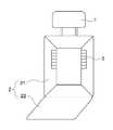
도 1은 본 발명의 일 실시예에 따른 헤드 레스트와 등받이부 사이에 배치된 송풍 장치를 나타낸 도면
도 2은 본 발명의 일 실시예에 따른 송풍 장치를 나타낸 도면
도 3은 본 발명의 일 실시예에 따른 등받이부에 배치된 송풍 장치를 나타낸 도면
도 4은 본 발명의 일 실시예에 따른 등받이부에 배치된 송풍 장치를 나타낸 도면1 is a view showing a blowing device disposed between a head rest and a backrest according to an embodiment of the present invention
2 is a view showing a blowing device according to an embodiment of the present invention
Figure 3 is a view showing a blowing device disposed on the back portion according to an embodiment of the present invention
4 is a view showing a blowing device disposed on a backrest according to an embodiment of the present invention
이하, 도면을 참조하여 본 발명의 구체적인 실시형태를 설명하기로 한다. 그러나 이는 예시에 불과하며 본 발명은 이에 제한되지 않는다.Hereinafter, specific embodiments of the present invention will be described with reference to the drawings. However, this is only an example and the present invention is not limited thereto.
본 발명을 설명함에 있어서, 본 발명과 관련된 공지기술에 대한 구체적인 설명이 본 발명의 요지를 불필요하게 흐릴 수 있다고 판단되는 경우에는 그 상세한 설명을 생략하기로 한다. 그리고, 후술되는 용어들은 본 발명에서의 기능을 고려하여 정의된 용어들로서 이는 사용자, 운용자의 의도 또는 관례 등에 따라 달라질 수 있다. 그러므로 그 정의는 본 명세서 전반에 걸친 내용을 토대로 내려져야 할 것이다.In describing the present invention, when it is determined that a detailed description of known technology related to the present invention may unnecessarily obscure the subject matter of the present invention, the detailed description will be omitted. In addition, terms to be described later are terms defined in consideration of functions in the present invention, which may vary according to a user's or operator's intention or practice. Therefore, the definition should be made based on the contents throughout this specification.
본 발명의 기술적 사상은 청구범위에 의해 결정되며, 이하의 실시예는 본 발명의 기술적 사상을 본 발명이 속하는 기술분야에서 통상의 지식을 가진 자에게 효율적으로 설명하기 위한 일 수단일 뿐이다.The technical spirit of the present invention is determined by the claims, and the following examples are merely a means for efficiently explaining the technical spirit of the present invention to those skilled in the art to which the present invention pertains.
본 발명의 일 실시예에 따르면, 차량용 송풍 시스템은 헤드 레스트(1), 시트부(2) 및 송풍 장치(3)를 포함할 수 있다. 시트부(2)는 사용자의 등을 지지하는 등받이부(21)와 사용자의 엉덩이와 허리를 지지하는 좌판부(22)를 포함할 수 있다. 또한, 송풍 장치(3)는 하나의 구성으로 일체화 될 수 있다. 일체화 되어 있는 송풍 장치(3)가 차량의 시트부(2)에 배치될 수 있다.According to an embodiment of the present invention, the vehicle air blowing system may include a
도 1 내지 도 3을 참조하면, 송풍 장치(3)는 차량의 각각의 다른 위치에 배치될 수 있다. 송풍 장치(3)는 헤드 레스트(1)와 등받이부(21) 사이에 배치될 수 있다. 송풍 장치(3)는 연결부(4)에 의해 헤드 레스트(1)와 연결되고, 헤드 레스트(1) 측에서 등받이부(21)의 내부로 연장 형성될 수 있다. 또한, 송풍 장치(3)는 등받이부(21) 내부에 배치되어 등받이부(21)의 전면부로 공기를 배출할 수 있다. 또한, 송풍 장치(3)는 좌판부(22) 내부에 배치되어 좌판부(22)의 상면부로 공기를 배출할 수 있다.1 to 3, the blowing
도 1은 본 발명의 일 실시예에 따른 헤드 레스트(1)와 등받이부(21) 사이에 배치된 송풍 장치(3)를 나타낸 도면이다.1 is a view showing a blowing
도 1을 참조하면, 송풍 장치(3)는 공기를 송풍 시키는 송풍 모듈(33), 공기를 외부로 배출하는 토출부(31) 및 송풍 모듈(33)에서 형성된 공기를 토출부(31)로 배출하는 에어 덕트(32)를 포함할 수 있다.Referring to FIG. 1, the
송풍 장치(3)는 연결부(4)에 의해 헤드 레스트(1)와 연결되고, 헤드 레스트(1) 측에서 등받이부(21)의 내부로 연장 형성될 수 있다.The
송풍 모듈(33)은 송풍 장치(3)의 말단 부위에 형성될 수 있다. 송풍 모듈(33)이 배치된 송풍 장치(3)의 말단 부위는 등받이부(21) 내부에 배치될 수 있다. 송풍 모듈(33)은 송풍팬, 히터, 열 교환핀, 열선, 온도센서 등을 포함할 수 있으며, 그 중 적어도 하나를 포함할 수 있다. 송풍팬을 통해 공기를 송풍 할 수 있으며, 히터를 통해 따뜻한 공기를 배출할 수도 있다.The blowing
토출부(31)는 공기를 외부로 배출시킬 수 있다. 토출부(31)는 헤드 레스트(1)에 고정 장착될 수 있다. 송풍 모듈(33)에서 형성된 공기가 에어 덕트(32)를 통과해서 공기를 외부로 배출시킬 수 있다. 토출부(31)는 공기를 외부로 배출할 수 있는 통공이 복수개 배열되는 형태로 형성될 수 있다.The
또한, 토출부(31)는 방향 전환부(미도시됨)를 포함할 수 있다. 상기 방향 전환부는 토출 방향을 상하 좌우로 조절할 수 있다. 따라서, 사용자가 원하는 방향으로 공기를 배출 시킬 수 있다. 상기 방향 조절부는 레버, 스위치 등을 포함할 수 있다.Also, the
에어 덕트(32)는 토출부(31)와 송풍 모듈(33) 사이에 연결 배치되어, 송풍 모듈(33)에서 형성된 공기를 토출부(31)를 통해 배출시킬 수 있다.The
송풍 장치(3)는 토출부(31), 에어 덕트(32) 및 송풍 모듈(33)을 포함하여 일체화 될 수 있다. 일체화 되어 있는 송풍 장치(3)는 헤드 레스트(1)와 연결되고, 말단 부위는 등받이부(21) 내부에 배치되어 있다. 따라서, 헤드 레스트(1)의 높이를 조절함에 따라, 송풍 장치(3)가 상하로 이동될 수 있다.The
헤드 레스트(1)에 고정되어 있는 토출부(31)는 헤드 레스트(1)의 높이 조절에 따라 같이 이동될 수 있다. 사용자가 헤드 레스트(1)의 높이를 조절하여 토출부(31)를 사용자의 목에 맞는 위치에 배치시킬 수 있다.The
사용자의 머리와 목 주변으로 공기를 공급하는 경우, 토출부(31)는 각각의 토출 통공이 기 결정된 크기로 복수개 형성될 수 있다. 상기 기 결정된 크기는 사용자의 머리와 목에 무리가 가지 않는 범위 내에서의 공기 공급량과 강도에 따라 결정될 수 있다. 만약, 사용자의 머리와 목 주변으로 공기가 한번에 강하게 많은 양이 가해지면 머리와 목에 무리가 갈 수 있다. 그러므로 공기를 분산하여 토출시키기 위해 토출 통공의 배출 면적이 좁은 형태로 되도록 하되, 전체 분사량을 확보하기 위하여 토출 통공의 개수를 복수개로 할 수 있다. 예를 들어, 토출부(31)의 가로 방향 또는 세로 방향을 따라서 폭이 좁은 사각형 형태로 복수개가 나열될 수 있다. 여기서, 토출 통공은 사각형 형태뿐만 아니라 원형 등의 형상을 포함할 수 있다.In the case of supplying air around the user's head and neck, a plurality of
도 2은 본 발명의 일 실시예에 따른 송풍 장치(3)를 나타낸 도면이다.2 is a view showing a
도 2를 참조하면, 송풍 장치(3)는 송풍 모듈(33), 토출부(31) 및 에어 덕트(32)를 포함할 수 있다. 송풍 장치(3)에서 발생된 공기는 에어 덕트(32)를 지나 토출부(31)로 배출될 수 있다. 토출부(31)는 사용자의 신체로 공기를 공급할 수 있다. 따라서, 사용자의 쾌적함을 유지할 수 있다.Referring to FIG. 2, the
송풍 장치(3)는 송풍 모듈(33)에 의해 온도 조절이 가능하다. 송풍 모듈(33) 내의 송풍팬을 이용하여 송풍 기능을 작동시켜 여름에는 땀이 차는 것을 방지할 수 있다. 또한, 겨울에는 따뜻하게 하기 위해, 송풍 모듈에 배치되는 히터, 열선 등을 작동시켜 온열 기능을 작동시킬 수 있다.The
따라서, 송풍 및 온열 기능이 가능한 송풍 장치(3)는 사용자가 장시간 운전하더라도 쾌적한 환경에서 운전할 수 있도록 할 수 있다.Therefore, the
도 3 및 도 4는 본 발명의 일 실시예에 따른 등받이부(21)에 배치된 송풍 장치(3)를 나타낸 도면이다.3 and 4 are views showing a
도 3 및 도 4를 참조하면, 시트부(2)는 등받이부(21)와 좌판부(22)를 포함할 수 있다. 송풍장치(3)가 등받이부(21) 내부에 배치될 수 있다. 토출부(31)가 등받이부(21)의 전면부에 적어도 한 개 형성될 수 있다. 또한, 등받이부(21) 내부에 배치된 송풍 장치(3)는 높이 조절부(미도시됨)에 의해 상하 이동이 가능하다. 구체적으로, 토출부(31)는 사용자 신체의 겨드랑이 부위에 맞는 위치에 양쪽으로 배치될 수 있다. 따라서, 주로 땀이 많이 나는 겨드랑이 부위로 공기를 배출시킬 수 있으며, 사용자의 등으로 골고루 공기를 배출시킬 수 있다.3 and 4, the
사용자의 등과 겨드랑이 주변으로 공기를 공급하는 경우, 토출부(31)는 각각의 토출 통공이 기 결정된 크기로 복수개 형성될 수 있다. 상기 기 결정된 크기는 사용자의 등과 겨드랑이에 무리가 가지 않는 범위 내에서의 공기 공급량과 강도에 따라 결정될 수 있다. 상대적으로 사용자의 머리와 목에 비해 등과 겨드랑이 부위는 공기가 보다 강하게 분사되어도 문제되지 않는다. 따라서, 등받이부(21)에 배치되는 토출부(31)의 토출 통공은 머리와 목 주변에 형성되는 토출부(31)의 토출 통공 보다 크게 형성될 수 있다. 특히, 기온이 올라가면 등과 겨드랑이에 땀이 잘 생기기 때문에 이를 해결하기 위해서도 등받이부(21)에서는 공기가 강하게 토출될 필요가 있을 수 있다. 예를 들어, 토출부(31)의 가로 방향 또는 세로 방향을 따라서 폭이 좁은 사각형 형태로 복수개가 나열될 수 있다. 여기서, 토출 통공은 사각형 형태뿐만 아니라 원형 등의 형상을 포함할 수 있다.When air is supplied to the user's back and armpits, a plurality of
또한, 송풍 장치(3)는 등받이부(21)의 내부뿐만 아니라, 좌판부(22)의 내부에 배치될 수 있다. 토출부(31)는 좌판부(22)의 상면부에 적어도 한 개 형성될 수 있다. 시트와 맞닿는 사용자의 엉덩이로 공기를 배출 시킬 수 있다.In addition, the
사용자의 엉덩이 주변으로 공기를 공급하는 경우, 토출부(31)는 각각의 토출 통공이 기 결정된 크기로 복수개 형성될 수 있다. 상기 기 결정된 크기는 사용자의 신체에 무리가 가지 않는 범위 내에서의 공기 공급량과 강도에 따라 결정될 수 있다. 좌판부(22)는 사용자가 착석하는 시트 이므로 토출부(31)의 토출 통공이 지나치게 크게 형성될 경우, 사용자가 좌판부(22)에 안착했을 때 불편함을 느낄 수 있다. 따라서, 사용자가 불편함을 느끼지 않고, 착석시 안락함을 유지할 수 있을 만큼의 크기로 토출 통공이 형성될 수 있다.In the case of supplying air around the user's hips, a plurality of
본 발명에 따른 송풍 장치(3)는 헤드 레스트(1)와 등받이부(21) 사이, 등받이부(21) 및 좌판부(22) 중 적어도 한 군데 이상에 형성될 수 있다.The
보다 구체적으로, 송풍 장치(3)는 헤드 레스트(1)와 연결되어 등받이부(21)와 헤드 레스트(1) 사이에 배치되는 동시에 등받이부(21)에도 배치될 수 있다. 또는, 헤드 레스트(1)와 등받이부(21) 사이에는 형성되지 않고, 등받이부(21) 또는 좌판부(22)에 배치될 수 있다.More specifically, the
일체화된 송풍 장치(3)가 상하 또는 좌우로 이동 가능하고, 외부 온도에 따라 송풍 또는 온열 기능을 작동 가능하도록 하여, 차량을 이용하는 사용자가 보다 쾌적한 환경에서 차량을 이용할 수 있다.The
자동차시트 송풍 모듈의 일 실시예에 있어서, 송풍부재가 등받이 시트에 형성되고, 히팅부재와 토출부재가 헤드레스트 측에 덕트 연결부재와 같이 형성될 수 있다.In one embodiment of the vehicle seat blowing module, a blowing member may be formed on the backrest sheet, and a heating member and a discharge member may be formed as a duct connecting member on the headrest side.
또한, 자동차시트 송풍 모듈의 다른 실시예에 있어서, 송풍부재와 히팅부재가 등받이 시트에 형성되고, 헤드레스트에 덕트 연결부재와 토출부재가 형성될 수 있다.In addition, in another embodiment of the vehicle seat blowing module, a blowing member and a heating member may be formed on the backrest sheet, and a duct connecting member and a discharge member may be formed on the headrest.
또한, 자동차시트 송풍 모듈의 또 다른 실시에에 있어서, 별도의 송풍부재 없이 자동차 송풍덕트와 연결되고, 헤드레스트에 덕트 연결부재와 토출부재가 형성될 수 있다. 그리고, 히팅부재가 등받이 시트 또는 헤드레스트에 형성될 수 있다.In addition, in another embodiment of the vehicle seat blowing module, it is connected to the vehicle blowing duct without a separate blowing member, and a duct connecting member and a discharge member may be formed in the headrest. And, a heating member may be formed on the back seat or headrest.
앞선 실시예들에 있어서, 냉온 모듈이 더 형성될 수 있고, 송풍방향 조절 가이드부가 더 형성될 수 있다.In the above embodiments, a cold / hot module may be further formed, and a blowing direction adjusting guide part may be further formed.
또한, 자동차 시트 송풍 모듈에 대한 원격제어가 가능할 수 있다. 음이온 발생기를 포함할 수 있다.In addition, remote control of the vehicle seat blowing module may be possible. It may include an anion generator.
이상에서 본 발명의 대표적인 실시예들을 상세하게 설명하였으나, 본 발명이 속하는 기술분야에서 통상의 지식을 가진 자는 상술한 실시예에 대하여 본 발명의 범주에서 벗어나지 않는 한도 내에서 다양한 변형이 가능함을 이해할 것이다. 그러므로 본 발명의 권리범위는 설명된 실시예에 국한되어 정해져서는 안 되며, 후술하는 특허청구범위뿐만 아니라 이 특허청구범위와 균등한 것들에 의해 정해져야 한다.Although the exemplary embodiments of the present invention have been described in detail above, those skilled in the art to which the present invention pertains will understand that various modifications are possible within the limits without departing from the scope of the present invention. . Therefore, the scope of rights of the present invention should not be limited to the described embodiments, and should be determined not only by the claims to be described later, but also by the claims and equivalents.
1 : 헤드 레스트
2 : 시트부
21 : 등받이부
22 : 좌판부
3 : 송풍 장치
31 : 토출부
32 : 에어 덕트
33 : 송풍 모듈
4 : 연결부1: Head rest
2: Sheet portion
21: backrest
22: seat plate
3: Blower
31: discharge unit
32: air duct
33: blowing module
4: Connection
Claims (16)
Translated fromKorean상기 사용자의 머리를 지지하는 헤드 레스트;
상기 사용자 측으로 송풍 가능한 송풍 장치;를 포함하고,
상기 송풍 장치는,
공기를 송풍 시키는 송풍 모듈;
상기 공기를 외부로 배출하는 토출부; 및
상기 송풍 모듈에서 형성된 공기를 상기 토출부로 배출하는 에어 덕트;
를 포함하는 차량용 송풍 시스템.A seat portion including a backrest portion supporting a user's back and a seat plate portion supporting the user's hips and waist;
A head rest supporting the user's head;
Includes; a blowing device capable of blowing to the user side,
The blowing device,
A blowing module for blowing air;
A discharge unit for discharging the air to the outside; And
An air duct for discharging air formed in the blowing module to the discharge part;
Vehicle ventilation system comprising a.
상기 송풍 장치는 연결부에 의해 상기 헤드 레스트와 연결되고, 상기 헤드 레스트 측에서 상기 등받이부의 내부로 연장 형성되며,
상기 토출부는 상기 헤드 레스트에 고정 장착되고,
상기 송풍 모듈은 상기 등받이부 내부로 연장 형성되어 있는 상기 송풍 장치의 말단에 배치되는 차량용 송풍 시스템.The method according to claim 1,
The blowing device is connected to the headrest by a connecting portion, and is formed extending from the headrest side to the inside of the backrest portion,
The discharge portion is fixedly mounted to the head rest,
The blowing module is a vehicle blowing system that is disposed at the end of the blowing device is formed extending into the back portion.
상기 헤드 레스트의 높이 조절에 따라, 상기 송풍 장치가 상기 헤드 레스트와 함께 상하로 이동 가능한 차량용 송풍 시스템.The method according to claim 2,
According to the height adjustment of the head rest, the air blowing system for the vehicle can be moved up and down together with the head rest.
상기 송풍 모듈은 송풍팬, 히터, 열 교환핀, 온도센서 중 적어도 하나를 포함하는 차량용 송풍 시스템.The method according to claim 1,
The blower module is a blower system for a vehicle comprising at least one of a blower fan, a heater, a heat exchange pin, and a temperature sensor.
상기 토출부는 방향 전환부를 포함하여 상하 좌우로 토출 방향을 조절 가능한 차량용 송풍 시스템.The method according to claim 1,
The discharge unit includes a direction switching unit for a vehicle blowing system that can adjust the discharge direction up and down and left and right.
상기 등받이부 내부에 상기 송풍 장치가 배치되고,
상기 토출부가 상기 등받이부의 전면부에 적어도 한 개 형성되는 차량용 송풍 시스템.The method according to claim 1,
The blowing device is disposed inside the backrest,
Blowing system for a vehicle, wherein at least one discharge portion is formed on a front portion of the backrest portion.
상기 등받이부 내부에 배치되는 송풍 장치는 높이 조절부에 의해 상하 이동 가능한 차량용 송풍 시스템.The method according to claim 6,
The blowing device disposed inside the backrest is a vehicle blowing system that can be moved up and down by a height adjustment unit.
상기 좌판부 내부에 상기 송풍 장치가 배치되고,
상기 토출부가 상기 좌판부의 상면부에 적어도 한 개 형성되는 차량용 송풍 시스템.The method according to claim 1,
The blowing device is disposed inside the seat plate,
At least one discharge unit is formed on the upper surface of the seat plate vehicle blowing system.
히팅부재와 토출부재가 헤드레스트 측에 덕트 연결부재와 같이 형성되는, 자동차시트 송풍 모듈.The blowing member is formed on the back seat,
The heating member and the discharge member are formed with a duct connecting member on the headrest side, the vehicle seat blowing module.
헤드레스트에 덕트 연결부재와 토출부재가 형성되는, 자동차시트 송풍 모듈.The blowing member and the heating member are formed on the back seat,
A car seat blowing module in which a duct connecting member and a discharge member are formed in the headrest.
헤드레스트에 덕트 연결부재와 토출부재가 형성되는, 자동차시트 송풍 모듈.It is connected to the car duct,
A car seat blowing module in which a duct connecting member and a discharge member are formed in the headrest.
히팅부재가 등받이 시트 또는 헤드레스트에 형성되는, 자동차시트 송풍 모듈.The method according to claim 11,
Automotive seat blowing module, the heating member is formed on the back seat or headrest.
냉온 모듈이 더 형성되는, 자동차 시트 송풍 모듈.The method according to any one of claims 9 to 11,
A car seat blowing module further comprising a cold / hot module.
송풍방향 조절 가이드부가 더 형성되는, 자동차 시트 송풍 모듈.The method according to any one of claims 9 to 11,
Blowing direction adjustment guide portion is further formed, car seat blowing module.
원격제어 가능한, 자동차 시트 송풍 모듈.The method according to any one of claims 9 to 11,
Remote controllable, car seat blowing module.
음이온 발생기가 더 형성되는, 자동차 시트 송풍 모듈.
The method according to any one of claims 9 to 11,
An anion generator is further formed, a car seat blowing module.
Priority Applications (1)
| Application Number | Priority Date | Filing Date | Title |
|---|---|---|---|
| KR1020180110265AKR20200031351A (en) | 2018-09-14 | 2018-09-14 | Blower system for vechicle |
Applications Claiming Priority (1)
| Application Number | Priority Date | Filing Date | Title |
|---|---|---|---|
| KR1020180110265AKR20200031351A (en) | 2018-09-14 | 2018-09-14 | Blower system for vechicle |
Publications (1)
| Publication Number | Publication Date |
|---|---|
| KR20200031351Atrue KR20200031351A (en) | 2020-03-24 |
Family
ID=70004547
Family Applications (1)
| Application Number | Title | Priority Date | Filing Date |
|---|---|---|---|
| KR1020180110265AWithdrawnKR20200031351A (en) | 2018-09-14 | 2018-09-14 | Blower system for vechicle |
Country Status (1)
| Country | Link |
|---|---|
| KR (1) | KR20200031351A (en) |
Cited By (1)
| Publication number | Priority date | Publication date | Assignee | Title |
|---|---|---|---|---|
| WO2023127260A1 (en)* | 2021-12-27 | 2023-07-06 | パナソニックIpマネジメント株式会社 | Seat air-conditioning device |
Citations (1)
| Publication number | Priority date | Publication date | Assignee | Title |
|---|---|---|---|---|
| KR200444437Y1 (en) | 2007-04-30 | 2009-05-14 | 차찬열 | Air seat with blowing and warming function |
- 2018
- 2018-09-14KRKR1020180110265Apatent/KR20200031351A/ennot_activeWithdrawn
Patent Citations (1)
| Publication number | Priority date | Publication date | Assignee | Title |
|---|---|---|---|---|
| KR200444437Y1 (en) | 2007-04-30 | 2009-05-14 | 차찬열 | Air seat with blowing and warming function |
Cited By (1)
| Publication number | Priority date | Publication date | Assignee | Title |
|---|---|---|---|---|
| WO2023127260A1 (en)* | 2021-12-27 | 2023-07-06 | パナソニックIpマネジメント株式会社 | Seat air-conditioning device |
Similar Documents
| Publication | Publication Date | Title |
|---|---|---|
| US7467823B2 (en) | Vehicle seat | |
| US10543761B2 (en) | Air supply component for use with a seat | |
| EP2607155B1 (en) | Airflow management system for vehicle seat | |
| KR101836664B1 (en) | Operation control method of cold and warm headrest for vehicle | |
| JP2004215748A (en) | Air-conditioner for vehicle | |
| US10160354B2 (en) | Vehicle air-conditioning seat | |
| KR20120121854A (en) | System and method of providing quick thermal comfort with reduced energy by using directed spot conditioning | |
| US20190283636A1 (en) | Vehicle air conditioning system | |
| JP2015089467A (en) | Blast seat for vehicle | |
| WO2016104208A1 (en) | Ventilated seat | |
| WO2022091661A1 (en) | Seat air-conditioning device | |
| GB2511330A (en) | Air Guiding Device Of A Vehicle | |
| CN104842839A (en) | Self-adaptive temperature adjusting seat structure of automobile | |
| KR20200031351A (en) | Blower system for vechicle | |
| JP2010023533A (en) | Vehicular heating device | |
| KR20160139839A (en) | Seat for car with function of cold wind and warm wind | |
| KR20160139841A (en) | Seat for car with function of cold wind and warm wind | |
| KR101636391B1 (en) | Seat for vehicle | |
| WO2012042302A1 (en) | Air conditioning assembly | |
| KR20160104878A (en) | Headrest with function of cold wind and warm wind | |
| KR20160139837A (en) | Seat for car with function of cold wind and warm wind | |
| KR101251137B1 (en) | Cooling and heating apparatus for vehicle seat | |
| US20150274046A1 (en) | Seat climate control assembly and seat employing the same | |
| JP6640642B2 (en) | Vehicle air conditioner | |
| JP6983678B2 (en) | Vehicle air conditioner |
Legal Events
| Date | Code | Title | Description |
|---|---|---|---|
| PA0109 | Patent application | Patent event code:PA01091R01D Comment text:Patent Application Patent event date:20180914 | |
| PG1501 | Laying open of application | ||
| PC1203 | Withdrawal of no request for examination |