KR20200031105A - Method and apparatus for manufacturing 3D molded product using spectrum converter - Google Patents
Method and apparatus for manufacturing 3D molded product using spectrum converterDownload PDFInfo
- Publication number
- KR20200031105A KR20200031105AKR1020207001896AKR20207001896AKR20200031105AKR 20200031105 AKR20200031105 AKR 20200031105AKR 1020207001896 AKR1020207001896 AKR 1020207001896AKR 20207001896 AKR20207001896 AKR 20207001896AKR 20200031105 AKR20200031105 AKR 20200031105A
- Authority
- KR
- South Korea
- Prior art keywords
- powder
- manufacturing
- radiation
- molded article
- temperature
- Prior art date
- Legal status (The legal status is an assumption and is not a legal conclusion. Google has not performed a legal analysis and makes no representation as to the accuracy of the status listed.)
- Granted
Links
Images


Classifications
- B—PERFORMING OPERATIONS; TRANSPORTING
- B29—WORKING OF PLASTICS; WORKING OF SUBSTANCES IN A PLASTIC STATE IN GENERAL
- B29C—SHAPING OR JOINING OF PLASTICS; SHAPING OF MATERIAL IN A PLASTIC STATE, NOT OTHERWISE PROVIDED FOR; AFTER-TREATMENT OF THE SHAPED PRODUCTS, e.g. REPAIRING
- B29C64/00—Additive manufacturing, i.e. manufacturing of three-dimensional [3D] objects by additive deposition, additive agglomeration or additive layering, e.g. by 3D printing, stereolithography or selective laser sintering
- B29C64/20—Apparatus for additive manufacturing; Details thereof or accessories therefor
- B29C64/264—Arrangements for irradiation
- B29C64/268—Arrangements for irradiation using laser beams; using electron beams [EB]
- B—PERFORMING OPERATIONS; TRANSPORTING
- B29—WORKING OF PLASTICS; WORKING OF SUBSTANCES IN A PLASTIC STATE IN GENERAL
- B29C—SHAPING OR JOINING OF PLASTICS; SHAPING OF MATERIAL IN A PLASTIC STATE, NOT OTHERWISE PROVIDED FOR; AFTER-TREATMENT OF THE SHAPED PRODUCTS, e.g. REPAIRING
- B29C64/00—Additive manufacturing, i.e. manufacturing of three-dimensional [3D] objects by additive deposition, additive agglomeration or additive layering, e.g. by 3D printing, stereolithography or selective laser sintering
- B29C64/20—Apparatus for additive manufacturing; Details thereof or accessories therefor
- B29C64/264—Arrangements for irradiation
- B29C64/286—Optical filters, e.g. masks
- B—PERFORMING OPERATIONS; TRANSPORTING
- B29—WORKING OF PLASTICS; WORKING OF SUBSTANCES IN A PLASTIC STATE IN GENERAL
- B29C—SHAPING OR JOINING OF PLASTICS; SHAPING OF MATERIAL IN A PLASTIC STATE, NOT OTHERWISE PROVIDED FOR; AFTER-TREATMENT OF THE SHAPED PRODUCTS, e.g. REPAIRING
- B29C64/00—Additive manufacturing, i.e. manufacturing of three-dimensional [3D] objects by additive deposition, additive agglomeration or additive layering, e.g. by 3D printing, stereolithography or selective laser sintering
- B29C64/10—Processes of additive manufacturing
- B29C64/141—Processes of additive manufacturing using only solid materials
- B29C64/153—Processes of additive manufacturing using only solid materials using layers of powder being selectively joined, e.g. by selective laser sintering or melting
- B—PERFORMING OPERATIONS; TRANSPORTING
- B29—WORKING OF PLASTICS; WORKING OF SUBSTANCES IN A PLASTIC STATE IN GENERAL
- B29C—SHAPING OR JOINING OF PLASTICS; SHAPING OF MATERIAL IN A PLASTIC STATE, NOT OTHERWISE PROVIDED FOR; AFTER-TREATMENT OF THE SHAPED PRODUCTS, e.g. REPAIRING
- B29C64/00—Additive manufacturing, i.e. manufacturing of three-dimensional [3D] objects by additive deposition, additive agglomeration or additive layering, e.g. by 3D printing, stereolithography or selective laser sintering
- B29C64/10—Processes of additive manufacturing
- B29C64/165—Processes of additive manufacturing using a combination of solid and fluid materials, e.g. a powder selectively bound by a liquid binder, catalyst, inhibitor or energy absorber
- B—PERFORMING OPERATIONS; TRANSPORTING
- B29—WORKING OF PLASTICS; WORKING OF SUBSTANCES IN A PLASTIC STATE IN GENERAL
- B29C—SHAPING OR JOINING OF PLASTICS; SHAPING OF MATERIAL IN A PLASTIC STATE, NOT OTHERWISE PROVIDED FOR; AFTER-TREATMENT OF THE SHAPED PRODUCTS, e.g. REPAIRING
- B29C64/00—Additive manufacturing, i.e. manufacturing of three-dimensional [3D] objects by additive deposition, additive agglomeration or additive layering, e.g. by 3D printing, stereolithography or selective laser sintering
- B29C64/20—Apparatus for additive manufacturing; Details thereof or accessories therefor
- B29C64/205—Means for applying layers
- B29C64/209—Heads; Nozzles
- B—PERFORMING OPERATIONS; TRANSPORTING
- B29—WORKING OF PLASTICS; WORKING OF SUBSTANCES IN A PLASTIC STATE IN GENERAL
- B29C—SHAPING OR JOINING OF PLASTICS; SHAPING OF MATERIAL IN A PLASTIC STATE, NOT OTHERWISE PROVIDED FOR; AFTER-TREATMENT OF THE SHAPED PRODUCTS, e.g. REPAIRING
- B29C64/00—Additive manufacturing, i.e. manufacturing of three-dimensional [3D] objects by additive deposition, additive agglomeration or additive layering, e.g. by 3D printing, stereolithography or selective laser sintering
- B29C64/20—Apparatus for additive manufacturing; Details thereof or accessories therefor
- B29C64/245—Platforms or substrates
- B—PERFORMING OPERATIONS; TRANSPORTING
- B29—WORKING OF PLASTICS; WORKING OF SUBSTANCES IN A PLASTIC STATE IN GENERAL
- B29C—SHAPING OR JOINING OF PLASTICS; SHAPING OF MATERIAL IN A PLASTIC STATE, NOT OTHERWISE PROVIDED FOR; AFTER-TREATMENT OF THE SHAPED PRODUCTS, e.g. REPAIRING
- B29C64/00—Additive manufacturing, i.e. manufacturing of three-dimensional [3D] objects by additive deposition, additive agglomeration or additive layering, e.g. by 3D printing, stereolithography or selective laser sintering
- B29C64/20—Apparatus for additive manufacturing; Details thereof or accessories therefor
- B29C64/264—Arrangements for irradiation
- B29C64/291—Arrangements for irradiation for operating globally, e.g. together with selectively applied activators or inhibitors
- B—PERFORMING OPERATIONS; TRANSPORTING
- B29—WORKING OF PLASTICS; WORKING OF SUBSTANCES IN A PLASTIC STATE IN GENERAL
- B29C—SHAPING OR JOINING OF PLASTICS; SHAPING OF MATERIAL IN A PLASTIC STATE, NOT OTHERWISE PROVIDED FOR; AFTER-TREATMENT OF THE SHAPED PRODUCTS, e.g. REPAIRING
- B29C64/00—Additive manufacturing, i.e. manufacturing of three-dimensional [3D] objects by additive deposition, additive agglomeration or additive layering, e.g. by 3D printing, stereolithography or selective laser sintering
- B29C64/20—Apparatus for additive manufacturing; Details thereof or accessories therefor
- B29C64/295—Heating elements
- B—PERFORMING OPERATIONS; TRANSPORTING
- B29—WORKING OF PLASTICS; WORKING OF SUBSTANCES IN A PLASTIC STATE IN GENERAL
- B29C—SHAPING OR JOINING OF PLASTICS; SHAPING OF MATERIAL IN A PLASTIC STATE, NOT OTHERWISE PROVIDED FOR; AFTER-TREATMENT OF THE SHAPED PRODUCTS, e.g. REPAIRING
- B29C64/00—Additive manufacturing, i.e. manufacturing of three-dimensional [3D] objects by additive deposition, additive agglomeration or additive layering, e.g. by 3D printing, stereolithography or selective laser sintering
- B29C64/30—Auxiliary operations or equipment
- B29C64/386—Data acquisition or data processing for additive manufacturing
- B29C64/393—Data acquisition or data processing for additive manufacturing for controlling or regulating additive manufacturing processes
- B—PERFORMING OPERATIONS; TRANSPORTING
- B33—ADDITIVE MANUFACTURING TECHNOLOGY
- B33Y—ADDITIVE MANUFACTURING, i.e. MANUFACTURING OF THREE-DIMENSIONAL [3-D] OBJECTS BY ADDITIVE DEPOSITION, ADDITIVE AGGLOMERATION OR ADDITIVE LAYERING, e.g. BY 3-D PRINTING, STEREOLITHOGRAPHY OR SELECTIVE LASER SINTERING
- B33Y50/00—Data acquisition or data processing for additive manufacturing
- B33Y50/02—Data acquisition or data processing for additive manufacturing for controlling or regulating additive manufacturing processes
- B—PERFORMING OPERATIONS; TRANSPORTING
- B22—CASTING; POWDER METALLURGY
- B22F—WORKING METALLIC POWDER; MANUFACTURE OF ARTICLES FROM METALLIC POWDER; MAKING METALLIC POWDER; APPARATUS OR DEVICES SPECIALLY ADAPTED FOR METALLIC POWDER
- B22F10/00—Additive manufacturing of workpieces or articles from metallic powder
- B22F10/20—Direct sintering or melting
- B22F10/28—Powder bed fusion, e.g. selective laser melting [SLM] or electron beam melting [EBM]
- B—PERFORMING OPERATIONS; TRANSPORTING
- B29—WORKING OF PLASTICS; WORKING OF SUBSTANCES IN A PLASTIC STATE IN GENERAL
- B29K—INDEXING SCHEME ASSOCIATED WITH SUBCLASSES B29B, B29C OR B29D, RELATING TO MOULDING MATERIALS OR TO MATERIALS FOR MOULDS, REINFORCEMENTS, FILLERS OR PREFORMED PARTS, e.g. INSERTS
- B29K2075/00—Use of PU, i.e. polyureas or polyurethanes or derivatives thereof, as moulding material
- B—PERFORMING OPERATIONS; TRANSPORTING
- B29—WORKING OF PLASTICS; WORKING OF SUBSTANCES IN A PLASTIC STATE IN GENERAL
- B29K—INDEXING SCHEME ASSOCIATED WITH SUBCLASSES B29B, B29C OR B29D, RELATING TO MOULDING MATERIALS OR TO MATERIALS FOR MOULDS, REINFORCEMENTS, FILLERS OR PREFORMED PARTS, e.g. INSERTS
- B29K2077/00—Use of PA, i.e. polyamides, e.g. polyesteramides or derivatives thereof, as moulding material
- B—PERFORMING OPERATIONS; TRANSPORTING
- B33—ADDITIVE MANUFACTURING TECHNOLOGY
- B33Y—ADDITIVE MANUFACTURING, i.e. MANUFACTURING OF THREE-DIMENSIONAL [3-D] OBJECTS BY ADDITIVE DEPOSITION, ADDITIVE AGGLOMERATION OR ADDITIVE LAYERING, e.g. BY 3-D PRINTING, STEREOLITHOGRAPHY OR SELECTIVE LASER SINTERING
- B33Y10/00—Processes of additive manufacturing
- B—PERFORMING OPERATIONS; TRANSPORTING
- B33—ADDITIVE MANUFACTURING TECHNOLOGY
- B33Y—ADDITIVE MANUFACTURING, i.e. MANUFACTURING OF THREE-DIMENSIONAL [3-D] OBJECTS BY ADDITIVE DEPOSITION, ADDITIVE AGGLOMERATION OR ADDITIVE LAYERING, e.g. BY 3-D PRINTING, STEREOLITHOGRAPHY OR SELECTIVE LASER SINTERING
- B33Y30/00—Apparatus for additive manufacturing; Details thereof or accessories therefor
- G—PHYSICS
- G02—OPTICS
- G02B—OPTICAL ELEMENTS, SYSTEMS OR APPARATUS
- G02B5/00—Optical elements other than lenses
- G02B5/20—Filters
- G02B5/208—Filters for use with infrared or ultraviolet radiation, e.g. for separating visible light from infrared and/or ultraviolet radiation
- H—ELECTRICITY
- H04—ELECTRIC COMMUNICATION TECHNIQUE
- H04N—PICTORIAL COMMUNICATION, e.g. TELEVISION
- H04N1/00—Scanning, transmission or reproduction of documents or the like, e.g. facsimile transmission; Details thereof
- H04N1/40—Picture signal circuits
- H04N1/40056—Circuits for driving or energising particular reading heads or original illumination means
- H—ELECTRICITY
- H04—ELECTRIC COMMUNICATION TECHNIQUE
- H04N—PICTORIAL COMMUNICATION, e.g. TELEVISION
- H04N1/00—Scanning, transmission or reproduction of documents or the like, e.g. facsimile transmission; Details thereof
- H04N1/46—Colour picture communication systems
- H04N1/56—Processing of colour picture signals
- H04N1/60—Colour correction or control
- Y—GENERAL TAGGING OF NEW TECHNOLOGICAL DEVELOPMENTS; GENERAL TAGGING OF CROSS-SECTIONAL TECHNOLOGIES SPANNING OVER SEVERAL SECTIONS OF THE IPC; TECHNICAL SUBJECTS COVERED BY FORMER USPC CROSS-REFERENCE ART COLLECTIONS [XRACs] AND DIGESTS
- Y02—TECHNOLOGIES OR APPLICATIONS FOR MITIGATION OR ADAPTATION AGAINST CLIMATE CHANGE
- Y02P—CLIMATE CHANGE MITIGATION TECHNOLOGIES IN THE PRODUCTION OR PROCESSING OF GOODS
- Y02P10/00—Technologies related to metal processing
- Y02P10/25—Process efficiency
Landscapes
- Engineering & Computer Science (AREA)
- Chemical & Material Sciences (AREA)
- Materials Engineering (AREA)
- Manufacturing & Machinery (AREA)
- Physics & Mathematics (AREA)
- Optics & Photonics (AREA)
- Mechanical Engineering (AREA)
- Health & Medical Sciences (AREA)
- Toxicology (AREA)
- Plasma & Fusion (AREA)
Abstract
Translated fromKoreanDescription
Translated fromKorean본 발명은 층 제작 기술(layer construction technique)에 의해 3차원 모델을 생성하는 방법 및 장치에 관한 것이다.The present invention relates to a method and apparatus for generating a three-dimensional model by layer construction technique.
유럽 특허 EP 0 431 924 B1은 컴퓨터 데이터를 기반으로 3차원 물체를 생성하는 공정을 기술하고 있다. 이 공정에서, 얇은 미립자 재료 층이 플랫폼 상에 증착되고, 그 위에 프린트 헤드에 의해 선택적으로 프린트되는 결합제(binder) 재료를 갖는다. 결합제가 상부에 프린트된 미립자 영역은 결합제 및 선택적으로 추가의 경화제(hardener)의 영향 하에 결합되고 응고된다. 그 다음, 플랫폼은 하나의 층 두께만큼 제작 실린더(construction cylinder) 내부로 하강하고 새로운 미립자 재료 층이 제공되며, 이 미립자 재료 층은 또한 상기한 바와 같이 프린트된다. 이들 단계는 물체의 원하는 특정 높이에 도달할 때까지 반복된다. 따라서, 프린트되고 응고된 영역은 3차원 물체를 형성한다.European patent EP 0 431 924 B1 describes a process for generating three-dimensional objects based on computer data. In this process, a thin layer of particulate material is deposited on the platform and has a binder material thereon that is selectively printed by the print head. Particulate regions on which the binder is printed are bound and solidified under the influence of the binder and, optionally, additional hardeners. The platform is then lowered into the construction cylinder by one layer thickness and a new layer of particulate material is provided, which is also printed as described above. These steps are repeated until the desired specific height of the object is reached. Thus, the printed and solidified area forms a three-dimensional object.
완료되면, 응고된 미립자 재료로 제조된 물체는 느슨한 미립자 재료에 끼워지고, 이후 이로부터 빼내어진다. 이를 위해, 예를 들어 흡입 장치가 사용될 수 있다. 이는 원하는 물체를 남기고, 물체는 예를 들어 솔질에 의해 잔류 분말이 없어야 한다.Upon completion, the object made of the solidified particulate material is fitted into the loose particulate material and then withdrawn from it. For this, for example, an inhalation device can be used. This leaves the desired object, and the object should be free of residual powder, for example by brushing.
예를 들어, 선택적 레이저 소결(selective laser sintering) 또는 전자빔 소결(electron beam sintering)과 같은 다른 분말-기반의 신속한 프로토타이핑 공정(prototyping process)(모델의 층상 구조(layered construction) 또는 층 제작 기술이라고도 함)이 유사한 방식으로 작동하고, 또한 느슨한 미립자 재료를 층별로 도포하고, 제어된 물리적 방사선원(controlled physical source of radiation)의 도움으로 이를 선택적으로 응고시킨다.Other powder-based rapid prototyping processes, such as, for example, selective laser sintering or electron beam sintering (also called layered construction or layer fabrication techniques in the model) ) Works in a similar manner, and also applies loose particulate material layer by layer and selectively solidifies it with the help of a controlled physical source of radiation.
이하에서, 이들 모든 공정은 "3차원 프린팅 방법" 또는 "3D 프린팅 방법"이라는 용어에 포함되는 것으로 이해될 것이다.In the following, it will be understood that all of these processes are included in the term "three-dimensional printing method" or "3D printing method".
분말 재료 및 액체 결합제의 도입을 기반으로 하는 3D 프린팅은 층 제작 기술 중에서 가장 신속한 방법이다.3D printing based on the introduction of powder materials and liquid binders is the fastest method of layer making technology.
이 방법은 중합체 재료를 포함하는 다양한 미립자 재료를 처리할 수 있다. 그러나, 미립자 재료 층은 일반적으로 입자 밀도의 60%인 특정 부피 밀도를 초과할 수 없다는 단점을 갖는다. 그러나, 원하는 부품의 강도는 달성된 밀도에 따라 크게 달라진다. 지금까지는 부품의 고강도를 위해 액체 결합제의 형태로 40 부피% 이상의 미립자 재료를 첨가하는 것이 필요하다. 이는 단일-액적 투입으로 인해 비교적 시간 소모적인 공정일 뿐만 아니라, 예를 들어, 응고 동안 액체 부피의 불가피한 수축에 의해 유발되는 많은 공정 관련 문제를 야기한다.This method can process a variety of particulate materials, including polymeric materials. However, the particulate material layer has the disadvantage that it cannot exceed a certain bulk density, which is generally 60% of the particle density. However, the strength of the desired component is highly dependent on the density achieved. Up to now, it is necessary to add at least 40% by volume of particulate material in the form of a liquid binder for high strength of the part. This is not only a relatively time consuming process due to single-droplet addition, but also creates many process related problems caused by, for example, the unavoidable shrinkage of the liquid volume during solidification.
본 기술 분야에서 "고속 소결"로 알려진 또 다른 실시형태에서, 미립자 재료의 응고는 적외선 방사의 투입에 의해 달성된다. 따라서, 미립자 재료는 융합 공정(fusing process)에 의해 물리적으로 결합된다. 이 경우, 무색 플라스틱 재료에서의 열 복사의 비교적 낮은 흡수를 이용한다. 상기 흡수는 플라스틱 재료에 IR 수용체(IR acceptor)(흡수제(absorber))를 도입함으로써 몇 배 증가될 수 있다. IR 방사(IR radiation)는 다양한 수단, 예를 들어, 제작장(construction field) 위에서 고르게 이동하는 막대 모양의 IR 램프에 의해 도입될 수 있다. 선택성은 IR 수용체를 갖는 각각의 층에 대한 특수 프린팅에 의해 달성된다.In another embodiment known in the art as "high-speed sintering", solidification of the particulate material is achieved by the input of infrared radiation. Thus, the particulate material is physically bonded by a fusing process. In this case, a relatively low absorption of thermal radiation in a colorless plastic material is used. The absorption can be increased several times by introducing an IR acceptor (absorber) into the plastic material. IR radiation can be introduced by various means, for example, a rod-shaped IR lamp that moves evenly over a construction field. Selectivity is achieved by special printing for each layer with IR receptors.
프린트된 위치에서, IR 방사는 따라서 프린트되지 않은 영역보다 미립자 재료에 훨씬 더 잘 결합된다. 이는 융점 이상에서 층 내부의 선택적인 가열을 초래하고, 결과적으로 선택적인 응고를 초래한다. 이 공정은 예를 들어 EP1740367B1 및 EP1648686B1에 기술되어 있으며, 아래에서 HSS로 약칭한다.In the printed position, the IR radiation is thus much better bonded to the particulate material than the unprinted area. This leads to selective heating inside the layer above the melting point, and consequently to selective solidification. This process is described in EP1740367B1 and EP1648686B1, for example, abbreviated as HSS below.
이 방법으로도 처리될 수 있는 다양한 재료가 레이저 소결 공정에서 알려져 있다. 이 맥락에서 가장 중요한 재료는 폴리아미드 12(polyamide 12)이다. 이 재료는 여러 제조업체에서 생산된다. 달성된 강도는 층 제작 방법에서 탁월하다.Various materials that can also be treated with this method are known in laser sintering processes. The most important material in this context is polyamide 12. This material is produced by several manufacturers. The achieved strength is excellent in the layer making method.
재료는 이러한 품질로 직접 처리될 수 있는 미세 분말로 구할 수 있다. 그러나, 제조 공정으로 인해, 비용이 높고 표준 폴리아미드의 비용을 20 내지 30 배까지 초과할 수 있다.The material can be obtained as a fine powder that can be treated directly with this quality. However, due to the manufacturing process, it is expensive and can exceed the cost of standard polyamides by 20 to 30 times.
선행 기술에 따른 고속 소결 공정에서, 레이저 소결에서와 같이, 분말은 처리용 재료의 융점 근처의 온도에 놓인다. 이는 분말을 "시효(age)"시키고 후속 공정에서 분말의 사용을 제한한다. 재활용률이 낮아지는데, 이는 공정 비용에 부정적인 영향을 미친다.In the high-speed sintering process according to the prior art, as in laser sintering, the powder is placed at a temperature near the melting point of the material for processing. This “ages” the powder and limits its use in subsequent processes. The recycling rate is lowered, which negatively affects the process cost.
부품의 정밀도는 공정 제어에 의해 크게 영향을 받는다. 따라서, 분말 층 밀도 및 제작 공간의 온도와 같은 파라미터의 균일성은 결정적이다.The precision of the parts is greatly influenced by process control. Accordingly, uniformity of parameters such as powder layer density and temperature of the production space is crucial.
공지된 고속 소결 방법은 한편으로는 재활용률 및 다른 한편으로는 공정 비용에 관한 많은 단점을 가지며, 결과적으로 부품당 비용을 증가시키고 부품을 상당히 비싸게 만든다. 특히, 분말의 시효는 중요한 문제이며, 이에 따른 낮은 재활용률은 이 공정의 확산에 있어서 큰 장애가 된다. 현재, 프린트되지 않은 분말의 대략 50%는 공정 후 교체되어야 한다. 대략 €80/kg의 분말 가격 및 수백 리터의 제작 부피로 인해, 이는 많은 재정 투자를 필요로 한다.Known high-speed sintering methods have, on the one hand, many disadvantages with regard to recycling rates and, on the other hand, process costs, which in turn increases the cost per part and makes the part considerably expensive. In particular, aging of the powder is an important problem, and the low recycling rate accordingly is a major obstacle to the diffusion of this process. Currently, approximately 50% of the unprinted powder needs to be replaced after processing. Due to the powder price of approximately € 80 / kg and the production volume of hundreds of liters, this requires a lot of financial investment.
공정 관련 문제를 해결함으로써 비용을 절감하는 한 가지 방법은 덜 비싼 분말을 사용하는 것이다. 그러나, 대부분의 분말은 안전하게 처리될 수 있는 충분한 "소결 창(sintering window)"을 갖지 않기 때문에 이 방법에는 약간의 한계가 있다. 이는 이러한 분말에 대해 안정적인 공정 파라미터를 찾기 어렵다는 것을 의미한다.One way to save money by solving process problems is to use less expensive powders. However, this method has some limitations because most powders do not have enough "sintering windows" that can be safely processed. This means that it is difficult to find stable process parameters for these powders.
또 다른 방법은 분말 시효를 화학적으로 제한하는 것이다. 이 경우, 예를 들어, 레이저 소결에서는 기계를 질소로 세척하는 것이 일반적이다. 이는 분말 산화를 방지할 수 있다. 그러나, 공정 관련 이유만으로, 시효를 완전히 억제할 수 없는데, 이는 응고 반응의 일부가 중합체의 2차 반응에 의해 발생하기 때문이다. 이러한 2차 반응을 억제하는 것은 강도 측면에서 근본적인 한계를 의미할 수 있다.Another method is to chemically limit powder aging. In this case, for example, in laser sintering, it is common to wash the machine with nitrogen. This can prevent powder oxidation. However, for process-related reasons alone, aging cannot be completely suppressed, because part of the coagulation reaction is caused by the secondary reaction of the polymer. Inhibiting these secondary reactions may mean fundamental limitations in terms of strength.
공지된 고속 소결 방법의 한 가지 과제는, 예를 들어, 사용된 미립자 재료에 대한 온도 창(temperature window)과 같은 유리한 공정 조건에 대한 조정이다. 고속 소결 방법은 다수의 공정 파라미터를 조합하고, 여기에 사용되는 3D 프린팅 기계는 수많은 구성적인 특징과 구성요소를 갖는데, 이는 적절한 구성요소를 조합하고 유리하거나 개선된 공정 순서를 조정하여 개선된 공정 조건을 제공하는 것을 어렵게 한다. 많은 경우, 양호한 공정 결과를 달성하고 고품질의 3D 부품을 획득하고 및/또는 공정을 최적화하기 위해 어떤 구성적인 변경이 필요한지 결정하는 것은 불가능하다.One challenge of the known high-speed sintering method is adjustment to favorable process conditions, such as, for example, a temperature window for the particulate material used. The high-speed sintering method combines a number of process parameters, and the 3D printing machine used therein has a number of constitutive features and components, which improve the process conditions by combining suitable components and adjusting advantageous or improved process sequences. It makes it difficult to provide. In many cases, it is impossible to determine what constitutive changes are needed to achieve good process results, obtain high quality 3D parts and / or optimize the process.
공정 조건을 조정하는 데 있어서의 또 다른 과제는, 한편으로는 충분히 강한 구성요소가 바람직하고 유리한 특성을 갖도록 제조되도록 하는 동시에, 응고되지 않는 미립자 재료가 쉽게 해체될 수 있게 하는 공정 조건에 놓이도록 공정 조건을 조합하는 것이다. 이와 관련한 한 가지 문제점은 주변 재료가 공정에서 너무 많이 응고되고, 따라서 구성요소로부터 이를 제거하는 것이 어렵고, 그렇게 하기 위해서는 많은 노력이 필요하다는 점이다.Another challenge in adjusting process conditions is, on the one hand, to ensure that sufficiently strong components are manufactured to have desirable and advantageous properties, while at the same time subjecting them to process conditions that allow the unsolidified particulate material to be easily dismantled. It is a combination of conditions. One problem with this is that the surrounding material solidifies too much in the process, so it is difficult to remove it from the component, and a lot of effort is required to do so.
추가의 과제는 고속 소결 공정 3D 프린팅 공정을 위해 설치될 수 있는 종래의 IR 방사기(IR radiator)의 방사 특성이다.A further challenge is the radiation properties of conventional IR radiators that can be installed for high-speed sintering processes 3D printing processes.
열에 의해 작동하는 종래의 IR 방사기의 방사 특성은 다양한 파장의 광범위한 연속 스펙트럼으로 구성되며, 그 분포는 플랑크의 방사 법칙(Planck's radiation law)과 일치한다. 충분히 높은 전력 밀도 및 긴 사용 수명을 달성하기 위해, 2,400 K의 가열 코일 온도로 그리고 이에 따라 대략 1.2 μm의 피크 파장으로 단파 석영관 적외선 방사기가 일반적으로 사용된다.The radiation characteristics of conventional IR emitters operated by heat consist of a broad continuous spectrum of various wavelengths, the distribution of which is consistent with Planck's radiation law. To achieve sufficiently high power density and long service life, short-wave quartz tube infrared emitters are generally used with heating coil temperatures of 2,400 K and thus peak wavelengths of approximately 1.2 μm.
이들 방사기로 소결 공정을 수행하는 것이 가능하지만, 방사선 스펙트럼에 포함된 장파 성분은 공정의 측면에서 제어되지 않은 방식으로 프린트되지 않은 분말 가열을 유발하고, 이에 따라 분말도 어느 정도 소결된다. 이는 프린팅 공정 및 제조된 제품의 품질을 저하시키고, 소결되지 않아야 하는 미립자 재료를 재사용할 수 없게 하므로 불리하고 바람직하지 않다.Although it is possible to perform the sintering process with these radiators, the long wave component included in the radiation spectrum causes unprinted powder heating in an uncontrolled manner in terms of the process, so that the powder is also sintered to some extent. This is disadvantageous and undesirable as it degrades the printing process and the quality of the manufactured product and makes it impossible to reuse particulate materials that should not be sintered.
선택적으로 두 가지 유형의 영역, 즉 응고되지 않아야 하는 영역과 3D 성형품의 생성을 위해 소결되어야 하는 영역 또는 프린트된 영역 및 프린트되지 않은 영역에 영향을 미치는 목적은 각각 제한된 정도로만 달성될 수 있다.Optionally, the purpose of affecting the two types of areas, ie areas that should not be solidified and areas that must be sintered to produce 3D molded or printed and unprinted areas, respectively, can only be achieved to a limited extent.
결과적으로, 한편으로는 소결 공정 동안 불충분한 에너지 투입의 결과로서의 성형품의 낮은 기계적 특성 및 다른 한편으로는 과도한 에너지 투입의 결과로서의 기하학적 구조에 영향을 미치는 부품에 대한 강한 접착력 사이에서 절충이 이루어져야 한다. 또한, 성형품 사이의 좁은 공간에 있는 분말은 이후 제거될 수 없다.As a result, a compromise must be made between the low mechanical properties of the molded product as a result of insufficient energy input during the sintering process on the one hand and a strong adhesion to the part affecting the geometry as a result of excessive energy input on the other hand. Also, the powder in the narrow space between the molded parts cannot be removed afterwards.
달성 가능한 최대 분말 재활용률이 높은 에너지 투입으로 인해 급격히 떨어지고, 따라서 새로운 분말의 필요한 첨가로 인해 높은 비용이 발생한다.The maximum achievable powder recycling rate falls sharply due to the high energy input, and therefore a high cost is incurred due to the necessary addition of new powder.
이러한 결과는 종래의 단파 IR 방사기의 높은 가열 코일 온도로 인해 주변의 석영 유리관이 가열된다는 사실로 인해 악화된다. 결과적으로, 후자는 최대 900 K의 온도에 도달하고, 그 자체가 장파 내지 중파 IR 방사의 방출기(emitter)가 되며, 따라서 소위 "2 차 방사기"가 된다.This result is exacerbated by the fact that the surrounding quartz glass tube is heated due to the high heating coil temperature of the conventional short-wave IR emitter. As a result, the latter reaches a temperature of up to 900 K, and itself becomes the emitter of long to medium IR radiation, thus becoming the so-called "secondary emitter".
LED와 같은 단색 방출기(monochromatic emitter)를 사용하는 장파 IR 방사 문제에 대한 해결책은 필요한 높은 전력 밀도로 인해 비용이 많이 들고 복잡하고, 따라서 실제로는 실현 불가능하다.The solution to the problem of long-wave IR radiation using monochromatic emitters such as LEDs is costly and complex due to the high power density required and is therefore not practical in practice.
코일 온도가 더 높거나 피크 파장이 더 작고 따라서 장파 방사 성분이 더 낮은 특수 열 근적외선 방사기의 사용은 또한 특히 코일 피드스루(coil feedthrough)에서 방사기 튜브의 충분한 냉각과 같은 높은 기술적 요구를 필요로 한다. 또한, 두 가지 해결책 모두 현재 시중에 나와 있지 않고 따라서 구하기가 어렵다. 근적외선 방사기의 사용 수명은 또한 높은 와이어 온도로 인해 단파 방사기에 비해 크게 단축된다. 이에 따른 추가 비용이 방사기 유닛의 높은 구입 비용에 추가된다. 이는 고속 소결 공정을 위한 공지된 장치의 추가의 단점을 나타낸다.The use of special thermal near-infrared emitters with higher coil temperatures or smaller peak wavelengths and thus lower long-wave emission components also requires high technical requirements, such as sufficient cooling of the emitter tube, especially in coil feedthrough. Also, neither solution is currently available on the market and is therefore difficult to obtain. The service life of the near-infrared emitter is also significantly shortened compared to the short-wave emitter due to the high wire temperature. The additional cost accordingly adds to the high purchase cost of the radiator unit. This represents a further disadvantage of known devices for high-speed sintering processes.
텅스텐-할로겐 사이클을 갖는 방사기의 사용은 유닛의 빈번한 스위치 온/오프 및 그로 인한 짧은 사용 수명으로 인해 편리하지 않다.The use of radiators with tungsten-halogen cycles is not convenient due to the frequent switch on / off of the unit and the resulting short service life.
소결되지 않아야 하는 영역에 일종의 반사기 액체(reflector liquid)를 프린트하는 것은 선행 기술에 따라 가능하지만, 비용 효율적으로 구현될 수는 없다. 일반적으로 20% 이하의 적층 제조 공정(additive manufacturing process)의 낮은 패킹 밀도(packing density)로 인해, 이는 또한 나머지 표면을 습윤시키기 위해 반사기 액체의 소비가 증가함을 의미하며, 이는 높은 작업 비용에 반영된다. 또한 두 배의 프린트 헤드 수가 필요하다.It is possible according to the prior art to print a kind of reflector liquid on an area that should not be sintered, but it cannot be implemented cost effectively. Due to the low packing density of additive manufacturing processes, typically less than 20%, this also means an increase in the consumption of reflector liquid to wet the rest of the surface, which is reflected in the high operating cost. do. It also requires twice the number of print heads.
소결 램프의 방사 특성으로 인해, 분말 층에서 온도 분포의 불균일이 발생한다. 이는 소결 램프가 이상적인 무한히 긴 방사기가 아니기 때문이다. 이는 소결 통과(sintering pass) 동안의 에너지 투입이 일반적으로 제작장의 가장자리에서 중간보다 낮다는 것을 의미한다. 이는 제작장의 가장자리 근처에서 성형품의 층간 결합을 약하게 한다. 소결 램프의 크기를 증가시켜 이러한 결과를 거의 제거할 수 있지만, 이는 온도 제어에 유리한 기계의 컴팩트한 설계 요건과 모순된다.Due to the spinning properties of the sintering lamp, non-uniformity in temperature distribution occurs in the powder layer. This is because sintered lamps are not ideally infinitely long radiators. This means that the energy input during the sintering pass is usually lower than the middle at the edge of the manufacturing plant. This weakens the interlayer bonding of the molded article near the edge of the shop. Although these results can be almost eliminated by increasing the size of the sintering lamp, this contradicts the compact design requirements of the machine, which is advantageous for temperature control.
공정 온도는 제작장 위에서 방사기를 가열함으로써 선행 기술에 따라 제어된다. 이들 방사기는 바람직하게 장파 내지 중파 적외선 방사기로 설계되는데, 입자 재료를 가장 효과적으로 가열하고 프린트된 분말 표면에 대해 선택성을 갖지 않기 때문이다. 그 결과 요구되는 장파 적외선은 저온과 관련되기 때문에, 이들 파장 및 성능 데이터의 방사기는 선행 기술에 따라 열 방출기로서 설계된다. 이 경우, 양호한 방출 표면은 일반적으로 저항 히터 또는 와이어에 의한 열 전도를 통해 가열된다.The process temperature is controlled according to the prior art by heating the radiator on the manufacturing floor. These emitters are preferably designed as long- to medium-wave infrared emitters because they most effectively heat the particle material and have no selectivity for the printed powder surface. As a result, the required long-wave infrared rays are associated with low temperatures, so emitters of these wavelengths and performance data are designed as heat emitters according to the prior art. In this case, the good emitting surface is usually heated through heat conduction by a resistive heater or wire.
몇 분의 시간 범위에서의 이러한 방출 재료의 열 전도로 인해, 이들은 제어 값의 변화에 매우 느리게 반응한다.Due to the thermal conduction of these emitting materials in the time range of several minutes, they respond very slowly to changes in the control values.
따라서, 선행 기술은 전반적으로 공정과 관련된 두 온도의 완전히 분리된 제어를 허용하지 않는다. 이는 생성된 3D 성형품의 안정적인 공정 제어 및 관련된 일정한 기계적 특성이 전체 제작 공정 동안 거의 불가능하다는 것을 의미한다.Thus, the prior art generally does not allow completely separate control of the two temperatures associated with the process. This means that stable process control of the resulting 3D molded article and the constant mechanical properties involved are almost impossible during the entire manufacturing process.
전체 공정에 대한 제어 부족은 TPU(우레탄계 열가소성 엘라스토머)를 기반으로 하는 재료 시스템과 같은 다른 비-PA12-기반 미립자 재료를 처리하는 것을 어렵게 한다. 온도 제어에 대한 낮은 제어 가능성은 공지된 소결 공정(고속 소결 3D 프린팅 공정) 및 장치를 위한 새로운 재료의 개발을 크게 제한된다.The lack of control over the entire process makes it difficult to process other non-PA12-based particulate materials, such as material systems based on TPU (urethane-based thermoplastic elastomers). The low controllability of temperature control greatly limits the development of new materials for known sintering processes (high-speed sintering 3D printing processes) and devices.
따라서, 본 발명의 목적은 선행 기술의 단점을 줄이거나 완전히 피하기 위한 것이다.Accordingly, the object of the present invention is to reduce or completely avoid the disadvantages of the prior art.
본 발명의 또 다른 목적은 한편으로는 두 가지 다른 온도 또는 온도 창 또는 온도 범위, 즉 예열 온도 범위 또는 기본 온도 범위 또는 예열 온도 또는 기본 온도와 다른 한편으로는 소결 온도 창 또는 소결 온도 범위 또는 소결 온도를 보다 양호하게 제어하기 위한 장치 및/또는 방법을 제공하는 것이다.Another object of the present invention is on the one hand two different temperatures or temperature windows or temperature ranges, i.e. preheat temperature range or base temperature range or preheat temperature or base temperature and on the other hand sintering temperature window or sintering temperature range or sintering temperature. It is to provide an apparatus and / or method for better control of the.
본 발명의 또 다른 목적은 "프린트된 및 프린트되지 않은" 유형의 영역의 가열이 특정한 저렴한 방식으로 수행될 수 있게 하는 방법 및 장치를 제공하는 것이다.Yet another object of the present invention is to provide a method and apparatus that enables heating of areas of the " printed and non-printed "
상기한 목적을 달성하기 위해 본 발명은 정해진 층 내에서 제작장 상에 미립자 제작 재료가 코터에 의해 도포되고, 하나 이상의 액체 또는 하나 이상의 흡수제의 미립자 재료가 선택적으로 도포되고, 에너지 투입이 방사기에 의해 달성되고, 선택적으로 도포된 흡수제가 있는 영역이 선택적으로 응고되고, 제작장이 하나의 층 두께만큼 하강하거나 코터가 하나의 층 두께만큼 상승하며, 원하는 3D 성형품이 생성될 때까지 이들 단계가 반복되는, 3D 성형품을 제조하는 방법에 있어서, 방법은 적어도 하나의 스펙트럼 변환기를 사용하는 것을 특징으로 하는 3D 성형품을 제조하는 방법을 제공한다.In order to achieve the above object, the present invention is to apply a particulate production material on a manufacturing site within a defined layer by a coater, one or more liquids or one or more absorbent particulate materials are selectively applied, and energy input by a radiator. The achieved, selectively coated areas of the absorbent are selectively solidified, the fabrication site is lowered by one layer thickness or the coater is raised by one layer thickness, and these steps are repeated until the desired 3D molded article is produced, In the method of manufacturing a 3D molded article, the method provides a method of manufacturing a 3D molded article characterized by using at least one spectral converter.
이때, 스펙트럼 변환기는 단파 또는 장파 방사선을 필터링하는 적어도 하나의 필터인 것을 특징으로 한다.At this time, the spectrum converter is characterized in that at least one filter for filtering short-wave or long-wave radiation.
또한, 필터링된 방사선 범위는 사용된 미립자 재료의 스펙트럼과 호환되는 방식으로 선택되고, 미립자 재료 상에 방사되는 스펙트럼은 바람직하게 8 내지 3.5 μm의 파장을 갖고, 바람직하게, 폴리아미드 분말, 폴리아미드계 열가소성 엘라스토머 또는 우레탄계 열가소성 엘라스토머가 분말 재료서 사용되는 것을 특징으로 한다.Further, the filtered radiation range is selected in a manner compatible with the spectrum of the particulate material used, and the spectrum radiated on the particulate material preferably has a wavelength of 8 to 3.5 μm, preferably polyamide powder, polyamide-based It is characterized in that a thermoplastic elastomer or a urethane-based thermoplastic elastomer is used as a powder material.
또한, 도포된 분말 층이 제 1 가열 단계에서 분말 재료의 소결 창 내에 있는 분말의 기본 온도로 흡수제 없이 가열되고, 제 2 소결 단계는 분말의 용융 온도보다 높은 소결 온도에서 흡수제로 프린트된 영역의 열 투입에 의한 선택적 응고를 유도하고, 선택적으로 도포된 흡수제가 있는 영역은 흡수제가 없는 영역보다 제 1 단계에서 더 가열되고, 따라서 흡수제가 있는 영역과 흡수제가 없는 영역 사이에 온도차가 설정되는 것을 특징으로 한다.Further, the applied powder layer is heated in the first heating step without an absorbent to the basic temperature of the powder in the sintered window of the powder material, and the second sintering step heats the area printed with the absorbent at a sintering temperature higher than the melting temperature of the powder. Inducing selective coagulation by dosing, the area with the selectively applied absorbent is further heated in the first step than the area without the absorbent, and thus a temperature difference is established between the area with the absorbent and the area without the absorbent do.
한편, 본 발명은 분말-기반 프린팅 공정에 필요한 모든 구성요소를 포함하는, 3D 성형품을 제조하는 장치로서, 장치는 바람직하게 냉각 슬롯, 냉각 리세스, 냉각 그루브 및/또는 냉각 보어를 갖는 적어도 하나의 스펙트럼 변환기를 포함하는 것을 특징으로 하는 3D 성형품을 제조하는 장치를 제공한다.On the other hand, the present invention is an apparatus for manufacturing a 3D molded article comprising all components necessary for a powder-based printing process, the apparatus preferably having at least one cooling slot, cooling recess, cooling groove and / or cooling bore It provides an apparatus for manufacturing a 3D molded article comprising a spectrum converter.
이때, 스펙트럼 변환기는, 선택된 파장 범위를 정의하고 해당 파장 범위를 필터링하는 적어도 하나의 필터이고, 바람직하게, 필터는 붕규산 디스크인 것을 특징으로 한다.In this case, the spectrum converter is at least one filter that defines a selected wavelength range and filters the wavelength range, and preferably, the filter is a borosilicate disk.
또한, 선택된 파장 범위는 장파 또는 단파 적외선에서 선택되고, 바람직하게는 8 μm 내지 3.5 μm 또는 3.5 μm 내지 0.5 μm의 파장 범위이고, 바람직하게, 적어도 두 개의 스펙트럼 변환기는 본질적으로 하나 위에 다른 하나가 있는 방식으로 배치되고, 바람직하게 적어도 두 개의 스펙트럼 변환기 사이에 공동이 존재하는 것을 특징으로 한다.Further, the selected wavelength range is selected from long-wave or short-wave infrared rays, and preferably is a wavelength range of 8 μm to 3.5 μm or 3.5 μm to 0.5 μm, preferably, at least two spectral converters are essentially one above the other. Arranged in a manner, preferably characterized by the presence of a cavity between at least two spectral converters.
또한, 구성요소는 제작 플랫폼, 측벽, 작업 상자, 리코터, 프린트 헤드, 세라믹 시트, 에너지 투입 수단, 바람직하게 하나 이상의 방사기, 바람직하게 오버헤드 방사기 또는/및 소결 방사기 유닛에서 선택되는 것을 특징으로 한다.Further, the component is characterized in that it is selected from a production platform, sidewall, work box, recoater, print head, ceramic sheet, energy input means, preferably one or more radiators, preferably overhead radiators or / and sintered radiator units. .
또한, 오버헤드 방사기는 8 내지 3.5 μm의 파장 범위를 방사하고 및/또는 바람직하게 필터(들)를 포함하는 소결 방사기 유닛은 입자 재료 및/또는 제작 표면 상에 방사되는 3.5 내지 0.5 μm의 파장 범위를 방사하는 것을 특징으로 한다.In addition, the overhead radiator radiates a wavelength range of 8 to 3.5 μm and / or preferably a sintered radiator unit comprising filter (s) has a wavelength range of 3.5 to 0.5 μm radiated on the particle material and / or fabrication surface. It characterized in that it radiates.
또한, 유체-냉각 방사기, 팬, 제작 컨테이너의 단열재, 제작 플랫폼의 단열재, 저항 히터, 가열 코일, 코터의 저항 히터, 고온계, 확산기 및 적외선 방사기로 이루어진 군에서 선택되는 하나 이상의 구성요소를 더 포함하는 것을 특징으로 한다.In addition, it further comprises one or more components selected from the group consisting of fluid-cooled radiators, fans, insulation of production containers, insulation of production platforms, resistance heaters, heating coils, resistance heaters of coaters, pyrometers, diffusers and infrared emitters. It is characterized by.
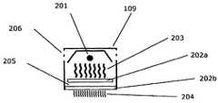
도 1은 예시적인 실시형태의 가열 시스템을 도시한다.
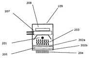
도 2는 전면에 하나의 필터 요소(도 2a), 여러 개의 필터 요소(도 2b), 냉각 요소(도 2c) 또는 확산기(diffuser)(도 2d)가 있는 소결 램프의 예시적인 실시형태를 도시한다.
도 3은 본 발명에 따른 공정의 순서를 도시한다.
도 4는 a) 폴리아미드 12와 같은 분말의 개략적인 에너지 입력 및 출력 곡선을; b) 프린트되지 않은 영역 유형의 액상 및 고상 온도를 나타내는 온도 곡선을; c) 프린트된 영역 유형의 액상 및 고상 온도를 나타내는 온도 곡선을 도시한다.
도 5는 두 가지 다른 방사기 설계를 갖는 소결 램프의 실시형태를 도시한다.
도 6는 빔 경로에 단파 적외선 방사기와 스펙트럼 변환기를 결합하여 구현된 오버헤드 방사기(overhead radiator)를 도시한다.
도 7은 방사선 스펙트럼으로서, 필터 없이 구현된(도 7a) 및 필터와 함께 구현된(도 7b) 소결 유닛에서 분말(II) 및 흡수제(I)의 흡수 범위에 대한 장파 및 단파 방사선의 중첩을 도시하며, 음영 영역은 흡수제에 의해 흡수된 방사선 에너지를 나타낸다.1 shows a heating system of an exemplary embodiment.
FIG. 2 shows an exemplary embodiment of a sintering lamp with one filter element (FIG. 2A), several filter elements (FIG. 2B), a cooling element (FIG. 2C) or a diffuser (FIG. 2D) on the front. .
3 shows the sequence of the process according to the invention.
4 shows a) a schematic energy input and output curve of a powder such as polyamide 12; b) a temperature curve representing liquid and solid temperature of the unprinted area type; c) A temperature curve showing the liquidus and solidus temperatures of the printed area type is shown.
5 shows an embodiment of a sintering lamp with two different radiator designs.
6 shows an overhead radiator implemented by combining a short-wave infrared emitter and a spectrum converter in a beam path.
FIG. 7 is the radiation spectrum, showing the superposition of long and short-wave radiation over the absorption range of powder (II) and absorbent (I) in a sintering unit implemented without a filter (FIG. 7A) and with a filter (FIG. 7B). The shaded area represents radiation energy absorbed by the absorbent.
본 발명에 따른 몇 가지 용어가 아래에 보다 상세히 설명될 것이다.Several terms according to the invention will be described in more detail below.
본 발명의 의미에서 "성형품" 또는 "부품"은 본 발명에 따른 방법 및/또는 본 발명에 따른 장치에 의해 제조되고 치수 안정성을 나타내는 3차원 물체를 의미한다."Molded article" or "part" in the sense of the present invention means a three-dimensional object manufactured by the method according to the invention and / or the device according to the invention and exhibiting dimensional stability.
"제작 공간"은 미립자 재료의 반복 코팅에 의한 제작 공정 동안 미립자 재료 층이 성장하거나 연속 원리를 적용할 때 미립자 재료 층이 통과하는 기하학적 위치이다. 제작 공간은 일반적으로 바닥, 즉 제작 플랫폼에 의해, 벽에 의해 그리고 개방된 상면, 즉 제작면에 의해 경계가 정해진다. 연속 원리에는, 일반적으로 컨베이어 벨트와 제한 측면 벽이 있다.A “production space” is a geometrical location through which a layer of particulate material passes when the layer of particulate material grows or applies a continuous principle during the manufacturing process by repeated coating of the particulate material. The production space is generally bounded by the floor, ie the production platform, by the wall and by the open top surface, ie the production surface. In the continuous principle, there are usually conveyor belts and restrictive side walls.
"가열 단계"는 공정 초기에 장치를 가열하는 것을 의미한다. 장치의 필요한 온도가 일정하게 되면 즉시 가열 단계가 완료된다."Heating step" means heating the device early in the process. As soon as the required temperature of the device is constant, the heating step is completed.
"냉각 단계"는 온도가 낮아서 제작 공간에서 부품을 제거할 때 부품이 어떤 중대한 소성 변형을 겪지 않을 때까지 적어도 지속된다.The "cooling step" lasts at least until the part is not subjected to any significant plastic deformation when the part is removed from the production space due to the low temperature.
본원에서 사용된 "미립자 재료"는 분말-기반 3D 프린팅용으로 공지된 모든 재료, 특히 중합체, 세라믹 및 금속일 수 있다. 미립자 재료는 바람직하게, 건조할 때 자유-유동성 분말이지만, 응집성의 내절단성(cut-resistant) 분말 또는 입자 하전(particle-charged) 액체일 수도 있다. 본 명세서에서, 미립자 재료와 분말은 동의어로 사용된다.As used herein, "particulate material" can be any material known for powder-based 3D printing, especially polymers, ceramics and metals. The particulate material is preferably a free-flowing powder when dried, but may also be a cohesive, cut-resistant powder or particle-charged liquid. In this specification, particulate material and powder are used synonymously.
"미립자 재료 도포"는 정해진 분말 층을 생성하는 공정이다. 이는 연속 원리로 컨베이어 벨트에 대해 제작 플랫폼 또는 경사면에서 수행될 수 있다. 미립자 재료 도포는 본원에서 "코팅" 또는 "재코팅"이라고도 한다."Particulate material application" is a process that produces a defined layer of powder. This can be done on a production platform or on a sloped surface for a conveyor belt on a continuous basis. Particulate material application is also referred to herein as “coating” or “recoating”.
본 발명의 의미에서 "선택적 액체 도포"는, 성형품에 대한 요건 및 성형품 제조의 최적화에 대한 요건에 따라서, 예를 들어 미립자 재료 도포와 관련하여 여러 번, 각각의 미립자 재료 도포 후에 또는 불규칙적으로 달성될 수 있다. 이 경우, 원하는 물품의 단면 이미지가 프린트된다."Selective liquid application" in the sense of the present invention can be achieved in accordance with the requirements for the molded article and the optimization for the manufacture of the molded article, for example several times with respect to the application of the particulate material, after each application of the particulate material or irregularly You can. In this case, a cross-sectional image of the desired article is printed.
본 발명에 따른 방법을 수행하기 위해 사용되는 "장치"는 필요한 부품을 포함하는 임의의 공지된 3D-프린팅 장치일 수 있다. 일반적인 구성요소는 코터(coater), 제작장, 연속 공정에서 제작장 또는 다른 구성요소를 이동시키기 위한 수단, 계량 장치, 및 가열 및 조사 수단, 그리고 본 기술 분야의 숙련자에게 공지되어 있고 따라서 본원에서 상세히 기술되지 않는 다른 구성요소를 포함한다.The "apparatus" used to carry out the method according to the invention can be any known 3D-printing apparatus comprising necessary parts. Common components are known to the coater, manufacturing site, means for moving the manufacturing site or other components in a continuous process, metering devices, and heating and irradiation means, and are well known to those skilled in the art and are thus described in detail herein. Other components not described.
본 발명의 의미에서 "흡수제"는 잉크젯 프린트 헤드 또는 매트릭스 같은 방식으로 작동하는 임의의 다른 장치에 의해 처리될 수 있는 매체이며, 이 매체는 분말의 국소 가열을 위한 방사선의 흡수를 향상시킨다.A "absorbent" in the sense of the present invention is a medium that can be processed by an inkjet print head or any other device operating in a matrix-like manner, which enhances the absorption of radiation for local heating of the powder.
"반사기 액체"는 선행 기술에 따라 입자 재료의 소결을 방지하기 위해 사용되는 흡수제의 길항제에 대해 사용되는 용어이다."Reflector liquid" is a term used for antagonists of absorbents used to prevent sintering of particulate materials according to the prior art.
"흡수"는 분말에 의한 방사선으로부터의 열 에너지의 흡수를 의미한다. 흡수는 분말의 유형과 방사선의 파장에 따라 다르다."Absorption" refers to the absorption of thermal energy from radiation by powder. The absorption depends on the type of powder and the wavelength of the radiation.
"지지체"는 실제 흡수제가 존재하는 매체를 의미한다. 이는 오일, 용매 또는 일반적으로 액체일 수 있다."Support" means the medium in which the actual absorbent is present. It can be an oil, a solvent or a liquid in general.
본 발명의 의미에서 "방사선"은 예를 들어 열 복사, IR 방사, 마이크로파 방사 및/또는 가시광선 또는 UV 범위의 방사선이다. 일 실시형태에서, 예를 들어 IR 방사기에 의해 생성되는 열 복사가 사용된다.“Radiation” in the sense of the present invention is, for example, thermal radiation, IR radiation, microwave radiation and / or radiation in the visible or UV range. In one embodiment, thermal radiation produced by, for example, an IR emitter is used.
본원에 사용된 "방사선-유도 가열"은 고정식 또는 이동식 방사선원에 의한 제작장의 조사를 의미한다. 흡수제는 방사선 유형에 맞게 최적화되어야 한다. 이는 "활성화" 분말과 "비활성화" 분말 간의 가열 차이를 생성하기 위한 것이다.As used herein, “radiation-induced heating” means irradiation of a manufacturing site by a stationary or mobile radiation source. The absorbent should be optimized for the type of radiation. This is to create a heating difference between the “activated” powder and the “deactivated” powder.
본원에 사용된 "IR 가열"은 구체적으로 IR 방사기에 의한 제작장의 조사를 의미한다. 방사기는 고정되거나 변위 단위만큼 제작장에서 이동할 수 있다. 흡수제를 사용함으로써, IR 가열은 제작장에서 다양한 온도 증가를 유발한다.As used herein, "IR heating" specifically refers to irradiation of the manufacturing site by an IR emitter. The emitter can be fixed or moved in the manufacturing unit by a displacement unit. By using absorbents, IR heating causes various temperature increases in the manufacturing plant.
"복사 가열"은 "IR 가열"이란 용어를 개략적으로 말한다. 임의의 파장의 방사선의 흡수는 고체 또는 액체를 가열할 수 있다.“Radiation heating” refers roughly to the term “IR heating”. Absorption of radiation of any wavelength can heat a solid or liquid.
영역 유형은 프린트되지 않은 영역과 프린트된 영역을 구별하기 위해 사용되는 표현이다.The area type is an expression used to distinguish an unprinted area from a printed area.
"IR 방사기"는 적외선 방사원이다. 일반적으로, 석영 또는 세라믹 하우징 내의 백열등 필라멘트가 방사선을 생성하기 위해 사용된다. 사용되는 재료에 따라, 방사선에 대해 다양한 파장이 발생한다. 또한, 이러한 유형의 방사기의 파장은 또한 그 전력에 따라 다르다.An "IR emitter" is an infrared radiation source. Generally, incandescent filaments in quartz or ceramic housings are used to generate radiation. Depending on the material used, various wavelengths are generated for radiation. In addition, the wavelength of this type of emitter also depends on its power.
"방사선원"는 일반적으로 특정 파장 또는 특정 파장 범위의 방사선을 방출한다. 거의 단색인 방사선을 갖는 방사선원을 "단색 방사기(monochromatic radiator)"라고 한다. 방사선원은 "방출기(emitter)"라고도 한다.A "radiation source" generally emits radiation of a specific wavelength or a specific wavelength range. A radiation source having almost monochromatic radiation is called a "monochromatic radiator." Radiation sources are also called "emitters".
본 발명의 의미에서 "오버헤드 방사기"는 제작장 위에 장착된 방사선원이다. 이는 고정식이지만, 조정 가능한 방사속(radiant power)을 갖는다. 이는 본질적으로 비-선택적 표면 가열을 보장한다."Overhead radiator" in the sense of the present invention is a radiation source mounted on the manufacturing site. It is stationary, but has adjustable radiant power. This essentially ensures non-selective surface heating.
"소결 방사기(sintering radiator)"는 프린트된 공정 분말을 이의 소결 온도 이상으로 가열하는 방사선원이다. 이는 고정식일 수 있다. 그러나, 바람직한 실시형태에서, 이는 제작장 위에서 이동한다. 본 발명의 의미에서, 소결 방사기는 단색 방사기로서 구현된다.A "sintering radiator" is a radiation source that heats a printed process powder above its sintering temperature. It can be stationary. However, in the preferred embodiment, it moves on the manufacturing floor. In the sense of the present invention, the sintered spinning machine is embodied as a single color spinning machine.
"이차 방사기"는 수동 가열에 의해 그 자체가 활성 방사선 방출기가 되는 방사기를 의미한다."Secondary radiator" means a radiator which itself becomes an active radiation emitter by passive heating.
"소결"은 분말 내 입자의 부분 융합 대한 용어이다. 이 시스템에서, 강도의 증가는 소결과 관련된다."Sintering" is a term for the partial fusion of particles in a powder. In this system, an increase in strength is associated with sintering.
"소결 창"이란 용어는 분말을 처음 가열할 때 발생하는 융점과 후속 냉각 중의 응고점 간의 온도차를 의미한다.The term "sintering window" refers to the temperature difference between the melting point that occurs when the powder is first heated and the freezing point during subsequent cooling.
"소결 온도"는 분말이 처음 융합되고 결합하기 시작하는 온도이다."Sintering temperature" is the temperature at which the powder first fuses and begins to bond.
"재결정 온도" 미만에서, 일단 용융된 분말은 다시 응고되고 많이 수축된다.Below the "recrystallization temperature", the powder once melted again solidifies and shrinks a lot.
"패킹 밀도"는 기하학적 공간을 고형물로 채우는 것을 말한다. 이는 미립자 재료 및 도포 장치의 특성에 따라 달라지며, 소결 공정에 대해 중요한 초기 파라미터이다."Packing density" refers to filling the geometric space with solids. It depends on the properties of the particulate material and the application device and is an important initial parameter for the sintering process.
"수축"이라는 용어는 물리적 공정의 결과로서 기하학적 몸체의 치수에 대한 기하학적 단축 공정을 의미한다. 예로서, 차선적으로 패킹된 분말의 소결은 초기 부피에 대해 수축을 일으키는 공정이다. 수축은 이에 지정된 방향을 가질 수 있다.The term "shrink" means a geometric shortening process for the dimensions of the geometric body as a result of the physical process. As an example, sintering the suboptimally packed powder is a process that causes shrinkage over the initial volume. The contraction can have a direction specified therein.
"변형"은 몸체가 물리적 과정에서 불균일한 수축을 겪는 경우 발생한다. 이러한 변형은 가역적이거나 비가역적일 수 있다. 변형은 종종 구성요소의 전체 형상과 관련된다."Deformation" occurs when the body undergoes uneven contraction in the physical process. These modifications can be reversible or irreversible. Deformation is often related to the overall shape of the component.
본 명세서에서 사용된 "컬링(curling)"은 기술된 발명의 층별 접근 방식으로 인한 효과를 의미한다. 이는 신속하게 연속적으로 생성되는 층들이 다른 정도의 수축을 겪게 되는 것을 의미한다. 물리적 효과로 인해, 화합물은 이후 수축 방향과 일치하지 않는 방향으로 변형된다.As used herein, "curling" refers to the effect due to the layered approach of the described invention. This means that rapidly successively produced layers undergo different degrees of contraction. Due to the physical effect, the compound is subsequently deformed in a direction that does not coincide with the contraction direction.
"그레이스케일 값(grayscale value)"은 분말에 프린트되는 활성제(activator)의 양을 의미한다. 본 발명에 따르면, 다른 정도의 가열을 달성하기 위해 다른 그레이스케일 값이 제작장 상에 프린트될 수 있다."Grayscale value" means the amount of activator printed on the powder. According to the present invention, different grayscale values can be printed on the shop floor to achieve different degrees of heating.
본 발명의 의미에서 "스펙트럼 변환기"는 방사선, 예를 들어, 전자기 열 복사를 흡수하고 하나 이상의 정해진 파장 범위를 방사하거나 방출하는 수단이고; 이 경우, 스펙트럼 변환기는 전자기 열 복사(단파 또는 장파 복사)의 방출기에 의해, 예를 들어 오버헤드 방사기 또는 소결 장치와 같은 방사기 또는 램프에 의해 조사된 후 정해진 전자기 열 복사를 방출한다.A “spectral converter” in the sense of the present invention is a means for absorbing radiation, eg electromagnetic heat radiation, and emitting or emitting one or more defined wavelength ranges; In this case, the spectral converter emits a defined electromagnetic heat radiation after being irradiated by an emitter of electromagnetic heat radiation (short or long wave radiation), for example by an emitter or lamp such as an overhead radiator or a sintering device.
본 발명의 의미에서 "필터" 또는 "필터링"은, 원하는 전자기 방사선 스펙트럼이 표적 표면, 예를 들어, 제작장 표면에 부딪히는, 전자기 방사선 스펙트럼 일부의 블랭킹(blanking)을 의미한다.By "filter" or "filtering" in the sense of the present invention is meant blanking of a portion of the electromagnetic radiation spectrum, in which the desired electromagnetic radiation spectrum strikes a target surface, for example a shop floor surface.
본 발명의 의미에서 "온도 창(temperature window)" 또는 "온도 범위"는 사용되는 미립자 재료의 소결 범위 미만 또는 소결 범위 내의 정해진 온도 범위를 의미한다.“Temperature window” or “temperature range” in the sense of the present invention means a defined temperature range within or within the sintering range of the particulate material used.
본 발명의 의미에서 "하나 이상의 파장 범위의 방사된 스펙트럼"은 스펙트럼 변환기의 방사된 스펙트럼에 해당한다.“Emitted spectrum of one or more wavelength ranges” in the sense of the present invention corresponds to the emitted spectrum of a spectrum converter.
본 발명의 의미에서 "확산기"는 입사 전자기 방사선을 예를 들어 균질하게 및/또는 균일하게 및/또는 방향에 관계없이 산란시키기 위한 수단이다."Diffuser" in the sense of the present invention is a means for scattering incident electromagnetic radiation, for example, homogeneously and / or uniformly and / or irrespective of direction.
본 발명의 의미에서 "기본 온도"는 미립자 재료가 가열되는 온도이고 용융 온도 및/또는 소결 온도보다 낮은 온도를 의미한다.“Basic temperature” in the sense of the present invention means the temperature at which the particulate material is heated and lower than the melting temperature and / or sintering temperature.
본 발명은 아래에서 더욱 상세히 기술될 것이며, 본 발명의 각각의 양태 및 특징은 각각의 특징에 대해 명시적으로 언급되지 않더라도 서로 결합될 수 있다.The invention will be described in more detail below, and each aspect and feature of the invention may be combined with each other, although not explicitly stated for each feature.
본 출원이 근거를 두는 목적은, 정해진 층 내에서 제작장 상에 미립자 제작 재료가 코터에 의해 도포되고, 하나 이상의 액체 또는 하나 이상의 흡수제의 미립자 재료가 선택적으로 도포되고, 에너지 투입이 방사기에 의해 달성되고, 선택적으로 도포된 흡수제가 있는 영역이 선택적으로 응고되고, 제작장이 하나의 층 두께만큼 하강하거나 코터가 하나의 층 두께만큼 상승하며, 원하는 3D 성형품이 생성될 때까지 이들 단계가 반복되는, 3D 성형품을 제조하는 방법에 의해 본 발명에 따라 달성되며, 방법은 적어도 하나의 스펙트럼 변환기를 사용하는 것을 특징으로 한다.The object on which this application is based is that a particulate production material is applied by a coater on a manufacturing site within a defined layer, one or more liquid or one or more absorbent particulate materials are selectively applied, and energy input is achieved by a radiator. 3D, where these areas are repeated until the area with the selectively applied absorbent is selectively solidified, the manufacturing site is lowered by one layer thickness or the coater is increased by one layer thickness, and the desired 3D molded product is produced. It is achieved according to the invention by a method for producing a molded article, the method being characterized by using at least one spectral converter.
따라서, 본 발명은 반복 공정 단계의 온도 창을 보다 정확하게 조정할 수 있는 유리한 방법을 제공한다. 결과적으로, 절차, 제품 품질, 재료의 재활용률, 생태학적 장점 및 비용 편익이 크게 향상된다.Thus, the present invention provides an advantageous way to more accurately adjust the temperature window of the repeating process step. As a result, procedures, product quality, recycling rate of materials, ecological advantages and cost benefits are greatly improved.
또한, 사용되는 기계 및 기계 내에 존재하는 구성요소에 대해 절차가 보다 온화하게 진행된다. 열 발생 또한 부분적으로 더 낮으며 어떤 경우에도 보다 정확하게 제어할 수 있다. 이는 또한 방법을 보다 에너지 효율적으로 만든다.In addition, the procedure proceeds more gently for the machine used and the components present in the machine. Heat generation is also partially lower and can be more precisely controlled in any case. This also makes the method more energy efficient.
본 발명에 따른 방법에서, 단파 또는 장파 방사선을 필터링하는 적어도 하나의 필터인 스펙트럼 변환기가 사용될 수 있다.In the method according to the invention, a spectrum converter, which is at least one filter for filtering short-wave or long-wave radiation, can be used.
또한, 본 발명에 따른 방법에서, 필터링된 방사선 범위는 사용된 미립자 재료의 스펙트럼과 호환되는 방식으로 선택될 수 있다. 이 경우, 필터는 입자 재료 상에 방사되는 스펙트럼이 바람직하게 8 내지 3.5 마이크로미터의 파장을 갖는 방식으로 선택된다. 필터 또는 필터들은 방사선의 파장이 가열 단계 및/또는 소결 단계에 대해 최적화되고 따라서 개선된 온도 창이 제작장 상의 재료 층 자체에서 달성되는 방식으로 선택될 수 있다.In addition, in the method according to the invention, the filtered radiation range can be selected in a manner compatible with the spectrum of the particulate material used. In this case, the filter is selected in such a way that the spectrum emitted on the particle material preferably has a wavelength of 8 to 3.5 micrometers. The filter or filters can be selected in such a way that the wavelength of the radiation is optimized for the heating step and / or the sintering step and thus an improved temperature window is achieved in the material layer itself on the shop floor.
공정 파라미터와 호환되는 임의의 재료가 본 발명에 따른 방법에서 사용되고 도포될 수 있다. 예를 들어, 폴리아미드 분말, 폴리아미드계 열가소성 엘라스토머 또는 우레탄계 열가소성 엘라스토머가 분말 재료서 사용될 수 있다. 따라서, 필터 및 온도 창은 이후 무엇보다도 제품 파라미터 및 재활용률에 대한 유리한 절차 및 장점을 달성하기 위해 조정될 수 있다.Any material compatible with process parameters can be used and applied in the method according to the invention. For example, polyamide powder, polyamide-based thermoplastic elastomer or urethane-based thermoplastic elastomer can be used as the powder material. Thus, the filter and temperature windows can then be adjusted to achieve advantageous procedures and advantages for product parameters and recycling rates, among other things.
예를 들어, 본 발명에 따른 방법은, 도포된 분말 층이 제 1 가열 단계에서 분말 재료의 소결 창 내에 있는 분말의 기본 온도로 흡수제 없이 가열되고, 제 2 소결 단계는 분말의 용융 온도보다 높은 소결 온도에서 흡수제로 프린트된 영역의 열 투입에 의한 선택적 응고를 유도하고, 선택적으로 도포된 흡수제가 있는 영역은 흡수제가 없는 영역보다 제 1 단계에서 더 가열되고, 따라서 흡수제가 있는 영역과 흡수제가 없는 영역 사이에 온도차가 설정되는 것을 특징으로 한다.For example, in the method according to the invention, the applied powder layer is heated in the first heating step without an absorbent to the basic temperature of the powder in the sintering window of the powder material, and the second sintering step is higher than the melting temperature of the powder Induces selective coagulation by heat input of the area printed with the absorbent at temperature, and the area with the selectively applied absorbent is heated in the first step more than the area without the absorbent, thus the area with the absorbent and the area without the absorbent It is characterized in that the temperature difference is set in between.
또한, 상기 목적은, 분말-기반 프린팅 공정에 필요한 모든 구성요소를 포함하는, 3D 성형품을 제조하기에 적합한 장치에 의해 본 발명에 따라 달성되며, 장치는 바람직하게 냉각 슬롯(cooling slot), 냉각 리세스(cooling recess), 냉각 그루브(cooling groove) 및/또는 냉각 보어(cooling bore)를 갖는 적어도 하나의 스펙트럼 변환기를 포함하는 것을 특징으로 한다.In addition, the above object is achieved according to the invention by means of a device suitable for manufacturing a 3D molded article comprising all the components necessary for a powder-based printing process, the device preferably being a cooling slot, a cooling li It is characterized by comprising at least one spectral converter having a cooling recess, a cooling groove and / or a cooling bore.
본 발명에 따른 장치는 공지된 장치 및 공정의 단점이 감소되거나 본질적으로 회피될 수 있는 유리한 방식으로 달성된다.The device according to the invention is achieved in an advantageous way in which the disadvantages of known devices and processes can be reduced or essentially avoided.
본 발명에 따른 장치를 사용하면, 온도 창을 보다 한정된 영역으로 이동시킬 수 있고 따라서 사용된 재료와 관련하여 보다 최적의 온도 범위를 달성할 수 있다. 이는 중간체 및 제품의 품질 측면에서 추가 이점을 제공한다. 또한, 분말 재료의 재활용률이 이에 따라 증가될 수 있고, 비용 절감 및 이에 따라 낮은 생산 비용을 달성할 수 있다.With the device according to the invention, the temperature window can be moved to a more confined area and thus a more optimal temperature range can be achieved with respect to the material used. This provides additional advantages in terms of the quality of the intermediates and products. In addition, the recycling rate of the powder material can be increased accordingly, and cost reduction and thus low production cost can be achieved.
본 발명에 따른 장치는, 스펙트럼 변환기가, 선택된 파장 범위를 정의하고 해당 파장 범위를 필터링하는 적어도 하나의 필터인 것을 특징으로 한다.The device according to the invention is characterized in that the spectrum converter is at least one filter that defines the selected wavelength range and filters the wavelength range.
또한, 원하는 공정 조건에 적합한 모든 스펙트럼 변환기 또는 필터가 사용될 수 있고, 예를 들어 필터는 붕규산 디스크(borosilicate disk)이다.In addition, any spectral converter or filter suitable for the desired process conditions can be used, for example the filter is a borosilicate disk.
본 발명의 일 양태에서, 선택된 파장 범위는 장파 또는 단파 적외선에서 선택되고, 바람직하게는 8 μm 내지 3.5 μm 또는 3.5 μm 내지 0.5 μm의 파장 범위인 것이 중요하다.In one aspect of the present invention, it is important that the selected wavelength range is selected from long-wave or short-wave infrared rays, and preferably is a wavelength range of 8 μm to 3.5 μm or 3.5 μm to 0.5 μm.
본 발명에 따른 장치에서, 스펙트럼 변환기는 임의의 적절한 방식으로 배열될 수 있다. 적어도 두 개의 스펙트럼 변환기는 바람직하게 적어도 두 개의 스펙트럼 변환기 사이에 공동을 갖도록 본질적으로 하나 위에 다른 하나가 있는 방식으로 배치되는 것이 유리할 수 있다.In the device according to the invention, the spectrum converter can be arranged in any suitable way. It may be advantageous that at least two spectral converters are preferably arranged in such a way that there is essentially one above the other so as to have a cavity between the at least two spectral converters.
본 발명에 따른 장치는 고속 소결 공정에 필요한 공지된 모든 부품을 갖고, 따라서 여기서 상세히 기술될 필요는 없다. 본 발명에 따른 방법에 적합한 부품은 제작 플랫폼, 측벽, 작업 상자(job box), 리코터(recoater), 프린트 헤드, 세라믹 시트, 에너지 투입 수단, 바람직하게 하나 이상의 방사기, 바람직하게 오버헤드 방사기 또는/및 소결 방사기 유닛에서 선택되는 구성요소이다.The device according to the invention has all known parts required for a high-speed sintering process, and therefore need not be described in detail here. Components suitable for the method according to the invention are fabrication platforms, side walls, work boxes, recoaters, print heads, ceramic sheets, energy input means, preferably one or more radiators, preferably overhead radiators or / And sintered radiator units.
상기한 바와 같이, 본 발명의 근본적인 양태는 공정의 파장 범위 또는 온도 창을 제어하고 한정된 영역에서 프린팅 공정을 수행하는 것이다.As described above, the fundamental aspect of the present invention is to control the wavelength range or temperature window of the process and perform the printing process in a limited area.
따라서, 오버헤드 방사기는 8 내지 3.5 μm의 파장 범위를 방사하고 및/또는 바람직하게 필터(들)를 포함하는 소결 방사기 유닛은 입자 재료 및/또는 제작 표면 상에 방사되는3.5 내지 0.5 μm의 파장 범위를 방사하는 것이 유리하다.Thus, the overhead radiator radiates a wavelength range of 8 to 3.5 μm and / or preferably a sintered radiator unit comprising filter (s) has a wavelength range of 3.5 to 0.5 μm radiated on the particle material and / or fabrication surface. It is advantageous to emit.
또한, 본 발명에 따른 장치는 유체-냉각 방사기, 팬(fan), 제작 컨테이너의 단열재, 제작 플랫폼의 단열재, 저항 히터, 가열 코일, 코터의 저항 히터, 고온계, 확산기 및 적외선 방사기로 이루어진 군에서 선택되는 하나 이상의 구성요소를 더 포함하는 것이 유리할 수 있다.In addition, the device according to the present invention is selected from the group consisting of a fluid-cooled radiator, fan, insulation of a manufacturing container, insulation of a manufacturing platform, resistance heater, heating coil, coater resistance heater, pyrometer, diffuser and infrared radiator It may be advantageous to further include one or more components to be used.
본 발명의 추가 양태가 아래에 명시될 것이다.Additional aspects of the invention will be specified below.
일반적으로, 상기 목적은, 종래의 저비용 IR 또는 건조 방사기에 해당하지만, 장파 IR 스펙트럼의 일부가 빔 경로에 삽입된 필터에 의해 분말 표면에서 멀리 떨어져 있는 소결 방사기인 방사선원을 사용함으로써 달성된다. 이들 필터는 적절한 흡수 특성을 갖는 특수 유리일 수 있다. 액체 또는 기체 층과 같은 비-고체 물질에 의해 필터링하는 것도 가능하다.In general, this object is achieved by using a radiation source that is a sintered emitter that is part of a conventional low cost IR or dry emitter, but a portion of the long wave IR spectrum is far from the powder surface by a filter inserted in the beam path. These filters can be special glass with suitable absorption properties. It is also possible to filter by non-solid materials such as liquid or gaseous layers.
전달되지 않은 흡수된 방사 에너지는 큰 노력 없이 냉각될 수 있는데, 이는 분말 표면을 냉각시키고 소결 과정을 방해하는, 분말 표면 상으로의 공기 흐름이 방지되기 때문이다. 근적외선 방사기의 튜브에 비해 더 큰 면적은 공기 냉각의 효과를 촉진하고, 이는 따라서 매우 간단하고, 기술적으로 그리고 비용 효율적으로 수행될 수 있다. 더 작은 설계의 경우, 모터 팬과 같은 전기로 작동되는 유닛 없이도 완전히 이루어질 수 있도록 대류 공기 이동을 사용하면 충분하다.The absorbed radiated energy that has not been transferred can be cooled without great effort, since air flow over the powder surface is prevented, which cools the powder surface and interferes with the sintering process. The larger area compared to the tube of the near infrared radiator promotes the effect of air cooling, which can thus be done very simply, technically and cost effectively. For smaller designs, it is sufficient to use convective air movement so that it can be achieved completely without an electrically operated unit such as a motor fan.
하나 이상의 필터를 다른 필터 뒤에 배치하는 것도 가능하다. 이는 유효 냉각 표면을 추가로 증가시킨다. 필터 특성의 동등하게 달성할 수 있는 개선은 경제적인 설계를 가능하게 한다.It is also possible to place more than one filter behind another. This further increases the effective cooling surface. Equally achievable improvement in filter properties enables economical design.
비-고체 재료를 기반으로 하는 필터는 필터 및 냉각 매체에 동일하게 대응할 수 있다.Filters based on non-solid materials can equally correspond to filters and cooling media.
장파 적외선의 제거는 다른 많은 장점을 갖는다. 예를 들어, 이는 상기 방사선에 대해 투명한 재료의 선택을 증가시킨다. 이는 방사선의 균일성을 극대화하기 위해 확산기로 사용될 수 있는 시판되는 재료를 포함한다. 이는 소결 램프의 크기 및 이에 따라 공정 챔버의 크기를 감소시킬 수 있고, 이는 공정의 더욱 간단한 온도 제어에 유리하다.Removal of long-wave infrared has many other advantages. For example, this increases the selection of materials that are transparent to the radiation. It includes commercially available materials that can be used as diffusers to maximize radiation uniformity. This can reduce the size of the sintering lamp and thus the size of the process chamber, which is advantageous for simpler temperature control of the process.
따라서, 더 높은 방사선 강도를 갖는 조명을 이용할 수 있는데, 이는 층 구축 공정에서 부분적으로 용융된 개별 표면의 결합을 증가시킨다. 이는 생성될 성형품의 강도를 향상시킨다. 상기한 방사선원을 사용하면, 방사기와 각각의 영역 사이의 거리뿐만 아니라 방사기의 크기를 줄일 수 있고, 따라서 보다 컴팩트한 기계 구조를 실현할 수 있고 에너지 효율을 크게 높일 수 있다.Thus, illumination with higher radiation intensity can be used, which increases the bonding of the partially molten individual surfaces in the layer building process. This improves the strength of the molded article to be produced. By using the above-described radiation source, it is possible to reduce the size of the radiator as well as the distance between the radiator and each region, thus realizing a more compact mechanical structure and greatly improving energy efficiency.
사용 가능한 방사기 출력은 장파 방사선의 방출과 분리되기 때문에, 장치의 출력을 문제없이 증가시킬 수 있다. 공정 자체는 사실상 영향을 받지 않는다. 이는 공정 속도를 증가시킬 수 있다.Since the usable radiator output is separate from the emission of long-wave radiation, the output of the device can be increased without problems. The process itself is virtually unaffected. This can increase process speed.
반대로, 파장과 방사기 온도의 분리는 오버헤드 유닛에 대해 사용될 수 있다.Conversely, separation of wavelength and radiator temperature can be used for the overhead unit.
단파 방사기에 의해, 빔 경로로 도입된 몸체는 평면 방식으로 가열되어 그 자체가 장파 범위에서 방사선을 방출하도록 자극될 수 있다.By means of a short-wave emitter, the body introduced into the beam path can be heated in a planar manner and itself stimulated to emit radiation in the long-wave range.
평면체가 충분히 얇고 절대 열용량이 낮게 유지되는 경우, 예를 들어, 대면적의 성형품을 프린트할 때 분말 케이크(powder cake)의 에너지 함량의 급격한 변화는 몇 시간의 경제적으로 합리적인 기간 내에 3차원 성형품을 생성하기 충분한 속도로 반응할 수 있는데, 이는 출력을 조정하여 분말 표면의 온도를 조정할 수 있도록 방사기 시간을 제공하기 위해 프린트된 각각의 층마다 정지할 필요가 없기 때문이다.When the planar body is sufficiently thin and the absolute heat capacity is kept low, for example, when printing a large-area molded article, a rapid change in the energy content of the powder cake creates a three-dimensional molded article within an economically reasonable period of several hours. The reaction can be performed at a sufficient rate, as there is no need to stop for each printed layer to provide the spinner time to adjust the power to adjust the temperature of the powder surface.
실시예Example
사용된 수단과 이들의 효과에 대한 간략한 설명Brief description of the means used and their effectiveness
각각의 유형의 영역을 특별히 가열하는 주요 목적은 방사선 필터를 갖는 단파 IR 방사기의 사용에 의해 달성된다.The main purpose of specifically heating each type of area is achieved by the use of short-wave IR emitters with radiation filters.
선행 기술의 방법은 층상화(layering), 프린팅, 방사선 노출 및 하강 단계로 구성된다. 제 1 단계는 공지된 분말-기반 3D 프린팅의 층상화와 유사하다. 분말은 블레이드 앞쪽에 배치되고, 제작 플랫폼 상에 도포되며, 블레이드에 의해 평활화된다. 이 경우, 층 두께는 두 가지 연속적인 코팅 작업에서 제작 플랫폼의 위치를 결정한다.The prior art method consists of layering, printing, radiation exposure and descending steps. The first step is similar to the layering of known powder-based 3D printing. The powder is placed in front of the blade, applied on the fabrication platform and smoothed by the blade. In this case, the layer thickness determines the location of the fabrication platform in two successive coating operations.
그 다음, 층이 프린트된다. 여기에 언급된 방법에서, 액체는 잉크젯 프린트 헤드에 의해 도포된다. 액체의 일부는 방사선에 노출될 때 분말의 국소 가열을 유발하는 흡수제이다.Then, the layer is printed. In the method mentioned herein, the liquid is applied by an inkjet print head. Part of the liquid is an absorbent that causes local heating of the powder when exposed to radiation.
이렇게 프린트된 층은 이후 방사선원에 의해 스캔되고 선택적으로 가열된다. 방사선 열원이 필터 없이 사용되면, 전체 분말이 강하게 가열된다. 그러나, 온도는 특히 입자가 소결되기 시작하도록 활성화된 영역에서 증가한다. 필터가 있는 방사기를 사용하면, 이 공정을 보다 잘 제어할 수 있으며, 각각의 유형의 영역에 대해 특별히 작용할 수 있다.The layer thus printed is then scanned by a radiation source and optionally heated. When a radiation heat source is used without a filter, the entire powder is strongly heated. However, the temperature increases, especially in the area where the particles are activated to start sintering. The use of filter emitters gives better control of this process and can act specifically for each type of area.
이 단계 후에, 제작장은 하나의 층 두께만큼 하강한다. 이후, 상기한 모든 단계는 원하는 부품이 얻어질 때까지 반복된다.After this step, the production site descends by one layer thickness. Thereafter, all the above steps are repeated until the desired part is obtained.
제작장 또는 프린트되지 않은 영역은 소결 온도 근처의 온도로 유지된다. 한편으로, 분말을 소결하기 위한 추가 에너지는 적으며 부드럽게 작용하는 수단에 의해 도입될 수 있다. 다른 한편으로, 부품 주변의 온도는 너무 높고, 따라서 온도는 제작 공정이 진행될 때 부품의 주변 영역에서도 재결정 온도 미만으로 떨어지지 않으며, 결과적으로 층상화를 방해하지 않는다.The production site or unprinted area is maintained at a temperature near the sintering temperature. On the one hand, the additional energy for sintering the powder is small and can be introduced by means of smooth action. On the other hand, the temperature around the component is too high, so the temperature does not fall below the recrystallization temperature even in the peripheral region of the component as the manufacturing process progresses, and consequently does not interfere with stratification.
제작장을 스캔하는 방사선원에 더하여, 추가의 고정식 방사선원이 선택적으로 제작장 위에 존재할 수 있다. 추가의 방사선원은 제작장이 코터 또는 프린트 헤드와 같은 유닛에 의해 덮이지 않을 때에만 작동한다. 이른바 이러한 오버헤드 방사기는 바람직하게 제작장에서 일정한 온도를 설정하도록 제어된다. 예를 들어, 실제 온도를 결정하기 위해 고온계 센서를 사용할 수 있다. 이러한 구성에서, 오버헤드 방사기는 중앙 온도 제어 구성요소를 구성한다.In addition to the radiation source that scans the workshop, additional stationary radiation sources may optionally be present on the workshop. Additional radiation sources only work when the workshop is not covered by a unit such as a coater or print head. The so-called overhead radiators are preferably controlled to set a constant temperature in the manufacturing plant. For example, a pyrometer sensor can be used to determine the actual temperature. In this configuration, the overhead radiator constitutes a central temperature control component.
오버헤드 방사기는 공정 온도를 제어하는 기능을 수행한다. 그러나, 이러한 제어는 또한 소결 방사기에 의해 달성될 수 있다. 이 경우, 프린트되지 않은 영역을 가열하는 데 적합한 방사기가 사용되어야 하며, 공정 요건에 따라 이들의 전력이 제어되어야 한다. 또한 소결 및 저-수축 제작에 필요한 프린트된 영역은 방사선으로 가열되어야 한다.The overhead radiator serves to control the process temperature. However, this control can also be achieved by a sintered spinning machine. In this case, suitable emitters must be used to heat the unprinted areas, and their power must be controlled according to process requirements. Also, the printed area required for sintering and low-shrink fabrication must be heated with radiation.
오버헤드 방사기를 통한 제어 없이도, 프린팅 및 코팅 공정은 사실상 지연 없이 순차적으로 수행될 수 있다.Even without control through an overhead radiator, the printing and coating process can be performed sequentially with virtually no delay.
이 방법은 또한 오버헤드 방사기와 소결 방사기의 기능을 결합한 고정식 방사선 패널이 구현될 수 있게 한다. 방사선 강도의 기하학적 움직임이 기하학적으로 의미가 있는 경우, 상기 방사기는 전환 가능한 섹션들로 조립될 수 있다. 예를 들어, 이동 중에 프린트 헤드와 같은 민감한 구성요소를 보호하기 위해, 예를 들어, 일부 섹션에서 방사기의 작동이 정지될 수 있다.This method also allows a fixed radiation panel to be implemented that combines the functions of an overhead radiator and a sintered radiator. If the geometrical motion of the radiation intensity is geometrically meaningful, the emitter can be assembled into switchable sections. For example, in order to protect sensitive components, such as a print head, during movement, for example, the operation of the emitter can be stopped in some sections.
폐쇄형 유닛의 현재의 비용-효율적인 구성에 의해 제공되는 장파 적외선 방사로부터의 차폐 및 향상된 냉각은 장치의 온도를 낮춘다. 이는 민감한 구성요소를 보호하는 데 유리하다.Shielding from long-wave infrared radiation and improved cooling provided by the current cost-effective construction of the closed unit lowers the temperature of the device. This is advantageous for protecting sensitive components.
본 발명의 추가의 예시적인 실시형태Further exemplary embodiments of the invention
장치에 대한 일반적인 자세한 설명General detailed description of the device
본 발명을 실시하기 위해 필요한 장치는 분말-기반 프린팅용 3D 프린터를 기반으로 한다. 또한, 공정 액체의 온도 제어 및 인쇄를 위해 추가의 공정 유닛이 사용된다.The apparatus needed to practice the present invention is based on a 3D printer for powder-based printing. In addition, additional process units are used for temperature control and printing of process liquids.
공정의 초반에, 전체 장치가 가열된다. 이를 위해, 모든 가열 요소가 사용되어 온도를 높인다. 시스템의 모든 측정 위치에서 온도가 일정하게 유지되는 즉시 가열 단계가 완료된다.At the beginning of the process, the entire device is heated. For this, all heating elements are used to raise the temperature. The heating step is completed as soon as the temperature remains constant at all measurement locations in the system.
본 발명의 바람직한 실시형태의 개별 가열 시스템이 도 1에 따라 아래에서 기술될 것이다.The individual heating system of the preferred embodiment of the invention will be described below according to FIG. 1.
미립자 재료를 공정 중에 위에서 증착하고 층(107)의 층 두께를 조정하는 제작 플랫폼(102)은 다양한 시스템에 의해 가열될 수 있다. 바람직한 실시형태는 전기 저항 히터(104)를 사용한다. 또한, 후자는 균일한 가열 효과를 고려하여 평면 가열 필름으로서 제공되는 것이 바람직하다. 이러한 가열 효과는 센서에 의해 인식되고 제어된다. 센서는 제작 플랫폼에 직접 연결된다. 편리하게, 제작 플랫폼 자체는 금속, 바람직하게는 알루미늄으로 제조된다. 단열재(106)는 제작 플랫폼(102)을 아래쪽에서 덮는다.The
제작 플랫폼은 또한 유체에 의해 가열될 수 있다. 이를 위해, 바람직하게 금속 제작 플랫폼 아래에 가열 코일(104)이 설치된다. 더 아래에는 가열 효과를 균질화하기 위해 단열재(106)가 배치된다.The fabrication platform can also be heated by fluid. To this end, a
예를 들어, 열전달 오일이 가열 코일을 통해 흐른다. 오일 온도를 미리 선택하면, 정확한 온도 조정이 가능하다. 충분히 높은 유량을 보장하고 전력을 조정함으로써 매우 높은 품질의 온도 제어가 달성될 수 있다.For example, heat transfer oil flows through a heating coil. If the oil temperature is selected in advance, accurate temperature adjustment is possible. Very high quality temperature control can be achieved by ensuring a sufficiently high flow rate and adjusting the power.
제작 플랫폼(102)은 이른바 제작 컨테이너(110) 내에서 이동한다. 장치의 설계에 따라, 컨테이너는 장치에서 분리될 수 있다. 이러한 방식으로, 부품을 꺼내는 동안 제 2 제작 컨테이너가 장치에서 사용될 수 있기 때문에, 큰 시간적 기계 효율이 달성될 수 있다.The
제작 컨테이너(110)도 가열된다. 제작 플랫폼에 대해서도 동일한 기술이 사용될 수 있다. 컨테이너 자체는 바람직하게 금속, 바람직하게 알루미늄으로 제조되어 양호한 열전도를 보장한다. 실제 능동적 가열(104)은 다시 단열재(105)에 의해 지지된다. 이를 통해, 효과를 향상시키면서 균일성을 높일 수 있다.The
바람직하게 전원 연결을 위해 장치와 제작 컨테이너 사이에 플러그-인(plug-in) 시스템이 배치된다. 이는 전기 연결부 또는 액체용 커넥터를 포함할 수 있다.A plug-in system is preferably arranged between the device and the manufacturing container for power connection. It can include electrical connections or connectors for liquids.
본 발명에 따른 장치의 그 다음 필수 가열 시스템은 오버헤드 방사기(108)이다. 본 발명에 따르면, 오버헤드 방사기(108)는 바람직하게 제작장 위에 배치되고 제작장을 수직으로 조사한다. 특정 각도로 제작장을 조사하는 측면 장착 방사기가 또한 바람직하다. 이러한 구성은 코터 또는 프린트 헤드의 차폐 효과를 최소화하기 위해 바람직하다.The next essential heating system of the device according to the invention is the
본 발명에 따르면, 오버헤드 방사기(108)는 최소한의 선택성을 가져야 하는 열 방사기를 구비할 수 있다. 예를 들어, 매우 큰 파장을 갖는 세라믹 방사기가 사용될 수 있다. 이른바 중파 석영-텅스텐 방사기의 사용을 또한 고려할 수 있다. 다양한 유형의 영역의 특수 가열은 이후 소결 방사기(109)에 의해 달성된다.According to the present invention, the
방법은 오버헤드 방사기(108)를 제어된 방식으로 작동시키는 것이 바람직하다. 이를 위해, 센서로서 고온계(112)를 사용하는 것이 바람직할 수 있다. 고온계는 제작장의 주변 영역 쪽으로 지향되고, 제어 시스템은 이 영역이 흡수제로 프린트된 영역이 아닌지 확인한다.It is preferred that the method operates the
본 발명의 바람직한 실시형태에서, 실제 소결은 코터와 함께 운반되는 소결 방사기(109)에 의해 수행된다. 상기 방사기는 제작장을 지나갈 때 이를 가열한다. 방사기는 새롭게 프린트된 분말 또는 이미 덮인 분말 층을 가열하기 위해 사용될 수 있다. 본 발명에 따라 그리고 도 2a에 도시된 바와 같이, 상류 필터(202)를 갖는 단파 방사선원(201)이 여기에 사용되며, 이는 본 발명에 따른 옵션으로서 여러 개의 필터를 가질 수도 있다. 도 2b에 도시된 바와 같이, 필터의 냉각을 보장하기 위해 이격된(205) 여러 개의 필터(202)가 중첩된 설계가 바람직하다.In a preferred embodiment of the invention, the actual sintering is performed by a
장치의 바람직한 실시형태에서, 분말은 층의 과도한 냉각을 방지하기 위해 이미 존재하는 분말 표면 상에 도포되기 전에 예열된다. 코터(101) 내의 전기 저항 히터(111)는 또한 분말을 예열하기에 적합하다.In a preferred embodiment of the device, the powder is preheated before being applied onto the already existing powder surface to prevent excessive cooling of the layer. The
원칙적으로, 접촉 히터로 가열된 모든 유닛은 적외선에 의해 간접적으로 가열될 수도 있다. 사용된 분말로 인해 장치에 강력한 진동이 필요한 경우, 방사선으로 코터를 가열하는 것이 특히 유리할 수 있다.In principle, all units heated with a contact heater may be indirectly heated by infrared rays. If the device requires strong vibration due to the powder used, it may be particularly advantageous to heat the coater with radiation.
바람직하게, 다음의 연속적인 공정 단계는 가열 단계 후에 장치에 의해 수행된다: 분말 층이 제작 플랫폼 상의 코터(101)에 의해 형성된다(도 3a). 선택적으로, 기계의 설계에 따라, 새로운 층이 소결 방사기(109)에 의해 추가로 가열될 수 있다. 그 다음, 이 층은 하나(100) 또는 여러 개의 잉크젯 프린트 헤드(100)에 의해 프린트된다(도 3b). 이제, 프린트된 층은 소결 램프(109)에 의해 가열되고 이후 분말로 다시 덮인다(도 3c). 그리고 나서, 제작 플랫폼(102)이 하강한다(도 3d).Preferably, the next successive process step is performed by the device after the heating step: a powder layer is formed by the
이 작업은 제작 컨테이너(110) 내에서 부품(103)이 완성될 때까지 반복된다. 그리고 나서, 냉각 단계가 이어진다. 이 단계는 바람직하게 제작 컨테이너 내에서 발생하고, 여기에는 이후 장치 외부에서 에너지가 공급된다.This operation is repeated until the
도 4는 온도 다이어그램을 도시하고 있다. 도 4a는 분말이 한 번의 사이클로 가열되고 다시 냉각될 때 분말에 의해 방출된 에너지의 프로파일을 개략적으로 도시하고 있다. 가열하는 동안 특정 온도에서 상당한 에너지 흡수가 발생한다. 이는 재료의 용융 또는 소결이 발생하는 온도(소결 온도)이다. 레이저 소결에 적합한 폴리아미드 12의 경우, 이 온도는 대략 185℃이다. 냉각하는 동안, 소결 온도(재결정 온도) 상당히 아래에 중요한 지점이 또한 존재한다. 이는 용융된 재료가 응고되는 지점이다.4 shows a temperature diagram. 4A schematically shows the profile of the energy released by the powder when it is heated in one cycle and cooled again. Significant energy absorption occurs at certain temperatures during heating. This is the temperature at which melting or sintering of the material occurs (sintering temperature). For polyamide 12 suitable for laser sintering, this temperature is approximately 185 ° C. During cooling, important points also exist significantly below the sintering temperature (recrystallization temperature). This is the point at which the molten material solidifies.
도 4b 및 도 4c는 선행 기술의 방법에 따른 공정 실행 동안의 온도 프로파일을 도시하고 있다. 도 4b는 프린트되지 않은 영역에서의 온도 프로파일을 도시하고 있다. 소결 방사선원을 사용하면, 이와는 다른 일정한 프로파일의 가열 및 냉각 단계가 생성된다. 프린트되지 않은 영역에서, 온도는 결코 소결 온도에 도달하지 못한다.4B and 4C show the temperature profile during process execution according to the prior art method. 4B shows the temperature profile in the unprinted area. The use of a sintered radiation source creates heating and cooling steps of different constant profile. In the unprinted area, the temperature never reaches the sintering temperature.
도 4c는 프린트된 영역에서의 프로파일을 도시하고 있다. 여기서, 변형이 더 크게 표시되어 있다. 공정은 적어도, 소결 온도가 잠시 초과되어 분말의 일부가 용융되고 용융 상태로 유지되도록 제어된다. 과도한 가열은 모든 분말이 이 영역에서 용융되게 하고, 따라서 심각한 휨을 초래할 수 있다. 프린트된 영역의 과도한 냉각도 피해야 하는데, 그렇지 않으면 재결정이 시작되고, 그러면 이제 가능한 전력 전달로 인한 모든 수축은 기하학적 왜곡(휨 또는 컬링)을 초래하고, 이는 추가 공정을 불가능하게 할 수 있기 때문이다.4C shows the profile in the printed area. Here, the deformation is marked larger. The process is controlled such that at least the sintering temperature is briefly exceeded so that a portion of the powder melts and remains molten. Excessive heating causes all powders to melt in this area, and thus can lead to severe warpage. Excessive cooling of the printed area should also be avoided, otherwise recrystallization will begin, and now all shrinkage due to possible power transfer will result in geometric distortion (bending or curling), which may make further processing impossible.
용융 온도와 재결정 온도 사이에서 이러한 "공정 창(process window)" 내에 정확하게 머무르는 것은 부품의 품질에 결정적이다. 이와 관련하여, 프린트된 영역 및 프린트되지 않은 영역에 서로 다른 경계 조건이 적용된다. 필터링된 단파 IR 방사원을 사용하면, 두 온도 사이의 온도 제어를 상당히 용이하게 한다.Accurately staying within this “process window” between the melting temperature and the recrystallization temperature is critical to the quality of the part. In this regard, different boundary conditions apply to the printed and non-printed areas. Using a filtered short-wave IR radiation source significantly facilitates temperature control between the two temperatures.
특히, 예시적인 실시형태는 상기한 공정에서 이들 방사선원의 장점을 사용하는 방법을 설명한다.In particular, exemplary embodiments describe how to use the advantages of these radiation sources in the above-described process.
추가의 예시적인 실시형태:Additional exemplary embodiments :
실시예 1: 방사선 필터를 갖는 단파 IR 방사기를 포함하는 소결 램프 및 열 오버헤드 램프를 포함하는 장치Example 1: Device comprising a thermal overhead lamp and a sintering lamp comprising a short-wave IR emitter with a radiation filter
도 3a에 따르면, 제작 공정 또는 공정 사이클은 제작 플랫폼 상에, 예를 들어, 100 μm의 층 두께를 갖는 하나의 분말 층의 코팅으로 시작된다. 코터(101) 또는 프린트 헤드(100)에 의해 광학적으로 마스킹되지 않는 한, 분말은 코터(101)에 의해 수행되는 코팅 공정 동안 이미 오버헤드 방사기(108)에 의해 가열된다. PA12, 이 경우 제조업체 EOS의 PA2200를 사용하는 경우, 분말은 168℃로 가열된다. 프린트된 영역의 양호한 가열을 유발하는 방사선만을 제공하는 소결 방사기(109)는 이 단계에서 작동하지 않는다.According to FIG. 3A, the manufacturing process or process cycle begins with a coating of one powder layer on the manufacturing platform, for example with a layer thickness of 100 μm. Unless optically masked by the
오버헤드 방사기(108)는 제작장의 표면 온도를 제어하도록 설계된 측정 장치를 포함한다. 이상적으로, 측정 장치는 비접촉 방식으로 온도를 결정할 수 있는 소형 고온계(112)로 구현된다. 제어장치는 측정 장치가 프린트 헤드(100)와 코터(101)에 의해 매번 마스킹된다는 사실을 감안해야 한다. 이는 측정 기능을 비활성화하거나 불감성 제어 루프 파라미터를 사용하여 이루어질 수 있다.The
제 2 단계에서, 방사선원의 파장에 맞게 정확하게 조정된 프린트 헤드(100)에 의해 흡수제, 예를 들어, 카본 블랙이 도포된다. 프린트 헤드(100)에 의해 미립자 재료 상에 적용된 이미지는 현재 성형품의 단면에 해당한다.In the second step, an absorbent, for example carbon black, is applied by the
제 3 단계는 소결 통과이다. 이를 위해, 소결 방사기 유닛(109)의 방사선원이 작동되고 제작장을 통과한다. 방사선원의 전력과 그 속도는 제작장 상의 방사 전력을 결정한다. 선행 기술과는 달리, 예를 들어, 제조업체 GVB GmbH에서 2 mm의 두께의 붕규산 유리로 제조된 방사선 필터를 갖는 소결 방사기(109)는 이러한 통과 동안 프린트되지 않은 부분을 가열하지 않는다. 따라서, 프린트되지 않은 영역은 영향을 받지 않으면서 프린트된 영역의 온도가 상승한다. 흑체(black body)의 파장 분포에 근접하고 1.2 μm의 피크 파장을 갖는 방사선원에 의해 방출된 방사선의 장파 부분은 3 μm의 파장으로부터 방사선 필터에 의해 흡수된다.The third step is through sintering. To this end, the radiation source of the
제 4 단계는 하나의 분말 층(107)의 두께만큼 제작 플랫폼(102)이 하강하는 단계이다. 이 공정 동안, 제작장은 오버헤드 방사기(108)에 개방되어, 온도 재조정이 가능하다. 이후, 공정 사이클은 코팅 공정과 함께 다시 시작된다.The fourth step is a step in which the
도 1은 실시예에서 언급한 공정을 구현하기 위한 장치를 도시하고 있다. 오버헤드 방사기(108)는 장파 내지 중파 방사선 열원으로서 구현된다. 제작 컨테이너 바닥 및 제작 플랫폼의 온도는 저항 히터(104)에 의해 제어된다. 일례로서의 장치에서, 코터(101)와 소결 방사기 유닛(109)은 연결된다. 이 유닛과 프린트 헤드(100)는 제작장 위로 별도로 이동할 수 있지만, 반드시 그럴 필요는 없다.1 shows an apparatus for implementing the process mentioned in the Examples. The
소결 방사기(109)는 도 2a에 도시 된 바와 같이 단파 방사기(201) 및 상류 필터(202)를 구비한다. 단파 방출기에 의해 생성된 장파 성분(203)은 필터에 의해 흡수되고, 따라서 단파 성분만이 분말 표면(204)에 도달 할 수 있다.The
실시예 2: 냉각 기능을 구비하는 소결 램프 장치Example 2: Sintering lamp device with cooling function
도 2b 및 도 2c는 통합된 냉각 기능을 갖는 소결 램프의 실시형태를 도시하고 있다. 방사선 필터는 예로서 두 개(202a, 202b)가 개략적으로 도시되어 있다. 두 개의 요소는 접촉하지 않지만, 이들 사이에 일정한 거리(205)를 갖고 배치된다. 이러한 설계에서, 생성된 대부분의 장파 적외선은 단파 방사기(201)에 가장 근접한 필터(202a)에 의해 흡수된다. 후자는 장파 적외선에 의해 가열되지만, 단파 방사선이 이를 통과할 수 있게 한다. 따라서, 도 1에 따른 입자 표면을 향하는 제 2 필터(202b)는 이러한 장파 열 복사에 의해 가열되지 않는다. 제 2 필터는 또한 단파 방사선이 영향을 받지 않도록 하고, 따라서 이는 프린트 헤드(100)에 의해 습윤된 입자 재료의 영역을 이의 용융 온도보다 높은 온도로 가열하기 위해 사용될 수 있다. 제 2 필터의 훨씬 낮은 온도는 이제 코팅 공정(도 3a)에 의해 소용돌이치는 입자 재료가 용융되어 필터 표면에 달라붙음으로써 방사선 흐름을 막는 것을 방지한다.2B and 2C show an embodiment of a sintering lamp with integrated cooling function. In the radiation filter, two 202a, 202b are schematically shown as examples. The two elements are not in contact, but are arranged with a
제 1 필터(202a)는 유닛(206)의 하우징의 개구에 의해 대류적으로(도 2b) 또는 냉각 유닛(도 2c)에 의해 냉각될 수 있다(도 2b). 냉각 장치를 갖는 설계는 더 큰 설계의 소결 램프에 적합하다. 이 경우, 207은 냉각 요소를 나타내고, 이를 통해 냉각 유체, 바람직하게 물이 흐른다. 냉각 요소 상에 배치된 팬(208)은 유닛 내에서 대류를 제공한다. 이 실시형태에서, 제 1 필터(202a)는 유닛의 하우징 벽에서 종료한다.The
실시예 3: 냉각 기능 및 확산기를 구비하는 소결 램프 장치Example 3: Sintering lamp device with cooling function and diffuser
도 2d에 나타낸 바와 같이, 확산기(202c)로서 실시예 2에 기술된 필터(202b)의 설계는 소결 램프가 그(204b) 위를 통과할 때 제작 플랫폼 상의 미립자 재료의 전체 표면을 균일하게 조사하는 데 그 의미가 있다. 이는 생성될 성형품의 충분히 높은 강도가 제작 플랫폼의 모서리 영역에서 또한 달성될 수 있게 한다. 이 실시예에서, 제조업체 Edmund Optics의 백색 오팔 유리인 빙정석 유리(cryolite glass)가 확산기로 적합하다.As shown in FIG. 2D, the design of the
실시예 4: 각각 방사 필터가 있고 없는 두 개의 단파 방사기를 구비하는 소결 램프 장치Example 4: Sintering lamp apparatus with two short-wave emitters each with and without a radiation filter
도 5에 따르면, 제작 공정 또는 공정 사이클은 제작 플랫폼(102) 상에 하나의 분말 층의 코팅으로 시작된다. 프린트되지 않은 영역의 양호한 가열을 야기하는 방사선을 또한 제공하는, 유닛(109)의 필터가 없는 소결 방사기(501)가 이 단계에서 작동되고, 용융 온도 미만이지만 분말의 재결정 온도보다 높은 기본 온도로 분말을 가열한다. 이를 위한 에너지 공급은 전력 및 이송 속도에 의해 제어된다. 유리하게, 생성된 온도는 측정되고 조정된다.According to FIG. 5, the manufacturing process or process cycle begins with a coating of one powder layer on the
제 2 단계에서, 흡수제가 도포되며, 이 흡수제는, 필터를 통과할 수 있는, 프린트된 영역에 대한 방사선원(502)의 파장에 대해 정확하게 조정된다. 프린트 헤드(100)에 의해 분말 상에 적용된 이미지는 현재 성형품의 단면에 해당한다.In a second step, an absorbent is applied, which is precisely adjusted for the wavelength of the
제 3 단계는 소결 통과이다. 이를 위해, 소결 유닛(109)이 작동되고 제작장을 통과한다. 방사선원의 전력과 그 속도는 분말 층 상의 방사 전력을 결정한다. 선행 기술과 달리, 두 개의 스펙트럼(501,502)을 갖는 유닛은 이러한 통과 동안 프린트되지 않은 영역과 프린트된 영역에 특히 영향을 줄 수 있다. 따라서, 프린트된 영역의 온도가 증가하면서, 프린트되지 않은 영역에서의 방사선에 의한 에너지 손실이 보상될 수 있다.The third step is through sintering. To this end, the
제 4 단계는 하나의 층 두께만큼 제작 플랫폼(102)이 하강하는 단계이며, 이러한 예시적인 공정에서 매우 짧게 유지된다. 여기에는 조정이 없으며, 임의의 지연은 열 복사에 의한 에너지 손실로 이어진다. 따라서 이 단계는 도면에 도시하지 않았다.The fourth step is the step in which the
공정 사이클이 충분히 빠르게 실행되면 오버헤드 방사기는 없어도 된다.If the process cycle runs fast enough, there is no need for an overhead emitter.
실시예 5: 단파 방사기 및 흡수제 표면을 구비하는 오버헤드 램프의 장치Example 5: Device of overhead lamp with shortwave emitter and absorber surface
도 6에 따르면, 오버헤드 램프(108)는 약 1.2 μm(601)의 피크 파장을 갖는 단파 방사기를 사용하여 설계되며, 이는 IR 방출기와 분말 표면 사이의 빔 경로(602)에 위치하는 흡수제(603)의 표면을 가열한다. 흡수제(603) 그 자체는 적외선(604)을 방출하지만, 실질적으로 더 긴 파장 스펙트럼, 바람직하게는 약 4 μm의 피크 파장을 갖는다. 흡수제는 재료의 열용량을 작게 유지하고 따라서 방출되는 장파 방사선의 반응 시간을 최소화하기 위해 가능한 한 수 밀리미터 두께로 얇게 설계된다. 제조업체 Ceramtec의 질화알루미늄으로 제조된 비산화물 세라믹인 Alunite이 바람직한데, 이는 대략 200 W/mK의 높은 열전도율을 갖고 따라서 제작하는 동안 반응 시간이 빠르기 때문이다.According to Figure 6, the
100: 프린트 헤드
101: 코터
102: 제작 플랫폼
103: arts 부품
107: 층
108: 오버헤드 방사기
109: 소결 방사기 유닛
110: 제작 컨테이너
105: 제작 컨테이너의 단열재
104: 저항 히터 또는 가열 코일
106: 제작 플랫폼의 하향 단열재
111: 저항 히터 또는 코터
112: 고온계
201: 단파 IR 방사기
202: 필터
202a: 단파 적외선 방사기 바로 옆의 필터
202b: 제작 표면 바로 옆의 필터
202c: 확산기
203: 장파 성분을 갖는 적외선
204: 장파 성분이 없는 적외선
204b: 지향되지 않은, 장파 성분이 없는 적외선
205: 두 개의 방사선 필터 사이의 공동
206: 냉각 슬롯
207: 유체-냉각 방사기
208: 팬
501: 방사선 필터가 없는 소결 방사기
502: 방사선 필터로 구현된 소결 방사기
601: 단파 적외선 방사기
602: 광대역 적외선
603: 흡수제
604: 흡수제에 의해 방출된 장파 적외선
701: 2차 피크를 갖는 종래의 방사기의 전형적인 방사선 스펙트럼
702: 저전력에서 종래의 방사기의 스펙트럼
703: 붕규산 유리 디스크의 흡수 스펙트럼
704: 고전력에서 종래의 방사기의 방출된 스펙트럼
705: 투과된 스펙트럼
706: 차단된 파장 범위100: print head
101: coater
102: production platform
103: arts part
107: floor
108: overhead radiator
109: sintered radiator unit
110: production container
105: Production container insulation
104: resistance heater or heating coil
106: downward insulation of the production platform
111: resistance heater or coater
112: pyrometer
201: short-wave IR emitter
202: filter
202a: filter right next to the shortwave infrared emitter
202b: Filter right next to the build surface
202c: diffuser
203: infrared with long wave component
204: long wavelength component-free infrared
204b: undirected, long wave-free infrared
205: cavity between two radiation filters
206: cooling slot
207: fluid-cooled radiator
208: fan
501: sintered radiator without radiation filter
502: a sintered radiator embodied in a radiation filter
601: short-wave infrared emitter
602: broadband infrared
603: absorbent
604: long-wave infrared emitted by the absorbent
701: typical radiation spectrum of a conventional emitter with a secondary peak
702: spectrum of a conventional radiator at low power
703: absorption spectrum of the borosilicate glass disk
704: Emitted spectrum of a conventional emitter at high power
705: transmitted spectrum
706: blocked wavelength range
Claims (10)
Translated fromKoreanParticulate material is applied by a coater on a fabrication site within a defined layer, particulate material of one or more liquids or one or more absorbents is selectively applied, energy input is achieved by a radiator, and there is an absorbent selectively applied A method of manufacturing a 3D molded article, wherein the regions are selectively solidified, the fabrication site is lowered by one layer thickness or the coater is raised by one layer thickness, and these steps are repeated until a desired 3D molded article is produced. Method for manufacturing a 3D molded article, characterized in that using at least one spectral converter.
스펙트럼 변환기는 단파 또는 장파 방사선을 필터링하는 적어도 하나의 필터인 것을 특징으로 하는 3D 성형품을 제조하는 방법.
According to claim 1,
A method for manufacturing a 3D molded article, characterized in that the spectrum converter is at least one filter that filters short-wave or long-wave radiation.
필터링된 방사선 범위는 사용된 미립자 재료의 스펙트럼과 호환되는 방식으로 선택되고, 미립자 재료 상에 방사되는 스펙트럼은 바람직하게 8 내지 3.5 μm의 파장을 갖고, 바람직하게,
폴리아미드 분말, 폴리아미드계 열가소성 엘라스토머 또는 우레탄계 열가소성 엘라스토머가 분말 재료서 사용되는 것을 특징으로 하는 3D 성형품을 제조하는 방법.
The method of claim 1 or 2,
The filtered radiation range is selected in a manner compatible with the spectrum of the particulate material used, and the spectrum radiated on the particulate material preferably has a wavelength of 8 to 3.5 μm, preferably,
A method for producing a 3D molded article, characterized in that polyamide powder, polyamide-based thermoplastic elastomer or urethane-based thermoplastic elastomer is used as a powder material.
도포된 분말 층이 제 1 가열 단계에서 분말 재료의 소결 창 내에 있는 분말의 기본 온도로 흡수제 없이 가열되고, 제 2 소결 단계는 분말의 용융 온도보다 높은 소결 온도에서 흡수제로 프린트된 영역의 열 투입에 의한 선택적 응고를 유도하고, 선택적으로 도포된 흡수제가 있는 영역은 흡수제가 없는 영역보다 제 1 단계에서 더 가열되고, 따라서 흡수제가 있는 영역과 흡수제가 없는 영역 사이에 온도차가 설정되는 것을 특징으로 하는 3D 성형품을 제조하는 방법.
The method according to claim 1, 2 or 3,
The applied powder layer is heated in the first heating step without an absorbent to the basic temperature of the powder in the sintered window of the powder material, and the second sintering step is applied to heat input of the area printed with the absorbent at a sintering temperature higher than the melting temperature of the powder. 3D characterized by inducing selective coagulation by, and the area with the selectively applied absorbent is heated in the first step more than the area without the absorbent, and thus a temperature difference is established between the area with the absorbent and the area without the absorbent. Method for manufacturing molded article.
An apparatus for manufacturing a 3D molded article comprising all components necessary for a powder-based printing process, the apparatus preferably comprising at least one spectral converter with cooling slots, cooling recesses, cooling grooves and / or cooling bores Device for manufacturing a 3D molded article, characterized in that.
스펙트럼 변환기는, 선택된 파장 범위를 정의하고 해당 파장 범위를 필터링하는 적어도 하나의 필터이고, 바람직하게,
필터는 붕규산 디스크인 것을 특징으로 하는 3D 성형품을 제조하는 장치.
The method of claim 5,
The spectrum converter is at least one filter that defines a selected wavelength range and filters the wavelength range, preferably,
The filter is a device for manufacturing a 3D molded article characterized in that it is a borosilicate disc.
선택된 파장 범위는 장파 또는 단파 적외선에서 선택되고, 바람직하게는 8 μm 내지 3.5 μm 또는 3.5 μm 내지 0.5 μm의 파장 범위이고, 바람직하게,
적어도 두 개의 스펙트럼 변환기는 본질적으로 하나 위에 다른 하나가 있는 방식으로 배치되고, 바람직하게 적어도 두 개의 스펙트럼 변환기 사이에 공동이 존재하는 것을 특징으로 하는 3D 성형품을 제조하는 장치.
The method of claim 5 or 6,
The selected wavelength range is selected from long-wave or short-wave infrared rays, and preferably is a wavelength range of 8 μm to 3.5 μm or 3.5 μm to 0.5 μm, preferably,
At least two spectral transducers are arranged in such a way that there is essentially one on top of the other, preferably a device for producing a 3D molded article, characterized in that a cavity exists between the at least two spectral transducers.
구성요소는 제작 플랫폼, 측벽, 작업 상자, 리코터, 프린트 헤드, 세라믹 시트, 에너지 투입 수단, 바람직하게 하나 이상의 방사기, 바람직하게 오버헤드 방사기 또는/및 소결 방사기 유닛에서 선택되는 것을 특징으로 하는 3D 성형품을 제조하는 장치.
The method according to any one of claims 5 to 7,
The component is a 3D molded article characterized in that it is selected from a production platform, sidewall, work box, recoater, print head, ceramic sheet, energy input means, preferably one or more radiators, preferably overhead radiators or / and sintered radiator units. Device for manufacturing.
오버헤드 방사기는 8 내지 3.5 μm의 파장 범위를 방사하고 및/또는 바람직하게 필터(들)를 포함하는 소결 방사기 유닛은 입자 재료 및/또는 제작 표면 상에 방사되는 3.5 내지 0.5 μm의 파장 범위를 방사하는 것을 특징으로 하는 3D 성형품을 제조하는 장치.
The method according to any one of claims 5 to 8,
The overhead emitter emits a wavelength range of 8 to 3.5 μm and / or preferably a sintered emitter unit comprising filter (s) emits a wavelength range of 3.5 to 0.5 μm that is emitted on the particle material and / or fabrication surface. Device for manufacturing a 3D molded article, characterized in that.
유체-냉각 방사기, 팬, 제작 컨테이너의 단열재, 제작 플랫폼의 단열재, 저항 히터, 가열 코일, 코터의 저항 히터, 고온계, 확산기 및 적외선 방사기로 이루어진 군에서 선택되는 하나 이상의 구성요소를 더 포함하는 것을 특징으로 하는 3D 성형품을 제조하는 장치.
The method according to any one of claims 5 to 9,
It further comprises one or more components selected from the group consisting of fluid-cooled radiators, fans, insulation of production containers, insulation of production platforms, resistance heaters, heating coils, resistance heaters of coaters, pyrometers, diffusers and infrared emitters. Apparatus for manufacturing 3D molded articles made with
Applications Claiming Priority (3)
| Application Number | Priority Date | Filing Date | Title |
|---|---|---|---|
| DE102017006860.7 | 2017-07-21 | ||
| DE102017006860.7ADE102017006860A1 (en) | 2017-07-21 | 2017-07-21 | Method and device for producing 3D molded parts with spectrum converter |
| PCT/DE2018/000205WO2019015707A1 (en) | 2017-07-21 | 2018-07-09 | METHOD AND DEVICE FOR PRODUCING 3D SHAPES WITH SPECTRUM TRANSFORMERS |
Publications (2)
| Publication Number | Publication Date |
|---|---|
| KR20200031105Atrue KR20200031105A (en) | 2020-03-23 |
| KR102615544B1 KR102615544B1 (en) | 2023-12-19 |
Family
ID=63259348
Family Applications (1)
| Application Number | Title | Priority Date | Filing Date |
|---|---|---|---|
| KR1020207001896AActiveKR102615544B1 (en) | 2017-07-21 | 2018-07-09 | Method and apparatus for manufacturing 3D molded parts using spectral converters |
Country Status (7)
| Country | Link |
|---|---|
| US (3) | US11279087B2 (en) |
| EP (1) | EP3655234A1 (en) |
| JP (1) | JP2020527491A (en) |
| KR (1) | KR102615544B1 (en) |
| CN (1) | CN110944824B (en) |
| DE (1) | DE102017006860A1 (en) |
| WO (1) | WO2019015707A1 (en) |
Families Citing this family (23)
| Publication number | Priority date | Publication date | Assignee | Title |
|---|---|---|---|---|
| DE102012010272A1 (en) | 2012-05-25 | 2013-11-28 | Voxeljet Technology Gmbh | Method for producing three-dimensional models with special construction platforms and drive systems |
| DE102013018182A1 (en) | 2013-10-30 | 2015-04-30 | Voxeljet Ag | Method and device for producing three-dimensional models with binder system |
| DE102015006533A1 (en) | 2014-12-22 | 2016-06-23 | Voxeljet Ag | Method and device for producing 3D molded parts with layer construction technique |
| EP3679316B1 (en)* | 2017-09-08 | 2023-08-02 | Hexagon Metrology, Inc | Additive printing conversion apparatus and kit for coordinate measuring machines |
| DE102018006473A1 (en) | 2018-08-16 | 2020-02-20 | Voxeljet Ag | Method and device for the production of 3D molded parts by means of layer construction technology by means of a closure device |
| GB2580040B (en)* | 2018-12-19 | 2022-01-19 | Stratasys Powder Production Ltd | Heater arrangements and apparatus for layer-by-layer formation of three-dimensional objects |
| DE102019000796A1 (en) | 2019-02-05 | 2020-08-06 | Voxeljet Ag | Exchangeable process unit |
| WO2020237163A1 (en)* | 2019-05-23 | 2020-11-26 | General Electric Company | Build receptacles for additive manufacturing apparatuses and methods for using the same |
| EP3972757A1 (en)* | 2019-05-23 | 2022-03-30 | General Electric Company | Additive manufacturing apparatuses and methods |
| EP3747634B1 (en)* | 2019-06-07 | 2022-05-04 | ExOne GmbH | Method for producing at least one component in 3d printing and 3d printer |
| DE102019004176A1 (en) | 2019-06-14 | 2020-12-17 | Voxeljet Ag | Method and device for the production of 3D molded parts by means of layering technology and coater with vacuum seal |
| DE102019007073A1 (en) | 2019-10-11 | 2021-04-15 | Voxeljet Ag | Method and device for the production of 3D molded parts by means of high-performance radiators |
| DE102019007595A1 (en) | 2019-11-01 | 2021-05-06 | Voxeljet Ag | 3D PRINTING PROCESS AND MOLDED PART MANUFACTURED WITH LIGNINE SULPHATE |
| US20210154771A1 (en)* | 2019-11-22 | 2021-05-27 | Divergent Technologies, Inc. | Powder bed fusion re-coaters with heat source for thermal management |
| JP7285559B2 (en)* | 2019-12-13 | 2023-06-02 | 秀夫 谷口 | 3D printer and modeling stage for 3D printer |
| KR102233764B1 (en)* | 2020-05-14 | 2021-04-02 | 한국생산기술연구원 | 3d printing device with additional heat source to reduce residual stress and method for 3d printing using the same |
| KR102280594B1 (en)* | 2020-05-27 | 2021-07-27 | 한국생산기술연구원 | 3d printing device that compensates laser scanning time for reducing thermal residual stress and 3d printing method using the same |
| US11331857B2 (en)* | 2020-06-01 | 2022-05-17 | Raytheon Company | Heating fixtures for 5-axis printing |
| US12285798B2 (en) | 2020-06-01 | 2025-04-29 | LightSpeed Concepts Inc. | Tool-less method for making molds, cores, and temporary tools |
| CN111844739A (en)* | 2020-08-14 | 2020-10-30 | 广州云也科技有限公司 | Intelligent laser rapid prototyping 3D printer |
| EP4240551A1 (en)* | 2020-11-09 | 2023-09-13 | SLM Solutions Group AG | Apparatus for producing a three-dimensional work piece |
| GB2604143A (en)* | 2021-02-25 | 2022-08-31 | Stratasys Powder Production Ltd | Methods of manufacture of three-dimensional objects and controller and apparatus therefor |
| DE102021213053A1 (en) | 2021-11-19 | 2023-05-25 | Volkswagen Aktiengesellschaft | Production of a three-dimensional component using a powder-based additive 3D printing process and device for carrying out the process |
Citations (3)
| Publication number | Priority date | Publication date | Assignee | Title |
|---|---|---|---|---|
| JP2007534524A (en)* | 2004-04-27 | 2007-11-29 | デグサ ゲーエムベーハー | Method for manufacturing three-dimensional object and apparatus for manufacturing three-dimensional object in which absorbent is applied by inkjet method and electromagnetic radiation is irradiated |
| JP2010510101A (en)* | 2006-11-22 | 2010-04-02 | イーオーエス ゲゼルシャフト ミット ベシュレンクテル ハフツング イレクトロ オプティカル システムズ | Layered manufacturing equipment for 3D objects |
| JP2014527481A (en)* | 2011-08-05 | 2014-10-16 | ラフバラ・ユニバーシティLoughborough University | Method and apparatus for selectively binding particulate matter |
Family Cites Families (286)
| Publication number | Priority date | Publication date | Assignee | Title |
|---|---|---|---|---|
| US4247508B1 (en) | 1979-12-03 | 1996-10-01 | Dtm Corp | Molding process |
| DE3221357A1 (en) | 1982-06-05 | 1983-12-08 | Plasticonsult GmbH Beratungsgesellschaft für Kunststoff- und Oberflächentechnik, 6360 Friedberg | Process for the production of moulds and cores for casting purposes |
| US4665492A (en) | 1984-07-02 | 1987-05-12 | Masters William E | Computer automated manufacturing process and system |
| US4575330A (en) | 1984-08-08 | 1986-03-11 | Uvp, Inc. | Apparatus for production of three-dimensional objects by stereolithography |
| JPS62275734A (en) | 1986-05-26 | 1987-11-30 | Tokieda Naomitsu | Method for forming solid |
| IL84936A (en) | 1987-12-23 | 1997-02-18 | Cubital Ltd | Three-dimensional modelling apparatus |
| US4752352A (en) | 1986-06-06 | 1988-06-21 | Michael Feygin | Apparatus and method for forming an integral object from laminations |
| US5017753A (en) | 1986-10-17 | 1991-05-21 | Board Of Regents, The University Of Texas System | Method and apparatus for producing parts by selective sintering |
| US4944817A (en) | 1986-10-17 | 1990-07-31 | Board Of Regents, The University Of Texas System | Multiple material systems for selective beam sintering |
| ATE138293T1 (en) | 1986-10-17 | 1996-06-15 | Univ Texas | METHOD AND DEVICE FOR PRODUCING SINTERED MOLDED BODIES BY PARTIAL INTERNATION |
| US5155324A (en) | 1986-10-17 | 1992-10-13 | Deckard Carl R | Method for selective laser sintering with layerwise cross-scanning |
| US4752498A (en) | 1987-03-02 | 1988-06-21 | Fudim Efrem V | Method and apparatus for production of three-dimensional objects by photosolidification |
| US5047182A (en) | 1987-11-25 | 1991-09-10 | Ceramics Process Systems Corporation | Complex ceramic and metallic shaped by low pressure forming and sublimative drying |
| US5772947A (en) | 1988-04-18 | 1998-06-30 | 3D Systems Inc | Stereolithographic curl reduction |
| CA1337955C (en) | 1988-09-26 | 1996-01-23 | Thomas A. Almquist | Recoating of stereolithographic layers |
| WO1990003893A1 (en) | 1988-10-05 | 1990-04-19 | Michael Feygin | An improved apparatus and method for forming an integral object from laminations |
| US5637175A (en) | 1988-10-05 | 1997-06-10 | Helisys Corporation | Apparatus for forming an integral object from laminations |
| GB2233928B (en) | 1989-05-23 | 1992-12-23 | Brother Ind Ltd | Apparatus and method for forming three-dimensional article |
| US5248456A (en) | 1989-06-12 | 1993-09-28 | 3D Systems, Inc. | Method and apparatus for cleaning stereolithographically produced objects |
| US5134569A (en) | 1989-06-26 | 1992-07-28 | Masters William E | System and method for computer automated manufacturing using fluent material |
| JPH0336019A (en) | 1989-07-03 | 1991-02-15 | Brother Ind Ltd | Three-dimensional molding method and device |
| US5156697A (en) | 1989-09-05 | 1992-10-20 | Board Of Regents, The University Of Texas System | Selective laser sintering of parts by compound formation of precursor powders |
| AU643700B2 (en) | 1989-09-05 | 1993-11-25 | University Of Texas System, The | Multiple material systems and assisted powder handling for selective beam sintering |
| US5284695A (en) | 1989-09-05 | 1994-02-08 | Board Of Regents, The University Of Texas System | Method of producing high-temperature parts by way of low-temperature sintering |
| DE3930750A1 (en) | 1989-09-14 | 1991-03-28 | Krupp Medizintechnik | CASTING BEDS, EMBEDDING MODEL, CASTING MOLD AND METHOD FOR PREVENTING THE FLOWERING OF BEDROOMING MODELS AND CASTING MOLDS FROM A CASTING BEDS |
| US5136515A (en) | 1989-11-07 | 1992-08-04 | Richard Helinski | Method and means for constructing three-dimensional articles by particle deposition |
| US5387380A (en) | 1989-12-08 | 1995-02-07 | Massachusetts Institute Of Technology | Three-dimensional printing techniques |
| US5204055A (en) | 1989-12-08 | 1993-04-20 | Massachusetts Institute Of Technology | Three-dimensional printing techniques |
| DE3942859A1 (en) | 1989-12-23 | 1991-07-04 | Basf Ag | METHOD FOR PRODUCING COMPONENTS |
| US5127037A (en) | 1990-08-15 | 1992-06-30 | Bynum David K | Apparatus for forming a three-dimensional reproduction of an object from laminations |
| US5126529A (en) | 1990-12-03 | 1992-06-30 | Weiss Lee E | Method and apparatus for fabrication of three-dimensional articles by thermal spray deposition |
| DE4102260A1 (en) | 1991-01-23 | 1992-07-30 | Artos Med Produkte | Apparatus for making shaped articles - has laser beam directed through transparent base of tank which contains laser-curable liquid and is sealed off by movable cover plate |
| US5740051A (en) | 1991-01-25 | 1998-04-14 | Sanders Prototypes, Inc. | 3-D model making |
| US6175422B1 (en) | 1991-01-31 | 2001-01-16 | Texas Instruments Incorporated | Method and apparatus for the computer-controlled manufacture of three-dimensional objects from computer data |
| US5252264A (en) | 1991-11-08 | 1993-10-12 | Dtm Corporation | Apparatus and method for producing parts with multi-directional powder delivery |
| US5342919A (en) | 1992-11-23 | 1994-08-30 | Dtm Corporation | Sinterable semi-crystalline powder and near-fully dense article formed therewith |
| US5352405A (en) | 1992-12-18 | 1994-10-04 | Dtm Corporation | Thermal control of selective laser sintering via control of the laser scan |
| DE4300478C2 (en) | 1993-01-11 | 1998-05-20 | Eos Electro Optical Syst | Method and device for producing a three-dimensional object |
| US6146567A (en) | 1993-02-18 | 2000-11-14 | Massachusetts Institute Of Technology | Three dimensional printing methods |
| DE4305201C1 (en) | 1993-02-19 | 1994-04-07 | Eos Electro Optical Syst | Three dimensional component mfr with laser-cured resin and filler - involves mixing steel or ceramic powder in resin, laser curing given shape, heating in nitrogen@ atmosphere and nitric acid to remove resin and then sintering filler |
| US5433261A (en) | 1993-04-30 | 1995-07-18 | Lanxide Technology Company, Lp | Methods for fabricating shapes by use of organometallic, ceramic precursor binders |
| DE4325573C2 (en) | 1993-07-30 | 1998-09-03 | Stephan Herrmann | Process for the production of moldings by successive build-up of powder layers and device for its implementation |
| US5398193B1 (en) | 1993-08-20 | 1997-09-16 | Alfredo O Deangelis | Method of three-dimensional rapid prototyping through controlled layerwise deposition/extraction and apparatus therefor |
| US5518680A (en) | 1993-10-18 | 1996-05-21 | Massachusetts Institute Of Technology | Tissue regeneration matrices by solid free form fabrication techniques |
| DE4400523C2 (en) | 1994-01-11 | 1996-07-11 | Eos Electro Optical Syst | Method and device for producing a three-dimensional object |
| US5518060A (en) | 1994-01-25 | 1996-05-21 | Brunswick Corporation | Method of producing polymeric patterns for use in evaporable foam casting |
| ATE192367T1 (en) | 1994-05-27 | 2000-05-15 | Eos Electro Optical Syst | PROCESS FOR USE IN FOUNDRY TECHNOLOGY |
| DE4440397C2 (en) | 1994-11-11 | 2001-04-26 | Eos Electro Optical Syst | Methods of making molds |
| US5503785A (en) | 1994-06-02 | 1996-04-02 | Stratasys, Inc. | Process of support removal for fused deposition modeling |
| US6048954A (en) | 1994-07-22 | 2000-04-11 | The University Of Texas System Board Of Regents | Binder compositions for laser sintering processes |
| US5639402A (en) | 1994-08-08 | 1997-06-17 | Barlow; Joel W. | Method for fabricating artificial bone implant green parts |
| JPH0894516A (en)* | 1994-09-28 | 1996-04-12 | Tokyo Gas Co Ltd | Infrared emitting panel assembly and gas detector |
| US5555176A (en) | 1994-10-19 | 1996-09-10 | Bpm Technology, Inc. | Apparatus and method for making three-dimensional articles using bursts of droplets |
| US5717599A (en) | 1994-10-19 | 1998-02-10 | Bpm Technology, Inc. | Apparatus and method for dispensing build material to make a three-dimensional article |
| AU4971396A (en) | 1995-02-01 | 1996-08-21 | 3D Systems, Inc. | Rapid recoating of three-dimensional objects formed on a cross-sectional basis |
| GB9501987D0 (en) | 1995-02-01 | 1995-03-22 | Butterworth Steven | Dissolved medium rendered resin (DMRR) processing |
| DE19511772C2 (en) | 1995-03-30 | 1997-09-04 | Eos Electro Optical Syst | Device and method for producing a three-dimensional object |
| DE29506204U1 (en) | 1995-04-10 | 1995-06-01 | Eos Gmbh Electro Optical Systems, 82152 Planegg | Device for producing a three-dimensional object |
| DE19514740C1 (en) | 1995-04-21 | 1996-04-11 | Eos Electro Optical Syst | Appts. for producing three-dimensional objects by laser sintering |
| DE19515165C2 (en) | 1995-04-25 | 1997-03-06 | Eos Electro Optical Syst | Device for producing an object using stereolithography |
| DE19528215A1 (en) | 1995-08-01 | 1997-02-06 | Thomas Dipl Ing Himmer | Three=dimensional model or tool mfr. employing rapid prototyping methods - involves building up layers of different materials according to use and processing each layer by a variety of chemical, physical or mechanical methods |
| DE19530295C1 (en) | 1995-08-11 | 1997-01-30 | Eos Electro Optical Syst | Device for producing an object in layers by means of laser sintering |
| US6305769B1 (en) | 1995-09-27 | 2001-10-23 | 3D Systems, Inc. | Selective deposition modeling system and method |
| US5943235A (en) | 1995-09-27 | 1999-08-24 | 3D Systems, Inc. | Rapid prototyping system and method with support region data processing |
| US6270335B2 (en) | 1995-09-27 | 2001-08-07 | 3D Systems, Inc. | Selective deposition modeling method and apparatus for forming three-dimensional objects and supports |
| CN1202131A (en) | 1995-09-27 | 1998-12-16 | 3D系统公司 | Selective deposition modeling method and apparatus for forming three-dimensional objects and supports |
| US5749041A (en) | 1995-10-13 | 1998-05-05 | Dtm Corporation | Method of forming three-dimensional articles using thermosetting materials |
| DE19545167A1 (en) | 1995-12-04 | 1997-06-05 | Bayerische Motoren Werke Ag | Method of manufacturing a prototype component or tool from a stereo-sintered polystyrene pattern |
| US5660621A (en) | 1995-12-29 | 1997-08-26 | Massachusetts Institute Of Technology | Binder composition for use in three dimensional printing |
| AU1673797A (en) | 1996-02-20 | 1997-09-10 | Mikuni Corporation | Method for producing granulated material |
| JP2000506080A (en) | 1996-03-06 | 2000-05-23 | ギルド・アソシエイツ・インコーポレーテツド | Manufacturing method of three-dimensional structure |
| US6596224B1 (en) | 1996-05-24 | 2003-07-22 | Massachusetts Institute Of Technology | Jetting layers of powder and the formation of fine powder beds thereby |
| GB9611582D0 (en) | 1996-06-04 | 1996-08-07 | Thin Film Technology Consultan | 3D printing and forming of structures |
| US5824250A (en) | 1996-06-28 | 1998-10-20 | Alliedsignal Inc. | Gel cast molding with fugitive molds |
| US7332537B2 (en) | 1996-09-04 | 2008-02-19 | Z Corporation | Three dimensional printing material system and method |
| US5902441A (en) | 1996-09-04 | 1999-05-11 | Z Corporation | Method of three dimensional printing |
| US7037382B2 (en) | 1996-12-20 | 2006-05-02 | Z Corporation | Three-dimensional printer |
| US6007318A (en) | 1996-12-20 | 1999-12-28 | Z Corporation | Method and apparatus for prototyping a three-dimensional object |
| US6989115B2 (en) | 1996-12-20 | 2006-01-24 | Z Corporation | Method and apparatus for prototyping a three-dimensional object |
| DE29701279U1 (en) | 1997-01-27 | 1997-05-22 | Eos Gmbh Electro Optical Systems, 82152 Planegg | Device with a process chamber and an element which can be moved back and forth in the process chamber |
| WO1998043762A2 (en) | 1997-03-31 | 1998-10-08 | Therics, Inc. | Method for dispensing of powders |
| US5940674A (en) | 1997-04-09 | 1999-08-17 | Massachusetts Institute Of Technology | Three-dimensional product manufacture using masks |
| DE19715582B4 (en) | 1997-04-15 | 2009-02-12 | Ederer, Ingo, Dr. | Method and system for generating three-dimensional bodies from computer data |
| NL1006059C2 (en) | 1997-05-14 | 1998-11-17 | Geest Adrianus F Van Der | Method and device for manufacturing a shaped body. |
| JP3578590B2 (en)* | 1997-05-26 | 2004-10-20 | 株式会社アズマ工機 | Stereolithography equipment using lamps |
| DE19723892C1 (en) | 1997-06-06 | 1998-09-03 | Rainer Hoechsmann | Method for producing components by build-up technology |
| DE19727677A1 (en) | 1997-06-30 | 1999-01-07 | Huels Chemische Werke Ag | Method and device for producing three-dimensional objects |
| US5989476A (en) | 1998-06-12 | 1999-11-23 | 3D Systems, Inc. | Process of making a molded refractory article |
| JP3518726B2 (en) | 1998-07-13 | 2004-04-12 | トヨタ自動車株式会社 | Additive manufacturing method and resin-coated sand for additive manufacturing |
| DE19846478C5 (en) | 1998-10-09 | 2004-10-14 | Eos Gmbh Electro Optical Systems | Laser-sintering machine |
| US20030114936A1 (en) | 1998-10-12 | 2003-06-19 | Therics, Inc. | Complex three-dimensional composite scaffold resistant to delimination |
| DE19853834A1 (en) | 1998-11-21 | 2000-05-31 | Ingo Ederer | Production of casting molds comprises depositing particulate material on support, applying binder and hardener to form solidified structure in selected region, and removing solidified structure |
| US6259962B1 (en) | 1999-03-01 | 2001-07-10 | Objet Geometries Ltd. | Apparatus and method for three dimensional model printing |
| US6405095B1 (en) | 1999-05-25 | 2002-06-11 | Nanotek Instruments, Inc. | Rapid prototyping and tooling system |
| US6165406A (en) | 1999-05-27 | 2000-12-26 | Nanotek Instruments, Inc. | 3-D color model making apparatus and process |
| DE19928245B4 (en) | 1999-06-21 | 2006-02-09 | Eos Gmbh Electro Optical Systems | Device for supplying powder for a laser sintering device |
| US6722872B1 (en) | 1999-06-23 | 2004-04-20 | Stratasys, Inc. | High temperature modeling apparatus |
| JP3449308B2 (en)* | 1999-08-31 | 2003-09-22 | ウシオ電機株式会社 | Light processing equipment |
| US6658314B1 (en) | 1999-10-06 | 2003-12-02 | Objet Geometries Ltd. | System and method for three dimensional model printing |
| DE19948591A1 (en) | 1999-10-08 | 2001-04-19 | Generis Gmbh | Rapid prototyping method and device |
| EP1415792B1 (en) | 1999-11-05 | 2014-04-30 | 3D Systems Incorporated | Methods and compositions for three-dimensional printing |
| HK1048617B (en) | 1999-11-05 | 2004-12-03 | 3D系统公司 | Methods of three-dimensional printing |
| GB9927127D0 (en) | 1999-11-16 | 2000-01-12 | Univ Warwick | A method of manufacturing an item and apparatus for manufacturing an item |
| DE19957370C2 (en) | 1999-11-29 | 2002-03-07 | Carl Johannes Fruth | Method and device for coating a substrate |
| TWI228114B (en) | 1999-12-24 | 2005-02-21 | Nat Science Council | Method and equipment for making ceramic work piece |
| DE19963948A1 (en) | 1999-12-31 | 2001-07-26 | Zsolt Herbak | Model making process |
| US7300619B2 (en) | 2000-03-13 | 2007-11-27 | Objet Geometries Ltd. | Compositions and methods for use in three dimensional model printing |
| DE60014714T2 (en) | 2000-03-24 | 2006-03-02 | Voxeljet Technology Gmbh | Method for producing a component in deposition technique |
| US20010050031A1 (en) | 2000-04-14 | 2001-12-13 | Z Corporation | Compositions for three-dimensional printing of solid objects |
| JP2001334583A (en) | 2000-05-25 | 2001-12-04 | Minolta Co Ltd | 3D modeling equipment |
| DE10026955A1 (en) | 2000-05-30 | 2001-12-13 | Daimler Chrysler Ag | Material system for use in 3D printing |
| SE520565C2 (en) | 2000-06-16 | 2003-07-29 | Ivf Industriforskning Och Utve | Method and apparatus for making objects by FFF |
| US6619882B2 (en) | 2000-07-10 | 2003-09-16 | Rh Group Llc | Method and apparatus for sealing cracks in roads |
| US6500378B1 (en) | 2000-07-13 | 2002-12-31 | Eom Technologies, L.L.C. | Method and apparatus for creating three-dimensional objects by cross-sectional lithography |
| DE10047614C2 (en) | 2000-09-26 | 2003-03-27 | Generis Gmbh | Device for building up models in layers |
| DE10047615A1 (en) | 2000-09-26 | 2002-04-25 | Generis Gmbh | Swap bodies |
| DE10049043A1 (en) | 2000-10-04 | 2002-05-02 | Generis Gmbh | Process for unpacking molded articles embedded in unbound particulate material |
| DE10053741C1 (en) | 2000-10-30 | 2002-02-21 | Concept Laser Gmbh | Machine for sintering, removing material from or marking surface with laser beam uses trolleys which include container for workpieces and have working platform whose height can be adjusted |
| US20020111707A1 (en) | 2000-12-20 | 2002-08-15 | Zhimin Li | Droplet deposition method for rapid formation of 3-D objects from non-cross-linking reactive polymers |
| US20020090410A1 (en) | 2001-01-11 | 2002-07-11 | Shigeaki Tochimoto | Powder material removing apparatus and three dimensional modeling system |
| US6896839B2 (en) | 2001-02-07 | 2005-05-24 | Minolta Co., Ltd. | Three-dimensional molding apparatus and three-dimensional molding method |
| DE20122639U1 (en) | 2001-02-07 | 2006-11-16 | Eos Gmbh Electro Optical Systems | Three dimensional object is formed using an arrangement composed of a carrier, a coating unit for applying layers of powder material, and a fixing unit |
| DE10105504A1 (en) | 2001-02-07 | 2002-08-14 | Eos Electro Optical Syst | Powder treatment device for a device for producing a three-dimensional object, device for producing a three-dimensional object and method for producing a three-dimensional object |
| GB0103752D0 (en) | 2001-02-15 | 2001-04-04 | Vantico Ltd | Three-Dimensional printing |
| GB0103754D0 (en) | 2001-02-15 | 2001-04-04 | Vantico Ltd | Three-dimensional structured printing |
| US6939489B2 (en) | 2001-03-23 | 2005-09-06 | Ivoclar Vivadent Ag | Desktop process for producing dental products by means of 3-dimensional plotting |
| DE10117875C1 (en) | 2001-04-10 | 2003-01-30 | Generis Gmbh | Method, device for applying fluids and use of such a device |
| US20020155254A1 (en) | 2001-04-20 | 2002-10-24 | Mcquate William M. | Apparatus and method for placing particles in a pattern onto a substrate |
| GB0112675D0 (en) | 2001-05-24 | 2001-07-18 | Vantico Ltd | Three-dimensional structured printing |
| DE10128664A1 (en) | 2001-06-15 | 2003-01-30 | Univ Clausthal Tech | Method and device for producing ceramic moldings |
| JP2003052804A (en) | 2001-08-09 | 2003-02-25 | Ichiro Ono | Method of manufacturing implant and implant |
| US6841116B2 (en) | 2001-10-03 | 2005-01-11 | 3D Systems, Inc. | Selective deposition modeling with curable phase change materials |
| JP2003136605A (en) | 2001-11-06 | 2003-05-14 | Toshiba Corp | How to make a product and the product |
| GB2382798A (en) | 2001-12-04 | 2003-06-11 | Qinetiq Ltd | Inkjet printer which deposits at least two fluids on a substrate such that the fluids react chemically to form a product thereon |
| SE523394C2 (en) | 2001-12-13 | 2004-04-13 | Fcubic Ab | Apparatus and method for detection and compensation of errors in the layered manufacture of a product |
| US6713125B1 (en) | 2002-03-13 | 2004-03-30 | 3D Systems, Inc. | Infiltration of three-dimensional objects formed by solid freeform fabrication |
| DE10216013B4 (en) | 2002-04-11 | 2006-12-28 | Generis Gmbh | Method and device for applying fluids |
| DE10222167A1 (en) | 2002-05-20 | 2003-12-04 | Generis Gmbh | Device for supplying fluids |
| DE10224981B4 (en) | 2002-06-05 | 2004-08-19 | Generis Gmbh | Process for building models in layers |
| DE10227224B4 (en) | 2002-06-18 | 2005-11-24 | Daimlerchrysler Ag | Use of a granulate for producing an article with a 3D binder printing process |
| JP2005536324A (en) | 2002-06-18 | 2005-12-02 | ダイムラークライスラー・アクチェンゲゼルシャフト | Laser sintering method with increased processing accuracy and particles used in the method |
| US7431987B2 (en) | 2002-06-18 | 2008-10-07 | Daimler Ag | Core-shell particles having non-polar outer surface and methods for producing a three-dimensional object from the particles |
| US6905645B2 (en) | 2002-07-03 | 2005-06-14 | Therics, Inc. | Apparatus, systems and methods for use in three-dimensional printing |
| DE10235434A1 (en) | 2002-08-02 | 2004-02-12 | Eos Gmbh Electro Optical Systems | Device for producing a three-dimensional object by e.g. selective laser sintering comprises a support and a material-distributing unit which move relative to each other |
| US20040038009A1 (en) | 2002-08-21 | 2004-02-26 | Leyden Richard Noel | Water-based material systems and methods for 3D printing |
| JP4069245B2 (en) | 2002-08-27 | 2008-04-02 | 富田製薬株式会社 | Modeling method |
| US7087109B2 (en) | 2002-09-25 | 2006-08-08 | Z Corporation | Three dimensional printing material system and method |
| US20040112523A1 (en) | 2002-10-15 | 2004-06-17 | Crom Elden Wendell | Three dimensional printing from two dimensional printing devices |
| US6742456B1 (en) | 2002-11-14 | 2004-06-01 | Hewlett-Packard Development Company, L.P. | Rapid prototyping material systems |
| US7153454B2 (en) | 2003-01-21 | 2006-12-26 | University Of Southern California | Multi-nozzle assembly for extrusion of wall |
| US7497977B2 (en) | 2003-01-29 | 2009-03-03 | Hewlett-Packard Development Company, L.P. | Methods and systems for producing an object through solid freeform fabrication by varying a concentration of ejected material applied to an object layer |
| JP4629654B2 (en) | 2003-02-18 | 2011-02-09 | ダイムラー・アクチェンゲゼルシャフト | Coated powder particles for 3D manufacturing by additive manufacturing |
| DE602004023667D1 (en) | 2003-03-10 | 2009-12-03 | Kuraray Co | BINDER FIBERS OF POLYVINYL ALCOHOL AND PAPER AND NONWOVENS CONTAINING THESE FIBERS |
| CA2526100A1 (en) | 2003-05-21 | 2004-12-29 | Z Corporation | Thermoplastic powder material system for appearance models from 3d printing systems |
| JP2007503342A (en) | 2003-05-23 | 2007-02-22 | ズィー コーポレイション | Three-dimensional printing apparatus and method |
| US7435072B2 (en) | 2003-06-02 | 2008-10-14 | Hewlett-Packard Development Company, L.P. | Methods and systems for producing an object through solid freeform fabrication |
| US7807077B2 (en) | 2003-06-16 | 2010-10-05 | Voxeljet Technology Gmbh | Methods and systems for the manufacture of layered three-dimensional forms |
| DE10327272A1 (en) | 2003-06-17 | 2005-03-03 | Generis Gmbh | Method for the layered construction of models |
| US20050012247A1 (en) | 2003-07-18 | 2005-01-20 | Laura Kramer | Systems and methods for using multi-part curable materials |
| GB0317387D0 (en)* | 2003-07-25 | 2003-08-27 | Univ Loughborough | Method and apparatus for combining particulate material |
| US7120512B2 (en) | 2003-08-25 | 2006-10-10 | Hewlett-Packard Development Company, L.P. | Method and a system for solid freeform fabricating using non-reactive powder |
| US20050074511A1 (en) | 2003-10-03 | 2005-04-07 | Christopher Oriakhi | Solid free-form fabrication of solid three-dimesional objects |
| US7220380B2 (en) | 2003-10-14 | 2007-05-22 | Hewlett-Packard Development Company, L.P. | System and method for fabricating a three-dimensional metal object using solid free-form fabrication |
| US7455805B2 (en) | 2003-10-28 | 2008-11-25 | Hewlett-Packard Development Company, L.P. | Resin-modified inorganic phosphate cement for solid freeform fabrication |
| US7348075B2 (en) | 2003-10-28 | 2008-03-25 | Hewlett-Packard Development Company, L.P. | System and method for fabricating three-dimensional objects using solid free-form fabrication |
| US7381360B2 (en) | 2003-11-03 | 2008-06-03 | Hewlett-Packard Development Company, L.P. | Solid free-form fabrication of three-dimensional objects |
| FR2865960B1 (en) | 2004-02-06 | 2006-05-05 | Nicolas Marsac | METHOD AND MACHINE FOR MAKING THREE-DIMENSIONAL OBJECTS BY DEPOSITING SUCCESSIVE LAYERS |
| US7608672B2 (en) | 2004-02-12 | 2009-10-27 | Illinois Tool Works Inc. | Infiltrant system for rapid prototyping process |
| DE102004008168B4 (en) | 2004-02-19 | 2015-12-10 | Voxeljet Ag | Method and device for applying fluids and use of the device |
| DE102004014806B4 (en) | 2004-03-24 | 2006-09-14 | Daimlerchrysler Ag | Rapid technology component |
| US20050280185A1 (en) | 2004-04-02 | 2005-12-22 | Z Corporation | Methods and apparatus for 3D printing |
| US7435763B2 (en) | 2004-04-02 | 2008-10-14 | Hewlett-Packard Development Company, L.P. | Solid freeform compositions, methods of application thereof, and systems for use thereof |
| DE102004025374A1 (en) | 2004-05-24 | 2006-02-09 | Technische Universität Berlin | Method and device for producing a three-dimensional article |
| JP4239915B2 (en) | 2004-07-16 | 2009-03-18 | セイコーエプソン株式会社 | Microlens manufacturing method and microlens manufacturing apparatus |
| GB2422344B (en)* | 2005-01-24 | 2008-08-20 | Univ Montfort | Rapid prototyping method using infrared sintering |
| ITMI20050459A1 (en) | 2005-03-21 | 2006-09-22 | Montangero & Montangero S R L | BODY HANDLING DEVICE FOR A BODY |
| ITPI20050031A1 (en) | 2005-03-22 | 2006-09-23 | Moreno Chiarugi | METHOD AND DEVICE FOR THE AUTOMATIC CONSTRUCTION OF CONGLOMERATE BUILDING STRUCTURES |
| US7357629B2 (en) | 2005-03-23 | 2008-04-15 | 3D Systems, Inc. | Apparatus and method for aligning a removable build chamber within a process chamber |
| US7790096B2 (en) | 2005-03-31 | 2010-09-07 | 3D Systems, Inc. | Thermal management system for a removable build chamber for use with a laser sintering system |
| US20080003390A1 (en) | 2005-04-27 | 2008-01-03 | Nahoto Hayashi | Multi-Layer Structure and Process for Production Thereof |
| DE102005022308B4 (en) | 2005-05-13 | 2007-03-22 | Eos Gmbh Electro Optical Systems | Apparatus and method for manufacturing a three-dimensional object with a heated powder coating material build-up material |
| US20060254467A1 (en) | 2005-05-13 | 2006-11-16 | Isaac Farr | Method for making spray-dried cement particles |
| US20060257579A1 (en) | 2005-05-13 | 2006-11-16 | Isaac Farr | Use of a salt of a poly-acid to delay setting in cement slurry |
| WO2007024856A2 (en) | 2005-08-23 | 2007-03-01 | Valspar Sourcing, Inc. | Infiltrated articles prepared by laser sintering method and method of manufacturing the same |
| DE102006040305A1 (en) | 2005-09-20 | 2007-03-29 | Daimlerchrysler Ag | Preparation of three-dimensional articles by photopolymerization of multiple layers of monomer or oligomer, useful e.g. for rapid manufacturing in the motor industry |
| CN101326046A (en) | 2005-09-20 | 2008-12-17 | Pts软件公司 | An apparatus for building a three-dimensional article and a method for building a three-dimensional article |
| US7296990B2 (en) | 2005-10-14 | 2007-11-20 | Hewlett-Packard Development Company, L.P. | Systems and methods of solid freeform fabrication with translating powder bins |
| DE102005056260B4 (en) | 2005-11-25 | 2008-12-18 | Prometal Rct Gmbh | Method and device for the surface application of flowable material |
| US20070126157A1 (en) | 2005-12-02 | 2007-06-07 | Z Corporation | Apparatus and methods for removing printed articles from a 3-D printer |
| US7942187B2 (en) | 2005-12-27 | 2011-05-17 | Tomita Pharmaceutical Co., Ltd. | Method for manufacturing mold |
| WO2007114895A2 (en) | 2006-04-06 | 2007-10-11 | Z Corporation | Production of three-dimensional objects by use of electromagnetic radiation |
| KR101537494B1 (en) | 2006-05-26 | 2015-07-16 | 3디 시스템즈 인코오퍼레이티드 | Apparatus and methods for handling materials in a 3-d printer |
| WO2007147221A1 (en)* | 2006-06-20 | 2007-12-27 | Katholieke Universiteit Leuven | Procedure and apparatus for in-situ monitoring and feedback control of selective laser powder processing |
| DE102006029298B4 (en) | 2006-06-23 | 2008-11-06 | Stiftung Caesar Center Of Advanced European Studies And Research | Material system for 3D printing, process for its production, granules made from the material system and its use |
| DE102006030350A1 (en) | 2006-06-30 | 2008-01-03 | Voxeljet Technology Gmbh | Method for constructing a layer body |
| US20080018018A1 (en) | 2006-07-20 | 2008-01-24 | Nielsen Jeffrey A | Solid freeform fabrication methods and systems |
| JP5108884B2 (en) | 2006-07-27 | 2012-12-26 | アルカム アーベー | Method and apparatus for generating a three-dimensional object |
| DE102006038858A1 (en) | 2006-08-20 | 2008-02-21 | Voxeljet Technology Gmbh | Self-hardening material and method for layering models |
| DE102006040182A1 (en) | 2006-08-26 | 2008-03-06 | Mht Mold & Hotrunner Technology Ag | Process for producing a multilayer preform and nozzle therefor |
| DE202006016477U1 (en) | 2006-10-24 | 2006-12-21 | Cl Schutzrechtsverwaltungs Gmbh | Rapid prototyping apparatus for producing three-dimensional object, comprises carrier whose height is fixed and retaining wall whose height is adjusted by program-controlled adjuster |
| DE102006053121B3 (en) | 2006-11-10 | 2007-12-27 | Eos Gmbh Electro Optical Systems | Coating device for applying powdered layers to a device for producing a three-dimensional object comprises longitudinal walls joined together, a unit for fluidizing powdered material and a controlling and/or regulating unit |
| DE102006055326A1 (en) | 2006-11-23 | 2008-05-29 | Voxeljet Technology Gmbh | Apparatus and method for conveying excess particulate matter in the construction of models |
| WO2008073297A2 (en) | 2006-12-08 | 2008-06-19 | Z Corporation | Three dimensional printing material system and method using peroxide cure |
| CN101616785B (en) | 2007-01-10 | 2014-01-08 | 3D系统公司 | Three-dimensional printing material system with improved color, article performance, and ease of use |
| JP4869155B2 (en) | 2007-05-30 | 2012-02-08 | 株式会社東芝 | Manufacturing method of article |
| DE102007033434A1 (en) | 2007-07-18 | 2009-01-22 | Voxeljet Technology Gmbh | Method for producing three-dimensional components |
| US20100279007A1 (en) | 2007-08-14 | 2010-11-04 | The Penn State Research Foundation | 3-D Printing of near net shape products |
| DE102007040755A1 (en) | 2007-08-28 | 2009-03-05 | Jens Jacob | Laser sintering device for producing three-dimensional objects by compacting layers of powdered material, comprises lasers, assembly space with object carrier mechanism, and ten coating devices for applying the layers on the carrier |
| ITPI20070108A1 (en) | 2007-09-17 | 2009-03-18 | Enrico Dini | PERFECTED METHOD FOR THE AUTOMATIC CONSTRUCTION OF CONGLOMERATE STRUCTURES |
| DE102007047326B4 (en) | 2007-10-02 | 2011-08-25 | CL Schutzrechtsverwaltungs GmbH, 96215 | Device for producing a three-dimensional object |
| DE102007049058A1 (en) | 2007-10-11 | 2009-04-16 | Voxeljet Technology Gmbh | Material system and method for modifying properties of a plastic component |
| DE102007050679A1 (en) | 2007-10-21 | 2009-04-23 | Voxeljet Technology Gmbh | Method and device for conveying particulate material in the layered construction of models |
| DE102007050953A1 (en) | 2007-10-23 | 2009-04-30 | Voxeljet Technology Gmbh | Device for the layered construction of models |
| JP5146010B2 (en) | 2008-02-28 | 2013-02-20 | 東レ株式会社 | Method for producing ceramic molded body and method for producing ceramic sintered body using the same |
| JP5400042B2 (en) | 2008-05-26 | 2014-01-29 | ソニー株式会社 | Modeling equipment |
| DE102008058378A1 (en) | 2008-11-20 | 2010-05-27 | Voxeljet Technology Gmbh | Process for the layered construction of plastic models |
| EP2202016B1 (en) | 2008-11-27 | 2012-04-25 | SLM Solutions GmbH | Powder application device for a system to manufacture workpieces by applying powder layers with electromagnetic radiation or particle radiation |
| US8545209B2 (en) | 2009-03-31 | 2013-10-01 | Microjet Technology Co., Ltd. | Three-dimensional object forming apparatus and method for forming three-dimensional object |
| JP5364439B2 (en) | 2009-05-15 | 2013-12-11 | パナソニック株式会社 | Manufacturing method of three-dimensional shaped object |
| DE102009030113A1 (en) | 2009-06-22 | 2010-12-23 | Voxeljet Technology Gmbh | Method and device for supplying fluids during the layering of models |
| US20100323301A1 (en) | 2009-06-23 | 2010-12-23 | Huey-Ru Tang Lee | Method and apparatus for making three-dimensional parts |
| EP2289462B1 (en) | 2009-08-25 | 2012-05-30 | BEGO Medical GmbH | Device and method for continuous generative production |
| DE202009012628U1 (en)* | 2009-09-17 | 2009-12-10 | Eos Gmbh Electro Optical Systems | Device for the generative production of a three-dimensional object |
| DE102009055966B4 (en) | 2009-11-27 | 2014-05-15 | Voxeljet Ag | Method and device for producing three-dimensional models |
| DE102009056696B4 (en) | 2009-12-02 | 2011-11-10 | Prometal Rct Gmbh | Construction box for a rapid prototyping system |
| US8211226B2 (en) | 2010-01-15 | 2012-07-03 | Massachusetts Institute Of Technology | Cement-based materials system for producing ferrous castings using a three-dimensional printer |
| JP5866686B2 (en)* | 2010-01-22 | 2016-02-17 | ディーエスエム アイピー アセッツ ビー.ブイ. | Liquid radiation curable resin having selective visual effect and curable in layer and method of use thereof |
| DE102010006939A1 (en) | 2010-02-04 | 2011-08-04 | Voxeljet Technology GmbH, 86167 | Device for producing three-dimensional models |
| DE102010013733A1 (en) | 2010-03-31 | 2011-10-06 | Voxeljet Technology Gmbh | Device for producing three-dimensional models |
| DE102010013732A1 (en) | 2010-03-31 | 2011-10-06 | Voxeljet Technology Gmbh | Device for producing three-dimensional models |
| DE102010014969A1 (en) | 2010-04-14 | 2011-10-20 | Voxeljet Technology Gmbh | Device for producing three-dimensional models |
| DE102010015451A1 (en) | 2010-04-17 | 2011-10-20 | Voxeljet Technology Gmbh | Method and device for producing three-dimensional objects |
| DE102010027071A1 (en) | 2010-07-13 | 2012-01-19 | Voxeljet Technology Gmbh | Device for producing three-dimensional models by means of layer application technology |
| US8282380B2 (en) | 2010-08-18 | 2012-10-09 | Makerbot Industries | Automated 3D build processes |
| DE102010056346A1 (en) | 2010-12-29 | 2012-07-05 | Technische Universität München | Method for the layered construction of models |
| DE102011007957A1 (en) | 2011-01-05 | 2012-07-05 | Voxeljet Technology Gmbh | Device and method for constructing a layer body with at least one body limiting the construction field and adjustable in terms of its position |
| EP2714354B1 (en) | 2011-06-01 | 2019-04-17 | BAM Bundesanstalt für Materialforschung und -prüfung | Method for producing a moulded body and device |
| DE102011105688A1 (en) | 2011-06-22 | 2012-12-27 | Hüttenes-Albertus Chemische Werke GmbH | Method for the layered construction of models |
| DE102011111498A1 (en) | 2011-08-31 | 2013-02-28 | Voxeljet Technology Gmbh | Device for the layered construction of models |
| DE102011053205B4 (en) | 2011-09-01 | 2017-05-24 | Exone Gmbh | METHOD FOR MANUFACTURING A COMPONENT IN DEPOSITION TECHNOLOGY |
| DE102011119338A1 (en) | 2011-11-26 | 2013-05-29 | Voxeljet Technology Gmbh | System for producing three-dimensional models |
| DE102012004213A1 (en) | 2012-03-06 | 2013-09-12 | Voxeljet Technology Gmbh | Method and device for producing three-dimensional models |
| KR102059198B1 (en)* | 2012-03-22 | 2019-12-24 | 가부시키가이샤 닛폰 쇼쿠바이 | Light selective transmission filter, resin sheet, and solid-state image sensing device |
| DE102012010272A1 (en) | 2012-05-25 | 2013-11-28 | Voxeljet Technology Gmbh | Method for producing three-dimensional models with special construction platforms and drive systems |
| DE102012012363A1 (en) | 2012-06-22 | 2013-12-24 | Voxeljet Technology Gmbh | Apparatus for building up a layer body with a storage or filling container movable along the discharge container |
| US9168697B2 (en) | 2012-08-16 | 2015-10-27 | Stratasys, Inc. | Additive manufacturing system with extended printing volume, and methods of use thereof |
| US8888480B2 (en) | 2012-09-05 | 2014-11-18 | Aprecia Pharmaceuticals Company | Three-dimensional printing system and equipment assembly |
| US20140079912A1 (en)* | 2012-09-17 | 2014-03-20 | The Boeing Company | Ir absorbing coatings comprisiing fluorinated nanoparticles |
| DE102012020000A1 (en) | 2012-10-12 | 2014-04-17 | Voxeljet Ag | 3D multi-stage process |
| DE102013004940A1 (en) | 2012-10-15 | 2014-04-17 | Voxeljet Ag | Method and device for producing three-dimensional models with tempered printhead |
| DE102012022859A1 (en) | 2012-11-25 | 2014-05-28 | Voxeljet Ag | Construction of a 3D printing device for the production of components |
| DE102012024266A1 (en) | 2012-12-12 | 2014-06-12 | Voxeljet Ag | Cleaning device for removing powder attached to components or models |
| DE102013003303A1 (en) | 2013-02-28 | 2014-08-28 | FluidSolids AG | Process for producing a molded part with a water-soluble casting mold and material system for its production |
| US9403725B2 (en) | 2013-03-12 | 2016-08-02 | University Of Southern California | Inserting inhibitor to create part boundary isolation during 3D printing |
| DE102013005855A1 (en) | 2013-04-08 | 2014-10-09 | Voxeljet Ag | Material system and method for making three-dimensional models with stabilized binder |
| DE102013018182A1 (en) | 2013-10-30 | 2015-04-30 | Voxeljet Ag | Method and device for producing three-dimensional models with binder system |
| DE102013019716A1 (en)* | 2013-11-27 | 2015-05-28 | Voxeljet Ag | 3D printing process with slip |
| DE102013018031A1 (en) | 2013-12-02 | 2015-06-03 | Voxeljet Ag | Swap body with movable side wall |
| DE102013020491A1 (en) | 2013-12-11 | 2015-06-11 | Voxeljet Ag | 3D infiltration process |
| DE102013021091A1 (en) | 2013-12-18 | 2015-06-18 | Voxeljet Ag | 3D printing process with rapid drying step |
| EP2886307A1 (en) | 2013-12-20 | 2015-06-24 | Voxeljet AG | Device, special paper and method for the production of moulded components |
| DE102013021891A1 (en) | 2013-12-23 | 2015-06-25 | Voxeljet Ag | Apparatus and method with accelerated process control for 3D printing processes |
| US10207363B2 (en)* | 2014-03-24 | 2019-02-19 | James Eldon Craig | Additive manufacturing temperature controller/sensor apparatus and method of use thereof |
| DE102014004692A1 (en) | 2014-03-31 | 2015-10-15 | Voxeljet Ag | Method and apparatus for 3D printing with conditioned process control |
| DE102014007584A1 (en) | 2014-05-26 | 2015-11-26 | Voxeljet Ag | 3D reverse printing method and apparatus |
| WO2015195920A1 (en) | 2014-06-20 | 2015-12-23 | Carbon3D, Inc. | Three-dimensional printing method using increased light intensity and apparatus therefore |
| DE102014215218A1 (en)* | 2014-08-01 | 2016-02-04 | BEGO Bremer Goldschlägerei Wilh. Herbst GmbH & Co. KG | Stereolithography unit with homogenized beam path |
| CN106573294B (en) | 2014-08-02 | 2021-01-01 | 沃克斯艾捷特股份有限公司 | Method and casting mould, in particular for a cold casting method |
| DE102014011544A1 (en) | 2014-08-08 | 2016-02-11 | Voxeljet Ag | Printhead and its use |
| DE102014014895A1 (en) | 2014-10-13 | 2016-04-14 | Voxeljet Ag | Method and device for producing components in a layer construction method |
| DE102014018579A1 (en) | 2014-12-17 | 2016-06-23 | Voxeljet Ag | Method for producing three-dimensional molded parts and adjusting the moisture content in the building material |
| DE102015006533A1 (en) | 2014-12-22 | 2016-06-23 | Voxeljet Ag | Method and device for producing 3D molded parts with layer construction technique |
| DE102015003372A1 (en) | 2015-03-17 | 2016-09-22 | Voxeljet Ag | Method and device for producing 3D molded parts with double recoater |
| DE102015006363A1 (en) | 2015-05-20 | 2016-12-15 | Voxeljet Ag | Phenolic resin method |
| WO2017006412A1 (en)* | 2015-07-06 | 2017-01-12 | 富士機械製造株式会社 | Shaping device and shaping method |
| DE102015008860A1 (en) | 2015-07-14 | 2017-01-19 | Voxeljet Ag | Device for adjusting a printhead |
| DE102015011790A1 (en) | 2015-09-16 | 2017-03-16 | Voxeljet Ag | Device and method for producing three-dimensional molded parts |
| US10642023B2 (en)* | 2015-09-25 | 2020-05-05 | Hewlett-Packard Development Company, L.P. | Filtering system for electromagnetic radiations |
| DE102015014964A1 (en) | 2015-11-20 | 2017-05-24 | Voxeljet Ag | Method and apparatus for 3D printing with narrow wavelength spectrum |
| DE102015015353A1 (en) | 2015-12-01 | 2017-06-01 | Voxeljet Ag | Method and device for producing three-dimensional components by means of an excess quantity sensor |
| DE102015016464B4 (en) | 2015-12-21 | 2024-04-25 | Voxeljet Ag | Method and device for producing 3D molded parts |
| CN108349171A (en)* | 2016-01-29 | 2018-07-31 | 惠普发展公司,有限责任合伙企业 | Using the increasing material manufacturing of radiation filters |
| DE102016002777A1 (en) | 2016-03-09 | 2017-09-14 | Voxeljet Ag | Method and device for producing 3D molded parts with construction field tools |
| DE102016013610A1 (en) | 2016-11-15 | 2018-05-17 | Voxeljet Ag | Intra-head printhead maintenance station for powder bed-based 3D printing |
| US20210206079A1 (en)* | 2017-04-25 | 2021-07-08 | Hewlett-Packard Development Company, L.P. | Additive manufacturing machine optical filter |
| EP3684595A4 (en)* | 2017-12-19 | 2021-04-28 | Hewlett-Packard Development Company, L.P. | Fusing in three-dimensional (3d) printing |
- 2017
- 2017-07-21DEDE102017006860.7Apatent/DE102017006860A1/enactivePending
- 2018
- 2018-07-09KRKR1020207001896Apatent/KR102615544B1/enactiveActive
- 2018-07-09CNCN201880048291.8Apatent/CN110944824B/enactiveActive
- 2018-07-09JPJP2020502707Apatent/JP2020527491A/enactivePending
- 2018-07-09USUS16/629,107patent/US11279087B2/enactiveActive
- 2018-07-09WOPCT/DE2018/000205patent/WO2019015707A1/ennot_activeCeased
- 2018-07-09EPEP18756365.5Apatent/EP3655234A1/enactivePending
- 2022
- 2022-02-16USUS17/673,419patent/US11731361B2/enactiveActive
- 2023
- 2023-08-02USUS18/229,534patent/US20240025118A1/enactivePending
Patent Citations (3)
| Publication number | Priority date | Publication date | Assignee | Title |
|---|---|---|---|---|
| JP2007534524A (en)* | 2004-04-27 | 2007-11-29 | デグサ ゲーエムベーハー | Method for manufacturing three-dimensional object and apparatus for manufacturing three-dimensional object in which absorbent is applied by inkjet method and electromagnetic radiation is irradiated |
| JP2010510101A (en)* | 2006-11-22 | 2010-04-02 | イーオーエス ゲゼルシャフト ミット ベシュレンクテル ハフツング イレクトロ オプティカル システムズ | Layered manufacturing equipment for 3D objects |
| JP2014527481A (en)* | 2011-08-05 | 2014-10-16 | ラフバラ・ユニバーシティLoughborough University | Method and apparatus for selectively binding particulate matter |
Also Published As
| Publication number | Publication date |
|---|---|
| US20220168956A1 (en) | 2022-06-02 |
| DE102017006860A1 (en) | 2019-01-24 |
| US11279087B2 (en) | 2022-03-22 |
| WO2019015707A1 (en) | 2019-01-24 |
| US20240025118A1 (en) | 2024-01-25 |
| US11731361B2 (en) | 2023-08-22 |
| CN110944824A (en) | 2020-03-31 |
| CN110944824B (en) | 2022-11-18 |
| KR102615544B1 (en) | 2023-12-19 |
| EP3655234A1 (en) | 2020-05-27 |
| US20200130263A1 (en) | 2020-04-30 |
| JP2020527491A (en) | 2020-09-10 |
Similar Documents
| Publication | Publication Date | Title |
|---|---|---|
| KR102615544B1 (en) | Method and apparatus for manufacturing 3D molded parts using spectral converters | |
| US20220227049A1 (en) | Method and device for 3d printing with a narrow wavelength spectrum | |
| US12240168B2 (en) | Method and device for producing 3D moulded parts by means of a layer construction technique | |
| US20240342985A1 (en) | Method and device for producing 3d molded parts using a layer construction technique and a controllable powder roll | |
| JP6062940B2 (en) | Method and apparatus for selectively binding particulate matter | |
| US7850885B2 (en) | Device and method for manufacturing a three-dimensional object with a heated recoater for a building material in powder form | |
| US20220402209A1 (en) | 3d printer with advantageous irradiation device, and method | |
| CN105939839A (en) | Method and device for the improved control of the energy input in a generative layer construction method | |
| CN114829110B (en) | 3D printing device with advantageous geometry of build area | |
| US12434432B2 (en) | Method and apparatus for producing 3D shaped articles using high-performance radiation emitters | |
| US11981072B2 (en) | Carriage assembly for an additive manufacturing system |
Legal Events
| Date | Code | Title | Description |
|---|---|---|---|
| PA0105 | International application | Patent event date:20200120 Patent event code:PA01051R01D Comment text:International Patent Application | |
| PG1501 | Laying open of application | ||
| PA0201 | Request for examination | Patent event code:PA02012R01D Patent event date:20210701 Comment text:Request for Examination of Application | |
| E902 | Notification of reason for refusal | ||
| PE0902 | Notice of grounds for rejection | Comment text:Notification of reason for refusal Patent event date:20220527 Patent event code:PE09021S01D | |
| AMND | Amendment | ||
| E902 | Notification of reason for refusal | ||
| PE0902 | Notice of grounds for rejection | Comment text:Notification of reason for refusal Patent event date:20221227 Patent event code:PE09021S01D | |
| AMND | Amendment | ||
| E601 | Decision to refuse application | ||
| PE0601 | Decision on rejection of patent | Patent event date:20230703 Comment text:Decision to Refuse Application Patent event code:PE06012S01D Patent event date:20221227 Comment text:Notification of reason for refusal Patent event code:PE06011S01I Patent event date:20220527 Comment text:Notification of reason for refusal Patent event code:PE06011S01I | |
| X091 | Application refused [patent] | ||
| AMND | Amendment | ||
| PX0901 | Re-examination | Patent event code:PX09011S01I Patent event date:20230703 Comment text:Decision to Refuse Application Patent event code:PX09012R01I Patent event date:20230227 Comment text:Amendment to Specification, etc. Patent event code:PX09012R01I Patent event date:20220725 Comment text:Amendment to Specification, etc. | |
| PX0701 | Decision of registration after re-examination | Patent event date:20231115 Comment text:Decision to Grant Registration Patent event code:PX07013S01D Patent event date:20231024 Comment text:Amendment to Specification, etc. Patent event code:PX07012R01I Patent event date:20230703 Comment text:Decision to Refuse Application Patent event code:PX07011S01I Patent event date:20230227 Comment text:Amendment to Specification, etc. Patent event code:PX07012R01I Patent event date:20220725 Comment text:Amendment to Specification, etc. Patent event code:PX07012R01I | |
| X701 | Decision to grant (after re-examination) | ||
| GRNT | Written decision to grant | ||
| PR0701 | Registration of establishment | Comment text:Registration of Establishment Patent event date:20231214 Patent event code:PR07011E01D | |
| PR1002 | Payment of registration fee | Payment date:20231214 End annual number:3 Start annual number:1 | |
| PG1601 | Publication of registration |