KR20200026171A - Measurement of cross-over frequency of cells through trajectory analysis of cells responding to dielectrophoretic force - Google Patents
Measurement of cross-over frequency of cells through trajectory analysis of cells responding to dielectrophoretic forceDownload PDFInfo
- Publication number
- KR20200026171A KR20200026171AKR1020190108352AKR20190108352AKR20200026171AKR 20200026171 AKR20200026171 AKR 20200026171AKR 1020190108352 AKR1020190108352 AKR 1020190108352AKR 20190108352 AKR20190108352 AKR 20190108352AKR 20200026171 AKR20200026171 AKR 20200026171A
- Authority
- KR
- South Korea
- Prior art keywords
- frequency
- cell
- cells
- cross
- trajectory analysis
- Prior art date
- Legal status (The legal status is an assumption and is not a legal conclusion. Google has not performed a legal analysis and makes no representation as to the accuracy of the status listed.)
- Granted
Links
Images


Classifications
- G—PHYSICS
- G01—MEASURING; TESTING
- G01N—INVESTIGATING OR ANALYSING MATERIALS BY DETERMINING THEIR CHEMICAL OR PHYSICAL PROPERTIES
- G01N27/00—Investigating or analysing materials by the use of electric, electrochemical, or magnetic means
- G01N27/26—Investigating or analysing materials by the use of electric, electrochemical, or magnetic means by investigating electrochemical variables; by using electrolysis or electrophoresis
- G01N27/416—Systems
- G01N27/447—Systems using electrophoresis
- G—PHYSICS
- G01—MEASURING; TESTING
- G01N—INVESTIGATING OR ANALYSING MATERIALS BY DETERMINING THEIR CHEMICAL OR PHYSICAL PROPERTIES
- G01N33/00—Investigating or analysing materials by specific methods not covered by groups G01N1/00 - G01N31/00
- G01N33/48—Biological material, e.g. blood, urine; Haemocytometers
- G01N33/483—Physical analysis of biological material
Landscapes
- Life Sciences & Earth Sciences (AREA)
- Health & Medical Sciences (AREA)
- Chemical & Material Sciences (AREA)
- Physics & Mathematics (AREA)
- Molecular Biology (AREA)
- Engineering & Computer Science (AREA)
- Biomedical Technology (AREA)
- Analytical Chemistry (AREA)
- Biochemistry (AREA)
- General Health & Medical Sciences (AREA)
- General Physics & Mathematics (AREA)
- Immunology (AREA)
- Pathology (AREA)
- Electrochemistry (AREA)
- Chemical Kinetics & Catalysis (AREA)
- Biophysics (AREA)
- Hematology (AREA)
- Urology & Nephrology (AREA)
- Food Science & Technology (AREA)
- Medicinal Chemistry (AREA)
- Apparatus Associated With Microorganisms And Enzymes (AREA)
- Investigating Or Analyzing Materials By The Use Of Electric Means (AREA)
- Measuring Or Testing Involving Enzymes Or Micro-Organisms (AREA)
Abstract
Translated fromKoreanDescription
Translated fromKorean본 발명은 유전영동힘에 반응하는 세포의 궤적분석을 통한 세포의 cross-over frequency 측정방법에 관한 것이다.The present invention relates to a method for measuring the cross-over frequency of cells through the trajectory analysis of the cells in response to the electrophoretic force.
살아있는 세포가 전기장에 노출 되면, 세포 안에 dipole이 형성이 된다. 형성된 dipole과 전기장사이의 상호작용으로 힘이 발생이 되고, 그러한 힘은 세포를 di-polarized 하게 만든다. 이러한 현상을 유전영동이라고 부르며, 그러한 힘을 유전영동힘(dielectrophoretic force)라고 한다. 유전영동 현상에서 세포를 움직이게 하는 힘의 방향을 결정하는 요소는 Clausius-Mossotti factor의 실수부이다(Re[CM]). DEP force에 영향을 받는 세포의 반응을 추정하기 위하여, 세포의 모양은 구라고 가정한다. 구 형태를 가지는 입자에 대한 DEP force 식은 다음과 같다.When living cells are exposed to an electric field, dipoles form in the cells. Forces are generated by the interaction between the dipoles and the electric field formed, which forces the cells to be di-polarized. This phenomenon is called genetic electrophoresis, and such force is called dielectrophoretic force. The factor that determines the direction of force that moves a cell in the phenomenon of genophoresis is the real part of the Clausius-Mossotti factor (Re [CM]). In order to estimate the response of a cell to DEP forces, the cell shape is assumed to be a sphere. The DEP force equation for a spherical particle is

이때, Re[CM]에서 The CM factor model 에서 세포에 대한 전기모델을 single shell model 이라고 가정한다. 가정했을 때의 CM factor 식은 아래와 같다.In this case, it is assumed that the electrical model for the cells in The CM factor model in Re [CM] is a single shell model. Assuming that the CM factor equation is:

Re[CM]의 값은 인가하고 있는 전기장에 대해 세포와 세포를 둘러싸고 있는 액체 (medium)가 각각 dielectric polarization 이 되는 정도의 차이에 의하여 값이 결정되며, 인가하는 전기장의 주파수의 변화에 의존하여 세포와 medium이 dielectric polarization이 되는 정도가 각각 다르게 반응한다. 그 수치가 양의 값을 가지면 세포는 주변을 둘러싸는 medium 보다 강하게 dielectric polarization 되어 주어진 공간 내에서 전기장의 세기가 가장 강한 곳으로 이동하려는 경향을 보이며, 반대로 Re[CM] 값이 음수를 가지면, 세포는 medium 보다 약하게 dielectric polarization이 되어 전기장의 세기가 가장 약한 곳으로 이동하려는 경향을 가지게 된다.The value of Re [CM] is determined by the difference between the degree of dielectric polarization of the cell and the liquid surrounding the cell with respect to the applied electric field, and depends on the change in the frequency of the applied electric field. The degree to which the dielectric polarization and the medium become dielectric reacts differently. If the value is positive, the cell is more strongly dielectric polarized than the surrounding medium, tending to move to the strongest electric field in a given space. Conversely, if the Re [CM] value is negative, the cell The dielectric polarization is weaker than the medium and tends to move to the weakest electric field.
이러한 Re[CM] 의 값을 결정하는 세포의 dielectric polarization은 세포를 구성하는 물질의 구성성분에 의존하기 때문에, 만약 세포가 외부환경요인에 의하여 세포를 구성하고 있는 성분의 변화가 발생한다면, 유전영동 기술을 이용하여 변화가 발생된 세포들을 구별 할 수 있다. 예를 들어, 다양한 세포계(cancer cells, stem cells, bacteria, 등)에서 각 세포가 가지고 있는 고유한 전기생리학적 특성 (electrophysiological properties)을 확인하였을 뿐만 아니라 apoptosis 기전물질, 세포막 이온채널의 기능 조절, medium 내 이온농도 에 따라 세포의 전기생리학적 특징 변화가 발생 되었는지 여부를 확인하는 연구가 존재하였다.Since the dielectric polarization of the cell that determines the value of Re [CM] depends on the constituents of the cell constituents, if the cell changes due to external environmental factors, the genetic phenomena The technique can be used to distinguish between cells that have changed. For example, in addition to identifying the unique electrophysiological properties of each cell in various cell systems (cancer cells, stem cells, bacteria, etc.), they also regulate apoptosis mechanisms, cell membrane ion channels, and medium. There has been a study to determine whether the change of electrophysiological characteristics of the cells according to the ion concentration in the cell.
위의 진행된 연구에서 세포의 전기생리학적 특징 변화를 정량적으로 관측하기 위해 반드시 거쳐야 할 과정은 세포의 Re[CM]이 0이 되는 frequency (=cross-over frequency,fco) 를 찾는 것이다. 세포의fco 를 찾게 되면, 세포의 membrane conductance를 모델을 통하여 추론할 수 있으며, [] 값의 경향성을 확인하여, 주어진 외부적 자극 (예를 들어, 세포이온채널 활성 억제제) 에 반응하여 세포의 세포막에서 발생되는 변화에 대한 해석이 가능해진다. 따라서 세포의 cross-over frequency를 정확하게 찾기 위한 방법을 정립하는 것은 중요하다고 볼 수 있다. 지금까지 세포의 움직임 변화를 분석하여 세포의 cross-over frequency 를 정확하게 찾는 방법으로 크게 2가지로 분류할 수 있다.In the above studies, the quantitative step to quantitatively observe the change in the electrophysiological characteristics of the cells is to find the frequency (= cross-over frequency,fco ) where Re [CM] of the cell becomes zero. Once the cellfco is found, the membrane conductance of the cell can be inferred from the model, and the tendency of the [] value can be determined, in response to a given external stimulus (eg, cell ion channel activity inhibitor). Interpretation of changes in cell membranes is possible. Therefore, it is important to establish a method to accurately find the cross-over frequency of cells. So far, there are two major ways to analyze cell movement changes to accurately find the cross-over frequency of cells.
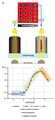
첫번째 방법은 인가하는 AC 전기 주파수 변화에 따른 세포들의 전체적인 움직임 변화를 통해 관측 하는 방법이 있다(도 1a 참조).The first method is to observe the change in the overall movement of the cells according to the applied AC electrical frequency change (see Figure 1a).
전극 구조안에 있는 세포들은 상대적으로 낮은 주파수(예를 들어 10 kHz) 에서는 negative 유전영동힘의 영향을 받아 전극의 중앙부분에 모이게 되는데, 이때 전극구조를 투과하고 있는 빛의 세기는 세포들이 중앙에서 가리기 때문에, 약해진다. 반대로 상대적으로 높은 주파수 (예를 들어 1 MHz) 에서는 세포는 positive 유전영동힘의 영향을 받아 전극의 가장자리 부분에 모이게 되며, 이때 전극 구조를 투과하고 있는 빛의 세기는 중앙부분을 차지고 하고 있던 세포들이 전극 가장자리로 이동하면서 훨씬 빛이 잘 투과되기 때문에 빛의 세기는 증가하게 된다. 이러한 세포의 움직임에 비례하는 빛의 세기 변화를 정량화하면 도 1a의 b 와 같은 곡선을 얻어낼 수 있으며, 이론적인 모델에 근거하여 세포의 cross-over frequency 를 찾을 수 있다. 장점으로는 한 번의 실험으로 유전영동힘에 대한 약 20,000개 세포반응을 알 수 있다고 주장하고 있고, 현재 상용화된 제품으로 출시되어 있다. 하지만, 유전영동힘에 대해 세포반응 각각을 관측하지 못하며, 한 well 내에 존재하는 수백, 수천개의 세포들의 반응에 대하여 대표값으로 확인 할 수밖에 없다는 한계점이 있다.Cells in the electrode structure collect at the center of the electrode under the influence of negative dielectric force at relatively low frequencies (eg 10 kHz), where the intensity of light passing through the electrode structure is obscured by the cells. It weakens. On the other hand, at relatively high frequencies (eg 1 MHz), the cells gather at the edges of the electrodes under the influence of positive dielectrophoretic forces, whereby the intensity of light passing through the electrode structure occupies the center portion. As the light travels to the edge of the electrode, the light intensity is increased because it is much more transparent. By quantifying the change in the intensity of light in proportion to the movement of the cell can be obtained a curve as shown in b of Figure 1a, and can find the cross-over frequency of the cell based on the theoretical model. The merit is that a single experiment can reveal about 20,000 cell responses to genophoretic forces, and is currently available as a commercial product. However, it is not possible to observe each cell response to the genetic kinetic forces, and there is a limitation that the representative value of the response of the hundreds or thousands of cells in a well is limited.
두 번째 방법으로는 각 세포 하나하나의 이동하는 좌표를 추적하는 방법이 있다. 이러한 방법은 DEP force에 반응하는 세포의 이동방향이 다르다는 것에 착안한다. 구체적으로 DEP force가 양의 방향일 때는 전기장의 세기가 가장 강한 곳으로 가며, DEP force가 음의 방향일 때에는 전기장의 세기가 가장 약한 곳으로 가기 때문에 세포가 유전영동 힘에 반응하여 움직이는 궤적을 분석하여 속도를 추정하면, DEP force와 hydrodynamic drag force 식에 근거하여 AC 주파수 변화에 대한 Re[CM] 파라미터값을 가정할 수 있다(도 1b 참조).The second method is to track the moving coordinates of each cell. This method focuses on the different direction of movement of cells in response to DEP force. Specifically, when DEP force is in the positive direction, the electric field strength goes to the strongest place. When DEP force is in the negative direction, the electric field strength goes to the weakest place, so the cell moves in response to the electrophoretic force. By estimating the velocity, the Re [CM] parameter value for the AC frequency change can be assumed based on the DEP force and the hydrodynamic drag force equation (see FIG. 1B).
하지만, 이러한 세포의 위치 추적 방식으로 구하는 방법의 경우, 상용화된 이미지 분석 프로그램(대표적으로 Image J)를 이용하여 분석하기 때문에, 궤적 분석에 최적화된 환경을 제공하지 못하며 (일반적으로 입자의 궤적을 정확하게 분석하기 위해서는 세포 주변의 배경이 일정한 밝기를 유지해야 한다. 전극모양이 주변에 있을 경우, 촬영한 모든 사진에서 각 세포의 위치를 정확하게 판별하기 위해서는 매우 많은 전처리 과정이 필요한 것으로 알고 있기 때문이다), 분석하는 세포수는 첫 번째 방법에 비해 적게 분석이 된다. 하지만, 유전영동힘에 대하여 각각의 세포에 대한 반응을 직접 관측하고 이를 통계적으로 분석하여 경향성을 확인하기 때문에, 적어도 관측한 세포군에 대한 대표값을 설명하기에는 부족함이 없다고 판단 할 수 있다.However, since the method of tracking the location of the cells is analyzed using a commercially available image analysis program (typically Image J), it does not provide an optimized environment for trajectory analysis (generally, the particle trajectory is accurately For the analysis, the background around the cells should be kept at a constant brightness, because when the electrode shape is around, it is known that a lot of pretreatment is necessary to accurately determine the position of each cell in every photograph taken.) The number of cells to be analyzed is analyzed less than the first method. However, since it directly observes the response to each cell with respect to the genophoretic force and statistically analyzes the trend, it can be judged that there is not enough to explain the representative value for at least the observed cell population.
이에, 본 발명자는 유전영동힘에 대하여 각각의 세포를 세포 한 개 단위로 manipulation이 가능하며, 주파수 변화에 따른 유전영동 힘의 방향이 변화되는 것에 의한 세포의 움직임 변화를 관측하였다. 이로부터, 유전영동 힘이 거의 존재하지 않는 구간을 유전영동힘의 식에 근거하여 추정하여, 세포의 cross-over frequency를 측정하는 새로운 방법을 제시하였다.Thus, the present inventors are able to manipulate each cell with respect to hereditary electrophoretic force, and observed the movement of the cell due to the change in the direction of the electrophoretic force according to the frequency change. From this, a new method of measuring the cross-over frequency of the cell was proposed by estimating the section in which the electrophoretic force is hardly present based on the equation of the electrophoretic force.
기존에 사용되는 세포의 교차주파수(cross-over frequency)를 찾는 방법인 AC 전기 주파수 변화에 따른 세포들의 움직임 변화 관측방법은 유전영동힘에 대한 세포 각각의 반응을 관찰하지 못하고 전체 세포들의 반응에 대한 대표값만 확인이 가능하다는 문제점이 있고, 세포 하나한의 좌표를 추적하는 방법은 한 번에 분석하는 세포수가 적다는 문제점이 있다.The method of observing the movement of cells according to the change of AC electric frequency, which is a method of finding the cross-over frequency of the cells, is not able to observe the response of each cell to the genetic electrophoretic force. There is a problem that only the representative value can be confirmed, and the method of tracking the coordinates of each cell has a problem that the number of cells to be analyzed at one time is small.
따라서 한 번의 실험으로 많은 세포수를 분석하는 동시에 세포 각각의 반응을 관찰할 수 있는 방법이 요구되고 있다.Therefore, a method of analyzing a large number of cells in one experiment and observing the responses of each cell is required.
본 발명은 세포의 교차주파수(cross-over frequency)을 찾기 위해 (a) 세포에 인가하는 교류주파수(Alternating Current Frequency)를 선정하는 단계; (b) 선정된 인가교류주파수를 변화시키면서 주파수 변화에 따른 세포 이동을 촬영하는 단계; 및 (c) 세포 이동 촬영 이미지를 통해 세포 궤적을 분석하고 이를 히스토그램화하는 단계를 포함하는, 세포의 궤적 분석을 통한 교차 주파수 측정방법을 제공함으로써 상기 과제를 해결하였다.The present invention comprises the steps of (a) selecting the alternating current (Alternating Current Frequency) applied to the cell to find the cross-over frequency of the cell; (b) photographing the cell movement according to the frequency change while changing the selected applied exchange frequency; And (c) analyzing a cell trajectory through histograms of cells and analyzing histograms of the cell trajectory, thereby providing a method of measuring cross-frequency using a cell trajectory analysis.
본 발명의 일 양태에서, 상기 단계 (a)의 인가교류주파수는 아래 [수학식 1]로 표기되는 클로시우스-모소티 인자(Clausius-Mossotti factor, CM factor)의 값을 -1 내지 0 또는 0.5 내지 1.5로 하는 교류주파수를 선정할 수 있다.In one aspect of the present invention, the applied alternating frequency of step (a) is a value of -1 to 0 or 0.5 of the Closius-Mossotti factor (CM factor) represented by
[수학식 1][Equation 1]

또한, 본 발명의 일 양태에서, 상기 단계 (b)의 변화시키면서 인가시키는 교류주파수는 0.01 내지 5 kHz 부터 증가시킬 수 있고, 바람직하게는 0.8 내지 2 kHz 부터 증가시킬 수 있다.In addition, in one aspect of the present invention, the alternating frequency applied while changing the step (b) can be increased from 0.01 to 5 kHz, preferably from 0.8 to 2 kHz.
또한, 본 발명의 일 양태에서, 상기 단계 (b)의 변화시키면서 인가시키는 교류주파수는 20 kHz 내지 1 MHz 부터 감소시킬 수 있고, 바람직하게는 38 내지 43 kHz 부터 감소시킬 수 있다.In addition, in one aspect of the present invention, the alternating frequency applied while changing the step (b) can be reduced from 20 kHz to 1 MHz, preferably from 38 to 43 kHz.
본 발명의 일 양태에서, 상기 교차주파수를 측정하는 단계에 측정된 교차주파수를 분석하는 단계를 포함하여 세포의 전기생리학적 특성을 관측할 수 있다.In one aspect of the invention, the step of measuring the cross-frequency comprising the step of analyzing the measured cross-frequency can observe the electrophysiological characteristics of the cell.
또한, 본 발명의 일 양태에서, 상기 분석된 교차주파수를 이용한 바이오센서를 제공할 수 있다.In addition, in one aspect of the present invention, it is possible to provide a biosensor using the analyzed crossover frequency.
또한, 본 발명의 일 양태에서, 상기 분석된 교차주파수를 이용한 세포의 흡착·분리 방법을 제공할 수 있다.In addition, in one aspect of the present invention, it is possible to provide a method for adsorption and separation of cells using the analyzed crossover frequency.
본 발명에 따른 세포의 궤적분석을 통해 교차주파수를 측정한 경우, 이상적으로 한 번의 실험으로 800개의 세포에 대하여 유전영동힘 반응을 관측할 수 있고, 복잡한 전극 위에서 촬영한 사진에 대하여 세포 궤적을 분석할 필요가 없기 때문에 분석과정이 단순화되어 시간을 절약할 수 있다.In the case of measuring the crossover frequency through the cell trajectory analysis according to the present invention, ideally, one can observe the genophoretic force response for 800 cells in one experiment, and analyze the cell trajectory for the photograph taken on the complex electrode. This can simplify the analysis process and save time.
도 1a 및 1b는 종래 측정 기술을 도식화한 것이다.
도 2는 세포의 교차주파수(cross-over frequency)를 측정하기 위한 유전영동 칩의 구조 및 구성을 나타낸 도이다.
(A) : 유전영동 칩의 구조
(B) : 유전영동 칩 전극의 구조
(C) : 유전영동 칩에 가라앉은 세포의 이동을 관측하기 위한 장비의 구조 및 구성
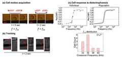
도 3은 세포의 교차주파수를 측정하기 위한 교류주파수 인가방법을 나타낸 도이다.
(A) : 세포의 교차주파수를 측정하기 위한 인가되는 교류주파수(AC frequency) 변화과정
(B) : 인가교류주파수를 1 kHz → 41 kHz → 1 kHz로 변화시켜주었을 때 세포의 이동궤적 (실험전 및 실험후 세포이미지 합성)
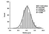
도 4는 유전영동칩에 투입되는 세포의 반지름을 나타낸 도이다.
도 5는 MCF-7 세포를 single-shell model이라고 가정하였을 때 1-50kHz 구간에서의 CM factor를 나타낸 그래프이며, MCF-7 세포에 교류주파수 41 kHz 와 1 kHz가 각각 인가되고 있을 때의 전극위 세포위치를 나타낸 도이다.
도 6은 인가교류주파수에 의한 전극위 세포의 위치를 나타낸 도이다.
도 7은 인가교류주파수가 증가 또는 감소했을 때 구심점과 세포들의 평균값 (Pntrap(x,y),Pptrap(x,y)) 의 거리차를 나타낸 도이다.
도 8은 유전영동힘에 반응하는 세포의 궤적 분석을 통해 교차주파수를 측정한 결과이다.1A and 1B illustrate a conventional measurement technique.
Figure 2 is a diagram showing the structure and configuration of the electrophoresis chip for measuring the cross-over frequency of the cell (cross-over frequency).
(A): structure of the electrophoretic chip
(B): structure of the electrophoretic chip electrode
(C): Structure and configuration of equipment for observing the movement of cells that have sunk on the electrophoretic chip
Figure 3 is a diagram showing an alternating frequency application method for measuring the cross-frequency of the cell.
(A) Process of changing the applied AC frequency to measure the crossover frequency of cells
(B): Movement trajectory of cells when the applied alternating frequency was changed from 1 kHz to 41 kHz to 1 kHz (synthesis of cell images before and after experiment)
Figure 4 is a diagram showing the radius of the cells introduced into the electrophoretic chip.
Figure 5 is a graph showing the CM factor in the 1-50kHz section assuming MCF-7 cells as a single-shell model, on the electrode when the alternating
6 is a view showing the position of the cells on the electrode by the applied alternating frequency.
Figure 7 shows the mean value of the centripetal point and cells when the applied AC frequency is increased or decreased (Pntrap (x, y) ,It is a figure which shows the distance difference ofPptrap (x, y) ).
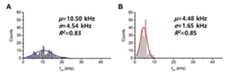
Figure 8 is the result of measuring the crossover frequency through the trajectory analysis of cells in response to the electrophoretic force.
이하, 본 발명이 속하는 기술분야에서 통상의 지식을 가진 자가 용이하게 실시할 수 있도록 본 발명의 실시형태를 들어 상세히 설명한다. 본 발명의 실시형태는 당업계에서 평균적인 지식을 가진 자에게 본 발명을 더욱 완전하게 설명하기 위해서 제공되는 것이다. 따라서 본 발명의 실시형태는 여러 가지 다른 형태로 변형될 수 있으며, 본 발명의 범위가 이하 설명하는 실시형태로 한정되는 것은 아니다.Hereinafter, embodiments of the present invention will be described in detail so that those skilled in the art can easily practice the present invention. Embodiments of the present invention are provided to more fully describe the present invention to those skilled in the art. Accordingly, embodiments of the present invention may be modified in various other forms, and the scope of the present invention is not limited to the embodiments described below.
본 발명의 명세서 전체에서, 어떤 부분이 어떤 구성 요소를 "포함"한다고 할 때, 이는 특별히 반대되는 기재가 없는 한 다른 구성 요소를 제외하는 것이 아니라 다른 구성 요소를 더 포함할 수 있는 것을 의미한다.Throughout the specification of the present invention, when a part is said to "include" a certain component, it means that it can further include other components, without excluding the other components unless otherwise stated.
본 발명의 명세서 전체에서 사용되는 용어 "~ (하는) 단계" 또는 "~의 단계"는 "~를 위한 단계"를 의미하지 않는다.As used throughout the specification of the present invention, the term "step of" or "step of" does not mean "step for".
본 발명에서, 하기 용어가 의미하는 바에 대해서 설명한다. 이는 발명을 이해를 위한 것으로, 용어의 의미는 성명되는 바에 의해 제한되지 않고, 본 발명이 속하는 기술분야에서 통상의 지식을 가진 자가 통상적으로 이해하는 용어의 의미를 포함한다.In the present invention, the following terms mean. This is for the purpose of understanding the invention, the meaning of the term is not limited by what is stated, and includes the meaning of terms commonly understood by those of ordinary skill in the art.
유전영동(Dielectrophoresis, DEP)은 극성이 없는 입자가 불균일한 교류 전기장에 노출되었을 때 쌍극성(dipole)이 입자에 유도되고, 유도된 입자와 전기장 사이의 상호작용으로 인해 힘이 발생하며, 발생된 힘을 통해 세포가 분극화(polarization)되는 것을 말한다. 분극성(polarizability)이 입자 주위를 둘러싼 용액의 분극성보다 클 경우 입자는 전기장이 강한 곳으로 이동하고(양의 유전영동, positive DEP). 반대로 입자의 분극성이 용액의 분극성보다 작을 경우에 입자는 전기장의 세기가 약한 방향으로 이동한다(음의 유전영동, negative DEP).Dielectrophoresis (DEP) is a process in which dipoles are induced in particles when nonpolar particles are exposed to a non-uniform alternating electric field, and force is generated due to the interaction between the induced particles and the electric field. It is the polarization of cells through force. If the polarizability is greater than the polarity of the solution surrounding the particles, the particles move to a strong electric field (positive DEP). Conversely, when the polarity of the particles is less than the polarity of the solution, the particles move in the direction of weak electric field strength (negative dielectric action, negative DEP).
CM factor는 클로시우스-모소티 인자(Clausius-Mossotti factor)를 나타내는 것으로, 클로시우스-모소티 인자 모델(The CM factor model)에서 세포에 대한 전기모델을 단일 쉘 모델 (single shell model)이라고 가정했을 때 하기 [수학식 1] 내지 [수학식 2]으로 구할 수 있다.The CM factor represents the Clousius-Mossotti factor, which assumes that the electrical model for the cells in the CM factor model is the single shell model. When [Equation 1] to [Equation 2] can be obtained.
[수학식 1][Equation 1]

[수학식 2][Equation 2]

상기 [수학식 2]에서

Re[CM]은 클로시우스-모소티 인자의 실수부를 의미하는 것으로, 유전영동현상에서 세포를 움직이게 하는 힘의 방향을 결정하는 요소이다.Re [CM] refers to the real part of Closius-Mossottie factor and is a factor that determines the direction of the force that moves the cell in the genetic phenomena.
유전영동힘(Dielectrophoresis force, DEP force)에 영향을 받는 세포의 반응을 추정하기 위해 세포의 모양을 구라고 가정하고, 구형태를 가지는 입자에 대한 유전영동힘의 식은 하기 [수학식 3]과 같다.In order to estimate the response of the cell affected by the Dielectrophoresis force (DEP force), it is assumed that the shape of the cell is sphere, the equation of the gene for the sphere-shaped particles is shown in [Equation 3] .
[수학식 3][Equation 3]

상기 [수학식 3]에서 FDEP는 유전영동힘이고 εmedi는 미디움 유전율이며 ERMS는 전기장의 제곱평균제곱근(root mean square, rms)이다.In Equation 3, FDEP is the dielectrophoretic force, εmedi is the medium permittivity, and ERMS is the root mean square (rms) of the electric field.
본 발명은 유전영동힘에 반응하는 세포의 궤적 분석을 통해 세포의 교차주파수(cross-over frequency)를 측정하는 방법에 관한 것이다.The present invention relates to a method for measuring the cross-over frequency of a cell by analyzing the trajectory of the cell in response to the electrophoretic force.
본 발명의 일 실시형태에 따르면, (a) 세포에 인가하는 교류주파수(Alternating Current Frequency)를 선정하는 단계; (b) 선정된 인가교류주파수를 변화시키면서 주파수 변화에 따른 세포 이동을 촬영하는 단계; 및 (c) 세포 이동 촬영 이미지를 통해 세포 궤적을 분석하고 이를 히스토그램화하는 단계를 포함하여 세포의 교차주파수를 측정할 수 있다.According to one embodiment of the invention, (a) selecting the alternating frequency (Alternating Current Frequency) to be applied to the cells; (b) photographing the cell movement according to the frequency change while changing the selected applied exchange frequency; And (c) analyzing the cell trajectory through histograms of cell migration and histograming the cell trajectory.
또한, 본 발명의 일 실시형태에 따르면, 이용되는 유전영동칩 상 저수조에 세포를 포함하는 조성물을 넣고 할 수 있다. 상기 세포를 포함하는 조성물은 세포 및 버퍼를 함유할 수 있다.In addition, according to one embodiment of the present invention, the composition containing the cells can be put in a reservoir on the electrophoretic chip used. The composition comprising the cells may contain cells and a buffer.
또한, 본 발명의 일 실시형태에 따르면, 상기 (a) 단계의 인가교류주파수는 클로시우스-모소티 인자의 값을 -1 내지 0인 교류주파수를 선정할 수 있고, 구체적으로는 클로시우스-모소티 인자 실수부의 값이 가장 작은 값에서 교류주파수를 선정할 수 있다.In addition, according to one embodiment of the present invention, the applied alternating frequency of step (a) may select an alternating frequency having a value of Closius-Mossottie factor from -1 to 0, specifically, Closius-Moso The AC frequency can be selected from the value with the smallest T-factor real part.
상기 클로시우스-모소티 인자의 값이 -0.5에 근접하는 경우 또는 가장 낮은 경우의 교류주파수에서는 Negative 유전영동힘을 세포에 효과적으로 전달할 수 있어 세포의 교차주파수를 측정하는데 효율적이다.When the value of the Closius-Mossottie factor approaches -0.5 or at the lowest AC frequency, the Negative Geneophoretic Force can be effectively transmitted to the cell, which is effective for measuring the cross-frequency of the cell.
또한, 본 발명의 일 실시형태에 따르면, 상기 (a) 단계의 인가교류주파수는 클로시우스-모소티 인자의 값을 0.5 내지 1.5로 하는 교류주파수로 선정할 수 있고, 구체적으로는 클로시우스-모소티 인자 실수부의 값이 가장 큰 값에서 교류주파수를 선정할 수 있다.In addition, according to one embodiment of the present invention, the applied alternating frequency of step (a) may be selected as an alternating frequency having a value of Closius-Mossottie factor from 0.5 to 1.5, specifically, Closius-Moso The AC frequency can be selected from the value of the real part of the tee factor.
상기 클로시우스-모소티 인자의 값이 최소 0.5 이상인 경우 또는 가장 큰 교류주파수에서는 Positive 유전영동힘을 세포에 효과적으로 전달할 수 있어 세포의 교차주파수를 척정하는데 효율적이다.When the value of the Closius-Mossoti factor is at least 0.5 or at the largest alternating frequency, it is possible to effectively transmit positive genophoretic force to the cell, which is effective in determining the cross frequency of the cell.
또한, 본 발명의 일 실시형태에 따르면, 상기 (b) 단계에서 인가되는 교류주파수를 점차 증가시킬 수 있고, 구체적으로 인가교류주파수를 0.01 내지 5 kHz부터 증가시킬 수 있으며, 바람직하게는 0.8 내지 2 kHz 부터 증가시킬 수 있다.In addition, according to one embodiment of the present invention, it is possible to gradually increase the AC frequency applied in the step (b), specifically the applied alternating frequency can be increased from 0.01 to 5 kHz, preferably 0.8 to 2 You can increase from kHz.
상기 인가교류주파수의 조건을 유지하는 시간은 1분 내지 3분일 수 있고, 인가하는 전압은 1 내지 3 Vp-p일 수 있다. 상기 인가전압을 정하는 기준은 1) 세포가 전압에 약 2시간동안 노출된 이후 살아있는 세포들의 수가 약 90% 이상인지 여부, 2) 세포의 모양이 눈에 띄게 변화하지 않는지 여부, 3) 유전영동힘의 방향과 크기에 따라 세포가 잘 이동하는지 여부에 따라 정할 수 있다. 또한, 인가전압은 세포가 포함된 용액의 구성성분에 따라 변화될 수 있다.The time for maintaining the conditions of the applied alternating frequency may be 1 minute to 3 minutes, the voltage to be applied may be 1 to 3 Vpp . The criteria for determining the applied voltage are: 1) whether the number of living cells is greater than about 90% after the cell has been exposed to the voltage for about 2 hours, 2) whether the shape of the cells does not change noticeably, and 3) the genetic behavior Depending on the direction and size of the cells can be determined depending on whether the cell moves well. In addition, the applied voltage may vary depending on the composition of the solution containing the cells.
또한, 본 발명의 일 실시형태에 따르면, 상기 (b) 단계에서 인가되는 교류주파수를 점차 감소시킬 수 있고, 구체적으로 인가교류주파수를 20 kHz 내지 1 MHz 부터 감소시킬 수 있으며, 바람직하게는 38 내지 43 kHz 부터 감소시킬 수 있다.In addition, according to one embodiment of the present invention, it is possible to gradually reduce the AC frequency applied in the step (b), specifically, the applied alternating frequency can be reduced from 20 kHz to 1 MHz, preferably 38 to Can be reduced from 43 kHz.
인가교류주파수를 1 kHz에서 41 kHz로 증가시킬 때, 안정된 네거티브 유전영동힘이 인가되는 교류주파수가 증가함에 따라 감소하며 클로시우스-모소티 인자 실수값이 음에서 양으로 넘어가게 되고 반대로 포지티브 유전영동 힘이 세포의 움직임에 영향을 주기 때문에 1 kHz에서 위치하고 있던 세포들이 전기장의 세기가 가장 강한 곳으로 이동할 수 있다. 또한, 인가교류주파수를 41 kHz에서 1 kHz로 감소시킬 때, 안정된 포지티브 유전영동힘이 인가되는 교류주파수가 감소함에 따라 감소하며 클로시우스-모소티 인자 실수값이 양에서 음으로 넘어가게 되고 반대로 네거티브 유전영동 힘이 세포의 움직임에 영향을 주기 때문에 41 kHz에서 위치하고 있던 세포들이 전기장의 세기가 가장 강한 곳으로 이동할 수 있다.Increasing the applied alternating frequency from 1 kHz to 41 kHz, the stable negative dielectrophoretic force decreases as the applied alternating frequency increases, and the Closius-Mossottie real number shifts from negative to positive and vice versa. Because the force affects the movement of the cells, the cells located at 1 kHz can move to the strongest electric field. In addition, when the applied alternating frequency is reduced from 41 kHz to 1 kHz, the AC frequency to which a stable positive dielectrophoretic force is applied decreases and the Closius-Mossottie real number value goes from positive to negative and vice versa. Because electrophoretic forces affect cell movement, cells located at 41 kHz can move to the strongest electric field.
또한, 본 발명의 일 실시형태에 따르면, 상기 (c) 단계에서 세포 궤적 분석 및 히스토그램화하는 단계는 상기 (b) 단계의 세포 이동을 촬영하는 단계에서 얻은 이미지를 이용하여 상용화된 영상처리그램을 이용할 수 있다. 보다 구체적으로 움직이는 세포의 위치좌표 (x, y) 각각을 히스토그램으로 표현하고 가우시안분포(Gaussian distribution) 여부를 확인하는 것을 포함할 수 있다. 이 때, (x, y) 좌표에 대한 가우시안 분포의 중앙값이 구심점이고, 상기 세포들의 구심점과 인가교류주파수가 변화했을 때 세포들의 위치 x축 및 y축의 거리차를 구해 세포의 교차주파수를 측정할 수 있다.In addition, according to an embodiment of the present invention, the cell trajectory analysis and histogram in the step (c) is a commercialized image processing diagram using the image obtained in the step of photographing the cell movement of the step (b) It is available. More specifically, each of the position coordinates (x, y) of the moving cell may be represented by a histogram and may include checking whether the Gaussian distribution. In this case, the center value of the Gaussian distribution with respect to the (x, y) coordinate is the centripetal point, and when the centripetal point and the applied exchange frequency of the cells change, the distance difference between the x-axis and the y-axis of the cells is determined to measure the crossover frequency of the cells. Can be.
본 발명의 구체적인 실시예에서, 본 발명자들은 유전영동 칩 위에 PDMS(Polydimethylsiloxane) 저수조를 올려둔 뒤 세포가 칩 표면 위에 위치할 때 까지 기다렸다. MCF-7 세포가 주어진 환경(세포를 둘러싼 버퍼의 전도도, 세포의 건강상태)에서 전도도가 60 μS/cm임을 확인하고, MCF-7 세포에 2분 동안 2 Vp-p 인가 이후 인가교류주파수 조건을 계속 유지하고 약 100초 동안의 움직임을 현미경에 장착된 CCD(Charge Coupled Device) 카메라를 통해 촬영하였다. 이때 인가되는 주파수는 네거티브 또는 포지티브 유전영동힘을 받을 수 있는 교류주파수로, MCF-7 세포가 비교적 작은 양의 클로시우스-모소티 인자 실수값을 나타내는 1 kHz 이고, 비교적 큰 양의 클로시우스-모소티 인자 실수값을 나타내는 41 kHz이다. 상기 MCF-7 세포에 인가하는 교류주파수의 조건을 1 kHz 에서 41 kHz 로 증가시키고 다시 41 kHz 에서 1 kHz 로 감소시킨 후, 촬영한 세포의 이동 이미지를 상용화된 영상처리프로그램을 사용하여 분석하였다(도 3 참조).In a specific embodiment of the present invention, the inventors placed a PDMS (Polydimethylsiloxane) reservoir on the electrophoretic chip and waited until the cells were placed on the chip surface. Confirm that the MCF-7 cells have a conductivity of 60 μS / cm in a given environment (conductivity of the buffer surrounding the cells, the health of the cells), and continue to apply the applied frequency conditions after applying 2 Vpp to the MCF-7 cells for 2 minutes. The movement for about 100 seconds was maintained and photographed through a CCD (Charge Coupled Device) camera mounted on a microscope. In this case, the applied frequency is an alternating frequency capable of receiving a negative or positive genophoretic force, which is 1 kHz in which MCF-7 cells exhibit a relatively small amount of Closius-Mossott factor real value, and a relatively large amount of Closius-Moss. It is 41 kHz indicating the tee factor real value. After increasing the conditions of the alternating frequency applied to the MCF-7 cells from 1 kHz to 41 kHz and again from 41 kHz to 1 kHz, the moving images of the photographed cells were analyzed using a commercially available image processing program ( 3).
이동한 각 세포들의 위치 x, y에 대한 히스토그램을 만든 뒤, 가우시안분포 형성여부를 확인하였다. 교류주파수 1kHZ 를 인가한 MCF-7 세포는 네거티브 유전영동힘에 의해 (0, 0) 좌표에 안정적으로 위치하는 것을 확인하고, 세포 위치 x, y의 히스토그램 평균값을Pntrap(x,y) 으로 정의하였다. 또한 교류주파수 41 kHz를 인가한 MCF-7 세포가 포지티브 유전영동힘에 의해 (-15.8354, -2.6358)에 위치하는 것을 확인하고, 세포위치 x, y의 히스토그램 평균값을Pptrap(x,y) 으로 정의하였다(도 6 참조). 인가교류주파수가 증가 또는 감소했을 때 각각의 세포와 구심점과의 거리차를 측정하고 분석하여 MCF-7 세포의 교차주파수 값이 4.48kHz 내지 10.50kHz 임을 확인하였고, 수식을 통해 계산된 MCF-7 세포의 교차주파수 7.94 kHz가 상기 범위 사이에 있음을 확인하였다(도 8 참조).After making histograms of the positions x and y of each of the cells, the Gaussian distribution was confirmed. MCF-7 cells with alternating frequency 1kHZ were found to be stably located at (0, 0) coordinates by the negative genophoretic force, and the histogram mean of cell positions x and y was defined asPntrap (x, y) . It was. In addition, MCF-7 cells with an alternating frequency of 41 kHz were confirmed to be located at (-15.8354, -2.6358) by positive genophoretic force, and the histogram mean values of the cell positions x and y were set toPptrap (x, y) . Defined (see FIG. 6). When the applied AC was increased or decreased, the distance difference between each cell and the centripetal point was measured and analyzed to confirm that the cross-frequency value of MCF-7 cells was 4.48 kHz to 10.50 kHz. The crossover frequency of 7.94 kHz was found to be between the above ranges (see Fig. 8).
본 발명은 유전영동힘에 반응하는 세포의 궤적 분석을 통해 세포의 교차주파수를 측정한 후 상기 측정된 교차주파수를 분석하는 단계를 포함할 수 있고, 상기 교차주파수를 분석하여 세포의 전기생리학적 특성을 분석할 수 있다.The present invention may include the step of analyzing the measured cross-frequency after measuring the cross-frequency of the cell through the trajectory analysis of the cell in response to the electrophoretic force, the electrophysiological characteristics of the cell by analyzing the cross-frequency Can be analyzed.
상기 교차주파수는 맥스웰 응력 텐서(Maxwell stress tensor, MST) 방법을 도입하여, 세포막과 세포질의 전기적파라미터(세포막 커패시턴스, 세포질 전도도) 변화에 의한 세포표면에서의 국부적인 유전영동 힘에 따른 세포의 생물리학적 특징변화를 연구하고 수치 시뮬레이션으로 제시될 수 있다. 상기 맥스웰 응력 텐서는 τ로 하기 [수학식 4]로 정의된다.The crossover frequency is based on the Maxwell stress tensor (MST) method, and the biophysiology of the cell according to the localized electrophoretic force at the cell surface due to the change of cell membrane and cytoplasmic electrical parameters (cell capacitance, cytosol conductivity) Changes in physical characteristics can be studied and presented in numerical simulations. The Maxwell stress tensor is defined by
[수학식 4][Equation 4]

이때, E는 전기장이고 I는 단위텐서이다. 또한, 입자부피에 대한 유전영동힘(DEP)은 하기 [수학식 5]으로 정의된다.Where E is the electric field and I is the unit tensor. In addition, the dielectrophoretic force (DEP) for the particle volume is defined by
[수학식 5][Equation 5]

이때, V는 부피이고 S는 부피를 둘러싸는 표면이며 n은 S의 단위벡터이다. 또한, 특정 부피의 전자기력은 하기 [수학식 6]로 정의된다.Where V is the volume, S is the surface surrounding the volume, and n is the unit vector of S. In addition, the specific force of the electromagnetic force is defined by
[수학식 6][Equation 6]

상기 교차주파수를 분석하여 세포의 경향성을 파악하고, 파악한 경향성을 통해주어진 외부적 자극에 반응하여 세포의 세포막에서 발생되는 변화에 대한 해석이 가능하다. 세포계는 암 세포(cancer cell), 줄기세포(stem cell), 박테리아(bacteria), 바이러스(virus) 등 제한이 없으며, 고유 전기생리학적 특성을 밝힘으로써, 외부환경요인에 의한 세포의 변화를 구별할 수 있다.Analyze the cross-frequency to determine the trend of the cell, through the trend Interpretation of changes in cell membranes in response to a given external stimulus is possible. The cell system has no limitations such as cancer cells, stem cells, bacteria, viruses, etc., and it is possible to distinguish cell changes caused by external environmental factors by revealing unique electrophysiological characteristics. Can be.
본 발명의 일 실시형태에 따르면, 본 발명은 유전영동힘에 반응하는 세포의 궤적분석을 통해 측정된 교차주파수 및 상기 교차주파수를 통해 분석된 세포의 전기생리학적 특성을 이용한 바이오센서를 제공할 수 있다.According to one embodiment of the invention, the present invention can provide a biosensor using the cross-frequency measured through the trajectory analysis of the cell in response to the electrophoretic force and the electrophysiological characteristics of the cell analyzed through the cross-frequency. have.
본 발명의 일 실시형태에 따르면, 본 발명은 유전영동힘에 반응하는 세포의 궤적분석을 통해 측정된 교차주파수 및 상기 교차주파수를 통해 분석된 세포의 전기생리학적 특성을 이용한 세포의 흡착·분리 방법을 제공할 수 있다.According to an embodiment of the present invention, the present invention provides a method for adsorption / separation of cells using a crossover frequency measured through a trajectory analysis of a cell in response to genophoretic force and electrophysiological characteristics of the cell analyzed through the crossover frequency. Can be provided.
이하 본 발명을 실시예 및 실험예를 통해 보다 상세히 설명한다. 다만 하기 실시예 및 실험예는 본 발명의 이해를 돕기 위한 것이지 본 발명의 권리범위를 이로 한정하는 것을 의도하지 않는다.Hereinafter, the present invention will be described in more detail with reference to Examples and Experimental Examples. However, the following Examples and Experimental Examples are intended to help the understanding of the present invention and are not intended to limit the scope of the present invention thereto.
<실시예1> 유전영동힘에 의한 MCF-7의 위치 변화 측정Example 1 Measurement of Position Change of MCF-7 by Dielectrophoretic Force
실시예 <1-1> 네거티브 유전영동힘을 받을 수 있는 교류주파수 선정 후 MCF-7 세포에 처리Example <1-1> Treatment with MCF-7 Cells after Selection of Alternating Frequency to Receive Negative Dielectrophoretic Force
실험을 위하여 유전영동 칩 위에 PDMS(Polydimethylsiloxane) 저수조를 올려둔 뒤, MCF-7 세포가 포함된 용액을 넣고 커버글라스로 밀폐시켰다. 이후 Top view 방향에서 CCD(Charge Coupled Device) 카메라를 이용하여 칩 표면에 현미경 대물렌즈의 초점이 맞도록 조정하며, 세포가 칩 표면 위에 위치할 때까지 기다렸다.For experiments, a PDMS (Polydimethylsiloxane) reservoir was placed on the electrophoretic chip, and the solution containing MCF-7 cells was added and sealed with a cover glass. Then, using a CCD (Charge Coupled Device) camera in the top view, the microscope objective was adjusted to focus on the chip surface, and waited until the cells were positioned on the chip surface.
칩 표면 위에 MCF-7 세포가 위치한 후 네거티브 유전영동 힘을 받을 수 있는 주파수 AC 1kHz를 MCF-7 세포에 2분 동안 2 Vp-p 인가 이후 인가교류주파수 조건을 계속 유지하고 약 100초 동안의 움직임을 현미경에 장착된 카메라로 촬영하였다(도 3의 B 참조).After MCF-7 cells are placed on the chip surface, the frequency AC 1kHz that can receive negative genophoretic force is applied to MCF-7 cells for 2 minutes at 2 Vpp, then the applied alternating frequency condition is maintained and the movement for about 100 seconds is maintained. The image was taken with a camera mounted on a microscope (see B of FIG. 3).
상기 네거티브 유전영동 힘을 받을 수 있는 교류주파수 1kHz는 클로시우스-모소티 인자(Clausius-Mossotti factor, CM factor)의 음의 값이 -0.5에 근접하거나 그 값을 가장 낮게 하는 교류주파수를 선정한 값이다.The AC frequency that can be subjected to the negative dielectrophoretic force 1kHz is a value that selects an AC frequency at which the negative value of the Clausius-Mossotti factor (CM factor) approaches -0.5 or the lowest value thereof. .
실시예 <1-2> 포지티브 유전영동힘 선정 후 MCF-7 세포에 처리Example <1-2> Treatment with MCF-7 cells after selection of positive genophoretic force
실시예 <1-1>의 안정적으로 위치한 MCF-7에 포지티브 유전영동 힘을 받을 수 있는 주파수 AC 41kHz까지 증가시킨 후, MCF-7 세포에 상기 실시예 <1-1>과 동일한 방법으로 촬영하였다(도 3의 B 참조).MCF-7 stably located in Example <1-1> was increased to a frequency of 41 kHz, which was capable of receiving positive genophoretic force, and then MCF-7 cells were photographed in the same manner as in Example <1-1>. (See B of FIG. 3).
상기 포지티브 유전영동 힘을 받을 수 있는 교류주파수 41kHz는 클로시우스-모소티 인자의 양의 값이 최소 +0.5 이상 또는 그 값이 가장 큰 교류주파수를 선정한 값이다.An AC frequency of 41 kHz that is capable of receiving the positive dielectrophoretic force is a value that selects an AC frequency having a positive value of Closius-Mossottie factor of at least +0.5 or greater.
실시예 <1-3> 네거티브 유전영동힘에 의해 이동한 MCF-7 세포의 좌표 확인Example <1-3> Confirmation of coordinates of MCF-7 cells migrated by negative genophoretic force
상기 실시예<1-1>에서 촬영한 유체내에서 움직이는 세포의 위치를 상용화된 영상처리프로그램을 사용하여 분석한 결과, MCF-7 세포가 (0,0) 좌표에 안정적으로 위치해 있음을 확인하였다.As a result of analyzing the position of the moving cells in the fluid photographed in Example <1-1> using a commercially available image processing program, it was confirmed that MCF-7 cells were stably positioned at (0,0) coordinates. .
실시예 <1-4> 포지티브 유전영동힘에 의해 이동한 MCF-7 세포의 좌표 확인Example 1-4 Confirmation of Coordinates of MCF-7 Cells Moved by Positive Dielectrophoretic Force
상기 실시예 <1-2>에서 촬영한 유체내 움직이는 세포의 위치를 실시예<1-3>과 동일한 방법으로 분석한 결과, MCF-7 세포가 (-15.8354, -2.6358) 좌표에 위치해있음을 확인하였다.As a result of analyzing the position of the moving cell in the fluid photographed in Example <1-2> in the same manner as in Example <1-3>, MCF-7 cells were located at the coordinates of (-15.8354, -2.6358). Confirmed.
<실험예 1> MCF-7 세포의 교차주파수 확인Experimental Example 1 Cross-Frequency Check of MCF-7 Cells
실험예 <1-1> 세포위치 평균값 확인Experimental Example <1-1> Confirmation of average cell position
상기 실시예 <1-3>에서 확인한 네거티브 유전영동힘에 의해 이동한 MCF-7 세포의 각각의 위치좌표 (x,y) 및 실시예 <1-4>에서 확인한 포지티브 유전영동힘에 의해 이동한 MCF-7 세포의 각각의 위치좌표 (x,y)를 히스토그램으로 표현하고, 가우시안분포 형성여부를 확인하였다. 이때 x,y 좌표에 대한 가우시안분포의 중앙값을 구심점이라고 정의하고, 확인된 세포위치 x,y 히스토그램 평균값을Pntrap(x,y)및Pptrap(x,y) 라고 정의하였다.The positional coordinates (x, y) of the MCF-7 cells shifted by the negative genophoretic force identified in Example <1-3> and the positive genophoretic force identified in Example <1-4>. The positional coordinates (x, y) of MCF-7 cells were expressed by histogram, and Gaussian distribution was confirmed. In this case, the median value of the Gaussian distribution with respect to the x, y coordinates was defined as the centripetal point, and the identified cell position x, y histogram mean values were defined asPntrap (x, y) andPptrap (x, y) .
실험예 <1-2> MCF-7 세포의 교차주파수 확인Experimental Example <1-2> Cross-Frequency Check of MCF-7 Cells
인가교류주파수가 증가 또는 감소했을 때 각각의 세포와 구심점과의 거리차를 측정한 후, 거리차가 x와 y 위치의 히스토그램의 표준편차의 3배보다 모두 큰 경우의 인가교류주파수를 기록한다. 해당 인가교류주파수 이후에 x축 또는 y축 거리차가 다시 히스토그램의 표준편차의 3배 이하로 감소하는지 확인하고, 없을 경우 상기 인가교류주파수를 세포의 교차주파수로 정의하였다.Measure the distance difference between each cell and the centripetal point when the applied frequency increases or decreases, and record the applied frequency when the distance difference is greater than three times the standard deviation of the histogram of the x and y positions. After the applied AC frequency, the x-axis or y-axis distance difference again decreased to less than 3 times the standard deviation of the histogram, and if not, the applied AC frequency was defined as the crossover frequency of the cells.
구한 교차주파수를 다시 히스토그램으로 표현한 후, 히스토그램에 대한 평균과 표준편차를 계산하여 세포군에 대한 교차주파수를 정의하였다.After the obtained crossover frequency was expressed as a histogram, the crossover frequency for the cell population was defined by calculating the mean and standard deviation of the histogram.
그 결과, 본 발명에 따라 측정된 CM factor가 0이 되는 MCF-7 세포의 교차주파수 값은 4.48kHz에서 10.50kHz로, 수식을 통해 이론적으로 계산된 교차주파수 7.94kHz와 유사한 것을 확인하였다.As a result, the cross-frequency value of MCF-7 cells having a CM factor of 0 according to the present invention was 4.48 kHz to 10.50 kHz, which was similar to the theoretically calculated cross-frequency 7.94 kHz.
Claims (15)
Translated fromKorean(b) 선정된 인가교류주파수를 변화시키면서 주파수 변화에 따른 세포 이동을 촬영하는 단계; 및
(c) 세포 이동 촬영 이미지를 통해 세포 궤적을 분석하고 이를 히스토그램화하는 단계를 포함하는, 세포 궤적 분석을 통한 교차 주파수(cross-over frequency) 측정방법.
(a) selecting an alternating current frequency applied to the cell;
(b) photographing the cell movement according to the frequency change while changing the selected applied exchange frequency; And
(c) analyzing the cell trajectory via histogram image and histogramting the cell trajectory, wherein the cross-over frequency measurement method is performed through the cell trajectory analysis.
유전영동칩 상 저수조에 세포를 포함하는 조성물을 넣고 측정하는, 세포 궤적 분석을 통한 교차 주파수 측정방법.
The method of claim 1,
Cross-frequency measurement method through the cell trajectory analysis to put the composition containing the cells in the reservoir on the electrophoretic chip.
상기 세포를 포함하는 조성물은 세포 및 버퍼를 함유하는, 세포 궤적 분석을 통한 교차 주파수 측정방법.
The method of claim 2,
The composition comprising the cells contains cells and a buffer, the cross-frequency measurement method through cell trajectory analysis.
상기 (a) 단계의 인가교류주파수는 하기 [수학식 1]로 표기되는 클로시우스-모소티 인자(Clausius-Mossotti factor, CM factor)의 값을 -1 내지 0으로 하는 교류주파수를 선정하는, 세포의 궤적 분석을 통한 교차주파수 측정방법 :
[수학식 1]

The method of claim 1,
The applied alternating frequency of step (a) is a cell for selecting an alternating frequency in which the value of Closius-Mossotti factor (CM factor) represented by Equation 1 below is -1 to 0. Measurement of Cross-Frequency through Trajectory Analysis of:
[Equation 1]
상기 (a) 단계에서 입력되는 인가교류주파수는 [수학식 1]을 이용해 클로시우스-모소티 인자 실수부의 값이 가장 작은 값에서 교류주파수를 선정하는, 세포의 궤적 분석을 통한 교차주파수 측정방법.
The method of claim 4, wherein
The applied alternating frequency input in the step (a) is to select the alternating frequency at the smallest value of the Closius-Mossotti factor real part using [Equation 1], the cross-frequency measurement method through the cell trajectory analysis.
상기 (a) 단계에서 입력되는 인가교류주파수는 하기 [수학식 1]을 이용해 클로시우스-모스티 인자의 값을 0.5 내지 1.5로 하는 교류주파수를 선정하는, 세포의 궤적분석을 통한 교차 주파수 측정방법 :
[수학식 1]

The method of claim 1,
The applied alternating frequency input in the step (a) is to select an alternating frequency of 0.5 to 1.5 of Closius-Mostey factor using Equation 1 below. :
[Equation 1]
상기 (a) 단계에서 입력되는 인가교류주파수는 [수학식 1]을 이용해 클로시우스-모소티 인자 실수부의 값이 가장 큰 값에서 교류주파수를 선정하는, 세포의 궤적분석을 통한 교차주파수 측정방법.
The method of claim 6,
The applied alternating current frequency input in step (a) is to select an alternating frequency at a value of the largest value of the Closius-Mossoti factor real part using [Equation 1], the cross-frequency measurement method through the cell trajectory analysis.
상기 (b) 단계에서 입력하는 인가교류주파수를 증가시키는, 세포의 궤적 분석을 통한 교차주파수 측정방법.
The method of claim 1,
The cross-frequency measurement method through the trajectory analysis of the cell to increase the applied exchange frequency input in the step (b).
상기 인가교류주파수를 0.01 내지 5 kHz부터 증가시키는, 세포의 궤적 분석을 통한 교차주파수 측정방법.
The method of claim 8,
The applied alternating frequency to increase from 0.01 to 5 kHz, cross-frequency measurement method through the trajectory analysis of the cell.
상기 (b) 단계에서 입력하는 인가교류주파수를 감소시키는, 세포의 궤적 분석을 통한 교차주파수 측정방법.
The method of claim 1,
Cross-frequency measurement method through the cell trajectory analysis to reduce the applied AC frequency input in the step (b).
상기 (b) 단계에서 입력하는 인가교류주파수를 20 kHz 내지 1 MHz 부터 감소시키는, 세포의 궤적 분석을 통한 교차주파수 측정방법.
The method of claim 10,
A method of measuring cross-frequency through a cell trajectory analysis to reduce the applied AC frequency input in the step (b) from 20 kHz to 1 MHz.
상기 (b) 단계에서 입력하는 인가교류주파수를 38 내지 43 kHz 부터 감소시키는, 세포의 궤적 분석을 통한 교차주파수 측정방법.
The method of claim 11,
The cross-frequency measurement method through the cell trajectory analysis to reduce the applied alternating frequency input from the step (b) from 38 to 43 kHz.
A biosensor using a crossover frequency measured by any one of claims 1 to 12.
A method for adsorption / separation of cells using a crossover frequency measured according to any one of claims 1 to 12.
측정된 교차주파수를 분석하는 단계를 포함하는,
세포의 전기생리학적 특성을 분석하는 방법.Measuring a crossover frequency according to the method of any one of claims 1 to 12; And
Analyzing the measured crossover frequency;
Method for analyzing electrophysiological properties of cells.
Applications Claiming Priority (2)
| Application Number | Priority Date | Filing Date | Title |
|---|---|---|---|
| KR20180103531 | 2018-08-31 | ||
| KR1020180103531 | 2018-08-31 |
Publications (2)
| Publication Number | Publication Date |
|---|---|
| KR20200026171Atrue KR20200026171A (en) | 2020-03-10 |
| KR102230602B1 KR102230602B1 (en) | 2021-03-22 |
Family
ID=69801258
Family Applications (1)
| Application Number | Title | Priority Date | Filing Date |
|---|---|---|---|
| KR1020190108352AActiveKR102230602B1 (en) | 2018-08-31 | 2019-09-02 | Measurement of cross-over frequency of cells through trajectory analysis of cells responding to dielectrophoretic force |
Country Status (1)
| Country | Link |
|---|---|
| KR (1) | KR102230602B1 (en) |
Citations (7)
| Publication number | Priority date | Publication date | Assignee | Title |
|---|---|---|---|---|
| US20040112748A1 (en)* | 2002-12-12 | 2004-06-17 | Lee Richard Stanley | Dielectrophoretic particle profiling system and method |
| WO2007091450A1 (en)* | 2006-02-10 | 2007-08-16 | Kochi University Of Technology | Characteristic analyzing apparatus and method utilizing dielectric migration of granular substance by angularly modulated wave |
| KR101599606B1 (en) | 2014-04-01 | 2016-03-03 | 연세대학교 원주산학협력단 | Method for measurement of biomolecular binding forces using lateral dielectrophoresis force spectroscopy |
| JP2017134020A (en)* | 2016-01-29 | 2017-08-03 | 株式会社Afiテクノロジー | Analysis device and separation device |
| JP2018514195A (en)* | 2015-03-26 | 2018-06-07 | ユニバーシティー オブ ヒューストン システム | Integrated cellular functionality and molecular profiling |
| KR20190024175A (en) | 2017-08-31 | 2019-03-08 | 연세대학교 원주산학협력단 | Method for measurement of binding forces between biomaterials and proteins using dielectrophoresis force spectroscopy |
| WO2020081720A1 (en)* | 2018-10-16 | 2020-04-23 | Yale University | Electronic system for capture and characterization of particles |
- 2019
- 2019-09-02KRKR1020190108352Apatent/KR102230602B1/enactiveActive
Patent Citations (7)
| Publication number | Priority date | Publication date | Assignee | Title |
|---|---|---|---|---|
| US20040112748A1 (en)* | 2002-12-12 | 2004-06-17 | Lee Richard Stanley | Dielectrophoretic particle profiling system and method |
| WO2007091450A1 (en)* | 2006-02-10 | 2007-08-16 | Kochi University Of Technology | Characteristic analyzing apparatus and method utilizing dielectric migration of granular substance by angularly modulated wave |
| KR101599606B1 (en) | 2014-04-01 | 2016-03-03 | 연세대학교 원주산학협력단 | Method for measurement of biomolecular binding forces using lateral dielectrophoresis force spectroscopy |
| JP2018514195A (en)* | 2015-03-26 | 2018-06-07 | ユニバーシティー オブ ヒューストン システム | Integrated cellular functionality and molecular profiling |
| JP2017134020A (en)* | 2016-01-29 | 2017-08-03 | 株式会社Afiテクノロジー | Analysis device and separation device |
| KR20190024175A (en) | 2017-08-31 | 2019-03-08 | 연세대학교 원주산학협력단 | Method for measurement of binding forces between biomaterials and proteins using dielectrophoresis force spectroscopy |
| WO2020081720A1 (en)* | 2018-10-16 | 2020-04-23 | Yale University | Electronic system for capture and characterization of particles |
Non-Patent Citations (3)
| Title |
|---|
| Determination of Cell Membrane Capacitance and Conductance via Optically Induced Electrokinetics, Wenfeng Liang et al., Biophysical Journal 113 (7), 1531(2017) |
| Label-Free Electric Monitoring of Human Cancer Cells as a Potential Diagnostic Tool, Clarisse Vaillier et al., Anal. Chem. 88(18), 9022-9028 (2016) |
| Rhythmic potassium transport regulates the circadian clock in human red blood cells, Erin A. et al., Nat. Commun. 8 (1), 1978(2017) |
Also Published As
| Publication number | Publication date |
|---|---|
| KR102230602B1 (en) | 2021-03-22 |
Similar Documents
| Publication | Publication Date | Title |
|---|---|---|
| Spencer et al. | High-speed single-cell dielectric spectroscopy | |
| Honrado et al. | A neural network approach for real-time particle/cell characterization in microfluidic impedance cytometry | |
| Feng et al. | A microfluidic device integrating impedance flow cytometry and electric impedance spectroscopy for high-efficiency single-cell electrical property measurement | |
| Zheng et al. | Microfluidic characterization of specific membrane capacitance and cytoplasm conductivity of singlecells | |
| JP5241044B2 (en) | Fine particle measuring apparatus and fine particle measuring method | |
| JP4105767B2 (en) | Apparatus and method for testing particles using dielectrophoresis | |
| US11927560B2 (en) | Bio/chemical material extraction and assay | |
| Reale et al. | High-throughput electrical position detection of single flowing particles/cells with non-spherical shape | |
| CA2999683A1 (en) | Microfluidic device for selection of semen | |
| US20100193358A1 (en) | Microparticle measuring apparatus and microparticle measuring method | |
| Sarangadharan et al. | High field modulated FET biosensors for biomedical applications | |
| Fang et al. | Floating-electrode-enabled impedance cytometry for single-cell 3D localization | |
| Jaffe et al. | Multi-frequency dielectrophoretic characterization of single cells | |
| Lavi et al. | Dielectrophoretic detection of electrical property changes of stored human red blood cells | |
| Shi et al. | A label-free and low-power microelectronic impedance spectroscopy for characterization of exosomes | |
| Cui et al. | Concurrently probing the mechanical and electrical characteristics of living cells via an integrated microdevice | |
| Chakraborty et al. | Low frequency impedimetric cell counting: analytical modeling and measurements | |
| Zheng et al. | Continuous-flow, electrically-triggered, single cell-level electroporation | |
| US11559817B2 (en) | Using electrokinetic forces to manipulate suspended particles | |
| CN115651831A (en) | Microfluidic chip, system and method of use thereof | |
| Sherif et al. | Optimization design of interdigitated microelectrodes with an insulation layer on the connection tracks to enhance efficiency of assessment of the cell viability | |
| KR20200026171A (en) | Measurement of cross-over frequency of cells through trajectory analysis of cells responding to dielectrophoretic force | |
| JP2007006858A (en) | Microbial test chip and microbiological test method | |
| Français et al. | Single cell electrical characterization techniques | |
| Abd Samad et al. | Dielectrophoresis velocities response on tapered electrode profile: Simulation and experimental |
Legal Events
| Date | Code | Title | Description |
|---|---|---|---|
| A201 | Request for examination | ||
| PA0109 | Patent application | Patent event code:PA01091R01D Comment text:Patent Application Patent event date:20190902 | |
| PA0201 | Request for examination | ||
| PG1501 | Laying open of application | ||
| E902 | Notification of reason for refusal | ||
| PE0902 | Notice of grounds for rejection | Comment text:Notification of reason for refusal Patent event date:20201104 Patent event code:PE09021S01D | |
| AMND | Amendment | ||
| E601 | Decision to refuse application | ||
| PE0601 | Decision on rejection of patent | Patent event date:20210210 Comment text:Decision to Refuse Application Patent event code:PE06012S01D Patent event date:20201104 Comment text:Notification of reason for refusal Patent event code:PE06011S01I | |
| AMND | Amendment | ||
| PX0901 | Re-examination | Patent event code:PX09011S01I Patent event date:20210210 Comment text:Decision to Refuse Application Patent event code:PX09012R01I Patent event date:20210129 Comment text:Amendment to Specification, etc. | |
| PX0701 | Decision of registration after re-examination | Patent event date:20210309 Comment text:Decision to Grant Registration Patent event code:PX07013S01D Patent event date:20210222 Comment text:Amendment to Specification, etc. Patent event code:PX07012R01I Patent event date:20210210 Comment text:Decision to Refuse Application Patent event code:PX07011S01I Patent event date:20210129 Comment text:Amendment to Specification, etc. Patent event code:PX07012R01I | |
| X701 | Decision to grant (after re-examination) | ||
| GRNT | Written decision to grant | ||
| PR0701 | Registration of establishment | Comment text:Registration of Establishment Patent event date:20210316 Patent event code:PR07011E01D | |
| PR1002 | Payment of registration fee | Payment date:20210316 End annual number:3 Start annual number:1 | |
| PG1601 | Publication of registration | ||
| PR1001 | Payment of annual fee | Payment date:20240308 Start annual number:4 End annual number:4 | |
| PR1001 | Payment of annual fee | Payment date:20250317 Start annual number:5 End annual number:5 |