KR20200017066A - Device for flaw visualization of the 3d structures based on fully non-contact laser ultrasonic wave imaging process and the method for the same - Google Patents
Device for flaw visualization of the 3d structures based on fully non-contact laser ultrasonic wave imaging process and the method for the sameDownload PDFInfo
- Publication number
- KR20200017066A KR20200017066AKR1020180092224AKR20180092224AKR20200017066AKR 20200017066 AKR20200017066 AKR 20200017066AKR 1020180092224 AKR1020180092224 AKR 1020180092224AKR 20180092224 AKR20180092224 AKR 20180092224AKR 20200017066 AKR20200017066 AKR 20200017066A
- Authority
- KR
- South Korea
- Prior art keywords
- laser beam
- inspection object
- mirror
- reflected
- measuring unit
- Prior art date
- Legal status (The legal status is an assumption and is not a legal conclusion. Google has not performed a legal analysis and makes no representation as to the accuracy of the status listed.)
- Granted
Links
Images


Classifications
- G—PHYSICS
- G01—MEASURING; TESTING
- G01N—INVESTIGATING OR ANALYSING MATERIALS BY DETERMINING THEIR CHEMICAL OR PHYSICAL PROPERTIES
- G01N29/00—Investigating or analysing materials by the use of ultrasonic, sonic or infrasonic waves; Visualisation of the interior of objects by transmitting ultrasonic or sonic waves through the object
- G01N29/22—Details, e.g. general constructional or apparatus details
- G01N29/24—Probes
- G01N29/2418—Probes using optoacoustic interaction with the material, e.g. laser radiation, photoacoustics
- G—PHYSICS
- G01—MEASURING; TESTING
- G01H—MEASUREMENT OF MECHANICAL VIBRATIONS OR ULTRASONIC, SONIC OR INFRASONIC WAVES
- G01H9/00—Measuring mechanical vibrations or ultrasonic, sonic or infrasonic waves by using radiation-sensitive means, e.g. optical means
- G01H9/002—Measuring mechanical vibrations or ultrasonic, sonic or infrasonic waves by using radiation-sensitive means, e.g. optical means for representing acoustic field distribution
- G—PHYSICS
- G01—MEASURING; TESTING
- G01N—INVESTIGATING OR ANALYSING MATERIALS BY DETERMINING THEIR CHEMICAL OR PHYSICAL PROPERTIES
- G01N29/00—Investigating or analysing materials by the use of ultrasonic, sonic or infrasonic waves; Visualisation of the interior of objects by transmitting ultrasonic or sonic waves through the object
- G01N29/04—Analysing solids
- G01N29/06—Visualisation of the interior, e.g. acoustic microscopy
- G01N29/0654—Imaging
- G—PHYSICS
- G02—OPTICS
- G02B—OPTICAL ELEMENTS, SYSTEMS OR APPARATUS
- G02B27/00—Optical systems or apparatus not provided for by any of the groups G02B1/00 - G02B26/00, G02B30/00
- G02B27/30—Collimators
Landscapes
- Physics & Mathematics (AREA)
- General Physics & Mathematics (AREA)
- Chemical & Material Sciences (AREA)
- Immunology (AREA)
- Health & Medical Sciences (AREA)
- Analytical Chemistry (AREA)
- Biochemistry (AREA)
- General Health & Medical Sciences (AREA)
- Optics & Photonics (AREA)
- Life Sciences & Earth Sciences (AREA)
- Pathology (AREA)
- Acoustics & Sound (AREA)
- Engineering & Computer Science (AREA)
- Radar, Positioning & Navigation (AREA)
- Remote Sensing (AREA)
- Investigating Or Analyzing Materials By The Use Of Ultrasonic Waves (AREA)
Abstract
Translated fromKoreanDescription
Translated fromKorean본 발명은 완전 비접촉 레이저 초음파 기반 3차원 구조물 결함 가시화 장치 및 방법에 관한 것으로, 구체적으로는 결함을 측정하기 위한 레이저빔을 원하는 위치에 조사할 수 있고 검사 속도를 높일 수 있으며 완전 비접촉 방식으로 3차원 구조물에 대한 내외부 결함을 검출하여 가시화할 수 있는 완전 비접촉 레이저 초음파 기반 3차원 구조물 결함 가시화 장치 및 방법에 관한 것이다.The present invention relates to an apparatus and method for visualizing non-contact laser ultrasound-based three-dimensional structure defects. Specifically, the present invention can irradiate a laser beam for measuring defects to a desired position, increase inspection speed, and three-dimensionally in a completely non-contact manner. The present invention relates to a completely non-contact laser ultrasound-based 3D structure defect visualization apparatus and method capable of detecting and visualizing internal and external defects on a structure.
구조물의 손상을 일으키지 않고 구조 건전성을 검사하는 비파괴 검사는 다양한 산업의 실제 현장에서 구조 신뢰 및 안정성의 검사를 위해 사용되고 있다.Non-destructive testing, which checks structural integrity without damaging the structure, has been used for the inspection of structural reliability and stability in the actual field of various industries.
초음파를 사용하는 C-scan 기법은 비파괴 검사의 대표적인 검사방법이다.C-scan technique using ultrasound is a representative method of nondestructive testing.
초음파 영상화 기술은 구조물을 따라 진행하는 초음파를 영상화함으로써, 초음파 진행과 결함 간의 상호작용을 시각화하고, 이를 통해 결함을 검출하는 기술이다.Ultrasonic imaging technology is a technique for visualizing the interaction between the ultrasonic progression and defects by imaging the ultrasonic waves traveling along the structure, thereby detecting the defects.
레이저 초음파 영상화는 비접촉식 기술이며, 결함의 시각화가 가능하다는 장점이 있어 큰 관심을 받고 있으나, 검사소요 시간문제로 인해 현장 적용에 애로가 많은 상황이다.Laser ultrasound imaging is a non-contact technology and has the advantage of being able to visualize defects.
레이저 초음파 영상화를 수행하기 위해서는 단일 지점에서의 초음파 정보를 얻는 과정을 검사 영역 전체에 대해 반복해야 하는데, 이에 따라 검사 영역이 넓어질 경우 지나치게 검사소요 시간이 늘어나는 문제점이 있다.In order to perform laser ultrasound imaging, the process of obtaining ultrasound information at a single point must be repeated for the entire inspection area. Accordingly, when the inspection area is widened, an excessively long test time is required.
예를 들어, 일반적으로 사용되는 100Hz 반복률 레이저를 사용할 경우 한 지점당 측정시간 1초가 소요되며, 이를 2mm 간격으로 5cm X 5cm 영역을 검사하게 되면 총 10분이 소요된다.For example, a typical 100Hz repetition rate laser would require 1 second measurement time per point, and a total of 10 minutes would be required to inspect the 5cm x 5cm area at 2mm intervals.
따라서, 단일 지점마다 스캔하는 비파괴 비접촉 결함 검출장비를 현장에 적용하는 데 한계가 있다.Therefore, there is a limit to the application of non-destructive non-contact defect detection equipment that scans every single point in the field.
또한, 종래의 레이저 초음파를 이용한 비파괴 검사는 표면파를 이용하기 때문에 검사 대상의 두께에 따라 결함이 검출되지 않는 문제점이 있고, 구조물의 형태에 따라 검사가 어려운 부분이 존재하는 문제점이 있다.In addition, the conventional non-destructive inspection using laser ultrasound has a problem that a defect is not detected according to the thickness of the inspection object because of the use of surface waves, and there is a problem that the inspection is difficult depending on the shape of the structure.
본 발명은 전술한 바와 같은 종래의 여러 문제점들을 해결하기 위해 안출된 것으로서, 결함을 측정하기 위한 레이저빔을 원하는 위치에 조사할 수 있고 검사 속도를 높일 수 있으며 완전 비접촉 방식으로 3차원 구조물에 대한 내외부 결함을 검출하여 가시화할 수 있는 완전 비접촉 레이저 초음파 기반 3차원 구조물 결함 가시화 장치 및 방법을 제공하는데 그 목적이 있다.SUMMARY OF THE INVENTION The present invention has been made to solve various problems of the related art as described above, and it is possible to irradiate a laser beam for measuring defects to a desired position, to increase inspection speed, and to provide a completely non-contact method for interior and exterior of a three-dimensional structure. SUMMARY OF THE INVENTION An object of the present invention is to provide an apparatus and method for visualizing a non-contact laser ultrasound-based three-dimensional structure defect capable of detecting and visualizing a defect.
상기와 같은 목적들을 달성하기 위하여, 본 발명은 간헐적으로 제1레이저빔을 검사대상에 조사하여 상기 검사대상에 열팽창이 일어나 초음파를 생성하도록 하는 레이저빔 조사부; 상기 초음파를 검출하도록 상기 제1레이저빔과 파장이 다른 제2레이저빔을 상기 검사대상에 지속적으로 조사하는 초음파 측정부; 상기 제1레이저빔과 제2레이저빔을 각각 전달받아 반사하여 검사대상에 위치하도록 조절하는 레이저빔 조절부; 및 상기 레이저빔 조사부와 초음파 측정부를 각각 제어하고, 상기 초음파 측정부로부터 측정된 신호를 전달받아 검사대상의 결함을 가시화하여 영상처리하는 제어부;를 포함하는 완전 비접촉 레이저 초음파 기반 3차원 구조물 결함 가시화 장치를 제공한다.In order to achieve the above objects, the present invention provides a laser beam irradiation unit for intermittently irradiating the first laser beam to the inspection object to generate an ultrasonic wave by thermal expansion to the inspection object; An ultrasonic measuring unit continuously irradiating the inspection object with a second laser beam having a different wavelength from the first laser beam to detect the ultrasonic wave; A laser beam adjusting unit which receives the first laser beam and the second laser beam, respectively, and reflects the laser beams so as to be positioned on an inspection object; And a controller for controlling the laser beam irradiator and the ultrasonic measuring unit, respectively, and receiving a signal measured by the ultrasonic measuring unit to visualize and process an image of a defect of an inspection object. To provide.
이때, 상기 레이저빔 조절부는, 상기 레이저빔 조사부에서 조사되는 제1레이저빔이 반사되는 제1반사 거울과, 상기 제1반사 거울로부터 반사된 제1레이저빔이 반사되고 상기 초음파 측정부에서 조사되는 제2레이저빔이 통과되는 색 선별 거울과, 상기 색 선별 거울로부터 반사된 제1레이저빔이 반사되어 검사대상에 조사되도록 하고 상기 색 선별 거울을 통과한 제2레이저빔이 반사되어 상기 검사대상에 조사되도록 하는 제2반사 거울이 부착된 갈바노미터로 이루어진 스캐너로 이루어지는 것을 특징으로 한다.In this case, the laser beam control unit, the first reflection mirror to reflect the first laser beam irradiated from the laser beam irradiation unit, the first laser beam reflected from the first reflection mirror is reflected and irradiated from the ultrasonic measuring unit The color sorting mirror through which the second laser beam passes and the first laser beam reflected from the color sorting mirror are reflected and irradiated to the inspection object, and the second laser beam passing through the color sorting mirror is reflected to the inspection object. And a scanner consisting of a galvanometer with a second reflecting mirror to be irradiated.
또한, 상기 검사대상에서 초음파를 검출한 제2레이저빔은 상기 스캐너의 제2반사 거울에 의해 반사되어 상기 색 선별 거울을 통과한 다음 상기 초음파 측정부로 전달되는 것을 특징으로 한다.In addition, the second laser beam which detected the ultrasonic wave from the inspection object is reflected by the second reflection mirror of the scanner and passes through the color screening mirror, characterized in that it is transmitted to the ultrasonic measuring unit.
아울러, 상기 레이저빔 조사부에서 제1레이저빔이 조사되는 부분에는 제1콜리메이터가 설치되고, 상기 레이저빔 조사부로부터 조사된 제1레이저빔이 제1반사 거울에 도달하기 전에 위치한 레이저빔 조절부에는 제2콜리메이터가 설치되며, 상기 제1콜리메이터와 제2콜리메이터는 제1광케이블로 연결되고, 상기 검사대상에서 초음파를 검출한 제2레이저빔이 상기 스캐너의 제2반사 거울에 의해 반사되어 상기 색 선별 거울을 통과한 부분에 위치한 상기 레이저빔 조절부에는 제3콜리메이터가 설치되며, 상기 제3콜리메이터를 통과한 제2레이저빔이 전달되는 초음파 측정부에는 제4콜리메이터가 설치되고, 상기 제3콜리메이터와 제4콜리메이터는 제2광케이블로 연결된다.In addition, a first collimator is installed at a portion to which the first laser beam is irradiated from the laser beam irradiator, and a laser beam control unit positioned before the first laser beam irradiated from the laser beam irradiator reaches the first reflection mirror is provided. Two collimators are installed, the first collimator and the second collimator are connected by a first optical cable, and a second laser beam that detects ultrasonic waves from the inspection object is reflected by a second reflection mirror of the scanner to provide the color sorting mirror. A third collimator is installed in the laser beam control unit positioned in the passed portion, and a fourth collimator is installed in an ultrasonic measuring unit in which the second laser beam passing through the third collimator is transmitted, and the third collimator and the fourth collimator are installed. The collimator is connected by the second optical cable.
또한, 상기 레이저빔 조사부와 초음파 측정부는 레이저빔 조절부에 일체로 마련되어 모듈화될 수 있다.In addition, the laser beam irradiation unit and the ultrasonic measuring unit may be provided integrally and modularized with the laser beam control unit.
아울러, 상기 레이저빔 조절부는 다관절로 이루어진 로봇에 연결되고, 상기 로봇은 상기 제어부의 제어신호에 의해 위치조절이 이루어질 수도 있다.In addition, the laser beam control unit is connected to a robot consisting of a multi-joint, the robot may be adjusted in position by the control signal of the controller.
이러한 상기 초음파 측정부는 레이저 도플러 진동계(LDV, laser doppler vibrometer)인 것이 바람직하다.The ultrasonic measuring unit is preferably a laser doppler vibrometer (LDV).
한편, 본 발명에 따른 완전 비접촉 레이저 초음파 기반 3차원 구조물 결함 가시화 방법은, 레이저빔 조사부에서 간헐적으로 제1레이저빔을 검사대상에 조사하여 상기 검사대상에 열팽창이 일어나 초음파를 생성하도록 하는 제1단계; 초음파 측정부에서 상기 초음파를 검출하도록 상기 제1레이저빔과 파장이 다른 제2레이저빔을 상기 검사대상에 지속적으로 조사하는 제2단계; 상기 제1레이저빔이 레이저빔 조절부의 제1반사 거울에 의해 반사되고, 상기 제1반사 거울로부터 반사된 제1레이저빔이 레이저빔 조절부의 색 선별 거울에 의해 반사되며, 상기 색 선별 거울로부터 반사된 제1레이저빔이 레이저빔 조절부의 제2반사 거울이 부착된 갈바노미터로 이루어진 스캐너에 의해 반사되어 검사대상에 조사되도록 하고, 상기 초음파 측정부에서 조사되는 제2레이저빔이 상기 색 선별 거울을 통과하며, 상기 색 선별 거울을 통과한 제2레이저빔이 제2반사 거울이 부착된 갈바노미터로 이루어진 스캐너에 의해 반사되어 상기 검사대상에 조사되도록 하는 제3단계; 상기 검사대상에서 초음파를 검출한 제2레이저빔이 상기 스캐너의 제2반사 거울에 의해 반사되어 상기 색 선별 거울을 통과한 다음 상기 초음파 측정부로 전달되는 제4단계; 상기 초음파 측정부로부터 측정된 신호를 전달받아 제어부에서 검사대상의 결함을 가시화하여 영상처리하는 제5단계;를 포함하는 것을 특징으로 한다.On the other hand, the complete non-contact laser ultrasound-based three-dimensional structure defect visualization method according to the present invention, the first step of the laser beam irradiator intermittently irradiates the first laser beam to the inspection object to generate an ultrasonic wave by thermal expansion to the inspection object ; A second step of continuously irradiating the inspection object with a second laser beam having a different wavelength from the first laser beam to detect the ultrasonic wave by an ultrasonic measuring unit; The first laser beam is reflected by the first reflection mirror of the laser beam adjustment unit, the first laser beam reflected from the first reflection mirror is reflected by the color separation mirror of the laser beam adjustment unit, and reflected from the color separation mirror The first laser beam is reflected by a scanner made of a galvanometer with a second reflecting mirror of the laser beam adjusting unit to be irradiated to the inspection object, and the second laser beam irradiated from the ultrasonic measuring unit is the color selection mirror. A third step through which the second laser beam passing through the color selection mirror is reflected by a scanner comprising a galvanometer having a second reflection mirror attached thereto and irradiated onto the inspection object; A fourth step in which the second laser beam detecting the ultrasonic wave from the inspection object is reflected by the second reflection mirror of the scanner, passes through the color selection mirror, and then is transmitted to the ultrasonic measuring unit; And a fifth step of receiving a signal measured by the ultrasonic measuring unit and visualizing a defect of the inspection target in the control unit.
이때, 상기 레이저빔 조절부는 다관절로 이루어진 로봇에 연결되어 상기 제어부의 제어신호에 의해 상기 로봇을 제어함으로써, 상기 레이저빔 조절부의 위치를 조절하는 것이 바람직하다.At this time, the laser beam control unit is connected to the robot consisting of a multi-joint to control the robot by a control signal of the control unit, it is preferable to adjust the position of the laser beam control unit.
전술한 과제의 해결수단에 의하면 본 발명은 다음과 같은 효과를 가진다.According to the above-mentioned solution means, the present invention has the following effects.
본 발명은 레이저 빔 조절부와 다관절 로봇을 마련함으로써, 구조물의 형상에 영향을 받지 않고 결함을 측정하기 위한 레이저빔을 원하는 위치에 조사할 수 있도록 하여 검사 속도를 향상시킬 수 있고 완전 비접촉 방식으로 3차원 구조물에 대한 내외부 결함을 검출하여 가시화할 수 있는 효과가 있다.According to the present invention, by providing the laser beam control unit and the articulated robot, it is possible to irradiate a laser beam for measuring defects at a desired position without being affected by the shape of the structure, thereby improving inspection speed and in a completely non-contact manner. There is an effect that can detect and visualize the internal and external defects for the three-dimensional structure.
또한, 본 발명은 갈바노미터 스캐너를 통해 검사 속도의 한계를 극복하여 대면적의 검사 대상에 적용이 가능하고, C-Scan이 가능하여 두께방향에 대한 결함을 검출할 수 있는 효과가 있다.In addition, the present invention can be applied to the inspection target of a large area by overcoming the limitation of the inspection speed through the galvanometer scanner, it is possible to C-Scan has the effect of detecting the defect in the thickness direction.
아울러, 본 발명은 소형의 레이저빔 조사부와 초음파 측정부를 레이저빔 조절부에 일체로 마련하여 모듈화함으로써, 레이저빔 조절부를 경량화하여 다관절 로봇에 용이하게 적용할 수 있는 효과가 있다.In addition, the present invention has an effect that can be easily applied to the articulated robot by lightening the laser beam control unit by providing a compact laser beam irradiation unit and ultrasonic measuring unit integrally and modularized by the laser beam control unit.
도 1은 본 발명에 따른 완전 비접촉 레이저 초음파 기반 3차원 구조물 결함 가시화 장치의 제1실시예를 나타낸 도면이다.
도 2는 본 발명에 따른 완전 비접촉 레이저 초음파 기반 3차원 구조물 결함 가시화 장치의 제2실시예를 나타낸 도면이다.
도 3은 본 발명에 따른 완전 비접촉 레이저 초음파 기반 3차원 구조물 결함 가시화 장치의 제3실시예를 나타낸 도면이다.
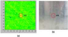
도 4의 (a)는 본 발명에 따른 완전 비접촉 레이저 초음파 기반 3차원 구조물 결함 가시화 장치를 이용하여 검사 대상의 결함을 가시화한 이미지이고, (b)는 검사 대상의 뒷면에 형성된 결함을 나타낸 사진이다.1 is a view showing a first embodiment of a complete non-contact laser ultrasound-based three-dimensional structure defect visualization apparatus according to the present invention.
2 is a view showing a second embodiment of a three-dimensional non-contact laser ultrasound-based defect visualization apparatus according to the present invention.
3 is a view showing a third embodiment of a three-dimensional non-contact laser ultrasound-based defect visualization apparatus according to the present invention.
Figure 4 (a) is an image visualized the defect of the inspection object using a non-contact laser ultrasound-based three-dimensional structure defect visualization device according to the present invention, (b) is a photograph showing a defect formed on the back of the inspection object. .
이하, 본 발명에 따른 완전 비접촉 레이저 초음파 기반 3차원 구조물 결함 가시화 장치 및 방법의 바람직한 실시예를 첨부한 도면들에 의거하여 상세히 설명한다. 참고로, 본 명세서 및 청구범위에 사용된 용어와 단어는 통상적이거나 사전적인 의미로 한정해서 해석되어서는 아니되며, 발명자는 그 자신의 발명을 가장 최선의 방법으로 설명하기 위해 용어의 개념을 적절하게 정의할 수 있다는 원칙에 입각하여 본 발명의 기술적 사상에 부합하는 의미와 개념으로 해석해야만 한다. 또한, 본 명세서에 기재된 실시예와 도면에 도시된 구성은 본 발명의 가장 바람직한 일 실시예에 불과할 뿐이고, 본 발명의 기술적 사상을 모두 대변하는 것은 아니므로 본 출원시점에 있어서 이들을 대체할 수 있는 다양한 균등물과 변형예들이 있을 수 있음을 이해하여야 한다.DETAILED DESCRIPTION OF THE PREFERRED EMBODIMENTS Hereinafter, preferred embodiments of a non-contact laser ultrasound-based 3D structure defect visualization apparatus and method according to the present invention will be described in detail with reference to the accompanying drawings. For reference, terms and words used in the present specification and claims should not be construed as being limited to the ordinary or dictionary meanings, and the inventors should properly explain the concept of terms in order to explain their own invention in the best way. Based on the principle that can be defined, it should be interpreted as meaning and concept corresponding to the technical idea of the present invention. In addition, the embodiments described in the specification and the drawings shown in the drawings are only the most preferred embodiment of the present invention, and do not represent all of the technical spirit of the present invention various modifications that can be replaced at the time of the present application It should be understood that there may be equivalents and variations.
도 1은 본 발명에 따른 완전 비접촉 레이저 초음파 기반 3차원 구조물 결함 가시화 장치의 제1실시예를 나타낸 도면이다.1 is a view showing a first embodiment of a complete non-contact laser ultrasound-based three-dimensional structure defect visualization apparatus according to the present invention.
본 발명의 제1실시예에 따른 완전 비접촉 레이저 초음파 기반 3차원 구조물 결함 가시화 장치는, 도 1에 도시된 바와 같이 레이저빔 조사부(10), 초음파 측정부(20), 레이저빔 조절부(30), 제어부(40)를 포함하여 이루어진다.As shown in FIG. 1, the fully non-contact laser ultrasound-based 3D structure defect visualization apparatus according to the first embodiment of the present invention may include a
레이저빔 조사부(10)는 간헐적으로 제1레이저빔을 검사대상(S)에 조사하여 검사대상(S)에 열팽창이 일어나 초음파를 생성하도록 하는 것으로서, 제1레이저빔은 532 ㎚ 또는 1064 ㎚의 파장을 가진다.The
초음파 측정부(20)는 레이저빔 조사부(10)에 의해 검사대상(S)에 발생된 초음파를 검출하도록 제1레이저빔과 파장이 다른 제2레이저빔을 검사대상(S)에 지속적으로 조사하는 것으로서, 제2레이저빔은 예를 들면 633 ㎚의 파장을 가진다.The
이러한 상기 초음파 측정부(20)는 레이저 도플러 진동계(LDV, laser doppler vibrometer)인 것이 바람직하다.The
레이저빔 조절부(30)는 제1레이저빔과 제2레이저빔을 각각 전달받아 반사하여 검사대상(S)에 위치하도록 조절하는 것으로서, 레이저빔 조사부(10)에서 조사되는 제1레이저빔이 반사되는 제1반사 거울(31)과, 제1반사 거울(31)로부터 반사된 제1레이저빔이 반사되고 초음파 측정부(20)에서 조사되는 제2레이저빔이 통과되는 색 선별 거울(32)과, 색 선별 거울(32)로부터 반사된 제1레이저빔이 반사되어 검사대상(S)에 조사되도록 하고 색 선별 거울(32)을 통과한 제2레이저빔이 반사되어 검사대상(S)에 조사되도록 하는 제2반사 거울(33a)이 부착된 갈바노미터(galvano-meter)로 이루어진 스캐너(33)로 이루어진다.The
색 선별 거울(dichroic mirror)(32)은 박막에 의한 빛의 간섭을 이용하여 가시광의 특정한 파장 영역의 빛 만을 반사하고 나머지 파장 영역의 빛을 투과하는 거울로서, 유리면에 진공 증착으로 높은 굴절률과 낮은 굴절률의 두께를 가진 박막을 번갈아 포개어 붙이는 형태로 제조된다.The
이와 같이 검사대상(S)에서 초음파를 검출한 제2레이저빔은 스캐너(33)의 제2반사 거울(33a)에 의해 반사되어 색 선별 거울(32)을 통과한 다음 초음파 측정부(20)로 전달된다.As described above, the second laser beam that detects the ultrasonic wave from the inspection object S is reflected by the
제어부(40)는 레이저빔 조사부(10)를 제어하는 제1제어기(41)와, 초음파 측정부(20)를 제어하는 제2제어기(42)와, 제1제어기(41) 및 제2제어기(42)와 신호를 주고받아 신호를 처리하는 신호처리기(43)와, 초음파 측정부(20)로부터 측정된 신호를 전달받아 검사대상(S)의 결함을 가시화하여 영상처리하는 영상표시기(44)를 포함하여 이루어진다.The
도 2는 본 발명에 따른 완전 비접촉 레이저 초음파 기반 3차원 구조물 결함 가시화 장치의 제2실시예를 나타낸 도면이다.2 is a view showing a second embodiment of a three-dimensional non-contact laser ultrasound-based three-dimensional structure defect visualization apparatus according to the present invention.
본 발명의 제2실시예에 따른 완전 비접촉 레이저 초음파 기반 3차원 구조물 결함 가시화 장치는, 도 2에 도시된 바와 같이 전술한 제1실시예에서의 레이저빔 조사부(10), 초음파 측정부(20), 레이저빔 조절부(30), 제어부(40) 외에 복수의 콜리메이터(collimator)(M1, M2, M3, M4), 복수의 광케이블(C1, C2) 및 다관절 로봇(50)을 더 포함한다.In the non-contact laser ultrasound-based three-dimensional structure defect visualization apparatus according to the second embodiment of the present invention, as shown in FIG. 2, the laser
콜리메이터는 시준기라고도 하며, 입사 광선이나 입사 입자의 줄기를 평행하게 만들어주는 장치이다.Collimators, also known as collimators, are devices that make the beams of incident light or incident particles parallel.
구체적으로, 레이저빔 조사부(10)에서 제1레이저빔이 조사되는 부분에는 제1콜리메이터(M1)가 설치되고, 레이저빔 조사부(10)로부터 조사된 제1레이저빔이 제1반사 거울(31)에 도달하기 전에 위치한 레이저빔 조절부(30)에는 제2콜리메이터(M2)가 설치되며, 제1콜리메이터(M1)와 제2콜리메이터(M2)는 제1광케이블(C1)로 연결된다.Specifically, a first collimator M1 is installed at a portion of the
또한, 검사대상(S)에서 초음파를 검출한 제2레이저빔이 스캐너(33)의 제2반사 거울(33a)에 의해 반사되어 색 선별 거울(32)을 통과한 부분에 위치한 레이저빔 조절부(30)에는 제3콜리메이터(M3)가 설치되며, 제3콜리메이터(M3)를 통과한 제2레이저빔이 전달되는 초음파 측정부(20)에는 제4콜리메이터(M4)가 설치되고, 제3콜리메이터(M3)와 제4콜리메이터(M4)는 제2광케이블(C2)로 연결된다.In addition, the laser beam control unit positioned at the portion where the second laser beam detected by the ultrasonic wave in the inspection target S is reflected by the
이러한 제1광케이블(C1) 및 제2광케이블(C2)은 전기 신호를 광선 신호로 바꾸어 유리섬유를 통해 전달하는 케이블로서, 광섬유 케이블이라고도 한다.The first optical cable (C1) and the second optical cable (C2) is a cable for converting an electrical signal into a light signal and transmitted through the glass fiber, also called an optical fiber cable.
아울러, 레이저빔 조절부(30)는 다관절(51, 52, 53)로 이루어진 로봇(50)에 연결되고, 로봇(50)은 제어부(40)의 제어신호에 의해 위치조절이 이루어진다.In addition, the laser
도 3은 본 발명에 따른 완전 비접촉 레이저 초음파 기반 3차원 구조물 결함 가시화 장치의 제3실시예를 나타낸 도면이다.3 is a view showing a third embodiment of a three-dimensional non-contact laser ultrasound-based defect visualization apparatus according to the present invention.
본 발명의 제3실시예에 따른 완전 비접촉 레이저 초음파 기반 3차원 구조물 결함 가시화 장치는, 도 3에 도시된 바와 같이 전술한 제1실시예에서의 레이저빔 조사부(10), 초음파 측정부(20), 레이저빔 조절부(30), 제어부(40) 외에 다관절 로봇(50)을 더 포함한다.In the non-contact laser ultrasound-based three-dimensional structure defect visualization apparatus according to the third embodiment of the present invention, as shown in FIG. 3, the
이때, 레이저빔 조사부(10)와 초음파 측정부(20)는 소형으로 이루어져 레이저빔 조절부(30)에 일체로 마련되어 모듈화된다.At this time, the
이에 따라, 레이저빔 조사부(10)와 초음파 측정부(20)가 일체로 모듈화되어 이루어진 레이저빔 조절부(30)는 다관절로 이루어진 로봇(50)에 연결되고, 로봇(50)은 제어부(40)의 제어신호에 의해 위치조절이 이루어진다.Accordingly, the laser
도 4의 (a)는 본 발명에 따른 완전 비접촉 레이저 초음파 기반 3차원 구조물 결함 가시화 장치를 이용하여 검사 대상의 결함을 가시화한 이미지이고, (b)는 검사 대상의 뒷면에 형성된 결함을 나타낸 사진이다.Figure 4 (a) is a visualized image of the defect of the inspection object using a non-contact laser ultrasound-based three-dimensional structure defect visualization device according to the present invention, (b) is a photograph showing a defect formed on the back of the inspection object. .
본 발명에 따른 완전 비접촉 레이저 초음파 기반 3차원 구조물 결함 가시화 방법은, 도 1 내지 도 3에 도시된 바와 같이 레이저빔 조사부(10)에서 간헐적으로 제1레이저빔을 검사대상(S)에 조사하여 검사대상(S)에 열팽창이 일어나 초음파를 생성하도록 하는 제1단계; 초음파 측정부(20)에서 초음파를 검출하도록 제1레이저빔과 파장이 다른 제2레이저빔을 검사대상(S)에 지속적으로 조사하는 제2단계; 제1레이저빔이 레이저빔 조절부(30)의 제1반사 거울(31)에 의해 반사되고, 제1반사 거울(31)로부터 반사된 제1레이저빔이 레이저빔 조절부(30)의 색 선별 거울(32)에 의해 반사되며, 색 선별 거울(32)로부터 반사된 제1레이저빔이 레이저빔 조절부(30)의 제2반사 거울(33a)이 부착된 갈바노미터로 이루어진 스캐너(33)에 의해 반사되어 검사대상(S)에 조사되도록 하고, 초음파 측정부(20)에서 조사되는 제2레이저빔이 색 선별 거울(32)을 통과하며, 색 선별 거울(32)을 통과한 제2레이저빔이 제2반사 거울(33a)이 부착된 갈바노미터로 이루어진 스캐너(33)에 의해 반사되어 검사대상(S)에 조사되도록 하는 제3단계; 검사대상(S)에서 초음파를 검출한 제2레이저빔이 스캐너(33)의 제2반사 거울(33a)에 의해 반사되어 색 선별 거울(32)을 통과한 다음 초음파 측정부(20)로 전달되는 제4단계; 초음파 측정부(20)로부터 측정된 신호를 전달받아 제어부(40)에서 검사대상(S)의 결함을 가시화하여 도 4의 (a)에 도시된 바와 같이 영상처리하는 제5단계;를 포함한다.In the non-contact laser ultrasound-based 3D structure defect visualization method according to the present invention, as shown in FIGS. 1 to 3, the laser
이때, 레이저빔 조절부(30)는 다관절(51, 52, 53)로 이루어진 로봇(50)에 연결되어 제어부(40)의 제어신호에 의해 로봇(50)을 제어함으로써, 레이저빔 조절부(30)의 위치를 조절하게 된다.At this time, the laser
이상에서 설명한 본 발명은 전술한 실시예 및 첨부된 도면들에 의해 한정되는 것은 아니며, 본 발명의 기술적 사상을 벗어나지 않는 범위 내에서 여러 가지 치환, 변형, 및 변경이 가능함은 본 발명이 속하는 기술분야에서 통상의 지식을 가진 자에게 있어 명백할 것이다.The present invention described above is not limited to the above-described embodiment and the accompanying drawings, and various substitutions, modifications, and changes are possible without departing from the technical spirit of the present invention. It will be apparent to those of ordinary skill in Esau.
10 : 레이저빔 조사부 20 : 초음파 측정부
30 : 레이저빔 조절부 31 : 제1반사 거울
32 : 색 선별 거울 33 : 스캐너
33a : 제2반사 거울 40 : 제어부
50 : 로봇10: laser beam irradiation unit 20: ultrasonic measuring unit
30: laser beam control unit 31: the first reflection mirror
32: color screening mirror 33: scanner
33a: second reflection mirror 40: control unit
50: robot
Claims (8)
Translated fromKorean상기 초음파를 검출하도록 상기 제1레이저빔과 파장이 다른 제2레이저빔을 상기 검사대상에 지속적으로 조사하는 초음파 측정부;
상기 제1레이저빔과 제2레이저빔을 각각 전달받아 반사하여 검사대상에 위치하도록 조절하는 레이저빔 조절부; 및
상기 레이저빔 조사부와 초음파 측정부를 각각 제어하고, 상기 초음파 측정부로부터 측정된 신호를 전달받아 검사대상의 결함을 가시화하여 영상처리하는 제어부;를 포함하고,
상기 레이저빔 조절부는,
상기 레이저빔 조사부에서 조사되는 제1레이저빔이 반사되는 제1반사 거울과, 상기 제1반사 거울로부터 반사된 제1레이저빔이 반사되고 상기 초음파 측정부에서 조사되는 제2레이저빔이 통과되는 색 선별 거울과, 상기 색 선별 거울로부터 반사된 제1레이저빔이 반사되어 검사대상에 조사되도록 하고 상기 색 선별 거울을 통과한 제2레이저빔이 반사되어 상기 검사대상에 조사되도록 하는 제2반사 거울이 부착된 갈바노미터로 이루어진 스캐너로 이루어지는 것을 특징으로 하는 완전 비접촉 레이저 초음파 기반 3차원 구조물 결함 가시화 장치.
A laser beam irradiator intermittently irradiating the first laser beam to the inspection object to generate ultrasonic waves by thermal expansion of the inspection object;
An ultrasonic measuring unit continuously irradiating the inspection object with a second laser beam having a different wavelength from the first laser beam to detect the ultrasonic wave;
A laser beam adjusting unit which receives the first laser beam and the second laser beam, respectively, and reflects the laser beams so as to be positioned on an inspection object; And
And a controller for controlling the laser beam irradiator and the ultrasonic measuring unit, respectively, and receiving a signal measured by the ultrasonic measuring unit to visualize and process an image of a defect of an inspection object.
The laser beam control unit,
The first reflecting mirror reflects the first laser beam irradiated from the laser beam irradiation unit, and the color through which the first laser beam reflected from the first reflecting mirror is reflected and the second laser beam irradiated from the ultrasonic measuring unit passes. A screening mirror and a second reflecting mirror reflecting the first laser beam reflected from the color screening mirror to be irradiated to the inspection object and reflecting the second laser beam passing through the color screening mirror to be irradiated to the inspection object; Fully non-contact laser ultrasound-based three-dimensional structure defect visualization device comprising a scanner consisting of an attached galvanometer.
상기 검사대상에서 초음파를 검출한 제2레이저빔은 상기 스캐너의 제2반사 거울에 의해 반사되어 상기 색 선별 거울을 통과한 다음 상기 초음파 측정부로 전달되는 것을 특징으로 하는 완전 비접촉 레이저 초음파 기반 3차원 구조물 결함 가시화 장치.
The method according to claim 1,
The second laser beam that detects the ultrasonic wave from the inspection object is reflected by the second reflection mirror of the scanner and passes through the color screening mirror and then transmitted to the ultrasonic measuring unit. Visualization device.
상기 레이저빔 조사부에서 제1레이저빔이 조사되는 부분에는 제1콜리메이터가 설치되고, 상기 레이저빔 조사부로부터 조사된 제1레이저빔이 제1반사 거울에 도달하기 전에 위치한 레이저빔 조절부에는 제2콜리메이터가 설치되며, 상기 제1콜리메이터와 제2콜리메이터는 제1광케이블로 연결되고,
상기 검사대상에서 초음파를 검출한 제2레이저빔이 상기 스캐너의 제2반사 거울에 의해 반사되어 상기 색 선별 거울을 통과한 부분에 위치한 상기 레이저빔 조절부에는 제3콜리메이터가 설치되며, 상기 제3콜리메이터를 통과한 제2레이저빔이 전달되는 초음파 측정부에는 제4콜리메이터가 설치되고, 상기 제3콜리메이터와 제4콜리메이터는 제2광케이블로 연결되는 것을 특징으로 하는 완전 비접촉 레이저 초음파 기반 3차원 구조물 결함 가시화 장치.
The method according to claim 2,
A first collimator is installed at a portion of the laser beam irradiator where the first laser beam is irradiated, and a second collimator is disposed at the laser beam control unit positioned before the first laser beam irradiated from the laser beam irradiator reaches the first reflection mirror. Is installed, the first collimator and the second collimator is connected by a first optical cable,
A third collimator is installed in the laser beam control unit positioned at a portion where the second laser beam that detects the ultrasonic wave from the inspection object is reflected by the second reflection mirror of the scanner and passes through the color selection mirror, and the third collimator The fourth collimator is installed in the ultrasonic measuring unit for transmitting the second laser beam passing through the third collimator, and the third collimator and the fourth collimator are connected by a second optical cable. Device.
상기 레이저빔 조사부와 초음파 측정부는 레이저빔 조절부에 일체로 마련되어 모듈화된 것을 특징으로 하는 완전 비접촉 레이저 초음파 기반 3차원 구조물 결함 가시화 장치.
The method according to claim 1,
And the laser beam irradiator and the ultrasonic measuring unit are integrally provided and modularized in a laser beam control unit.
상기 레이저빔 조절부는 다관절로 이루어진 로봇에 연결되고, 상기 로봇은 상기 제어부의 제어신호에 의해 위치조절이 이루어지는 것을 특징으로 하는 완전 비접촉 레이저 초음파 기반 3차원 구조물 결함 가시화 장치.
The method according to any one of claims 1 to 4,
The laser beam control unit is connected to a robot consisting of a multi-joint, the robot is a non-contact laser ultrasound-based three-dimensional structure defect visualization device, characterized in that the position is adjusted by the control signal of the controller.
상기 초음파 측정부는 레이저 도플러 진동계(LDV, laser doppler vibrometer)인 것을 특징으로 하는 완전 비접촉 레이저 초음파 기반 3차원 구조물 결함 가시화 장치.
The method according to any one of claims 1 to 4,
And the ultrasonic measuring unit is a laser doppler vibrometer (LDV).
초음파 측정부에서 상기 초음파를 검출하도록 상기 제1레이저빔과 파장이 다른 제2레이저빔을 상기 검사대상에 지속적으로 조사하는 제2단계;
상기 제1레이저빔이 레이저빔 조절부의 제1반사 거울에 의해 반사되고, 상기 제1반사 거울로부터 반사된 제1레이저빔이 레이저빔 조절부의 색 선별 거울에 의해 반사되며, 상기 색 선별 거울로부터 반사된 제1레이저빔이 레이저빔 조절부의 제2반사 거울이 부착된 갈바노미터로 이루어진 스캐너에 의해 반사되어 검사대상에 조사되도록 하고, 상기 초음파 측정부에서 조사되는 제2레이저빔이 상기 색 선별 거울을 통과하며, 상기 색 선별 거울을 통과한 제2레이저빔이 제2반사 거울이 부착된 갈바노미터로 이루어진 스캐너에 의해 반사되어 상기 검사대상에 조사되도록 하는 제3단계;
상기 검사대상에서 초음파를 검출한 제2레이저빔이 상기 스캐너의 제2반사 거울에 의해 반사되어 상기 색 선별 거울을 통과한 다음 상기 초음파 측정부로 전달되는 제4단계;
상기 초음파 측정부로부터 측정된 신호를 전달받아 제어부에서 검사대상의 결함을 가시화하여 영상처리하는 제5단계;를 포함하는 것을 특징으로 하는 완전 비접촉 레이저 초음파 기반 3차원 구조물 결함 가시화 방법.
A first step of intermittently irradiating a first laser beam to an inspection object by a laser beam irradiation unit to generate thermal ultrasonic waves by thermal expansion of the inspection object;
A second step of continuously irradiating the inspection object with a second laser beam having a different wavelength from the first laser beam to detect the ultrasonic wave by an ultrasonic measuring unit;
The first laser beam is reflected by the first reflection mirror of the laser beam adjustment unit, the first laser beam reflected from the first reflection mirror is reflected by the color separation mirror of the laser beam adjustment unit, and reflected from the color separation mirror The first laser beam is reflected by a scanner made of a galvanometer with a second reflecting mirror of a laser beam adjusting unit to be irradiated to the inspection object, and the second laser beam irradiated from the ultrasonic measuring unit is the color selection mirror. A third step through which the second laser beam passing through the color selection mirror is reflected by a scanner made of a galvanometer having a second reflection mirror attached thereto and irradiated onto the inspection object;
A fourth step of transmitting the second laser beam that detects the ultrasonic wave from the inspection object by the second reflection mirror of the scanner, passing through the color selection mirror, and then passing to the ultrasonic measuring unit;
And a fifth step of receiving a signal measured by the ultrasonic measuring unit to visualize and process an image of a defect of an inspection object in a control unit. 3.
상기 레이저빔 조절부는 다관절로 이루어진 로봇에 연결되어 상기 제어부의 제어신호에 의해 상기 로봇을 제어함으로써, 상기 레이저빔 조절부의 위치를 조절하는 것을 특징으로 하는 완전 비접촉 레이저 초음파 기반 3차원 구조물 결함 가시화 방법.The method according to claim 7,
The laser beam control unit is connected to a robot consisting of a multi-joint to control the robot by a control signal of the control unit, to control the position of the laser beam control unit, characterized in that the complete non-contact laser ultrasound-based three-dimensional structure defect visualization method .
Priority Applications (1)
| Application Number | Priority Date | Filing Date | Title |
|---|---|---|---|
| KR1020180092224AKR102104124B1 (en) | 2018-08-08 | 2018-08-08 | Device for flaw visualization of the 3d structures based on fully non-contact laser ultrasonic wave imaging process and the method for the same |
Applications Claiming Priority (1)
| Application Number | Priority Date | Filing Date | Title |
|---|---|---|---|
| KR1020180092224AKR102104124B1 (en) | 2018-08-08 | 2018-08-08 | Device for flaw visualization of the 3d structures based on fully non-contact laser ultrasonic wave imaging process and the method for the same |
Publications (2)
| Publication Number | Publication Date |
|---|---|
| KR20200017066Atrue KR20200017066A (en) | 2020-02-18 |
| KR102104124B1 KR102104124B1 (en) | 2020-04-23 |
Family
ID=69638609
Family Applications (1)
| Application Number | Title | Priority Date | Filing Date |
|---|---|---|---|
| KR1020180092224AActiveKR102104124B1 (en) | 2018-08-08 | 2018-08-08 | Device for flaw visualization of the 3d structures based on fully non-contact laser ultrasonic wave imaging process and the method for the same |
Country Status (1)
| Country | Link |
|---|---|
| KR (1) | KR102104124B1 (en) |
Cited By (4)
| Publication number | Priority date | Publication date | Assignee | Title |
|---|---|---|---|---|
| CN111175233A (en)* | 2020-03-05 | 2020-05-19 | 南京光声超构材料研究院有限公司 | Laser ultrasonic detection method and system for laser precision spot welding quality |
| KR102285477B1 (en)* | 2020-10-26 | 2021-08-03 | 이현철 | Apparatus and Method for Noncontact and Non Destructive Test of Defects Inside Metal using Photoacoustic Imaging for After Induction Hardening |
| US12111234B2 (en) | 2021-08-19 | 2024-10-08 | Samsung Electro-Mechanics Co., Ltd. | Device and method of detecting defective electronic component |
| CN120232959A (en)* | 2025-05-30 | 2025-07-01 | 深圳禾思众成科技有限公司 | An automatic identification method of HTCC ceramic defects based on industrial model assistance |
Families Citing this family (2)
| Publication number | Priority date | Publication date | Assignee | Title |
|---|---|---|---|---|
| KR102835858B1 (en)* | 2023-08-18 | 2025-07-18 | 국방과학연구소 | Laser targeting and active image acquisition optical system |
| KR20250037299A (en) | 2023-09-08 | 2025-03-17 | 한국원자력연구원 | Laser induced phased array ultrasonic inspection system and method thereof |
Citations (7)
| Publication number | Priority date | Publication date | Assignee | Title |
|---|---|---|---|---|
| JP2008058029A (en)* | 2006-08-29 | 2008-03-13 | Nagoya Institute Of Technology | Ultrasonic analysis system |
| KR20090049351A (en)* | 2007-11-13 | 2009-05-18 | 한국원자력연구원 | High efficiency laser ultrasonic defect inspection device and method using polarization |
| KR101429348B1 (en) | 2012-09-05 | 2014-08-13 | 한국원자력연구원 | Nondestructive noncontact visual inspection apparatus and method for the internal crack detection of a specimen |
| WO2016171063A1 (en)* | 2015-04-23 | 2016-10-27 | 横河電機株式会社 | Photoacoustic wave detecting device, and photoacoustic imaging device |
| KR20160139915A (en)* | 2015-05-29 | 2016-12-07 | 한국과학기술원 | Apparatus and method for full-field pulse-echo laser ultrasonic propagation imaging |
| KR101694812B1 (en)* | 2015-08-28 | 2017-01-23 | 한국과학기술원 | Method and Apparatus for Noncontactly Detecting Defect via Multipoint concurrent Laser Excitation |
| KR101749602B1 (en)* | 2016-04-05 | 2017-06-21 | 포항공과대학교 산학협력단 | Optical resolution photoacoustic microscopy using non-conductive fluid, and photoacoustic image acquisition system and method using the same |
- 2018
- 2018-08-08KRKR1020180092224Apatent/KR102104124B1/enactiveActive
Patent Citations (7)
| Publication number | Priority date | Publication date | Assignee | Title |
|---|---|---|---|---|
| JP2008058029A (en)* | 2006-08-29 | 2008-03-13 | Nagoya Institute Of Technology | Ultrasonic analysis system |
| KR20090049351A (en)* | 2007-11-13 | 2009-05-18 | 한국원자력연구원 | High efficiency laser ultrasonic defect inspection device and method using polarization |
| KR101429348B1 (en) | 2012-09-05 | 2014-08-13 | 한국원자력연구원 | Nondestructive noncontact visual inspection apparatus and method for the internal crack detection of a specimen |
| WO2016171063A1 (en)* | 2015-04-23 | 2016-10-27 | 横河電機株式会社 | Photoacoustic wave detecting device, and photoacoustic imaging device |
| KR20160139915A (en)* | 2015-05-29 | 2016-12-07 | 한국과학기술원 | Apparatus and method for full-field pulse-echo laser ultrasonic propagation imaging |
| KR101694812B1 (en)* | 2015-08-28 | 2017-01-23 | 한국과학기술원 | Method and Apparatus for Noncontactly Detecting Defect via Multipoint concurrent Laser Excitation |
| KR101749602B1 (en)* | 2016-04-05 | 2017-06-21 | 포항공과대학교 산학협력단 | Optical resolution photoacoustic microscopy using non-conductive fluid, and photoacoustic image acquisition system and method using the same |
Cited By (5)
| Publication number | Priority date | Publication date | Assignee | Title |
|---|---|---|---|---|
| CN111175233A (en)* | 2020-03-05 | 2020-05-19 | 南京光声超构材料研究院有限公司 | Laser ultrasonic detection method and system for laser precision spot welding quality |
| KR102285477B1 (en)* | 2020-10-26 | 2021-08-03 | 이현철 | Apparatus and Method for Noncontact and Non Destructive Test of Defects Inside Metal using Photoacoustic Imaging for After Induction Hardening |
| WO2022092505A1 (en)* | 2020-10-26 | 2022-05-05 | 이현철 | Apparatus and method for non-destructive inspection of defects inside high-frequency heat-treated metal using non-contact photoacoustic images |
| US12111234B2 (en) | 2021-08-19 | 2024-10-08 | Samsung Electro-Mechanics Co., Ltd. | Device and method of detecting defective electronic component |
| CN120232959A (en)* | 2025-05-30 | 2025-07-01 | 深圳禾思众成科技有限公司 | An automatic identification method of HTCC ceramic defects based on industrial model assistance |
Also Published As
| Publication number | Publication date |
|---|---|
| KR102104124B1 (en) | 2020-04-23 |
Similar Documents
| Publication | Publication Date | Title |
|---|---|---|
| KR102104124B1 (en) | Device for flaw visualization of the 3d structures based on fully non-contact laser ultrasonic wave imaging process and the method for the same | |
| KR102109325B1 (en) | Apparatus for nondestructive and noncontact inspection of composite structures based on terahertz wave and the method for the same | |
| US7650789B2 (en) | Method and apparatus for examining the interior material of an object, such as a pipeline or a human body from a surface of the object using ultrasound | |
| CN107024542B (en) | Airborne ultrasonic testing system for test object | |
| US8616062B2 (en) | Ultrasonic inspection system and ultrasonic inspection method | |
| KR101746922B1 (en) | Apparatus and method for full-field pulse-echo laser ultrasonic propagation imaging | |
| CN106077956A (en) | A kind of remove thin film or the laser processing of coating and equipment | |
| KR20170101834A (en) | Inspection of structures | |
| US11692810B2 (en) | Photoacoustic excitation sensing enhanced by cross-correlated unfocused speckle images | |
| KR102328542B1 (en) | storage tank defect measuring apparatus and measuring method thereof | |
| KR20120051507A (en) | Noncontact imaging device and method for nondestructive testing | |
| US20060215174A1 (en) | System and method to inspect components having non-parallel surfaces | |
| KR101444078B1 (en) | Nondestructive Testing Apparatus and Method for Penetration Nozzle of Control Rod Drive Mechanism of Reactor Vessel Head | |
| KR101057586B1 (en) | Malformed Ultrasonic Wave Imaging Device | |
| Bagheri et al. | Guided ultrasonic wave imaging for immersed plates based on wavelet transform and probabilistic analysis | |
| KR101701409B1 (en) | Apparatus and method for generating high resolution and high sensitivie images using terahertz electromagnetic waves | |
| JP5959677B2 (en) | Ultrasonic flaw detection apparatus and ultrasonic flaw detection method | |
| JP2012137464A (en) | Ultrasonic flaw detection system and ultrasonic flaw detection method | |
| CN114018827A (en) | Laser ultrasonic nondestructive testing equipment and method based on shearing speckle interference | |
| KR101312321B1 (en) | Nondestructive crack detecting apparatus for a nuclear fuel plate | |
| US20130088707A1 (en) | Method and system for crack detection | |
| KR102493099B1 (en) | sleeve still surface temperature measuring apparatus and measuring method thereof | |
| EP4439059A1 (en) | Multiple channel laser ultrasonic system | |
| KR101952902B1 (en) | An Optical Scanning System Using Refraction Of Light | |
| US9739592B2 (en) | Multiple beam path laser optical system using multiple beam reflector |
Legal Events
| Date | Code | Title | Description |
|---|---|---|---|
| PA0109 | Patent application | St.27 status event code:A-0-1-A10-A12-nap-PA0109 | |
| PA0201 | Request for examination | St.27 status event code:A-1-2-D10-D11-exm-PA0201 | |
| R18-X000 | Changes to party contact information recorded | St.27 status event code:A-3-3-R10-R18-oth-X000 | |
| D13-X000 | Search requested | St.27 status event code:A-1-2-D10-D13-srh-X000 | |
| PN2301 | Change of applicant | St.27 status event code:A-3-3-R10-R13-asn-PN2301 St.27 status event code:A-3-3-R10-R11-asn-PN2301 | |
| D14-X000 | Search report completed | St.27 status event code:A-1-2-D10-D14-srh-X000 | |
| PE0902 | Notice of grounds for rejection | St.27 status event code:A-1-2-D10-D21-exm-PE0902 | |
| R18-X000 | Changes to party contact information recorded | St.27 status event code:A-3-3-R10-R18-oth-X000 | |
| P11-X000 | Amendment of application requested | St.27 status event code:A-2-2-P10-P11-nap-X000 | |
| P13-X000 | Application amended | St.27 status event code:A-2-2-P10-P13-nap-X000 | |
| PG1501 | Laying open of application | St.27 status event code:A-1-1-Q10-Q12-nap-PG1501 | |
| E701 | Decision to grant or registration of patent right | ||
| PE0701 | Decision of registration | St.27 status event code:A-1-2-D10-D22-exm-PE0701 | |
| PR0701 | Registration of establishment | St.27 status event code:A-2-4-F10-F11-exm-PR0701 | |
| PR1002 | Payment of registration fee | St.27 status event code:A-2-2-U10-U11-oth-PR1002 Fee payment year number:1 | |
| PG1601 | Publication of registration | St.27 status event code:A-4-4-Q10-Q13-nap-PG1601 | |
| PN2301 | Change of applicant | St.27 status event code:A-5-5-R10-R13-asn-PN2301 St.27 status event code:A-5-5-R10-R11-asn-PN2301 | |
| PN2301 | Change of applicant | St.27 status event code:A-5-5-R10-R13-asn-PN2301 St.27 status event code:A-5-5-R10-R11-asn-PN2301 | |
| R18-X000 | Changes to party contact information recorded | St.27 status event code:A-5-5-R10-R18-oth-X000 | |
| PR1001 | Payment of annual fee | St.27 status event code:A-4-4-U10-U11-oth-PR1001 Fee payment year number:4 | |
| R18-X000 | Changes to party contact information recorded | St.27 status event code:A-5-5-R10-R18-oth-X000 | |
| PR1001 | Payment of annual fee | St.27 status event code:A-4-4-U10-U11-oth-PR1001 Fee payment year number:5 | |
| PR1001 | Payment of annual fee | St.27 status event code:A-4-4-U10-U11-oth-PR1001 Fee payment year number:6 |