KR20200014993A - System for reducing membrane fouling and reducing method using thereof - Google Patents
System for reducing membrane fouling and reducing method using thereofDownload PDFInfo
- Publication number
- KR20200014993A KR20200014993AKR1020180090198AKR20180090198AKR20200014993AKR 20200014993 AKR20200014993 AKR 20200014993AKR 1020180090198 AKR1020180090198 AKR 1020180090198AKR 20180090198 AKR20180090198 AKR 20180090198AKR 20200014993 AKR20200014993 AKR 20200014993A
- Authority
- KR
- South Korea
- Prior art keywords
- hollow fiber
- membrane
- fiber membrane
- frequency
- reduction system
- Prior art date
- Legal status (The legal status is an assumption and is not a legal conclusion. Google has not performed a legal analysis and makes no representation as to the accuracy of the status listed.)
- Granted
Links
Images


Classifications
- B—PERFORMING OPERATIONS; TRANSPORTING
- B01—PHYSICAL OR CHEMICAL PROCESSES OR APPARATUS IN GENERAL
- B01D—SEPARATION
- B01D65/00—Accessories or auxiliary operations, in general, for separation processes or apparatus using semi-permeable membranes
- B01D65/08—Prevention of membrane fouling or of concentration polarisation
- B—PERFORMING OPERATIONS; TRANSPORTING
- B01—PHYSICAL OR CHEMICAL PROCESSES OR APPARATUS IN GENERAL
- B01D—SEPARATION
- B01D65/00—Accessories or auxiliary operations, in general, for separation processes or apparatus using semi-permeable membranes
- B01D65/02—Membrane cleaning or sterilisation ; Membrane regeneration
- B—PERFORMING OPERATIONS; TRANSPORTING
- B01—PHYSICAL OR CHEMICAL PROCESSES OR APPARATUS IN GENERAL
- B01D—SEPARATION
- B01D63/00—Apparatus in general for separation processes using semi-permeable membranes
- B01D63/02—Hollow fibre modules
- B—PERFORMING OPERATIONS; TRANSPORTING
- B01—PHYSICAL OR CHEMICAL PROCESSES OR APPARATUS IN GENERAL
- B01D—SEPARATION
- B01D69/00—Semi-permeable membranes for separation processes or apparatus characterised by their form, structure or properties; Manufacturing processes specially adapted therefor
- B01D69/08—Hollow fibre membranes
- B—PERFORMING OPERATIONS; TRANSPORTING
- B01—PHYSICAL OR CHEMICAL PROCESSES OR APPARATUS IN GENERAL
- B01D—SEPARATION
- B01D71/00—Semi-permeable membranes for separation processes or apparatus characterised by the material; Manufacturing processes specially adapted therefor
- B01D71/06—Organic material
- B01D71/30—Polyalkenyl halides
- B01D71/32—Polyalkenyl halides containing fluorine atoms
- B01D71/34—Polyvinylidene fluoride
- B—PERFORMING OPERATIONS; TRANSPORTING
- B01—PHYSICAL OR CHEMICAL PROCESSES OR APPARATUS IN GENERAL
- B01D—SEPARATION
- B01D2321/00—Details relating to membrane cleaning, regeneration, sterilization or to the prevention of fouling
- B01D2321/20—By influencing the flow
- B01D2321/2033—By influencing the flow dynamically
- B01D2321/2058—By influencing the flow dynamically by vibration of the membrane, e.g. with an actuator
Landscapes
- Chemical & Material Sciences (AREA)
- Chemical Kinetics & Catalysis (AREA)
- Separation Using Semi-Permeable Membranes (AREA)
Abstract
Translated fromKoreanDescription
Translated fromKorean본 발명은 중공사막 자체의 공진을 이용하여 막 파울링을 저감하는 시스템 및 이를 이용한 막 파울링 저감 방법에 관한 것이다.The present invention relates to a system for reducing membrane fouling using resonance of a hollow fiber membrane itself, and a method for reducing membrane fouling using the same.
고분자 분리막은 기술의 진보와 함께 다양한 분야로의 확대가 이루어지고 있으며, 특히 환경의 중요성이 대두되면서 수처리 분야에서 그 수요가 증가되고 있다. 일례로 중공사막은 표면에 무수히 많은 작은 기공이 뚫려 있고 가운데 공간이 비어있는 가는 섬유로 이루어진 분리막으로, 무균수, 음용수, 초순수 제조 등 정밀 여과분야에서 널리 이용되어 왔으며, 최근 하수처리장에서의 2차, 3차 처리나 정화조에서의 고액 분리, 산업폐수에서의 부유 물질(SS: Suspended Solid) 제거, 하천수의 여과, 공업용수의 여과, 및 수영장 물의 여과 등으로 그 응용 범위가 확대되고 있다.Polymer separators are being expanded to various fields with the advancement of technology, and in particular, the demand for water treatment is increasing due to the importance of environment. Hollow fiber membranes, for example, are membranes made of fine fibers with a myriad of small pores on the surface and empty in the middle. In addition, the application range is being extended to solid-liquid separation in tertiary treatment or septic tanks, removal of suspended solids (SS) from industrial wastewater, filtration of river water, filtration of industrial water, and filtration of pool water.
상기 하수 처리에 사용되는 중공사막 모듈은 구동방식에 따라 침지식(submerged-type) 모듈과 가압식(pressurised-type) 모듈로 나뉘어진다.The hollow fiber membrane module used for the sewage treatment is divided into a submerged-type module and a pressurized-type module according to a driving method.
상기 침지식 모듈은 처리하고자 하는 유체의 탱크에 중공사막 모듈을 직접 침지시키고 중공사막 내부에 음압(negative pressure)을 가하여 유체만을 선택적으로 중공사 내부로 투과시킴으로써 불순물 또는 슬러지 등의 고형 성분을 분리한다. 이러한 침지형 중공사막 모듈은 기존 설비의 탱크를 그대로 적용할 수 있기 때문에 시설비를 절감할 수 있으며, 낮은 압력으로 운전되기 때문에 고압이 필요한 가압형 모듈에 비해 낮은 운전비가 소요되는 장점이 있다.The immersion module directly immerses the hollow fiber membrane module in the tank of the fluid to be treated and applies a negative pressure to the inside of the hollow fiber membrane to selectively penetrate only the fluid into the hollow fiber to separate solid components such as impurities or sludge. . Since the submerged hollow fiber membrane module can be applied to the tank of the existing equipment as it is, it is possible to reduce the cost of the facility, and because it is operated at a low pressure has the advantage of lower operating costs than the pressurized module that requires high pressure.
그러나 오염물질이 중공사막의 외부에 부착하여 미세기공을 막거나 오염물질이 중공사막의 미세기공을 투과하여 중공사막의 내부로 침투하게 되면, 수처리가 진행됨에 따라 중공사막의 투과 성능이 떨어지는 문제점이 발생한다. 따라서 하/폐수 처리시 연속공기폭기, 공기 주입량 증대의 방법 등공기를 통해 막 표면의 오염물질을 제거하고 있다.However, when contaminants adhere to the outside of the hollow fiber membranes to block the micropores, or when the contaminants penetrate the micropores of the hollow fiber membranes and penetrate the inside of the hollow fiber membranes, the permeation performance of the hollow fiber membranes decreases as the water treatment proceeds. Occurs. Therefore, contaminants on the surface of the membrane are removed through the air, such as continuous air aeration and method of increasing the air injection amount during sewage / wastewater treatment.
이와 관련하여, 한국등록특허 제544383호에는 산기관에서 발생된 공기에 의해 중공사분리막 다발을 좌우로 진동하게 하여 중공사분리막의 오염을 최소화하는 산기관 일체형 중공사분리막이 개시되어 있다. 상기 선행기술은 처리수량(flux)이 약 30 LMH로 양호한 처리수량을 나타내지만, 반복된 공기세정으로 인해 중공사막 자체에 손상이 발생할 수 있으며, 산기관 일체형 모듈로 교체시 불편함이 있다.In this regard, Korean Patent No. 544383 discloses an diffuser-integrated hollow fiber separator that minimizes contamination of the hollow fiber separator by vibrating the hollow fiber separator bundles left and right by air generated in the diffuser. Although the prior art shows a good throughput of about 30 LMH of flux, damage to the hollow fiber membrane itself may occur due to repeated air cleaning, and it is inconvenient to replace the diffuser integrated module.
또한, 한국등록특허 제1718161호에는 중공사막 고정용 엔드캡에 공기가 통과하는 채널을 형성하고, 채널의 면적을 상부 쪽으로 갈수록 작아지게 형성함으로써, 역세시 공기 방울이 지나가는 통로를 좁게 하여 공기방울의 압력을 높이는 방법이 개시되어 있다. 그러나 상기 방법의 경우, 분리막 하단부에서는 일정 정도 세척력이 향상되는 효과를 얻을 수 있으나, 분리막 상단부에서는 세척력 향상 효과가 미미하다는 문제점이 있다.In addition, Korean Patent No. 1718161 forms a channel through which air passes through the end cap for fixing the hollow fiber membrane, and forms an area of the channel smaller toward the upper side, thereby narrowing a passage through which air bubbles pass during backwashing, thereby reducing the pressure of the air bubble. A method of raising is disclosed. However, in the case of the method, the lower portion of the separation membrane to obtain a certain degree of the effect of improving the cleaning power, the upper portion of the separator has a problem that the effect of improving the washing power is insignificant.
또한, 한국등록특허 제1726517호에는 유체의 흐름에 따라 분리막 번들을 상하 방향으로 유동시켜 분리막 표면의 오염물질을 제거하는 방법이 개시되어 있다. 그러나 상기 방법의 경우, 원수 유입시에 중공사막 하부 측에 달라붙어 있던 오염물질들이 떨어지면서 일부는 중공사막 상부에 재부착되는 문제점이 발생될 수 있으며, 반복적 구동으로 인해 중공사막이 손상될 수 있다.In addition, Korean Patent No. 1726517 discloses a method of removing contaminants on a surface of a separator by flowing a separator bundle in a vertical direction according to a flow of a fluid. However, in the case of the above method, some contaminants that adhered to the lower side of the hollow fiber membrane during the inflow of raw water may fall and some may be reattached to the upper portion of the hollow fiber membrane, and the hollow fiber membrane may be damaged due to repeated driving. .
이에 막에 부착된 오염물질 제거효율과 더불어 막의 수명을 높일 수 있는 중공사막 모듈의 개발이 절실히 요구되고 있는 실정이다.Therefore, the development of hollow fiber membrane modules that can increase the life of the membrane in addition to the pollutant removal efficiency attached to the membrane is urgently required.
본 발명은 중공사막 자체의 손상이 적고 막의 교체 주기 연장이 가능하여 경제적이고 효율적인 막 파울링을 저감하는 시스템 및 이를 이용한 막 파울링 저감 방법을 제공하는 데 그 목적이 있다.An object of the present invention is to provide a system for reducing the fouling of the hollow fiber membrane itself is possible to extend the replacement cycle of the membrane and economical and efficient membrane fouling and a method for reducing fouling using the same.
또한, 본 발명은 막 표면에 붙어있는 오염물질을 용이하게 제거할 뿐만 아니라, 오염물질의 제거효율도 높은 막 파울링을 저감하는 시스템 및 이를 이용한 막 파울링 저감 방법을 제공하는 데 그 목적이 있다.In addition, an object of the present invention is to provide a system for reducing membrane fouling that has a high efficiency of removing contaminants as well as easily removing contaminants attached to the membrane surface, and a method for reducing membrane fouling using the same. .
또한, 본 발명은 종래 물리 화학적 처리 시 지속적으로 발생되는 비용 및 노동력 등에 대한 문제를 개선할 수 있는 막 파울링 저감 시스템 및 이를 이용한 막 파울링 저감 방법을 제공하는 데 그 목적이 있다.In addition, an object of the present invention is to provide a membrane fouling reduction system and a membrane fouling reduction method using the same that can improve the problems such as the cost and labor continuously generated in the conventional physicochemical treatment.
본 발명은 복수개의 중공사막과, 상기 중공사막의 제1끝단 및 제2끝단을 각각 고정하는 제1 및 제2 고정부재를 포함하는 중공사막 모듈; 상기 중공사막을 고유주파수로 공진시킬 수 있는 가진기; 상기 가진기에 중공사막의 고유주파수를 생성하는 주파수 발생기; 및 상기 주파수 발생기의 출력을 증폭하는 증폭기를 포함하며, 상기 중공사막은 장력이 0.05N/㎡ 이상으로 긴장된 상태인 것을 특징으로 하는 막 파울링 저감 시스템을 제공한다.The present invention provides a hollow fiber membrane module including a plurality of hollow fiber membranes and first and second fixing members for fixing the first and second ends of the hollow fiber membranes, respectively; An exciter capable of resonating the hollow fiber membrane at a natural frequency; A frequency generator for generating a natural frequency of the hollow fiber membrane in the exciter; And an amplifier for amplifying the output of the frequency generator, the hollow fiber membrane provides a membrane fouling reduction system, characterized in that the tension is tensioned at 0.05 N /
또한, 본 발명은 제1끝단 및 제2끝단이 각각 제1 및 제2 고정부재에 고정된 복수개의 중공사막의 고유 주파수를 도출하는 단계; 상기 도출된 중공사막의 고유 주파수를 발생시키는 단계; 상기 도출된 중공사막의 고유 주파수를 발생시키는 단계; 상기 발생된 고유 주파수를 증폭시키는 단계; 및 상기 증폭된 고유 주파수를 진동으로 변환하여 발생시키는 단계; 상기 진동을 제1 및 제2 고정부재에 전달하여 중공사막을 공진하는 단계를 포함하는 것을 특징으로 하는 막 파울링 저감 방법을 제공한다.In addition, the present invention comprises the steps of deriving the natural frequencies of the plurality of hollow fiber membranes the first end and the second end is fixed to the first and the second fixing member, respectively; Generating a natural frequency of the derived hollow fiber membrane; Generating a natural frequency of the derived hollow fiber membrane; Amplifying the generated natural frequency; And converting the amplified natural frequencies into vibrations to generate the vibrations. And transmitting the vibrations to the first and second fixing members to resonate the hollow fiber membranes.
본 발명에 따른 막 파울링 저감 시스템은 중공사막의 고유진동수를 이용하여 공진을 발생시킴으로써 오염물질이 막 표면에서 쉽게 제거될 수 있으므로 장기간 막 투과성능을 유지할 수 있는 효과가 있다.The membrane fouling reduction system according to the present invention has an effect of maintaining membrane permeation performance for a long time because contaminants can be easily removed from the membrane surface by generating resonance using the natural frequency of the hollow fiber membrane.
또한, 본 발명에 따른 막 파울링 저감 시스템은 중공사막의 고유진동수를 이용하여 공진을 발생시킴으로써 중공사막 자체의 손상이 적어 막의 교체 주기 연장이 가능하여 경제적인 이점이 있다.In addition, the membrane fouling reduction system according to the present invention is economical because it is possible to extend the replacement cycle of the membrane is less damage to the hollow fiber membrane by generating a resonance using the natural frequency of the hollow fiber membrane.
또한, 본 발명에 따른 막 파울링 저감 시스템은 적은 구동에너지를 이용하여 강한 진동을 발생시킬 수 있으므로 에너지 소비를 저감할 수 있는 효과가 있다.In addition, the membrane fouling reduction system according to the present invention has the effect of reducing the energy consumption because it can generate a strong vibration using a small drive energy.
또한, 본 발명에 따른 막 파울링 저감 시스템은 종래 물리 화학적 처리 시 지속적으로 발생되는 비용 및 노동력 등에 대한 문제를 개선할 수 있다.In addition, the membrane fouling reduction system according to the present invention can improve the problems such as cost and labor continuously generated in the conventional physicochemical treatment.
도 1은 본 발명에 따른 일례의 막 파울링 저감 시스템의 개략도를 나타낸 것이고,
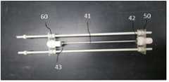
도 2는 본 발명에 따른 일례의 중공사막 모듈을 나타낸 것이고,
도 3은 본 발명의 실험예에 따른 (1)no vibration, (2)aeration, (3)vibration, (4)resonance 조건의 장치 개략도를 나타낸 것이고,
도 4는 본 발명의 실험예에 따른 (1)no vibration, (2)aeration, (3)vibration, (4)resonance 조건에서의 (a)임계 플럭스 및 (b)장시간 운전 실험 효과 데이터를 나타낸 것이다.1 shows a schematic diagram of an example membrane fouling reduction system according to the invention,
Figure 2 shows an example hollow fiber membrane module according to the present invention,
Figure 3 shows the device schematic of (1) no vibration, (2) aeration, (3) vibration, (4) resonance conditions according to the experimental example of the present invention,
4 shows (a) critical flux and (b) long-term driving test effect data under (1) no vibration, (2) aeration, (3) vibration and (4) resonance conditions according to the experimental example of the present invention. .
이하, 본 발명에 따른 바람직한 실시 형태를 첨부된 도면을 참조하여 상세하게 설명한다. 첨부된 도면과 함께 이하에 개시될 상세한 설명은 본 발명의 예시적인 실시형태를 설명하고자 하는 것이며, 본 발명이 실시될 수 있는 유일한 실시형태를 나타내고자 하는 것이 아니다. 이하의 상세한 설명은 본 발명의 완전한 이해를 제공하기 위해서 구체적 세부사항을 포함한다. 그러나, 본 발명이 속하는 기술분야에서 통상의 지식을 가진 자는 본 발명이 이러한 구체적 세부사항 없이도 실시될 수 있음을 안다.Hereinafter, preferred embodiments of the present invention will be described in detail with reference to the accompanying drawings. The detailed description, which will be given below with reference to the accompanying drawings, is intended to explain exemplary embodiments of the present invention and is not intended to represent the only embodiments in which the present invention may be practiced. The following detailed description includes specific details in order to provide a thorough understanding of the present invention. However, one of ordinary skill in the art appreciates that the present invention may be practiced without these specific details.
몇몇 경우, 본 발명의 개념이 모호해지는 것을 피하기 위하여 공지의 구조 및 장치는 생략되거나, 각 구조 및 장치의 핵심기능을 중심으로 한 블록도 형식으로 도시될 수 있다.In some instances, well-known structures and devices may be omitted or shown in block diagram form centering on the core functions of the structures and devices in order to avoid obscuring the concepts of the present invention.
명세서 전체에서, 어떤 부분이 어떤 구성요소를 "포함(comprising 또는 including)"한다고 할 때, 이는 특별히 반대되는 기재가 없는 한 다른 구성요소를 제외하는 것이 아니라 다른 구성요소를 더 포함할 수 있는 것을 의미한다. 또한, 명세서에 기재된 "…부"의 용어는 적어도 하나의 기능이나 동작을 처리하는 단위를 의미한다.Throughout the specification, when a part is said to "comprising" (or including) a component, this means that it may further include other components, except to exclude other components unless otherwise stated. do. In addition, the term "... part" described in the specification means a unit that processes at least one function or operation.
또한, "일(a 또는 an)", "하나(one)", "그(the)" 및 유사 관련어는 본 발명을 기술하는 문맥에 있어서(특히, 이하의 청구항의 문맥에서) 본 명세서에 달리 지시되거나 문맥에 의해 분명하게 반박되지 않는 한, 단수 및 복수 모두를 포함하는 의미로 사용될 수 있다.Also, "a" or "an", "one", "the", and the like shall not be construed herein in the context of describing the present invention (particularly in the context of the following claims). Unless otherwise indicated or clearly contradicted by context, it may be used in the sense including both the singular and the plural.
본 발명의 실시예들을 설명함에 있어서 공지 기능 또는 구성에 대한 구체적인 설명이 본 발명의 요지를 불필요하게 흐릴 수 있다고 판단되는 경우에는 그 상세한 설명을 생략할 것이다. 그리고 후술되는 용어들은 본 발명의 실시예에서의 기능을 고려하여 정의된 용어들로서 이는 사용자, 운용자의 의도 또는 관례 등에 따라 달라질 수 있다. 그러므로 그 정의는 본 명세서 전반에 걸친 내용을 토대로 내려져야 할 것이다.In describing the embodiments of the present invention, if it is determined that a detailed description of a known function or configuration may unnecessarily obscure the gist of the present invention, the detailed description thereof will be omitted. In addition, terms to be described below are terms defined in consideration of functions in the embodiments of the present invention, which may vary according to intentions or customs of users and operators. Therefore, the definition should be made based on the contents throughout the specification.
본 발명의 바람직한 실시예를 첨부된 도면을 참조하여 막 파울링 저감 시스템에 대하여 상세하게 설명하면 다음과 같다,Referring to the preferred embodiment of the present invention with reference to the accompanying drawings, the membrane fouling reduction system in detail as follows,
도 1은 본 발명의 일례에 따른 막 파울링 저감 시스템을 나타낸 것이다,1 shows a membrane fouling reduction system according to an example of the present invention,
본 발명에 따른 막 파울링 저감 시스템은 주파수 발생기(10), 증폭기(20), 가진기(30) 및 중공사막 모듈(40)을 포함한다. 우선, 상기 주파수 발생기(10)에서 발생된 주파수는 증폭기(20)를 통해 증폭되고 가진기(30)에 신호를 전달한다. 상기 가진기(30)는 전달된 주파수에 대응하는 진동을 중공사막 모듈(40)에 전달한다.The membrane fouling reduction system according to the present invention includes a
상기 중공사막 모듈(40)은 복수개의 중공사막(41)과, 상기 중공사막(41)의 제1끝단(42) 및 제2끝단(43)을 각각 고정하는 제1 및 제2 고정부재(50, 60)를 포함한다.The hollow
본 발명은 상기 중공사막 모듈의 진동이 아니라, 중공사막의 고유진동수를 이용하여 공진을 발생시켜 막 파울링을 저감시키는 것에 기술구성상의 특징이 있다.The present invention is characterized in that it is not vibration of the hollow fiber membrane module, but reduces the fouling by generating resonance by using the natural frequency of the hollow fiber membrane.
상기 중공사막(41)은 공진을 효율적으로 발생시키기 위하여, 장력을 0.05 N/m2이상, 구체적으로 0.05 내지 0.5N/m2범위의 장력을 유지하도록 한다. 상기 장력이 0.05 N/m2미만인 경우에는 공진에 의한 중공사막의 진폭(변위)이 커져 중공사막 양 끝단 포팅층에 손상이 발생할 수 있고, 장력이 0.5N/㎡ 이상인 경우 반대로 진폭(변위)이 작아져 분리막 표면의 전단응력이 작아지는 문제가 발생할 수 있다. 상기 중공사막에 인가된 장력 제거후의 발생 변형률이 1%이하인 것이 좋다.The
이러한 상기 중공사막(41)은 당 분야에서 일반적으로 사용되는 것으로 특별히 한정하지는 않으나, 구체적으로 폴리프로필렌(PP), 폴리테트라플루오로에틸렌(PTFE), 폴리불화비닐리덴 (PVDF) 및 폴리에테르술폰/술폰화 폴리에테르술폰(PES/SPES)으로 이루어진 군에서 선택된 소재로 이루어진 것을 사용할 수 있다. 취급의 용이성, 가격 경쟁력, 상용성 및 기계적 강도 등을 고려하면 폴리불화비닐리덴(PVDF) 소재인 것이 바람직하다.The
상기 중공사막(41)의 고유주파수는 막 소재의 선밀도, 길이, 장력 등에 의해 변화된다. 이러한 중공사막(41)은 50 내지 200 Hz의 고유주파수를 발생시키는 것을 사용하는 것이 바람직하다. 상기 중공사막은 50 Hz 미만의 고유주파수를 발생시키는 경우에는 전단응력이 낮아지는 문제가 발생할 수 있으며 200 Hz를 초과하는 경우에는 전단응력이 지나치게 높아져 기계적 내구성이 문제가 발생할 수 있다. 일례로 PVDF 소재, 선밀도 0.427g/m, 길이 15cm, 장력 0.3N/m2인 중공사막의 경우에는 고유주파수가 약 103Hz이며, 상기 고유주파수에 의해 가진기의 출력전류, 주파수 발생기의 주파수 및 증폭기의 출력전압을 결정하게 된다.The natural frequency of the
또한, 본 발명에 따른 중공사막 모듈은 중공사막의 장력을 재긴장이 가능하도록 장력조절 기능이 포함될 수 있다. 상기 장력조절 기능은 장시간 중공사막을 공진할 경우 변하는 장력을 재긴장시키는 것을 의미하며, 중공사분리막 모듈의 고정부재에 장력조절너트를 결합하여 재긴장이 가능하도록 구성될 수 있다.(분리막을 공진시켜 장시간 운전할 경우 분리막의 탄성에 의하여 신장되어(늘어남) 장력이 변하는 문제가 발생하며, 이를 해결하기 위하여 중공사막 모듈 고정부재(60)와 결합된 장력조절 너트를 이용하여 중공사막의 장력을 재 긴장시킬수 있도록 함)In addition, the hollow fiber membrane module according to the present invention may include a tension control function to enable the tension of the hollow fiber membrane. The tension control function means to re-tension the changing tension when resonating the hollow fiber membrane for a long time, it may be configured to enable the re-tension by coupling the tension control nut to the fixing member of the hollow fiber membrane module. In the case of a long time operation, the elasticity of the membrane is extended (stretched), which causes a problem of changing tension. To solve this problem, the tension of the hollow fiber membrane is retensioned by using a tension adjusting nut coupled with the hollow fiber membrane
상기 가진기(30)는 상기 중공사막(41)의 고유주파수에 대응되는 진동을 발생시켜 중공사막(41)을 공진(resonance)시키는 역할을 한다. 일반적으로 가진기(30)는 동작 방식에 따라 기계식, 전자식, 유압식으로 분류되는데, 본 발명의 가진기(30)는 당 분야에서 일반적으로 사용되는 것으로 특별히 한정하지는 않으나, 일례로 전자식 가진기일 수 있으며 중공사막(41)에 대해 폭 방향으로 진동시킬 수 있는 것이 바람직하다.The
본 발명에서 상기 가진기(30)는 증폭기(20)로부터 전달받은 주파수와 대응되는 진동을 생성하여 중공사막(41)에 전달하고, 이때 상기 중공사막(41)은 고유주파수와 대응되어 전달된 진동에 의해 폭 방향으로 공진(resonance)하게 된다. 이때 폭 방향 진동 시의 에너지는 길이 방향의 진동 시의 에너지 보다 크며, 이로 인해 중공사막 표면에 부착된 오염물질이 효과적으로 떨어지게 되고 장기간 막 투과성능을 유지할 수 있는 장점이 있다.In the present invention, the
이때 본 발명의 가진기(30)는 인위적으로 진동을 발생시키기 위한 장치로서, 전기적인 신호를 입력하여 이 파형을 기계적인 변위나 힘으로 변환하는 것이다. 이때 가진기의 최대 정격출력전류는 최대 5 Arms이상, 바람직하기로는 약 8.5 Arms이 바람직하다. 본 발명에서는 0.1 내지 5 Arms의 출력전류를 사용하는 것이 바람직하다.At this time, the
상기 주파수 발생기(10)는 특정 주파수를 발생시키는 장치로서 통상 0.1 내지 100,000 Hz의 주파수를 발생시킬 수 있다. 본 발명에서는 중공사막의 특성에 맞추어 10 내지 1,000 Hz의 공진 주파수를 발생시키는 것이 바람직하다. 여기에서 공진 주파수란 진동계 또는 진동회로에서 제동력 또는 전기저항을 0으로 하였을 때의 고유 주파수를 공진 주파수라고 한다. 강제 진동력 또는 전원 전압의 주파수와 일치하였을 때 진동 또는 전류의 진폭은 최대가 될 수 있다.The
일반적으로 외부에서 진동계를 진동시킬 수 있는 힘을 가했을 때 그 고유 진동수와 외부에서 가해주는 힘의 진동수가 같으면 그 진동은 심해지고 진폭도 커질 수 있다. 보통의 역학적 진동 및 전기적 진동 등 모든 진동에서 발생하는 현상이며, 이를 공진(resonance)이라고 한다. 즉, 주파수 발생기로부터 특정 물체의 공진 주파수를 발생시키면 물체는 공진하게 되고 이에 따라 물체가 큰 폭으로 진동하게 된다.In general, when a force capable of vibrating the vibrometer from the outside, if the natural frequency and the frequency of the force applied from the outside are the same, the vibration may be severe and the amplitude may be large. It is a phenomenon that occurs in all vibrations such as normal mechanical vibration and electrical vibration, and this is called resonance. In other words, when the resonant frequency of a specific object is generated from the frequency generator, the object resonates, and the object vibrates greatly.
이때 상기 주파수 발생기(10) 자체에서 발생되는 주파수 신호의 에너지는 중공사막을 공진시킬 정도의 에너지를 갖지 못하는 바, 상기 증폭기(20)를 통해 공진 주파수를 증폭하는 과정이 필요하다. 따라서 상기 주파수 발생기(10)로부터 출력된 주파수는 증폭기(20)를 통해 신호가 증폭된다.At this time, the energy of the frequency signal generated by the
본 발명에 사용되는 증폭기(20)는 당 분야에서 일반적으로 사용되는 것으로 특별히 한정하지는 않으나, 일례로 전력 증폭기일 수 있다. 상기 전력 증폭기는 전압 및 전력을 모두 증폭시키는 장치로, 높은 출력 전력을 생성시킬 수 있는 장점이 있다. 특히 상기 전력 증폭기 중에서도 2개 이상의 N-Channel FET를 사용하여 전원효율을 높이면서 비교적 소전력용 트랜지스터로 대전력 증폭을 할 수 있으며, 과전류를 방지하는 장점이 있는 푸시-풀 증폭기(push-pull amplifier)를 사용하는 것이 바람직하다.The
상기 증폭기(20)는 미리 설정된 중공사막(41)의 고유 주파수 값으로 신호를 증폭시킬 수 있으며, 구체적으로 출력전압 0 내지 20 Vrms이고 출력전류는 0.1 내지 5 Arms이 되도록 증폭시키는 것이 바람직하다.The
또한, 상기 증폭기(20)의 출력전류가 0.1 Arms 미만일 경우에는 가진기에서 중공사막으로 전달되는 진동 에너지가 낮아 공진이 발생되지 않는 문제가 발생할 수 있으며, 출력전류가 5 Arms 초과일 경우에는 중공사막에 전달되는 진동 에너지가 높아 중공사막의 양 끝단 포팅층 및 모듈에 손상이 발생하는 문제가 발생할 수 있다. 다만 출력전류가 0.8 Arms 이상일 경우에는 공진에 의한 중공사막의 변위가 더 이상 크게 증가하지 않으므로 에너지효율 측면에서 0.8 Arms이하로 운전하는 것이 바람직하다.In addition, when the output current of the
이처럼 상기 주파수 발생기(10), 증폭기(20) 및 가진기(30)를 포함하는 본 발명의 막 파울링 저감 시스템은 중공사막 자체의 손상이 적어 막의 교체 주기 연장이 가능하여 경제적이고 효율적이다. 또한, 적은 구동에너지를 이용하여 강한 진동을 발생시킬 수 있으므로 에너지 소비를 저감할 수 있는 효과가 있으며, 종래 물리 화학적 처리 시 지속적으로 발생되는 비용 및 노동력 등에 대한 문제를 개선할 수 있다.As described above, the membrane fouling reduction system of the present invention including the
구체적으로 본 발명에 따른 막 파울링 저감 시스템은 남조류 0.25 g/L과 TOC(총유기탄소) 77.8mg/L를 함유하는 원수를 유입하여 TOC 7.1mg/L 유출수를 발생 시, 운전시간 24에서 막간 차압이 1pa/min 이하일 수 있다.Specifically, the membrane fouling reduction system according to the present invention inflows raw water containing 0.25 g / L cyanobacteria and 77.8 mg / L TOC (total organic carbon) to generate TOC 7.1 mg / L effluent, intermittent at 24 hours of operation. The differential pressure may be 1 pa / min or less.
이때, 중공사막(41)의 재질은 PVDF이고, 길이는 15cm이고, 주파수 발생기(10)의 주파수는 103Hz이며, 증폭기(20)에서 가진기로(30) 전달되는 출력전압은 20Vrms이고, 출력전류는 0.5Arms 인 경우 상기와 같은 효과를 얻을 수 있다.At this time, the material of the
한편, 본 발명은 상기 막 파울링 저감 시스템을 이용하여 막 파울링을 저감하는 방법에 또 다른 특징이 있다.On the other hand, the present invention has another feature of the method for reducing membrane fouling by using the membrane fouling reduction system.
본 발명에 따른 막 파울링을 저감하는 방법은 구체적으로 제1끝단(42) 및 제2끝단(43)이 각각 제1 및 제2 고정부재(50, 60)에 고정된 복수개의 중공사막(41)의 고유주파수를 도출하는 단계; 상기 도출된 중공사막의 고유 주파수를 발생시키는 단계; 상기 발생된 고유주파수를 증폭시키는 단계; 상기 증폭된 고유주파수를 진동으로 변환하여 발생시키는 단계; 및 상기 발생된 진동을 제1 및 제2 고정부재에 전달하여 중공사막을 공진하는 단계를 포함한다.Specifically, the method for reducing membrane fouling includes a plurality of
상기 중공사막의 고유주파수는 당 분야에서 일반적으로 사용되는 방법으로 도출할 수 있으며, 일례로 고유진동에 의해 중공사막으로부터 방사되는 음압을 측정하여 고유진동 주파수를 측정할 수 있는 트랜스듀서 및 A/D 컨버터를 이용할 수 있다. 트랜스듀서란, 하나 이상의 소스로부터 수신하는 어떤 형태의 에너지를 다른 형태로 바꾸는 변환수단으로 본 발명에서는 상기 중공사막의 고유진동에 의해 발생하는 음압 신호를 수신하여 전기적 신호로 변환시킬 수 있는 트랜스듀서를 적용할 수 있으며, 일례로 마이크로폰이 바람직하다.The natural frequency of the hollow fiber membrane can be derived by a method generally used in the art, for example, a transducer and A / D capable of measuring the natural vibration frequency by measuring the sound pressure emitted from the hollow fiber membrane by natural vibration Converters are available. Transducer is a conversion means for converting some form of energy received from one or more sources into another form. In the present invention, a transducer capable of receiving a sound pressure signal generated by the natural vibration of the hollow fiber membrane and converting it into an electrical signal. Applicable, for example, a microphone is preferable.
이때 상기 트랜스듀서로부터 출력된 음압 신호는 A/D 컨버터를 이용하여 디지털 신호로 변환되고, 퓨리에 변환(Fourier Transform)을 이용하여 주파수 응답을 구하는 방법으로 고유진동에 의한 주파수인 고유 주파수를 계산하여 출력할 수 있다. 상기와 같은 방법으로 출력된 고유 주파수는 사용자가 직접 입력시킬 수 있으며, 예를 들어 사용자가 1.52 kHz의 고유 주파수를 입력하면, 주파수 발생기(10)는 1.52 kHz의 공진 주파수를 발생시킬 수 있고, 이러한 공진 주파수는 증폭기(20)를 통해 증폭되어 중공사막을 진동시킬 수 있는 가진기(30)에 전달한다.In this case, the sound pressure signal output from the transducer is converted into a digital signal using an A / D converter, and a natural frequency, which is a frequency due to natural vibration, is output by a frequency response using a Fourier transform. can do. The natural frequency output in the above manner can be directly input by the user. For example, when the user inputs the natural frequency of 1.52 kHz, the
이하, 본 발명의 이해를 돕기 위하여 바람직한 실시예를 제시한다. 그러나 하기의 실시예는 본 발명을 더욱 쉽게 이해하기 위하여 제공되는 것일 뿐, 실시예에 의하여 본 발명의 내용이 한정되는 것은 아니다.Hereinafter, preferred examples are provided to aid in understanding the present invention. However, the following examples are merely provided to more easily understand the present invention, and the contents of the present invention are not limited by the examples.
실시예Example 1 One
도 1과 같이 중공사막 모듈, 가진기, 주파수 발생기 및 증폭기로 구성된 시스템을 이용하였다. 상기 중공사막 모듈은 가진기[electrodynamic shaker exciter(ET-132-2, Labworks Inc, USA)]에 연결하여 설치하였다. 주파수 조절은 주파수 발생기[function waveform generator(33511B, KEYSIGHT, USA)]를 사용하였으며, 상기 주파수 발생기에서 발생된 주파수는 증폭기[power amplifier(PA-151, Labworks Inc, USA)]에서 신호를 증폭시켜 가진기에 신호를 전달하였다.As shown in FIG. 1, a system consisting of a hollow fiber membrane module, an exciter, a frequency generator, and an amplifier was used. The hollow fiber membrane module was installed in connection with an exciter (electrodynamic shaker exciter (ET-132-2, Labworks Inc, USA)). Frequency control was performed using a frequency generator [function waveform generator (33511B, KEYSIGHT, USA)], and the frequency generated by the frequency generator was amplified by amplifying the signal from a power amplifier (PA-151, Labworks Inc, USA). Signaled to Qi.
상기 주파수 발생기는 103Hz의 주파수를 발생시키며, 증폭기에서 가진로 전달되는 출력전압은 20Vrms, 출력전류는 0.5Arms인 것을 사용하였다.The frequency generator generates a frequency of 103 Hz, and the output voltage delivered to the excitation from the amplifier is 20 Vrms and the output current is 0.5 Arms.
상기 중공사막 모듈의 분리막은 중공사형 PVDF membrane(Econity, Korea)을 사용하였고, 기공크기(pore size)는 0.1㎛이고 기공도(porosity)는 60 내지 70%이며, 고유주파수가 약 103Hz이다. 이러한 중공사막 모듈의 도 2와 같으며, 막 길이는 15㎝이고 막 면적 0.0017㎡이며 모듈 전체 길이는 30㎝이다.The membrane of the hollow fiber membrane module was a hollow fiber type PVDF membrane (Econity, Korea), the pore size (pore size) is 0.1㎛, porosity (porosity) is 60 to 70%, the natural frequency is about 103Hz. 2 of the hollow fiber membrane module, the membrane length is 15cm, membrane area 0.0017㎡ and the module total length is 30cm.
이러한 중공사막은 중공사막 모듈의 장력 조절기를 사용하여 중공사막에 초기 장력을 도입하였으며, 상기 중공사막은 장력 제거후의 잔류 변형률이 1%이하인 것을 사용하였다. 이때, 상기 중공사막의 장력은 0.3N/m2을 유지하였다.This hollow fiber membrane was used to introduce the initial tension to the hollow fiber membrane using the tension regulator of the hollow fiber membrane module, the hollow fiber membrane used that the residual strain after the tension removal is less than 1%. At this time, the tension of the hollow fiber membrane was maintained at 0.3N / m2 .
또한, 여과 펌프는 peristaltic pump(Master flux L/S, Cole-Parmer Inc, USA)를 사용하고, 플럭스(Flux)는 전자저울[electronic balance(EK-6100i, A&D, Korea)]를 컴퓨터에 연결하여 자동으로 측정하였다. 막간압차(Transmembrane Pressure, TMP)는 진공압력측정기[vacuum pressure meter(ISE80, SMC, Japan)]를 데이터수집기[data acquisition(34970A, KEYSIGHT, USA)]에 연결하여 자동으로 측정하였다.In addition, the filtration pump uses a peristaltic pump (Master flux L / S, Cole-Parmer Inc, USA), and Flux connects an electronic balance (EK-6100i, A & D, Korea) to a computer. It was measured automatically. The transmembrane pressure (TMP) was automatically measured by connecting a vacuum pressure meter (vacuum pressure meter (ISE80, SMC, Japan)) to a data collector [34970A, KEYSIGHT, USA].
상기 시스템은 조류(마이크로시스티스 에루기노사) 및 클로로필-a가 함유된 용액을 사용하여 여과 실험을 수행하였다. 상기 마이크로시스티스 에루기노사[Microcystisaeruginosa(LIMS-PS-0973)]는 한국해양과학기술원 해양시료도서관에서 제공 받았으며, BG-11 medium(SIGMA ALDRICH, USA)을 사용하여 배양 하였다. 이때, 배양 조건은 온도(temperature) 25℃, light intensity(조도) 3,000lux, photoperiod(광주기) 10D:14L 조건으로 배양기에서 약 2주간 배양하였으며, 이때 조류의 농도는 약 0.25g/L, 클로로필-a(chlorophyll-a)의 농도는 294.4㎎/㎥이었다.The system was subjected to filtration experiments using a solution containing algae (Microcystis aeruginosa) and chlorophyll-a. The microcystis Eruginosa [Microcystisaeruginosa (LIMS-PS-0973)] was provided by Korea Maritime Institute of Marine Science and Technology and was cultured using BG-11 medium (SIGMA ALDRICH, USA). At this time, the culture conditions were 25 ℃, light intensity (light intensity) 3,000 lux, photoperiod (light cycle) 10D: 14L conditions in the incubator for about 2 weeks, the concentration of algae is about 0.25g / L, chlorophyll The concentration of -a (chlorophyll-a) was 294.4 mg / m 3.
또한, 본 발명의 대조군인 침지형 포기 분리막 시스템(Submerged aeration membrane system)은 분리막(membrane) 모듈 아래에 미세기공 파이프(microporous pipe)를 설치하였으며, 에어펌프[air pump(LP-40A, Korea)]를 사용하여 18 m3h-1m-2의 공기를 주입하였다.In addition, the submerged aeration membrane system (Submerged aeration membrane system) of the control of the present invention was installed a microporous pipe (microporous pipe) under the membrane (membrane) module, the air pump (LP-40A, Korea) 18 m3 h−1 m−2 of air was injected.
실시예Example 2 2
도 3과 같이, (1)no vibration, (2)aeration, (3)vibration, (4)resonance의 4가지 조건으로 실시하여 임계 플럭스(Critical flux)를 측정하였다.As shown in FIG. 3, the critical flux was measured under four conditions (1) no vibration, (2) aeration, (3) vibration and (4) resonance.
이때, vibration(진동)은 분리막 모듈을 떨리게 하는 것이고, resonance(공진)은 중공사막 자체가 고유진동수를 주기적으로 받아 진폭을 증가시키는 것이다.At this time, the vibration (vibration) is to shake the membrane module, the resonance (resonance) is the hollow fiber membrane itself receives a natural frequency periodically to increase the amplitude.
또한, 상기 4가지 조건에서 10LMH 내지 50LMH까지 5LMH씩 증가시키면서 15분 동안 각각 측정하였다. 장시간 운전(Long-term)은 (2)aeration(대조군)과 (4)resonance의 조건을 수행하였으며, 20LMH constant flux조건에서 continuous filtration으로 24시간 동안 측정하였다.In addition, it was measured for 15 minutes while increasing in 5LMH from 10LMH to 50LMH in the above four conditions. Long-term operation was performed under conditions of (2) aeration (control) and (4) resonance, and measured for 24 hours by continuous filtration under 20LMH constant flux conditions.
(1) 임계 플럭스(Critical flux)(1) Critical flux
상기 4가지 조건에서의 임계 플럭스 실험결과는 도 4(a)에 나타내었다. 도 4(a)에 나타낸 바와 같이, (2)aeration과 (3)vibration의 임계 플럭스는 약 20LMH로 차이가 없었으나, (4)resonance은 약 40LMH까지도 TMP가 거의 증가하지 않았다(step up method 방법이용). 따라서, (4)resonance의 경우 (2)aeration과 (3)vibration 보다 더 높은 임계 플럭스에서 운전이 가능함을 확인할 수 있었다.The results of the critical flux experiment under these four conditions are shown in FIG. 4 (a). As shown in (a) of FIG. 4, the critical fluxes of (2) aeration and (3) vibration were about 20 LMH, but (4) resonance was hardly increased even by about 40 LMH (step up method method). Use). Therefore, it was confirmed that the operation of (4) resonance was possible at higher critical flux than (2) aeration and (3) vibration.
일반적으로 임계플럭스는 높을수록 좋으나 초과하는 경우에는 막오염이 빠르게 악화되므로 임계플럭스 이하의 적절한 플럭스에서 운전하여 분리막의 수명이 연장되고 여과 효율을 높일 수 있다.In general, the higher the critical flux, the faster the membrane fouling is exacerbated if exceeded, so that the operating time at the appropriate flux below the critical flux can extend the life of the membrane and increase the filtration efficiency.
(2) 장시간 운전 실험(Long term operation test)(2) Long term operation test
상기 (2)aeration과 (4)resonance을 24시간 연속 장시간 운전한 실험결과는 도 4(b)에 나타내었다. 도 4(b)에서와 같이 (2)aeration은 31.86 Pa/min 으로 TMP가 으로 급격하게 증가한 반면 (4)resonance은 0.92 Pa/min 으로 거의 증가하지 않았다. 이러한 결과 (4)resonance은 효과적으로 막오염을 제어하고 플럭스를 향상시킬 수 있다는 것을 확인할 수 있었다.Experimental results of operating (2) aeration and (4) resonance for 24 hours continuously are shown in FIG. 4 (b). As shown in FIG. 4 (b), the (2) aeration increased sharply to 31.86 Pa / min while the (4) resonance hardly increased to 0.92 Pa / min. As a result, it was confirmed that (4) resonance can effectively control membrane fouling and improve flux.
구체적으로 본 발명에 따른 (4)resonance는 남조류 0.25 g/L과 TOC(총유기탄소) 77.8mg/L를 함유하는 원수를 유입하여 TOC 7.1mg/L 유출수를 발생 시, 운전시간 24에서 막간 차압이 0.92Pa/min을 나타내었다.Specifically, (4) resonance according to the present invention, when the raw water containing 0.25 g / L algae and 77.8 mg / L TOC (total organic carbon) to generate a TOC 7.1 mg / L effluent, interlayer differential pressure at 24 operating hours This 0.92 Pa / min was shown.
10 : 주파수 발생기
20 : 증폭기
30 : 가진기
40 : 중공사막 모듈
41 : 중공사막
42 : 제1끝단
43 : 제2끝단
50 : 제1 고정부재
60 : 제2 고정부재10: frequency generator
20: amplifier
30: excitation
40: hollow fiber membrane module
41: hollow fiber membrane
42: first end
43: second end
50: first fixing member
60: second fixing member
Claims (9)
Translated fromKorean상기 중공사막을 고유주파수로 공진시킬 수 있는 가진기;
상기 가진기에 중공사막의 고유주파수를 생성하는 주파수 발생기; 및
상기 주파수 발생기의 출력을 증폭하는 증폭기를 포함하며,
상기 중공사막은 장력이 0.05N/m2이상으로 긴장된 상태인 것을 특징으로 하는 막 파울링 저감 시스템.
A hollow fiber membrane module including a plurality of hollow fiber membranes and first and second fixing members respectively fixing the first and second ends of the hollow fiber membranes;
An exciter capable of resonating the hollow fiber membrane at a natural frequency;
A frequency generator for generating a natural frequency of the hollow fiber membrane in the exciter; And
An amplifier for amplifying the output of the frequency generator,
The hollow fiber membrane is membrane fouling reduction system, characterized in that the tension is in a tension state of more than 0.05N / m2 .
The membrane fouling reduction system according to claim 1, wherein the hollow fiber membrane has a residual strain after tension removal of 1% or less.
The membrane fouling reduction system of claim 1, wherein the hollow fiber membranes maintain tension in the range of 0.05 to 0.5 N / m2 .
The membrane fouling reduction system according to claim 1, wherein the exciter has a rated output current of at least 5 Arms.
The membrane fouling reduction system according to claim 1, wherein the frequency generator generates a frequency of 10 to 1000 Hz.
The membrane fouling reduction system according to claim 1, wherein the PVDF hollow fiber membrane generates a natural frequency of 50 to 200 Hz.
The membrane fouling reduction system according to claim 1, wherein the amplifier has an output voltage of 0 to 20 Vrms and an output current of 0.1 to 5 Arms.
기공크기(pore size)는 0.1㎛이고 기공도(porosity)는 60 내지 70%이고, 고유주파수가 103Hz인 중공사형 PVDF을 사용하되, 상기 막 길이는 15㎝이고 막 면적 0.0017㎡을 사용하여,
남조류 0.25 g/L과 TOC(총유기탄소) 77.8mg/L를 함유하는원수를 유입하여 TOC 7.1mg/L 유출수를 발생 시,
운전시간 24에서 막간 차압이 1pa/min 이하인 것을 특징으로 하는 막 파울링 저감 시스템.
The system of claim 1 wherein the system generates a frequency of 103 Hz in a frequency generator, the output voltage delivered to the excitation from the amplifier is 20 Vrms and the output current is 0.5 Arms,
Pore size (pore size) is 0.1 ㎛, porosity (porosity) is 60 to 70%, using a hollow fiber type PVDF with a natural frequency of 103Hz, the membrane length is 15cm and using a membrane area 0.0017㎡,
Inflow of raw water containing 0.25 g / L cyanobacteria and 77.8 mg / L TOC (total organic carbon) generates TOC 7.1 mg / L effluent.
Membrane fouling reduction system, characterized in that the interlayer differential pressure is less than 1pa / min at the operating time 24.
상기 도출된 중공사막의 고유주파수를 발생시키는 단계;
상기 발생된 고유주파수를 증폭시키는 단계;
상기 증폭된 고유주파수를 진동으로 변환하여 발생시키는 단계; 및
상기 발생된 진동을 제1 및 제2 고정부재에 전달하여 중공사막을 공진하는 단계를 포함하는 것을 특징으로 하는 막 파울링 저감 방법.
Deriving natural frequencies of the plurality of hollow fiber membranes having the first and second ends fixed to the first and second fixing members, respectively;
Generating a natural frequency of the derived hollow fiber membrane;
Amplifying the generated natural frequency;
Converting and generating the amplified natural frequency into vibration; And
And transmitting the generated vibrations to the first and second fixing members to resonate the hollow fiber membranes.
Priority Applications (1)
| Application Number | Priority Date | Filing Date | Title |
|---|---|---|---|
| KR1020180090198AKR102101082B1 (en) | 2018-08-02 | 2018-08-02 | System for reducing membrane fouling and reducing method using thereof |
Applications Claiming Priority (1)
| Application Number | Priority Date | Filing Date | Title |
|---|---|---|---|
| KR1020180090198AKR102101082B1 (en) | 2018-08-02 | 2018-08-02 | System for reducing membrane fouling and reducing method using thereof |
Publications (2)
| Publication Number | Publication Date |
|---|---|
| KR20200014993Atrue KR20200014993A (en) | 2020-02-12 |
| KR102101082B1 KR102101082B1 (en) | 2020-04-16 |
Family
ID=69569446
Family Applications (1)
| Application Number | Title | Priority Date | Filing Date |
|---|---|---|---|
| KR1020180090198AActiveKR102101082B1 (en) | 2018-08-02 | 2018-08-02 | System for reducing membrane fouling and reducing method using thereof |
Country Status (1)
| Country | Link |
|---|---|
| KR (1) | KR102101082B1 (en) |
Cited By (1)
| Publication number | Priority date | Publication date | Assignee | Title |
|---|---|---|---|---|
| WO2023128072A1 (en)* | 2021-12-31 | 2023-07-06 | 국민대학교산학협력단 | Electronic device for controlling hollow-fiber membrane fouling reduction system, system comprising same, and control method |
Families Citing this family (1)
| Publication number | Priority date | Publication date | Assignee | Title |
|---|---|---|---|---|
| EP4246118A4 (en)* | 2020-11-11 | 2024-07-10 | Shenzhen Huixin Life Technologies Co., Ltd | SEPARATION DEVICE AND SEPARATION PROCESS |
Citations (5)
| Publication number | Priority date | Publication date | Assignee | Title |
|---|---|---|---|---|
| JPH10225685A (en)* | 1997-02-17 | 1998-08-25 | Hitachi Ltd | Water purification equipment |
| KR100544383B1 (en) | 2002-12-14 | 2006-01-23 | 박헌휘 | Hollow Fiber Membrane Module Combined with Air Diffuser |
| US20070295674A1 (en)* | 2003-10-07 | 2007-12-27 | Curtis Kirker | Cleaning hollow core membrane fibers using vibration |
| KR101718161B1 (en) | 2010-01-14 | 2017-03-20 | 엘지전자 주식회사 | End cap for mounting hollow fiber membrane and water treatment module comprising the same |
| KR101726517B1 (en) | 2015-09-24 | 2017-04-13 | 롯데케미칼 주식회사 | Membrane module having a good fouling resistance |
- 2018
- 2018-08-02KRKR1020180090198Apatent/KR102101082B1/enactiveActive
Patent Citations (5)
| Publication number | Priority date | Publication date | Assignee | Title |
|---|---|---|---|---|
| JPH10225685A (en)* | 1997-02-17 | 1998-08-25 | Hitachi Ltd | Water purification equipment |
| KR100544383B1 (en) | 2002-12-14 | 2006-01-23 | 박헌휘 | Hollow Fiber Membrane Module Combined with Air Diffuser |
| US20070295674A1 (en)* | 2003-10-07 | 2007-12-27 | Curtis Kirker | Cleaning hollow core membrane fibers using vibration |
| KR101718161B1 (en) | 2010-01-14 | 2017-03-20 | 엘지전자 주식회사 | End cap for mounting hollow fiber membrane and water treatment module comprising the same |
| KR101726517B1 (en) | 2015-09-24 | 2017-04-13 | 롯데케미칼 주식회사 | Membrane module having a good fouling resistance |
Cited By (2)
| Publication number | Priority date | Publication date | Assignee | Title |
|---|---|---|---|---|
| WO2023128072A1 (en)* | 2021-12-31 | 2023-07-06 | 국민대학교산학협력단 | Electronic device for controlling hollow-fiber membrane fouling reduction system, system comprising same, and control method |
| KR20230103384A (en)* | 2021-12-31 | 2023-07-07 | 국민대학교산학협력단 | Electronic device for controlling hollow fiber membrane pollution reduction system, system including the same and control method therefor |
Also Published As
| Publication number | Publication date |
|---|---|
| KR102101082B1 (en) | 2020-04-16 |
Similar Documents
| Publication | Publication Date | Title |
|---|---|---|
| JP4447457B2 (en) | Filtration equipment, membrane bioreactors, and membrane bioreactor processes | |
| KR102077361B1 (en) | Separation membrane module | |
| JP2006116495A (en) | Filter device | |
| US10220350B2 (en) | Membrane filtration module | |
| KR20130096629A (en) | Immersion type membrane module unit and membrane bioreactor device | |
| KR102101082B1 (en) | System for reducing membrane fouling and reducing method using thereof | |
| Ho et al. | Alternative energy efficient membrane bioreactor using reciprocating submerged membrane | |
| US7704394B2 (en) | Hollow fiber membrane cartridge | |
| JPH11128692A (en) | Hollow fiber membrane module | |
| TW200502032A (en) | Membrane cartridge, membrane separation apparatus and membrane separation method | |
| Kaya et al. | Vibratory membrane bioreactor systems in wastewater treatment: A short review | |
| JPWO2014034836A1 (en) | Membrane separation cleaning method for activated sludge | |
| JP7105431B2 (en) | Method and apparatus for treating wastewater containing organic matter | |
| JPH09220446A (en) | External pressure type hollow yarn membrane module | |
| US7435343B2 (en) | Vibration filter | |
| CN204779020U (en) | Membrane bioreactor | |
| JP6482448B2 (en) | Osmotic intake unit | |
| KR20180025654A (en) | Submerged membrane module and water-treatment apparatus comprising the same | |
| KR101692689B1 (en) | System and Method for Filtering Using Positive Pressure Type Module | |
| JPH11347374A (en) | Hollow yarn membrane treatment apparatus and use thereof | |
| US20240342660A1 (en) | Electronic device for controlling hollow-fiber membrane fouling reduction system, system comprising same, and control method | |
| JPH08131783A (en) | Membrane separation device | |
| JPH09136020A (en) | Cross-flow membrane filtration system for wastewater treatment | |
| Halakoo | Fouling Challenges in Membrane Bioreactor | |
| JP2020032315A (en) | Wastewater treatment equipment |
Legal Events
| Date | Code | Title | Description |
|---|---|---|---|
| A201 | Request for examination | ||
| PA0109 | Patent application | St.27 status event code:A-0-1-A10-A12-nap-PA0109 | |
| PA0201 | Request for examination | St.27 status event code:A-1-2-D10-D11-exm-PA0201 | |
| D13-X000 | Search requested | St.27 status event code:A-1-2-D10-D13-srh-X000 | |
| D14-X000 | Search report completed | St.27 status event code:A-1-2-D10-D14-srh-X000 | |
| E902 | Notification of reason for refusal | ||
| PE0902 | Notice of grounds for rejection | St.27 status event code:A-1-2-D10-D21-exm-PE0902 | |
| T11-X000 | Administrative time limit extension requested | St.27 status event code:U-3-3-T10-T11-oth-X000 | |
| T11-X000 | Administrative time limit extension requested | St.27 status event code:U-3-3-T10-T11-oth-X000 | |
| E13-X000 | Pre-grant limitation requested | St.27 status event code:A-2-3-E10-E13-lim-X000 | |
| P11-X000 | Amendment of application requested | St.27 status event code:A-2-2-P10-P11-nap-X000 | |
| P13-X000 | Application amended | St.27 status event code:A-2-2-P10-P13-nap-X000 | |
| PG1501 | Laying open of application | St.27 status event code:A-1-1-Q10-Q12-nap-PG1501 | |
| E701 | Decision to grant or registration of patent right | ||
| PE0701 | Decision of registration | St.27 status event code:A-1-2-D10-D22-exm-PE0701 | |
| GRNT | Written decision to grant | ||
| PR0701 | Registration of establishment | St.27 status event code:A-2-4-F10-F11-exm-PR0701 | |
| PR1002 | Payment of registration fee | St.27 status event code:A-2-2-U10-U11-oth-PR1002 Fee payment year number:1 | |
| PG1601 | Publication of registration | St.27 status event code:A-4-4-Q10-Q13-nap-PG1601 | |
| PR1001 | Payment of annual fee | St.27 status event code:A-4-4-U10-U11-oth-PR1001 Fee payment year number:4 | |
| P22-X000 | Classification modified | St.27 status event code:A-4-4-P10-P22-nap-X000 | |
| PR1001 | Payment of annual fee | St.27 status event code:A-4-4-U10-U11-oth-PR1001 Fee payment year number:5 | |
| PR1001 | Payment of annual fee | St.27 status event code:A-4-4-U10-U11-oth-PR1001 Fee payment year number:6 | |
| PN2301 | Change of applicant | St.27 status event code:A-5-5-R10-R11-asn-PN2301 | |
| PN2301 | Change of applicant | St.27 status event code:A-5-5-R10-R14-asn-PN2301 | |
| P14-X000 | Amendment of ip right document requested | St.27 status event code:A-5-5-P10-P14-nap-X000 | |
| P16-X000 | Ip right document amended | St.27 status event code:A-5-5-P10-P16-nap-X000 | |
| Q16-X000 | A copy of ip right certificate issued | St.27 status event code:A-4-4-Q10-Q16-nap-X000 |