KR20200012776A - Dispensing tube for dispensing liquid materials - Google Patents
Dispensing tube for dispensing liquid materialsDownload PDFInfo
- Publication number
- KR20200012776A KR20200012776AKR1020190090096AKR20190090096AKR20200012776AKR 20200012776 AKR20200012776 AKR 20200012776AKR 1020190090096 AKR1020190090096 AKR 1020190090096AKR 20190090096 AKR20190090096 AKR 20190090096AKR 20200012776 AKR20200012776 AKR 20200012776A
- Authority
- KR
- South Korea
- Prior art keywords
- dispensing
- tube
- channel
- inner diameter
- liquid material
- Prior art date
- Legal status (The legal status is an assumption and is not a legal conclusion. Google has not performed a legal analysis and makes no representation as to the accuracy of the status listed.)
- Ceased
Links
- 239000011344liquid materialSubstances0.000titleclaimsabstractdescription47
- 239000012530fluidSubstances0.000claimsabstractdescription11
- 238000004891communicationMethods0.000claimsabstractdescription10
- 239000007788liquidSubstances0.000claimsdescription19
- 238000000034methodMethods0.000claimsdescription12
- 239000000126substanceSubstances0.000claimsdescription11
- 239000000919ceramicSubstances0.000claimsdescription9
- 239000000758substrateSubstances0.000claimsdescription9
- 239000000463materialSubstances0.000description20
- 239000000853adhesiveSubstances0.000description13
- 230000001070adhesive effectEffects0.000description13
- 230000008569processEffects0.000description5
- MCMNRKCIXSYSNV-UHFFFAOYSA-NZirconium dioxideChemical compoundO=[Zr]=OMCMNRKCIXSYSNV-UHFFFAOYSA-N0.000description4
- 239000011248coating agentSubstances0.000description4
- 238000000576coating methodMethods0.000description4
- 238000004519manufacturing processMethods0.000description4
- 230000007704transitionEffects0.000description4
- 230000007423decreaseEffects0.000description2
- 238000012423maintenanceMethods0.000description2
- 230000007246mechanismEffects0.000description2
- 239000000203mixtureSubstances0.000description2
- 229920001343polytetrafluoroethylenePolymers0.000description2
- 239000004810polytetrafluoroethyleneSubstances0.000description2
- 229910000831SteelInorganic materials0.000description1
- 230000002411adverseEffects0.000description1
- 229910045601alloyInorganic materials0.000description1
- 239000000956alloySubstances0.000description1
- PNEYBMLMFCGWSK-UHFFFAOYSA-Naluminium oxideInorganic materials[O-2].[O-2].[O-2].[Al+3].[Al+3]PNEYBMLMFCGWSK-UHFFFAOYSA-N0.000description1
- 238000005452bendingMethods0.000description1
- 230000008901benefitEffects0.000description1
- 230000015572biosynthetic processEffects0.000description1
- 230000006866deteriorationEffects0.000description1
- 238000001035dryingMethods0.000description1
- 230000009969flowable effectEffects0.000description1
- 230000014759maintenance of locationEffects0.000description1
- 239000002184metalSubstances0.000description1
- 229910052751metalInorganic materials0.000description1
- 150000002739metalsChemical class0.000description1
- 238000012986modificationMethods0.000description1
- 230000004048modificationEffects0.000description1
- 239000004033plasticSubstances0.000description1
- 229920003023plasticPolymers0.000description1
- -1polytetrafluoroethylenePolymers0.000description1
- 229910000679solderInorganic materials0.000description1
- 239000010935stainless steelSubstances0.000description1
- 229910001220stainless steelInorganic materials0.000description1
- 239000010959steelSubstances0.000description1
Images


Classifications
- B—PERFORMING OPERATIONS; TRANSPORTING
- B05—SPRAYING OR ATOMISING IN GENERAL; APPLYING FLUENT MATERIALS TO SURFACES, IN GENERAL
- B05B—SPRAYING APPARATUS; ATOMISING APPARATUS; NOZZLES
- B05B11/00—Single-unit hand-held apparatus in which flow of contents is produced by the muscular force of the operator at the moment of use
- B05B11/01—Single-unit hand-held apparatus in which flow of contents is produced by the muscular force of the operator at the moment of use characterised by the means producing the flow
- B05B11/10—Pump arrangements for transferring the contents from the container to a pump chamber by a sucking effect and forcing the contents out through the dispensing nozzle
- B05B11/1001—Piston pumps
- B05B11/1015—Piston pumps actuated without substantial movement of the nozzle in the direction of the pressure stroke
- B05B11/3015—
- B—PERFORMING OPERATIONS; TRANSPORTING
- B05—SPRAYING OR ATOMISING IN GENERAL; APPLYING FLUENT MATERIALS TO SURFACES, IN GENERAL
- B05C—APPARATUS FOR APPLYING FLUENT MATERIALS TO SURFACES, IN GENERAL
- B05C17/00—Hand tools or apparatus using hand held tools, for applying liquids or other fluent materials to, for spreading applied liquids or other fluent materials on, or for partially removing applied liquids or other fluent materials from, surfaces
- B05C17/005—Hand tools or apparatus using hand held tools, for applying liquids or other fluent materials to, for spreading applied liquids or other fluent materials on, or for partially removing applied liquids or other fluent materials from, surfaces for discharging material from a reservoir or container located in or on the hand tool through an outlet orifice by pressure without using surface contacting members like pads or brushes
- B05C17/00593—Hand tools of the syringe type
- B—PERFORMING OPERATIONS; TRANSPORTING
- B05—SPRAYING OR ATOMISING IN GENERAL; APPLYING FLUENT MATERIALS TO SURFACES, IN GENERAL
- B05C—APPARATUS FOR APPLYING FLUENT MATERIALS TO SURFACES, IN GENERAL
- B05C5/00—Apparatus in which liquid or other fluent material is projected, poured or allowed to flow on to the surface of the work
- B05C5/02—Apparatus in which liquid or other fluent material is projected, poured or allowed to flow on to the surface of the work the liquid or other fluent material being discharged through an outlet orifice by pressure, e.g. from an outlet device in contact or almost in contact, with the work
- A—HUMAN NECESSITIES
- A61—MEDICAL OR VETERINARY SCIENCE; HYGIENE
- A61M—DEVICES FOR INTRODUCING MEDIA INTO, OR ONTO, THE BODY; DEVICES FOR TRANSDUCING BODY MEDIA OR FOR TAKING MEDIA FROM THE BODY; DEVICES FOR PRODUCING OR ENDING SLEEP OR STUPOR
- A61M5/00—Devices for bringing media into the body in a subcutaneous, intra-vascular or intramuscular way; Accessories therefor, e.g. filling or cleaning devices, arm-rests
- A61M5/178—Syringes
- A61M5/31—Details
- A61M5/315—Pistons; Piston-rods; Guiding, blocking or restricting the movement of the rod or piston; Appliances on the rod for facilitating dosing ; Dosing mechanisms
- B—PERFORMING OPERATIONS; TRANSPORTING
- B05—SPRAYING OR ATOMISING IN GENERAL; APPLYING FLUENT MATERIALS TO SURFACES, IN GENERAL
- B05C—APPARATUS FOR APPLYING FLUENT MATERIALS TO SURFACES, IN GENERAL
- B05C17/00—Hand tools or apparatus using hand held tools, for applying liquids or other fluent materials to, for spreading applied liquids or other fluent materials on, or for partially removing applied liquids or other fluent materials from, surfaces
- B05C17/005—Hand tools or apparatus using hand held tools, for applying liquids or other fluent materials to, for spreading applied liquids or other fluent materials on, or for partially removing applied liquids or other fluent materials from, surfaces for discharging material from a reservoir or container located in or on the hand tool through an outlet orifice by pressure without using surface contacting members like pads or brushes
- B05C17/00503—Details of the outlet element
- B05C17/00516—Shape or geometry of the outlet orifice or the outlet element
- B—PERFORMING OPERATIONS; TRANSPORTING
- B65—CONVEYING; PACKING; STORING; HANDLING THIN OR FILAMENTARY MATERIAL
- B65D—CONTAINERS FOR STORAGE OR TRANSPORT OF ARTICLES OR MATERIALS, e.g. BAGS, BARRELS, BOTTLES, BOXES, CANS, CARTONS, CRATES, DRUMS, JARS, TANKS, HOPPERS, FORWARDING CONTAINERS; ACCESSORIES, CLOSURES, OR FITTINGS THEREFOR; PACKAGING ELEMENTS; PACKAGES
- B65D35/00—Pliable tubular containers adapted to be permanently or temporarily deformed to expel contents, e.g. collapsible tubes for toothpaste or other plastic or semi-liquid material; Holders therefor
- B65D35/24—Pliable tubular containers adapted to be permanently or temporarily deformed to expel contents, e.g. collapsible tubes for toothpaste or other plastic or semi-liquid material; Holders therefor with auxiliary devices
- B65D35/28—Pliable tubular containers adapted to be permanently or temporarily deformed to expel contents, e.g. collapsible tubes for toothpaste or other plastic or semi-liquid material; Holders therefor with auxiliary devices for expelling contents
- B65D35/30—Pistons
Landscapes
- Engineering & Computer Science (AREA)
- Health & Medical Sciences (AREA)
- Mechanical Engineering (AREA)
- Heart & Thoracic Surgery (AREA)
- Life Sciences & Earth Sciences (AREA)
- Vascular Medicine (AREA)
- Anesthesiology (AREA)
- Biomedical Technology (AREA)
- Veterinary Medicine (AREA)
- Hematology (AREA)
- Public Health (AREA)
- Animal Behavior & Ethology (AREA)
- General Health & Medical Sciences (AREA)
- Geometry (AREA)
- Physics & Mathematics (AREA)
- Coating Apparatus (AREA)
- Devices For Use In Laboratory Experiments (AREA)
Abstract
Translated fromKoreanDescription
Translated fromKorean관련 출원에 대한 상호 참조Cross Reference to Related Application
본 출원은 2018년 7월 26일자로 출원된 미국 가특허 출원 제62/703,576호의 이익을 주장하며, 그의 개시 내용은 본 명세서에 참고로 포함된다.This application claims the benefit of US Provisional Patent Application No. 62 / 703,576, filed July 26, 2018, the disclosure of which is incorporated herein by reference.
기술 분야Technical field
본 발명은 대체적으로 액체 물질을 분배하는 것에 관한 것으로, 더 구체적으로는 액체 물질을 분배하기 위한 주사기용 튜브 부착물에 관한 것이다.The present invention relates generally to dispensing a liquid substance, and more particularly to a tube attachment for a syringe for dispensing a liquid substance.
액체, 예컨대, 접착제, 땜납, 및 다른 유사한 물질을 조립 공정 동안 기재 상에 적용하기 위해 다양한 유형의 디스펜서가 많은 산업에서 사용된다. 한 가지 유형의 액체 디스펜서는 분배될 액체 물질의 공급물을 보유하기 위한 배럴 저장조(barrel reservoir)를 한정하는 디스펜서 몸체를 갖는 주사기형 디스펜서이다. 분배 팁이 일 단부에서 주사기에 결합되고, 저장조와 유체 연통한다. 저장조 내에 배치된 피스톤이 저장조 내에서 이동가능하여 저장조 내의 액체를 가압하고 그에 의해 분배 팁으로부터 기재 상으로 소량의 액체를 분배한다.Various types of dispensers are used in many industries to apply liquids such as adhesives, solders, and other similar materials onto the substrate during the assembly process. One type of liquid dispenser is a syringe-type dispenser with a dispenser body that defines a barrel reservoir for holding a supply of liquid material to be dispensed. The dispensing tip is coupled to the syringe at one end and in fluid communication with the reservoir. A piston disposed in the reservoir is movable in the reservoir to pressurize the liquid in the reservoir and thereby dispense a small amount of liquid from the dispensing tip onto the substrate.
기존의 디스펜서는, 직경이 비교적 크고, 적용들 사이의 속도가 가변적이고, 부품의 유지보수 또는 교환으로 인해 분배 시 일시 정지하는 액체 유동을 야기하는 분배 팁을 사용한다. 기존의 디스펜서는 또한 직경이 비교적 작은 원하는 유량을 달성하기 위해 높은 압력을 필요로 한다.Conventional dispensers use dispensing tips that are relatively large in diameter, vary in speed between applications, and cause a liquid flow to pause during dispensing due to maintenance or exchange of parts. Conventional dispensers also require high pressure to achieve a desired flow rate with a relatively small diameter.
따라서, 액체 디스펜서와 함께 사용하기 위한 개선된 분배 팁이 필요하다.Thus, there is a need for an improved dispensing tip for use with a liquid dispenser.
전술된 필요는 개시된 분배 팁의 다양한 태양에 의해 충족된다. 본 발명의 일 태양에 따르면, 액체 물질을 분배하기 위해 분배 주사기와 함께 사용하기 위한 튜브는 근위 단부 및 근위 단부의 반대편에 있는 원위 단부를 갖는 몸체를 포함한다. 근위 단부는 분배 주사기에 연결되도록 구성된 허브에 연결되도록 구성된다. 튜브는 또한 근위 단부와 원위 단부 사이에서 몸체를 통해 연장되는 채널, 근위 단부에 있는 입구, 및 원위 단부에 있는 출구를 포함한다. 입구 및 출구는 채널과 유체 연통한다. 입구는 액체 물질을 채널 내로 수용하도록 구성된다. 채널은, 근위 단부가 제1 내경을 갖고 출구가 제1 내경보다 작은 제2 내경을 갖도록 원위 방향으로 부분적으로 테이퍼진다.The foregoing needs are met by various aspects of the disclosed dispensing tip. According to one aspect of the invention, a tube for use with a dispensing syringe for dispensing a liquid substance comprises a body having a proximal end and a distal end opposite the proximal end. The proximal end is configured to be connected to a hub configured to be connected to a dispensing syringe. The tube also includes a channel extending through the body between the proximal and distal ends, the inlet at the proximal end, and the outlet at the distal end. The inlet and outlet are in fluid communication with the channel. The inlet is configured to receive liquid material into the channel. The channel is partially tapered in the distal direction such that the proximal end has a first inner diameter and the outlet has a second inner diameter less than the first inner diameter.
다른 태양에 따르면, 액체 물질을 분배하기 위한 분배 장치는 액체 물질을 내부에 수용하도록 구성된 내부 격실을 갖는 배럴, 및 분배 팁을 포함한다. 분배 팁은 배럴에 제거가능하게 연결되도록 구성되고, 배럴의 내부 격실과 유체 연통하는 챔버를 갖는다. 챔버는 내부 격실로부터 액체 물질을 수용하도록 구성된다. 분배 팁은 분배 튜브를 포함하고, 분배 튜브는 근위 단부에 있는 입구와 원위 단부에 있는 출구 사이에서 분배 튜브를 통해 연장되는 채널을 갖는다. 분배 튜브는 액체 물질을 입구에서 채널 내로 수용하고 액체 물질을 출구의 외부로 분배하도록 구성된다. 채널은 원위 방향으로 부분적으로 테이퍼진다.According to another aspect, a dispensing device for dispensing liquid material includes a barrel having an interior compartment configured to receive the liquid material therein, and a dispensing tip. The dispensing tip is configured to be removably connected to the barrel and has a chamber in fluid communication with the interior compartment of the barrel. The chamber is configured to receive liquid material from the interior compartment. The dispensing tip comprises a dispensing tube, the dispensing tube having a channel extending through the dispensing tube between the inlet at the proximal end and the outlet at the distal end. The dispensing tube is configured to receive the liquid material into the channel at the inlet and to dispense the liquid material out of the outlet. The channel is partially tapered in the distal direction.
다른 태양에 따르면, 액체 물질을 분배하는 방법은 액체 물질을 분배 장치 내로 제공하는 단계 - 분배 장치는 액체 물질을 분배하기 위한 튜브 및 튜브를 통해 연장되는 채널을 가짐 -, 제1 내경을 갖는 채널의 제1 부분을 통해 액체 물질을 이동시키는 단계, 채널의 테이퍼진 제2 부분을 통해 제2 내경을 갖는 출구로 액체 물질을 이동시키는 단계, 및 기재 상에 액체 물질의 침착물을 형성하는 단계를 포함한다. 제2 내경은 제1 내경보다 작다.According to another aspect, a method of dispensing a liquid substance comprises providing a liquid substance into a dispensing device, the dispensing device having a tube for dispensing the liquid substance and a channel extending through the tube; Moving the liquid material through the first portion, moving the liquid material through the tapered second portion of the channel to an outlet having a second inner diameter, and forming a deposit of the liquid material on the substrate. do. The second inner diameter is smaller than the first inner diameter.
본 출원은 첨부 도면과 관련하여 읽을 때 추가로 이해된다. 본 발명을 예시하기 위해, 본 발명의 예시적인 실시예가 도면에 도시되어 있지만, 지금 개시된 본 발명은 개시된 특정 방법, 장치, 및 시스템으로 제한되지 않는다. 도면에서,
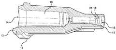
도 1은 분배 팁이 분배 튜브를 포함하는 분배 주사기의 등각도를 도시한다.
도 2는 분배 튜브를 갖는 분배 팁의 등각도를 도시한다.
도 3은 허브의 단면도를 도시한다.
도 4는 접착제를 갖는 분배 튜브의 등각도를 도시한다.
도 5는 도 4의 분배 튜브의 단면도를 도시한다.
도 6은 다른 분배 튜브의 단면도를 도시한다.
도 7a는 분배 튜브의 측면 사시도를 도시한다.
도 7b는 도 7의 분배 튜브의 단면도를 도시한다.
도 7c는 도 7a 및 도 7b의 분배 튜브의 일부분의 단면도를 도시한다.
도 7d는 다른 분배 튜브의 단면도를 도시한다.
본 발명의 태양이 이제 도면을 참조하여 상세히 설명될 것이며, 여기서 동일한 도면 부호는 달리 명시되지 않는 한 전체에 걸쳐 동일한 요소를 지칭한다.The present application is further understood when reading in connection with the accompanying drawings. To illustrate the invention, an exemplary embodiment of the invention is shown in the drawings, but the presently disclosed invention is not limited to the specific methods, apparatus, and systems disclosed. In the drawing,
1 shows an isometric view of a dispensing syringe in which the dispensing tip comprises a dispensing tube.
2 shows an isometric view of a dispensing tip with a dispensing tube.
3 shows a cross-sectional view of a hub.
4 shows an isometric view of a dispensing tube with adhesive.
5 shows a cross-sectional view of the dispensing tube of FIG. 4.
6 shows a cross-sectional view of another dispensing tube.
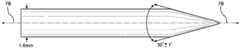
7A shows a side perspective view of a dispensing tube.
FIG. 7B shows a cross-sectional view of the dispensing tube of FIG. 7.
7C shows a cross-sectional view of a portion of the dispensing tube of FIGS. 7A and 7B.
7D shows a cross-sectional view of another dispensing tube.
Aspects of the invention will now be described in detail with reference to the drawings, wherein like reference numerals refer to like elements throughout unless otherwise specified.
액체 물질은 여러 상이한 방식들로 그리고 상이한 디스펜서들, 분배 메커니즘들, 및 분배 패턴들을 사용하여 분배될 수 있다. 도 1은 예시적인 액체 분배 주사기(30)를 도시한다. 주사기(30)는 액체 물질을 분배하기 위한 분배 단부를 갖는 긴 관형 몸체를 포함한다. 일부 태양에서, 피스톤이 주사기(30) 내에 활주가능하게 배치될 수 있고, 그 내에서 분배 단부를 향해 또는 그로부터 멀리 활주가능하게 이동가능할 수 있다. 분배 팁(10)이 주사기(30)에 제거가능하게 결합되어, 주사기(30) 내의 물질이 그로부터 분배 팁(10)으로 이동될 수 있게 하고, 후속하여, 그에 영구적으로 또는 해제가능하게 연결된 분배 튜브(100)로부터 분배되게 한다. 주사기(30)가 도면에 도시되어 있지만, 임의의 적합한 용기가 액체 물질을 수용하고 분배 팁(10)과 결합하는 데 이용될 수 있다는 것은 이해될 것이다.The liquid material may be dispensed in several different ways and using different dispensers, dispensing mechanisms, and dispensing patterns. 1 shows an exemplary liquid dispensing
분배 팁(10)은 나사산, 루어 로크(Luer lock), 스냅 끼워맞춤, 마찰 끼워맞춤, 또는 다른 보유 메커니즘과 같은, 분배 분야에서 전형적으로 이용되는 임의의 공지된 연결 방법을 통해 주사기(30) 또는 다른 적합한 용기와 결합될 수 있다. 도 2 및 도 3을 참조하면, 분배 팁(10)은 근위 단부(13) 및 근위 단부(13)의 반대편에 있는 원위 단부(15)를 갖는 허브(12)를 포함한다. 분배 팁(10)을 주사기(30)에 고정시키는 것을 돕기 위해 나사산(17)이 근위 단부(13)에 또는 그에 인접하게 배치될 수 있다.Dispensing
제1 개구(14)가 근위 단부(13)에 배치되고, 제2 개구(16)가 원위 단부(15)에 배치된다. 허브(12)는 내부가 적어도 부분적으로 중공이고, 근위 단부(13)와 원위 단부(15) 사이에서 연장되고 제1 개구(14) 및 제2 개구(16)와 유체 연통하는 챔버(19)를 한정한다.The
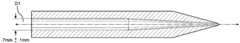
원위 단부(15)에서 분배 팁(10)의 허브(12)에 분배 튜브(100)가 결합된다. 도 4 내지 도 7d를 참조하면, 분배 튜브(100)는 실질적으로 원통형인 부분 및 실질적으로 원추형인 부분을 갖는 것으로 도시되어 있다. 그러나, 다른 형상 및 형상들의 조합, 예컨대, 프리즘형, 구형 또는 반구형, 사다리꼴, 또는 형상들의 다른 조합이 가능하다는 것이 이해될 것이다. 분배 튜브(100)는 근위 단부(102) 및 근위 단부의 반대편에 있는 원위 단부(106)를 갖는다.Dispensing
허브(12)의 챔버(19)를 통해 유동하는 액체 물질을 수용하기 위한 입구(104)가 근위 단부(102)에 배치된다. 액체 물질은 제2 개구(16)를 통해 챔버(19)로부터 그리고 입구(104)를 통해 분배 튜브(100) 내로 지나갈 수 있다. 분배 튜브(100)는 그를 통해 근위 단부(102)로부터 원위 단부(106)로 연장되는 채널(110)을 한정한다. 출구(108)가 원위 단부(106)에 배치되고, 채널(110)과 유체 연통한다. 액체 물질은 분배 튜브(100)를 통해 그리고 입구(104)로부터 출구(108)로 축방향으로 연장되는 분배 축(A)을 따라 출구(108)를 통해 외부로 이동할 수 있다.An
분배 튜브(100)는 채널(110)이 일정한 단면 형상 및/또는 직경을 갖도록, 또는 그가 가변 형상 또는 직경을 가질 수 있도록 제조될 수 있다. 일부 태양에서, 예를 들어 채널(110)은 상이한 치수를 갖는 다수의 섹션을 포함할 수 있다. 도 5를 참조하면, 예를 들어, 채널(110)은 전이점(transition point)(116)에 의해 제2 섹션(114)으로부터 분리된 제1 섹션(112)을 포함할 수 있다. 채널(110)의 제1 섹션(112)이 제1 직경(D1)을 가질 수 있는 한편, 제2 섹션(114)은 제2 직경(D2)을 갖는 분배 튜브(100)의 출구(108)로 테이퍼질 수 있다. 도면에 도시된 바와 같이, 제1 직경(D1)은 제2 직경(D2)보다 클 수 있다.
채널(110)의 제1 섹션(112)은 근위 단부(102)와 전이점(116) 사이에 한정될 수 있고, 실질적으로 원통형일 수 있고, 채널을 통해 일정한 직경을 가질 수 있다. 일부 태양에서, 입구(104)는 제1 섹션(112)과 동일한 단면 형상(예컨대, 원형)을 가질 수 있고, 제1 직경(D1)과 동일한 직경을 갖도록 치수설정될 수 있다.The
제2 섹션(114)은 전이점(116)과 원위 단부(106) 사이에 한정될 수 있고, 그 섹션 내의 채널(110)이 가변 치수를 갖도록 한정될 수 있다. 일부 태양에서, 제2 섹션(114)은 채널(110)이 전이점(116)으로부터 원위 단부(106)를 향하는 방향으로 더 좁아지도록 테이퍼를 포함할 수 있다.The
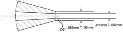
분배 튜브(100)는 제조 선호도, 분배될 액체 물질, 기재 상의 분배된 물질의 치수, 또는 다른 인자에 기초하여 상이한 제1 및 제2 직경(D1, D2)을 갖도록 설계될 수 있다. 제1 직경(D1)은 제2 직경(D2)보다 클 수 있어서, 액체 물질이 분배 튜브(100)를 통해 근위 단부(102)로부터 원위 단부(106)로 이동됨에 따라, 액체 물질이 더 큰 제1 직경(D1)으로부터 더 작은 제2 직경(D2)으로의 방향으로 이동하게 한다. 이와 같이, 더 큰 제1 직경(D1)은 액체 물질을 분배 튜브(100)를 통해 이동시키는 데 더 작은 압력이 요구되게 한다.
제1 직경(D1)은 임의의 적합한 치수, 예컨대 약 0.05 mm 내지 약 5 mm, 약 0.2 mm 내지 약 3 mm, 약 0.5 mm 내지 약 1 mm, 또는 다른 적합한 범위일 수 있다. 일부 태양에서, 제1 직경(D1)은 대략 0.7 mm일 수 있다. 제2 직경(D2)은 또한 임의의 적합한 치수, 예컨대 약 0.001 mm 내지 약 1 mm, 약 0.005 mm 내지 약 0.5 mm, 약 0.01 mm 및 0.1 mm, 약 0.02 mm 내지 약 0.08 mm, 약 0.03 mm 내지 약 0.06 mm, 또는 다른 적합한 범위일 수 있다. 일부 태양에서, 제2 직경(D2)은 대략 0.05 mm일 수 있다. 추가 태양에서, 제2 직경(D2)은 대략 0.035 mm일 수 있다. 제1 및 제2 직경(D1, D2)에 대한 상기 개시된 범위들의 임의의 조합을 이용할 수 있는 상이한 태양들이 존재하고, 제1 직경(D1)이 제2 직경(D2)보다 큰 태양에서, 제1 직경(D1)의 선택된 치수가 제2 직경(D2)의 선택된 치수보다 클 것이라는 것이 이해될 것이다.The first diameter D1 may be in any suitable dimension, such as about 0.05 mm to about 5 mm, about 0.2 mm to about 3 mm, about 0.5 mm to about 1 mm, or other suitable range. In some aspects, the first diameter D1 may be approximately 0.7 mm. The second diameter D2 may also be in any suitable dimension, such as from about 0.001 mm to about 1 mm, from about 0.005 mm to about 0.5 mm, about 0.01 mm and 0.1 mm, about 0.02 mm to about 0.08 mm, about 0.03 mm to about 0.06 mm, or other suitable range. In some aspects, the second diameter D2 may be approximately 0.05 mm. In a further aspect, the second diameter D2 may be approximately 0.035 mm. There are different aspects that may utilize any combination of the above disclosed ranges for the first and second diameters D1, D2, and in embodiments in which the first diameter D1 is greater than the second diameter D2, the first It will be appreciated that the selected dimension of the diameter D1 will be larger than the selected dimension of the second diameter D2.
도면이 2개의 섹션을 갖는 분배 튜브(100)를 도시하지만, 분배 튜브(100)는 3개, 4개, 5개, 또는 임의의 다른 개수의 섹션과 같은 상이한 개수의 섹션을 가질 수 있다는 것은 이해될 것이다. 각각의 섹션은 모든 다른 섹션과 상이한 치수, 또는 대안적으로는, 다른 섹션들 중 하나 이상과 매칭하는 치수를 가질 수 있다. 일부 태양에서, 분배 튜브(100)는 단일 섹션, 예컨대, 제1 섹션(112)과 유사하고 길이를 따라서 일정한 직경을 갖는 섹션, 또는 제2 섹션(114)과 유사하고 길이를 따라서 가변하는 직경을 한정하는 테이퍼를 갖는 섹션을 가질 수 있다.Although the figure shows a dispensing
분배 튜브(100)는 전체에 걸쳐 일정한 직경을 가질 수 있거나 또는 대안적으로 제2 섹션(114)과 동일한 테이퍼 각도(α)로 또는 상이한 테이퍼 각도로 테이퍼질 수 있는 제3 섹션(도시되지 않음)을 추가로 포함할 수 있다. 제3 섹션은 제1 섹션(112), 제2 섹션(114), 또는 이들 섹션 둘 모두에 인접할 수 있다.
일부 태양에서, 제2 섹션(114)에 존재하는 테이퍼는 일정할 수 있다. 도 6을 참조하면, 제2 섹션(114)은 분배 축(A)에 대해 측정되는 테이퍼 각도(α)로 테이퍼질 수 있다. 테이퍼 각도(α)는, 길이, 두께, 원하는 직경(예컨대, 직경(D1) 또는 직경(D2)), 원하는 적용, 분배될 액체, 또는 테이퍼 사양에 의해 영향을 받을 수 있는 다른 인자와 같은, 분배 튜브(100)의 매개변수뿐만 아니라, 제조 선호도 및 능력에 따라 선택될 수 있다는 것이 이해될 것이다.In some aspects, the taper present in the
대안적인 태양에서, 제2 섹션(114)의 테이퍼는 그의 길이를 따라 가변될 수 있다. 예를 들어, 분배 축(A)으로부터 측정된 테이퍼 각도(α)는 제2 섹션(114)의 길이를 따라 증가 또는 감소할 수 있다. 이는 테이퍼 각도(α)가 증가하는지 또는 감소하는지(도시되지 않음)에 따라, 제2 섹션(114)에 인접한 분배 튜브(100)의 내부를 볼록하거나 오목한 것으로 한정할 수 있다. 테이퍼 각도(α)는, 예를 들어, 약 1° 내지 약 60°, 약 3° 내지 약 30°, 또는 약 5° 내지 약 15°일 수 있다.In an alternative aspect, the taper of the
분배 튜브(100)는 상이한 적합한 재료, 예를 들어 금속, 플라스틱, 합금, 및/또는 세라믹으로부터 제조될 수 있다. 일부 태양에서, 분배 튜브(100)는 스테인레스강과 같은 강을 포함할 수 있다. 대안적인 태양에서, 분배 튜브(100)는 세라믹, 예컨대, 블랙 세라믹, 예컨대, 블랙 지르코니아를 포함할 수 있다. 또 다른 태양에서, 분배 튜브(100)는 지르코니아 강화 알루미나를 포함할 수 있다. 분배 튜브(100)는 전체에 걸쳐 균일한 구성을 갖도록, 또는 대안적으로, 분배 튜브(100)의 다양한 부분들에서 상이한 분포의 재료를 갖도록 제조될 수 있다. 분배 튜브(100)를 구성하는 재료가 액체 물질의 용이한 활주를 허용하여야 하고 액체 물질의 유동에 악영향을 주지 않아야 한다는 것은 이해될 것이다.
분배 튜브(100)는, 혼합물로서, 또는 분배 튜브(100)의 상이한 부분들이 상이한 재료들을 포함하는, 재료들의 조합을 포함할 수 있다. 예를 들어, 원위 단부(106)는 근위 단부(102)와 상이한 재료, 예컨대, 분배 동작과 연관된 응력을 견디기 위해 더 경질인 재료를 포함할 수 있다. 일부 태양에서, 코팅이, 채널(110) 내측의 액체 물질이 코팅(도시되지 않음)과 접촉하도록 분배 튜브(100)의 내부에 적용될 수 있다. 코팅이 또한 분배 튜브(100)의 다른 부분에, 예를 들어 외부 표면에 적용될 수 있다는 것은 이해될 것이다. 일부 태양에서, 코팅은 폴리테트라플루오로에틸렌(PTFE) 또는 다른 적합한 재료를 포함할 수 있다.
분배 튜브(100)는 본 출원 전체에 걸쳐 개시된 바와 같은 임의의 적합한 보유 방법을 통해 분배 팁(10)의 허브(12)에 또는 그 내에 고정될 수 있다. 일부 태양에서, 접착제(20)가 분배 튜브(100)를 허브(12)에 연결하는 데 사용될 수 있다. 접착제(20)는 임의의 적합한 접착제를 포함할 수 있다. 접착제(20)의 조성은 분배 튜브(100) 및 허브(12) 내에 존재하는 물질에 따라 좌우될 것이어서, 접착제가 구성요소들을 서로 효과적으로 고정시킬 수 있게 할 것으로 이해될 것이다. 일부 태양에서, 접착제(20)는 분배 튜브(100)와 허브(12) 사이의 공간에 용이하게 진입하기에 충분히 낮은 점도를 갖는 유동성 접착제를 포함할 수 있다. 이어서, 접착제(20)는 덜 점성이 되도록 고형화되게 할 수 있다. 접착제(20)는 외부 개입 없이 주어진 건조 기간의 경과 시 자체적으로 고형화될 수 있거나, 또는 대안적으로, 접착제(20)는 경화 공정(예를 들어, 자외광, 고온, 경화 유체, 또는 경화 공정을 가속시키는 다른 인자에 대한 노출)을 활성화시키도록 처리될 수 있다.
도 3 및 도 4를 참조하면, 분배 튜브(100)는 분배 팁(10) 상의 허브(12)의 원위 단부(15)에 또는 그에 인접하게 배치된 리셉터클(18) 내로 부분적으로 삽입될 수 있다. 리셉터클(18)은 챔버(19)와 유체 연통하고, 챔버(19)로부터 액체 물질을 수용하여 그것이 분배 튜브(100)로 통과하게 할 수 있다. 리셉터클(18)은, 분배 팁(10)의 나머지와 분배 튜브(100)의 결합을 개선하기 위해, 분배 튜브(100), 접착제(20), 또는 이들 둘 모두와 결합하도록 구성된 하나 이상의 보유 부재(21)를 포함할 수 있다. 보유 부재(21)는 분배 튜브(100)와 허브(12) 사이의 접촉을 증가시키도록 구성된 리브, 노치, 돌출부, 나사산, 또는 다른 구조적 특징부를 포함할 수 있다. 일부 태양에서, 분배 튜브(100)는 분배 팁(10) 상의 보유 부재(21)에 더하여 또는 그 대신에 보유 부재(도시되지 않음)를 가질 수 있다.Referring to FIGS. 3 and 4, the dispensing
분배 튜브(100)를 갖는 분배 팁(10)은 그들이 함께 사용되는 분배 장치, 예를 들어 주사기(30)로부터 연결해제될 수 있고, 분배 튜브(100)를 갖는 상이한 분배 팁(10)이 대신 연결될 수 있다. 분배 공정 동안, 작동 중의 지속적인 손상으로 인해 분배 팁(10), 분배 튜브(100), 또는 이들의 조합을 교체하는 것이 유리할 수 있다. 본 출원 전체에 걸쳐 설명되는 구성요소들은 분배 동안 다양한 응력을 받게 되어, 이들은 설정된 기간의 분배 시간 후에 또는 주어진 양의 물질이 분배된 후에 파손되거나, 만곡되거나, 균열되거나, 달리 손상을 입을 수 있다. 허브(12) 또는 분배 튜브(100)와 같은 분배 팁(10)의 구성요소는 작동 과정에 걸쳐 하나 이상의 물질에 의해 막힐 수 있다. 더욱이, 분배 공정이 유지보수 또는 다른 이유로 인해 비작동 상태일 때 구성요소를 교체하는 것이 바람직할 수 있다. 추가로, 본 명세서에서 논의되는 분배 팁(10) 및 분배 튜브(100)의 상이한 태양이 분배될 특정 액체 물질 또는 특정 분배 패턴에 따라 이용될 수 있으며, 상이한 액체 물질이 도입되려고 하거나 상이한 분배 패턴이 선택될 때, 분배 팁(10) 및/또는 분배 튜브(100)는 교체될 수 있다.The dispensing
원하는 분배 패턴, 양, 지속 시간, 속도 및 다른 인자에 기초하여 다양한 분배 매개변수가 사전설정되거나 사전프로그래밍된다. 분배 매개변수는 분배 팁(10)의 구조적 특징부, 구체적으로는 허브(12) 및/또는 분배 튜브(100)와 관련된 것과 관련된다. 허브(12) 및 분배 튜브(100) 내의 압력, 액체 물질의 유량, 및 점도뿐만 아니라 다른 요인이 고유의 분배 매개변수에 대응할 수 있다. 기존의 분배 시스템에서, 분배 튜브는 종종 가변하는 직경을 가졌고, 분배 튜브는 만곡되거나 구부러지기 쉬웠고, 물질은 종종 분배 튜브 내에 점착되어, 유동에 대한 장애물을 생성하였다. 기존의 분배 튜브는 큰 제조 공차를 가지며, 이는 튜브를 통해 연장되는 일관성 없는 크기의 출구 오리피스 및 채널을 야기한다. 이는 물질의 신뢰할 수 없고 일관성 없는 분배 및 상이한 세트의 분배 매개변수들을 야기할 수 있다. 기존 튜브의 제조 공정 및 사용되는 물질에 기초하면, 공차는 낮아질 수 없다. 손상된 분배 튜브가 교체될 때, 새로운 튜브는 상이한 만곡, 구부러짐, 및 상이하게 치수설정된 내경으로 인해 상이한 특성을 가질 가능성이 있다. 이는 물질이 분배되는 방식에 영향을 미치고, 분배 매개변수는 일관된 분배를 보장하기 위해 조절 또는 재교정되어야 한다.Various distribution parameters are preset or preprogrammed based on the desired distribution pattern, amount, duration, speed and other factors. Dispensing parameters relate to the structural features of dispensing
다른 한편으로, 본 명세서의 분배 튜브(100)의 개시된 태양은 더 작은 내경 공차를 가지며, 분배 튜브(100)의 예시적인 형상 및 치수는 증가된 내구성을 제공하고 튜브의 수명에 걸쳐 물질의 더 일관된 분배를 가능하게 한다. 더욱이, 더 작은 공차로 인해, 개별 분배 튜브(100)들 사이에서 치수는 더 큰 일관성을 갖는다. 이러한 개선된 일관성은 분배 시스템의 분배 매개변수의 작은 변경을 허용하고, 튜브 또는 팁이 교체될 때 분배 매개변수를 재교정할 필요성을 감소시킨다.On the other hand, the disclosed aspects of the dispensing
본 출원 전체에 걸쳐 개시된 분배 튜브(100)는 기존의 분배 튜브 내의 대응하는 출구 오리피스보다 작은 출구(108)를 가질 수 있다. 액체 물질은, 긴 스트랜드 및/또는 소적(droplet)과 같은 다양한 형상 및 패턴으로 분배 튜브(100)로부터 기재(도시되지 않음) 상에 분배될 수 있다. 소적이 기재 상에 형성되는 태양에서, 개시된 분배 튜브(100)는 분배된 소적이 기존의 분배 튜브로부터 분배되는 것보다 더 작게 되는 것을, 예를 들어, 기존 소적 크기의 약 2/3, 기존 소적 크기의 약 1/2, 기존 소적 크기의 1/3, 또는 기존 소적 크기의 약 1/4이 되는 것을 가능하게 할 수 있다. 침착된 액체 물질의 더 작은 크기는, 액체 물질이 분배되는 양 및 그가 분배되는 기재 상의 위치의 더 우수한 제어를 가능하게 하기 때문에 유리할 수 있다. 이는 또한, 분배된 소적의 밀도, 소적의 형상, 및 분배의 지속 시간과 같은, 분배 패턴의 더 우수한 제어를 위한 옵션을 제공한다.
도 7a에 도시된 바와 같이 약 30도와 같은 테이퍼를 갖는 분배 튜브(예컨대, 제1 섹션(112) 및 제2 섹션(114)을 가짐)에서, 물질의 유동은 각각의 입구에서 출구까지 일정한 내경을 갖는 기존의 분배 튜브들에 비해 개선된다. 현재 사용되는 분배 튜브는 종종 그를 통한 액체 물질의 유동에 대해 바람직하지 않게 높은 저항을 갖는다. 따라서, 기존의 분배 튜브는 액체 물질을 분배 튜브 내로, 그를 통해, 그리고 그의 외부로 이동시키기 위해 고압의 인가를 필요로 한다. 이는 분배 튜브의 더 빠른 열화, 압력을 인가하는 데 사용되는 낭비되는 에너지, 및 액체 물질의 일관되지 않은 분배 및 기재 상의 침착물의 형성을 야기할 수 있다. 이는 또한 원하는 침착물 크기를 달성하기 위해 더 많은 시간을 필요로 한다. 본 출원 전체에 걸쳐 개시된 분배 튜브(100)의 태양에서, 액체 물질이 제1 직경(D1)을 갖는 제1 섹션(112)으로부터 제1 직경(D1)보다 작은 제2 직경(D2)을 갖는 제2 섹션(114) 내로 이동할 때, 제2 섹션(114)을 통해 이동하는 액체 물질의 속도는 그의 제1 섹션(112)에서의 속도에 비해 증가한다. 이와 같이, 분배 튜브(100)를 통해 원하는 양의 액체 물질을 이동시키기 위해서, 기존의 분배 튜브의 경우보다 적은 압력이 필요할 수 있다. 예를 들어, 압력은 약 5 psig 내지 약 100 psig의 범위일 수 있고, 속도는 약 0.001 m/sec 내지 약 1.0 m/sec의 범위일 수 있다.In a dispensing tube (eg, having a
시스템 및 방법이 다양한 도면의 다양한 실시예와 관련하여 설명되었지만, 넓은 본 발명의 개념으로부터 벗어나지 않고서 실시예에 대한 변경이 이루어질 수 있다는 것을 당업자는 이해할 것이다. 따라서, 본 발명은 개시된 특정 실시예로 제한되지 않으며, 이는 청구범위에 의해 한정되는 바와 같은 본 발명의 사상 및 범주 내의 변형을 포괄하는 것으로 의도된다.Although the systems and methods have been described in connection with various embodiments of the various figures, it will be understood by those skilled in the art that changes may be made to the embodiments without departing from the broad inventive concept. Accordingly, the invention is not limited to the particular embodiments disclosed, which are intended to cover modifications within the spirit and scope of the invention as defined by the claims.
Claims (21)
Translated fromKorean상기 분배 주사기에 연결되도록 구성된 허브에 연결되도록 구성된 근위 단부, 및 상기 근위 단부의 반대편에 있는 원위 단부를 갖는 몸체;
상기 근위 단부와 상기 원위 단부 사이에서 상기 몸체를 통해 연장되는 채널;
상기 근위 단부에 있고, 상기 채널과 유체 연통하고, 상기 채널 내로 상기 액체 물질을 수용하도록 구성된 입구; 및
상기 원위 단부에 있고, 상기 채널과 유체 연통하는 출구를 포함하고,
상기 채널은, 상기 근위 단부가 제1 내경을 갖고 상기 출구가 상기 제1 내경보다 작은 제2 내경을 갖도록 원위 방향으로 부분적으로 테이퍼진, 튜브.A tube for use with a dispensing syringe for dispensing a liquid substance,
A body having a proximal end configured to connect to a hub configured to connect to the dispensing syringe, and a distal end opposite the proximal end;
A channel extending through the body between the proximal end and the distal end;
An inlet at the proximal end and in fluid communication with the channel and configured to receive the liquid material into the channel; And
An outlet at said distal end and in fluid communication with said channel,
The channel is partially tapered in the distal direction such that the proximal end has a first inner diameter and the outlet has a second inner diameter less than the first inner diameter.
상기 액체 물질을 수용하도록 구성된 내부 격실을 갖는 배럴(barrel); 및
상기 배럴에 제거가능하게 연결되도록 구성되고, 상기 배럴의 내부 격실과 유체 연통하고 상기 내부 격실로부터 상기 액체 물질을 수용하도록 구성된 챔버를 갖는 분배 팁을 포함하고,
상기 분배 팁은 분배 튜브를 포함하고, 상기 분배 튜브는 근위 단부에 있는 입구와 원위 단부에 있는 출구 사이에서 상기 분배 튜브를 통해 연장되는 채널을 갖고, 상기 분배 튜브는 상기 액체 물질을 상기 입구에서 상기 채널 내로 수용하고 상기 액체 물질을 상기 출구의 외부로 분배하도록 구성되고,
상기 채널은 원위 방향으로 부분적으로 테이퍼진, 분배 장치.A dispensing device for dispensing a liquid substance,
A barrel having an interior compartment configured to receive the liquid material; And
A dispensing tip configured to be removably connected to the barrel, the dispensing tip having a chamber in fluid communication with the inner compartment of the barrel and configured to receive the liquid material from the inner compartment;
The dispensing tip includes a dispensing tube, the dispensing tube having a channel extending through the dispensing tube between an inlet at the proximal end and an outlet at the distal end, wherein the dispensing tube causes the liquid material to disengage at the inlet. Receive into the channel and distribute the liquid material out of the outlet,
The channel is partially tapered in the distal direction.
상기 액체 물질을 분배 장치 내로 제공하는 단계 - 상기 분배 장치는 상기 액체 물질을 분배하기 위한 튜브를 갖고, 상기 튜브는 그를 통해 연장되는 채널을 가짐 -;
제1 내경을 갖는 상기 채널의 제1 부분을 통해 상기 액체 물질을 이동시키는 단계;
상기 채널의 테이퍼진 제2 부분을 통해 상기 제1 내경보다 작은 제2 내경을 갖는 출구로 상기 액체 물질을 이동시키는 단계; 및
기재 상에 상기 액체 물질의 침착물을 형성하는 단계를 포함하는, 방법.As a method of dispensing a liquid substance,
Providing the liquid material into a dispensing device, the dispensing device having a tube for dispensing the liquid material, the tube having a channel extending therethrough;
Moving the liquid material through the first portion of the channel having a first inner diameter;
Moving the liquid material through the tapered second portion of the channel to an outlet having a second inner diameter less than the first inner diameter; And
Forming a deposit of the liquid material on a substrate.
상기 분배 장치로부터 상기 튜브를 제거하는 단계; 및
제2 튜브를 상기 분배 장치에 연결하는 단계를 추가로 포함하는, 방법.The method of claim 20,
Removing the tube from the dispensing device; And
Connecting a second tube to the dispensing device.
Applications Claiming Priority (4)
| Application Number | Priority Date | Filing Date | Title |
|---|---|---|---|
| US201862703576P | 2018-07-26 | 2018-07-26 | |
| US62/703,576 | 2018-07-26 | ||
| US201916520871A | 2019-07-24 | 2019-07-24 | |
| US16/520,871 | 2019-07-24 |
Publications (1)
| Publication Number | Publication Date |
|---|---|
| KR20200012776Atrue KR20200012776A (en) | 2020-02-05 |
Family
ID=67438954
Family Applications (1)
| Application Number | Title | Priority Date | Filing Date |
|---|---|---|---|
| KR1020190090096ACeasedKR20200012776A (en) | 2018-07-26 | 2019-07-25 | Dispensing tube for dispensing liquid materials |
Country Status (4)
| Country | Link |
|---|---|
| EP (1) | EP3599032A1 (en) |
| JP (1) | JP2020015038A (en) |
| KR (1) | KR20200012776A (en) |
| CN (1) | CN110773379B (en) |
Families Citing this family (2)
| Publication number | Priority date | Publication date | Assignee | Title |
|---|---|---|---|---|
| KR20220039752A (en)* | 2019-08-02 | 2022-03-29 | 노드슨 코포레이션 | Dispensing tip and method of making the same |
| CN114849969A (en)* | 2022-02-25 | 2022-08-05 | 合肥晶弘电器有限公司 | A kind of glue discharging head and its forming machine |
Family Cites Families (13)
| Publication number | Priority date | Publication date | Assignee | Title |
|---|---|---|---|---|
| US5030208A (en)* | 1989-03-22 | 1991-07-09 | Novacek Laurel A | Safety syringe needle device with interchangeable and retractable needle platform |
| US5249716A (en)* | 1993-04-12 | 1993-10-05 | Sullivan Paul O | Caulking nozzle assembly |
| US5816804A (en)* | 1996-01-19 | 1998-10-06 | Ultradent Products, Inc. | Fiber-ended open orifice delivery tip |
| US6065645A (en)* | 1997-04-01 | 2000-05-23 | Discus Dental Impressions, Inc. | Double-barreled syringe with detachable locking mixing tip |
| US6547167B1 (en)* | 1999-01-26 | 2003-04-15 | Jeffrey Fugere | Fluid dispense tips |
| US6981664B1 (en)* | 2000-01-26 | 2006-01-03 | Dl Technology Llc | Fluid dispense tips |
| US6616019B2 (en)* | 2001-07-18 | 2003-09-09 | Closure Medical Corporation | Adhesive applicator with improved applicator tip |
| US20070187437A1 (en)* | 2006-02-10 | 2007-08-16 | Nordson Corporation | Dispensing tip for liquid dispensing systems and method of making the same |
| JP2008029920A (en)* | 2006-07-26 | 2008-02-14 | Agc Techno Glass Co Ltd | Liquid discharge nozzle and method of manufacturing liquid discharge nozzle |
| KR20080037852A (en)* | 2006-10-27 | 2008-05-02 | 주식회사 탑 엔지니어링 | Nozzle Assembly for Liquid Crystal Dropping Device |
| WO2010028020A1 (en)* | 2008-09-02 | 2010-03-11 | Nscrypt, Inc. | Dispensing patterns including lines and dots at high speeds |
| US8136705B2 (en)* | 2009-04-09 | 2012-03-20 | Illinois Tool Works Inc. | Magnetic drive for dispensing apparatus |
| JP5795571B2 (en)* | 2009-04-15 | 2015-10-14 | ベクトン・ディキンソン・アンド・カンパニーBecton, Dickinson And Company | Fixing member and device enabling mixing in a pen-type syringe |
- 2019
- 2019-07-25KRKR1020190090096Apatent/KR20200012776A/ennot_activeCeased
- 2019-07-25EPEP19188464.2Apatent/EP3599032A1/ennot_activeWithdrawn
- 2019-07-26CNCN201910681347.XApatent/CN110773379B/ennot_activeExpired - Fee Related
- 2019-07-26JPJP2019137942Apatent/JP2020015038A/enactivePending
Also Published As
| Publication number | Publication date |
|---|---|
| CN110773379B (en) | 2023-09-08 |
| EP3599032A1 (en) | 2020-01-29 |
| CN110773379A (en) | 2020-02-11 |
| JP2020015038A (en) | 2020-01-30 |
Similar Documents
| Publication | Publication Date | Title |
|---|---|---|
| US7258253B2 (en) | Method and system for precise dispensation of a liquid | |
| KR101710439B1 (en) | Device for dispensing a filling mass | |
| US7028867B2 (en) | Conformal coating applicator and method | |
| US8359998B2 (en) | Stent coating apparatus and method | |
| US20080294099A1 (en) | Sprayer | |
| KR20200012776A (en) | Dispensing tube for dispensing liquid materials | |
| CN101484242A (en) | Device for mounting pipette tips, pipette tip, and pipetting device | |
| BR112012031013B1 (en) | static spray mixer | |
| AU661229B2 (en) | Sealless dispensing apparatus | |
| JP2014180665A (en) | Liquid dispensing syringe | |
| CN108970818A (en) | Distribute nozzle | |
| CN116018212A (en) | valve tappet | |
| JP5856332B1 (en) | Micro fluid discharge method and micro fluid dispenser | |
| CN111936239A (en) | Liquid material discharge device | |
| US5333755A (en) | Method of manufacture of a static mixing dispenser | |
| US20140263468A1 (en) | Liquid Dispensing Syringe | |
| DE102008037299A1 (en) | Dispenser for dispensing liquid material in form of drop, has actuator, which works on working volume, where working volume is connected with dispensation capillary | |
| US7867548B2 (en) | Thermal ejection of solution having solute onto device medium | |
| DE102014003622B4 (en) | Disposable dispenser | |
| JP6787408B2 (en) | Nozzle for drip tube and drip tube | |
| US20100304496A1 (en) | Fluid dispenser with low surface energy orifice layer for precise fluid dispensing | |
| US8859039B2 (en) | Method of forming lubricative plated layer on viscous liquid feed nozzle and viscous liquid feed nozzle | |
| KR101921509B1 (en) | A nozzle for resin adhesive dispenser | |
| US9889651B2 (en) | Fluid ejection device for depositing a discrete quantity of fluid onto a surface | |
| US20060171853A1 (en) | Tips for pipetting devices or dispensing devices |
Legal Events
| Date | Code | Title | Description |
|---|---|---|---|
| PA0109 | Patent application | Patent event code:PA01091R01D Comment text:Patent Application Patent event date:20190725 | |
| PG1501 | Laying open of application | ||
| PA0201 | Request for examination | Patent event code:PA02012R01D Patent event date:20220720 Comment text:Request for Examination of Application Patent event code:PA02011R01I Patent event date:20190725 Comment text:Patent Application | |
| E902 | Notification of reason for refusal | ||
| PE0902 | Notice of grounds for rejection | Comment text:Notification of reason for refusal Patent event date:20230915 Patent event code:PE09021S01D | |
| PE0902 | Notice of grounds for rejection | Comment text:Notification of reason for refusal Patent event date:20240626 Patent event code:PE09021S01D | |
| E601 | Decision to refuse application | ||
| PE0601 | Decision on rejection of patent | Patent event date:20240901 Comment text:Decision to Refuse Application Patent event code:PE06012S01D |