KR20200001393U - Head of wet cleaner - Google Patents
Head of wet cleanerDownload PDFInfo
- Publication number
- KR20200001393U KR20200001393UKR2020180005886UKR20180005886UKR20200001393UKR 20200001393 UKR20200001393 UKR 20200001393UKR 2020180005886 UKR2020180005886 UKR 2020180005886UKR 20180005886 UKR20180005886 UKR 20180005886UKR 20200001393 UKR20200001393 UKR 20200001393U
- Authority
- KR
- South Korea
- Prior art keywords
- head
- cleaner
- mop
- extension
- head body
- Prior art date
- Legal status (The legal status is an assumption and is not a legal conclusion. Google has not performed a legal analysis and makes no representation as to the accuracy of the status listed.)
- Abandoned
Links
Images


Classifications
- A—HUMAN NECESSITIES
- A47—FURNITURE; DOMESTIC ARTICLES OR APPLIANCES; COFFEE MILLS; SPICE MILLS; SUCTION CLEANERS IN GENERAL
- A47L—DOMESTIC WASHING OR CLEANING; SUCTION CLEANERS IN GENERAL
- A47L11/00—Machines for cleaning floors, carpets, furniture, walls, or wall coverings
- A47L11/40—Parts or details of machines not provided for in groups A47L11/02 - A47L11/38, or not restricted to one of these groups, e.g. handles, arrangements of switches, skirts, buffers, levers
- A47L11/4036—Parts or details of the surface treating tools
- A47L11/4038—Disk shaped surface treating tools
- A—HUMAN NECESSITIES
- A47—FURNITURE; DOMESTIC ARTICLES OR APPLIANCES; COFFEE MILLS; SPICE MILLS; SUCTION CLEANERS IN GENERAL
- A47L—DOMESTIC WASHING OR CLEANING; SUCTION CLEANERS IN GENERAL
- A47L11/00—Machines for cleaning floors, carpets, furniture, walls, or wall coverings
- A47L11/28—Floor-scrubbing machines, motor-driven
- A47L11/282—Floor-scrubbing machines, motor-driven having rotary tools
- A47L11/283—Floor-scrubbing machines, motor-driven having rotary tools the tools being disc brushes
- A—HUMAN NECESSITIES
- A47—FURNITURE; DOMESTIC ARTICLES OR APPLIANCES; COFFEE MILLS; SPICE MILLS; SUCTION CLEANERS IN GENERAL
- A47L—DOMESTIC WASHING OR CLEANING; SUCTION CLEANERS IN GENERAL
- A47L11/00—Machines for cleaning floors, carpets, furniture, walls, or wall coverings
- A47L11/40—Parts or details of machines not provided for in groups A47L11/02 - A47L11/38, or not restricted to one of these groups, e.g. handles, arrangements of switches, skirts, buffers, levers
- A47L11/4036—Parts or details of the surface treating tools
- A47L11/4044—Vacuuming or pick-up tools; Squeegees
- A—HUMAN NECESSITIES
- A47—FURNITURE; DOMESTIC ARTICLES OR APPLIANCES; COFFEE MILLS; SPICE MILLS; SUCTION CLEANERS IN GENERAL
- A47L—DOMESTIC WASHING OR CLEANING; SUCTION CLEANERS IN GENERAL
- A47L11/00—Machines for cleaning floors, carpets, furniture, walls, or wall coverings
- A47L11/40—Parts or details of machines not provided for in groups A47L11/02 - A47L11/38, or not restricted to one of these groups, e.g. handles, arrangements of switches, skirts, buffers, levers
- A47L11/4063—Driving means; Transmission means therefor
- A47L11/4069—Driving or transmission means for the cleaning tools
- A—HUMAN NECESSITIES
- A47—FURNITURE; DOMESTIC ARTICLES OR APPLIANCES; COFFEE MILLS; SPICE MILLS; SUCTION CLEANERS IN GENERAL
- A47L—DOMESTIC WASHING OR CLEANING; SUCTION CLEANERS IN GENERAL
- A47L11/00—Machines for cleaning floors, carpets, furniture, walls, or wall coverings
- A47L11/40—Parts or details of machines not provided for in groups A47L11/02 - A47L11/38, or not restricted to one of these groups, e.g. handles, arrangements of switches, skirts, buffers, levers
- A47L11/4075—Handles; levers
- A—HUMAN NECESSITIES
- A47—FURNITURE; DOMESTIC ARTICLES OR APPLIANCES; COFFEE MILLS; SPICE MILLS; SUCTION CLEANERS IN GENERAL
- A47L—DOMESTIC WASHING OR CLEANING; SUCTION CLEANERS IN GENERAL
- A47L11/00—Machines for cleaning floors, carpets, furniture, walls, or wall coverings
- A47L11/40—Parts or details of machines not provided for in groups A47L11/02 - A47L11/38, or not restricted to one of these groups, e.g. handles, arrangements of switches, skirts, buffers, levers
- A47L11/4094—Accessories to be used in combination with conventional vacuum-cleaning devices
Landscapes
- Nozzles For Electric Vacuum Cleaners (AREA)
Abstract
Translated fromKoreanDescription
Translated fromKorean본 고안은 물걸레 청소기 헤드에 관한 것으로, 더욱 상세하게는 진공청소기의 헤드에 물걸레 기능이 추가된 물걸레 청소기 헤드에 관한 것이다.The present invention relates to a mop cleaner head, and more particularly, to a mop cleaner head having a mop function added to the head of a vacuum cleaner.
진공청소기는 집안 등의 실내에서 바닥 등을 청소하기 위해 사용한다. 이러한 진공청소기는 진공을 이용하여 바닥에 쌓인 먼지나 작은 이물질 등을 제거할 수 있다. 그런데, 이러한 진공청소기는 바닥과 쉽게 분리되는 먼지나 이물질을 제거하기에는 용이하지만, 바닥에 달라붙은 먼지나 기름때, 혹은 음식물 찌꺼기 등을 제거하기에는 어려운 문제가 있다.Vacuum cleaners are used to clean floors, etc., in the interior of the house. The vacuum cleaner may remove dust or small foreign matter accumulated on the floor by using a vacuum. However, such a vacuum cleaner is easy to remove dirt or foreign matter that is easily separated from the floor, but there is a problem in that it is difficult to remove dirt, grease, or food residues and the like that have adhered to the floor.
그에 따라 최근 이렇게 바닥에 달라붙은 먼지, 기름때 또는 음식물 찌꺼기 등을 쉽게 청소하기 위해 스팀청소기가 개발되어 사용되고 있으며, 또한, 진동이나 회전되어 걸레질을 편리하게 할 수 있는 물걸레 청소기도 출시되고 있다.Accordingly, recently, a steam cleaner has been developed and used to easily clean dust, grease, or food residues stuck to the floor. In addition, a water mop cleaner that can be easily cleaned by vibration or rotation has been released.
그런데, 상기와 같은, 스팀청소기나 물걸레 청소기는 지저분한 바닥을 청소할 때, 단독으로 사용하는 것은 효과적이지 않고, 진공청소기를 이용하여 1차적으로 청소를 한 다음, 스팀청소기나 물걸레 청소기를 이용하여 재차 청소를 하여야 하는 번거로움이 있다.However, as described above, when cleaning a dirty floor with a steam cleaner or a mop cleaner, it is not effective to use it alone, and is first cleaned using a vacuum cleaner, and then cleaned again using a steam cleaner or a mop cleaner There is a hassle to do.
그렇지 않고, 진공청소기로 청소를 하지 않은 상태에서, 스팀청소기나 물걸레 청소기를 이용하여 청소를 하는 경우, 바닥의 이물질이 걸레에 그대로 묻어 이동되거나 바닥에 남아 다시 청소를 하여야 한다. 특히 물걸레에 의해 먼지나 이물질이 젖는 경우, 오히려 바닥이 지저분해지는 문제가 발생할 수 있다.Otherwise, when cleaning with a vacuum cleaner or a mop cleaner without cleaning with a vacuum cleaner, the foreign matter on the floor must be transferred to the mop or left on the floor to be cleaned again. In particular, when dust or a foreign substance gets wet by a mop, a problem may arise that the floor becomes dirty.
본 고안이 해결하고자 하는 과제는, 물걸레를 이용하여 바닥을 닦을 때, 바닥의 먼지나 이물질을 제거할 수 있는 물걸레 청소기 헤드를 제공하는 것이다.The problem to be solved by the present invention is to provide a mop cleaner head capable of removing dust or foreign substances on the floor when wiping the floor using a mop.
본 고안의 일 실시예에 따른 물걸레 청소기 헤드는, 일 측에 청소기 본체와 연결되기 위한 결합부가 구비되고, 상기 결합부에 형성된 전원연결부를 통해 상기 청소기 본체로부터 전원이 공급되어 공급된 전원에 의해 구동되는 하나 이상의 회전모터가 내부에 구비된 헤드 본체부; 상기 헤드 본체부의 하부에 배치되고, 상기 하나 이상의 회전모터의 구동에 의해 회전되며, 각각 걸레가 결합되는 한 쌍의 회전부; 및 상기 헤드 본체부와 청소기 본체를 연결하도록 소정의 길이를 갖는 연장부를 포함하고, 상기 헤드 본체부의 하면에는 상기 청소기 본체의 구동에 의해 상기 헤드 본체부 하부의 먼지나 이물질이 흡입되기 위한 흡입구가 형성되며, 상기 연장부는 상기 흡입구를 통해 흡입된 먼지나 이물질이 상기 청소기 본체로 이송시키기 위해 내부에 중공이 형성되고, 중간 부분이 소정의 각도로 꺾이도록 형성될 수 있다.The mop cleaner head according to an embodiment of the present invention is provided with a coupling portion for connecting to the cleaner body on one side, and is powered by power supplied from the cleaner body through a power connection formed in the coupling portion A head body part having one or more rotating motors provided therein; A pair of rotating parts which are disposed under the head body part, are rotated by the driving of the one or more rotating motors, and each mop is coupled; And an extension part having a predetermined length to connect the head body part and the cleaner body, and a suction port for suctioning dust or foreign substances under the head body part is formed on the lower surface of the head body part by driving the cleaner body. And, the extension may be formed such that a hollow is formed inside and the middle portion is bent at a predetermined angle so that dust or foreign substances sucked through the suction port are transferred to the cleaner body.
상기 연장부는, 상기 청소기 본체에 결합되며, 중공이 형성되고, 소정의 길이를 갖는 제1 연장부재; 상기 결합부에 결합되고, 중공이 형성되며, 소정의 길이를 갖는 제2 연장부재; 및 상기 제2 연장부재가 상기 제1 연장부재에서 소정의 각도로 꺾이도록 상기 제1 및 제2 연강부재를 연결하는 꺾임부재를 포함할 수 있다.The extension portion is coupled to the cleaner body, a hollow is formed, a first extension member having a predetermined length; A second extension member coupled to the coupling portion, the hollow being formed, and having a predetermined length; And a bending member connecting the first and second mild steel members so that the second extending member is bent at a predetermined angle from the first extending member.
상기 꺾임부재에 의해 상기 제1 및 제2 연장부재는 90도 이상 180 이하의 각도로 꺾일 수 있다.The first and second extension members may be bent at an angle of 90 degrees or more and 180 degrees or less by the bending member.
상기 제1 및 제2 연장부재는 상기 꺾임부재가 상기 청소기 본체의 하부에 위치하도록 꺾일 수 있다.The first and second extension members may be bent so that the bend member is located under the cleaner body.
상기 한 쌍의 회전부 각각은 상기 헤드 본체부의 전방 외측에서 내측 방향으로 회전되며, 서로 반대 방향으로 회전될 수 있다.Each of the pair of rotating parts is rotated from the front outer side to the inner side of the head body part, and may be rotated in opposite directions.
상기 헤드 본체부의 하면에 배치되되, 상기 흡입구의 전방에 배치되고, 상기 헤드 본체부에서 회전할 수 있도록 배치된 브러시를 더 포함하고, 상기 브러시는 소정의 길이를 가지며, 길이 방향으로 배치된 회전축을 따라 회전할 수 있도록 상기 헤드 본체부에 배치될 수 있다.It is disposed on the lower surface of the head body portion, is disposed in front of the suction port, and further includes a brush disposed to be rotatable in the head body portion, the brush has a predetermined length, the rotation axis disposed in the longitudinal direction It may be disposed on the head body portion so as to rotate accordingly.
상기 헤드 본체부의 하면에는 상기 흡입구에 인접하게 소정의 길이로 홈의 형상으로 흡입가이드가 형성될 수 있다.A suction guide may be formed on the lower surface of the head main body in the shape of a groove with a predetermined length adjacent to the suction port.
상기 흡입가이드가 형성된 길이는 상기 브러시의 길이보다 길게 형성될 수 있다.The length in which the suction guide is formed may be longer than the length of the brush.
상기 걸레는 일면 및 타면 중 선택적으로 상기 한 쌍의 회전부에 결합될 수 있다.The mop may be selectively coupled to the pair of rotating parts among one surface and the other surface.
본 고안에 의하면, 물걸레로 바닥을 청소하면서, 바닥에 있는 먼지나 이물질이 흡입구를 통해 진공청소기 본체로 흡입되므로, 물걸레질과 진공청소기를 이용한 청소를 동시에 할 수 있는 효과가 있다.According to the present invention, while cleaning the floor with a water mop, dust or foreign matter on the floor is sucked into the vacuum cleaner body through the suction port, so there is an effect of simultaneously cleaning with a mop and a vacuum cleaner.
더욱이, 물걸레 청소기 헤드와 청소기 본체를 연결하는 연장부가 소정의 각도로 꺾일 수 있어, 사용자가 엎드리는 동작을 취하지 않더라도 물걸레 청소기 헤드를 소파나 침대 밑으로 넣을 수 있으므로 보다 편리하게 청소할 수 있는 효과가 있다.Moreover, since the extension part connecting the mop cleaner head and the cleaner body can be bent at a predetermined angle, the mop cleaner head can be put under the sofa or bed even if the user does not perform a prone motion, so there is an effect of more convenient cleaning.
또한, 물걸레 청소기 헤드의 전방 측에 회전하는 브러시가 배치되어, 물걸레 청소기 헤드가 이동하면서 회전하여 주변의 먼지 등이 브러시를 통해 보다 원활하게 흡입될 수 있는 효과가 있다.In addition, a rotating brush is disposed on the front side of the mop cleaner head, and the mop cleaner head rotates while moving, so that surrounding dust and the like can be more smoothly sucked through the brush.
도 1은 본 고안의 일 실시예에 따른 물걸레 청소기 헤드가 장착된 진공청소기를 도시한 도면이다.
도 2는 본 고안의 일 실시예에 따른 물걸레 청소기 헤드가 장착된 진공청소기의 연장부가 꺾인 상태를 도시한 도면이다.
도 3은 본 고안의 일 실시예에 따른 물걸레 청소기 헤드의 측면을 도시한 도면이다.
도 4는 본 고안의 일 실시예에 따른 물걸레 청소기 헤드의 평면을 도시한 도면이다.
도 5는 본 고안의 일 실시예에 따른 물걸레 청소기 헤드의 바닥면을 도시한 도면이다.1 is a view showing a vacuum cleaner equipped with a mop cleaner head according to an embodiment of the present invention.
2 is a view showing a state in which the extension of the vacuum cleaner equipped with a mop cleaner head according to an embodiment of the present invention is bent.
3 is a view showing a side of the mop cleaner head according to an embodiment of the present invention.
4 is a view showing a plane of a mop cleaner head according to an embodiment of the present invention.
5 is a view showing the bottom surface of the mop cleaner head according to an embodiment of the present invention.
본 고안의 바람직한 실시예에 대하여 첨부된 도면을 참조하여 더 구체적으로 설명한다.With reference to the accompanying drawings for a preferred embodiment of the present invention will be described in more detail.
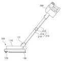
도 1은 본 고안의 일 실시예에 따른 물걸레 청소기 헤드가 장착된 진공청소기를 도시한 도면이고, 도 2는 본 고안의 일 실시예에 따른 물걸레 청소기 헤드가 장착된 진공청소기의 연장부가 꺾인 상태를 도시한 도면이다.1 is a view showing a vacuum cleaner equipped with a mop cleaner head according to an embodiment of the present invention, and FIG. 2 is a state in which the extension of the vacuum cleaner equipped with a mop cleaner head according to an embodiment of the present invention is bent It is a drawing shown.
도 3은 본 고안의 일 실시예에 따른 물걸레 청소기 헤드의 측면을 도시한 도면이며, 도 4는 본 고안의 일 실시예에 따른 물걸레 청소기 헤드의 평면을 도시한 도면이다. 그리고 도 5는 본 고안의 일 실시예에 따른 물걸레 청소기 헤드의 바닥면을 도시한 도면이다.3 is a view showing a side of a mop cleaner head according to an embodiment of the present invention, and FIG. 4 is a view showing a plane of a mop cleaner head according to an embodiment of the present invention. And Figure 5 is a view showing the bottom surface of the mop cleaner head according to an embodiment of the present invention.
도 1을 참조하면, 본 고안의 일 실시예에 따른 물걸레 청소기 헤드(100)는 도시된 바와 같이, 물걸레 청소기 헤드(100)에 전원이 공급되는 진공청소기의 청소기 본체(200)에 결합시켜 이용할 수 있다.Referring to FIG. 1, the
먼저, 진공청소기는 본 실시예에서, 무선 진공청소기를 예시적으로 도시하였지만, 무선 진공청소기에 한정되는 것은 아니며, 유선 진공청소기의 경우에도 이용될 수 있다. 진공청소기의 청소기 본체(200)는, 내부에 모터가 구비되고, 모터의 구동에 의해 진공을 형성하여 먼지나 이물질을 흡입시킬 수 있다. 그리고 내부에 흡입된 먼지나 이물질을 수용하는 수용함이 구비될 수 있고, 배터리나 상용전원으로부터 전원을 공급받을 수 있다.First, the vacuum cleaner is illustrated in this embodiment as a wireless vacuum cleaner, but is not limited to the wireless vacuum cleaner, and may be used in the case of a wired vacuum cleaner. The cleaner
그리고 진공청소기는 연장부(210)를 포함할 수 있다. 별도로 도시하진 않지만, 연장부(210)에는 청소기 본체(200)와 전기적으로 연결될 수 있는 연장라인이 내부에 연장부(210)의 길이방향을 따라 내장될 수 있다. 이를 위해 연장부(210)는 일 측은 청소기 본체(200)에 결합될 수 있고, 타 측은 본 실시예에 따른 물걸레 청소기 헤드(100)에 연결될 수 있다. 그에 따라 물걸레 청소기 헤드(100)는 청소기 본체(200)와 전기적으로 연결될 수 있다.In addition, the vacuum cleaner may include an
본 실시예에서, 연장부(210)는 도 1 및 도 2에 도시된 바와 같이, 꺾일 수 있으며, 이를 위해 제1 연장부재(212), 제2 연장부재(214) 및 꺾임부재(216)를 포함한다. 제1 연장부재(212)는 일단이 청소기 본체(200)에 결합되고, 타단이 꺾임부재(216)에 연결된다. 제2 연장부재(214)는 일단이 꺾임부재(216)에 연결되며, 타단이 물걸레 청소기 헤드(100)에 결합될 수 있다. 꺾임부재(216)는 제1 연장부재(212) 및 제2 연장부재(214)를 연결하며, 제1 연장부재(212)와 제2 연장부재(214)가 소정의 각도로 꺾이도록(또는 회전되도록) 연결할 수 있다.In this embodiment, the
제1 연장부재(212) 및 제2 연장부재(214)는 각각 소정의 길이를 가지며, 꺾임부재(216)에 의해 연결된다. 본 실시예에서, 꺾임부재(216)는 도시된 바와 같이, 제1 연장부재(212) 및 제2 연장부재(214)가 소정의 각도로 회전할 수 있게 내부에 회전축을 포함한다. 이때, 제1 연장부재(212) 및 제2 연장부재(214)는 일 측 방향으로만 꺾일 수 있는데, 꺾임부재(216)가 제1 연장부재(212)보다 아래쪽에 위치할 수 있는 방향으로만 꺾일 수 있다. 즉, 도 2에 도시된 바와 같이, 제2 연장부재(214)가 수평 방향에 근접하고, 제1 연장부재(212)가 수직 방향에 근접하도록 꺾일 때, 꺾임부재(216)의 위치는 제1 연장부재(212)의 아래쪽에 위치할 수 있다. 여기서, 제1 연장부재(212)와 제2 연장부재(214)가 꺾임에 따라 제1 연장부재(212) 및 제2 연장부재(214)가 이루는 각도(θ)는 약 90도 이상 180도 이하일 수 있다.The
물걸레 청소기 헤드(100)는, 헤드 본체부(110), 회전부(120), 걸레(130) 및 브러시(170)를 포함한다.The
헤드 본체부(110)는, 소정의 두께를 가지며 내부에 두 개의 회전모터(125)가 구비될 수 있다. 두 개의 회전모터(125)는 청소기 본체(200)에서 공급된 전원에 의해 구동될 수 있으며, 청소기 본체(200)에서 진공 흡입을 위해 전원을 ON할 때, 같이 구동될 수 있다. 그리고 청소기 본체(200)에서 흡입력의 조절이 이루어지는 경우, 흡입력 조절과 연동하여 회전모터(125)의 구동 속도도 조절될 수 있다.The
즉, 청소기 본체(200)에서 흡입력이 세지면 그에 따라 회전모터(125)의 구동속도도 빨라지고, 청소기 본체(200)에서 흡입력이 약해지면 그에 따라 회전모터(125)의 구동속도도 느려질 수 있다.That is, when the suction power is strong in the
헤드 본체부(110)의 중앙부에는 결합부(112)가 구비될 수 있다. 결합부(112)는 도 1에 도시된 바와 같이, 제2 연장부재(214)에 연결될 수 있다. 이때, 본 실시예에서, 결합부(112)는 헤드 본체부(110)에서 약 90도 각도로 회전할 수 있게 헤드 본체부(110)에 결합될 수 있다. 따라서 도 2에 도시된 바와 같이, 제2 연장부재(214)가 수평 방향으로 위치할 때, 결합부(112)도 헤드 본체부(110)에서 회전되어 수평 방향으로 위치할 수 있다. 따라서 사용자가 청소기 본체(200)의 연장부(210)와 결합부(112)를 연결하여 청소할 때, 결합부(112)가 회전되어 편리하게 청소를 할 수 있다.A
결합부(112)에는 도 3에서와 같이, 하부에 전원연결부(114)가 구비될 수 있다. 전원연결부(114)는 연결부를 통해 청소기 본체(200)의 전원이 연결될 수 있으며, 전원연결부(114)를 통해 물걸레 청소기 헤드(100)에 전원이 공급될 수 있다.The
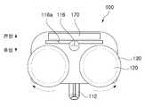
흡입구(116)는 헤드 본체부(110)의 하부에 형성되며, 결합부(112)의 내부와 연결될 수 있다. 도 5를 참조하면, 흡입구(116)는 헤드 본체부(110)의 전방에 치우쳐 배치되며, 후술할 브러시(170)보다는 후방에 배치될 수 있다. 즉, 흡입구(116)는 브러시(170)와 두 개의 회전부(120) 사이에 배치된다. 그리고 흡입구(116)의 주변에 흡입가이드(116a)가 형성될 수 있다. 흡입가이드(116a)는 헤드 본체부(110)의 하면에서 내측으로 형성된 홈의 형상을 가질 수 있으며, 흡입구(116)의 전체 또는 일부를 포함하며, 소정의 길이를 가지도록 형성될 수 있다.The
흡입가이드(116a)는 흡입구(116)를 통해 먼지나 이물질이 보다 용이하게 흡입될 수 있도록 가이드하는 역할을 수행한다. 따라서 흡입가이드(116a)는 두 개의 회전부(120)가 배치된 방향으로 길이를 가지도록 형성될 수 있다. 즉, 흡입가이드(116a)는 청소가 이루어질 때, 물걸레 청소기 헤드(100)의 진행 방향에 수직한 방향으로 길이를 가지도록 헤드 본체부(110)에 형성될 수 있다.The
그에 따라 청소기 본체(200)에서 진공흡입이 이루어지면, 흡입구(116)를 통해 먼지나 이물질 등이 청소기 본체(200)로 이동될 수 있다.Accordingly, when vacuum suction is performed in the
결합버튼(118)은 결합부(112)에 형성되고, 결합부(112)와 제2 연장부재(214)가 결합될 때 분리되지 않도록 할 수 있다. 그리고 사용자가 결합버튼(118)을 눌러 결합부(112)와 제2 연장부재(214)를 분리할 수 있다.
회전부(120)는 헤드 본체부(110)의 하부에 배치되고, 본 실시예에서, 두 개가 구비될 수 있다. 회전부(120)는 헤드 본체부(110)의 내부에 구비된 회전모터(125)와 물리적으로 연결되며, 회전모터(125)의 구동에 따라 회전된다. 본 실시예에서, 회전부(120)는 도 5에 도시된 바와 같이, 하나는 시계 방향으로 회전되고 다른 하나는 반시계방향으로 회전될 수 있다. 이때, 두 개의 회전부(120) 회전 방향은, 헤드 본체부(110)의 중심 부분을 기준으로 헤드 본체부(110)의 전방에서 후방 쪽으로 회전되도록 구성될 수 있다. 그에 따라 헤드 본체부(110)의 앞쪽에서 흡입구(116)가 위치한 방향으로 먼지나 이물질이 이동될 수 있다. 즉, 두 개의 회전부(120)는 평면도상 걸레(130)가 외측에서 내측 방향으로 회전될 수 있다.The
걸레(130)는 도 5에 도시된 바와 같이, 회전부(120)에 결합될 수 있다. 따라서 걸레(130)는 회전부(120)의 회전에 따라 같이 회전될 수 있다. 본 실시예에서, 걸레(130)는 회전부(120)와 벨크로 등으로 결합될 수 있으며, 그 외의 다양한 방식으로 결합될 수 있는데, 걸레(130)와 회전부(120)가 분리될 수 있도록 결합될 수 있다.The
본 실시예에서, 걸레(130)는 제1 외피(132), 제2 외피(134) 및 내부재(136)를 포함한다. 제1 외피(132) 및 제2 외피(134)는 각각 극세사 소재로 제조될 수 있다. 그리고 제1 외피(132) 및 제2 외피(134) 사이에 내부재(136)가 배치될 수 있다. 내부재(136)는 소정의 두께를 가지는 원판 형상으로 형성될 수 있으며, 소정의 물이 흡수될 수 있도록 내부에 다수의 홀이 형성될 수 있다. 이러한 내부재(136)는 천이나 합성수지 등으로 형성될 수 있으며, 원판 형상의 양면에 각각 제1 외피(132) 및 제2 외피(134)가 배치될 수 있다.In this embodiment, the
또한, 내부재(136)는 외부로 노출되지 않을 수 있다. 제1 외피(132) 및 제2 외피(134)가 내부재(136)의 양면에 배치되면서, 내부재(136)의 형상보다 크게 형성되어 제1 외피(132) 및 제2 외피(134)의 가장자리를 따라 재단될 수 있다. 따라서 내부재(136)는 제1 외피(132) 및 제2 외피(134)의 사이에 배치되면서 내부에 배치될 수 있다.In addition, the
이렇게 본 실시예에서, 걸레(130)가 제1 외피(132), 제2 외피(134) 및 내부재(136)를 포함하도록 형성됨에 따라 걸레(130)는 회전부(120)와 벨크로 등으로 결합되지 않을 수 있다. 회전부(120)에는 벨크로의 거친면(갈고리)이 형성될 수 있는데, 앞서 설명한 바와 같이, 걸레(130)는 외측에 벨크로의 부드러운 면이 형성되지 않을 수 있기 때문이다. 그렇다 하더라도 벨크로의 거친면이 걸레(130)의 제1 외피(132) 또는 제2 외피(134)를 잡아주는 역할을 하여 걸레(130)가 회전부(120)에 결합된 상태에서 회전부(120)가 회전하는 동안 걸레(130)가 회전부(120)에서 이탈되지 않을 수 있다. 또한, 헤드 본체부(110)의 무게로 인해 회전부(120)가 걸레(130)를 지속적으로 누르기 때문에 헤드 본체부(110)의 무게에 의해서도 걸레(130)는 회전부(120)에서 이탈되는 것이 방지될 수 있다.Thus, in this embodiment, as the
따라서 본 실시예에서, 걸레(130)는 제1 외피(132) 및 제2 외피(134) 중 어느 쪽으로 청소를 할 수 있고, 제1 외피(132) 및 제2 외피(134) 중 어느 쪽이 회전부(120)에 결합될 수 있다.Therefore, in this embodiment, the
브러시(170)는 헤드 본체부(110)의 하면에 배치되고, 흡입가이드(116a)의 전방에 배치된다. 브러시(170)는 도시된 바와 같이, 소정의 길이를 가지며, 길이 방향을 따라 배치된 회전축에 의해 회전될 수 있도록 원기둥 형상을 가질 수 있다. 즉, 브러시(170)는 회전축을 기준으로 회전할 수 있으며, 외주면을 따라 다수의 솔이 형성될 수 있다. 따라서 브러시(170)가 회전함에 따라 외주면에 형성된 다수의 솔에 의해 먼지나 이물질이 헤드 본체부(110)의 후방 측으로 이동할 수 있고, 후방 측으로 이동된 먼지나 이물질이 흡입가이드(116a)를 통해 흡입구(116)로 흡입될 수 있다.The
즉, 브러시(170)의 후방에 흡입가이드(116a)가 배치되고, 흡입가이드(116a)는 브러시(170)의 길이보다 같거나 길게 형성될 수 있어, 브러시(170)를 통해 전달되는 먼지나 이물질이 흡입구(116)를 통해 흡입되도록 가이드할 수 있다.That is, the
본 실시예에서, 브러시(170)는 별도의 동력이 없이 사용자가 헤드 본체부(100)를 전방으로 이동시킬 때, 청소하고자 하는 바닥면과의 마찰에 의해 회전될 수 있다. 하지만, 이에 한정되는 것은 아니며, 브러시(170)에 별도의 모터가 장착되며, 회전부(120)가 회전모터(125)에 의해 회전될 때, 브러시(170)에 장착된 모터도 구동되어 브러시(170)가 회전되도록 구동될 수 있다. 이때, 모터에는 결합부(122)에 형성된 전원연결부(114)를 통해 공급된 전원이 공급될 수 있다. 또한, 회전모터(125)가 구동될 때, 브러시(170)는 헤드 본체부(110)에 배치된 두 개의 회전모터(125) 중 어느 하나 이상과 기어 등으로 연결될 수 있다. 그에 따라 회전모터(125)의 구동에 의해 브러시(170)가 회전될 수 있다.In this embodiment, the
위에서 설명한 바와 같이 본 고안에 대한 구체적인 설명은 첨부된 도면을 참조한 실시예에 의해서 이루어졌지만, 상술한 실시예는 본 고안의 바람직한 예를 들어 설명하였을 뿐이므로, 본 고안이 상기 실시예에만 국한되는 것으로 이해돼서는 안 되며, 본 고안의 권리범위는 후술하는 청구범위 및 그 등가개념으로 이해되어야 할 것이다.As described above, the detailed description of the present invention was made by an embodiment referring to the accompanying drawings, but the above-described embodiment is only described as a preferred example of the present design, and the present design is limited to the above embodiment only. It should not be understood, and the scope of rights of the present invention should be understood as the following claims and equivalent concepts.
100: 물걸레 청소기 헤드
110: 헤드 본체부
112: 결합부
114: 전원연결부
116: 흡입구
116a: 흡입가이드
118: 결합버튼
120: 회전부
125: 회전모터
130: 걸레
132: 제1 외피
134: 제2 외피
136: 내부재
170: 브러시
200: 청소기 본체
210: 연장부
212: 제1 연장부재
214: 제2 연장부재
216: 꺾임부재100: mop cleaner head
110: head body
112: coupling portion
114: power connection
116: inlet
116a: Suction Guide
118: combine button
120: rotating part
125: rotary motor
130: mop
132: first envelope
134: second envelope
136: interior material
170: brush
200: cleaner body
210: extension
212: first extension member
214: second extension member
216: bending member
Claims (9)
Translated fromKorean상기 헤드 본체부의 하부에 배치되고, 상기 하나 이상의 회전모터의 구동에 의해 회전되며, 각각 걸레가 결합되는 한 쌍의 회전부; 및
상기 헤드 본체부와 청소기 본체를 연결하도록 소정의 길이를 갖는 연장부를 포함하고,
상기 헤드 본체부의 하면에는 상기 청소기 본체의 구동에 의해 상기 헤드 본체부 하부의 먼지나 이물질이 흡입되기 위한 흡입구가 형성되며,
상기 연장부는 상기 흡입구를 통해 흡입된 먼지나 이물질이 상기 청소기 본체로 이송시키기 위해 내부에 중공이 형성되고, 중간 부분이 소정의 각도로 꺾이도록 형성된 물걸레 청소기 헤드.One side is provided with a coupling portion for connecting to the cleaner body, and the head main body portion provided with at least one rotary motor driven by the power supplied from the cleaner body and supplied with power through the power connection formed in the coupling portion ;
A pair of rotating parts disposed under the head body part, being rotated by driving of the one or more rotating motors, and each mop being coupled; And
It includes an extension having a predetermined length to connect the head body portion and the cleaner body,
A suction port for suctioning dust or foreign substances under the head body is formed on the lower surface of the head body by driving the cleaner body.
The extension part is a mop cleaner head formed with a hollow formed therein and a middle portion bent at a predetermined angle to transfer dust or foreign substances sucked through the suction port to the cleaner body.
상기 청소기 본체에 결합되며, 중공이 형성되고, 소정의 길이를 갖는 제1 연장부재;
상기 결합부에 결합되고, 중공이 형성되며, 소정의 길이를 갖는 제2 연장부재; 및
상기 제2 연장부재가 상기 제1 연장부재에서 소정의 각도로 꺾이도록 상기 제1 및 제2 연강부재를 연결하는 꺾임부재를 포함하는 물걸레 청소기 헤드.The method according to claim 1, wherein the extension,
A first extension member coupled to the cleaner body, the hollow being formed, and having a predetermined length;
A second extension member coupled to the coupling portion, the hollow being formed, and having a predetermined length; And
A mop cleaner head including a bending member connecting the first and second mild steel members so that the second extending member is bent at a predetermined angle from the first extending member.
상기 꺾임부재에 의해 상기 제1 및 제2 연장부재는 90도 이상 180 이하의 각도로 꺾이는 물걸레 청소기 헤드.The method according to claim 2,
The first and second extension members are mop cleaner heads bent at an angle of 90 degrees or more and 180 degrees or less by the bending member.
상기 제1 및 제2 연장부재는 상기 꺾임부재가 상기 청소기 본체의 하부에 위치하도록 꺾이는 물걸레 청소기 헤드.The method according to claim 1,
The first and second extension members are water mop cleaner heads that are bent so that the bending member is located at the bottom of the cleaner body.
상기 한 쌍의 회전부 각각은 상기 헤드 본체부의 전방 외측에서 내측 방향으로 회전되며, 서로 반대 방향으로 회전되는 물걸레 청소기 헤드.The method according to claim 1,
Each of the pair of rotating parts is a mop cleaner head that is rotated in an inward direction from the front outside of the head body, and rotated in opposite directions.
상기 헤드 본체부의 하면에 배치되되, 상기 흡입구의 전방에 배치되고, 상기 헤드 본체부에서 회전할 수 있도록 배치된 브러시를 더 포함하고,
상기 브러시는 소정의 길이를 가지며, 길이 방향으로 배치된 회전축을 따라 회전할 수 있도록 상기 헤드 본체부에 배치된 물걸레 청소기 헤드.The method according to claim 1,
It is disposed on the lower surface of the head body portion, is disposed in front of the suction port, and further includes a brush disposed to be rotatable in the head body portion,
The brush has a predetermined length, a mop cleaner head disposed in the head body portion to be rotated along a rotation axis disposed in the longitudinal direction.
상기 헤드 본체부의 하면에는 상기 흡입구에 인접하게 소정의 길이로 홈의 형상으로 흡입가이드가 형성된 물걸레 청소기 헤드.The method according to claim 6,
A water mop cleaner head having a suction guide in a shape of a groove having a predetermined length adjacent to the suction port on the lower surface of the head body.
상기 흡입가이드가 형성된 길이는 상기 브러시의 길이보다 길게 형성된 물걸레 청소기 헤드.The method according to claim 7,
The length of the suction guide formed is a mop cleaner head formed longer than the length of the brush.
상기 걸레는 일면 및 타면 중 선택적으로 상기 한 쌍의 회전부에 결합되는 물걸레 청소기 헤드.The method according to claim 1,
The mop is a mop cleaner head is selectively coupled to the rotating portion of the pair of one side and the other side.
Priority Applications (1)
| Application Number | Priority Date | Filing Date | Title |
|---|---|---|---|
| KR2020180005886UKR20200001393U (en) | 2018-12-18 | 2018-12-18 | Head of wet cleaner |
Applications Claiming Priority (1)
| Application Number | Priority Date | Filing Date | Title |
|---|---|---|---|
| KR2020180005886UKR20200001393U (en) | 2018-12-18 | 2018-12-18 | Head of wet cleaner |
Publications (1)
| Publication Number | Publication Date |
|---|---|
| KR20200001393Utrue KR20200001393U (en) | 2020-06-26 |
Family
ID=71120795
Family Applications (1)
| Application Number | Title | Priority Date | Filing Date |
|---|---|---|---|
| KR2020180005886UAbandonedKR20200001393U (en) | 2018-12-18 | 2018-12-18 | Head of wet cleaner |
Country Status (1)
| Country | Link |
|---|---|
| KR (1) | KR20200001393U (en) |
Cited By (1)
| Publication number | Priority date | Publication date | Assignee | Title |
|---|---|---|---|---|
| KR20230057655A (en) | 2021-10-22 | 2023-05-02 | 최광순 | Smart vibration cleaner |
Citations (1)
| Publication number | Priority date | Publication date | Assignee | Title |
|---|---|---|---|---|
| KR20180100891A (en) | 2017-03-02 | 2018-09-12 | 홍기남 | wireless electrical cleaner with damp cloth |
- 2018
- 2018-12-18KRKR2020180005886Upatent/KR20200001393U/ennot_activeAbandoned
Patent Citations (1)
| Publication number | Priority date | Publication date | Assignee | Title |
|---|---|---|---|---|
| KR20180100891A (en) | 2017-03-02 | 2018-09-12 | 홍기남 | wireless electrical cleaner with damp cloth |
Cited By (1)
| Publication number | Priority date | Publication date | Assignee | Title |
|---|---|---|---|---|
| KR20230057655A (en) | 2021-10-22 | 2023-05-02 | 최광순 | Smart vibration cleaner |
Similar Documents
| Publication | Publication Date | Title |
|---|---|---|
| JP3737458B2 (en) | Suction brush assembly for vacuum cleaner with rotating roller for tapping | |
| KR100493492B1 (en) | Surface cleaning apparatus | |
| US8020236B2 (en) | Floor sweeper with cloth cleaning pad | |
| TWI583338B (en) | Dispenser for cleaning machines | |
| US20170354303A1 (en) | Side brush and robotic cleaner | |
| KR20100093325A (en) | Brush assembly of vacuum cleaner | |
| PT2449937T (en) | Bare floor vacuum cleaner | |
| KR200489361Y1 (en) | Head of wet cleaner | |
| CN101152066B (en) | Duct collector head and electric dust collector using the same | |
| KR20150129426A (en) | Robot cleaner | |
| US20170290487A1 (en) | Dusting device for cleaning machine | |
| JP2020517340A (en) | Cleaning device having combing unit for removing dust from cleaning roller | |
| KR20200001393U (en) | Head of wet cleaner | |
| JP2011177214A (en) | Floor suction tool of vacuum cleaner | |
| KR200485335Y1 (en) | Electrical vacuum cleaner with damp cloth | |
| KR101425928B1 (en) | A Vacuum cleaner with mop | |
| CN109561801B (en) | Vacuum cleaner nozzle and vacuum cleaner | |
| TWI576078B (en) | With dust and dust removal function of the dust removal device | |
| JP5147797B2 (en) | Vacuum cleaner mouthpiece and vacuum cleaner | |
| JP5622830B2 (en) | Vacuum cleaner mouthpiece | |
| JPH0637806Y2 (en) | Vacuum cleaner suction tool | |
| KR200160840Y1 (en) | Vacuum cleaner | |
| KR20200001988U (en) | Head of wet cleaner | |
| JP7496383B2 (en) | Suction nozzle and vacuum cleaner equipped with same | |
| KR200150055Y1 (en) | Vacuum cleaner |
Legal Events
| Date | Code | Title | Description |
|---|---|---|---|
| UA0108 | Application for utility model registration | Comment text:Application for Utility Model Registration Patent event code:UA01011R08D Patent event date:20181218 | |
| UA0201 | Request for examination | ||
| UA0301 | Request for accelerated examination | Comment text:[Request for Accelerated Examination] Document of Request for Examination(Accelerated Examination) Patent event date:20181219 Patent event code:UA03012R01D Comment text:Application for Utility Model Registration Patent event date:20181218 Patent event code:UA03011R01I | |
| UE0902 | Notice of grounds for rejection | Comment text:Notification of reason for refusal Patent event code:UE09021S01D Patent event date:20190226 | |
| UE0601 | Decision on rejection of utility model registration | Comment text:Decision to Refuse Application Patent event code:UE06011S01D Patent event date:20190813 | |
| UX0901 | Re-examination | Patent event date:20190813 Comment text:Decision to Refuse Application Patent event code:UX09011S01I Patent event date:20190527 Comment text:Amendment to Specification, etc. Patent event code:UX09012R01I Patent event date:20181219 Comment text:Amendment to Specification, etc. Patent event code:UX09012R01I | |
| UX0701 | Decision of registration after re-examination | Patent event date:20191030 Patent event code:UX07013S01D Comment text:Decision to Grant Registration Patent event date:20191014 Patent event code:UX07012R01I Comment text:Amendment to Specification, etc. Patent event date:20190813 Patent event code:UX07011S01I Comment text:Decision to Refuse Application Patent event date:20190527 Patent event code:UX07012R01I Comment text:Amendment to Specification, etc. Patent event date:20181219 Patent event code:UX07012R01I Comment text:Amendment to Specification, etc. | |
| UG1501 | Laying open of application | ||
| UC1904 | Unpaid initial registration fee |