KR20200001358U - Fence cap - Google Patents
Fence capDownload PDFInfo
- Publication number
- KR20200001358U KR20200001358UKR2020180005823UKR20180005823UKR20200001358UKR 20200001358 UKR20200001358 UKR 20200001358UKR 2020180005823 UKR2020180005823 UKR 2020180005823UKR 20180005823 UKR20180005823 UKR 20180005823UKR 20200001358 UKR20200001358 UKR 20200001358U
- Authority
- KR
- South Korea
- Prior art keywords
- light
- unit
- clasp
- main body
- coupled
- Prior art date
- Legal status (The legal status is an assumption and is not a legal conclusion. Google has not performed a legal analysis and makes no representation as to the accuracy of the status listed.)
- Granted
Links
- 230000005611electricityEffects0.000claimsabstractdescription15
- 238000010248power generationMethods0.000claimsdescription13
- 238000010168coupling processMethods0.000claimsdescription10
- 230000008878couplingEffects0.000claimsdescription9
- 238000005859coupling reactionMethods0.000claimsdescription9
- 238000003780insertionMethods0.000claimsdescription7
- 230000037431insertionEffects0.000claimsdescription7
- 238000000034methodMethods0.000claimsdescription3
- 238000000926separation methodMethods0.000abstractdescription3
- 230000003287optical effectEffects0.000abstractdescription2
- 238000009434installationMethods0.000description6
- 230000000694effectsEffects0.000description4
- 238000012986modificationMethods0.000description4
- 230000004048modificationEffects0.000description4
- RYGMFSIKBFXOCR-UHFFFAOYSA-NCopperChemical compound[Cu]RYGMFSIKBFXOCR-UHFFFAOYSA-N0.000description2
- 229910052802copperInorganic materials0.000description2
- 239000010949copperSubstances0.000description2
- 230000014509gene expressionEffects0.000description2
- 238000002347injectionMethods0.000description2
- 239000007924injectionSubstances0.000description2
- 239000000463materialSubstances0.000description2
- 239000007769metal materialSubstances0.000description2
- 238000006467substitution reactionMethods0.000description2
- JHBVPKZLIBDTJR-UHFFFAOYSA-N1,2-dichloro-4-(3-chlorophenyl)benzeneChemical compoundClC1=CC=CC(C=2C=C(Cl)C(Cl)=CC=2)=C1JHBVPKZLIBDTJR-UHFFFAOYSA-N0.000description1
- 230000004308accommodationEffects0.000description1
- NIXOWILDQLNWCW-UHFFFAOYSA-Nacrylic acid groupChemical groupC(C=C)(=O)ONIXOWILDQLNWCW-UHFFFAOYSA-N0.000description1
- 229910052782aluminiumInorganic materials0.000description1
- XAGFODPZIPBFFR-UHFFFAOYSA-NaluminiumChemical compound[Al]XAGFODPZIPBFFR-UHFFFAOYSA-N0.000description1
- 230000005540biological transmissionEffects0.000description1
- 238000013461designMethods0.000description1
- 238000005516engineering processMethods0.000description1
- 238000012423maintenanceMethods0.000description1
- 230000036651moodEffects0.000description1
- 238000000465mouldingMethods0.000description1
- 239000000843powderSubstances0.000description1
- 230000002265preventionEffects0.000description1
- 230000000630rising effectEffects0.000description1
- 229920003002synthetic resinPolymers0.000description1
- 239000000057synthetic resinSubstances0.000description1
- 239000012780transparent materialSubstances0.000description1
- 239000002023woodSubstances0.000description1
Images


Classifications
- E—FIXED CONSTRUCTIONS
- E01—CONSTRUCTION OF ROADS, RAILWAYS, OR BRIDGES
- E01F—ADDITIONAL WORK, SUCH AS EQUIPPING ROADS OR THE CONSTRUCTION OF PLATFORMS, HELICOPTER LANDING STAGES, SIGNS, SNOW FENCES, OR THE LIKE
- E01F15/00—Safety arrangements for slowing, redirecting or stopping errant vehicles, e.g. guard posts or bollards; Arrangements for reducing damage to roadside structures due to vehicular impact
- E01F15/02—Continuous barriers extending along roads or between traffic lanes
- E01F15/04—Continuous barriers extending along roads or between traffic lanes essentially made of longitudinal beams or rigid strips supported above ground at spaced points
- H—ELECTRICITY
- H02—GENERATION; CONVERSION OR DISTRIBUTION OF ELECTRIC POWER
- H02S—GENERATION OF ELECTRIC POWER BY CONVERSION OF INFRARED RADIATION, VISIBLE LIGHT OR ULTRAVIOLET LIGHT, e.g. USING PHOTOVOLTAIC [PV] MODULES
- H02S20/00—Supporting structures for PV modules
- H02S20/20—Supporting structures directly fixed to an immovable object
- H02S20/21—Supporting structures directly fixed to an immovable object specially adapted for motorways, e.g. integrated with sound barriers
- H—ELECTRICITY
- H02—GENERATION; CONVERSION OR DISTRIBUTION OF ELECTRIC POWER
- H02S—GENERATION OF ELECTRIC POWER BY CONVERSION OF INFRARED RADIATION, VISIBLE LIGHT OR ULTRAVIOLET LIGHT, e.g. USING PHOTOVOLTAIC [PV] MODULES
- H02S40/00—Components or accessories in combination with PV modules, not provided for in groups H02S10/00 - H02S30/00
- H02S40/30—Electrical components
- H02S40/38—Energy storage means, e.g. batteries, structurally associated with PV modules
- Y—GENERAL TAGGING OF NEW TECHNOLOGICAL DEVELOPMENTS; GENERAL TAGGING OF CROSS-SECTIONAL TECHNOLOGIES SPANNING OVER SEVERAL SECTIONS OF THE IPC; TECHNICAL SUBJECTS COVERED BY FORMER USPC CROSS-REFERENCE ART COLLECTIONS [XRACs] AND DIGESTS
- Y02—TECHNOLOGIES OR APPLICATIONS FOR MITIGATION OR ADAPTATION AGAINST CLIMATE CHANGE
- Y02E—REDUCTION OF GREENHOUSE GAS [GHG] EMISSIONS, RELATED TO ENERGY GENERATION, TRANSMISSION OR DISTRIBUTION
- Y02E10/00—Energy generation through renewable energy sources
- Y02E10/50—Photovoltaic [PV] energy
- Y—GENERAL TAGGING OF NEW TECHNOLOGICAL DEVELOPMENTS; GENERAL TAGGING OF CROSS-SECTIONAL TECHNOLOGIES SPANNING OVER SEVERAL SECTIONS OF THE IPC; TECHNICAL SUBJECTS COVERED BY FORMER USPC CROSS-REFERENCE ART COLLECTIONS [XRACs] AND DIGESTS
- Y02—TECHNOLOGIES OR APPLICATIONS FOR MITIGATION OR ADAPTATION AGAINST CLIMATE CHANGE
- Y02E—REDUCTION OF GREENHOUSE GAS [GHG] EMISSIONS, RELATED TO ENERGY GENERATION, TRANSMISSION OR DISTRIBUTION
- Y02E70/00—Other energy conversion or management systems reducing GHG emissions
- Y02E70/30—Systems combining energy storage with energy generation of non-fossil origin
Landscapes
- Engineering & Computer Science (AREA)
- Architecture (AREA)
- Civil Engineering (AREA)
- Structural Engineering (AREA)
- Refuge Islands, Traffic Blockers, Or Guard Fence (AREA)
- Road Signs Or Road Markings (AREA)
Abstract
Translated fromKoreanDescription
Translated fromKorean본 고안은 휀스 지주 상단에 결합되는 휀스 캡에 관한 것으로서, 보다 상세하게는 휀스 지주가 결합되는 본체와, 상기 본체에 구비되는 투광유닛, 상기 투광유닛에 구비되어 태양광을 통하여 전기를 생성하는 태양광유닛과 이 전기를 이용하여 빛을 발산하는 발광유닛으로 구성되되, 상기 투광유닛이 상기 본체 중공부에 결합될 때, 투광유닛 외면에 구비된 제1 걸쇠부가 상기 중공부 내측면을 지지하도록 구성하여 임의로 투광유닛이 본체로부터 분리되는 것을 방지하여 분실 또는 도난되는 문제를 해결할 수 있는 태양광 발전용 휀스 캡에 관한 것이다.The present invention relates to a fence cap coupled to the top of a fence post, and more specifically, a body to which a fence post is coupled, a light transmitting unit provided in the body, and a sun provided in the light transmitting unit to generate electricity through sunlight. It is composed of an optical unit and a light emitting unit that emits light by using this electricity, and when the translucent unit is coupled to the hollow portion of the main body, the first clasp portion provided on the outer surface of the transmissive unit is configured to support the hollow portion inner surface. Therefore, it is possible to prevent the separation of the light transmitting unit from the main body and to solve the problem of being lost or stolen.
일반적으로 휀스는 사람의 보행이나 차량의 운행에 있어서, 안전을 확보하기 위해 차도, 인도, 자전거도로, 산책로 등에 설치되는 것으로, 지면에 미리 정해진 간격으로 설치되는 지주와, 이 지주와 지주 사이에 가로방향으로 설치되는 프레임으로 구성되며, 상기 지주의 상단부에는 지주의 내부로 이물질이나 빗물 등의 유입을 방지하는 한편 미관을 제공하기 위한 캡이 구비되게 된다.In general, a fence is installed on a road, a sidewalk, a bicycle road, a trail, and the like to secure safety in walking or driving a person, and a post installed at predetermined intervals on the ground and a horizontal distance between the post and the post. It is composed of a frame installed in the direction, and a cap for providing aesthetics while preventing foreign matter or rainwater from entering the inside of the support is provided at the upper end of the support.
그러나 상기 캡은 통상 고가의 금속재질로 제작됨에 다라 지주로부터 분리시켜 도난당하는 사례가 빈번이 발생하고 있고, 등록특허 제10-1402181호 "지주캡 이탈방지장치가 구비된 도로용 펜스"는 이를 개선하여 지주캡의 도난을 방지하고 있다.However, since the cap is usually made of an expensive metal material, the case of being stolen by separating it from the prop is frequently occurring, and Patent No. 10-1402181 "Fence for Roads with a Holding Cap Departure Prevention Device" improves it. The holding cap is prevented from being stolen.
구체적으로 상기 종래기술은 지면에 미리 정해진 간격으로 설치되는 지주; 상기 지주에 가로 방향으로 설치되는 가드 프레임; 상기 지주의 상단부에 결합되는 지주캡; 및 상기 지주캡이 상기 지주로부터 이탈되는 것을 방지하기 위한 지주캡 이탈방지장치를 포함하고, 상기 지주캡 이탈방지장치는, 상기 지주캡의 내부에 배치되어 상기 지주캡에 결합되는 지지부재; 상기 지주의 내부에서 상기 지주의 하단 측으로 연장되고 상단부가 상기 지지부재에 걸려지는 연결부재; 및 상기 연결부재의 하단부를 상기 지주에 대해 결속시키는 결속부재를 포함하여 이루어지는 것으로서,Specifically, the prior art supports are installed at predetermined intervals on the ground; A guard frame installed in the horizontal direction on the post; A holding cap coupled to the upper end of the holding; And a holding cap detachment preventing device for preventing the holding cap from being detached from the holding, and the holding cap detachment preventing device comprises a support member disposed inside the holding cap and coupled to the holding cap; A connecting member extending from the inside of the strut to the lower end of the strut and the upper end hanging on the support member; And a binding member that binds the lower end of the connecting member to the support,
지주캡이 지주 하단부에 연결부재를 통해 연결되어 고정되는 구조로, 설치가 매우 번거롭고 지주의 내부에 중공부가 형성되어야만 설치가 가능하다는 문제가 있다.Since the holding cap is connected to and fixed to the lower end of the strut through a connecting member, installation is very cumbersome and there is a problem that installation is possible only when a hollow is formed inside the strut.
또한 근래에는 야간 보행에 도움을 주거나 미관을 수려하게 하기 위하여 빛을 발광시킬 수 있는 지주캡이 다양하게 제시되고 있는 실정이다.In addition, in recent years, a variety of holding caps capable of emitting light in order to help walking at night or to enhance aesthetics have been proposed.
종래기술로는 공개특허 제10-2007-0101740호 "불빛이 발광 되는 휀스용 안전캡"이 있는데,As a related art, there is "Patent No. 10-2007-0101740", a safety cap for a fence that emits light.
상기 종래기술은 지면으로부터 세워지는 수직봉과; 상기 수직봉 사이의 상,하단에 위치하는 수평봉과; 상기 수평봉 사이에 위치시켜 다양한 무늬 모양으로 이루어지는 지지봉 과; 상기 수직봉의 상단에 씌움 결합되는 씌움요소를 갖추고, 이의 상부에 일체로 하여 다양한 장식의 모양을 갖도록 하는 장식요소로 이루어지는 안전캡이 갖추어진 휀스를 형성함에 있어, 상기 안전캡인 장식요소의 내부에 태양열을 흡수 저장할 수 있도록 하는 쏠라셀과; 상기 쏠라셀과 전선으로 연결된 상태에서 장식요소의 외주연에 갖추어진 관통공에 끼움 결합시켜 불빛이 발광 될 수 있도록 하는 발광램프로 이루어지는 안전캡을 제시하고 있다.The prior art is a vertical bar erected from the ground; Horizontal bars located at upper and lower ends between the vertical bars; A support rod formed between the horizontal rods and formed in various patterns; In forming a fence equipped with a safety cap made of a decorative element that has a covering element coupled to the top of the vertical bar and is integrally formed on top of it to have various decorative shapes, inside the decorative element that is the safety cap A solar cell capable of absorbing and storing solar heat; A safety cap made of a luminous lamp is provided that allows light to be emitted by fitting it into a through hole provided on the outer periphery of the decorative element while connected to the solar cell and an electric wire.
그러나 상기 종래기술은 빛의 발광 범위가 측방향으로 한정될 수 밖에 없으며, 태양광패널 등의 고가의 구성요소가 포함된 안전캡이 쉽게 지주로부터 분리될 수 있어 도난의 우려가 발생하는 문제가 있다.However, in the prior art, the light emission range is limited to the lateral direction, and a safety cap including expensive components such as a solar panel can be easily separated from the support, causing a problem of theft. .
또 다른 종래기술로 공개특허 제10-2012-0056333호 "휀스용 지주캡"이 있는데,Another prior art is Patent Publication No. 10-2012-0056333, "The holding cap for Higgs",
상기 종래기술은 지주캡을 사출 성형이 가능한 목분 함유 합성수지재로 제작하되, 성형단계에서 몸체에 형광표시부가 함께 사출 성형되도록 함으로써, 주간에 빛을 축광시켜 야간에 발광시킴으로써 조명등 대용으로 사용이 가능하고, 지주캡에서 은은하게 발광되는 형광조명에 의해 무드 등으로서의 분위기를 연출하게 되며, 설치가 쉽고, 설치비용이 저렴하며, 설치 후에도 유지보수가 간편한 효과를 갖는 지주캡에 관한 것이다.In the prior art, the holding cap is made of a synthetic resin material containing wood powder that can be injection molded, but it is possible to use it as a substitute for lighting by emitting light during the day and emitting light at night by allowing the fluorescent display part to be injection molded together in the molding step. , It is directed to a holding cap that has an effect as a mood or the like by a fluorescence light that is softly emitted from the holding cap, has an effect of easy installation, low installation cost, and easy maintenance even after installation.
그러나 상기 종래기술은 낮에 빛을 축광시켜 야간에 발광시키는 것으로, 비가 오거나 흐린날에는 빛을 축광하지 못하는 문제가 있으며, 이 또한 지주로부터 쉽게 분리가 가능하여 도난의 우려가 발생하는 문제가 있다.However, the prior art is to emit light during the day and emit light at night. There is a problem that light cannot be accumulated on a rainy or cloudy day, and there is also a problem in that it can be easily separated from a prop and cause theft.
나아가 종래기술로 공개실용신안 제20-2015-0004337호 "태양광을 이용한 휀스용 발광 헤드캡"이 있는데,Furthermore, there is a public utility model No. 20-2015-0004337 "Light emitting head cap for Higgs using sunlight" as a prior art.
상기 종래기술은 해드캡(100)은 하측에서 상측으로 내삽되는 끼움홀(111)이 형성되고, 내부에 상기 태양전지판(10)이 구성되며 상측과 상기 끼움홀(111)에 상기 발광모듈(40)이 각각 구성되는 해드부(110)와, 상기 해드부(110)의 하부에서 연장되되 상기 해드부(110) 보다 작은 지름을 가지며 내부에 배터리(30)와 컨트롤러(50)가 각각 구성되는 몸체부(120)와, 상기 몸체부(120)의 하부에서 연장되되 하부에 다수의 끼움부(131)가 형성되어 상기 지주대(200)의 상부에 결합되는 결합부(130)로 구성됨으로써, 지면에 이미 설치된 휀스의 지주대(200) 상부에 개별적으로 선택적으로 탈부착 할 수 있도록 하여 편리성을 부여하면서도 경제적 효율성을 높일 수 있고, 발광모듈(40)이 끼움홀과 커버(112)에 의해 보호될 수 있는 구조로 구성되어 악천후 및 외부요인으로 인해 충격이 발생 시에도 파손을 방지 할 수 있음은 물론, 무엇보다 발광모듈(40)이 발광을 함에 있어서 컨트롤러(50)를 통해 하측 또는 상측 및 동시에 발광할 수 있도록 하되 렌즈부(113)를 통해 증폭되어 발광되도록 하여 야간에 지면으로 비춰져 안전사고를 방지할 수 있는 헤드캡을 제시하고 있다.In the prior art, the head cap 100 has a
그러나 상기 종래기술은 헤드캡을 고정하기 위하여 별도의 고정볼트를 이용하여 지주 내에 고정하는 방식으로 구조가 복잡하여 설치가 번거롭다는 문제가 있다.However, the prior art has a problem in that installation is cumbersome because the structure is complicated in a manner of fixing in the support using a separate fixing bolt to fix the head cap.
따라서 본 고안은 상기 문제를 해결하기 위해 안출한 것으로서,Therefore, the present invention was devised to solve the above problem,
휀스의 지주가 결합되는 본체와, 상기 본체에 형성된 중공부에 끼움결합되는 투광유닛, 상기 투광유닛에 구비되는 태양광유닛 및 만들어진 전기를 이용하여 빛을 발산하는 발광유닛을 구비하여 태양광을 이용하여 빛을 외부로 발산시킬 수 있도록 하며, 특히 상기 투광유닛에 제1 걸쇠부를 더 구비함에 따라 투광유닛이 임의로 본체로부터 분리되는 것을 방지하여 도난사고를 예방하는 태양광 발전용 휀스 캡을 제공함을 목적으로 한다.The main body to which the pillar of the fence is coupled, the light-transmitting unit fitted to the hollow formed in the main body, the solar unit provided in the light-transmitting unit, and the light-emitting unit that emits light using the generated electricity use solar light The purpose of the present invention is to provide a heat generating cap for solar power generation by preventing light theft by preventing the light transmitting unit from being detached from the body, as the light emitting unit further includes a first clasp. Should be
또한 상기 투광유닛이 함체와 덮개로 이루어지되, 이들 또한 결합수단에 의해 걸쇠 고정 방식으로 결합됨에 따라 조립의 편의성을 높임과 동시에 견고하게 함체와 덮개를 고정할 수 있는 태양광 발전용 휀스 캡을 제공함을 목적으로 한다.In addition, the light-transmitting unit is composed of a housing and a cover, but they also provide a solar power cap that can securely fix the housing and cover at the same time as it increases the convenience of assembly as it is combined in a clasp-locking manner by a coupling means. It is aimed at.
나아가 상기 본체의 외면에 하나 또는 둘 이상의 발광공이 구비되어, 상기 발광유닛이 발광공에 결합되어 본체 외면으로 빛을 발산함에 따라 측방향 및 상방향 모두 빛이 발산될 수 있는 태양광 발전용 휀스 캡을 제공함을 또 하나의 목적으로 한다.Furthermore, one or two or more light-emitting holes are provided on the outer surface of the main body, and the light-emitting unit is coupled to the light-emitting hole to emit light to the outer surface of the main body, so that both side and upward directions can emit light. Another object is to provide.
상기와 같은 목적을 달성하기 위하여, 본 고안에 따른 태양광 발전용 휀스 캡은In order to achieve the above object, the Higgs cap for solar power generation according to the present invention is
상부에 중공부가 형성되고, 하부에 휀스의 지주가 결합되도록 삽입공이 형성된 본체;The body is formed with a hollow portion is formed in the upper portion, the insertion hole is formed so that the support of the fence is coupled to the lower portion;
상기 중공부에 결합되는 투광유닛;A light transmitting unit coupled to the hollow portion;
상기 투광유닛에 구비되어, 태양광을 받아 전기를 생성하는 태양광패널과, 상기 태양광패널에 의해 생성된 전기를 모으는 충전지를 포함하는 태양광유닛;A photovoltaic unit provided in the light transmitting unit, the photovoltaic panel receiving sunlight and generating electricity, and a photovoltaic unit including a rechargeable battery collecting electricity generated by the photovoltaic panel;
상기 본체 또는 투광유닛 또는 이들 모두에 구비되어, 상기 충전지에 의해 생성된 전기를 통하여 빛을 발광하는 램프로 이루어지는 발광유닛;A light-emitting unit provided on the main body or the light-transmitting unit or both, and comprising a lamp that emits light through electricity generated by the rechargeable battery;
을 포함하여 이루어지되,Including, but
상기 투광유닛에는 상기 본체의 중공부 내측 테두리에 걸림 고정되는 제1 걸쇠부가 더 구비되어, 상기 투광유닛이 상기 중공부로부터 임의로 분리되는 것을 방지하는 것을 특징으로 한다.The light transmitting unit is further provided with a first clasp part which is fastened to the inner edge of the hollow part of the main body, thereby preventing the light transmitting unit from being arbitrarily separated from the hollow part.
이상과 같이 본 고안에 따른 태양광 발전용 휀스 캡은As described above, the Higgs cap for solar power generation according to the present invention is
중공부가 형성된 본체와, 투광유닛, 태양광유닛 및 발광유닛을 구비하여 태양광을 이용하여 빛을 본체 외부로 발산시켜 야간 보행 시 시야를 확보할 수 있고, 미관을 수려하게 할 수 있으며, 특히 상기 투광유닛이 제1 걸쇠부를 구비하여 중공부 내측을 지지함에 따라 임의로 투광유닛을 본체 상부방향으로 분리시킬 수 없도록 함으로서 도난방지 효과를 기대할 수 있다.The body is provided with a hollow portion, and a light emitting unit, a solar unit, and a light emitting unit are provided to radiate light to the outside of the body using sunlight, thereby ensuring visibility when walking at night, and making aesthetics beautiful. The anti-theft effect can be expected by preventing the light-transmitting unit from being detached in the upper direction of the body, as the light-transmitting unit has a first clasp and supports the inside of the hollow.
또한 투광유닛이 함체와 덮개로 구성되되, 이들 또한 제2 걸쇠부로 이루어지는 결합수단을 이용하여 고정함에 따라 손쉽게 결합하되 견고하게 고정될 수 있어 내구성을 향상시키고, 상기 투광유닛 내부에 태양광유닛을 구비함에 따라 태양광유닛으로 이물질이 유입되는 것을 방지할 수 있는 효과가 있다.In addition, the light-transmitting unit is composed of a housing and a cover, and they are also easily coupled, but can be securely fixed as they are fixed using a coupling means made of a second clasp, thereby improving durability, and providing a solar unit inside the light-transmitting unit. Accordingly, it is possible to prevent foreign matter from entering the solar unit.
나아가 발광유닛이 본체 외면에 복수개로 구비됨에 따라 다양한 빛을 본체의 측방향 또는 상방향 또는 이들 모두의 방향으로 발산됨에 따라 시야 확보 및 미관을 수려하게 하고, 다양한 조명효과를 연출할 수 있는 특징이 있다.Furthermore, as a plurality of light emitting units are provided on the outer surface of the main body, as various light is emitted in the lateral or upward direction of the main body or in both directions, it is possible to secure a field of view and aesthetics, and to produce various lighting effects. .
도 1은 본 고안에 따른 태양광 발전용 휀스 캡의 결합 사시도
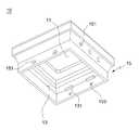
도 2는 본 고안에 따른 태양광 발전용 휀스 캡의 분해 사시도
도 3은 본 고안에 따른 태양광 발전용 휀스 캡의 결합 단면도
도 4는 본 고안에 따른 태양광 발전용 휀스 캡의 본체의 배면도
도 5는 본 고안에 따른 태양광 발전용 휀스 캡의 투광유닛의 배면도1 is a combined perspective view of a fence cap for solar power generation according to the present invention
Figure 2 is an exploded perspective view of a fence cap for solar power generation according to the present invention
Figure 3 is a cross-sectional view of the coupling of the Higgs cap for solar power generation according to the present invention
Figure 4 is a rear view of the body of the fence cap for solar power generation according to the present invention
5 is a rear view of the light transmitting unit of the Higgs cap for solar power generation according to the present invention
이하 첨부된 도면을 참고하여 본 고안을 상세히 설명하도록 한다.Hereinafter, the present invention will be described in detail with reference to the accompanying drawings.
본 고안은 다양한 변경을 가할 수 있고 여러 가지 형태를 가질 수 있는 바, 구현예(態樣, aspect)(또는 실시예)들을 본문에 상세하게 설명하고자 한다. 그러나 이는 본 고안을 특정한 개시 형태에 대해 한정하려는 것이 아니며, 본 고안의 사상 및 기술범위에 포함되는 모든 변경, 균등물 내지 대체물을 포함하는 것으로 이해되어야 한다.Since the present design can apply various changes and can have various forms, it is intended to describe in detail the embodiments (態樣, aspect) (or embodiments) in the text. However, this is not intended to limit the present invention to a specific form of disclosure, and it should be understood that all modifications, equivalents, or substitutes included in the spirit and scope of the present invention are included.
각 도면에서 동일한 참조부호, 특히 십의 자리 및 일의 자리 수, 또는 십의 자리, 일의 자리 및 알파벳이 동일한 참조부호는 동일 또는 유사한 기능을 갖는 부재를 나타내고, 특별한 언급이 없을 경우 도면의 각 참조부호가 지칭하는 부재는 이러한 기준에 준하는 부재로 파악하면 된다.The same reference numbers in each drawing, especially the number of tens and ones, or the same number of tens, ones and alphabets refer to members having the same or similar functions, and unless otherwise specified, The member indicated by the reference numeral can be understood as a member conforming to these standards.
또 각 도면에서 구성요소들은 이해의 편의 등을 고려하여 크기나 두께를 과장되게 크거나(또는 두껍게) 작게(또는 얇게) 표현하거나, 단순화하여 표현하고 있으나 이에 의하여 본 고안의 보호범위가 제한적으로 해석되어서는 안 된다.In addition, in each drawing, the elements are exaggeratedly large (or thick) or smallly (or thinly) or simplified to express the size or thickness in consideration of convenience, etc., thereby limiting the scope of the present invention. It should not be.
본 명세서에서 사용한 용어는 단지 특정한 구현예(태양, 態樣, aspect)(또는 실시예)를 설명하기 위해 사용된 것으로, 본 고안을 한정하려는 의도가 아니다. 단수의 표현은 문맥상 명백하게 다르게 뜻하지 않는 한, 복수의 표현을 포함한다. 본 출원에서, ~포함하다~ 또는 ~이루어진다~ 등의 용어는 명세서 상에 기재된 특징, 숫자, 단계, 동작, 구성요소, 부분품 또는 이들을 조합한 것이 존재함을 지정하려는 것이지, 하나 또는 그 이상의 다른 특징들이나 숫자, 단계, 동작, 구성요소, 부분품 또는 이들을 조합한 것들의 존재 또는 부가 가능성을 미리 배제하지 않는 것으로 이해되어야 한다.The terminology used herein is only used to describe a specific embodiment (sun, 態樣, aspect) (or embodiment), and is not intended to limit the present invention. Singular expressions include plural expressions unless the context clearly indicates otherwise. In the present application, terms such as ~include~ or ~consist of~ are intended to designate the existence of features, numbers, steps, operations, components, parts or combinations thereof described in the specification, and one or more other features. It should be understood that the existence or addition possibilities of fields or numbers, steps, actions, components, parts or combinations thereof are not excluded in advance.
다르게 정의되지 않는 한, 기술적이거나 과학적인 용어를 포함해서 여기서 사용되는 모든 용어들은 본 고안이 속하는 기술 분야에서 통상의 지식을 가진 자에 의해 일반적으로 이해되는 것과 동일한 의미를 가지고 있다. 일반적으로 사용되는 사전에 정의되어 있는 것과 같은 용어들은 관련 기술의 문맥 상 가지는 의미와 일치하는 의미를 가지는 것으로 해석되어야 하며, 본 출원에서 명백하게 정의하지 않는 한, 이상적이거나 과도하게 형식적인 의미로 해석되지 않는다.Unless otherwise defined, all terms used herein, including technical or scientific terms, have the same meaning as commonly understood by a person skilled in the art to which this invention belongs. Terms, such as those defined in a commonly used dictionary, should be interpreted to have meanings consistent with meanings in the context of related technologies, and should not be interpreted as ideal or excessively formal meanings unless explicitly defined in the present application. Does not.
본 고안에 따른 태양광 발전용 휀스 캡(C)은 도 1 내지 도 3에 도시된 바와 같이, 본체(10)와, 투광유닛(20), 태양광유닛(30) 및 발광유닛(40)의 구성으로 이루어지며, 휀스를 구성하는 지주 상단부에 결합될 수 있도록 이루어진다.As illustrated in FIGS. 1 to 3, the Higgs cap for solar power generation according to the present invention is composed of a
각각의 구성에 대하여 도 1 내지 도 4를 참고하여 보다 상세하게 설명하면,Referring to Figures 1 to 4 for each configuration in more detail,
먼저, 상기 본체(10)는 상부에 중공부(11)가 형성되고, 하부에 삽입공(13)이 형성된 형상으로, 상기 중공부(11)와 삽입공(13)은 사각형의 형상으로 이루어지도록 도시하였으나, 이는 후술하는 투광유닛(20)이 원형이고 지주가 원형으로 이루어지는 경우에는 그에 맞는 원형의 형상이 될 수 있으며, 그 밖에 다른 형상으로도 구현이 가능하며 이에 권리범위를 제한 해석해서는 안 된다.First, the
상기 본체(10)는 일반적으로 동, 구리, 알루미늄 등의 금속재질로 이루어져 있으며, 상기 본체(10)의 상부, 즉 중공부(11)의 테두리에는 내플랜지부(111)가 형성되어 후술하는 제1 걸쇠부(214)가 내측에서 지지할 수 있도록 한다.The
상기 본체(10)의 외면에는 하나 또는 둘 이상의 발광공(151)이 형성되어 있으며, 이 발광공(151)은 도면에는 본체(10)의 측방향에 형성된 것을 도시하였으나, 본체(10)의 상단부, 즉 상기 내플랜지부(111)에 형성되는 것도 가능하며 그 개수 및 위치는 다양하게 변경될 수 있다.One or more light-emitting
다시 상기 본체(10)는 삽입공(13)을 형성하도록 외벽부(15)가 형성되어 있으며, 상기 발광공(151)이 외벽부(15)에 형성되는 경우를 도시한 것이다.Again, the
상기 외벽부(15)는 설치되는 휀스의 지주 상단부 외측을 감쌀 수 있는 구조로, 즉, 상기 삽입공(13)에 지주가 내삽되는 구조로 이루어지게 된다.The
이 때 상기 본체(10)의 내벽면, 즉 상기 외벽부(15)의 내측면에는 상기 지주의 상단부에 밀착되어 지주의 상단부가 더 이상 인입되지 않도록 하는 지지돌기(131)가 복수개로 구비되게 된다.At this time, the inner wall surface of the
아울러, 상기 본체(10)를 지주에 결합하는 경우, 상기 지주와 본체(10)를 고정할 필요가 있으며, 이를 위하여 상기 외벽부(15)에는 복수개의 볼트공(153)이 더 구비되어 상기 지주와 볼트결합을 통하여 본체(10)를 지주에 견고하게 고정할 수 있는 특징을 갖는다.In addition, when the
본 고안은 발광유닛(40)을 구비하여 후술하는 태양광유닛(30)을 통해 생성된 전기를 이용하여 빛을 외부로 발산하고 있으며, 이 발광유닛(40)은 램프로 이루어져 있고, 이 램프가 상기 발광공(151)에 결합되어 빛을 외부로 발산할 수 있으며, 상기 발광유닛(40)은 별도의 전원선을 통하여 상기 태양광유닛(30)과 연결되어 전기를 공급받을 수 있게 된다.The present invention is provided with a light emitting unit (40) to emit light to the outside using electricity generated through the solar unit 30 to be described later, the
본 발명은 고가의 태양광유닛(30)의 도난을 방지하고, 태양광유닛(30)으로 이물질이 유입되는 것을 방지하기 위하여 별도의 투광유닛(20)을 더 구비하고 있으며, 도 2 내지 도 5를 참조하여 상기 투광유닛(20)에 대하여 보다 상세하게 설명하도록 한다.The present invention further prevents theft of the expensive solar unit 30, and further comprises a separate light-transmitting
먼저, 상기 투광유닛(20)은 함체(21)와, 상기 함체(21)를 덮는 덮개(23)로 이루어져 있으며,First, the
상기 함체(21)는 태양광유닛(30)이 내장될 수 있도록 수용부(211)가 형성되어 있으며, 상기 함체(21)의 상단부는 미관을 수려하게 하고, 태양 빛을 보다 효과적으로 집광시킬 수 있도록 다각뿔의 형상을 이루고 있다.The
물론, 상기 함체(21)는 투명한 재질, 바람직하게는 아크릴 재질로 이루어져 빛의 투과를 방해하지 않도록 하는 것이 바람직하다.Of course, the
상기 함체(21)는 상기 본체(10)의 중공부(11)에 결합되는 것으로서, 중공부(11)에 결합되어 상기 함체(21)의 상단부가 본체(10) 상부로 노출될 수 있도록 이루어지며,The
이 때 상기 함체(21)에는 제1 걸쇠부(214)가 구비되어 본체(10)의 중공부(11)에 견고하게 고정되고, 임의로 함체(21)를 본체(10) 상부방향으로 분리시킬 수 없도록 하여 도난을 방지하고 있다.At this time, the
상기 제1 걸쇠부(214)에 대하여 설명하면, 상기 제1 걸쇠부(214)는 상기 함체(21)의 수용부(211)를 형성하는 내벽부(212)에 형성되어, 상기 함체(21)를 중공부(11)에 결합하면, 상기 본체(10)의 내측, 보다 정확하게는 상기 내플랜지부(111)의 내측을 지지함으로서 분리되는 것을 방지하도록 이루어진다.When the
보다 구체적으로는 상기 함체(21)의 내벽부(212)에는 걸쇠형성공(213)이 구비되고, 이 걸쇠형성공(213)에 상기 제1 걸쇠부(214)가 일단만 함체(21)에 연결된 채 구비되게 된다.More specifically, the
먼저, 상기 제1 걸쇠부(214)는 제1 기둥부(214A)와, 상기 제1 기둥부(214A)로부터 외측으로 돌출된 형상의 제1 걸림부(214B)로 이루어져 있으며, 이 제1 걸림부(214B)는 직선형의 제1 단턱부(214Ba)와 제1 경사부(214Bb)로 구성된다.First, the
이 때 상기 제1 기둥부(214A)는 상기 함체(21)의 내벽부(212)에 연장된 형상을 이루고 있으며, 제1 기둥부(214A)는 함체(21)와 연장된 부분을 제외하고는 상기 걸쇠형성공(213) 내에 비접촉되는 형상으로 이루어진다.At this time, the
즉, 이러한 구조에 의해, 상기 제1 걸쇠부(214)는 탄성력이 형성되게 되며, 함체(21)를 중공부(11)에 삽입할 때, 중공부(11)의 테두리가 상기 제1 경사부(214Bb)를 따라 상승하면, 자연스럽게 제1 걸쇠부(214)가 내측으로 탄성인입되고, 상기 중공부(11)의 테두리가 제1 경사부(214Bb) 단부의 제1 단턱부(214Ba)에 위치하면, 다시 상기 제1 걸쇠부(214)가 탄성력에 의해 외측으로 돌출되어 제1 단턱부(214Ba)가 중공부(11) 테두리, 즉 내플랜지부(111) 내측을 지지함에 따라 임의로 투광유닛(20)을 분리시키지 못하도록 구성된다.That is, by such a structure, the
또한 상기 함체(21)의 내벽부(21)에는 걸림단턱부(212A)가 더 형성되어, 이 걸림단턱부(212A)가 상기 본체(10)의 내플랜지부(111) 상면에 밀착됨에 따라 투광유닛(20)이 중공부(11)에 고정된 상태에서 과하게 인입 또는 인출되는 것을 방지하는 역할을 할 수 있다.In addition, a locking
아울러, 상기 함체(21)의 상단부에는 상기 발광유닛(40)이 끼워질 수 있는 발광홈(215)이 더 구비되어, 빛을 상방향으로 더 발산시킬 수 있도록 하며, 상기 발광홈(215)의 형상 및 개수는 다양하게 구현될 수 있으며, 이에 권리범위를 제한 해석해서는 안 된다.In addition, the upper end of the
또한 상기 함체(21)의 상단 테두리에는 태양광유닛(30)의 태양광패널(31)이 안착되는 안착돌기(216)가 더 구비되어 있으며, 이 안착돌기(216)에 의해 상기 태양광패널(31)이 함체(21) 상단 내측에 밀착되는 것을 방지하여 태양광패널(31)의 파손을 방지할 수 있다.In addition, a
상기 투광유닛(20)의 덮개(23)에 대하여 설명하기에 앞서, 상기 태양광유닛(30)에 대하여 설며하면, 먼저 상기 태양광유닛(30)은 태양광을 받아 전기를 생성하는 태양광패널(31)과, 생성된 전기를 충전하는 충전지(35) 및 이들의 흐름을 제어하는 PCB(33)로 이루어지게 되며, 이러한 구성은 종래에 널리 알려진 공지된 기술로 자세한 설명은 생략하도록 한다.Before explaining the
상기 태양광유닛(30)은 상기 투광유닛(20)의 수용부(211)에 위치하는 것으로서, 도 2를 참조하여 투광유닛(20)의 덮개(23)에 대하여 구체적으로 설명하면,The solar unit 30 is located in the receiving
우선 상기 덮개(23)는 상기 수용부(211)를 폐쇄할 수 있도록 이루어지는 것으로서, 상기 함체(21)와의 결합을 위한 제2 걸쇠부(231)가 더 구비되게 된다.First, the
상기 제2 걸쇠부(231)는 상기 제1 걸쇠부(214)와 유사한 형상으로 이루어지는 것으로, 제2 기둥부(231A), 제2 걸림부(231B)로 이루어지고, 상기 제2 걸림부(231B)는 제2 단턱부(231Ba)와 제2 경사부(231Bb)로 구성된다.The
상기 제2 걸쇠부(231)는 상기 함체(21)에 형성되는 걸쇠공(217)에 결합되는 것으로서, 상기 걸쇠공(217)은 상기 걸쇠형성공(213)에 인접하여 구비되는 것으로서, 상기 제2 걸쇠부(231)의 결합방식에 대해서는 상기 제1 걸쇠부(214)의 결합방식과 유사함에 따라 자세한 설명은 생략하도록 한다.The
이 때 상기 제2 걸쇠부(231)는 상기 함체(21) 내측부분으로 진입하여 상기 걸쇠공(217)에 결합되는 구조로 이루어지는 것이 바람직한데, 이는 제2 걸쇠부(231)가 함체(21) 외측에 위치하여 걸쇠공(217)에 결합되면 중공부(11)에 투광유닛(20)을 끼우는 경우 간섭이 일어날 수 있기 때문이다.At this time, the
다시 상기 덮개(23)에는 상기 충전지(35)를 고정하기 위한 고정대(233)가 덮개(23) 상부방향, 즉 수용부(211) 방향으로 돌출 형성되어 있으며, 이 때 상기 고정대(233)와 인접한 부분에는 태양광유닛(30)과 발광유닛(40)을 연결하기 위한 케이블이 통과하는 통과공(235)이 더 구비되는 것이 바람직하며, 이 때 상기 통과공(235)의 위치 및 크기는 다양하게 구현될 수 있으며, 이에 권리범위를 제한 해석해서는 안 된다.Again, the
또 이상에서 본 고안을 설명함에 있어 첨부된 도면을 참조하여 특정 형상과 구조 및 구성을 갖는 태양광 발전용 휀스 캡을 위주로 설명하였으나 본 고안은 당업자에 의하여 다양한 수정, 변경 및 치환이 가능하고, 이러한 수정, 변경 및 치환은 본 고안의 보호범위에 속하는 것으로 해석되어야 한다.In addition, in describing the present invention, the Hence cap for photovoltaic power generation having a specific shape, structure, and configuration has been mainly described with reference to the accompanying drawings, but the present invention is capable of various modifications, changes, and substitutions by those skilled in the art. Modifications, modifications and substitutions should be construed as falling within the protection scope of the present invention.
C : 휀스 캡10 : 본체
11 : 중공부111 : 내플랜지부
13 : 삽입공131 : 지지돌기
15 : 외벽부151 : 발광공
153 : 볼트공20 : 투광유닛
21 : 함체211 : 수용부
212 : 내벽부212A : 걸림단턱부
213 : 걸쇠형성공214 : 제1 걸쇠부
214A : 제1 기둥부214B : 제1 걸림부
214Ba : 제1 단턱부214Bb : 제1 경사부
215 : 발광홈216 : 안착돌기
217 : 걸쇠공23 : 덮개
231 : 제2 걸쇠부231A : 제2 기둥부
231B : 제2 걸림부231Ba : 제2 단턱부
231Bb : 제2 경사부233 : 고정대
235 : 통과공30 : 태양광유닛
31 : 태양광패널33 : PCB
35 : 충전지40 : 발광유닛C: Higgs cap 10: Main body
11: hollow part 111: inner flange part
13: insertion hole 131: support projection
15: outer wall portion 151: light emitting hole
153: bolt hole 20: light transmitting unit
21: enclosure 211: accommodation unit
212:
213: clasp forming hole 214: first clasp
214A:
214Ba: first stepped portion 214Bb: first inclined portion
215: light emitting groove 216: seating projection
217: clasp 23: cover
231:
231B: second locking portion 231Ba: second stepped portion
231Bb: second inclined portion 233: fixture
235: passing through 30: solar unit
31: solar panel 33: PCB
35: rechargeable battery 40: light emitting unit
Claims (4)
Translated fromKorean상기 중공부에 결합되는 투광유닛;
상기 투광유닛에 구비되어, 태양광을 받아 전기를 생성하는 태양광패널과, 상기 태양광패널에 의해 생성된 전기를 모으는 충전지를 포함하는 태양광유닛;
상기 본체 또는 투광유닛 또는 이들 모두에 구비되어, 상기 충전지에 의해 생성된 전기를 통하여 빛을 발광하는 램프로 이루어지는 발광유닛;
을 포함하여 이루어지되,
상기 투광유닛에는 상기 본체의 중공부 내측 테두리에 걸림 고정되는 제1 걸쇠부가 더 구비되어, 상기 투광유닛이 상기 중공부로부터 임의로 분리되는 것을 방지하는 것을 특징으로 하는 태양광 발전용 휀스 캡.A body having a hollow portion formed at an upper portion and an insertion hole formed so that a post of a fence is coupled to the lower portion;
A light transmitting unit coupled to the hollow portion;
A photovoltaic unit provided in the light transmitting unit, the photovoltaic panel receiving sunlight and generating electricity, and a photovoltaic unit including a rechargeable battery collecting electricity generated by the photovoltaic panel;
A light-emitting unit provided on the main body or the light-transmitting unit or both, and comprising a lamp that emits light through electricity generated by the rechargeable battery;
Including, but
The projection unit is further provided with a first clasp portion that is fixed to the inner edge of the hollow portion of the main body, the cap for solar power generation, characterized in that to prevent the projection unit is arbitrarily separated from the hollow portion.
상기 투광유닛은
상기 태양광유닛이 구비될 수 있도록 수용부가 형성된 함체와, 상기 함체에 결합되어 수용부를 개폐하는 덮개를 포함하여 이루어지되,
상기 제1 걸쇠부 일측에 형성되는 걸쇠공과, 상기 덮개에 구비되어 상기 걸쇠공에 결합되는 제2 걸쇠부로 이루어진 결합수단이 더 구비되어 상기 함체와 덮개가 결합수단에 의해 고정되는 것을 특징으로 하는 태양광 발전용 휀스 캡.According to claim 1,
The projection unit
The housing unit is formed so that the solar unit can be provided, and is made of a cover coupled to the housing to open and close the housing,
An aspect characterized by further comprising coupling means comprising a clasp hole formed on one side of the first clasp portion and a second clasp portion provided on the cover and coupled to the clasp hole, so that the housing and the cover are fixed by the coupling means. Giggs cap for photovoltaic power generation.
상기 발광유닛은
상기 본체의 외면에는 하나 또는 둘 이상의 발광공이 구비되어, 상기 발광유닛이 상기 발광공에 결합되어 본체 외면으로 빛을 발산하는 것을 특징으로 하는 태양광 발전용 휀스 캡.According to claim 1,
The light emitting unit
One or two or more light-emitting holes are provided on the outer surface of the main body, and the light-emitting unit is coupled to the light-emitting holes to emit light to the outer surface of the main body.
상기 본체 내측에는
상기 휀스의 상단부에 걸리는 지지돌기가 더 구비되고,
상기 본체 외면에는 삽입된 휀스와의 볼트결합을 위한 볼트공이 더 구비되는 것을 특징으로 하는 태양광 발전용 휀스 캡.The method according to any one of claims 1 to 3,
Inside the body
Support protrusions that are applied to the upper end of the fence is further provided,
A bolt cap for photovoltaic power generation is further provided on the outer surface of the main body, further comprising a bolt hole for bolting with the inserted fence.
Priority Applications (1)
| Application Number | Priority Date | Filing Date | Title |
|---|---|---|---|
| KR2020180005823UKR200493043Y1 (en) | 2018-12-14 | 2018-12-14 | Fence cap |
Applications Claiming Priority (1)
| Application Number | Priority Date | Filing Date | Title |
|---|---|---|---|
| KR2020180005823UKR200493043Y1 (en) | 2018-12-14 | 2018-12-14 | Fence cap |
Publications (2)
| Publication Number | Publication Date |
|---|---|
| KR20200001358Utrue KR20200001358U (en) | 2020-06-24 |
| KR200493043Y1 KR200493043Y1 (en) | 2021-01-21 |
Family
ID=71120734
Family Applications (1)
| Application Number | Title | Priority Date | Filing Date |
|---|---|---|---|
| KR2020180005823UActiveKR200493043Y1 (en) | 2018-12-14 | 2018-12-14 | Fence cap |
Country Status (1)
| Country | Link |
|---|---|
| KR (1) | KR200493043Y1 (en) |
Families Citing this family (1)
| Publication number | Priority date | Publication date | Assignee | Title |
|---|---|---|---|---|
| KR102612261B1 (en)* | 2022-12-14 | 2023-12-11 | (주)대명솔루션 | Bollard cap with solar light and installing method thereof |
Citations (5)
| Publication number | Priority date | Publication date | Assignee | Title |
|---|---|---|---|---|
| KR20070017894A (en)* | 2006-04-28 | 2007-02-13 | 한국토지공사 | Guard cap for guard rail with light emitting lamp |
| KR20100110974A (en)* | 2009-04-06 | 2010-10-14 | 유지현 | Cognition device for bollard |
| KR20110002064U (en)* | 2009-08-24 | 2011-03-03 | 김용륜 | Post cap |
| KR20150004337U (en)* | 2014-05-23 | 2015-12-03 | 주식회사 한로드이엔씨 | Using solar fence light-emitting head cap |
| KR101680568B1 (en)* | 2016-06-08 | 2016-11-30 | (주)이륜 | Led ceiling light |
- 2018
- 2018-12-14KRKR2020180005823Upatent/KR200493043Y1/enactiveActive
Patent Citations (5)
| Publication number | Priority date | Publication date | Assignee | Title |
|---|---|---|---|---|
| KR20070017894A (en)* | 2006-04-28 | 2007-02-13 | 한국토지공사 | Guard cap for guard rail with light emitting lamp |
| KR20100110974A (en)* | 2009-04-06 | 2010-10-14 | 유지현 | Cognition device for bollard |
| KR20110002064U (en)* | 2009-08-24 | 2011-03-03 | 김용륜 | Post cap |
| KR20150004337U (en)* | 2014-05-23 | 2015-12-03 | 주식회사 한로드이엔씨 | Using solar fence light-emitting head cap |
| KR101680568B1 (en)* | 2016-06-08 | 2016-11-30 | (주)이륜 | Led ceiling light |
Also Published As
| Publication number | Publication date |
|---|---|
| KR200493043Y1 (en) | 2021-01-21 |
Similar Documents
| Publication | Publication Date | Title |
|---|---|---|
| KR100750621B1 (en) | Guard cap for guard rail with light emitting lamp | |
| KR101221788B1 (en) | Illumination lamp | |
| KR101623803B1 (en) | Fence having a light emitting function | |
| EA023924B1 (en) | Fence post | |
| KR100895722B1 (en) | Solar sight line | |
| KR101743213B1 (en) | Structure for assembling post cap | |
| KR20220021552A (en) | A bollard having a lighting device | |
| KR101074214B1 (en) | Bollard | |
| KR20200001358U (en) | Fence cap | |
| KR101273368B1 (en) | road lighter | |
| JP2011231462A (en) | Car stop block with self-illuminant | |
| KR20080084546A (en) | Lighting equipment for road safety facilities | |
| KR20110112521A (en) | Glow protection cover for road boundary stone | |
| KR200439497Y1 (en) | Fences and piers with solar cell lighting | |
| WO2007018352A1 (en) | Post cap for guardrail with luminous lamp | |
| KR20100101320A (en) | Traffic light | |
| KR101163597B1 (en) | safety banister pillar | |
| KR101465136B1 (en) | Solar lighting device | |
| KR20130141829A (en) | Led lighting apparatus for fense | |
| KR20120108428A (en) | Fence | |
| KR101306852B1 (en) | Photovoltaic power guide sign-board | |
| KR20110116432A (en) | Safety Induction Lamp for Solar Powered Bicycle Road | |
| KR101243870B1 (en) | A sign device for showing road information | |
| KR200481917Y1 (en) | Solar LED support cap | |
| KR20060000126U (en) | Design balustrade attached to the shoal |
Legal Events
| Date | Code | Title | Description |
|---|---|---|---|
| UA0108 | Application for utility model registration | Comment text:Application for Utility Model Registration Patent event code:UA01011R08D Patent event date:20181214 | |
| UA0201 | Request for examination | ||
| UE0902 | Notice of grounds for rejection | Comment text:Notification of reason for refusal Patent event code:UE09021S01D Patent event date:20200330 | |
| UG1501 | Laying open of application | ||
| E701 | Decision to grant or registration of patent right | ||
| UE0701 | Decision of registration | Patent event date:20201027 Comment text:Decision to Grant Registration Patent event code:UE07011S01D | |
| UR0701 | Registration of establishment | Patent event date:20210115 Patent event code:UR07011E01D Comment text:Registration of Establishment | |
| UR1002 | Payment of registration fee | Start annual number:1 End annual number:3 Payment date:20210118 | |
| UG1601 | Publication of registration |