KR20200000406A - Electrocardiography Device - Google Patents
Electrocardiography DeviceDownload PDFInfo
- Publication number
- KR20200000406A KR20200000406AKR1020190172787AKR20190172787AKR20200000406AKR 20200000406 AKR20200000406 AKR 20200000406AKR 1020190172787 AKR1020190172787 AKR 1020190172787AKR 20190172787 AKR20190172787 AKR 20190172787AKR 20200000406 AKR20200000406 AKR 20200000406A
- Authority
- KR
- South Korea
- Prior art keywords
- ecg
- electrodes
- electrocardiogram
- amplifiers
- signal
- Prior art date
- Legal status (The legal status is an assumption and is not a legal conclusion. Google has not performed a legal analysis and makes no representation as to the accuracy of the status listed.)
- Granted
Links
Images


Classifications
- A—HUMAN NECESSITIES
- A61—MEDICAL OR VETERINARY SCIENCE; HYGIENE
- A61B—DIAGNOSIS; SURGERY; IDENTIFICATION
- A61B5/00—Measuring for diagnostic purposes; Identification of persons
- A61B5/24—Detecting, measuring or recording bioelectric or biomagnetic signals of the body or parts thereof
- A61B5/25—Bioelectric electrodes therefor
- A61B5/279—Bioelectric electrodes therefor specially adapted for particular uses
- A61B5/28—Bioelectric electrodes therefor specially adapted for particular uses for electrocardiography [ECG]
- A61B5/0408—
- A—HUMAN NECESSITIES
- A61—MEDICAL OR VETERINARY SCIENCE; HYGIENE
- A61B—DIAGNOSIS; SURGERY; IDENTIFICATION
- A61B5/00—Measuring for diagnostic purposes; Identification of persons
- A61B5/0002—Remote monitoring of patients using telemetry, e.g. transmission of vital signals via a communication network
- A61B5/0004—Remote monitoring of patients using telemetry, e.g. transmission of vital signals via a communication network characterised by the type of physiological signal transmitted
- A61B5/0006—ECG or EEG signals
- A—HUMAN NECESSITIES
- A61—MEDICAL OR VETERINARY SCIENCE; HYGIENE
- A61B—DIAGNOSIS; SURGERY; IDENTIFICATION
- A61B5/00—Measuring for diagnostic purposes; Identification of persons
- A61B5/24—Detecting, measuring or recording bioelectric or biomagnetic signals of the body or parts thereof
- A61B5/30—Input circuits therefor
- A61B5/307—Input circuits therefor specially adapted for particular uses
- A61B5/308—Input circuits therefor specially adapted for particular uses for electrocardiography [ECG]
- A—HUMAN NECESSITIES
- A61—MEDICAL OR VETERINARY SCIENCE; HYGIENE
- A61B—DIAGNOSIS; SURGERY; IDENTIFICATION
- A61B5/00—Measuring for diagnostic purposes; Identification of persons
- A61B5/24—Detecting, measuring or recording bioelectric or biomagnetic signals of the body or parts thereof
- A61B5/316—Modalities, i.e. specific diagnostic methods
- A61B5/318—Heart-related electrical modalities, e.g. electrocardiography [ECG]
- A61B5/332—Portable devices specially adapted therefor
- A—HUMAN NECESSITIES
- A61—MEDICAL OR VETERINARY SCIENCE; HYGIENE
- A61B—DIAGNOSIS; SURGERY; IDENTIFICATION
- A61B5/00—Measuring for diagnostic purposes; Identification of persons
- A61B5/68—Arrangements of detecting, measuring or recording means, e.g. sensors, in relation to patient
- A61B5/6801—Arrangements of detecting, measuring or recording means, e.g. sensors, in relation to patient specially adapted to be attached to or worn on the body surface
- A61B5/6802—Sensor mounted on worn items
- A61B5/681—Wristwatch-type devices
- A—HUMAN NECESSITIES
- A61—MEDICAL OR VETERINARY SCIENCE; HYGIENE
- A61B—DIAGNOSIS; SURGERY; IDENTIFICATION
- A61B5/00—Measuring for diagnostic purposes; Identification of persons
- A61B5/72—Signal processing specially adapted for physiological signals or for diagnostic purposes
- A61B5/7225—Details of analogue processing, e.g. isolation amplifier, gain or sensitivity adjustment, filtering, baseline or drift compensation
- A—HUMAN NECESSITIES
- A61—MEDICAL OR VETERINARY SCIENCE; HYGIENE
- A61B—DIAGNOSIS; SURGERY; IDENTIFICATION
- A61B5/00—Measuring for diagnostic purposes; Identification of persons
- A61B5/72—Signal processing specially adapted for physiological signals or for diagnostic purposes
- A61B5/7235—Details of waveform analysis
- A61B5/7253—Details of waveform analysis characterised by using transforms
- A—HUMAN NECESSITIES
- A61—MEDICAL OR VETERINARY SCIENCE; HYGIENE
- A61B—DIAGNOSIS; SURGERY; IDENTIFICATION
- A61B5/00—Measuring for diagnostic purposes; Identification of persons
- A61B5/74—Details of notification to user or communication with user or patient; User input means
- A61B5/742—Details of notification to user or communication with user or patient; User input means using visual displays
- A61B5/7445—Display arrangements, e.g. multiple display units
Landscapes
- Health & Medical Sciences (AREA)
- Life Sciences & Earth Sciences (AREA)
- Engineering & Computer Science (AREA)
- Animal Behavior & Ethology (AREA)
- Public Health (AREA)
- Pathology (AREA)
- Physics & Mathematics (AREA)
- Biomedical Technology (AREA)
- Heart & Thoracic Surgery (AREA)
- Medical Informatics (AREA)
- Molecular Biology (AREA)
- Surgery (AREA)
- Veterinary Medicine (AREA)
- General Health & Medical Sciences (AREA)
- Biophysics (AREA)
- Signal Processing (AREA)
- Physiology (AREA)
- Cardiology (AREA)
- Artificial Intelligence (AREA)
- Computer Vision & Pattern Recognition (AREA)
- Psychiatry (AREA)
- Power Engineering (AREA)
- Computer Networks & Wireless Communication (AREA)
- Measurement And Recording Of Electrical Phenomena And Electrical Characteristics Of The Living Body (AREA)
Abstract
Translated fromKoreanDescription
Translated fromKorean심전계는 환자의 심장의 상태를 분석하기 위하여 간편하게 얻을 수 있으며 매우 유용한 정보를 포함하는 전기신호의 파형 즉 심전도를 제공한다. 심전계는 심전도 측정 장치(측정 센서)와 컴퓨터로 구성된다고 볼 수 있다. 한편 근래에 거의 모든 개인은 스마트폰을 사용한다. 스마트폰은 무선통신이 가능하며 훌륭한 디스플레이를 제공하는 컴퓨터로 간주할 수 있다. 그러므로 심전도 측정 장치(측정 센서)와 스마트폰의 연합체는 훌륭한 심전계가 될 수 있다. 본 발명은 개인이 스마트폰과 연합하여 사용할 수 있는 심전도 측정 장치(측정 센서)에 관한 것이다. 본 발명은 심전도를 측정하기 위한 장치로서 International Patent Classification (IPC)에 의하면 신체의 생체전기 신호를 검출, 측정, 기록 (Detecting, measuring or recording bioelectric signals of the body or parts thereof) 이 속하는 A61B 5/04 클래스로 분류된다.The electrocardiograph provides a waveform of an electrical signal, or electrocardiogram, that can be easily obtained to analyze the condition of the patient's heart and contains very useful information. An electrocardiograph is composed of an electrocardiogram measuring device (measurement sensor) and a computer. In recent years, almost every individual uses a smartphone. Smartphones can be thought of as computers that enable wireless communication and provide great displays. Therefore, the combination of an ECG device (measurement sensor) and a smartphone can be a good ECG. The present invention relates to an electrocardiogram measuring device (measurement sensor) that an individual can use in association with a smartphone. According to the International Patent Classification (IPC), the present invention provides a device for measuring electrocardiogram, which includes
심전계는 환자의 심장 상태를 편리하게 진단할 수 있는 유용한 장치이다. 심전계는 사용 목적에 따라 여러 종류로 분류할 수 있다. 가능한 많은 정보를 얻기 위한 병원용 심전계로는 10개의 습식전극(wet electrodes)을 사용하는 12 채널 심전계가 표준으로 사용된다. 환자감시장치는 적은 수의 습식 전극을 환자의 몸에 부착한 상태에서 환자의 심장 상태를 계속적으로 측정하기 위하여 사용된다. 사용자가 스스로 이동하며 사용할 수 있는 홀터(Holter) ECG와 이벤트 레코더(Event recorder)는 다음과 같은 필수적인 특징을 갖는다. 이들 특징은 소형이며, 배터리를 사용하며, 측정된 데이터를 저장하는 저장장치와 데이터를 전송할 수 있는 통신장치를 구비하는 것을 포함한다. 홀터 ECG는 주로 4 내지 6개의 습식 전극과 이 전극들에 연결된 케이블을 사용하며 multi-channel ECG를 제공한다. 하지만 홀터 ECG는 케이블에 연결된 습식전극을 몸에 부착하므로 사용자가 불편을 느끼는 단점을 가지고 있다. 최근에 공개된 패치형 등의 심전계도 전극들을 몸에 계속적으로 부착하여야 하는 형태이다.An electrocardiograph is a useful device for conveniently diagnosing a patient's heart condition. Electrocardiographs can be classified into several types depending on their intended use. As a hospital electrocardiograph to obtain as much information as possible, a 12-channel electrocardiograph using 10 wet electrodes is used as a standard. Patient monitors are used to continuously measure a patient's heart condition with a small number of wet electrodes attached to the patient's body. Holter ECG and Event recorder, which users can move around and use themselves, have the following essential features: These features include being compact, using a battery, and having a storage device for storing measured data and a communication device capable of transmitting data. Holter ECG mainly uses 4 to 6 wet electrodes and cables connected to them and provides multi-channel ECG. However, the Holter ECG has a disadvantage in that the user feels inconvenience because the wet electrode attached to the cable is attached to the body. A recently disclosed electrocardiograph, such as a patch, is also a form in which electrodes are continuously attached to a body.
한편 이벤트 레코더는 사용자가 휴대하여 가지고 다니다가 심장에 이상을 느낄 때 즉석에서 스스로 ECG를 측정 할 수 있도록 한다. 따라서 이벤트 레코더는 소형이며, 주로 전극을 연결하기 위한 케이블을 구비하지 않으며, 이벤트 레코더의 표면에 건식전극(dry electrodes)들을 구비한다. 종래의 기술에 의한 이벤트 레코더는 주로 양손을 두개의 전극들에 각각 접촉하여 1개의 ECG 신호를 측정하는 1 채널 즉 1 lead 심전계였다.Event recorders, on the other hand, allow users to carry their own ECG measurements on the fly when they feel abnormal in their heart. The event recorder is therefore compact and does not usually have a cable for connecting the electrodes, but has dry electrodes on the surface of the event recorder. The event recorder according to the prior art was mainly one channel or one lead electrocardiograph, which measured two ECG signals by touching both hands with two electrodes, respectively.
본 발명이 추구하는 즉 요구되는 심전도 측정 장치는 개인이 사용하기 편리하여야 하며 정확하고 풍부한 심전도 측정치를 제공하여야 하며 휴대하기 쉽도록 소형 이어야 한다. 개인이 사용하기 편리하기 위하여 요구되는 장치는 스마트폰으로 무선통신을 통하여 데이터를 송신할 수 있어야 한다. 이를 위하여 요구되는 장치는 배터리로 동작되어야 한다. 배터리의 사용시간을 증가시키고 장치를 소형화하기 위하여 요구되는 장치는 디스플레이를 포함하지 않아야 하며 심전도는 스마트폰에 표시하여야 한다.The electrocardiogram measuring device sought or desired by the present invention should be convenient for the individual, provide accurate and rich ECG measurements and should be compact to be portable. In order to be convenient for an individual, a device required must be able to transmit data to a smartphone through wireless communication. The device required for this must be battery operated. Devices required to increase battery life and miniaturize devices should not include a display and ECG should be displayed on the smartphone.
정확하고 풍부한 심전도 측정치를 제공하기 위하여 본 발명에서는 2개의 림브 리드(Limb Leads)를 동시에 직접 측정한다. 후술하는 바와 같이 본 발명에서는 동시에 측정한 2개의 림브 리드 측정치로부터 4개의 리드를 계산하여 제공할 수 있다. 통상 심전도와 관련하여 "채널"과 "리드"(lead)는 같은 의미로 사용된다. 심전도와 관련하여 "동시에"라는 단어는 매우 조심스럽게 사용되어야 한다. "동시에"라는 단어는 "순차적"이 아니라는 뜻을 가지고 있다. 즉 동시에 2개의 리드를 측정한다는 말은 문자 그대로 실질적으로 어느 한 순간에 두 개의 심전도 전압을 측정한다는 것을 의미하여야 한다. 구체적으로 기술하면 리드 I(lead I) 전압을 일정한 샘플링 주기로 샘플링 하면서 리드 II를 샘플링 한다면 리드 II를 샘플링 하는 매 시점은 리드 I을 샘플링 하는 매 시점에서부터 샘플링 주기보다 작은 시간 안에 이루어져야 동시에 측정하였다고 할 수 있다. 또한 "측정(measurement)"이라는 단어의 사용에도 주의하여야 한다. "측정"이라는 단어는 실제로 물리적 양을 측정하였을 때만 측정이라고 하여야 한다. 디지털 계측에서 하나의 측정이란 실질적으로 하나의 AD변환을 뜻하여야 한다. 후술하는 바와 같이 심전도 측정에서 예를 들어 리드 I과 리드 III를 측정하면 키르히호프 전압 법칙에 따라 리드 II를 계산할 수 있다. 이 경우 리드 II는 "계산하였다"고 표현하여야 정확하고 "측정하였다"고 표현하면 혼란이 야기된다.In order to provide accurate and rich electrocardiogram measurements, the present invention directly measures two Limb leads simultaneously. As described later, in the present invention, four leads can be calculated and provided from two measured limb lead measurements simultaneously. In general, "channel" and "lead" are used interchangeably with respect to an electrocardiogram. The word "simultaneously" in relation to an electrocardiogram should be used very carefully. The word "simultaneously" means not "sequential." In other words, measuring two leads at the same time should literally mean measuring two ECG voltages at virtually any moment. Specifically, if you sample lead II while sampling lead I voltage at a constant sampling period, every time you sample lead II should be measured at the same time as less than the sampling period from every time you sample lead I. have. Also note the use of the word "measurement". The word "measurement" should only be said to be measured when the physical quantity is actually measured. In digital instrumentation, one measurement should actually mean one AD conversion. As will be described later, in the ECG measurement, for example, when the leads I and III are measured, the leads II may be calculated according to the Kirchhoff voltage law. In this case, Reid II should be labeled "calculated" and accurate and "measured" would cause confusion.
심전도 측정에서 가장 어려운 문제 중의 하나는 심전도 신호에 포함되는 전력선 간섭(power line interference)을 제거하는 것이다. 전력선 간섭을 제거하기 위하여 잘 알려진 것은 Driven Right Leg (DRL) 방법이다. 실질적으로 거의 모든 심전계는 DRL 방법으로 전력선 간섭을 제거한다. DRL 방법의 단점은 오른발 혹은 몸통의 오른쪽 아래 부위에 하나의 DRL 전극을 부착해야 하는 것이다. DRL 전극을 접지 전극으로 대체할 수도 있다. 따라서 DRL 방법을 사용하여 2개의 림브 리드를 측정하려면 종래의 기술에서 DRL 전극을 포함하여 4개의 전극을 신체에 접촉시켜야 한다. 그러나 이때 중요한 문제점은 DRL 전극을 오른쪽 하복부에 접촉시켜야 하므로 케이블을 사용해야 하거나 장치의 크기가 커진다는 것이다. 즉 DRL 전극을 사용하여 두 개의 리드를 측정하는 심전도 측정 장치를 신용카드 크기로 만들기는 어렵다. 또한 중요한 점은 만약 DRL 전극을 다른 전극에 인접하여 인체에 접촉시키면 DRL 전극의 전압은 심전도 신호 성분을 포함하고 있으므로 인접한 전극의 전압이 왜곡되게 된다는 점이다. DRL 전극을 사용하지 않으면서 전력선 간섭을 제거하기는 매우 어려우며 특수한 회로를 사용할 필요가 있었다.(In-Duk Hwang and Jhon G. Webster, Direct Interference Cancelling for Two-Electrode Biopotential Amplifier, IEEE Transaction on Biomedical Engineering, Vol. 55, No. 11, pp. 2620-2627, 2008) 통상의 필터를 사용하여 전력선 간섭을 제거하기 위해서는 Q (Quality factor) 가 상당히 클 것이 요구될 수 있으며 이러한 필터의 제작과 교정은 어려울 수 있다.One of the most difficult problems in ECG measurement is the elimination of power line interference in the ECG signal. A well known method for removing power line interference is the Driven Right Leg (DRL) method. Virtually all electrocards eliminate power line interference with the DRL method. The disadvantage of the DRL method is that one DRL electrode must be attached to the right foot or the lower right part of the body. The DRL electrode may be replaced with a ground electrode. Therefore, measuring two limb leads using the DRL method requires contacting the body with four electrodes, including the DRL electrode in the prior art. However, an important problem here is that the DRL electrode must be brought into contact with the lower right abdomen, requiring the use of a cable or an increase in the size of the device. In other words, it is difficult to make an ECG measuring device that measures two leads using a DRL electrode to a credit card size. It is also important to note that if the DRL electrode is in contact with the human body adjacent to another electrode, the voltage of the DRL electrode contains the ECG signal component, and thus the voltage of the adjacent electrode is distorted. It was very difficult to eliminate power line interference without the use of DRL electrodes and it was necessary to use a special circuit (In-Duk Hwang and Jhon G. Webster, Direct Interference Canceling for Two-Electrode Biopotential Amplifier, IEEE Transaction on Biomedical Engineering, Vol. 55, No. 11, pp. 2620-2627, 2008) In order to eliminate power line interference using a conventional filter, a high quality factor (Q) may be required and the fabrication and calibration of such a filter may be difficult. have.
건식 전극은 전극 임피던스가 커서 건식 전극은 더욱 큰 전력선 간섭을 발생시킨다. 그러나 사용자의 편의를 위한 심전도 측정에서는 케이블에 연결되는 습식전극을 사용하지 않고 심전도 측정 장치의 케이스 표면에 부착되는 건식 전극을 사용할 필요가 있다. 또한 사용자의 편의를 위해서 건식 전극의 수를 적게 할 필요가 있다. 또한 DRL 전극을 오른발 혹은 몸통의 오른쪽 아래 부위에 접촉하지 않을 것이 요구된다. 그러나 종래의 기술에서 케이블을 사용하지 않으며, 최소한의 개수의 전극을 사용하며 전력선 간섭을 제거하는 심전도 측정 장치를 제공하기는 어려웠다.The dry electrode has a large electrode impedance, so that the dry electrode generates greater power line interference. However, in the ECG measurement for the convenience of the user, it is necessary to use a dry electrode attached to the case surface of the ECG measuring apparatus without using the wet electrode connected to the cable. In addition, it is necessary to reduce the number of dry electrodes for the convenience of the user. It is also required that the DRL electrode is not in contact with the right foot or the lower right part of the body. However, in the prior art, it was difficult to provide an electrocardiogram measuring apparatus that does not use a cable, uses a minimum number of electrodes, and eliminates power line interference.
상기의 문제점과 필요성을 해결하기 위하여 본 발명에서는 사용자의 편의를 위하여 케이블을 사용하지 않으며 건식전극을 사용하며 2개의 림브 리드를 동시에(simultaneously) 측정하기 위하여 상기 2개의 림브 리드와 연관된 2개의 증폭기와 3개의 전극을 사용한다. 본 발명에 의한 심전도 장치는 사용자의 편의를 위하여 한쪽 표면에 서로 떨어진 2개의 건식전극과 다른 쪽 표면에 1개의 건식전극을 구비한 판상형 심전도 장치를 제공한다. 또한 본 발명은 DRL 전극을 사용하지 않기 위한 전력선 간섭 제거 방법을 제공한다.In order to solve the above problems and necessity, the present invention does not use a cable for the convenience of the user, and uses two dry electrodes and two amplifiers associated with the two limb leads to measure two limb leads simultaneously. Three electrodes are used. The electrocardiogram device according to the present invention provides a plate-shaped electrocardiogram device having two dry electrodes separated from each other on one surface and one dry electrode on the other surface for the convenience of the user. The present invention also provides a power line interference cancellation method for not using a DRL electrode.
후술하는 바와 같이 본 발명에서는 3개의 전극을 포함하며, 전력선 간섭 전류는 1개의 전극을 통하여 집중되어 흐르며, 상기 3개의 전극 중에서 상기 전극을 제외한 나머지 2개의 전극에 연결되는 2개의 증폭기를 사용하며, 상기 2개의 증폭기는 각각 하나의 심전도 신호를 증폭하여서, 동시에 2개의 심전도 신호를 측정하는 것을 특징으로 하는 심전계 측정 장치를 공개한다. 여기서 하나의 증폭기는 하나의 신호를 증폭한다는 의미이며 실제 구성에서는 하나의 증폭기는 직렬로 연결된(cascaded) 다수의 증폭단 혹은 능동 필터로 구성된 집합체를 의미할 수 있다.As will be described later, in the present invention, three electrodes are included, and power line interference current flows through one electrode, and two amplifiers connected to two other electrodes except the electrode are used. The two amplifiers each amplify one ECG signal, and simultaneously discloses an ECG measuring apparatus, which measures two ECG signals. Here, one amplifier means amplifying one signal, and in an actual configuration, one amplifier may mean a plurality of cascaded amplifiers or an aggregate of active filters.
아래에 기술하는 바와 같이 종래의 기술은 본 발명에서 제공하는 기술적인 해결 방법을 제시하지 못하였으며 정확하게 기술하지 못하였다.As described below, the prior art did not present the technical solution provided by the present invention and did not accurately describe it.
Righter (US. Pat. No. 5,191,891, 1993)은 워치(watch)형의 장치에 3개의 전극을 구비하여 단지 하나의 ECG 신호를 얻었다.Righter (US Pat. No. 5,191,891, 1993) provided only one ECG signal with three electrodes in a watch-type device.
Amluck (DE 201 19965, 2002) 는 윗면에 두 개의 전극을 구비하고 아랫면에 하나의 전극을 구비한 심전계를 공개하나 단지 하나의 리드를 측정한다. 또한 본 발명과는 다르게 Amluck는 디스플레이와 입출력 버튼을 구비한다.Amluck (DE 201 19965, 2002) discloses an electrocardiograph with two electrodes on the top and one electrode on the bottom, but measures only one lead. Unlike the present invention, Amluck also has a display and input / output buttons.
Wei 등(US Pat. No. 6,721,591, 2004)은 접지 전극인 RL전극을 포함하여 총 6개의 전극을 사용한다. Wei 등은 4개의 리드를 측정하여 나머지 8개의 리드를 계산하는 방법을 공개하였다.Wei et al. (US Pat. No. 6,721,591, 2004) use a total of six electrodes, including the RL electrode, which is a ground electrode. Wei et al. Disclosed a method of measuring four leads and calculating the remaining eight leads.
Kazuhiro (JP2007195690, 2007)는 디스플레이를 포함하는 장치에 접지(Ground) 전극을 포함하는 4개의 전극을 구비하였다.Kazuhiro (JP2007195690, 2007) has provided four electrodes comprising a ground electrode in a device including a display.
Tso (US Pub. No. 2008/0114221, 2008)는 3개의 전극을 포함하는 메터를 공개하였다. 그러나 Tso는 하나의 림브 리드, 예를 들면 리드 I 을 측정하기 위하여 두 개의 전극을 한쪽 손으로 동시에 접촉한다. 이런 방식으로 한번에 하나의 리드를 측정하므로 3개의 림브 리드를 얻기 위하여는 3번의 측정을 순차적으로 수행하여야 한다. 또한 Tso는 직접 측정할 필요가 없는 증강 림브 리드(augmented limb lead)도 직접 측정하였으며 이 측정을 위하여 별도의 플랫폼(platform)을 사용하였다.Tso (US Pub. No. 2008/0114221, 2008) discloses a meter comprising three electrodes. However, Tso contacts two electrodes simultaneously with one hand to measure one limb lead, for example lead I. In this way, one lead is measured at a time, so three measurements must be performed sequentially to obtain three limb leads. Tso also directly measured augmented limb leads that do not need to be measured directly, and used a separate platform for this measurement.
Chan 등(US Pub. No. 2010/0076331, 2010)은 3개의 전극을 포함하는 워치를 공개한다. 그러나 Cho 등은 3개의 차동증폭기를 사용하여 3개의 리드를 측정한다. 또한 Chan 등은 신호의 잡음을 감소시키기 위하여 상기 증폭기의 각각에 연결되는 3개의 필터를 사용한다.Chan et al. (US Pub. No. 2010/0076331, 2010) disclose a watch comprising three electrodes. Cho et al., However, measure three leads using three differential amplifiers. Chan et al. Also use three filters connected to each of the amplifiers to reduce the noise of the signal.
Bojovic 등(US. Pat. No. 7,647,093, 2010)은 3개의 특수한(비표준적) 리드를 측정하여 12 리드 신호를 계산하는 방법을 기술한다. 그러나 하나의 림브 리드(리드 I)와 2개의 가슴에서 얻는 특수한(비표준적) 리드를 포함하는 3 리드를 측정하기 위하여 판상형 장치의 양면에 1개의 접지 전극을 포함하는 5개의 전극과 3개의 증폭기를 구비한다.Bojovic et al. (US Pat. No. 7,647,093, 2010) describe a method for measuring three special (nonstandard) leads and calculating a 12 lead signal. However, to measure three leads, including one rim lead (lead I) and special (non-standard) leads from two chests, five electrodes and three amplifiers containing one ground electrode on each side of the plate-shaped device Equipped.
Saldivar(US Pub. No. 2011/0306859, 2011)는 셀룰러폰의 크래들(cradle)을 공개한다. Saldivar는 크래들의 한쪽 면에 3개의 전극을 구비한다. 그러나 Saldivar는 리드 셀렉터(lead selector)를 사용하여 3개의 전극 중에서 2개의 전극을 하나의 차동증폭기 68에 연결하여 하나의 리드를 순차적으로 측정한다.(그림 4C 및 [0054] 문단) 즉 Saldivar는 3개의 리드를 순차적으로 한번에 하나씩 측정한다.Saldivar (US Pub. No. 2011/0306859, 2011) discloses a cradle of cellular phones. Saldivar has three electrodes on one side of the cradle. Saldivar, however, uses a lead selector to measure two leads sequentially by connecting two of the three electrodes to one differential amplifier 68 (Figure 4C and paragraph). Two leads are sequentially measured, one at a time.
Berkner 등(US. Pat. No. 8,903,477, 2014)은 판상형 장치의 양면에 배치된 3개 혹은 4개의 전극을 사용하여 장치를 순차적으로 이동시키면서 수행하는 순차적 측정을 통하여 12 리드 신호를 계산하는 방법에 관한 것이다. 그러나 각 전극이 내부적으로 어떻게 연결되는 것인지를 포함하여 구체적인 측정 방법을 제시하지 못하고 있다. 예를 들어 ECG 측정에서 왼발과 오른발의 역할은 다른데 Berkner는 하나의 전극을 발 혹은 몸통 하부(lower limb or lower torso)에 접촉하는 것으로 기술하고 있어서 상기 발이 왼발인지 오른발인지 구별하지 않고 있다. 이러한 모호성은 그림 6의 스테이지1에도 나타나 있다. 3개의 전극을 사용하는 경우 오른발에 하나의 전극을 위치시키면 한번에 하나의 리드만을 측정할 수 있다. 또한 Berkner는 주장하는 장치의 상세한 구조와 형태를 제시하지 못하고 있다. 가장 중요하게는 Berkner는 하나의 증폭기 316과 하나의 필터 모듈 304를 사용한다. 하나의 증폭기 316과 하나의 필터 모듈 304를 사용하면 예를 들어 2개의 리드를 측정하려면 2번의 측정은 순차적으로 이루어지게 된다. 구체적으로 Berkner는 "3전극으로 구성되는 시스템에서 기준 전극은 다르고 각 리드 측정에서 교대된다. 이것은 선택적으로 스위치를 포함하는 지정된 소프트웨어 혹은 하드웨어에 의하여 이루어진다."(... so in a system comprising only 3 electrodes, the reference electrode is different and shifts for each lead measurement. This may be done by a designated software and/or hardware optionally comprising a switch.) 라고 기술하고 있다. 상기 기술은 Berkner가 하나의 증폭기 316과 하나의 필터 304를 사용하여 한번에 하나의 리드를 측정한다는 것을 나타낸다. 즉 Berkner 등의 방법은 본 발명에서 제시하는 3개의 전극과 2개의 증폭기를 사용하여 동시에 2개의 리드를 측정하는 방법과 관련되지 않는다.Berkner et al. (US Pat. No. 8,903,477, 2014) describe a method for calculating a 12-lead signal through sequential measurements performed by sequentially moving the device using three or four electrodes arranged on both sides of the plate-shaped device. It is about. However, it does not provide a specific measuring method including how each electrode is connected internally. For example, in the ECG measurement, the role of the left and right feet is different, but Berkner describes a single electrode as touching the lower limb or lower torso, and does not distinguish whether the foot is left or right. This ambiguity is also shown in
Amital (US Pub. No. 2014/0163349, 2014)는 4개의 전극이 구비된 장치에서 세 개의 전극으로부터 공통모드 제거 신호(a common mode cancellation signal)를 생성하고 그 공통모드 제거 신호를 나머지 하나의 전극에 결합하여(청구항 1 참조) 공통모드 신호를 제거하였다. 이것은 Amital 이전에 잘 알려진 전통적인 DRL 방법이다.Amital (US Pub. No. 2014/0163349, 2014) generates a common mode cancellation signal from three electrodes in a device equipped with four electrodes and sends the common mode cancellation signal to the other electrode. To remove the common mode signal. This is a traditional DRL method well known before Amital.
Thomson 등(US Pub. No. 2015/0018660, 2015)은 3개의 전극이 부착된 스마트폰 케이스를 공개하였다. Thomson의 스마트폰 케이스는 전면부에 구멍이 있어 스마트폰 화면을 볼 수 있도록 하였다. 그러나 2개의 증폭기를 사용하여 동시에 2개의 리드를 측정하는 방법을 제시하지는 않았다. 또한 Thomson의 장치는 초음파 통신을 사용하므로 스마트폰과 상기 장치가 조금만(1 foot 정도) 떨어져도 통신에 문제가 발생할 수 있는 단점이 있다. 또한 Thomson의 스마트폰 케이스는 사용자가 스마트폰을 변경할 경우 기존의 스마트폰 케이스를 사용하지 못할 가능성이 있다.Thomson et al. (US Pub. No. 2015/0018660, 2015) disclosed a smartphone case with three electrodes attached. Thomson's smartphone case has a hole in the front to make the smartphone screen visible. However, it does not provide a way to measure two leads simultaneously using two amplifiers. In addition, since Thomson's device uses ultrasonic communication, there is a drawback that communication problems may occur even when the smartphone and the device are separated a little (about 1 foot). In addition, Thomson's smartphone case may not be able to use the existing smartphone case if the user changes the smartphone.
Drake (US Pub. No. 2016/0135701, 2016)는 6 리드를 제공하기 위하여 판상형 모바일 장치의 한쪽 면에 3개의 전극을 구비한다. 그러나 Drake는 "3개의 전극으로부터 수신한 아날로그 신호를 증폭하기 위하여 하나 혹은 그 이상의 증폭기로 이루어지는" (문단 [0025]와 청구항 4, "comprises one or more amplifiers configured to amplify analog signals received from the three electrodes") 이라고 기술한다. 그러므로 Drake는 발명의 핵심적인 부분 즉 몇 개의 증폭기를 사용 하는지와 상기 증폭기를 어떻게 연결하는지에 대하여 모호하다. 또한 Drake는 "The ECG device 102 can include a signal processor 116, which can be configured to perform one or more signal processing operations on the signals received from the right arm elctrode 108, from the left arm electrode 110, and from the left leg electrode 112" ( 문단 [0025] ) 라고 기술한다. 그러므로 Drake는 3개의 신호를 수신한다. 또한 Drake는 3개의 신호를 수신하는 것이 동시인지 순차적인지도 모호하다. 또한 Drake는 "Various embodiments disclosed herein can relate to a handheld electrocardiographic device for simultaneous acquisition of six leads."( 문단 [0019] ) 라고 기술한다. 여기서 Drake는 "simultaneous"의 단어를 부정확하고 부적절하고 불명확하게 사용한다. Drake 의 장치의 구조는 상기 Thomson 장치의 구조와 유사하다고 볼 수 있다. Drake는 3개의 전극을 장치의 한쪽 면에 배치한다. 그러므로, 상기 Thomson 등과 마찬가지로, 3개의 전극을 두 손과 몸통에 동시에 접촉시키기 어렵다.Drake (US Pub. No. 2016/0135701, 2016) has three electrodes on one side of the plate-shaped mobile device to provide six leads. However, Drake "consists of one or more amplifiers to amplify analog signals received from three electrodes" (paragraph 4 and claim 4, "comprises one or more amplifiers configured to amplify analog signals received from the three electrodes"). ). Therefore, Drake is ambiguous about the key part of the invention: how many amplifiers are used and how to connect them. Drake also reads "The ECG device 102 can include a signal processor 116, which can be configured to perform one or more signal processing operations on the signals received from the right arm elctrode 108, from the left arm electrode 110, and from the left leg It is referred to as
Saldivar (WO 2017/066040, 2017)의 장치는 리드 선택단(Lead Selection Stage) 250을 사용하여 3개의 전극을 하나의 증폭기 210에 연결시킨다. 또한 Saldivar는 6개의 리드를 얻기 위하여 하나씩 순차적으로 6번의 측정을 한다. 즉 Saldivar는 복수의 리드를 동시에 측정하지 않는다. Saldivar는 3개의 증강 림브 리드(augmented limb leads)도 순차적으로 직접 측정한다.The device at Saldivar (WO 2017/066040, 2017) uses a Lead Selection Stage 250 to connect three electrodes to one
본 발명은 상기의 문제점과 필요성에 의하여 안출된 것으로서, 3 개의 전극을 갖는 하나의 심전도 장치로 2개의 림브 리드를 동시에(simultaneously) 측정하기 위하여 상기 2개의 림브 리드와 연관된 2개의 증폭기를 사용하는 심전도 장치를 제공하고자 한다. 2개의 림브 리드를 동시에 측정하는 것은 의학적으로 상당히 중요하다. 왜냐하면 2개의 리드를 순차적으로 측정하기에는 시간이 더욱 소요되고 불편하기 때문이다. 더욱 중요한 것은 다른 시기에 측정된 2개의 림브 리드는 서로 상관 관계가 없을 수 있고 상세한 부정맥 판별에 혼란을 줄 수 있기 때문이다. 본 발명에 의한 심전도 장치는 사용자의 편의를 위하여 한쪽 표면에 서로 떨어진 2개의 건식전극과 다른 쪽 표면에 1개의 건식전극을 구비한 판상형 심전도 장치를 포함한다. 또한 본 발명은 DRL 전극을 사용하지 않기 위한 전력선 간섭 제거 방법을 제공한다. 본 발명에서는 두 손을 두 개의 전극에 각각 접촉시키고 몸에 하나의 전극을 접촉시키는 편리한 심전도 측정 방법과 이에 합당한 구조의 심전도 측정 장치를 공개한다.SUMMARY OF THE INVENTION The present invention has been made in view of the above problems and necessities, an electrocardiogram using two amplifiers associated with two limb leads to measure two limb leads simultaneously with one electrocardiogram device having three electrodes. To provide a device. Measuring two limb leads simultaneously is of great medical importance. This is because it takes more time and inconvenience to measure two leads sequentially. More importantly, the two limb leads measured at different times may not be correlated with each other and may confuse detailed arrhythmia determination. The electrocardiogram device according to the present invention includes a plate-shaped electrocardiogram device having two dry electrodes separated from each other on one surface and one dry electrode on the other surface for the convenience of the user. The present invention also provides a power line interference cancellation method for not using a DRL electrode. The present invention discloses a convenient electrocardiogram measuring method, in which two hands are in contact with two electrodes and one electrode is in contact with the body, and an electrocardiogram measuring device having a suitable structure.
상기의 해결하려는 과제를 위한 본 발명에 따른 심전도 장치의 외형, 사용 방법, 동작 원리, 구성은 다음과 같다. 본 발명은 계통적인 회로 설계와 소프트웨어 제작을 통하여 상기의 문제들을 해결한다.Appearance of the electrocardiogram device according to the present invention for solving the above problems, the method of use, the operating principle, the configuration is as follows. The present invention solves the above problems through systematic circuit design and software fabrication.
도 1은 본 발명에 의한 심전도 측정 장치(100)를 나타낸다. 상기 심전도 측정 장치(100)는 표면에 세 개의 전극(111, 112, 113)을 포함한다. 상기 심전도 측정 장치(100)의 한쪽 면에는 소정 간격으로 이격된 두 개의 전극(111과 112)이 설치되고 다른쪽 면에는 하나의 전극(113)이 설치된다.1 shows an
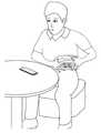
도 2는 사용자가 본 발명에 따른 심전도 측정 장치(100)를 사용하여 6 채널 모드에서 심전도를 측정하는 방법을 나타낸다. 상기 사용자는 심전도 측정 장치(100)의 한쪽 면에 구비된 전극 111과 112를 양 손으로 각각 잡고 다른 면에 구비된 전극 113을 사용자의 왼쪽 하복부(혹은 왼쪽 다리)에 접촉시킨다. 이런 방식으로 3 개의 전극을 인체에 접촉시키면 2 개의 림브 리드를 측정할 수 있으며 아래에 기술하는 바와 같이 4개의 리드를 계산하여 추가적으로 구할 수 있다. 도 2의 측정 방법은 가장 편리하게 6 채널의 심전도를 얻기 위하여 본 발명에서 제공하는 방법이다. 또한 본 발명은 도 2의 측정 방법에 가장 알맞은 장치를 제공한다. 상기 측정 방법의 원리는 다음과 같다.2 illustrates a method of measuring an electrocardiogram in a six channel mode by using an
전통적인 12-lead ECG 에 대하여는 예를 들면 [ANSI/AAMI/IEC 60601-2-25:2011, Medical electrical equipment-part 2-25: Particular requirements for the basic safety and essential performance of electrocardiographs] 에 기술되어 있다. 전통적인 12-lead ECG중에서 3개의 림브 리드 (Limb lead)는 다음과 같이 정의된다. 리드 I= LA-RA, 리드 II= LL-RA, 리드 III=LL-LA이다. 위 식들에서 RA, LA, LL은 각각 오른 손(right arm), 왼손(left arm), 왼다리(left leg) 혹은 이들 림브와 가까운 몸통 부위의 전압이다. 이때 전력선 간섭을 제거하기 위해서 종래의 기술에서는 통상적으로 오른다리(DRL) 전극을 사용한다. 상기 관계로부터 하나의 림브 리드는 다른 두 개의 림브 리드로부터 구할 수 있다. 예를 들면 리드 III= 리드 II - 리드 I 이다. 증강 림브 리드 (Augmented limb leads) 3 개는 다음과 같이 정의된다. aVR= RA-(LA+LL)/2, aVL= LA-(RA+LL)/2, aVF= LL-(RA+LA)/2. 따라서 3개의 증강 림브 리드는 2개의 limb lead로 부터 구할 수 있다. 예를 들면 aVR= -(I+II)/2 로 구할 수 있다. 따라서 두 개의 림브 리드를 측정하면 나머지 4개의 리드를 계산하여 구할 수 있다. 따라서 본 발명에서는 6개의 리드를 제공하기 위하여 3개의 전극과 두 개의 증폭기를 사용하여 두 개의 리드를 동시에 측정하기 위한 장치를 공개한다. 여기서 하나의 증폭기는 하나의 신호를 증폭한다는 의미이며 실제 구성에서는 하나의 증폭기는 직렬로 연결된(cascaded) 다수의 증폭단 혹은 능동 필터의 집합체로 구성될 수 있다. 표준적인 12-리드 심전도는 상기 6개의 리드와 V1부터 V6까지의 6개의 프리코디얼 리드(precordial leads)로 이루어진다.Traditional 12-lead ECG is described, for example, in ANSI / AAMI / IEC 60601-2-25: 2011, Medical electrical equipment-part 2-25: Particular requirements for the basic safety and essential performance of electrocardiographs. Among the traditional 12-lead ECGs, three limb leads are defined as follows. Leads I = LA-RA, leads II = LL-RA, leads III = LL-LA. In the above equations, RA, LA, and LL are the voltages of the right arm, left arm, left leg, or the trunk near these limbs, respectively. In this case, in order to remove power line interference, a conventional leg (DRL) electrode is typically used. From this relationship, one limb lead can be obtained from the other two limb leads. For example, lead III = lead II-lead I. Three augmented limb leads are defined as follows. aVR = RA- (LA + LL) / 2, aVL = LA- (RA + LL) / 2, aVF = LL- (RA + LA) / 2. Therefore, three reinforcement limb leads can be obtained from two limb leads. For example, aVR =-(I + II) / 2. Therefore, by measuring two limb leads, the remaining four leads can be calculated and calculated. Accordingly, the present invention discloses an apparatus for measuring two leads simultaneously using three electrodes and two amplifiers to provide six leads. Here, one amplifier means amplifying one signal. In an actual configuration, one amplifier may be composed of a plurality of cascaded amplifiers or a collection of active filters. A standard 12-lead electrocardiogram consists of the six leads and six prerecorded leads from V1 to V6.
MCL(Modified Chest Leads)은 상기 프리코디얼 리드와 유사하여 의학적으로 매우 유용하다. 한편 본 발명의 원리에서 3개의 전극 중에서 증폭기에 연결되지 않는 하나의 전극의 전압은 신호 주파수 대역에서 실질적으로 거의 회로공통과 같아진다. 따라서 본 발명에 의한 심전도 측정 장치(100)는 MCL1 부터 MCL6까지 6개의 MCL중에서 하나의 MCL을 측정하기에 적합하다. 각각의 MCL은 왼손이 연결되는 몸통 부위의 전압을 기준으로 해당되는 프리코디얼 리드의 위치에서의 전압이기 때문이다.Modified Chest Leads (MCL) are similar to the precordial leads and are very useful medically. On the other hand, in the principle of the present invention, the voltage of one of the three electrodes, which is not connected to the amplifier, becomes substantially equal to the circuit common in the signal frequency band. Therefore, the
도 3은 본 발명에 따른 심전도 장치를 MCL 모드로 사용하여 사용자가 MCL1을 측정하는 방법을 나타낸다. 본 발명에 따른 심전도 장치를 사용하여, 예를 들어, MCL1을 측정하기 위해서는 사용자는 도 3에서와 같이 심전도 측정 장치(100)의 한쪽 면에 구비된 전극 111과 112를 양 손으로 각각 잡고 다른 면에 구비된 전극 113을 MCL 위치(예를 들어 MCL1을 측정할 때는 V1 위치)에 접촉시키면 된다. 본 발명에서 사용자가 MCLn을 측정하기 위해서는 사용자가 상기 전극 113을 사용자 몸통의 MCLn 위치 즉 Vn 위치에 접촉시키면 된다.3 illustrates a method of measuring MCL1 by a user using an electrocardiogram device in MCL mode according to the present invention. Using the ECG device according to the present invention, for example, in order to measure the MCL1, the user grasps the
이제부터 도 4와 도 5를 이용하여 본 발명에 따른 심전도 측정 장치의 하나의 실시예에 대하여 기술한다. 도 4는 본 발명에 따른 심전도 측정 장치에서 전력선 간섭을 제거하는 원리와 실시예를 설명하는 전기적 등가회로 모델이다. 도 5는 본 발명에 따른 심전도 측정 장치에서 2 개의 싱글 엔디드 입력 증폭기를 사용하여 심전도의 2 채널을 동시에 측정하는 실시예의 전기적 등가회로 모델이다.One embodiment of an electrocardiogram measuring apparatus according to the present invention will now be described with reference to FIGS. 4 and 5. 4 is an electrical equivalent circuit model for explaining a principle and an embodiment of eliminating power line interference in an electrocardiogram measuring apparatus according to the present invention. 5 is an electrical equivalent circuit model of an embodiment in which two channels of an electrocardiogram are simultaneously measured using two single-ended input amplifiers in an electrocardiogram measuring apparatus according to the present invention.
도 4에서 전력선 간섭을 모델링하기 위하여 전류원 450을 사용하였다. 또한 도 4에서 인체를 하나의 점에서 서로 연결되는 3개의 전극 저항 (431, 432, 433)으로 모델링하였다. 또한 도 5에서는 하나의 심전도 신호를 두 개의 전극 저항 사이에 존재하는 하나의 전압원(461과 462)으로 모델링하였다. 본 발명에서는 3 개의 전극을 사용하므로 도 5에서 인체에 두 개의 심전도 전압원(461과 462)이 있는 것으로 모델링하였다. 이것은 3 개의 전극에는 3 개의 심전도 전압이 존재하지만(이것은 3 개의 전극 중에서 두 개의 전극을 선택하는 경우의 수가 3이기 때문이다.) 두 개의 심전도 전압 만이 독립적이기 때문이다. 상기 도 4의 전력선 간섭에 대한 모델링과 도 5의 심전도 신호에 대한 모델링은 간략화된 것이다. 그러나 상기 모델들은 풀어야 할 문제를 명확히 하기 위하여 적합하다. 또한 상기 모델들은 본 발명에서 무엇을 고안해야 할지를 명확히 제시한다. 또한 상기 모델들을 사용하면 본 발명을 쉽게 이해할 수 있다. 본 발명은 상기 모델들을 기반으로 고안되었다. 종래의 기술들은 상기와 같은 모델들을 사용하지 않았기 때문에 종래의 기술들은 문제의 해결 방법을 정확하게 제시할 수 없었다.In FIG. 4, a
본 발명은 이후 설명하는 바와 같이 여러가지 실시예로 표현될 수 있다. 그러나 본 발명의 여러가지 실시예는 공통적으로 다음과 같은 본 발명의 원리를 기반으로 한다. 본 발명의 원리는 본 발명을 위하여 본 발명에서 고안된 것이다. 본 발명의 원리는 종래의 기술에서 사용되었던 DRL에 비하여 DRL 전극을 사용하지 않는다는 차이점이 있다.The invention can be expressed in various embodiments as described below. However, various embodiments of the present invention are commonly based on the following principles of the present invention. The principles of the present invention are devised in the present invention for the present invention. The principle of the present invention is that it does not use a DRL electrode compared to the DRL used in the prior art.
DRL 전극을 사용하지 않는 종래의 심전도 측정 장치에서 해결하지 못하였으며 필수적으로 해결이 요구되는 문제는 전력선 간섭을 제거 혹은 감소시키는 것이다. 심전도 측정 장치에서의 전력선 간섭은 도 4에서와 같이 출력 임피던스가 상당히 커서 실질적으로 무한대인 출력 임피던스를 갖는 전류원에 의하여 발생한다. (도 4에서 전력선 간섭 전류원은 450으로 나타내었다.) 따라서 전력선 간섭을 제거하기 위해서는 상기 전력선 간섭 전류원에서 인체를 들여다 보는 임피던스를 최소화할 것이 요구된다. 상기 전력선 간섭 전류원에서 인체를 들여다 보는 임피던스는 인체 자체의 임피던스와 심전도 측정 장치의 임피던스의 합이다. 결국 3개의 전극을 통하여 들여다 보는 심전도 측정 장치의 임피던스를 최소화 할 것이 요구된다. 한편 심전도를 측정하기 위하여 사용하는 전극과 인체 사이에는 소위 전극 임피던스 혹은 전극 저항(도 4에서 431, 432, 433)라고 하는 임피던스가 존재한다. 따라서 전극 임피던스에 의한 영향을 최소화하고 심전도 전압을 측정하기 위해서는 심전도 측정 장치는 높은 임피던스를 갖어야 한다. 따라서 심전도 측정 장치는 전력선 간섭을 제거하기 위해서는 낮은 임피던스를 가져야 하며 심전도 전압을 측정하기 위해서는 높은 임피던스를 가져야 하는 두 개의 서로 상반되는 조건을 만족시켜야 한다.The problem that has not been solved in the conventional electrocardiogram measuring apparatus which does not use the DRL electrode and which needs to be solved is to eliminate or reduce power line interference. Power line interference in the electrocardiogram measuring device is caused by a current source having an output impedance that is substantially infinite because the output impedance is considerably large as shown in FIG. 4. (In Fig. 4, the power line interference current source is shown as 450.) Therefore, in order to eliminate the power line interference, it is required to minimize the impedance that looks into the human body from the power line interference current source. The impedance seen by the human body from the power line interference current source is the sum of the impedance of the human body itself and the impedance of the ECG measuring device. As a result, it is required to minimize the impedance of the electrocardiograph, which is viewed through three electrodes. On the other hand, between the electrode used to measure the electrocardiogram and the human body, an impedance called so-called electrode impedance or electrode resistance (431, 432, 433 in FIG. 4) exists. Therefore, in order to minimize the influence of the electrode impedance and measure the ECG voltage, the ECG measuring apparatus should have a high impedance. Therefore, the ECG measuring apparatus must satisfy two mutually opposing conditions that must have a low impedance to remove power line interference and must have a high impedance to measure the ECG voltage.
상기 두 개의 서로 상반되는 조건을 만족시키기 위해서 가능하다고 생각할 수 있는 방법은 예를 들어 3개의 전극을 사용하는 경우 3개의 전극에 값이 큰 저항 3개를 각각 연결하고 상기 3개의 저항의 다른 쪽 끝을 하나의 점으로 함께 묶으며 3개의 전극의 공통모드 신호를 저항 3개가 묶인 상기 하나의 점으로 네가티브 피드백하는 것이다. 그러나 이 방법은 실질적으로 사용하기에 어렵다. 왜냐하면 전력선 간섭 전류원의 임피던스가 커서 전력선 간섭 전류의 크기가 줄어들지 않기 때문이다. 따라서 이 경우에 상기 3 개의 저항에 유도되는 전력선 간섭 전압은 여전히 상당히 크다. 혹은 증폭기가 포화될 수 있다. 또한 전력선 간섭 전류의 크기가 줄어들지 않았으며 각각의 전극 임피던스는 서로 다를 수 있기 때문에 각각의 전극에는 서로 다른 전력선 간섭 전압이 상당히 높게 유도된다. 그러므로 설사 차동증폭기를 사용하여도 각각의 전극에 유도된 전력선 간섭을 제거하기 어렵다. 이것이 종래 기술의 어려움이었다.A method that can be considered as possible in order to satisfy the two mutually opposing conditions is, for example, when using three electrodes, connecting three large resistors to each of the three electrodes and the other end of the three resistors. Are bundled together into a single point, and the common mode signal of the three electrodes is negatively fed back to the single point where the three resistors are tied together. However, this method is practically difficult to use. This is because the impedance of the power line interference current source is large so that the magnitude of the power line interference current does not decrease. Thus in this case the power line interference voltage induced by the three resistors is still quite large. Alternatively, the amplifier may be saturated. In addition, since the magnitude of the power line interference current has not been reduced and each electrode impedance may be different, different power line interference voltages are induced at each electrode significantly higher. Therefore, even with a differential amplifier, it is difficult to eliminate power line interference induced at each electrode. This was a difficulty of the prior art.
따라서 본 발명에서는 심전도 측정 장치에 설치된 전극들 중에서 하나의 전극으로만 전력선 간섭 전류가 집중되어 흐르도록 한다. 이렇게 하기 위하여 3개의 전극이 인체에 연결된 상태에서 전력선 간섭 전류원이 상기 하나의 전극을 통하여 심전도 측정 장치를 들여다 보는 임피던스를 최소화한다. 그러면 전력선 간섭 전류원에 의하여 인체에 유도되는 전력선 간섭 전압(도 4에서는 440 로 표시함)이 최소화된다. 그러면 인체에 유도되는 전력선 간섭 전압이 최소화되었으므로 심전도 측정 장치의 다른 전극의 입력 임피던스를 크게 할 수 있으며 심전도 전압을 정확하게 측정할 수 있다. 이때 중요한 점은 전력선 간섭 전류가 집중되어 흐르는 상기 하나의 전극에는 전력선 간섭 전압이 높게 유도되므로 상기 하나의 전극은 측정에 사용되지 말아야 한다는 점이다. 그러므로 본 발명에서는 3개의 전극을 사용하는 경우 2 개의 전극과 상기 2 개의 전극으로부터 심전도 신호를 받는 2 개의 증폭기를 측정에 사용한다는 특징을 갖는다. 특히 주목하여야 할 점은 3 개의 전극을 사용하는 심전도 측정 장치에서 2 개의 전극만을 측정에 사용하여야 하므로 2 개의 차동증폭기를 사용할 수 없다는 점이다. 또한 주의할 점은 네가티브 피드백을 사용하는 경우 모든 주파수 대역에서 네가티브 피드백이 이루어지면 심전도 신호가 피드백되는 전극 쪽에 발생하여 전력선 간섭 전압과 혼합되므로 전력선 간섭 주파수에서만 네가티브 피드백이 이루어져야 한다는 점이다. 이하 본 발명에 대한 상세한 설명을 도면을 사용하여 기술한다.Therefore, in the present invention, the power line interference current flows only to one electrode among the electrodes installed in the ECG apparatus. In order to do this, the power line interference current source minimizes the impedance of the electrocardiogram measuring device through the one electrode while the three electrodes are connected to the human body. This minimizes the power line interference voltage (indicated by 440 in FIG. 4) induced in the human body by the power line interference current source. Then, since the power line interference voltage induced to the human body is minimized, the input impedance of the other electrode of the ECG apparatus can be increased, and the ECG voltage can be accurately measured. The important point here is that the power line interference voltage is induced to the one electrode through which the power line interference current is concentrated, so that the one electrode should not be used for the measurement. Therefore, in the present invention, when three electrodes are used, two electrodes and two amplifiers receiving ECG signals from the two electrodes are used for the measurement. It should be noted that in the electrocardiogram measuring apparatus using three electrodes, only two electrodes should be used for the measurement, so two differential amplifiers cannot be used. In addition, when negative feedback is used in all frequency bands, negative feedback should be performed only at the power line interference frequency because the ECG signal is generated on the electrode side fed back and mixed with the power line interference voltage. DETAILED DESCRIPTION Hereinafter, a detailed description of the present invention will be described with reference to the drawings.
도 4 및 이후의 도면에서 본 발명에 의한 심전도 측정장치 100은 편의상 본 발명에 의한 장치의 일부만을 나타내고 있다. 도 4에서 본 발명에 의한 심전도 측정장치 100은 3 개의 전극 111, 112, 113과 2 개의 증폭기 411과 412를 포함한다. 도 5에서 본 발명에서 사용하는 상기 2 개의 증폭기 411과 412는 차동증폭기가 아니고 싱글 엔디드 입력 증폭기인 특징이 있다.4 and the subsequent figures, the
본 발명의 도 4에 나타낸 실시예의 중요한 특징은 본 발명에 의한 심전도 측정 장치 100이 대역통과필터 413을 포함하는 것이다. 상기 대역통과필터 413의 입력은 하나의 전극 112에 연결된다. 상기 대역통과필터 413의 출력은 저항 423을 통하여 전극 113으로 피드백 된다. 상기 대역통과필터 413의 공진주파수 즉 피크주파수는 전력선 간섭의 주파수와 동일하다. 또한 상기 대역통과필터 413은
본 발명에서 3개의 전극 중에서 2개는 값이
도 4에서 430은 인체의 모델이다. 인체와 전극 사이에는 통상 전극 임피던스로 불리우는 접촉 저항이 존재한다. 도 4에서 인체 430과 3 개의 전극 111, 112, 113 사이에 존재하는 전극 임피던스(전극 저항)를 각각 저항 431, 432, 433으로 나타내었다. 전극 저항 431, 432, 433의 소자값은 각각
도 4에서 450은 전력선 간섭 모델링에서 통상적으로 사용되는 전력선 간섭 전류원이다. 전력선 간섭 전류원 450의 전류


회로해석을 위하여 인체 430에 유도되는 전력선 간섭을


상기 식 4는 저항 423의 저항값으로

위에서

본 발명에서 다음의 근사(식 7과 식 8)가 가능하도록 도 4의 회로의 소자값을 사용한다. 식 7과 식 8은 본 발명의 중요한 요소이다.In the present invention, the element values of the circuit of Fig. 4 are used to enable the following approximations (Equations 7 and 8). Equations 7 and 8 are important elements of the present invention.


그러면 다음의 근사가 성립한다.Then the following approximation holds.

위 식 9로부터 다음을 얻는다.From equation 9 we get

식 10에서 피드백이 없으면 즉 만일

식 10과 식 11을 비교하여 우리는 본 발명의 효과로 전력선 간섭 전류


식 2와 식 10을 사용하여 다음을 확인할 수 있다.

이제


식 12와 식 13으로부터 다음을 알 수 있다.From

이것은 피드백의 결과로
이제부터 본 발명에 의하여 3 개의 전극을 사용하여 2 개의 심전도 채널 신호들을 얻는 원리를 기술한다. 도 5는 본 발명에 의한 심전도 장치를 이용하여 심전도를 측정할 때의 등가회로이다. 도 5에서


상기 식 15에서 기호


그러므로 상기 식7과 식 8의 조건에서 전압

위 식으로부터 신호 대역에서

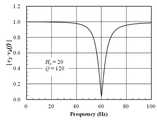
도 6은 본 발명에 따른 심전도 측정 장치에서 사용되는 대역통과필터의 주파수 응답을 보여준다. 도 6에서 대역통과필터의 공진 주파수에서의 이득은 20이고

마찬가지로 전극 1의 전압


식 7과 식 8의 조건을 사용하면 전압

위 식은 식 16을 사용하여 구하였다. 위 식으로부터 다음의 식 20을 얻고 이 식에 의하여


이로써 본 발명에 의하여 두 개의 싱글 엔디드 증폭기를 사용하여 두 개의 심전도 채널의 신호들을 얻는 원리를 기술하였다.Thus, the present invention describes the principle of obtaining signals of two ECG channels using two single-ended amplifiers.
도 8은 본 발명에 따른 심전도 측정 장치에서 두개 전극의 공통모드 신호를 사용하여 전력선 간섭을 제거하는 원리와 실시예를 설명하는 전기적 등가회로 모델이다. 당연히 공통모드 신호를 사용하여도 전력선 간섭 전류는 피드백되는 전극을 통하여 집중되어 흐르며 상기 전극에는 전력선 간섭 전압이 높게 존재하게 된다. 도 9는 도 8의 방법으로 즉 공통모드 신호를 사용하여 전력선 간섭을 제거할 때 하나의 차동증폭기와 하나의 싱글 엔디드 입력 증폭기를 사용하여 심전도의 2 채널을 동시에 측정하는 실시예의 전기적 등가회로 모델이다. 앞에서 두개의 싱글 엔디드 입력 증폭기를 사용할 때 처럼 두개의 심전도 전압을 구할 수 있다. 대역통과필터의 피크값이 큰 경우 신호대역에서

도 10은 도 8에 비하여 대역통과필터를 사용하지는 않고 하나의 전극을 작은 저항값
본 발명에 따른 심전도 측정 장치는 가장 적은 수의 전극 (구체적으로는 3 개의 전극)을 사용하여 동시에 얻은 6 개의 심전도 리드를 제공한다. 본 발명에 따른 심전도 측정 장치를 MCL 모드에서 사용하면 하나의 림브 리드와 하나의 MCL을 측정할 수 있다.The electrocardiogram measuring device according to the invention provides six electrocardiogram leads obtained simultaneously using the fewest number of electrodes (specifically three electrodes). When the ECG measuring apparatus according to the present invention is used in the MCL mode, one limb lead and one MCL may be measured.
본 발명에 따른 휴대용 심전도 측정 장치는 하나의 신용카드 형태의 장치로 휴대하기에 편리하여 시간과 장소에 구애 받지 않고 가장 편리하게 복수의 심전도를 얻을 수 있고, 무선으로 스마트폰과 통신하므로 본 발명에 의한 심전도 측정 장치와 스마트폰 사이의 거리에 실질적인 제한없이 편리하게 사용할 수 있다.The portable ECG measuring device according to the present invention is convenient to carry with one credit card type device, so that it is possible to obtain a plurality of ECGs most conveniently regardless of time and place, and wirelessly communicates with a smartphone. Can be conveniently used without a practical limitation on the distance between the ECG device and the smart phone.
또한, 본 발명에 따른 상기 심전도 측정 장치는 사용하지 않을 때는 전류감지기를 제외한 모든 회로가 power off 되고 마이크로콘트롤러만 슬립 모드(sleep mode)에 들어가도록 하며, 사용할 때는 필요한 회로에만 전력을 공급하고 상기 마이크로콘트롤러는 활성화 모드로 들어가도록 하므로 심전도 측정 장치에 내장된 배터리의 전력소모를 최대로 감소시킬 수 있다.In addition, the ECG measuring apparatus according to the present invention, when not in use, all circuits except the current sensor is powered off and only the microcontroller to enter a sleep mode (power mode), when used to supply only the necessary circuitry and The controller allows the controller to enter active mode, maximizing power consumption of the battery built into the ECG.
또한, 본 발명에 의한 상기 심전도 측정 장치는 기계적인 전원 스위치나 선택 스위치를 포함하지 않도록 하여 소형, 박형화를 가능하게 하며, 사용자가 스위치를 사용하는 불필요한 번거로움, 스위치의 고장 가능성과 유한한 수명, 제조 가격의 상승을 초래하지 않는다.In addition, the electrocardiogram measuring apparatus according to the present invention does not include a mechanical power switch or a selection switch to enable a compact and thin, and the user is unnecessary to use the switch, the possibility of failure of the switch and a finite lifetime, It does not cause a rise in manufacturing price.
또한, 본 발명에 의한 상기 심전도 측정 장치 장치는 LCD 등의 디스플레이를 포함하지 않으므로 디스플레이의 고장 가능성과 열화, 제조 가격의 상승을 초래하지 않으며 소형이어서 휴대하기 편리하다.In addition, the electrocardiogram measuring apparatus according to the present invention does not include a display such as an LCD, and thus does not cause a possibility of failure of the display, deterioration, and an increase in manufacturing price, and is compact and convenient to carry.
도 1은 본 발명에 따른 3개의 전극을 구비한 심전도 측정 장치의 사시도.
도 2는 본 발명에 따른 심전도 측정 장치를 사용하여 6 채널 모드에서 심전도를 측정하는 방법.
도 3은 본 발명에 따른 심전도 측정 장치를 사용하여 MCL 모드에서 심전도를 측정하는 방법.
도 4는 본 발명에 따른 심전도 측정 장치에서 전력선 간섭을 제거하는 원리와 실시예를 설명하는 전기적 등가회로 모델.
도 5는 본 발명에 따른 심전도 측정 장치에서 2 개의 싱글 엔디드 입력 증폭기를 사용하여 심전도의 2 채널을 동시에 측정하는 실시예의 전기적 등가회로 모델.
도 6은 본 발명에 따른 심전도 측정 장치에서 사용되는 대역통과필터의 주파수 응답.
도 7은 본 발명에 따른 심전도 측정 장치에서 하나의 신호 채널의 주파수 응답.
도 8는 본 발명에 따른 심전도 측정 장치에서 공통모드 신호를 사용하여 전력선 간섭을 제거하는 원리와실시예를 설명하는 전기적 등가회로 모델.
도 9는 본 발명에 따른 심전도 측정 장치에서 공통모드 신호를 사용하여 전력선 간섭을 제거할 때 하나의 차동증폭기와 하나의 싱글 엔디드 입력 증폭기를 사용하여 심전도의 2 채널을 동시에 측정하는 실시예의 전기적 등가회로 모델.
도 10은 본 발명에 따른 심전도 측정 장치에서 하나의 차동증폭기와 하나의 싱글 엔디드 입력 증폭기를 사용하여 심전도의 2 채널을 동시에 측정하는 다른 실시예
도 11은 본 발명에 따른 심전도 측정 장치에 내장된 회로의 블록도.
도 12는 본 발명에 따른 심전도 측정 장치의 동작 흐름도.
도 13은 본 발명에 따른 심전도 측정 장치를 사용하기 위하여 스마트폰 앱을 실행시켰을 때 스마트폰의 초기 화면
도 14는 본 발명에 따른 심전도 측정 장치를 사용할 때의 스마트폰 앱의 흐름도.
도 15는 혈액 시험 스트립 삽입구가 구비된 본 발명에 따른 심전도 측정 장치
도 16은 본 발명에 따른 4개의 전극을 구비한 심전도 측정 장치의 사시도.1 is a perspective view of an electrocardiogram measuring apparatus having three electrodes according to the present invention.
2 is a method for measuring an electrocardiogram in a six-channel mode using the electrocardiogram measuring device according to the present invention.
Figure 3 is a method for measuring the electrocardiogram in MCL mode using the electrocardiogram measuring device according to the invention.
Figure 4 is an electrical equivalent circuit model for explaining the principle and embodiment for removing power line interference in the electrocardiogram measuring apparatus according to the present invention.
5 is an electrical equivalent circuit model of an embodiment in which two channels of an electrocardiogram are simultaneously measured using two single-ended input amplifiers in an electrocardiogram measuring apparatus according to the present invention.
Figure 6 is a frequency response of the bandpass filter used in the electrocardiogram measuring apparatus according to the present invention.
7 is a frequency response of one signal channel in the electrocardiogram measuring device according to the present invention.
8 is an electrical equivalent circuit model illustrating a principle and an embodiment of eliminating power line interference using a common mode signal in an electrocardiogram measuring apparatus according to the present invention.
9 is an electrical equivalent circuit of an embodiment in which two channels of an electrocardiogram are simultaneously measured using one differential amplifier and one single-ended input amplifier when removing power line interference using a common mode signal in an electrocardiogram measuring apparatus according to the present invention. Model.
10 is another embodiment in which two channels of an ECG are simultaneously measured using one differential amplifier and one single-ended input amplifier in an ECG measuring apparatus according to the present invention.
11 is a block diagram of a circuit embedded in an electrocardiogram measuring device according to the present invention.
12 is an operation flowchart of an electrocardiogram measuring apparatus according to the present invention.
Figure 13 is the initial screen of the smartphone when running the smart phone app to use the electrocardiogram measuring device according to the invention
14 is a flowchart of a smartphone app when using the ECG measuring device according to the present invention.
15 is an electrocardiogram measuring device according to the present invention provided with a blood test strip insertion hole
16 is a perspective view of an electrocardiogram measuring device with four electrodes according to the present invention.
이하, 도면을 참고하여 본 발명에 따른 실시예를 설명한다. 본 실시예에서 심전도(ECG) 측정 장치는 3 개의 전극을 포함하는 것으로 예를 들어 설명하나, 이에 국한되지는 않고 상기 심전도 측정 장치는 3 개 이상의 전극을 포함한 장치일 수 있다. 본 발명에 대한 중요한 실시예는 본 발명의 원리를 설명하기 위하여 앞에서 이미 도 4부터 도 10까지 사용하여 기술하였다.Hereinafter, with reference to the drawings will be described an embodiment according to the present invention. In the present embodiment, an ECG measuring apparatus includes three electrodes, for example, but is not limited thereto. The ECG measuring apparatus may be a device including three or more electrodes. An important embodiment of the present invention has been described previously using FIGS. 4 to 10 to illustrate the principles of the present invention.
본 발명에 따른 휴대용 심전도 측정 장치는 휴대성을 높이기 위하여 신용카드 형태이고 두께는 6 mm 이하가 바람직하다. 본 발명에 따른 휴대용 심전도 측정 장치는 휴대용이므로 배터리를 사용하며 CR2032형 배터리를 사용하는 경우 2년 정도의 사용시간이 가능하다.Portable ECG measuring apparatus according to the present invention is in the form of a credit card in order to increase portability, the thickness is preferably 6 mm or less. Since the portable ECG measuring apparatus according to the present invention is portable, a battery is used and a use time of about 2 years is possible when using a CR2032 type battery.
또한, 휴대용 심전도 측정 장치의 소형화를 위하여 기계적 전원 스위치나 선택 스위치가 없고, 전력소모를 감소시키기 위하여 디스플레이를 사용하지 않는다.In addition, there is no mechanical power switch or selection switch for miniaturization of the portable ECG device, and no display is used to reduce power consumption.
본 발명에 의한 휴대용 심전도 측정 장치에서는 기계적 전원 스위치나 선택 스위치를 사용하지 않기 위하여 전류감지기를 사용할 수 있다. 상기 전류감지기는 동작에 필요한 전력을 항상 공급받으며 이벤트가 발생하면 출력신호를 발생시키기 위해 대기한다. 사용자가 심전도를 측정하기 위하여 복수의 전극들을 인체에 접촉시키면 전류가 흐를 수 있는 루프가 생성된다. 따라서 상기 인체가 상기 전류감지기와 전기적으로 연결되면 상기 전류감지기가 상기 인체에 미세 전류가 흐르도록 하며, 상기 전류감지기는 상기 미세 전류를 감지하여 출력신호를 발생시킨다. 배터리의 사용시간을 증가시키기 위해서 휴대용 심전도 측정 장치를 사용하지 않을 경우에는 상기 전류감지기만 동작하고 나머지 회로들은 power off 되며 마이크로콘트롤러는 슬립(sleep) 모드로 대기한다. 이때 양쪽 손을 2개의 전극들에 터치하는 이벤트가 발생하여 전류 감지기가 출력신호를 발생하면 상기 마이크로콘트롤러는 활성화되어 심전도 회로를 power on 시킨다. 상기 전류감지기가 감지하는 상기 전류는 상기 휴대용 심전도 측정 장치에 구비된 배터리로부터 공급되며 직류 전류인 것을 특징으로 한다.In the portable electrocardiogram measuring apparatus according to the present invention, a current sensor may be used in order not to use a mechanical power switch or a selection switch. The current sensor is always supplied with the power required for operation and waits to generate an output signal when an event occurs. When a user contacts a plurality of electrodes with a human body to measure an electrocardiogram, a loop in which current may flow is generated. Therefore, when the human body is electrically connected to the current sensor, the current sensor allows the micro current to flow through the human body, and the current sensor senses the micro current to generate an output signal. When the portable ECG is not used to increase the battery life, only the current sensor operates, the remaining circuits are powered off, and the microcontroller waits in the sleep mode. At this time, when an event occurs in which both hands touch the two electrodes and the current sensor generates an output signal, the microcontroller is activated to power on the ECG circuit. The current sensed by the current sensor is supplied from a battery provided in the portable ECG device, characterized in that the direct current.
본 발명에 의한 심전도 측정 장치(100)는 혈당 레벨, 케톤(Ketone) 레벨, 혹은 INR(International Normalized Ratio) 등 혈액 특성을 측정하는 기능을 추가하여 포함할 수 있다. 그러므로 본 실시예에서 심전도 측정 장치(100)는 심전도와 혈액 특성을 함께 측정하기 위한 예를 들어 설명한다. 상기의 혈당레벨이나 케톤 레벨은 암페로메트릭 (amperometric) 방법을 사용하여 측정 할 수 있다. 상기의 INR은 혈액응고 경향을 나타내는 척도로서 모세혈에 대한 전기 임피던스 방법, 암페로메트릭 방법, 기계적 방법 등을 사용하여 측정 할 수 있다. 상기 혈액 특성 시험에 필요한 혈액 시험 스트립을 삽입할 수 있는 하나의 혈액 시험 스트립 삽입구는 본 발명에 따른 심전도 측정 장치의 케이스에 구비할 수 있다.The
본 발명에 따른 심전도 측정 장치(100)의 실시예에서는 체온계 기능을 포함할 수 있다. 본 발명에 따른 심전도 측정 장치(100)에 체온계 기능을 포함시키기 위하여 적합한 형태는 접촉식이며 적합한 온도 센서는 써미스터(thermistor)이다. 체온계 기능이 포함된 본 발명에 따른 심전도 측정 장치(100)를 사용하여 체온을 측정하기 위해서는 온도 센서가 부착된 심전도 측정 장치(100)의 부위를 사용자가 사용자의 이마 혹은 겨드랑이에 접촉시킨다. 정확한 체온 측정을 위하여는 상기 온도 센서가 부착된 상기 심전도 측정 장치(100)의 상기 부위에 의하여 피부의 온도가 변화되지 않도록 하여야 한다.In the embodiment of the
도 11은 본 발명에 따른 심전도 측정 장치(100)에 내장된 회로의 블록도를 나타낸다. 본 발명을명확히 하기 위하여 도 11에는 모든 블록을 표시하지는 않았으나 본 발명에 의한 심전도 측정 장치는 전류감지기와 혈액 시험 회로 및 혈액 시험 스트립 삽입구 등을 포함할 수 있다. 도 11의 각 블록의 기능과 동작은 다음과 같다. 사용자가 한 쌍의 전극(111, 112)을 양쪽 손으로 터치하였을 때 심전도 전류감지기는 상기 양쪽 손을 통하여 미세한 전류가 흐르도록 하며 상기 양쪽 손을 통하여 흐르는 상기 미세한 전류를 검출한다. 그러면 상기 전류감지기는 상기 마이크로콘트롤러(1180)를 슬립 모드에서 활성화 모드로 변경되도록 신호를 발생한다. 그러면 상기 마이크로콘트롤러(1180)는 상기 심전도 측정회로(1160)와 상기 AD변환기(1170)를 power on시킨다. 상기 심전도 측정회로(1160)는 2개의 심전도 신호를 2개의 증폭기에서 증폭하여 2개의 출력을 발생한다. 상기 AD변환기(1170)는 상기 심전도 측정회로(1160)의 2 개의 출력을 받으며 상기 AD변환기(1170)의 출력들은 상기 무선통신 수단(1190)과 안테나(1192)을 통하여 상기 스마트폰(210)으로 송신된다. 데이터를 수신한 상기 스마트폰(210)은 복수의 심전도 파형을 디스플레이한다. 일정한 시간 동안의 측정이 끝나면 상기 마이크로콘트롤러(1180)는 슬립 모드로 들어가서 다음번 양쪽 손의 터치를 기다린다. 도 11에 표시된 블록의 각각은 상용화된 부품을 사용하여 종래의 기술로 구현이 가능하다.11 is a block diagram of a circuit embedded in the
도 12는 심전도를 측정할 때의 본 발명에 의한 상기 심전도 측정 장치(100)의 동작 흐름도이다. 사용자가 심전도를 측정하기 위해서 상기 심전도 측정 장치(100)의 상기 한 쌍의 전극(111, 112)을 각각 양쪽 손으로 접촉한다(1210). 그러면 양쪽 손 사이에 인체를 통하여 흐르는 미세 전류를 감지한 상기 전류감지기가 출력신호를 발생시킨다(1215) 이 출력신호는 상기 마이크로콘트롤러(1180)의 인터럽트를 발생시켜 상기 마이크로콘트롤러(1180)를 활성화시킨다(1220). 활성화된 상기 마이크로콘트롤러(1180)는 상기 무선통신 수단(1190)을 활성화시킨다. 지금부터 상기 무선통신 수단(1190)이 블루투스 로우 에너지 장치인 경우에 대하여 기술한다. 상기 심전도 측정 장치(100)의 상기 무선통신 수단(1190)이 블루투스 로우 에너지 주변장치(peripheral)로서 광고(advertizing)한다(1225). 이때 블루투스 로우 에너지 중앙장치(central)로서 스캐닝(scanning)하고 있던 스마트폰이 상기 심전도 측정 장치(100)를 발견하여 연결을 시도한다. 이때 상기 심전도 측정 장치(100)가 연결을 승인하면 상기 스마트폰과 상기 심전도 측정 장치(100)는 블루투스 로우 에너지 연결 상태(connected)가 된다(1230). 이때 상기 심전도 측정 장치(100)는 사용자가 실제로 심전도 측정을 하기 위하여 사용자가 스마트폰의 심전도 측정 버튼을 터치하였는지 확인할 수 있다(1235).12 is an operation flowchart of the
이제 심전도 측정을 요구 받은 것을 확인하였으면 상기 마이크로콘트롤러(1180)는 상기 심전도 측정회로(1160)를 power on 시킨다(1240). 이것은 심전도 측정회로(1160)에 상기 마이크로콘트롤러(1180)의 출력 핀을 연결하고 상기 출력핀의 전압을 High로 하여 수행할 수 있다. 다음으로 상기 한 쌍의 전극(111, 112)이 양쪽 손에 터치되고 있는 상태인지를 상기 전류감지기를 이용하여 확인한다(1245). 이 단계는 상기 마이크로콘트롤러(1180)가 심전도 측정을 언제부터 시작할지 즉, AD변환을 언제부터 시작할지를 결정하기 위한 것이다. 즉 상기 전극들(111, 112)에 양쪽 손이 계속적으로 접촉되어 있는지를 확인하기 위한 것이다.When it is confirmed that the electrocardiogram measurement has been requested, the
상기의 과정 후에 상기 마이크로콘트롤러(1180)는 심전도 측정을 시작한다(1250). 즉 상기 마이크로콘트롤러(1180)는 미리 설정된 AD변환 주기에 맞추어서 AD변환을 수행하고 AD변환 결과를 가져온다. 본 발명에서는 두 개의 심전도 신호를 측정한다. 측정된 심전도 데이터는 상기 스마트폰(210)으로 송신되고(1255) 미리 설정된 측정 시간, 예를 들면 30초가 경과하면 상기 마이크로콘트롤러(1180)는 슬립모드로 된다(1260).After the above process, the
도 11의 모든 회로는 상기 심전도 측정 장치(100)에 내장된 배터리에 의하여 구동된다. 도 11에는 어떠한 기계적 전원 스위치, 기계적 선택 스위치, 디스플레이가 없을 수 있다. 도 11에서 상기 심전도 측정 장치(100)가 측정을 하지 않을 때는 상기 심전도 전류감지기와 상기 마이크로콘트롤러(1180)는 각각 대략 1 uA를 소모하며 다른 모든 블록은 완전히 power off 된다.All circuits of FIG. 11 are driven by a battery built in the
본 발명에 의한 심전도 측정 장치(100)는 스마트폰(210)과 함께 사용된다. 도 13은 본 발명에 따른 스마트폰 앱을 실행시켰을 때 스마트폰의 초기 화면을 보여준다. 스마트폰 앱이 실행되면 스마트폰(210)의 디스플레이(1320)에 터치 버튼들(1331, 1332, 1334, 1336, 1342, 1344, 1346, 1350)을 보여준다. 심전도와 관련된 버튼들(1331, 1332, 1334, 1336)은 심전도 박스(1330) 내에 구성된다. 본 발명에 의한 심전도 측정 장치(100)가 혈액 특성을 측정하는 기능을 포함하는 경우에는 혈액 특성과 관련된 버튼(1342, 1344, 1346)이 혈당 박스(1340) 내에 구성된다. 사용자가 심전도를 측정하기 위해서는 측정하고자 하는 심전도 측정 모드 버튼(1331, 1332)의 하나를 선택하여 터치한다. 사용자가 6-채널 모드에서 심전도를 측정할 때는 버튼 1331을 터치한다. 사용자가 MCL 모드에서 심전도를 측정할 때는 버튼 1332을 터치한다. 그런 후 사용자가 상기 심전도 측정 장치(100의 상기 한 쌍의 전극(111과 112)을 각각 양쪽 손으로 터치하고 있으면 위에서 기술한 바와 같이 상기 심전도 측정 장치(100)가 심전도를 측정한다. 측정된 심전도 데이터는 상기 스마트폰 디스플레이(1320)에 차트 형태로 나타나고 상기 스마트폰(210)에 저장된다. 과거에 저장된 심전도 측정 데이터를 다시 차트 형태로 보려면 열기 버튼(1334)을 터치한다. 의사나 병원으로 저장된 데이터를 보내려면 전송 버튼(1336)을 터치한다. 설정 버튼(1350)은 사용자의 이름, 생년월일, 성별, 주소 등을 기록하거나 선택사항들을 설정하고자 할 때 터치한다.The
도 14는 본 발명에 따른 스마트폰 앱의 흐름도를 나타내었다. 편의상 심전도를 측정하는 과정에 대하여만 기술한다. 도 14에 보인 것과 같이 심전도를 측정할 때의 흐름은 중심 줄기(1422, 1424, 1426, 1428, 1430, 1432)와 블루투스 로우 에너지(BLE) 줄기(1452, 1454)의 두 개의 줄기로 구성된다. 앱이 시작되면 스마트폰 디스플레이(1320)에 각종 버튼들이 나타난(1410) 후 블루투스 로우 에너지 통신 수행을 위한 상기 BLE 줄기(1452, 1454)가 시작된다. 심전도를 측정하고자 하는 사용자는 상기 심전도 측정 버튼들(1331과 1332)의 하나를 터치한다(1422).14 is a flowchart of a smartphone app according to the present invention. For convenience, only the procedure for measuring ECG is described. As shown in FIG. 14, the flow when measuring an electrocardiogram is composed of two stems, a
사용자가 상기 심전도 측정 버튼들(1331 혹은 1332)의 하나를 터치(1422)하면 심전도 측정 요구 신호가 상기 BLE 줄기(1452, 1454)로 보내진다(1424). 또한 상기 스마트폰 디스플레이(1320)에는 상기 심전도 측정 모드에 맞추어서 전극들을 접촉하라는 메시지가 표시된다(1424). 상기 BLE 줄기(1452, 1454)에서는 상기 심전도 측정 장치(100)로 심전도 측정 요구 신호를 보낸다(1454).When the user touches 1422 one of the
심전도 측정 요구 신호를 받은 상기 심전도 측정 장치(100)에서는 도 12에서 기술한 심전도 측정 임무를 수행하여 다시 상기 BLE 줄기(1452, 1454)로 측정된 심전도 데이터를 전송한다. 상기 BLE 줄기(1452, 1454)는 상기 심전도 측정 장치(100)로 부터 수신한 상기 심전도 데이터를 상기 중심 줄기(1422, 1424, 1426, 1428, 1430, 1432)로 전달한다. 이제 상기 중심 줄기(1422, 1424, 1426, 1428, 1430, 1432)가 상기 심전도 데이터를 수신한다(1426). 수신한 상기 심전도 데이터를 상기 중심 줄기(1422, 1424, 1426, 1428, 1430, 1432)에서 상기 스마트폰 디스플레이(1320)에 차트 형태로 디스플레이 한다(1428). 모든 심전도 측정이 끝나면 측정된 심전도 데이터를 화일 형태로 스마트폰 저장장치에 저장한다(1430). 측정된 심전도 데이터가 상기 스마트폰 디스플레이(1320)에 차트 형태로 디스플레이 되고 있는 상태에서 스마트폰 앱은 사용자가 앱 종료 버튼을 눌러서 앱을 끝내기를 기다린다(1432).The
본 발명에 의하면 사용자가 아무런 기계적 스위치나 선택 스위치, 디스플레이를 구비하지 않은 심전도 측정 장치(100)와 사용법이 간소화된 스마트폰 앱을 사용하여 가능한 모든 작동 순서의 경우의 수에 대하여 이상 없이 원하는 결과를 제공받을 수 있다.According to the present invention, the user can use the
이상과 같이 하나의 휴대용 심전도 측정 장치(100)와 스마트폰 앱을 사용하여 심전도를 측정하고자 하는 경우에 대해서 본 발명을 구체적으로 설명하였으나, 본 발명에 의한 심전도 측정 장치(100)는 이에 한정되지 않고 여러 가지 측정항목을 추가로 측정할 수 있다.As described above, the present invention has been described in detail with reference to a case in which a single
앞에서 기술한 바와 같이 본 발명에 의한 심전도 측정 장치(100)는 혈액 특성을 측정하는 기능을 추가하여 포함할 수 있다. 이 경우 본 발명에 의한 혈액 특성을 측정하는 기능이 추가된 심전도 측정 장치(1500)의 하나의 실시예는 혈액 특성 시험 스트립(1520)을 삽입할 수 있는 혈액 특성 시험 스트립 삽입구(1510)를 포함하여 구성되며 그 형태는 도 15와 같다. 앞에서 설명한 바와 같이 본 발명에 의한 심전도 측정 장치(100)는 무선통신 수단(1190)을 사용할 수 있다. 이에 따라 본 발명에 의한 심전도 측정 장치(100)는 일정한 시간 간격으로 신호를 발신하도록 설정하며 스마트폰에서 수신하는 상기 신호의 강도가 설정한 값보다 작은 경우에는 상기 스마트폰이 알람 신호를 발생하도록 할 수 있다.As described above, the
지금까지 본 발명에 의한 심전도 측정 장치(100)는 판상형으로 구현되는 것으로 기술되었다. 그러나 본 발명에 의한 심전도 측정 장치는 원리적으로 최소한의 필터를 사용하므로 회로 구성이 간단하여 소형으로 제작이 가능하다. 그러므로 본 발명에 의한 심전도 측정 장치는 배터리의 소모전력이 작은 특징을 갖는다. 따라서 본 발명에 의한 심전도 측정 장치(100)는 워치형으로 구현하기에 적합하다.So far, the
상기의 본 발명에 의한 심전도 측정 장치의 실시예에서 상기 심전도 측정 장치(100)는 3개의 전극을 포함하는 것으로 기술하였으나 본 발명에 의하면 심전도 측정 장치의 다른 실시예에서 4개의 전극을 포함하도록 할 수 있다. 상기 4개의 전극을 포함하는 본 발명에 의한 심전도 측정 장치의 동작 원리는 3개의 전극을 포함하는 경우에 대한 앞의 설명과 같다. 중요한 점은 본 발명에 의한 4개의 전극을 포함하는 심전도 측정 장치는 3개의 전극으로부터 심전도 신호를 받는 3개의 증폭기로 구성되며 상기 3개의 증폭기는 각각 하나의 심전도 신호를 증폭하여서 상기 장치는 동시에 3개의 심전도 신호를 실제로 측정한다는 점이다.In the embodiment of the ECG measuring apparatus according to the present invention, the
상기 4개의 전극을 포함하는 심전도 측정 장치는 앞의 설명에 의하여 쉽게 구현할 수 있다. 본 발명에 의한 상기 4개의 전극을 포함하는 심전도 측정 장치의 사용 방법은 상기 3개의 전극을 포함하는 본 발명에 의한 심전도 측정 장치(100)의 사용 방법과 거의 같다. 본 발명에 의한 4개의 전극을 포함하는 심전도 측정 장치가 측정하는 상기 3개의 심전도 신호는 예를 들면 2개의 림브 리드와 하나의 MCL을 포함한다. 혹은 상기 3개의 심전도 신호는 1개의 림브 리드와 두개의 MCL일 수 있다 상기 4개의 전극을 포함하는 본 발명에 의한 심전도 측정 장치의 하나의 실시예를 도 16에 나타내었다. 도 16에서 4개의 전극(111, 112, 113, 114)은 판상형의 하나의 넓은 면에 각각 2개씩 두개의 넓은 면에 설치된다. An electrocardiogram measuring device including the four electrodes can be easily implemented by the foregoing description. The method of using the ECG measuring apparatus including the four electrodes according to the present invention is almost the same as the method of using the
이상과 같이 본 발명에 의한 심전도 측정 장치에 대해서 구체적으로 설명하였으나, 본 발명은 이에 한정되지 않고 본 발명은 본 발명의 의도에 부합되는 다양한 형태로 변화될 수 있다.As described above, the electrocardiogram measuring apparatus according to the present invention has been described in detail, but the present invention is not limited thereto and the present invention may be changed in various forms in accordance with the intention of the present invention.
- 산업상 이용가능성-Industrial availability
본 발명에 따른 심전도 측정 장치는 휴대하기에 편리하며, 시간과 장소에 구애 받지 않고 쉽게 사용할 수 있으며, 복수 채널의 심전도 정보를 얻을 수 있는 휴대형 심전도 측정 장치에 이용할 수 있다.The electrocardiogram measuring apparatus according to the present invention is convenient to carry, can be used easily regardless of time and place, and can be used for a portable electrocardiogram measuring apparatus capable of obtaining a plurality of electrocardiogram information.
Claims (6)
Translated fromKorean3 개의 전극들;
상기 3개의 전극들 중에서 첫 번째와 두 번째의 전극으로부터 심전도 신호를 받는 2개의 증폭기;
상기 2개의 증폭기의 각각의 출력단자와 연결되어 아날로그 신호를 디지털 신호로 변환하는 AD변환기;
상기 AD변환기의 디지털 신호를 수신하는 마이크로콘트롤러;
상기 디지털 신호를 송신하는 통신 수단을 포함하며,
상기 마이크로콘트롤러는 상기 심전도 측정 장치에 내장된 배터리의 전력을 공급받으며,
상기 마이크로콘트롤러는 상기 AD변환기 및 상기 통신 수단을 제어하며,
상기 2개의 증폭기는 각각 하나의 심전도 신호를 증폭하여서, 동시에 2개의 심전도 신호를 측정하고,
상기 심전도 측정 장치는 전력선 간섭 전류를 집중시키도록 세 번째 전극이 상기 심전도 측정 장치의 회로공통과 연결되되, 상기 세 번째 전극과 회로공통 사이에 저항이 배치되는 것을 특징으로 하는 상기 심전도 측정 장치.
In the ECG measuring device for measuring two ECG signals, the ECG measuring device,
Three electrodes;
Two amplifiers receiving an electrocardiogram signal from the first and second electrodes of the three electrodes;
An AD converter connected to each output terminal of the two amplifiers to convert an analog signal into a digital signal;
A microcontroller for receiving a digital signal of the AD converter;
Communication means for transmitting said digital signal,
The microcontroller is supplied with the power of the battery embedded in the ECG device,
The microcontroller controls the AD converter and the communication means,
The two amplifiers each amplify one ECG signal, thereby simultaneously measuring two ECG signals,
The electrocardiogram measuring device is an electrocardiogram measuring device, characterized in that the third electrode is connected to the circuit common of the electrocardiogram measuring device so as to focus the power line interference current, the resistor is disposed between the third electrode and the circuit common.
3 개의 전극들;
상기 3개의 전극들 중에서 첫 번째와 두 번째의 전극으로부터 심전도 신호를 받는 2개의 증폭기;
상기 2개의 증폭기의 각각의 출력단자와 연결되어 아날로그 신호를 디지털 신호로 변환하는 AD변환기;
상기 AD변환기의 디지털 신호를 수신하는 마이크로콘트롤러;
상기 디지털 신호를 송신하는 통신 수단을 포함하며,
상기 마이크로콘트롤러는 상기 심전도 측정 장치에 내장된 배터리의 전력을 공급받으며,
상기 마이크로콘트롤러는 상기 AD변환기 및 상기 통신 수단을 제어하며,
상기 2개의 증폭기는 각각 하나의 심전도 신호를 증폭하여서, 동시에 2개의 심전도 신호를 측정하고,
상기 심전도 측정 장치의 세 번째 전극에 전력선 간섭 전류가 집중되며,
상기 심전도 측정 장치의 2개의 증폭기가 싱글 엔디드 입력 증폭기인 것을 특징으로 하는 상기 심전도 측정 장치.
In the ECG measuring device for measuring two ECG signals, the ECG measuring device,
Three electrodes;
Two amplifiers receiving an electrocardiogram signal from the first and second electrodes of the three electrodes;
An AD converter connected to each output terminal of the two amplifiers to convert an analog signal into a digital signal;
A microcontroller for receiving a digital signal of the AD converter;
Communication means for transmitting said digital signal,
The microcontroller is supplied with the power of the battery embedded in the ECG device,
The microcontroller controls the AD converter and the communication means,
The two amplifiers each amplify one ECG signal, thereby simultaneously measuring two ECG signals,
The power line interference current is concentrated on the third electrode of the ECG device,
Wherein the two amplifiers of the ECG device are single-ended input amplifiers.
3 개의 전극들;
상기 3개의 전극들 중에서 첫 번째와 두 번째의 전극으로부터 심전도 신호를 받는 2개의 증폭기;
상기 2개의 증폭기의 각각의 출력단자와 연결되어 아날로그 신호를 디지털 신호로 변환하는 AD변환기;
상기 AD변환기의 디지털 신호를 수신하는 마이크로콘트롤러;
상기 디지털 신호를 송신하는 통신 수단을 포함하며,
상기 마이크로콘트롤러는 상기 심전도 측정 장치에 내장된 배터리의 전력을 공급받으며,
상기 마이크로콘트롤러는 상기 AD변환기 및 상기 통신 수단을 제어하며,
상기 2개의 증폭기는 각각 하나의 심전도 신호를 증폭하여서, 동시에 2개의 심전도 신호를 측정하고,
상기 심전도 측정 장치의 세 번째 전극에 전력선 간섭 전류가 집중되며,
상기 심전도 측정 장치는 상기 2개의 증폭기의 하나는 차동증폭기이며 하나는 싱글 엔디드 입력 증폭기인 것을 특징으로 하는 상기 심전도 측정 장치.
In the ECG measuring device for measuring two ECG signals, the ECG measuring device,
Three electrodes;
Two amplifiers receiving an electrocardiogram signal from the first and second electrodes of the three electrodes;
An AD converter connected to each output terminal of the two amplifiers to convert an analog signal into a digital signal;
A microcontroller for receiving a digital signal of the AD converter;
Communication means for transmitting said digital signal,
The microcontroller is supplied with the power of the battery embedded in the ECG device,
The microcontroller controls the AD converter and the communication means,
The two amplifiers each amplify one ECG signal, thereby simultaneously measuring two ECG signals,
The power line interference current is concentrated on the third electrode of the ECG device,
Wherein the electrocardiogram measuring device is one of the two amplifiers is a differential amplifier and one is a single-ended input amplifier.
상기 심전도 측정 장치는 워치형인 것을 특징으로 하는 상기 심전도 측정 장치.
The method according to any one of claims 1 to 3,
The electrocardiogram measuring device is the electrocardiogram measuring device, characterized in that the watch type.
스마트폰에서 앱이 실행되면 상기 스마트폰의 디스플레이에 심전도 측정 모드를 선택하는 복수개의 버튼을 표시하는 단계;
상기 복수 개의 버튼 중 하나가 터치되면 터치된 상기 버튼의 정보를 상기 심전도 측정 장치로 송신하는 단계;
상기 심전도 측정 장치의 케이스에 구비된 상기 복수의 심전도 전극에 복수의 신체 부위가 터치되는 단계;
상기 마이크로콘트롤러가 상기 통신 수단을 통하여 상기 버튼의 정보를 수신하는 단계;
상기 AD변환기가 상기 2개의 증폭기의 출력들을 AD변환하여 변환된 디지털 신호를 상기 마이크로콘트롤러에 전달하는 단계;
상기 마이크로콘트롤러가 상기 디지털 신호를 상기 통신 수단을 통하여 상기 스마트폰에 전송하는 단계;
상기 디지털 신호를 스마트폰 화면에 디스플레이하는 단계; 및
상기 디지털 신호를 상기 스마트폰의 메모리에 저장하는 단계;를 포함하는 것을 특징으로 하는 2개의 심전도 신호를 측정하는 상기 방법.
In the method of measuring the electrocardiogram using the electrocardiogram measuring device according to any one of claims 1 to 3,
Displaying a plurality of buttons for selecting an electrocardiogram measurement mode on a display of the smartphone when an app is executed on the smartphone;
Transmitting information of the touched button to the ECG measuring apparatus when one of the plurality of buttons is touched;
Contacting a plurality of body parts with the plurality of ECG electrodes provided in a case of the ECG measuring device;
The microcontroller receiving information of the button via the communication means;
The AD converter converting the outputs of the two amplifiers to deliver the converted digital signal to the microcontroller;
The microcontroller transmitting the digital signal to the smartphone via the communication means;
Displaying the digital signal on a smartphone screen; And
And storing the digital signal in a memory of the smart phone.
상기 심전도 측정장치는 3개의 심전도 신호를 측정하도록 하나의 전극 및 하나의 증폭기를 더 포함하고,
3개의 증폭기는 4개의 전극들 중에서 첫 번째와 두 번째와 세 번째의 전극으로부터 심전도 신호를 수신 받고,
상기 AD변환기는 상기 3개의 증폭기의 각각의 출력단자와 연결되어 아날로그 신호를 디지털 신호로 변환하며,
상기 3개의 증폭기는 각각 하나의 심전도 신호를 증폭하여서, 동시에 3개의 심전도 신호를 측정하고,
상기 심전도 측정 장치의 네 번째 전극에 전력선 간섭 전류가 집중되는 것을 특징으로 하는 상기 심전도 측정 장치.The method according to any one of claims 1 to 3,
The ECG measuring device further includes one electrode and one amplifier to measure three ECG signals,
Three amplifiers receive ECG signals from the first, second and third of the four electrodes,
The AD converter is connected to each output terminal of the three amplifiers to convert an analog signal into a digital signal,
Each of the three amplifiers amplifies one ECG signal, simultaneously measuring three ECG signals,
Wherein the power line interference current is concentrated on a fourth electrode of the ECG apparatus.
Priority Applications (2)
| Application Number | Priority Date | Filing Date | Title |
|---|---|---|---|
| KR1020190172787AKR102213513B1 (en) | 2019-12-23 | 2019-12-23 | Electrocardiography Device |
| KR1020210009043AKR102269411B1 (en) | 2019-12-23 | 2021-01-22 | Electrocardiography Device |
Applications Claiming Priority (1)
| Application Number | Priority Date | Filing Date | Title |
|---|---|---|---|
| KR1020190172787AKR102213513B1 (en) | 2019-12-23 | 2019-12-23 | Electrocardiography Device |
Related Parent Applications (1)
| Application Number | Title | Priority Date | Filing Date |
|---|---|---|---|
| KR1020170164602ADivisionKR102067979B1 (en) | 2017-12-01 | 2017-12-01 | Electrocardiography Device |
Related Child Applications (1)
| Application Number | Title | Priority Date | Filing Date |
|---|---|---|---|
| KR1020210009043ADivisionKR102269411B1 (en) | 2019-12-23 | 2021-01-22 | Electrocardiography Device |
Publications (2)
| Publication Number | Publication Date |
|---|---|
| KR20200000406Atrue KR20200000406A (en) | 2020-01-02 |
| KR102213513B1 KR102213513B1 (en) | 2021-02-09 |
Family
ID=69155381
Family Applications (1)
| Application Number | Title | Priority Date | Filing Date |
|---|---|---|---|
| KR1020190172787AActiveKR102213513B1 (en) | 2019-12-23 | 2019-12-23 | Electrocardiography Device |
Country Status (1)
| Country | Link |
|---|---|
| KR (1) | KR102213513B1 (en) |
Cited By (1)
| Publication number | Priority date | Publication date | Assignee | Title |
|---|---|---|---|---|
| KR20230025371A (en) | 2021-08-13 | 2023-02-21 | 헥사첵 주식회사 | A wearable device for acquiring plural electrocardiogram lead signals |
Citations (8)
| Publication number | Priority date | Publication date | Assignee | Title |
|---|---|---|---|---|
| KR20060050892A (en)* | 2004-08-31 | 2006-05-19 | 재단법인서울대학교산학협력재단 | Electrical non-contact ECG measuring device and measuring method accordingly |
| KR20070038310A (en)* | 2005-10-05 | 2007-04-10 | 삼성전자주식회사 | Electrode dynamic noise compensation circuit and electrode dynamic noise compensation method |
| US20110306859A1 (en)* | 2010-05-06 | 2011-12-15 | Enrique Saldivar | Multipurpose, modular platform for mobile medical instrumentation |
| US20150018660A1 (en)* | 2013-07-11 | 2015-01-15 | Alivecor, Inc. | Apparatus for Coupling to Computing Devices and Measuring Physiological Data |
| WO2015113054A1 (en)* | 2014-01-27 | 2015-07-30 | Rhythm Diagnostic Systems, Inc. | Health monitoring systems and methods |
| JP2015530225A (en)* | 2012-10-07 | 2015-10-15 | リズム ダイアグノスティック システムズ,インク. | Wearable heart monitor |
| KR20150117629A (en)* | 2015-09-30 | 2015-10-20 | 웰빙소프트 주식회사 | Apparatus for Acquiring Biomedical Information |
| KR20170072700A (en)* | 2015-12-17 | 2017-06-27 | 삼성전자주식회사 | Apparatus and method for measuring bioelectric impedance using 3-electrode |
- 2019
- 2019-12-23KRKR1020190172787Apatent/KR102213513B1/enactiveActive
Patent Citations (8)
| Publication number | Priority date | Publication date | Assignee | Title |
|---|---|---|---|---|
| KR20060050892A (en)* | 2004-08-31 | 2006-05-19 | 재단법인서울대학교산학협력재단 | Electrical non-contact ECG measuring device and measuring method accordingly |
| KR20070038310A (en)* | 2005-10-05 | 2007-04-10 | 삼성전자주식회사 | Electrode dynamic noise compensation circuit and electrode dynamic noise compensation method |
| US20110306859A1 (en)* | 2010-05-06 | 2011-12-15 | Enrique Saldivar | Multipurpose, modular platform for mobile medical instrumentation |
| JP2015530225A (en)* | 2012-10-07 | 2015-10-15 | リズム ダイアグノスティック システムズ,インク. | Wearable heart monitor |
| US20150018660A1 (en)* | 2013-07-11 | 2015-01-15 | Alivecor, Inc. | Apparatus for Coupling to Computing Devices and Measuring Physiological Data |
| WO2015113054A1 (en)* | 2014-01-27 | 2015-07-30 | Rhythm Diagnostic Systems, Inc. | Health monitoring systems and methods |
| KR20150117629A (en)* | 2015-09-30 | 2015-10-20 | 웰빙소프트 주식회사 | Apparatus for Acquiring Biomedical Information |
| KR20170072700A (en)* | 2015-12-17 | 2017-06-27 | 삼성전자주식회사 | Apparatus and method for measuring bioelectric impedance using 3-electrode |
Cited By (1)
| Publication number | Priority date | Publication date | Assignee | Title |
|---|---|---|---|---|
| KR20230025371A (en) | 2021-08-13 | 2023-02-21 | 헥사첵 주식회사 | A wearable device for acquiring plural electrocardiogram lead signals |
Also Published As
| Publication number | Publication date |
|---|---|
| KR102213513B1 (en) | 2021-02-09 |
Similar Documents
| Publication | Publication Date | Title |
|---|---|---|
| KR102067979B1 (en) | Electrocardiography Device | |
| JP7277970B2 (en) | Electrocardiogram measurement method and system using wearable device | |
| JP2015512754A (en) | e-card ECG monitor | |
| US9144387B2 (en) | Electrode for measuring bio potential, method of manufacturing the electrode, and system for measuring physiological signal | |
| KR101843083B1 (en) | Apparatus and method for measuring biological including multiple unit measurer | |
| KR102269411B1 (en) | Electrocardiography Device | |
| US20240099633A1 (en) | Electrocardiogram measurement apparatus | |
| KR102213513B1 (en) | Electrocardiography Device | |
| CN108601544A (en) | For the electrometric device and method of the heart | |
| KR102389907B1 (en) | Method and system for measuring electrocardiogram using wearable device | |
| US20160045122A1 (en) | Device and method for recording physiological signal | |
| KR102471204B1 (en) | Head set appartus for detecting human signal | |
| US20240065606A1 (en) | Electrocardiogram measurement apparatus | |
| KR20240111670A (en) | Electrocardiogram measurement apparatus | |
| CN119768113A (en) | Electrocardiogram measuring equipment |
Legal Events
| Date | Code | Title | Description |
|---|---|---|---|
| A107 | Divisional application of patent | ||
| A201 | Request for examination | ||
| PA0107 | Divisional application | St.27 status event code:A-0-1-A10-A18-div-PA0107 St.27 status event code:A-0-1-A10-A16-div-PA0107 | |
| PA0201 | Request for examination | St.27 status event code:A-1-2-D10-D11-exm-PA0201 | |
| PG1501 | Laying open of application | St.27 status event code:A-1-1-Q10-Q12-nap-PG1501 | |
| E902 | Notification of reason for refusal | ||
| PE0902 | Notice of grounds for rejection | St.27 status event code:A-1-2-D10-D21-exm-PE0902 | |
| T11-X000 | Administrative time limit extension requested | St.27 status event code:U-3-3-T10-T11-oth-X000 | |
| P11-X000 | Amendment of application requested | St.27 status event code:A-2-2-P10-P11-nap-X000 | |
| P13-X000 | Application amended | St.27 status event code:A-2-2-P10-P13-nap-X000 | |
| E701 | Decision to grant or registration of patent right | ||
| PE0701 | Decision of registration | St.27 status event code:A-1-2-D10-D22-exm-PE0701 | |
| N231 | Notification of change of applicant | ||
| PN2301 | Change of applicant | St.27 status event code:A-3-3-R10-R13-asn-PN2301 St.27 status event code:A-3-3-R10-R11-asn-PN2301 | |
| P22-X000 | Classification modified | St.27 status event code:A-2-2-P10-P22-nap-X000 | |
| P22-X000 | Classification modified | St.27 status event code:A-2-2-P10-P22-nap-X000 | |
| PA0107 | Divisional application | St.27 status event code:A-0-1-A10-A18-div-PA0107 St.27 status event code:A-0-1-A10-A16-div-PA0107 | |
| GRNT | Written decision to grant | ||
| PR0701 | Registration of establishment | St.27 status event code:A-2-4-F10-F11-exm-PR0701 | |
| PR1002 | Payment of registration fee | St.27 status event code:A-2-2-U10-U11-oth-PR1002 Fee payment year number:1 | |
| PG1601 | Publication of registration | St.27 status event code:A-4-4-Q10-Q13-nap-PG1601 | |
| P22-X000 | Classification modified | St.27 status event code:A-4-4-P10-P22-nap-X000 | |
| PR1001 | Payment of annual fee | St.27 status event code:A-4-4-U10-U11-oth-PR1001 Fee payment year number:4 | |
| R18-X000 | Changes to party contact information recorded | St.27 status event code:A-5-5-R10-R18-oth-X000 | |
| R18-X000 | Changes to party contact information recorded | St.27 status event code:A-5-5-R10-R18-oth-X000 | |
| PR1001 | Payment of annual fee | St.27 status event code:A-4-4-U10-U11-oth-PR1001 Fee payment year number:5 | |
| P22-X000 | Classification modified | St.27 status event code:A-4-4-P10-P22-nap-X000 |