KR20200000091U - Connecting device and auxiliary power supply - Google Patents
Connecting device and auxiliary power supplyDownload PDFInfo
- Publication number
- KR20200000091U KR20200000091UKR2020180003049UKR20180003049UKR20200000091UKR 20200000091 UKR20200000091 UKR 20200000091UKR 2020180003049 UKR2020180003049 UKR 2020180003049UKR 20180003049 UKR20180003049 UKR 20180003049UKR 20200000091 UKR20200000091 UKR 20200000091U
- Authority
- KR
- South Korea
- Prior art keywords
- body portion
- connection
- connecting member
- auxiliary power
- power supply
- Prior art date
- Legal status (The legal status is an assumption and is not a legal conclusion. Google has not performed a legal analysis and makes no representation as to the accuracy of the status listed.)
- Granted
Links
Images


Classifications
- H—ELECTRICITY
- H01—ELECTRIC ELEMENTS
- H01R—ELECTRICALLY-CONDUCTIVE CONNECTIONS; STRUCTURAL ASSOCIATIONS OF A PLURALITY OF MUTUALLY-INSULATED ELECTRICAL CONNECTING ELEMENTS; COUPLING DEVICES; CURRENT COLLECTORS
- H01R31/00—Coupling parts supported only by co-operation with counterpart
- H01R31/06—Intermediate parts for linking two coupling parts, e.g. adapter
- H—ELECTRICITY
- H01—ELECTRIC ELEMENTS
- H01R—ELECTRICALLY-CONDUCTIVE CONNECTIONS; STRUCTURAL ASSOCIATIONS OF A PLURALITY OF MUTUALLY-INSULATED ELECTRICAL CONNECTING ELEMENTS; COUPLING DEVICES; CURRENT COLLECTORS
- H01R24/00—Two-part coupling devices, or either of their cooperating parts, characterised by their overall structure
- H01R24/60—Contacts spaced along planar side wall transverse to longitudinal axis of engagement
Landscapes
- Charge And Discharge Circuits For Batteries Or The Like (AREA)
Abstract
Translated fromKoreanDescription
Translated fromKorean본 고안의 다양한 실시예는 접속 장치 또는 그를 포함하는 보조 전원 장치에 관한 것으로서, 예를 들면, 휴대가 용이한 접속 장치 또는 그를 포함하는 보조 전원 장치에 관한 것이다.Various embodiments of the present invention relate to a connection device or an auxiliary power supply including the same, for example, to a portable connection device or an auxiliary power supply including the same.
이동통신 단말기, 태블릿 PC(tablet personal computer), 액션 캠 등 휴대용 전자 장치의 사용이 일상화되었으며, 스마트 폰과 같은 전자 장치에는 음성 통화나 메시지 송수신 기능뿐만 아니라, 음악이나 동영상 재생, 인터넷 접속, 메모, 게임, 촬영 기능 등, 다양한 기능이 탑재되고 있다. 하나의 전자 장치에 다양한 기능이 탑재됨에 따라 전자 장치의 사용 시간이 증가하고, 배터리가 빠르게 소모될 수 있다.The use of portable electronic devices such as mobile communication terminals, tablet personal computers (PCs), and action cams has become commonplace, and electronic devices such as smart phones have not only voice calls or message transmission functions, but also music and video playback, Internet access, memos, Various functions such as a game and a shooting function are mounted. As various functions are mounted in one electronic device, the usage time of the electronic device may increase, and a battery may be quickly consumed.
배터리 용량을 증가시켜 전자 장치의 사용 시간을 더 확보할 수는 있으나, 이는 전자 장치의 크기나 부피를 증가시켜 휴대성을 저하시킬 수 있다. 배터리의 교체가 가능한 전자 장치에서는 예비 배터리를 휴대함으로써 낮은 배터리 용량을 일부 보완할 수 있다. 하지만 배터리 일체형 또는 내장형 전자 장치의 경우 사용자가 배터리를 교체하는 것이 실질적으로 불가능하기 때문에, 별도의 보조 전원 장치를 휴대할 수 있다. 별도의 보조 전원 장치라 함은, 재충전 가능한 2차 전지를 내장한 보조 배터리를 의미할 수 있다. 보조 전원 장치가 충분히 충전된 상태라면, 전원 확보가 어려운 야외에서도 손쉽게 전자 장치의 배터리를 충전할 수 있다.Although it is possible to further secure the use time of the electronic device by increasing the battery capacity, this may decrease the portability by increasing the size or volume of the electronic device. In electronic devices that can replace batteries, some of the low battery capacity may be compensated by carrying a spare battery. However, in the case of the integrated battery or the built-in electronic device, since it is practically impossible for the user to replace the battery, a separate auxiliary power device may be carried. The separate auxiliary power supply may mean an auxiliary battery having a rechargeable secondary battery. If the auxiliary power supply is sufficiently charged, it is possible to easily charge the battery of the electronic device even when it is difficult to secure power.
이러한 보조 전원 장치는 2차 전지가 내장된 본체와, 전자 장치를 본체로 연결하는 케이블을 포함할 수 있다. 예컨대, 본체와 케이블을 휴대해야만, 야외나 대중 교통 등을 이용하면서도 보조 전원 장치를 통해 전자 장치의 배터리를 충전할 수 있다. 이러한 보조 전원 장치를 활용함에 있어, 사용자로서는 본체와 케이블의 휴대가 번거로울 수 있다. 본체와 케이블을 파우치에 수납하여 휴대함으로써 정형화되지 않은 케이블 등의 휴대를 용이하게 할 수도 있으나,휴대 품목이 늘어나 또 다른 번거로움을 유발할 수 있다.The auxiliary power supply may include a main body in which a secondary battery is embedded, and a cable connecting the electronic device to the main body. For example, only when the main body and the cable are carried, the battery of the electronic device can be charged through the auxiliary power supply while using outdoor or public transportation. In utilizing such an auxiliary power supply, it may be cumbersome for the user to carry the body and the cable. By carrying the main body and the cable in the pouch and carrying it, it is possible to easily carry the unstructured cable and the like, but the portable items increase, which may cause additional inconvenience.
본 고안의 다양한 실시예는, 보조 전원 장치의 본체에 착탈 가능하게 제공되어 휴대가 용이한 접속 장치 또는 그를 포함하는 보조 전원 장치를 제공할 수 있다.Various embodiments of the present invention may provide a connection device that is detachably provided to a main body of an auxiliary power supply device or an auxiliary power supply device including the same.
본 고안의 다양한 실시예는, 보조 전원 장치의 본체에 착탈 가능하게 제공되면서 필요에 따라 보조 전원 장치의 본체를 전자 장치에 전기적으로 연결할 수 있는 접속 장치 또는 그를 포함하는 보조 전원 장치를 제공할 수 있다.Various embodiments of the present invention may provide a connection device or an auxiliary power supply including the same, which may be detachably provided to a main body of the auxiliary power supply, and may electrically connect the main power supply of the auxiliary power supply to an electronic device as necessary. .
본 고안의 다양한 실시예에 따르면, 접속 장치 또는 보조 전원 장치는, 적어도 부분적으로 서로 마주보게 배치되고, 서로 나란하게 연장된 제1 몸체부(first body portion)와 제2 몸체부와, 상기 제1 몸체부의 일면에 배치된 제1 접속 부재(first connecting member)와, 상기 제2 몸체부의 일면에 배치되어 상기 제1 접속 부재와 나란하게 위치된 제2 접속 부재와, 상기 제1 몸체부와 상기 제2 몸체부의 양단 중 적어도 일단(at least one of both ends)을 연결하는 연결부를 포함하고, 상기 제1 몸체부, 상기 제2 몸체부 또는 상기 연결부 중 적어도 하나가 탄성 변형되어 상기 제1 접속 부재와 상기 제2 접속 부재 사이의 간격을 조절할 수 있다.According to various embodiments of the present disclosure, a connection device or an auxiliary power supply device may include a first body portion and a second body portion disposed at least partially facing each other and extending in parallel with each other. A first connecting member disposed on one surface of the body portion, a second connecting member disposed on one surface of the second body portion and positioned in parallel with the first connecting member, the first body portion and the first connection member; And a connecting portion connecting at least one of both ends of the second body portion, wherein at least one of the first body portion, the second body portion, or the connecting portion is elastically deformed so as to be connected to the first connecting member. The gap between the second connecting members can be adjusted.
본 고안의 다양한 실시예에 따르면, 접속 장치는 한 쌍의 접속 부재(예: 수 커넥터(male connector))를 포함함으로써, 보조 전원 장치의 본체와 전자 장치를 전기적으로 연결할 수 있으며, 몸체부들 또는 연결부는 탄성체로 제작될 수 있고, 보조 전원 장치의 본체에 장착되는 캡 형상을 가질 수 있다. 예컨대, 본 고안의 다양한 실시예에 따른 접속 장치는 통상적인 충전 또는 데이터 케이블을 대체하면서도, 보조 전원 장치의 본체에 장착하여 휴대할 수 있다. 한 실시예에 따르면, 접속 장치의 몸체부 또는 연결부는 탄성 변형 가능하여 접속 부재들 사이의 간격 또는 상대적인 위치를 조절할 수 있다. 예컨대, 본 고안의 다양한 실시예에 따른 접속 장치는, 전자 장치의 형상이나 크기에 따라 적절한 형상으로 변형되어 보조 전원 장치의 본체와 전자 장치를 전기적으로 연결할 수 있다.According to various embodiments of the present invention, the connection device may include a pair of connection members (eg, male connectors) to electrically connect the main body of the auxiliary power supply device to the electronic device, and the body parts or the connection parts. It may be made of an elastic body, it may have a cap shape mounted to the main body of the auxiliary power supply. For example, the connection device according to various embodiments of the present invention may be mounted on the main body of the auxiliary power supply device and replace the conventional charging or data cable. According to one embodiment, the body portion or the connection portion of the connection device is elastically deformable to adjust the distance or relative position between the connection members. For example, the connection device according to various embodiments of the present disclosure may be deformed into an appropriate shape according to the shape or size of the electronic device to electrically connect the main body of the auxiliary power supply device to the electronic device.
도 1은 본 고안의 다양한 실시예에 따른 접속 장치를 나타내는 사시도이다.
도 2는 본 고안의 다양한 실시예에 따른 접속 장치를 나타내는 측면도이다.
도 3은 본 고안의 다양한 실시예에 따른 접속 장치를 나타내는 정면도이다.
도 4는 본 고안의 다양한 실시예에 따른 접속 장치를 나타내는 배면도이다.
도 5는 본 고안의 다양한 실시예에 따른 접속 장치를 통해 보조 전원 장치가 전자 장치에 접속하는 예를 나타내는 사시도이다.
도 6은 본 고안의 다양한 실시예에 따른 접속 장치를 통해 보조 전원 장치가 전자 장치와 접속된 모습을 나타내는 측면도이다.
도 7은 본 고안의 다양한 실시예에 따른 접속 장치를 통해 보조 전원 장치가 전자 장치와 접속된 모습을 나타내는 저면도이다.
도 8은 본 고안의 다양한 실시예에 따른 접속 장치가 보조 전원 장치의 본체와 결합된 모습을 나타내는 측면도이다.
도 9는 본 고안의 다양한 실시예에 따른 접속 장치를 포함하는 보조 전원 장치의 구성을 나타내는 블록도이다.
도 10과 도 11은 각각 본 고안의 다양한 실시예에 따른 접속 장치의 변형 예를 나타내는 도면이다.1 is a perspective view illustrating a connection device according to various embodiments of the present invention.
2 is a side view illustrating a connection device according to various embodiments of the present invention.
3 is a front view illustrating a connection device according to various embodiments of the present invention.
4 is a rear view illustrating a connection device according to various embodiments of the present disclosure.
5 is a perspective view illustrating an example in which the auxiliary power supply is connected to an electronic device through a connection device according to various embodiments of the present disclosure.
6 is a side view illustrating a state in which an auxiliary power supply is connected to an electronic device through a connection device according to various embodiments of the present disclosure.
7 is a bottom view illustrating a state in which an auxiliary power supply is connected to an electronic device through a connection device according to various embodiments of the present disclosure.
8 is a side view illustrating a state in which a connection device according to various embodiments of the present invention is coupled to a main body of an auxiliary power supply device.
9 is a block diagram illustrating a configuration of an auxiliary power supply device including a connection device according to various embodiments of the present disclosure.
10 and 11 are diagrams illustrating a modified example of a connection device according to various embodiments of the present invention.
본 고안은 다양한 변경을 가할 수 있고 여러 가지 실시 예를 가질 수 있는 바, 일부 실시 예들을 도면을 참조하여 상세하게 설명한다. 그러나, 이는 본 고안을 특정한 실시 형태에 대해 한정하려는 것이 아니며, 본 고안의 사상 및 기술 범위에 포함되는 모든 변경, 균등물 내지 대체물을 포함하는 것으로 이해되어야 한다.The present invention may be variously modified and have various embodiments, and some embodiments will be described in detail with reference to the accompanying drawings. However, this is not intended to limit the present invention to specific embodiments, it should be understood to include all changes, equivalents, and substitutes included in the spirit and scope of the present invention.
도면의 설명과 관련하여, 유사한 또는 관련된 구성요소에 대해서는 유사한 참조 부호가 사용될 수 있다. 아이템에 대응하는 명사의 단수 형은 관련된 문맥상 명백하게 다르게 지시하지 않는 한, 상기 아이템 한 개 또는 복수 개를 포함할 수 있다. 본 문서에서, "A 또는 B", "A 및 B 중 적어도 하나", "A 또는 B 중 적어도 하나", "A, B 또는 C", "A, B 및 C 중 적어도 하나" 및 "A, B, 또는 C 중 적어도 하나"와 같은 문구들 각각은 그 문구들 중 해당하는 문구에 함께 나열된 항목들의 모든 가능한 조합을 포함할 수 있다. '제1', '제2' 등과 같이 서수를 포함하는 용어는 다양한 구성요소들을 설명하는데 사용될 수 있지만, 상기 구성요소들은 상기 용어들에 의해 한정되지는 않는다. 상기 용어들은 하나의 구성요소를 다른 구성요소로부터 구별하는 목적으로만 사용된다. 예를 들어, 본 고안의 권리 범위를 벗어나지 않으면서 제1 구성요소는 제2 구성요소로 명명될 수 있고, 유사하게 제2 구성요소도 제1 구성요소로 명명될 수 있다. '및/또는' 이라는 용어는 복수의 관련된 기재된 항목들의 조합 또는 복수의 관련된 기재된 항목들 중의 어느 항목을 포함한다. 어떤(예: 제 1) 구성요소가 다른(예: 제 2) 구성요소에, "기능적으로" 또는 "통신적으로"라는 용어와 함께 또는 이런 용어 없이, "커플드" 또는 "커넥티드"라고 언급된 경우, 그것은 상기 어떤 구성요소가 상기 다른 구성요소에 직접적으로(예: 유선으로), 무선으로, 또는 제 3 구성요소를 통하여 연결될 수 있다는 것을 의미한다.In connection with the description of the drawings, similar reference numerals may be used for similar or related components. The singular form of the noun corresponding to the item may include one or more of the items, unless the context clearly indicates otherwise. In this document, "A or B", "at least one of A and B", "at least one of A or B", "A, B or C", "at least one of A, B and C" and "A, Phrases such as "at least one of B, or C" may include all possible combinations of items listed together in the corresponding one of the phrases. Terms including ordinal numbers such as 'first' and 'second' may be used to describe various components, but the components are not limited by the terms. The terms are used only for the purpose of distinguishing one component from another. For example, without departing from the scope of the present invention, the first component may be referred to as the second component, and similarly, the second component may also be referred to as the first component. The term 'and / or' includes any combination of a plurality of related items or any of a plurality of related items. Some (eg, first) component may be referred to as "coupled" or "connected" to another (eg, second) component, with or without the term "functionally" or "communicatively". When mentioned, it means that any component can be connected directly to the other component (eg, by wire), wirelessly, or via a third component.
또한, '전면', '후면', '상면', '하면' 등과 같은 도면에 보이는 것을 기준으로 기술된 상대적인 용어들은 '제1', '제2' 등과 같은 서수들로 대체될 수 있다. '제1', '제2' 등의 서수들에 있어서 그 순서는 언급된 순서나 임의로 정해진 것으로서, 필요에 따라 임의로 변경될 수 있다.In addition, relative terms described based on what is shown in the drawings such as 'front', 'back', 'top', and 'bottom' may be replaced with ordinal numbers such as 'first', 'second', and the like. In ordinal numbers such as 'first' and 'second', the order is the order mentioned or arbitrarily set, and may be arbitrarily changed as necessary.
본 고안에서 사용한 용어는 단지 특정한 실시 예를 설명하기 위해 사용된 것으로, 본 고안을 한정하려는 의도가 아니다. 단수의 표현은 문맥상 명백하게 다르게 뜻하지 않는 한, 복수의 표현을 포함한다. 본 고안에서, "포함하다" 또는 "가지다" 등의 용어는 명세서상에 기재된 특징, 숫자, 단계, 동작, 구성요소, 부품 또는 이들을 조합한 것이 존재함을 지정하려는 것이지, 하나 또는 그 이상의 다른 특징들이나 숫자, 단계, 동작, 구성요소, 부품 또는 이들을 조합한 것들의 존재 또는 부가 가능성을 미리 배제하지 않는 것으로 이해되어야 한다.The terminology used herein is for the purpose of describing particular example embodiments only and is not intended to be limiting of the present invention. Singular expressions include plural expressions unless the context clearly indicates otherwise. In the present invention, the terms "comprise" or "having" are intended to indicate that there is a feature, number, step, operation, component, part, or combination thereof described in the specification, and one or more other features. It is to be understood that the present invention does not exclude the possibility of the presence or the addition of numbers, steps, operations, components, components, or a combination thereof.
다르게 정의되지 않는 한, 기술적이거나 과학적인 용어를 포함해서 여기서 사용되는 모든 용어들은 본 고안이 속하는 기술 분야에서 통상의 지식을 가진 자에 의해 일반적으로 이해되는 것과 동일한 의미를 가지고 있다. 일반적으로 사용되는 사전에 정의되어 있는 것과 같은 용어들은 관련 기술의 문맥 상 가지는 의미와 일치하는 의미를 가지는 것으로 해석되어야 하며, 본 고안에서 명백하게 정의하지 않는 한, 이상적이거나 과도하게 형식적인 의미로 해석되지 않는다.Unless defined otherwise, all terms used herein, including technical or scientific terms, have the same meaning as commonly understood by one of ordinary skill in the art. Terms such as those defined in the commonly used dictionaries should be construed as having meanings consistent with the meanings in the context of the related art, and shall not be construed in ideal or excessively formal meanings unless expressly defined in the present invention. Do not.
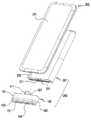
도 1은 본 고안의 다양한 실시예에 따른 접속 장치(100)를 나타내는 사시도이다. 도 2는 본 고안의 다양한 실시예에 따른 접속 장치(100)를 나타내는 측면도이다. 도 3은 본 고안의 다양한 실시예에 따른 접속 장치(100)를 나타내는 정면도이다. 도 4는 본 고안의 다양한 실시예에 따른 접속 장치(100)를 나타내는 배면도이다.1 is a perspective view illustrating a
도 1 내지 도 4를 참조하면, 본 고안의 다양한 실시예에 따른 접속 장치(100)는, 제1 몸체부(101), 제2 몸체부(102), 적어도 하나의 연결부(103) 및 복수의 접속 부재(111, 121)를 포함할 수 있다. 상기 제1 몸체부(101)와 상기 제2 몸체부(102)는 실질적으로 서로에 대하여 대칭을 이루는 형상을 가질 수 있으며, 상기 연결부(103)를 통해 연결되어 서로에 대하여 대칭을 이루게 배치될 수 있다. 한 실시예에서, 상기 제1 몸체부(101)와 상기 제2 몸체부(102)는 제1 방향, 예를 들면, 횡방향(X)으로 서로 나란하게 연장되며, 적어도 부분적으로 서로 마주보게 배치될 수 있다. 예컨대, 상기 제1 몸체부(101)와 상기 제2 몸체부(102)는 상기 횡방향(X)에 수직하는 두께 방향(Z)에서 서로 인접하게 배치(또는 배열)될 수 있다. 상기 연결부(103)는 상기 제1 몸체부(101)와 상기 제2 몸체부(102)의 양단 중 적어도 일단(at least one of both ends)을 연결할 수 있다. 본 고안의 실시예에서, 한 쌍의 상기 연결부(103)가 제공되어 상기 제1 몸체부(101)와 상기 제2 몸체부(102)의 양단이 각각 연결된 구성이 예시되고 있다.1 to 4, the
다양한 실시예에 따르면, 상기 접속 장치(100)는, 상기 제1 몸체부(101), 상기 제2 몸체부(102) 및 상기 연결부(들)(103)에 의해 적어도 부분적으로 둘러싸여 형성된 슬릿(131)을 더 포함할 수 있다. 예컨대, 상기 제1 몸체부(101), 상기 제2 몸체부(102) 및 상기 연결부(103)가 폐곡선을 이루어 상기 슬릿(131)을 형성할 수 있다. 한 실시예에서, 상기 슬릿(131)은 상기 횡방향(X)을 따라 연장된 장공(enlongated hole) 형상이면서, 상기 횡방향(X)에 수직하는 종방향(Y) 방향을 따라 상기 제1 몸체부(101)와 상기 제2 몸체부(102) 사이에서 상기 접속 장치(100)를 관통하게 형성될 수 있다.According to various embodiments, the
다양한 실시예에 따르면, 상기 접속 부재(111, 121)는, 상기 제1 몸체부(101)의 일면에 배치된 제1 접속 부재(first connecting member)(111)와 상기 제2 몸체부(102)의 일면에 배치된 제2 접속 부재(121)를 포함할 수 있다. 상기 제1 접속 부재(111)와 상기 제2 접속 부재(121)는 각각 상기 제1 몸체부(101) 또는 상기 제2 몸체부(102)의 표면에서 상기 종방향(Y)을 따라 돌출된 수 커넥터(male connector)로 이루어질 수 있다. 한 실시예에서, 상기 제2 접속 부재(121)는 상기 제1 접속 부재(111)와 나란하게, 예를 들어, 실질적으로 평행하게 위치될 수 있다. 다른 실시예에서, 상기 제1 접속 부재(111)와 상기 제2 접속 부재(121)는 각각 대칭 형상의 단면을 가질 수 있으며, 서로에 대하여 대칭을 이루게 배치될 수 있다. 예컨대, 상기 제1 접속 부재(111)와 상기 제2 접속 부재(121)는 USB-C 타입 규격을 만족하는 커넥터로 구현될 수 있다.According to various embodiments, the
다양한 실시예에 따르면, 상기 접속 장치(100)는 상기 제1 몸체부(101)의 내부에서 상기 연결부(103)들 중 하나의 내부를 경유하여 상기 제2 몸체부(102)의 내부로 연장된 배선(wiring), 예를 들면, 가요성 인쇄회로 기판(104)을 더 포함할 수 있다. 상기 제2 접속 부재(121)는 상기 가요성 인쇄회로 기판(104)을 통해 상기 제1 접속 부재(111)와 전기적으로 연결될 수 있다. 예컨대, 상기 제1 접속 부재(111)와 상기 제2 접속 부재(121) 중 하나는 제1 전자 장치에, 다른 하나는 제2 전자 장치 또는 보조 전원 장치에 각각 접속할 수 있으며, 상기 접속 장치(100)는 제1 전자 장치와 제2 전자 장치(또는 보조 전원 장치) 사이에서 데이터(또는 전원)을 전달할 수 있다. 어떤 실시예에서, 상기 접속 장치(100)는 전자 장치와 전자 장치 사이에서 전원을 전달할 수도 있다. 예컨대, 제1 전자 장치와 제2 전자 장치가 상기 접속 장치(100)를 통해 전기적으로 연결된 상태에서, 제1 전자 장치는 제2 전자 장치로 충전 전원을 공급할 수도 있다.According to various embodiments of the present disclosure, the
다양한 실시예에 따르면, 상기 제1 몸체부(101), 상기 제2 몸체부(102) 또는 상기 연결부(103)는 실질적으로 동일한 재질로 형성될 수 있으며, 설명의 간결함을 위해 상기 접속 장치(100)의 각 부분을 구분하여 명칭을 부여한 것임에 유의한다. 한 실시예에서, 상기 제1 몸체부(101), 상기 제2 몸체부(102) 또는 상기 연결부(103)는 탄성체, 예를 들면, 실리콘이나 우레탄으로 성형될 수 있다. 상기 제1 몸체부(101), 상기 제2 몸체부(102) 또는 상기 연결부(103)는 실질적으로 상기 접속 장치(100)의 외형을 형성하는 구성으로서, 외부 표면은 평면, 곡면 또는 경사면 등을 포함할 수 있다. 예컨대, 후술할 보조 전원 장치(예: 도 5 내지 도 8의 보조 전원 장치(200)의 본체(201)) 등의 외관에 대응하도록 상기 접속 장치(100)의 외형은 다양하게 설계될 수 있다.According to various embodiments of the present disclosure, the
다양한 실시예에 따르면, 상기 접속 장치(100)에 외력이 작용하면, 상기 제1 몸체부(101), 상기 제2 몸체부(102) 또는 상기 연결부(103) 중 적어도 하나가 탄성 변형되면서, 상기 제1 접속 부재(111)와 상기 제2 접속 부재(121) 사이의 간격이 조절(E)될 수 있다. 예컨대, 외력이 작용하면 상기 슬릿(131)의 크기나 형상이 변화될 수 있으며, 상기 슬릿(131)의 크기나 형상의 변화에 따라 상기 제1 접속 부재(111)와 상기 제2 접속 부재(121) 사이의 간격이 조절(E)될 수 있다. 도 3에서 점선으로 도시된 상기 제1 몸체부(101) 또는 상기 제1 접속 부재(111)는 상기 제1 몸체부(101)이 탄성 변형되었을 때의 위치를 예시한 것이다.According to various embodiments, when an external force acts on the
이하의 상세한 설명에서는, 선행 실시예와 동일하거나 선행 실시예를 통해 용이하게 이해할 수 있는 구성에 대해서는 도면의 참조번호를 선행 실시예와 동일하게 부여하거나 생략하고, 그 상세한 설명 또한 생략될 수 있다.In the following detailed description, the same reference numerals in the drawings as those in the preceding embodiments or easily understood through the preceding embodiments will be given or omitted the same as the previous embodiment, and the detailed description thereof may also be omitted.
도 5는 본 고안의 다양한 실시예에 따른 접속 장치(100)를 통해 보조 전원 장치(200)가 전자 장치(202)에 접속하는 예를 나타내는 사시도이다. 도 6은 본 고안의 다양한 실시예에 따른 접속 장치(100)를 통해 보조 전원 장치(200)가 전자 장치(202)와 접속된 모습을 나타내는 측면도이다. 도 7은 본 고안의 다양한 실시예에 따른 접속 장치(100)를 통해 보조 전원 장치(200)가 전자 장치(202)와 접속된 모습을 나타내는 저면도이다. 도 8은 본 고안의 다양한 실시예에 따른 접속 장치(100)가 보조 전원 장치(200)의 본체(201)와 결합된 모습을 나타내는 측면도이다.5 is a perspective view illustrating an example in which the
도 5 내지 도 8을 참조하면, 상기 접속 장치(100)를 포함하는 보조 전원 장치(200)는 상기 접속 장치(100)를 통해 전자 장치(202)와 전기적으로 연결되어, 상기 전자 장치(202)의 작동 전력 또는 충전 전력을 공급할 수 있다. 앞서 언급한 바와 같이, 상기 접속 장치(100)는 상기 전자 장치(202)와 다른 전자 장치를 연결할 수도 있으며, 이에 관한 상세한 설명은 생략하기로 한다.5 to 8, the
다양한 실시예에 따르면, 상기 전자 장치(202)는, 예를 들면, 디스플레이 장치(221)를 포함하는 이통통신 단말기 또는 스마트 폰으로서, 인터페이스 커넥터(223)를 포함할 수 있다. 상기 인터페이스 커넥터(223)는, 예를 들면, 상기 제1 접속 부재(111) 또는 상기 제2 접속 부재(121)에 상응하는 암 커넥터(female connector)로서, 충전 케이블 또는 데이터 케이블을 접속하는 수단을 제공할 수 있다. 예를 들어, 상기 전자 장치(202)는 상기 접속 장치(100)를 통해 상기 보조 전원 장치(200) 또는 다른 전자 장치와 접속할 수 있다.According to various embodiments, the
다양한 실시예에 따르면, 상기 보조 전원 장치(200)는 재충전 가능한 2차 전지를 내장한 본체(201)와 상기 접속 장치(100)를 포함할 수 있다. 상기 본체(201)는, 예를 들면, 상기 제1 접속 부재(111) 또는 상기 제2 접속 부재(121)에 상응하는 복수(예: 한 쌍)의 접속 홀(예: 제3 접속 부재(211))들을 포함할 수 있다. 예컨대, 상기 제3 접속 부재(211)는 암 커넥터로 구현될 수 있다. 상기 제3 접속 부재(211)들은 각각 서로 나란한 위치에 형성될 수 있다. 예컨대, 상기 제1 접속 부재(111)와 상기 제2 접속 부재(121)는 상기 제3 접속 부재(211) 중 하나에 각각 삽입됨으로써, 상기 접속 장치(100)가 상기 본체(201)에 장착(도 8 참조)될 수 있다. 상기 본체(201)에 장착된 상태에서, 상기 접속 장치(100)의 표면은 실질적으로 상기 본체(201)의 표면과 함께 동일한 평면, 경사면 또는 곡면을 이루게 위치할 수 있다. 사용자는, 별도의 파우치나 정형화되지 않은 케이블 등을 휴대하지 않더라도, 상기 접속 장치(100)를 상기 본체(201)에 결합한 상태로 상기 보조 전원 장치(200)를 편리하게 휴대할 수 있으며, 필요에 따라 상기 접속 장치(100)를 이용하여 전자 장치(202)에 충전 전력을 공급할 수 있다.According to various embodiments, the
다양한 실시예에 따르면, 상기 전자 장치(202)는 상기 본체(201)와 마주보게 위치된 상태에서, 상기 접속 장치(100)를 통해 상기 본체(201)와 전기적으로 연결될 수 있다. 예를 들어, 상기 인터페이스 커넥터(223)가 상기 제3 접속 부재(211)와 인접하게 위치한 상태에서, 상기 제1 접속 부재(111)와 상기 제2 접속 부재(121) 중 하나는 상기 인터페이스 커넥터(223)에, 다른 하나는 상기 제3 접속 부재(211) 중 하나에 각각 접속할 수 있다. 예컨대, 상기 본체(201)는 상기 접속 장치(100)를 통해 상기 전자 장치(202)에 연결되어 충전 전력을 공급할 수 있다.According to various embodiments, the
다양한 실시예에 따르면, 상기 전자 장치(202)의 두께나 상기 전자 장치(202) 상에서 상기 인터페이스 커넥터(223)가 형성된 위치에 따라, 상기 인터페이스 커넥터(223)와 상기 제3 접속 부재(211)의 상대적인 위치 또는 간격이 달라질 수 있다. 예컨대, 상기 전자 장치(202)가 상기 본체(201)와 마주보는 상태로 밀착하더라도, 상기 전자 장치(202)의 크기나 형상에 따라, 상기 인터페이스 커넥터(223)와 상기 제3 접속 부재(211) 사이의 간격은 상기 제1 접속 부재(111)와 상기 제2 접속 부재(121) 사이의 간격과 다를 수 있다. 앞서 언급한 바와 같이, 상기 접속 장치(100), 예를 들어, 상기 제1 몸체부(101), 상기 제2 몸체부(102) 또는 상기 연결부(들)(103)는 탄성 변형이 가능하여, 상기 제1 접속 부재(111)와 상기 제2 접속 부재(121)의 위치(또는 간격)는 상기 인터페이스 커넥터(223)와 상기 제3 접속 부재(211) 사이의 간격에 상응하게 조절될 수 있다.According to various embodiments, the
도 9는 본 고안의 다양한 실시예에 따른 접속 장치(100)를 포함하는 보조 전원 장치(200)의 구성을 나타내는 블록도이다.9 is a block diagram illustrating a configuration of an
도 9를 참조하면, 상기 보조 전원 장치(200)는, 상기 제3 접속 부재(211)와 2차 전지(215) 사이에 배치된 제어 회로(213)를 더 포함할 수 있다. 상기 제어 회로(213)는, 예를 들면, 과충전 방지회로, 방전(예: 충전 전력 공급) 회로 등을 포함할 수 있다. 한 실시예에서, 상기 제1 접속 부재(111)와 상기 제2 접속 부재(121)가 각각 상기 제3 접속 부재(211) 중 하나에 접속한 상태에서, 예를 들어, 사용자가 상기 접속 장치(100)를 상기 본체(201)에 결합하여 휴대한 상태에서, 상기 제어 회로(213)는 상기 2차 전지(215)의 충전 또는 방전을 차단할 수 있다.Referring to FIG. 9, the
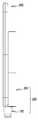
도 10과 도 11은 각각 본 고안의 다양한 실시예에 따른 접속 장치의 변형 예(1000)를 나타내는 도면이다.10 and 11 are diagrams illustrating a modified example 1000 of a connection device according to various embodiments of the present invention.
도 10과 도 11을 참조하면, 상기 접속 장치(1000)는 제1 몸체부(101)의 일단에 제공된 제1 결합 부재(1041)와 제2 몸체부(102)의 일단에 제공된 제2 결합 부재(1042)를 포함할 수 있다. 상기 제1 결합 부재(1041)와 상기 제2 결합 부재(1042)는 각각, 영구 자석(1043)(또는 자성체)이나 스냅 핏(snap-fit) 구조를 포함할 수 있다. 예컨대, 상기 제1 결합 부재(1041)와 상기 제2 결합 부재(1042)는 서로에 대하여 착탈 가능하게(attachably/detachably) 제공될 수 있다. 한 실시예에 따르면, 상기 제1 몸체부(101)의 타단과 상기 제2 몸체부(102)의 타단을 연결하는 연결부(1003)는 주름 구조(1031)를 포함할 수 있다. 예컨대, 상기 주름 구조(1031)는 상기 연결부(1003)의 내측면에 형성될 수 있다.10 and 11, the
다양한 실시예에 따르면, 상기 제1 결합 부재(1041)와 상기 제2 결합 부재(1042)가 서로 결합한 상태에서, 상기 제1 몸체부(101)와 상기 제2 몸체부(102)의 일단에서는 도 3의 연결부(103)와 유사한 연결 구조(1004)가 형성될 수 있다. 예컨대, 상기 제1 몸체부(101)와 상기 제2 몸체부(102)의 일단은 상기 연결 구조(1004)에 의해 서로 연결되며, 상기 제1 몸체부(101)와 상기 제2 몸체부(102)의 타단은 상기 연결부(1003)에 의해 연결되어 폐곡선 형상이 완성될 수 있다. 한 실시예에 따르면, 상기 제1 결합 부재(1041)와 상기 제2 결합 부재(1042)는 사용자에 의해 분리될 수 있다. 상기 제1 결합 부재(1041)가 상기 제2 결합 부재(1042)로부터 분리된 상태에서, 상기 제1 몸체부(101)와 상기 제2 몸체부(102)는 상기 연결부(1003)를 중심으로 서로에 대하여 회동(P)할 수 있다. 예컨대, 상기 제1 몸체부(101)는 상기 제2 몸체부(102)에 대하여 경사진 위치로 회동(P)할 수 있으며, 상기 제2 몸체부(102)와 대면하는 위치로부터 180도 각도 위치 또는 그 이상의 각도 위치까지 회동할 수 있다. 다른 실시예에서, 상기 제1 몸체부(101)가 상기 제2 몸체부(102)에 대하여 회동할 때, 상기 주름 구조(1031)는 수축 또는 확장될 수 있다. 예컨대, 상기 주름 구조(1031)는 상기 제2 몸체부(102)에 대하여 상기 제1 몸체부(101)가 원활하게 회동할 수 있는 환경(또는 조건)을 제공할 수 있다.According to various embodiments of the present disclosure, the
다양한 실시예에 따르면, 도 10에 도시된 바와 같이, 상기 제1 결합 부재(1041)와 상기 제2 결합 부재(1042)가 상기 연결 구조(1004)를 형성한 상태에서, 상기 접속 장치(1000)는 전자 장치와 보조 전원 장치의 본체를 서로 마주보게 밀착한 상태로 접속시킬 수 있다. 예컨대, 상기 제1 결합 부재(1041)와 상기 제2 결합 부재(1042)가 상기 연결 구조(1004)를 형성한 상태에서, 상기 접속 장치(1000)는 실질적으로 도 7에 도시된 접속 장치(100)와 동일하게 전자 장치와 보조 전원 장치의 본체를 전기적으로 연결시킬 수 있다. 한 실시예에서, 상기 제1 몸체부(101)가 상기 제2 몸체부(102)와 180도 각도를 이루게 배치된 상태라면, 전자 장치(예: 도 5의 전자 장치(202))와 보조 전원 장치의 본체(예: 도 5의 본체(201))는 서로의 일측에 나란하게 위치한 상태에서 상기 접속 장치(1000)를 통해 전기적으로 연결될 수 있다. 예컨대, 본 고안의 다양한 실시예에 따른 접속 장치(1000)는, 전자 장치와 보조 전원 장치의 본체가 서로 마주보는 상태로 밀착한 위치 또는 서로의 일측에 나란하게 배치된 위치에서 보조 전원 장치의 본체를 전자 장치에 접속시킬 수 있다.According to various embodiments of the present disclosure, as shown in FIG. 10, in the state where the
상술한 바와 같이, 본 고안의 다양한 실시예에 따르면, 접속 장치(예: 도 1 또는 도 11의 접속 장치(100, 1000)는, 적어도 부분적으로 서로 마주보게 배치되고, 서로 나란하게 연장된 제1 몸체부(first body portion)와 제2 몸체부(예: 도 1의 제1 몸체부(101)와 제2 몸체부(102))와, 상기 제1 몸체부의 일면에 배치된 제1 접속 부재(first connecting member)(예: 도 1의 제1 접속 부재(111))와, 상기 제2 몸체부의 일면에 배치되어 상기 제1 접속 부재와 나란하게 위치된 제2 접속 부재(예: 도 1의 제2 접속 부재(121))와, 상기 제1 몸체부와 상기 제2 몸체부의 양단 중 적어도 일단(at least one of both ends)을 연결하는 연결부(예: 도 1 또는 도 11의 연결부(103, 1003))를 포함하고, 상기 제1 몸체부, 상기 제2 몸체부 또는 상기 연결부 중 적어도 하나가 탄성 변형되어 상기 제1 접속 부재와 상기 제2 접속 부재 사이의 간격을 조절할 수 있다.As described above, according to various embodiments of the present invention, a connection device (eg, the
다양한 실시예에 따르면, 상기 제1 몸체부의 내부에서 상기 연결부의 내부를 경유하여 상기 제2 몸체부의 내부로 연장된 가요성 인쇄회로 기판(예: 도 3의 가요성 인쇄회로 기판(104))을 더 포함하고, 상기 가요성 인쇄회로 기판을 통해 상기 제2 접속 부재가 상기 제1 접속 부재와 전기적으로 연결될 수 있다.According to various embodiments of the present disclosure, a flexible printed circuit board (eg, the flexible printed
다양한 실시예에 따르면, 상기 제1 접속 부재는 상기 제1 몸체부의 한 면에서 돌출되고, 상기 제2 접속 부재는 상기 제2 몸체부의 한 면에서 상기 제1 접속 부재와 나란하게 돌출될 수 있다.According to various embodiments of the present disclosure, the first connection member may protrude from one surface of the first body portion, and the second connection member may protrude parallel to the first connection member from one surface of the second body portion.
다양한 실시예에 따르면, 상기 연결부가 상기 제1 몸체부와 상기 제2 몸체부의 양단에 각각 제공되어 상기 제1 몸체부와 상기 제2 몸체부를 연결함으로써 상기와 같은 접속 장치는 폐곡선 형상을 가질 수 있다.According to various embodiments of the present disclosure, the connection device may be provided at both ends of the first body part and the second body part to connect the first body part and the second body part, and thus the connection device may have a closed curve shape. .
다양한 실시예에 따르면, 상기와 같은 접속 장치는, 상기 제1 몸체부, 상기 제2 몸체부 및 상기 연결부들에 의해 둘러싸여 형성된 슬릿(예: 도 1의 슬릿(131))을 더 포함할 수 있다.According to various embodiments of the present disclosure, the connection device may further include a slit (eg, the
다양한 실시예에 따르면, 상기 제1 접속 부재는 상기 제1 몸체부의 한 면에서 돌출되고, 상기 제2 접속 부재는 상기 제2 몸체부의 한 면에서 상기 제1 접속 부재와 나란하게 돌출되며, 상기 슬릿은 상기 제1 접속 부재 또는 상기 제2 접속 부재가 돌출된 방향에 대하여 수직 방향으로 연장된 장공(enlongated hole) 형상을 가질 수 있다.According to various embodiments, the first connecting member protrudes from one side of the first body portion, and the second connecting member protrudes from the one side of the second body portion in parallel with the first connecting member, and the slit May have an elongated hole shape extending in a direction perpendicular to the direction in which the first connection member or the second connection member protrudes.
다양한 실시예에 따르면, 상기와 같은 접속 장치는, 상기 제1 몸체부의 일단에 제공된 제1 결합 부재(예: 도 11의 제1 결합 부재(1041)); 및 상기 제2 몸체부의 일단에 제공된 제2 결합 부재(예: 도 11의 제2 결합 부재(1042))를 더 포함하고, 상기 제1 결합 부재가 상기 제2 결합 부재와 착탈 가능하게(attachably/detachably) 제공될 수 있다.According to various embodiments, the connection device may include a first coupling member (eg, the
다양한 실시예에 따르면, 상기 연결부는 상기 제1 몸체부의 타단을 상기 제2 몸체부의 타단에 연결하며, 내측면에 형성된 주름 구조(예: 도 11의 주름 구조(1031))를 포함할 수 있다.According to various embodiments of the present disclosure, the connection part may connect the other end of the first body part to the other end of the second body part and include a wrinkle structure (for example, the
다양한 실시예에 따르면, 상기 제1 결합 부재가 상기 제2 결합 부재로부터 분리된 상태에서 상기 제1 몸체부와 상기 제2 몸체부는 상기 연결부를 중심으로 서로에 대하여 회동할 수 있다.According to various embodiments of the present disclosure, the first body portion and the second body portion may be rotated with respect to each other with respect to the connection portion in a state where the first coupling member is separated from the second coupling member.
본 고안의 다양한 실시예에 따르면, 보조 전원 장치는, 일면에 한 쌍의 접속 홀(예: 도 5의 제3 접속 부재(211))이 형성된 본체(예: 도 5의 본체(201))와, 상술한 접속 장치(예: 도 5의 접속 장치(100))를 포함하고, 상기 제1 접속 부재와 상기 제2 접속 부재가 상기 접속 홀들 중 하나에 각각 결합함으로써, 상기 접속 장치가 상기 본체와 결합할 수 있다.According to various embodiments of the present invention, the auxiliary power supply may include a main body (for example, the
다양한 실시예에 따르면, 상기 본체는 재충전 가능한 2차 전지(예: 도 9의 2차 전자(215))를 내장할 수 있다.According to various embodiments, the main body may contain a rechargeable secondary battery (eg, the
다양한 실시예에 따르면, 상기와 같은 보조 전원 장치는 제어 회로(예: 도 9의 제어 회로(213))를 더 포함하고, 상기 제1 접속 부재와 상기 제2 접속 부재가 상기 접속 홀들 중 하나에 각각 결합한 상태에서, 상기 제어 회로가 상기 2차 전지의 충전 또는 방전을 차단할 수 있다.According to various embodiments of the present disclosure, the auxiliary power supply further includes a control circuit (eg, the
이상, 본 고안의 상세한 설명에서는 구체적인 실시 예에 관해서 설명하였으나, 본 고안의 범위에서 벗어나지 않는 한도 내에서 여러 가지 변형이 가능함은 당해 분야에서 통상의 지식을 가진 자에게 있어서 자명하다 할 것이다.As described above, in the detailed description of the present invention, specific embodiments have been described, but it will be apparent to those skilled in the art that various modifications are possible without departing from the scope of the present invention.
100: 접속 장치 101: 제1 몸체부
102: 제2 몸체부 103: 연결부
111: 제1 접속 부재 121: 제2 접속 부재
131: 슬릿 200: 보조 전원 장치
201: 본체 211: 접속홀100: connecting device 101: first body portion
102: second body portion 103: connecting portion
111: first connecting member 121: second connecting member
131: slit 200: auxiliary power supply
201: main body 211: connection hole
Claims (12)
Translated fromKorean적어도 부분적으로 서로 마주보게 배치되고, 서로 나란하게 연장된 제1 몸체부(first body portion)와 제2 몸체부;
상기 제1 몸체부의 일면에 배치된 제1 접속 부재(first connecting member);
상기 제2 몸체부의 일면에 배치되어 상기 제1 접속 부재와 나란하게 위치된 제2 접속 부재; 및
상기 제1 몸체부와 상기 제2 몸체부의 양단 중 적어도 일단(at least one of both ends)을 연결하는 연결부를 포함하고,
상기 제1 몸체부, 상기 제2 몸체부 또는 상기 연결부 중 적어도 하나가 탄성 변형되어 상기 제1 접속 부재와 상기 제2 접속 부재 사이의 간격을 조절하는 접속 장치.
In the connecting device,
A first body portion and a second body portion disposed at least partially facing each other and extending in parallel with each other;
A first connecting member disposed on one surface of the first body portion;
A second connecting member disposed on one surface of the second body portion and positioned in parallel with the first connecting member; And
A connecting portion connecting at least one of both ends of the first body portion and the second body portion,
At least one of the first body portion, the second body portion, or the connection portion is elastically deformed to adjust the distance between the first connection member and the second connection member.
상기 제1 몸체부의 내부에서 상기 연결부의 내부를 경유하여 상기 제2 몸체부의 내부로 연장된 가요성 인쇄회로 기판을 더 포함하고,
상기 가요성 인쇄회로 기판을 통해 상기 제2 접속 부재가 상기 제1 접속 부재와 전기적으로 연결된 접속 장치.
According to claim 1,
And a flexible printed circuit board extending from the inside of the first body portion to the inside of the second body portion via the inside of the connection portion.
And a second connecting member electrically connected to the first connecting member through the flexible printed circuit board.
The connecting device according to claim 1, wherein the first connecting member protrudes from one side of the first body portion, and the second connecting member protrudes from the one side of the second body portion in parallel with the first connecting member.
상기 연결부가 상기 제1 몸체부와 상기 제2 몸체부의 양단에 각각 제공되어 상기 제1 몸체부와 상기 제2 몸체부를 연결함으로써 폐곡선 형상을 가진 접속 장치.
According to claim 1,
And a connection part provided at both ends of the first body part and the second body part to connect the first body part and the second body part to have a closed curve shape.
상기 제1 몸체부, 상기 제2 몸체부 및 상기 연결부들에 의해 둘러싸여 형성된 슬릿을 더 포함하는 접속 장치.
The method of claim 4, wherein
And a slit formed by the first body part, the second body part, and the connection parts.
상기 제1 접속 부재는 상기 제1 몸체부의 한 면에서 돌출되고, 상기 제2 접속 부재는 상기 제2 몸체부의 한 면에서 상기 제1 접속 부재와 나란하게 돌출되며,
상기 슬릿은 상기 제1 접속 부재 또는 상기 제2 접속 부재가 돌출된 방향에 대하여 수직 방향으로 연장된 장공(enlongated hole) 형상을 가진 접속 장치.
The method of claim 5,
The first connection member protrudes from one side of the first body portion, and the second connection member protrudes from the one side of the second body portion in parallel with the first connection member.
And the slit has an elongated hole shape extending in a direction perpendicular to a direction in which the first connecting member or the second connecting member protrudes.
상기 제1 몸체부의 일단에 제공된 제1 결합 부재; 및
상기 제2 몸체부의 일단에 제공된 제2 결합 부재를 더 포함하고,
상기 제1 결합 부재가 상기 제2 결합 부재와 착탈 가능하게(attachably/detachably) 제공된 접속 장치.
According to claim 1,
A first coupling member provided at one end of the first body portion; And
Further comprising a second coupling member provided at one end of the second body portion,
And the first coupling member is attachably / detachably provided with the second coupling member.
상기 연결부는 상기 제1 몸체부의 타단을 상기 제2 몸체부의 타단에 연결하며, 내측면에 형성된 주름 구조를 포함하는 접속 장치.
The method of claim 7, wherein
The connecting part connects the other end of the first body portion to the other end of the second body portion, the connection device comprising a corrugated structure formed on the inner surface.
The connecting device according to claim 8, wherein the first body portion and the second body portion pivot about each other with respect to the connecting portion in a state where the first coupling member is separated from the second coupling member.
일면에 한 쌍의 접속 홀이 형성된 본체; 및
제1 항 내지 제9 항 중 어느 한 항에 따른 접속 장치를 포함하고,
상기 제1 접속 부재와 상기 제2 접속 부재가 상기 접속 홀들 중 하나에 각각 결합함으로써, 상기 접속 장치가 상기 본체와 결합하는 보조 전원 장치.
In the auxiliary power supply,
A main body having a pair of connection holes formed on one surface thereof; And
A connecting device according to any one of claims 1 to 9,
And the first connecting member and the second connecting member are respectively coupled to one of the connecting holes, so that the connecting device is coupled to the main body.
The auxiliary power supply of claim 10, wherein the main body includes a rechargeable secondary battery.
제어 회로를 더 포함하고,
상기 제1 접속 부재와 상기 제2 접속 부재가 상기 접속 홀들 중 하나에 각각 결합한 상태에서, 상기 제어 회로는 상기 2차 전지의 충전 또는 방전을 차단하는 보조 전원 장치.The method of claim 10,
Further comprising a control circuit,
And the control circuit blocks charging or discharging of the secondary battery in a state in which the first connection member and the second connection member are respectively coupled to one of the connection holes.
Priority Applications (1)
| Application Number | Priority Date | Filing Date | Title |
|---|---|---|---|
| KR2020180003049UKR200497166Y1 (en) | 2018-07-03 | 2018-07-03 | Connecting device and auxiliary power supply |
Applications Claiming Priority (1)
| Application Number | Priority Date | Filing Date | Title |
|---|---|---|---|
| KR2020180003049UKR200497166Y1 (en) | 2018-07-03 | 2018-07-03 | Connecting device and auxiliary power supply |
Publications (2)
| Publication Number | Publication Date |
|---|---|
| KR20200000091Utrue KR20200000091U (en) | 2020-01-13 |
| KR200497166Y1 KR200497166Y1 (en) | 2023-08-18 |
Family
ID=69155811
Family Applications (1)
| Application Number | Title | Priority Date | Filing Date |
|---|---|---|---|
| KR2020180003049UActiveKR200497166Y1 (en) | 2018-07-03 | 2018-07-03 | Connecting device and auxiliary power supply |
Country Status (1)
| Country | Link |
|---|---|
| KR (1) | KR200497166Y1 (en) |
Citations (5)
| Publication number | Priority date | Publication date | Assignee | Title |
|---|---|---|---|---|
| KR20150113729A (en)* | 2014-03-31 | 2015-10-08 | 이건일 | Apparatus for Assisting External Interface of Mobile Device |
| KR101592113B1 (en)* | 2014-08-14 | 2016-02-04 | 엘지전자 주식회사 | Mobile terminal |
| US20160197445A1 (en)* | 2015-01-02 | 2016-07-07 | Zound Industries International Ab | Building set for organizing electronic items, or accessories |
| KR200481073Y1 (en)* | 2015-10-30 | 2016-08-09 | 김계숙 | Contact type supplementary battery |
| KR20170116953A (en)* | 2017-03-31 | 2017-10-20 | 김재문 | Assist battery pack for mobile |
- 2018
- 2018-07-03KRKR2020180003049Upatent/KR200497166Y1/enactiveActive
Patent Citations (5)
| Publication number | Priority date | Publication date | Assignee | Title |
|---|---|---|---|---|
| KR20150113729A (en)* | 2014-03-31 | 2015-10-08 | 이건일 | Apparatus for Assisting External Interface of Mobile Device |
| KR101592113B1 (en)* | 2014-08-14 | 2016-02-04 | 엘지전자 주식회사 | Mobile terminal |
| US20160197445A1 (en)* | 2015-01-02 | 2016-07-07 | Zound Industries International Ab | Building set for organizing electronic items, or accessories |
| KR200481073Y1 (en)* | 2015-10-30 | 2016-08-09 | 김계숙 | Contact type supplementary battery |
| KR20170116953A (en)* | 2017-03-31 | 2017-10-20 | 김재문 | Assist battery pack for mobile |
Also Published As
| Publication number | Publication date |
|---|---|
| KR200497166Y1 (en) | 2023-08-18 |
Similar Documents
| Publication | Publication Date | Title |
|---|---|---|
| US6937468B2 (en) | Portable computer and portable docking station arrangement | |
| US9502817B2 (en) | Connection device for portable terminal | |
| US7743999B1 (en) | Case for portable electronic device having external access port | |
| US20050255895A1 (en) | Adaptable charging cradle with speaker for portable communication devices | |
| US20070042821A1 (en) | Wrist watch-type headset assembly | |
| US20170264991A1 (en) | Headphone or earphone assembly having a pivotable usb charging connector integrated into a housing thereof | |
| US8142230B2 (en) | Earphone assembly and electronic device using the same | |
| US6926554B2 (en) | Portable device connection apparatus and system | |
| US9160826B2 (en) | Docking station for portable communication device | |
| US10061351B2 (en) | Portable user device | |
| US9502915B2 (en) | Charging and discharging apparatus and terminal | |
| KR101756476B1 (en) | Contact terminal for portable terminal | |
| US20170346321A1 (en) | Disposable Charger for a Mobile Electronic Device | |
| US9793641B1 (en) | Plug receptacle for an electronic device | |
| US7242588B2 (en) | Multifunction modular electronic apparatus | |
| JP4972697B2 (en) | Electronic equipment | |
| KR20200000091U (en) | Connecting device and auxiliary power supply | |
| KR20140001056U (en) | Auxiliary power providing device | |
| KR101397859B1 (en) | Assembly structure of battery for portable terminal | |
| CN102593877A (en) | Wireless Charging Receiver for Portable Electronic Devices | |
| US20090113103A1 (en) | Cascade type charge assembly | |
| US20200366109A1 (en) | Portable power bank | |
| KR200212929Y1 (en) | Belt-shaped battery | |
| KR200385075Y1 (en) | Container structure of electric charging connector for mobile phone | |
| CN205004766U (en) | Portable charging device is used to smart card |
Legal Events
| Date | Code | Title | Description |
|---|---|---|---|
| UA0108 | Application for utility model registration | St.27 status event code:A-0-1-A10-A12-nap-UA0108 | |
| UG1501 | Laying open of application | St.27 status event code:A-1-1-Q10-Q12-nap-UG1501 | |
| A201 | Request for examination | ||
| UA0201 | Request for examination | St.27 status event code:A-1-2-D10-D11-exm-UA0201 | |
| D13-X000 | Search requested | St.27 status event code:A-1-2-D10-D13-srh-X000 | |
| D14-X000 | Search report completed | St.27 status event code:A-1-2-D10-D14-srh-X000 | |
| E902 | Notification of reason for refusal | ||
| UE0902 | Notice of grounds for rejection | St.27 status event code:A-1-2-D10-D21-exm-UE0902 | |
| P11-X000 | Amendment of application requested | St.27 status event code:A-2-2-P10-P11-nap-X000 | |
| P13-X000 | Application amended | St.27 status event code:A-2-2-P10-P13-nap-X000 | |
| E701 | Decision to grant or registration of patent right | ||
| UE0701 | Decision of registration | St.27 status event code:A-1-2-D10-D22-exm-UE0701 | |
| UR0701 | Registration of establishment | St.27 status event code:A-2-4-F10-F11-exm-UR0701 | |
| UR1002 | Payment of registration fee | St.27 status event code:A-2-2-U10-U11-oth-UR1002 Fee payment year number:1 | |
| UG1601 | Publication of registration | St.27 status event code:A-4-4-Q10-Q13-nap-UG1601 |