KR20190140807A - Positioning conveyance mechanism and positioning conveyance production system - Google Patents
Positioning conveyance mechanism and positioning conveyance production systemDownload PDFInfo
- Publication number
- KR20190140807A KR20190140807AKR1020180117447AKR20180117447AKR20190140807AKR 20190140807 AKR20190140807 AKR 20190140807AKR 1020180117447 AKR1020180117447 AKR 1020180117447AKR 20180117447 AKR20180117447 AKR 20180117447AKR 20190140807 AKR20190140807 AKR 20190140807A
- Authority
- KR
- South Korea
- Prior art keywords
- clamping
- conveyor
- positioning
- sliding block
- positioning clamping
- Prior art date
- Legal status (The legal status is an assumption and is not a legal conclusion. Google has not performed a legal analysis and makes no representation as to the accuracy of the status listed.)
- Ceased
Links
- 230000007246mechanismEffects0.000titleclaimsabstractdescription68
- 238000004519manufacturing processMethods0.000titleclaimsabstractdescription49
- 238000000034methodMethods0.000claimsdescription30
- 230000032258transportEffects0.000description10
- 230000008569processEffects0.000description7
- 235000012431wafersNutrition0.000description7
- 238000009434installationMethods0.000description4
- 238000005259measurementMethods0.000description4
- 229910000831SteelInorganic materials0.000description2
- 230000000694effectsEffects0.000description2
- 239000000463materialSubstances0.000description2
- 239000010959steelSubstances0.000description2
- 238000003466weldingMethods0.000description2
- 238000005034decorationMethods0.000description1
- 230000007547defectEffects0.000description1
- 230000002950deficientEffects0.000description1
- 238000009826distributionMethods0.000description1
- 238000003384imaging methodMethods0.000description1
- 238000012986modificationMethods0.000description1
- 230000004048modificationEffects0.000description1
- 230000000007visual effectEffects0.000description1
- 239000002699waste materialSubstances0.000description1
Images


Classifications
- H—ELECTRICITY
- H01—ELECTRIC ELEMENTS
- H01L—SEMICONDUCTOR DEVICES NOT COVERED BY CLASS H10
- H01L21/00—Processes or apparatus adapted for the manufacture or treatment of semiconductor or solid state devices or of parts thereof
- H01L21/67—Apparatus specially adapted for handling semiconductor or electric solid state devices during manufacture or treatment thereof; Apparatus specially adapted for handling wafers during manufacture or treatment of semiconductor or electric solid state devices or components ; Apparatus not specifically provided for elsewhere
- H01L21/677—Apparatus specially adapted for handling semiconductor or electric solid state devices during manufacture or treatment thereof; Apparatus specially adapted for handling wafers during manufacture or treatment of semiconductor or electric solid state devices or components ; Apparatus not specifically provided for elsewhere for conveying, e.g. between different workstations
- H01L21/67703—Apparatus specially adapted for handling semiconductor or electric solid state devices during manufacture or treatment thereof; Apparatus specially adapted for handling wafers during manufacture or treatment of semiconductor or electric solid state devices or components ; Apparatus not specifically provided for elsewhere for conveying, e.g. between different workstations between different workstations
- H01L21/67727—Apparatus specially adapted for handling semiconductor or electric solid state devices during manufacture or treatment thereof; Apparatus specially adapted for handling wafers during manufacture or treatment of semiconductor or electric solid state devices or components ; Apparatus not specifically provided for elsewhere for conveying, e.g. between different workstations between different workstations using a general scheme of a conveying path within a factory
- H—ELECTRICITY
- H01—ELECTRIC ELEMENTS
- H01L—SEMICONDUCTOR DEVICES NOT COVERED BY CLASS H10
- H01L21/00—Processes or apparatus adapted for the manufacture or treatment of semiconductor or solid state devices or of parts thereof
- H01L21/67—Apparatus specially adapted for handling semiconductor or electric solid state devices during manufacture or treatment thereof; Apparatus specially adapted for handling wafers during manufacture or treatment of semiconductor or electric solid state devices or components ; Apparatus not specifically provided for elsewhere
- H01L21/67005—Apparatus not specifically provided for elsewhere
- H01L21/67011—Apparatus for manufacture or treatment
- H01L21/67155—Apparatus for manufacturing or treating in a plurality of work-stations
- H01L21/67161—Apparatus for manufacturing or treating in a plurality of work-stations characterized by the layout of the process chambers
- H01L21/67173—Apparatus for manufacturing or treating in a plurality of work-stations characterized by the layout of the process chambers in-line arrangement
- B—PERFORMING OPERATIONS; TRANSPORTING
- B65—CONVEYING; PACKING; STORING; HANDLING THIN OR FILAMENTARY MATERIAL
- B65G—TRANSPORT OR STORAGE DEVICES, e.g. CONVEYORS FOR LOADING OR TIPPING, SHOP CONVEYOR SYSTEMS OR PNEUMATIC TUBE CONVEYORS
- B65G47/00—Article or material-handling devices associated with conveyors; Methods employing such devices
- H—ELECTRICITY
- H01—ELECTRIC ELEMENTS
- H01L—SEMICONDUCTOR DEVICES NOT COVERED BY CLASS H10
- H01L21/00—Processes or apparatus adapted for the manufacture or treatment of semiconductor or solid state devices or of parts thereof
- H01L21/67—Apparatus specially adapted for handling semiconductor or electric solid state devices during manufacture or treatment thereof; Apparatus specially adapted for handling wafers during manufacture or treatment of semiconductor or electric solid state devices or components ; Apparatus not specifically provided for elsewhere
- H01L21/68—Apparatus specially adapted for handling semiconductor or electric solid state devices during manufacture or treatment thereof; Apparatus specially adapted for handling wafers during manufacture or treatment of semiconductor or electric solid state devices or components ; Apparatus not specifically provided for elsewhere for positioning, orientation or alignment
- B—PERFORMING OPERATIONS; TRANSPORTING
- B65—CONVEYING; PACKING; STORING; HANDLING THIN OR FILAMENTARY MATERIAL
- B65G—TRANSPORT OR STORAGE DEVICES, e.g. CONVEYORS FOR LOADING OR TIPPING, SHOP CONVEYOR SYSTEMS OR PNEUMATIC TUBE CONVEYORS
- B65G49/00—Conveying systems characterised by their application for specified purposes not otherwise provided for
- B65G49/05—Conveying systems characterised by their application for specified purposes not otherwise provided for for fragile or damageable materials or articles
- B65G49/06—Conveying systems characterised by their application for specified purposes not otherwise provided for for fragile or damageable materials or articles for fragile sheets, e.g. glass
- B65G49/061—Lifting, gripping, or carrying means, for one or more sheets forming independent means of transport, e.g. suction cups, transport frames
- H—ELECTRICITY
- H01—ELECTRIC ELEMENTS
- H01L—SEMICONDUCTOR DEVICES NOT COVERED BY CLASS H10
- H01L21/00—Processes or apparatus adapted for the manufacture or treatment of semiconductor or solid state devices or of parts thereof
- H01L21/67—Apparatus specially adapted for handling semiconductor or electric solid state devices during manufacture or treatment thereof; Apparatus specially adapted for handling wafers during manufacture or treatment of semiconductor or electric solid state devices or components ; Apparatus not specifically provided for elsewhere
- H01L21/67005—Apparatus not specifically provided for elsewhere
- H01L21/67242—Apparatus for monitoring, sorting or marking
- H01L21/67259—Position monitoring, e.g. misposition detection or presence detection
- H—ELECTRICITY
- H01—ELECTRIC ELEMENTS
- H01L—SEMICONDUCTOR DEVICES NOT COVERED BY CLASS H10
- H01L21/00—Processes or apparatus adapted for the manufacture or treatment of semiconductor or solid state devices or of parts thereof
- H01L21/67—Apparatus specially adapted for handling semiconductor or electric solid state devices during manufacture or treatment thereof; Apparatus specially adapted for handling wafers during manufacture or treatment of semiconductor or electric solid state devices or components ; Apparatus not specifically provided for elsewhere
- H01L21/67005—Apparatus not specifically provided for elsewhere
- H01L21/67242—Apparatus for monitoring, sorting or marking
- H01L21/67271—Sorting devices
- H—ELECTRICITY
- H01—ELECTRIC ELEMENTS
- H01L—SEMICONDUCTOR DEVICES NOT COVERED BY CLASS H10
- H01L21/00—Processes or apparatus adapted for the manufacture or treatment of semiconductor or solid state devices or of parts thereof
- H01L21/67—Apparatus specially adapted for handling semiconductor or electric solid state devices during manufacture or treatment thereof; Apparatus specially adapted for handling wafers during manufacture or treatment of semiconductor or electric solid state devices or components ; Apparatus not specifically provided for elsewhere
- H01L21/677—Apparatus specially adapted for handling semiconductor or electric solid state devices during manufacture or treatment thereof; Apparatus specially adapted for handling wafers during manufacture or treatment of semiconductor or electric solid state devices or components ; Apparatus not specifically provided for elsewhere for conveying, e.g. between different workstations
- H01L21/67703—Apparatus specially adapted for handling semiconductor or electric solid state devices during manufacture or treatment thereof; Apparatus specially adapted for handling wafers during manufacture or treatment of semiconductor or electric solid state devices or components ; Apparatus not specifically provided for elsewhere for conveying, e.g. between different workstations between different workstations
- H01L21/67706—Mechanical details, e.g. roller, belt
- H—ELECTRICITY
- H01—ELECTRIC ELEMENTS
- H01L—SEMICONDUCTOR DEVICES NOT COVERED BY CLASS H10
- H01L21/00—Processes or apparatus adapted for the manufacture or treatment of semiconductor or solid state devices or of parts thereof
- H01L21/67—Apparatus specially adapted for handling semiconductor or electric solid state devices during manufacture or treatment thereof; Apparatus specially adapted for handling wafers during manufacture or treatment of semiconductor or electric solid state devices or components ; Apparatus not specifically provided for elsewhere
- H01L21/677—Apparatus specially adapted for handling semiconductor or electric solid state devices during manufacture or treatment thereof; Apparatus specially adapted for handling wafers during manufacture or treatment of semiconductor or electric solid state devices or components ; Apparatus not specifically provided for elsewhere for conveying, e.g. between different workstations
- H01L21/67703—Apparatus specially adapted for handling semiconductor or electric solid state devices during manufacture or treatment thereof; Apparatus specially adapted for handling wafers during manufacture or treatment of semiconductor or electric solid state devices or components ; Apparatus not specifically provided for elsewhere for conveying, e.g. between different workstations between different workstations
- H01L21/67709—Apparatus specially adapted for handling semiconductor or electric solid state devices during manufacture or treatment thereof; Apparatus specially adapted for handling wafers during manufacture or treatment of semiconductor or electric solid state devices or components ; Apparatus not specifically provided for elsewhere for conveying, e.g. between different workstations between different workstations using magnetic elements
- H—ELECTRICITY
- H01—ELECTRIC ELEMENTS
- H01L—SEMICONDUCTOR DEVICES NOT COVERED BY CLASS H10
- H01L21/00—Processes or apparatus adapted for the manufacture or treatment of semiconductor or solid state devices or of parts thereof
- H01L21/67—Apparatus specially adapted for handling semiconductor or electric solid state devices during manufacture or treatment thereof; Apparatus specially adapted for handling wafers during manufacture or treatment of semiconductor or electric solid state devices or components ; Apparatus not specifically provided for elsewhere
- H01L21/677—Apparatus specially adapted for handling semiconductor or electric solid state devices during manufacture or treatment thereof; Apparatus specially adapted for handling wafers during manufacture or treatment of semiconductor or electric solid state devices or components ; Apparatus not specifically provided for elsewhere for conveying, e.g. between different workstations
- H01L21/67703—Apparatus specially adapted for handling semiconductor or electric solid state devices during manufacture or treatment thereof; Apparatus specially adapted for handling wafers during manufacture or treatment of semiconductor or electric solid state devices or components ; Apparatus not specifically provided for elsewhere for conveying, e.g. between different workstations between different workstations
- H01L21/67715—Changing the direction of the conveying path
- H—ELECTRICITY
- H01—ELECTRIC ELEMENTS
- H01L—SEMICONDUCTOR DEVICES NOT COVERED BY CLASS H10
- H01L21/00—Processes or apparatus adapted for the manufacture or treatment of semiconductor or solid state devices or of parts thereof
- H01L21/67—Apparatus specially adapted for handling semiconductor or electric solid state devices during manufacture or treatment thereof; Apparatus specially adapted for handling wafers during manufacture or treatment of semiconductor or electric solid state devices or components ; Apparatus not specifically provided for elsewhere
- H01L21/677—Apparatus specially adapted for handling semiconductor or electric solid state devices during manufacture or treatment thereof; Apparatus specially adapted for handling wafers during manufacture or treatment of semiconductor or electric solid state devices or components ; Apparatus not specifically provided for elsewhere for conveying, e.g. between different workstations
- H01L21/67703—Apparatus specially adapted for handling semiconductor or electric solid state devices during manufacture or treatment thereof; Apparatus specially adapted for handling wafers during manufacture or treatment of semiconductor or electric solid state devices or components ; Apparatus not specifically provided for elsewhere for conveying, e.g. between different workstations between different workstations
- H01L21/67718—Changing orientation of the substrate, e.g. from a horizontal position to a vertical position
- H—ELECTRICITY
- H01—ELECTRIC ELEMENTS
- H01L—SEMICONDUCTOR DEVICES NOT COVERED BY CLASS H10
- H01L21/00—Processes or apparatus adapted for the manufacture or treatment of semiconductor or solid state devices or of parts thereof
- H01L21/67—Apparatus specially adapted for handling semiconductor or electric solid state devices during manufacture or treatment thereof; Apparatus specially adapted for handling wafers during manufacture or treatment of semiconductor or electric solid state devices or components ; Apparatus not specifically provided for elsewhere
- H01L21/677—Apparatus specially adapted for handling semiconductor or electric solid state devices during manufacture or treatment thereof; Apparatus specially adapted for handling wafers during manufacture or treatment of semiconductor or electric solid state devices or components ; Apparatus not specifically provided for elsewhere for conveying, e.g. between different workstations
- H01L21/67739—Apparatus specially adapted for handling semiconductor or electric solid state devices during manufacture or treatment thereof; Apparatus specially adapted for handling wafers during manufacture or treatment of semiconductor or electric solid state devices or components ; Apparatus not specifically provided for elsewhere for conveying, e.g. between different workstations into and out of processing chamber
- H01L21/67748—Apparatus specially adapted for handling semiconductor or electric solid state devices during manufacture or treatment thereof; Apparatus specially adapted for handling wafers during manufacture or treatment of semiconductor or electric solid state devices or components ; Apparatus not specifically provided for elsewhere for conveying, e.g. between different workstations into and out of processing chamber horizontal transfer of a single workpiece
- H—ELECTRICITY
- H01—ELECTRIC ELEMENTS
- H01L—SEMICONDUCTOR DEVICES NOT COVERED BY CLASS H10
- H01L21/00—Processes or apparatus adapted for the manufacture or treatment of semiconductor or solid state devices or of parts thereof
- H01L21/67—Apparatus specially adapted for handling semiconductor or electric solid state devices during manufacture or treatment thereof; Apparatus specially adapted for handling wafers during manufacture or treatment of semiconductor or electric solid state devices or components ; Apparatus not specifically provided for elsewhere
- H01L21/677—Apparatus specially adapted for handling semiconductor or electric solid state devices during manufacture or treatment thereof; Apparatus specially adapted for handling wafers during manufacture or treatment of semiconductor or electric solid state devices or components ; Apparatus not specifically provided for elsewhere for conveying, e.g. between different workstations
- H01L21/67739—Apparatus specially adapted for handling semiconductor or electric solid state devices during manufacture or treatment thereof; Apparatus specially adapted for handling wafers during manufacture or treatment of semiconductor or electric solid state devices or components ; Apparatus not specifically provided for elsewhere for conveying, e.g. between different workstations into and out of processing chamber
- H01L21/6776—Continuous loading and unloading into and out of a processing chamber, e.g. transporting belts within processing chambers
- H—ELECTRICITY
- H01—ELECTRIC ELEMENTS
- H01L—SEMICONDUCTOR DEVICES NOT COVERED BY CLASS H10
- H01L21/00—Processes or apparatus adapted for the manufacture or treatment of semiconductor or solid state devices or of parts thereof
- H01L21/67—Apparatus specially adapted for handling semiconductor or electric solid state devices during manufacture or treatment thereof; Apparatus specially adapted for handling wafers during manufacture or treatment of semiconductor or electric solid state devices or components ; Apparatus not specifically provided for elsewhere
- H01L21/677—Apparatus specially adapted for handling semiconductor or electric solid state devices during manufacture or treatment thereof; Apparatus specially adapted for handling wafers during manufacture or treatment of semiconductor or electric solid state devices or components ; Apparatus not specifically provided for elsewhere for conveying, e.g. between different workstations
- H01L21/67784—Apparatus specially adapted for handling semiconductor or electric solid state devices during manufacture or treatment thereof; Apparatus specially adapted for handling wafers during manufacture or treatment of semiconductor or electric solid state devices or components ; Apparatus not specifically provided for elsewhere for conveying, e.g. between different workstations using air tracks
- H—ELECTRICITY
- H01—ELECTRIC ELEMENTS
- H01L—SEMICONDUCTOR DEVICES NOT COVERED BY CLASS H10
- H01L21/00—Processes or apparatus adapted for the manufacture or treatment of semiconductor or solid state devices or of parts thereof
- H01L21/67—Apparatus specially adapted for handling semiconductor or electric solid state devices during manufacture or treatment thereof; Apparatus specially adapted for handling wafers during manufacture or treatment of semiconductor or electric solid state devices or components ; Apparatus not specifically provided for elsewhere
- H01L21/683—Apparatus specially adapted for handling semiconductor or electric solid state devices during manufacture or treatment thereof; Apparatus specially adapted for handling wafers during manufacture or treatment of semiconductor or electric solid state devices or components ; Apparatus not specifically provided for elsewhere for supporting or gripping
- H01L21/6838—Apparatus specially adapted for handling semiconductor or electric solid state devices during manufacture or treatment thereof; Apparatus specially adapted for handling wafers during manufacture or treatment of semiconductor or electric solid state devices or components ; Apparatus not specifically provided for elsewhere for supporting or gripping with gripping and holding devices using a vacuum; Bernoulli devices
- H—ELECTRICITY
- H10—SEMICONDUCTOR DEVICES; ELECTRIC SOLID-STATE DEVICES NOT OTHERWISE PROVIDED FOR
- H10F—INORGANIC SEMICONDUCTOR DEVICES SENSITIVE TO INFRARED RADIATION, LIGHT, ELECTROMAGNETIC RADIATION OF SHORTER WAVELENGTH OR CORPUSCULAR RADIATION
- H10F71/00—Manufacture or treatment of devices covered by this subclass
- B—PERFORMING OPERATIONS; TRANSPORTING
- B65—CONVEYING; PACKING; STORING; HANDLING THIN OR FILAMENTARY MATERIAL
- B65G—TRANSPORT OR STORAGE DEVICES, e.g. CONVEYORS FOR LOADING OR TIPPING, SHOP CONVEYOR SYSTEMS OR PNEUMATIC TUBE CONVEYORS
- B65G2201/00—Indexing codes relating to handling devices, e.g. conveyors, characterised by the type of product or load being conveyed or handled
- B65G2201/02—Articles
- B65G2201/0214—Articles of special size, shape or weigh
- B65G2201/022—Flat
Landscapes
- Engineering & Computer Science (AREA)
- Physics & Mathematics (AREA)
- Condensed Matter Physics & Semiconductors (AREA)
- General Physics & Mathematics (AREA)
- Manufacturing & Machinery (AREA)
- Computer Hardware Design (AREA)
- Microelectronics & Electronic Packaging (AREA)
- Power Engineering (AREA)
- Mechanical Engineering (AREA)
- Container, Conveyance, Adherence, Positioning, Of Wafer (AREA)
- Automatic Assembly (AREA)
Abstract
Translated fromKoreanDescription
Translated fromKorean본 발명은 컨베이어 생산설비 분야에 관한 것으로서, 특히 일종의 위치고정 컨베이어 메커니즘과 위치고정 컨베이어 생산 시스템에 관한 것이다.TECHNICAL FIELD The present invention relates to the field of conveyor production equipment, and more particularly, to a type of fixed conveyor mechanism and a fixed conveyor production system.
현재, 많은 제품의 생산 과정에서 컨베이어 메커니즘을 이용하여 제품 컴포넌트를 운반해야 하고, 제품 컴포넌트를 지정된 위치로 운반한 후에 조립, 특수공법 처리 등의 작업을 진행한다. 여기서, 종래기술에서 고효율 헤테로 접합 전지 생산 과정의 PVD 설비 제조공정에서는 컨베이어 메커니즘을 사용하여 로딩 플레이트를 지정된 위치로 운반한 후에 로딩 플레이트의 트렌치 안에 웨이퍼를 놓으며, 로딩 플레이트 운반 시, 미리 지정된 거리마다 매번 정지한 뒤에 웨이퍼를 놓아야 한다. 컨베이어 메커니즘은 벨트의 마찰력을 이용하여 로딩 플레이트를 운반하고, 완벽한 수평 운반을 할 수 없기 때문에 로딩 플레이트를 지정된 위치로 운반할 때, 일정한 위치 편차가 발생하기 쉬우며, 영상 시스템이 로딩 플레이트의 트렌치 특징을 측정할 수 없고 로봇이 웨이퍼를 트렌치 안에 놓을 수 없거나, 웨이퍼 테이프 아웃(tape-out)의 반복 정밀도 요건을 충족시킬 수 없어, 설비의 가동률이 높아지고 생산 효율이 낮아지며, 불량률이 높아진다.Currently, in the production process of many products, the product components must be transported using a conveyor mechanism, and after the product components are transported to a designated position, the assembly, the processing of special methods, and the like are performed. Here, in the PVD facility manufacturing process of producing a high efficiency heterojunction cell in the prior art, the wafer is placed in the trench of the loading plate after conveying the loading plate to a designated position using a conveyor mechanism, and each time at a predetermined distance during the loading plate transportation. The wafer must be placed after stopping. The conveyor mechanism uses the frictional force of the belt to transport the loading plate, and because it is not possible to carry out perfect horizontal transport, it is easy to cause a certain position deviation when transporting the loading plate to the designated position, and the imaging system is characterized by the trench characteristics of the loading plate. It can't measure, robots can't place wafers in trenches, or they can't meet the repeatability requirements of wafer tape-out, resulting in higher equipment utilization, lower production efficiency, and higher reject rates.
본 출원은 출원번호 201810599251.4, 출원일 2018년 6월 12일인 중국 특허 출원을 기초로 제출하며, 해당 중국 특허 출원의 우선권을 청구하고, 해당 중국 특허 출원의 모든 내용을 여기에 인용하여 본 출원에 참고할 것을 청구한다.This application is submitted on the basis of application number 201810599251.4, Chinese patent application dated June 12, 2018, claims the priority of that Chinese patent application, and hereby refers to the present application by citing all contents of that Chinese patent application here. To claim.
본 발명은 목적은 일종의 위치고정 컨베이어 메커니즘 및 위치고정 컨베이어 생산 시스템을 제공하는데에 있다.It is an object of the present invention to provide a fixed position conveyor mechanism and a fixed position conveyor production system.
본 발명은 일종의 위치고정 컨베이어 메커니즘을 제공한다.The present invention provides a kind of fixed position conveyor mechanism.
상기 위치고정 컨베이어 메커니즘은 물체를 지지하고 운반하는 컨베이어부가 포함된 컨베이어 장치와, 상기 컨베이어부가 미리 지정된 위치로 운반한 물체를 고정하는 위치고정 장치를 포함한다.The positioning conveyor mechanism includes a conveyor device including a conveyor unit for supporting and carrying an object, and a positioning device for fixing an object carried by the conveyor unit to a predetermined position.
본 발명의 목적과 기술적 문제점의 해결방안은 더 나아가 이하의 기술적 조치를 통해 실현할 수도 있다.The purpose and solution of the technical problems of the present invention may be further realized through the following technical measures.
바람직하게는, 상기 위치고정 컨베이어 메커니즘에 있어서, 상기 위치고정 장치는 제1 위치고정 클램핑부, 제2 위치고정 클램핑부 및 구동장치가 포함된다.Preferably, in the positioning conveyor mechanism, the positioning device includes a first positioning clamping portion, a second positioning clamping portion and a driving device.
상기 제1 위치고정 클램핑부는 물체를 제1 방향의 위치에 고정하는 역할을 하며, 상기 제2 위치고정 클램핑부는 물체를 제2 방향의 위치에 고정하는 역할을 하고, 상기 구동장치는 상기 제1 위치고정 클램핑부와 상기 제2 위치고정 클램핑부의 클램핑 동작을 구동하는 역할을 한다.The first position fixing clamping portion serves to fix the object at a position in a first direction, and the second position fixing clamping portion serves to fix the object at a position in a second direction, and the driving device is at the first position. It serves to drive the clamping operation of the fixed clamping portion and the second position fixing clamping portion.
여기서, 상기 제1 방향과 상기 컨베이어부의 운반 방향은 같으며, 상기 제2 방향과 상기 제1 방향은 서로 수직이다.Here, the conveying direction of the first direction and the conveyor unit is the same, and the second direction and the first direction are perpendicular to each other.
바람직하게는, 상기 위치고정 컨베이어 메커니즘에 있어서, 상기 제1 위치고정 클램핑부는 제1 위치고정 클램핑 개체와 제2 위치고정 클램핑 개체가 포함된다.Advantageously, in said positionable conveyor mechanism, said first position clamping portion includes a first position clamping object and a second position clamping object.
상기 제1 위치고정 클램핑 개체와 상기 제2 위치고정 클램핑 개체는 상기 물체를 클램핑할 때 마주하여 설치된다.The first positioning clamping object and the second positioning clamping object are installed facing each other when clamping the object.
상기 제2 위치고정 클램핑부는 제3 위치고정 클램핑 개체와 제4 위치고정 클램핑 개체가 포함된다.The second position clamping unit includes a third position clamping object and a fourth position clamping object.
상기 제3 위치고정 클램핑 개체와 상기 제4 위치고정 클램핑 개체는 상기 물체를 클램핑할 때 마주하여 설치된다.The third position clamping object and the fourth position clamping object are installed facing each other when clamping the object.
바람직하게는, 상기 위치고정 컨베이어 메커니즘에 있어서, 상기 위치고정 컨베이어 메커니즘는 상응하게 설치되는 지지대가 더 포함된다.Preferably, in the positioning conveyor mechanism, the positioning conveyor mechanism further includes a support that is correspondingly installed.
상기 위치고정 장치는 상기 지지대에 설치된다.The position fixing device is installed on the support.
바람직하게는, 상기 위치고정 컨베이어 메커니즘에 있어서, 상기 위치고정 장치는 다수의 세트이며, 다수의 상기 제1 위치고정 클램핑부와 다수의 상기 제2 위치고정 클램핑부는 모두 상기 제1 방향을 따라, 상기 지지대에 간격을 두고 설치된다.Preferably, in the positioning conveyor mechanism, the positioning device is a plurality of sets, both the plurality of first positioning clamping portions and the plurality of second positioning clamping portions along the first direction; It is installed at intervals on the support.
바람직하게는, 상기 위치고정 컨베이어 메커니즘에 있어서, 상기 제1 위치고정 클램핑부는 제1 위치고정 클램핑 개체와 제2 위치고정 클램핑 개체가 포함되고, 상기 제1 위치고정 클램핑 개체와 상기 제2 위치고정 클램핑 개체는 마주하여 설치된다.Preferably, in the positioning conveyor mechanism, the first positioning clamping portion includes a first positioning clamping object and a second positioning clamping object, wherein the first positioning clamping object and the second positioning clamping object Objects are installed facing each other.
상기 제2 위치고정 클램핑부는 제3 위치고정 클램핑 개체와 제4 위치고정 클램핑 개체가 포함되고, 상기 제3 위치고정 클램핑 개체와 상기 제4 위치고정 클램핑 개체가 마주하여 설치된다.The second positioning clamping part includes a third positioning clamping object and a fourth positioning clamping object, and the third positioning clamping object and the fourth positioning clamping object face each other.
바람직하게는, 상기 위치고정 컨베이어 메커니즘에 있어서, 서로 인접한 2개의 상기 제1 위치고정 클램핑 개체 사이의 거리는 상기 컨베이어부가 매번 물체를 운반하는 거리와 같다.Preferably, in the positioning conveyor mechanism, the distance between two first positioning clamping objects adjacent to each other is equal to the distance that the conveyor carries each object.
또한, 서로 인접한 2개의 상기 제2 위치고정 클램핑 개체 사이의 거리는 상기 컨베이어부가 매번 물체를 운반하는 거리와 같다.Further, the distance between the two second positioning clamping objects adjacent to each other is equal to the distance that the conveyor carries each object.
바람직하게는, 상기 위치고정 컨베이어 메커니즘에 있어서, 서로 인접한 2개의 상기 제1 위치고정 클램핑 개체 사이의 거리는 상기 컨베이어부가 매번 물체를 운반하는 거리와 같다.Preferably, in the positioning conveyor mechanism, the distance between two first positioning clamping objects adjacent to each other is equal to the distance that the conveyor carries each object.
바람직하게는, 상기 위치고정 컨베이어 메커니즘에 있어서, 서로 인접한 2개의 상기 제2 위치고정 클램핑 개체 사이의 거리는 상기 컨베이어부가 매번 물체를 운반하는 거리와 같다.Preferably, in the positioning conveyor mechanism, the distance between two second positioning clamping objects adjacent to each other is equal to the distance that the conveyor carries each object.
바람직하게는, 상기 위치고정 컨베이어 메커니즘에 있어서, 상기 제2 위치고정 클램핑부의 수량은 상기 제1 위치고정 클램핑부의 수량보다 적거나 같으며;Preferably, in the positioning conveyor mechanism, the quantity of the second positioning clamping portion is less than or equal to the quantity of the first positioning clamping portion;
여거서, 하나의 상기 제2 위치고정 클램핑부는 각각 하나 또는 다수의 서로 인접한 상기 제1 위치고정 클램핑부와 같이 한 세트의 상기 위치고정 장치를 구성하는데 사용할 수 있다.Here, one said second positioning clamping part can be used to construct a set of said positioning device, respectively, such as one or a plurality of adjacent said first positioning clamping parts.
바람직하게는, 상기 위치고정 컨베이어 메커니즘에 있어서, 상기 구동장치는 제1 구동장치와 제2 구동장치가 포함되며;Preferably, in the fixed position conveyor mechanism, the drive includes a first drive and a second drive;
여기서, 상기 제1 구동장치는 상기 제1 위치고정 클램핑 개체를 구동하는데 사용하고, 상기 제2 구동장치는 상기 제2 위치고정 클램핑 개체를 구동하는데 사용한다.Here, the first drive device is used to drive the first fixed position clamping object, and the second drive device is used to drive the second fixed position clamping object.
바람직하게는, 상기 위치고정 컨베이어 메커니즘에 있어서, 상기 제1 위치고정 클램핑 개체는 제1 슬라이딩 블록과 제2 슬라이딩 블록이 포함되며, 상기 제1 슬라이딩 블록과 상기 지지대는 상기 제1 방향을 따라 슬라이딩 연결되고, 상기 제2 슬라이딩 블록과 상기 제1 슬라이딩 블록은 수직으로 슬라이딩 연결된다.Advantageously, in said positioning conveyor mechanism, said first positioning clamping object comprises a first sliding block and a second sliding block, said first sliding block and said support being slidingly connected along said first direction. The second sliding block and the first sliding block are slidingly connected vertically.
상기 제1 구동장치는 제1 방향 구동장치와 수직방향 구동장치가 포함되며, 상기 제1 방향 구동장치는 상기 제1 슬라이딩 블록과 연결되어 상기 제1 슬라이딩 블록을 구동하여 상기 제1 방향을 따라 왕복운동을 하도록 한다.The first driving device includes a first direction driving device and a vertical direction driving device, and the first direction driving device is connected to the first sliding block to drive the first sliding block to reciprocate along the first direction. Try to exercise.
여기서, 상기 제2 위치고정 클램핑 개체와 상기 제1 위치고정 클램핑 개체의 구조가 같으며, 또한 상기 제1 구동장치와의 연결 구조도 같다.Here, the structures of the second positioning clamping object and the first positioning clamping object are the same, and the connection structure with the first driving device is also the same.
바람직하게는, 상기 위치고정 컨베이어 메커니즘에 있어서, 상기 제3 위치고정 클램핑 개체는 제3 슬라이딩 블록과 제4 슬라이딩 블록이 포함되며, 상기 제3 슬라이딩 블록과 상기 지지대는 상기 제2 방향을 따라 슬라이딩 연결되고, 상기 제4 슬라이딩 블록과 상기 제3 슬라이딩 블록은 수직으로 슬라이딩 연결된다. 상기 제2 구동장치는 제2 방향 구동장치와 수직방향 구동장치가 포함되며, 상기 제2 방향 구동장치는 상기 제3 슬라이딩 블록과 연결되어 상기 제3 슬라이딩 블록을 구동하여 상기 제2 방향을 따라 왕복운동을 하도록 하고, 상기 수직방향 구동장치는 상기 제4 슬라이딩 블록과 연결되어 상기 제4 슬라이딩 블록을 구동하여 수직방향으로 왕복운동을 하도록 한다.Preferably, in the positioning conveyor mechanism, the third positioning clamping object includes a third sliding block and a fourth sliding block, the third sliding block and the support is slidingly connected along the second direction. The fourth sliding block and the third sliding block are slidably connected vertically. The second driving device includes a second direction driving device and a vertical direction driving device, and the second direction driving device is connected to the third sliding block to drive the third sliding block to reciprocate along the second direction. The vertical driving device is connected to the fourth sliding block to drive the fourth sliding block to reciprocate in the vertical direction.
여기서, 상기 제4 위치고정 클램핑 개체와 상기 제3 위치고정 클램핑 개체의 구조가 같고, 상기 제2 구동장치와의 연결 구조도 같다.Here, the structure of the fourth position fixing clamping object and the third position fixing clamping object is the same, and the connection structure with the second driving device is also the same.
또는, 다수의 상기 제3 위치고정 클램핑 개체는 같이 연결되고, 상기 컨베이어 장치와 같이 상기 제2 방향을 따라 슬라이딩 연결되며, 상기 제2 구동장치는 다수의 상기 제3 위치고정 클램핑 개체를 구동하여 상기 제2 방향을 따라 왕복운동을 하도록 한다.Alternatively, the plurality of third positioning clamping objects are connected together, and are slidably connected along the second direction like the conveyor apparatus, and the second driving device drives the plurality of third positioning clamping objects by Reciprocating along the second direction.
여기서, 다수의 상기 제4 위치고정 클램핑 개체는 같이 연결되고, 상기 컨베이어 장치와 같이 상기 제2 방향을 따라 슬라이딩 연결되며, 상기 제2 구동장치는 다수의 상기 제4 위치고정 클램핑 개체를 구동하여 상기 제2 방향을 따라 왕복운동을 하도록 한다.Here, the plurality of fourth positioning clamping objects are connected together, and are slidably connected along the second direction like the conveyor apparatus, and the second driving device drives the plurality of fourth positioning clamping objects to the Reciprocating along the second direction.
바람직하게는, 상기 위치고정 컨베이어 메커니즘에 있어서, 상기 제2 슬라이딩 블록에는 롤러 형태의 그리퍼가 설치되고, 상기 제4 슬라이딩 블록에도 롤러 형태의 그리퍼가 설치된다.Preferably, in the position fixing conveyor mechanism, a gripper in the form of a roller is provided on the second sliding block, and a gripper in the form of a roller is also installed on the fourth sliding block.
바람직하게는, 상기 위치고정 컨베이어 메커니즘은 위치센서와 제어장치를 포함한다.Preferably, the positioning conveyor mechanism comprises a position sensor and a control device.
상기 위치센서는 상기 물체의 위치 정보를 측정하고;The position sensor measures position information of the object;
상기 제어장치는 상기 위치센서가 측정한 물체의 위치정보와 상기 제어장치에 미리 저장된 제1 사전설정 위치의 차이 값을 의거하여 상기 컨베이어 장치를 제어한다.The control device controls the conveyor device based on the difference value between the position information of the object measured by the position sensor and the first preset position stored in the control device.
또한, 본 발명은 아래와 같은 일종의 위치고정 컨베이어 생산 시스템을 더 제공한다.In addition, the present invention further provides a kind of fixed position conveyor production system as follows.
상기 위치고정 컨베이어 생산 시스템은,The fixed position conveyor production system,
위치고정 컨베이어 메커니즘;Positioning conveyor mechanism;
물체를 지지하고 운반하는 역할을 하는 컨베이어부가 포함되는 컨베이어 장치;A conveyor device including a conveyor unit for supporting and carrying an object;
상기 컨베이어부가 미리 설정된 위치로 운반한 물체를 고정하는 역할을 하는 위치고정 장치;A position fixing device which serves to fix an object carried by the conveyor unit to a preset position;
조립대기 부품을 운반하는 역할을 하는 조립대기 부품 컨베이어 장치;An assembly-waiting part conveyor apparatus which serves to carry the assembly-waiting part;
상기 물체에는 제2 사전설정 위치를 설치하여, 상기 조립대기 부품을 지지하는 역할을 하고;A second preset position is provided on the object to support the assembly-waiting part;
컨베이어 장치 상의 조립대기 부품의 위치 정보를 측정하는 역할을 하는 제1 위치센서 장치;A first position sensor device which serves to measure position information of the assembly-waiting part on the conveyor device;
상기 제2 사전설정 위치 정보를 측정하는 역할을 하는 제2 위치센서 장치;A second position sensor device which serves to measure the second preset position information;
상기 제1 위치센서 장치와 제2 위치센서 장치가 측정한 위치정보에 따라 상기 조립대기 부품을 상기 제2 사전 설정 위치에 놓는 실행장치; 를 포함한다.An execution device for placing the assembly-standby part in the second preset position according to the position information measured by the first position sensor device and the second position sensor device; It includes.
본 발명의 목적과 기술적 문제점의 해결방안은 더 나아가 이하의 기술적 조치를 통해 실현할 수도 있다. The purpose and solution of the technical problems of the present invention may be further realized through the following technical measures.
바람직하게는, 상기 위치고정 컨베이어 생산 시스템에 있어서, 상기 조립대기 부품 운반장치는 상기 위치고정 컨베이어 메커니즘의 컨베이어부의 상방에 설치된다.Preferably, in the positioning conveyor production system, the assembly-standby part conveying device is installed above the conveyor section of the positioning conveyor mechanism.
바람직하게는, 상기 위치고정 컨베이어 생산 시스템에 있어서, 상기 조립대기 부품 운반장치의 운반 방향과 상기 위치고정 컨베이어 메커니즘의 컨베이어부의 운반 방향은 수직이다.Preferably, in the positioning conveyor production system, the conveying direction of the assembled waiting part conveying device and the conveying direction of the conveyor section of the positioning conveyor mechanism are perpendicular.
본 발명의 상기 기술적 방안에 따른 위치고정 컨베이어 메커니즘과 위치고정 컨베이어 생산 시스템은 적어도 다음과 같은 장점을 구비하고 있다.The position fixed conveyor mechanism and the position fixed conveyor production system according to the technical solution of the present invention have at least the following advantages.
본 발명의 기술적 방안에서, 위치고정 컨베이어 메커니즘에는 위치고정 장치를 추가설치하고, 컨베이어 장치는 물체를 미리 설정된 위치로 운반한 후에 위치고정 장치는 물체를 고정하여 물체가 정확한 위치에 유지되도록 할 수 있다. 이렇게 함으로써 후속 공정에서 물체를 조립, 가공 또는 공법 처리를 할 때, 위치고정 컨베이어 메커니즘 상의 물체 위치를 정확히 찾을 수 있고, 더 나아가 정밀한 자동화 생산을 실현할 수 있다. 예를 들면 본 발명에 따른 위치고정 컨베이어 메커니즘을 사용하여 고효율 헤테로 접합 전지 생산 과정 중의 PVD 설비 제조공정을 진행할 때, 로딩 플레이트를 지정된 위치로 운반하는 동시에, 위치고정 장치를 통해 로딩 플레이트를 정확히 고정하고, 더 나아가 웨이퍼를 놓는 후속 작업도 더욱 정밀히 할 수 있어, 생산 설비의 가동률을 낮추고, 생산효율을 높이며, 불량률을 줄일 수 있다.In the technical solution of the present invention, the positioning conveyor mechanism is additionally provided with a positioning device, the conveyor device can move the object to a predetermined position after the positioning device can fix the object to maintain the object in the correct position . In this way, when assembling, processing, or processing the object in a subsequent process, it is possible to accurately locate the object on the fixed conveyor mechanism, and further realize precise automated production. For example, during the process of manufacturing PVD equipment during the production of high efficiency heterojunction cells using the positioning conveyor mechanism according to the present invention, the loading plate is transported to the designated position, and the loading plate is accurately fixed through the positioning device. In addition, further work on placing wafers can be performed with greater precision, which can reduce production capacity utilization, increase production efficiency and reduce defect rates.
상기 설명은 단지 본 발명의 기술적 방안을 개략적으로 설명한 것이며, 본 발명의 기술적 수단을 더욱 자세히 이해하고 명세서의 내용에 따라 실시할 수 있도록, 이하는 본 발명의 비교적 바람직한 실시예와 첨부된 도면을 통해 아래와 같이 더욱 자세히 설명한다.The foregoing descriptions merely illustrate the technical solutions of the present invention, and in order to more fully understand the technical means of the present invention and to carry out according to the contents of the specification, the following will be described through comparatively preferred embodiments of the present invention and accompanying drawings. This is explained in more detail below.
도 1은 본 발명의 실시예에 따른 일종의 위치고정 컨베이어 메커니즘을 제1 각도에서 바라본 구조를 도시한 설명도이며;
도 2는 본 발명의 실시예에 따른 일종의 위치고정 컨베이어 메커니즘을 제2 각도에서 바라본 구조를 도시한 설명도이고;
도 3은 본 발명의 실시예에 따른 일종의 제1 위치고정 클램핑 개체와 지지대의 연결 구조를 확대하여 도시한 설명도이고;
도 4는 본 발명의 실시예에 따른 일종의 제3 위치고정 클램핑 개체와 지지대의 연결 구조를 확대하여 도시한 설명도이고;
도 5는 본 발명의 실시예에 따른 일종의 위치고정 컨베이어 생산 시스템의 구조를 도시한 설명도이다.1 is an explanatory view showing a structure of a position fixing conveyor mechanism viewed from a first angle according to an embodiment of the present invention;
2 is an explanatory view showing a structure of a position fixing conveyor mechanism viewed from a second angle according to an embodiment of the present invention;
3 is an explanatory view showing an enlarged connection structure of a kind of the first fixed position clamping object and the support according to the embodiment of the present invention;
4 is an explanatory view showing an enlarged connection structure of a kind of a third position fixing clamping object and a support according to an embodiment of the present invention;
5 is an explanatory view showing the structure of a kind of position fixing conveyor production system according to an embodiment of the present invention.
예정된 발명의 목적을 달성하기 위하여 본 발명에서 사용한 기술적 수단과 효과를 더욱 상세히 설명하기 위하여, 이하는 도면과 비교적 바람직한 실시예를 결합하여, 본 발명에 제출된 위치고정 컨베이어 메커니즘 및 위치고정 컨베이어 생산 시스템과 그 구체적인 실시 방식, 방법, 구조, 특징, 효과를 아래와 같이 상세히 설명한다. 이하의 설명에서, 다른 “일 실시예” 또는 “실시예”는 동일한 실시예를 가리키는 것이 아닐 수 있다. 그 외에도 하나 또는 다수의 실시예에 있는 특정한 특징, 구조 또는 특이점은 어떠한 적절한 형식으로도 조합할 수 있다.In order to explain in more detail the technical means and effects used in the present invention to achieve the intended purpose of the present invention, the following is a combination of the drawings and relatively preferred embodiments, the position fixed conveyor mechanism and position fixed conveyor production system submitted to the present invention And its specific implementation manner, method, structure, features, and effects will be described in detail below. In the following description, other “one embodiment” or “an embodiment” may not refer to the same embodiment. In addition, certain features, structures, or singularities in one or more embodiments can be combined in any suitable form.
실시예 1Example 1
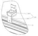
도 1과 도 2에 도시된 바와 같이, 본 발명의 실시예 1에 따른 일종의 위치고정 컨베이어 메커니즘은 컨베이어 장치(1)와 위치고정 장치(2)를 포함하며, 상기 컨베이어 장치(1)는 컨베이어부(12)를 포함하고, 상기 컨베이어부(12)는 물체를 지지하고 운반하는데에 사용하며; 상기 위치고정 장치(2)는 상기 컨베이어부(12)가 미리 지정된 위치로 운반한 물체를 고정하는데에 사용한다.As shown in Fig. 1 and Fig. 2, a kind of positioning conveyor mechanism according to Embodiment 1 of the present invention includes a conveyor device 1 and a
구체적으로는, 컨베이어 장치(1)는 생산라인에서 조립라인 작업에 사용하는 컨베이어 플레이트 체인 또는 벨트일 수 있고, 단일한 공정 생산 작업에 사용하는 물체 컨베이어일 수도 있으며, 그 운반 방향은 수평 또는 경사 방향이 될 수 있고, 컨베이어 장치는 지지대(11)가 포함되고, 지지대(11)는 지지 수요에 따라 강재를 리벳 연결, 나사 연결 또는 용접 연결하여 제작하는 것과 같이 구체적으로 설정할 수 있으며, 지지대(11)는 운반 길이에 따라 구체적으로 설치할 수 있고, 지지대(11)는 일체형 구조도 될 수 있고, 예를 들면 다수를 병렬로 배열하여 같이 연결한 지지대(11)과 같이 분리형 구조도 될 수 있다. 여기서, 바람지하게는, 본 실시예에서는 상기 지지대(11)는 컨베이어부(12)를 지지한다.Specifically, the conveyor apparatus 1 may be a conveyor plate chain or a belt used for assembly line work in a production line, or may be an object conveyor used for a single process production work, and the conveying direction may be a horizontal or inclined direction. It may be, the conveyor apparatus includes a
컨베이어부(12)는 수평인 컨베이어 벨트 또는 컨베이어 체인 플레이트일 수 있고, 경사진 컨베이어 벨트 또는 컨베이어 체인 플레이트일 수도 있다. 이때 컨베이어 벨트 구조에 맞춘 컨베이어부(12)는 구체적인 생산 수요에 따라, 컨베이어 벨트의 병행 수량과 각 벨트의 폭 등을 선택할 수 있다. 마찬가지로 체인 플레이트 구조에 맞춘 컨베이어부(12)도 생산 수요에 따라 체인 플레이트의 병행 수량과 각 체인 플레이트의 폭을 선택할 수 있다. 또한, 컨베이어부(12)는 위치고정 컨베이어의 일부일 수 있고, 서보 모터를 통해 제어할 수 있으며, 위치센서를 통해 위치 측정과 피드백을 할 수도 있고, 더 나아가 연속적인 일정 거리 운반을 실현할 수 있다.
즉, 컨베이어부(12)는 물체가 매번 동일한 거리를 운행하도록 할 수도 있고, 다른 거리를 운행하도록 할 수도 있으며, 해당 운행거리는 생산을 제어하는 메인 기기에서 제어할 수 있다. 컨베이어부(12)의 운행 속도는 실제 생산 수요에 따라 구체적으로 설정하며, 컨베이어부(12)의 표면은 운반하는 물체의 구조적 특징에 따라, 예를 들면 미끄럼방지 재료 층을 설치하는 것과 같은 표면 처리를 할 수도 있다. 여기서, 바람직하게는, 본 실시예에서는 수평인 컨베이어 벨트를 컨베이어부(12)로 하고 지지대(11)에 설치한다.That is, the
위치고정 장치(2)는 클램핑하고 위치를 고정할 수 있는 장치이며, 물체의 일 방향을 고정할 수 있고, 물체의 2개 방향을 고정할 수도 있다. 예를 들면, 물체의 운반 방향으로 고정할 수도 있고, 운반 방향으로 고정하는 동시에 상기 운반 방향에 수직인 방향으로도 고정할 수 있으며, 위치고정 장치의 구체적인 위치고정 및 클램핑 메커니즘은 구동장치로 구동하는 슬라이딩식 클램핑 장치일 수 있고, 구동장치로 구동하는 회전식 클램핑 장치일 수도 있으며, 단지 물체를 정확히 고정할 수만 있으면 된다. 여기서, 예를 들면 컨베이어 장치(1)의 지지대(11)에 설치되는것과 같이 위치고정 장치(2)를 컨베이어 장치(1)에 설치할 수 있고, 또는 위치고정 장치(2)와 컨베이어 장치(1)는 분리될 수도 있는데, 예를 들면, 위치고정 장치(2)는 컨베이어 장치(2)의 상방에 설치될 수 있고, 물체를 고정할 필요가 있을 때, 위치고정 장치(2)는 물체를 클램핑하여 고정할 수 있는 위치까지 운반할 수만 있으면 된다.The
본 발명에 따른 기술적 방안에서, 위치고정 컨베이어 메커니즘에 위치고정 장치를 추가로 설치하여, 컨베이어 장치가 미리 지정된 위치로 물체를 운반한 후, 위치고정 장치가 물체를 고정시킬 수 있어, 물체가 정확한 위치에 있게 된다. 이렇게 하면 물체에 대해 후속 공정인 조립, 가공 또는 공법처리 등을 진행할 때, 위치고정 컨베이어 메커니즘에서 물체가 있는 위치를 정확하게 찾을 수 있으며, 나아가 정밀한 자동화 생산을 편리하게 실현할 수 있다. 예를 들어, 본 발명에 따른 위치고정 컨베이어 메커니즘을 사용하여 고효율 헤테로 접합 전지 생산 과정의 PVD 설비 제조공정을 진행할 때, 로딩 플레이트를 지정된 위치로 운반하는 동시에, 위치고정 장치를 통해 로딩 플레이트를 정확히 고정하고, 나아가 뒤에 이어지는 웨이퍼를 놓는 작업을 더욱 정밀하게 하여, 생산 설비의 가동률을 낮추고 생산 효율을 높이며, 불량률을 낮출 수 있다.In the technical solution according to the present invention, after the positioning device is additionally installed in the positioning conveyor mechanism, and the conveyor device carries the object to a predetermined position, the positioning device can fix the object so that the object is positioned correctly. Will be in. In this way, when the assembly, processing, or process of the object, such as subsequent processes, can be precisely located where the object is located on the fixed position conveyor mechanism, precise automated production can be easily realized. For example, during the manufacturing process of PVD equipment in the production of high efficiency heterojunction cells using the positioning conveyor mechanism according to the present invention, the loading plate is transported to the designated position, and the loading plate is accurately fixed by the positioning device. In addition, it is possible to more precisely place the subsequent wafer to lower the operation rate of the production equipment, increase the production efficiency, and lower the defective rate.
도 1과 도 2에 도시된 바와 같이, 구체적인 실시예에서, 상기 위치고정 장치(2)는 제1 위치고정 클램핑부(21), 제2 위치고정 클램핑부(22), 구동장치가 포함되며; 상기 제1 위치고정 클램핑부(21)를 사용하여 물체를 제1 방향 상의 위치에 고정하고, 상기 제2 클램핑부(22)를 사용하여 물체를 제2 방향 상의 위치에 고정하며, 상기 구동장치를 사용하여 상기 제1 위치고정 클램핑부(21)와 제2 위치고정 클램핑부(22)를 구동하여 클램핑 동작을 실행한다. 여기서, 상기 제1 방향과 상기 컨베이어부(12)의 운반 방향은 서로 같고, 상기 제2 방향과 상기 제1 방향은 수직이다.1 and 2, in a specific embodiment, the
구체적으로는, 위치고정 장치(2)는 2개의 클램핑 방향이 수직인 제1 위치고정 클램핑부(21)와 제2 위치고정 클램핑부(22)로 구성되며, 제1 위치고정 클램핑부(21)는 구동장치로 제어되어 위치고정 및 클램핑 동작을 실현하는 어떠한 구조도 될 수 있고, 예를 들면 구동장치로 제어되는 2개의 클램핑 부품으로서, 구동장치를 통해 마주하여 슬라이딩할 수 있고, 나아가 수평 컨베이어부(12) 상의 물체를 운반 방향으로 클램핑하여 고정할 수 있으며, 마찬가지로 제2 위치고정 클램핑부(22)는 제1 위치고정 클램핑부(21)를 참고하여 설치할 수 있으나, 제2 위치고정 클램핑부(22)는 제2 방향에서 물체를 클램핑하고 고정해야 하며, 여기서, 제2 방향은 운반 방향에 수직이고, 제2 방향과 컨베이어부(12)가 위치한 평면이 평행하며, 나아가 제1 위치고정 클램핑부(21)와 제2 위치고정 클램핑부(22)를 통해 물체를 정확히 미리 설정된 위치에 고정할 수 있다. 즉 컨베이어부(12)가 물체를 운반해야 할 미리 설정된 위치, 예를 들면 컨베이어부가 수평 운반을 할 때, 제1 방향과 제2 방향은 동일한 수평면에 위치한다. 구동장치의 수량은 위치고정 장치(2)의 수량에 따라 설치하거나 제1 위치고정 클램핑부(21), 제2 위치고정 클램핑부(22)의 수량에 따라 설치할 수 있고, 구동장치는 클램핑부의 왕복운동을 구동할 수 있는 장치로서, 예를 들면 전동 실린더, 에어 실린더, 유압 실린더 또는 구동모터 등이 될 수 있다.Specifically, the
도 1과 도 2에 도시된 바와 같이, 구체적인 실시예에서, 상기 제1 위치고정 클램핑부(21)는 제1 위치고정 클램핑 개체(211)와 제2 위치고정 클램핑 개체(212)를 포함하며, 상기 제1 위치고정 클램핑 개체(211)와 상기 제2 위치고정 클램핑 개체(212)가 물체를 클램핑할 때, 마주하여 살치된다. 상기 제2 위치고정 클램핑부(22)는 제3 위치고정 클램핑 개체(221)와 제4 위치고정 클램핑 개체(222)가 포함되고, 상기 제3 위치고정 클램핑 개체(221)와 상기 제4 위치고정 클램핑 개체(222)가 상기 물체를 클램핑할 때 마주하여 살치된다.As shown in FIGS. 1 and 2, in a specific embodiment, the first
구체적으로는, 제1 위치고정 클램핑부(21)는 컨베이어부(12) 상의 물체를 운반 방향으로 위치시키는 클램핑 장치이며, 2개의 상응하게 설치되는 클램핑 개체 또는 회전한 후 물체의 양단과 상응하게 클램핑할 수 있는 클램핑 개체를 포함할 수 있다. 마찬가지로, 제2 위치고정 클램핑부(22)는 컨베이어부(12) 상의 물체를 제2 방향으로 위치시키는 클램핑 장치로서, 역시 마주하여 설치되는 2개의 클램핑 개체 또는 회전한 후 마주하여 물체의 양단을 클램핑할 수 있는 클램핑 개체가 포함될 수 있다.Specifically, the first fixed
도 1에 도시된 바와 같이, 구체적인 실시예에서, 위치고정 컨베이어 메커니즘은 마주하여 설치되는 지지대(11)도 포함되며, 상기 위치고정 장치(2)는 상기 지지대(11)에 설치된다.As shown in FIG. 1, in a specific embodiment, the positioning conveyor mechanism also includes a
구체적으로, 지지대(11)는 컨베이어 장치(1)를 지지할 수 있고, 위치고정 장치(2)를 고정할 수 있는, 예를 들면 강재를 용접하여 만든 지지체, 나사로 연결되어 지지하는 지지체 등 어떠한 형식의 지지체도 될 수 있다.Specifically, the
도 1과 도 2에 도시된 바와 같이, 더 나아가, 상기 위치고정 장치(2)는 다수의 세트로 구성되어, 각 세트의 위치고정 장치(2)에 적어도 1개의 제1 위치고정 클램핑부(21)와 적어도 1개의 제2 위치고정 클램핑부(22)가 포함되고, 즉 위치고정 장치(2)에 다수의 상기 제1 위치고정 클램핑부(21)와 다수의 상기 제2 위치고정 클램핑부(22)가 포함된다. 여기서, 다수의 상기 제1 위치고정 클램핑부(21)와 다수의 상기 제2 위치고정 클램핑부(22)는 모두 상기 제1 방향을 따라 간격을 두고 상기 지지대(11)에 설치된다.As shown in FIGS. 1 and 2, furthermore, the
구체적으로, 컨베이어 장치(1)는 일정한 거리로 물체를 운반하는 장치일 수 있고, 즉 컨베이어부(12)는 한 스텝씩 운동한 후 정지할 수 있으며, 따라서 위치고정 장치(2)를 다수의 세트로 설치하고, 세트의 개수는 컨베이어 장치(1)가 일정한 거리로 물체를 운반하는 스텝의 개수와 동일하며, 각각의 위치고정 장치(2)의 세트는 컨베이어부(12)가 물체를 운반할 때 매번 정지하는 위치에 대응하여 설치되어야 하고, 여기에서 상기 위치고정 운반 스텝이란 컨베이어 장치(1)가 물체를 운반하는 일정한 하나의 운반거리에 대응하는 하나의 스텝을 가리키며, 제1 위치고정 클램핑부(21)와 제2 위치고정 클램핑부(22)는 모두 컨베이어 장치(1)의 지지대(11)에 설치해야 하고, 양자의 구조가 서로 같은 것이 가장 바람직하며, 물체를 클램핑할 때의 구체적인 수요에 따라 구체적으로 설치할 수도 있다.Specifically, the conveyor apparatus 1 may be a device for carrying an object at a predetermined distance, that is, the
도 1과 도 2에 도시된 바와 같이, 구체적인 실시예에서, 상기 제1 위치고정 클램핑부(21)는 제1 위치고정 클램핑 개체(211)와 제2 위치고정 클램핑 개체(212)가 포함되며, 상기 제1 위치고정 클램핑 개체(211)와 상기 제2 위치고정 클램핑 개체(212)가 마주하여 설치되고, 상기 제1 위치고정 클램핑 개체(211)와 상기 제2 위치고정 클램핑 개체(212) 사이의 거리와, 상기 물체의 상기 제1 방향 길이가 서로 대응한다. 상기 제2 위치고정 클램핑부(22)는 제3 위치고정 클램핑 개체(221)와 제4 위치고정 클램핑 개체(222)가 포함되고, 상기 제3 위치고정 클램핑 개체(221)와 상기 제4 위치고정 클램핑 개체(222)가 마주하여 설치되며, 상기 제3 위치고정 클램핑 개체(221)와 상기 제4 위치고정 클램핑 개체(222) 사이의 거리와, 상기 물체의 상기 제2 방향 길이와 서로 대응한다.1 and 2, in a specific embodiment, the first
구체적으로, 제1 위치고정 클램핑부(21)는 컨베이어부(12)에 있는 물체의 운반 방향으로 위치를 정하는 클램핑 장치로서, 마주보는 위치의 클램핑 개체 2개를 포함할 수 있고, 즉 제1 위치고정 클램핑 개체(211)와 제2 위치고정 클램핑 개체(212)가 마주하는 운동을 통해, 물체를 운반 방향으로 클램핑하고 위치를 고정할 수 있다. 제1 위치고정 클램핑 개체(211)와 제2 위치고정 클램핑 개체(212)의 운동 거리는 실제 수요에 따라 설정할 수 있으나, 제1 위치고정 클램핑 개체(211)와 제2 위치고정 클램핑 개체(212)의 운동 거리가 최소가 되어 작업 효율을 향상시키기 위해, 제1 위치고정 클램핑 개체(211)와 제2 위치고정 클램핑 개체(212) 사이의 거리는 물체의 운반 방향 거리와 서로 대응하는 것이 가장 바람직하며, 제1 위치고정 클램핑 개체(211)와 제2 위치고정 클램핑 개체(212)는 마주하여 슬라이딩하면서 물체를 클램핑할 수도 있고, 예를 들면 제1 위치고정 클램핑 개체(211)의 일단과 구동장치가 연결되어, 회전운동 방식을 통해, 양자가 회전한 후에 물체를 클램핑하고 위치를 고정할 수도 있다. 구동장치는 제1 위치고정 클램핑 개체(211)의 회전운동을 유발하여, 제1 위치고정 클램핑 개체(211)의 다른 일단이 물체의 한쪽을 누르고 있도록 하며, 마찬가지로 제2 위치고정 클램핑 개체(212)의 설치 방식도 제1 위치고정 클램핑 개체(211)의 설치 방식과 동일하여, 제2 위치고정 클램핑 개체(212)의 회전운동을 통해, 그 일단이 물체의 다른 한쪽을 누르고 있을 수 있고, 나아가 클램핑과 위치 고정을 실현한다. 제2 위치고정 클램핑부(22)와 제1 위치고정 클램핑부(21)의 구조, 그리고 설치 방식은 서로 같을 수 있으나, 제2 위치고정 클램핑부(22)의 제3 위치고정 클램핑 개체(221)와 제4 위치고정 클램핑 개체(222) 사이의 거리는 물체의 제2 방향 길이와 서로 대응되어야 한다. 또한, 제3 위치고정 클램핑 개체(221)와 제4 위치고정 클램핑 개체(222)가 물체의 위치를 고정하고 클램핑하는 방식은 제1 위치고정 클램핑 개체(211)와 제2 위치고정 클램핑 개체(212)를 참고하여 설치할 수 있고, 여기에서는 더 자세히 설명하지 않는다. Specifically, the first
또한, 각각의 위치고정 장치(2) 세트에서 제1 위치고정 클램핑부(21)의 제1 위치고정 클램핑 개체(211) 수량은 1개일 수도 있고, 예를 들어 2개 등 다수일 수도 있으며, 클램핑하는 물체의 제2 방향 길이에 따라 정할 수 있고, 제1 위치고정 클램핑 개체(211)는 수평 컨베이어부(12)의 비어 있는 위치에 설치하는 것이 가장 바람직하다. 마찬가지로, 제2 위치고정 클램핑 개체(212)의 수량도 1개 또는 예를 들어 2개 등 다수일 수 있으며, 또한 각각의 제2 위치고정 클램핑 개체(212)가 모두 한 세트에 있는 제1 위치고정 클램핑 개체(211)와 마주할 수 있다.In addition, the number of the first
더 나아가, 다수의 위치고정 장치(2)세트에 있는 각 세트의 제1 위치고정 클램핑부(21)와 제2 위치고정 클램핑부(22)의 분포로 인해, 컨베이어 장치(1)의 특징적인 일정한 운반거리 스텝을 만족시켜야 하고, 또한 제1 위치고정 클램핑부(21)는 컨베이어부(12)의 운반 방향에 위치하며, 즉 서로 인접한 2개의 상기 제1 위치고정 클램핑 개체(211) 사이의 거리가, 상기 일정한 운반거리 스텝에 대응하는 거리와 같아야 한다. 동시에, 서로 인접한 2개의 상기 제2 위치고정 클램핑 개체(212) 사이의 거리도 상기 일정한 운반거리 스텝에 대응하는 거리와 같아야 한다. 그러나 제2 위치고정 클램핑부(22)가 컨베이어부(12)의 운반 방향에 수직인 위치, 즉 컨베이어부(12)의 양쪽에 있기 때문에, 제2 위치고정 클램핑부(22)의 수량은 상기 제1 위치고정 클램핑부(21)의 수량보다 적거나 같을 수 있다. 여기서, 상기 제2 위치고정 클램핑부(22) 하나를 하나 또는 다수의 서로 인접한 상기 제1 위치고정 클램핑부(21)에 각각 적용하여 상기 위치고정 장치(2) 한 세트를 구성할 수 있으며, 이렇게 서로 인접한 2개의 상기 제3 위치고정 클램핑 개체(221) 사이의 거리가, 일정한 운반거리 스텝에 대응하는 거리와 같거나, 상기 물체의 제1 방향 길이의 1/5내지 1/2과 같을 수 있다. 서로 인접한 2개의 상기 제4 위치고정 클램핑 개체(222) 사이의 거리는 일정한 운반거리 스텝에 대응하는 거리와 같거나, 상기 물체의 상기 제1 방향 길이의 1/5 내지 1/2과 같을 수 있다.Furthermore, due to the distribution of the first
도 1과 도 2에 도시된 바와 같이, 구체적인 실시예에서, 각각의 제1 위치고정 클램핑부(21)에는 대응하는 하나의 구동장치(도면에는 미제시)를 설치해야 하며, 구동장치는 제1 구동장치와 제2 구동장치를 포함하는 것이 가장 바람직하다. 여기서, 상기 제1 구동장치의 수량은 상기 제1 위치고정 클램핑 개체(211)의 수량과 같고, 상기 제1 위치고정 클램핑 개체(211)를 구동하는데 사용하며, 상기 제2 구동장치의 수량은 상기 제2 위치고정 클램핑 개체(212)의 수량과 같고, 상기 제2 위치고정 클램핑 개체(212)를 구동하는데 사용한다.As shown in Fig. 1 and Fig. 2, in a specific embodiment, each of the first
도 1내지 도 4에 도시된 바와 같이, 더 나아가, 상기 제1 위치고정 클램핑 개체(211)는 제1 슬라이딩 블록(2111)과 제2 슬라이딩 블록(2112)이 포함되며, 상기 제1 슬라이딩 블록(2111)과 상기 지지대(11)는 상기 제1 방향을 따라 슬라이딩 연결되고, 상기 제2 슬라이딩 블록(2112)과 상기 제1 슬라이딩 블록(2111)은 수직으로 슬라이딩 연결된다. 상기 제1 구동장치에는 제1 방향 구동장치와 수직방향 구동장치가 포함되며, 상기 제1 방향 구동장치와 상기 제1 슬라이딩 블록(2111)이 연결되어, 상기 제1 슬라이딩 블록(2111)을 구동하여, 상기 제1 방향을 따라 왕복운동을 하도록 하며, 상기 수직방향 구동장치와 상기 제2 슬라이딩 블록(2112)이 연결되어, 상기 제2 슬라이딩 블록(2112)을 구동하여, 수직방향으로 왕복운동을 하도록 한다. 여기서, 상기 제2 위치고정 클램핑 개체(212)와 상기 제1 위치고정 클램핑 개체(211)의 구조가 같고, 상기 제1 구동장치와의 연결 구조도 같다.As shown in FIGS. 1 to 4, the first
또한, 제1 위치고정 클램핑 개체(211)와 제2 위치고정 클램핑 개체(212)를 컨베이어부(12)에 설치하여, 운반하는 물체의 표면 하방에 사용함으로써, 컨베이어부(12)가 물체를 일정한 거리로 한 스텝 운반할 때, 대응하는 위치의 제1 위치고정 클램핑부(21)를 사용하여, 컨베이어부(12) 상의 물체가 제1 방향에서 도달하는 위치를 클램핑하고 고정해야 할 때, 수직 방향의 구동장치 2개가 각각 제1 위치고정 클램핑 개체(211)와 제2 위치고정 클램핑 개체(212)의 제2 슬라이딩 블록(2112) 2개를 구동하여, 제2 슬라이딩 블록(2112) 2개가 위로 운동하도록 하고, 물체와 같은 높이의 위치까지 운동하면, 제1 방향 구동장치 2개가 각각 제1 위치고정 클램핑 개체(211)와 제2 위치고정 클램핑 개체(212)의 제1 슬라이딩 블록(2111)을 각각 구동하여, 양자가 동시에, 그리고 마주하여 운동하도록 하며, 최종적으로 물체가 클램핑되고 물체가 일정한 거리를 운동한 후 제1 방향으로 위치가 고정되도록 한다.In addition, the first
더 나아가, 제3 위치고정 클램핑 개체(221)와 제4 위치고정 클램핑 개체(222)의 설치 방식은 제1 위치고정 클램핑 개체(211)를 참고할 수 있으며, 즉 상기 제3 위치고정 클램핑 개체(221)에 제3 슬라이딩 블록(2211)과 제4 슬라이딩 블록(2212)을 포함할 수 있고, 상기 제3 슬라이딩 블록(2211)과 컨베이어 장치(1)의 지지대(11)는 상기 제2 방향을 따라 슬라이딩 연결되며, 상기 제4 슬라이딩 블록(2212)과 상기 제3 슬라이딩 블록(2211)은 수직으로 슬라이딩 연결된다. 상기 제2 구동장치는 제2 방향 구동장치와 수직방향 구동장치를 포함하며, 상기 제2 방향 구동장치와 상기 제3 슬라이딩 블록(2211)이 연결되어, 상기 제3 슬라이딩 블록(2211)을 구동하여, 상기 제2 방향을 따라 왕복운동을 하도록 하고, 상기 수직방향 구동장치와 상기 제4 슬라이딩 블록(2212)이 연결되어, 상기 제4 슬라이딩 블록(2212)을 구동하여, 수직방향으로 왕복운동을 하도록 한다. 여기서, 상기 제4 위치고정 클램핑 개체(222)와 상기 제3 위치고정 클램핑 개체(221)의 구조가 같고, 상기 제2 구동장치와의 연결 구조도 같다.Furthermore, the installation method of the third
구체적으로는, 제3 위치고정 클램핑 개체(221)와 제4 위치고정 클램핑 개체(222)를 컨베이어부(12)의 양쪽, 즉 운반 방향에 수직인 양쪽에 설치하는 것이 가장 바람직하며, 이렇게 하면 컨베이어부(12)가 일정한 거리로 물체를 한 스텝 운반한 후, 대응하는 위치에 있는 제2 위치고정 클램핑부(22)로 위치고정 컨베이어부(12) 상의 물체를 제2 방향의 위치까지 운반할 때, 수직방향의 구동장치 2개가 각각 제3 위치고정 클램핑 개체(221)와 제4 위치고정 클램핑 개체(222)의 제4 슬라이딩 블록(2212) 2개를 각각 구동하여, 제4 슬라이딩 블록(2212) 2개가 위로 운동하도록 하며, 물체와 같은 높이의 위치까지 운동한 후, 제2 방향 구동장치 2개가 제3 위치고정 클램핑 개체(221)와 제4 위치고정 클램핑 개체(222)의 제3 슬라이딩 블록(2211) 2개를 각각 구동하여, 양자가 동시에, 그리고 마주하여 운동하도록 하여, 최종적으로 물체를 클램핑하고, 물체가 일정한 거리를 운동한 후 제2 방향으로 위치가 고정되도록 한다.Specifically, it is most preferable to install the third
또한, 제3 위치고정 클램핑 개체(221)와 제4 위치고정 클램핑 개체(222)는 물체의 운동방향 양쪽에 클램핑하므로, 제3 위치고정 클램핑 개체(221)와 제4 위치고정 클램핑 개체(222)는 대응하는 물체의 일정한 운반거리에 맞춰 설정할 필요가 없으며, 단지 제2 방향으로 물체를 클램핑하면 되므로 제3 위치고정 클램핑 개체(221)는 예를 들면 하나의 클램핑 플레이트, 클램핑 스트립 등 하나로 연결된 구조도 가능하며, 동시에 제4 위치고정 클램핑 개체(222)도 하나로 연결된 구조도 가능하고, 제3 위치고정 클램핑 개체(221)의 구조와 같을 수 있고, 길이가 비교적 긴 클램핑 플레이트 또는 클램핑 스트립으로 설치할 수 있으며, 이로써 물체가 컨베이어부(12) 상에서 일정한 거리로 하나의 스텝 또는 다수의 스텝을 운동해도, 모두 제3 위치고정 클램핑 개체(221)와 제4 위치고정 클램핑 개체(222)를 통해 클램핑할 수 있어, 물체의 운동 거리를 고려할 필요가 없으며, 단지 물체가 일정한 거리를 운동한 후에 제3 위치고정 클램핑 개체(221)와 제4 위치고정 클램핑 개체(222)가 물체의 위치를 고정하고 클램핑하기만 하면 된다. 이 때, 다수의 상기 제3 위치고정 클램핑 개체(221)가 같이 연결되고, 다수의 상기 제4 위치고정 클램핑 개체(222)가 같이 연결되며, 또한 각각이 상기 지지대(11)와 같이 제2 방향을 따라 슬라이딩 연결되고, 상기 제2 구동장치가 다수의 상기 제3 위치고정 클램핑 개체(221)를 구동하여, 상기 제2 방향을 따라 왕복운동을 하도록 하며, 상기 제2 구동장치는 다수의 상기 제4 위치고정 클램핑 개체(222)를 구동하여, 상기 제2 방향을 따라 왕복운동을 하도록 한다.In addition, since the third
구체적인 실시예에서, 상기 제2 슬라이딩 블록에 롤러 형태의 그리퍼를 설치하고, 상기 제4 슬라이딩 블록에 롤러 형태의 그리퍼를 설치한다.In a specific embodiment, a roller-type gripper is installed on the second sliding block, and a roller-type gripper is installed on the fourth sliding block.
구체적으로는, 제2 슬라이딩 블록과 제4 슬라이딩 블록은 모두 물체를 클램핑하고 위치를 고정할 때 물체와 직접 접촉하는 부품이므로, 양자를 롤러 형태로 설치하면 물체가 가장자리에 부딪혀 손상되는 것을 방지할 수 있을 뿐만 아니라, 클램핑하는 과정에서 가이드 역할도 하게 된다. 또한, 제2 슬라이딩 블록과 제 4 슬라이딩 블록이 물체를 클램핑할 때 물체를 손상시키지 않도록, 더 나아가 제2 슬라이딩 블록과 제4 슬라이딩 블록의 표면에 탄성고무 재료를 설치할 수도 있다.Specifically, since the second sliding block and the fourth sliding block are both parts that directly contact the object when clamping the object and fixing the position, installing the roller in both forms prevents the object from hitting the edge and being damaged. In addition, it also serves as a guide in the clamping process. In addition, an elastic rubber material may be provided on the surfaces of the second sliding block and the fourth sliding block so that the second sliding block and the fourth sliding block do not damage the object when clamping the object.
구체적인 실시예에서, 본 발명에 따른 위치고정 컨베이어 메커니즘은 상기 물체의 위치 정보를 측정하는 위치센서와 제어장치도 포함하며, 상기 제어장치는 상기 위치센서가 측정한 물체의 위치 정보와 상기 제어장치 안에 미리 저장된 제1 사전설정 위치 정보의 차이 값을 의거하여 상기 컨베이어 장치를 제어한다.In a specific embodiment, the position fixing conveyor mechanism according to the present invention also includes a position sensor and a control device for measuring the position information of the object, the control device is located in the control device and the position information of the object measured by the position sensor The conveyor apparatus is controlled based on a difference value of pre-stored first preset position information.
구체적으로, 위치센서는 상기 제1 방향을 따라 간격을 두고 지지대 위에 설치할 수 있고, 각각의 위치 제어기를 물체가 매번 일정한 거리 스텝 중에 정지해야 할 위치, 즉 물체를 운반할 사전설정 위치에 설치한다. 제어장치는 위치고정 컨베이어 메커니즘 외부의 제어용 컴퓨터 또는 마이크로 컨트롤러에 설치하거나 위치고정 컨베이어 메커니즘 위의 메인 제어기기에 설치할 수도 있고, 생산 라인에서 생산을 제어하는 제어 시스템이 될 수도 있다.Specifically, the position sensor may be installed on the support at intervals along the first direction, and each position controller is installed at a position where the object should stop during a certain distance step each time, that is, a preset position to carry the object. The control device may be installed in a control computer or microcontroller outside the fixed conveyor mechanism or in the main controller above the fixed conveyor mechanism, or may be a control system for controlling production on a production line.
실시예 2Example 2
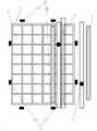
본 발명에 따른 실시예 2는 위치고정 컨베이어 메커니즘이 포함된 일종의 위치고정 컨베이어 생산 시스템을 제공하며, 도 1과 도 2에 도시된 바와 같이, 상기 위치고정 컨베이어 메커니즘은 컨베이어 장치(1)와 위치고정 장치(2)가 포함되고, 상기 컨베이어 장치(1)는 컨베이어부(12)가 포함되고, 상기 컨베이어부(12)를 이용하여 물체를 지지하고 운반하게 된다. 상기 위치고정 장치(2)를 사용하여 상기 컨베이어부(12)가 미리 지정된 위치로 운반한 물체를 고정하게 된다. 도 5에 도시된 바와 같이, 위치고정 컨베이어 생산 시스템에는 조립대기 부품 운반 장치(3)가 포함되며, 상기 조립대기 부품 운반 장치(3)는 상기 위치고정 컨베이어 메커니즘의 컨베이어부(12) 상방에 설치하여, 상기 조립대기 부품을 운반하는데 사용한다. 상기 물체(5)에는 제2 사전설정 위치가 설치되어, 상기 조립대기 부품을 지지하는데 사용하며, 제1 위치센서(4)를 사용하여 상기 조립대기 부품 운반장치(3)의 조립대기 부품의 위치 정보를 측정하게 된다. 제2 위치센서 장치(6)를 사용하여 상기 제2 사전설정 위치 정보, 즉 상기 컨베이어부(12)의 물체(5)의 조립대기 부품 사전설정 위치를 측정하게 된다. 실행장치(도면에는 미제시)는 상기 제1 위치센서 장치(4)와 제2 위치센서 장치(6)가 발송하는 위치 신호를 수신하여, 상기 조립대기 부품을 상기 물체(5)의 제2 사전설정 위치, 즉 조립대기 부품 장착 위치에 놓게 된다.
구체적으로는, 본 실시예 2에서 상기 위치고정 컨베이어 메커니즘은 상기 실시예 1에 제공된 위치고정 컨베이어 메커니즘을 직접 사용할 수 있고, 구체적인 실시 구조는 상기 실시예 1에 기술된 관련 내용을 참고할 수 있으며, 여기에서는 자세히 설명하지 않는다. 여기서, 제1 위치센서 장치와 제2 위치센서 장치는 모두 시각 센서일 수 있다.Specifically, in the second embodiment, the positioning conveyor mechanism may directly use the positioning conveyor mechanism provided in the first embodiment, and specific embodiments may refer to the related contents described in the first embodiment. Does not go into detail. Here, both the first position sensor device and the second position sensor device may be visual sensors.
도 5에 도시된 바와 같이, 여기서, 위치고정 컨베이어 메커니즘은 일정한 위치로 물체를 운반할 수 있으며, 일정한 위치로 운반된 물체를 고정시킬 수 있고, 나아가 물체를 정확한 위치에 유지할 수 있다. 조립대기 부품 운반장치(3)는 위치고정 컨베이어 메커니즘의 컨베이어 장치(1)와 동일한 장치일 수 있으며, 또한 조립대기 부품 운반장치(3)는 물품을 평면으로 운반하는 컨베이어 장치로 하여, 실행장치가 조립대기 부품을 편리하게 집도록 하는 것이 가장 바람직하다. 제1 위치센서 장치(4)와 제2 위치센서 장치(6)의 수량은 컨베이어 장치(1)에서 조립대기 부품이 차지하는 면적을 기준으로 할 수 있으며, 위치고정 컨베이어 메커니즘에서 물체(5)가 차지하는 면적을 기준으로 정할 수도 있고, 제1 위치센서 장치(4)와 제2 위치센서 장치(6)를 사용하여 조립대기 부품 운반장치(3)에서 조립대기 부품의 위치를 측정하며, 상기 컨베이어부(12)에서 물체의 조립대기 부품의 장착 위치를 측정하고, 동시에 측정된 결과를 제어센터, 제어기로 전송하거나 직접 실행장치로 전송한다.As shown in FIG. 5, here, the positioning conveyor mechanism can carry the object to a fixed position, can fix the carried object to a fixed position, and further keep the object in the correct position. The assembly-waiting
실행장치는 공업에서 흔히 사용하는 다축 로봇이 될 수 있고, 이를 위치고정 컨베이어 생산 시스템의 제어장치로 제어할 수도 있으며, 예를 들면 마이크로 컨트롤러와 같이, 실행장치 자체에 제어장치를 설치할 수도 있다. 실행장치는 영상센서 장치에서 나온 측정 신호를 직접 수신할 수 있고, 위치센서 장치에서 나온 측정 신호를 제어기로 처리한 후에 수신할 수도 있다. 또한, 측정 신호의 정보에 따라 조립대기 부품 운반장치에서 조립대기 부품을 집은 후, 조립대기 부품을 수평 컨베이어부 상의 물체에 장착하고, 나아가 조립하고 놓는 작업을 완성한다.The execution device may be a multi-axis robot commonly used in the industry, and may be controlled by a control device of a positioning conveyor production system, and a control device may be installed in the execution device itself, for example, a microcontroller. The execution device may directly receive the measurement signal from the image sensor device, and may receive the measurement signal from the position sensor device after processing it with the controller. In addition, after picking up the assembly standby component in the assembly standby component transporter in accordance with the information of the measurement signal, the assembly standby component is mounted on the object on the horizontal conveyor unit, and further completes the work of assembling and laying.
본 발명의 기술적 방안에서, 위치고정 컨베이어 메커니즘에 위치고정 장치를 추가로 설치하여, 컨베이어 장치가 물체를 미리 지정된 위치로 운반한 후, 위치고정 장치가 물체를 고정할 수 있어, 물체가 정확한 위치에 놓이게 된다. 이렇게 하면 물체에 대해 후속 공정인 조립, 가공, 공법처리를 수행할 때, 위치고정 컨베이어 메커니즘에서 물체의 정확한 위치를 찾을 수 있고, 나아가 정밀한 자동화 생산을 쉽게 실현할 수 있다. 예를 들어 본 발명에 따른 위치고정 컨베이어 메커니즘을 이용하여 고효율 헤테로 접합 전지 생산 과정의 PVD 설비 제조공정을 진행할 때, 로딩 플레이트를 지정된 위치로 운반하는 동시에, 위치고정 장치를 통해 로딩 플레이트를 정확히 고정시킬 수 있고, 나아가 뒤에 이어지는 웨이퍼를 놓는 작업이 더욱 더 정밀해져서, 생산설비의 가동률을 낮추고 생산효율을 높이며, 불량률을 줄일 수 있다.In the technical solution of the present invention, by additionally installing a positioning device in the positioning conveyor mechanism, after the conveyor device carries the object to a predetermined position, the positioning device can fix the object, so that the object is in the correct position. Will be placed. This makes it possible to find the exact position of the object on a fixed-position conveyor mechanism when performing the subsequent processes of assembly, processing and processing on the object, and furthermore, it is easy to realize precise automated production. For example, when the PVD facility manufacturing process of the production of high efficiency heterojunction cells is carried out using the positioning conveyor mechanism according to the present invention, the loading plate is transported to the designated position, and the loading plate is accurately fixed by the positioning device. In addition, the subsequent laying of wafers can be made more precise, resulting in lower utilization of production equipment, higher production efficiency, and reduced failure rates.
도 5에 도시된 바와 같이, 구체적인 실시예에서, 상기 조립대기 부품 운반장치(3)의 운반 방향과 컨베이어부(12)의 운반 방향은 서로 수직이다. 상기 실행장치의 수량은 2개로서, 2개의 상기 실행장치의 상대적인 위치는 상기 위치고정 컨베이어 메커니즘의 컨베이어 장치의 양쪽이다.As shown in FIG. 5, in a specific embodiment, the conveying direction of the assembly-waiting
구체적으로는, 조립대기 부품 운반장치를 위치고정 컨베이어 메커니즘의 컨베이어 장치 상방에 설치하기 때문에, 조립대기 부품을 컨베이어부의 물체에 편리하게 장착하기 위해서는 조립대기 부품 운반장치가 컨베이어 장치의 상방 공간을 최대한 적게 차지하는 것이 가장 바람직하다. 그러므로 조립대기 부품 운반장치의 운반 방향과 상기 컨베이어부의 운반 방향이 수직인 것이 가장 바람직하다. 또한, 실행장치의 수량은 단지 장착 생산 작업에 충분하면 되며, 너무 많으면 낭비가 발생하고 생산 비용이 높아진다. 그러므로 2개의 실행장치를 설치하고, 2개의 실행장치를 마주하게 설치하는 것이 가장 바람직하다. Specifically, since the assembly waiting part conveying device is installed above the conveyor device of the position fixing conveyor mechanism, the assembly waiting part conveying device uses as little as possible the upper space of the conveyor device in order to conveniently mount the assembly waiting part on the object of the conveyor unit. Most preferred. Therefore, it is most preferable that the conveying direction of the assembly-waiting part conveying device and the conveying direction of the conveyor unit are vertical. In addition, the quantity of executor only needs to be sufficient for the mounted production operation, too much waste and high production cost. Therefore, it is most preferable to install two execution devices and to install two execution devices facing each other.
이상은 단지 본 발명의 가장 바람직한 실시예에 불과하며, 본 발명을 어떠한 형식으로도 제한하지 않고, 본 발명의 실질적인 기술을 근거로 이상의 실시예에 대해 행한 일체의 간단한 수정, 동등한 변화와 장식은 모두 본 발명의 기술적 방안의 범위에 속한다.The foregoing is merely the most preferred embodiment of the present invention, and does not limit the present invention to any form, and any simple modifications, equivalent changes, and decorations made to the above embodiments based on the actual technology of the present invention are all It belongs to the scope of the technical solution of this invention.
Claims (18)
Translated fromKorean상기 컨베이어부가 미리 지정된 위치로 운반한 물체를 고정하는 위치고정 장치;
를 포함하는 것을 특징으로 하는 위치고정 컨베이어 메커니즘.A conveyor device including a conveyor unit for supporting and carrying an object;
A position fixing device for fixing an object carried by the conveyor unit to a predetermined position;
Position fixed conveyor mechanism comprising a.
상기 위치고정 장치는 제1 위치고정 클램핑부, 제2 위치고정 클램핑부 및 구동장치가 포함되며;
상기 제1 위치고정 클램핑부는 물체를 제1 방향의 위치에 고정하는 역할을 하며, 상기 제2 위치고정 클램핑부는 물체를 제2 방향의 위치에 고정하는 역할을 하고, 상기 구동장치는 상기 제1 위치고정 클램핑부와 상기 제2 위치고정 클램핑부의 클램핑 동작을 구동하는 역할을 하고;
상기 제1 방향과 상기 컨베이어부의 운반 방향은 같으며, 상기 제2 방향과 상기 제1 방향은 서로 수직인 것을 특징으로 하는 위치고정 컨베이어 메커니즘.The method of claim 1,
The positioning device includes a first positioning clamping part, a second positioning clamping part and a driving device;
The first position fixing clamping portion serves to fix the object at a position in a first direction, and the second position fixing clamping portion serves to fix the object at a position in a second direction, and the driving device is at the first position. Serves to drive a clamping operation of the fixed clamping portion and the second fixed position clamping portion;
The first direction and the conveying direction of the conveyor portion is the same, and the second direction and the first direction is a fixed position conveyor mechanism, characterized in that perpendicular to each other.
상기 제1 위치고정 클램핑부는 제1 위치고정 클램핑 개체와 제2 위치고정 클램핑 개체가 포함되고;
상기 제1 위치고정 클램핑 개체와 상기 제2 위치고정 클램핑 개체는 상기 물체를 클램핑할 때 마주하여 설치되며;
상기 제2 위치고정 클램핑부는 제3 위치고정 클램핑 개체와 제4 위치고정 클램핑 개체가 포함되고;
상기 제3 위치고정 클램핑 개체와 상기 제4 위치고정 클램핑 개체는 상기 물체를 클램핑할 때 마주하여 설치되는 것을 특징으로 하는 위치고정 컨베이어 메커니즘.The method of claim 2,
The first position clamping portion includes a first position clamping entity and a second position clamping entity;
The first positioning clamping object and the second positioning clamping object are installed facing each other when clamping the object;
The second positioning clamping portion includes a third positioning clamping entity and a fourth positioning clamping entity;
And said third fixed clamping object and said fourth fixed clamping object are installed facing each other when clamping said object.
상기 위치고정 컨베이어 메커니즘은 상응하게 설치되는 지지대가 더 포함되고;
상기 위치고정 장치는 상기 지지대에 설치되는 것을 특징으로 하는 위치고정 컨베이어 메커니즘.The method of claim 2,
The positioning conveyor mechanism further includes a support that is correspondingly installed;
The positioning device is fixed to the conveyor mechanism, characterized in that installed on the support.
상기 위치고정 장치는 다수의 세트이며, 다수의 상기 제1 위치고정 클램핑부와 다수의 상기 제2 위치고정 클램핑부는 모두 상기 제1 방향을 따라, 상기 지지대에 간격을 두고 설치되는 것을 특징으로 하는 위치고정 컨베이어 메커니즘.The method of claim 4, wherein
The position fixing device is a plurality of sets, the plurality of the first position fixing clamping portion and the plurality of second position fixing clamping portion are all positioned along the first direction, spaced apart on the support Fixed conveyor mechanism.
상기 제1 위치고정 클램핑부는 제1 위치고정 클램핑 개체와 제2 위치고정 클램핑 개체가 포함되고;
상기 제1 위치고정 클램핑 개체와 상기 제2 위치고정 클램핑 개체는 마주하여 설치되며;
상기 제2 위치고정 클램핑부는 제3 위치고정 클램핑 개체와 제4 위치고정 클램핑 개체가 포함되고;
상기 제3 위치고정 클램핑 개체와 상기 제4 위치고정 클램핑 개체가 마주하여 설치되는 것을 특징으로 하는 위치고정 컨베이어 메커니즘.The method of claim 5,
The first position clamping portion includes a first position clamping entity and a second position clamping entity;
The first positioning clamping object and the second positioning clamping object are installed facing each other;
The second positioning clamping portion includes a third positioning clamping entity and a fourth positioning clamping entity;
And the third positioning clamping object and the fourth positioning clamping object are installed to face each other.
서로 인접한 2개의 상기 제1 위치고정 클램핑 개체 사이의 거리는 상기 컨베이어부가 매번 물체를 운반하는 거리와 같고;
서로 인접한 2개의 상기 제2 위치고정 클램핑 개체 사이의 거리는 상기 컨베이어부가 매번 물체를 운반하는 거리와 같은 것을 특징으로 하는 위치고정 컨베이어 메커니즘.The method of claim 6,
The distance between the two first positioning clamping objects adjacent to each other is equal to the distance that the conveyor carries each object;
And the distance between the two second positioning clamping objects adjacent to each other is equal to the distance that the conveyor carries the object each time.
서로 인접한 2개의 상기 제1 위치고정 클램핑 개체 사이의 거리는 상기 컨베이어부가 매번 물체를 운반하는 거리와 같은 것을 특징으로 하는 위치고정 컨베이어 메커니즘.The method of claim 6,
And the distance between the two first positioning clamping objects adjacent to each other is equal to the distance that the conveyor carries the object each time.
서로 인접한 2개의 상기 제2 위치고정 클램핑 개체 사이의 거리는 상기 컨베이어부가 매번 물체를 운반하는 거리와 같은 것을 특징으로 하는 위치고정 컨베이어 메커니즘.The method of claim 6,
And the distance between the two second positioning clamping objects adjacent to each other is equal to the distance that the conveyor carries the object each time.
상기 제2 위치고정 클램핑부의 수량은 상기 제1 위치고정 클램핑부의 수량보다 적거나 같으며;
하나의 상기 제2 위치고정 클램핑부는 각각 하나 또는 다수의 서로 인접한 상기 제1 위치고정 클램핑부와 같이 한 세트의 상기 위치고정 장치를 구성하는 것을 특징으로 하는 위치고정 컨베이어 메커니즘.The method of claim 5,
The quantity of the second positioning clamping portions is less than or equal to the quantity of the first positioning clamping portions;
And said one second positioning clamping portion constitutes a set of said positioning apparatuses, such as one or a plurality of adjacent first positioning clamping portions, respectively.
상기 구동장치는 제1 구동장치와 제2 구동장치가 포함되며;
상기 제1 구동장치는 상기 제1 위치고정 클램핑 개체를 구동하고, 상기 제2 구동장치는 상기 제2 위치고정 클램핑 개체를 구동하는 것을 특징으로 하는 위치고정 컨베이어 메커니즘.The method of claim 6,
The driving device includes a first driving device and a second driving device;
And said first drive drives said first fixed clamping object, and said second drive drives said second fixed clamping object.
상기 제1 위치고정 클램핑 개체는 제1 슬라이딩 블록과 제2 슬라이딩 블록이 포함되며, 상기 제1 슬라이딩 블록과 상기 지지대는 상기 제1 방향을 따라 슬라이딩 연결되고, 상기 제2 슬라이딩 블록과 상기 제1 슬라이딩 블록은 수직으로 슬라이딩 연결되며;
상기 제1 구동장치는 제1 방향 구동장치와 수직방향 구동장치가 포함되며, 상기 제1 방향 구동장치는 상기 제1 슬라이딩 블록과 연결되어 상기 제1 슬라이딩 블록을 구동하여 상기 제1 방향을 따라 왕복운동을 하도록 하고;
상기 제2 위치고정 클램핑 개체와 상기 제1 위치고정 클램핑 개체의 구조가 같으며, 상기 제1 구동장치와의 연결 구조도 같은 것을 특징으로 하는 위치고정 컨베이어 메커니즘.The method of claim 11,
The first position fixing clamping object includes a first sliding block and a second sliding block, wherein the first sliding block and the support are slidably connected in the first direction, and the second sliding block and the first sliding block. The blocks are vertically sliding connected;
The first driving device includes a first direction driving device and a vertical direction driving device, and the first direction driving device is connected to the first sliding block to drive the first sliding block to reciprocate along the first direction. Exercise;
And the structure of the second positioning clamping object and the first positioning clamping object is the same, and the connection structure with the first driving device is also the same.
상기 제3 위치고정 클램핑 개체는 제3 슬라이딩 블록과 제4 슬라이딩 블록이 포함되며, 상기 제3 슬라이딩 블록과 상기 지지대는 상기 제2 방향을 따라 슬라이딩 연결되고, 상기 제4 슬라이딩 블록과 상기 제3 슬라이딩 블록은 수직으로 슬라이딩 연결되며; 상기 제2 구동장치는 제2 방향 구동장치와 수직방향 구동장치가 포함되며, 상기 제2 방향 구동장치는 상기 제3 슬라이딩 블록과 연결되어 상기 제3 슬라이딩 블록을 구동하여 상기 제2 방향을 따라 왕복운동을 하도록 하고, 상기 수직방향 구동장치는 상기 제4 슬라이딩 블록과 연결되어 상기 제4 슬라이딩 블록을 구동하여 수직방향으로 왕복운동을 하도록 하며;
상기 제4 위치고정 클램핑 개체와 상기 제3 위치고정 클램핑 개체의 구조가 같고, 상기 제2 구동장치와의 연결 구조도 같고;
또는, 다수의 상기 제3 위치고정 클램핑 개체는 같이 연결되고, 상기 컨베이어 장치와 같이 상기 제2 방향을 따라 슬라이딩 연결되며, 상기 제2 구동장치는 다수의 상기 제3 위치고정 클램핑 개체를 구동하여 상기 제2 방향을 따라 왕복운동을 하도록 하며;
다수의 상기 제4 위치고정 클램핑 개체는 같이 연결되고, 상기 컨베이어 장치와 같이 상기 제2 방향을 따라 슬라이딩 연결되며, 상기 제2 구동장치는 다수의 상기 제4 위치고정 클램핑 개체를 구동하여 상기 제2 방향을 따라 왕복운동을 하도록 하는 것을 특징으로 하는 위치고정 컨베이어 메커니즘.The method of claim 11,
The third position fixing clamping object includes a third sliding block and a fourth sliding block, wherein the third sliding block and the support are slidably connected in the second direction, and the fourth sliding block and the third sliding block. The blocks are vertically sliding connected; The second driving device includes a second direction driving device and a vertical direction driving device, and the second direction driving device is connected to the third sliding block to drive the third sliding block to reciprocate along the second direction. The vertical direction driving device is connected to the fourth sliding block to drive the fourth sliding block to reciprocate in the vertical direction;
The structure of the fourth position fixing clamping object and the third position fixing clamping object is the same, and the connection structure with the second driving device is also the same;
Alternatively, the plurality of third positioning clamping objects are connected together, and are slidably connected along the second direction like the conveyor apparatus, and the second driving device drives the plurality of third positioning clamping objects by Reciprocating along the second direction;
The plurality of fourth positioning clamping objects are connected together and are slidably connected along the second direction like the conveyor apparatus, and the second driving device drives the plurality of fourth positioning clamping objects to drive the second positioning clamping objects. Positioning conveyor mechanism, characterized in that for reciprocating movement along the direction.
상기 제2 슬라이딩 블록에는 롤러 형태의 그리퍼가 설치되고, 상기 제4 슬라이딩 블록에도 롤러 형태의 그리퍼가 설치되는 것을 특징으로 하는 위치고정 컨베이어 메커니즘.The method according to claim 12 or 13,
A roller-type gripper is installed on the second sliding block, and a roller-type gripper is installed on the fourth sliding block.
상기 위치고정 컨베이어 메커니즘은 위치센서와 제어장치를 포함하고;
상기 위치센서는 상기 물체의 위치 정보를 측정하고;
상기 제어장치는 상기 위치센서가 측정한 물체의 위치정보와 상기 제어장치에 미리 저장된 제1 사전설정 위치의 차이 값을 의거하여 상기 컨베이어 장치를 제어하는 것을 특징으로 하는 위치고정 컨베이어 메커니즘.The method of claim 1,
The fixed position conveyor mechanism includes a position sensor and a control device;
The position sensor measures position information of the object;
And the control device controls the conveyor device based on a difference value between the position information of the object measured by the position sensor and the first preset position stored in the control device.
물체를 지지하고 운반하는 역할을 하는 컨베이어부가 포함되는 컨베이어 장치;
상기 컨베이어부가 미리 설정된 위치로 운반한 물체를 고정하는 역할을 하는 위치고정 장치;
조립대기 부품을 운반하는 역할을 하는 조립대기 부품 컨베이어 장치;
상기 물체에는 제2 사전설정 위치를 설치하여, 상기 조립대기 부품을 지지하는 역할을 하고;
컨베이어 장치 상의 조립대기 부품의 위치 정보를 측정하는 역할을 하는 제1 위치센서 장치;
상기 제2 사전설정 위치 정보를 측정하는 역할을 하는 제2 위치센서 장치;
상기 제1 위치센서 장치와 제2 위치센서 장치가 측정한 위치정보에 따라 상기 조립대기 부품을 상기 제2 사전 설정 위치에 놓는 실행장치;
를 포함하는 것을 특징으로 하는 위치고정 컨베이어 생산 시스템.16. A positioning conveyor mechanism as claimed in any of claims 1 to 15;
A conveyor device including a conveyor part for supporting and carrying an object;
A position fixing device which serves to fix an object carried by the conveyor unit to a preset position;
An assembly-waiting part conveyor apparatus which serves to carry the assembly-waiting part;
A second preset position is provided on the object to support the assembly-waiting part;
A first position sensor device which serves to measure position information of the assembly-waiting part on the conveyor device;
A second position sensor device which serves to measure the second preset position information;
An execution device for placing the assembly-standby part in the second preset position according to the position information measured by the first position sensor device and the second position sensor device;
Position fixed conveyor production system comprising a.
상기 조립대기 부품 운반장치는 상기 위치고정 컨베이어 메커니즘의 컨베이어부의 상방에 설치되는 것을 특징으로 하는 위치고정 컨베이어 생산 시스템.The method of claim 16,
The assembly-holding part conveying device is a fixed position conveyor production system, characterized in that installed above the conveyor portion of the fixed position conveyor mechanism.
상기 조립대기 부품 운반장치의 운반 방향과 상기 위치고정 컨베이어 메커니즘의 컨베이어부의 운반 방향은 수직인 것을 특징으로 하는 위치고정 컨베이어 생산 시스템.The method of claim 16,
Positioning conveyor production system, characterized in that the conveying direction of the assembly air component conveying device and the conveying direction of the conveyor portion of the position fixing conveyor mechanism is vertical.
Applications Claiming Priority (2)
| Application Number | Priority Date | Filing Date | Title |
|---|---|---|---|
| CN201810599251.4 | 2018-06-12 | ||
| CN201810599251.4ACN110600412A (en) | 2018-06-12 | 2018-06-12 | Positioning transmission mechanism and positioning transmission production system |
Publications (1)
| Publication Number | Publication Date |
|---|---|
| KR20190140807Atrue KR20190140807A (en) | 2019-12-20 |
Family
ID=64048665
Family Applications (1)
| Application Number | Title | Priority Date | Filing Date |
|---|---|---|---|
| KR1020180117447ACeasedKR20190140807A (en) | 2018-06-12 | 2018-10-02 | Positioning conveyance mechanism and positioning conveyance production system |
Country Status (6)
| Country | Link |
|---|---|
| US (1) | US20190375599A1 (en) |
| EP (1) | EP3582254A1 (en) |
| JP (1) | JP2019216232A (en) |
| KR (1) | KR20190140807A (en) |
| CN (1) | CN110600412A (en) |
| WO (1) | WO2019237503A1 (en) |
Families Citing this family (4)
| Publication number | Priority date | Publication date | Assignee | Title |
|---|---|---|---|---|
| CN111009597A (en)* | 2019-12-31 | 2020-04-14 | 中威新能源(成都)有限公司 | Heterojunction silicon wafer transmission positioning device and method |
| CN113601667B (en)* | 2021-08-18 | 2023-01-13 | 保定市泰华机械制造有限公司 | Building block forming equipment |
| CN113911733B (en)* | 2021-11-09 | 2023-07-14 | 珠海格力智能装备有限公司 | Conveying device and air conditioner production line |
| CN116851944A (en)* | 2023-05-29 | 2023-10-10 | 佛山津西金兰冷轧板有限公司 | Cold-rolled sheet positioning device |
Family Cites Families (15)
| Publication number | Priority date | Publication date | Assignee | Title |
|---|---|---|---|---|
| KR100387472B1 (en)* | 2000-12-30 | 2003-06-18 | 현대자동차주식회사 | System for automatically suppling crash pad and method |
| KR100412273B1 (en)* | 2001-11-22 | 2003-12-31 | 미래산업 주식회사 | Apparatus for Transferring Printed Circuit Board |
| CN101596722B (en)* | 2002-11-22 | 2015-03-25 | 三星钻石工业股份有限公司 | Substrate-cutting system |
| CN101312618B (en)* | 2007-05-22 | 2010-04-07 | 仁宝电脑工业股份有限公司 | Circuit board bearing and conveying structure of reflow oven |
| CN102470998A (en)* | 2009-08-07 | 2012-05-23 | 夏普株式会社 | Pneumatic levitation-type substrate conveying device |
| CN201601184U (en)* | 2010-01-19 | 2010-10-06 | 深圳市鑫力创自动化设备有限公司 | Battery automatic adhesive mount equipment |
| JP5784347B2 (en)* | 2011-04-07 | 2015-09-24 | 株式会社神戸製鋼所 | Conveyor for tire testing machine |
| CN202134567U (en)* | 2011-06-13 | 2012-02-01 | 常州兆阳光能科技有限公司 | A solar panel assembly line |
| CN103035555B (en)* | 2012-12-27 | 2015-07-22 | 无锡先导自动化设备股份有限公司 | Automatic silicon wafer loading and unloading device for PECVD (plasma enhanced chemical vapor deposition) equipment |
| KR102327286B1 (en)* | 2014-02-20 | 2021-11-16 | 인테벡, 인코포레이티드 | System and method for bi-facial processing of substrates |
| KR101541864B1 (en)* | 2015-02-06 | 2015-08-07 | 창성 주식회사 | The cassette loading device for solar wafers |
| CN105261675B (en)* | 2015-11-10 | 2017-01-25 | 宁夏小牛自动化设备有限公司 | Automatic positioning transmission mechanism and its method and stitch welding machine |
| CN206401284U (en)* | 2016-12-22 | 2017-08-11 | 新奥光伏能源有限公司 | It is a kind of to lay equipment and manufacture of solar cells line for sheet material |
| CN206590439U (en)* | 2017-03-14 | 2017-10-27 | 苏州聚晶科技有限公司 | A kind of set a distance conveyer |
| CN208806241U (en)* | 2018-06-12 | 2019-04-30 | 君泰创新(北京)科技有限公司 | Localized delivery mechanism and localized delivery production system |
- 2018
- 2018-06-12CNCN201810599251.4Apatent/CN110600412A/enactivePending
- 2018-08-20WOPCT/CN2018/101335patent/WO2019237503A1/ennot_activeCeased
- 2018-10-02KRKR1020180117447Apatent/KR20190140807A/ennot_activeCeased
- 2018-10-02USUS16/150,243patent/US20190375599A1/ennot_activeAbandoned
- 2018-10-09EPEP18199286.8Apatent/EP3582254A1/ennot_activeWithdrawn
- 2018-11-29JPJP2018223824Apatent/JP2019216232A/enactivePending
Also Published As
| Publication number | Publication date |
|---|---|
| CN110600412A (en) | 2019-12-20 |
| EP3582254A1 (en) | 2019-12-18 |
| JP2019216232A (en) | 2019-12-19 |
| US20190375599A1 (en) | 2019-12-12 |
| WO2019237503A1 (en) | 2019-12-19 |
Similar Documents
| Publication | Publication Date | Title |
|---|---|---|
| KR20190140807A (en) | Positioning conveyance mechanism and positioning conveyance production system | |
| CN107585597B (en) | An intelligent loading system | |
| CN110626798B (en) | A modular turntable device | |
| CN105692251A (en) | Automatic loading system for articles | |
| CN106608529B (en) | Pallet feeding system | |
| KR101273607B1 (en) | Tray transferring system | |
| CN212122300U (en) | Nut installation device and fuel cell stack assembly system with same | |
| CN107816479B (en) | Glass door for refrigerator presses binding appts | |
| CN104321858A (en) | Processing station for planar substrates and method for processing planar substrates | |
| KR20190110585A (en) | Centering device | |
| CN111217149A (en) | Substrate calibration device, substrate calibration method and substrate carrying device | |
| CN107265839B (en) | Scribing equipment | |
| CN205555541U (en) | Pile up neatly, machine people breaks a jam | |
| JPH05136011A (en) | Dip apparatus | |
| CN111482781A (en) | A lens assembly device | |
| CN220794167U (en) | A roundness detection device for pot edge | |
| CN117360998A (en) | Warehouse logistics distributing and stacking robot | |
| CN116852103A (en) | Double valve automatic assembly line | |
| CN214812740U (en) | Chip detection system | |
| CN116638656A (en) | Brick cutting system and brick cutting method | |
| CN211856397U (en) | Label detection and positioning device and its label manufacturing equipment | |
| CN211236083U (en) | Electrical retest automaton | |
| CN208806241U (en) | Localized delivery mechanism and localized delivery production system | |
| CN109205290B (en) | Function test equipment | |
| CN107297439B (en) | A kind of magnetic splitting equipment |
Legal Events
| Date | Code | Title | Description |
|---|---|---|---|
| A201 | Request for examination | ||
| PA0109 | Patent application | Patent event code:PA01091R01D Comment text:Patent Application Patent event date:20181002 | |
| PA0201 | Request for examination | ||
| E902 | Notification of reason for refusal | ||
| PE0902 | Notice of grounds for rejection | Comment text:Notification of reason for refusal Patent event date:20191202 Patent event code:PE09021S01D | |
| PG1501 | Laying open of application | ||
| E601 | Decision to refuse application | ||
| PE0601 | Decision on rejection of patent | Patent event date:20200401 Comment text:Decision to Refuse Application Patent event code:PE06012S01D Patent event date:20191202 Comment text:Notification of reason for refusal Patent event code:PE06011S01I |