KR20190139147A - A device and method to detect and remove blood clots for treatment of ischemic stroke using force and electromagnetic sensing - Google Patents
A device and method to detect and remove blood clots for treatment of ischemic stroke using force and electromagnetic sensingDownload PDFInfo
- Publication number
- KR20190139147A KR20190139147AKR1020190066398AKR20190066398AKR20190139147AKR 20190139147 AKR20190139147 AKR 20190139147AKR 1020190066398 AKR1020190066398 AKR 1020190066398AKR 20190066398 AKR20190066398 AKR 20190066398AKR 20190139147 AKR20190139147 AKR 20190139147A
- Authority
- KR
- South Korea
- Prior art keywords
- sensor
- sensing element
- thrombus
- signal
- electromagnetic
- Prior art date
- Legal status (The legal status is an assumption and is not a legal conclusion. Google has not performed a legal analysis and makes no representation as to the accuracy of the status listed.)
- Granted
Links
- 208000007536ThrombosisDiseases0.000titleclaimsabstractdescription68
- 238000000034methodMethods0.000titleclaimsdescription14
- 208000032382Ischaemic strokeDiseases0.000titledescription4
- 210000005166vasculatureAnatomy0.000claimsabstractdescription15
- 238000011084recoveryMethods0.000claimsabstractdescription10
- 238000013507mappingMethods0.000claimsdescription26
- 229910000859α-FeInorganic materials0.000claimsdescription7
- 230000000149penetrating effectEffects0.000claimsdescription3
- 238000004804windingMethods0.000claimsdescription2
- 208000027418Wounds and injuryDiseases0.000description6
- 210000004204blood vesselAnatomy0.000description4
- 230000001537neural effectEffects0.000description4
- 230000005855radiationEffects0.000description4
- 230000006835compressionEffects0.000description3
- 238000007906compressionMethods0.000description3
- 238000002594fluoroscopyMethods0.000description3
- 208000006011StrokeDiseases0.000description2
- 210000004556brainAnatomy0.000description2
- 238000010586diagramMethods0.000description2
- 210000004072lungAnatomy0.000description2
- 238000012986modificationMethods0.000description2
- 230000004048modificationEffects0.000description2
- HLXZNVUGXRDIFK-UHFFFAOYSA-Nnickel titaniumChemical compound[Ti].[Ti].[Ti].[Ti].[Ti].[Ti].[Ti].[Ti].[Ti].[Ti].[Ti].[Ni].[Ni].[Ni].[Ni].[Ni].[Ni].[Ni].[Ni].[Ni].[Ni].[Ni].[Ni].[Ni].[Ni]HLXZNVUGXRDIFK-UHFFFAOYSA-N0.000description2
- 229910001000nickel titaniumInorganic materials0.000description2
- 230000002792vascularEffects0.000description2
- 206010002329AneurysmDiseases0.000description1
- 208000016988Hemorrhagic StrokeDiseases0.000description1
- 208000003386Radiation-Induced NeoplasmsDiseases0.000description1
- 239000008280bloodSubstances0.000description1
- 210000004369bloodAnatomy0.000description1
- 230000023555blood coagulationEffects0.000description1
- 230000036770blood supplyEffects0.000description1
- 230000006378damageEffects0.000description1
- 238000001514detection methodMethods0.000description1
- 230000000694effectsEffects0.000description1
- 230000003073embolic effectEffects0.000description1
- 230000004907fluxEffects0.000description1
- 238000003384imaging methodMethods0.000description1
- 208000014674injuryDiseases0.000description1
- 208000020658intracerebral hemorrhageDiseases0.000description1
- 239000003550markerSubstances0.000description1
- 239000000463materialSubstances0.000description1
- 239000012858resilient materialSubstances0.000description1
- 230000001953sensory effectEffects0.000description1
- 239000012781shape memory materialSubstances0.000description1
- 229910000679solderInorganic materials0.000description1
- 229910001220stainless steelInorganic materials0.000description1
- 239000010935stainless steelSubstances0.000description1
- 238000001356surgical procedureMethods0.000description1
Images


Classifications
- A—HUMAN NECESSITIES
- A61—MEDICAL OR VETERINARY SCIENCE; HYGIENE
- A61B—DIAGNOSIS; SURGERY; IDENTIFICATION
- A61B5/00—Measuring for diagnostic purposes; Identification of persons
- A61B5/05—Detecting, measuring or recording for diagnosis by means of electric currents or magnetic fields; Measuring using microwaves or radio waves
- A—HUMAN NECESSITIES
- A61—MEDICAL OR VETERINARY SCIENCE; HYGIENE
- A61N—ELECTROTHERAPY; MAGNETOTHERAPY; RADIATION THERAPY; ULTRASOUND THERAPY
- A61N2/00—Magnetotherapy
- A61N2/004—Magnetotherapy specially adapted for a specific therapy
- A—HUMAN NECESSITIES
- A61—MEDICAL OR VETERINARY SCIENCE; HYGIENE
- A61B—DIAGNOSIS; SURGERY; IDENTIFICATION
- A61B5/00—Measuring for diagnostic purposes; Identification of persons
- A61B5/06—Devices, other than using radiation, for detecting or locating foreign bodies ; Determining position of diagnostic devices within or on the body of the patient
- A61B5/061—Determining position of a probe within the body employing means separate from the probe, e.g. sensing internal probe position employing impedance electrodes on the surface of the body
- A61B5/062—Determining position of a probe within the body employing means separate from the probe, e.g. sensing internal probe position employing impedance electrodes on the surface of the body using magnetic field
- A—HUMAN NECESSITIES
- A61—MEDICAL OR VETERINARY SCIENCE; HYGIENE
- A61B—DIAGNOSIS; SURGERY; IDENTIFICATION
- A61B17/00—Surgical instruments, devices or methods
- A61B17/22—Implements for squeezing-off ulcers or the like on inner organs of the body; Implements for scraping-out cavities of body organs, e.g. bones; for invasive removal or destruction of calculus using mechanical vibrations; for removing obstructions in blood vessels, not otherwise provided for
- A61B17/22031—Gripping instruments, e.g. forceps, for removing or smashing calculi
- A—HUMAN NECESSITIES
- A61—MEDICAL OR VETERINARY SCIENCE; HYGIENE
- A61B—DIAGNOSIS; SURGERY; IDENTIFICATION
- A61B17/00—Surgical instruments, devices or methods
- A61B17/00234—Surgical instruments, devices or methods for minimally invasive surgery
- A—HUMAN NECESSITIES
- A61—MEDICAL OR VETERINARY SCIENCE; HYGIENE
- A61B—DIAGNOSIS; SURGERY; IDENTIFICATION
- A61B17/00—Surgical instruments, devices or methods
- A61B17/22—Implements for squeezing-off ulcers or the like on inner organs of the body; Implements for scraping-out cavities of body organs, e.g. bones; for invasive removal or destruction of calculus using mechanical vibrations; for removing obstructions in blood vessels, not otherwise provided for
- A—HUMAN NECESSITIES
- A61—MEDICAL OR VETERINARY SCIENCE; HYGIENE
- A61B—DIAGNOSIS; SURGERY; IDENTIFICATION
- A61B17/00—Surgical instruments, devices or methods
- A61B17/32—Surgical cutting instruments
- A61B17/3205—Excision instruments
- A61B17/3207—Atherectomy devices working by cutting or abrading; Similar devices specially adapted for non-vascular obstructions
- A61B17/320725—Atherectomy devices working by cutting or abrading; Similar devices specially adapted for non-vascular obstructions with radially expandable cutting or abrading elements
- A—HUMAN NECESSITIES
- A61—MEDICAL OR VETERINARY SCIENCE; HYGIENE
- A61B—DIAGNOSIS; SURGERY; IDENTIFICATION
- A61B34/00—Computer-aided surgery; Manipulators or robots specially adapted for use in surgery
- A61B34/20—Surgical navigation systems; Devices for tracking or guiding surgical instruments, e.g. for frameless stereotaxis
- A—HUMAN NECESSITIES
- A61—MEDICAL OR VETERINARY SCIENCE; HYGIENE
- A61B—DIAGNOSIS; SURGERY; IDENTIFICATION
- A61B5/00—Measuring for diagnostic purposes; Identification of persons
- A61B5/0048—Detecting, measuring or recording by applying mechanical forces or stimuli
- A—HUMAN NECESSITIES
- A61—MEDICAL OR VETERINARY SCIENCE; HYGIENE
- A61B—DIAGNOSIS; SURGERY; IDENTIFICATION
- A61B5/00—Measuring for diagnostic purposes; Identification of persons
- A61B5/0048—Detecting, measuring or recording by applying mechanical forces or stimuli
- A61B5/0057—Detecting, measuring or recording by applying mechanical forces or stimuli by applying motion other than vibrations, e.g. rolling, rubbing, applying a torque, tribometry
- A—HUMAN NECESSITIES
- A61—MEDICAL OR VETERINARY SCIENCE; HYGIENE
- A61B—DIAGNOSIS; SURGERY; IDENTIFICATION
- A61B5/00—Measuring for diagnostic purposes; Identification of persons
- A61B5/06—Devices, other than using radiation, for detecting or locating foreign bodies ; Determining position of diagnostic devices within or on the body of the patient
- A61B5/065—Determining position of the probe employing exclusively positioning means located on or in the probe, e.g. using position sensors arranged on the probe
- A—HUMAN NECESSITIES
- A61—MEDICAL OR VETERINARY SCIENCE; HYGIENE
- A61B—DIAGNOSIS; SURGERY; IDENTIFICATION
- A61B5/00—Measuring for diagnostic purposes; Identification of persons
- A61B5/48—Other medical applications
- A61B5/4887—Locating particular structures in or on the body
- A—HUMAN NECESSITIES
- A61—MEDICAL OR VETERINARY SCIENCE; HYGIENE
- A61B—DIAGNOSIS; SURGERY; IDENTIFICATION
- A61B5/00—Measuring for diagnostic purposes; Identification of persons
- A61B5/48—Other medical applications
- A61B5/4887—Locating particular structures in or on the body
- A61B5/489—Blood vessels
- A—HUMAN NECESSITIES
- A61—MEDICAL OR VETERINARY SCIENCE; HYGIENE
- A61B—DIAGNOSIS; SURGERY; IDENTIFICATION
- A61B8/00—Diagnosis using ultrasonic, sonic or infrasonic waves
- A61B8/08—Clinical applications
- A61B8/0808—Clinical applications for diagnosis of the brain
- A—HUMAN NECESSITIES
- A61—MEDICAL OR VETERINARY SCIENCE; HYGIENE
- A61B—DIAGNOSIS; SURGERY; IDENTIFICATION
- A61B90/00—Instruments, implements or accessories specially adapted for surgery or diagnosis and not covered by any of the groups A61B1/00 - A61B50/00, e.g. for luxation treatment or for protecting wound edges
- A61B90/06—Measuring instruments not otherwise provided for
- A—HUMAN NECESSITIES
- A61—MEDICAL OR VETERINARY SCIENCE; HYGIENE
- A61F—FILTERS IMPLANTABLE INTO BLOOD VESSELS; PROSTHESES; DEVICES PROVIDING PATENCY TO, OR PREVENTING COLLAPSING OF, TUBULAR STRUCTURES OF THE BODY, e.g. STENTS; ORTHOPAEDIC, NURSING OR CONTRACEPTIVE DEVICES; FOMENTATION; TREATMENT OR PROTECTION OF EYES OR EARS; BANDAGES, DRESSINGS OR ABSORBENT PADS; FIRST-AID KITS
- A61F2/00—Filters implantable into blood vessels; Prostheses, i.e. artificial substitutes or replacements for parts of the body; Appliances for connecting them with the body; Devices providing patency to, or preventing collapsing of, tubular structures of the body, e.g. stents
- A61F2/01—Filters implantable into blood vessels
- A61F2/012—Multiple filtering units
- A—HUMAN NECESSITIES
- A61—MEDICAL OR VETERINARY SCIENCE; HYGIENE
- A61M—DEVICES FOR INTRODUCING MEDIA INTO, OR ONTO, THE BODY; DEVICES FOR TRANSDUCING BODY MEDIA OR FOR TAKING MEDIA FROM THE BODY; DEVICES FOR PRODUCING OR ENDING SLEEP OR STUPOR
- A61M25/00—Catheters; Hollow probes
- A61M25/0067—Catheters; Hollow probes characterised by the distal end, e.g. tips
- A61M25/0082—Catheter tip comprising a tool
- A—HUMAN NECESSITIES
- A61—MEDICAL OR VETERINARY SCIENCE; HYGIENE
- A61M—DEVICES FOR INTRODUCING MEDIA INTO, OR ONTO, THE BODY; DEVICES FOR TRANSDUCING BODY MEDIA OR FOR TAKING MEDIA FROM THE BODY; DEVICES FOR PRODUCING OR ENDING SLEEP OR STUPOR
- A61M25/00—Catheters; Hollow probes
- A61M25/01—Introducing, guiding, advancing, emplacing or holding catheters
- A61M25/0105—Steering means as part of the catheter or advancing means; Markers for positioning
- A61M25/0133—Tip steering devices
- A61M25/0158—Tip steering devices with magnetic or electrical means, e.g. by using piezo materials, electroactive polymers, magnetic materials or by heating of shape memory materials
- A—HUMAN NECESSITIES
- A61—MEDICAL OR VETERINARY SCIENCE; HYGIENE
- A61M—DEVICES FOR INTRODUCING MEDIA INTO, OR ONTO, THE BODY; DEVICES FOR TRANSDUCING BODY MEDIA OR FOR TAKING MEDIA FROM THE BODY; DEVICES FOR PRODUCING OR ENDING SLEEP OR STUPOR
- A61M25/00—Catheters; Hollow probes
- A61M25/01—Introducing, guiding, advancing, emplacing or holding catheters
- A61M25/0194—Tunnelling catheters
- A—HUMAN NECESSITIES
- A61—MEDICAL OR VETERINARY SCIENCE; HYGIENE
- A61M—DEVICES FOR INTRODUCING MEDIA INTO, OR ONTO, THE BODY; DEVICES FOR TRANSDUCING BODY MEDIA OR FOR TAKING MEDIA FROM THE BODY; DEVICES FOR PRODUCING OR ENDING SLEEP OR STUPOR
- A61M25/00—Catheters; Hollow probes
- A61M25/01—Introducing, guiding, advancing, emplacing or holding catheters
- A61M25/09—Guide wires
- A61M25/09041—Mechanisms for insertion of guide wires
- A—HUMAN NECESSITIES
- A61—MEDICAL OR VETERINARY SCIENCE; HYGIENE
- A61N—ELECTROTHERAPY; MAGNETOTHERAPY; RADIATION THERAPY; ULTRASOUND THERAPY
- A61N1/00—Electrotherapy; Circuits therefor
- A61N1/18—Applying electric currents by contact electrodes
- A61N1/32—Applying electric currents by contact electrodes alternating or intermittent currents
- A61N1/36—Applying electric currents by contact electrodes alternating or intermittent currents for stimulation
- A61N1/36014—External stimulators, e.g. with patch electrodes
- A61N1/36025—External stimulators, e.g. with patch electrodes for treating a mental or cerebral condition
- A—HUMAN NECESSITIES
- A61—MEDICAL OR VETERINARY SCIENCE; HYGIENE
- A61N—ELECTROTHERAPY; MAGNETOTHERAPY; RADIATION THERAPY; ULTRASOUND THERAPY
- A61N2/00—Magnetotherapy
- A61N2/004—Magnetotherapy specially adapted for a specific therapy
- A61N2/006—Magnetotherapy specially adapted for a specific therapy for magnetic stimulation of nerve tissue
- A—HUMAN NECESSITIES
- A61—MEDICAL OR VETERINARY SCIENCE; HYGIENE
- A61N—ELECTROTHERAPY; MAGNETOTHERAPY; RADIATION THERAPY; ULTRASOUND THERAPY
- A61N7/00—Ultrasound therapy
- A61N7/02—Localised ultrasound hyperthermia
- A61N7/022—Localised ultrasound hyperthermia intracavitary
- A—HUMAN NECESSITIES
- A61—MEDICAL OR VETERINARY SCIENCE; HYGIENE
- A61B—DIAGNOSIS; SURGERY; IDENTIFICATION
- A61B17/00—Surgical instruments, devices or methods
- A61B17/22—Implements for squeezing-off ulcers or the like on inner organs of the body; Implements for scraping-out cavities of body organs, e.g. bones; for invasive removal or destruction of calculus using mechanical vibrations; for removing obstructions in blood vessels, not otherwise provided for
- A61B17/221—Gripping devices in the form of loops or baskets for gripping calculi or similar types of obstructions
- A—HUMAN NECESSITIES
- A61—MEDICAL OR VETERINARY SCIENCE; HYGIENE
- A61B—DIAGNOSIS; SURGERY; IDENTIFICATION
- A61B17/00—Surgical instruments, devices or methods
- A61B2017/00017—Electrical control of surgical instruments
- A—HUMAN NECESSITIES
- A61—MEDICAL OR VETERINARY SCIENCE; HYGIENE
- A61B—DIAGNOSIS; SURGERY; IDENTIFICATION
- A61B17/00—Surgical instruments, devices or methods
- A61B2017/00017—Electrical control of surgical instruments
- A61B2017/00022—Sensing or detecting at the treatment site
- A—HUMAN NECESSITIES
- A61—MEDICAL OR VETERINARY SCIENCE; HYGIENE
- A61B—DIAGNOSIS; SURGERY; IDENTIFICATION
- A61B17/00—Surgical instruments, devices or methods
- A61B2017/00017—Electrical control of surgical instruments
- A61B2017/00022—Sensing or detecting at the treatment site
- A61B2017/00039—Electric or electromagnetic phenomena other than conductivity, e.g. capacity, inductivity, Hall effect
- A—HUMAN NECESSITIES
- A61—MEDICAL OR VETERINARY SCIENCE; HYGIENE
- A61B—DIAGNOSIS; SURGERY; IDENTIFICATION
- A61B17/00—Surgical instruments, devices or methods
- A61B2017/00017—Electrical control of surgical instruments
- A61B2017/00221—Electrical control of surgical instruments with wireless transmission of data, e.g. by infrared radiation or radiowaves
- A—HUMAN NECESSITIES
- A61—MEDICAL OR VETERINARY SCIENCE; HYGIENE
- A61B—DIAGNOSIS; SURGERY; IDENTIFICATION
- A61B17/00—Surgical instruments, devices or methods
- A61B17/00234—Surgical instruments, devices or methods for minimally invasive surgery
- A61B2017/00292—Surgical instruments, devices or methods for minimally invasive surgery mounted on or guided by flexible, e.g. catheter-like, means
- A61B2017/003—Steerable
- A—HUMAN NECESSITIES
- A61—MEDICAL OR VETERINARY SCIENCE; HYGIENE
- A61B—DIAGNOSIS; SURGERY; IDENTIFICATION
- A61B17/00—Surgical instruments, devices or methods
- A61B2017/00743—Type of operation; Specification of treatment sites
- A61B2017/00778—Operations on blood vessels
- A—HUMAN NECESSITIES
- A61—MEDICAL OR VETERINARY SCIENCE; HYGIENE
- A61B—DIAGNOSIS; SURGERY; IDENTIFICATION
- A61B17/00—Surgical instruments, devices or methods
- A61B17/22—Implements for squeezing-off ulcers or the like on inner organs of the body; Implements for scraping-out cavities of body organs, e.g. bones; for invasive removal or destruction of calculus using mechanical vibrations; for removing obstructions in blood vessels, not otherwise provided for
- A61B2017/22038—Implements for squeezing-off ulcers or the like on inner organs of the body; Implements for scraping-out cavities of body organs, e.g. bones; for invasive removal or destruction of calculus using mechanical vibrations; for removing obstructions in blood vessels, not otherwise provided for with a guide wire
- A—HUMAN NECESSITIES
- A61—MEDICAL OR VETERINARY SCIENCE; HYGIENE
- A61B—DIAGNOSIS; SURGERY; IDENTIFICATION
- A61B17/00—Surgical instruments, devices or methods
- A61B17/22—Implements for squeezing-off ulcers or the like on inner organs of the body; Implements for scraping-out cavities of body organs, e.g. bones; for invasive removal or destruction of calculus using mechanical vibrations; for removing obstructions in blood vessels, not otherwise provided for
- A61B2017/22072—Implements for squeezing-off ulcers or the like on inner organs of the body; Implements for scraping-out cavities of body organs, e.g. bones; for invasive removal or destruction of calculus using mechanical vibrations; for removing obstructions in blood vessels, not otherwise provided for with an instrument channel, e.g. for replacing one instrument by the other
- A—HUMAN NECESSITIES
- A61—MEDICAL OR VETERINARY SCIENCE; HYGIENE
- A61B—DIAGNOSIS; SURGERY; IDENTIFICATION
- A61B17/00—Surgical instruments, devices or methods
- A61B17/22—Implements for squeezing-off ulcers or the like on inner organs of the body; Implements for scraping-out cavities of body organs, e.g. bones; for invasive removal or destruction of calculus using mechanical vibrations; for removing obstructions in blood vessels, not otherwise provided for
- A61B2017/22079—Implements for squeezing-off ulcers or the like on inner organs of the body; Implements for scraping-out cavities of body organs, e.g. bones; for invasive removal or destruction of calculus using mechanical vibrations; for removing obstructions in blood vessels, not otherwise provided for with suction of debris
- A—HUMAN NECESSITIES
- A61—MEDICAL OR VETERINARY SCIENCE; HYGIENE
- A61B—DIAGNOSIS; SURGERY; IDENTIFICATION
- A61B17/00—Surgical instruments, devices or methods
- A61B17/22—Implements for squeezing-off ulcers or the like on inner organs of the body; Implements for scraping-out cavities of body organs, e.g. bones; for invasive removal or destruction of calculus using mechanical vibrations; for removing obstructions in blood vessels, not otherwise provided for
- A61B2017/22094—Implements for squeezing-off ulcers or the like on inner organs of the body; Implements for scraping-out cavities of body organs, e.g. bones; for invasive removal or destruction of calculus using mechanical vibrations; for removing obstructions in blood vessels, not otherwise provided for for crossing total occlusions, i.e. piercing
- A—HUMAN NECESSITIES
- A61—MEDICAL OR VETERINARY SCIENCE; HYGIENE
- A61B—DIAGNOSIS; SURGERY; IDENTIFICATION
- A61B17/00—Surgical instruments, devices or methods
- A61B17/22—Implements for squeezing-off ulcers or the like on inner organs of the body; Implements for scraping-out cavities of body organs, e.g. bones; for invasive removal or destruction of calculus using mechanical vibrations; for removing obstructions in blood vessels, not otherwise provided for
- A61B17/221—Gripping devices in the form of loops or baskets for gripping calculi or similar types of obstructions
- A61B2017/2215—Gripping devices in the form of loops or baskets for gripping calculi or similar types of obstructions having an open distal end
- A—HUMAN NECESSITIES
- A61—MEDICAL OR VETERINARY SCIENCE; HYGIENE
- A61B—DIAGNOSIS; SURGERY; IDENTIFICATION
- A61B17/00—Surgical instruments, devices or methods
- A61B17/32—Surgical cutting instruments
- A61B17/3205—Excision instruments
- A61B17/3207—Atherectomy devices working by cutting or abrading; Similar devices specially adapted for non-vascular obstructions
- A61B2017/320733—Atherectomy devices working by cutting or abrading; Similar devices specially adapted for non-vascular obstructions with a flexible cutting or scraping element, e.g. with a whip-like distal filament member
- A—HUMAN NECESSITIES
- A61—MEDICAL OR VETERINARY SCIENCE; HYGIENE
- A61B—DIAGNOSIS; SURGERY; IDENTIFICATION
- A61B34/00—Computer-aided surgery; Manipulators or robots specially adapted for use in surgery
- A61B34/20—Surgical navigation systems; Devices for tracking or guiding surgical instruments, e.g. for frameless stereotaxis
- A61B2034/2046—Tracking techniques
- A61B2034/2051—Electromagnetic tracking systems
- A—HUMAN NECESSITIES
- A61—MEDICAL OR VETERINARY SCIENCE; HYGIENE
- A61B—DIAGNOSIS; SURGERY; IDENTIFICATION
- A61B90/00—Instruments, implements or accessories specially adapted for surgery or diagnosis and not covered by any of the groups A61B1/00 - A61B50/00, e.g. for luxation treatment or for protecting wound edges
- A61B90/06—Measuring instruments not otherwise provided for
- A61B2090/064—Measuring instruments not otherwise provided for for measuring force, pressure or mechanical tension
- A61B2090/065—Measuring instruments not otherwise provided for for measuring force, pressure or mechanical tension for measuring contact or contact pressure
- A—HUMAN NECESSITIES
- A61—MEDICAL OR VETERINARY SCIENCE; HYGIENE
- A61B—DIAGNOSIS; SURGERY; IDENTIFICATION
- A61B2562/00—Details of sensors; Constructional details of sensor housings or probes; Accessories for sensors
- A61B2562/02—Details of sensors specially adapted for in-vivo measurements
- A61B2562/0247—Pressure sensors
- A—HUMAN NECESSITIES
- A61—MEDICAL OR VETERINARY SCIENCE; HYGIENE
- A61B—DIAGNOSIS; SURGERY; IDENTIFICATION
- A61B2562/00—Details of sensors; Constructional details of sensor housings or probes; Accessories for sensors
- A61B2562/02—Details of sensors specially adapted for in-vivo measurements
- A61B2562/0257—Proximity sensors
- A—HUMAN NECESSITIES
- A61—MEDICAL OR VETERINARY SCIENCE; HYGIENE
- A61F—FILTERS IMPLANTABLE INTO BLOOD VESSELS; PROSTHESES; DEVICES PROVIDING PATENCY TO, OR PREVENTING COLLAPSING OF, TUBULAR STRUCTURES OF THE BODY, e.g. STENTS; ORTHOPAEDIC, NURSING OR CONTRACEPTIVE DEVICES; FOMENTATION; TREATMENT OR PROTECTION OF EYES OR EARS; BANDAGES, DRESSINGS OR ABSORBENT PADS; FIRST-AID KITS
- A61F2/00—Filters implantable into blood vessels; Prostheses, i.e. artificial substitutes or replacements for parts of the body; Appliances for connecting them with the body; Devices providing patency to, or preventing collapsing of, tubular structures of the body, e.g. stents
- A61F2/01—Filters implantable into blood vessels
- A61F2/013—Distal protection devices, i.e. devices placed distally in combination with another endovascular procedure, e.g. angioplasty or stenting
- A—HUMAN NECESSITIES
- A61—MEDICAL OR VETERINARY SCIENCE; HYGIENE
- A61M—DEVICES FOR INTRODUCING MEDIA INTO, OR ONTO, THE BODY; DEVICES FOR TRANSDUCING BODY MEDIA OR FOR TAKING MEDIA FROM THE BODY; DEVICES FOR PRODUCING OR ENDING SLEEP OR STUPOR
- A61M25/00—Catheters; Hollow probes
- A61M2025/0001—Catheters; Hollow probes for pressure measurement
- A61M2025/0002—Catheters; Hollow probes for pressure measurement with a pressure sensor at the distal end
- A—HUMAN NECESSITIES
- A61—MEDICAL OR VETERINARY SCIENCE; HYGIENE
- A61M—DEVICES FOR INTRODUCING MEDIA INTO, OR ONTO, THE BODY; DEVICES FOR TRANSDUCING BODY MEDIA OR FOR TAKING MEDIA FROM THE BODY; DEVICES FOR PRODUCING OR ENDING SLEEP OR STUPOR
- A61M25/00—Catheters; Hollow probes
- A61M25/01—Introducing, guiding, advancing, emplacing or holding catheters
- A61M25/0105—Steering means as part of the catheter or advancing means; Markers for positioning
- A61M2025/0166—Sensors, electrodes or the like for guiding the catheter to a target zone, e.g. image guided or magnetically guided
- A—HUMAN NECESSITIES
- A61—MEDICAL OR VETERINARY SCIENCE; HYGIENE
- A61M—DEVICES FOR INTRODUCING MEDIA INTO, OR ONTO, THE BODY; DEVICES FOR TRANSDUCING BODY MEDIA OR FOR TAKING MEDIA FROM THE BODY; DEVICES FOR PRODUCING OR ENDING SLEEP OR STUPOR
- A61M25/00—Catheters; Hollow probes
- A61M25/01—Introducing, guiding, advancing, emplacing or holding catheters
- A61M25/0194—Tunnelling catheters
- A61M2025/0197—Tunnelling catheters for creating an artificial passage within the body, e.g. in order to go around occlusions
- A—HUMAN NECESSITIES
- A61—MEDICAL OR VETERINARY SCIENCE; HYGIENE
- A61M—DEVICES FOR INTRODUCING MEDIA INTO, OR ONTO, THE BODY; DEVICES FOR TRANSDUCING BODY MEDIA OR FOR TAKING MEDIA FROM THE BODY; DEVICES FOR PRODUCING OR ENDING SLEEP OR STUPOR
- A61M2205/00—General characteristics of the apparatus
- A61M2205/33—Controlling, regulating or measuring
- A61M2205/3317—Electromagnetic, inductive or dielectric measuring means
- A—HUMAN NECESSITIES
- A61—MEDICAL OR VETERINARY SCIENCE; HYGIENE
- A61M—DEVICES FOR INTRODUCING MEDIA INTO, OR ONTO, THE BODY; DEVICES FOR TRANSDUCING BODY MEDIA OR FOR TAKING MEDIA FROM THE BODY; DEVICES FOR PRODUCING OR ENDING SLEEP OR STUPOR
- A61M2205/00—General characteristics of the apparatus
- A61M2205/33—Controlling, regulating or measuring
- A61M2205/332—Force measuring means
- A—HUMAN NECESSITIES
- A61—MEDICAL OR VETERINARY SCIENCE; HYGIENE
- A61M—DEVICES FOR INTRODUCING MEDIA INTO, OR ONTO, THE BODY; DEVICES FOR TRANSDUCING BODY MEDIA OR FOR TAKING MEDIA FROM THE BODY; DEVICES FOR PRODUCING OR ENDING SLEEP OR STUPOR
- A61M2210/00—Anatomical parts of the body
- A61M2210/12—Blood circulatory system
- A—HUMAN NECESSITIES
- A61—MEDICAL OR VETERINARY SCIENCE; HYGIENE
- A61M—DEVICES FOR INTRODUCING MEDIA INTO, OR ONTO, THE BODY; DEVICES FOR TRANSDUCING BODY MEDIA OR FOR TAKING MEDIA FROM THE BODY; DEVICES FOR PRODUCING OR ENDING SLEEP OR STUPOR
- A61M25/00—Catheters; Hollow probes
- A61M25/01—Introducing, guiding, advancing, emplacing or holding catheters
- A61M25/0105—Steering means as part of the catheter or advancing means; Markers for positioning
- A61M25/0127—Magnetic means; Magnetic markers
Landscapes
- Health & Medical Sciences (AREA)
- Life Sciences & Earth Sciences (AREA)
- Engineering & Computer Science (AREA)
- Biomedical Technology (AREA)
- General Health & Medical Sciences (AREA)
- Veterinary Medicine (AREA)
- Public Health (AREA)
- Animal Behavior & Ethology (AREA)
- Heart & Thoracic Surgery (AREA)
- Surgery (AREA)
- Molecular Biology (AREA)
- Medical Informatics (AREA)
- Biophysics (AREA)
- Nuclear Medicine, Radiotherapy & Molecular Imaging (AREA)
- Pathology (AREA)
- Vascular Medicine (AREA)
- Physics & Mathematics (AREA)
- Pulmonology (AREA)
- Anesthesiology (AREA)
- Hematology (AREA)
- Radiology & Medical Imaging (AREA)
- Oral & Maxillofacial Surgery (AREA)
- Orthopedic Medicine & Surgery (AREA)
- Transplantation (AREA)
- Cardiology (AREA)
- Human Computer Interaction (AREA)
- Neurology (AREA)
- Robotics (AREA)
- Social Psychology (AREA)
- Psychology (AREA)
- Psychiatry (AREA)
- Hospice & Palliative Care (AREA)
- Developmental Disabilities (AREA)
- Child & Adolescent Psychology (AREA)
- Media Introduction/Drainage Providing Device (AREA)
- Measurement Of The Respiration, Hearing Ability, Form, And Blood Characteristics Of Living Organisms (AREA)
- Surgical Instruments (AREA)
- Investigating Or Analysing Biological Materials (AREA)
Abstract
Translated fromKoreanDescription
Translated fromKorean본 발명은 힘 감지 및 신속 해부학적 맵핑 센서 패키지(fast anatomical mapping sensor package) 및 신규한 혈전 포획 디바이스에 관한 것이다.The present invention relates to force sensing and fast anatomical mapping sensor packages and novel thrombus capture devices.
허혈성 뇌졸중은 2 가지 유형의 뇌졸중 중 가장 보편적인(약 75%) 것이다. 다른 유형의 뇌졸중은 출혈성 뇌졸중이고, 이는 동맥류의 치료에 의해 다뤄진다. 허혈성 뇌졸중은 뇌에 혈액을 공급하는 혈관이 혈관 내강 내의 플라크 축적으로부터 응고될 때 발생한다. 이는 뇌에 대한 혈액 공급 중단을 야기하여, 혈전으로 인한 허혈성 뇌졸중을 초래한다.Ischemic stroke is the most common of the two types of strokes (about 75%). Another type of stroke is a hemorrhagic stroke, which is handled by the treatment of an aneurysm. Ischemic stroke occurs when blood vessels that supply blood to the brain coagulate from plaque buildup in the vascular lumen. This causes an interruption of blood supply to the brain, resulting in an ischemic stroke due to thrombus.
통용되는 디바이스는 가이드와이어의 도움을 통해 혈액 응고 영역으로 전진된다. 가이드와이어는 감각적 피드백에 의해 혈전 영역 내에 배치된다. 일단 외과의가 그녀가 혈전 영역에 있다고 믿으면, 그녀는 카테터 및 혈전 회수 디바이스를 전진시킨다. 힘 피드백은 혈전이 가이드와이어 도입 지점으로부터 멀리 떨어져 위치됨으로 인해 항상 정확하지 않다. 또한, 가이드와이어의 전진은 잘못된 통로 내에서 진행될 수 있고, 외과의는 가이드와이어로부터 저항이 느껴질 때까지 상이한 통로를 다시 재시도해야 한다.Commonly used devices are advanced to the blood coagulation region with the aid of guidewires. The guidewire is placed in the thrombus region by sensory feedback. Once the surgeon believes that she is in the thrombus area, she advances the catheter and thrombus recovery device. Force feedback is not always accurate because the thrombus is located far from the guidewire introduction point. In addition, the advancement of the guidewire may proceed in the wrong passage, and the surgeon must retry the different passages until resistance is felt from the guidewire.
더욱이, 통용되는 이미징 기술은 형광투시 방사선을 사용하여 가이드와이어/카테터의 이동을 추적한다. 형광투시법은 신체 일부 및 가이드와이어/카테터의 이동이 상세히 보일 수 있도록 이미징되어 비디오 모니터로 전송될 신체 일부에 연속 X-선 빔을 통과시키는 것을 수반한다. 형광투시법의 사용은, 노출 직후에 발생하는 피부 및 하부 조직에 대한 방사선 유발 상해("화상"), 및 방사선 유발 암을 포함한 방사선 관련 위험과 연관된다.Moreover, current imaging techniques use fluoroscopic radiation to track the movement of the guidewire / catheter. Fluoroscopy involves passing a continuous X-ray beam through the body part to be imaged and sent to the video monitor so that the body part and the movement of the guidewire / catheter can be seen in detail. The use of fluoroscopy is associated with radiation-related risks, including radiation-induced injury (“burns”) to the skin and underlying tissues that occur immediately after exposure, and radiation-induced cancer.
따라서, 높은 정확도로 혈전 영역에 도달할 수 있고 방사선의 유해한 사용을 피할 수 있는 디바이스가 필요하다.Therefore, there is a need for a device that can reach the thrombus region with high accuracy and avoid the harmful use of radiation.
본 발명의 예는 중심 루멘을 갖는 힘 감지 요소를 포함할 수 있다. 이 예는 내부 루멘, 원위 단부, 및 원위 단부에 배치된 감지 요소를 갖는 카테터를 가질 수 있다. 전자기 송수신기는 신호를 방출 또는 수신할 수 있고 감지 요소의 근위 단부에 고정된다. 전자기 센서는 신호를 수신할 수 있고 감지 요소의 원위 단부에 배치된다. 센서는 감지 요소를 따라 활주가능할 수 있고 위치 신호를 생성할 수 있다. 스프링이 송수신기와 센서 사이에 배치되어 센서의 근위방향 이동에 대한 저항을 제공할 수 있다. 센서가 제1 위치에 있는 경우, 센서에 의해 수신된 신호는 제1 주파수 및 제1 전력을 가질 수 있고, 센서가 제2 위치에 있는 경우, 센서에 의해 수신된 신호는 제2 주파수 및 제2 전력을 가질 수 있다. 또한, 위치 신호는 제1 주파수, 제2 주파수, 제1 전력, 및 제2 전력 중 적어도 하나에 기초하여 생성된다. 힘 감지 요소는 또한 신속 해부학적 맵핑 센서를 가질 수 있다.Examples of the present invention may include a force sensing element having a center lumen. This example may have a catheter with an inner lumen, a distal end, and a sensing element disposed at the distal end. The electromagnetic transceiver can emit or receive a signal and is fixed to the proximal end of the sensing element. The electromagnetic sensor can receive a signal and is disposed at the distal end of the sensing element. The sensor may be slidable along the sensing element and generate a position signal. A spring may be disposed between the transceiver and the sensor to provide resistance to proximal movement of the sensor. When the sensor is in the first position, the signal received by the sensor may have a first frequency and a first power, and when the sensor is in the second position, the signal received by the sensor is a second frequency and second May have power. Further, the position signal is generated based on at least one of the first frequency, the second frequency, the first power, and the second power. The force sensing element may also have a rapid anatomical mapping sensor.
상기 힘 감지 요소는 또한 감지 요소 상의 완전 원위 위치인 제1 위치, 및 송수신기 근처의 근위 위치인 제2 위치를 가질 수 있다. 스프링 상수는 센서를 이동시키는 데 필요한 힘의 크기를 제어할 수 있다.The force sensing element may also have a first position, which is a full distal position on the sensing element, and a second position, which is a proximal position near the transceiver. The spring constant can control the amount of force required to move the sensor.
중심 루멘을 갖는 전자기 감지 요소는 근위 단부, 원위 단부, 및 내부 루멘을 갖는 중공 튜브를 포함할 수 있다. 코일이 튜브 둘레에 권취될 수 있고, 내부 루멘 외측에 배치될 수 있고, 맵핑 신호를 제공할 수 있다. 와이어가 코일에 연결될 수 있고 맵핑 신호를 프로세서에 송신할 수 있으며, 중심 루멘은 신경맥관 디바이스를 통과시키도록 구성된 내경을 갖는다. 튜브는 대략 전자기 감지 요소의 길이인 중공 강성 페라이트 튜브일 수 있고; 와이어는 꼬인 쌍(twisted pair)일 수 있다.The electromagnetic sensing element having a central lumen can include a hollow tube having a proximal end, a distal end, and an inner lumen. The coil may be wound around the tube, disposed outside the inner lumen, and provide a mapping signal. The wire can be connected to the coil and can send a mapping signal to the processor, the central lumen having an inner diameter configured to pass through the neural vessel device. The tube can be a hollow rigid ferrite tube that is approximately the length of the electromagnetic sensing element; The wire may be a twisted pair.
맥관 내의 장애물을 제거하기 위한 디바이스의 예는 전달 튜브, 및 전진 위치 및 포획 위치를 갖는, 전달 튜브 내에 배치된 포획 앵커(anchor)들을 포함할 수 있다. 포획 앵커들이 전진 위치에 있는 경우, 포획 앵커들은 전달 튜브의 중심축에 대략 평행하고, 포획 위치에서, 복수의 앵커들 각각의 원위 단부는 외향으로 확장되고 근위방향으로 만곡된다. 예에서, 장애물은 복수의 앵커들 각각의 만곡부 내에서 포획된다. 추가로, 포획 앵커는 원주방향으로 확장될 수 있다.An example of a device for removing obstructions in the vasculature may include a delivery tube and capture anchors disposed within the delivery tube, having a forward position and a capture position. When the capture anchors are in the forward position, the capture anchors are approximately parallel to the central axis of the delivery tube, and in the capture position, the distal end of each of the plurality of anchors extends outwardly and curves proximally. In an example, the obstacle is captured within the curvature of each of the plurality of anchors. In addition, the catch anchor may extend circumferentially.
혈전을 검출 및 회수하는 방법은 혈전 감지 요소를 갖는 카테터를 환자 맥관을 통해 전진시키는 단계를 포함할 수 있다. 카테터는 혈전 감지 요소의 원위 단부에 배치된 전자기 센서를 사용하여 환자 맥관을 맵핑할 수 있다. 힘 센서는 혈전 감지 요소가 환자 맥관 내의 혈전과 접촉하였음을 나타내는 위치 신호를 생성할 수 있다. 일단 위치되면, 혈전 회수 디바이스가 카테터 및 혈전 감지 요소 내의 루멘을 통해 전개되어 환자 맥관으로부터 혈전을 제거할 수 있다.The method of detecting and retrieving a thrombus may comprise advancing a catheter having a thrombus sensing element through the patient vasculature. The catheter may use an electromagnetic sensor disposed at the distal end of the thrombus sensing element to map the patient vasculature. The force sensor may generate a position signal indicating that the thrombus sensing element has contacted the thrombus in the patient vessel. Once located, the thrombus recovery device can be deployed through the lumen in the catheter and thrombus sensing element to remove the thrombus from the patient vessel.
전개하는 단계는 전진 위치에서 복수의 포획 앵커들을 사용하여 혈전을 관통하는 단계; 복수의 포획 앵커들을 포획 위치로 확장시키는 단계; 및 혈전 회수 디바이스를 혈전의 일부분과 함께 카테터 내로 다시 후퇴시키는 단계를 추가로 포함할 수 있다. 후퇴시키는 단계는 카테터를 통해 흡인하는 단계를 추가로 포함할 수 있다.Deploying includes penetrating the thrombus using a plurality of capture anchors in an advanced position; Expanding the plurality of capture anchors to the capture position; And retracting the thrombus recovery device back into the catheter with a portion of the thrombus. Retracting may further include aspirating through the catheter.
생성하는 단계는 전자기 송수신기를 혈전 감지 요소의 근위 단부에 배치하는 단계; 및 혈전 감지 요소의 원위 단부에 있는 전자기 센서를 송수신기로부터 제1 거리에 배치하는 단계를 포함할 수 있다. 스프링이 송수신기와 센서 사이에 배치될 수 있는데, 스프링은 센서의 근위방향 이동에 대한 저항을 제공한다. 신호가 송수신기로부터 방출될 수 있고 센서에서 수신될 수 있다. 센서의 근위방향 이동은 신호의 주파수의 변화 및 신호의 전력의 변화 중 적어도 하나에 기초하여 결정될 수 있다. 위치 신호는 센서의 근위방향 이동에 기초하여 생성될 수 있다.The generating may comprise positioning an electromagnetic transceiver at the proximal end of the thrombus sensing element; And disposing an electromagnetic sensor at the distal end of the thrombus sensing element at a first distance from the transceiver. A spring can be placed between the transceiver and the sensor, which provides resistance to proximal movement of the sensor. The signal can be emitted from the transceiver and received at the sensor. Proximal movement of the sensor may be determined based on at least one of a change in frequency of the signal and a change in power of the signal. The position signal may be generated based on the proximal movement of the sensor.
수신하는 단계는 센서가 제1 거리에 있는 경우에 제1 주파수 및 제1 전력을 포함하는 신호를 센서에서 수신하는 단계; 및 센서가 제1 거리보다 짧은 제2 거리에 있는 경우에 제2 주파수 및 제2 전력을 포함하는 신호를 센서에서 수신하는 단계를 포함할 수 있다. 제1 주파수로부터 제2 주파수로의 변화는 제1 거리로부터 제2 거리로의 변화에 기초할 수 있고, 제1 전력으로부터 제2 전력으로의 변화는 제1 거리로부터 제2 거리로의 변화에 기초한다.Receiving includes receiving at the sensor a signal comprising a first frequency and a first power when the sensor is at a first distance; And when the sensor is at a second distance shorter than the first distance, receiving at the sensor a signal comprising a second frequency and a second power. The change from the first frequency to the second frequency may be based on the change from the first distance to the second distance, and the change from the first power to the second power is based on the change from the first distance to the second distance. do.
맵핑하는 단계는 근위 단부, 원위 단부, 및 내부 루멘을 갖는 중공 튜브를 배치할 수 있다. 코일은 튜브 둘레에 권취될 수 있고, 내부 루멘 외측에 배치될 수 있고, 맵핑 신호를 제공할 수 있다. 와이어가 코일에 연결될 수 있고 맵핑 신호를 프로세서에 송신할 수 있으며, 내부 루멘은 신경맥관 디바이스를 통과시키도록 구성된 내경을 갖는다. 중공 튜브는 대략 전자기 감지 요소의 길이인 중공 강성 페라이트 튜브를 가질 수 있고, 와이어는 꼬인 쌍일 수 있다.The mapping may place a hollow tube having a proximal end, a distal end, and an inner lumen. The coil may be wound around the tube, disposed outside the inner lumen, and provide a mapping signal. The wire can be connected to the coil and can send a mapping signal to the processor, and the inner lumen has an inner diameter configured to pass through the neural vessel device. The hollow tube can have a hollow rigid ferrite tube that is approximately the length of the electromagnetic sensing element and the wires can be a twisted pair.
본 발명의 위의 그리고 추가의 태양이 다양한 도면에서 동일한 도면 부호가 동일한 구조 요소 및 특징부를 나타내는 첨부 도면과 함께 하기 설명을 참조하여 추가로 논의된다. 도면은 반드시 축척에 맞게 도시되지는 않으며, 대신에 본 발명의 원리를 예시하는 데 중점을 둔다. 도면은 제한이 아닌 단지 예로서 본 발명의 디바이스의 하나 이상의 구현예를 도시한다.
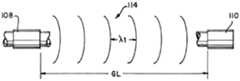
도 1은 카테터 및 어드밴서(advancer) 상에 배치된 감지 요소의 전방측 사시도이다.
도 2a는 비수축 위치에 있는 힘 감지 요소의 측면도이다.
도 2b는 전형적으로 장애물과 접촉하는 수축 위치에 있는 힘 감지 요소의 측면도이다.
도 3a는 휴지(at rest) 위치에서의 신호 상태인 송신기 및 센서의 도면이다.
도 3b는 접촉 위치에서의 신호 상태인 송신기 및 센서의 도면이다.
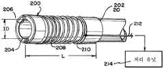
도 4는 감지 요소의 전방측 사시도이다.
도 5는 폐의 신속 해부학적 맵핑(Fast Anatomical Mapping, FAM) 가지(branch)에 의해 생성된 3D 이미지의 일례이다.
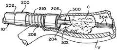
도 6은 전진 위치에 있는 본 발명의 장애물 포획 디바이스의 전방측 사시도이다.
도 7은 포획 위치에 있는 본 발명의 장애물 포획 디바이스의 전방측 사시도이다.
도 8a는 장애물과 만나는 맥관구조 내의 장애물 감지 및 포획 디바이스를 도시한다.
도 8b는 장애물 포획 디바이스의 전개를 도시한다.
도 8c는 전개된 장애물 포획 디바이스를 도시한다.
도 9는 본 발명의 방법의 일례의 흐름도이다.
도 10은 본 발명의 방법의 일례의 다른 흐름도이다.The above and further aspects of the invention are further discussed with reference to the following description in conjunction with the accompanying drawings, wherein like reference numerals refer to like structural elements and features in the various figures. The drawings are not necessarily drawn to scale, but instead focus on illustrating the principles of the invention. The drawings show one or more implementations of the device of the present invention by way of example only and not limitation.
1 is a front side perspective view of a sensing element disposed on a catheter and an advancer.
2A is a side view of the force sensing element in the non-retracted position.
2B is a side view of the force sensing element, typically in a retracted position in contact with an obstacle.
3A is a diagram of a transmitter and sensor in signal state in an at rest position.
3B is a diagram of a transmitter and a sensor in signal state at the contact position.
4 is a front side perspective view of the sensing element.
5 is an example of a 3D image generated by the Fast Anatomical Mapping (FAM) branch of the lung.
6 is a front side perspective view of the obstacle capture device of the present invention in an advanced position.
7 is a front side perspective view of the obstacle capture device of the present invention in a capture position.
8A illustrates an obstacle sensing and capture device in a vasculature that meets the obstacle.
8B illustrates deployment of the obstacle capture device.
8C shows the deployed obstacle capture device.
9 is a flowchart of an example of the method of the present invention.
10 is another flow chart of an example of the method of the present invention.
도 1, 도 2a 및 도 2b는 중심 루멘(16)을 갖는, 힘 검출을 사용하는 장애물 감지 요소(100)를 도시한다. 도 1은 근위 단부(12), 원위 단부(14) 및 내부 루멘(16)을 갖는 카테터(10)를 도시한다. 근위 단부(12)에는 카테터(10)를 조향하기 위한 손잡이, 본 발명을 지원하는 소정 전자장치, 및 장애물 포획 디바이스(300)를 위한 어드밴서가 있을 수 있다. 카테터(10)의 원위 단부(14)에는 힘 감지 요소(100)가 배치될 수 있다.1, 2A and 2B show an
힘 감지 요소(100)는 근위 단부(102), 원위 단부(104), 및 이들 사이의 갭(106)을 포함할 수 있다. 전자기 송수신기(108)가 힘 감지 요소(100)의 근위 단부(102)에 고정될 수 있다. 전자기 센서(110)가 힘 감지 요소(100)의 원위 단부(104)에 배치될 수 있고, 갭(106)에 의해 송수신기(108)로부터 분리될 수 있다. 전자기 센서(110)는 또한 힘 감지 요소(100)를 따라 활주가능하다. 스프링(112)이 송수신기(108)와 센서(110) 사이에 배치되고, 센서(110)의 근위방향 이동에 대한 저항을 제공한다.The
장애물 감지 요소(100)는 카테터(10)의 팁이 맥관구조(V) 내의 장애물(C)과 접촉하는지를 판정하기 위해 힘 감지 요소로서 작용한다(도 3a 및 도 3b 참조). 장애물(C)은 전형적으로 혈전이지만, 센서는 이전에 전개된 스텐트(stent) 또는 다른 자연 또는 이식된 특징부를 포함한 임의의 장애물에 대한 영향을 감지하기 위해 사용될 수 있다. 장애물(C)과의 접촉을 판정하기 위해, 송수신기(108)는 신호(114)를 송신할 수 있고, 그 신호는 센서(110)에 의해 수신된다. 센서(110)는 카테터(10)를 따라 변위가능하고, 스프링(112)은 원위방향으로 지향된 힘을 인가한다. 센서(110)가 장애물(C)과 접촉하는 경우, 이는 근위방향으로 밀려서, 센서(110)와 송수신기(108) 사이의 갭(106)을 폐쇄한다. 달리 말하면, 비수축 상태에서, 갭(106)은 휴지 갭 길이(GL)를 갖고, 이어서 일단 접촉 상태가 되면, 갭(106)은 수축하여 센서(110)와 송수신기(108) 사이의 거리가 이제 접촉 갭 길이(GL1)로 된다. 접촉 갭 길이(GL1)는 휴지 갭 길이(GL)보다 항상 작다(즉, GL > GL1). 이러한 거리의 변화는 수신된 신호의 특성을 변화시키고 위치 신호를 제공한다.The
센서(110)는 송수신기(108)로부터 수신되는 신호가 주파수(F1) 또는 주파수(F2) 또는 주파수(Fn)의 주파수를 갖는지를 검출할 수 있다. 이어서, 송수신기(108)는 송수신기(108)가, 일례에서, 고정된 초기 주파수 및/또는 파장을 갖는 신호를 방출하기 때문에 송수신기(108)에 대한 센서(110)의 상대 위치를 알 수 있다. 센서(110)는 신호를 수신/송신할 수 있는 코일일 수 있다. 일례에서, 센서(110)는 수신된 신호에 기초하여 충전 및 방전하는 수동 코일일 수 있다.The
송수신기(108)로부터의 방출된 신호는 스프링(112) 압축을 검출하기 위한 주파수를 가질 수 있다. 스프링 압축은 그가 혈전(C) 변형에 기초하여 충분한 거리 변화를 가질 수 있는 방식으로 스프링 상수(k)로 조정될 수 있다. 혈전(C)이 스프링(112)에 부딪히는 경우, 스프링은 압축되어, 카테터(10)가 혈전에 부딪히지 않은 경우보다 짧은 거리를 야기한다. 이러한 압축은 송수신기(108)로부터 센서(110)로의 신호가 더 빨리 이동하는 결과를 야기하고, 신호는 더 높은 강도를 가질 수 있다. 따라서, 센서(110)는 카테터(10)의 원위 단부(14)가 장애물(C)과 만났는지를 검출할 수 있다. 도 3a 및 도 3b를 참조한다.The emitted signal from the
대안적으로, 센서(110)가 제1 위치에 있는 경우, 즉 비접촉 상태인 경우, 도 3a에 도시된 바와 같이, 센서(110)에 의해 수신된 신호(114)는 제1 주파수(F1), 파장(λ1), 및 제1 전력(P1)을 포함한다. 송수신기(108) 및 센서(110)는 전체 갭 길이(GL)를 갖는 휴지 위치에 있다. 센서(110)가 장애물(C)과 접촉할 때, 이는 제2 위치(장애물 접촉)로 이동하고, 센서(110)에 의해 수신된 신호(114)는 이제 제2 파장(λ2) 및 제2 전력(P2)으로 인해 제2 주파수(F2)를 갖는데, 이는 도 3b에 도시된 바와 같다.Alternatively, when the
당업자는 주파수 및 파장이 광속(c)을 통해 관련된다는 것(F=c/λ)을 알고 있다. 움직임 동안 센서(110)에 의해 식별된 주파수/파장의 감지된 변화는 도플러 효과의 결과일 수 있다. 방출 주파수(F1) 및 제2 주파수(F2)를 알면, 센서(110)가 이동한 거리가 계산될 수 있다. 더욱이, 스프링(112)의 스프링 상수(k)를 알면, 센서(110)를 검출된 거리만큼 이동시키는 데 얼마나 큰 힘이 필요한지를 계산할 수 있게 된다. 이어서, 필요한 힘은 장애물(C)의 일반적인 특성을 결정하는 데 사용될 수 있다. 송신 신호 전력(P1)과 수신 신호 전력(P2)의 차이는 또한 센서(110)가 이동한 거리를 결정하도록 교정될 수 있다. 센서(110)가 송수신기(108)에 더 가깝게 이동함에 따라, 전력은 증가한다. 따라서, 제1 주파수(F1), 제2 주파수(F2), 제1 전력(P1), 및/또는 제2 전력(P2)에 기초하여 위치 신호가 생성될 수 있다. 힘 감지 요소(100)는 또한, 후술되는 바와 같이, 신속 해부학적 맵핑(FAM) 센서를 포함할 수 있다.One skilled in the art knows that the frequency and wavelength are related via the luminous flux c (F = c / λ). The sensed change in frequency / wavelength identified by
도 4 및 도 5는 중심 루멘(206)을 갖는 신속 해부학적 맵핑(FAM) 센서 또는 전자기 감지 요소(200)의 추가 예를 도시한다. 전자기 감지 요소(200)는 근위 단부(202), 원위 단부(204), 및 그를 통한 루멘(206)을 갖는다. 내부 루멘(206)은 신경맥관 디바이스를 통과시키도록 구성된 내경(ID)을 갖는다. 전자기 감지 요소(200)는 근위 단부(202)에서 원위 단부(204)에 이르는 중공 튜브(208)를 가질 수 있고 내부 루멘(206)을 공유한다. 코일(210)은 튜브(208) 둘레에 권취될 수 있고, 내부 루멘(206) 외측에 배치될 수 있고, 맵핑 신호를 제공할 수 있다. 와이어(212)가 코일(210)에 연결될 수 있고, 맵핑 신호를 프로세서(214)에 송신할 수 있다. 전형적인 FAM 센서는 신경맥관 디바이스를 통과시키기 위한 내부 루멘(206)을 갖지 않는다. 이는 맵핑이 먼저 수행되어야 하고 이어서 신경맥관 디바이스가 도입될 수 있기 때문에 수술 과정에 가외의 단계를 추가한다. 본 발명에서, 신경맥관 디바이스는 맵핑이 수행되고 있을 때 도입될 수 있다. 따라서, 전자기 감지 요소(200)의 위치 정확도를 손상시키지 않고서 혈전 회수 디바이스가 도입 및 사용될 수 있다.4 and 5 show further examples of a fast anatomical mapping (FAM) sensor or
전자기 감지 요소(200)의 일례는 하기와 같이 구성된 코일 유사 인덕터일 수 있다. 매우 얇은 층의 중공 강성 페라이트 튜브(208)는 대략 전자기 감지 요소(200)의 길이(L)일 수 있고, 내경(ID)은 카테터 외피(도시되지 않음)의 내경과 동일할 수 있다. 와이어(코일)(210)가 얇은 층 페라이트 튜브(208) 상에 권취될 수 있다. 센서 와이어(212), 일례에서, 얇은 꼬인 쌍 와이어는 센서 코일로부터 처리 유닛(214)으로 맵핑 신호를 전달하는 센서로서 작용하는 권취된 코일(210) 상에 솔더에 의해 부착될 수 있다. 전자기 감지 요소(200)의 개방 내경(ID)/루멘(206)은 신경맥관 기기가 통과하게 한다.One example of an
전자기 감지 요소(200)를 배치하면, 디바이스의 원위 단부(204)는 외과의가 장애물/혈전(C)의 위치를 찾으려고 시도할 때 카테터가 맥관 내에 있는 곳을 그녀가 정확히 알게 한다. 이는 카테터(10)가 전진될 때 3D 이미지를 플로팅함으로써 행해진다. 도 5는 혈관 가지와 매우 유사한 폐 기도 가지의 플롯을 도시한다. 이점들 중 하나는, 3D 이미지가 구성되는 방향으로 카테터가 전진되고 어떠한 혈전도 발견되지 않는 경우, 외과의가 동일한 통로를 다시 추적할 필요가 없다는 것이다.Placing the
도 6 및 도 7은 환자의 맥관(V) 내의 혈전/장애물(C)을 제거하기 위한 디바이스(300)의 일례를 도시한다. 디바이스(300)는 일단 장애물(C)이 전술된 요소들(100, 200) 중 적어도 하나를 사용하여 위치되면 카테터(10)를 통과하도록 크기설정된 전달 튜브(302)를 포함한다. 다수의 포획 앵커(304)가 전달 튜브(302) 내에 배치된다. 포획 앵커(304)는 그가 전진 위치 및 포획 위치를 갖게 하는 형상 기억 재료로 제조될 수 있다. 전진 위치에서, 포획 앵커(304)는 대체로 직선이며, 전달 튜브(302)의 중심축(306)에 대략 평행하다. 이러한 위치는 도 6에 도시되어 있으며, 디바이스(300)가 카테터(10)를 통해 치료 위치로 용이하게 이동되게 한다. 포획 앵커(304)의 대체로 직선인 특성은 또한 혈전을 관통하는 것을 돕는다(도 8b 참조).6 and 7 show an example of a
포획 앵커(304)가 포획 위치에 있을 때, 복수의 앵커(304) 각각의 원위 단부(308)가 외향으로 확장되고 근위방향으로 만곡부(310)로 확장한다. 달리 말하면, 포획 앵커(304)는 그가 중심축(306)으로부터 멀리 확장되고 앵커(304)의 팁이 전달 튜브(302)를 향해 후방으로 만곡됨에 따라 "만개(bloom)"된다. 대안적으로, 복수의 포획 앵커(304)는 원주방향으로 확장될 수 있다. 따라서, 앵커(304)의 최원위 부분은 만곡부(310)이고, 앵커(304)의 팁(308)은 근위방향으로 뾰족해진다. 포획 앵커(304)가 만곡됨에 따라, 그는 대략 그가 전개되는 혈관의 직경으로 확장된다. 그러한 방식으로, 그는 혈전(C)을 혈관으로부터 제거하기 위해 혈전의 대부분 내로 고정될 수 있다. 전달 튜브(302)가 다시 카테터(10) 내로 당겨짐에 따라, 장애물(C)은 앵커(304)에 의해 그리고 복수의 앵커(304) 각각의 만곡부(310) 내에 포획된다. 대안적으로, 장애물(C)이 카테터(10) 내로 변위될 필요는 없지만, 장애물은 카테터(10) 및 전달 튜브(302) 둘 모두를 근위방향으로 변위시킴으로써 제거된다. 혈전이 이동될 때 카테터(10)를 통해 흡인이 일어나서, 혈전의 임의의 표유하는 조각(stray piece)이 떨어져 나와서 혈류를 통과하는 것을 감소시키거나 제거할 수 있다. 일 실시예에서, 앵커(304)는 탄력성 재료, 예컨대 스프링-템퍼(spring-temper) 스테인리스강, 또는 더욱 바람직하게는 초탄성 재료, 예컨대 니티놀(Nitinol)로 제조될 수 있다.When the
도 8a 내지 도 8c는 혈전(C) 제거의 일례를 도시한다. 카테터(10)는, 전자기 감지 요소(200)를 사용하여 3D 이미지가 생성되는 동안(신속 해부학적 맵핑), 다수의 혈관을 통해 전진된다. 카테터(10)는 힘 센서(100)에 의해 카테터(10)의 팁에서 저항이 감지될 때까지 전진된다. 이는 전형적으로 혈전(C)이 위치되었다는 표시이다. 도 8a를 참조한다. 다음으로, 혈전 회수 디바이스(300)가 전개되는데, 이때 니티놀 앵커(304)는 혈전이 완전히 관통되었을 때까지 그의 직선 전진 위치에 있다. 도 8b를 참조한다. 앵커(304)는 그의 포획 위치로 더 전진되어, 혈관(V)의 벽을 향해 원주방향으로 확장되는 다수의 니티놀의 사전형성된 형상을 야기한다. 마지막으로, 혈전(C)은 카테터 루멘(16) 내로 당겨질 수 있고, 전체 시스템이 제거된다.8A-8C show an example of thrombus (C) removal. The
도 9 및 도 10은 환자 맥관(V)을 통해 혈전 감지 요소(100, 200)를 갖는 카테터(10)를 전진시키는 단계(단계(400))를 갖는, 혈전을 검출 및 회수하는 방법을 예시한다. 혈전 감지 요소의 원위 단부에 배치된 전자기 센서(200)를 사용하면, 환자 맥관(V)은 FAM을 사용하여 실시간으로 맵핑될 수 있다(단계(402)). 일단 카테터(10)의 팁이 혈전과 접촉하면, 힘 센서(100)는 혈전 감지 요소(100, 200)가 환자 맥관(V) 내의 혈전(C)과 접촉하였음을 나타내는 위치 신호를 생성한다(단계(404)). 혈전 회수 디바이스(300)가 혈전(C)을 환자 맥관(V)으로부터 제거하기 위해 카테터(10) 및 루멘(16, 206)을 통해 전개될 수 있다(단계(406)).9 and 10 illustrate a method of detecting and retrieving thrombi having a step (step 400) of advancing the
전개하는 단계(단계(406))는, 또한, 전진 위치에서 복수의 포획 앵커(304)를 사용하여 혈전(C)을 관통하는 단계(단계(408))를 포함할 수 있다. 복수의 포획 앵커(304)는 포획 위치로 확장될 수 있고(단계(410)), 혈전 회수 디바이스(300)는 혈전(C)의 적어도 일부분과 함께 카테터(10) 내로 다시 후퇴된다(단계(412)). 후퇴하는 단계(412)는, 또한, 카테터(10)를 통해 흡인하는 단계(단계(414))를 포함할 수 있다.Deploying (step 406) may also include penetrating thrombus C using a plurality of capture anchors 304 in a forward position (step 408). The plurality of capture anchors 304 can be expanded to the capture position (step 410), and the
생성하는 단계(단계(404))는 전자기 송수신기(108)를 혈전 감지 요소(100, 200)의 근위 단부(102)에 배치하는 단계(단계(416)), 및 전자기 센서(110)를 송수신기(108)로부터 제1 거리(GL)에 배치하는 단계(단계(418))를 가질 수 있다. 스프링(112)이 송수신기(108)와 센서(110) 사이에 배치될 수 있어서, 스프링(112)은 센서(110)의 근위방향 이동에 대한 저항을 제공한다(단계(420)). 송수신기(108)는 센서(110)에서 수신될(단계(424)) 수 있는 신호를 방출할 수 있다(단계(422)). 일례에서, 프로세서는 신호의 주파수의 변화 및 신호의 전력의 변화 중 적어도 하나에 기초하여 센서(110)의 근위방향 이동을 결정할 수 있다(단계(426)). 이는 센서(100)의 근위방향 이동에 기초하여 위치 신호를 생성할 수 있다(단계(428)). 방출된 신호는, 일례에서, 고정된 파장/주파수에 있을 수 있다.Generating (step 404) includes placing the
수신하는 단계(단계(424))는 센서(110)가 제1 거리(GL)에 있는 경우에 제1 주파수 및 제1 전력을 포함하는 신호를 센서(110)에서 수신하는 단계(단계(430))를 포함할 수 있다. 이어서, 센서(110)가 제1 거리(GL)보다 짧은 제2 거리(GL1)에 있는 경우에 제2 주파수 및 제2 전력을 포함하는 신호를 센서(110)에서 수신하는 단계(단계(432)). 제1 주파수로부터 제2 주파수로의 변화는 제1 거리(GL)로부터 제2 거리(GL1)로의 변화에 기초할 수 있다. 또한, 제1 전력으로부터 제2 전력으로의 변화도 또한 제1 거리로부터 제2 거리로의 변화에 기초할 수 있다.Receiving (step 424) is a step of receiving at the sensor 110 a signal comprising a first frequency and a first power when the
맵핑 단계(단계(402))는 근위 단부(202), 원위 단부(204) 및 내부 루멘(206)을 갖는 중공 튜브(208)를 배치하는 단계(단계(434))를 포함할 수 있다. 이어서, 내부 루멘(206) 외측에 배치되고, 맵핑 신호를 제공하는 코일(210)을 튜브(208) 둘레에 권취하는 단계(단계(436)); 및 코일(210)에 와이어(212)를 연결하여 맵핑 신호를 프로세서(214)에 송신하는 단계(단계(438)). 내부 루멘(206)은 색전 코일(embolic coil), 유동 전환기(flow diverter) 및 스텐트와 같은 신경맥관 디바이스를 통과시키도록 구성된 내경(ID)을 가질 수 있다.The mapping step (step 402) may include placing a
전술된 바와 같이, 중공 튜브(208)는 대략 전자기 감지 요소(200)의 길이(L)인 중공 강성 페라이트 튜브를 가질 수 있고, 와이어(212)는 꼬인 쌍일 수 있다.As described above, the
상기 예는 방사선불투과성이고 형광투시법 하에서 가시적일 수 있는 하나 이상의 요소를 고려하는 것에 유의하여야 한다. 요소는 카테터(10)가 전진되고 환자 외부로 후퇴될 때 마커로서 사용될 수 있다.It should be noted that the above example considers one or more elements that are radiopaque and may be visible under fluoroscopy. The element may be used as a marker when the
상기 내용이 최선의 모드 및/또는 다른 예인 것으로 여겨지는 것을 설명하였으나, 다양한 변형예가 상기 내용 내에서 이루어 질 수 있다는 것이, 본 명세서에 개시된 주제가 다양한 형태 및 예로 구현될 수 있다는 것이, 그리고 교시 내용이 본 명세서에서 단지 일부만이 설명된 많은 응용예들에 적용될 수 있다는 것이 이해된다. 하기 청구범위는 본 교시 내용의 진정한 범주 내에 있는 임의의 그리고 모든 응용예, 변형예, 및 변경예를 청구하려는 것이다.While the foregoing has described what is considered to be the best mode and / or other example, it is understood that various modifications may be made within the disclosure that the subject matter disclosed herein may be embodied in various forms and examples, and that the teachings It is understood that only some of the description herein can be applied to many of the applications described. The following claims are intended to claim any and all applications, modifications, and variations that fall within the true scope of the present teachings.
Claims (16)
Translated fromKorean내부 루멘, 원위 단부, 및 상기 원위 단부에 배치된 상기 감지 요소를 포함하는 카테터;
신호의 방출 또는 수신 중 적어도 하나를 수행하고, 상기 감지 요소의 근위 단부에 고정되는 전자기 송수신기;
상기 신호를 수신하고, 상기 감지 요소의 원위 단부에 배치되고, 상기 감지 요소를 따라 활주가능하고, 위치 신호를 생성하는 전자기 센서; 및
상기 송수신기와 상기 센서 사이에 배치되어 상기 센서의 근위방향 이동에 대한 저항을 제공하는 스프링을 포함하고,
상기 센서가 제1 위치에 있는 경우, 상기 센서에 의해 수신된 상기 신호는 제1 주파수 및 제1 전력을 포함하고;
상기 센서가 제2 위치에 있는 경우, 상기 센서에 의해 수신된 상기 신호는 제2 주파수 및 제2 전력을 포함하고;
상기 위치 신호는 상기 제1 주파수, 상기 제2 주파수, 상기 제1 전력, 및 상기 제2 전력 중 적어도 하나에 기초하여 생성되는, 힘 감지 요소.As a force sensing element with a center lumen,
A catheter comprising an inner lumen, a distal end, and the sensing element disposed at the distal end;
An electromagnetic transceiver for performing at least one of the emission or reception of a signal, the electromagnetic transceiver being fixed to the proximal end of the sensing element;
An electromagnetic sensor receiving the signal, disposed at the distal end of the sensing element, slidable along the sensing element, the electromagnetic sensor generating a position signal; And
A spring disposed between the transceiver and the sensor to provide a resistance to proximal movement of the sensor,
When the sensor is in a first position, the signal received by the sensor includes a first frequency and a first power;
When the sensor is in a second position, the signal received by the sensor includes a second frequency and a second power;
And the position signal is generated based on at least one of the first frequency, the second frequency, the first power, and the second power.
상기 제1 위치는 상기 감지 요소 상의 완전 원위 위치이고,
상기 제2 위치는 상기 송수신기 근처의 근위 위치인, 힘 감지 요소.The method of claim 1,
The first position is a full distal position on the sensing element,
And the second position is a proximal position near the transceiver.
근위 단부, 원위 단부, 및 내부 루멘을 포함하는 중공 튜브;
상기 튜브 둘레에 권취되고, 상기 내부 루멘 외측에 배치되고, 맵핑 신호를 제공하는 코일; 및
상기 코일에 연결되고 상기 맵핑 신호를 프로세서에 송신하는 와이어를 포함하고,
상기 중심 루멘은 신경맥관 디바이스를 통과시키도록 구성된 내경을 갖는, 전자기 감지 요소.An electromagnetic sensing element with a center lumen
A hollow tube comprising a proximal end, a distal end, and an inner lumen;
A coil wound around the tube and disposed outside the inner lumen and providing a mapping signal; And
A wire connected to the coil and transmitting the mapping signal to a processor;
Wherein the central lumen has an inner diameter configured to pass a neurovascular device.
상기 튜브는 대략 상기 전자기 감지 요소의 길이인 중공 강성 페라이트 튜브를 포함하고;
상기 와이어는 꼬인 쌍(twisted pair)인, 전자기 감지 요소.The method of claim 5,
The tube comprises a hollow rigid ferrite tube approximately the length of the electromagnetic sensing element;
The wire is a twisted pair.
전달 튜브; 및
전진 위치 및 포획 위치를 포함하고, 상기 전달 튜브 내에 배치되는 복수의 포획 앵커(anchor)들을 포함하고;
상기 복수의 포획 앵커들이 상기 전진 위치에 있는 경우, 상기 복수의 포획 엥커들은 상기 전달 튜브의 중심축에 대략 평행하고,
상기 복수의 포획 앵커들이 상기 포획 위치에 있는 경우, 상기 복수의 앵커들 각각의 원위 단부는 외향으로 확장되고 근위방향으로 만곡되는, 디바이스.A device for removing obstacles in the vasculature,
Delivery tube; And
A plurality of capture anchors disposed in the delivery tube, the forward position and the capture position;
When the plurality of capture anchors are in the forward position, the plurality of capture anchors are approximately parallel to the central axis of the delivery tube,
And when the plurality of capture anchors are in the capture position, the distal end of each of the plurality of anchors extends outwardly and curves proximally.
혈전 감지 요소를 갖는 카테터를 환자 맥관을 관통하여 전진시키는 단계;
상기 혈전 감지 요소의 원위 단부에 배치된 전자기 센서를 사용하여, 상기 환자 맥관을 맵핑하는 단계;
힘 센서로부터, 상기 혈전 감지 요소가 상기 환자 맥관 내의 혈전과 접촉하였음을 나타내는 위치 신호를 생성하는 단계; 및
상기 환자 맥관으로부터 상기 혈전을 제거하기 위해 상기 카테터 및 상기 혈전 감지 요소 내의 루멘을 통해 혈전 회수 디바이스를 전개하는 단계를 포함하는, 방법.As a method for detecting and recovering thrombi,
Advancing the catheter with a thrombus sensing element through the patient vessel;
Mapping the patient vasculature using an electromagnetic sensor disposed at the distal end of the thrombus sensing element;
Generating, from a force sensor, a position signal indicating that the thrombus sensing element has been in contact with a thrombus in the patient vessel; And
Deploying a thrombus recovery device through the lumen in the catheter and the thrombus sensing element to remove the thrombus from the patient vasculature.
전진 위치에서 복수의 포획 앵커들을 사용하여 상기 혈전을 관통하는 단계;
상기 복수의 포획 앵커들을 포획 위치로 확장시키는 단계; 및
상기 혈전 회수 디바이스를 상기 혈전의 일부분과 함께 상기 카테터 내로 다시 후퇴시키는 단계를 추가로 포함하는, 방법.The method of claim 10, wherein the deploying step comprises:
Penetrating the thrombus using a plurality of capture anchors in an advanced position;
Expanding the plurality of capture anchors to a capture position; And
Retracting the thrombus recovery device back into the catheter with a portion of the thrombus.
전자기 송수신기를 상기 혈전 감지 요소의 근위 단부에 배치하는 단계;
상기 혈전 감지 요소의 원위 단부에 있는 전자기 센서를 상기 송수신기로부터 제1 거리에 배치하는 단계;
상기 센서의 근위방향 이동에 대한 저항을 제공하는 스프링을 상기 송수신기와 상기 센서 사이에 배치하는 단계;
상기 송수신기로부터 신호를 방출하는 단계;
상기 센서에서 상기 신호를 수신하는 단계;
상기 신호의 주파수의 변화 및 상기 신호의 전력의 변화 중 적어도 하나에 기초하여 상기 센서의 근위방향 이동을 결정하는 단계; 및
상기 센서의 근위방향 이동에 기초하여 상기 위치 신호를 생성하는 단계를 포함하는, 방법.The method of claim 10, wherein the generating step,
Positioning an electromagnetic transceiver at the proximal end of the thrombus sensing element;
Placing an electromagnetic sensor at the distal end of the thrombus sensing element at a first distance from the transceiver;
Disposing a spring between the transceiver and the sensor providing a resistance to proximal movement of the sensor;
Emitting a signal from the transceiver;
Receiving the signal at the sensor;
Determining a proximal movement of the sensor based on at least one of a change in frequency of the signal and a change in power of the signal; And
Generating the position signal based on proximal movement of the sensor.
상기 센서가 상기 제1 거리에 있는 경우에 제1 주파수 및 제1 전력을 포함하는 상기 신호를 상기 센서에서 수신하는 단계; 및
상기 센서가 상기 제1 거리보다 짧은 제2 거리에 있는 경우에 제2 주파수 및 제2 전력을 포함하는 상기 신호를 상기 센서에서 수신하는 단계를 포함하고;
상기 제1 주파수로부터 상기 제2 주파수로의 변화는 상기 제1 거리로부터 상기 제2 거리로의 변화에 기초하고,
상기 제1 전력으로부터 상기 제2 전력으로의 변화는 상기 제1 거리로부터 상기 제2 거리로의 변화에 기초하는, 방법.The method of claim 13, wherein the receiving step,
Receiving at the sensor the signal comprising a first frequency and a first power when the sensor is at the first distance; And
Receiving at the sensor the signal comprising a second frequency and a second power when the sensor is at a second distance shorter than the first distance;
The change from the first frequency to the second frequency is based on the change from the first distance to the second distance,
The change from the first power to the second power is based on a change from the first distance to the second distance.
근위 단부, 원위 단부, 및 내부 루멘을 포함하는 중공 튜브를 배치하는 단계;
상기 내부 루멘 외측에 배치되고 맵핑 신호를 제공하는 코일을 상기 튜브 둘레에 권취하는 단계; 및
상기 코일에 와이어를 연결하고 상기 맵핑 신호를 프로세서에 송신하는 단계를 포함하고,
상기 내부 루멘은 신경맥관 디바이스를 통과시키도록 구성된 내경을 갖는, 방법.The method of claim 10, wherein the mapping step,
Placing a hollow tube comprising a proximal end, a distal end, and an inner lumen;
Winding a coil around the tube disposed outside the inner lumen and providing a mapping signal; And
Connecting a wire to the coil and transmitting the mapping signal to a processor;
Wherein the inner lumen has an inner diameter configured to pass a neurovascular device.
상기 중공 튜브는 대략 상기 전자기 감지 요소의 길이인 중공 강성 페라이트 튜브를 포함하고;
상기 와이어는 꼬인 쌍인, 방법.The method of claim 15,
The hollow tube comprises a hollow rigid ferrite tube approximately the length of the electromagnetic sensing element;
The wire is a twisted pair.
Applications Claiming Priority (2)
| Application Number | Priority Date | Filing Date | Title |
|---|---|---|---|
| US16/001,427 | 2018-06-06 | ||
| US16/001,427US11839460B2 (en) | 2018-06-06 | 2018-06-06 | Device and method to detect and remove blood clots for treatment of ischemic stroke using force and electromagnetic sensing |
Publications (2)
| Publication Number | Publication Date |
|---|---|
| KR20190139147Atrue KR20190139147A (en) | 2019-12-17 |
| KR102704493B1 KR102704493B1 (en) | 2024-09-11 |
Family
ID=66998065
Family Applications (1)
| Application Number | Title | Priority Date | Filing Date |
|---|---|---|---|
| KR1020190066398AActiveKR102704493B1 (en) | 2018-06-06 | 2019-06-05 | A device and method to detect and remove blood clots for treatment of ischemic stroke using force and electromagnetic sensing |
Country Status (7)
| Country | Link |
|---|---|
| US (2) | US11839460B2 (en) |
| EP (1) | EP3578223B1 (en) |
| JP (1) | JP7408301B2 (en) |
| KR (1) | KR102704493B1 (en) |
| CN (1) | CN110559538B (en) |
| BR (1) | BR102019011419A2 (en) |
| ES (1) | ES2971075T3 (en) |
Families Citing this family (6)
| Publication number | Priority date | Publication date | Assignee | Title |
|---|---|---|---|---|
| CN113164181A (en) | 2018-08-24 | 2021-07-23 | 尼尔拉维有限公司 | Device for managing acute ischemic events |
| US11679195B2 (en) | 2021-04-27 | 2023-06-20 | Contego Medical, Inc. | Thrombus aspiration system and methods for controlling blood loss |
| EP4108188A1 (en)* | 2021-06-23 | 2022-12-28 | Artedrone | Medical device, system and method for retrieving a thrombus from a vessel, and method for producing a device |
| WO2024091571A1 (en)* | 2022-10-26 | 2024-05-02 | Microvention, Inc. | Systems and methods to provide haptic feedback on clot engagement |
| US12370078B2 (en) | 2023-10-27 | 2025-07-29 | NEXT Life Sciences, Inc. | Apparatus and method for delivery and/or removal of occlusions in the body |
| CN118625722B (en)* | 2024-08-09 | 2024-10-29 | 浙江巴泰医疗科技有限公司 | Pipe pressing device control system of suction device |
Citations (10)
| Publication number | Priority date | Publication date | Assignee | Title |
|---|---|---|---|---|
| US20020198492A1 (en)* | 2001-06-26 | 2002-12-26 | John Miller | Balloon catheter |
| US20060106375A1 (en)* | 2004-11-15 | 2006-05-18 | Werneth Randell L | Ablation system with feedback |
| US20070293928A1 (en)* | 2006-06-14 | 2007-12-20 | Damian Tomlin | Retrieval device with sidewall grippers |
| US20080009772A1 (en)* | 2003-11-26 | 2008-01-10 | Wicab, Inc. | Systems and methods for altering brain and body functions and for treating conditions and diseases of the same |
| KR20090036075A (en)* | 2007-10-08 | 2009-04-13 | 바이오센스 웹스터 인코포레이티드 | Catheter with Pressure Sensing |
| EP2449996A2 (en)* | 2010-11-03 | 2012-05-09 | Biosense Webster (Israel), Ltd. | Zero-drift detection and correction in contact force measurements |
| US20130317425A1 (en)* | 2012-04-30 | 2013-11-28 | BiO2 Medical, Inc. | Multi-lumen central access vena cava filter apparatus for clot management and method of using same |
| EP2679149A1 (en)* | 2012-06-25 | 2014-01-01 | Biosense Webster (Israel), Ltd. | Probe with a distal sensor and with a proximal cable connected to a wireless tranceiver |
| KR20150060735A (en)* | 2012-08-27 | 2015-06-03 | 유니버시티 오브 휴스턴 | Robotic device and system software, hardware and methods of use for image-guided and robot-assisted surgery |
| KR20180079372A (en)* | 2015-10-30 | 2018-07-10 | 아클라런트, 인코포레이션 | System and method for navigating surgical instruments |
Family Cites Families (7)
| Publication number | Priority date | Publication date | Assignee | Title |
|---|---|---|---|---|
| US6511492B1 (en) | 1998-05-01 | 2003-01-28 | Microvention, Inc. | Embolectomy catheters and methods for treating stroke and other small vessel thromboembolic disorders |
| US20070016069A1 (en)* | 2005-05-06 | 2007-01-18 | Sorin Grunwald | Ultrasound sensor |
| US8636715B2 (en)* | 2006-09-25 | 2014-01-28 | Medtronic Vascular, Inc. | High torque, low profile catheters and methods for transluminal interventions |
| US8535308B2 (en) | 2007-10-08 | 2013-09-17 | Biosense Webster (Israel), Ltd. | High-sensitivity pressure-sensing probe |
| US9204841B2 (en)* | 2012-12-31 | 2015-12-08 | Biosense Webster (Israel) Ltd. | Catheter with serially connected sensing structures and methods of calibration and detection |
| EP3043735A1 (en)* | 2013-11-07 | 2016-07-20 | St. Jude Medical, Cardiology Division, Inc. | Medical device with contact force sensing tip |
| US11367947B2 (en)* | 2015-03-16 | 2022-06-21 | St. Jude Medical International Holding S.á r.l. | Field concentrating antennas for magnetic position sensors |
- 2018
- 2018-06-06USUS16/001,427patent/US11839460B2/enactiveActive
- 2019
- 2019-06-03BRBR102019011419Apatent/BR102019011419A2/ennot_activeApplication Discontinuation
- 2019-06-05KRKR1020190066398Apatent/KR102704493B1/enactiveActive
- 2019-06-05ESES19178388Tpatent/ES2971075T3/enactiveActive
- 2019-06-05EPEP19178388.5Apatent/EP3578223B1/enactiveActive
- 2019-06-05JPJP2019105110Apatent/JP7408301B2/enactiveActive
- 2019-06-06CNCN201910491653.7Apatent/CN110559538B/enactiveActive
- 2023
- 2023-01-13USUS18/096,622patent/US12350033B2/enactiveActive
Patent Citations (10)
| Publication number | Priority date | Publication date | Assignee | Title |
|---|---|---|---|---|
| US20020198492A1 (en)* | 2001-06-26 | 2002-12-26 | John Miller | Balloon catheter |
| US20080009772A1 (en)* | 2003-11-26 | 2008-01-10 | Wicab, Inc. | Systems and methods for altering brain and body functions and for treating conditions and diseases of the same |
| US20060106375A1 (en)* | 2004-11-15 | 2006-05-18 | Werneth Randell L | Ablation system with feedback |
| US20070293928A1 (en)* | 2006-06-14 | 2007-12-20 | Damian Tomlin | Retrieval device with sidewall grippers |
| KR20090036075A (en)* | 2007-10-08 | 2009-04-13 | 바이오센스 웹스터 인코포레이티드 | Catheter with Pressure Sensing |
| EP2449996A2 (en)* | 2010-11-03 | 2012-05-09 | Biosense Webster (Israel), Ltd. | Zero-drift detection and correction in contact force measurements |
| US20130317425A1 (en)* | 2012-04-30 | 2013-11-28 | BiO2 Medical, Inc. | Multi-lumen central access vena cava filter apparatus for clot management and method of using same |
| EP2679149A1 (en)* | 2012-06-25 | 2014-01-01 | Biosense Webster (Israel), Ltd. | Probe with a distal sensor and with a proximal cable connected to a wireless tranceiver |
| KR20150060735A (en)* | 2012-08-27 | 2015-06-03 | 유니버시티 오브 휴스턴 | Robotic device and system software, hardware and methods of use for image-guided and robot-assisted surgery |
| KR20180079372A (en)* | 2015-10-30 | 2018-07-10 | 아클라런트, 인코포레이션 | System and method for navigating surgical instruments |
Also Published As
| Publication number | Publication date |
|---|---|
| US20230165483A1 (en) | 2023-06-01 |
| JP7408301B2 (en) | 2024-01-05 |
| EP3578223C0 (en) | 2024-01-10 |
| JP2019209148A (en) | 2019-12-12 |
| CN110559538A (en) | 2019-12-13 |
| BR102019011419A2 (en) | 2019-12-24 |
| EP3578223A2 (en) | 2019-12-11 |
| EP3578223A3 (en) | 2020-03-04 |
| ES2971075T3 (en) | 2024-06-03 |
| CN110559538B (en) | 2024-01-26 |
| US20190374128A1 (en) | 2019-12-12 |
| US12350033B2 (en) | 2025-07-08 |
| EP3578223B1 (en) | 2024-01-10 |
| US11839460B2 (en) | 2023-12-12 |
| KR102704493B1 (en) | 2024-09-11 |
Similar Documents
| Publication | Publication Date | Title |
|---|---|---|
| KR102704493B1 (en) | A device and method to detect and remove blood clots for treatment of ischemic stroke using force and electromagnetic sensing | |
| AU2016200819B2 (en) | Angioplasty guidewire | |
| JP5584958B2 (en) | Imaging apparatus and imaging method for blood vessel position and blood vessel shape | |
| US8216216B2 (en) | Ablation devices with sensor structures | |
| US11426256B2 (en) | Implantable markers, and systems and methods for using them | |
| US20240307128A1 (en) | Devices and methods for guide wire placement | |
| EP1585434B1 (en) | System for mounting an mps sensor on a catheter | |
| JP2023553077A (en) | Recovery system and method | |
| JP2025520565A (en) | Retrieval catheter | |
| US10155125B2 (en) | Reverse loop ablation device | |
| EP4358890A1 (en) | Systems for clot length and property characterization | |
| IL168153A (en) | Method and system for mounting an mps sensor on a catheter |
Legal Events
| Date | Code | Title | Description |
|---|---|---|---|
| PA0109 | Patent application | Patent event code:PA01091R01D Comment text:Patent Application Patent event date:20190605 | |
| PG1501 | Laying open of application | ||
| PA0201 | Request for examination | Patent event code:PA02012R01D Patent event date:20220602 Comment text:Request for Examination of Application Patent event code:PA02011R01I Patent event date:20190605 Comment text:Patent Application | |
| E902 | Notification of reason for refusal | ||
| PE0902 | Notice of grounds for rejection | Comment text:Notification of reason for refusal Patent event date:20240109 Patent event code:PE09021S01D | |
| E701 | Decision to grant or registration of patent right | ||
| PE0701 | Decision of registration | Patent event code:PE07011S01D Comment text:Decision to Grant Registration Patent event date:20240613 | |
| GRNT | Written decision to grant | ||
| PR0701 | Registration of establishment | Comment text:Registration of Establishment Patent event date:20240904 Patent event code:PR07011E01D | |
| PR1002 | Payment of registration fee | Payment date:20240905 End annual number:3 Start annual number:1 | |
| PG1601 | Publication of registration |