KR20190136306A - Lighting apparatus - Google Patents
Lighting apparatusDownload PDFInfo
- Publication number
- KR20190136306A KR20190136306AKR1020180061846AKR20180061846AKR20190136306AKR 20190136306 AKR20190136306 AKR 20190136306AKR 1020180061846 AKR1020180061846 AKR 1020180061846AKR 20180061846 AKR20180061846 AKR 20180061846AKR 20190136306 AKR20190136306 AKR 20190136306A
- Authority
- KR
- South Korea
- Prior art keywords
- heat
- thermal diffusion
- diffusion
- light emitting
- central axis
- Prior art date
- Legal status (The legal status is an assumption and is not a legal conclusion. Google has not performed a legal analysis and makes no representation as to the accuracy of the status listed.)
- Granted
Links
Images


Classifications
- F—MECHANICAL ENGINEERING; LIGHTING; HEATING; WEAPONS; BLASTING
- F21—LIGHTING
- F21V—FUNCTIONAL FEATURES OR DETAILS OF LIGHTING DEVICES OR SYSTEMS THEREOF; STRUCTURAL COMBINATIONS OF LIGHTING DEVICES WITH OTHER ARTICLES, NOT OTHERWISE PROVIDED FOR
- F21V29/00—Protecting lighting devices from thermal damage; Cooling or heating arrangements specially adapted for lighting devices or systems
- F21V29/50—Cooling arrangements
- F21V29/70—Cooling arrangements characterised by passive heat-dissipating elements, e.g. heat-sinks
- F21V29/74—Cooling arrangements characterised by passive heat-dissipating elements, e.g. heat-sinks with fins or blades
- F—MECHANICAL ENGINEERING; LIGHTING; HEATING; WEAPONS; BLASTING
- F21—LIGHTING
- F21Y—INDEXING SCHEME ASSOCIATED WITH SUBCLASSES F21K, F21L, F21S and F21V, RELATING TO THE FORM OR THE KIND OF THE LIGHT SOURCES OR OF THE COLOUR OF THE LIGHT EMITTED
- F21Y2115/00—Light-generating elements of semiconductor light sources
- F21Y2115/10—Light-emitting diodes [LED]
Landscapes
- Engineering & Computer Science (AREA)
- General Engineering & Computer Science (AREA)
- Arrangement Of Elements, Cooling, Sealing, Or The Like Of Lighting Devices (AREA)
- Non-Portable Lighting Devices Or Systems Thereof (AREA)
Abstract
Translated fromKoreanDescription
Translated fromKorean본 발명은 조명장치에 관련된 것으로, 보다 구체적으로 발열 소자의 방열 효율을 향상시킨 조명장치에 관한 것이다.The present invention relates to a lighting apparatus, and more particularly to a lighting apparatus that improves the heat radiation efficiency of the heat generating element.
일반적으로, 엘이디(Light Emitting Diode, 발광다이오드)는 전기에너지를 빛 에너지로 변환하는 반도체로 이루어진 발광 소자를 말한다. 이러한 발광 소자는 수명이 길고 저전력 구동이 가능하여 다양한 분야에서 광범위하게 이용되고 있다.In general, an LED refers to a light emitting device made of a semiconductor for converting electrical energy into light energy. Such a light emitting device has a long life and is capable of low power driving, and thus is widely used in various fields.
발광 소자는 오랜 시간 고온에 노출될 경우 자체 발열에 의하여 성능이 급격히 저하되거나 물리적 파손으로 인한 고장이 유발될 수 있다. 또한 제철소, 광산, 발전소 등 고온에 노출되는 환경에서 사용될 경우, 발광 소자의 내구성에 방열성이 큰 영향을 끼친다. 이와 같은 발광 소자의 방열은 조명 효율 저하라는 문제점을 유발한다.When a light emitting device is exposed to high temperature for a long time, its performance may be drastically degraded by self-heating or a failure may be caused by physical damage. In addition, when used in an environment exposed to high temperatures, such as steel mills, mines, power plants, the heat dissipation significantly affects the durability of the light emitting device. Such heat radiation of the light emitting device causes a problem of lowering the lighting efficiency.
상술한 문제점을 해결하기 위해, 발광 소자에서 발생된 열을 외부로 배출하기 위해 전도성 높은 금속성의 히트 싱크(heat sink)를 이용하거나 에너지를 공급받아 팬을 작동하는 강제냉각 방식을 이용하기도 한다.In order to solve the above-mentioned problems, a conductive metal heat sink is used to discharge heat generated from the light emitting device to the outside, or a forced cooling method of operating a fan by receiving energy may be used.
다만 히트싱크는 방열성이 우수하나 고중량으로 크기가 제한되고 제조비용을 증대시켜 전자제품의 박형화 및 경량화 경향에 반하는 문제가 있다. 별도 팬을 작동시키는 경우, 구동부 등의 추가 설비와 에너지원의 공급을 필요로 하는 등 에너지 효율이 떨어지고 제조비용이 올라가는 문제가 있다.However, heat sinks have excellent heat dissipation, but are limited in size to heavy weights and increase manufacturing costs, thereby causing a problem that tends to be thinner and lighter in electronic products. In the case of operating a separate fan, there is a problem in that energy efficiency is lowered and manufacturing costs are increased, such as requiring additional equipment such as a driving unit and supply of an energy source.
따라서 최소한의 무게를 가지면서도 방열효율이 극대화될 수 있는 방열구조의 조명장치의 개발이 요구된다.Therefore, it is required to develop a lighting device having a heat dissipation structure capable of maximizing heat dissipation efficiency with minimum weight.
본 발명이 해결하고자 하는 기술적 과제는, 자연 냉각 방식의 방열성능이 우수한 조명장치를 제공하는데 있다.The technical problem to be solved by the present invention is to provide a lighting device excellent in the heat radiation performance of the natural cooling method.
본 발명이 해결하고자 하는 기술적 과제는 상술된 것에 제한되지 않는다.The technical problem to be solved by the present invention is not limited to the above.
조명장치는, 일면에 복수 개의 발광 소자가 배치되어 면발광체를 이루는 발광 모듈; 및 상기 발광 모듈의 타면을 복개하는 열확산 하우징을 포함하고, 상기 열확산 하우징은, 중심축(axis) 상에 제1 열확산 홀이 형성된 열확산 플레이트와, 상기 열확산 플레이트의 외주연에 연장 형성되어 가장자리를 따라 복수 개의 제2 열확산 홀이 형성된 측면 열확산 서포트를 가지는 열확산 커버; 상기 열확산 커버의 타면에 평행한 방향으로 연장 형성되되, 상기 중심축(axis)을 중심으로 방사 형태로 마련된 복수의 열확산 핀; 및 상기 열확산 커버의 타면에 평행한 방향으로 연장 형성되되, 상기 중심축(axis)에 대하여 상기 제1 열확산 홀과 연통되도록 마련된 열확산 파이프를 포함할 수 있다.The lighting apparatus includes a light emitting module in which a plurality of light emitting elements are disposed on one surface to form a surface light emitting body; And a heat diffusion housing covering the other surface of the light emitting module, wherein the heat diffusion housing includes a heat diffusion plate having a first heat diffusion hole formed on a central axis, and an extension formed on an outer circumference of the heat diffusion plate, and along an edge thereof. A thermal diffusion cover having a side thermal diffusion support on which a plurality of second thermal diffusion holes are formed; A plurality of thermal diffusion fins extending in a direction parallel to the other surface of the thermal diffusion cover, the thermal diffusion fins being provided radially about the central axis; And a heat diffusion pipe extending in a direction parallel to the other surface of the heat diffusion cover and provided to communicate with the first heat diffusion hole with respect to the central axis.
또한, 상기 제2 열확산 홀의 단면은 유입구 측에서 유출구 측 방향으로 갈수록 좁아지는 형상을 가질 수 있다.In addition, the cross section of the second heat diffusion hole may have a shape that narrows toward the inlet side from the inlet side.
또한, 상기 열확산 핀의 일부 모서리는 상기 중심축(axis) 방향에서 곡면으로 형성되되, 상기 열확산 핀의 일부 모서리는, 제1 곡률 반경을 가지는 내주 모서리; 및 상기 제1 곡률 반경보다 큰 제2 곡률 반경을 가지는 외주 모서리일 수 있다.In addition, some edges of the heat diffusion fins are curved in the direction of the central axis, and some edges of the heat diffusion fins include: an inner circumferential edge having a first radius of curvature; And an outer circumferential edge having a second radius of curvature greater than the first radius of curvature.
또한, 상기 열확산 파이프는 상기 열확산 핀의 일부 모서리에 의해 둘러싸이도록 마련될 수 있다.In addition, the heat diffusion pipe may be provided to be surrounded by some edge of the heat diffusion fin.
또한, 상기 열확산 파이프의 유입구는 상기 열확산 파이프의 유출구의 직경 보다 2배 이상 큰 직경을 가질 수 있다.In addition, the inlet of the heat diffusion pipe may have a diameter that is at least two times larger than the diameter of the outlet of the heat diffusion pipe.
본 발명에 따르면, 조명장치는 부품수의 최소화로 경량화되고, 자연 냉각 방식에 의한 방열 성능이 향상되어 사용수명을 길게 향상시킬 수 있다.According to the present invention, the lighting device can be lightened by minimizing the number of parts, and the heat dissipation performance by the natural cooling method can be improved, thereby improving the service life.
또한, 본 발명에 의하면, 열확산 커버와 열확산 핀, 열확산 파이프의 표면적을 넓혀, 발광 소자에서 생성된 열을 취합하고 소산시킴으로써 조명장치의 과열 내지 온도 상승으로 인한 성능저하를 막을 수 있다.In addition, according to the present invention, the surface area of the heat diffusion cover, the heat diffusion fin, and the heat diffusion pipe may be increased to collect and dissipate heat generated in the light emitting device, thereby preventing performance degradation due to overheating of the lighting device or an increase in temperature.
또한, 본 발명에 의하면, 열확산 커버에 제1 열확산 홀(hole)과 제2 열확산 홀이 형성되어, 공기와의 접촉 면적을 넓혀 방열 성능을 높일 수 있다.In addition, according to the present invention, a first heat diffusion hole and a second heat diffusion hole are formed in the heat diffusion cover, and the contact area with air can be widened to improve heat dissipation performance.
또한, 본 발명에 의하면, 열확산 핀의 외주 모서리는 열확산 핀의 내주 모서리보다 곡률 반지름을 크게 해, 전도 현상과 대류 현상에 의해 취합된 열이 중심축(axis) 방향으로 집중되도록 흐름을 유도하여, 결과적으로 방열 성능을 높일 수 있다.In addition, according to the present invention, the outer circumferential edge of the thermal diffusion fin has a larger radius of curvature than the inner circumferential edge of the thermal diffusion fin, inducing flow so that heat collected by conduction and convection is concentrated in the direction of the central axis, As a result, heat dissipation performance can be improved.
또한, 본 발명에 의하면, 열확산 핀의 내주 모서리 높이를 열확산 파이프의 길이보다 높게 해, 발광 소자에서 생성된 열이 제1 열확산 홀에서 열확산 파이프로 흘러들어온 후 다시 내주 모서리를 따라 외부로 빠져나갈 수 있도록 하여 방열 성능을 높일 수 있다.In addition, according to the present invention, the height of the inner peripheral edge of the thermal diffusion fin is higher than the length of the thermal diffusion pipe, so that heat generated in the light emitting element flows into the thermal diffusion pipe from the first thermal diffusion hole and then escapes again along the inner peripheral edge. To increase heat dissipation.
나아가 본 발명에 의하면, 열확산 파이프와 제2 열확산 홀은 유입구에서 유출구 측으로 갈수록 단면의 크기가 작아짐으로써 기압 차이가 유발되어, 유입구에서 유출구로 갈수록 유속이 빨라져 방열 성능을 높일 수 있다.Further, according to the present invention, the heat diffusion pipe and the second heat diffusion hole may have a difference in air pressure due to the size of the cross section decreasing from the inlet to the outlet side, thereby increasing the heat flow rate from the inlet to the outlet, thereby improving heat dissipation performance.
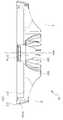
도 1은 본 발명의 일 실시 예에 따른 조명장치의 분해 사시도이다.
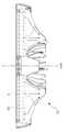
도 2는 본 발명의 일 실시 예에 따른 열확산 하우징을 나타내는 정단면도이다.
도 3은 도 2의 A를 확대하여 도시한 도면이다.
도 4는 도 2의 B를 확대하여 도시한 도면이다.
도 5 및 도 6은 본 발명의 일 실시 예에 따른 조명장치 내에서의 열의 흐름 상태를 도시한 도면이다.1 is an exploded perspective view of a lighting apparatus according to an embodiment of the present invention.
Figure 2 is a front sectional view showing a thermal diffusion housing according to an embodiment of the present invention.
3 is an enlarged view of a portion A of FIG. 2.
4 is an enlarged view of a portion B of FIG. 2.
5 and 6 are views showing a state of heat flow in the lighting apparatus according to an embodiment of the present invention.
이하, 첨부된 도면들을 참조하여 본 발명의 바람직한 실시 예를 상세히 설명할 것이다. 그러나 본 발명의 기술적 사상은 여기서 설명되는 실시 예에 한정되지 않고 다른 형태로 구체화 될 수도 있다. 오히려, 여기서 소개되는 실시 예는 개시된 내용이 철저하고 완전해질 수 있도록 그리고 당업자에게 본 발명의 사상이 충분히 전달될 수 있도록 하기 위해 제공되는 것이다.Hereinafter, exemplary embodiments of the present invention will be described in detail with reference to the accompanying drawings. However, the technical idea of the present invention is not limited to the exemplary embodiments described herein and may be embodied in other forms. Rather, the embodiments introduced herein are provided to ensure that the disclosed contents are thorough and complete, and that the spirit of the present invention can be sufficiently delivered to those skilled in the art.
본 명세서에서, 어떤 구성요소가 다른 구성요소 상에 있다고 언급되는 경우에 그것은 다른 구성요소 상에 직접 형성될 수 있거나 또는 그들 사이에 제 3의 구성요소가 개재될 수도 있다는 것을 의미한다. 또한, 도면들에 있어서, 막 및 영역들의 두께는 기술적 내용의 효과적인 설명을 위해 과장된 것이다.In the present specification, when a component is mentioned to be on another component, it means that it may be formed directly on the other component or a third component may be interposed therebetween. In addition, in the drawings, the thicknesses of films and regions are exaggerated for effective explanation of technical contents.
또한, 본 명세서의 다양한 실시 예들에서 제1, 제2, 제3 등의 용어가 다양한 구성요소들을 기술하기 위해서 사용되었지만, 이를 구성요소들이 이 같은 용어들에 의해서 한정되어서는 안 된다. 이들 용어들은 단지 어느 구성요소를 다른 구성요소와 구별시키기 위해서 사용되었을 뿐이다. 따라서 어느 한 실시 예에 제 1 구성요소로 언급된 것이 다른 실시 예에서는 제 2 구성요소로 언급될 수도 있다. 여기에 설명되고 예시되는, 각 실시 예는 그것의 상보적인 실시 예도 포함한다. 또한, 본 명세서에서 '및/또는'은 전후에 나열한 구성요소들 중 적어도 하나를 포함하는 의미로 사용되었다.In addition, in various embodiments of the present specification, terms such as first, second, and third are used to describe various components, but the components should not be limited by these terms. These terms are only used to distinguish one component from another. Therefore, what is referred to as a first component in one embodiment may be referred to as a second component in another embodiment. Each embodiment, described and illustrated herein, also includes its complementary embodiment. In addition, the term 'and / or' is used herein to include at least one of the components listed before and after.
명세서에서 단수의 표현은 문맥상 명백하게 다르게 뜻하지 않는 한 복수의 표현을 포함한다. 또한, "포함하다" 또는 "가지다" 등의 용어는 명세서상에 기재된 특징, 숫자, 단계, 구성요소 또는 이들을 조합한 것이 존재함을 지정하려는 것이지, 하나 또는 그 이상의 다른 특징이나 숫자, 단계, 구성요소 또는 이들을 조합한 것들의 존재 또는 부가 가능성을 배제하는 것으로 이해되어서는 안 된다. 또한, 본 명세서에서 "연결"은 복수의 구성요소를 간접적으로 연결하는 것, 및 직접적으로 연결하는 것을 모두 포함하는 의미로 사용된다.In the specification, the singular encompasses the plural unless the context clearly indicates otherwise. In addition, the terms "comprise" or "having" are intended to indicate that there is a feature, number, step, element, or combination thereof described in the specification, and one or more other features or numbers, steps, configurations It should not be understood to exclude the possibility of the presence or the addition of elements or combinations thereof. In addition, the term "connection" is used herein to mean both indirectly connecting a plurality of components, and directly connecting.
또한, 하기에서 본 발명을 설명함에 있어 관련된 공지 기능 또는 구성에 대한 구체적인 설명이 본 발명의 요지를 불필요하게 흐릴 수 있다고 판단되는 경우에는 그 상세한 설명은 생략할 것이다.In addition, in the following description of the present invention, if it is determined that a detailed description of a related known function or configuration may unnecessarily obscure the subject matter of the present invention, the detailed description thereof will be omitted.
도 1은 본 발명의 일 실시 예에 따른 조명장치의 분해 사시도이다.1 is an exploded perspective view of a lighting apparatus according to an embodiment of the present invention.
도 1을 참조하면, 조명장치는, 발광 모듈(20)이 전원(미도시)으로부터 전기적 에너지를 공급받아 빛 에너지로 전환하여 렌즈(10)를 통해 빛 에너지를 발산한다. 이 경우 조명장치는, 발광 모듈(20)에서 발생된 열을 열확산 하우징(30)을 거쳐 외부로 방열시킬 수 있다.Referring to FIG. 1, in the lighting apparatus, the
조명장치는, 발광 모듈(20)과 열확산 하우징(30)을 포함한다. 이 경우 조명장치는, 중심축(axis)을 하나의 축으로 하여 렌즈(10), 발광 모듈(20), 열확산 하우징(30)이 순차 적층된 구조일 수 있다.The lighting device includes a
발광 모듈(20)Light emitting module (20)
발광 모듈(20)은, 일면에 복수 개의 발광 소자(210)가 배치되어 면발광체를 이룰 수 있다. 발광 소자(210)는, 전원이 공급되어 발광 가능한 모든 종류의 발광 셀, 엘이디 소자, 엘이디 패키지, 엘이 칩, 엘이디 어레이 등을 포괄한다. 발광 모듈(20)은, 후술할 열확산 하우징(30)에 나사 결합되어 있으나, 결합 방법은 이에 한정되는 것은 아니다.In the
열확산 하우징(30)Thermal Diffusion Housing (30)
도 2는 본 발명의 일 실시 예에 따른 열확산 하우징(30)을 나타내는 정단면도이다.2 is a front sectional view showing a
도 1 및 도 2를 참조하면, 열확산 하우징(30)은, 발광 모듈(20)을 수용하여 지지하며, 발광 모듈(20)에서 발생한 열을 외부로 배출한다. 이러한 열확산 하우징(30)은, 발광 모듈(20)이 수용되도록 발광 모듈(20)의 타면을 복개할 수 있다. 열확산 하우징(30)은, 열확산 커버(310), 열확산 핀(320), 그리고 열확산 파이프(330)를 포함할 수 있다.1 and 2, the thermal diffusion housing 30 accommodates and supports the
열확산 하우징(30)은, 고온의 환경에서 사용하기 위하여 내열성이 좋은 금속성 재질로 이루어질 수 있다. 보다 구체적으로 금속성 재질은 경량의 열전도성이 좋은 Al, Mn 또는 이들의 합금 등으로 이루어질 수 있다.The
열확산 커버(310)Thermal Diffusion Cover (310)
열확산 커버(310)는, 발광 모듈(20)을 지지한다. 이러한 열확산 커버(310)는, 열확산 플레이트(311)와 측면 열확산 서포트(312)를 포함할 수 있다. 열확산 커버(310)는, 일면이 발광 모듈(20)과 면 접촉하고, 타면에 후술할 열확산 핀(320)와 열확산 파이프(330)가 형성될 수 있다.The
열확산 플레이트(311)Thermal Diffusion Plate (311)
열확산 플레이트(311)는, 발광 모듈(20)의 일면과 면 접촉되도록 발광 모듈(20)에 대응되는 크기와 형상을 가질 수 있다. 열확산 플레이트(311)는, 중심축(axis) 상에 제1 열확산 홀(311a)이 형성될 수 있다.The
제1 열확산 홀(311a)은, 중심축(axis) 방향으로의 스루 홀(through hole)일 수 있다. 열확산 플레이트(311)는, 발광 모듈(20)과 면접촉하여 발광 모듈(20)의 열을 전도 현상에 의해 후술할 열 확산 핀(320) 방향으로 방출할 수 있고, 대류 현상을 이용하여 제1 열확산 홀(311a)을 통해서도 발광 모듈(20)의 열을 외부로 방출할 수 있다.The first
측면 열확산 서포트(312)는, 열확산 커버(310)의 테두리 부분이다. 측면 열확산 서포트(312)는, 열확산 플레이트(311)의 외주연에 연장 형성되어 열확산 하우징(30)을 지지하는 벽체로 제공될 수 있다.The side
이러한 측면 열확산 서포트(312)는, 렌즈(10), 발광 모듈(20)의 순서대로 수용할 수 있다. 측면 열확산 서포트(312)는, 발광 모듈이 수용되도록 열확산 플레이트(311)의 가장자리를 따라 열확산 플레이트(311)의 두께 이상의 일정 두께로 마련될 수 있다. 측면 열확산 서포트(312)는, 측면 테두리를 따라 발광 모듈(20)을 지지하며 방열할 수 있다. 따라서 측면 열확산 서포트(312)의 두께(t2)는, 열확산 플레이트(t1)의 두께보다 두꺼울 수 있다.The side
측면 열확산 서포트(312)는, 중심축(axis) 방향으로 방사상 이격된 채 제2 열확산 홀(312a)이 복수 개가 형성될 수 있다. 제2 열확산 홀(312a)은, 측면 열확산 서포트(312)를 따라 일정한 간격으로 이격되어 방사상 형성된 통공일 수 있다.The lateral
도 3은 도 2의 A를 확대하여 도시한 도면이다.3 is an enlarged view of a portion A of FIG. 2.
도 2와 도 3을 참조하면, 제2 열확산 홀(312a)은, 대류 현상에 의한 공기 중의 방열 유속을 조절하기 위하여, 중심축(axis)에 대한 수직방향의 각 단면 형상들이 서로 다른 크기를 가질 수 있다. 제2 열확산 홀(312a)은, 유입구에서 유출구를 따라 통공의 단면이 달라질 수 있다. 제2 열확산 홀의 유입구 단면(s1)은, 중심축(axis)의 수직한 방향에서 볼 때 제2 열확산 홀의 유출구 단면(s2) 보다 클 수 있다. 즉, 제2 열확산 홀(312a)의 단면은, 제2 열확산 홀(312a)의 유입구 측에서 유출구 측 방향으로 갈수록 좁아지는 형상을 가질 수 있다.2 and 3, the second
이러한 제2 열확산 홀(312a)은, 유입구에서 유출구 측으로 갈수록 단면의 크기가 작아짐으로써 기압 차이를 유발할 수 있다. 이러한 기압 차이로 유입구에서 유출구로 갈수록 유속이 빨라져 열확산 하우징(30)의 방열 성능을 높일 수 있다.The second
열확산 핀(320)Thermal Diffusion Pins (320)
도 4는 도 2의 B를 확대하여 도시한 도면이다.4 is an enlarged view of a portion B of FIG. 2.
도 2와 도 4를 참조하면, 열확산 핀(320)은, 전도 현상을 이용해 순차로 접촉한 발광 모듈(20)로부터 열확산 플레이트(311)를 거쳐 외부로 열을 배출할 수 있다. 열확산 핀(320)은, 열확산 커버(310)의 타면에 평행한 방향으로 연장 형성될 수 있다. 즉 열확산 핀(320)은, 열확산 커버(310)를 기준으로 발광 모듈(20)과 대칭되게 위치할 수 있다. 또한 열확산 핀(320)은, 중심축(axis)을 중심으로 복수 개가 방사 형태로 마련될 수 있다. 이러한 열확산 핀(320)은, 발광 모듈(20)의 조도나 전력량, 사용처 등에 따라 그 개수를 임의로 조절할 수 있다.Referring to FIGS. 2 and 4, the
다시 도 2를 참조하면, 열확산 핀(320)은, 발광 모듈(20)에 인접할수록 넓은 면적을 가지고, 수직 방향으로 점차 멀어질수록 좁아지는 곡면 형태의 형상을 가질 수 있다. 보다 구체적으로 열확산 핀(320)은, 임의의 두께를 가지고, 곡면 형태의 모서리를 가질 수 있다. 열확산 핀(320)의 모서리는, 내주 모서리(R1)와 외주 모서리(R2)를 가질 수 있다. 내주 모서리(R1)는, 제1 곡률 반경을 가질 수 있다. 외주 모서리(R2)는, 제2 곡률 반경을 가질 수 있다. 이 경우 제2 곡률 반경은, 제1 곡률 반경보다 클 수 있다. 내주 모서리(R1)와 외주 모서리(R2)의 곡률 반경을 달리 함으로써, 열의 유동방향을 제어할 수 있다.Referring back to FIG. 2, the
이러한 열확산 핀(320)은, 외주 모서리(R2)의 곡률 반경을 내주 모서리(R1)의 곡률 반경보다 크게 함으로써, 전도 현상에 의해 취합된 열을 중심축(axis) 방향으로 집중되도록 흐름을 유도할 수 있다. 또한 열확산 핀(320)은, 큰 곡률 반경의 외주 모서리(R2)를 가짐으로써, 제2 열확산 홀(312a)을 통해 유입된 열이 외주 모서리(R2)를 따라 흐를 수 있도록 유도해 대류 현상에 의한 방열 성능을 높일 수 있다.The
열확산 파이프(330)Thermal Diffusion Pipes (330)
다시 도 1, 도 2와 도 4를 참조하면, 열확산 파이프(330)는, 중심축(axis) 방향으로 직경에 변화를 줌으로써, 제1 열확산 홀(311a)에서 유입된 열의 배출흐름을 빠르게 유도할 수 있다. 이러한 열확산 파이프(330)는, 열확산 커버(310)의 타면에 평행한 방향으로 연장 형성될 수 있다. 열확산 파이프(330)는, 중심축(axis)에 대하여 제1 열확산 홀(311a)과 연통되도록 마련될 수 있다. 열확산 파이프(330)는, 중심축(axis) 방향의 통공 형상일 수 있다. 열확산 파이프(330)는, 제1 열확산 홀(311a)과 연통되되, 대류 현상에 의한 공기 중의 방열 유속을 조절하기 위하여, 중심축(axis)의 수직한 방향에 대한 직경이 서로 달라질 수 있다. 열확산 파이프(330)는, 유입구 측에서 유출구 측 방향으로 갈수록 직경이 좁아지는 형상일 수 있다.Referring back to FIGS. 1, 2 and 4, the
열확산 파이프(330)는, 발광 모듈(20)에서 발생된 열이 제1 열확산 홀(311a)을 거쳐 대류 현상에 의해, 열확산 핀(320)의 내주 모서리(R1)를 따라 가이드 되도록 흐름을 유도할 수 있다. 이를 위하여 열확산 파이프(330)는, 열확산 핀(320)의 일부 모서리에 의해 둘러싸이도록 마련될 수 있다. 따라서 중심축(axis) 방향에서 바라볼 때, 열확산 파이프의 길이(h1)는, 열확산 핀의 높이(h2)보다 낮을 수 있다.The
또한, 열확산 파이프의 유입구 직경(r1)은, 대류 현상에 의하여 중앙부로 모아진 열을 외부로 빨리 확산시키기 위하여, 열확산 파이프의 유출구 직경(r2) 보다 2배 이상 큰 직경을 가질 수 있다. 열확산 파이프(330)의 유입구와 유출구의 직경이 2배 이상 차이남으로써, 발광 모듈(20)에서 발생한 열이 제1 열확산 홀(311a)과 열확산 파이프(330)를 거쳐 외부로 빠르게 배출되도록 하여, 열확산 흐름을 빠르게 유도할 수 있다.In addition, the inlet diameter r1 of the heat diffusion pipe may have a diameter that is at least two times larger than the outlet diameter r2 of the heat diffusion pipe in order to quickly diffuse the heat collected to the center portion by the convection phenomenon to the outside. Since the diameters of the inlet and outlet of the
도 5 및 도 6은 본 발명의 일 실시 예에 따른 조명장치 내에서의 열의 흐름 상태를 도시한 도면이다.5 and 6 are views showing a state of heat flow in the lighting apparatus according to an embodiment of the present invention.
도 5 및 도 6을 참조하면 조명장치 내에서의 방열 경로를 확인할 수 있다. 열은, 발광 모듈(20)에서 생성된 후 크게 전도 현상과 대류 현상에 의해 열확산 하우징(30)을 거쳐 외부로 방출될 수 있다.5 and 6, the heat dissipation path in the lighting apparatus may be confirmed. After the heat is generated in the
도 5에 예시된 대로 전도 현상에 의하여 열이 방출될 경우, 발광 모듈(20)에서 생성된 열은, 서로 맞닿아 적층된 열확산 플레이트(310)와 열확산 핀(320)를 거쳐 외부로 방출될 수 있다.When heat is released by the conduction phenomenon as illustrated in FIG. 5, heat generated in the
이 경우 열확산 핀(320)은 곡면 형태로 점차 좁아지는 형상을 가지므로, 발광 모듈(20)과 멀어질수록 내주 모서리(R1)와 외주 모서리(R2)의 끝단부 방향으로 열을 집중시켜 외부로 방출될 수 있다.In this case, since the
도 6에 예시된 대로 대류 현상에 의하여 열이 방출될 경우, 발광 모듈(20)에서 생성된 열은, 제1 열확산 홀(311a)과 열확산 파이프(330)를 거쳐 외부로 방출될 수 있다. 또한 제2 열확산 홀(312a)을 빠져 나온 열은 외주 모서리(R2)를 따라 중심축(axis) 방향으로 가이드 되어 외부로 방출될 수 있다.When heat is released by convection as illustrated in FIG. 6, heat generated in the
이 경우 대류 현상을 극대화하기 위하여, 제1열확산 홀(311a)과 열확산 파이프(330)는, 유입구에서 유출구로 통하는 각각의 직경의 크기를 서로 달리함으로써, 기압 차이에 의해 빠른 유속을 유도해 발광 모듈(20)에서 생성된 열을 빠르게 외부로 방출될 수 있다.In this case, in order to maximize the convection phenomenon, the first
이상, 본 발명을 바람직한 실시 예를 사용하여 상세히 설명하였으나, 본 발명의 범위는 특정 실시 예에 한정되는 것은 아니며, 첨부된 청구범위에 의하여 해석되어야 할 것이다. 또한, 이 기술분야에서 통상의 지식을 습득한 자라면, 본 발명의 범위에서 벗어나지 않으면서도 많은 수정과 변형이 가능함을 이해하여야 할 것이다.As mentioned above, although this invention was demonstrated in detail using the preferable embodiment, the scope of the present invention is not limited to a specific embodiment and should be interpreted by the attached Claim. In addition, those of ordinary skill in the art should understand that many modifications and variations are possible without departing from the scope of the present invention.
10 : 렌즈
20 : 발광 모듈210 : 발광 소자
30 : 열확산 하우징
310 : 열확산 커버311 : 열확산 플레이트
311a : 제1 열확산 홀312 : 측면 열확산 서포트
312a : 제2 열확산 홀
320 : 열확산 핀
330 : 열확산 파이프
t1 : 열확산 플레이트의 두께t2 : 측면 열확산 서포트의 두께
s1 : 제2 열확산 홀의 유입구 단면s2 : 제2 열확산 홀의 유출구 단면
R1 : 내주 모서리R2 : 외주 모서리
h1 : 열확산 파이프의 길이h2 : 열확산 핀의 높이
r1 : 열확산 파이프의 유입구 직경r2 : 열확산 파이프의 유출구 직경10: lens
20: light emitting module 210: light emitting element
30: thermal diffusion housing
310: thermal diffusion cover 311: thermal diffusion plate
311a: first heat diffusion hole 312: side heat diffusion support
312a: second thermal diffusion hole
320: thermal diffusion pin
330 thermal diffusion pipe
t1: thickness of thermal diffusion plate t2: thickness of side thermal diffusion support
s1: Inlet cross section of the second heat diffusion hole s2: Outlet cross section of the second heat diffusion hole
R1: inner edge R2: outer edge
h1: length of thermal diffusion pipe h2: height of thermal diffusion fin
r1: Inlet diameter of the heat diffusion pipe r2: Outlet diameter of the heat diffusion pipe
Claims (5)
Translated fromKorean상기 발광 모듈의 타면을 복개하는 열확산 하우징을 포함하고,
상기 열확산 하우징은,
중심축(axis) 상에 제1 열확산 홀이 형성된 열확산 플레이트와, 상기 열확산 플레이트의 외주연에 연장 형성되어 가장자리를 따라 복수 개의 제2 열확산 홀이 형성된 측면 열확산 서포트를 가지는 열확산 커버;
상기 열확산 커버의 타면에 평행한 방향으로 연장 형성되되, 상기 중심축(axis)을 중심으로 방사 형태로 마련된 복수의 열확산 핀; 및
상기 열확산 커버의 타면에 평행한 방향으로 연장 형성되되, 상기 중심축(axis)에 대하여 상기 제1 열확산 홀과 연통되도록 마련된 열확산 파이프를 포함하는, 조명장치.
A light emitting module in which a plurality of light emitting elements are disposed on one surface to form a surface light emitting body; And
A thermal diffusion housing covering the other surface of the light emitting module,
The thermal diffusion housing,
A heat spreading cover having a heat spreading plate having a first heat spreading hole formed on a central axis and a side heat spreading support extending from an outer circumference of the heat spreading plate and having a plurality of second heat spreading holes formed along an edge thereof;
A plurality of thermal diffusion fins extending in a direction parallel to the other surface of the thermal diffusion cover, the thermal diffusion fins being provided radially about the central axis; And
And a heat diffusion pipe extending in a direction parallel to the other surface of the heat diffusion cover and provided to communicate with the first heat diffusion hole with respect to the central axis.
상기 제2 열확산 홀의 단면은 유입구 측에서 유출구 측 방향으로 갈수록 좁아지는 형상을 가지는, 조명장치.
The method of claim 1,
The cross section of the second heat diffusion hole has a shape that becomes narrower toward the outlet side from the inlet side.
상기 열확산 핀의 일부 모서리는 상기 중심축(axis) 방향에서 곡면으로 형성되되,
상기 열확산 핀의 일부 모서리는,
제1 곡률 반경을 가지는 내주 모서리; 및
상기 제1 곡률 반경보다 큰 제2 곡률 반경을 가지는 외주 모서리인, 조명장치.
The method of claim 1,
Some edges of the heat diffusion fin are formed in a curved surface in the direction of the central axis,
Some corners of the thermal diffusion fins,
An inner circumferential edge having a first radius of curvature; And
And a peripheral edge having a second radius of curvature greater than the first radius of curvature.
상기 열확산 파이프는 상기 열확산 핀의 일부 모서리에 의해 둘러싸이도록 마련된, 조명장치.
The method of claim 1,
And the thermal diffusion pipe is provided to be surrounded by some edge of the thermal diffusion fin.
상기 열확산 파이프의 유입구는 상기 열확산 파이프의 유출구의 직경 보다 2배 이상의 큰 직경을 가지는, 조명장치.The method of claim 1,
And an inlet of the heat diffusion pipe has a diameter that is at least two times larger than the diameter of the outlet of the heat diffusion pipe.
Priority Applications (1)
| Application Number | Priority Date | Filing Date | Title |
|---|---|---|---|
| KR1020180061846AKR102069514B1 (en) | 2018-05-30 | 2018-05-30 | Lighting apparatus |
Applications Claiming Priority (1)
| Application Number | Priority Date | Filing Date | Title |
|---|---|---|---|
| KR1020180061846AKR102069514B1 (en) | 2018-05-30 | 2018-05-30 | Lighting apparatus |
Publications (2)
| Publication Number | Publication Date |
|---|---|
| KR20190136306Atrue KR20190136306A (en) | 2019-12-10 |
| KR102069514B1 KR102069514B1 (en) | 2020-01-23 |
Family
ID=69002497
Family Applications (1)
| Application Number | Title | Priority Date | Filing Date |
|---|---|---|---|
| KR1020180061846AActiveKR102069514B1 (en) | 2018-05-30 | 2018-05-30 | Lighting apparatus |
Country Status (1)
| Country | Link |
|---|---|
| KR (1) | KR102069514B1 (en) |
Citations (7)
| Publication number | Priority date | Publication date | Assignee | Title |
|---|---|---|---|---|
| KR101125747B1 (en)* | 2011-10-28 | 2012-03-27 | 주식회사 금영 | Led lamp |
| KR101402916B1 (en)* | 2014-03-20 | 2014-06-30 | 주식회사 디에스이 | LED room lamp with a air circulation cooling |
| KR101421584B1 (en)* | 2013-04-10 | 2014-07-22 | 미미라이팅주식회사 | LED Lighting Apparatus For Radiation Area |
| KR101418073B1 (en)* | 2012-12-14 | 2014-08-05 | 주식회사 포스코티엠씨 | Radiation fin having O-ring groove and hole and, LED illumination lamp having the same |
| KR20150095295A (en)* | 2014-02-13 | 2015-08-21 | 동부라이텍 주식회사 | Heat sink apparatus |
| KR101663176B1 (en)* | 2016-03-31 | 2016-10-06 | 주식회사 쎄미라이팅 | High temperature led lighting apparatus |
| KR101799732B1 (en)* | 2017-05-11 | 2017-11-20 | 임정희 | Air cooled heat radiation block for the led |
- 2018
- 2018-05-30KRKR1020180061846Apatent/KR102069514B1/enactiveActive
Patent Citations (7)
| Publication number | Priority date | Publication date | Assignee | Title |
|---|---|---|---|---|
| KR101125747B1 (en)* | 2011-10-28 | 2012-03-27 | 주식회사 금영 | Led lamp |
| KR101418073B1 (en)* | 2012-12-14 | 2014-08-05 | 주식회사 포스코티엠씨 | Radiation fin having O-ring groove and hole and, LED illumination lamp having the same |
| KR101421584B1 (en)* | 2013-04-10 | 2014-07-22 | 미미라이팅주식회사 | LED Lighting Apparatus For Radiation Area |
| KR20150095295A (en)* | 2014-02-13 | 2015-08-21 | 동부라이텍 주식회사 | Heat sink apparatus |
| KR101402916B1 (en)* | 2014-03-20 | 2014-06-30 | 주식회사 디에스이 | LED room lamp with a air circulation cooling |
| KR101663176B1 (en)* | 2016-03-31 | 2016-10-06 | 주식회사 쎄미라이팅 | High temperature led lighting apparatus |
| KR101799732B1 (en)* | 2017-05-11 | 2017-11-20 | 임정희 | Air cooled heat radiation block for the led |
Also Published As
| Publication number | Publication date |
|---|---|
| KR102069514B1 (en) | 2020-01-23 |
Similar Documents
| Publication | Publication Date | Title |
|---|---|---|
| US7847471B2 (en) | LED lamp | |
| US7434964B1 (en) | LED lamp with a heat sink assembly | |
| US9429295B2 (en) | Lighting apparatus | |
| KR20130081669A (en) | Electric luminous body having heat dissipater with axial and radial air aperture | |
| US20080007954A1 (en) | Heat-Dissipating Structure For LED Lamp | |
| EP2295853B1 (en) | Light Emitting Diode Lamp Structure | |
| JP2011513918A (en) | Heat removal system and method for light emitting diode lighting equipment | |
| CA2790112A1 (en) | Led lighting apparatus | |
| KR101194029B1 (en) | Heatsink for LED light | |
| US20140153225A1 (en) | Led lighting device | |
| KR102054750B1 (en) | LED Lighting Apparatus | |
| KR101938466B1 (en) | Heat-dissipation device of led | |
| US20130163247A1 (en) | Lamp base and lamp having the same | |
| US20190360682A1 (en) | Lighting fixture for vehicle | |
| KR100966599B1 (en) | Led lighting lamp | |
| KR102069514B1 (en) | Lighting apparatus | |
| US20170051908A1 (en) | Heat dissipation structure for led and led lighting lamp including the same | |
| RU2619912C2 (en) | Led lighting device | |
| KR101318434B1 (en) | Led lighting apparatus | |
| TW200912187A (en) | LED lamp with a heat sink | |
| KR102315636B1 (en) | Heat dissipation device having lateral-spreading heat dissipating and shunting heat conductive structure | |
| KR101615703B1 (en) | Led lamp for improving heat radiation | |
| KR20140103665A (en) | Heat sink | |
| KR101181334B1 (en) | Led lighting apparatus with a converter | |
| US20140029255A1 (en) | Cooling system and lighting device comprised thereof |
Legal Events
| Date | Code | Title | Description |
|---|---|---|---|
| A201 | Request for examination | ||
| PA0109 | Patent application | Patent event code:PA01091R01D Comment text:Patent Application Patent event date:20180530 | |
| PA0201 | Request for examination | ||
| E902 | Notification of reason for refusal | ||
| PE0902 | Notice of grounds for rejection | Comment text:Notification of reason for refusal Patent event date:20190627 Patent event code:PE09021S01D | |
| E701 | Decision to grant or registration of patent right | ||
| PE0701 | Decision of registration | Patent event code:PE07011S01D Comment text:Decision to Grant Registration Patent event date:20191204 | |
| PG1501 | Laying open of application | ||
| PR0701 | Registration of establishment | Comment text:Registration of Establishment Patent event date:20200117 Patent event code:PR07011E01D | |
| PR1002 | Payment of registration fee | Payment date:20200117 End annual number:3 Start annual number:1 | |
| PG1601 | Publication of registration | ||
| PR1001 | Payment of annual fee | Payment date:20230717 Start annual number:4 End annual number:4 | |
| PR1001 | Payment of annual fee | Payment date:20240117 Start annual number:5 End annual number:5 |