KR20190136052A - Multi-layered structure and its manufacturing method - Google Patents
Multi-layered structure and its manufacturing methodDownload PDFInfo
- Publication number
- KR20190136052A KR20190136052AKR1020197032384AKR20197032384AKR20190136052AKR 20190136052 AKR20190136052 AKR 20190136052AKR 1020197032384 AKR1020197032384 AKR 1020197032384AKR 20197032384 AKR20197032384 AKR 20197032384AKR 20190136052 AKR20190136052 AKR 20190136052A
- Authority
- KR
- South Korea
- Prior art keywords
- glass
- layer
- overlay
- major surface
- less
- Prior art date
- Legal status (The legal status is an assumption and is not a legal conclusion. Google has not performed a legal analysis and makes no representation as to the accuracy of the status listed.)
- Granted
Links
Images


Classifications
- C—CHEMISTRY; METALLURGY
- C03—GLASS; MINERAL OR SLAG WOOL
- C03C—CHEMICAL COMPOSITION OF GLASSES, GLAZES OR VITREOUS ENAMELS; SURFACE TREATMENT OF GLASS; SURFACE TREATMENT OF FIBRES OR FILAMENTS MADE FROM GLASS, MINERALS OR SLAGS; JOINING GLASS TO GLASS OR OTHER MATERIALS
- C03C15/00—Surface treatment of glass, not in the form of fibres or filaments, by etching
- B—PERFORMING OPERATIONS; TRANSPORTING
- B32—LAYERED PRODUCTS
- B32B—LAYERED PRODUCTS, i.e. PRODUCTS BUILT-UP OF STRATA OF FLAT OR NON-FLAT, e.g. CELLULAR OR HONEYCOMB, FORM
- B32B33/00—Layered products characterised by particular properties or particular surface features, e.g. particular surface coatings; Layered products designed for particular purposes not covered by another single class
- B—PERFORMING OPERATIONS; TRANSPORTING
- B32—LAYERED PRODUCTS
- B32B—LAYERED PRODUCTS, i.e. PRODUCTS BUILT-UP OF STRATA OF FLAT OR NON-FLAT, e.g. CELLULAR OR HONEYCOMB, FORM
- B32B17/00—Layered products essentially comprising sheet glass, or glass, slag, or like fibres
- B32B17/06—Layered products essentially comprising sheet glass, or glass, slag, or like fibres comprising glass as the main or only constituent of a layer, next to another layer of a specific material
- B32B17/10—Layered products essentially comprising sheet glass, or glass, slag, or like fibres comprising glass as the main or only constituent of a layer, next to another layer of a specific material of synthetic resin
- B32B17/10005—Layered products essentially comprising sheet glass, or glass, slag, or like fibres comprising glass as the main or only constituent of a layer, next to another layer of a specific material of synthetic resin laminated safety glass or glazing
- B32B17/10009—Layered products essentially comprising sheet glass, or glass, slag, or like fibres comprising glass as the main or only constituent of a layer, next to another layer of a specific material of synthetic resin laminated safety glass or glazing characterized by the number, the constitution or treatment of glass sheets
- B32B17/10064—Layered products essentially comprising sheet glass, or glass, slag, or like fibres comprising glass as the main or only constituent of a layer, next to another layer of a specific material of synthetic resin laminated safety glass or glazing characterized by the number, the constitution or treatment of glass sheets comprising at least two glass sheets, only one of which being an outer layer
- B—PERFORMING OPERATIONS; TRANSPORTING
- B32—LAYERED PRODUCTS
- B32B—LAYERED PRODUCTS, i.e. PRODUCTS BUILT-UP OF STRATA OF FLAT OR NON-FLAT, e.g. CELLULAR OR HONEYCOMB, FORM
- B32B17/00—Layered products essentially comprising sheet glass, or glass, slag, or like fibres
- B32B17/06—Layered products essentially comprising sheet glass, or glass, slag, or like fibres comprising glass as the main or only constituent of a layer, next to another layer of a specific material
- B32B17/10—Layered products essentially comprising sheet glass, or glass, slag, or like fibres comprising glass as the main or only constituent of a layer, next to another layer of a specific material of synthetic resin
- B32B17/10005—Layered products essentially comprising sheet glass, or glass, slag, or like fibres comprising glass as the main or only constituent of a layer, next to another layer of a specific material of synthetic resin laminated safety glass or glazing
- B32B17/10009—Layered products essentially comprising sheet glass, or glass, slag, or like fibres comprising glass as the main or only constituent of a layer, next to another layer of a specific material of synthetic resin laminated safety glass or glazing characterized by the number, the constitution or treatment of glass sheets
- B32B17/10128—Treatment of at least one glass sheet
- B32B17/10137—Chemical strengthening
- B—PERFORMING OPERATIONS; TRANSPORTING
- B32—LAYERED PRODUCTS
- B32B—LAYERED PRODUCTS, i.e. PRODUCTS BUILT-UP OF STRATA OF FLAT OR NON-FLAT, e.g. CELLULAR OR HONEYCOMB, FORM
- B32B17/00—Layered products essentially comprising sheet glass, or glass, slag, or like fibres
- B32B17/06—Layered products essentially comprising sheet glass, or glass, slag, or like fibres comprising glass as the main or only constituent of a layer, next to another layer of a specific material
- B32B17/10—Layered products essentially comprising sheet glass, or glass, slag, or like fibres comprising glass as the main or only constituent of a layer, next to another layer of a specific material of synthetic resin
- B32B17/10005—Layered products essentially comprising sheet glass, or glass, slag, or like fibres comprising glass as the main or only constituent of a layer, next to another layer of a specific material of synthetic resin laminated safety glass or glazing
- B32B17/10009—Layered products essentially comprising sheet glass, or glass, slag, or like fibres comprising glass as the main or only constituent of a layer, next to another layer of a specific material of synthetic resin laminated safety glass or glazing characterized by the number, the constitution or treatment of glass sheets
- B32B17/10128—Treatment of at least one glass sheet
- B32B17/10146—Face treatment, e.g. etching, grinding or sand blasting
- B—PERFORMING OPERATIONS; TRANSPORTING
- B32—LAYERED PRODUCTS
- B32B—LAYERED PRODUCTS, i.e. PRODUCTS BUILT-UP OF STRATA OF FLAT OR NON-FLAT, e.g. CELLULAR OR HONEYCOMB, FORM
- B32B17/00—Layered products essentially comprising sheet glass, or glass, slag, or like fibres
- B32B17/06—Layered products essentially comprising sheet glass, or glass, slag, or like fibres comprising glass as the main or only constituent of a layer, next to another layer of a specific material
- B32B17/10—Layered products essentially comprising sheet glass, or glass, slag, or like fibres comprising glass as the main or only constituent of a layer, next to another layer of a specific material of synthetic resin
- B32B17/10005—Layered products essentially comprising sheet glass, or glass, slag, or like fibres comprising glass as the main or only constituent of a layer, next to another layer of a specific material of synthetic resin laminated safety glass or glazing
- B32B17/10807—Making laminated safety glass or glazing; Apparatus therefor
- B32B17/10899—Making laminated safety glass or glazing; Apparatus therefor by introducing interlayers of synthetic resin
- B—PERFORMING OPERATIONS; TRANSPORTING
- B32—LAYERED PRODUCTS
- B32B—LAYERED PRODUCTS, i.e. PRODUCTS BUILT-UP OF STRATA OF FLAT OR NON-FLAT, e.g. CELLULAR OR HONEYCOMB, FORM
- B32B37/00—Methods or apparatus for laminating, e.g. by curing or by ultrasonic bonding
- B32B37/12—Methods or apparatus for laminating, e.g. by curing or by ultrasonic bonding characterised by using adhesives
- B—PERFORMING OPERATIONS; TRANSPORTING
- B32—LAYERED PRODUCTS
- B32B—LAYERED PRODUCTS, i.e. PRODUCTS BUILT-UP OF STRATA OF FLAT OR NON-FLAT, e.g. CELLULAR OR HONEYCOMB, FORM
- B32B37/00—Methods or apparatus for laminating, e.g. by curing or by ultrasonic bonding
- B32B37/14—Methods or apparatus for laminating, e.g. by curing or by ultrasonic bonding characterised by the properties of the layers
- B32B37/16—Methods or apparatus for laminating, e.g. by curing or by ultrasonic bonding characterised by the properties of the layers with all layers existing as coherent layers before laminating
- B32B37/18—Methods or apparatus for laminating, e.g. by curing or by ultrasonic bonding characterised by the properties of the layers with all layers existing as coherent layers before laminating involving the assembly of discrete sheets or panels only
- B32B37/182—Methods or apparatus for laminating, e.g. by curing or by ultrasonic bonding characterised by the properties of the layers with all layers existing as coherent layers before laminating involving the assembly of discrete sheets or panels only one or more of the layers being plastic
- B—PERFORMING OPERATIONS; TRANSPORTING
- B32—LAYERED PRODUCTS
- B32B—LAYERED PRODUCTS, i.e. PRODUCTS BUILT-UP OF STRATA OF FLAT OR NON-FLAT, e.g. CELLULAR OR HONEYCOMB, FORM
- B32B7/00—Layered products characterised by the relation between layers; Layered products characterised by the relative orientation of features between layers, or by the relative values of a measurable parameter between layers, i.e. products comprising layers having different physical, chemical or physicochemical properties; Layered products characterised by the interconnection of layers
- B32B7/04—Interconnection of layers
- B32B7/12—Interconnection of layers using interposed adhesives or interposed materials with bonding properties
- C—CHEMISTRY; METALLURGY
- C03—GLASS; MINERAL OR SLAG WOOL
- C03C—CHEMICAL COMPOSITION OF GLASSES, GLAZES OR VITREOUS ENAMELS; SURFACE TREATMENT OF GLASS; SURFACE TREATMENT OF FIBRES OR FILAMENTS MADE FROM GLASS, MINERALS OR SLAGS; JOINING GLASS TO GLASS OR OTHER MATERIALS
- C03C21/00—Treatment of glass, not in the form of fibres or filaments, by diffusing ions or metals in the surface
- C03C21/001—Treatment of glass, not in the form of fibres or filaments, by diffusing ions or metals in the surface in liquid phase, e.g. molten salts, solutions
- C03C21/002—Treatment of glass, not in the form of fibres or filaments, by diffusing ions or metals in the surface in liquid phase, e.g. molten salts, solutions to perform ion-exchange between alkali ions
- C—CHEMISTRY; METALLURGY
- C03—GLASS; MINERAL OR SLAG WOOL
- C03C—CHEMICAL COMPOSITION OF GLASSES, GLAZES OR VITREOUS ENAMELS; SURFACE TREATMENT OF GLASS; SURFACE TREATMENT OF FIBRES OR FILAMENTS MADE FROM GLASS, MINERALS OR SLAGS; JOINING GLASS TO GLASS OR OTHER MATERIALS
- C03C27/00—Joining pieces of glass to pieces of other inorganic material; Joining glass to glass other than by fusing
- C03C27/06—Joining glass to glass by processes other than fusing
- C03C27/10—Joining glass to glass by processes other than fusing with the aid of adhesive specially adapted for that purpose
- H—ELECTRICITY
- H04—ELECTRIC COMMUNICATION TECHNIQUE
- H04M—TELEPHONIC COMMUNICATION
- H04M1/00—Substation equipment, e.g. for use by subscribers
- H04M1/02—Constructional features of telephone sets
- H04M1/0202—Portable telephone sets, e.g. cordless phones, mobile phones or bar type handsets
- H04M1/026—Details of the structure or mounting of specific components
- H04M1/0266—Details of the structure or mounting of specific components for a display module assembly
- H—ELECTRICITY
- H05—ELECTRIC TECHNIQUES NOT OTHERWISE PROVIDED FOR
- H05K—PRINTED CIRCUITS; CASINGS OR CONSTRUCTIONAL DETAILS OF ELECTRIC APPARATUS; MANUFACTURE OF ASSEMBLAGES OF ELECTRICAL COMPONENTS
- H05K1/00—Printed circuits
- H05K1/02—Details
- H05K1/0296—Conductive pattern lay-out details not covered by sub groups H05K1/02 - H05K1/0295
- B—PERFORMING OPERATIONS; TRANSPORTING
- B32—LAYERED PRODUCTS
- B32B—LAYERED PRODUCTS, i.e. PRODUCTS BUILT-UP OF STRATA OF FLAT OR NON-FLAT, e.g. CELLULAR OR HONEYCOMB, FORM
- B32B2307/00—Properties of the layers or laminate
- B32B2307/20—Properties of the layers or laminate having particular electrical or magnetic properties, e.g. piezoelectric
- B32B2307/202—Conductive
- B—PERFORMING OPERATIONS; TRANSPORTING
- B32—LAYERED PRODUCTS
- B32B—LAYERED PRODUCTS, i.e. PRODUCTS BUILT-UP OF STRATA OF FLAT OR NON-FLAT, e.g. CELLULAR OR HONEYCOMB, FORM
- B32B2307/00—Properties of the layers or laminate
- B32B2307/20—Properties of the layers or laminate having particular electrical or magnetic properties, e.g. piezoelectric
- B32B2307/204—Di-electric
- B—PERFORMING OPERATIONS; TRANSPORTING
- B32—LAYERED PRODUCTS
- B32B—LAYERED PRODUCTS, i.e. PRODUCTS BUILT-UP OF STRATA OF FLAT OR NON-FLAT, e.g. CELLULAR OR HONEYCOMB, FORM
- B32B2307/00—Properties of the layers or laminate
- B32B2307/40—Properties of the layers or laminate having particular optical properties
- B32B2307/412—Transparent
- B—PERFORMING OPERATIONS; TRANSPORTING
- B32—LAYERED PRODUCTS
- B32B—LAYERED PRODUCTS, i.e. PRODUCTS BUILT-UP OF STRATA OF FLAT OR NON-FLAT, e.g. CELLULAR OR HONEYCOMB, FORM
- B32B2307/00—Properties of the layers or laminate
- B32B2307/50—Properties of the layers or laminate having particular mechanical properties
- B32B2307/554—Wear resistance
- B—PERFORMING OPERATIONS; TRANSPORTING
- B32—LAYERED PRODUCTS
- B32B—LAYERED PRODUCTS, i.e. PRODUCTS BUILT-UP OF STRATA OF FLAT OR NON-FLAT, e.g. CELLULAR OR HONEYCOMB, FORM
- B32B2307/00—Properties of the layers or laminate
- B32B2307/50—Properties of the layers or laminate having particular mechanical properties
- B32B2307/558—Impact strength, toughness
- B—PERFORMING OPERATIONS; TRANSPORTING
- B32—LAYERED PRODUCTS
- B32B—LAYERED PRODUCTS, i.e. PRODUCTS BUILT-UP OF STRATA OF FLAT OR NON-FLAT, e.g. CELLULAR OR HONEYCOMB, FORM
- B32B2315/00—Other materials containing non-metallic inorganic compounds not provided for in groups B32B2311/00 - B32B2313/04
- B32B2315/08—Glass
- B—PERFORMING OPERATIONS; TRANSPORTING
- B32—LAYERED PRODUCTS
- B32B—LAYERED PRODUCTS, i.e. PRODUCTS BUILT-UP OF STRATA OF FLAT OR NON-FLAT, e.g. CELLULAR OR HONEYCOMB, FORM
- B32B2457/00—Electrical equipment
- B32B2457/20—Displays, e.g. liquid crystal displays, plasma displays
- C—CHEMISTRY; METALLURGY
- C03—GLASS; MINERAL OR SLAG WOOL
- C03C—CHEMICAL COMPOSITION OF GLASSES, GLAZES OR VITREOUS ENAMELS; SURFACE TREATMENT OF GLASS; SURFACE TREATMENT OF FIBRES OR FILAMENTS MADE FROM GLASS, MINERALS OR SLAGS; JOINING GLASS TO GLASS OR OTHER MATERIALS
- C03C2218/00—Methods for coating glass
- C03C2218/10—Deposition methods
- H—ELECTRICITY
- H05—ELECTRIC TECHNIQUES NOT OTHERWISE PROVIDED FOR
- H05K—PRINTED CIRCUITS; CASINGS OR CONSTRUCTIONAL DETAILS OF ELECTRIC APPARATUS; MANUFACTURE OF ASSEMBLAGES OF ELECTRICAL COMPONENTS
- H05K2201/00—Indexing scheme relating to printed circuits covered by H05K1/00
- H05K2201/01—Dielectrics
- H05K2201/0137—Materials
- H05K2201/017—Glass ceramic coating, e.g. formed on inorganic substrate
- H—ELECTRICITY
- H05—ELECTRIC TECHNIQUES NOT OTHERWISE PROVIDED FOR
- H05K—PRINTED CIRCUITS; CASINGS OR CONSTRUCTIONAL DETAILS OF ELECTRIC APPARATUS; MANUFACTURE OF ASSEMBLAGES OF ELECTRICAL COMPONENTS
- H05K2201/00—Indexing scheme relating to printed circuits covered by H05K1/00
- H05K2201/01—Dielectrics
- H05K2201/0183—Dielectric layers
- H05K2201/0195—Dielectric or adhesive layers comprising a plurality of layers, e.g. in a multilayer structure
- H—ELECTRICITY
- H05—ELECTRIC TECHNIQUES NOT OTHERWISE PROVIDED FOR
- H05K—PRINTED CIRCUITS; CASINGS OR CONSTRUCTIONAL DETAILS OF ELECTRIC APPARATUS; MANUFACTURE OF ASSEMBLAGES OF ELECTRICAL COMPONENTS
- H05K5/00—Casings, cabinets or drawers for electric apparatus
- H05K5/02—Details
- H05K5/03—Covers
Landscapes
- Chemical & Material Sciences (AREA)
- Engineering & Computer Science (AREA)
- General Chemical & Material Sciences (AREA)
- Chemical Kinetics & Catalysis (AREA)
- Materials Engineering (AREA)
- Geochemistry & Mineralogy (AREA)
- Life Sciences & Earth Sciences (AREA)
- Organic Chemistry (AREA)
- Ceramic Engineering (AREA)
- Microelectronics & Electronic Packaging (AREA)
- Signal Processing (AREA)
- Surface Treatment Of Glass (AREA)
- Laminated Bodies (AREA)
- Joining Of Glass To Other Materials (AREA)
- Devices For Indicating Variable Information By Combining Individual Elements (AREA)
Abstract
Translated fromKoreanDescription
Translated fromKorean본 출원은 2017년 4월 4일자에 출원된 미국 가출원번호 제62/481,387호의 우선권을 청구하며, 상기 문헌의 내용은 그 전체가 참고로서 이후 자세하게 설명되는 바와 같이 본원에 포함된다.This application claims the priority of U.S. Provisional Application No. 62 / 481,387, filed April 4, 2017, the contents of which are incorporated herein by reference in their entirety.
본 기재의 예시적인 구현예는 다층 구조체 및 그 제조방법에 관한 것이다. 좀 더 구체적으로, 본 기재의 예시적인 구현예는 다층 구조체에서 고 강도, 초-박 유리 시트, 유리 물질의 유리 오버레이를 포함하는 보호 유리 시스템, 및 고 강도, 초-박 유리 시트를 갖는 다층 구조체의 제조방법에 관한 것이다.Exemplary embodiments of the present disclosure relate to multilayer structures and methods of making the same. More specifically, exemplary embodiments of the present disclosure provide a multilayer structure having a high strength, ultra-thin glass sheet in a multilayer structure, a protective glass system comprising a glass overlay of glass material, and a high strength, ultra-thin glass sheet. It relates to a manufacturing method of.
센서를 갖는 디스플레이와 같은 전자 장치용 커버는 다양한 장치에 사용될 수 있다. 일반적으로, 커버 물질을 선택하는데 고려하기 위한 성질 또는 인자들은 두께, 유전 상수, 비용 및 내구성을 포함할 수 있다. 예를 들어, 센서 커버는 바람직하지 않거나 또는 수용가능하지 않은 수준으로 신호-대-잡음 비를 감소시킬 수 있다. 많은 커버는 도 1에 나타낸 바와 같은 두꺼운 폴리머 물질 또는 사파이어와 같은 값비싼 물질로 이루어질 수 있다. 폴리머 오버레이는 인-서비스를 빠르게 손상하고 신호를 억제하며, 오측(false reading)을 제공할 수 있는 한편 사파이어는 너무 고비용일 수 있다.Covers for electronic devices such as displays with sensors can be used in a variety of devices. In general, properties or factors to consider in selecting a cover material may include thickness, dielectric constant, cost, and durability. For example, the sensor cover can reduce the signal-to-noise ratio to an undesirable or unacceptable level. Many covers may be made of a thick polymeric material as shown in FIG. 1 or an expensive material such as sapphire. Polymer overlays can quickly damage in-service, suppress signals, and provide false reading while sapphire can be too expensive.
도 1은 기판 층(20) 상에 배치된 전도체(16) 및 약 10 마이크로미터의 폴리머(28)로 커버된 베이스 층(24)을 갖는 센서(12)의 다이어그램이며, 40 내지 50 마이크로미터의 폴리머-계 색상 및 하드 코팅(32) 층이 배치된다. 신호-대-잡음 비 (SNR)에 의해 측정된 바에 따라 센서(12)의 민감도가 커버 두께에 따라 크게 좌우될 수 있으므로 상기 커버의 낮은 전체 두께가 바람직하다. 상기 SNR은 커버의 코팅 스택의 마이크로미터 당 대략 0.7 dB 감소한다. 커버에 대한 종래의 접근은 도 1에 나타낸 바와 같은 두꺼운 폴리머 계 코팅을 적용하는 것이며, 여기서 센서 어레이는 약 60 마이크로미터 두께의 폴리머 코팅에 의해 커버될 수 있다. 상기 폴리머 코팅은 하나 이상의 층을 포함할 수 있다.1 is a diagram of a
본 배경기술 부분에서 개시된 상기 정보는 단지 본 기재의 배경을 좀 더 잘 이해하기 위한 것으로, 종래 기술의 부분을 형성하지 않는 정보를 함유할 수 있으며, 종래 기술이 당업자에게 제안하지 않는 정보를 함유할 수 있다.The information disclosed in this Background section is merely for a better understanding of the background of the present disclosure and may contain information that does not form part of the prior art, and may contain information that the prior art does not suggest to those skilled in the art. Can be.
본 기재의 예시적인 구현예는 초-박 및 높은 펑크 저항성 유리 시트의 커버를 갖는 다층 구조체를 제공한다.Exemplary embodiments of the present disclosure provide a multilayer structure having a cover of ultra-thin and high puncture resistant glass sheet.
본 기재의 예시적인 구현예는 또한 보호 유리 시스템을 제공한다.Exemplary embodiments of the present disclosure also provide a protective glass system.
본 기재의 예시적인 구현예는 또한 초-박 및 높은 펑크 저항성 유리 시트의 커버를 갖는 다층 구조체의 제조방법을 제공한다.Exemplary embodiments of the present disclosure also provide a method of making a multilayer structure having a cover of ultra-thin and high puncture resistant glass sheet.
본 기재의 추가적인 이점은 다음의 설명에서 설명될 것이며, 부분적으로는 본 설명으로부터 명백해지거나 또는 본 기재의 실시에 의해 습득될 수 있을 것이다.Additional advantages of the present disclosure will be set forth in the description which follows, and in part will be apparent from the description, or may be learned by practice of the disclosure.
예시적인 구현예는 다층 구조체를 개시하며, 상기 다층 구조체는 유리 시트, 라미네이션 층, 및 기판 층을 포함하며, 여기서 상기 유리 시트 및 기판 층은 라미네이션 층을 통해 함께 라미네이트된다. 상기 유리 시트는 250 마이크로미터 미만의 두께이며, 상기 유리 시트는 제1 및 제2의 템퍼 표면을 포함하며, 적어도 상기 제1의 템퍼 표면은 적어도 5 마이크로미터의 깊이를 갖는 표면 압축층 및 적어도 200 MPa의 표면 압축 응력을 포함한다. 상기 다층 구조체의 유리 시트의 펑크 계수, Pf는 B10 (고장 확률 분포의 10번째 백분위수)에서 적어도 3000 N/mm2이다. 상기 펑크 계수는 상기 유리 시트의 두께 제곱에 대한 고장에서의 펑크 하중의 비이다. 여기서, 상기 펑크 계수는 상기 유리 시트의 적어도 하나의 템퍼 표면에 걸쳐 중심에 있는 1.5 mm의 직경 구형 세그먼트 팁 및 초당 약 30 뉴턴의 속도로 선형적으로 증가하는 하중에 의해 측정된다.An exemplary embodiment discloses a multilayer structure, wherein the multilayer structure comprises a glass sheet, a lamination layer, and a substrate layer, wherein the glass sheet and the substrate layer are laminated together through a lamination layer. The glass sheet is less than 250 micrometers thick, the glass sheet includes first and second tempered surfaces, and at least the first tempered surface is at least 200 and a surface compression layer having a depth of at least 5 micrometers. Surface compressive stress of MPa. The puncture coefficient, Pf, of the glass sheet of the multilayer structure is at least 3000 N / mm2 at B10 (10th percentile of failure probability distribution). The puncture coefficient is the ratio of the puncture load at failure to the square of the thickness of the glass sheet. Here, the puncture coefficient is measured by a linearly increasing load at a rate of about 30 Newtons per second and a 1.5 mm diameter spherical segment tip centered over at least one temper surface of the glass sheet.
또 다른 예시적인 구현예는 보호 유리 시스템을 개시한다. 상기 보호 유리 시스템은 유리 물질의 유리 오버레이 및 층의 스택을 포함하는 언더레이를 포함한다. 상기 유리 오버레이는 서로 떨어진 제1 및 제2의 주표면, 및 상기 제1 및 제2의 주표면 사이의 250 마이크로미터 미만의 두께를 포함한다. 상기 유리 오버레이는 적어도 상기 제1의 주표면 상에서 강화되며, 상기 제1의 주표면에서의 압축 응력은 적어도 200 MPa이며, 상기 압축 응력은 상기 제1의 주표면에서부터 적어도 5 마이크로미터인 층의 깊이까지 안쪽으로 연장한다. 상기 언더레이의 제1의 층은 상기 유리 오버레이를 완충하도록 5 GPa 미만인 낮은 탄성 계수를 가지며, 상기 언더레이의 제2의 층은 상기 제1의 층의 탄성 계수의 적어도 5배의 탄성 계수를 갖도록, 딱딱하다(stiff). 상기 언더레이의 제1의 층은 상기 유리 오버레이 및 상기 언더레이의 제2의 층 사이에 있으며, 상기 제1의 층은 200 마이크로미터 이하인, 상기 유리 오버레이 및 제2의 층 사이의 두께를 가지며, 상기 언더레이의 제1의 층 내로 상기 유리 오버레이의 과도한 굴절은 상기 언더레이의 제2의 층에 의해 억제된다.Another exemplary embodiment discloses a protective glass system. The protective glass system includes an underlay comprising a glass overlay of glass material and a stack of layers. The glass overlay comprises first and second major surfaces spaced apart from each other, andAnd a thickness of less than 250 micrometers between the first and second major surfaces. The glass overlay is reinforced on at least the first major surface, the compressive stress at the first major surface is at least 200 MPa, and the compressive stress is at least 5 micrometers from the first major surface Extend inwards. The first layer of the underlay has a low modulus of elasticity of less than 5 GPa to buffer the glass overlay, and the second layer of the underlay has a modulus of elasticity of at least five times the modulus of elasticity of the first layer. , Stiff. The first layer of the underlay is between the glass overlay and the second layer of the underlay, the first layer having a thickness between the glass overlay and the second layer, which is 200 micrometers or less, Excessive refraction of the glass overlay into the first layer of the underlay is suppressed by the second layer of the underlay.
또 다른 예시적인 구현예는 다층 구조체의 제조방법을 개시한다. 상기 방법은 유리 시트의 적어도 하나의 주표면을 이온-교환 템퍼링하는 단계; 상기 이온-교환 템퍼링 후, 상기 적어도 하나의 주표면을 광 에칭하여 표면 흠결을 제거하는 단계; 상기 적어도 하나의 템퍼되고 광 에칭된 표면 중 하나 상에 라미네이트 층을 증착하는 단계; 및 상기 라미네이트 층 상에 기판 층을 증착하여 상기 유리 시트 및 기판을 함께 라미네이트하는 단계를 포함한다. 여기서 상기 다층 구조체 내의 유리 시트의 펑크 계수, Pf는 B10 (고장 확률 분포의 10번째 백분위수)에서 적어도 3000 N/mm2이다. 상기 펑크 계수는 상기 유리 시트의 두께 제곱에 대한 고장에서의 펑크 하중의 비이며, 펑크 계수는 상기 유리 시트의 적어도 하나의 주표면에 걸쳐 중심에 있는 1.5 mm의 직경 구형 세그먼트 팁 및 초당 약 30 뉴턴의 속도로 선형적으로 증가하는 하중에 의해 측정된다.Yet another exemplary embodiment discloses a method of making a multilayer structure. The method comprises ion-exchange tempering at least one major surface of the glass sheet; After the ion-exchange tempering, photo etching the at least one major surface to remove surface defects; Depositing a laminate layer on one of the at least one tempered and photo etched surface; And depositing the glass sheet and the substrate together by depositing a substrate layer on the laminate layer. Wherein the puncture coefficient, Pf, of the glass sheet in the multilayer structure is at least 3000 N / mm2 at B10 (10th percentile of failure probability distribution). The puncture coefficient is the ratio of puncture load at failure to square of thickness of the glass sheet, the puncture coefficient being 1.5 mm diameter spherical segment tip centered over at least one major surface of the glass sheet and about 30 Newtons per second Measured by linearly increasing load at the rate of
전술한 일반적인 설명 및 후술되는 상세한 설명은 모두 예시적이고 설명적인 것으로서, 본 기재에 대한 추가의 설명을 제공하고자 함이 이해되어야 한다.It is to be understood that both the foregoing general description and the following detailed description are exemplary and explanatory, and are intended to provide further explanation of the disclosure.
본 기재의 좀 더 나은 이해를 제공하고자 포함되며, 본 명세서의 부분을 구성하며 여기에 포함되는 본 도면은 본 기재의 원리를 설명하기 위하여 주어지는 설명과 함께 본 기재의 예시적인 구현예를 도시한다.
도 1은 폴리머층 종래 센서 커버를 포함하는 다층 구조체의 개략적인 다이어그램이다.
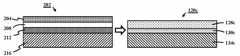
도 2는 본 기재의 예시적인 구현예에 따른 박형 유리 시트를 포함하는 다층 구조체의 개략적인 다이어그램이다.
도 3a는 본 기재의 예시적인 구현예에 따른 기계적 펑크 시험의 개략적인 다이어그램이다. 도 3b는 본 기재의 구현예에 따른 펑크 시험에서 박형 유리 시트를 포함하는 다층 구조체의 개략적인 다이어그램이다.
도 4a는 본 기재의 예시적인 구현예에 따른 박형 유리 시트의 기계적인 펑크 시험에 대한 이동 깊이(마이크로미터로, 이후 또한 "마이크로미터", "미크론즈" "미크론", 및 "㎛"로서 언급됨) 대 하중(N)의 데이터 곡선의 실시예를 나타낸다. 도 4b 및 4c는 실시예 기계적 펑크 시험 후 박형 유리 시트 시료의 2배율에서 균열 확대도를 나타낸다.
도 5a는 본 기재의 예시적인 구현예에 따른 서브-미크론 흠결을 제거하기 위하여 공정 전 및 후 기계적 펑크 시험 데이터의 그래픽 결과를 나타낸 것이다. 도 5b는 예시적인 구현예에 따른 기계적인 펑크 시험에서 사용되는 쿠션 층 상에서 박형 유리 커버의 개략적인 측면도를 나타낸 것이다.
도 6은 본 기재의 예시적인 구현예에 따른 다층에서 박형 유리 커버에 의해 대체될 수 있는 종래의 코팅 스택의 개략적인 측면도이다.
도 7a는 본 기재의 예시적인 구현예에 따른 대칭적 화학 강화된 초-박 유리 커버 유리의 개략적인 측면도이다. 도 7b는 본 기재의 예시적인 구현예에 따른 비대칭의 화학적 강화 초-박형 유리 커버 유리의 개략적인 측면도이다.
도 8a, 8b, 및 8c는 예시적인 구현예에 따른 기판 층에 동일한 초-박형 커버 유리 및 라미네이트를 강화하기 위한 예시적인 공정을 개략적으로 나타내는 측면도이다.
도 9a는 예시적인 구현예에 따른 박형 유리 시트를 포함하는 장치의 개략적인 측면도이다. 도 9b는 또 다른 예시적인 구현예에 따른 박형 유리 시트를 포함하는 장치의 개략적인 측면도이다.
도 10은 광 에칭 공정 없이 오버레이 유리에 본 기재의 예시적인 구현예에 따른 템퍼링 및 광 에칭 공정이 수행된 오버레이 유리 대비 오버레이 유리의 고장 에너지의 그래프이다.
도 11은 본 기재의 예시적인 구현예에 따른 19.02 mm 직경을 갖는 28 g 구의 구 낙하 시험에 대한 고장 에너지의 확률 그래프이다.
도 12는 본 기재의 예시적인 구현예에 따른 19.02 mm 직경을 갖는 28 g 구의 구 낙하 시험에 대한 평균에 대해서 95% 신뢰도 구간에서 mJ로 보호 유리 오버레이 충격 에너지의 그래프이다.
도 13은 보호 유리 시스템을 포함하는 모바일 장치의 개략적인 전면도이며, 여기서, 상기 보호 유리 시스템의 유리 오버레이는 본 기재의 예시적인 구현예에 따라 제1 및 제2의 주표면 상에서 강화된다.
도 14a, 14b, 및 14c는 본 기재의 예시적인 구현예에 따른 파괴 저항 시험을 나타내는 개략적인 다이어그램이다.
도 15a 및 15b는 본 기재의 예시적인 구현예에 따른 모사 모바일 전자 장치에 마운트된 보호 유리 오버레이의 필드 스크래치 이벤트(field scratch event)를 가속하고 모사하기 위한 텀블 시험을 개략적으로 나타낸다.BRIEF DESCRIPTION OF THE DRAWINGS The drawings, which are included to provide a better understanding of the present disclosure, form a part of the present disclosure and are included herein, illustrate exemplary embodiments of the present disclosure in conjunction with the description given to illustrate the principles of the disclosure.
1 is a schematic diagram of a multilayer structure including a polymer layer conventional sensor cover.
2 is a schematic diagram of a multilayer structure including a thin glass sheet according to an exemplary embodiment of the present disclosure.
3A is a schematic diagram of a mechanical puncture test in accordance with an exemplary embodiment of the present disclosure. 3B is a schematic diagram of a multilayer structure including a thin glass sheet in a puncture test according to an embodiment of the present disclosure.
4A shows the depth of movement (in micrometers, also referred to as “micrometers”, “microns”, “microns”, and “μm”) for mechanical puncture testing of thin glass sheets according to exemplary embodiments of the present disclosure. An example of a data curve of large load N is shown. 4B and 4C show crack enlargements at double magnification of thin glass sheet samples after Example mechanical puncture testing.
5A shows graphical results of mechanical puncture test data before and after processing to remove sub-micron defects in accordance with an exemplary embodiment of the present disclosure. 5B shows a schematic side view of a thin glass cover on a cushion layer used in a mechanical puncture test in accordance with an exemplary embodiment.
6 is a schematic side view of a conventional coating stack that may be replaced by a thin glass cover in multiple layers according to an exemplary embodiment of the present disclosure.
7A is a schematic side view of a symmetrical chemically strengthened ultra-thin glass cover glass in accordance with an exemplary embodiment of the present disclosure. 7B is a schematic side view of an asymmetric, chemically strengthened ultra-thin glass cover glass according to an exemplary embodiment of the present disclosure.
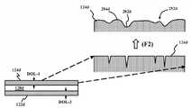
8A, 8B, and 8C are side views schematically illustrating an exemplary process for strengthening the same ultra-thin cover glass and laminate to a substrate layer according to an exemplary embodiment.
9A is a schematic side view of an apparatus including a thin glass sheet according to an exemplary embodiment.9B is a schematic side view of an apparatus including a thin glass sheet according to another exemplary embodiment.
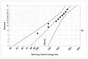
10 is a graph of failure energy of overlay glass versus overlay glass in which the tempering and light etching process was performed on the overlay glass without the light etching process in accordance with an exemplary embodiment of the present disclosure.
FIG. 11 is a probability graph of failure energy for a sphere drop test of a 28 g sphere with a 19.02 mm diameter in accordance with an exemplary embodimentof the present disclosure.
12 is a graph of protective glass overlay impact energy in mJ at 95% confidence interval for the mean for a sphere drop test of a 28 g sphere with a 19.02 mm diameter in accordance with an exemplary embodimentof the present disclosure.
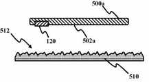
FIG. 13 is a schematic front view of a mobile device including a protective glass system, wherein the glass overlay of the protective glass system is reinforced on the first and second major surfaces in accordance with an exemplary embodiment of the present disclosure.
14A, 14B, and 14C are schematic diagrams illustrating fracture resistance tests in accordance with exemplary embodimentsof the presentdisclosure .
15A and 15B schematically illustrate a tumble test for accelerating and simulating field scratch events of a protective glass overlay mounted on a simulated mobile electronic device in accordance with an exemplary embodimentof the present disclosure.
본 기재는 본 기재의 구현예가 도시된 첨부된 도면을 참조하여 이후 좀 더 상세하게 기술된다. 그러나, 본 기재는 많은 다른 형태로 구현화될 수 있고, 본원에 설명된 구현예에 한정적으로 구속되어서는 안된다. 오히려, 이들 구현예는 본 기재가 당업자에게 본 기재의 범위를 충분히 그리고 완전하게 전달하도록 제공된다. 본 도면에서, 층들 및 영역의 크기 및 상대적인 크기는 명확성을 위하여 과장될 수 있다. 도면에서 유사 부호는 유사 부재를 나타낸다.This description is described in more detail below with reference to the accompanying drawings, in which embodiments of the invention are shown. However, the present disclosure may be embodied in many different forms and should not be limited to the embodiments described herein. Rather, these embodiments are provided so that this disclosure will fully and completely convey the scope of the disclosure to those skilled in the art. In this figure, the size and relative size of layers and regions may be exaggerated for clarity. Like numbers in the drawings indicate like elements.
부재 또는 층이 또 다른 부재 또는 층의 "상"에 또는 이에 "연결되는" 것으로 기술되는 경우, 이는 다른 부재 또는 층 상에 직접 또는 이들과 직접 연결될 수 있거나, 또는 중간 부재 또는 층이 존재할 수 있는 것으로 이해될 것이다. 반면, 부재 또는 층이 또 다른 부재 또는 층 "상에 직접" 또는 이에 "직접 연결되는" 것으로 기술되는 경우, 어떠한 중간 부재 또는 층도 존재하지 않는다. 본 기재에서 "적어도 하나의 X, Y, 및 Z"는 X 단독, Y 단독, Z 단독, 또는 둘 이상의 X, Y, 및 Z의 모든 조합(예를 들어, XYZ, XYY, YZ, ZZ)로 구성될 수 있는 것으로 이해될 것이다.When a member or layer is described as "connected" to or "connected" to another member or layer, it may be directly or directly connected to another member or layer, or an intermediate member or layer may be present. Will be understood. On the other hand, if a member or layer is described as "directly" or "directly connected" to another member or layer, then no intermediate member or layer is present. “At least one X, Y, and Z” herein refers to X alone, Y alone, Z alone, or any combination of two or more X, Y, and Z (eg, XYZ, XYY, YZ, ZZ). It will be understood that it can be configured.
본 기재의 예시적인 구현예는 다층 구조체 및 그 제조방법에 관한 것이다. 구체적으로, 본 기재의 예시적인 구현예는 다층 구조체의 고 강도, 초-박형 유리 시트, 유리 물질의 유리 오버레이를 포함하는 보호 유리 시스템 및 고 강도, 초-박 유리 시트를 갖는 다층 구조체의 제조방법에 관한 것이다.Exemplary embodiments of the present disclosure relate to multilayer structures and methods of making the same. Specifically, exemplary embodiments of the present disclosure provide a method of making a multilayer structure having a high strength, ultra-thin glass sheet of a multilayer structure, a protective glass system comprising a glass overlay of glass material and a high strength, ultra-thin glass sheet. It is about.
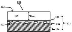
도 2에 도시된 바와 같이, 다층 구조체(120)는 유리 시트(128), 라미네이션 층(130), 및 기판 층(134)을 포함하며, 상기 유리 시트(128) 및 기판 층(134)은 라미네이션 층(130)을 통해서 함께 라미네이트되는 것으로, 예시적인 구현예에 따라 제공될 수 있다. 상기 라미네이션 층(130)은 광학적으로 투명할 수 있다. 상기 라미네이션 층(130)은 9 GPa 미만, 예를 들어, 7 GPa 미만, 5 GPa 미만, 또는 3 GPa 미만의 탄성 계수를 포함할 수 있다. 상기 라미네이션 층(130)은 약 20 ㎛ 미만의 두께, 예를 들어, 10 ㎛ 미만 두께, 5 ㎛ 미만 두께, 1 ㎛ 미만 두께일 수 있다. 예를 들어, 상기 라미네이트 층(130)은 흡착에 의해 적용되고 모노층의 분자일 수 있다.As shown in FIG. 2, the
상기 기판 층(134)은 25 GPa 초과의 탄성 계수를 가질 수 있다. 예를 들어, 상기 기판 층(134)은 40 GPa 초과의 탄성 계수, 예를 들어, 50 GPa 초과, 60 GPa 초과, 70 GPa 초과, 또는 80 GPa 초과의 탄성 계수를 가질 수 있다. 구현예에서, 상기 기판 층(134)은 라미네이트 층(130)의 탄성 계수의 5배를 초과하는 탄성 계수를 가질 수 있다. 상기 기판 층(134)은 유리 층을 포함할 수 있다. 나아가, 전기 전도성 경로를 포함하는 전자 부품층(138)은 상기 유리 시트 및 기판 층(134) 사이에, 예를 들어, 기판 층(134) 상에 배치될 수 있다.The
상기 유리 시트(128)는 예를 들어, 250 ㎛ 미만 두께, 예를 들어, 200 ㎛ 미만 두께, 150 ㎛ 미만 두께, 100 ㎛ 미만 두께, 70 ㎛ 미만 두께, 또는 50 ㎛ 미만 두께의 초-박형일 수 있다. 상기 유리 시트(128)는 제1의 템퍼 표면(122) 및 제2의 템퍼 표면(124)을 포함할 수 있다. 적어도 상기 제1의 템퍼 표면(122)은 후술되는 바와 같이 적어도 5 마이크로미터의 깊이를 갖는 표면 압축층 및 적어도 200 MPa의 표면 압축 응력을 포함한다. 예를 들어, 상기 표면 압축 응력은 적어도 200 MPa, 및 800 MPa 이하일 수 있고, 층의 깊이(DOL)는 약 5 미크론 및 약 30 미크론 사이의 범위일 수 있으며, 예를 들어, 상기 DOL은 약 10 미크론 및 약 30 미크론 사이의 범위, 또는 약 10 미크론 및 약 20 미크론 사이의 범위일 수 있다. 상기 유리 시트(128)는 커버 유리, 유리 오버레이 및 그 유사물과 같은 초-박형 유리일 수 있다. 상기 유리 시트가 예를 들어, 70 ㎛ 두께 미만 또는 50 ㎛ 두께 미만의 초-박형인 경우, 30 ㎛의 DOL이 달성하기 어려울 수 있으며, 이러한 초-박형 유리의 경우, 상기 DOL은 대신 초-박형 유리 시트 두께의 20% 까지일 수 있다.The
상기 다층 구조체(120)에서 유리 시트(128)의 펑크 계수, Pf는 B10 (고장 확률 분포의 10번째 백분위수)에서 적어도 3000 N/mm2일 수 있다. 상기 펑크 계수는 상기 유리 시트(128)의 제곱된 두께 t에 대한 고장에서의 펑크 하중의 비, Pf = P/t2이다. 여기서, 상기 펑크 계수는 분 당 200 뉴턴인 초 당 약 30 뉴턴의 속도에서 선형으로 증가하는 하중 하에, 상기 유리 시트(128)의 적어도 하나의 템퍼 표면에 걸쳐 중심에 있는 1.5 mm 직경 구형 세그먼트 팁에 의해 측정된다. 상기 라미네이트 층(130)이 10 ㎛ 미만의 두께인 경우, 상기 펑크 계수는 B10에서 3000 N/mm2를 훨씬 초과할 수 있다.The puncture coefficient, Pf, of the
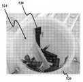
도 3a는 예시적인 구현예에 따른 기계적 펑크 시험 장치(300)의 개략적인 다이어그램이다. 라미네이트 층(130a)과 같은 저-모듈러스 구조체 및 기판층(134a)과 같은 기판 층 위에 위치된 초-박형 유리(128a)의 거동은 구 낙하 시험, 가속화된 표면 손상 시험, 낙하 시험 및 펑크 시험에 의해 특성화될 수 있다. 상기 구 낙하 시험은 초-박형 유리 오버레이(128a)의 표면 강도를 시험할 수 있다. 상기 가속화된 표면 손상 시험은 약 45분에서 축적 인-서비스 손상의 연(year)에 대해 대략적으로 동등한 초-박형 유리 오버레이(128a)의 표면 스크레치 이벤트를 모사할 수 있다. 상기 낙하 시험은 화강암 및 아스팔트와 같은 다양한 표면 상에서 낙하 이벤트에 대해 초-박형 유리 오버레이(128a)의 날카로운 접촉 손상을 모사할 수 있다. 상기 펑크 시험은 초-박형 유리 오버레이(128a)의 표면 강도를 또한 시험할 수 있으며, 구 낙하 시험 대비 물질 성질을 연구하기 위하여 좀 더 제어된 시험으로 고려될 수 있다. 도 3에서, 공초점의 펜(304)은 구형 세그먼트 팁(308)을 포함하는 인덴터가 힘(316)에 의해 지지체(314) 상에서 다층 시료(120a) 내로 가압되는 경우 정밀한 변위 측정을 수행할 수 있다. 상기 하중은 하중 셀(320)에 의해 측정될 수 있다. 상기 인덴터 구형 세그먼트 팁(308)은 약 1.5 mm의 직경을 갖는 구를 포함할 수 있다. 충분히 빠른 하중재하속도가 로딩 현상 시 피로를 방지하기 위하여 선택될 수 있다. 상기 하중재하속도는 1분 시간 간격에 대해 최대 로딩 속도 값을 적용하고 시험하기 위한 충분히 최대 부호 속도를 갖는 적합한 하중 셀(320)에 기초하여 선택될 수 있다.3A is a schematic diagram of a mechanical
상기 펑크 시험은 예를 들어 분 당 최대 하중 셀 속도에 대응하는 속도에서 로딩하고 언로딩하는, 구형 세그먼트 팁(308) 하에서 고장(324) 및 언로딩에 대해 거리 "d"를 대체하도록 초-박형 유리 오버레이 시료(128a)를 로딩하는 단계를 포함할 수 있다. 유리(128a)가 균열(324)되는 깊이 "d"는 공초점의 펜(304)에 의해 결정될 수 있는 깊이에서의 급상승에 대응한다. 상기 균열 현상(324)에서의 하중은 펑크 하중이다.The puncture test is ultra-thin to replace the distance “d” for
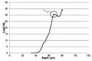
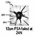
도 4a는 다층 시료(120b)에서 초-박형 유리 시트(128a)의 기계적 펑크 시험에 대한 변위 깊이(㎛)에 대한 하중(N)의 실시예를 나타낸다. 도 4a에서 샘플은 200 N/min (30 N/s)의 하중재하속도 및 1000 mN의 접촉 하중을 갖는 200 N/min의 언로딩재하속도에서 200 N로 로딩되었다. 급상승 깊이에서의 하중 및 깊이 "d"는 상기 그래프에서 명확하게 관찰될 수 있다. 도 4b 및 4c는 실시예 기계적 펑크 시험 후 박형 유리 시트 시료(128a)의 2배율에서의 균열(324) 확대도를 나타낸다. 인덴터 세그먼트 팁(308) 형상에 대응하는 원뿔형 인덴테이션(408) 및 균열(404)을 상기 확대도에 나타낸다.4A shows an embodiment of the load N versus depth of displacement (μm) for the mechanical puncture test of the
상기 다층 구조체(120, 120a)에서 유리 시트(128, 128a)의 제2의 템퍼 표면(124)은 적어도 10 마이크로미터의 깊이를 갖는 표면 압축층 및 적어도 200 MPa의 표면 압축 응력을 포함할 수 있으며, 상기 제2의 템퍼 표면 압축 층 깊이는 상기 제1의 템퍼 표면(122) 압축 층 깊이 미만일 수 있다.The
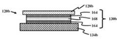
상기 라미네이트 층(130, 130a)과 같은, 낮은 모듈러스 다층 구조체 상에 배치된 0.2 mm 미만의 두께의 유리 물질의 박형 유리 시트(128, 128a)는 기술된 바와 같은 펑크 이벤트 시 높은 하중을 지탱할 수 있다.유리 물질이 좀 더 높은 펑크 하중을 지탱할 수 있도록 박형 유리 시트(128, 128a)의 제1의 표면(122) 상에 서브미크론 흠결을 제거함으로써 표준 물질에 비해 개선이 달성될 수 있다. 예를 들어, 서브-미크론 제거 공정이 수행되지 않은, 비-처리된 샘플에 비해서 강도에서 50/5 초과의 증가가 발견되었다. 도 5a는 본 기재의 예시적인 구현예에 따른 서브-미크론 흠결을 제거하기 위한 공정 전 및 후 기계적 펑크 시험 데이터의 그래프 결과를 나타낸다. 도 5b는 예시적인 구현예에 따른 기계적 펑크 시험에서 사용된 쿠션 층(130b) 상에 박형 유리 커버(128b)를 갖는 다층(120b)의 개략적인 측면도이다. 상기 박형 유리 층(128b)은 70 ㎛ 두께였고, 블랭크 유리 기판(134b) 상에 PAS(164)의 또 다른 6 ㎛ 두께 층 상에 Kapton® HN 폴리이미드 필름(168)의 125 ㎛ 두께 층 상에 압력-민감성 접착제(PSA) 폴리머 층(164)의 6 ㎛ 두께 층 상에 배치되었다. 상기 그래프에서 솔리드의 원은 박형 유리 층(128, 128a, 128b)의 비-처리된 대조 시료의 고장에 대해 로딩된 %를 나타낸다. 사각형은 제거된 박형 유리 시트(128, 128a, 128b)의 표면 상에 서비미크론 흠결을 갖는 예시적인 시료의 고장에 대해 로딩된 %를 나타낸다. 도 5a에서의 데이터는 서브-미크론 흠결을 제거하기 위한 공정 전 후 펑크 성능에서의 향상을 나타낸다.
상기 제1의 표면(122) 상의 서브미크론 흠결을 제거하기 위하여 기술된 바와 같은 상기 박형 유리 시트(128, 128a, 128b)의 제2의 표면(124) 상의 서브미크론 흠결을 제거함으로써, 상기 박형 유리 시트(128, 128a, 128b)는 인-서비스 사용 시 접촉으로부터의 스크래치 및 마모와 같은 표면 손상을 지탱할 수 있다.The thin glass by removing submicron defects on the
오버레이를 포함하는 센서의 신호-대-잡음 비 (SNR)는 상기 오버레이 물질의 겉보기 두께, tapp에 의해 직접 결정될 수 있다. 상기 겉보기 두께는 상기 오버레이 물질의 유전 상수, k에 의해 나눠진 오버레이 물질의 실제 두께 t에 의해 정의될 수 있다:The signal-to-noise ratio (SNR) of the sensor including the overlay can be directly determined by the apparent thickness of the overlay material, tapp . The apparent thickness may be defined by the actual thickness t of the overlay material divided by the dielectric constant of the overlay material, k:
tapp = t/ktapp = t / k
상기 센서 SNR 또는 이미지 품질은 유전 상수를 증가시키거나 또는 오버레이 물질의 실제 두께를 감소시키는 것 중 하나에 의해 향상될 수 있다. 상기 오버레이의 두께는 충분한 기계적 내구성에 요구되는 물질의 최소 두께에 의해 결정될 수 있다. 초-박형 커버는 커버 유리 물질 시스템과 같은 종래의 오버레이 시스템에 비해 높은 SNR을 위한 기회를 제공하는 실제 두께 거리를 감소시킬 수 있다.The sensor SNR or image quality can be improved by either increasing the dielectric constant or reducing the actual thickness of the overlay material. The thickness of the overlay can be determined by the minimum thickness of the material required for sufficient mechanical durability. Ultra-thin covers can reduce the actual thickness distance that provides an opportunity for higher SNR compared to conventional overlay systems such as cover glass material systems.
본 구현예에 따른 박형 유리 오버레이는 또한 이러한 장치가 높은 전압으로 구동될 필요가 없으며, 이는 예를 들어, 장치 배터리 수명을 향상시키고 좀 더 빠른 이미지 검출 반응 시간을 제공할 수 있으므로 센서 장치를 위한 좀 더 낮은 파워 소비를 제공한다. 서브미크론 흠결을 제거하기 위한 처리 공정은 모바일 장치를 포함하는 많은 적용에서 사용되기 위한 박형 커버를 제공하기 위한 내구성을 개선하며, 여기서 하부 센서 스택은 준수 또는 필로우 효과로 기술되는 낮은 유효 모듈러스를 갖는다.The thin glass overlay according to this embodiment also eliminates the need for such devices to be driven at high voltages, which can, for example, improve device battery life and provide faster image detection response times. Provide lower power consumption. The treatment process for removing submicron defects improves the durability to provide a thin cover for use in many applications, including mobile devices, where the lower sensor stack has a low effective modulus described by the compliance or pillow effect.
상기 초-박형 커버 솔루션은 종래의 유리, 폴리머 솔루션보다 좀 더 박형일 수 있으며, 폴리머 계 센서보다 좀 더 내구성을 가질 수 있으며, 사파이어 또는 지르코니아와 같은 결정 물질에 비해 비용적인 이점을 가질 수 있다.The ultra-thin cover solution may be thinner than conventional glass, polymer solutions, may be more durable than polymer based sensors, and may have a cost advantage over crystalline materials such as sapphire or zirconia.
따라서, 구현예의 유리 시트(128, 128a, 128b)는 0.014 mm 미만의 겉보기 두께 tapp를 포함할 수 있으며, 여기서 상기 겉보기 두께는 유리 시트 유전 상수 k에 의해 나눠진 유리 시트 두께 t, tapp = t/k이다. 상기 다층 구조체(120, 120a, 120b)에서 유리 시트(128, 128a, 128b)는 또한 6H 초과의 연필 경도를 포함할 수 있으며, 여기서 연필 경도는 후술되는 바와 같이 템퍼링 및 광 에칭에 따른 ASTM D 3363 및 ISO 15184 검사 표준으로 측정된다.Thus, the
상기 유리 시트(128, 128a, 128b)는 열 템퍼되거나 및/또는 화학 템퍼될 수 있다. 비대칭의 또는 대칭의 화학 강화된 초-박형 박형 유리 시트(128, 128a, 128b)는 카메라, 터치 스크린 및 그 유사물 위에 사용될 수 있으므로, 광 센서, 압력 센서, 거리 센세와 같은 센서용 보호 또는 오버레이 층을 제공할 수 있다. 좀 더 박형의 커버 유리가 바람직하므로, 비대칭의 화학 강화 또는 이온 교환(IOX) 강화가 상기 제1의 또는 제2의 템퍼 표면(122, 124) 방향으로 중심 장력을 이동시킴으로써 대칭성 IOX로 달성되는 것보다 좀 더 깊은 IOX 깊이, 또는 층의 깊이(DOL)를 제공할 수 있다. 예를 들어, 상기 DOL이 상기 제1의 템퍼 표면(122) 상에서 더욱 깊은 경우, 상기 중심 인장은 상기 제2의 템퍼 표면(124) 방향으로 이동될 수 있다. 비대칭성 IOX (AIX)는 좀 더 깊은 DOL을 갖는 이온-교환된 면 상에서 달성된 DOL에 대해 취약성을 감소시킬 수 있다. 상기 유리 두께가 50 ㎛ 미만이므로, 좀 더 깊은 DOL이 AIX로 박형 유리에서 생성될 수 있으며, 따라서 표준 IOX에 의해 달성될 수 있는 것보다 더욱 높은 압축 응력이 AIX로 달성될 수 있다.The
또한, 산화 알루미늄, 질화 알루미늄, 산질화 알루미늄 및 그 유사물과 같은 내-스크래치성 코팅은 좀 더 얕은 DOL을 갖는 이온 교환된 표면인 AIX 커버 유리(120, 120a, 120b)의 제2의 템퍼 표면(124)의 상부 표면 상에 코팅될 수 있다. 유사하게, 반사방지 코팅이 또한 AIX 커버 유리(120, 120a, 120b)의 제2의 템퍼 표면(124) 상에 코팅될 수 있다. 나아가, 색상 필터 필름 스택이 원하는 색상에 대해 상기 유리 표면 상에 코팅될 수 있다.In addition, the scratch-resistant coatings, such as aluminum oxide, aluminum nitride, aluminum oxynitride and the like, have a second temper surface of the
도 6은 본 기재의 예시적인 구현예에 따라 박형 유리 다층(120c)에 의해 대체될 수 있는 종래의 코팅 스택(202)의 개략적인 측면도이다. 상기 종래의 코팅 스택(202)은 유리 기판 층(216) 상에 정전기 방전(ESD) 보호 층(212) 상에 색상 층(208) 상에 하드 코팅(204)을 갖는다. 커버 스택으로서 또한 언급될 수 있는 박형 유리 다층(120c)은 유리 기판 층(134c) 상에 접착제 층(130c) 상에 박형 유리 시트 층(128c)을 갖는다. 상기 구현예는 종래의 유기 및/또는 무기 코팅 스택(202)을 대체하기 위하여 보호층과 같이 50 ㎛ 미만의 두께를 갖는 비대칭 및/또는 대칭 화학 강화된 초-박형 유리(128c)를 사용할 수 있다.6 is a schematic side view of a
도 7a는 본 기재의 예시적인 구현예에 따른 대칭의 화학 강화 초-박형 유리 커버 유리(128d)의 개략적인 측면도이다. 도 7b는 본 기재의 예시적인 구현예에 따른 비대칭의 화학적 강화 초-박형 유리 커버 유리(128e)의 개략적인 측면도이다. 상기 대칭의 화학적 강화 초-박형 유리 커버 유리(128d)는 이온 교환이 다다르지 않는 중심 영역(244)에 대해 각각 압축 층(DOL)을 갖는 제1의 이온 교환된 표면(122d) 및 제2의 이온 교환된 표면(124d)를 가질 수 있다. 따라서, 상기 중심 영역(244)은 중심 장력(260)을 가질 수 있다. 상기 비대칭의 화학 강화된 초-박형 유리 커버 유리(128e)는 상기 비-이온-교환된 영역(244e)이 반대 표면 방향으로 이동되고 상기 AIX 초-박형 유리 커버 유리(128e) 내의 중심 장력(260e)이 동일 방향으로 이동되도록 제1의 표면(122e) 상에 압축층(DOL)을 갖는다. 도 7a 및 7b는 상기 제2의 표면(124d) 방향으로 중심 장력(260, 260e)을 이동시킴으로써 표준 IOX로 달성되는 좀 더 깊은 DOL을 제공할 수 있으며, 상기 제1의 표면(122d, 122 e) 상에서 달성된 DOL에 대해 취약성을 감소시킴을 나타낸다.7A is a schematic side view of a symmetrical chemically strengthened ultra-thin
도 8a 및 8b를 참조하면, 비대칭의 화학 강화 공정이 기술될 수 있다. 도 8a는 본 예시적인구현예에 따른 기판 층(134f)에 커버 유리(128f)를 라미네이트하고 초-박형 커버 유리(128f)를 강화시키기 위한 공정의 개략적인 측면도를나타낸다. 예를 들어, 작동 (A)에서, 50 ㎛ 두께의 초-박형 커버 유리(128f)가 제공될 수 있으며, 작동 (B)에서 보호층으로서 알루미늄(264)의 박형 층(약 50 nm 두께)이 상기 유리(128f)의 일면 상에서 열적으로 증착될 수 있다. 예를 들어, 상기 제2의 표면(124f) 상에서. 작동 (C)에서, 상기 알루미늄(264) 보호된 유리(128f)는 유리(128f)를 살짝 벤드하기 위하여 클램핑 고정물에 위치될 수 있다. 이는 비대칭의 이온 교환 공정을 위한 초기 압축력을 제공하기 위하여 수행될 수 있다. 상기 유리에의 클램프는 용융 질화 칼륨 욕 내에 위치되기 전에 410℃로 예비가열될 수 있다. 상기 샘플은 약 1.25 시간 동안 상기 욕 내에 남겨질 수 있다. 여전히 뜨거운 한편 실온으로 냉각시킬 수 있도록 제거될 수 있다. 상기 염은 탈염수(DI)로 헹굴 수 있고, 상기 알루미늄(264)은 작동 (D)에서 알루미늄 부식액으로 제거될 수 있다. 이온 교환 면(124f)을 갖는 유리 층(128f)은 DI 수 및 에탄올로 헹굴 수 있다. 상기 제2의 표면(124f)의 표면 응력 미터 측정이 취해질 수 있으며, 약 200 MPa의 압축 응력 및 약 10 ㎛의 DOL을 나타낼 수 있다. 이러한 측정에서, 일본의 ORIHARA INDUSTRIAL CO., LTD에 의해 제조된 FSM-6000LETM 표면 응력 미터가 사용될 수 있다. 상기 작동 (B), (C), 및 (D)는 상기 초-박형 커버 유리(128f), 예를 들어 제1의 표면(122f)의 다른 면을 이온 교환하기 위하여 반복될 수 있다. 상기 제1의 표면(122f)의 표면 응력 미터 측정이 취해지고 약 20 ㎛의 DOL 및 약 770 MPa의 압축 응력을 나타낼 수 있다. 상기 AIX 유리(128f)는 라미네이션 층(130f)으로 센서 기판과 같은 전자 장치 기판(134f)에 라미네이트될 수 있다. 상기 라미네이션 공정은 작동 (E)에서 공정되어 다층 구조체(120f)를 초래한다. 실시예에서, 지문 센서 적용에서 비대칭적으로 이온 교환된 유리의 내구성을 검사하기 위하여, 상기 유리(128f)가 라미네이션 층(130f)으로서 UV 경화성 접착제를 사용하여 센서 기판(134f)에 라미네이트되었다. 상기 접착제는 에폭시/옥세테인(oxetane) 블렌드이며, 약 5 GPa의 탄성 계수를 갖는다. 상기 라미네이션 층(130f)의 두께는 10 ㎛의 차수 상에 있다.8A and 8B , an asymmetric chemical strengthening process can be described. Figure8a is acover glass laminate and a second (128f) on a substrate layer (134f) accordingtothe present exemplaryembodiment- isshowna schematic side view of the process for strengthening the thin cover glass (128f). For example, in operation (A), a 50 μm thick
도 8a에 나타낸 구현예에서, 상기 AIX 유리(128f)는 작동 (E)에서 기판(134f)에 대해 유리층(128f)을 라미네이트 하기 전에 표면에서의 작은 결점을 제거하기 위하여 산 에칭(광 에칭으로 언급됨)에 의해 더욱 강화될 수 있다. 도 8b및8c는 예시적인구현예에 따른 초-박형 커버 유리(128d, 128e, 128f)를 강화하기위한 예시적인 공정의 개략적인 측면도이다. 작동 (F1), (F2)에서, 상기 이온 교환된 제1의 표면(122d, 122e, 122f) 또는 제1 및 제2의 표면(122d, 122e, 122f 및 124d, 124e, 124f)은 결점을 제거하고 예리한 피쳐를 평탄화함으로써 초-박형 유리 층(128d, 128e, 128f)에 추가적인 강도를 제공하기 위하여 압축 층(DOL)의 깊이 미만으로 광 에칭될 수 있다. 예를 들어, 상기 광 에칭은 불소 화합물을 함유하는 산 용액으로 수행될 수 있다. 예를 들어, 2 ㎛ 초과 두께의 표면 유리가 광 에칭에 의해 제거될 수 있다.In the embodiment shown in FIG. 8A, the
도 8b에 나타낸 바와 같이, 상기 제1의 템퍼 표면(122e)의 DOL-1은 상기 제2의 템퍼 표면(124e)의 DOL-2를 초과할 수 있다. 한편, 도 8c에 나타낸 바와 같이, 제1의 템퍼 표면(122d)의 DOL-3는 상기 제2의 템퍼 표면(124d)의 DOL-4와 실질적으로 동일할 수 있다.As shown in FIG. 8B, the DOL-1 of the
또 다른 예시적인 구현예는 다층 구조체(120, 120a-c, 120f)의 제조방법을 개시한다. 상기 방법은 유리 시트(128)의 적어도 하나의 주표면(122, 122d-f, 124, 124d-f)을 이온-교환 템퍼링(B)하는 단계, 적어도 하나의 주표면(122, 122d-f, 124, 124d-f)을 광 에칭(F1), (F2)하여 표면 흠결을 제거하는 단계, 상기 템퍼되고 광 에칭된 적어도 하나의 표면(122, 122d-f, 124, 124d-f) 상에 라미네이트 층(130, 130a-c, 130f)을 증착하는 단계, 및 상기 유리 시트(128, 128a-f) 및 기판 층(134, 134a-c, 134f)을 함께 라미네이트하기 위하여 라미네이트 층(130, 130a-c, 130f) 상에 기판 층(134, 134a-c, 134f)을 증착하는 단계를 포함한다. 상기 다층 구조체(120, 120a-c, 120f)에서 유리 시트(128, 128a-f)의 펑크 계수, Pf는 B10 (고장 확률 분포의 10번째 백분위수)에서 적어도 3000 N/mm2 이다. 상기 펑크 계수는 유리 시트(128, 128a-f)의 제곱된 두께 t에 대한 고장에서 펑크 하중의 비이며, 펑크 계수는 유리 시트(128, 128a-f)의 적어도 하나의 주표면(122, 122d-f, 124, 124d-f)에 걸쳐 중심이 있는 1.5 mm 직경 구형 세그먼트 팁(308) 및 초 당 약 30 뉴턴의 속도에서 선형으로 증가하는 하중에 의해 측정된다.Yet another exemplary embodiment discloses a method of making a
도 9a는 예시적인구현예에 따른 박형 유리 시트(128g)를 포함하는 다층 장치(120g)의 개략적인 측면도이다. 도 9a에 나타낸 바와 같이, 상기 유리 층(128g) 제2의 템퍼 표면(124g)은 상기 제1의 템퍼 표면(122g) DOL 초과의 DOL을 가질 수 있으며, 여기서 상기 제1의 템퍼 표면(122g)은 상기 라미네이션 층(130g) 상에 배치되며, 상기 라미네이션 층(130g)은 상기 기판 층(134g) 상에 배치된다. 도 9b는또 다른 예시적인 구현예에 따른 박형 유리 시트(128h)를 포함하는 다층 장치(120h)의 개략적인 측면도이다. 도 9b에서, 상기 유리 층(128h)은 강화되며 실질적으로 균등한 압축 DOL을 갖는 두 개의 주표면(122h 및 124h)을 가질 수 있다. 상기 제1의 템퍼 표면(122h)은 상기 라미네이션 층(130h) 상에 배치될 수 있으며, 상기 라미네이션 층(130h)은 기판 층(134h) 상에 배치될 수 있다.9A is a schematic side view ofa
일부 구현예에서, 상기 제1의 템퍼 표면(122g) DOL은 제2의 템퍼 표면(124g) DOL보다 더욱 박형일 수 있는 한편, 바람직하게는 상기 제1의 템퍼 표면(122g)은 제2의 템퍼 표면(124g) 보다 큰 표면 압축 응력을 동시에 가질 수 있다. 일부 구현예에서, 상기 제1의 템퍼 표면(122h) DOL은 상기 제2의 템퍼 표면(124h) DOL과 실질적으로 동일한 두께일 수 있는 한편, 상기 제1의 템퍼 표면(122h)은 상기 제2의 템퍼 표면(124h)보다 더욱 큰 표면 압축 응력을 동시에 가질 수 있다. 일부 구현예에서, 상기 제1의 템퍼 표면(122e, 122f) DOL은 상기 제2의 템퍼 표면(124e, 124f) DOL보다 더욱 두꺼울 수 있는 한편, 상기 제1의 템퍼 표면(122e, 122f)은 상기 제2의 템퍼 표면(124e, 124f) 보다 더욱 큰 표면 압축 응력을 동시에 가질 수 있다. 일부 구현예에서, 상기 제2의 템퍼 표면(124, 124d-124h)은 상기 제1의 템퍼 표면(122, 122d-122h)보다 더욱 큰 표면 압축 응력을 가질 수 있다. 바람직하게는, 상기 제1의 템퍼 표면(122, 122d-122h)은 상기 제2의 템퍼 표면(124, 124d-124h)보다 더욱 큰 표면 압축 응력을 갖는다. 일부 구현예에서, 상기 제2의 템퍼 표면(124, 124d-124h)은 상기 제1의 템퍼 표면(122, 122d-122h)과 실질적으로 동일한 표면 압축 응력을 가질 수 있다. 상기 구현예에서, 제1의 및 제2의 템퍼 표면( 122g, 122h, 124g, 124h) 모두는 상기 표면 압축층의 깊이 미만으로 템퍼되고 화학적으로 에칭(광 에칭)될 수 있다.In some embodiments, the
도 9a 및 9b를 참조하면, 예를 들어, 상기 유리 시트(128g, 128h)는 0.014 mm 미만의 겉보기 두께, tapp를 가질 수 있다. 상기 겉보기 두께는 유리 시트 유전 상수, k로 나눈 유리 시트(128g, 128h) 두께, t, k: tapp = t/k를 나타낸다. 또한, 상기 다층 구조체(120g, 120h)는 6H 초과의 연필 경도를 가질 수 있으며, 여기서 연필 경도는 ASTM D 3363 및 ISO 15184 검사 표준에 의해 측정된다.9A and 9B, for example, the
도 2, 및7a 내지 9b를 참조하면, 또 다른 예시적인 구현예는 보호 유리 시스템(120, 120f-h)을 개시한다. 상기 보호 유리 시스템(120, 120f-h)은 유리 물질의 유리 오버레이(128, 128d-h) 및 층들의 스택(130, 130f-h, 134, 134f-h, 및 138, 138f-h)을 포함하는 언더레이(132, 132f-h)를 포함할 수 있다. 상기 유리 오버레이(128, 128d-h)는 서로 떨어진 제1의 주표면(122, 122d-h) 및 제2의 주표면(124, 124d-h), 및 제1의 및 제2의 주표면(122, 122d-h 및 124, 124d-h) 사이의 250 마이크로미터 미만의 두께 t를 포함할 수 있다. 상기 유리 오버레이(128, 128d-h)는 상기 제1의 주표면(122, 122d-h) 상에서 강화될 수 있으며, 상기 제1의 주표면(122, 122d-h)에서의 압축 응력은 적어도 200 MPa일 수 잇으며, 상기 압축 응력은 제1의 주표면(122, 122d-h)으로부터 적어도 5 마이크로미터일 수 있는 층의 깊이 DOL까지 안쪽으로 연장할 수 있다. 예를 들어, 상기 표면 압축 응력은 적어도 200 MPa, 800 MPa 이하일 수 있으며, 층의 깊이(DOL)는 약 5 미크론 및 약 30 미크론 사이의 범위일 수 있으며, 예를 들어, 상기 DOL은 약 10 미크론 및 약 30 미크론 사이의 범위, 또는 약 10 미크론 및 약 20 미크론 사이의 범위일 수 있다. 상기 유리 오버레이(128, 128d-h)는 커버 유리, 유리 시트 및 그 유사물과 같은 초-박형 유리일 수 있다. 상기 유리 오버레이(128, 128d-h)가 초-박형인 경우, 예를 들어, 70 ㎛ 두께 미만, 또는 50 ㎛ 두께 미만인 경우, 이러한 초-박형 유리의 경우에, 상기 DOL은 초-박형 유리 시트 두께의 20% 까지일 수 있으므로 30 ㎛의 DOL이 달성하기 어려울 수 있다.2, and7A-9B , another exemplary embodiment discloses
상기 언더레이(132, 132f-h)의 제1의 층(130, 130f-h)은 쿠션층일 수 있으며, 5 GPa 미만인 낮은 탄성 계수를 가질 수 있으며, 상기 언더레이의 제2의 층(134, 134f-h)은 상기 제1의 층(130, 130f-h)의 탄성 계수의 적어도 5배의 탄성 계수를 갖도록 딱딱할 수 있다. 상기 언더레이(132, 132f-h)의 제1의 층(130, 130f-h)은 상기 언더레이(132, 132f-h)의 제2의 층(134, 134f-h) 및 유리 오버레이(128, 128d-h) 사이일 수 있으며, 상기 제1의 층(130, 130f-h)은 상기 유리 오버레이(128, 128d-h) 및 200 마이크로미터 이하인 제2의 층(134, 134f-h) 사이의 두께를 가질 수 있으며, 따라서 상기 언더레이(132, 132f-h)의 제1의 층(130, 130f-h) 내로의 유리 오버레이(128, 128d-h)의 과도한 굴절이 상기 언더레이(132, 132f-h)의 제2의 층(134, 134f-h)에 의해 억제될 수 있다.The
상기구현예에서, 상기 유리 오버레이(128, 128d-h)의 제1의 주표면(122, 122d-h)은 광 에칭을 나타내는 표면 피쳐(252e)를 가질 수 있다(도 8b). 상기 제1의 주표면(122e)은 1000Х 광학 현미경 검사 시 스무드-롤링 핏(282e) 및 범프(284e)를 가질 수 있으며, 대부분의 핏(282e) 및 범프(284e)는 1 마이크로미터 미만일 수 있는 제1의 주표면(122e)의 인접 부분에 직각인 높이 또는 깊이를 갖는 크기로 서브미크론일 수 있다.In thisembodiment , the first
상기구현예에서, 상기 언더레이(132, 132f-h)의 제3의 층은 전기적으로 전도성 경로(138)를 포함하는 전자 부품을 포함할 수 있다. 상기 제3의 층은 유리 오버레이(128, 128d-h) 및 제1의 층(130, 130f-h) 사이에 위치될 수 있다. 상기 유리(128, 128d-h)는 20 마이크로미터 이하의 초-저 겉보기 두께 tapp 를 가질 수 있으며, 여기서 겉보기 두께 tapp 는 유리 물질의 유전 상수 k에 의해 나눈 두께 t이며, 따라서, 상기 전자 부품(138)의 유리 오버레이(128, 128d-h)를 통해서 전보 통신용 신호-대-잡음 성능을 유리하게 한다. 상기 보호 유리 시스템(120, 120f-h)은 B10 (고장 확률 분포의 10번째 백분위수)에서 적어도 3000 N/mm2의 펑크 계수, Pf를 가질 수 있으며, 여기서 펑크 계수는 상기 유리 오버레이(128, 128d-h)의 제2의 주표면(124, 124d-h)에 걸쳐 중심이 있는 1.5 mm 직경 구형 세그먼트 팁(308) 및 초당 약 30 뉴턴의 속도에서 선형으로 증가하는 하중에 의해 측정된다.In thisembodiment , the third layer of the
이러한 구현예 중 일부에서, 상기 유리 물질은 보로실리케이트 유리일 수 있다.In some of these embodiments, the glass material may be borosilicate glass.
상기구현예에서, 상기 유리 오버레이는 약 190 mJ의 평균 블런트 충격 접촉 에너지 및 120 mJ 초과의 확률 분포 블런트 충격 접촉 에너지의 10번째 백분위수(B10)를 가질 수 있으며, 여기서 상기 블런트 충격 접촉 에너지는 상기 보호 유리 시스템에서 유리 오버레이 상에 직접 28 그램, 19.02 mm 직경 구를 낙하하여 측정된다. 상기 200mJ의 평균 에너지는 센서 커버 적용을 위한 50 mJ (20 cm에서 25 g 구)의 "통상적인" 요구보다 훨씬 높다. 상기 블런트 충격 시험은 모사 센서 커버에서 통합된 다층 스택 구조체에서 보호 커버 유리 상에 28g 구를 낙하함으로써 수행되었다.In thisembodiment , the glass overlay may have an average blunt impact contact energy of about 190 mJ and a tenth percentile B10 of a probability distribution blunt impact contact energy of greater than 120 mJ, wherein the blunt impact contact energy is Measured by dropping a 28 gram, 19.02 mm diameter sphere directly onto the glass overlay in a protective glass system. The average energy of 200 mJ is much higher than the “typical” requirement of 50 mJ (25 g sphere at 20 cm) for sensor cover application. The blunt impact test was performed by dropping 28 g spheres on the protective cover glass in the multilayer stack structure integrated in the simulated sensor cover.
노출된 오버레이를 갖는 모사 센서는 낙하 이벤트 또는 블런트 대상과의 접촉에 기인하여 블런트 충격 손상을 입을 수 있다. 이들 이벤트의 생존율을 측정하기 위하여, 구 낙하 시험이 수행되었다. 구 낙하 시험을 수행하는데 고정물이 사용되었다. 인-서비스 사용에 기반하여, 상기 오버레이 유리는 50 mJ의 충격 에너지만큼 높게 생존할 필요가 있을 수 있다.Simulated sensors with exposed overlay can suffer blunt impact damage due to drop events or contact with the blunt object. In order to measure the survival rate of these events, a sphere drop test was performed. Fixtures were used to perform the ball drop test. Based on in-service use, the overlay glass may need to survive as high as 50 mJ impact energy.
상기 시험 샘플은 모사 센서 상에 어셈블리 되고 0.3 mm 충격 패드를 갖는 스테인리스-강 플레이트 상에 마운트되었다. 28g 구가 5 cm에서 개시하여 낙하되었고, 낙하 높이가 오버레이 유리가 균열될 때까지 연속적으로 5 cm 증가되었다. 10개의 샘플이 시험되었다. 모든 샘플은 50 mJ 초과의 에너지에서 잘 생존하였다. 상기 고장 에너지는 96mJ 내지 265 mJ 범위였다. 상기 10번째 백분위수 고장 에너지는 또한 50 mJ (B10: 128 mJ)에서 일반적인 요구를 초과하였다.The test sample was assembled on a simulated sensor and mounted on a stainless steel plate with a 0.3 mm shock pad. The 28 g spheres dropped starting at 5 cm and the drop height was continuously increased 5 cm until the overlay glass cracked. Ten samples were tested. All samples survived well at energies above 50 mJ. The failure energy ranged from 96 mJ to 265 mJ. The tenth percentile failure energy also exceeded the general requirement at 50 mJ (B10: 128 mJ).
도 10은 두 개의 다른 실험적인 예시적인구현예에 대해 솔리드 사각형 및솔리드 다이아몬드에 의해 나타내어 여기에 기술된 바와 같이 템퍼링 및 광 에칭 공정을 갖는 오버레이 유리의 고장 에너지의 그래프이다. 상기 광 에칭 공정 없이 오버레이 유리의 고장 에너지는 솔리드의 원에 의해 도 10에 나타낸다. 상기 템퍼되고 광 에칭된 시료에 대한 P/d2의 B10 값은 3000 N/mm2 를 초과하였고, 비-에칭된 시료에 대한 P/d2의 B10 값은 도 10의 그래프에 나타낸 바와 같이 3000 N/mm2 미만이었다. 얻어진 도 10에 도시된 데이터의 통계를 표 4에 나타낸다.FIG.10 is a graph of failure energy of an overlay glass having a tempering and photo etching process as described herein bysolid rectangles and solid diamondsfortwo other experimental exemplaryembodiments . The failure energy of the overlay glass without the photo etching process is shown in FIG. 10 by the circle of solids. The B10 value of P / d2 for the tempered and photo etched sample exceeded 3000 N / mm2 , and the B10 value of P / d2 for the non-etched sample was 3000 as shown in the graph of FIG. 10. It was less than N / mm2 . The statistics of the data shown in FIG. 10 obtained are shown in Table 4.

도 11은 19.02 mm 직경을 갖는 28 g 구의 구 낙하 시험에 대한 밀리-줄(mJ)로 고장 에너지의 확률의 그래프이다. 95% 와이불 신뢰도 구간은 128 mJ의 B10을 보여줌을 나타낸다. 얻어진 도 11에 도시된 데이터의 통계를 표 5에 나타낸다.FIG.11 is a graph of the probability of failure energy in milli-joules (mJ) for a sphere drop test of a 28 g sphere with 19.02 mm diameter. The 95% Weibull confidence interval shows B10 of 128 mJ. Table 5 shows the statistics of the data shown in FIG.

도 12는19.02 mm 직경을 갖는 28 g 구의 구 낙하 시험에 대해 평균에 대해서 95% 신뢰도 구간에서 mJ로 보호 유리 오버레이 충격 에너지를 나타낸 그래프이다. 상기 95% 신뢰도 구간은 191 mJ의 평균으로 약 160 mJ에서 약 230 mJ까지 연장한다.12 is a graph showing protective glass overlay impact energy in mJ at 95% confidence intervals for the mean for a sphere drop test of 28 g spheres with a 19.02 mm diameter. The 95% confidence interval extends from about 160 mJ to about 230 mJ with an average of 191 mJ.
도 13에 나타낸 바와 같이, 본 기재의 일부 구현예에 따르면, 모바일 장치(500)는 보호 유리 시스템(120, 120a-c, 120f-h)을 포함할 수 있으며, 여기서 상기 유리 오버레이(128, 128a-h)는 상기 제2의 주표면(124, 124a, 124d-h) 상에서 강화된다. 상기 제2의 주표면(124, 124a, 124d-h)에서의 압축 응력은 적어도 200 MPa일 수 있다. 상기 압축 응력은 상기 제2의 주표면(124, 124a, 124d-h)에서부터 적어도 10 마이크로미터의 층의 깊이(DOL)까지 안쪽으로 연장할 수 있다. 상기 압축 응력은 전술한 바와 같이 압축 응력이 상기 제1의 주표면(122, 122a, 122d-h)으로부터 안쪽으로 연장하는 층의 깊이와 실질적으로 동일하거나 또는 그 미만이거나, 또는 초과하는 층의 깊이까지 상기 제2의 주표면(124, 124a, 124d-h)으로부터 안쪽으로 연장할 수 있다. 도 13에 나타낸 바와 같이, 모바일 장치(500)에서, 상기 제2의 주표면(124, 124a, 124d-h)은 상기 모바일 장치(500)의 디스플레이 커버 표면(502)에서 오프닝(504)을 통해 노출될 수 있다. 상기 제2의 주표면은 도 13에서 우묵 스텝(510)에 의해 나타낸 디스플레이 커버 표면으로부터 약 100 내지 1200 마이크로미터에 의해 우묵해질 수 있다.As shown in FIG. 13, in accordance with some embodiments of the present disclosure,
본 기재의 일부 구현예에 따르면, 상기 모바일 장치(500)의 보호 유리 시스템(120, 120a-c, 120f-h)에서 유리 오버레이(128, 128a-h)는 1.5 m 초과의 낙하 파괴 저항을 가질 수 있다. 도 14a, 14b, 및 14c를 참조하면, 상기파괴 저항은 먼저, 사포에 대해 평탄한 배향으로, 다음으로 사포에 30도 각도 배향으로 접착제에 매립된 180 그릿 Al2O3 입자(512)의 사포(510)에 의해 커버된 실질적으로 비-항복 표면 상에 디스플레이 커버 표면(502)을 갖는 130g의 모바일 장치(500)를 낙하시켜 측정될 수 있다.According to some embodiments of the present disclosure, the glass overlays 128, 128a-h in the
상기 장치(500) 낙하 시험은 화강암, 아스팔트 및 그 유사물과 같은 다양한 실제 거친 표면 상에 낙하 이벤트에 대한 유리 오버레이(128, 128a-h)의 예리한 접촉 손상에 기인한 인-서비스 고장을 모사할 수 있다. 180 그릿 사포 510 (접착제 매트릭스 상에 매립된 Al2O3 입자(512))의 지형 및 예리함은 실제 거친 표면을 근사하게 모방할 수 있다. 180 그릿 사포(510)를 사용하여, 제어된 시험 데이터가 우수한 반복성으로 생성되었다. 상기 사포(510)는 일관성을 유지하기 위하여 모든 시험 샘플에서 교환하였다.The
상기 모바일 장치(500)의 보호 유리 시스템(120, 120a-c, 120f-h)에서 유리 오버레이(128, 128a-h)는 커버 유리(502a)에서 통합되고 전화기와 같은 전자 모바일 장치(500)를 모사하는 시험 퍽(500a)에서 어셈블리되었다. 상기 시험 퍽(500a)은 실제 휴대폰과 유사한 굴곡성 및 약 130 g의 유사한 중량을 갖는다. 상기 오버레이 유리(128, 128a-h)는 상기 모바일 장치 커버 유리(502a)로부터 약 약 200㎛ 우묵했다.In the
관심 샘플을 다음의 세 가지 "독립적인 시험" 구성으로 시험하였다: (i) 평탄면 낙하(도 14a), 여기서 시험 샘플(500a)은 180 그릿 거친 표면 상에 전면 접촉함, (ii) 30도 각도의 낙하, 여기서 상기 시험된 샘플은 센서 유리(128, 128a-h)가 상기 제1의 히트(514)(도 14b)를 취하도록 배향된 퍽으로 180 그릿 거친 표면 상에 굴곡/벤딩 이벤트를 갖는 각도에서 접촉함, 및 (iii) 30도 각도의 낙하, 여기서 상기 시험된 샘플(500a)은 센서 유리(128, 128a-h)가 제2의 히트(516)(도 14c)를 취하도록 배향된 퍽으로 180 그릿 거친 표면 상에서 굴곡성/벤딩 이벤트를 갖는 각도에서 접촉하며, 이는 가속화된 회전(518)에 기인하여 아마도 제1의 히트(514)를 취하는 배향보다 좀 더 심하다. 모바일 장치 상의 상기 시험 샘플(500a)은 상업적으로 입수가능한 낙하 시험 기계(일본, SHINYEI TECHNOLOGY CO에 의해 제조된, YOSHIDA SEIKI DROP TESTER, MODEL-DT-205H) 상에 마운트되고, 상기 모바일 장치(500a)의 두 개의 다른 단부에서, (i) 180 그릿 낙하 표면에 평탄하게 정렬되고 (ii) 보호 유리 시트템(120)으로 180 그릿 낙하 표면에 30도 각도에서 정렬된다. 상기 낙하 높이는 22 cm의 개시 높이로부터 220 cm의 최대 높이까지 10cm 증가에 의해 순차적으로 증가되었다. 상기 시험 샘플은 센서 오버레이 유리의 균열에 대해 각각의 낙하 후 검사되었다. 상기 모바일 장치(500a) 커버 유리가 1차로 고장나는 경우조차, 상기 시험은 상기 센서 커버 유리(128, 128a-h)가 파손되는지 여부를 확인하기 위하여 계속되었다. 조건 당 그리고 배향 당 약 5개의 샘플이 시험되었다. 세개의 모든 배향에서, 어떠한 균열도 상기 센서 오버레이 유리(128, 128a-h)에서 발견되지 않았다. 상기 센서 오버레이 유리(128, 128a-h)에 앞서 상기 모바일 장치 커버 유리(502a)가 균열되었다.The sample of interest was tested in three “independent test” configurations: (i) flat surface drop (FIG. 14A), where
본원에 일부 구현예에 따르면, 상기 모바일 장치(500, 500a)에서 유리 오버레이(128, 128a-h) 제2의 주표면(124, 124a, 124d-h)은 45분 초과의 텀블 저항을 가질 수 있다. 텀블 저항은 집 열쇠, 동전, 화장품 케이스, 및 손톱 다듬는 줄과 상기 모바일 장치(500, 500a)를 텀블링하는 단계, 텀블링 중단 후 12 시간 대기하는 단계, 모든 유리 균열에 대해 제2의 주표면(124, 124a, 124d-h)을 현미경 검사하는 단계에 의해 측정될 수 있다. 출원인에 의해 이러한 45분의 텀블링이 1년의 인-서비스 누적 손상과 대략 균등할 수 있는 것으로 결정되었다.According to some embodiments herein, the glass overlays 128, 128a-h and the second
전자 모바일 장치(500, 500a)에 통합된 유리 오버레이(128, 128a-h)의 노출된 표면(124, 124a, 124d-h)은 유저가 지갑 또는 주머니에 장치(500, 500a)를 휴대할 수 있으므로, 인-서비스 스크래치 이벤트를 겪을 수 있다. 상기 유리 오버레이(128, 128a-h)는 균열 없이 이러한 서비스 손상 이벤트에서 생존하도록 내구성이 요구될 수 있다. 마이크로-연성 스크래치 및 측면 스크래치의 존재는 유리(128, 128a-h) 강도 뿐 아니라 충격 시각적 모습을 약화시킬 수 있다.The exposed surfaces 124, 124a, 124d-h of the glass overlays 128, 128a-h integrated into the electronic
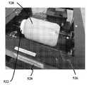
시험 고정물은 상기 유리 오버레이(128, 128a-h)를 시험하도록 고안되었다. 상기 고정물은 상기 유리 오버레이(128, 128a-h)가 모바일 장치(500, 500a) 커버 유리(502, 502a)로 매립되거나, 또는 커버 유리(502, 502a)로부터의 단계(510)에 의해 우묵해지거나 또는 커버 유리(502, 502a)(미도시)로부터 돌출되어 정렬될 수 있다. 통상적으로, 상기 오버레이(128, 128a-h) 삽입은 모바일 장치(500 500a) 커버 유리 (502, 502a)에 대해 우묵해지거나 또는 매립될 수 있다. 가속화된 시간 손상을 생성하고 필드 스크래치 이벤트를 모사하기 위하여, 고정물(500, 500a)에 마운트된 오버레이(128, 128a-h)를 45분 동안 텀블하였으며, 이는 필드에서 누적 손상의 1년 가치를 초과하여 대략 균등할 수 있다. 상기 텀블러는 유저의 주머니 또는 지갑에서 오버레이(128, 128a-h)에 의해 마주칠 수 있는 통상의 아이템(예를 들어, 집 열쇠, 펜, 동전, 화장품, 배지, 및 손톱 다듬는 줄)을 함유하였다. 도 15a 및 15b에 나타낸 바와 같이, 나사 톱 뚜껑(522)을 갖는 1 갤런의 NALGENETM 컨테이너(520)가 지갑 내용물 통상의 아이템(524)으로 채워지고 오버레이(128, 128a-h)가 고정물(500, 500a)에 마운트되었다(샘플). 상기 내용물 및 샘플을 갖는 Nalgene 용기(520)는 텀블 시험기(528)의 회전 실린더(526) 상에 위치되었다. 사용된 텀블 시험기(528)는 COVINGTON ENGINEERING (Redlands, CA)에 의해 제작된, 1/3 HP 모토를 갖는, COVINGTON_ROLL_N_TUMBLE MODEL #268이었다. 상기 시험은 40 RPM에서 수행되었다. NALGENETM 컨테이너(520)의 내부 직경에 부착된 핀(530)은 상기 텀블 시험기(528) 상에서 컨테이너(520)가 회전됨에 따라 컨테이너 내용물의 혼합을 제공하였다. 45분의 텀블링 및 12시간의 대기 기간 후, 상기 샘플을 시각적 외관에 대해서 그리고 스크래치 및 유리 균열과 같은 시각적 및 미시적 모든 손상에 대해서 시각적으로 그리고 현미경으로 검사하였다. 12시간의 대기 기간은 유리 오버레이(128, 128a-h)의 모든 지연 균열을 검출하기 위한 것이다.Test fixtures were designed to test the glass overlays 128, 128a-h. The fixture may have the
상기 시험 결과는 "시각적으로" 나타나는 균열 및 어떠한 표면 손상 없이 45분의 텀블링에서 유리 오버레이(128, 128a-h)가 생존하였음을 나타내었다. 육안으로 통상적으로 보여지지 않는 미세-연성 스크래치는 고 배율(30X) 하에서만 볼 수 있다.The test results indicated that the glass overlays 128, 128a-h survived the 45 minute tumbling without cracking and any surface damage appearing “visually”. Micro-ductile scratches not typically seen with the naked eye can only be seen under high magnification (30X).
상기 미세-연성 스크래치는 또한 공초점의 현미경 관찰에 의해 분석되었다. 상기 오버레이 유리(128, 128a-h) 상의 가장 심한 스크래치가 약 0.5 ㎛ 깊이 및 약 10 ㎛ 너비인 것으로 발견되었다. 대조적으로, 45분 텀블링 후 유사 영역의 소다 라임 유리 상의 표면 손상은 약 8 ㎛의 스크래치 깊이 및 약 200 ㎛의 스크래치 폭 및 측면 스크래치를 갖도록 가시적으로 손상되었다.The micro-soft scratches were also analyzed by microscopic observation of confocal. The most severe scratches on the
실시예 및 비교예Examples and Comparative Examples
P/d2로 정의된 표준화된 하중을 두 개의 종래 기술 참조에 대해 아래 표 1에 나타내며, 여기서 P는 고장에서의 펑크 하중이고, d는 초박형 오버레이의 두께이다. 참조 1에서 Chai 및 Lawn (2000)은 작업에서 연마된 유리를 사용하였다. 다른 구조체의 역학을 연구하는 종래 공보에서, Chai 및 Lawn (1999)은 참조 2에서 연마된 유리보다 더욱 강한 에칭된 유리를 사용하였다. Chai 및 Lawn (2000)에서 정의된 제형에 에칭된 유리의 강도를 적용하는 것은 P/d2<2000 N/mm2로서 종래 기술을 정의한다.The standardized load defined as P / d2 is shown in Table 1 below for two prior art references, where P is the puncture load at failure and d is the thickness of the ultra-thin overlay. In

다음의 표 2에 나타낸 예시적인 실험에서, 센서가 장치의 외부 밀봉의 부분이 되는 센서 커버 적용에 대하여, 1500 N/mm2의 P/d2에 대하여, 종래 기술은 0.125 mm 두께 유리를 요구하는 반면, 본 기재의 예시적인 구현예에 따르면, 단지 0.07 mm 두께 유리가 요구될 것이다. 두께에서 이러한 45% 감소는 센서의 신호 대 노이즈 비 상에 큰 충격을 가질 수 있다. 예를 들어 초-박형 오버레이는 최종 형상에 대해 부분을 절단하는 단계, 모든 이전의 흠결을 제거하기 위하여 유리를 에칭하는 단계, 이온-교환에 의해 초-박형 유리를 강화하는 단계, 이어서 이온-교환 공정 시 형성된 모든 새로운 흠결을 제거하기 위하여 2번 광 에칭하는 단계 및 보호층으로 감소된-흠결 표면을 보호하는 단계에 의해 제조되었으며, 여기서 상기 보호층은 라미네이트 층이었다. 여기서, 상기 광 에칭은 층의 이온-교환 깊이(DOL) 미만의 깊이까지 물질을 제거하는 광 화학적 에칭이다.In the example experiments shown in Table 2 below, for a sensor cover application where the sensor is part of the outer seal of the device, for a P / d2 of 1500 N / mm2 , the prior art requires 0.125 mm thick glass. In contrast, according to an exemplary embodiment of the present disclosure, only 0.07 mm thick glass will be required. This 45% reduction in thickness can have a large impact on the signal to noise ratio of the sensor. For example, ultra-thin overlays can be used to cut portions relative to the final shape, etch the glass to remove all previous defects, strengthen the ultra-thin glass by ion-exchange, and then ion-exchange. It was prepared by two light etching steps to remove all new defects formed in the process and protecting the reduced-defect surface with a protective layer, where the protective layer was a laminate layer. Here, the photoetch is a photochemical etch that removes material to a depth below the ion-exchange depth (DOL) of the layer.

예시적인 구현예 샘플 Ex-1 내지 Ex-8에서 광 에칭 처리(박형 에칭)는 B10 (고장 확률 분포의 10번째 백분위수)에서 3000 N/mm2 초과의 P/d2를 나타낸 한편, 처리 없이, 비교예 C-1 내지 C-7에서, P/d2은 3000 N/mm2 미만이었다.Exemplary Embodiments The photo etch treatment (thin etch) in Samples Ex-1 to Ex-8 shows P / d2 greater than 3000 N / mm2 at B10 (10th percentile of failure probability distribution), without treatment In Comparative Examples C-1 to C-7, P / d2 was less than 3000 N / mm2 .
상기 오버레이의 좀 더 낮은 두께는 좀 더 낮은 겉보기 두께를 가능하게 한다. 다음의 표 3은 종래 사용된 다양한 물질 및 두께를 나타낸다. 본원에 개시된 본 예시적인 구현예는 가장 낮은 겉보기 두께를 가능하게 한다.Lower thicknesses of the overlay allow for lower apparent thicknesses. Table 3 below shows the various materials and thicknesses conventionally used. The present exemplary embodiments disclosed herein allow for the lowest apparent thickness.

상기 연필 경도 시험은 다층 샘플에서 라미네이트된 유리 층(128, 128a-h)으로 수행되었다. 연필 경도에 대한 공정은 다음과 같다. BYK GARDNER®로부터의 연필 경도 시험기 PH5800는 시험을 위하여 연필 세트(9B 내지 9H)를 매칭하여 사용되었다. 상기 코팅은 다양한 크기 및 형상의 유리 플레이트 샘플 상에 코팅되고 경화되었으며, 일부 유리는 다른 적용의 기판을 모방하기 위하여 다른 화학물질로 예비-처리되었다. 상기 특정의 측정기는 ASTM D 3363 및 ISO 15184 검사 표준의 요구를 만족시키는 레벨 게이지 및 비중량을 갖는다. 상기 샘플을 데스크 상에 평탄하게 위치시키고 특정 연밀 경도를 갖는 측정기를 연필 팁이 상기 샘플을 터치할 때 상기 레벨 게이지가 평탄한 조건을 나타내는 위치에 놓았다. 다음으로 핸들을 갖는 측정기를 앞으로 밀어 연필이 적어도 1/2 인치의 거리를 가로질러 움직일 수 있도록 하였다. 표면 상에 가시적인 스크래치 선을 생성하지 않는 가장 큰 경도 등급 연필을 샘플의 연필 경도로서 배당하였다. 본 결과는 어떠한 관찰가능한 스크래치 없이 라미네이트된 샘플이 9H 연필 경도를 통과함을 나타내었다.The pencil hardness test was performed with laminated glass layers 128, 128a-h in a multilayer sample. The process for pencil hardness is as follows. Pencil hardness tester PH5800 from BYK GARDNER® was used to match the pencil sets 9B-9H for testing. The coating was coated and cured on glass plate samples of various sizes and shapes, and some glass was pre-treated with other chemicals to mimic substrates of different applications. This particular meter has a level gauge and specific weight that meets the requirements of ASTM D 3363 and ISO 15184 inspection standards. The sample was placed flat on the desk and a meter with a specific softness hardness was placed in a position where the level gauge indicated a flat condition when a pencil tip touched the sample. Next, the measuring instrument with the handle was pushed forward to allow the pencil to move across a distance of at least 1/2 inch. The largest hardness grade pencil that did not produce visible scratch lines on the surface was assigned as the pencil hardness of the sample. The results showed that the laminated sample passed the 9H pencil hardness without any observable scratch.
본 기재의 예시적인 구현예에 따르면, 상기 강화된 유리 커버는 50 ㎛ 미만의 유리 두께를 감소시킬 뿐 아니라 좀 더 나은 표면 보호를 제공하기 위하여 유기/무기질 코팅 스택을 대체할 수 있으며, 이는 20dB 초과에 의해 신호-대-잡음 비의 항으로 측정된 센서 성능 개선을 제공하는 한편, 유기 코팅 스택에 반대되는 좀 더 나은 스크래치 및 충격 저항성을 제공한다.According to an exemplary embodiment of the present disclosure, the tempered glass cover can replace organic / inorganic coating stacks to provide better surface protection as well as reduce glass thickness below 50 μm, which is greater than 20 dB It provides sensor performance improvement, measured in terms of signal-to-noise ratio, while providing better scratch and impact resistance as opposed to an organic coating stack.
당해 기술 분야의 통상의 기술자에게 다양한 변형 및 변화가 본 기재의 사상 또는 범위를 벗어나지 않고 본 기재에서 이루어질 수 있음이 명백할 것이다. 따라서, 본 기재는 첨부된 청구항 및 그 동등물의 범위 내에서 이루어는 한 본 기재의 변형 및 변화를 커버한다는 점이 의도된다.It will be apparent to those skilled in the art that various modifications and changes can be made in the present disclosure without departing from the spirit or scope of the disclosure. Accordingly, it is intended that this disclosure cover modifications and variations of this disclosure provided they come within the scope of the appended claims and their equivalents.
Claims (22)
Translated fromKorean250 마이크로미터 미만 두께의 유리 시트, 상기 유리 시트는 제1 및 제2의 템퍼 표면을 포함하며, 여기서 적어도 상기 제1의 템퍼 표면은 적어도 5 마이크로미터의 깊이를 갖는 표면 압축층 및 적어도 200 MPa의 표면 압축 응력을 포함함;
상기 제1의 템퍼 표면 상에 배치된 라미네이션 층; 및
기판 층을 포함하며,
여기서 상기 유리 시트 및 기판 층은 상기 라미네이션 층을 통해서 함께 라미네이트되며,
상기 다층 구조체의 유리 시트의 펑크 계수, Pf는 B10 (고장 확률 분포의 10번째 백분위수)에서 적어도 3000 N/mm2이며, 상기 펑크 계수는 상기 유리 시트의 두께 제곱에 대한 고장에서의 펑크 하중의 비이며, 여기서 펑크 계수는 상기 유리 시트의 적어도 하나의 템퍼 표면에 걸쳐 중심에 있는 1.5 mm의 직경 구형 세그먼트 팁 및 초당 약 30 뉴턴의 속도로 선형적으로 증가하는 하중에 의해 측정되는, 다층 구조체.As a multilayer structure,
A glass sheet less than 250 micrometers thick, the glass sheet comprising first and second temper surfaces, wherein at least the first temper surface has a surface compressive layer having a depth of at least 5 micrometers and at least 200 MPa Including surface compressive stresses;
A lamination layer disposed on the first temper surface; And
A substrate layer,
Wherein the glass sheet and substrate layer are laminated together through the lamination layer,
The puncture coefficient, Pf, of the glass sheet of the multilayer structure, is at least 3000 N / mm2 at B10 (10th percentile of failure probability distribution), and the puncture coefficient is the puncture load at failure to the thickness square of the glass sheet. Wherein the puncture coefficient is measured by a 1.5 mm diameter spherical segment tip centered over at least one temper surface of the glass sheet and a linearly increasing load at a rate of about 30 Newtons per second.
상기 라미네이션 층은 9 GPa 미만의 탄성 계수를 포함하며, 상기 라미네이션 층은 약 20 ㎛ 미만의 두께인, 다층 구조체.The method according to claim 1,
Wherein the lamination layer comprises an elastic modulus of less than 9 GPa and the lamination layer is less than about 20 μm thick.
상기 기판 층은 25 GPa 초과의 탄성 계수를 포함하는, 다층 구조체.The method according to claim 1,
And the substrate layer comprises a modulus of elasticity greater than 25 GPa.
상기 유리 시트 및 기판 층 사이에 배치된 전기적으로 전도성의 경로를 포함하는 전자 부품층을 더욱 포함하는, 다층 구조체.The method according to claim 1,
Further comprising an electronic component layer comprising an electrically conductive path disposed between the glass sheet and the substrate layer.
상기 라미네이션 층은 광학적으로 투명한, 다층 구조체.The method according to claim 1,
And the lamination layer is optically transparent.
상기 제2의 템퍼 표면은 적어도 10 마이크로미터의 깊이 및 적어도 200 MPa의 표면 압축 응력을 갖는 표면 압축층을 포함하며, 상기 제2의 템퍼 표면 압축 층 깊이는 상기 제1의 템퍼 표면 압축 층 깊이 미만인, 다층 구조체.The method according to claim 1,
The second temper surface comprises a surface compressive layer having a depth of at least 10 micrometers and a surface compressive stress of at least 200 MPa, wherein the second temper surface compressive layer depth is less than the first temper surface compressive layer depth , Multilayer structure.
상기 제2의 템퍼 표면은 상기 표면 압축 층의 깊이 미만으로 화학적으로 에칭되고 템퍼되는, 다층 구조체.The method according to claim 6,
And the second temper surface is chemically etched and tempered to less than the depth of the surface compression layer.
상기 제1의 템퍼 표면은 상기 표면 압축 층의 깊이 미만으로 화학적으로 에칭되고 템퍼되는, 다층 구조체.The method according to claim 1,
And the first temper surface is chemically etched and tempered to less than the depth of the surface compression layer.
상기 유리 시트는 0.014 mm 미만의 겉보기 두께, tapp를 포함하며, 상기 겉보기 두께는 유리 시트 유전 상수, k에 의해 나눠진 유리 시트 두께 t: tapp = t/k를 나타내며,
상기 다층 구조체 내의 유리 시트는 6H 초과의 연필 경도를 포함하며, 여기서 연필 경도는 ASTM D 3363 및 ISO 15184 검사 표준으로 측정되는, 다층 구조체.The method according to claim 1,
The glass sheet comprises an apparent thickness of less than 0.014 mm, tapp , wherein the apparent thickness represents a glass sheet thickness t divided by the glass sheet dielectric constant, k: tapp = t / k,
The glass sheet in the multilayer structure includes a pencil hardness of greater than 6H, wherein pencil hardness is measured by ASTM D 3363 and ISO 15184 inspection standards.
유리 물질의 유리 오버레이, 상기 유리 오버레이는 다음을 포함함:
서로 떨어진 제1 및 제2의 주표면, 및
상기 제1 및 제2의 주표면 사이의 250 마이크로미터 미만의 두께,
여기서, 상기 유리 오버레이는 적어도 상기 제1의 주표면 상에서 강화됨,
여기서, 상기 제1의 주표면에서의 압축 응력은 적어도 200 MPa임, 및
여기서 상기 압축 응력은 상기 제1의 주표면에서부터 적어도 5 마이크로미터인 층의 깊이까지 안쪽으로 연장함; 및
층들의 스택을 포함하는 언더레이를 포함하며,
여기서, 상기 언더레이의 제1의 층은 상기 유리 오버레이를 완충하도록 5 GPa 미만인 낮은 탄성 계수를 가지며,
여기서, 상기 언더레이의 제2의 층은 상기 제1의 층의 탄성 계수의 적어도 5배의 탄성 계수를 갖도록, 딱딱하며(stiff),
여기서, 상기 언더레이의 제1의 층은 상기 유리 오버레이 및 상기 언더레이의 제2의 층 사이에 있으며,
여기서, 상기 제1의 층은 200 마이크로미터 이하인, 상기 유리 오버레이 및 제2의 층 사이의 두께를 가지며, 상기 언더레이의 제1의 층 내로 상기 유리 오버레이의 과도한 굴절은 상기 언더레이의 제2의 층에 의해 억제되는, 보호 유리 시스템.As a protective glass system,
Glass overlay of glass material, wherein the glass overlay includes:
First and second major surfaces apart from each other, and
A thickness of less than 250 micrometers between the first and second major surfaces,
Wherein the glass overlay is strengthened on at least the first major surface,
Wherein the compressive stress at the first major surface is at least 200 MPa, and
Wherein the compressive stress extends inwardly from the first major surface to a depth of a layer that is at least 5 micrometers; And
An underlay comprising a stack of layers,
Wherein the first layer of the underlay has a low modulus of elasticity of less than 5 GPa to buffer the glass overlay,
Wherein the second layer of the underlay is stiff to have an elastic modulus of at least five times the elastic modulus of the first layer,
Wherein the first layer of the underlay is between the glass overlay and the second layer of the underlay,
Wherein the first layer has a thickness between the glass overlay and the second layer that is less than or equal to 200 micrometers, and wherein the excessive refraction of the glass overlay into the first layer of the underlay causes the second layer of the underlay to Protective glass system, suppressed by layers.
상기 유리 오버레이의 제1의 주표면은 광 에칭을 나타내는 표면 피쳐를 포함하는, 보호 유리 시스템.The method according to claim 10,
And the first major surface of the glass overlay comprises a surface feature indicative of photo etching.
상기 제1의 주표면은 1000Х 광학 현미경 검사 시 범프 및 스무드-롤링 핏 및 범프를 포함하며, 여기서 상기 핏 및 범프의 대부분은 서브미크론 크기이며, 1 마이크로미터 미만인 제1의 주표면의 인접 부분에 직각인 깊이 또는 높이를 갖는, 보호 유리 시스템.The method according to claim 11,
The first major surface comprises bumps and smooth-rolling fits and bumps upon 1000 435 optical microscopy, wherein the majority of the fits and bumps are submicron in size and adjacent to the first major surface of less than 1 micrometer. Protective glass system, having a right angle or depth.
상기 언더레이의 제3의 층은 전기적으로 전도성 경로를 포함하는 전자 부품을 포함하는, 보호 유리 시스템.The method according to claim 10,
And the third layer of the underlay comprises an electronic component comprising an electrically conductive path.
상기 제3의 층은 상기 유리 오버레이 및 제1의 층 사이에 위치된, 보호 유리 시스템.The method according to claim 13,
The third layer is located between the glass overlay and the first layer.
상기 유리 오버레이는 20 마이크로미터 이하의 초-저(ultra-low) 겉보기 두께 tapp 를 가지며, 겉보기 두께 tapp 는 상기 유리 물질의 유전 상수, k에 의해 나눈 두께 t이며, 상기 유리 오버레이를 통해서 상기 전자 부품에 정보 통신을 위한 신호-대-잡음 성능에 유용한, 보호 유리 시스템.The method according to claim 10,
The glass overlay has an ultra-low apparent thickness tapp of 20 micrometers or less, the apparent thickness tapp is the thickness t divided by the dielectric constant of the glass material, k, through the glass overlay A protective glass system, useful for signal-to-noise performance for telecommunications in electronic components.
상기 보호 유리 시스템은 B10 (고장 확률 분포의 10번째 백분위수)에서 적어도 3000 N/mm2의 펑크 계수, Pf를 가지며, 펑크 계수는 상기 유리 오버레이의 제2의 주표면에 걸쳐 중심에 있는 1.5 mm 직경 구형 세그먼트 팁 및 초 당 약 30 뉴턴의 속도로 선형적으로 증가하는 하중에 의해 측정되는, 보호 유리 시스템.The method according to claim 10,
The protective glass system has a puncture coefficient, Pf of at least 3000 N / mm2 at B10 (10th percentile of failure probability distribution), the puncture coefficient being 1.5 mm centered over the second major surface of the glass overlay. A protective glass system, measured by diameter spherical segment tips and a linearly increasing load at a rate of about 30 Newtons per second.
상기 유리 물질은 보로실리케이트 유리를 포함하는, 보호 유리 시스템.The method according to claim 10,
The glass material comprises borosilicate glass.
상기 유리 오버레이는 약 190 mJ의 평균 블런트 충격 접촉 에너지 및 120 mJ 초과의 확률 분포 블런트 충격 접촉 에너지의 10번째 백분위수 (B10)를 포함하며, 여기서 상기 블런트 충격 접촉 에너지는 상기 보호 유리 시스템에서 유리 오버레이 상에 직접 28 그램, 19.02 mm 직경 구를 낙하하여 측정되는, 보호 유리 시스템.The method according to claim 10,
The glass overlay includes a tenth percentile (B10) of an average blunt impact contact energy of about 190 mJ and a probability distribution blunt impact contact energy of greater than 120 mJ, wherein the blunt impact contact energy is a glass overlay in the protective glass system. A protective glass system, measured by dropping a 28 gram, 19.02 mm diameter sphere directly onto a phase.
청구항 10의 유리 시스템을 포함하며, 여기서 상기 유리 오버레이는 제2의 주표면 상에서 강화되며,
여기서, 상기 제2의 주표면에서의 압축 응력은 적어도 200 MPa이며,
여기서, 상기 압축 응력은 상기 제2의 주표면에서부터 적어도 10 마이크로미터인 층의 깊이까지 안쪽으로 연장하며,
여기서, 상기 압축 응력은 상기 제2의 주표면으로부터 상기 압축 응력이 상기 제1의 주표면으로부터 안쪽으로 연장하는 층의 깊이 미만인 층의 깊이까지 안쪽으로 연장하며,
여기서, 상기 제2의 주표면은 상기 모바일 장치의 디스플레이 커버 표면에서 오프닝을 통해서 노출되며,
여기서, 상기 제2의 주표면은 상기 디스플레이 커버 표면으로부터 약 100 내지 1200 마이크로미터 우묵한, 모바일 장치.As a mobile device,
The glass system of claim 10, wherein the glass overlay is reinforced on a second major surface,
Wherein the compressive stress at the second major surface is at least 200 MPa,
Wherein the compressive stress extends inwardly from the second major surface to a depth of a layer that is at least 10 micrometers,
Wherein the compressive stress extends inwardly from the second major surface to a depth of layer where the compressive stress is less than the depth of the layer extending inward from the first major surface,
Here, the second major surface is exposed through the opening on the display cover surface of the mobile device,
Wherein the second major surface is recessed from about 100 to 1200 microns from the display cover surface.
상기 유리 오버레이는 1.5 m 초과의 파괴 저항을 포함하며,
여기서 파괴 저항은 사포에 대해 평탄면(flat face) 배향으로 먼저, 그 다음으로 사포에 대해 30도 각의 배향으로 접착제 사포에 매립된 180 그릿 Al2O3에 의해 커버된 실질적으로 비-항복 표면 상에 약 130 g 디스플레이 커버 표면의 모바일 장치를 낙하시켜 측정된, 모바일 장치.The method according to claim 19,
The glass overlay includes a fracture resistance of more than 1.5 m,
Wherein the fracture resistance is a substantially non-yielding surface covered by 180 grit Al2 O3 embedded in adhesive sandpaper in a flat face orientation with respect to sandpaper and then in a 30 degree angle orientation with respect to sandpaper. A mobile device, measured by dropping a mobile device of about 130 g display cover surface onto it.
상기 유리 오버레이 제2의 주표면은 45분 초과의 텀블 저항(tumble resistance)을 포함하며, 여기서 텀블 저항은 집 열쇠, 동전, 화장품 케이스, 및 손톱 다듬는 줄과 함께 상기 모바일 장치를 텀블링하는 단계, 상기 텀블링을 멈춘 후 12시간 기다리는 단계 및 상기 제2의 주표면에서 모든 유리 균열을 현미경으로 검사하는 단계에 의해 측정되며,
여기서 45분은 1년의 인-서비스(in-service) 누적 손상과 대략 균등한, 모바일 장치.The method according to claim 19,
The glass overlay second major surface includes tumble resistance of more than 45 minutes, wherein the tumble resistance includes tumbling the mobile device with a house key, a coin, a cosmetic case, and a nail file; Waiting by 12 hours after stopping tumbling and microscopic examination of all glass cracks on the second major surface,
Where 45 minutes is approximately equal to one year of in-service cumulative damage.
상기 방법은:
유리 시트의 적어도 하나의 주표면을 이온-교환 템퍼링하는 단계;
상기 이온-교환 템퍼링 후, 상기 적어도 하나의 주표면을 광 에칭하여 표면 흠결을 제거하는 단계;
상기 적어도 하나의 템퍼되고 광 에칭된 표면 중 하나 상에 라미네이트 층을 증착하는 단계; 및
상기 라미네이트 층 상에 기판 층을 증착하여 상기 유리 시트 및 기판을 함께 라미네이트하는 단계를 포함하며,
여기서 상기 다층 구조체 내의 유리 시트의 펑크 계수, Pf는 B10 (고장 확률 분포의 10번째 백분위수)에서 적어도 3000 N/mm2이며, 상기 펑크 계수는 상기 유리 시트의 두께 제곱에 대한 고장에서의 펑크 하중의 비이며, 펑크 계수는 상기 유리 시트의 적어도 하나의 주표면에 걸쳐 중심에 있는 1.5 mm의 직경 구형 세그먼트 팁 및 초당 약 30 뉴턴의 속도로 선형적으로 증가하는 하중에 의해 측정되는, 다층 구조체의 제조방법.As a method of manufacturing a multilayer structure,
The method is:
Ion-exchanging tempering at least one major surface of the glass sheet;
After the ion-exchange tempering, photo etching the at least one major surface to remove surface defects;
Depositing a laminate layer on one of the at least one tempered and photo etched surface; And
Depositing a substrate layer on the laminate layer to laminate the glass sheet and substrate together,
Wherein the puncture coefficient, Pf, of the glass sheet in the multilayer structure is at least 3000 N / mm2 at B10 (10th percentile of failure probability distribution), and the puncture coefficient is a puncture load at failure with respect to the thickness square of the glass sheet. And the puncture coefficient of the multilayer structure is measured by a 1.5 mm diameter spherical segment tip centered over at least one major surface of the glass sheet and a linearly increasing load at a rate of about 30 Newtons per second. Manufacturing method.
Applications Claiming Priority (3)
| Application Number | Priority Date | Filing Date | Title |
|---|---|---|---|
| US201762481387P | 2017-04-04 | 2017-04-04 | |
| US62/481,387 | 2017-04-04 | ||
| PCT/US2018/025975WO2018187391A1 (en) | 2017-04-04 | 2018-04-04 | Multi-layer structure and method of making same |
Publications (2)
| Publication Number | Publication Date |
|---|---|
| KR20190136052Atrue KR20190136052A (en) | 2019-12-09 |
| KR102451062B1 KR102451062B1 (en) | 2022-10-05 |
Family
ID=63712988
Family Applications (1)
| Application Number | Title | Priority Date | Filing Date |
|---|---|---|---|
| KR1020197032384AActiveKR102451062B1 (en) | 2017-04-04 | 2018-04-04 | Multilayer structure and manufacturing method thereof |
Country Status (6)
| Country | Link |
|---|---|
| US (1) | US11591257B2 (en) |
| EP (1) | EP3606881A4 (en) |
| JP (1) | JP7329448B2 (en) |
| KR (1) | KR102451062B1 (en) |
| CN (1) | CN110691761B (en) |
| WO (1) | WO2018187391A1 (en) |
Families Citing this family (4)
| Publication number | Priority date | Publication date | Assignee | Title |
|---|---|---|---|---|
| KR20220159254A (en)* | 2020-03-27 | 2022-12-02 | 보에 테크놀로지 그룹 컴퍼니 리미티드 | Flexible display devices and electronic devices |
| WO2022005890A1 (en)* | 2020-07-01 | 2022-01-06 | Corning Incorporated | Functional laminated glass articles and methods of making the same |
| CN113257129B (en)* | 2021-05-13 | 2023-06-09 | 京东方科技集团股份有限公司 | Flexible cover plate and preparation method thereof, display panel and preparation method thereof |
| CN114885559B (en)* | 2022-03-29 | 2024-05-14 | 京东方科技集团股份有限公司 | Display cover plate, method for manufacturing display cover plate and display device |
Citations (4)
| Publication number | Priority date | Publication date | Assignee | Title |
|---|---|---|---|---|
| KR100855416B1 (en)* | 2000-09-28 | 2008-08-29 | 솔루티아인코포레이티드 | Intrusion-proof glass laminate |
| KR20150036443A (en)* | 2012-08-07 | 2015-04-07 | 애플 인크. | Flexible displays |
| WO2016073549A1 (en)* | 2014-11-05 | 2016-05-12 | Corning Incorporated | Glass articles with non-planar features and alkali-free glass elements |
| KR20160061326A (en)* | 2014-01-29 | 2016-05-31 | 코닝 인코포레이티드 | Bendable glass stack assemblies, articles and methods of making the same |
Family Cites Families (26)
| Publication number | Priority date | Publication date | Assignee | Title |
|---|---|---|---|---|
| US5963679A (en) | 1996-01-26 | 1999-10-05 | Harris Corporation | Electric field fingerprint sensor apparatus and related methods |
| US5920640A (en) | 1997-05-16 | 1999-07-06 | Harris Corporation | Fingerprint sensor and token reader and associated methods |
| NO315017B1 (en) | 2000-06-09 | 2003-06-23 | Idex Asa | Sensor chip, especially for measuring structures in a finger surface |
| WO2011044295A2 (en) | 2009-10-07 | 2011-04-14 | Hologic, Inc. | Processing and displaying computer-aided detection information associated with breast x-ray images |
| JP2013516387A (en) | 2010-01-07 | 2013-05-13 | コーニング インコーポレイテッド | Shock-resistant glass plate |
| US20130059157A1 (en)* | 2010-05-28 | 2013-03-07 | Dana Craig Bookbinder | Transparent laminates comprising intermediate or anomalous glass |
| US9516149B2 (en) | 2011-09-29 | 2016-12-06 | Apple Inc. | Multi-layer transparent structures for electronic device housings |
| US9030440B2 (en) | 2012-05-18 | 2015-05-12 | Apple Inc. | Capacitive sensor packaging |
| JP2016526003A (en) | 2013-05-23 | 2016-09-01 | コーニング インコーポレイテッド | Glass-coating laminate having controlled breaking strength |
| CN105682921B (en)* | 2013-08-30 | 2018-10-19 | 康宁股份有限公司 | Lightweight, high rigidity glass laminated structure |
| US10160688B2 (en) | 2013-09-13 | 2018-12-25 | Corning Incorporated | Fracture-resistant layered-substrates and articles including the same |
| US9527769B2 (en)* | 2013-10-09 | 2016-12-27 | Corning Incorporated | Reverse photochromic borosilicate glasses |
| KR102302163B1 (en)* | 2013-10-14 | 2021-09-15 | 코닝 인코포레이티드 | Ion Exchange Processes and Chemically Strengthened Glass Substrates Resulting Therefrom |
| US9588547B2 (en)* | 2014-03-27 | 2017-03-07 | Nlu Products, L.L.C. | Mobile device screen protector installation tray and system |
| US9315108B2 (en) | 2014-07-08 | 2016-04-19 | Toyota Jidosha Kabushiki Kaisha | Vehicle function determination |
| WO2016028542A1 (en)* | 2014-08-19 | 2016-02-25 | Corning Incorporated | Bendable glass stack assemblies and methods of making the same |
| US9477334B2 (en)* | 2014-10-31 | 2016-10-25 | Buwon Precision Sciences Co., Ltd. | Curved touch panel and method for fabricating the same |
| JP6849591B2 (en) | 2014-11-04 | 2021-03-24 | コーニング インコーポレイテッド | Flexible glass articles with non-alkali glass elements |
| CN107531550A (en)* | 2015-03-31 | 2018-01-02 | 科立视材料科技有限公司 | Glass composition of chemically strengthened alkali aluminoborosilicate glass having low dielectric constant |
| JP6768009B2 (en)* | 2015-06-02 | 2020-10-14 | コーニング インコーポレイテッド | Glass laminate with panes having a glass-glass laminate structure |
| US9701569B2 (en)* | 2015-07-21 | 2017-07-11 | Corning Incorporated | Glass articles exhibiting improved fracture performance |
| JPWO2017026267A1 (en) | 2015-08-11 | 2018-06-07 | 旭硝子株式会社 | Chemically tempered glass |
| JP6886460B2 (en) | 2015-10-13 | 2021-06-16 | コーニング インコーポレイテッド | Flexible electronic device module, article and its manufacturing method |
| EP3402667A1 (en) | 2016-01-15 | 2018-11-21 | Corning Incorporated | Foldable electronic device assemblies and cover elements for the same |
| KR102233720B1 (en)* | 2016-03-17 | 2021-03-30 | 코닝 인코포레이티드 | Bendable electronic device modules, articles, and bonding methods to form the same |
| US10198040B2 (en)* | 2016-05-20 | 2019-02-05 | Apple Inc. | Electronic devices with flexible displays |
- 2018
- 2018-04-04CNCN201880036093.XApatent/CN110691761B/enactiveActive
- 2018-04-04USUS16/500,997patent/US11591257B2/enactiveActive
- 2018-04-04EPEP18780636.9Apatent/EP3606881A4/ennot_activeWithdrawn
- 2018-04-04KRKR1020197032384Apatent/KR102451062B1/enactiveActive
- 2018-04-04WOPCT/US2018/025975patent/WO2018187391A1/ennot_activeCeased
- 2018-04-04JPJP2019554817Apatent/JP7329448B2/enactiveActive
Patent Citations (4)
| Publication number | Priority date | Publication date | Assignee | Title |
|---|---|---|---|---|
| KR100855416B1 (en)* | 2000-09-28 | 2008-08-29 | 솔루티아인코포레이티드 | Intrusion-proof glass laminate |
| KR20150036443A (en)* | 2012-08-07 | 2015-04-07 | 애플 인크. | Flexible displays |
| KR20160061326A (en)* | 2014-01-29 | 2016-05-31 | 코닝 인코포레이티드 | Bendable glass stack assemblies, articles and methods of making the same |
| WO2016073549A1 (en)* | 2014-11-05 | 2016-05-12 | Corning Incorporated | Glass articles with non-planar features and alkali-free glass elements |
Also Published As
| Publication number | Publication date |
|---|---|
| WO2018187391A1 (en) | 2018-10-11 |
| CN110691761A (en) | 2020-01-14 |
| EP3606881A4 (en) | 2021-01-06 |
| US20200031710A1 (en) | 2020-01-30 |
| EP3606881A1 (en) | 2020-02-12 |
| US11591257B2 (en) | 2023-02-28 |
| KR102451062B1 (en) | 2022-10-05 |
| CN110691761B (en) | 2022-03-29 |
| JP2020515503A (en) | 2020-05-28 |
| JP7329448B2 (en) | 2023-08-18 |
Similar Documents
| Publication | Publication Date | Title |
|---|---|---|
| KR102451062B1 (en) | Multilayer structure and manufacturing method thereof | |
| US10556825B2 (en) | Strengthened glass with deep depth of compression | |
| US11746046B2 (en) | Strengthened glass with ultra deep depth of compression | |
| EP3157880B1 (en) | Strengthened glass with deep depth of compression | |
| CN106604900B (en) | Method and apparatus for mitigating strength and/or strain loss in coated glass | |
| KR20180083907A (en) | Display Screen Protector | |
| US11236016B2 (en) | Chemically strengthened glass | |
| TW201930219A (en) | Hydrogen-containing glass-based articles with high indentation cracking threshold |
Legal Events
| Date | Code | Title | Description |
|---|---|---|---|
| PA0105 | International application | Patent event date:20191031 Patent event code:PA01051R01D Comment text:International Patent Application | |
| PG1501 | Laying open of application | ||
| A201 | Request for examination | ||
| PA0201 | Request for examination | Patent event code:PA02012R01D Patent event date:20210323 Comment text:Request for Examination of Application | |
| E902 | Notification of reason for refusal | ||
| PE0902 | Notice of grounds for rejection | Comment text:Notification of reason for refusal Patent event date:20220127 Patent event code:PE09021S01D | |
| E701 | Decision to grant or registration of patent right | ||
| PE0701 | Decision of registration | Patent event code:PE07011S01D Comment text:Decision to Grant Registration Patent event date:20220920 | |
| GRNT | Written decision to grant | ||
| PR0701 | Registration of establishment | Comment text:Registration of Establishment Patent event date:20220929 Patent event code:PR07011E01D | |
| PR1002 | Payment of registration fee | Payment date:20220930 End annual number:3 Start annual number:1 | |
| PG1601 | Publication of registration | ||
| PR1001 | Payment of annual fee | Payment date:20250625 Start annual number:4 End annual number:4 |