KR20190132362A - Heart valve sealing device and delivery device therefor - Google Patents
Heart valve sealing device and delivery device thereforDownload PDFInfo
- Publication number
- KR20190132362A KR20190132362AKR1020197025652AKR20197025652AKR20190132362AKR 20190132362 AKR20190132362 AKR 20190132362AKR 1020197025652 AKR1020197025652 AKR 1020197025652AKR 20197025652 AKR20197025652 AKR 20197025652AKR 20190132362 AKR20190132362 AKR 20190132362A
- Authority
- KR
- South Korea
- Prior art keywords
- paddle
- valve repair
- valve
- repair device
- paddles
- Prior art date
- Legal status (The legal status is an assumption and is not a legal conclusion. Google has not performed a legal analysis and makes no representation as to the accuracy of the status listed.)
- Granted
Links
Images


Classifications
- A—HUMAN NECESSITIES
- A61—MEDICAL OR VETERINARY SCIENCE; HYGIENE
- A61F—FILTERS IMPLANTABLE INTO BLOOD VESSELS; PROSTHESES; DEVICES PROVIDING PATENCY TO, OR PREVENTING COLLAPSING OF, TUBULAR STRUCTURES OF THE BODY, e.g. STENTS; ORTHOPAEDIC, NURSING OR CONTRACEPTIVE DEVICES; FOMENTATION; TREATMENT OR PROTECTION OF EYES OR EARS; BANDAGES, DRESSINGS OR ABSORBENT PADS; FIRST-AID KITS
- A61F2/00—Filters implantable into blood vessels; Prostheses, i.e. artificial substitutes or replacements for parts of the body; Appliances for connecting them with the body; Devices providing patency to, or preventing collapsing of, tubular structures of the body, e.g. stents
- A61F2/02—Prostheses implantable into the body
- A61F2/24—Heart valves ; Vascular valves, e.g. venous valves; Heart implants, e.g. passive devices for improving the function of the native valve or the heart muscle; Transmyocardial revascularisation [TMR] devices; Valves implantable in the body
- A61F2/2442—Annuloplasty rings or inserts for correcting the valve shape; Implants for improving the function of a native heart valve
- A61F2/246—Devices for obstructing a leak through a native valve in a closed condition
- A—HUMAN NECESSITIES
- A61—MEDICAL OR VETERINARY SCIENCE; HYGIENE
- A61B—DIAGNOSIS; SURGERY; IDENTIFICATION
- A61B17/00—Surgical instruments, devices or methods
- A—HUMAN NECESSITIES
- A61—MEDICAL OR VETERINARY SCIENCE; HYGIENE
- A61B—DIAGNOSIS; SURGERY; IDENTIFICATION
- A61B17/00—Surgical instruments, devices or methods
- A61B17/00234—Surgical instruments, devices or methods for minimally invasive surgery
- A—HUMAN NECESSITIES
- A61—MEDICAL OR VETERINARY SCIENCE; HYGIENE
- A61B—DIAGNOSIS; SURGERY; IDENTIFICATION
- A61B17/00—Surgical instruments, devices or methods
- A61B17/04—Surgical instruments, devices or methods for suturing wounds; Holders or packages for needles or suture materials
- A61B17/0469—Suturing instruments for use in minimally invasive surgery, e.g. endoscopic surgery
- A—HUMAN NECESSITIES
- A61—MEDICAL OR VETERINARY SCIENCE; HYGIENE
- A61B—DIAGNOSIS; SURGERY; IDENTIFICATION
- A61B17/00—Surgical instruments, devices or methods
- A61B17/34—Trocars; Puncturing needles
- A61B17/3468—Trocars; Puncturing needles for implanting or removing devices, e.g. prostheses, implants, seeds, wires
- A—HUMAN NECESSITIES
- A61—MEDICAL OR VETERINARY SCIENCE; HYGIENE
- A61F—FILTERS IMPLANTABLE INTO BLOOD VESSELS; PROSTHESES; DEVICES PROVIDING PATENCY TO, OR PREVENTING COLLAPSING OF, TUBULAR STRUCTURES OF THE BODY, e.g. STENTS; ORTHOPAEDIC, NURSING OR CONTRACEPTIVE DEVICES; FOMENTATION; TREATMENT OR PROTECTION OF EYES OR EARS; BANDAGES, DRESSINGS OR ABSORBENT PADS; FIRST-AID KITS
- A61F2/00—Filters implantable into blood vessels; Prostheses, i.e. artificial substitutes or replacements for parts of the body; Appliances for connecting them with the body; Devices providing patency to, or preventing collapsing of, tubular structures of the body, e.g. stents
- A61F2/02—Prostheses implantable into the body
- A61F2/24—Heart valves ; Vascular valves, e.g. venous valves; Heart implants, e.g. passive devices for improving the function of the native valve or the heart muscle; Transmyocardial revascularisation [TMR] devices; Valves implantable in the body
- A61F2/2409—Support rings therefor, e.g. for connecting valves to tissue
- A—HUMAN NECESSITIES
- A61—MEDICAL OR VETERINARY SCIENCE; HYGIENE
- A61F—FILTERS IMPLANTABLE INTO BLOOD VESSELS; PROSTHESES; DEVICES PROVIDING PATENCY TO, OR PREVENTING COLLAPSING OF, TUBULAR STRUCTURES OF THE BODY, e.g. STENTS; ORTHOPAEDIC, NURSING OR CONTRACEPTIVE DEVICES; FOMENTATION; TREATMENT OR PROTECTION OF EYES OR EARS; BANDAGES, DRESSINGS OR ABSORBENT PADS; FIRST-AID KITS
- A61F2/00—Filters implantable into blood vessels; Prostheses, i.e. artificial substitutes or replacements for parts of the body; Appliances for connecting them with the body; Devices providing patency to, or preventing collapsing of, tubular structures of the body, e.g. stents
- A61F2/02—Prostheses implantable into the body
- A61F2/24—Heart valves ; Vascular valves, e.g. venous valves; Heart implants, e.g. passive devices for improving the function of the native valve or the heart muscle; Transmyocardial revascularisation [TMR] devices; Valves implantable in the body
- A61F2/2412—Heart valves ; Vascular valves, e.g. venous valves; Heart implants, e.g. passive devices for improving the function of the native valve or the heart muscle; Transmyocardial revascularisation [TMR] devices; Valves implantable in the body with soft flexible valve members, e.g. tissue valves shaped like natural valves
- A61F2/2418—Scaffolds therefor, e.g. support stents
- A—HUMAN NECESSITIES
- A61—MEDICAL OR VETERINARY SCIENCE; HYGIENE
- A61F—FILTERS IMPLANTABLE INTO BLOOD VESSELS; PROSTHESES; DEVICES PROVIDING PATENCY TO, OR PREVENTING COLLAPSING OF, TUBULAR STRUCTURES OF THE BODY, e.g. STENTS; ORTHOPAEDIC, NURSING OR CONTRACEPTIVE DEVICES; FOMENTATION; TREATMENT OR PROTECTION OF EYES OR EARS; BANDAGES, DRESSINGS OR ABSORBENT PADS; FIRST-AID KITS
- A61F2/00—Filters implantable into blood vessels; Prostheses, i.e. artificial substitutes or replacements for parts of the body; Appliances for connecting them with the body; Devices providing patency to, or preventing collapsing of, tubular structures of the body, e.g. stents
- A61F2/02—Prostheses implantable into the body
- A61F2/24—Heart valves ; Vascular valves, e.g. venous valves; Heart implants, e.g. passive devices for improving the function of the native valve or the heart muscle; Transmyocardial revascularisation [TMR] devices; Valves implantable in the body
- A61F2/2427—Devices for manipulating or deploying heart valves during implantation
- A61F2/243—Deployment by mechanical expansion
- A—HUMAN NECESSITIES
- A61—MEDICAL OR VETERINARY SCIENCE; HYGIENE
- A61F—FILTERS IMPLANTABLE INTO BLOOD VESSELS; PROSTHESES; DEVICES PROVIDING PATENCY TO, OR PREVENTING COLLAPSING OF, TUBULAR STRUCTURES OF THE BODY, e.g. STENTS; ORTHOPAEDIC, NURSING OR CONTRACEPTIVE DEVICES; FOMENTATION; TREATMENT OR PROTECTION OF EYES OR EARS; BANDAGES, DRESSINGS OR ABSORBENT PADS; FIRST-AID KITS
- A61F2/00—Filters implantable into blood vessels; Prostheses, i.e. artificial substitutes or replacements for parts of the body; Appliances for connecting them with the body; Devices providing patency to, or preventing collapsing of, tubular structures of the body, e.g. stents
- A61F2/02—Prostheses implantable into the body
- A61F2/24—Heart valves ; Vascular valves, e.g. venous valves; Heart implants, e.g. passive devices for improving the function of the native valve or the heart muscle; Transmyocardial revascularisation [TMR] devices; Valves implantable in the body
- A61F2/2442—Annuloplasty rings or inserts for correcting the valve shape; Implants for improving the function of a native heart valve
- A61F2/2445—Annuloplasty rings in direct contact with the valve annulus
- A—HUMAN NECESSITIES
- A61—MEDICAL OR VETERINARY SCIENCE; HYGIENE
- A61F—FILTERS IMPLANTABLE INTO BLOOD VESSELS; PROSTHESES; DEVICES PROVIDING PATENCY TO, OR PREVENTING COLLAPSING OF, TUBULAR STRUCTURES OF THE BODY, e.g. STENTS; ORTHOPAEDIC, NURSING OR CONTRACEPTIVE DEVICES; FOMENTATION; TREATMENT OR PROTECTION OF EYES OR EARS; BANDAGES, DRESSINGS OR ABSORBENT PADS; FIRST-AID KITS
- A61F2/00—Filters implantable into blood vessels; Prostheses, i.e. artificial substitutes or replacements for parts of the body; Appliances for connecting them with the body; Devices providing patency to, or preventing collapsing of, tubular structures of the body, e.g. stents
- A61F2/02—Prostheses implantable into the body
- A61F2/24—Heart valves ; Vascular valves, e.g. venous valves; Heart implants, e.g. passive devices for improving the function of the native valve or the heart muscle; Transmyocardial revascularisation [TMR] devices; Valves implantable in the body
- A61F2/2442—Annuloplasty rings or inserts for correcting the valve shape; Implants for improving the function of a native heart valve
- A61F2/2454—Means for preventing inversion of the valve leaflets, e.g. chordae tendineae prostheses
- A61F2/2457—Chordae tendineae prostheses
- A—HUMAN NECESSITIES
- A61—MEDICAL OR VETERINARY SCIENCE; HYGIENE
- A61L—METHODS OR APPARATUS FOR STERILISING MATERIALS OR OBJECTS IN GENERAL; DISINFECTION, STERILISATION OR DEODORISATION OF AIR; CHEMICAL ASPECTS OF BANDAGES, DRESSINGS, ABSORBENT PADS OR SURGICAL ARTICLES; MATERIALS FOR BANDAGES, DRESSINGS, ABSORBENT PADS OR SURGICAL ARTICLES
- A61L27/00—Materials for grafts or prostheses or for coating grafts or prostheses
- A61L27/02—Inorganic materials
- A61L27/04—Metals or alloys
- A—HUMAN NECESSITIES
- A61—MEDICAL OR VETERINARY SCIENCE; HYGIENE
- A61L—METHODS OR APPARATUS FOR STERILISING MATERIALS OR OBJECTS IN GENERAL; DISINFECTION, STERILISATION OR DEODORISATION OF AIR; CHEMICAL ASPECTS OF BANDAGES, DRESSINGS, ABSORBENT PADS OR SURGICAL ARTICLES; MATERIALS FOR BANDAGES, DRESSINGS, ABSORBENT PADS OR SURGICAL ARTICLES
- A61L27/00—Materials for grafts or prostheses or for coating grafts or prostheses
- A61L27/50—Materials characterised by their function or physical properties, e.g. injectable or lubricating compositions, shape-memory materials, surface modified materials
- A61L27/56—Porous materials, e.g. foams or sponges
- A—HUMAN NECESSITIES
- A61—MEDICAL OR VETERINARY SCIENCE; HYGIENE
- A61B—DIAGNOSIS; SURGERY; IDENTIFICATION
- A61B17/00—Surgical instruments, devices or methods
- A61B17/0057—Implements for plugging an opening in the wall of a hollow or tubular organ, e.g. for sealing a vessel puncture or closing a cardiac septal defect
- A—HUMAN NECESSITIES
- A61—MEDICAL OR VETERINARY SCIENCE; HYGIENE
- A61B—DIAGNOSIS; SURGERY; IDENTIFICATION
- A61B17/00—Surgical instruments, devices or methods
- A61B17/04—Surgical instruments, devices or methods for suturing wounds; Holders or packages for needles or suture materials
- A61B17/0401—Suture anchors, buttons or pledgets, i.e. means for attaching sutures to bone, cartilage or soft tissue; Instruments for applying or removing suture anchors
- A—HUMAN NECESSITIES
- A61—MEDICAL OR VETERINARY SCIENCE; HYGIENE
- A61B—DIAGNOSIS; SURGERY; IDENTIFICATION
- A61B17/00—Surgical instruments, devices or methods
- A61B17/00234—Surgical instruments, devices or methods for minimally invasive surgery
- A61B2017/00238—Type of minimally invasive operation
- A61B2017/00243—Type of minimally invasive operation cardiac
- A—HUMAN NECESSITIES
- A61—MEDICAL OR VETERINARY SCIENCE; HYGIENE
- A61B—DIAGNOSIS; SURGERY; IDENTIFICATION
- A61B17/00—Surgical instruments, devices or methods
- A61B2017/00535—Surgical instruments, devices or methods pneumatically or hydraulically operated
- A61B2017/00557—Surgical instruments, devices or methods pneumatically or hydraulically operated inflatable
- A—HUMAN NECESSITIES
- A61—MEDICAL OR VETERINARY SCIENCE; HYGIENE
- A61B—DIAGNOSIS; SURGERY; IDENTIFICATION
- A61B17/00—Surgical instruments, devices or methods
- A61B2017/00743—Type of operation; Specification of treatment sites
- A61B2017/00778—Operations on blood vessels
- A61B2017/00783—Valvuloplasty
- A—HUMAN NECESSITIES
- A61—MEDICAL OR VETERINARY SCIENCE; HYGIENE
- A61B—DIAGNOSIS; SURGERY; IDENTIFICATION
- A61B17/00—Surgical instruments, devices or methods
- A61B2017/00831—Material properties
- A61B2017/00867—Material properties shape memory effect
- A—HUMAN NECESSITIES
- A61—MEDICAL OR VETERINARY SCIENCE; HYGIENE
- A61B—DIAGNOSIS; SURGERY; IDENTIFICATION
- A61B17/00—Surgical instruments, devices or methods
- A61B17/04—Surgical instruments, devices or methods for suturing wounds; Holders or packages for needles or suture materials
- A61B17/0401—Suture anchors, buttons or pledgets, i.e. means for attaching sutures to bone, cartilage or soft tissue; Instruments for applying or removing suture anchors
- A61B2017/0464—Suture anchors, buttons or pledgets, i.e. means for attaching sutures to bone, cartilage or soft tissue; Instruments for applying or removing suture anchors for soft tissue
- A—HUMAN NECESSITIES
- A61—MEDICAL OR VETERINARY SCIENCE; HYGIENE
- A61F—FILTERS IMPLANTABLE INTO BLOOD VESSELS; PROSTHESES; DEVICES PROVIDING PATENCY TO, OR PREVENTING COLLAPSING OF, TUBULAR STRUCTURES OF THE BODY, e.g. STENTS; ORTHOPAEDIC, NURSING OR CONTRACEPTIVE DEVICES; FOMENTATION; TREATMENT OR PROTECTION OF EYES OR EARS; BANDAGES, DRESSINGS OR ABSORBENT PADS; FIRST-AID KITS
- A61F2/00—Filters implantable into blood vessels; Prostheses, i.e. artificial substitutes or replacements for parts of the body; Appliances for connecting them with the body; Devices providing patency to, or preventing collapsing of, tubular structures of the body, e.g. stents
- A61F2/02—Prostheses implantable into the body
- A61F2/24—Heart valves ; Vascular valves, e.g. venous valves; Heart implants, e.g. passive devices for improving the function of the native valve or the heart muscle; Transmyocardial revascularisation [TMR] devices; Valves implantable in the body
- A61F2/2427—Devices for manipulating or deploying heart valves during implantation
- A—HUMAN NECESSITIES
- A61—MEDICAL OR VETERINARY SCIENCE; HYGIENE
- A61F—FILTERS IMPLANTABLE INTO BLOOD VESSELS; PROSTHESES; DEVICES PROVIDING PATENCY TO, OR PREVENTING COLLAPSING OF, TUBULAR STRUCTURES OF THE BODY, e.g. STENTS; ORTHOPAEDIC, NURSING OR CONTRACEPTIVE DEVICES; FOMENTATION; TREATMENT OR PROTECTION OF EYES OR EARS; BANDAGES, DRESSINGS OR ABSORBENT PADS; FIRST-AID KITS
- A61F2/00—Filters implantable into blood vessels; Prostheses, i.e. artificial substitutes or replacements for parts of the body; Appliances for connecting them with the body; Devices providing patency to, or preventing collapsing of, tubular structures of the body, e.g. stents
- A61F2/02—Prostheses implantable into the body
- A61F2/24—Heart valves ; Vascular valves, e.g. venous valves; Heart implants, e.g. passive devices for improving the function of the native valve or the heart muscle; Transmyocardial revascularisation [TMR] devices; Valves implantable in the body
- A61F2/2442—Annuloplasty rings or inserts for correcting the valve shape; Implants for improving the function of a native heart valve
- A61F2/2454—Means for preventing inversion of the valve leaflets, e.g. chordae tendineae prostheses
- A—HUMAN NECESSITIES
- A61—MEDICAL OR VETERINARY SCIENCE; HYGIENE
- A61F—FILTERS IMPLANTABLE INTO BLOOD VESSELS; PROSTHESES; DEVICES PROVIDING PATENCY TO, OR PREVENTING COLLAPSING OF, TUBULAR STRUCTURES OF THE BODY, e.g. STENTS; ORTHOPAEDIC, NURSING OR CONTRACEPTIVE DEVICES; FOMENTATION; TREATMENT OR PROTECTION OF EYES OR EARS; BANDAGES, DRESSINGS OR ABSORBENT PADS; FIRST-AID KITS
- A61F2/00—Filters implantable into blood vessels; Prostheses, i.e. artificial substitutes or replacements for parts of the body; Appliances for connecting them with the body; Devices providing patency to, or preventing collapsing of, tubular structures of the body, e.g. stents
- A61F2/02—Prostheses implantable into the body
- A61F2/24—Heart valves ; Vascular valves, e.g. venous valves; Heart implants, e.g. passive devices for improving the function of the native valve or the heart muscle; Transmyocardial revascularisation [TMR] devices; Valves implantable in the body
- A61F2/2442—Annuloplasty rings or inserts for correcting the valve shape; Implants for improving the function of a native heart valve
- A61F2/2463—Implants forming part of the valve leaflets
- A—HUMAN NECESSITIES
- A61—MEDICAL OR VETERINARY SCIENCE; HYGIENE
- A61F—FILTERS IMPLANTABLE INTO BLOOD VESSELS; PROSTHESES; DEVICES PROVIDING PATENCY TO, OR PREVENTING COLLAPSING OF, TUBULAR STRUCTURES OF THE BODY, e.g. STENTS; ORTHOPAEDIC, NURSING OR CONTRACEPTIVE DEVICES; FOMENTATION; TREATMENT OR PROTECTION OF EYES OR EARS; BANDAGES, DRESSINGS OR ABSORBENT PADS; FIRST-AID KITS
- A61F2/00—Filters implantable into blood vessels; Prostheses, i.e. artificial substitutes or replacements for parts of the body; Appliances for connecting them with the body; Devices providing patency to, or preventing collapsing of, tubular structures of the body, e.g. stents
- A61F2/02—Prostheses implantable into the body
- A61F2/24—Heart valves ; Vascular valves, e.g. venous valves; Heart implants, e.g. passive devices for improving the function of the native valve or the heart muscle; Transmyocardial revascularisation [TMR] devices; Valves implantable in the body
- A61F2/2442—Annuloplasty rings or inserts for correcting the valve shape; Implants for improving the function of a native heart valve
- A61F2/2466—Delivery devices therefor
- A—HUMAN NECESSITIES
- A61—MEDICAL OR VETERINARY SCIENCE; HYGIENE
- A61F—FILTERS IMPLANTABLE INTO BLOOD VESSELS; PROSTHESES; DEVICES PROVIDING PATENCY TO, OR PREVENTING COLLAPSING OF, TUBULAR STRUCTURES OF THE BODY, e.g. STENTS; ORTHOPAEDIC, NURSING OR CONTRACEPTIVE DEVICES; FOMENTATION; TREATMENT OR PROTECTION OF EYES OR EARS; BANDAGES, DRESSINGS OR ABSORBENT PADS; FIRST-AID KITS
- A61F2210/00—Particular material properties of prostheses classified in groups A61F2/00 - A61F2/26 or A61F2/82 or A61F9/00 or A61F11/00 or subgroups thereof
- A61F2210/0014—Particular material properties of prostheses classified in groups A61F2/00 - A61F2/26 or A61F2/82 or A61F9/00 or A61F11/00 or subgroups thereof using shape memory or superelastic materials, e.g. nitinol
- A—HUMAN NECESSITIES
- A61—MEDICAL OR VETERINARY SCIENCE; HYGIENE
- A61F—FILTERS IMPLANTABLE INTO BLOOD VESSELS; PROSTHESES; DEVICES PROVIDING PATENCY TO, OR PREVENTING COLLAPSING OF, TUBULAR STRUCTURES OF THE BODY, e.g. STENTS; ORTHOPAEDIC, NURSING OR CONTRACEPTIVE DEVICES; FOMENTATION; TREATMENT OR PROTECTION OF EYES OR EARS; BANDAGES, DRESSINGS OR ABSORBENT PADS; FIRST-AID KITS
- A61F2210/00—Particular material properties of prostheses classified in groups A61F2/00 - A61F2/26 or A61F2/82 or A61F9/00 or A61F11/00 or subgroups thereof
- A61F2210/009—Particular material properties of prostheses classified in groups A61F2/00 - A61F2/26 or A61F2/82 or A61F9/00 or A61F11/00 or subgroups thereof magnetic
- A—HUMAN NECESSITIES
- A61—MEDICAL OR VETERINARY SCIENCE; HYGIENE
- A61F—FILTERS IMPLANTABLE INTO BLOOD VESSELS; PROSTHESES; DEVICES PROVIDING PATENCY TO, OR PREVENTING COLLAPSING OF, TUBULAR STRUCTURES OF THE BODY, e.g. STENTS; ORTHOPAEDIC, NURSING OR CONTRACEPTIVE DEVICES; FOMENTATION; TREATMENT OR PROTECTION OF EYES OR EARS; BANDAGES, DRESSINGS OR ABSORBENT PADS; FIRST-AID KITS
- A61F2220/00—Fixations or connections for prostheses classified in groups A61F2/00 - A61F2/26 or A61F2/82 or A61F9/00 or A61F11/00 or subgroups thereof
- A61F2220/0008—Fixation appliances for connecting prostheses to the body
- A61F2220/0016—Fixation appliances for connecting prostheses to the body with sharp anchoring protrusions, e.g. barbs, pins, spikes
- A—HUMAN NECESSITIES
- A61—MEDICAL OR VETERINARY SCIENCE; HYGIENE
- A61F—FILTERS IMPLANTABLE INTO BLOOD VESSELS; PROSTHESES; DEVICES PROVIDING PATENCY TO, OR PREVENTING COLLAPSING OF, TUBULAR STRUCTURES OF THE BODY, e.g. STENTS; ORTHOPAEDIC, NURSING OR CONTRACEPTIVE DEVICES; FOMENTATION; TREATMENT OR PROTECTION OF EYES OR EARS; BANDAGES, DRESSINGS OR ABSORBENT PADS; FIRST-AID KITS
- A61F2220/00—Fixations or connections for prostheses classified in groups A61F2/00 - A61F2/26 or A61F2/82 or A61F9/00 or A61F11/00 or subgroups thereof
- A61F2220/0025—Connections or couplings between prosthetic parts, e.g. between modular parts; Connecting elements
- A61F2220/0041—Connections or couplings between prosthetic parts, e.g. between modular parts; Connecting elements using additional screws, bolts, dowels or rivets, e.g. connecting screws
- A—HUMAN NECESSITIES
- A61—MEDICAL OR VETERINARY SCIENCE; HYGIENE
- A61F—FILTERS IMPLANTABLE INTO BLOOD VESSELS; PROSTHESES; DEVICES PROVIDING PATENCY TO, OR PREVENTING COLLAPSING OF, TUBULAR STRUCTURES OF THE BODY, e.g. STENTS; ORTHOPAEDIC, NURSING OR CONTRACEPTIVE DEVICES; FOMENTATION; TREATMENT OR PROTECTION OF EYES OR EARS; BANDAGES, DRESSINGS OR ABSORBENT PADS; FIRST-AID KITS
- A61F2220/00—Fixations or connections for prostheses classified in groups A61F2/00 - A61F2/26 or A61F2/82 or A61F9/00 or A61F11/00 or subgroups thereof
- A61F2220/0025—Connections or couplings between prosthetic parts, e.g. between modular parts; Connecting elements
- A61F2220/0075—Connections or couplings between prosthetic parts, e.g. between modular parts; Connecting elements sutured, ligatured or stitched, retained or tied with a rope, string, thread, wire or cable
- A—HUMAN NECESSITIES
- A61—MEDICAL OR VETERINARY SCIENCE; HYGIENE
- A61F—FILTERS IMPLANTABLE INTO BLOOD VESSELS; PROSTHESES; DEVICES PROVIDING PATENCY TO, OR PREVENTING COLLAPSING OF, TUBULAR STRUCTURES OF THE BODY, e.g. STENTS; ORTHOPAEDIC, NURSING OR CONTRACEPTIVE DEVICES; FOMENTATION; TREATMENT OR PROTECTION OF EYES OR EARS; BANDAGES, DRESSINGS OR ABSORBENT PADS; FIRST-AID KITS
- A61F2220/00—Fixations or connections for prostheses classified in groups A61F2/00 - A61F2/26 or A61F2/82 or A61F9/00 or A61F11/00 or subgroups thereof
- A61F2220/0025—Connections or couplings between prosthetic parts, e.g. between modular parts; Connecting elements
- A61F2220/0091—Connections or couplings between prosthetic parts, e.g. between modular parts; Connecting elements connected by a hinged linkage mechanism, e.g. of the single-bar or multi-bar linkage type
- A—HUMAN NECESSITIES
- A61—MEDICAL OR VETERINARY SCIENCE; HYGIENE
- A61F—FILTERS IMPLANTABLE INTO BLOOD VESSELS; PROSTHESES; DEVICES PROVIDING PATENCY TO, OR PREVENTING COLLAPSING OF, TUBULAR STRUCTURES OF THE BODY, e.g. STENTS; ORTHOPAEDIC, NURSING OR CONTRACEPTIVE DEVICES; FOMENTATION; TREATMENT OR PROTECTION OF EYES OR EARS; BANDAGES, DRESSINGS OR ABSORBENT PADS; FIRST-AID KITS
- A61F2230/00—Geometry of prostheses classified in groups A61F2/00 - A61F2/26 or A61F2/82 or A61F9/00 or A61F11/00 or subgroups thereof
- A61F2230/0002—Two-dimensional shapes, e.g. cross-sections
- A61F2230/0004—Rounded shapes, e.g. with rounded corners
- A61F2230/0008—Rounded shapes, e.g. with rounded corners elliptical or oval
- A—HUMAN NECESSITIES
- A61—MEDICAL OR VETERINARY SCIENCE; HYGIENE
- A61F—FILTERS IMPLANTABLE INTO BLOOD VESSELS; PROSTHESES; DEVICES PROVIDING PATENCY TO, OR PREVENTING COLLAPSING OF, TUBULAR STRUCTURES OF THE BODY, e.g. STENTS; ORTHOPAEDIC, NURSING OR CONTRACEPTIVE DEVICES; FOMENTATION; TREATMENT OR PROTECTION OF EYES OR EARS; BANDAGES, DRESSINGS OR ABSORBENT PADS; FIRST-AID KITS
- A61F2230/00—Geometry of prostheses classified in groups A61F2/00 - A61F2/26 or A61F2/82 or A61F9/00 or A61F11/00 or subgroups thereof
- A61F2230/0002—Two-dimensional shapes, e.g. cross-sections
- A61F2230/0004—Rounded shapes, e.g. with rounded corners
- A61F2230/0013—Horseshoe-shaped, e.g. crescent-shaped, C-shaped, U-shaped
- A—HUMAN NECESSITIES
- A61—MEDICAL OR VETERINARY SCIENCE; HYGIENE
- A61F—FILTERS IMPLANTABLE INTO BLOOD VESSELS; PROSTHESES; DEVICES PROVIDING PATENCY TO, OR PREVENTING COLLAPSING OF, TUBULAR STRUCTURES OF THE BODY, e.g. STENTS; ORTHOPAEDIC, NURSING OR CONTRACEPTIVE DEVICES; FOMENTATION; TREATMENT OR PROTECTION OF EYES OR EARS; BANDAGES, DRESSINGS OR ABSORBENT PADS; FIRST-AID KITS
- A61F2230/00—Geometry of prostheses classified in groups A61F2/00 - A61F2/26 or A61F2/82 or A61F9/00 or A61F11/00 or subgroups thereof
- A61F2230/0002—Two-dimensional shapes, e.g. cross-sections
- A61F2230/0028—Shapes in the form of latin or greek characters
- A61F2230/0045—Omega-shaped
- A—HUMAN NECESSITIES
- A61—MEDICAL OR VETERINARY SCIENCE; HYGIENE
- A61F—FILTERS IMPLANTABLE INTO BLOOD VESSELS; PROSTHESES; DEVICES PROVIDING PATENCY TO, OR PREVENTING COLLAPSING OF, TUBULAR STRUCTURES OF THE BODY, e.g. STENTS; ORTHOPAEDIC, NURSING OR CONTRACEPTIVE DEVICES; FOMENTATION; TREATMENT OR PROTECTION OF EYES OR EARS; BANDAGES, DRESSINGS OR ABSORBENT PADS; FIRST-AID KITS
- A61F2230/00—Geometry of prostheses classified in groups A61F2/00 - A61F2/26 or A61F2/82 or A61F9/00 or A61F11/00 or subgroups thereof
- A61F2230/0063—Three-dimensional shapes
- A61F2230/0069—Three-dimensional shapes cylindrical
- A—HUMAN NECESSITIES
- A61—MEDICAL OR VETERINARY SCIENCE; HYGIENE
- A61F—FILTERS IMPLANTABLE INTO BLOOD VESSELS; PROSTHESES; DEVICES PROVIDING PATENCY TO, OR PREVENTING COLLAPSING OF, TUBULAR STRUCTURES OF THE BODY, e.g. STENTS; ORTHOPAEDIC, NURSING OR CONTRACEPTIVE DEVICES; FOMENTATION; TREATMENT OR PROTECTION OF EYES OR EARS; BANDAGES, DRESSINGS OR ABSORBENT PADS; FIRST-AID KITS
- A61F2230/00—Geometry of prostheses classified in groups A61F2/00 - A61F2/26 or A61F2/82 or A61F9/00 or A61F11/00 or subgroups thereof
- A61F2230/0063—Three-dimensional shapes
- A61F2230/0093—Umbrella-shaped, e.g. mushroom-shaped
- A—HUMAN NECESSITIES
- A61—MEDICAL OR VETERINARY SCIENCE; HYGIENE
- A61F—FILTERS IMPLANTABLE INTO BLOOD VESSELS; PROSTHESES; DEVICES PROVIDING PATENCY TO, OR PREVENTING COLLAPSING OF, TUBULAR STRUCTURES OF THE BODY, e.g. STENTS; ORTHOPAEDIC, NURSING OR CONTRACEPTIVE DEVICES; FOMENTATION; TREATMENT OR PROTECTION OF EYES OR EARS; BANDAGES, DRESSINGS OR ABSORBENT PADS; FIRST-AID KITS
- A61F2240/00—Manufacturing or designing of prostheses classified in groups A61F2/00 - A61F2/26 or A61F2/82 or A61F9/00 or A61F11/00 or subgroups thereof
- A—HUMAN NECESSITIES
- A61—MEDICAL OR VETERINARY SCIENCE; HYGIENE
- A61F—FILTERS IMPLANTABLE INTO BLOOD VESSELS; PROSTHESES; DEVICES PROVIDING PATENCY TO, OR PREVENTING COLLAPSING OF, TUBULAR STRUCTURES OF THE BODY, e.g. STENTS; ORTHOPAEDIC, NURSING OR CONTRACEPTIVE DEVICES; FOMENTATION; TREATMENT OR PROTECTION OF EYES OR EARS; BANDAGES, DRESSINGS OR ABSORBENT PADS; FIRST-AID KITS
- A61F2250/00—Special features of prostheses classified in groups A61F2/00 - A61F2/26 or A61F2/82 or A61F9/00 or A61F11/00 or subgroups thereof
- A61F2250/0014—Special features of prostheses classified in groups A61F2/00 - A61F2/26 or A61F2/82 or A61F9/00 or A61F11/00 or subgroups thereof having different values of a given property or geometrical feature, e.g. mechanical property or material property, at different locations within the same prosthesis
- A61F2250/0036—Special features of prostheses classified in groups A61F2/00 - A61F2/26 or A61F2/82 or A61F9/00 or A61F11/00 or subgroups thereof having different values of a given property or geometrical feature, e.g. mechanical property or material property, at different locations within the same prosthesis differing in thickness
- A—HUMAN NECESSITIES
- A61—MEDICAL OR VETERINARY SCIENCE; HYGIENE
- A61F—FILTERS IMPLANTABLE INTO BLOOD VESSELS; PROSTHESES; DEVICES PROVIDING PATENCY TO, OR PREVENTING COLLAPSING OF, TUBULAR STRUCTURES OF THE BODY, e.g. STENTS; ORTHOPAEDIC, NURSING OR CONTRACEPTIVE DEVICES; FOMENTATION; TREATMENT OR PROTECTION OF EYES OR EARS; BANDAGES, DRESSINGS OR ABSORBENT PADS; FIRST-AID KITS
- A61F2250/00—Special features of prostheses classified in groups A61F2/00 - A61F2/26 or A61F2/82 or A61F9/00 or A61F11/00 or subgroups thereof
- A61F2250/0058—Additional features; Implant or prostheses properties not otherwise provided for
- A61F2250/006—Additional features; Implant or prostheses properties not otherwise provided for modular
- A—HUMAN NECESSITIES
- A61—MEDICAL OR VETERINARY SCIENCE; HYGIENE
- A61F—FILTERS IMPLANTABLE INTO BLOOD VESSELS; PROSTHESES; DEVICES PROVIDING PATENCY TO, OR PREVENTING COLLAPSING OF, TUBULAR STRUCTURES OF THE BODY, e.g. STENTS; ORTHOPAEDIC, NURSING OR CONTRACEPTIVE DEVICES; FOMENTATION; TREATMENT OR PROTECTION OF EYES OR EARS; BANDAGES, DRESSINGS OR ABSORBENT PADS; FIRST-AID KITS
- A61F2250/00—Special features of prostheses classified in groups A61F2/00 - A61F2/26 or A61F2/82 or A61F9/00 or A61F11/00 or subgroups thereof
- A61F2250/0058—Additional features; Implant or prostheses properties not otherwise provided for
- A61F2250/0069—Sealing means
- A—HUMAN NECESSITIES
- A61—MEDICAL OR VETERINARY SCIENCE; HYGIENE
- A61L—METHODS OR APPARATUS FOR STERILISING MATERIALS OR OBJECTS IN GENERAL; DISINFECTION, STERILISATION OR DEODORISATION OF AIR; CHEMICAL ASPECTS OF BANDAGES, DRESSINGS, ABSORBENT PADS OR SURGICAL ARTICLES; MATERIALS FOR BANDAGES, DRESSINGS, ABSORBENT PADS OR SURGICAL ARTICLES
- A61L2430/00—Materials or treatment for tissue regeneration
- A61L2430/20—Materials or treatment for tissue regeneration for reconstruction of the heart, e.g. heart valves
Landscapes
- Health & Medical Sciences (AREA)
- Cardiology (AREA)
- Life Sciences & Earth Sciences (AREA)
- Engineering & Computer Science (AREA)
- Biomedical Technology (AREA)
- Animal Behavior & Ethology (AREA)
- Veterinary Medicine (AREA)
- Public Health (AREA)
- General Health & Medical Sciences (AREA)
- Heart & Thoracic Surgery (AREA)
- Oral & Maxillofacial Surgery (AREA)
- Transplantation (AREA)
- Surgery (AREA)
- Vascular Medicine (AREA)
- Medical Informatics (AREA)
- Nuclear Medicine, Radiotherapy & Molecular Imaging (AREA)
- Molecular Biology (AREA)
- Chemical & Material Sciences (AREA)
- Dermatology (AREA)
- Epidemiology (AREA)
- Medicinal Chemistry (AREA)
- Pathology (AREA)
- Inorganic Chemistry (AREA)
- Mechanical Engineering (AREA)
- Dispersion Chemistry (AREA)
- Rheumatology (AREA)
- Prostheses (AREA)
- Infusion, Injection, And Reservoir Apparatuses (AREA)
- Orthopedics, Nursing, And Contraception (AREA)
Abstract
Translated fromKoreanDescription
Translated fromKorean관련 출원에 대한 상호 참조Cross Reference to Related Application
본원은 심장 판막 밀봉 장치 및 그를 위한 전달 장치를 발명의 명칭으로 하여, 2017년 4월 18일자로 출원된 미국 가출원 제62/486,835호, 이첨판 스페이서 장치를 발명의 명칭으로 하여, 2017년 5월 10일자로 출원된 미국 가출원 제62/504389호, 심장 판막용 인공 스페이서 장치를 발명의 명칭으로 하여, 2017년 9월 7일자로 출원된 미국 가출원 제62/555240호, 이첨판 스페이서 장치를 발명의 명칭으로 하여, 2017년 10월 12일자로 출원된 미국 가출원 제62/571552호에 관한 것으로서 그 임의의 이익을 주장하며, 그 개시내용은 그 전체가 참조로서 본 명세서에 합체되어 있다.The present application claims the heart valve sealing device and the delivery device therefor, the US Provisional Application No. 62 / 486,835 filed April 18, 2017, the edition spacer device as the name of the invention, 10 May 2017 US Provisional Application No. 62/504389, filed date, entitled Artificial Spacer Device for Heart Valve, US Provisional Application No. 62/555240, Applied Sep. 7, 2017, Adapted Spacer Device And claims any benefit as it relates to US Provisional Application No. 62/571552, filed Oct. 12, 2017, the disclosure of which is incorporated herein by reference in its entirety.
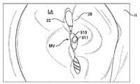
본원은 일반적으로, 자연 심장 판막의 밀봉을 돕고 통과 역류를 방지하거나 감소시키기 위한 인공 장치(prosthetic device) 및 관련 방법에 관한 것이고, 또한 그러한 인공 장치를 이식하기 위한 장치 및 관련 방법에 관한 것이다.FIELD The present disclosure generally relates to prosthetic devices and related methods for aiding the sealing of natural heart valves and to prevent or reduce passage reflux, and also to devices and related methods for implanting such artificial devices.
자연 심장 판막(즉, 대동맥 판막, 폐동맥 판막, 삼첨판, 및 이첨판)은, 심혈관계를 통한 혈액의 적절한 공급의 정방향 유동을 보장하는데 있어서 중요한 기능을 한다. 이러한 심장 판막은, 선천성 기형, 염증 프로세스, 감염 질환, 또는 질병에 의해서, 손상될 수 있고, 그에 따라 덜 효과적이 될 수 있다. 그러한 판막의 손상은 심각한 심혈관 손상 또는 사망을 초래할 수 있다. 수년간, 그러한 손상 판막을 위한 최종적인 치료는 개방 심장 수술 중의 판막의 수술적 보수 또는 교체였다. 그러나, 개방 심장 수술은 매우 침습적이고 많은 합병증을 초래할 수 있다. 그에 따라, 결함 심장 판막을 갖는 고령자 및 허약 환자는 종종 치료 받지 못하였다. 보다 최근에, 개방 심장 수술보다 훨씬 덜 침습적인 방식으로 인공 장치를 도입하고 이식하기 위한, 경혈관 기술이 개발되었다. 자연 이첨판 및 대동맥 판막에 접근하기 위해서 이용되는 하나의 특별한 경혈관 기술로서, 경격막(trans-septal) 기술이 있다. 경격막 기술은 카테터를 우측 대퇴 정맥 내로, 하대 정맥으로 위쪽으로, 그리고 우심방 내로 삽입하는 것을 포함한다. 이어서, 격막이 천공되고 카테터가 좌심방 내로 전달된다.Natural heart valves (ie, aortic valves, pulmonary valves, tricuspid valves, and dicuspid valves) play an important role in ensuring the forward flow of an adequate supply of blood through the cardiovascular system. Such heart valves may be damaged by congenital malformations, inflammatory processes, infectious diseases, or diseases, and thus may be less effective. Damage to such valves can result in severe cardiovascular damage or death. For years, the final treatment for such damaged valves has been surgical repair or replacement of the valves during open heart surgery. However, open heart surgery is very invasive and can lead to many complications. As such, elderly and fragile patients with defective heart valves were often untreated. More recently, transvascular techniques have been developed for introducing and implanting artificial devices in a much less invasive manner than open heart surgery. One particular transvascular technique that is used to access natural spinal valves and aortic valves is the trans-septal technique. Diaphragm techniques include inserting the catheter into the right femoral vein, upward into the inferior vena cava, and into the right atrium. The diaphragm is then perforated and the catheter is delivered into the left atrium.
건강한 심장은, 하부 정점까지 테이퍼링되는(taper) 전반적으로 원뿔형인 형상을 갖는다. 심장은 4개-챔버를 가지며, 좌심방, 우심방, 좌심실, 및 우심실을 포함한다. 심장의 좌측 측면 및 우측 측면은, 격막으로 일반적으로 지칭되는 벽에 의해서 분리된다. 인간 심장의 자연 이첨판은 좌심방을 좌심실에 연결한다. 이첨판은 다른 자연 심장 판막과 매우 상이한 해부조직을 갖는다. 이첨판은, 이첨판 오리피스를 둘러싸는 자연 판막 조직의 환상 부분(annular portion)인 환형 부분, 및 환형부로부터 좌심실 내로 하향 연장되는 첨부(cusp), 또는 판막첨(leaflet)의 쌍을 포함한다. 이첨판 환형부는, 장축 및 단축을 갖는, "D"-형상, 난형, 또는 달리 원을 벗어나는(out-of-round) 횡단면 형상을 형성할 수 있다. 전방 판막첨이 후방 판막첨보다 클 수 있고, 그에 따라 이들이 서로 근접될 때 판막첨의 접경되는 측면들 사이에서 전반적으로 "C"-형상인 경계를 형성한다.The healthy heart has an overall conical shape that tapers to the lower peak. The heart has a four-chamber and includes the left atrium, the right atrium, the left ventricle, and the right ventricle. The left and right sides of the heart are separated by walls, commonly referred to as septums. The natural spinal plates of the human heart connect the left atrium to the left ventricle. The tertiary valve has anatomical tissue very different from other natural heart valves. The tricuspid plate comprises an annular portion, which is an annular portion of the natural valve tissue surrounding the tricuspid orifice, and a pair of cusps, or leaflets, extending downward from the annulus into the left ventricle. The tricuspid annulus can form a “D” -shaped, ovoid, or otherwise out-of-round cross-sectional shape having a major axis and a minor axis. The anterior valve tip may be larger than the posterior valve tip, thus forming an overall “C” -shaped boundary between the bordering sides of the valve tip when they are close to each other.
적절히 동작할 때, 전방 판막첨 및 후방 판막첨은 일방향 판막으로서 함께 기능하고, 그에 따라 혈액이 좌심방으로부터 좌심실로만 유동할 수 있게 한다. 좌심방은 폐정맥으로부터 산소화 혈액(oxygenated blood)을 수용한다. ("심실 확장기" 또는 "확장기"로도 지칭되는) 좌심방의 근육이 수축되고 좌심실이 확장될 때, 좌심방 내에 수집된 산소화 혈액이 좌심실 내로 유동된다. ("심실 수축기" 또는 "수축기"로도 지칭되는) 좌심방 근육이 이완되고 좌심실 근육이 수축될 때, 좌심실 내의 증가된 혈압이 2개의 판막첨의 측면들을 함께 압박하고, 그에 의해서 일방향 이첨판을 폐쇄하며, 그에 따라 혈액은 좌심방으로 역류할 수 없고 그 대신 대동맥 판막을 통해서 좌심실의 외부로 방출된다. 2개의 판막첨이 압력하에서 이탈되는 것 그리고 이첨판 환형부를 통해서 좌심방을 향해 역으로 절첩되는 것을 방지하기 위해서, 건삭이라고 지칭되는 복수의 섬유 코드가 판막첨을 좌심실 내의 유두근에 속박시킨다.When properly operated, the anterior and posterior valve peaks function together as one-way valves, thereby allowing blood to flow only from the left atrium to the left ventricle. The left atrium receives oxygenated blood from the pulmonary vein. When the muscles of the left atrium (also referred to as "ventricular dilator" or "dilator") are contracted and the left ventricle expands, oxygenated blood collected in the left atrium flows into the left ventricle. When the left atrium muscle (also referred to as the "ventricular systolic" or "constrictor") relaxes and the left ventricular muscle contracts, the increased blood pressure in the left ventricle compresses the sides of the two valves together, thereby closing the one-way spinal valve, As a result, blood cannot flow back to the left atrium and instead is released through the aortic valve to the outside of the left ventricle. In order to prevent the release of the two valve tips under pressure and the reverse folding of the valve annulus toward the left atrium, a plurality of fiber cords, referred to as dry, bind the valve tips to the papillary muscles in the left ventricle.
이첨판 역류는, 심장 수축의 수축기 위상 중에 자연 이첨판이 적절히 폐쇄되지 않고 혈액이 좌심실로부터 좌심방 내로 유동될 때 발생된다. 이첨판 역류는 판막계 심장 질병의 가장 일반적인 형태이다. 이첨판 역류는, 판막첨 이탈, 기능 장애 유두근, 및/또는 좌심실의 확장으로부터 초래되는 이첨판 환형부의 연신과 같은, 상이한 원인들을 갖는다. 판막첨의 중앙 부분에서의 이첨판 역류는 중앙 제트 이첨판 역류로서 지칭되고, 판막첨의 하나의 접합면(즉, 판막첨이 만나는 위치) 부근의 이첨판 역류는 편심 제트 이첨판 역류로 지칭될 수 있다. 중앙 제트 역류의 경우에, 판막첨의 연부가 중간에서 만나지 않을 때 발생하고, 그에 따라, 판막은 폐쇄되지 않고 역류가 존재하게 된다.Adjunctival regurgitation occurs when blood flows from the left ventricle into the left atrium without adequate closure of the natural adjunct during the systolic phase of heart contraction. Tinplate reflux is the most common form of valve heart disease. Binary valve regurgitation has different causes, such as valve release, dysfunctional papillae, and / or stretching of the annular annulus resulting from dilation of the left ventricle. The tricuspid regurgitation in the central portion of the valve leaflets may be referred to as the central jet tricuspid regurgitation, and the tricuspid regurgitation near one junction surface (ie, the location where the valve meets) may be referred to as eccentric jet tricuspid regurgitation. In the case of central jet reflux, it occurs when the edges of the valve tips do not meet in the middle, so that the valve is not closed and there is a reflux.
환자의 이첨판 역류를 치료하기 위한 일부 종래의 기술은, 자연 이첨판 판막첨의 연부를 서로 직접적으로 수술적으로 봉합하는 것을 포함한다. 카테터 전달된 클립을 이용하여, 수술적 봉합 방법과 유사하게, 판막첨의 단부 부분들에서 판막첨의 측면들을 함께 클립체결하기 위한 시도가 있었다. 그러나, 이러한 클립은 단점을 가지는데, 이는, 판막첨이 약 2 mm 이상 중첩되는 판막첨의 중간을 클립체결하기 위해서만 이용될 수 있기 때문이다. 대안적으로, 판막첨의 더 많은 중첩이 존재할 수 있는 이첨판의 접합면들 상에서 다수의 클립을 이용하기 위한 시도가 있었다. 이러한 기술은, 더 긴 수술 시간을 초래하고, 또한 측면들에서 환자의 판막첨들을 접합하여 혈액 유동을 제한한다. 추가로, 수술적 치료 및 클립 치료 모두는 환자의 판막첨 상에서 응력을 생성하는 것으로 생각된다.Some conventional techniques for treating dendritic regurgitation in a patient include surgically suturing the edges of the natural tricuspid valve leaflets directly with one another. Using a catheter delivered clip, similar attempts have been made to clip the sides of the valve tip together at the end portions of the valve tip, similar to the surgical suture method. However, this clip has a drawback, since it can only be used to clip the middle of the valve tip where the valve tip overlaps about 2 mm or more. Alternatively, attempts have been made to use multiple clips on the joining surfaces of the backplates where there may be more overlap of the valve stems. This technique results in longer surgical time and also limits the blood flow by joining the patient's valve tips on the sides. In addition, both surgical and clip treatment are believed to produce stress on the patient's valve apex.
이러한 종래 기술에도 불구하고, 이첨판 역류를 치료하기 위한 개선된 장치 및 방법이 계속 요구되고 있다.Despite these prior arts, there is a continuing need for improved apparatus and methods for treating tricuspid regurgitation.
예시적인 이식가능한 인공 장치는 접합 요소(coaption element) 및 적어도 하나의 앵커를 갖는다. 접합 요소는 자연 심장 판막 오리피스 내에 위치설정되어 자연 판막이 역류되는 공간을 채우고 보다 효과적인 밀봉부를 형성하는 것을 돕도록 구성된다. 접합 요소는 혈액에 대해 불투과성이고, 혈액이 좌심실 또는 우심실로부터 좌심방 또는 우심방으로 각각 유동하는 것을 차단하기 위해 심실 수축기 중에 자연 판막첨이 접합 요소 주위를 폐쇄하도록 허용하는 구조를 가질 수 있다. 접합 요소는 앵커에 의해 자연 판막의 판막첨에 연결될 수 있다.Exemplary implantable prosthetic devices have a bonding element and at least one anchor. The bonding element is positioned within the natural heart valve orifice and is configured to fill the space in which the natural valve flows back and to help form a more effective seal. The junction element is impermeable to blood and may have a structure that allows the natural valve tip to close around the junction element during the ventricular systolic to block blood from flowing from the left or right ventricle to the left or right atrium, respectively. The joining element can be connected to the valve tip of the natural valve by an anchor.
특히 유사한 부분들이 유사한 참조 번호를 가지는 첨부 도면과 함께 고려할 때, 본 발명의 성질 및 장점에 관한 추가적인 이해가 이하의 설명 및 청구항에 기재되어 있다.Further understanding of the nature and advantages of the invention is set forth in the following description and claims, particularly when taken in conjunction with the accompanying drawings, in which like parts have like reference numerals.
본 개시내용의 실시예의 다양한 양태를 더 명확하게 하기 위해, 첨부 도면의 다양한 양태를 참조하여 특정 실시예에 대한 보다 특정한 설명이 이루어질 것이다. 이들 도면은 본 개시내용의 전형적인 실시예만을 도시하므로 본 개시내용의 범주를 제한하는 것으로 간주되지 않는다는 것이 이해된다. 또한, 도면은 일부 실시예에 대해 축척대로 도시될 수 있지만, 도면은 모든 실시예에 대해 반드시 축척대로 도시되지는 않는다. 본 개시내용의 실시예 및 다른 특징 및 장점이 첨부 도면의 사용을 통해 추가의 특이성 및 상세에서 기술 및 설명될 것이다.
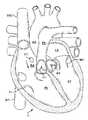
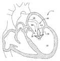
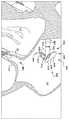
도 1은 확장기 위상에서의 인간 심장의 절결도를 도시한다.
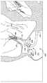
도 2는 수축기 위상에서의 인간 심장의 절결도를 도시한다.
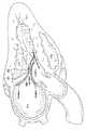
도 2a는 수축기 위상에서의 인간 심장의 다른 절결도이다.
도 2b는 수축기 위상에서의 이첨판 판막첨의 자연스러운 형상을 도시하기 위해 주석이 달린 도 2a의 절결도이다.
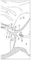
도 3은 건삭이 이첨판 및 삼첨판의 판막첨을 심실 벽에 부착하는 것으로 도시되는, 확장기 위상에서의 인간 심장의 절결도를 도시한다.
도 4는 이첨판의 심방측으로부터 볼 때 판막첨이 폐쇄된 상태의 건강한 이첨판을 도시한다.
도 5는 이첨판의 심방측으로부터 볼 때 판막첨 사이에 가시적인 간극을 갖는, 제대로 기능을 하지 않는 이첨판을 도시한다.
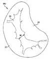
도 6은 후방 판막첨과 전방 판막첨 사이에 넓은 간극을 갖는 이첨판을 도시한다.
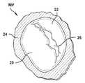
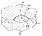
도 6a는 이첨판의 심방측으로부터 볼 때 이첨판의 간극 내의 접합 요소를 도시한다.
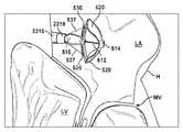
도 6b는 이첨판의 심실측으로부터 볼 때 이첨판의 간극 내의 접합 요소로 이첨판 판막첨에 부착된 판막 보수 장치를 도시한다.
도 6c는 이첨판의 심실측으로부터 도시된 이첨판의 간극 내의 접합 요소로 이첨판 판막첨에 부착된 판막 보수 장치의 사시도이다.
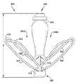
도 6d는 이첨판 보수 장치의 접합 요소의 각각의 측면을 따른 이첨판 판막첨의 경로를 도시하는 개략도이다.
도 6e는 이첨판 보수 장치의 접합 요소 주위의 이첨판 판막첨의 경로를 도시하는 상부 개략도이다.
도 7은 삼첨판의 심방측으로부터 본 삼첨판을 도시한다.
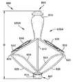
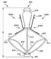
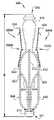
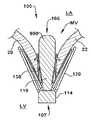
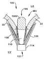
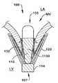
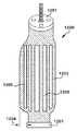
도 8 내지 도 14는 다양한 전개 단계에서의, 이식가능한 인공 장치의 예시적인 실시예를 도시한다.
도 11a는 도 11에 도시된 장치와 유사하지만, 패들이 독립적으로 제어 가능한, 이식가능한 인공 장치의 예시적인 실시예를 도시한다.
도 15 내지 도 20은 도 8 내지 도 14의 이식가능한 인공 장치가 자연 이첨판 내에 전달되고 이식되는 것을 도시한다.
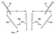
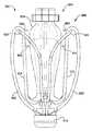
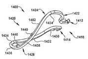
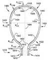
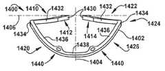
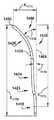
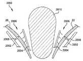
도 21은 이식가능한 인공 장치의 예시적인 실시예를 도시한다.
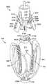
도 22는 이식가능한 인공 장치의 예시적인 실시예를 도시한다.
도 23 내지 도 25는 이식가능한 인공 장치의 예시적인 실시예를 도시한다.
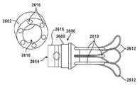
도 26 및 도 27은 이식가능한 인공 장치에서 사용하기 위한 바브형 클래스프의 예시적인 실시예를 도시한다.
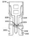
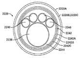
도 28 내지 도 32는 이식가능한 인공 장치의 예시적인 실시예를 도시한다.
도 32a 및 도 32b는 각각 밀봉되고 이격된 위치에서의 도 28 내지 도 32의 이식가능한 인공 장치의 캡 및 접합 요소 삽입체의 사시도이다.
도 33은 이식가능한 인공 장치에서 사용하기 위한 바브형 클래스프를 도시한다.
도 34는 바브형 클래스프에 의해 파지된 이첨판 조직의 일부를 도시한다.
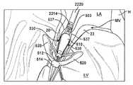
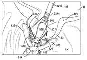
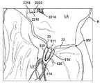
도 35 내지 도 46은 자연 이첨판 내에 전달되고 이식되는 이식가능한 인공 장치의 예시적인 실시예를 도시한다.
도 47은 폐쇄 위치에서 바브형 클래스프가 없는 예시적인 이식가능한 인공 장치의 측면도를 도시한다.
도 48은 폐쇄 위치에서 바브형 클래스프를 갖는 예시적인 이식가능한 인공 장치의 측면도를 도시한다.
도 49는 부분 개방 위치에서 바브형 클래스프가 없는 예시적인 이식가능한 인공 장치의 측면도를 도시한다.
도 50은 개방 위치에서 바브형 클래스프를 갖는 부분 개방 위치에서의 예시적인 이식가능한 인공 장치의 측면도를 도시한다.
도 51은 폐쇄 위치에서 바브형 클래스프를 갖는 부분 개방 위치에서의 예시적인 이식가능한 인공 장치의 측면도를 도시한다.
도 52는 반-개방 위치에서 바브형 클래스프가 없는 예시적인 이식가능한 인공 장치의 측면도를 도시한다.
도 53은 폐쇄 위치에서 바브형 클래스프를 갖는 절반-개방 위치에서의 예시적인 이식가능한 인공 장치의 측면도를 도시한다.
도 54는 개방 위치에서 바브형 클래스프를 갖는 반-개방 위치에서의 예시적인 이식가능한 인공 장치의 측면도를 도시한다.
도 55는 3/4-개방 위치에서 바브형 클래스프가 없는 예시적인 이식가능한 인공 장치의 측면도를 도시한다.
도 56은 폐쇄 위치에서 바브형 클래스프를 갖는 3/4-개방 위치에서의 예시적인 이식가능한 인공 장치의 측면도를 도시한다.
도 57은 개방 위치에서 바브형 클래스프를 갖는 3/4-개방 위치에서의 예시적인 이식가능한 인공 장치의 측면도를 도시한다.
도 58은 전체 베일아웃(bailout) 위치 부근에서 바브형 클래스프가 없는 예시적인 이식가능한 인공 장치의 측면도를 도시한다.
도 59는 전체 베일아웃 위치에서 바브형 클래스프가 없는 예시적인 이식가능한 인공 장치의 측면도를 도시한다.
도 60은 폐쇄 위치에서 바브형 클래스프를 갖는 전체 베일아웃 위치에서의 예시적인 이식가능한 인공 장치의 측면도를 도시한다.
도 61은 개방 위치에서 바브형 클래스프를 갖는 전체 베일아웃 위치에서의 예시적인 이식가능한 인공 장치의 측면도를 도시한다.
도 62a 및 도 62b는 이식가능한 인공 장치의 예시적인 실시예의 패들의 이동을 도시한다.
도 63a 내지 도 63c는 이식가능한 인공 장치의 예시적인 실시예의 패들의 이동을 도시한다.
도 64a 내지 도 64c는 이식가능한 인공 장치의 예시적인 실시예의 패들의 이동을 도시한다.
도 65는 폐쇄 위치에서의 예시적인 이식가능한 인공 장치의 사시도이다.
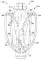
도 66은 도 65의 이식가능한 인공 장치의 사시도를 도시한다.
도 67은 도 65의 이식가능한 인공 장치의 정면도를 도시한다.
도 68은 추가의 구성요소를 갖는 도 65의 이식가능한 인공 장치의 정면도를 도시한다.
도 69는 도 65의 이식가능한 인공 장치의 측면도를 도시한다.
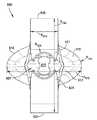
도 70은 도 65의 이식가능한 인공 장치의 평면도를 도시한다.
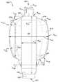
도 71은 칼라 구성요소를 갖는 도 65의 이식가능한 인공 장치의 평면도이다.
도 72는 도 65의 이식가능한 인공 장치의 저면도를 도시한다.
도 73은 캡 구성요소를 갖는 도 65의 이식가능한 인공 장치의 저면도를 도시한다.
도 74는 단면 평면(75)에 의해 구획된 도 65의 이식가능한 인공 장치의 단면 사시도를 도시한다.
도 75는 도 74에 도시된 예시적인 인공 장치의 상부 단면도를 도시한다.
도 76은 단면 평면(77)에 의해 구획된 도 65의 이식가능한 인공 장치의 단면 사시도를 도시한다.
도 77은 도 76에 도시된 예시적인 인공 장치의 상부 단면도를 도시한다.
도 78은 단면 평면(77)에 의해 구획된 도 65의 이식가능한 인공 장치의 단면 사시도를 도시한다.
도 79는 도 78에 도시된 예시적인 인공 장치의 상부 단면도를 도시한다.
도 80은 단면 평면(81)에 의해 구획된 도 65의 이식가능한 인공 장치의 단면 사시도를 도시한다.
도 81은 도 80에 도시된 예시적인 인공 장치의 상부 단면도를 도시한다.
도 82는 단면 평면(83)에 의해 구획된 도 65의 이식가능한 인공 장치의 단면 사시도를 도시한다.
도 83은 도 82에 도시된 예시적인 인공 장치의 상부 단면도를 도시한다.
도 84는 일체형 바브를 갖는 이식가능한 인공 장치의 예시적인 실시예를 도시한다.
도 85는 일체형 바브를 갖는 이식가능한 인공 장치의 예시적인 실시예를 도시한다.
도 86은 일체형 바브를 갖는 이식가능한 인공 장치의 예시적인 실시예를 도시한다.
도 87은 일체형 바브를 갖는 이식가능한 인공 장치의 예시적인 실시예를 도시한다.
도 88은 일체형 바브를 갖는 이식가능한 인공 장치의 예시적인 실시예를 도시한다.
도 89는 도 65에 도시된 이식가능한 인공 장치의 접합 부분 및 패들 부분의 사시도를 도시한다.
도 90은 도 65에 도시된 이식가능한 인공 장치의 접합 부분 및 패들 부분의 사시도를 도시한다.
도 91은 도 65에 도시된 이식가능한 인공 장치의 접합 부분 및 패들 부분의 정면도를 도시한다.
도 92는 도 65에 도시된 이식가능한 인공 장치의 접합 부분 및 패들 부분의 측면도를 도시한다.
도 93은 도 65에 도시된 이식가능한 인공 장치의 접합 부분 및 패들 부분의 평면도를 도시한다.
도 94는 도 65에 도시된 이식가능한 인공 장치의 일부 및 접합 부분의 저면도를 도시한다.
도 95는 평면(96)을 가로질러 취한 단면을 갖는, 도 65에 도시된 이식가능한 인공 장치의 접합 부분 및 패들 부분의 단면 사시도를 도시한다.
도 96은 도 95의 접합 부분 및 패들 부분의 단면도를 도시한다.
도 97은 평면(98)을 가로질러 취한 단면을 갖는, 도 65에 도시된 이식가능한 인공 장치의 접합 부분 및 패들 부분의 단면 사시도를 도시한다.
도 98은 도 97의 접합 부분 및 패들 부분의 단면도를 도시한다.
도 99는 평면(100)을 가로질러 취한 단면을 갖는, 도 65에 도시된 이식가능한 인공 장치의 접합 부분 및 패들 부분의 단면 사시도를 도시한다.
도 100은 도 99의 접합 부분 및 패들 부분의 단면도를 도시한다.
도 101은 평면(102)을 가로질러 취한 단면을 갖는, 도 65에 도시된 이식가능한 인공 장치의 접합 부분 및 패들 부분의 단면 사시도를 도시한다.
도 102는 도 101의 접합 부분 및 패들 부분의 단면도를 도시한다.
도 103은 이식가능한 인공 장치의 예시적인 실시예를 도시한다.
도 104는 이식가능한 인공 장치의 예시적인 실시예를 도시한다.
도 105는 이식가능한 인공 장치의 예시적인 실시예를 도시한다.
도 106은 확장되지 않은 상태의 확장 가능한 접합 요소의 예시적인 실시예의 측면도를 도시한다.
도 106a는 확장되지 않은 상태의 확장 가능한 접합 요소의 예시적인 실시예의 측면도를 도시한다.
도 106b는 확장되지 않은 상태의 확장 가능한 접합 요소의 예시적인 실시예의 측면도를 도시한다.
도 106c는 확장되지 않은 상태의 확장 가능한 접합 요소의 예시적인 실시예의 측면도를 도시한다.
도 106d는 확장되지 않은 상태의 확장 가능한 접합 요소의 예시적인 실시예의 측면도를 도시한다.
도 106e는 확장되지 않은 상태의 확장 가능한 접합 요소의 예시적인 실시예의 측면도를 도시한다.
도 106f는 확장 가능한 접합 요소의 예시적인 실시예를 도시한다.
도 106g는 확장 가능한 접합 요소의 예시적인 실시예를 도시한다.
도 106h는 확장 가능한 접합 요소의 예시적인 실시예를 도시한다.
도 106i는 확장 가능한 접합 요소의 예시적인 실시예를 도시한다.
도 107은 도 106의 확장 가능한 접합 요소의 단부도를 도시한다.
도 108은 확장된 상태의 도 106의 확장 가능한 접합 요소를 도시한다.
도 108a는 확장된 상태의 도 106a의 확장 가능한 접합 요소를 도시한다.
도 108b는 확장된 상태의 도 106b의 확장 가능한 접합 요소를 도시한다.
도 108c는 확장된 상태의 도 106c의 확장 가능한 접합 요소를 도시한다.
도 108d는 확장된 상태의 도 106d의 확장 가능한 접합 요소를 도시한다.
도 108e는 확장된 상태의 도 106e의 확장 가능한 접합 요소를 도시한다.
도 109는 도 108의 접합 요소의 단부도이다.
도 108은 압축된 상태의 도 106의 예시적인 인공 장치를 위한 접합 요소의 측면도를 도시한다.
도 109는 도 108의 접합 요소의 단부도이다.
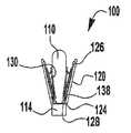
도 110은 이식가능한 인공 장치의 예시적인 실시예의 측면도를 도시한다.
도 111은 라인(111)을 따라 취한, 도 110의 예시적인 인공 장치의 접합 요소의 단부도이다.
도 112 내지 도 114는 도 65의 이식가능한 인공 장치를 위한 패들 프레임의 예시적인 실시예의 사시도를 도시한다.
도 115는 도 112 내지 도 114의 패들 프레임의 정면도를 도시한다.
도 116은 도 112 내지 도 114의 패들 프레임의 평면도를 도시한다.
도 117은 도 112 내지 도 114의 패들 프레임의 측면도를 도시한다.
도 118은 도 112 내지 도 114의 패들 프레임의 저면도를 도시한다.
도 119는 도 112 내지 도 114의 패들 프레임의 정면도를 도시한다.
도 120은 전달 장치 내부의 압축된 상태의 도 112 내지 도 114의 패들 프레임의 정면도를 도시한다.
도 121은 폐쇄 상태의 이식가능한 인공 장치의 예시적인 실시예의 측면도를 도시한다.
도 122는 도 121의 예시적인 인공 장치의 패들 프레임의 정면도를 도시한다.
도 123은 폐쇄 상태의 도 121의 이식가능한 인공 장치의 측면도를 도시한다.
도 124는 도 123의 개방 인공 장치의 패들 프레임의 정면도를 도시한다.
도 125는 폐쇄 상태의 이식가능한 인공 장치의 예시적인 실시예의 측면도를 도시한다.
도 126은 도 125의 예시적인 인공 장치의 패들 프레임의 정면도를 도시한다.
도 127은 폐쇄 상태의 도 125의 이식가능한 인공 장치의 측면도를 도시한다.
도 128은 도 127의 개방 인공 장치의 패들 프레임의 정면도를 도시한다.
도 129는 이식가능한 인공 장치의 예시적인 실시예를 도시한다.
도 130 및 도 131은 이식가능한 인공 장치의 예시적인 실시예를 도시한다.
도 132는 이식가능한 인공 장치의 예시적인 실시예를 도시한다.
도 133 및 도 134는 이식가능한 인공 장치의 예시적인 실시예를 도시한다.
도 135 및 도 136은 이식가능한 인공 장치의 예시적인 실시예를 도시한다.
도 137은 이식가능한 인공 장치의 예시적인 실시예를 도시한다.
도 138 내지 도 143은 이식가능한 인공 장치의 예시적인 실시예의 사용을 도시한다.
도 144는 전달 장치 및 예시적인 인공 장치를 포함하는 전달 조립체의 예시적인 실시예를 도시한다.
도 145는 전달 장치에 해제 가능하게 커플링된 이식가능한 인공 장치의 예시적인 실시예의 사시도를 도시한다.
도 146은 이식가능한 인공 장치가 전달 장치로부터 해제된, 도 145의 실시예를 도시한다.
도 147은 도 145의 커플러의 단면도를 도시한다.
도 148은 인공 장치가 부분 단면으로 도시되고 전달 장치의 일부 구성요소가 개략적으로 도시된, 도 144의 전달 조립체의 사시도를 도시한다.
도 149는 도 144의 전달 장치의 샤프트의 평면도를 도시한다.
도 150은 도 144의 전달 장치의 근위 단부 부분의 측면도를 도시한다.
도 151은 도 150에 도시된 라인(150-150)을 따라 취한, 도 144의 전달 장치의 근위 단부 부분의 단면도를 도시한다.
도 152는 도 144의 전달 장치의 근위 단부 부분의 분해도를 도시한다.
도 153 내지 도 160은 부분적으로 도시된, 심장의 자연 이첨판을 보수하기 위해 사용되는 예시적인 절차를 도시한다.
도 161은 도 144의 전달 장치를 위한 핸들의 예시적인 실시예를 도시한다.
도 162는 도 161의 핸들의 분해도이다.
도 163은 커플러가 근위 칼라에 해제 가능하게 커플링되는 것을 도시하는, 도 144의 전달 조립체를 위한 커플러 및 근위 칼라의 예시적인 실시예를 도시한다.
도 164는 커플러가 근위 칼라로부터 해제되는 것을 도시하는, 도 163의 커플러 및 근위 칼라의 사시도이다.
도 165는 캡이 해제 와이어에 의해 작동 샤프트에 해제 가능하게 커플링되는 것을 도시하는, 도 144의 전달 조립체를 위한 캡, 작동 샤프트, 및 해제 와이어의 다른 예시적인 실시예를 도시한다.
도 166은 캡이 작동 샤프트 및 해제 와이어로부터 해제되는 것을 도시하는, 도 163의 캡, 작동 샤프트, 및 해제 와이어의 사시도를 도시한다.
도 167은 도 144의 전달 조립체의 커플러, 근위 칼라, 캡, 및 작동 샤프트의 다른 예시적인 실시예를 도시한다.
도 168은 도 167의 커플러 및 근위 칼라의 사시도를 도시한다.
도 169는 도 144의 전달 장치의 클래스프 제어 부재의 예시적인 실시예를 도시한다.
도 170은 도 169에 도시된 관점(170)으로부터 취한, 도 169의 클래스프 제어 부재의 상세도를 도시한다.
도 171은 도 169의 클래스프 제어 부재를 위한 안내 레일의 예시적인 실시예를 도시한다.
도 172는 도 144의 전달 장치의 샤프트의 예시적인 실시예를 도시한다.
도 173 내지 도 176은 인공 장치를 해제 및 재포획하기 위한 이식가능한 인공 장치 및 전달 장치의 예시적인 실시예를 도시한다.
도 174a 및 도 175a는 인공 장치를 해제 및 재포획하기 위한 이식가능한 인공 장치 및 전달 장치의 예시적인 실시예를 도시한다.
도 177 및 도 178은 예시적인 이식가능한 인공 장치를 위한 커플러의 예시적인 실시예를 도시한다.
도 179 내지 도 181은 예시적인 이식가능한 인공 장치를 위한 커플러의 예시적인 실시예를 도시한다.
도 182 및 도 183은 예시적인 이식가능한 인공 장치를 위한 커플러의 예시적인 실시예를 도시한다.
도 184 및 도 185는 예시적인 이식가능한 인공 장치를 위한 커플러의 예시적인 실시예를 도시한다.
도 186은 예시적인 인공 장치를 위한 작동 샤프트의 예시적인 실시예를 도시한다.
도 187은 예시적인 인공 장치에 대한 작동 기구를 도시한다.
도 188은 예시적인 인공 장치에 대한 작동 기구를 도시한다.
도 188a는 예시적인 인공 장치에 대한 작동 기구를 도시한다.
도 189는 예시적인 인공 장치에 대한 작동 기구를 도시한다.
도 190은 예시적인 인공 장치에 대한 작동 기구를 도시한다.
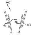
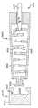
도 191은 패들 프레임을 제조하는 데 사용되는 블랭크의 사시도이다.
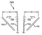
도 192는 패들 프레임을 제조하기 위해 굴곡된 도 191의 블랭크의 사시도이다.
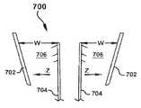
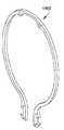
도 193은 판막 보수 장치의 캡에 부착된 형상 설정 패들 프레임의 사시도이다.
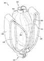
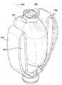
도 194는 폐쇄 위치에서 내부 패들 및 외부 패들에 굴곡되고 부착된 도 193의 패들 프레임의 사시도이다.To more clearly illustrate various aspects of embodiments of the present disclosure, a more specific description of specific embodiments will be made with reference to the various aspects of the accompanying drawings. It is understood that these drawings show only typical embodiments of the present disclosure and are not to be considered limiting of the scope of the present disclosure. In addition, while the drawings may be shown to scale for some embodiments, the drawings are not necessarily to scale for all embodiments. Embodiments and other features and advantages of the present disclosure will be described and described in further specificity and detail through use of the accompanying drawings.
1 shows the cutout of the human heart in the diastolic phase.
2 shows the cutout of the human heart in the systolic phase.
2A is another cutaway view of the human heart in the systolic phase.
FIG. 2B is a cutaway view of FIG. 2A annotated to show the natural shape of the tricuspid valve annulus in the systolic phase.
FIG. 3 shows a cutaway view of the human heart in the diastolic phase, in which the abdomen is attached to the ventricular wall of the tricuspid and tricuspid valves.
4 shows a healthy spinal valve in a closed state as seen from the atrial side of the spinal valve.
FIG. 5 shows a dysfunction plate not functioning properly, with visible gaps between the apexes when viewed from the atrial side of the adjunct plate.
FIG. 6 shows a dipplate with a wide gap between the posterior and anterior valve peaks. FIG.
FIG. 6A shows the joining elements in the gap of the ear plate as viewed from the atrial side of the ear plate.
FIG. 6B shows the valve repair apparatus attached to the valve leaflet with a joining element in the gap of the valve, as seen from the ventricular side of the plate.
FIG. 6C is a perspective view of the valve repair apparatus attached to the valve leaflet with the joining elements in the gap of the platelet shown from the ventricular side of the platelet. FIG.
FIG. 6D is a schematic diagram illustrating the path of the valve leaflet along each side of the bonding element of the platelet repair device. FIG.
FIG. 6E is a top schematic diagram illustrating the path of the tricuspid valve annulus around the bonding element of the tricuspid repair device. FIG.
7 shows the tricuspid valve seen from the atrial side of the tricuspid valve.
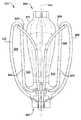
8-14 illustrate exemplary embodiments of implantable prosthetic devices at various stages of deployment.
FIG. 11A illustrates an example embodiment of an implantable artificial device, similar to the device shown in FIG. 11, but with paddles independently controlled.
15-20 illustrate the implantable artificial device of FIGS. 8-14 being delivered and implanted in a natural spinal plate.
21 illustrates an exemplary embodiment of an implantable artificial device.
22 illustrates an example embodiment of an implantable artificial device.
23-25 illustrate exemplary embodiments of implantable artificial devices.
26 and 27 illustrate exemplary embodiments of barbed clasps for use in implantable prosthetic devices.
28-32 illustrate example embodiments of implantable artificial devices.
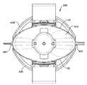
32A and 32B are perspective views of the cap and joint element insert of the implantable prosthetic device of FIGS. 28-32, respectively, in a sealed and spaced position.
33 illustrates a barbed clasp for use in an implantable artificial device.
34 shows a portion of the dendritic tissue gripped by barb clasps.
35-46 illustrate exemplary embodiments of implantable prosthetic devices that are delivered and implanted in natural platelets.
47 shows a side view of an exemplary implantable prosthetic device without a barbed clasp in the closed position.
48 shows a side view of an exemplary implantable prosthetic device having a barbed clasp in the closed position.
FIG. 49 shows a side view of an exemplary implantable prosthetic device without a barbed clasp in a partially open position. FIG.
50 shows a side view of an exemplary implantable prosthetic device in a partially open position with a barbed clasp in the open position.
FIG. 51 shows a side view of an exemplary implantable prosthetic device in a partially open position with a barbed clasp in the closed position.
FIG. 52 shows a side view of an exemplary implantable prosthetic device without a barbed clasp in a semi-open position.
FIG. 53 shows a side view of an exemplary implantable prosthetic device in a half-open position with a barbed clasp in the closed position.
54 shows a side view of an exemplary implantable prosthetic device in a semi-open position with a barbed clasp in the open position.
55 shows a side view of an exemplary implantable prosthetic device without barbed clasp in the 3 / 4-open position.
56 shows a side view of an exemplary implantable prosthetic device in the 3 / 4-open position with a barbed clasp in the closed position.
FIG. 57 shows a side view of an exemplary implantable prosthetic device in the 3 / 4-open position with a barbed clasp in the open position.
FIG. 58 shows a side view of an exemplary implantable prosthetic device without a barbed clasp near the entire bailout position.
FIG. 59 shows a side view of an exemplary implantable prosthetic device without barbed clasp in full bailout position.
FIG. 60 shows a side view of an exemplary implantable prosthetic device in the full bailout position with a barbed clasp in the closed position.
FIG. 61 shows a side view of an exemplary implantable prosthetic device in the full bailout position with a barbed clasp in the open position.
62A and 62B show the paddle movement of an exemplary embodiment of an implantable artificial device.
63A-63C illustrate the movement of a paddle of an exemplary embodiment of an implantable artificial device.
64A-64C illustrate the movement of a paddle of an exemplary embodiment of an implantable artificial device.
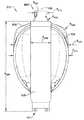
65 is a perspective view of an exemplary implantable artificial device in a closed position.
FIG. 66 shows a perspective view of the implantable artificial device of FIG. 65.
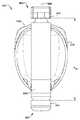
FIG. 67 shows a front view of the implantable artificial device of FIG. 65.
FIG. 68 shows a front view of the implantable artificial device of FIG. 65 with additional components.
FIG. 69 shows a side view of the implantable artificial device of FIG. 65.
FIG. 70 illustrates a top view of the implantable artificial device of FIG. 65.
71 is a top view of the implantable artificial device of FIG. 65 with a collar component.
FIG. 72 illustrates a bottom view of the implantable artificial device of FIG. 65.
73 illustrates a bottom view of the implantable artificial device of FIG. 65 with the cap component.
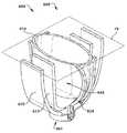
FIG. 74 illustrates a cross-sectional perspective view of the implantable artificial device of FIG. 65 partitioned by
FIG. 75 illustrates a cross-sectional top view of the example artificial device shown in FIG. 74.
FIG. 76 shows a cross-sectional perspective view of the implantable artificial device of FIG. 65 partitioned by cross section plane 77.
FIG. 77 illustrates a top cross-sectional view of the example artificial device shown in FIG. 76.
FIG. 78 shows a cross-sectional perspective view of the implantable artificial device of FIG. 65 partitioned by cross section plane 77.
FIG. 79 illustrates a top sectional view of the example artificial device shown in FIG. 78.
FIG. 80 shows a cross-sectional perspective view of the implantable artificial device of FIG. 65 partitioned by
FIG. 81 illustrates a top cross-sectional view of the example artificial device shown in FIG. 80.
FIG. 82 shows a cross-sectional perspective view of the implantable artificial device of FIG. 65 partitioned by
FIG. 83 shows a top sectional view of the example artificial device shown in FIG. 82.
84 illustrates an example embodiment of an implantable artificial device having an integral barb.
85 illustrates an example embodiment of an implantable artificial device having an integral barb.
86 illustrates an example embodiment of an implantable artificial device having an integral barb.
87 illustrates an example embodiment of an implantable artificial device having an integral barb.
88 illustrates an example embodiment of an implantable artificial device having an integral barb.
FIG. 89 illustrates a perspective view of the abutment portion and paddle portion of the implantable artificial device shown in FIG. 65.
FIG. 90 illustrates a perspective view of the abutment portion and paddle portion of the implantable artificial device shown in FIG. 65.
FIG. 91 shows a front view of the abutment portion and paddle portion of the implantable artificial device shown in FIG. 65.
FIG. 92 illustrates a side view of the abutment portion and paddle portion of the implantable artificial device shown in FIG. 65.
FIG. 93 shows a top view of the abutment portion and paddle portion of the implantable artificial device shown in FIG. 65.
FIG. 94 shows a bottom view of a portion and abutment portion of the implantable artificial device shown in FIG. 65.
FIG. 95 illustrates a cross-sectional perspective view of the abutment portion and paddle portion of the implantable artificial device shown in FIG. 65, with a cross section taken across
FIG. 96 illustrates a cross-sectional view of the bond portion and paddle portion of FIG. 95.
FIG. 97 shows a cross-sectional perspective view of the abutment and paddle portions of the implantable artificial device shown in FIG. 65, with a cross section taken across
FIG. 98 illustrates a cross-sectional view of the bond portion and paddle portion of FIG. 97.
FIG. 99 shows a cross-sectional perspective view of the abutment portion and paddle portion of the implantable artificial device shown in FIG. 65, with a cross section taken across
100 illustrates a cross-sectional view of the bond portion and paddle portion of FIG. 99.
FIG. 101 shows a cross-sectional perspective view of the abutment portion and paddle portion of the implantable artificial device shown in FIG. 65, with a cross section taken across
FIG. 102 illustrates a cross-sectional view of the bond portion and paddle portion of FIG. 101.
103 illustrates an example embodiment of an implantable artificial device.
104 illustrates an example embodiment of an implantable artificial device.
105 illustrates an example embodiment of an implantable artificial device.
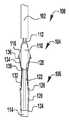
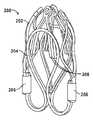
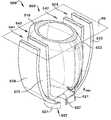
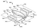
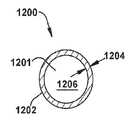
106 illustrates a side view of an example embodiment of an expandable bonding element in an unexpanded state.
106A shows a side view of an example embodiment of an expandable bonding element in an unexpanded state.
106B shows a side view of an example embodiment of an expandable bonding element in an unexpanded state.
106C shows a side view of an example embodiment of an expandable bonding element in an unexpanded state.
106D shows a side view of an example embodiment of an expandable bonding element in an unexpanded state.
106E shows a side view of an example embodiment of an expandable bonding element in an unexpanded state.
106F illustrates an example embodiment of an expandable bonding element.
106G illustrates an example embodiment of an expandable bonding element.
106H illustrates an example embodiment of an expandable bonding element.
106i illustrates an example embodiment of an expandable bonding element.
FIG. 107 shows an end view of the expandable bonding element of FIG. 106.
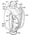
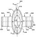
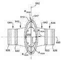
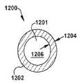
FIG. 108 illustrates the expandable bonding element of FIG. 106 in an expanded state.
108A illustrates the expandable bonding element of FIG. 106A in an expanded state.
108B illustrates the expandable bonding element of FIG. 106B in an expanded state.
108C illustrates the expandable bonding element of FIG. 106C in an expanded state.
108D illustrates the expandable bonding element of FIG. 106D in the expanded state.
108E illustrates the expandable bonding element of FIG. 106E in an expanded state.
FIG. 109 is an end view of the bonding element of FIG. 108.
FIG. 108 shows a side view of the bonding element for the example artificial device of FIG. 106 in a compressed state.
FIG. 109 is an end view of the bonding element of FIG. 108.
110 shows a side view of an example embodiment of an implantable artificial device.
FIG. 111 is an end view of the bonding element of the example artificial device of FIG. 110, taken along
112-114 show perspective views of an exemplary embodiment of a paddle frame for the implantable artificial device of FIG. 65.
FIG. 115 shows a front view of the paddle frame of FIGS. 112-114.
FIG. 116 shows a top view of the paddle frame of FIGS. 112-114.
FIG. 117 shows a side view of the paddle frame of FIGS. 112-114.
FIG. 118 shows a bottom view of the paddle frame of FIGS. 112-114.
FIG. 119 shows a front view of the paddle frame of FIGS. 112-114.
FIG. 120 shows a front view of the paddle frame of FIGS. 112-114 in a compressed state inside the delivery device.
121 illustrates a side view of an example embodiment of an implantable artificial device in a closed state.
FIG. 122 shows a front view of the paddle frame of the example artificial device of FIG. 121.
FIG. 123 shows a side view of the implantable artificial device of FIG. 121 in a closed state.
FIG. 124 shows a front view of the paddle frame of the open artificial device of FIG. 123.
125 illustrates a side view of an example embodiment of an implantable artificial device in a closed state.
FIG. 126 shows a front view of the paddle frame of the example artificial device of FIG. 125.
127 shows a side view of the implantable artificial device of FIG. 125 in a closed state.
FIG. 128 shows a front view of the paddle frame of the open artificial device of FIG. 127.
129 illustrates an example embodiment of an implantable artificial device.
130 and 131 illustrate exemplary embodiments of an implantable artificial device.
132 illustrates an example embodiment of an implantable artificial device.
133 and 134 illustrate exemplary embodiments of implantable artificial devices.
135 and 136 illustrate example embodiments of implantable artificial devices.
137 illustrates an example embodiment of an implantable artificial device.
138 to 143 illustrate the use of an exemplary embodiment of an implantable artificial device.
144 illustrates an example embodiment of a delivery assembly that includes a delivery device and an example artificial device.
145 shows a perspective view of an exemplary embodiment of an implantable artificial device releasably coupled to a delivery device.
146 illustrates the embodiment of FIG. 145 with the implantable artificial device released from the delivery device.
147 shows a cross-sectional view of the coupler of FIG. 145.
FIG. 148 shows a perspective view of the delivery assembly of FIG. 144 with the artificial device shown in partial cross section and with some components of the delivery device schematically shown.
149 shows a plan view of the shaft of the delivery device of FIG. 144.
FIG. 150 shows a side view of the proximal end portion of the delivery device of FIG. 144.
FIG. 151 shows a cross-sectional view of the proximal end portion of the delivery device of FIG. 144, taken along line 150-150 shown in FIG. 150.
152 shows an exploded view of the proximal end portion of the delivery device of FIG. 144.
153 through 160 illustrate example procedures used to repair the natural spinal plates of the heart, partially shown.
161 shows an exemplary embodiment of a handle for the delivery device of FIG. 144.
FIG. 162 is an exploded view of the handle of FIG. 161;
FIG. 163 shows an exemplary embodiment of the coupler and proximal collar for the delivery assembly of FIG. 144, showing the coupler releasably coupled to the proximal collar.
164 is a perspective view of the coupler and proximal collar of FIG. 163 showing the coupler released from the proximal collar.
FIG. 165 illustrates another exemplary embodiment of the cap, actuation shaft, and release wire for the delivery assembly of FIG. 144, showing that the cap is releasably coupled to the actuation shaft by a release wire.
FIG. 166 shows a perspective view of the cap, actuation shaft, and release wire of FIG. 163 showing that the cap is released from the actuation shaft and the release wire.
167 illustrates another exemplary embodiment of a coupler, proximal collar, cap, and actuating shaft of the delivery assembly of FIG. 144.
168 illustrates a perspective view of the coupler and proximal collar of FIG. 167.
FIG. 169 illustrates an exemplary embodiment of the clasp control member of the delivery device of FIG. 144.
FIG. 170 shows a detailed view of the clasp control member of FIG. 169, taken from the
FIG. 171 shows an exemplary embodiment of a guide rail for the clasp control member of FIG. 169.
172 shows an exemplary embodiment of the shaft of the delivery device of FIG. 144.
173 through 176 illustrate example embodiments of implantable artificial devices and delivery devices for releasing and recapturing an artificial device.
174A and 175A illustrate exemplary embodiments of implantable artificial devices and delivery devices for releasing and recapturing an artificial device.
177 and 178 show example embodiments of couplers for an example implantable artificial device.
179 through 181 show example embodiments of couplers for an example implantable prosthetic device.
182 and 183 show an example embodiment of a coupler for an example implantable artificial device.
184 and 185 show example embodiments of couplers for an example implantable prosthetic device.
186 shows an example embodiment of a working shaft for an example artificial device.
187 illustrates an actuation mechanism for an exemplary artificial device.
188 illustrates an actuation mechanism for an exemplary artificial device.
188A illustrates an actuation mechanism for an exemplary artificial device.
189 illustrates an actuation mechanism for an exemplary artificial device.
190 illustrates an actuation mechanism for an example artificial device.
191 is a perspective view of a blank used to make a paddle frame.
FIG. 192 is a perspective view of the blank of FIG. 191 bent to manufacture a paddle frame.
193 is a perspective view of a shaping paddle frame attached to the cap of the valve repair device.
194 is a perspective view of the paddle frame of FIG. 193 bent and attached to the inner paddle and the outer paddle in a closed position.
이하의 설명은 본 개시내용의 특정 실시예들을 도시하는, 첨부 도면을 참조한다. 상이한 구조 및 동작을 갖는 다른 실시예는 본 개시내용의 범주를 벗어나지 않는다.The following description refers to the accompanying drawings, which illustrate certain embodiments of the present disclosure. Other embodiments having different structures and operations do not depart from the scope of the present disclosure.
본 개시내용의 예시적인 실시예는 결함 심장 판막을 보수하기 위한 장치 및 방법에 관한 것이다. 전달을 위한 자연 판막 보수 장치 및 시스템의 다양한 실시예가 본 명세서에 개시되고, 이들 옵션의 임의의 조합이 구체적으로 배제되지 않으면 이루어질 수 있다는 점에 유의하여야 한다. 즉, 개시된 장치 및 시스템의 개별 구성요소는 상호 배타적이지 않거나 또는 달리 물리적으로 불가능하지 않으면 조합될 수 있다.Exemplary embodiments of the present disclosure relate to apparatus and methods for repairing a defective heart valve. It should be noted that various embodiments of natural valve repair devices and systems for delivery are disclosed herein and that any combination of these options may be made unless specifically excluded. In other words, the individual components of the disclosed apparatus and system may be combined unless they are mutually exclusive or otherwise physically impossible.
본원에서 설명되는 바와 같이, 하나 이상의 구성요소가 연결, 결합, 장착, 커플, 부착, 또는 다른 방식으로 상호 연결되는 것으로 설명될 때, 그러한 상호 연결은 구성요소 사이에서 직접적일 수 있거나, 예컨대 하나 이상의 중간 구성요소의 사용을 통해 간접적일 수 있다. 또한, 본원에서 설명되는 바와 같이, "부재", "구성요소" 또는" 부분"에 대한 언급은 단일 구조 부재, 구성요소, 또는 요소로 제한되지 않을 것이지만, 구성요소, 부재 또는 요소의 조립체를 포함할 수 있다. 또한, 본원에서 설명되는 바와 같이, 용어 "실질적으로" 및" 약"은 주어진 값 또는 상태(바람직하게는 10% 이내, 보다 바람직하게는 1% 이내, 가장 바람직하게는 0.1% 이내)에 적어도 근접하는(및 포함하는) 것으로 정의된다.As described herein, when one or more components are described as being connected, coupled, mounted, coupled, attached, or otherwise interconnected, such interconnections may be direct between the components, or may be, for example, one or more components. It may be indirect through the use of intermediate components. Also, as described herein, reference to "member", "component" or "part" will not be limited to a single structural member, component, or element, but includes an assembly of components, members, or elements. can do. In addition, as described herein, the terms “substantially” and “about” are at least close to a given value or condition (preferably within 10%, more preferably within 1%, most preferably within 0.1%). Is defined to be (and include).
도 1 및 도 2는 각각 인간 심장(H)의 확장기 및 수축기 위상에서의 절결도이다. 우심실(RV) 및 좌심실(LV)은 우심방(RA) 및 좌심방(LA)으로부터 각각, 삼첨판(TV) 및 이첨판(MV), 즉 방실 판막에 의해 분리된다. 추가로, 대동맥 판막(AV)은 상행 대동맥(AA)으로부터 좌심실(LV)을 분리하고, 폐동맥 판막(PV)은 폐동맥(PA)으로부터 우심실을 분리한다. 이러한 판막의 각각은, 일방향 유체-폐색 표면을 형성하기 위해서 유동스트림 내에서 하나로 합치는 또는 "접합"되는 각각의 오리피스를 가로질러 내향으로 연장되는 가요성 판막첨(예컨대, 도 4 및 도 5에 도시된 판막첨(20, 22))을 갖는다. 본원의 자연 판막 보수 시스템은 주로 이첨판(MV)에 대해 설명된다. 따라서, 좌심방(LA) 및 좌심실(LV)의 해부학적 구조가 더 상세히 설명될 것이다. 본 명세서에 설명된 장치는 또한 자연 판막을 보수하는데 사용될 수 있고, 예컨대 장치는 삼첨판(TV), 대동맥 판막(AV), 및 폐동맥 판막(PV)을 보수하는데 사용될 수 있다는 것이 이해되어야 한다.1 and 2 are cutaways in the diastolic and systolic phases of the human heart H, respectively. The right ventricle (RV) and the left ventricle (LV) are separated from the right atrium (RA) and the left atrium (LA) by tricuspid valve (TV) and dicuspid valve (MV), ie, atrioventricular valve, respectively. In addition, the aortic valve (AV) separates the left ventricle (LV) from the ascending aorta (AA), and the pulmonary valve (PV) separates the right ventricle from the pulmonary artery (PA). Each of these valves extends inwardly across each orifice that merges or “bonds” together in a flow stream to form a one-way fluid-occluded surface (eg, in FIGS. 4 and 5).
좌심방(LA)은 허파로부터 산소화 혈액을 수용한다. 도 1에 도시된, 확장기 위상 또는 확장기 중에, (수축기 위상 중에) 좌심방(LA) 내에 미리 수집된 혈액은 좌심실(LV)의 확장에 의해 이첨판(MV)을 통해 좌심실(LV) 내로 이동한다. 도 2에 도시된, 수축기 위상 또는 수축기에서, 좌심실(LV)은 수축하여 대동맥 판막(AV) 및 상행 대동맥(AA)을 통해 인체 내로 혈액을 강제한다. 수축기 중에, 혈액이 좌심실(LV)로부터 좌심방(LA) 내로 다시 역류하는 것을 방지하기 위해서 이첨판(MV)의 판막첨은 폐쇄되고, 혈액이 폐정맥으로부터 좌심방 내에 수집된다. 하나의 예시적인 실시예에서, 본원에 의해 설명된 장치는 결함 이첨판(MV)의 기능을 보수하는데 사용된다. 즉, 장치는 혈액이 좌심실(LV)로부터 좌심방(LA) 내로 다시 역류하는 것을 방지하기 위해서 이첨판의 판막첨을 폐쇄하는 것을 돕도록 구성된다. 봉합사 또는 클립을 사용하여 설명되는 종래 기술과는 달리, 종종 다수의 봉합사 또는 클립 및 대형 역류 오리피스를 치료하기 위한 추가의 지지부를 필요로 하며, 본원에서 설명된 장치는 역류 오리피스 내에 충전재로서 작용하는 접합 요소 주위에 자연 판막첨을 용이하게 파지 및 고정하도록 설계된다.The left atrium LA receives oxygenated blood from the lungs. In the diastolic phase or diastolic, shown in FIG. 1, blood previously collected in the left atrium LA (during the systolic phase) is moved into the left ventricle LV through the adjunct valve MV by expansion of the left ventricle LV. In the systolic phase or systolic, shown in FIG. 2, the left ventricle LV contracts and forces blood into the human body through the aortic valve AV and the ascending aorta AA. During the systolic phase, to prevent blood from flowing back from the left ventricle (LV) back into the left atrium (LA), the valve leaflets of the adjunct valve (MV) are closed and blood is collected from the pulmonary vein into the left atrium. In one exemplary embodiment, the device described herein is used to repair the function of a defect backplate (MV). In other words, the device is configured to help close the valve leaflet of the valve to prevent blood from flowing back from the left ventricle LV back into the left atrium LA. Unlike the prior art described using sutures or clips, often a number of sutures or clips and additional support for treating large reflux orifices are required, and the device described herein is a bond that acts as a filler in the reflux orifice. It is designed to easily grip and secure natural valve tips around the element.
이제 도 1 내지 도 7을 참조하면, 이첨판(MV)은 2개의 판막첨인, 전방 판막첨(20) 및 후방 판막첨(22)을 포함한다. 또한, 이첨판(MV)은 판막첨(20, 22)을 에워싸는 조직의 가변적으로 조밀한 섬유 링인 환형부(24)를 포함한다. 도 3을 참조하면, 이첨판(MV)은 건삭(10)에 의해 좌심실(LV)의 벽에 고정된다. 건삭(10)은 유두근(12)(즉, 건삭의 기부에 그리고 좌심실의 벽 내에 위치된 근육)을 이첨판(MV)의 판막첨(20, 22)에 연결하는 코드형 힘줄이다. 유두근(12)은 이첨판(MV)의 이동을 제한하고 이첨판이 반전되는 것을 방지하는 역할을 한다. 이첨판(MV)은 좌심방(LA) 및 좌심실(LV)에서 압력 변화에 응답하여 개방 및 폐쇄된다. 유두근은 이첨판(MV)을 개방 또는 폐쇄하지 않는다. 오히려, 유두근은 인체 전반에 걸쳐 혈액을 순환시키는데 필요한 높은 압력에 대해 이첨판(MV)을 지탱한다. 유두근 및 건삭은 함께, 이첨판이 폐쇄될 때 이첨판(MV)이 좌심방(LA) 내로 탈출되는 것을 방지하는 기능을 하는 서브판막 장치로서 알려져 있다.Referring now to FIGS. 1 through 7, the tricuspid valve (MV) includes two valve tips, an
다양한 질병 프로세스는 심장(H)의 자연 판막 중 하나 이상의 적절한 기능을 손상시킬 수 있다. 이들 질병 프로세스는 퇴행성 프로세스(예컨대, 발로 병(Barlow's Disease), 섬유탄성 결핍증(fibroelastic deficiency)), 림프성 프로세스(예컨대, 류마티스성 심질환(Rheumatic Heart Disease)), 및 감염성 프로세스(예컨대, 심내막염(endocarditis))를 포함한다. 또한, 이전 심장마비(즉, 관상 동맥 질환에 이은 심근 경색증) 또는 다른 심장병(예를 들어, 심근증(cardiomyopaty))으로부터 좌심실(LV) 또는 우심실(RV)에 대한 손상은 자연 판막의 기하학적 형상을 왜곡시킬 수 있고, 이는 자연 판막의 기능 장애를 유발할 수 있다. 그러나, 이첨판(MV)에 대한 수술과 같은, 판막 수술을 받은 대부분의 환자는, 자연 판막(예컨대, 이첨판(MV))의 판막첨(예컨대, 판막첨(20, 22))에서의 오작동을 유발하는 퇴행성 질병으로 고생하고, 이는 탈출증(prolapse) 및 역류를 초래한다.Various disease processes can impair the proper functioning of one or more of the natural valves of the heart (H). These disease processes are degenerative processes (eg, Barlow's Disease, fibroelastic deficiency), lymphatic processes (eg, Rheumatic Heart Disease), and infectious processes (eg, endocarditis )). In addition, damage to the left ventricle (LV) or right ventricle (RV) from a previous heart attack (ie, myocardial infarction following coronary artery disease) or other heart disease (eg, cardiomyopaty) distorts the natural valve geometry. This can lead to dysfunction of natural valves. However, most patients who have undergone valve surgery, such as surgery for the mitral valve (MV), cause malfunctions in the mitral valves (eg, the
일반적으로, 자연 판막은 2개의 상이한 방식으로 오작동할 수 있다: (1) 판막 협착 및 (2) 판막 역류. 판막 협착은 자연 판막이 완전히 개방되지 않을 때 발생하고, 이에 의해 혈류의 폐색을 유발한다. 통상적으로, 판막 협착은 판막의 판막첨 상의 석회화된 재료의 축적으로부터 초래되고, 이는 판막첨이 두꺼워지게 하고 전방으로의 혈류를 허용하도록 판막이 완전히 개방되는 능력을 손상시킨다.In general, natural valves can malfunction in two different ways: (1) valve narrowing and (2) valve reflux. Valve narrowing occurs when the natural valve is not fully open, thereby causing blockage of the blood flow. Typically, valve narrowing results from the accumulation of calcified material on the valve leaflets of the valve, which impairs the ability of the valve to fully open to thicken the valve and allow blood flow to the anterior chamber.
판막 오작동의 제2 유형인 판막 역류는 판막첨이 완전히 폐쇄되지 않을 때 발생하고, 이에 의해 혈액이 이전 챔버 내로 다시 누설되게 한다(예컨대, 혈액이 좌심실로부터 좌심방으로 누설되게 한다). 카르펜티에 유형 I, 유형 II, 및 유형 III 오작동을 포함하는, 자연 판막이 역류 또는 무능화되는, 3개의 메커니즘이 존재한다. 카르펜티에 유형 I 오작동은 통상적으로 기능하는 판막첨이 서로로부터 신연되고 밀착 밀봉을 형성하지 못하도록 환형부의 확장을 포함한다(즉, 판막첨은 적절하게 접합되지 않는다). 유형 I 메커니즘 오작동에는 심내막염으로 존재하는, 판막첨의 천공이 포함된다. 카르펜티에 유형 II 오작동은 접합 평면 위의 자연 판막의 하나 이상의 판막첨의 탈출을 포함한다. 카르펜티에 유형 III 오작동은, 판막첨이 환형부의 평면 아래로 비정상적으로 구속되도록, 자연 판막의 하나 이상의 판막첨의 운동의 제한을 포함한다. 판막첨 제한은 심실(IIIb)의 류마티스성 질환(Ma) 또는 확장에 의해 유발될 수 있다.Valve regurgitation, a second type of valve malfunction, occurs when the valve tip is not completely closed, thereby causing blood to leak back into the previous chamber (eg, blood from the left ventricle to the left atrium). There are three mechanisms by which natural valves are refluxed or incapacitated, including carpentier type I, type II, and type III malfunctions. Carpentie type I malfunctions usually involve expansion of the annulus to prevent the functioning valve tips from extending from one another and forming a tight seal (ie, the valve tips are not properly joined). Type I mechanism malfunctions include perforation of the valve tip, which is present as endocarditis. Carpentier type II malfunctions include the escape of one or more valve tips of the natural valve above the junction plane. Carpentier type III malfunctions include the restriction of the motion of one or more valve tips of the natural valve, such that the valve tips are abnormally confined below the plane of the annulus. Valve limitation may be caused by rheumatoid disease (Ma) or dilatation of the ventricles (IIIb).
도 4를 참조하면, 건강한 이첨판(MV)이 폐쇄 위치에 있을 때, 전방 판막첨(20) 및 후방 판막첨(22)은 접합되고, 이는 좌심실(LV)로부터 좌심방(LA)으로 혈액이 누설되는 것을 방지한다. 도 5를 참조하면, 이첨판(MV)의 전방 판막첨(20) 및/또는 후방 판막첨(22)이 수축기 중에 좌심방(LA) 내로 변위될 때, 역류가 발생한다. 이러한 접합에 대한 실패는 전방 판막첨(20)과 후방 판막첨(22) 사이에 간극(26)을 유발하고, 이는 혈액이 수축기 중에 좌심실(LV)로부터 좌심방(LA)으로 다시 유동하게 한다. 상술한 바와 같이, 판막첨(예컨대, 이첨판(MV)의 판막첨(20, 22))이 오작동할 수 있는 몇몇 상이한 방식이 존재하고, 이는 그렇게 함으로써 역류를 초래할 수 있다.Referring to FIG. 4, when the healthy mitral valve (MV) is in the closed position, the
도 6을 참조하면, 특정 상황에서, 환자의 이첨판(MV)은 이첨판이 폐쇄 위치(즉, 수축기 위상 중)에 있을 때 전방 판막첨(20)과 후방 판막첨(22) 사이에 넓은 간극(26)을 가질 수 있다. 예를 들어, 간극(26)은 약 2.5 mm 내지 약 17.5 mm, 예컨대 약 5 mm 내지 약 15 mm, 예컨대 약 7.5 mm 내지 약 12.5 mm, 예컨대 약 10 mm의 폭(W)을 가질 수 있다. 일부 상황에서, 간극(3002)은 15 mm 초과의 폭(W)을 가질 수 있다. 상술된 상황들 중 임의의 상황에서, 전방 판막첨(20)과 후방 판막첨(22)을 결합하여 간극(26)을 폐쇄하고, 이첨판(MV)을 통한 혈액의 역류를 방지할 수 있는 판막 보수 장치가 요구된다.With reference to FIG. 6, in certain situations, the patient's marginal valve (MV) is defined as the
협착 또는 역류가 임의의 판막에 영향을 미칠 수 있지만, 협착은 대부분 대동맥 판막(AV) 또는 폐동맥 판막(PV)에 영향을 미치는 것으로 밝혀졌고, 역류는 대부분 이첨판(MV) 또는 삼첨판(TV)에 영향을 미치는 것으로 밝혀졌다. 판막 협착 및 판막 역류 모두 심장(H)의 작업부하를 증가시키고, 치료되지 않은 상태로 남아 있는 경우에 매우 심각한 상태, 예컨대 심내막염, 울혈성 심부전, 영구 심장 손상, 심장 정지, 및 궁극적으로는 사망을 초래할 수 있다. 심장의 좌측(즉, 좌심방(LA), 좌심실(LV), 이첨판(MV), 및 대동맥 판막(AV))은 주로 인체 전반에 걸쳐 혈액의 유동을 순환시키는 것을 담당하기 때문에, 이첨판(MV) 또는 대동맥 판막(AV)의 오작동은 특히 문제가 되고 종종 생명을 위협한다. 따라서, 심장의 좌측 상의 실질적으로 더 높은 압력 때문에, 이첨판(MV) 또는 대동맥 판막(AV)의 기능 장애는 훨씬 더 문제가 된다.Although stenosis or reflux can affect any valve, stenosis has been found to affect most aortic valves (AV) or pulmonary valves (PV), and reflux mostly affects the tricuspid (MV) or tricuspid valve (TV). It turned out to be. Both valve stenosis and valve regurgitation increase the workload of the heart (H) and, if left untreated, cause very serious conditions such as endocarditis, congestive heart failure, permanent heart damage, cardiac arrest, and ultimately death. Can cause. The left side of the heart (i.e., left atrium (LA), left ventricle (LV), tachycardia (MV), and aortic valve (AV)) is primarily responsible for circulating blood flow throughout the human body, Malfunctions of the aortic valve (AV) are particularly problematic and often life-threatening. Thus, due to the substantially higher pressure on the left side of the heart, dysfunction of the marginal valve (MV) or aortic valve (AV) is even more problematic.
오작동하는 자연 심장 판막은 보수 또는 교체될 수 있다. 보수는 통상적으로 환자의 자연 판막의 보존 및 보정을 포함한다. 교체는 통상적으로 환자의 자연 판막을 생물학적 또는 기계적 대체물로 교체하는 것을 포함한다. 통상적으로, 대동맥 판막(AV) 및 폐동맥 판막(PV)은 더 협착되기 쉽다. 판막첨에 의해 지속되는 협착 손상이 비가역적이기 때문에, 협착 대동맥 판막 또는 협착 폐동맥 판막을 위한 가장 통상적인 치료는 판막의 제거 및 수술적으로 이식된 심장 판막으로 판막을 제거 및 교체하거나, 트랜스카테터 심장 판막으로 판막을 변위시키는 것이다. 이첨판(MV) 및 삼첨판(TV)은, 상술한 바와 같이, 이첨판 또는 삼첨판이 적절하게 폐쇄되는 것을 방지하고 심실로부터 심방 내로의 혈액의 회귀 또는 역류를 허용하는 판막첨의 변형을 더 쉽게 한다(예컨대, 변형된 이첨판(MV)은 좌심실(LV)로부터 좌심방(LA)으로의 회귀 또는 역류를 허용할 수 있다). 심실로부터 심방으로의 혈액의 역류 또는 환류는 판막 기능 부전(valvular insufficiency)을 초래한다. 이첨판(MV) 또는 삼첨판(TV)의 구조 또는 형상의 변형은 종종 보수 가능하다. 또한, 건삭(10)이 기능장애가 되는 것으로 인해(예컨대, 건삭은 신장 또는 파열될 수 있다) 역류가 발생할 수 있고, 이는 혈액이 좌심방(LA) 내로 역류되도록 전방 판막첨(20) 및 후방 판막첨(22)이 반전되게 한다. 기능장애인 건삭(10)으로 인해 발생하는 문제점은 건삭 또는 이첨판의 구조를 보수함으로써(예컨대, 이첨판의 영향을 받은 부분에서 판막첨(20, 22)을 고정함으로써) 보수될 수 있다.Malfunctioning natural heart valves can be repaired or replaced. Repair typically involves preservation and correction of the patient's natural valves. Replacement typically involves replacing the patient's natural valve with a biological or mechanical replacement. Typically, the aortic valve (AV) and pulmonary valve (PV) are more prone to narrowing. Since the stenosis damage sustained by the valve attachment is irreversible, the most common treatments for the stenosis aortic or stenosis pulmonary valves are removal of the valve and removal and replacement of the valve with a surgically implanted heart valve, or transcatheter heart valve. To displace the valve. The tricuspid valve (MV) and tricuspid valve (TV), as described above, make it easier to deform (e.g., deform the valve), which prevents the tricuspid or tricuspid valve from closing properly and allows regression or reflux of blood from the ventricles into the atrium. , Modified modified edition (MV) may allow regression or reflux from left ventricle LV to left atrium LA). Backflow or reflux of blood from the ventricles to the atria results in valve insufficiency. Deformation of the structure or shape of the tricuspid (MV) or tricuspid (TV) is often repairable. In addition, regurgitation may occur due to the malfunction of the pruning 10 (eg, the pruning may be elongated or ruptured), which causes
본 명세서에 개시된 장치 및 절차는 이첨판의 구조를 보수하는 것을 참조한다. 그러나, 본 명세서에 제공된 장치 및 개념은 임의의 자연 판막뿐만 아니라 자연 판막의 임의의 구성요소를 보수하는데 사용될 수 있음을 이해하여야 한다. 이제 도 7을 참조하면, 본 명세서에 제공된 장치 및 개념 중 임의의 것이 삼첨판(TV)을 보수하는데 사용될 수 있다. 예를 들어, 본 명세서에 제공된 장치 및 개념 중 임의의 것이 전방 판막첨(30), 중격 판막첨(32), 및 후방 판막첨(34) 중 임의의 2개 사이에서 사용되어 우심실로부터 우심방 내로의 혈액의 역류를 방지할 수 있다. 또한, 본 명세서에 제공된 장치 및 개념 중 임의의 것이 세 개의 판막첨(30, 32, 34) 모두에서 함께 사용되어 우심실로부터 우심방으로의 혈액의 역류를 방지할 수 있다. 즉, 본 명세서에 제공된 판막 보수 장치는 3개의 판막첨(30, 32, 34) 사이에서 중심에 위치될 수 있다.The apparatus and procedures disclosed herein refer to repairing the structure of the edition. However, it should be understood that the devices and concepts provided herein may be used to repair any component of a natural valve as well as any natural valve. Referring now to FIG. 7, any of the devices and concepts provided herein can be used to repair a tricuspid plate (TV). For example, any of the devices and concepts provided herein may be used between any two of the
예시적인 이식가능한 인공 장치는 접합 요소 및 적어도 하나의 앵커를 갖는다. 접합 요소는 공간을 채우고 보다 효과적인 밀봉부를 형성하는 것을 돕기 위해서 자연 심장 판막 오리피스 내에 위치설정되도록 구성되고, 이에 의해 상술한 역류를 감소 또는 방지한다. 접합 요소는 혈액에 대해 불투과성이고, 혈액이 좌심실 또는 우심실로부터 좌심방 또는 우심방으로 각각 유동하는 것을 차단하기 위해 심실 수축기 중에 자연 판막첨이 접합 요소 주위를 폐쇄하도록 허용하는 구조를 가질 수 있다. 인공 장치는 2개 또는 3개의 자연 판막 판막첨에 대해 밀봉하도록 구성될 수 있는데, 즉 장치는 자연 이첨판(승모판) 및 삼첨판에 사용될 수 있다. 접합 요소는 때때로 본 명세서에서 스페이서로 지칭되는데, 그 이유는 접합 요소가 완전히 폐쇄되지 않는 부적절하게 기능하는 자연 이첨판 또는 삼첨판 판막첨 사이의 공간을 채울 수 있기 때문이다.Exemplary implantable prosthetic devices have a bonding element and at least one anchor. The bonding element is configured to be positioned within the natural heart valve orifice to fill the space and to help form a more effective seal, thereby reducing or preventing the aforementioned backflow. The junction element is impermeable to blood and may have a structure that allows the natural valve tip to close around the junction element during the ventricular systolic to block blood from flowing from the left or right ventricle to the left or right atrium, respectively. The prosthetic device can be configured to seal against two or three natural valve leaflets, ie the device can be used for natural and mitral valves. Bonding elements are sometimes referred to herein as spacers because they can fill the spaces between improperly functioning natural or tricuspid valve stems in which the bonding elements are not completely closed.
접합 요소는 다양한 형상을 가질 수 있다. 일부 실시예에서, 접합 요소는 둥근 단면 형상을 갖는 세장형 원통형 형상을 가질 수 있다. 다른 실시예에서, 접합 요소는 난형 단면 형상, 초승달 단면 형상, 또는 다양한 다른 비-원통형 형상을 가질 수 있다. 접합 요소는 좌심방 내에 또는 좌심방에 인접하여 위치설정된 심방 부분, 좌심실 내에 또는 그에 인접하여 위치설정된 심실 또는 하부 부분, 및 자연 이첨판 판막첨 사이에서 연장되는 측면 표면을 가질 수 있다. 삼첨판에서 사용하도록 구성된 실시예에서, 심방 또는 상부 부분은 우심방 내에 또는 그에 인접하여 위치설정되고, 심실 또는 하부 부분은 우심실 내에 또는 그에 인접하여 위치설정되고, 측면 표면은 자연 삼첨판 판막첨 사이에서 연장된다.The joining elements can have various shapes. In some embodiments, the joining element can have an elongate cylindrical shape with a round cross-sectional shape. In other embodiments, the joining element may have an oval cross-sectional shape, a crescent cross-sectional shape, or various other non-cylindrical shapes. The abutment element may have an atrial portion positioned within or adjacent to the left atrium, a ventricle or lower portion positioned within or adjacent to the left ventricle, and a lateral surface extending between the natural versatile valve leaflet. In embodiments configured for use in the tricuspid valve, the atrium or upper portion is positioned within or adjacent the right atrium, the ventricle or lower portion is positioned within or adjacent the right ventricle, and the lateral surface extends between the natural tricuspid valve leaflets. .
앵커는, 접합 요소가 2개의 자연 판막첨 사이에 위치설정되도록, 장치를 자연 이첨판 판막첨 중 하나 또는 양자 모두에 고정하도록 구성될 수 있다. 삼첨판에서 사용하도록 구성된 실시예에서, 앵커는, 접합 요소가 3개의 자연 판막첨 사이에 위치설정되도록, 삼첨판 판막첨 중 1개, 2개, 또는 3개의 삼첨판 판막첨에 장치를 고정하도록 구성된다. 일부 실시예에서, 앵커는 접합 요소의 심실 부분에 인접한 위치에서 접합 요소에 부착될 수 있다. 일부 실시예에서, 앵커는 접합 요소가 또한 부착되는 샤프트 또는 작동 와이어에 부착될 수 있다. 일부 실시예에서, 앵커 및 접합 요소는 샤프트 또는 작동 와이어의 종축을 따라 각각의 앵커 및 접합 요소를 개별적으로 이동시킴으로써 서로에 대해 독립적으로 위치설정될 수 있다. 일부 실시예에서, 앵커 및 접합 요소는 샤프트 또는 작동 와이어의 종축을 따라 앵커 및 접합 요소를 함께 이동시킴으로써 동시에 위치설정될 수 있다. 앵커는, 판막첨이 앵커에 의해 파지되도록, 이식될 때 자연 판막첨 뒤에 위치되도록 구성될 수 있다.The anchor may be configured to secure the device to one or both of the natural binary valve annulus such that the bonding element is positioned between the two natural valve annulus. In embodiments configured for use in the tricuspid valve, the anchor is configured to secure the device to one, two, or three tricuspid valve stems such that the joining element is positioned between the three natural valve tips. In some embodiments, the anchor may be attached to the junction element at a location adjacent to the ventricular portion of the junction element. In some embodiments, the anchor may be attached to a shaft or actuation wire to which the joining element is also attached. In some embodiments, the anchor and joining elements can be positioned independently of each other by individually moving each anchor and joining element along the longitudinal axis of the shaft or actuation wire. In some embodiments, the anchor and the joining element can be positioned simultaneously by moving the anchor and the joining element together along the longitudinal axis of the shaft or actuation wire. The anchor may be configured to be positioned behind the natural valve tip when implanted such that the valve tip is gripped by the anchor.
인공 장치는 전달 외피를 통해 이식되도록 구성될 수 있다. 접합 요소 및 앵커는 반경방향으로 압축되는 상태로 압축될 수 있고, 압축 압력이 해제될 때 반경방향으로 확장되는 상태로 자가 확장될 수 있다. 장치는 접합 요소와 앵커 사이에 간극을 생성하기 위해 앵커가 초기에 계속해서 압축된 접합 요소로부터 반경방향으로 멀리 확장되도록 구성될 수 있다. 이어서, 간극 내에 자연 판막첨이 위치설정될 수 있다. 접합 요소는 반경방향으로 확장되고, 접합 요소와 앵커 사이의 간극을 폐쇄하고, 접합 요소와 앵커 사이의 판막첨을 포획할 수 있다. 일부 실시예에서, 앵커 및 접합 요소는 선택적으로 자가 확장하도록 구성된다. 다양한 실시예의 이식 방법은 상이할 수 있고, 각각의 실시예에 대해 이하에서 더 충분히 논의된다. 이들 및 다른 전달 방법에 관한 추가의 정보는 각각 그 전체가 본 명세서에 참조로서 합체되어 있는 미국 특허 제8,449,599호 및 미국 특허 출원 공개 제2014/0222136호 및 제2014/0067052호, 제2016/0331523호에서 찾아볼 수 있다.The artificial device may be configured to be implanted through a delivery envelope. The joining element and anchor can be compressed in a radially compressed state and self-expanded in a radially expanded state when the compression pressure is released. The device may be configured such that the anchor initially extends radially away from the continuously compressed joint element to create a gap between the joint element and the anchor. The natural valve tip can then be positioned within the gap. The joining element can extend radially, close the gap between the joining element and the anchor, and capture the valve tip between the joining element and the anchor. In some embodiments, the anchor and the joining element are optionally configured to self expand. The implantation methods of the various embodiments can be different and are discussed more fully below for each example. Additional information regarding these and other methods of delivery is disclosed in U.S. Patent Nos. 8,449,599 and 2014/0222136 and 2014/0067052, 2016/0331523, which are hereby incorporated by reference in their entirety. You can find it at
개시된 인공 장치는 앵커가 판막첨에 연결되도록 구성될 수 있고, 장치를 좌심방을 향해 압박하는 높은 수축기 압력에 저항하기 위해 자연 건삭으로부터의 장력을 이용한다. 확장기 중에, 장치는 앵커에 의해 파지되는 판막첨에 가해지는 압축력 및 유지력에 의존할 수 있다.The disclosed artificial device may be configured such that an anchor is connected to the apex and utilizes tension from natural dryness to resist the high systolic pressure that forces the device toward the left atrium. During the dilator, the device may rely on the compressive and retaining forces applied to the valve tip held by the anchor.
이제 도 8 내지 도 14를 참조하면, 개략적으로 도시된 이식가능한 인공 장치(100)가 전개의 다양한 단계로 도시되어 있다. 장치(100)는 본원에서 설명된 이식가능한 인공 장치를 위한 임의의 다른 특징을 포함할 수 있고, 장치(100)는 임의의 적절한 판막 보수 시스템(예컨대, 본원에 개시된 임의의 판막 보수 시스템)의 일부로서, 판막 조직(20, 22)과 결합되도록 위치설정될 수 있다.Referring now to FIGS. 8-14, the implantable
장치(100)는 전달 외피(102)로부터 전개되고, 접합 부분(104) 및 앵커 부분(106)을 포함한다. 장치(100)의 접합 부분(104)은, 자연 이첨판의 판막첨 사이에 이식되도록 구성되고 작동 와이어 또는 샤프트(112)에 활주 가능하게 부착되는 접합 요소(110)를 포함한다. 앵커 부분(106)은 개방 상태와 폐쇄 상태 사이에서 작동 가능하고, 예를 들어, 패들, 파지 요소 등과 같은 매우 다양한 형태를 취할 수 있다. 작동 와이어(112)의 작동은 이식 중에 이첨판 판막첨을 파지하기 위해 장치(100)의 앵커 부분(106)을 개방 및 폐쇄한다. 작동 와이어 또는 샤프트(112)는 매우 다양한 상이한 형태를 취할 수 있다. 예를 들어, 작동 와이어 또는 샤프트는, 작동 와이어 또는 샤프트의 회전이 접합 부분(104)에 대해 앵커 부분(106)을 이동시키도록, 스레딩될 수 있다. 또는, 작동 와이어 또는 샤프트는, 작동 와이어 또는 샤프트(112)를 밀거나 당기는 것이 접합 부분(104)에 대해 앵커 부분(106)을 이동시키도록, 언스레딩될 수 있다.The
장치(100)의 앵커 부분(106)은 부분(124, 126, 128)에 의해 캡(114)과 접합 요소(110) 사이에 연결되는 외부 패들(120) 및 내부 패들(122)을 포함한다. 부분(124, 126, 128)은 아래에서 설명되는 모든 위치 사이에서 이동하도록 결합되고 그리고/또는 가요성일 수 있다. 외부 패들(120), 내부 패들(122), 접합 요소(110), 및 부분(124, 126, 128)에 의한 캡(114)의 상호 연결은 장치를 본 명세서에 도시된 위치 및 이동으로 구속할 수 있다.The
작동 와이어(112)는 전달 외피 및 접합 요소(110)를 통해 앵커 부분(106)의 원위 연결부에서 캡(114)으로 연장된다. 작동 와이어(112)를 연장 및 후퇴시키는 것은 각각 접합 요소(110)와 캡(114) 사이의 간격을 증가 및 감소시킨다. 칼라는, 작동 와이어(112)가 작동 중에 칼라 및 접합 요소(110)를 통해 활주하여 앵커 부분(106)의 패들(120, 122)을 개방 및 폐쇄하도록, 접합 요소(110)를 전달 외피(102)에 제거 가능하게 부착한다.The
이제 도 11을 참조하면, 앵커 부분(106)은 부착 부분 또는 파지 부재를 포함한다. 도시된 파지 부재는 기부 또는 고정 아암(132), 가동 아암(134), 바브(136), 및 조인트 부분(138)을 포함하는 바브형 클래스프(130)이다. 고정 아암(132)은 내부 패들(122)에 부착되고, 조인트 부분(138)은 접합 요소(110)에 근접하게 배치된다. 바브형 클래스프는 편평한 표면을 갖고 패들의 리세스에 끼워지지 않는다. 오히려, 바브형 클래스프의 편평한 부분은 내부 패들(122)의 표면에 대해 배치된다. 조인트 부분(138)은 바브형 클래스프(130)의 고정 및 가동 아암(132, 134) 사이에 스프링력을 제공한다. 조인트 부분(138)은 가요성 조인트, 스프링 조인트, 피봇 조인트 등과 같은 임의의 적절한 조인트일 수 있다. 특정 실시예에서, 조인트 부분(138)은 고정 및 가동 아암(132, 134)과 일체로 형성된 가요성 재료편이다. 고정 아암(132)은 내부 패들(122)에 부착되고, 가동 아암(134)이 개방되어 바브형 클래스프(130)를 개방하고 바브(136)를 노출시킬 때 내부 패들(122)에 대해 고정 상태로 유지된다. 바브형 클래스프(130)는 가동 아암(134)에 부착된 작동 라인(116)에 장력을 인가함으로써 개방되고, 이에 의해 가동 아암(134)이 조인트 부분(138) 상에서 피봇하게 한다.Referring now to FIG. 11,
이식 중에, 패들(120, 122)은 패들(120, 122)과 접합 요소(110) 사이에 자연 이첨판 판막첨을 파지하도록 개방 및 폐쇄된다. 바브형 클래스프(130)는 바브(136)와 판막첨을 결합시키고 가동 및 고정 아암(134, 132) 사이에 판막첨을 핀칭함으로써 자연 판막첨을 더 고정한다. 바브형 클래스프(130)의 바브(136)는 판막첨과의 마찰을 증가시키거나, 또는 판막첨을 부분적으로 또는 완전히 천공할 수 있다. 작동 라인(116)은 각각의 바브형 클래스프(130)가 개별적으로 개방 및 폐쇄될 수 있도록 개별적으로 작동될 수 있다. 별도의 작업은 하나의 판막첨이 한 번에 파지될 수 있게 하거나, 다른 판막첨 상에 성공적인 파지를 변경하지 않고 불충분하게 파지되는 판막첨 상의 클래스프(130)의 재배치를 허용한다. 바브형 클래스프(130)는 (내부 패들이 개방 위치에 있는 한) 내부 패들(122)의 위치에 대해 개방 및 폐쇄될 수 있고, 이에 의해 특정 상황이 요구됨에 따라 판막첨이 다양한 위치에서 파지될 수 있게 한다.During implantation, the
바브형 클래스프(130)는 전달 외피(102)를 통해 바브형 클래스프(130)로 연장되는 부착된 작동 라인(116)을 당김으로써 개별적으로 개방될 수 있다. 작동 라인(116)은 예를 들어, 라인, 봉합사, 와이어, 로드, 카테터 등과 같은 매우 다양한 형태를 취할 수 있다. 바브형 클래스프(130)는 폐쇄 위치에서 바브형 클래스프(130)가 파지된 자연 판막첨에 핀칭 힘을 계속 제공하도록 스프링 로딩될 수 있다. 이 핀칭 힘은 내부 패들(122)의 위치에 관계없이 일정하게 유지된다. 바브형 클래스프(130)의 바브(136)는 자연 판막첨을 더 고정하기 위해 자연 판막첨을 뚫을 수 있다.The
이제 도 8을 참조하면, 장치(100)는 전달 외피로부터의 전개를 위한 신장된 또는 완전 개방 상태로 도시된다. 완전 개방 위치가 최소의 공간을 차지하고 최소의 카테터가 사용될 수 있게 하기 때문에(또는 주어진 카테터 크기에 대해서 가장 큰 장치(100)가 사용될 수 있게 하기 때문에), 장치(100)는 완전 개방 위치의 전달 외피 내에 로딩된다. 신장된 상태에서, 캡(114)은 앵커 부분(106)의 패들(120, 122)이 완전히 연장되도록 접합 요소(110)로부터 이격된다. 일부 실시예에서, 외부 및 내부 패들(120, 122)의 내부 사이에 형성된 각도는 대략 180도이다. 바브형 클래스프(130)는, 바브(136)(도 11)가 환자의 심장 내의 외피 또는 조직을 캐치하거나 또는 손상시키지 않도록, 전달 외피(102)를 통한 전개 중에 폐쇄 상태로 유지된다.Referring now to FIG. 8,
이제 도 9를 참조하면, 장치(100)는 도 8과 유사하지만, 바브형 클래스프(130)가 완전 개방 위치에 있는 상태에서, 바브형 클래스프(130)의 고정 및 가동 부분 사이의 약 140도 내지 약 200도, 약 170도 내지 약 190도, 또는 약 180도 범위의 신장된 엉킴 해제 상태로 도시된다. 패들(120, 122) 및 클래스프(130)를 완전히 개방하는 것은 장치(100)의 이식 동안 환자의 해부조직으로부터의 엉킴 해제의 용이성을 개선하는 것으로 밝혀졌다.Referring now to FIG. 9, the
이제 도 10을 참조하면, 장치(100)는 단축된 또는 완전 폐쇄된 상태로 도시되어 있다. 단축된 상태의 장치(100)의 소형 크기는 심장 내의 더 용이한 조작 및 배치를 가능하게 한다. 장치(100)를 신장된 상태에서 단축된 상태로 이동시키기 위해, 작동 와이어(112)가 후퇴되어 접합 요소(110)를 향해 캡(114)을 당긴다. 외부 패들(120)과 내부 패들(122) 사이의 조인트 또는 가요성 연결부(126)는, 외부 패들(120)에 작용하는 압축력이 캡(114)으로부터 접합 요소(110)를 향해 후퇴되어 패들 또는 파지 요소(120, 122)가 반경방향 외향으로 이동하게 하는 이동으로 구속된다. 개방 위치로부터 폐쇄 위치로의 이동 중에, 외부 패들(120)은 작동 와이어(112)와 예각을 유지한다. 외부 패들(120)은 폐쇄 위치를 향해 선택적으로 편향될 수 있다. 동일한 운동 중의 내부 패들(122)은, 이들이 개방 상태에서 접합 요소(110)로부터 멀리 배향되고 폐쇄 상태에서 접합 요소(110)의 측면을 따라서 접힘에 따라 상당히 더 큰 각도를 통해 이동한다. 특정 실시예에서, 내부 패들(122)은 외부 패들(120)보다 더 얇고 및/또는 더 좁고, 내부 패들(122)에 연결된 조인트 또는 가요성 부분(126, 128)은 더 얇고 및/또는 더 가요성일 수 있다. 예를 들어, 이러한 증가된 가요성은 외부 패들(124)을 캡(114)에 연결하는 조인트 또는 가요성 부분(124)보다 더 많은 이동을 허용할 수 있다. 특정 다른 실시예에서, 외부 패들(120)은 내부 패들(122)보다 더 좁다. 내부 패들(122)에 연결된 조인트 또는 가요성 부분(126, 128)은 예를 들어 외부 패들(124)을 캡(114)에 연결하는 조인트 또는 가요성 부분(124)보다 더 많은 이동을 허용하도록 더 가요성일 수 있다. 또 다른 실시예에서, 내부 패들(122)은 외부 패들과 동일하거나 실질적으로 동일한 폭일 수 있다(예를 들어, 도 65a 참조).Referring now to FIG. 10,
이제 도 11 내지 도 13을 참조하면, 장치(100)는 부분적으로 개방된 파지 준비 상태로 도시된다. 완전 폐쇄 상태로부터 부분 개방 상태로 전이하기 위해, 작동 와이어(112)는 캡(114)을 접합 요소(110)로부터 멀리 밀어내도록 연장되고, 이에 의해 외부 패들(120)을 당기고, 이는 차례로 내부 패들(122)을 당겨, 앵커 부분(106)이 부분적으로 펼쳐지게 한다. 작동 라인(116)은 또한 이첨판이 파지될 수 있도록 클래스프(130)를 개방하도록 후퇴된다. 도 11에 도시된 예에서, 한 쌍의 내부 및 외부 패들(122, 120)은 단일 작동 와이어(112)에 의해, 독립적으로가 아니라, 일제히 이동된다. 또한, 클래스프(130)의 위치는 패들(122, 120)의 위치에 의존한다. 예를 들어, 도 10을 참조하면 패들(122, 120)을 폐쇄하는 것은 또한 클래스프를 폐쇄한다.Referring now to FIGS. 11-13, the
도 11a는 패들(120, 122)이 독립적으로 제어 가능한 예시적인 실시예를 도시한다. 도 11a에 도시된 장치(100A)는, 장치(100A)가 2개의 독립적인 캡(114A, 114B)에 커플링되는 2개의 독립적인 작동 와이어(112A, 112B)를 포함하는 것을 제외하고는, 도 11에 도시된 장치와 유사하다. 제1 내부 패들 및 제1 외부 패들을 완전히 폐쇄된 상태로 부분 개방 상태로 전이시키기 위해, 작동 와이어(112A)는 접합 요소(110)로부터 멀어지게 캡(114A)을 압박하도록 연장되고, 이에 의해 외부 패들(120)을 견인하고, 이는 차례로 내부 패들(122)을 잡아당겨 제1 앵커 부분(106)이 부분적으로 펼쳐지게 한다. 제2 내부 패들 및 제2 외부 패들을 완전 폐쇄 상태로부터 부분 개방 상태로 전이시키기 위해, 작동 와이어(112B)는 캡(114)을 접합 요소(110)로부터 멀리 밀어내도록 연장되고, 이에 의해 외부 패들(120)을 당기고, 이는 차례로 내부 패들(122)을 당겨, 제2 앵커 부분(106)이 부분적으로 펼쳐지게 한다. 도 11a에 도시된 독립적인 패들 제어는 본원에 의해 개시된 임의의 장치 상에서 구현될 수 있다.11A illustrates an example embodiment in which paddles 120 and 122 are independently controllable. The
이제 도 12를 참조하면, 작동 라인(116) 중 하나는 클래스프(130) 중 하나가 폐쇄되게 하도록 연장된다. 이제 도 13을 참조하면, 다른 작동 라인(116)은 다른 클래스프(130)가 폐쇄되게 하도록 연장된다. 작동 라인(116) 중 하나 또는 모두는 바브형 클래스프(130)를 반복적으로 개방 및 폐쇄하도록 반복적으로 작동될 수 있다.Referring now to FIG. 12, one of the
이제 도 14를 참조하면, 장치(100)는 완전히 폐쇄되고 전개된 상태로 도시되어 있다. 전달 외피(102) 및 작동 와이어(112)는 후퇴되고 패들(120, 122) 및 클래스프(130)는 완전 폐쇄 위치로 유지된다. 일단 전개되면, 장치(100)는 기계적 래치로 완전 폐쇄 위치에 유지되거나, 또는 강철, 다른 금속, 플라스틱, 복합재 등과 같은 스프링 재료 또는 니티놀과 같은 형상 기억 합금의 사용을 통해 폐쇄되게 유지되도록 편향될 수 있다. 예를 들어, 결합된 또는 가요성 부분(124, 126, 128, 138) 및/또는 내부 및 외부 패들(122), 및/또는 추가의 편향 구성요소(도 28의 구성요소(524) 참조)는, 강철과 같은 금속 또는 와이어, 시트, 튜빙, 또는 레이저 소결 분말로 제조된 니티놀과 같은, 형상 기억 합금으로 형성될 수 있고, 외부 패들(120)을 접합 요소(110) 주위에서 폐쇄된 상태로 그리고 바브형 클래스프(130)를 자연 판막첨 주위에서 핀칭된 상태로 유지하도록 편향된다. 유사하게, 바브형 클래스프(130)의 고정 및 가동 아암(132, 134)은 판막첨을 핀칭하도록 편향된다. 특정 실시예에서, 조인트 부분(124, 126, 128, 138) 및/또는 내부 및 외부 패들(122), 및/또는 추가의 편향 구성요소(도 28의 구성요소(524) 참조)는, 이식 후에 장치를 폐쇄 상태로 유지하기 위해, 금속 또는 중합체 재료와 같은 임의의 다른 적절한 탄성 재료로 형성될 수 있다.Referring now to FIG. 14, the
이제 도 15 내지 도 20을 참조하면, 도 8 내지 도 14의 이식가능한 장치(100)는 심장(H)의 자연 이첨판(MV) 내에 전달되고 이식되는 것으로 도시되어 있다. 이제 도 15를 참조하면, 전달 외피는 격막을 통해 좌심방(LA) 내로 삽입되고, 장치(100)는 완전 개방 상태에서 전달 외피로부터 전개된다. 작동 와이어(112)는 이어서 후퇴되어 장치(100)를 도 16에 도시된 완전 폐쇄 상태로 이동시킨다. 도 17에서 알 수 있는 바와 같이, 장치(100)는 심실(LV) 내로의 이첨판(MV) 내의 위치로 이동되고, 판막첨(20, 22)이 파지될 수 있도록 부분 개방된다. 이제 도 18을 참조하면, 작동 라인(116)이 클래스프(130) 중 하나를 폐쇄하도록 연장되어, 판막첨(20)을 포획한다. 도 19는 다른 작동 라인(116)이 다른 클래스프(130)를 폐쇄하도록 연장되어, 나머지 판막첨(22)을 포획하는 것을 도시한다. 마지막으로, 도 20에서 알 수 있는 바와 같이, 전달 외피(102) 및 작동 와이어(112) 및 작동 라인(116)은 이어서 후퇴되고, 장치(100)는 완전히 폐쇄되어 자연 이첨판(MV) 내에 전개된다.Referring now to FIGS. 15-20, the
이제 도 21을 참조하면, 이식가능한 인공 장치(200)가 도시되어 있다. 장치(200)는 환형 스페이서 부재(202), 직물 커버(도시되지 않음), 및 스페이서 부재(202)로부터 연장되는 앵커(204)를 포함한다. 각각의 앵커(204)의 단부는 스페이서 부재(202)의 스트럿 및 앵커(206)의 연결 부분 주위에 크림핑 또는 용접될 수 있는 각각의 슬리브(206)에 의해 스페이서 부재(202)의 각각의 스트럿에 커플링될 수 있다. 다른 예시적인 실시예에서, 래칭 기구는 슬리브(206) 내의 앵커(204)에 스페이서 부재(202)를 결합할 수 있다. 예를 들어, 슬리브는 스페이서 부재(202) 및 앵커(204)의 단부의 외부 형상과 일치하거나 또는 그보다 약간 작은 내부 형상을 갖도록 기계가공될 수 있어, 슬리브가 연결 부분에 마찰 끼워맞춤될 수 있다. 하나 이상의 바브 또는 돌출부(208)가 스페이서 부재(202)의 프레임 상에 장착될 수 있다. 바브 또는 돌출부(208)의 자유 단부는 라운딩형, 뾰족형, 바브형 등을 포함하는 다양한 형상을 포함할 수 있다. 돌출부(208)는 앵커(204)에 의해 자연 판막첨에 대해 유지력을 가할 수 있고, 이는 자연 판막첨을 스페이서 부재(202) 내로 내향으로 강제하도록 성형된다.Referring now to FIG. 21, an implantable
이제 도 22를 참조하면, 이식가능한 인공 장치(300)가 도시되어 있다. 인공 스페이서 장치(300)는 환형 스페이서 부재(302), 직물 커버(도시되지 않음), 및 스페이서 부재(302)로부터 연장된 앵커(304)를 포함하고, 인공 스페이서 장치(200)와 유사하게 구성될 수 있다. 하나 이상의 바브 또는 돌출부(306)가 스페이서 부재(302)의 프레임 상에 장착될 수 있다. 돌출부(306)의 단부는 스토퍼(308)를 포함할 수 있다. 돌출부의 스토퍼(308)는 매우 다양한 상이한 방식으로 구성될 수 있다. 예를 들어, 스토퍼(308)는 자연 판막첨에 결합 및/또는 침투할 수 있는 돌출부(306)의 정도를 제한하도록 구성될 수 있고 및/또는 스토퍼는 돌출부(306)가 조직에 침투한 후에 조직으로부터 돌출부(306)의 제거를 방지하도록 구성될 수 있다.Referring now to FIG. 22, an implantable
인공 스페이서 장치(300)의 앵커(304)는, 각각의 앵커(304)의 곡선이 앵커(204)보다 큰 반경을 포함하는 것을 제외하고는, 인공 스페이서 장치(200)의 앵커(204)와 유사하게 구성될 수 있다. 이와 같이, 앵커(304)는 앵커(204)보다 스페이서 부재(302)의 비교적 큰 부분을 덮는다. 이는, 예를 들어, 자연 판막첨 조직을 더 보호하기 위해서, 앵커(304)의 클램핑력을 자연 판막첨의 비교적 큰 표면에 걸쳐서 자연 판막첨에 대해서 분배할 수 있다.The
인공 스페이서 장치에 관한 추가의 상세는, 예를 들어, 미국 특허 출원 공개 제2016/0331523호 및 미국 가출원 62/161,688호에서 찾을 수 있으며, 이 출원들은 본 명세서에 참조로 합체되어 있다. 장치(200, 300)는 본원에서 논의된 이식가능한 인공 장치를 위한 임의의 다른 특징을 포함할 수 있고, 장치(200, 300)는 임의의 적절한 판막 보수 시스템(예컨대, 본원에 개시된 임의의 판막 보수 시스템)의 일부로서 판막 조직(20, 22)과 결합하도록 위치설정될 수 있다.Further details regarding artificial spacer devices can be found, for example, in US Patent Application Publication No. 2016/0331523 and US Provisional Application No. 62 / 161,688, which applications are incorporated herein by reference. The
이제 도 23 내지 도 27을 참조하면, 이식가능한 인공 스페이서 장치(400)의 예시적인 실시예가 도시되어 있다. 장치(400)는 본원에서 논의된 이식가능한 인공 장치를 위한 임의의 다른 특징을 포함할 수 있고, 장치(400)는 임의의 적절한 판막 보수 시스템(예컨대, 본원에 개시된 임의의 판막 보수 시스템)의 일부로서 판막 조직(20, 22)과 결합하도록 위치설정될 수 있다.Referring now to FIGS. 23-27, an exemplary embodiment of an implantable
이제 도 23을 참조하면, 인공 스페이서 또는 접합 장치(400)는 접합 부분(404) 및 앵커 부분(406)을 포함할 수 있고, 앵커 부분(406)은 복수의 앵커(408)를 포함한다. 접합 부분(404)은 접합 또는 스페이서 부재(410)를 포함한다. 앵커 부분(406)은 복수의 패들(420)(예컨대, 도시된 실시예에서 2개), 및 복수의 클래스프(430)(예컨대, 도시된 실시예에서 2개)를 포함한다. 제1 또는 근위 칼라(411), 및 제2 칼라 또는 캡(414)이 서로에 대해 접합 부분(404) 및 앵커 부분(406)을 이동시키는데 사용된다.Referring now to FIG. 23, the artificial spacer or
도 25에 도시된 바와 같이, 앵커(408)의 제1 연결 부분(425)이 접합 또는 스페이서 부재(410)의 제1 부분(417)에 커플링되고 그로부터 연장될 수 있고, 앵커(408)의 제2 연결 부분(421)이 제1 칼라(414)에 커플링될 수 있다. 근위 칼라(411)는 접합 부재(410)의 제2 부분(419)에 커플링될 수 있다.As shown in FIG. 25, the first connecting
접합 부재(410) 및 앵커(408)는 다양한 방식으로 함께 커플링될 수 있다. 예를 들어, 도시된 실시예에 도시된 바와 같이, 접합 부재(410) 및 앵커(408)는 단일의 일체형 구성요소로서 접합 부재(410) 및 앵커(408)를 일체로 형성함으로써 함께 커플링될 수 있다. 이는 예를 들어 편조 또는 직조 재료, 예컨대 편조 또는 직조 니티놀 와이어로부터 접합 부재(410) 및 앵커(408)를 형성함으로써 달성될 수 있다. 다른 실시예에서, 접합 부재(410) 및 앵커(408)는 용접, 체결구, 접착제, 조인트 연결, 봉합사, 마찰 피팅, 스웨이징 및/또는 커플링을 위한 다른 수단에 의해 함께 커플링될 수 있다.
이제 도 24를 참조하면, 앵커(408)는 조인트 부분(423)에 의해 분리된 제1 부분 또는 외부 패들(420) 및 제2 부분 또는 내부 패들(422)을 포함할 수 있다. 이러한 방식으로, 앵커(408)는 내부 패들(422)이 레그의 상부 부분과 유사하고, 외부 패들(420)이 레그의 하부 부분과 유사하고, 조인트 부분(423)이 레그의 무릎 부분과 유사하다는 점에서, 레그와 유사하게 구성된다. 도시된 예에서, 내부 패들 부분(422), 외부 패들 부분(420), 및 조인트 부분(423)는 금속 직물과 같은, 직물의 연속 스트립으로 형성된다.Referring now to FIG. 24,
앵커(408)는, 접합 부재(410)의 제1 또는 원위 및 제2 또는 근위 부분(417, 419) 사이에서 연장되는 종축을 따라, 캡(414)을 근위 칼라(411)에 대해, 그리고 그에 따라, 앵커(408)를 접합 부재(410)에 대해 축방향으로 이동시킴으로써, 다양한 구성 사이에서 이동하도록 구성될 수 있다. 예를 들어, 앵커(408)는 캡(414)을 접합 부재(410)로부터 멀리 이동시킴으로써 직선형 구성으로 위치설정될 수 있다. 직선 구성에서, 패들 부분은 장치의 종축의 방향으로 정렬되거나 직선형이고, 앵커(408)의 조인트 부분(423)은 접합 부재(410)의 종축에 인접한다(예컨대, 도 59에 도시된 구성과 유사). 직선 구성으로부터, 앵커(408)는 접합 부재(410)를 향해 이동함으로써 완전히 절첩된 구성(예컨대, 도 23)으로 이동될 수 있다. 초기에 캡(414)이 접합 부재(410)를 향해 이동함에 따라, 앵커(408)는 조인트 부분(423, 425, 421)에서 굴곡되고, 조인트 부분(423)은 도 24 및 도 25에 도시된 바와 같이, 접합 부재(410)의 종축에 대해 반경방향 외향으로 그리고 접합 부재(410)의 제1 부분(414)을 향해 축방향으로 이동한다. 캡(414)이 접합 부재(410)를 향해 계속 이동함에 따라, 조인트 부분(423)은 도 23에 도시된 바와 같이, 접합 부재(410)의 종축에 대해 반경방향 내향으로 그리고 접합 부재(410)의 근위 부분(419)을 향해 축방향으로 이동한다.
일부 실시예에서, 앵커(408)의 내부 패들(422)과 접합 부재(410) 사이의 각도는 앵커(408)가 직선 구성으로 있을 때 대략 180도일 수 있고(도 59 참조), 앵커(408)의 내부 패들(422)과 접합 부재(410) 사이의 각도는 앵커(408)가 완전 절첩 구성으로 있을 때 대략 0도일 수 있다(도 23 참조). 앵커(408)는, 앵커(408)의 내부 패들(422)과 접합 부재(410) 사이의 각도가 대략 10 내지 170도 또는 대략 45 내지 135도일 수 있도록, 다양한 부분 절첩 구성으로 위치설정될 수 있다.In some embodiments, the angle between the
앵커(408)가 직선 또는 대략 직선 구성(예컨대, 접합 부재(410)에 대해 대략 120 내지 180도)으로 연장될 수 있도록 인공 스페이서 장치(400)를 구성하는 것은 몇몇 장점을 제공할 수 있다. 예를 들어, 이는 인공 스페이서 장치(400)의 반경방향 크림프 프로파일을 감소시킬 수 있다. 이는 또한 자연 판막첨을 파지하기 위해 더 큰 개구를 제공함으로써 자연 판막첨을 파지하는 것을 더 용이하게 할 수 있다. 추가로, 비교적 좁은 직선 구성은 전달 장치 내로 인공 스페이서 장치(400)를 위치설정 및/또는 회수할 때 인공 스페이서 장치(400)가 자연 해부조직(예컨대, 건삭) 내로 엉키게 될 가능성을 방지 또는 감소시킬 수 있다.Configuring the
도 24를 다시 참조하면, 클래스프(430)는 부착 또는 고정 부분(432) 및 아암 또는 가동 부분(434)을 포함할 수 있다. 부착 또는 고정 부분(432)은 봉합사, 접착제, 체결구, 용접, 스티칭, 스웨이징, 마찰 끼워맞춤 및/또는 커플링을 위한 다른 수단과 같은 다양한 방식으로 앵커(408)의 내부 패들(422)에 커플링될 수 있다.Referring again to FIG. 24, the
가동 부분(434)은 개방 구성(예컨대, 도 24)과 폐쇄 구성(예컨대, 도 23 및 도 25) 사이에서 고정 부분(432)에 대해 피봇할 수 있다. 일부 실시예에서, 클래스프(430)는 폐쇄된 구성으로 편향될 수 있다. 개방 구성에서, 고정 부분(432) 및 가동 부분(434)은 서로로부터 멀리 피봇되어, 고정 부분(432)과 가동 부분(434) 사이에 자연 판막첨이 위치설정될 수 있다. 폐쇄 구성에서, 고정 부분(432) 및 가동 부분(434)는 서로를 향해 피봇하고, 이에 의해 고정 부분(432)과 가동 부분(434) 사이에 자연 판막첨을 클램핑한다.The
도 26 내지 도 27을 참조하면, 고정 부분(432)(도 26 내지 도 27에 도시된 단지 하나)는 하나 이상의 개구(433)(예컨대, 도시된 실시예에서 3개)를 포함할 수 있다. 개구(433)의 적어도 일부는 고정 부분(432)을 앵커(408)에 커플링하는데 사용될 수 있다. 예를 들어, 봉합사 및/또는 체결구는 앵커(408)에 고정 부분(432)을 커플링하기 위해 개구(433)를 통해 연장될 수 있거나, 또는 용접, 접착제 등과 같은 다른 부착부가 사용될 수 있다.26-27, the fixing portion 432 (only one shown in FIGS. 26-27) may include one or more openings 433 (eg, three in the illustrated embodiment). At least a portion of the
가동 부분(434)은 하나 이상의 측면 빔(431)을 포함할 수 있다. 2개의 측면 빔이 도시된 바와 같이 포함될 때, 측면 빔은 이격되어 슬롯(431A)을 형성할 수 있다. 슬롯(431A)은 고정 부분(432)를 수용하도록 구성될 수 있다. 가동 부분(434)은 또한 스프링 부분(434A)에 대향하여 배치된 고정 부분(432) 및 바브 지지 부분(434B)에 커플링되는 스프링 부분(434A)을 포함할 수 있다.The
바브 지지 부분(434B)은 파지기 또는 바브(436)와 같은 부착 요소 및/또는 자연 판막첨 조직과 마찰 결합하기 위한 다른 수단을 포함할 수 있다. 파지기 요소는 고정 부분(432)과 클래스프(430)의 가동 부분(434) 사이에 자연 판막첨을 보유하는 것을 돕기 위해 자연 판막첨 조직에 결합 및/또는 침투하도록 구성될 수 있다.The
바브 지지 부분(434B)은 또한 아일릿(435)을 포함할 수 있고, 이는 바브 지지 부분(434B)을 고정 부분(432)에 대해 가동 부분(434)을 피봇시키도록 구성된 작동 기구에 커플링하는데 사용될 수 있다. 작동 기구에 클래스프(430)를 커플링하는 것에 관한 추가의 상세는 아래에 제공된다.The
일부 실시예에서, 클래스프(430)는 니티놀과 같은 형상 기억 재료, 스테인리스강, 및/또는 형상 기억 중합체로 형성될 수 있다. 특정 실시예에서, 클래스프(430)는 도 26에 도시된 구성 또는 유사한 또는 상이한 구성의 편평한 시트 재료의 단편(예컨대, 니티놀) 또는 튜브를 레이저 절단하고, 이어서 도 27에 도시된 구성에서 클래스프(430)를 형상 설정하는 것에 의해 형성될 수 있다.In some embodiments,
이러한 방식으로 클래스프(430)를 형상 설정하는 것은 몇몇 장점을 제공할 수 있다. 예를 들어, 클래스프(430)는 선택적으로 형상 설정 구성(도 27)으로부터 편평한 구성(도 26)으로, 또는 클래스프(430)의 반경방향 크림프 프로파일을 감소시키는 다른 구성으로 압축될 수 있다. 예를 들어, 바브는 선택적으로 편평한 구성으로 압축될 수 있다. 반경방향 크림프 프로파일을 감소시키는 것은, 인공 스페이서 장치(400)가 카테터 샤프트를 통해 전진되거나 회수될 때, 바브(440)가 앵커(408)를 향해 반경방향 내향으로 지향되기 때문에, 전달 장치의 카테터 샤프트에 대해 인공 스페이서 장치(400)의 추적 가능성 및 회수성을 향상시킬 수 있다(도 33 참조). 이는 클래스프(430)가 카테터 샤프트를 스낵 또는 스카이빙할 수 있는 가능성을 방지 또는 감소시킬 수 있다.Shaping
또한, 도 27에 도시된 구성에서 클래스프(430)를 형상 설정하는 것은 클래스프(430)가 폐쇄 구성에 있을 때 클래스프(430)의 클램핑력을 증가시킬 수 있다. 이는 클래스프(430)가 앵커(408)에 부착될 때(도 25 참조) 가동 부분(434)이 달성할 수 있는 위치를 넘는 제1 위치(예컨대, 도 27)로 가동 부분(434)이 고정 부분(432)에 대해 형상 설정되기 때문에, 앵커(408)가 가동 부분(434)이 형상 설정 구성을 향해 더 이동하는 것을 방지하기 때문이다. 이는 가동 부분(434)이 클래스프(430)가 앵커(408)에 부착되고 폐쇄 구성에 있을 때 예비부하(즉, 클램핑력이 0보다 큼)를 갖는 것을 초래한다. 따라서, 도 27의 구성에서 클래스프(430)를 형상 설정하는 것은 폐쇄 구성으로 형상 설정된 클래스프에 비해 클래스프(430)의 클램핑력을 증가시킬 수 있다.In addition, shaping the
클래스프(430)의 예비부하의 크기는 가동 부분(434)이 고정 부분(432)에 대해 형상 설정되는 각도를 조정함으로써 변경될 수 있다. 예를 들어, 가동 부분(434)과 고정 부분(432) 사이의 상대 각도를 증가시키는 것은 예비부하를 증가시키고, 가동 부분(434)과 고정 부분(432) 사이의 상대 각도를 감소시키는 것은 예비부하를 감소시킨다.The size of the preload of the
일부 실시예에서, 근위 칼라(411) 및/또는 접합 부재(410)는 혈액이 근위 칼라(411) 및/또는 접합 부재(410)를 통해 유동하는 것을 감소 또는 방지하도록 구성된 지혈 밀봉부(413)를 포함할 수 있다. 예를 들어, 일부 실시예에서, 지혈 밀봉부(413)는 도 23에 도시된 바와 같이, 복수의 가요성 플랩(413A)을 포함할 수 있다. 플랩(413A)은 전달 장치의 샤프트가 제2 칼라(410)를 통해 연장되는 것을 허용하기 위해 밀봉 구성으로부터 개방 구성으로 피봇하도록 구성될 수 있다. 하나의 예시적인 실시예에서, 플랩(413A)은 전달 장치의 샤프트 주위에 밀봉부를 형성한다. 전달 장치의 샤프트가 제거될 때, 플랩(413A)은 개방 구성으로부터 밀봉 구성으로 복귀하도록 구성될 수 있다.In some embodiments,
이제 도 28 내지 도 30을 참조하면, 이식가능한 인공 스페이서 장치(500)의 예시적인 실시예가 도시되어 있다. 이식가능한 장치(500)는 도 8 내지 도 20에 개략적으로 도시된 장치(100)가 취할 수 있는 많은 상이한 구성 중 하나이다. 장치(500)는 본원에서 논의된 이식가능한 인공 장치를 위한 임의의 다른 특징을 포함할 수 있고, 장치(500)는 임의의 적절한 판막 보수 시스템(본원에 개시된 임의의 판막 보수 시스템)의 일부로서 판막 조직(20, 22)과 결합하도록 위치설정될 수 있다.Referring now to FIGS. 28-30, an exemplary embodiment of an implantable
인공 스페이서 장치(500)는 접합 요소 또는 스페이서 부재(510), 외부 패들(520) 및 내부 패들(522)을 포함하는 복수의 앵커(508), 클래스프(530), 제1 또는 근위 칼라(511), 및 제2 칼라 또는 캡(514)을 포함할 수 있다. 인공 스페이서 장치(500)의 이들 구성요소는 인공 스페이서 장치(400)의 대응 구성요소와 실질적으로 유사하게 구성될 수 있다.The
인공 스페이서 장치(500)는 또한 복수의 패들 연장 부재 또는 패들 프레임(524)을 포함할 수 있다. 패들 프레임(524)은, 캡(514)에 커플링되고 그로부터 연장된 제1 연결 부분(526)과, 제1 연결 부분(526)에 대향하여 배치된 제2 연결 부분(528)을 갖는 둥근 3차원 형상으로 구성될 수 있다. 패들 프레임(524)은 외부 패들(520)보다 접합 부재(510) 주위에서 원주방향으로 더 멀리 연장되도록 구성될 수 있다. 예를 들어, 일부 실시예에서, 각각의 패들 프레임(524)은 (도 29에 도시된 바와 같이) 접합 부재(510)의 원주의 대략 절반 주위로 연장될 수 있고, 외부 패들(520)은 (도 28에 도시된 바와 같이) 접합 부재(510)의 원주의 절반 미만 주위로 연장될 수 있다. 패들 프레임(524)은 또한 접합 부재(510)의 외경을 넘어 측방향으로(즉, 접합 부재(510)의 종축에 수직하게) 연장되도록 구성될 수 있다. 도시된 예에서, 내부 패들 부분(522) 및 외부 패들 부분(520)은 패들 프레임(524)에 연결되는 직물의 연속 스트립으로 형성된다. 예를 들어, 내부 패들 부분과 외부 패들 부분은 내부 패들 부분과 외부 패들 부분 사이의 가요성 연결부에서 패들 프레임의 연결 부분에 연결될 수 있다.The
패들 프레임(524)은 패들 프레임(524)의 연결 부분(528)이 조인트 부분(523)에 연결되거나 또는 그에 축방향으로 인접하도록 추가로 구성될 수 있다. 패들 프레임(534)의 연결 부분은, 인공 스페이서 장치(500)가 절첩 구성(도 28 내지 도 30)에 있을 때, 외부 패들(520, 522)과 패들 부분(520)의 외부 상에, 내부 패들 부분의 내부 상에, 또는 조인트 부분(523)의 상부 상에 위치될 수 있다. 패들 프레임(524), 외부 및 내부 패들(520, 522)을 형성하는 단일 스트립, 캡(514), 및 접합 요소 사이의 연결은 이들 부분 각각을 본 명세서에 설명된 이동 및 위치에 구속할 수 있다. 특히, 조인트 부분(523)은 외부 및 내부 패들(520, 522) 사이의 그 연결부에 의해 그리고 패들 프레임에 대한 그 연결부에 의해 구속된다. 유사하게, 패들 프레임(524)은 조인트 부분(523)(및 그에 따라 내부 및 외부 패들)에 그리고 캡에 대한 그 부착에 의해 구속된다.
패들 프레임(524)을 이러한 방식으로 구성하는 것은 외부 패들(520) 단독에 비해 증가된 표면적을 제공한다. 이는, 예를 들어, 자연 판막첨을 파지하고 고정하는 것을 더 용이하게 할 수 있다. 증가된 표면적은 또한, 자연 판막첨 조직을 더 보호하기 위해서, 패들(520) 및 패들 프레임(524)의 클램핑력을 자연 판막첨의 비교적 큰 표면에 걸쳐서 자연 판막첨에 대해서 분배할 수 있다.Configuring
패들 프레임(524)의 증가된 표면적은 또한 자연 판막첨이 인공 스페이서 장치(500)에 클램핑될 수 있게 하고, 그에 의해 자연 판막첨이 완전히 접합 부재(510) 주위에 접합된다. 이는, 예를 들어, 자연 판막첨의 밀봉을 개선할 수 있고, 따라서 이첨판 역류를 방지 또는 더 감소시킬 수 있다.The increased surface area of the
도 30을 참조하면, 인공 스페이서 장치(500)는 또한 커버(540)를 포함할 수 있다. 일부 실시예에서, 커버(540)는 접합 부재(510), 패들(520, 522), 및/또는 패들 프레임(524) 상에 배치될 수 있다. 커버(540)는 인공 스페이서 장치(500)를 통한 혈액 유동을 방지 또는 감소시키고 그리고/또는 자연 조직 내성장을 촉진하도록 구성될 수 있다. 일부 실시예에서, 커버(540)는 PET, 벨루어, 또는 다른 적절한 직물과 같은 직물 또는 천일 수 있다. 다른 실시예에서, 직물 대신에 또는 그에 추가하여, 커버(540)는 인공 스페이서 장치(500)에 적용되는 코팅(예컨대, 중합체)을 포함할 수 있다.Referring to FIG. 30, the
도 31 및 도 32는 앵커 부분(506)의 앵커(508) 및 클래스프(530)가 개방 위치에 있는, 도 28 및 도 29의 이식가능한 인공 장치(500)를 도시한다. 장치(500)는 전달 외피(도시되지 않음)로부터 전개되고, 접합 부분(504) 및 앵커 부분(506)을 포함한다. 장치(500)는 완전 연장 또는 베일아웃 위치에서 전달 외피 내에 로딩되는데, 그 이유는 완전 연장 또는 베일아웃 위치가 최소 공간을 차지하고 최소 카테터가 사용될 수 있게 하기 때문이다(도 35 참조). 또는, 완전 연장 위치는 최대 장치(500)가 소정의 카테터 크기를 위해 사용될 수 있게 한다. 장치의 접합 부분(504)은 자연 이첨판의 판막첨 사이의 이식을 위한 접합 요소(510)를 포함한다. 삽입체(516A)가 접합 요소(510) 내부에 배치된다. 삽입체(516A) 및 접합 요소(510)는 작동 와이어 또는 샤프트(512)에 활주 가능하게 부착된다. 장치(500)의 앵커(508)는 캡(514) 및 접합 요소(510)에 유연하게 연결되는 외부 패들(520) 및 내부 패들(522)을 포함한다. 작동 와이어 또는 샤프트(512)의 작동은 이식 중에 이첨판 판막첨을 파지하기 위해 장치(500)의 앵커(508)를 개방 및 폐쇄한다.31 and 32 illustrate the implantable
작동 와이어(512)는 전달 외피(도시되지 않음), 근위 칼라(511), 접합 요소(510), 삽입체(516A)를 통해 연장되고, 캡(514)으로 연장된다. 작동 와이어(512)를 연장 및 후퇴시키는 것은 각각 접합 요소(510)와 캡(514) 사이의 간격을 증가 및 감소시킨다. 접합 요소(510)와 캡(514) 사이의 간격의 이러한 변화는 장치의 앵커 부분(506)이 상이한 위치들 사이에서 이동하게 한다.The
근위 칼라(511)는 장치(500)의 이식 동안 작동 와이어 또는 샤프트(512) 주위에 밀봉부를 형성하고, 이식 후에 접합 요소(510)의 내부를 통한 혈류에 대해, 작동 와이어(512)가 제거될 때 장치(500)의 근위 단부를 실질적으로 폐쇄하도록 밀봉 차단하는 칼라 밀봉부(513)를 선택적으로 포함한다. 일부 실시예에서, 커플러(2214)(도 145 참조)는 전달 외피에 근위 칼라(511) 및 접합 요소(500)를 제거 가능하게 결합 및 부착한다. 일부 실시예에서, 커플러(2214)는 작동 와이어(512)에 의해 근위 칼라(511) 주위에서 폐쇄된 상태로 유지되어, 작동 와이어(512)의 제거가 커플러(2214)의 핑거(도 145 참조)가 개방될 수 있게 하여, 근위 칼라(511)를 해제한다.The
접합 요소(510) 내의 근위 칼라(511) 및 삽입체(516A)는 작동 중에 작동 와이어(512)를 따라 활주하여 앵커(508)의 패들(520, 522)을 개방 및 폐쇄한다. 도 32a 및 도 32b를 참조하면, 일부 실시예에서, 캡(514)은 삽입체(516A)의 밀봉 개구(517) 내에 밀봉식으로 끼워지는 밀봉 돌출부(516)를 선택적으로 포함한다. 다른 예시적인 실시예에서, 캡(514)은 밀봉 개구를 포함하고, 삽입체(516A)는 밀봉 돌출부를 포함한다. 삽입체(516A)는 접합 요소(510)의 원위 개구(515) 내부에 밀봉식으로 끼워질 수 있고, 접합 요소(510)는 중공 내부를 갖는다. 도 32a를 참조하면, 캡(514)의 밀봉 돌출부(516)는, 장치(500)가 이식되고 및/또는 폐쇄 위치에 있을 때, 접합 요소(510)의 원위 단부가 혈액 유동으로 실질적으로 폐쇄된 상태로 유지되도록 삽입체(516A) 내의 개구(517)와 밀봉식으로 결합된다.The
다른 예시적인 실시예에서, 캡(514)과 삽입체(516A) 사이의 밀봉 결합 대신에, 삽입체(516A)는 장치(500)의 이식 동안 작동 와이어 또는 샤프트(512) 주위에 밀봉부를 형성하고 작동 와이어(512)가 제거될 때 밀봉 차단하는, 근위 칼라의 칼라 밀봉부(513)와 같은 밀봉부를 선택적으로 포함할 수 있다. 이러한 밀봉부는 이식 후에 혈액 유동에 대해 접합 요소(510)의 원위 단부를 실질적으로 폐쇄할 수 있다.In another exemplary embodiment, instead of a sealing engagement between the
접합 요소(510) 및 패들(520, 522)은 메시와 같은 금속 직물, 직조, 편조, 또는 임의의 다른 적절한 방식으로 형성되거나 레이저 절단 또는 다른 방식으로 절단된 가요성 재료로 형성될 수 있는 가요성 재료로 형성된다. 재료는 형상 설정 능력을 제공하기 위해 천, 니티놀과 같은 형상 기억 합금 와이어, 또는 인체 내의 이식에 적절한 임의의 다른 가요성 재료일 수 있다. 패들 프레임(524)은 내부 패들(522)과 접합 요소(510) 사이에 추가의 핀칭 힘을 제공하고, 접합 요소(510)와 판막첨 사이의 더 양호한 밀봉을 위해 접합 요소(510)의 측면 주위의 판막첨을 감싸는 것을 돕는다. 일부 실시예에서, 도 30에 도시된 커버링(540)은 패들 프레임(524) 주위로 연장된다.
클래스프(530)는 기부 또는 고정 아암(532), 가동 아암(534), 바브(536), 및 조인트 부분(538)을 포함한다. 고정 아암(532)은 내부 패들(522)에 부착되고, 조인트 부분(538)은 접합 요소(510)에 근접하게 배치된다. 바브형 클래스프는 편평한 표면을 갖고 패들의 리세스에 끼워지지 않는다. 오히려, 바브형 클래스프의 편평한 부분은 내부 패들(522)의 표면에 대해 배치된다. 예를 들어, 고정 아암(532)은 봉합사(도시되지 않음)로 구멍 또는 슬롯(533)을 통해 내부 패들(522)에 부착된다. 고정 아암(532)은 나사 또는 다른 체결구, 크림핑된 슬리브, 기계적 래치 또는 스냅, 용접, 접착제 등과 같은 임의의 적절한 수단으로 내부 패들(522)에 부착될 수 있다. 고정 아암(532)은 가동 아암(534)이 바브형 클래스프(530)를 개방하고 바브(536)를 노출시키도록 개방될 때 내부 패들(522)에 대해 실질적으로 고정 상태로 유지된다. 바브형 클래스프(530)는 가동 아암(534) 내의 구멍(535)에 부착된 작동 라인(도시되지 않음)에 장력을 인가함으로써 개방되고, 이에 의해 가동 아암(534)이 조인트 부분(538) 상에서 피봇하게 한다.The
이식 중에, 앵커(508)는 패들(520, 522)과 접합 요소(510) 사이에 자연 이첨판 판막첨을 파지하도록 개방 및 폐쇄된다. 바브형 클래스프(530)는 바브(536)와 판막첨을 결합시키고 가동 및 고정 아암(534, 532) 사이에 판막첨을 핀칭함으로써 자연 판막첨을 더 고정한다. 바브형 클래스프(530)의 바브(536)는 판막첨과의 마찰을 증가시키거나, 또는 판막첨을 부분적으로 또는 완전히 천공할 수 있다. 작동 라인은 각각의 바브형 클래스프(530)가 개별적으로 개방 및 폐쇄될 수 있도록 개별적으로 작동될 수 있다. 별도의 작업은 하나의 판막첨이 한 번에 파지될 수 있게 하거나, 다른 판막첨 상의 성공적인 파지를 변경하지 않고 불충분하게 파지되는 판막첨 상의 클래스프(530)의 재배치를 허용한다. 바브형 클래스프(530)는 내부 패들(522)이 폐쇄되지 않을 때 개방 및 폐쇄될 수 있고, 이에 의해 특정 상황이 요구됨에 따라 판막첨이 다양한 위치에서 파지될 수 있게 한다.During implantation, the
이제 도 33을 참조하면, 상술한 장치와 같은, 이식가능한 인공 장치에 사용하기 위한 예시적인 바브형 클래스프(600)가 도시된다. 그러나, 매우 다양한 상이한 바브형 클래스프가 사용될 수 있다. 사용될 수 있는 바브형 스프들의 예들은 본원에 개시된 바브형 클래스프들 중 임의의 것 및 본 명세서에 참조로 합체되고 및/또는 본원이 우선권 주장하고 있는 출원들 중 임의의 것을 포함하지만, 이에 제한되지는 않는다. 도시된 예에서, 바브형 클래스프(600)는 상부 층(602) 및 하부 층(604)으로 형성된다. 클래스프(600)의 2층 설계는 더 얇은 재료의 시트를 사용하게 하고, 이에 의해 자연 판막 판막첨을 성공적으로 보유하는데 필요한 클래스프(600)의 강도를 유지하면서, 단일의 더 두꺼운 시트로 형성된 클래스프에 걸쳐 클래스프(600)의 가요성을 향상시킨다.Referring now to FIG. 33, an exemplary
바브형 클래스프(600)는 고정 아암(610), 결합 부분(620), 및 바브형 부분(640)을 갖는 가동 아암(630)을 포함한다. 상부 및 하부 층(602, 604)은 유사한 형상을 가지며, 특정 실시예에서 바브형 부분(640)에서 서로 부착된다. 그러나, 상부 및 하부 층(602, 604)은 다른 또는 추가의 위치에서 서로 부착될 수 있다. 결합 부분(620)은 고정 및 가동 아암(610, 630)이 바브형 클래스프(600)가 폐쇄 상태에 있을 때 서로를 향해 편향되도록 스프링 로?된다. 이식가능한 인공 장치에 조립될 때, 고정 아암(610)은 인공 장치의 일부에 부착된다. 클래스프(600)는 조인트 부분(620)의 스프링력이 극복될 때까지 가동 아암(630)에 부착된 작동 라인을 당김으로써 개방된다.The
고정 아암(610)은 가동 아암(630)의 2개의 측면 빔(631) 사이에서 결합 부분(620)으로부터 연장되는 재료의 설부(611)로부터 형성된다. 설부(611)는 힘이 측면 빔(631)을 넘어 위치된 중립 위치로부터 측면 빔(631)과 실질적으로 평행한 예비로딩된 위치로 설부(611)를 이동시키도록 인가되어야 하도록 조인트 부분(620)에 의해 측면 빔(631) 사이에서 편향된다. 설부(611)는, 설부(611)에 부착되고 측면 빔(631)과 결합되도록 외향으로 연장되는 선택적인 T-형상의 크로스-바(614)에 의해 예비로딩된 위치에서 유지된다. 다른 예시적인 실시예에서, 크로스-바는 생략되고 설부(611)는 내부 패들(522)에 부착되고, 내부 패들(522)은 예비로딩된 위치에서 클래스프를 유지한다. 2층 클래스프 적용에서, 상부 및 하부 층(602, 604) 또는 단지 상부 층은 내부 패들에 부착될 수 있다. 일부 실시예에서, 설부가 중립 위치에 있을 때 고정 및 가동 아암(610, 630) 사이의 각도는 약 30 내지 약 100도, 30 내지 약 90도, 또는 약 30 내지 약 60도, 또는 약 40 내지 약 50도, 또는 약 45도이다.The fixed
설부(611)는 이식가능한 장치에 고정 아암(610)을 부착하는 봉합사(도시되지 않음)를 수용하기 위한 구멍(612)을 포함한다. 고정 아암(610)은 예를 들어 나사 또는 다른 체결구, 크림핑된 슬리브, 기계적 래치 또는 스냅, 용접, 접착제 등으로 이식가능한 장치에 부착될 수 있다. 특정 실시예에서, 구멍(612)은 이식가능한 장치에 클래스프(600)를 부착하는 봉합사를 손상시키지 않고 층(602, 604)의 활주를 수용하기 위한 세장형 슬롯 또는 난형 구멍이다.
조인트 부분(620)은 고정 아암(610)의 설부(611)로부터 가동 아암(630)의 측면 빔(631)으로 연장되는 2개의 빔 루프(622)에 의해 형성된다. 특정 실시예에서, 빔 루프(622)는 추가의 가요성을 제공하기 위해 설부(611) 및 측면 빔(631)보다 좁다. 빔 루프(622)는 설부(611)로부터 연장되는 중심 부분(624) 및 측면 빔(631)으로 연장되는 외부 부분(626)을 각각 포함한다. 빔 루프(622)는 중심 및 외부 부분(624, 626)을 반대 방향으로 굴곡시킴으로써 약간 나선형 또는 헬리컬 형상으로 굴곡되고, 이에 의해 설부(611)와 측면 빔(631) 사이에 오프셋 또는 단차 거리(628)를 형성한다. 단차 거리(628)는 파지된 후에 이첨판의 자연 판막첨을 수용하기 위해 아암(610, 630) 사이에 공간을 제공한다. 특정 실시예에서, 단차 거리(628)는 약 0.5 밀리미터 내지 약 1 밀리미터, 또는 약 0.75 밀리미터이다.
평면도에서 볼 때, 빔 루프는 "오메가형" 형상을 갖는다. 빔 루프(622)의 이러한 형상은 고정 및 가동 아암(610, 630)이 클래스프 재료를 소성 변형시키지 않으면서 서로에 대해 상당히 많이 이동할 수 있게 한다. 예를 들어, 특정 실시예에서, 설부(611)는 클래스프 재료를 소성 변형시키지 않고 가동 아암(630)으로부터 약 140도 내지 약 200도, 약 170도 내지 약 190도 또는 약 180도의 범위인 완전 개방 위치로 가동 아암(630)을 넘어 약 45도의 중립 위치로부터 피봇될 수 있다. 특정 실시예에서, 클래스프 재료는 폐쇄 위치에서 고정 및 가동 아암 사이에 가해지는 핀치 힘을 감소시키거나 실질적으로 감소시키지 않으면서 개방 중에 소성 변형된다.When viewed in plan view, the beam loop has an "omega" shape. This shape of the
설부(611)를 적재하는 것은 클래스프(600)가 폐쇄될 때 자연 판막첨 상에 핀칭 또는 클립핑 힘을 유지할 수 있게 한다. 설부(611)의 예비로딩은 폐쇄될 때 핀칭 힘을 거의 또는 전혀 제공하지 않는 종래 기술의 클립에 비해 상당한 장점을 제공한다. 추가로, 클래스프(600)는 폐쇄될 때 충분한 핀칭 힘을 계속 유지하면서, 판막첨 상의 재배치를 위해서 반복적으로 개방 및 폐쇄될 수 있기 때문에, 클래스프(600)를 스프링력으로 폐쇄하는 것은 1회 로킹 폐쇄 기구를 이용하는 클립에 비해 상당한 개선이다. 또한, 스프링 로딩된 클래스프는 또한 폐쇄 위치(조직 내성장 후)에서 로킹되는 장치에 비해 시간이 지남에 따라 장치의 더 용이한 제거를 허용한다. 하나의 예시적인 실시예에서, 클래스프 및 패들 모두가(폐쇄 위치에 로킹되는 것과 대조적으로) 그 폐쇄 위치로 스프링 편향되고, 이는 조직 내성장 후에 장치의 보다 용이한 제거를 허용할 수 있다.
가동 아암(630)의 바브형 부분(640)은 아일릿(642), 바브(644), 및 바브 지지부(646)를 포함한다. 클래스프(600)의 바브형 부분을 가동 아암(630)의 단부를 향해 위치설정하는 것은, 클래스프(600)가 개방될 때 바브(644)와 고정 아암(610) 사이의 공간을 증가시키고, 이에 의해 클래스프(600)가 이식 중에 판막첨을 성공적으로 파지하는 능력을 향상시킨다. 이 거리는 또한 바브(644)가 재배치를 위해 판막첨으로부터 더 신뢰성 있게 분리될 수 있게 한다. 특정 실시예에서, 클래스프의 바브는 핀치 힘 및 국부적 판막첨 응력을 더 분배하도록 길이방향으로 엇갈릴 수 있다.The
바브(644)는 조인트 부분(620)으로부터 동일한 거리로 측방향으로 이격되어 있고, 이는 또한 클래스프가 종방향 로우로 배열된 바브보다 판막첨 파지에 대해 더 강건하게 만들면서, 판막첨 조직에 대한 우수한 핀칭 힘의 분포를 제공한다. 일부 실시예에서, 바브(644)는 핀치 힘 및 국부적 판막첨 응력을 더 분배하도록 엇갈릴 수 있다.The
바브(644)는 하부 층(604)으로 형성되고, 바브 지지부(646)는 상부 층으로 형성된다. 특정 실시예에서, 바브는 상부 층(602)으로 형성되고 바브 지지부는 하부 층(604)으로 형성된다. 2개의 층(602, 604) 중 하나에만 바브(644)를 형성하는 것은 바브가 얇아질 수 있게 하고 따라서 두께가 2배인 동일한 재료로 형성된 바브보다 효과적으로 더 예리하게 되게 한다. 바브 지지부(646)는 바브(644)의 하부 부분을 따라 연장되어 바브(644)를 강성화하여, 판막첨 조직의 침투 및 보유를 더 향상시킨다. 특정 실시예에서, 바브(644)의 단부는 임의의 적절한 연마 수단을 사용하여 더 예리해진다.The
바브(644)는, 최소 핀칭 또는 클립핑 힘으로 자연 판막첨의 조직에 용이하게 침투하도록, 가동 아암(630)으로부터 멀리 경사진다. 바브(644)는 약 45도 내지 약 75도, 또는 약 45도 내지 약 60도, 또는 약 48도 내지 약 56도, 또는 약 52도의 각도로 가동 아암으로부터 연장된다. 바브(644)의 각도는, 임플란트를 자연 판막첨으로부터 당기는 힘이 바브(644)가 조직과 더 결합하여 더 양호한 보유를 보장하는 것을 촉진한다는 점에서, 추가의 이점을 제공한다. 클래스프(600) 내의 판막첨의 보유는 클래스프(600)가 폐쇄될 때에 바브(644) 근처의 T-형상의 크로스 바(614)의 위치에 의해 더 개선될 수 있다. 이러한 배열에서, 바브(644)에 의해 뚫려진 조직이 크로스 바(614) 위치에서 가동 아암(630)에 대해서 핀칭되고, 이에 의해 이것이 바브(644) 위를 통과할 때 조직을 S-형상의 구불구불한 경로 내로 형성한다. 따라서, 판막첨을 클래스프(600)로부터 멀리 당기는 힘은, 판막첨이 빠져나갈 수 있기 전에, 조직이 바브(644)와 더 결합하는 것을 촉진할 것이다. 예를 들어, 확장기 중의 판막첨 장력은 바브가 판막첨의 단부 부분을 향해 당겨지는 것을 촉진할 수 있다. S-형상 경로는 판막첨을 바브와 더 긴밀하게 결합시키기 위해 확장기 중에 판막첨 장력을 이용할 수 있다.The
클래스프(600)의 각각의 층(602, 604)은 니티놀과 같은, 형상 기억 합금의 시트로부터 레이저 절단된다. 상부 층(602)은 하부 층(604)에 정렬되고 부착된다. 특정 실시예에서, 층(602, 604)은 가동 아암(630)의 바브형 부분(640)에 부착된다. 예를 들어, 층(602, 604)은 층의 나머지가 서로에 대해 활주하게 하도록, 바브형 부분(640)에서만 부착될 수 있다. 고정 아암(610), 바브(644) 및 바브 지지부(646), 및 빔 루프(622)와 같은, 조합된 층(602, 604)의 부분은 원하는 위치로 굴곡된다. 층(602, 604)은 함께 굴곡되고 형상 설정될 수 있거나, 또는 개별적으로 굴곡되고 형상 설정된 다음에 함께 결합될 수 있다. 이어서, 클래스프(600)가 형상 설정 프로세스를 거쳐서, 재료의 내력이 외력에 의해 변형된 후에 설정 형상으로 복귀되는 경향이 있을 것이다. 형상 설정 후에, 설부(611)는 크로스-바(614)가 부착될 수 있도록 그 예비로딩된 위치로 이동된다. 하나의 예시적인 실시예에서, 클래스프(600)는 전달 외피를 통한 전달을 위해 선택적으로 완전히 평탄화되고, 일단 심장 내에서 전개되면 확장되도록 허용될 수 있다. 클래스프(600)는 가동 아암(630)에 부착된 작동 라인, 봉합사, 와이어, 로드, 카테터 등(도시되지 않음)에 장력을 인가 및 해제함으로써 개방 및 폐쇄된다. 봉합사는 가동 아암(630)의 바브형 부분(640) 근처에서 아일릿(642)을 통해 삽입되고 전달 외피로 복귀하기 전에 가동 아암(630) 주위를 감싼다. 특정 실시예에서, 중간 봉합사 루프가 아일릿을 통해 형성되고, 봉합사는 중간 루프를 통해 삽입된다. 중간 루프의 대안적인 실시예는 봉합사 루프 대신에, 가동 아암에 부착된 직물 또는 다른 재료로 구성될 수 있다.Each
봉합사 재료의 중간 루프는 작동 봉합사와 클래스프 재료 사이의 마찰에 대해 작동 봉합사가 겪는 마찰을 감소시킨다. 봉합사가 아일릿(642) 또는 중간 루프를 통해 루프 형성될 때, 작동 봉합사의 양 단부는 전달 외피 내로 그리고 그를 통해 다시 연장된다(도 8). 봉합사는 봉합사의 다른 단부가 아일릿 또는 중간 루프를 통해 그리고 전달 외피 내로 다시 당겨질 때까지 봉합사의 일 단부를 근위방향으로 당김으로써 제거될 수 있다.The intermediate loop of suture material reduces the friction experienced by the working suture against friction between the working suture and the clasp material. When the suture loops through the
이제 도 34를 참조하면, 클래스프(430, 530)와 같은, 바브형 클래스프에 의해 파지된 판막첨(20, 22) 중 하나의 확대도가 도시되어 있다. 판막첨(20, 22)은 클래스프(430, 530)의 가동 및 고정 아암(434, 534) 사이에 파지된다. 도 34에 도시된 바와 같이, 판막첨(20, 22)의 조직은 바브(436, 536)에 의해 뚫리지 않지만, 일부 실시예에서 바브(436, 536)는 판막첨(20, 22)을 부분적으로 또는 완전히 ?을 수 있다. 가동 아암(434, 534)에 대한 바브(436, 536)의 각도 및 높이는 클래스프(430, 530) 내에 판막첨(20, 22)을 고정하는 것을 돕는다. 특히, 임플란트를 자연 판막첨으로부터 당기는 힘은 바브(436, 536)가 조직과 더 결합하도록 촉진하여, 더 양호한 보유를 보장할 것이다. 클래스프(430, 530) 내의 판막첨(20, 22)의 보유는 클래스프(430, 530)가 폐쇄될 때 바브(436, 536) 근처의 고정 아암(432, 532)의 위치에 의해 더 개선된다. 이러한 배열에서, 조직은 고정 아암(432, 532) 및 가동 아암(434, 534) 및 바브(436, 536)에 의해 S자 형상의 구불구불한 경로로 형성된다. 따라서, 판막첨을 클래스프(430, 530)로부터 멀리 당기는 힘은, 판막첨이 빠져나갈 수 있기 전에, 조직이 바브(436, 536)와 더 결합하는 것을 촉진할 것이다. 예를 들어, 전술한 바와 같이, 확장기 중의 판막첨 장력은 바브가 판막첨의 단부 부분을 향해 당겨지는 것을 촉진할 수 있다. S-형상 경로는 판막첨을 바브와 더 긴밀하게 결합시키기 위해 확장기 중에 판막첨 장력을 이용할 수 있다.Referring now to FIG. 34, an enlarged view of one of the
이제 도 35 내지 도 46을 참조하면, 이식가능한 장치(500)가 심장(H)의 자연 이첨판(MV) 내에 전달되고 이식되는 것으로 도시되어 있다. 상술한 바와 같이, 장치(500)는 접합 요소(510), 클래스프(530), 내부 패들(522) 및/또는 외부 패들(520) 위에 커버링(540)(도 30 참조)을 갖는다. 장치(500)는 전달 외피(502)로부터 전개되고, 복수의 앵커(508) (즉, 도시된 실시예에서 2개)를 포함하는 앵커 부분(506) 및 접합 부분(504)을 포함한다. 장치의 접합 부분(504)은 작동 와이어 또는 샤프트(512)에 활주 가능하게 부착되는 자연 이첨판(MV)의 판막첨(20, 22) 사이에 이식을 위한 접합 요소(510)를 포함한다. 작동 와이어 또는 샤프트(512)의 작동은 장치(500)의 앵커(508)를 개방 및 폐쇄하여 이식 동안에 이첨판 판막첨(20, 22)을 파지한다.Referring now to FIGS. 35-46, the
장치(500)의 앵커(508)는 캡(514) 및 접합 요소(510)에 유연하게 연결되는 외부 패들(520) 및 내부 패들(522)을 포함한다. 작동 와이어(512)는 포획 기구(503)(도 41 참조), 전달 외피(502), 및 접합 요소(510)를 통해 앵커 부분(506)에 연결된 캡(514)으로 연장된다. 작동 와이어(512)를 연장 및 후퇴시키는 것은 각각 접합 요소(510)와 캡(514) 사이의 간격을 증가 및 감소시킨다. 도 35 내지 도 46에 도시된 예에서, 한 쌍의 내부 및 외부 패들(522, 520)은 단일 작동 와이어(512)에 의해, 독립적으로가 아니라, 일제히 이동된다. 또한, 클래스프(530)의 위치는 패들(522, 520)의 위치에 의존한다. 예를 들어, 도 45를 참조하면 패들(522, 520)을 폐쇄하는 것은 또한 클래스프를 폐쇄한다. 하나의 예시적인 실시예에서, 장치(500)는 패들(520, 522)이 도 11a의 실시예와 동일한 방식으로 독립적으로 제어될 수 있도록 만들어질 수 있다.The
포획 기구(503)의 핑거는 칼라(511)를 전달 외피(502)에 제거 가능하게 부착한다. 칼라(511) 및 접합 요소(510)는 작동 중에 작동 와이어(512)를 따라 활주하여 앵커 부분(506)의 앵커(508)를 개방 및 폐쇄한다. 일부 실시예에서, 포획 기구(503)는 작동 와이어(512)에 의해 칼라(511) 주위에 폐쇄 상태로 유지되어, 작동 와이어(512)의 제거가 포착 기구(503)의 핑거가 개방될 수 있게 하여, 칼라(511), 및 따라서 접합 요소(510)를 해제한다.The fingers of the
접합 요소(510) 및 패들(520, 522)은 메시와 같은 금속 직물, 직조, 편조, 또는 임의의 다른 적절한 방식으로 형성되거나 레이저 절단 또는 다른 방식으로 절단된 가요성 재료로 형성될 수 있는 가요성 재료로 형성될 수 있다. 가요성 재료는 형상 설정 능력을 제공하기 위해 천, 니티놀과 같은 형상기억 합금 와이어, 또는 인체 내의 이식에 적절한 임의의 다른 가요성 재료일 수 있다.
바브형 클래스프(530)는 기부 또는 고정 아암(532), 가동 아암(534), 바브(536)(도 41 참조), 및 조인트 부분(538)을 포함한다. 고정 아암(532)은 내부 패들(522)에 부착되고, 조인트 부분(538)은 접합 요소(510)에 근접하게 배치된다. 봉합사(도시되지 않음)는 고정 아암(532)을 내부 패들(522)에 부착한다. 고정 아암(532)은 나사 또는 다른 체결구, 크림핑된 슬리브, 기계적 래치 또는 스냅, 용접, 접착제 등과 같은 임의의 적절한 수단으로 내부 패들(522)에 부착될 수 있다. 고정 아암(532)은 가동 아암(534)이 바브형 클래스프(530)를 개방하고 바브(536)를 노출시키도록 개방될 때 실질적으로 고정 상태로 유지된다. 바브형 클래스프(530)는 가동 아암(534)에 부착된 작동 라인(537)에 장력을 인가함으로써 개방되고, 이에 의해 가동 아암(534)이 조인트 부분(538) 상에서 피봇하게 한다.The
이식 중에, 앵커(508)는 패들(520, 522)과 접합 요소(510) 사이에 자연 이첨판 판막첨을 파지하도록 개방 및 폐쇄된다. 외부 패들(520)은 판막첨(20, 22)을 보다 확실하게 파지하기 위해 접합 요소(510)의 만곡된 형상 주위에 맞는 넓은 만곡된 형상을 갖는다. 외부 패들(520)의 만곡된 형상 및 라운딩된 연부는 또한 판막첨 조직의 파열을 방지한다. 바브형 클래스프(530)는 바브(536)와 판막첨을 결합시키고 가동 및 고정 아암(534, 532) 사이에 판막첨을 핀칭함으로써 자연 판막첨을 더 고정한다. 바브형 클래스프(530)의 바브(536)는 판막첨과의 마찰을 증가시키거나, 또는 판막첨을 부분적으로 또는 완전히 천공할 수 있다. 작동 라인은 각각의 바브형 클래스프(530)가 개별적으로 개방 및 폐쇄될 수 있도록 개별적으로 작동될 수 있다. 별도의 작업은 하나의 판막첨이 한 번에 파지될 수 있게 하거나, 다른 판막첨 상의 성공적인 파지를 변경하지 않고 불충분하게 파지되는 판막첨 상의 클래스프(530)의 재배치를 허용한다. 바브형 클래스프(530)는 내부 패들(522)이 폐쇄되지 않을 때 완전히 개방 및 폐쇄될 수 있고, 이에 의해 특정 상황이 요구됨에 따라 판막첨이 다양한 위치에서 파지될 수 있게 한다.During implantation, the
완전 개방 위치가 최소의 공간을 차지하고 최소의 카테터가 사용될 수 있게 하기 때문에(또는 주어진 카테터 크기에 대해서 가장 큰 장치(500)가 사용될 수 있게 하기 때문에), 장치(500)는 완전 개방 위치의 전달 외피 내에 로딩된다. 이제 도 35를 참조하면, 전달 외피는 격막을 통해 좌심방(LA) 내로 삽입되고, 장치(500)는 완전 개방 상태에서 전달 외피(502)로부터 전개된다. 작동 와이어(512)는 이어서 후퇴되어, 도 36 및 도 37에 도시된 완전 폐쇄 상태로 장치(500)를 이동시키고, 이어서 도 38에 도시된 바와 같이, 이첨판(MV)을 향해 조종된다. 이제 도 39를 참조하면, 장치(500)가 이첨판(MV)과 정렬될 때, 작동 와이어(512)는 패들(520, 522)을 부분 개방 위치로 개방하도록 연장되고, 작동 라인(537)은 판막첨 파지를 준비하기 위해 바브형 클래스프(530)를 개방하도록 후퇴된다. 다음에, 도 40 및 도 41에 도시된 바와 같이, 부분 개방 장치(500)는 판막첨(20, 22)이 내부 패들(522)과 접합 요소(510) 사이에 그리고 개방 바브형 클래스프(530) 내부에 적절하게 위치설정될 때까지 이첨판(MV)을 통해 삽입된다. 도 42는 하나의 클래스프(530)의 바브(536)가 판막첨(22) 중 하나를 누락하였지만, 양 클래스프(530)가 폐쇄된 장치(500)를 도시하고 있다. 도 42 내지 도 44에서 알 수 있는 바와 같이, 위치 밖의 클래스프(530)는 누락된 판막첨(22)을 적절히 파지하기 위해 개방되고 다시 폐쇄된다. 양 판막첨(20, 22)이 적절하게 파지될 때, 작동 와이어(512)는 장치(500)를 도 45에 도시된 완전 폐쇄 위치로 이동시키도록 후퇴된다. 장치(500)가 자연 이첨판(MV) 내에 완전히 이식된 상태에서, 작동 와이어(512)는 근위 칼라(511)로부터 포획 기구(503)를 해제하도록 인출된다. 일단 전개되면, 장치(500)는 래치와 같은 기계적 수단으로 완전 폐쇄 위치에서 유지될 수 있거나, 또는 강철과 같은 스프링 재료, 및/또는 니티놀과 같은 형상 기억 합금의 사용을 통해 폐쇄 상태로 유지되도록 편향될 수 있다. 예를 들어, 패들(520, 522)은 와이어, 시트, 튜빙, 또는 레이저 소결 파우더 내에서 생성된 강철 또는 니티놀 형상 기억 합금으로 형성될 수 있고, 외부 패들(520)을 내부 패들(522), 접합 요소(510) 주위에서 폐쇄된 상태로 그리고 바브형 클래스프(530)를 자연 판막첨(20, 22) 주위에서 핀칭된 상태로 유지하도록 편향된다.Because the full open position occupies the smallest space and allows the smallest catheter to be used (or allows the
장치(500)는 매우 다양한 상이한 형상 및 크기를 가질 수 있다. 도 6 및 도 6a 내지 도 6e를 참조하면, 예시적인 실시예에서, 접합 요소(510)는 도 6에 도시된 이첨판(MV) 내의 간극(26)과 같이, 판막 역류 오리피스 내의 간극 충전제로서의 기능을 한다.
도 6a를 참조하면, 접합 요소(510)가 2개의 대향하는 판막 판막첨(20, 22) 사이에서 전개되기 때문에, 판막첨은 접합 요소(510)의 영역에서 서로에 대해 접합되지 않고, 대신에 접합 요소(510)에 대해 접합될 것이다. 이는 판막첨(20, 22)이 근사될 필요가 있는 거리를 감소시킨다. 판막첨 근사 거리의 감소는 몇몇 장점을 초래할 수 있다. 예를 들어, 접합 요소 및 그에 따른 감소된 근사치는 기능성 판막 질환에서 큰 간극(예를 들어 도 6 참조)과 같은, 심각한 이첨판 해부조직의 보수를 용이하게 할 수 있다. 접합 요소(510)는 자연 판막이 근사되어야 하는 거리를 감소시키기 때문에, 자연 판막 내의 응력이 감소 또는 최소화될 수 있다. 판막 판막첨(20, 22)의 더 짧은 근사 거리는 더 작은 근사 힘을 요구할 수 있고, 이는 판막첨의 더 작은 장력 및 판막 환형부의 더 작은 직경 감소를 초래할 수 있다. 판막 환형부의 더 작은 감소(또는 판막 환형부의 감소는 없음)는 스페이서를 갖지 않는 장치에 비해 판막 오리피스 영역의 더 작은 감소를 초래할 수 있다. 그 결과, 접합 요소(510)는 판막 통과 변화도(transvalvular gradients)를 감소시킬 수 있다.With reference to FIG. 6A, because the
하나의 예시적인 실시예에서, 패들 프레임(524)은 접합 요소(510)의 형상에 일치한다. 일 예에서, 접합 요소(510)가 패들 프레임(524)보다 넓으면, 대향하는 판막첨(20, 22) 사이의 거리(간극)이 장치(500)에 의해 생성될 수 있다. 도 6a 내지 도 6e를 참조하면, 하나의 예시적인 실시예에서, 패들은 접합 요소(510)의 형상 또는 기하학적 형상에 일치하도록 구성된다. 그 결과, 패들은 접합 요소(510) 및 자연 판막 모두와 정합될 수 있다. 도 6d 및 도 6e를 참조하면, 하나의 예시적인 실시예에서, 패들(524)은 접합 요소(510)를 둘러싼다. 따라서, 판막첨(20, 22)이 접합 요소(510)에 대해 접합될 때, 판막첨(20, 2)은 접합 요소(510)를 전체적으로 완전히 둘러싸거나 "허그"하고, 따라서 접합 요소(510)의 중앙 및 측방향 측면 상의 작은 누설이 방지된다. 도 6b 및 도 6c는 이첨판의 심실측으로부터의 이첨판 판막첨(20, 22)에 부착된 판막 보수 장치(500)를 도시한다. 도 6a는 이첨판의 심방측으로부터의 이첨판 판막첨(20, 22)에 부착된 판막 보수 장치(500)를 도시한다. 도 6a 및 도 6b를 참조하면, 패들이 접합 요소(510)의 기하학적 형상에 일치하는 기하학적 형상을 가질 때, 판막첨(20, 22)은 접합 요소 주위에 그리고/또는 스페이서의 길이를 따라 접합될 수 있다. 도 6e를 참조하면, 개략적인 심방 뷰/수술 뷰 (실제로 진짜 심방으로부터 볼 수 없는) 패들 프레임을 도시하고, 스페이서 기하학적 형상에 일치한다. 대향하는 판막첨(20, 22)(그 단부는 또한 진짜 심방에서 볼 수 없음)이 패들에 의해 근사되어, 접합 요소(510)를 완전히 둘러싸거나 "허그"한다.In one exemplary embodiment, the
도 6b 내지 도 6e를 참조하면, 패들 프레임(524)이 접합 요소(510)의 형상에 일치하기 때문에, 판막 판막첨(20, 22)은 접합 요소(510)의 측방향 및 중앙 측면(601, 603)을 포함하여, 패들 프레임(524)에 의해 접합 요소 주위에 완전히 접합될 수 있다. 접합 요소(510)의 측방향 및 중앙 측면에 대한 판막첨(20, 22)의 이러한 접합은 접합 요소(510)의 존재가 판막첨이 근사될 필요가 있는 거리를 최소화하는 위 진술과 모순되는 것으로 보일 것이다. 그러나, 판막첨(20, 22)이 근사될 필요가 있는 거리는, 접합 요소(510)가 정밀하게 역류 간극에 위치되고, 역류 간극이 접합 요소(510)의 폭(중앙-측방향)보다 작으면 여전히 최소화된다.6B-6E, because the
도 6a 및 도 6e를 참조하면, 접합 요소(510)는 매우 다양한 상이한 형상을 취할 수 있다. 하나의 예시적인 실시예에서, 상부로부터 볼 때(및/또는 상부로부터의 단면도-도 95 내지 도 102 참조), 접합 요소는 난형 또는 타원형 형상을 갖는다. 난형 또는 타원형 형상은 패들 프레임(524)이 접합 요소의 형상에 일치하게 할 수 있고 및/또는 측방향 누설을 감소시킬 수 있다(도 65 내지 도 83 참조).6A and 6E, the
위에서 언급된 바와 같이, 접합 요소(510)는 위치(601, 603)에서 접합 요소(510)에 대해 판막첨이 근사될 필요가 있는 거리를 감소시킴으로써 대향하는 판막첨의 장력을 감소시킬 수 있다. 위치(601, 603)에서의 판막첨 근사의 거리의 감소는 판막첨 응력 및 구배의 감소를 초래할 수 있다. 또한, 상술한 바와 같이, 자연 판막 판막첨(20, 22)은 측방향 누설을 방지하기 위해 접합 요소를 둘러싸거나 "허그"할 수 있다. 하나의 예시적인 실시예에서, 접합 요소의 기하학적 특성은 장치(500)의 이러한 2개의 특성을 보존하고 보강하도록 설계될 수 있다. 도 2a를 참조하면, 좌심실 유출관(Left Ventricular Outflow Tract)(LVOT) 뷰에서 볼 때, 판막첨(20, 22)의 해부조직은, 판막첨의 내부 측면이 자유 단부 부분에서 접합되고 판막첨(20, 22)이 서로 이격되어 물러나거나 또는 확산되도록 되어 있다. 판막첨(20, 22)은 각각의 판막첨이 이첨판 환형부와 만날 때까지 심방 방향으로 확산된다.As mentioned above, the joining
하나의 예시적인 실시예에서, 판막 보수 장치(500) 및 그의 접합 요소(510)는 판막 판막첨(20, 22)의 기하학적 해부조직에 일치하도록 설계된다. 판막 밀봉을 달성하기 위해, 판막 보수 장치(500)는 접합 요소(510)의 중앙(601) 및 측방향(603) 위치를 포함하여, 접합 요소에 대해 자연 판막첨을 접합 요소 주위에 완전히 접합하도록 설계될 수 있다. 추가로, 판막첨을 위치(601, 603)에서 접합 요소(510)와 접촉시키기 위해 요구되는 힘의 감소는 판막첨 응력 및 구배를 최소화할 수 있다. 도 2b는 접합 요소(510)의 테이퍼진 또는 삼각형 형상이 자연적으로 자연 판막 기하학적 형상 그리고 그 확장 판막첨 성질(환형부를 향함)에 적응하는 방법을 도시한다.In one exemplary embodiment, the
도 6d는 LVOT 관점으로부터의 접합 요소(510) 및 패들 프레임(524)의 기하학적 형상을 도시한다. 이러한 도면에서 알 수 있는 바와 같이, 접합 요소(510)는 접합 요소가 심방을 향해 연장됨에 따라 접합되고 치수 치수를 증가시키기 위해 판막첨(20, 22)의 내부 표면이 요구되는곳에 더 가까운 영역에서 치수가 더 작은 테이퍼 형상을 갖는다. 도시된 자연 판막 기항학정 형상은 테이퍼진 접합 요소 기하학적 형상에 의해 수용된다. 계속 도 6d를 참조하면, 도시된 확장 패들 프레임(524) 형상(판막 환형부를 향함)과 연계하여 테이퍼진 접합 요소 기하학적 형상은 판막첨의 하부 단부 상의 접합을 달성하고, 응력을 감소시키고, 판막 통과 변화도를 최소화하는데 도움을 줄 수 있다.6D shows the geometry of the
도 6c를 참조하면, 하나의 예시적인 실시예에서, 접합 요소(510) 및 패들 프레임(524)의 나머지 형상은 자연 판막 및 장치(510)의 내부 맞교차 뷰(Intra-Commissural view)에 기초하여 규정될 수 있다. 이러한 형상의 2개의 인자는 접합 요소(510)에 대한 판막첨 접합 및 접합으로 인한 판막첨에 대한 응력의 감소이다. 도 6c 및 도 67을 참조하면, 접합 요소(510)에 대해 판막 판막첨(20, 22)을 접합하고 접합 요소(510) 및/또는 패들(524)에 의해 판막 판막첨(20, 22)에 인가되는 응력을 감소시키기는 것 모두를 위해, 접합 요소(510)는 둥근 또는 라운딩된 형상을 가질 수 있고 패들 프레임(524)은 패들의 하나의 레그로부터 패들의 다른 레그로 걸치는 전체 반경을 가질 수 있다. 접합 요소의 둥근 형상 및/또는 도시된 패들 프레임의 완전히 라운딩된 형상은 큰 만곡된 결합 영역(607)을 가로질러 판막첨(20, 22) 상에 응력을 분배할 것이다. 예를 들어, 도 6c에서, 판막첨(20)이 확장기 사이클 동안 개방되려고 시도할 때, 패들 프레임에 의한 판막첨(20, 22) 상의 힘은 패들 프레임(524)의 전체 라운딩된 길이를 따라 확산된다.Referring to FIG. 6C, in one exemplary embodiment, the remaining shapes of the
도 67을 참조하면, 하나의 예시적인 실시예에서, 패들 프레임(524)의 완전한 라운딩된 형상과 협동하기 위해, 및/또는 접합 요소(510)에 대한 판막첨 접합 그리고 접합 요소(510)의 측면(601, 603)에서의 판막첨 대 판막첨 접합을 최대화하기 위해, 내부 맞교차 뷰에서의 접합 요소의 형상은 둥근 형상을 따른다. 도 67을 참조하면, 이 도면에서의 접합 요소의 둥근 형상은 패들 프레임(524)의 형상을 실질적으로 따르거나 근접한다.Referring to FIG. 67, in one exemplary embodiment, to cooperate with the full rounded shape of the
하나의 예시적인 실시예에서, 접합 요소(510)의 전체 형상은 수술 뷰(평면도-도 70 참조)로부터 볼 때 타원형 또는 난형 단면이고, LVOT 뷰(측면도-도 69 참조)로부터 볼 때 테이퍼진 형상 또는 단면이고, 단면 맞교차 뷰에서 볼 때 실질적으로 둥근 형상 또는 라운딩된 형상이다(도 68 참조). 하나의 예시적인 실시예에서, 이들 3개의 기하학적 형상의 혼합은 상술한 장점을 달성하는 도시된 접합 요소(510)의 3차원 형상을 초래할 수 있다.In one exemplary embodiment, the overall shape of the
하나의 예시적인 실시예에서, 접합 요소의 치수는, 동시에 낮은 판막 통과 변화도를 유지하면서, 단일 환자가 필요로 하는 임플란트의 수를 최소화하도록 선택된다(바람직하게는 1개). 하나의 예시적인 실시예에서, 스페이서의 상단에서의 전방-후방 거리(X47B)는 약 5 mm이고, 그 가장 넓은 스페이서의 중앙-측방향 거리(X67D)는 약 10 mm이다. 하나의 예시적인 실시예에서, 장치(510)의 전체 기하학적 형상은 상술한 이들 2차원 및 전체 형상 전략에 기초할 수 있다. 장치에 대한 시작점으로서의 다른 전방-후방 거리(X47B) 및 중앙-측방향 거리(X67D)의 사용은 상이한 치수를 갖는 장치를 초래할 것이라는 점은 쉽게 이해하여야 한다. 또한, 상술된 다른 치수 및 형상 전략을 사용하는 것은 또한 상이한 치수를 갖는 장치를 초래할 것이다.In one exemplary embodiment, the dimensions of the junction element are selected to minimize the number of implants required by a single patient (preferably one) while maintaining a low degree of valve transverse variability. In one exemplary embodiment, the front-rear distance X47B at the top of the spacer is about 5 mm and the center-lateral distance X67D of its widest spacer is about 10 mm. In one exemplary embodiment, the overall geometry of the
표 A, B 및 C는 일부 예시적인 실시예에 대한 장치 및 장치의 구성요소의 치수에 대한 값 및 범위의 예를 제공한다. 그러나, 장치는 매우 다양한 상이한 형상 및 크기를 가질 수 있고 표 A, B, 및 C에 제공된 모든 또는 임의의 치수 값 또는 치수 범위를 가질 필요가 없다. 표 A는 장치 및 장치의 구성요소에 대한 밀리미터 단위의 선형 치수(X)의 예 및 밀리미터 단위의 선형 치수의 범위를 제공한다. 표 B는 장치 및 장치의 구성요소에 대한 밀리미터 단위의 반경 치수(R)의 예 및 밀리미터 단위의 반경 치수의 범위를 제공한다. 표 C는 장치 및 장치의 구성요소에 대한 도 단위의 각도 치수(α)의 예 및 도 단위의 각도 치수의 범위를 제공한다. 각각의 치수에 대한 아래 첨자는 치수가 처음 나타나는 도면을 나타낸다.Tables A, B and C provide examples of values and ranges for the dimensions of devices and components of devices for some exemplary embodiments. However, the device can have a wide variety of different shapes and sizes and need not have all or any dimension values or ranges of dimensions provided in Tables A, B, and C. Table A provides examples of linear dimensions (X) in millimeters and ranges of linear dimensions in millimeters for devices and components of devices. Table B provides examples of radial dimensions R in millimeters and ranges of radial dimensions in millimeters for the device and components of the device. Table C provides examples of the angular dimension α in degrees for the device and its components and the range of angular dimensions in degrees. Subscripts for each dimension indicate the drawing in which the dimension first appears.


이제 도 47 내지 도 61을 참조하면, 이식가능한 장치(500)가 다양한 위치 및 구성으로 도시되어 있다. 이식가능한 장치(500)는 본원에서 논의된 이식가능한 인공 장치를 위한 임의의 다른 특징을 포함할 수 있고, 장치(500)는 임의의 적절한 판막 보수 시스템(예컨대, 본원에 개시된 임의의 판막 보수 시스템)의 일부로서 판막 조직(20, 22)과 결합하도록 위치설정될 수 있다.Referring now to FIGS. 47-61,
이식가능한 장치(500)는 근위 또는 부착 부분(505), 접합 요소(510), 내부 앵커 부분 또는 내부 패들(522), 외부 앵커 부분 또는 외부 패들(520), 앵커 연장 부재 또는 패들 프레임(524), 및 원위 부분(507)을 갖는다. 내부 패들(522)은 접합 요소(510)와 외부 패들(520) 사이에 결합 가능하게 부착된다. 외부 패들(520)은 내부 패들(522)과 원위 부분(507) 사이에 결합 가능하게 부착된다. 패들 프레임(524)은 원위 부분(507)에서 캡(514)에 부착되고, 내부 및 외부 패들(522, 520) 사이의 조인트 부분(523)으로 연장된다. 일부 실시예에서, 패들 프레임(524)은 패들 프레임(524)이 패들(522, 520)에 대한 지지를 제공하도록 패들(522, 520)을 형성하는 재료보다 경질이고 강성인 재료로 형성된다. 하나의 예시적인 실시예에서, 내부 패들(522)은 강성이고, 비교적 강성이고, 경질이고, 강성 부분을 가지고 및/또는 클래스프(530)의 고정 부분 또는 보강 부재에 의해 보강된다. 내부 패들의 보강은 장치가 본 명세서에서 도시 및 설명된 다양한 상이한 위치로 이동할 수 있게 한다. 내부 패들(522), 외부 패들(520), 접합은 모두 본 명세서에 설명된 바와 같이 상호 연결될 수 있고, 그에 따라 장치(500)는 본 명세서에서 도시 및 설명된 이동 및 위치로 구속된다.
이제 도 47 및 도 48을 참조하면, 장치(500)는 폐쇄 위치로 도시되어 있다. 폐쇄될 때, 내부 패들(522)은 외부 패들(520)과 접합 요소(510) 사이에 배치된다. 일부 실시예에서, 장치(500)는 이첨판(MV)의 자연 판막첨(20, 22)을 파지하도록 개방 및 폐쇄될 수 있는 클래스프 또는 파지 부재(530)(도 48)를 포함한다. 클래스프(530)는 내부 패들(522)에 부착되어 그와 함께 이동하고, 내부 패들(522)과 접합 요소(510) 사이에 배치된다.Referring now to FIGS. 47 and 48, the
이제 도 49 내지 도 51을 참조하면, 장치(500)는 부분 개방 위치로 도시되어 있다. 장치(500)는 부착 부분(505) 및 접합 요소(510)를 통과하고 원위 부분(507)과 제거 가능하게 결합할 수 있는 작동 와이어 또는 샤프트(512)에 의해 부분 개방 위치로 이동된다. 작동 와이어(512)는 부착 부분(505)을 통해 연장되고, 그에 따라 부착 부분(505)과 원위 부분(507) 사이의 거리(D)는 작동 와이어(512)가 연장됨에 따라 증가한다. 도 49 내지 도 51에 도시된 예에서, 한 쌍의 내부 및 외부 패들(522, 520)은 단일 작동 와이어(512)에 의해, 독립적으로가 아니라, 일제히 이동된다. 또한, 클래스프(530)의 위치는 패들(522, 520)의 위치에 의존한다. 예를 들어, 도 48을 참조하면, 패들(522, 520)을 폐쇄하는 것은 또한 클래스프를 폐쇄한다. 하나의 예시적인 실시예에서, 장치(500)는 패들(520, 522)이 도 11a의 실시예와 동일한 방식으로 독립적으로 제어될 수 있도록 만들어질 수 있다.Referring now to FIGS. 49-51, the
작동 와이어(512)를 연장하는 것은 외부 패들(520) 및 패들 프레임(524)의 하부 부분을 아래로 당긴다. 외부 패들(520) 및 패들 프레임(524)은 내부 패들(522)을 아래로 당기고, 여기서 내부 패들(522)은 외부 패들(520) 및 패들 프레임(524)에 연결된다. 부착 부분(505) 및 접합 요소(510)가 제 위치에 유지되기 때문에, 내부 패들(522)은 개방 방향으로 피봇되게 된다. 내부 패들(522), 외부 패들(520), 및 패들 프레임은 모두 도 49에 도시된 위치로 굴곡된다. 패들(522, 520) 및 프레임(524)을 개방하는 것은, 자연 판막첨(20)을 수용하고 파지할 수 있는 내부 패들(522)과 접합 요소(510) 사이에 간극(520A)을 형성한다.Extending the
상술한 바와 같이, 장치(500)의 일부 실시예는 클래스프 또는 파지 부재(530)를 포함한다. 장치(500)가 부분적으로 개방될 때, 클래스프(530)는 노출된다. 일부 실시예에서, 폐쇄된 클래스프(530)(도 50)는 개방되고(도 51), 이에 의해 자연 판막첨(20, 22)을 수용하고 포획하기 위한 제2 개구 또는 간극(530A)을 생성할 수 있다. 클래스프(530) 내의 간극(530A)의 범위는 내부 패들(522)이 접합 요소(510)로부터 멀리 확산되는 범위로 제한된다.As noted above, some embodiments of the
이제 도 52 내지 도 54를 참조하면, 장치(500)는 측방향으로 연장된 또는 개방 위치로 도시되어 있다. 장치(500)는 상술한 작동 와이어(512)를 계속 연장시킴으로써 측방향으로 연장된 또는 개방 위치로 이동되고, 이에 의해 부착 부분(505)과 원위 부분(507) 사이의 거리(D)를 증가시킨다. 작동 와이어(512)를 계속 연장하는 것은 외부 패들(520) 및 패들 프레임(524)을 아래로 당기고, 이에 의해 내부 패들(522)이 접합 요소(510)로부터 더 멀리 확산되게 한다. 측방향으로 연장된 또는 개방 위치에서, 내부 패들(522)은 장치(500)의 다른 위치에서보다 수평으로 연장되고 접합 요소(510)와 대략 90도 각도를 형성한다. 유사하게, 패들 프레임(524)은 장치(500)가 측방향으로 연장된 또는 개방 위치에 있을 때 그 최대 확산 위치에 있다. 측방향으로 연장된 또는 개방 위치에 형성된 증가된 간극(520A)은 클래스프(530)가 접합 요소(510)와 결합하기 전에 더 개방될 수 있게 하고(도 54), 이에 의해 간극(530A)의 크기를 증가시킨다.Referring now to FIGS. 52-54, the
이제 도 55 내지 도 57을 참조하면, 장치(500)는 3/4 연장 위치로 도시된다. 장치(500)는 상술한 작동 와이어(512)를 계속 연장함으로써 3/4 연장 위치로 이동되고, 이에 의해 부착 부분(505)과 원위 부분(507) 사이의 거리(D)를 증가시킨다. 작동 와이어(512)를 계속 연장하는 것은 외부 패들(520) 및 패들 프레임(524)을 아래로 당기고, 이에 의해 내부 패들(522)이 접합 요소(510)로부터 더 멀리 확산되게 한다. 3/4 연장 위치에서, 내부 패들(522)은 접합 요소(510)와 90도를 넘어 대략 135도 각도로 개방된다. 패들 프레임(524)은 측방향으로 연장된 또는 개방 위치에서보다 덜 확산되고 작동 와이어(512)가 더 연장됨에 따라 작동 와이어(512)를 향해 내향으로 이동하기 시작한다. 외부 패들(520)은 또한 작동 와이어(512)를 향해 다시 굴곡된다. 측방향으로 연장된 또는 개방 위치에서와 같이, 측방향으로 연장된 또는 개방 위치에 형성된 증가된 간극(520A)은 클래스프(530)가 훨씬 더 개방될 수 있게 하고(도 57), 이에 의해 간극(530A)의 크기를 증가시킨다.Referring now to FIGS. 55-57, the
이제 도 58을 참조하면, 장치(500)는 거의 완전 연장 위치로 도시된다. 장치(500)는 상술한 작동 와이어(512)를 계속 연장함으로써 거의 완전 연장 위치로 이동되고, 이에 의해 부착 부분(505)과 원위 부분(507) 사이의 거리(D)를 증가시킨다. 작동 와이어(512)를 계속 연장하는 것은 외부 패들(520) 및 패들 프레임(524)을 아래로 당기고, 이에 의해 내부 패들(522)이 접합 요소(510)로부터 더 멀리 확산되게 한다. 거의 완전 연장 위치에서, 내부 패들(522)은 접합 요소(510)와 대략 180도 각도에 접근하기 시작한다. 내부 패들은 이 위치로 이동하지만, 외부 패들(520) 및 패들 프레임(522)은 접합 요소(510)에 대해 90도 각도로 또는 그를 지나서 전혀 이동하거나 굴곡되지 않는다. 거의 완전 연장 위치에서, 내부 및 외부 패들(522, 520)은 약간 만곡된 형상을 가질 수 있다.Referring now to FIG. 58, the
이제 도 59 내지 도 61을 참조하면, 장치(500)는 완전 연장 위치로 도시되어 있다. 장치(500)는 상술한 작동 와이어(512)를 계속 연장함으로써 완전 연장 위치로 이동되고, 이에 의해 장치(500)에 의해 허용 가능한 최대 거리까지 부착 부분(505)과 원위 부분(507) 사이의 거리(D)를 증가시킨다. 작동 와이어(512)를 계속 연장하는 것은 외부 패들(520) 및 패들 프레임(524)을 아래로 당기고, 이에 의해 내부 패들(522)이 접합 요소(510)로부터 더 멀리 확산되게 한다. 외부 패들(520) 및 패들 프레임(524)은 이들이 작동 와이어에 근접한 위치로 이동한다. 완전 연장 위치에서, 내부 패들(522)은 접합 요소(510)와 대략 180도 각도로 개방된다. 내부 및 외부 패들(522, 520)은 패들(522, 520) 사이에 대략 180도 각도를 형성하도록 완전 연장 위치에서 직선으로 신장된다. 장치(500)의 완전 연장 위치는 패들 사이의 간극(520A)의 최대 크기를 제공하고, 일부 실시예에서, 클래스프(530)가 또한 클래스프(530)의 부분 사이에 대략 180도(도 61)로 완전히 개방되도록 허용한다. 장치(500)의 위치는 가장 좁은 구성이다. 따라서, 장치(500)의 완전 연장 위치는 시도된 이식으로부터 장치(500)의 베일아웃을 위한 바람직한 위치일 수 있거나, 전달 카테터 등에 장치를 배치하기 위한 원하는 위치일 수 있다.Referring now to FIGS. 59-61, the
이제 도 62a 내지 도 64c를 참조하면, 이식가능한 장치(700)가 도시되어 있다. 이식가능한 장치(700)는 바브형 클래스프 또는 파지 장치(704)에 대해 판막첨(20, 22)을 파지하도록 개방 및 폐쇄하는 패들(702)을 갖는다. 패들(702)은 패들(702)과 판막첨(20, 22)이 파지될 수 있는 파지 장치(704) 사이에 개구(706)를 생성하도록 이동한다. 장치(700)는 자연 심장 판막(MV, TV) 내의 넓은 간극(26)(도 6)을 폐쇄하도록 구성될 수 있다. 또한, 이식가능한 장치(700)는 본원에서 논의된 장치를 위한 임의의 다른 특징을 포함할 수 있고, 장치(700)는 임의의 적절한 판막 보수 시스템(예컨대, 본원에 개시된 임의의 판막 보수 시스템)의 일부로서 판막 판막첨(20, 22)과 결합하도록 위치설정될 수 있다. 장치(700)는 본원에서 논의된 이식가능한 인공 장치를 위한 임의의 다른 특징을 포함할 수 있고, 장치(700)는 임의의 적절한 판막 보수 시스템(예컨대, 본원에 개시된 임의의 판막 보수 시스템)의 일부로서 판막 조직(20, 22)과 결합하도록 위치설정될 수 있다.Referring now to FIGS. 62A-64C, an
도 62a를 참조하면, 장치(700)의 패들(702)은 폭(W)을 갖는 파지 부재(704)와 패들(702) 사이에 개구(706)를 생성하기 위해 방향(X)으로 외향으로 피봇된다. 폭(W)은, 예를 들어, 약 5 mm 내지 약 15 mm, 예컨대 7.5 mm 내지 약 12.5 mm, 예컨대 약 10 mm일 수 있다. 대안적인 실시예에서, 폭(W)은 5mm 미만 또는 15mm 초과일 수 있다.Referring to FIG. 62A, paddle 702 of
도 62b를 참조하면, 장치(700)의 패들(702)은, 개구(706)가 폭(H)을 갖도록 방향(Z)으로 외향으로 이동된다. 폭(H)은, 예를 들어, 약 10 mm 내지 약 25 mm, 예컨대 약 10 mm 내지 약 20 mm, 예컨대 약 12.5 mm 내지 약 17.5 mm, 예컨대 약 15 mm일 수 있다. 대안적인 실시예에서, 폭(H)은 10mm 미만 또는 25mm 초과일 수 있다. 특정 실시예에서, 폭(H)과 폭(W) 사이의 비율은 약 5 대 1 이하, 예컨대 약 4 대 1 이하, 예컨대 약 3 대 1 이하, 예컨대 약 2 대 1 이하, 예컨대 약 1.5 대 1 이하, 예컨대 약 1.25 대 1 이하, 예컨대 약 1 대 1일 수 있다. 장치(700)는 패들(702)이 방향(X)으로 외향으로 피봇되고 이어서 패들(702)과 파지 부재(704) 사이의 폭(H)을 갖는 개구(706)를 생성하도록 방향(Z)으로 외향으로 이동되도록 구성될 수 있다. 대안적으로, 장치(700)는 패들이 방향(Z)으로 외향으로 이동되고 이어서 패들(702)과 파지 부재(704) 사이에 폭(H)을 생성하도록 방향(X)으로 외향으로 피봇되도록 구성될 수 있다. 또한, 장치(700)는 패들(702)이 방향(X)으로 외향으로 피봇되고, 패들(702)과 파지 부재(704) 사이에 폭(H)을 생성하도록 동시에 방향(Z)으로 외향으로 이동되도록 구성될 수 있다.Referring to FIG. 62B, the
도 63a 내지 도 63c는 패들(702)이 방향(X)으로 외향으로 피봇되고, 후속하여 방향(Z)으로 외향으로 이동되어 더 넓은 개구(706)를 생성하는 이식가능한 장치(700)를 도시한다. 도 63a는 패들(702)이 파지 부재(704)와 결합하도록 폐쇄 위치에서 이식가능한 장치(700)를 도시한다. 도 63b를 참조하면, 패들(702)은 판막 조직을 수용하기 위한 폭(W)을 갖는 개구(706)를 생성하도록 방향(X)으로 외향으로 피봇된다. 도 63c를 참조하면, 패들(702)이 방향(X)으로 외향으로 피봇된 후에, 패들(702)은 개구(706)가 폭(H)을 갖도록 방향(Z)으로 외향으로 이동된다. 판막 조직이 패들(702)과 파지 부재(704) 사이의 개구(706) 내에 수용된 후에, 판막 보수 장치는 판막 보수 장치(700)를 판막 조직에 고정하기 위해서 (도 63a에 도시된 바와 같이) 폐쇄 위치로 다시 이동된다. 이식가능한 장치(700)는 본원에서 논의된 이식가능한 장치를 위한 임의의 다른 특징을 포함할 수 있고, 이식가능한 장치(700)는 임의의 적절한 판막 보수 시스템(예컨대, 본원에 개시된 임의의 판막 보수 시스템)의 일부로서 판막 조직(20, 22)과 결합하도록 위치설정될 수 있다.63A-63C show
도 64a 내지 도 64c는 패들(702)이 방향(Z)으로 외향으로 이동되고, 후속하여 방향(X)으로 외향으로 피봇되어 더 넓은 개구(706)를 생성하는 이식가능한 장치(700)를 도시한다. 도 64a는 패들(702)이 파지 부재(704)와 결합하도록 폐쇄 위치에서 이식가능한 장치(700)를 도시한다. 도 64b를 참조하면, 패들(702)은 판막 조직을 수용하기 위한 폭(W)을 갖는 개구(706)를 생성하도록 방향(Z)으로 외향으로 이동된다. 도 64c를 참조하면, 패들(702)이 방향(Z)으로 외향으로 이동된 후에, 패들(702)은, 개구(706)가 폭(H)을 갖도록 방향(X)으로 외향으로 피봇된다. 판막 조직이 패들(702)과 파지 부재(704) 사이의 개구(706) 내에 수용된 후에, 이식가능한 장치(700)는 이식가능한 장치(700)를 판막 조직에 고정하기 위해 (도 64a에 도시된 바와 같이) 폐쇄 위치로 다시 이동된다. 이식가능한 장치(700)는 본원에서 논의된 이식가능한 장치를 위한 임의의 다른 특징을 포함할 수 있고, 이식가능한 장치(700)는 임의의 적절한 판막 보수 시스템(예컨대, 본원에 개시된 임의의 판막 보수 시스템)의 일부로서 판막 조직(20, 22)과 결합하도록 위치설정될 수 있다.64A-64C show
도 63a 내지 도 63c는 패들(702)이 피봇된 다음에 확산되는 장치(700)를 도시하고 있고, 도 64a 내지 도 64c는 패들(702)이 확산된 다음에 피봇되는 장치(700)를 도시하고 있지만, 대안적인 실시예에서, 장치(700)는 동시에 확산되고 피봇될 수 있는 패들(702)을 포함할 수 있다. 또한, 특정 실시예에서, 패들(702)은 서로 독립적으로 확산되고 피봇될 수 있다. 즉, 도 63a 내지 도 63c 및 도 64a 내지 도 64c에 도시된 판막 보수 장치(700)의 실시예 뿐만 아니라 각각의 패들(702)의 확산 및 피봇이 동시에 완료되는 실시예에서, 패들(702)은 서로 독립적으로 제어될 수 있다.63A-
이제 도 65 내지 도 83을 참조하면, 예시적인 이식가능한 장치(500)가 폐쇄 상태로 도시되어 있다. 이제 도 65 및 도 66을 참조하면, 장치(500)는 근위 부분(505)으로부터 원위 부분(507)으로 연장되고, 접합 부분(510), 내부 패들(522), 외부 패들(520), 및 패들 프레임(524)을 포함한다. 일부 실시예에서, 외부 패들(520)은 패들 프레임(524)으로 및/또는 그 주위로 연장되고 패들 프레임(524)을 둘러싸는 하나 초과의 층을 가질 수 있다. 근위 부분(505)은 전달 장치(도시되지 않음)를 부착하기 위한 칼라(511)를 포함할 수 있다. 원위 부분(507)은 외부 패들(520)에 접합 가능하게 부착되고 작동 와이어(도시되지 않음)에 의해 결합되어 본원에서 설명된 바와 같이 이첨판 내의 이식을 용이하게 하도록 장치(500)를 개폐하는 캡(514)을 포함할 수 있다.Referring now to FIGS. 65-83, an exemplary
이제 도 67 및 도 68을 참조하면, 장치(500)의 정면도가 도시되어 있다. 장치(500)는 수직 전후 평면(550) 주위로 실질적으로 대칭인 형상을 갖고, 근위 부분(505)보다 원위 부분(507)에서 대체로 더 좁다. 접합 요소(510) 및 패들 프레임(524)의 형상은 일반적으로 장치(500)가 이식 동안, 건삭과 같이, 심장의 구조체에 대해 캐치 또는 스내깅하는 것을 방지하기 위해, 라운딩된다. 이러한 이유로, 근위 칼라(511)(도 68) 및 캡(514)(도 68)은 또한 둥근 연부를 갖는다. 전방 또는 후방으로부터 볼 때, 패들 프레임(524)은 전방 또는 후방으로부터 볼 때, 원위 부분(507)으로부터 상방으로 그리고 외향으로 연장되어 접합 요소(510)의 형상과 대략 일치하는 대체로 라운딩된 형상을 갖는 것으로 볼 수 있다. 따라서, 접합 요소(510) 및 패들 프레임(524)은 일반적으로 전방 또는 후방으로부터 볼 때 장치(500)의 형상을 정의한다. 또한, 패들 프레임(524)의 라운딩된 형상 및 접합 요소의 대응하는 라운딩된 형상은 넓은 표면에 걸쳐 판막첨 응력을 분포시킬 수 있다. 다른 예시적인 실시예에서, 패들 프레임(524) 및/또는 접합 요소(510)는 다른 형상을 가질 수 있다.Referring now to FIGS. 67 and 68, a front view of
이제 도 69를 참조하면, 장치(500)의 측면도가 도시되어 있다. 전방 및 후방 뷰(도 67 및 도 68)와 같이, 장치(500)는 측면으로부터 볼 때 수직 측 대 측 평면(552) 주위로 실질적으로 대칭인 형상을 갖는다. 원위 부분(507)은 또한 장치(500)를 측면으로부터 볼 때 근위 부분(505)보다 대체로 더 좁다. 접합 요소(510)는 또한 장치(500)의 원위 부분(507)을 향해 좁아지는 대체로 테이퍼진 형상을 갖는다. 그러나, 다른 예시적인 실시예에서, 접합 요소는 장치의 근위 부분으로부터 장치의 원위 부분으로 연장될 때 테이퍼지지 않는다.Referring now to FIG. 69, a side view of the
장치(500)의 대체로 라운딩된 특징부는 내부 패들(520) 및 외부 패들(522)이 함께 결합되는 패들(520, 522)의 둥근 형상 및 패들 프레임(524)의 둥근 형상에 의해 추가로 설명된다. 그러나, 패들(520, 522) 및 패들 프레임(524)은 매우 다양한 상이한 형태를 취할 수 있다. 예를 들어, 패들(520, 522) 및 패들 프레임(524)은 상부 연부를 따라 라운딩될 수 있지만, 패들(520, 522) 및/또는 패들 프레임의 측면 상에서 편평하거나 실질적으로 편평할 수 있다. 패들(520, 522)을 측면 상에서 편평하거나 실질적으로 편평하게 함으로써, 2개의 장치가 서로에 대해 실질적으로 동일 평면을 이루어 안착된 상태로, 2개의 장치가 이첨판 판막첨 상에 나란히 이식될 수 있다.The generally rounded features of the
폐쇄 패들(520, 522)은 자연 조직을 수용하도록 구성된 내부 패들(522)과 접합 요소(510) 사이에 간극(542)을 형성한다. 도 69에서 알 수 있는 바와 같이, 접합 요소(510)의 협소화는 간극(542)이 장치의 원위 부분(507)에 접근함에 따라 폭이 증가하는 약간 눈물방울 형상을 간극(542)에 제공한다. 원위 부분(507)을 향한 간극(542)의 확장은 패들(520, 522)이 근위 부분(505)에 더 가까운 간극(542) 내에 파지된 조직과 접촉할 수 있게 한다.The closed paddles 520, 522 form a
패들 프레임(524)은, 프레임(524)의 연결 부분이 외부 패들(520)의 내부로 절첩되는 내부 패들(522)에 의해 형성된 간극(544)을 통과하도록, 외향으로 굴곡 또는 확개되기 전에 장치(500)의 대략 중간 1/3까지 원위 부분(507)으로부터 근위 부분(505)을 향해 수직으로 연장된다. 그러나, 다른 실시예에서, 프레임의 연결은 내부 패들(522) 내부 또는 외부 패들(520) 외부에 위치설정된다. 외부 패들(520)은 전방 또는 후방으로부터 볼 때 접합 요소(510)의 형상과 유사한 라운딩된 형상을 갖는다(도 67 및 도 68). 따라서, 장치(500)는 실질적으로 둥근 형상을 갖는다. 장치(500)의 둥근 형상은 장치(500)를 상부(도 70 및 도 71) 또는 하부(도 72 및 도 73)로부터 볼 때 특히 볼 수 있다.The
이제 도 70 및 도 71을 참조하면, 장치(500)의 평면도가 도시된다. 장치(500)는 전후 평면(550) 주위로 실질적으로 대칭인 형상을 가지며, 또한, 상부로부터 볼 때, 측 대 측 평면(552) 주위로 실질적으로 대칭이다. 접합 요소(510) 내의 개구(519A)는 장치(500)의 근위 부분(505)에서 볼 수 있다. 도 70에서 알 수 있는 바와 같이, 접합 요소(510)는 중공 내부일 수 있다. 도 71에 도시된 근위 칼라(511)는 접합 요소(510)에 고정되어 접합 요소(510)를 폐쇄할 수 있다.Referring now to FIGS. 70 and 71, a plan view of the
하나의 예시적인 실시예에서, 접합 요소는 평면형이 아니고 모든 만곡된 표면을 갖는다. 예를 들어, 본 명세서에 도시된 접합 요소(510)는 일련의 혼합된 표면으로 형성되어 다양한 상이한 곡률 반경을 가질 수 있다. 접합 요소(510)는 상부로부터 볼 때 대체로 난형 형상을 갖는다. 그러나, 다른 예시적인 실시예에서, 접합 요소(510)는 상부로부터 볼 때 다른 형상을 가질 수 있다. 예를 들어, 접합 요소는 직사각형, 정사각형, 다이아몬드, 타원형, 또는 임의의 다른 형상을 가질 수 있다. 패들 프레임(224)은 각각 접합 요소(510)보다 작은 반경을 갖는 아치형 형상을 가지며, 따라서 이들이 장치(500)의 좌측(551) 및 우측(553) 측면에 접근함에 따라 내부 패들(522)과 패들 프레임(524)과 접합 요소(510) 사이에 형성된 간극(542)이 테이퍼진다. 따라서, 판막첨(20, 22)과 같은, 자연 조직은 장치(500)의 좌측 및 우측 측면(551, 553)을 향해 패들 프레임(524)과 접합 요소(510) 사이에서 핀칭되는 경향이 있다.In one exemplary embodiment, the joining element is not planar and has all curved surfaces. For example, the
이제 도 72 및 도 73을 참조하면, 장치(500)의 저면도가 도시된다. 평면도(도 70 내지 도 71)와 같이, 장치(500)는 전후 평면(550) 주위로 실질적으로 대칭인 형상을 갖고, 하부로부터 보았을 때 측 대 측 평면(552) 주위로 실질적으로 대칭이다. 캡(514)은 도 73에 도시되고, 외부 패들(520) 및 패들 프레임(524)에 결합 가능하게 부착될 수 있다.Referring now to FIGS. 72 and 73, a bottom view of
패들 프레임(524)은 장치(500)의 원위 부분(507)으로부터 좌측 및 우측 측면(551, 553)으로 측 대 측 평면(552)으로부터 좁거나 약간의 각도를 이루어 외향으로 연장된다. 패들 프레임(524)은 패들 프레임(524)이 장치(500)의 근위 부분(도 69)을 향해 연장되어 최종적으로 도 70 및 도 71에 도시된 아치형 형상을 형성할 때 측 대 측 평면(552)으로부터 더 멀리 연장된다.
이제 도 74 내지 도 83을 참조하면, 장치(500)의 사시도 및 단면도가 도시되어 있다. 이제 도 74를 참조하면, 장치(500)는 접합 요소(510)의 근위 부분 근처에서 단면 평면(75)에 의해 슬라이싱되는 것으로 도시된다. 이제 도 75를 참조하면, 장치(500)의 단면도가 도 74의 단면 평면(75)으로부터 본 것으로 도시된다. 평면(75)의 위치에서, 접합 요소(510)는 로브가 전후 평면(550)을 따라 배열된 대체로 둥근 형상을 갖는다. 패들 프레임(524)과 접합 요소(510) 사이의 간극(542)은 중심 폭(543)을 갖는 초승달 형상을 형성한다. 전술된 바와 같이, 간극(542)은 간극(542)이 좌측 및 우측 측면(551, 553)에 접근함에 따라 좁아진다.Referring now to FIGS. 74-83, a perspective view and a cross sectional view of an
이제 도 76을 참조하면, 장치(500)는 접합 요소(510)의 원위 부분(507)과 근위 부분(505) 사이의 약 3/4에 위치설정된 단면 평면(77)에 의해 슬라이싱되는 것으로 도시되어 있다. 이제 도 77을 참조하면, 장치(500)의 단면도가 도 76의 단면 평면(77)으로부터 본 것으로 도시되어 있다. 평면(75)의 위치에서, 접합 요소(510)는 측 대 측 평면(552)을 따라 배향된 대체로 난형 형상을 갖는다. 패들 프레임(524)과 접합 요소(510) 사이의 간극(542)은 도 75에 도시된 중심 폭(543)보다 작은 중심 폭(543)을 갖는 초승달 형상을 형성한다. 평면(77)의 위치에서, 간극(542)의 폭(543)은 장치의 중심을 향해 더 좁아지고, 간극(542)이 다시 좁아지기 전에 좌측 및 우측 측면(551, 553)에 접근하기 때문에 약간 넓어진다. 따라서, 자연 조직은 접합 요소(510) 위로 약 3/4의 간극(542)의 중심에서 핀칭된다.Referring now to FIG. 76, the
이제 도 78을 참조하면, 장치(500)는 접합 요소(510)의 원위 부분(507)과 근위 부분(505) 사이의 대략 1/2에 위치설정된 단면 평면(79)에 의해 슬라이싱되는 것으로 도시되어 있다. 이제 도 79를 참조하면, 장치(500)의 단면도가 도 78의 단면 평면(79)으로부터 본 것으로 도시되어 있다. 평면(79)의 위치에서, 접합 요소(510)는 측 대 측 평면(552)을 따라 배향된 대체로 난형 형상을 갖는다. 패들 프레임(524)은 접합 요소(510)에 매우 근접하여 또는 그와 접촉하여 좌측 및 우측 측면(551, 553) 부근에서 볼 수 있다. 간극(542)은 대체로 초승달 형상이고 평면(77)을 따라 본 간극(542)보다 넓다(도 77).Referring now to FIG. 78, the
이제 도 80을 참조하면, 장치(500)는 접합 요소(510)의 원위 부분(507)과 근위 부분(505) 사이의 약 1/4에 위치설정된 단면 평면(81)에 의해 슬라이싱되는 것으로 도시되어 있다. 이제 도 81을 참조하면, 장치(500)의 단면도가 도 80의 단면 평면(81)으로부터 본 것으로 도시되어 있다. 평면(81)의 위치에서, 접합 요소(510)는 도 77에 도시된 난형 형상보다 좁은 측 대 측 평면(552)을 따라 배향된 대체로 난형 형상을 갖는다. 패들 프레임(524)은 접합 요소(510)에 매우 근접하여 또는 그와 접촉하여 좌측 및 우측 측면(551, 553) 부근에서 볼 수 있다. 간극(542)은 대체로 초승달 형상이고 평면(79)을 따라 본 간극(542)보다 넓다(도 79).Referring now to FIG. 80, the
이제 도 82를 참조하면, 장치(500)는 접합 요소(510)의 원위 부분(507) 부근에 위치설정된 단면 평면(83)에 의해 슬라이싱되는 것으로 도시되어 있다. 이제 도 83을 참조하면, 장치(500)의 단면도가 도 82의 단면 평면(83)으로부터 본 것으로 도시되어 있다. 평면(83)의 위치에서, 접합 요소(510)는, 접합 요소(510)가 장치(500)의 원위 부분(507)을 향해 테이퍼짐에 따라 도 79에 도시된 난형 형상보다 좁은 측 대 측 평면(552)을 따라 배향된 대체로 난형 형상을 갖는다. 패들 프레임(524)은 접합 요소(510)에 매우 근접하여 또는 그와 접촉하여 좌측 및 우측 측면(551, 553) 부근에서 볼 수 있다. 내부 패들(522)은 도 81에서 보이지 않지만, 간극(542)은 대체로 초승달 형상이고 평면(81)을 따라 본 간극(542)보다 넓다(도 81).Referring now to FIG. 82, the
이제 도 84 내지 도 88을 참조하면, 예시적인 이식가능한 장치(100, 500)가 클래스프 또는 관절식 파지 부재 없이 도시되어 있다. 오히려, 도 84 내지 도 88에 도시된 예시적인 장치(100, 500)는 자연 심장 판막의 조직의 파지를 용이하게 하기 위해 장치의 앵커 부분의 접합 요소 또는 패들의 부분 내로 합체된 바브 또는 파지 부재(800 및/또는 802)를 갖는다.Referring now to FIGS. 84-88, exemplary
이제 도 84를 참조하면, 관절식 클래스프 또는 파지 요소를 포함하지 않는 예시적인 이식가능한 장치(100)가 도시되어 있다. 전술된 바와 같이, 장치(100)는 전달 외피(102)으로부터 전개되고, 접합 부분(104) 및 앵커 부분(106)을 포함한다. 장치(100)의 접합 부분(104)은 자연 이첨판(MV)의 판막첨(20, 22) 사이에 이식되도록 구성되고 접합 요소(110)를 통해 원위 캡(114)으로 연장되는 작동 와이어 또는 샤프트(112)에 활주 가능하게 부착되는 접합 요소(110)를 포함한다.Referring now to FIG. 84, an exemplary
장치(100)의 앵커 부분(106)은 원위 캡(114)과 접합 요소(110) 사이에 연결되는 외부 패들(120) 및 내부 패들(122)을 포함한다. 앵커 부분(106)은 개방 상태와 폐쇄 상태 사이에서 작동 가능하고, 예를 들어, 패들, 파지 요소 등과 같은 매우 다양한 형태를 취할 수 있다. 작동 와이어(112)의 작동은 이식 중에 이첨판 판막첨(20, 22)을 파지하기 위해 장치(100)의 앵커 부분(106)을 개방 및 폐쇄한다.The
관절식 클래스프 또는 파지 요소보다는, 도 84에 도시된 장치(100)는 접합 요소(110) 상에 배열된 바브형 부분(800)을 포함하고, 접합 요소(110)의 각각의 측면은 적어도 하나의 바브형 부분(800)을 갖는다. 장치(100)의 앵커 부분(106)이 폐쇄될 때, 내부 패들(122)과 접합 요소(110) 사이에 파지된 조직은 바브형 부분(800)에 대해 가압된다. 바브형 부분(800)은, 이들이 결합하고 일부 실시예에서, 자연 조직을 뚫고 조직이 장치(100)로부터 후퇴하는 것을 금지하도록 예리할 수 있다. 일부 실시예에서, 바브형 부분(800)은 자연 조직과의 결합을 증가시키도록 하방으로 경사진다.Rather than an articulated clasp or gripping element, the
이제 도 85를 참조하면, 예시적인 이식가능한 장치(100)는 별도의 관절식 클래스프 없이 도시되어 있다. 전술된 바와 같이, 장치(100)는 전달 외피(102)으로부터 전개되고, 접합 부분(104) 및 앵커 부분(106)을 포함한다. 장치(100)의 코어부(104)는 자연 이첨판(MV)의 판막첨(20, 22) 사이에 이식되도록 구성되고 접합 요소(110)를 통해 원위 캡(114)으로 연장되는 작동 와이어 또는 샤프트(112)에 활주 가능하게 부착되는 접합 요소(110)를 포함한다.Referring now to FIG. 85, an exemplary
장치(100)의 앵커 부분(106)은 원위 캡(114)과 접합 요소(110) 사이에 연결되는 외부 패들(120) 및 내부 패들(122)을 포함한다. 앵커 부분(106)은 개방 상태와 폐쇄 상태 사이에서 작동 가능하고, 예를 들어, 패들, 파지 요소 등과 같은 매우 다양한 형태를 취할 수 있다. 작동 와이어(112)의 작동은 이식 중에 이첨판 판막첨(20, 22)을 파지하기 위해 장치(100)의 앵커 부분(106)을 개방 및 폐쇄한다.The
별도의 관절식 클래스프 또는 파지 요소보다는, 도 85에 도시된 장치(100)는 내부 패들(122) 상에 배열된 바브형 부분(800)을 포함하고, 각각의 내부 패들(122)은 적어도 하나의 바브형 부분(800)을 갖는다. 장치(100)의 앵커 부분(106)이 폐쇄될 때, 내부 패들(122)과 접합 요소(110) 사이에 파지된 조직은 바브형 부분(800)에 대해 가압된다. 바브형 부분(800)은, 이들이 결합하고 일부 실시예에서, 자연 조직을 뚫고 조직이 장치(100)로부터 후퇴하는 것을 금지하도록 예리하다. 일부 실시예에서, 바브형 부분(800)은 자연 조직과의 결합을 증가시키도록 하방으로 경사진다.Rather than a separate articulated clasp or gripping element, the
이제 도 86을 참조하면, 관절식 클래스프 또는 파지 요소를 포함하지 않는 예시적인 이식가능한 장치(500)가 도시되어 있다. 전술된 바와 같이, 장치(500)는 접합 부분(502) 및 앵커 부분(504)을 포함한다. 장치(500)의 접합 부분(502)은, 자연 이첨판(MV)의 판막첨(20, 22) 사이에 이식되도록 구성되고 접합 요소(510)를 통해 원위 캡(514)으로 연장되는 작동 와이어 또는 샤프트(512)에 활주 가능하게 부착되는 접합 요소(510)를 포함한다.Referring now to FIG. 86, an exemplary
장치(500)의 앵커 부분(506)은 원위 캡(514)과 접합 요소(510) 사이에 연결되는 외부 패들(520) 및 내부 패들(522)을 포함한다. 앵커 부분(506)은 개방 상태와 폐쇄 상태 사이에서 작동 가능하고, 예를 들어 패들, 파지 요소 등과 같은 매우 다양한 형태를 취할 수 있다. 작동 와이어(512)의 작동은 이식 중에 이첨판 판막첨(20, 22)을 파지하기 위해 장치(500)의 앵커 부분(506)을 개방 및 폐쇄한다.The
관절식 클래스프 또는 파지 요소보다는, 장치(500)는 내부 패들(522) 상에 배열된 바브형 부분(800)을 포함하고, 각각의 내부 패들(522)은 선택적으로 하나 초과의 바브형 부분(800)을 갖는다. 장치(500)의 앵커 부분(506)이 폐쇄될 때, 내부 패들(522)과 접합 요소(510) 사이에 파지된 조직은 바브형 부분(800)에 대해 가압된다. 바브형 부분(800)은, 이들이 결합하고 일부 실시예에서, 자연 조직을 뚫고 조직이 장치(500)로부터 후퇴하는 것을 금지하도록 예리하다. 일부 실시예에서, 바브형 부분(800)은 자연 조직과의 결합을 증가시키도록 하방으로 경사진다.Rather than an articulated clasp or gripping element, the
이제 도 87을 참조하면, 별도의 관절식 클래스프 또는 파지 요소를 포함하지 않는 예시적인 이식가능한 장치(500)가 도시되어 있다. 전술된 바와 같이, 장치(500)는 접합 부분(502) 및 앵커 부분(504)을 포함한다. 장치(500)의 접합 부분(502)은, 자연 이첨판(MV)의 판막첨(20, 22) 사이에 이식되도록 구성되고 접합 요소(510)를 통해 원위 캡(514)으로 연장되는 작동 와이어 또는 샤프트(512)에 활주 가능하게 부착되는 접합 요소(510)를 포함한다.Referring now to FIG. 87, an exemplary
장치(500)의 앵커 부분(506)은 원위 캡(514)과 접합 요소(510) 사이에 연결되는 외부 패들(520) 및 내부 패들(522)을 포함한다. 앵커 부분(506)은 개방 상태와 폐쇄 상태 사이에서 작동 가능하고, 예를 들어 패들, 파지 요소 등과 같은 매우 다양한 형태를 취할 수 있다. 작동 와이어(512)의 작동은 이식 중에 이첨판 판막첨(20, 22)을 파지하기 위해 장치(500)의 앵커 부분(506)을 개방 및 폐쇄한다.The
별개의 관절식 클래스프 또는 파지 요소보다는, 장치(500)는 접합 요소(510) 상에 배열된 바브형 부분(800)을 포함하고, 접합 요소(510)의 각각의 측면은 하나 초과의 바브형 부분(800)을 갖는다. 장치(500)의 앵커 부분(506)이 폐쇄될 때, 내부 패들(522)과 접합 요소(510) 사이에 파지된 조직은 바브형 부분(800)에 대해 가압된다. 바브형 부분(800)은, 이들이 결합하고 일부 실시예에서, 자연 조직을 뚫고 조직이 장치(500)로부터 후퇴하는 것을 금지하도록 예리하다. 일부 실시예에서, 바브형 부분(800)은 자연 조직과의 결합을 증가시키도록 하방으로 경사진다.Rather than a separate articulated clasp or gripping element, the
이제 도 88을 참조하면, 별도의 관절식 클래스프 또는 파지 요소를 포함하지 않는 예시적인 이식가능한 장치(500)가 도시되어 있다. 전술된 바와 같이, 장치(500)는 접합 부분(502) 및 앵커 부분(504)을 포함한다. 장치(500)의 접합 부분(502)은, 자연 이첨판(MV)의 판막첨(20, 22) 사이에 이식되도록 구성되고 접합 요소(510)를 통해 원위 캡(514)으로 연장되는 작동 와이어 또는 샤프트(512)에 활주 가능하게 부착되는 접합 요소(510)를 포함한다.Referring now to FIG. 88, an exemplary
장치(500)의 앵커 부분(506)은 원위 캡(514)과 접합 요소(510) 사이에 연결되는 외부 패들(520) 및 내부 패들(522)을 포함한다. 앵커 부분(506)은 개방 상태와 폐쇄 상태 사이에서 작동 가능하고, 예를 들어 패들, 파지 요소 등과 같은 매우 다양한 형태를 취할 수 있다. 작동 와이어(512)의 작동은 이식 중에 이첨판 판막첨(20, 22)을 파지하기 위해 장치(500)의 앵커 부분(506)을 개방 및 폐쇄한다.The
관절식 클래스프 또는 파지 요소보다는, 장치(500)는 접합 요소(510) 상에 배열된 바브형 부분(800)을 포함하고, 접합 요소(510)의 각각의 측면은 적어도 하나의 바브형 부분(800)을 포함한다. 상술된 장치(1500)와 유사하게, 장치(500)는 또한 내부 패들(522) 상에 배열된 바브형 부분(802)을 포함하고, 각각의 내부 패들(522)은 적어도 하나의 바브형 부분(802)을 갖는다.Rather than the articulated clasp or gripping element, the
장치(500)의 앵커 부분(506)이 폐쇄될 때, 내부 패들(522)과 접합 요소(510) 사이에 파지된 조직은 바브형 부분(800, 802)에 대해 가압된다. 바브형 부분(800, 802)은, 이들이 결합하고 일부 실시예에서, 자연 조직을 뚫고 조직이 장치(500)로부터 후퇴하는 것을 금지하도록 예리하다. 일부 실시예에서, 바브형 부분(800, 802)은 자연 조직과의 결합을 증가시키도록 하방으로 경사진다. 접합 요소(510) 상의 바브형 부분(800) 및 내부 패들(522) 상의 바브형 부분(802)의 조합은 이것이 바브형 부분(800, 802) 위를 통과할 때 S-형상의 구불구불한 경로 내로 파지된 조직을 형성한다. 따라서, 조직을 장치(500)로부터 멀리 당기는 힘은 조직이 빠져나갈 수 있기 전에, 조직이 바브형 부분(800, 802)과 더 결합하도록 촉진할 것이다.When the
이제, 도 89 내지 도 102를 참조하면, 예시적인 장치(500)의 접합 요소(510) 및 패들(520, 522)이 도시되어 있다. 접합 요소(510) 및 패들은 매우 다양한 상이한 재료로 제조될 수 있다. 접합 요소(510) 및 패들(520, 522)은 메시와 같은 금속 직물, 직조, 편조, 전기방사 또는 임의의 다른 적절한 방식으로 형성되거나 레이저 절단 또는 다른 방식으로 절단된 가요성 재료로 형성될 수 있는 재료로 형성될 수 있다. 재료는 형상 설정 능력을 제공하기 위해 천, 니티놀과 같은 형상 기억 합금 와이어, 또는 인체 내의 이식에 적절한 임의의 다른 가요성 재료일 수 있다.Referring now to FIGS. 89-102, the
하나의 예시적인 실시예에서, 접합 요소는 니티놀 와이어의 편조 메시와 같은, 금속 와이어의 편조 메시로부터 제조된다. 하나의 예시적인 실시예에서, 접합 요소(510)는 25 내지 100개의 와이어, 예컨대 40 내지 85개의 와이어, 예컨대 45 내지 60개의 와이어, 예컨대 약 48개의 니티놀 와이어 또는 48개의 니티놀 와이어의 편조 메시로 제조된다.In one exemplary embodiment, the bonding element is made from a braided mesh of metal wire, such as a braided mesh of nitinol wire. In one exemplary embodiment, the
접합 요소는 폴리에틸렌 천과 같은, 천으로 커버될 수 있다. 접합 요소(510)는 그 전체가 미세한 메시의 폴리에틸렌 천과 같은, 천 커버로 둘러싸일 수 있다. 천 커버는 스페이서의 표면 상에 혈액 밀봉을 제공할 수 있고 및/또는 신속한 조직 내성장을 촉진할 수 있다.The bonding element may be covered with a cloth, such as a polyethylene cloth.
접합 요소(510)의 구조를 위한, 편조 니티놀 와이어 메쉬와 같은, 형상 기억 재료의 사용은, 자가 확장 가능하고, 모든 방향으로 가요성이고, 및/또는 접합 요소가 크림핑 및/또는 굴곡될 때 낮은 변형을 초래할 수 있는 접합 요소를 초래한다. 재료는 단일편, 함께 결합된 2개의 절반부, 또는 용접에 의해, 접착제 등과 같은 임의의 적절한 방식으로 함께 체결되거나 결합되는 복수의 섹션 또는 단편일 수 있다.The use of shape memory material, such as braided nitinol wire mesh, for the construction of the
이제 도 89 및 도 90을 참조하면, 장치(500)는 근위 부분(505)으로부터 원위 부분(507)으로 연장되고, 접합 요소(510), 내부 패들(522) 및 외부 패들(520)을 포함한다. 접합 요소(510)는 근위 개구(519A) 및 원위 개구(515)를 포함한다(도 92 및 도 94). 접합 요소(510)의 근위 개구(519A)는 접합 요소(510)의 근위 부분(519) 내에 형성된다. 접합 요소(510)는 조인트 부분(525)에 의해 내부 패들(522)에 결합 가능하게 연결된다. 내부 패들(522)은 조인트 부분(523)에 의해 외부 패들(520)에 결합 가능하게 연결된다. 외부 패들(520)은 조인트 부분(521)에 의해 원위 부분(527)에 결합 가능하게 부착된다. 내부 패들(522)과 접합 요소(510) 사이에는 접합 간극갭(542)이 형성된다. 패들 간극(544)은 패들(520, 522)이 예를 들어 도 90에 도시된 바와 같이 절첩될 때 내부 및 외부 패들(520, 522) 사이에 형성된다.Referring now to FIGS. 89 and 90, the
이제 도 91을 참조하면, 장치(500)의 정면도가 도시되어 있다(그 후면도는 동일하다). 접합 요소(510)는 근위 부분(519), 중간 부분(518), 및 원위 부분(517)을 포함한다. 근위 부분(519)은 근위 개구(519A)를 포함한다. 원위 부분(517)은 원위 개구(515)를 포함하고, 조인트 부분(525)에 연결된다. 접합 요소(510)의 형상은 일반적으로 장치(500)가 이식 동안 건삭과 같이, 심장의 구조체에 대해 캐치 또는 스내깅하는 것을 방지하기 위해, 라운딩된다.Referring now to FIG. 91, a front view of
이제 도 92를 참조하면, 장치(500)의 측면도가 도시되어 있다. 전방으로부터 본 장치(500)와 유사하게, 장치(500)의 원위 부분(507)은 장치(500)를 측면으로부터 볼 때 장치(500)의 근위 부분(505)보다 대체로 좁다. 접합 요소(510)는 근위 부분(519)에서 근위 개구(519A)로부터 중간 부분(518)으로 외향으로 확개된다. 이어서, 접합 요소(510)는 근위 부분(519)으로부터 원위 부분(517)까지 중간 부분(518) 내에서 테이퍼지거나 좁아진다. 원위 부분(517)은 좁아진 상태로 유지된 다음에 2개의 조인트 부분(525)으로 분할된다. 장치(500)의 대체로 라운딩된 특징부는 내부 및 외부 패들(520, 522)과 외부 패들(520)의 외향으로 굽혀진 형상을 결합 가능하게 연결하는 조인트 부분(523)의 둥근 형상에 의해 추가로 설명된다.Referring now to FIG. 92, a side view of the
내부 패들(522)과 접합 요소(510) 사이에 형성된 접합 간극(542)은 자연 조직을 수용하도록 구성된다. 접합 요소(510)의 협소화는 간극(542)이 장치(500)의 원위 부분(507)에 접근함에 따라 폭이 증가하는 약간 눈물방울 형상을 간극(542)에 제공한다. 원위 부분(507)을 향한 간극(542)의 확장은, 내부 패들(522)이, 본원에서 설명된 것과 같은, 패들(520, 522)의 길이에 의해 제공되는 기계적 장점 및 다른 고정 또는 앵커링 요소의 결과로서, 핀칭 힘이 더 큰 근위 부분(505)에 더 가까운 간극(542) 내에서 파지되는 조직과 접촉하게 한다.
이제 도 93을 참조하면, 장치(500)의 평면도가 도시되어 있다. 접합 요소(510) 내의 근위 개구부(519A)는 장치(500)의 근위 부분(505)에서 볼 수 있고, 접합 요소(510)는 중공 내부로 보일 수 있다. 접합 요소(510)는 상부로부터 볼 때 대체로 난형 형상을 갖는다. 패들(520, 522)은 돌출 직사각형 형상으로 나타내지만, 패들(520, 522)은 측방향으로 연장될 수 있고 아치형 또는 초승달형 형상을 가질 수 있다.Referring now to FIG. 93, a plan view of the
이제 도 94를 참조하면, 장치(500)의 저면도가 도시되어 있다. 접합 요소(510) 내의 원위 개구(515)는 장치(500)의 원위 부분(507)에서 볼 수 있고, 접합 요소(510)는 중공 내부로 보일 수 있다. 접합 요소(510)는 상부로부터 볼 때 대체로 난형 형상을 갖는다. 패들(520, 522)은 돌출 직사각형 형상으로 나타내지만, 패들(520, 522)은 측방향으로 연장될 수 있고 아치형 또는 초승달형 형상을 가질 수 있다. 접합 요소(510)의 원위 부분(517)은 조인트 부분(525)과 결합하기 위해 2개로 분할되는 것으로 보일 수 있다.Referring now to FIG. 94, a bottom view of
이제 도 95 내지 도 102를 참조하면, 장치(500)의 사시도 및 단면도가 도시되어 있다. 이제 도 95를 참조하면, 장치(500)는 접합 요소(510)의 근위 부분 근처에서 단면 평면(96)에 의해 슬라이싱되는 것으로 도시된다. 이제 도 96을 참조하면, 장치(500)의 단면도가 도 95의 단면 평면(96)으로부터 본 것으로 도시된다. 평면(96)의 위치에서, 접합 요소(510)는 접합 요소(510)의 측면을 따라 두꺼운 부분을 갖는 대체로 난형 형상을 갖는다. 원위 개구(515)는 근위 부분으로부터 볼 수 있고, 접합 요소(510)는 중공 내부를 갖는다.Referring now to FIGS. 95-102, a perspective view and a cross sectional view of an
이제 도 97을 참조하면, 장치(500)는 접합 요소(510)의 원위 부분(507)과 근위 부분(505) 사이의 약 1/2에 위치설정된 단면 평면(98)에 의해 슬라이싱된 것으로 도시되어 있다. 이제 도 98을 참조하면, 장치(500)의 단면도가 도 97의 단면 평면(98)으로부터 본 것으로 도시된다. 평면(98)의 위치에서, 접합 요소(510)는 도 96의 난형 형상보다 큰 대체로 난형 형상을 갖는다.Referring now to FIG. 97, the
이제 도 99를 참조하면, 장치(500)는 접합 요소(510)의 원위 부분(507)과 근위 부분(505) 사이의 약 1/4에 위치설정된 단면 평면(100)에 의해 슬라이싱되는 것으로 도시되어 있다. 이제 도 99를 참조하면, 장치(500)의 단면도가 도 99의 단면 평면(100)으로부터 본 것으로 도시되어 있다. 평면(100)의 위치에서, 접합 요소(510)는 도 98에 도시된 난형 형상보다 더 좁은 대체로 난형 형상을 갖는다.Referring now to FIG. 99, the
이제 도 101을 참조하면, 장치(500)는 접합 요소(510)의 원위 부분(507) 부근에 위치된 단면 평면(102)에 의해 슬라이싱되는 것으로 도시되어 있다. 이제 도 102를 참조하면, 장치(500)의 단면도가 도 101의 단면 평면(102)으로부터 본 것으로 도시되어 있다. 평면(102)의 위치에서, 접합 요소(510)는 도 100에 도시된 난형 형상보다 작고 접합 요소(510)가 조인트 부분(525)과 결합함에 따라 분할되는, 대체로 난형 형상을 갖는다.Referring now to FIG. 101, the
이제 도 103 내지 도 105를 참조하면, 예시적인 이식가능한 인공 장치(100)가 커버되고 커버되지 않은 부분을 갖는 것으로 도시되어 있다. 장치(100)는 자연 이첨판(MV) 내에 이식되고, 자연 판막첨(20, 22)에 고정되는 것으로 도시되어 있다. 상술된 바와 같이, 장치(100)는 접합 요소(110), 패들(120), 클래스프(130), 및 캡(114)을 포함한다. 패들(120) 및 클래스프(130)는 장치(100)를 이첨판(MV)의 파지된 자연 판막첨(20, 22)에 고정하기 위해 폐쇄 위치에 있다. 장치(100)의 근위 부분(105)은 좌심방(LA)에 노출되고, 장치(100)의 원위 부분(107)은 좌심실(LV)에 노출된다.Referring now to FIGS. 103-105, an exemplary implantable
이제 도 103을 참조하면, 장치(100)는 접합 요소(110) 및 캡(114) 전체를 커버하는 커버링(900)으로 도시되어 있다. 일부 실시예에서, 커버링(900)은 PET, 벨루어, 전기방사, 또는 다른 적절한 직물과 같은 직물 또는 천일 수 있다. 다른 실시예에서, 직물 대신에 또는 그에 추가하여, 커버는 인공 스페이서 장치에 적용되는 코팅(예컨대, 중합체)을 포함할 수 있고 및/또는 실리콘 및 인터로킹 조인트와 같은 기계적 밀봉 기구가 사용될 수 있다. 커버링(900)은 메시와 같은 금속 직물, 직조, 편조, 또는 임의의 다른 적절한 방식으로 형성되거나 레이저 절단 또는 다른 방식으로 절단된 가요성 재료로 형성될 수 있는 재료로 형성될 수 있다. 커버링(900)은 형상 설정 능력을 제공하기 위해, 천, 니티놀과 같은 형상기억 합금 와이어, 또는 인체 내의 이식에 적절한 임의의 다른 가요성 재료일 수 있다. 커버링(900)은 근위 부분(105)에서 접합 요소(110)를 통해 혈류를 금지하고, 또한 장치(100)와 판막첨(20, 22) 사이에 밀봉부를 제공한다. 따라서, 커버링(900)은 장치(100)의 위치에서 이첨판(MV)를 통한 혈류의 금지를 돕는다. 커버링(900)은 또한 재순환 혈류가 원위 부분(107)으로부터 장치(100)로 진입하는 것을 금지한다.Referring now to FIG. 103, the
이제 도 104를 참조하면, 장치(100)는, 커버링(1000)이 장치(100)의 근위 부분(105)으로부터 자연 판막첨(20, 22)과 결합하는 접합 요소(110)의 부분으로 접합 요소(110)를 부분적으로 덮는 것으로 도시되어 있다. 일부 실시예에서, 커버는 PET, 벨루어, 또는 다른 적절한 직물과 같은 직물 또는 천일 수 있다. 다른 실시예에서, 직물 대신에 또는 그에 추가하여, 커버는 인공 스페이서 장치에 적용되는 코팅(예컨대, 중합체)을 포함할 수 있다. 커버링(1000)은 메시와 같은 금속 직물, 직조, 편조, 또는 임의의 다른 적절한 방식으로 형성되거나 레이저 절단 또는 다른 방식으로 절단된 가요성 재료로 형성될 수 있는 재료로 형성될 수 있다. 커버링(1000)은 형상 설정 능력을 제공하기 위한, 천, 니티놀과 같은 형상기억 합금 와이어, 또는 인체 내의 이식에 적절한 임의의 다른 가요성 재료일 수 있다. 따라서, 커버링(1000)은 근위 부분(105)에서 접합 요소(110)를 통한 혈류를 금지한다.Referring now to FIG. 104, the
이제 도 105를 참조하면, 장치(100)는, 커버링(1100)이 자연 판막첨(20, 22)을 원위 부분(107)을 향해서 결합시키는 접합 요소(110)의 부분으로부터 연장되는 접합 요소(110)를 부분적으로 덮는 것으로 도시되어 있다. 커버링(1100)은 또한 캡(114)을 커버한다. 일부 실시예에서, 커버는 PET, 벨루어, 또는 다른 적절한 직물과 같은 직물 또는 천일 수 있다. 다른 실시예에서, 직물 대신에 또는 그에 추가하여, 커버는 인공 스페이서 장치에 적용되는 코팅(예컨대, 중합체)을 포함할 수 있다. 커버링(1100)은 메시, 직조, 편조, 또는 임의의 다른 적절한 방식으로 형성될 수 있다. 커버링(1100)은 천, 전기방사 재료, 및/또는 형상 설정 능력을 제공하기 위해 니티놀과 같은 형상 기억 합금 와이어, 또는 인체 내의 이식에 적절한 임의의 다른 가요성 재료일 수 있다. 따라서, 혈류는 접합 요소(110)에 진입할 수 있지만, 원위 부분(107)을 향해 배열된 커버링(1100)에 의해 장치를 통과하는 것이 금지된다. 커버링(1100)은 또한 재순환 혈류가 원위 부분(107)으로부터 장치(100)로 진입하는 것을 금지한다.Referring now to FIG. 105, the
이제 도 106 내지 도 109를 참조하면, 이식가능한 인공 장치를 위한 예시적인 접합 요소(1200)가 도시되어 있다. 접합 요소(1200)는 본원에서 설명된 임의의 이식가능한 인공 장치와 함께 사용될 수 있다. 도 106을 참조하면, 접합 요소(1200)는 2개의 캡(1201) 사이에서 연장되는 대체로 원통형 형상을 갖는다. 그러나, 접합 요소(1200)는 본 명세서에 개시된 임의의 형상과 같은, 임의의 형상을 가질 수 있다. 하나의 예시적인 실시예에서, 접합 요소(1200)의 확장의 방향이 제어될 수 있다. 예를 들어, 전방 대 후방 방향(이식될 때), 중앙 대 측방향 방향(이식될 때), 또는 양쪽 모두에서의 접합 요소의 폭/크기는 제어된 방식으로 확장(또는 수축)될 수 있다. 접합 요소는 재료의 메시(1200)로 제조될 수 있다. 이제 도 107을 참조하면, 대체로 원통형인 접합 요소(1200)의 메시 벽은 거리(1204)만큼 캡(1201)으로부터 외향으로 연장된다. 이제 도 108을 참조하면, 축방향 힘(1208)은 접합 요소(1200)의 캡(1201)에 인가되어 접합 요소(1200)가 축방향으로 압축되게 한다. 접합 요소(1200)를 압축하는 것은 축방향으로 접합 요소(1200)가 외향 방향(1210)으로 확장 또는 팽윤되게 하여, 거리(1204)가 증가한다.106-109, an
접합 요소(1200)는 매우 다양한 상이한 방식으로 압축될 수 있다. 예를 들어, 접합 요소의 2개의 단부를 함께 견인하거나 접합 요소의 2개의 단부를 밀어서 이격시키기 위해 나사식 연결이 사용될 수 있다. 예를 들어, 칼라가 접합 요소의 각각의 단부 상에 제공될 수 있다. 칼라 중 하나는 나사식 샤프트와 나사식으로 결합될 수 있는 반면, 다른 칼라는 샤프트에 회전가능하게 연결된다. 샤프트를 일 방향으로 회전시키는 것은 칼라를 함께 견인한다. 샤프트를 반대 방향으로 회전시키는 것은 칼라를 멀리 이동시킨다.
본원의 이식가능한 인공 장치 내로 접합 요소(1200)를 합체하는 것은 접합 요소가 확장되어 접합 요소와 패들 및/또는 파지 부재 사이에서 파지되는 조직에 대해 외향으로 가압하게 한다.Incorporating the
이제 도 106a, 도 108a, 도 106b, 및 도 108b를 참조하면, 이식가능한 인공 장치를 위한, 도 106 내지 도 109에 도시된 실시예와 유사한, 예시적인 접합 요소(1200)가 도시된다. 접합 요소(1200)는 본원에서 설명된 임의의 이식가능한 인공 장치와 함께 사용될 수 있다. 도 106a를 참조하면, 접합 요소(1200)는 2개의 캡(1201) 사이에서 연장되는 대체로 원통형 형상을 갖는다. 그러나, 접합 요소(1200)는 본 명세서에 개시된 임의의 형상과 같은, 임의의 형상을 가질 수 있다. 도 106a 및 도 108a에 도시된 예에서, 접합 요소(1200)는 슬롯(1205)을 갖는 튜브(1203)를 포함한다. 예를 들어, 튜브(1203)는 니티놀과 같은 형상 기억 합금으로 제조될 수 있고, 슬롯은 레이저 절단과 같이, 절단되어 튜브로 형성될 수 있다. 슬롯은 재료가 튜브로 형성되기 전에 튜브를 형성하는 재료로 절단될 수 있다.Referring now to FIGS. 106A, 108A, 106B, and 108B, an
하나의 예시적인 실시예에서, 접합 요소(1200)의 확장의 방향이 제어될 수 있다. 예를 들어, 슬롯(1205) 및/또는 튜브의 형상 설정의 구성은 확장된 접합 요소(1200)의 형상을 제어하도록 선택될 수 있다. 예를 들어, 슬롯(1205) 및/또는 형상 설정의 구성은 전방 대 후방 방향으로의 접합 요소의 폭/크기, 및/또는 중앙 대 측방향 방향으로 확장되는(및/또는 수축되는) 방식을 결정할 수 있다. 도 106a를 참조하면, 대체로 원통형 접합 요소(1200)의 튜브 벽은 거리(1204)만큼 캡(1201)으로부터 외향으로 연장될 수 있다. 이제 도 108a를 참조하면, 축방향 힘(1208) 및/또는 회전력(1209)이 접합 요소(1200)의 캡(1201)에 인가되어, 접합 요소(1200)가 도 106a에 도시된 구성으로부터 도 108a에 도시된 구성으로 확장되게 할 수 있다. 도시된 예에서, 접합 요소(1200)를 축방향으로 압축하고 접합 요소를 트위스팅하는 것은 접합 요소(1200)가 외향 방향(1210)으로 확장 또는 팽윤되게 하여, 거리(1204)가 증가한다.In one exemplary embodiment, the direction of expansion of the
도 106b 및 도 108b를 참조하면, 접합 요소(1200)는 매우 다양한 상이한 방식으로 압축될 수 있다. 예를 들어, 나사식 연결부(1221)는 접합 요소의 2개의 단부를 함께 견인하고 접합 요소를 제1 방향으로 트위스팅하고 접합 요소의 2개의 단부를 멀리 밀고 접합 요소를 제2 방향으로 트위스팅하는데 사용될 수 있다. 예를 들어, 칼라가 접합 요소의 각각의 단부 상에 제공될 수 있다. 칼라 중 하나는 나사식 샤프트와 나사식으로 결합될 수 있고, 다른 칼라는 샤프트에 고정 연결된다. 샤프트를 일 방향으로 회전시키는 것은 칼라를 함께 견인하고 제1 방향으로 서로에 대해 칼라를 회전시킨다. 샤프트를 반대 방향으로 회전시키는 것은 칼라를 멀리 이동시키고 제2 방향으로 서로에 대해 칼라를 회전시킨다. 나사식 연결부의 피치는 접합 요소(1200)가 압축되는 거리와 접합 요소가 트위스팅되는 각도 사이의 비율을 설정하도록 선택될 수 있다.106B and 108B, the
도 106a, 도 108a, 도 106b, 및 도 108b에 도시된 접합 요소(1200)를 본원의 이식가능한 인공 장치 내로 합체하는 것은 접합 요소가 접합 요소와 패들 및/또는 파지 부재 사이에서 파지되는 조직에 대해 외향으로 가압하도록 확장될 수 있게 한다.Incorporating the
도 106c 및 108c는 이식가능한 인공 장치를 위한 제어 가능하게 확장가능한 접합 요소(1200)의 다른 예시적인 실시예를 도시한다. 접합 요소(1200)는 그 자체로, 커버링, 또는 (접합 요소를 확장시키기 위해) 본 명세서에서 설명되는 접합 요소 중 임의의 내부에 사용될 수 있다. 접합 요소(1200)는 본원에서 설명된 임의의 이식가능한 인공 장치와 함께 사용될 수 있다. 도 106c를 참조하면, 접합 요소(1200)는 피봇식으로 연결된 아암(1231)의 쌍을 갖는다. 피봇식으로 연결된 아암(1231)의 쌍은 각각 2개의 캡(1201) 사이에서 연장되고, 그에 피봇식으로 연결된다. 도시된 예에서, 2개의 쌍의 피봇식으로 연결된 아암(1231)이 존재한다. 그러나, 1개, 3개, 4개 또는 임의의 수의 쌍의 피봇식으로 연결된 아암이 존재할 수 있다.106C and 108C show another exemplary embodiment of a controllably
하나의 예시적인 실시예에서, 접합 요소(1200)의 확장의 방향이 제어될 수 있다. 예를 들어, 피봇식으로 연결된 아암들의 2개의 쌍(도시된 바와 같음)이, 전방 대 후방 방향, 및/또는 중앙 대 측방향 방향으로만 접합 요소의 폭/크기를 변화시키도록 포함될 수 있다. 피봇식으로 연결된 아암(1231)의 4개의 쌍이 전방 대 후방 방향 및 중앙 대 측방향 방향 모두에서 접합 요소의 폭/크기를 변화시키도록 포함될 수 있다. 피봇식으로 연결된 아암(1231)의 4개의 쌍이 포함되는 경우, 아암은 접합 요소(1200)가 상이한 방향으로 상이하게 확장(또는 수축)하도록 상이한 길이 및/또는 피봇 지점 위치를 가질 수 있다. 예를 들어, 아암의 길이는 전방 대 후방 방향보다 중앙 대 측방향 방향으로 더 확장하도록 선택될 수 있다.In one exemplary embodiment, the direction of expansion of the
이제 도 108c를 참조하면, 축방향 힘(1208)이 접합 요소(1200)의 캡(1201)에 인가되어, 접합 요소(1200)가 도 106c에 도시된 구성으로부터 도 108c에 도시된 구성으로 확장되게 할 수 있다. 도시된 예에서, 피봇식으로 연결된 아암(1231)을 압축하는 것은 축방향으로 피봇 연결부(1233) 또는 무릎이 외향 방향(1210)으로 확산되게 하여, 거리(1204)가 증가한다.Referring now to FIG. 108C, an
도 106c 및 도 108c를 참조하면, 접합 요소(1200)는 매우 다양한 상이한 방식으로 압축될 수 있다. 예를 들어, 접합 요소의 2개의 단부를 함께 견인하거나 접합 요소의 2개의 단부를 멀리 밀기 위해 나사식 연결부(1221)가 사용될 수 있다. 예를 들어, 칼라가 접합 요소의 각각의 단부 상에 제공될 수 있다. 칼라 중 하나는 나사식 샤프트와 나사식으로 결합될 수 있는 반면, 다른 칼라는 샤프트에 회전가능하게 연결된다. 샤프트를 일 방향으로 회전시키는 것은 칼라를 함께 견인한다. 샤프트를 반대 방향으로 회전시키는 것은 칼라를 멀리 이동시킨다.106C and 108C, the
도 106c 및 도 108c에 도시된 접합 요소(1200)를 본원의 이식가능한 인공 장치 내로 합체하는 것은 접합 요소가 접합 요소가 접합 요소와 패들 및/또는 파지 부재 사이에서 파지되는 조직에 대해 외향 가압하도록 확장될 수 있게 한다.Incorporating the
도 106d 및 108d는 이식가능한 인공 장치를 위한 확장가능한 접합 요소(1200)의 다른 예시적인 실시예를 도시한다. 접합 요소(1200)는 그 자체로, 커버링(도 106e 및 도 108e 참조), 또는 (접합 요소를 확장시키기 위해) 본 명세서에서 설명되는 접합 요소 중 임의의 내부에 사용될 수 있다. 접합 요소(1200)는 본원에서 설명된 임의의 이식가능한 인공 장치와 함께 사용될 수 있다. 도 106c를 참조하면, 접합 요소(1200)는 중심 지지 부재(1243), 하나 이상의 피봇식으로 연결된 아암(1241), 및 연결 라인(1245)을 갖는다. 각각의 아암(1241)은 중심 지지 부재(1243)에 대한 피봇 연결부로부터 연장된다. 각각의 연결 라인(1245)은 중심 지지 부재(1243) 및 피봇식으로 연결된 아암(1241)에 연결된다. 연결 라인(1245)의 길이는 연결 아암이 중심 지지 부재(1243)로부터 멀리 피봇하는 정도를 설정한다. 도시된 예에서, 2개의 피봇식으로 연결된 아암(1241)이 존재한다. 그러나, 1개, 3개, 4개 또는 임의의 수의 피봇식으로 연결된 아암이 존재할 수 있다.106D and 108D show another example embodiment of an
하나의 예시적인 실시예에서, 접합 요소(1200)의 확장의 방향이 제어될 수 있다. 예를 들어, 2개의 피봇식으로 연결된 아암이, 전방 대 후방 방향, 및/또는 중앙 대 측방향 방향 중 단지 하나에서, 접합 요소의 폭/크기를 변화시키도록 포함될 수 있다. 4개의 피봇식으로 연결된 아암(1241)이 전방 대 후방 방향 및 중앙 대 측방향 방향 모두에서 접합 요소의 폭/크기를 변화시키도록 포함될 수 있다. 4개의 피봇식으로 연결된 아암(1241)이 포함되는 경우, 아암 및/또는 연결 라인(1245)은 접합 요소(1200)가 상이한 방향으로 상이하게 확장(또는 수축)하도록 상이한 길이 및/또는 피봇 지점 위치를 가질 수 있다. 예를 들어, 아암 및/또는 연결 라인의 길이는 전방 대 후방 방향보다 중앙 대 측방향 방향으로 더 확장하도록 선택될 수 있다.In one exemplary embodiment, the direction of expansion of the
아암(1241)은 수축 위치(도 106d)로부터 확장 위치(도 108d)로 이동될 수 있다. 예를 들어, 아암(1241)은 스프링 또는 다른 편향 수단에 의해 확장 위치(1241)를 향해 편향될 수 있다. 도시된 예에서, 봉합사와 같은, 구속체(1247)는 수축 위치에서 아암(1241)을 유지한다. 구속체(1247)는 접합 요소(1200)가 도 106d에 도시된 구성으로부터 도 108d에 도시된 구성으로 확장하게 하도록 제거 또는 파괴될 수 있다.
도 106e 및 도 108e는, 접합 요소가 커버링 재료(1253)를 포함하는 것을 제외하고는, 도 106d 및 도 108d에 도시된 실시예와 유사한 예시적인 실시예를 도시한다. 커버링 재료(1253)는 중심 지지 부재(1243)로부터 각각의 아암(1241)까지 연장될 수 있다. 커버링 재료(1253)는 연결 라인(1245)과 함께 사용될 수 있거나 또는 커버링 재료는 연결 라인(1245)에 대한 필요성을 제거할 수 있다.106E and 108E show an example embodiment similar to the embodiment shown in FIGS. 106D and 108D, except that the bonding element includes a
이제 도 106f를 참조하면, 이식가능한 인공 장치를 위한, 도 106 내지 도 109에 도시된 실시예와 유사한, 예시적인 접합 요소(1200)가 도시된다. 접합 요소(1200)는 본원에서 설명된 임의의 이식가능한 인공 장치와 함께 사용될 수 있다. 도 106f를 참조하면, 접합 요소(1200)는 2개의 캡(1201) 사이에서 연장되는 코일(1263)에 의해 형성된다. 접합 요소(1200)는 본 명세서에 개시된 임의의 형상과 같은, 임의의 형상을 가질 수 있다. 코일(1263)은 니티놀과 같은, 형상 기억 합금으로 제조될 수 있다.Referring now to FIG. 106F, an
하나의 예시적인 실시예에서, 접합 요소(1200)의 확장의 방향이 제어될 수 있다. 예를 들어, 코일(1263)의 형상 설정은 확장된 접합 요소(1200)의 형상을 제어하도록 선택될 수 있다. 예를 들어, 형상 설정의 구성은 전방 대 후방 방향으로의 접합 요소의 폭/크기, 및/또는 중앙 대 측방향 방향으로의 확장되는 (및/또는 수축되는) 방식을 결정할 수 있다. 축방향 힘(1208) 및/또는 회전력(1209)이 접합 요소(1200)의 캡(1201)에 인가되어, 접합 요소(1200)가 도 106f에 도시된 구성으로부터 확장 또는 후퇴되게 할 수 있다. 도시된 예에서, 코일(1263)을 축방향으로 연장시키고 코일(1263)을 트위스팅하는 것은 코일을 내향 방향(1211)으로 수축시키고 코일(1263)을 축방향으로 압축하고 반대 방향으로 코일을 트위스팅하는 것은 코일을 외향 방향으로 확장 또는 팽윤시킨다.In one exemplary embodiment, the direction of expansion of the
도 106f를 참조하면, 접합 요소(1200)는 매우 다양한 상이한 방식으로 압축될 수 있다. 예를 들어, 나사식 연결부(1221)는 접합 요소의 2개의 단부를 함께 견인하고 접합 요소를 제1 방향으로 트위스팅하고 접합 요소의 2개의 단부를 멀리 밀고 접합 요소를 제2 방향으로 트위스팅하는데 사용될 수 있다. 예를 들어, 칼라가 코일(1263)의 각각의 단부에 고정적으로 연결될 수 있다. 칼라 중 하나는 나사식 샤프트와 나사식으로 결합될 수 있고, 다른 칼라는 샤프트에 고정 연결된다. 샤프트를 일 방향으로 회전시키는 것은 칼라를 함께 견인하고 제1 방향으로 서로에 대해 칼라를 회전시킨다. 샤프트를 반대 방향으로 회전시키는 것은 칼라를 멀리 이동시키고 제2 방향으로 서로에 대해 칼라를 회전시킨다. 나사식 연결부의 피치는 접합 요소(1200)가 압축되는 거리와 접합 요소가 트위스팅되는 각도 사이의 비율을 설정하도록 선택될 수 있다.Referring to FIG. 106F, the
도 106f에 도시된 접합 요소(1200)를 본원의 이식가능한 인공 장치 내로 합체하는 것은 접합 요소가 접합 요소와 패들 및/또는 파지 부재 사이에서 파지되는 조직에 대해 외향으로 가압하도록 확장될 수 있게 한다.Incorporating the
도 106g 내지 도 106i는 확장 가능한 접합 요소(1200)의 예시적인 실시예를 도시한다. 도 106g 내지 도 106i에 도시된 예에서, 접합 요소는 유체 매체에 의해 팽창되어 접합 요소를 확장시킨다. 유체 매체는 매우 다양한 상이한 형태를 취할 수 있다. 접합 요소(1200)를 팽창시키기 위해 사용될 수 있는 유체의 예는 공기, 겔, 물, 혈액, 발포 재료 등을 포함하지만, 이에 한정되는 것은 아니다. 접합 요소(1200)는 본원에 설명된 이식가능한 인공 장치 중 임의의 것과 함께 사용될 수 있다.106G-106I illustrate exemplary embodiments of
도 106g를 참조하면, 접합 요소(1200)는 외부 층(1271)(예를 들어, 본 명세서에 개시된 임의의 접합 요소(110, 510)) 및 내부 층(1273) 또는 벌룬을 가질 수 있다. 접합 요소(1200)는 본 명세서에 개시된 임의의 형상과 같은, 임의의 형상을 가질 수 있다. 도 106g 및 도 1086에 도시된 예에서, 내부 층(1273)은 외부 층(1271) 내에 배치되고, 외부 층의 내부 표면과 대체로 동일한 형상을 가질 수 있다. 내부 층은 벌룬 및 혈관 성형 장치를 제조하기 위해 전통적으로 사용되는 고무 또는 다른 재료와 같은, 확장 가능한 재료로 제조될 수 있다. 외부 층(1271)은 니티놀과 같은 형상 기억 합금으로 제조될 수 있다.Referring to FIG. 106G,
도 106h 및 도 106i를 참조하면, 하나의 예시적인 실시예에서, 접합 요소(1200)의 확장 방향은 제어될 수 있다. 도 106h에 도시된 예에서, 내부 층(1273)은 선택적으로 함께 연결되는 2개의 벌룬을 포함한다. 그러나, 임의의 수의 벌룬이 사용될 수 있다. 예를 들어, 내부 층은 3개, 4개 또는 임의의 수의 벌룬을 포함할 수 있다. 벌룬은 접합 요소(1200)의 확장의 형상을 제어하도록 개별적으로 팽창될 수 있다. 벌룬이 함께 연결될 때, 연결은 또한 확장의 형상에 영향을 미칠 수 있다. 도 106h에 도시된 예에서, 벌룬은 평면(1275) 또는 영역을 따라 함께 연결된다. 방향(1277)으로의 내부 층(1273)의 확장은 연결부(1275)로 인한 방향(1279)으로의 확장보다 작을 것이다. 이와 같이, 이 예에서, 팽창으로 인한 확장은 중앙 대 측방향 방향으로의 확장에 제한되거나 실질적으로 제한될 수 있다.106H and 106I, in one exemplary embodiment, the direction of expansion of the
다수의 벌룬의 사용 및 벌룬 사이의 임의의 연결부의 구성은 전방 대 후방 방향으로의 접합 요소의 폭/크기, 및/또는 중앙 대 측방향 방향으로 확장되는(및/또는 수축되는) 방식을 결정할 수 있다.The use of multiple balloons and the configuration of any connection between the balloons can determine the width / size of the joining elements in the front to back direction and / or the way they are expanded (and / or retracted) in the center to lateral direction. have.
도 106i에 도시된 예에서, 내부 층(1273)은 하나 이상의 지지부(1281) 또는 스트럿을 포함한다. 하나의 지지부(1281)가 도시되어 있지만, 임의의 수가 사용될 수 있다. 예를 들어, 내부 층은 2개, 3개, 4개 또는 임의의 개수의 지지부를 포함할 수 있다. 지지부(1281)는 내부 층을 다수의 독립적으로 팽창 가능한 챔버로 분할할 수 있거나, 지지부는 독립적인 챔버를 밀봉하지 않을 수 있고, 임의의 챔버에 적용된 팽창 유체는 모든 챔버를 충전할 것이다. 독립적으로 팽창 가능한 챔버가 존재할 때, 챔버는 접합 요소(1200)의 확장의 형상을 제어하기 위해 개별적으로 팽창될 수 있다. 지지부는 또한 확장의 형상에 영향을 미친다. 도 106i에 도시된 예에서, 지지부(1281)는 방향(1277)으로 내부 층(1273)의 확장을 감소시키거나 제거할 것이다. 이와 같이, 이 예에서, 팽창으로 인한 확장은 중앙 대 측방향 방향으로의 확장에 제한되거나 실질적으로 제한될 수 있다.In the example shown in FIG. 106I,
다수의 독립적으로 팽창 가능한 챔버의 사용 및/또는 지지 부재(1281)의 구성은 전방 대 후방 방향으로의 접합 요소의 폭/크기, 및/또는 중앙 대 측방향 방향으로 확장되는(및/또는 수축되는) 방식을 결정할 수 있다.The use of a number of independently expandable chambers and / or the configuration of the
도 106g 내지 도 106i에 도시된 접합 요소(1200)를 본원의 이식가능한 인공 장치 내로 합체하는 것은 접합 요소가 접합 요소와 패들 및/또는 파지 부재 사이에서 파지되는 조직에 대해 외향으로 가압하도록 확장될 수 있게 한다.Incorporating the
이제 도 110 및 도 111을 참조하면, 예시적인 이식가능한 인공 장치(1300)가 도시되어 있다. 장치(1300)는 상술된 장치(100)와 유사하고, 접합 요소(1310), 패들(1320), 및 클래스프 또는 파지 부재(1330)를 포함한다. 이제 도 111을 참조하면, 접합 요소(1310)의 평면도가 도시되어 있다. 도 111에서 알 수 있는 바와 같이, 접합 요소(1310)는 대체로 난형 단면을 갖는다. 접합 요소(1310)는 중심 개구를 포함하지 않고, 발포체와 같은, 재료의 고체편으로 형성될 수 있다. 발포제 재료의 고체편으로 접합 요소(1310)를 형성하는 것은, 혈액이 접합 요소(1310)의 중심을 통해 유동하는 것을 금지하고, 이에 의해 혈액이 포획될 수 있는 위치를 실질적으로 제거한다. 장치(1300)는 본원에서 논의된 이식가능한 인공 장치를 위한 임의의 다른 특징을 포함할 수 있고, 장치(1300)는 임의의 적절한 판막 보수 시스템(예컨대, 본원에 개시된 임의의 판막 보수 시스템)의 일부로서 판막 조직(20, 22)과 결합하도록 위치설정될 수 있다. 인공 장치(1300)는 매우 다양한 상이한 방식으로 개방 및 폐쇄될 수 있다. 예를 들어, 슬리브가 패들을 결합 및 개방하기 위해 접합 요소 위에 활주 가능하게 배치될 수 있다. 또는, 패들은 클래스프를 개방하는 라인 또는 봉합사를 당김으로써 개방될 수 있고, 클래스프의 이동은 패들을 개방할 수 있다. 그러나, 장치(1300)를 개폐하는 임의의 기구가 사용될 수 있다.Referring now to FIGS. 110 and 111, an exemplary implantable
이제, 도 112 내지 도 128을 참조하면, 이식가능한 인공 장치를 위한 예시적인 패들 프레임(1400)이 도시되어 있다. 패들 프레임(1400)은 본원에서 설명된 임의의 이식가능한 인공 장치와 함께 사용될 수 있다. 패들 프레임(1400)은 니티놀과 같은 재료편(1402) 또는 임의의 다른 적절한 재료로 형성된다. 패들 프레임(1400)은 캡 부착 부분(1410)으로부터 패들 연결 부분(1420)까지 연장되고, 근위 부분(1422), 중간 부분(1424) 및 원위 부분(1426)을 갖는다. 일부 실시예에서, 패들 프레임(1400)은 커버(도 30 참조), 내부 패들(520), 및/또는 외부 패들(522)을 패들 프레임(1400)에 고정하기 위한 부착 부분(1440)을 포함한다. 일부 실시예에서, 패들 프레임(1400)은 예를 들어, 장치의 크림핑 동안 패들 프레임(1400)의 양 측면의 중심 평면(1404)을 향한 굴곡을 용이하게 하기 위해 제5 곡선(1438)의 위치에서 더 얇다.Referring now to FIGS. 112-128, an
패들 프레임(1400)은 근위, 중간, 및 원위 부분(1422, 1424, 1426)을 통해 대체로 라운딩된 3차원 형상으로 제1 부착 부분(1412) 사이에서 연장되고 제2 부착 부분(1414)으로 복귀된다. 라운딩된 3차원 형상을 형성하기 위해, 패들 프레임(1400)은 패들 프레임(1400)이 제1 및 제2 부착 부분(1412, 1414) 사이에서 연장됨에 따라 다수의 위치에서 굴곡되거나 만곡된다. 부착 부분(1412, 1414)은 캡에 대한 부착을 위한 노치(1416, 1418)를 각각 포함한다. 패들 프레임(1400)은 영역(1419)에서 구부러진다. 영역(1419)은 더 넓은 영역에 걸쳐 패들 프레임(1400)을 굽히는 것으로부터 발생하는 응력을 분배하기 위한 넓은 부분(1417)을 포함할 수 있다. 또한, 노치(1416, 1418)는 노치의 각각의 단부에서 반경 형식의 노치(1415)를 포함할 수 있다. 반경 형식의 노치(1415)는 굴곡 영역(1419) 및 패들 프레임(1400)이 캡에 연결되는 영역에 대한 변형 릴리프로서의 역할을 한다.
도 191을 참조하면, 다른 예시적인 실시예에서, 패들 프레임(1400)의 편평한 블랭크(1403)가 편평한 재료의 시트로부터 절단될 수 있고, 예를 들어 레이저 절단될 수 있다. 도 192를 참조하면, 절단된 블랭크(1403)는 이후 3차원 형상 패들 프레임(1400)을 형성하도록 굴곡될 수 있다.Referring to FIG. 191, in another exemplary embodiment, the flat blank 1403 of the
도 193 및 도 194를 참조하면, 하나의 예시적인 실시예에서, 패들 프레임(1400)은 패들(520, 522)이 폐쇄 구성에 있을 때 접합 요소(510)에 대해 또는 그를 향해 증가된 클램핑력을 제공하도록 형상 설정될 수 있다. 이는 패들 프레임이 폐쇄 위치(예컨대, 도 194)에 대해서, 내부 패들(520)이, 예컨대, 접합 요소의 대향 측면 상의 외부 패들을 넘어, 예컨대, 접합 요소의 대향 측면을 넘어, 예컨대, 장치(500)의 중심 평면(552)을 넘어, 접합 요소와 결합되는 위치를 넘는 제1 위치(도 193)에 형상 설정되기 때문이다. 도 194를 참조하면, 패들 프레임(194)은, 예를 들어 스티칭에 의해 내부 패들(522) 및 외부 패들(520)에 구부러져 부착된다. 이는 패들 프레임(1400)이 폐쇄 구성에 있을 때, 패들 프레임이 예비부하(즉, 접합 요소에 대한 또는 그를 향한 클램핑력이 0보다 큼)를 갖는 것을 초래한다. 따라서, 도 193의 구성에서 패들 프레임(1400)의 형상 설정은 폐쇄 구성(도 194)으로 형상 설정된 패들 프레임에 비해 패들 프레임(1400)의 클램핑력을 증가시킬 수 있다.193 and 194, in one exemplary embodiment, the
패들 프레임(1400)의 예비부하의 크기는 패들 프레임(1400)이 접합 요소(510)에 대해 형상 설정되는 정도를 조정함으로써 변경될 수 있다. 패들 프레임(1400)이 폐쇄 위치를 지나서 더 멀리 형상 설정될수록, 예비부하는 더 커진다.The size of the preload of the
패들 프레임(1400)의 곡선은 서로 독립적일 수 있거나, 즉 다른 곡선이 개시되기 전에 하나의 곡선이 완료되거나, 또는 조합될 수 있는데, 즉 패들 프레임(1400)은 동시에 다수의 방향으로 만곡된다.The curves of the
패들 프레임(1400)은 패들 프레임(1400)의 형상을 넓히기 위해 제1 곡선(1430)에서 중앙 또는 중심 평면(1404)(도 115)으로부터 멀리 만곡된다. 도 117에서 알 수 있는 바와 같이, 패들 프레임(1400)은 또한 제1 곡선(1430)의 위치에서 전방 평면(1406)으로부터 멀어지는 방향으로 만곡된다. 패들 프레임(1400)은 프레임(1400)의 측면을 형성하기 위해 제2 곡선(1432)에서 제1 곡선(1430)의 외향 방향으로부터 멀리 만곡된다. 패들 프레임은 제2 곡선(1432)의 위치에서 전방 평면(1406)으로부터 멀리 경사진다. 일부 실시예에서, 제2 곡선(1432)은 제1 곡선(1430)보다 큰 반경을 갖는다. 패들 프레임(1400)은 패들 프레임(1400)을 전방 평면(1406)으로부터 볼 때 제2 곡선(1432)의 원호 내에서 계속 만곡됨에 따라 제3 곡선(1434)에서 전방 평면(1406)으로부터 멀리 만곡된다. 제3 곡선(1434)에서의 이러한 곡률은 프레임(1400), 및 그에 따른 중심선(1406)으로부터의 자연 판막 판막첨의 점진적인 이탈을 초래한다. 중심선으로부터의 이러한 이탈은 판막첨 조직을 판막 환형부를 향해 확산시키는 결과를 초래하고, 이는 판막첨 조직에 대한 더 적은 응력을 초래할 수 있다. 패들 프레임(1400)은 프레임(1400)이 전방 평면(1406)으로부터 멀리 계속 만곡됨에 따라 제4 곡선(1436)에서 측방향 평면(1404)을 향해 만곡된다. 패들 프레임(1400)의 라운딩된 3차원 형상은 패들 프레임(1400)의 양측면을 결합하는 제5 곡선(1438)으로 폐쇄된다. 도 116 및 도 118에서 알 수 있는 바와 같이, 패들 프레임(1400)은 프레임(1400)이 부착 부분(1420) 으로부터 멀리 그리고 폐쇄 부분(1424)으로 연장됨에 따라 대체로 아치형 형상을 갖는다. 프레임의 중간 부분(1422)은 폐쇄 부분(1424)보다 전방 평면(1406)에 더 근접하여, 중간 부분(1422)의 측면을, 본 발명의 이식가능한 장치의 패들(도시되지 않음)과 접합 요소 사이의 자연 조직의 파지 중에 접합 요소(도시되지 않음)의 만곡된 표면과 결합하는 라운딩된 날개형 형상을 제공한다.The
이제 도 119 및 도 120을 참조하면, 패들 프레임(1400)은 확장 상태(도 119) 및 압축 상태(도 120)로 도시된다. 패들 프레임(1400)은 패들이 전달 장치(1450) 내에 배치될 때 압축 상태에 있다. 도 119를 참조하면, 패들 프레임(1400)은 패들을 방향(X)으로 압축시키고 패들의 길이를 방향(Y)으로 연장시킴으로써 확장 상태로부터 압축 상태로 이동된다. 패들(1400)이 압축 상태에 있을 때, 패들은 폭(H)을 갖는다. 폭(H)은, 예를 들어 약 4 mm 내지 약 7 mm, 예컨대 약 5 mm 내지 약 6 mm일 수 있다. 대안적인 실시예에서, 폭(H)은 4 mm 미만 또는 7 mm 초과일 수 있다. 특정 실시예에서, 압축 패들(1400)의 폭(H)은 전달 장치(1450)의 전달 개구(1452)의 폭(D)과 실질적으로 동일하다. 확장 상태의 패들의 폭(W)과 압축 상태의 패들의 폭(H) 사이의 비율은, 예를 들어, 약 4 대 1 이하, 예컨대 약 3 대 1 이하, 예컨대 약 2 대 1 이하, 예컨대 약 1.5 대 1, 예컨대 약 1.25 대 1, 예컨대 약 1 대 1일 수 있다. 대안적인 실시예에서, 폭(W)과 폭(H) 사이의 비율은 4 대 1 초과일 수 있다. 도 120은 도 119에 도시된 위치로부터 압축된 연결 부분(1410)을 도시한다. 그러나, 일부 예시적인 실시예에서, 연결 부분(1410)은 압축되지 않을 것이다. 예를 들어, 연결 부분(1410)이 캡(514)에 연결될 때, 연결 부분(1410)은 압축되지 않을 것이다.Referring now to FIGS. 119 and 120,
이제 도 121 내지 도 124를 참조하면, 예시적인 이식가능한 장치(500)는 장치의 앵커 부분(506)이 개방 및 폐쇄됨에 따라 패들 프레임이 압축 또는 신장되는, 개방 및 폐쇄 상태로 도시되어 있다. 패들 프레임(1524)은 상술된 패들 프레임(1400)과 유사하다. 이제 도 121을 참조하면, 앵커 부분(506)은 폐쇄 상태로 도시된다. 이제 도 122를 참조하면, 패들 프레임(1524)은 제1 폭(W1) 및 제1 길이(L1)를 갖는다. 이제 도 123을 참조하면, 앵커 부분(506)은 개방 상태로 도시되어 있고 패들 프레임(1524)은 연장 상태에 있다(도 124). 장치(500)의 앵커 부분(506)을 개방하는 것은 패들 프레임(1524)이 접합 부분(510)으로부터 외향으로 피봇되게 하고 연장 상태로 전이된다. 연장 상태에서, 패들 프레임(1524)은 제2 또는 연장된 길이(L2) 및 제2 또는 연장된 폭(W2)을 갖는다. 연장 상태에서, 패들 프레임(1524)은 제2 길이(L2)가 제1 길이(L1)보다 크고 제2 폭(W2)이 제1 폭(W1)보다 좁도록 연장되고 좁아진다. 이러한 실시예의 하나의 장점은 패들 프레임이 더 좁아지고 판막첨의 파지 중에 덜 현형(chordal) 결합을 가질 수 있다는 것이다. 그러나, 패들 프레임은 판막첨의 지지를 향상시키기 위해 임플란트가 폐쇄될 때 넓게 된다. 이러한 실시예의 다른 장점은 패들 프레임이 또한 베일아웃 위치에서 더 좁아지고 더 길어지는 것이다. 신장된 또는 베일아웃 위치에서의 더 좁은 패들 크기는 더 적은 현형 엉킴 및 증가된 용이한 베이일아웃을 허용할 수 있다.Referring now to FIGS. 121-124, an exemplary
이제 도 125 내지 도 128을 참조하면, 예시적인 이식가능한 장치(500)는 장치의 앵커 부분(506)이 개방 및 폐쇄됨에 따라 패들 프레임이 압축되거나 신장되는, 개방 및 폐쇄 상태로 도시되어 있다. 패들 프레임(1624)은 상술된 패들 프레임(1400)과 유사하다. 이제 도 125를 참조하면, 앵커 부분(506)은 폐쇄 상태로 도시된다. 이제 도 126을 참조하면, 패들 프레임(1624)은 제1 폭(W1) 및 제1 길이(L1)를 갖는다. 이제 도 127을 참조하면, 앵커 부분(506)은 개방 상태로 도시되고 패들 프레임(1624)은 압축 상태에 있다(도 128). 장치(500)의 앵커 부분(506)을 개방하는 것은 패들 프레임(1624)이 접합 부분(510)로부터 외향으로 피봇되게 하고 압축 상태로 전이된다. 압축 상태에서, 패들 프레임(1624)은 제2 또는 압축된 길이(L2) 및 제2 또는 압축된 폭(W2)을 갖는다. 압축 상태에서, 패들 프레임(1624)은 제2 길이(L2)가 제1 길이(L1)보다 작고 제2 폭(W2)이 제1 폭(W1)보다 넓도록 단축되고 넓어진다.Referring now to FIGS. 125-128, an exemplary
이제 도 129 내지 도 136을 참조하면, 폐쇄되거나 체결될 수 있는 예시적인 이식가능한 인공 장치가 도시되어 있다. 이제 도 129를 참조하면, 자석들으로 폐쇄 상태에서 로킹 또는 유지될 수 있는 예시적인 이식가능한 인공 장치(500)가 도시되어 있다. 상술된 바와 같이, 장치(500)는 접합 요소(510) 및 패들(520)을 포함한다. 패들(520)은, 위에서 더 상세히 설명된 바와 같이, 자연 심장 판막의 판막첨(20, 22)을 파지하도록 개방 및 폐쇄된다. 접합 요소(510)는 하나 이상의 자석(1700)을 포함하고, 패들(520)은 하나 이상의 자석(1702)을 포함한다. 자석(1700, 1702)은 서로 대면하는 대향 극을 갖고, 그에 따라 패들(520) 내의 자석(1702)은 접합 요소(510) 내의 자석(1700)에 끌리고 자석(1700, 1702) 사이의 자기 인력은 패들(520)을 폐쇄 상태로 유지한다. 특정 실시예에서, 자석(1700, 1702)은 이식가능한 장치(500)가 접합 요소 내에서 자석(1700)을 회전시키는 것과 같은 이동에 의해 로킹 또는 로킹해제될 수 있도록, 극성을 갖는 패턴으로 프로그래밍되거나 다중 자석이다. 예를 들어, 자석(1700)은 자석(1700)이 제1 배향으로 패들(520) 내의 자석(1702)을 끌어당기고 자석(1700)이 제2 배향으로 90도 회전될 때 패들(520) 내의 자석(1702)을 반발시키도록 구성될 수 있다.Referring now to FIGS. 129-136, an exemplary implantable artificial device is shown that can be closed or engaged. Referring now to FIG. 129, an exemplary implantable
이제 도 130 및 도 131을 참조하면, 예시적인 이식가능한 인공 장치(500)가 탄성 밴드(1800)로 폐쇄 상태에서 로킹 또는 유지될 수 있는 것으로 도시되어 있다. 탄성 밴드(1800)는 임의의 가요성 재료로 제조될 수 있고 임의의 구성을 가질 수 있다. 예를 들어, 탄성 밴드는 코일형 니티놀을 포함할 수 있고, 스텐트형 구조 등을 가질 수 있다.Referring now to FIGS. 130 and 131, it is shown that the exemplary implantable
상술된 바와 같이, 장치(500)는 접합 요소(510), 패들(520) 및 바브형 클래스프(530)를 포함한다. 패들(520) 및 바브형 클래스프(530)는, 위에서 더 상세히 설명된 바와 같이, 자연 심장 판막의 판막첨(20, 22)을 파지하도록 개방 및 폐쇄된다. 패들(520)은, 상술된 바와 같이, 작동 와이어 또는 샤프트(512)의 작동에 의해 개방 상태(도 130) 및 폐쇄 상태(도 131) 사이에서 이동한다. 탄성 밴드(1800)는 폐쇄 상태에서 장치(500)를 로킹하거나 유지하도록 배열될 수 있다. 장치(500)가 개방 상태(도 130)에 있을 때, 밴드(1800)는 이완된 또는 분리된 상태에서 패들(520) 주위에 배열된다. 예를 들어, 밴드(1800)는 장치의 원위 부분(507) 부근에서 패들(520)의 테이퍼진 부분과 같은, 개방 장치(500)의 좁은 부분 주위에 배열될 수 있다. 장치(500)가 폐쇄 상태에 있을 때(도 131), 밴드(1800)는 결합 상태에서 패들(520) 주위에 배열된다. 특정 실시예에서, 밴드(1800)가 결합 상태에 있을 때, 이는 장치(500)의 가장 넓은 부분 주위에 배열되거나 장치(500)의 중심 주위에 배열될 수 있다.As described above, the
밴드(1800)는 폐쇄 또는 결합 방향(1802)으로 결합 상태로부터 봉합사(도시되지 않음) 또는 밴드(1800)를 이동시키는 다른 적절한 수단으로 결합 상태로 이동된다. 밴드(1800)의 이동은 패들(520)이 폐쇄 방향(1804)으로 이동하게 할 수 있고, 이에 의해 밴드(1800)의 단일 이동으로 장치(500)를 폐쇄 및 고정한다. 대안적으로, 장치(500)는 폐쇄될 수 있고, 밴드(1800)는 장치(500)를 폐쇄 상태로 고정하기 위해 결합 위치로 이동될 수 있다.The
이제 도 132를 참조하면, 편향 부재(1900)로 폐쇄 상태에서 로킹 또는 유지될 수 있는 예시적인 이식가능한 인공 장치(500)가 도시되어 있다. 상술된 바와 같이, 장치(500)는 접합 요소(510), 패들(520) 및 바브형 클래스프(530)를 포함한다. 패들(520)은 개방 위치와 폐쇄 위치 사이에서 이동되고, 작동 와이어(512)는 접합 요소(510)를 통해 캡(514)으로 연장한다. 패들(520) 및 바브형 클래스프(530)는, 위에서 더 상세히 설명된 바와 같이, 자연 심장 판막의 판막첨(20, 22)을 파지하도록 개방 및 폐쇄된다. 폐쇄 상태에서, 패들(520) 및 클래스프(530)는 판막 판막첨(20, 22)의 조직과 서로 결합하여 장치(500)를 판막 조직에 고정한다.Referring now to FIG. 132, an exemplary implantable
편향 부재(1900)(예컨대, 스프링)는 캡(514)을 접합 요소(510)를 향해 편향시키도록 구성되고, 이에 의해 장치(500)를 폐쇄 상태로 편향시킨다. 장치(500)가 전달 장치(도시되지 않음)로 판막 조직에 전달되어 부착된 후에, 전달 장치는 환자의 인체로부터 제거되고 편향 부재(1900)는 판막 조직으로부터 장치(500)의 분리를 방지하기 위해 폐쇄 상태로 장치(500)를 유지한다.The biasing member 1900 (eg, a spring) is configured to bias the
이제 도 133 및 도 134를 참조하면, 래치로 폐쇄 상태에서 로킹 또는 유지될 수 있는 예시적인 이식가능한 인공 장치(2000)가 도시되어 있다. 장치(2000)는 본원에서 논의된 이식가능한 인공 장치를 위한 임의의 다른 특징을 포함할 수 있고, 장치(2000)는 임의의 적절한 판막 보수 시스템(예컨대, 본원에 개시된 임의의 판막 보수 시스템)의 일부로서 판막 조직(20, 22)과 결합하도록 위치설정될 수 있다.Referring now to FIGS. 133 and 134, an exemplary implantable
장치(2000)는 상술된 다른 이식가능한 장치와 유사하고, 패들(2002) 및 파지 부재 또는 클래스프(2004)를 포함한다. 패들(2002)은 패들(2002)과 파지 부재(2004) 사이의 간극(2006) 내의 자연 판막첨(20, 22)을 파지하도록 개방 및 폐쇄된다. 장치(2000)는 또한 패들(2002)에 부착된 래치 부재(2008)를 포함하고, 래치 부재(2008)는 장치(2000)가 폐쇄 위치에 있을 때 파지 부재(2004)에 패들(2002)을 부착하도록 구성된다. 일부 실시예에서, 래치 부재(2008)는 이차 래칭 기구로서의 역할을 하고, 다른 기구가 고장날 때 장치(2000)를 폐쇄 위치로 유지하도록 구성된다.The
도 133을 참조하면, 장치(2000)는 판막 조직(20, 22)이 패들(2002)과 파지 부재(2004) 사이의 간극 또는 개구(2006) 내에 배치된, 개방 위치에 있다. 도 134를 참조하면, 장치(2000)는 판막 조직(20, 22)이 패들(2002)과 파지 부재(2004) 사이에 고정되도록 폐쇄 위치로 이동된다. 장치(2000)는, 예를 들어, 본원에서 설명된 임의의 방식과 같은, 임의의 적절한 방식에 의해 폐쇄 위치로 이동될 수 있다. 장치(2000)가 폐쇄 위치로 이동될 때, 래치 부재(2008)는 판막 조직(20, 22)을 천공하고 파지 부재(2004) 내로 또는 그를 통해 삽입되어 패들(2002)을 파지 부재(2004)에 고정한다. 래치 부재(2008)는, 예를 들어 금속, 플라스틱 등과 같은, 파지 부재(2004)에 패들(2002)을 고정할 수 있는 임의의 적절한 형태를 취할 수 있다.Referring to FIG. 133, the
이제 도 135 및 도 136을 참조하면, 래치로 폐쇄 상태에서 로킹 또는 유지될 수 있는 예시적인 이식가능한 인공 장치(2000)가 도시되어 있다. 도 135 및 도 136에서, 장치(2000)는 접합 요소(2010)를 포함한다. 도 135를 참조하면, 장치(2000)는 판막 조직(20, 22)이 패들(2002)과 파지 부재(2004) 사이의 간극 또는 개구(2006) 내에 배치된, 개방 위치에 있다. 도 136을 참조하면, 장치(2000)는 판막 조직(20, 22)이 패들(2002)과 파지 부재(2004) 사이에 고정되도록 폐쇄 위치로 이동된다. 장치(2000)는, 예를 들어, 본원에서 설명된 임의의 방식과 같은, 임의의 적절한 방식에 의해 폐쇄 위치로 이동될 수 있다. 장치(2000)가 폐쇄 위치로 이동될 때, 래치 부재(2008)는 판막 조직(20, 22)을 천공하고 파지 부재(2004) 내로 또는 그를 통해 삽입되어 패들(2002)을 파지 부재(2004)에 고정한다. 도시된 실시예에서, 래치 부재(2008)는 파지 부재(2004)를 넘어 그리고 접합 요소(2010) 내로 돌출된다. 일부 실시예에서, 래치 부재(2008)는 접합 요소(2010)의 일부 상에 래칭함으로써 또는 접합 요소(2010) 재료에 침투함으로써 접합 요소(2010) 내에 고정될 수 있다. 래치 부재(2008)는, 예를 들어 금속, 플라스틱 등과 같은, 파지 부재(2004)에 패들(2002)을 고정할 수 있는 임의의 적절한 형태를 취할 수 있다.Referring now to FIGS. 135 and 136, an exemplary implantable
이제, 도 137 내지 도 145를 참조하면, 이식가능한 인공 장치의 다양한 실시예 및 그 사용 방법이 이식가능한 인공 장치에 의해 파지된 자연 조직의 해제를 용이하게 하는 것으로 도시되어 있다. 장치는 본 명세서에서 설명된 이식가능한 인공 장치를 위한 임의의 다른 특징을 포함할 수 있고, 장치는 임의의 적절한 판막 보수 시스템(예컨대, 본원에 개시된 임의의 판막 보수 시스템)의 일부로서 판막 조직(20, 22)과 결합하도록 위치설정될 수 있다.Referring now to FIGS. 137-145, various embodiments of implantable prosthetic devices and methods of use thereof are shown to facilitate release of natural tissue held by the implantable prosthetic device. The device may include any other feature for the implantable prosthetic device described herein, wherein the device is configured as part of any suitable valve repair system (eg, any valve repair system disclosed herein). , 22).
이제 도 137을 참조하면, 신장 가능한 클래스프 또는 파지 부재를 갖는 장치(2100)가 도시되어 있다. 장치(2100)는 전달 외피(2102)로부터 전달되고, 접합 요소(2110), 패들(2120), 및 클래스프 또는 파지 부재(2130)를 갖는다. 파지 부재(2130)는 바브(2132) 및 신축 가능한 부분(2134)을 포함한다. 신장 가능한 부분(2134)은 클래스프(2130)가 신장 방향(2136)으로 신장되게 한다. 작동 봉합사(2104)는 전달 외피(2102)로부터 클래스프(2130)까지 연장된다. 봉합사(2104)를 후퇴 방향(2106)으로 후퇴시키는 것은 클래스프(2130)를 개방하여 완전 연장 위치로 신장시킨다. 특정 실시예에서, 클래스프(2130)는 일단 클래스프(2130)가 완전 개방 위치에 있으면 본질적으로 신장된다. 신장 방향(2136)으로의 바브(2132)의 이동은 자연 조직으로부터의 깨끗한 분리를 허용한다. 일부 실시예에서, 신장 가능한 부분(2134)은 바브(2132)가 바브가 자연 조직에 진입하는 방향과 실질적으로 반대 방향으로 판막 조직을 빠져나가도록 이동되도록 구성된다. 대안적으로, 클래스프(2130)는 자연 조직을 파열시키지 않고 자연 조직으로부터 분리를 허용하도록 다른 방식으로 연장될 수 있다. 예를 들어, 조인트 부분(2131)은 클래스프(2130)의 바브(2132)가 방향(2136)으로 당겨질 수 있도록 구성될 수 있다.Referring now to FIG. 137, an
이제 도 138 내지 도 143을 참조하면, 인공 장치(500)로부터 판막 조직을 해제하는 방법의 2개의 예시적인 실시예가 도시되어 있다. 상술된 바와 같이, 장치(500)는 접합 요소(510), 내부 패들(522), 외부 패들(520), 및 바브형 클래스프(530)를 포함한다. 장치(500)는 전달 외피(502)로부터 전개된다. 작동 와이어(512)는 접합 요소(510)를 통해 캡(514)으로 연장된다. 작동 와이어(512)의 작동은 장치를 개방 및 폐쇄하기 위해 패들(520, 522)을 개방 및 폐쇄한다. 바브형 클래스프(530)는 바브(536), 가동 아암(534), 및 고정 아암(532)을 포함한다. 고정 아암(532)은 클래스프(530)가 내부 패들(522)의 이동과 함께 이동하도록 내부 패들(522)에 부착된다. 작동 봉합사(537)는 전달 외피(502)로부터 클래스프(530)의 가동 아암(534)으로 연장된다.Referring now to FIGS. 138-143, two exemplary embodiments of a method of releasing valve tissue from an
도 138 내지 도 141은 파지된 판막 조직을 해제하는 예시적인 방법을 도시한다. 도 138 내지 도 141에 도시된 예에서, 장치는 조직 해제와 관련된 장치(500)의 부분의 이동을 보다 명확하게 도시하기 위해 실질적으로 개방 위치로 도시되어 있다. 그러나, 실제로 조직 해제 방법은 장치(500)가 도 142 및 도 143에 도시된 더 많은 폐쇄 위치에 있는 상태로 실시될 가능성이 더 많다. 즉, 도 138 내지 도 141에 도시된 바와 같이 판막 조직을 해제하기 위해 클래스프를 이동시키기 전에 패들 및 클래스프가 실질적으로 개방될 가능성이 없다. 패들 및 클래스프는 도 142 및 도 143에 도시된 바와 같이 판막 조직을 해제하기 전에 단지 약간 개방될 가능성이 더 많다. 도 138 내지 도 141에 도시된 예에서 이동하는 동일한 부분은 도 142 내지 도 143에 도시된 예에서 이동한다.138-141 illustrate exemplary methods of releasing gripped valve tissue. In the example shown in FIGS. 138-141, the device is shown in a substantially open position to more clearly show the movement of the portion of the
이제 도 138을 참조하면, 장치(500)는 클래스프(530)가 폐쇄 위치에 있는, 실질적으로 개방 위치로 도시되어 있다. 작동 봉합사(537)의 후퇴는 클래스프(530)의 가동 아암(534)을 부분 개방 위치(도 139)로 피봇한 다음에 완전 개방 위치(도 140)로 피봇한다. 이제 도 141을 참조하면, 일단 클래스프(530)가 완전 개방 위치(도 140)에 있으면, 후퇴 방향(560)으로 작동 봉합사(537)의 추가 후퇴는 조직 해제 방향으로의 가동 아암(534), 바브(536), 및 내부 패들(522)을 상방으로 당긴다. 후퇴 방향(560)으로의 이러한 이동을 허용하기 위해서, 접합 요소에 가장 근접한 내부 패들(522)의 부분(523)이 방향(562)으로 상방으로 구부러진다. 선택적으로, 클래스프(530)와 접합 요소(510) 사이에 작은 간극(G140)이 존재할 수 있다. 내부 패들은 (작은 간극이 존재하는 경우) 작은 간극에서 또는 간극이 없는 경우에는 접합 요소(510)와 내부 패들 사이의 연결부(523)에서 구부러질 수 있다. 내부 패들(522)의 이러한 굽힘 이동(562)은 선택적으로 또한 외부 패들이 하방으로 피봇하게 할 수 있다. 조직 해제 방향(560)으로의 바브(536)의 이동은 자연 조직으로부터 깨끗한 분리를 허용한다. 바브는 조직으로부터의 해제를 용이하게 하는 가동 아암(534)에 대해 각도(θ)(도 138 참조)를 이룰 수 있다. 예를 들어, 각도(θ)는 10 내지 60도, 예컨대 20 내지 50도, 예컨대 25도 내지 45도, 예컨대 약 30도, 또는 30도일 수 있다.Referring now to FIG. 138,
이제 도 142 및 도 143을 참조하면, 장치(500)는 약간 개방 위치 또는 폐쇄 위치로 도시되어 있다. 전술된 바와 같이, 도 138 내지 도 141에 도시된 예에서와 같이, 장치(500)의 동일한 부분은 도 142 및 도 143에 도시된 예에서 이동한다. 부분 개방 위치 또는 폐쇄 위치에서, 후퇴 방향(560)으로 작동 봉합사(537)의 추가 후퇴는 가동 아암(534), 바브(536), 및 내부 패들(522)을 상방으로 당긴다. 접합 요소에 가장 가까운 내부 패들(522)의 부분은 이동(560)을 허용하도록 방향(562)으로 구부러지거나 상승된다. 전술된 바와 같이, 선택적으로 클래스프(530)와 접합 요소(510) 사이에 작은 간극(G140)이 있을 수 있다. 내부 패들은 (작은 간극이 존재하는 경우) 작은 간극에서 또는 간극이 없는 경우에는 접합 요소(510)와 내부 패들 사이의 연결부에서 구부러질 수 있다(562). 방향(560)으로의 바브(536)의 이동은 바브로부터 판막 조직을 해제한다. 내부 패들(522) 상의 상승은 선택적으로 또한 외부 패들(520)이 개방 방향(564)으로 외향으로 이동하도록 강제할 수 있다. 외부 패들(520)의 선택적인 외향 이동(564)은 패들 및 접합 요소에 의해 파지된 조직에 인가된 핀칭 힘을 완화시킨다. 조직에 대한 핀칭 힘을 완화하는 것은 또한 바브로부터의 조직의 해제를 보조할 수 있다. 하나의 예시적인 실시예에서, 장치(500)는 도 143에 도시된 위치로부터 도 140 또는 도 141에 도시된 위치로 이동되어 장치를 자연 판막으로부터 완전히 분리시킨다.Referring now to FIGS. 142 and 143, the
도 144 내지 도 152는 예시적인 전달 조립체(2200) 및 그 구성요소를 도시한다. 도 144를 참조하면, 전달 조립체(2200)는 이식가능한 인공 스페이서 장치(500) (또는 본원에 설명된 임의의 다른 이식가능한 장치) 및 전달 장치(2202)를 포함할 수 있다. 전달 장치(2202)는 복수의 카테터 및 카테터 안정기를 포함할 수 있다. 예를 들어, 도시된 실시예에서, 전달 장치(2202)는 제1 카테터(2204), 제2 카테터(2206), 제3 카테터(2208), 및 카테터 안정기(2210)를 포함한다. 제2 카테터(2206)는 제1 카테터(2204)를 통해 동축으로 연장되고, 제3 카테터(2208)는 제1 및 제2 카테터(2204, 2206)를 통해 동축으로 연장된다. 인공 스페이서 장치(500)는, 이하에서 추가로 설명되는 바와 같이, 전달 장치(2202)의 제3 카테터(2208)의 원위 단부 부분에 해제 가능하게 커플링될 수 있다.144 through 152 illustrate
예시된 실시예에서, 전달 조립체(2200)는 예를 들어, 경격막 전달 접근법(transseptal delivery approach)을 통해 자연 이첨판 내에 인공 스페이서 장치(500)를 이식하도록 구성된다. 다른 실시예에서, 전달 조립체(2200)는 인간 심장의 대동맥 판막, 삼첨판, 또는 폐동맥 판막 영역에 인공 스페이서 장치(500)를 이식하도록 구성될 수 있다. 또한, 전달 조립체 (2200)는 경격막(transseptal), 경대동맥(transaortic), 경심실(transventricular) 등을 포함하는, 다양한 전달 방법을 위해 구성될 수 있다.In the illustrated embodiment, the
도 146을 참조하면, 인공 스페이서 장치(500)의 제1 칼라 또는 캡(514)은 보어(516A)를 포함할 수 있다. 일부 실시예에서, 보어(516A)는, 도 145에 도시된 바와 같이, 전달 장치(2202)의 작동 샤프트(512)의 원위 단부(512B) 상에 대응하는 외부 나사산과 해제 가능하게 결합하도록 구성된 내부 나사산을 포함할 수 있다.Referring to FIG. 146, the first collar or
도 146을 다시 참조하면, 인공 스페이서 장치(500)의 제2 또는 근위 칼라(511)는 캡(514)의 보어(516A)와 축방향으로 정렬되는 중심 개구(511C)를 포함할 수 있다. 근위 칼라(511)의 중심 개구(511C)는, 도 145에 도시된 바와 같이, 전달 장치(2202)의 작동 샤프트(512)를 활주 가능하게 수용하도록 구성될 수 있다. 일부 실시예에서, 근위 칼라(511) 및/또는 접합 요소(510)는 작동 샤프트(512)가 중심 개구(511C)로부터 인출될 때 중심 개구(511C)를 밀봉하도록 구성된 밀봉 부재(도시되지 않음, 그러나 예컨대 도 23에 도시된 밀봉 부재(413) 참조)를 가질 수 있다.Referring again to FIG. 146, the second or
도 146에 도시된 바와 같이, 근위 칼라(511)는 또한 복수의 보스 또는 돌출부(511A) 및 복수의 안내 개구(511B)를 포함할 수 있다. 돌출부(511A)는 반경방향 외향으로 연장될 수 있고, 안내 개구(511B)에 대해 원주방향으로 오프셋(예컨대, 약 90도 만큼)될 수 있다. 안내 개구(511B)는 중심 개구(511C)로부터 반경방향 외향으로 배치될 수 있다. 근위 칼라(511)의 돌출부(511A) 및 안내 개구(511B)는, 도 145에 도시된 바와 같이, 전달 장치(2202)의 커플러(2214)와 해제 가능하게 결합하도록 구성될 수 있다.As shown in FIG. 146, the
도 144를 다시 참조하고 전술된 바와 같이, 전달 장치(2202)는 제1 및 제2 카테터(2204, 2206)를 포함할 수 있다. 제1 및 제2 카테터(2204, 2206)는, 예를 들어, 이식 위치(예컨대, 심장의 자연 이첨판 영역)에 접근하고 및/또는 제3 카테터(2208)를 이식 위치 위치에 위치설정하는데 사용될 수 있다.Referring back to FIG. 144 and as described above, the
제1 및 제2 카테터(2204, 2206)는 각각 제1 및 제2 외피(2216, 2218)를 포함할 수 있다. 카테터(2204, 2206)는 외피(2216, 2218)가 조향 가능하도록 구성될 수 있다. 제1 카테터(2204)에 관한 추가의 상세는, 예를 들어, 그 전체가 본 명세서에 참조로 합체된 미국 특허 출원 공개 제2016/0155987호에서 찾을 수 있다. 제2 카테터(2206)에 관한 추가의 상세는, 예를 들어, 그 전체가 본 명세서에 참조로 합체된 미국 특허 가출원 제62/418,528호에서 찾을 수 있다.The first and
도 144를 계속 참조하면, 전달 장치(2202)는, 상술된 바와 같이, 제3 카테터(2208)를 또한 포함할 수 있다. 제3 카테터(2208)는, 예를 들어, 이식 위치에서 인공 스페이서 장치(500)를 전달, 조작, 위치설정 및/또는 전개하기 위해 사용될 수 있다.144, the
도 148을 참조하면, 제3 카테터(2208)는 작동 또는 내부 샤프트(512), 커플러(2214), 외부 샤프트(2220), 핸들(2222)(개략적으로 도시됨), 및 클래스프 제어 부재(537)를 포함할 수 있다. 외브 샤프트(2220)의 근위 단부 부분(2220a)은 핸들(2222)에 커플링되어 그로부터 원위방향으로 연장될 수 있고, 외부 샤프트(2220)의 원위 단부 부분(2220b)은 커플러(2214)에 커플링될 수 있다. 작동 샤프트(512)의 근위 단부 부분(512A)은 작동 노브(2226)에 커플링될 수 있다. 작동 샤프트(512)는 노브(2226)(개략적으로 도시됨)로부터, 핸들(2222)을 통해, 외부 샤프트(2220)를 통해, 그리고 커플러(2214)를 통해 원위방향으로 연장될 수 있다. 작동 샤프트(512)는 외부 샤프트(2220) 및 핸들(2222)에 대해 (예컨대, 축방향으로 및/또는 회전 방향으로) 이동 가능할 수 있다. 클래스프 제어 부재(537)는 핸들(2222) 및 외부 샤프트(2220)를 통해서 연장될 수 있고 그리고 그에 대해서 축방향으로 이동될 수 있다. 클래스프 제어 부재(537)는 또한 작동 샤프트(512)에 대해 축방향으로 이동될 수 있다.Referring to FIG. 148, the
도 145 및 도 146에 도시된 바와 같이, 제3 카테터(2208)의 작동 샤프트(512)는 인공 스페이서 장치(500)의 캡(514)에 해제 가능하게 커플링될 수 있다. 예를 들어, 일부 실시예에서, 작동 샤프트(512)의 원위 단부 부분(512B)은 인공 스페이서 장치(500)의 보어(516A)의 내부 나사산과 해제 가능하게 결합하도록 구성된 외부 나사산을 포함할 수 있다. 이와 같이, 인공 스페이서 장치(500)의 캡(514)에 대해 제1 방향(예컨대, 시계 방향)으로 작동 샤프트(512)를 회전시키는 것은 작동 샤프트(512)를 캡(514)에 해제 가능하게 고정한다. 인공 스페이서 장치(500)의 캡(514)에 대해 제2 방향(예컨대, 반시계 방향)으로 작동 샤프트(512)를 회전시키는 것은 작동 샤프트(512)를 캡(514)으로부터 해제한다.145 and 146, the
이제 도 145 내지 147을 참조하면, 제3 카테터(2208)의 커플러(2214)는 인공 스페이서 장치(500)의 근위 칼라(511)에 해제 가능하게 커플링될 수 있다. 예를 들어, 일부 실시예에서, 커플러(2214)는 복수의 가요성 아암(2228) 및 복수의 안정기 부재(2230)를 포함할 수 있다. 가요성 아암(2228)은 개구부(2232), 포트(2233)(도 146), 및 아일릿(2234)(도 147)을 포함할 수 있다. 가요성 아암(2228)은 제1 또는 해제 구성(도 146)과 제2 또는 커플링 구성(도 145 및 도 147) 사이에서 피봇하도록 구성될 수 있다. 제1 구성에서, 가요성 아암(2228)은 안정기 부재(2230)에 대해 반경방향 외향으로 연장된다. 제2 구성에서, 가요성 아암(2230)은, 도 147에 도시된 바와 같이, 안정화 부재(2230)에 축방향으로 평행하게 연장되고 아일릿(2234)은 반경방향으로 중첩된다(2234). 가요성 아암(2228)은 제1 구성(예컨대, 형상 설정)으로 편향되도록 구성될 수 있다.Referring now to FIGS. 145-147,
인공 스페이서 장치(500)는 커플러(2214)의 안정기 부재(2230)를 인공 스페이서 장치(500)의 안내 개구(511B) 내로 삽입함으로써 커플러(2214)에 해제 가능하게 커플링될 수 있다. 커플러(2214)의 가요성 아암(2228)은 이어서 인공 스페이서 장치(500)의 돌출부(511A)가 가요성 아암(2228)의 개구부(2232) 내로 반경방향으로 연장되도록 제1 구성으로부터 제2 구성으로 반경방향 내향으로 피봇될 수 있다. 가요성 아암(2228)은 아일릿(2234)의 개구(2236)를 통해 작동 샤프트(512)의 원위 단부 부분(512B)을 삽입함으로써 제2 구성으로 유지될 수 있고, 이는 가요성 아암(2228)이 제2 구성으로부터 제1 구성으로 반경방향 외향으로 피봇하는 것을 방지하고, 이에 의해 인공 스페이서 장치(500)를 커플러(2214)에 해제 가능하게 커플링한다.The
인공 스페이서 장치(500)는 작동 샤프트(512)의 원위 단부 부분(512B)이 아일릿(2234)의 개구(2236)로부터 인출되도록 커플러(2214)에 대해 작동 샤프트(512)를 근위방향으로 후퇴시킴으로써 커플러(2214)로부터 해제될 수 있다. 이는 가요성 아암(2228)이 제2 구성으로부터 제1 구성으로 반경방향 외향으로 피봇하게 하고, 이는 가요성 아암(2228)의 개구부(2232)로부터 인공 스페이서 장치(500)의 돌출부(511A)를 인출한다. 안정기 부재(2230)는 가요성 아암(2228)이 해제되는 동안 및 이후에 인공 스페이서 장치(500)의 안내 개구(511B) 내로 삽입되어 유지될 수 있다. 이는, 예를 들어, 가요성 아암(2228)이 해제되는 동안 인공 스페이서 장치(500)가 이동(예컨대, 시프팅 및/또는 흔들림)하는 것을 방지할 수 있다. 그 다음, 안정기 부재(2230)는 인공 스페이서 장치(500)에 대해 커플러(2214)를 근위방향으로 후퇴시킴으로써 인공 스페이서 장치(500)의 안내 개구(511B)로부터 인출될 수 있고, 이에 의해 인공 스페이서 장치(500)를 커플러(2214)로부터 해제한다.The
도 148을 참조하면, 제3 카테터(2208)의 외부 샤프트(2220)는 핸들(2222)에 커플링된 근위 단부 부분(2220a)과 커플러(2214)에 커플링된 원위 단부 부분(2220b) 사이에서 축방향으로 연장되는 세장형 샤프트일 수 있다. 외부 샤프트(2220)는 또한 근위 단부 부분(2220a)과 원위 단부 부분(2220b) 사이에 배치된 중간 부분(2220c)을 포함할 수 있다.148, the
도 149를 참조하면, 외부 샤프트(2220)는 작동 샤프트 루멘(2238) 및 복수의 제어 부재 루멘(2240)(예컨대, 도시된 실시예에서 4개)을 포함하는, 복수의 축방향 연장 루멘을 포함할 수 있다. 일부 실시예에서, 외부 샤프트(2220)는 4개의 제어 부재 루멘(2240)보다 더 많은 (예를 들어, 6개의) 또는 그보다 적은(예컨대, 2개) 제어 부재 루멘을 포함할 수 있다.Referring to FIG. 149, the
작동 샤프트 루멘(2238)은 작동 샤프트(512)를 수용하도록 구성될 수 있고, 제어 부재 루멘(2240)은 하나 이상의 클래스프 제어 부재(537)를 수용하도록 구성될 수 있다. 루멘(2238, 2240)은 또한 각각의 루멘(2238, 2240)에 대해 작동 샤프트(512) 및 클래스프 제어 부재(537)가 축방향으로 및/또는 회전식으로 이동 가능할 수 있도록 구성될 수 있다. 특정 실시예에서, 루멘(2238, 2240)은 루멘(2238, 2240) 내의 마찰을 감소시키도록 구성된 라이너 또는 코팅을 포함할 수 있다. 예를 들어, 루멘(2238, 2240)은 PTFE를 포함하는 라이너를 포함할 수 있다.The
도 148 내지 도 149를 계속 참조하면, 외부 샤프트(2220)는 금속 및 중합체를 포함하는, 다양한 재료로 형성될 수 있다. 예를 들어, 일 특정 실시예에서, 근위 단부 부분(2220a)은 스테인리스강을 포함할 수 있고, 원위 및 중간 부분(2220b, 2220c)은 PEBAX(예컨대, PEBAX®)를 포함할 수 있다. 외부 샤프트(2220)는 또한 부분(2220a, 2220b 및 2220c) 위에서 리플로우되는 중합체와 같은, 외부 커버링 또는 코팅을 포함할 수 있다.148-149, the
외부 샤프트(2220)는 루멘(2238, 2240)으로부터 반경방향 외향으로 배치된 하나 이상의 코일 부분(2242)을 포함할 수 있다. 예를 들어, 일 특정 실시예에서, 외부 샤프트(2220)는 제1 코일(2242a), 제2 코일(2242b), 및 제3 코일(2242c)을 포함할 수 있다. 제1 코일(2242a)은 반경방향 최외측 코일일 수 있고, 제3 코일(2242c)은 반경방향 최내측 코일일 수 있고, 제2 코일(2242b)은 제1 코일(2242a)과 제3 코일(2242c) 사이에 반경방향으로 배치될 수 있다.
코일 부분(2242)은 다양한 재료 및/또는 구성을 포함할 수 있다. 예를 들어, 코일 부분(2242)은 스테인리스강으로 형성될 수 있다. 일 특정 실시예에서, 제1 및 제3 코일(2242a, 2242c)은 왼속 구성으로 권취된 스테인리스강 코일을 포함하고, 제2 코일(2242b)은 오른속 구성으로 권취된 스테인리스강 코일을 포함한다.
코일 부분(2242)는 또한 다양한 피치를 포함할 수 있다. 하나 이상의 코일(2242)의 피치는 하나 이상의 다른 코일(2242)의 피치와 동일하거나 상이할 수 있다. 일 특정 실시예에서, 제1 및 제2 코일(2242a, 2242b)은 제1 피치(예컨대, 0.74 인치)를 가질 수 있고, 제3 코일은 제2 피치(예컨대, 0.14 인치)를 포함할 수 있다.
외부 샤프트(2220)는 또한 제3 코일(2242c)로부터 반경방향 내향으로 배치된 타이 층(2244)을 포함할 수 있다. 타이 층(2244)은 PEBAX(예컨대, PEBAX®)와 같은 중합체를 포함하는, 다양한 재료로 형성될 수 있다.
도 150 내지 도 152에 도시된 바와 같이, 제3 카테터(2208)의 핸들(2222)은 하우징(2246), 작동 로크 기구(2248), 클래스프 제어 기구(2250), 및 플러싱 기구(2252)를 포함할 수 있다. 도 150을 참조하면, 하우징(2246)의 원위 단부 부분은 외부 샤프트(2220)의 근위 단부 부분(2220a)에 커플링될 수 있다. 작동 로크 기구(2248), 클래스프 제어 기구(2250), 및 플러싱 기구(2252)는 하우징(2246)의 근위 단부에 커플링될 수 있다. 작동 로크 기구(2248)는 하우징(2246) 및 외부 샤프트(2220)에 대해 작동 샤프트(512)의 위치를 선택적으로 로킹하도록 구성될 수 있다. 클래스프 제어 기구(2250)는 또한 클래스프 제어 부재(537)의 근위 단부 부분에 커플링될 수 있고, 핸들(2222)에 대해 클래스프 제어 부재(537)를 고정하고 외부 샤프트(2220) 및 작동 샤프트(512)에 대해 클래스프 제어 부재(537)를 이동시키도록 구성될 수 있다. 플러싱 기구(2252)는 외부 샤프트(2220)를 환자의 혈관계 내로 삽입하기 전에 외부 샤프트(2220)를 (예컨대, 식염수 용액으로) 플러싱하도록 구성될 수 있다.As shown in FIGS. 150-152, the
도 151 및 도 152에 도시된 바와 같이, 핸들(2222)의 하우징(2246)은 주 본체(2254) 및 주 본체(2254)의 원위 단부 부분에 커플링된 노즈 부분(2256)을 포함할 수 있다. 주 본체(2254) 및 노즈 부분(2256)은 (예컨대, 도시된 실시예에 도시된 바와 같이) 체결구(2258) 및/또는 핀(2260), 접착제, 및/또는 다른 커플링 수단을 포함하는, 다양한 방식으로 함께 커플링될 수 있다. 하우징(2246)은 중합체(예컨대, 폴리카보네이트)를 포함하는, 다양한 재료로 형성될 수 있다.As shown in FIGS. 151 and 152, the
하우징(2246)의 주 본체(2254)는 작동 샤프트 루멘(2262), 제어 부재 루멘(2264)(도 152), 및 작동 샤프트 루멘(2262)과 연결되는 플러싱 루멘(2266)(도 151)을 포함하는, 복수의 루멘을 포함할 수 있다. 도 152에 도시된 바와 같이, 주 본체(2254)는 또한 작동 샤프트 루멘(2262) 및 제어 부재 루멘(2264) 내에 각각 적어도 부분적으로 배치되는 작동 튜브(2268) 및 제어 부재 튜브(2270)를 포함하는, 복수의 튜브(예컨대, 하이포튜브)를 포함할 수 있다. 튜브(2268, 2270)는 루멘(2262, 2264)에 대해 각각 축방향으로 이동 가능(예컨대, 활주 가능)할 수 있다.The
작동 튜브(2268)의 근위 단부는 주 본체(2256)로부터 근위방향으로 연장될 수 있고, 노브(2226)에 그리고 작동 샤프트(512)의 근위 단부 부분(512A)에 커플링될 수 있다. 제어 부재 튜브(2270)의 근위 단부는 주 본체(2254)로부터 근위방향으로 연장될 수 있고, 클래스프 제어 기구(2250) 및 클래스프 제어 부재(537)에 커플링될 수 있다.The proximal end of
튜브(2268, 2270)의 원위 단부는 하우징(2224)에 대한 튜브(2268, 2270)의 축방향 이동을 제한하기 위해 스토퍼와 결합하도록 구성된 플랜지(2272, 2274)를 포함할 수 있다. 예를 들어, 플랜지(2272, 2274)는, 튜브(2268, 2270)가 루멘(2262, 2264)의 근위 단부로부터 각각 완전히 인출되는 것을 방지하기 위해서 주 본체(2254)(예컨대, 립)의 각각의 표면과 접촉하도록 구성될 수 있다.The distal ends of the
작동 튜브(2268)는 작동 샤프트(512)의 근위 단부 부분을 수용하고 그에 커플링되도록 구성될 수 있다. 제어 부재 튜브(2270)는, 이하에서 추가로 설명되는 바와 같이, 클래스프 제어 기구(2250)의 부분을 수용하도록 구성될 수 있다. 튜브(2268, 2270)는 중합체 및 금속(예컨대, 스테인리스강)을 포함하는, 다양한 재료로 형성될 수 있다.The
일부 실시예에서, 주 본체(2254)는 루멘을 통한 그리고 샤프트 및/또는 튜브 주위의 혈액 누설을 방지 또는 감소시키도록 구성된 복수의 밀봉 부재(2276)(예컨대, O-링)를 포함할 수 있다. 밀봉 부재는, 예를 들어, 체결구(2278)(예컨대, 중공-로크 또는 소켓-잼 세트 나사)에 의해 주 본체(2254)에 대해 고정될 수 있다.In some embodiments,
도 152에 도시된 바와 같이, 하우징(2246)의 노즈 부분(2256)은 작동 샤프트 루멘(2280) 및 제어 부재 루멘(2282)을 포함하는, 복수의 루멘을 포함할 수 있다. 노즈 부분(2256)의 작동 샤프트 루멘(2280)은 주 본체(2254)의 작동 샤프트 루멘(2262)과 동축으로 연장될 수 있다. 노즈 부분(2256)의 제어 부재 루멘(2282)의 근위 단부는 노즈 부분(2256)의 근위 단부에서 주 본체(2254)의 제어 부재 루멘(2264)과 정렬될 수 있다(즉, 루멘(2282, 2264)은 동일 평면에 있다). 제어 부재 루멘(2282)은 (즉, 주 본체(2254)의 제어 부재 루멘(2264)에 대해) 각도를 이루어 근위 단부로부터 연장될 수 있고, 제어 부재 루멘(2282)의 원위 단부는 노즈 부분(2256)의 원위 단부를 향한 위치에서 노즈 부분(2256)의 작동 샤프트 루멘(2280)과 연결될 수 있다. 즉, 루멘(2282)의 근위 단부는 제1 평면(즉, 주 본체(2254)의 제어 부재 루멘(2264)의 평면) 내에 있고, 루멘(2282)의 원위 단부는 제2 평면(즉, 주 본체(2254)의 작동 샤프트 루멘(2262)의 평면) 내에 있다.As shown in FIG. 152, the
도 151에 도시된 바와 같이, 노즈 부분(2256)의 작동 샤프트 루멘(2280)은 외부 샤프트(2220)의 근위 단부 부분을 수용하도록 구성될 수 있다. 외부 샤프트(2220)의 근위 단부 부분은 접착제, 체결구, 마찰 끼움 및/또는 다른 커플링 수단과 같은 많은 방식으로 노즈 부분(2256)에 커플링될 수 있다.As shown in FIG. 151, the
계속 도 151을 참조하면, 핸들(2222)의 작동 로크 기구(2248)는 하우징(2246)의 주 본체(2254)의 근위 단부 부분에 그리고 작동 튜브(2268)에 커플링될 수 있다. 작동 로크 기구(2248)은 작동 튜브(2268)와 하우징(2246) 사이의 상대 이동을 선택적으로 제어하도록 구성될 수 있다. 이는 결국 (작동 튜브(2268)에 커플링된) 작동 샤프트(512)와 (하우징(2246)의 노즈 부분(2256)에 커플링된) 외부 샤프트(2220) 사이의 상대 이동을 선택적으로 제어한다.151, the
일부 실시예에서, 작동 로크 기구(2248)는 작동 튜브(2268)와 하우징(2246) 사이의 상대 이동을 방지하는 로크 구성과, 작동 튜브(2268)와 하우징(2246) 사이의 상대 이동을 허용하는 해제 구성을 포함할 수 있다. 일부 실시예에서, 작동 로크 기구(2248)는, 작동 튜브(2268)와 하우징(2246) 사이의 상대 이동을 허용하는 하나 이상의 중간 구성(즉, 로크 및 해제 구성에 더하여)을 포함하도록 구성될 수 있으나, 상대 이동을 유발하는데 필요한 힘은 작동 로크 기구가 해제 구성에 있을 때보다 크다.In some embodiments,
도시된 실시예의 도 151에 도시된 바와 같이, 작동 로크 기구(2248)는 로크(예컨대, 투히 보스트 어댑터(Tuohy-Borst adapter)(2284) 및 커플러(예컨대, 암형 루어 커플러)(2286)를 포함할 수 있다. 커플러(2286)는 로크(2284)의 원위 단부에 부착되고 하우징(2246)의 주 본체(2254)의 근위 단부에 커플링될 수 있다. 작동 튜브(2268)는 로크(2284) 및 커플러(2286)를 통해 동축으로 연장될 수 있다. 이와 같이, 로크(2284)의 노브(2288)를 제1 방향(예컨대, 시계 방향)으로 회전시키는 것은 작동 튜브(2268) 상의 로크(2284)의 마찰 결합을 증가시킬 수 있고, 따라서 작동 튜브(2268)와 하우징(2246) 사이의 상대 이동을 더 어렵게 하거나 완전히 방지하게 한다. 로크(2284)의 노브(2288)를 제2 방향(예컨대, 반시계 방향)으로 회전시키는 것은 작동 튜브(2268) 상의 로크(2284)의 마찰 결합을 감소시킬 수 있고, 따라서 작동 튜브(2268)와 하우징(2246) 사이의 상대 이동을 더 용이하게 한다.As shown in FIG. 151 of the illustrated embodiment, the
다른 실시예에서, 작동 로크 기구(2248)는 작동 튜브(2268)와 하우징(2246) 사이의 상대 이동을 방지하도록 구성된 다른 구성을 포함할 수 있다. 예를 들어, 로킹 기구(2248)는 밸브의 플런저 부분이 작동 튜브(2268)와 선택적으로 결합하는 스톱콕 밸브와 같이 구성된 로크를 포함할 수 있다.In other embodiments,
클래스프 제어 기구(2250)는 액추에이터 부재(2290) 및 하나 이상의 로킹 부재(2292)(예컨대, 도시된 실시예에서 2개)를 포함할 수 있다. 액추에이터 부재(2290)의 원위 단부 부분은, 도 151에 가장 잘 도시된 바와 같이, 하우징(2246)의 주 본체(2254)의 근위 단부로부터 연장되는, 제어 부재 튜브(2270)에 커플링될 수 있다. 로킹 부재(2292)는 액추에이터 부재(2290)의 근위 단부 부분에 커플링될 수 있다.The
도시된 실시예에 도시된 바와 같이, 액추에이터 부재(2290)는, 선택적으로, 제1 측면 부분(2294) 및 연결 핀(2298)에 의해 제1 측면 부분(2294)에 선택적으로 커플링된 제2 측면 부분(2296)을 포함할 수 있다. 액추에이터 부재(2290)는 연결 핀(2298)이 제1 및 제2 측면 부분(2294, 2296)을 통해 삽입될 때 제1 및 제2 측면 부분(2294, 2296)이 함께 이동하도록 구성될 수 있다. 연결 핀(2298)이 인출될 때, 제1 및 제2 측면 부분(2294, 2296)은 서로에 대해 이동될 수 있다. 이는 클래스프 제어 부재(537)(로킹 요소(2292)에 의해 제1 및 제2 측면 부분(2294, 2296)에 해제 가능하게 커플링됨)가 개별적으로 작동되게 할 수 있다.As shown in the illustrated embodiment, the
제1 및 제2 측면 부분(2294, 2296) 사이의 연결은 제1 및 제2 측면 부분(2294, 2296)이 축방향으로(즉, 근위방향 및 원위방향으로) 이동할 수 있지만, 연결 핀(2298)이 인출될 때 서로에 대해 회전하지 않도록 구성될 수 있다. 이것은 예를 들어, 제1 측면 부분(2294)를 키이형 슬롯 또는 홈으로 구성하고 제1 측면 부분(2294)의 키이형 슬롯 또는 홈에 대응하는 키이형 돌출부 또는 설부를 갖는 제2 측면 부분(2296)을 구성함으로써 달성될 수 있다. 이는, 예를 들어, 클래스프 제어 부재(537)가 외부 샤프트(2220)에 대해서 트위스팅될 가능성을 방지 또는 감소시킬 수 있다.The connection between the first and
제1 및 제2 측면 부분(2294, 2296)은 축방향 연장 루멘(2201)을 포함할 수 있다. 루멘(2201)의 원위 단부는 제어 부재 튜브(2270)의 근위 단부 부분을 수용하도록 구성될 수 있다. 루멘(2201)의 근위 단부는 로킹 부재(2292)의 부분을 수용하도록 구성될 수 있다.The first and
로킹 부재(2292)는 클래스프 제어 부재(2224)와 액추에이터 부재(2290)의 각각의 제1 또는 제2 측면 부분(2294, 2296) 사이의 상대 이동을 선택적으로 제어하도록 구성될 수 있다. 로킹 부재(2292)는 클래스프 제어 부재(2224)와 각각의 제1 또는 제2 측면 부분(2294, 2296) 사이의 상대 이동을 방지하는 로크 구성과, 클래스프 제어 부재(2224)와 각각의 제1 또는 제2 측면 부분(2294, 2296) 사이의 상대 이동을 허용하는 해제 구성을 포함할 수 있다. 일부 실시예에서, 로킹 부재(2292)는 또한 클래스프 제어 부재(2224)와 각각의 제1 또는 제2 측면 부분(2294, 2296) 사이의 상대 이동을 허용하는 하나 이상의 중간 구성(즉, 로크 및 해제 구성에 더하여)을 포함할 수 있으나, 상대 이동을 유발하는데 필요한 힘은 로킹 부재(2292)가 해제 구성에 있을 때보다 크다.The locking
도시된 실시예에 도시된 바와 같이, 로킹 부재(2292)는 스톱콕 밸브와 유사하게 구성될 수 있다. 따라서, 제1 방향(예컨대, 시계 방향)으로 노브(2203)를 회전시키는 것은 클래스프 제어 부재(537) 상의 로킹 부재(2292) 사이의 마찰 결합을 증가시키고, 클래스프 제어 부재(2224)와 각각의 제1 또는 제2 측면 부분(2294, 2296) 사이의 상대 이동을 더 어렵게 하거나 완전히 방지할 수 있다. 제2 방향(예컨대, 반시계 방향)으로 노브(2203)를 회전시키는 것은 클래스프 제어 부재(537) 상의 로킹 부재(2292) 사이의 마찰 결합을 감소시키고, 클래스프 제어 부재(2224)와 각각의 제1 또는 제2 측면 부분(2294, 2296) 사이의 상대 이동을 더 용이하게 할 수 있다. 다른 실시예에서, 작동 로킹 부재(2292)는 클래스프 제어 부재(537) 상의 로킹 부재(2292) 사이의 상대 이동을 방지하도록 구성된 다른 구성을 포함할 수 있다.As shown in the illustrated embodiment, the locking
플러싱 기구(2252)는 플러싱 튜브(2205) 및 밸브(2207)(예컨대, 스톱콕 밸브)를 포함할 수 있다. 플러싱 튜브(2205)의 원위 단부는 플러싱 루멘(2266)에 그리고 그에 따라 주 본체(2254)의 작동 샤프트 루멘(2262)과 커플링되어 유체 연통될 수 있다. 플러싱 튜브(2205)의 근위 단부는 밸브(2207)에 커플링될 수 있다. 이러한 방식으로, 플러싱 기구(2252)는 외부 샤프트(2220)를 환자의 혈관계 내로 삽입하기 전에 외부 샤프트(2220)를 (예컨대, 식염수 용액으로) 플러싱하도록 구성될 수 있다.
클래스프 제어 부재(537)는, 아래에서 추가로 설명되는 바와 같이, 클래스프(530)의 구성을 조작하도록 구성될 수 있다. 도 148에 도시된 바와 같이, 각각의 클래스프 제어 부재(537)는 봉합사(예컨대, 와이어 또는 나사산) 루프로서 구성될 수 있다. 제어 부재(537)의 근위 단부 부분은 클래스프 제어 기구(2250)의 근위 단부 부분으로부터 근위방향으로 연장될 수 있고, 클래스프 제어 기구(2250)의 로킹 기구(2292)에 해제 가능하게 커플링될 수 있다.The
로킹 기구(2292)로부터, 클래스프 제어 부재(537)는 클래스프 제어 기구(2250)의 루멘(2201)을 통해, 제어 부재 튜브(2270)를 통해, 핸들(2222)의 제어 부재 루멘(2264, 2282)을 통해, 그리고 외부 샤프트(2220)의 제어 부재 루멘(2240)을 통해 원위방향으로 연장되는 루프를 형성할 수 있다. 클래스프 제어 부재(537)는, 예를 들어, 커플러(2214)의 포트(2233)(도 146)를 통해 루멘(2240)으로부터 반경방향 외향으로 연장될 수 있다. 클래스프 제어 부재(537)는 이어서 클래스프(530)의 개구(535)를 통해 연장될 수 있다. 이어서, 클래스프 제어 부재(537)가 커플러(2214)의 포트(2233)를 통해서 반경방향 내향으로, 그리고 이어서 외부 샤프트(2220) 및 핸들(2222)을 통해서 근위방향으로, 그리고 클래스프 제어 기구(2250)의 로킹 기구(2292)으로, 커플러(2214)로 다시 근위방향으로 연장될 수 있다.From the
도 148에서, 클래스프 제어 부재(537)는 느슨하게 도시되고 클래스프(530)는 클래스프(530)의 개구(535)를 통해 연장되는 클래스프 제어 부재(537)를 도시하기 위해 부분적으로 개방된다. 그러나, 통상적으로 클래스프 제어 부재(537)가 느슨해질 때, 클래스프(530)는 폐쇄 구성에 있을 것이다.In FIG. 148, the
도시된 실시예에 도시된 바와 같이, 각각의 클래스프 제어 부재(537)는 외부 샤프트(2220)의 다중 루멘(2240)을 통해 연장될 수 있다. 예를 들어, 각각의 클래스프 제어 부재(537)는 루멘(2240) 중 2개를 통해 루프 형성될 수 있다. 다른 실시예에서, 각각의 클래스프 제어 부재(537)는 단일 루멘(2240) 내에 배치될 수 있다. 또 다른 실시예에서, 다수의 클래스프 제어 부재(537)가 단일 루멘(2240) 내에 배치될 수 있다.As shown in the illustrated embodiment, each
클래스프 제어 부재(537)가 클래스프(530)에 커플링된 상태에서, 클래스프 제어 기구(2250)는 개방 및 폐쇄 구성 사이에서 클래스프(530)를 작동시키는데 사용될 수 있다. 클래스프(530)는 액추에이터 부재(2290)를 노브(2226) 및 하우징(2246)에 대해 근위방향으로 이동시킴으로써 개방될 수 있다. 이는 클래스프 제어 부재(537)의 장력을 증가시키고 클래스프(530)가 폐쇄 구성으로부터 개방 구성으로 이동하게 한다. 클래스프(530)는 액추에이터 부재(2290)를 노브(2226) 및 하우징(2246)에 대해 원위방향으로 이동시킴으로써 폐쇄될 수 있다. 이는 클래스프 제어 부재(537) 상의 장력을 감소시키고 클래스프(530)가 개방 구성으로부터 폐쇄 구성으로 이동하게 한다. 클래스프(530)는 핀(2298)을 제거하고 서로에 대해 제1 또는 제2 측면 부분(2294, 2296), 노브(2226), 및 하우징(2246)을 이동시킴으로써 개별적으로 작동될 수 있다.With the
핸들(2222)이 도 150 내지 도 151에 가장 잘 도시된 바와 같이 조립될 때, 작동 샤프트(512)는 노브(2226)로부터 원위방향으로, 작동 튜브(2268)를 통해, 하우징(2246)의 작동 루멘(2262, 2280)을 통해, 외부 샤프트(2220)의 작동 루멘(2238)을 통해, 그리고 커플러(2214)를 통해 연장될 수 있다.When the
이제 도 153 내지 도 160을 참조하면, 전달 조립체(2200)는, 예를 들어, 경격막 전달 접근법을 이용하여 심장(H)의 자연 이첨판(MV) 내에 인공 스페이서 장치(500)를 이식하는데 사용된다. 도 153 내지 도 160은, 이식가능한 인공 장치(100)가 심장(H) 내에 이식되는 것을 도시하는, 상술된, 도 15 내지 도 20 및 이식가능한 인공 장치(500)가 심장(H) 내에 이식되는 것을 도시하는, 상술된, 도 35 내지 도 46와 유사하다. 도시되지는 않았지만, 안내 와이어는 유도관(introducer sheath)을 통해 환자의 혈관계(예컨대, 대퇴 정맥) 내로 삽입될 수 있다. 안내 와이어는 대퇴 정맥을 통해, 하대 정맥을 통해, 우심방 내로, 심방사이막(interatrial septum)(IAS)(예컨대, 난원와(fossa ovalis))을 통해, 그리고 좌심방(LA) 내로 전진될 수 있다. 제1 카테터(2204)의 제1 외피(2216)는, 도 153에 도시된 바와 같이, 제1 덮개(2216)의 원위 단부 부분이 좌심방(LA) 내에 배치되도록, 안내 와이어 위로 전진될 수 있다.Referring now to FIGS. 153-160, the
(예컨대, 도 145에 도시된 바와 같이) 인공 스페이서 장치(500가 제3 카테터(2208)에 커플링되고 반경방향 압축 전달 구성으로 구성된 상태에서, 인공 스페이서 장치(500)는 제2 카테터(2206)의 제2 외피(2218)의 원위 단부에서 제1 외피(2216) 내로 로딩될 수 있다. 제1 외피스(2216)는 인공 스페이서 장치(500)를 전달 구성으로 유지한다. 일부 실시예에서, 반경방향으로 압축된, 전달 구성은 축방향으로 신장된 구성(예컨대, 도 153에 도시된 구성과 유사함)일 수 있다. 다른 실시예에서, 반경방향으로 압축된, 전달 구성은 축방향으로 단축된 구성(예컨대, 도 155에 도시된 구성과 유사함)일 수 있다. 이어서, 도 153에 도시된 바와 같이, 제2 카테터(2206)가 인공 스페이서 장치(500)와 함께 그리고 제3 카테터(2208)가 제1 카테터(2204)를 통해 함께 전진될 수 있고, 그에 따라 외피(2218)의 원위 단부 부분이 제1 외피(2216)의 원위 단부 부분으로부터 노출되고 좌심방(LA) 내에 배치된다.With the
도 153에 도시된 바와 같이, 인공 스페이서 장치(500)는 제1 외피(2216)에 대한 제3 카테터(2208)의 외부 샤프트(2220) 및 작동 샤프트(512)를 원위방향으로 전진시키고 및/또는 외부 샤프트(2220) 및 작동 샤프트(512)에 대해 제1 외피(2216)를 후퇴시킴으로써, 제1 외피(2216)로부터 노출될 수 있고, 따라서 앵커(508)의 패들(520, 522)을 제1 외피(2216) 외부로 강제할 수 있다. 일단 제1 외피(2216)로부터 노출되면, 패들(520, 522)은 제3 카테터(2208)의 외부 샤프트(2220)에 대해 제3 카테터(2208)의 작동 샤프트(512)를 후퇴시킴으로써 및/또는 작동 샤프트(512)에 대해 외부 샤프트(2220)를 전진시킴으로써, 패들(520, 522)이 도 153에 도시된 구성으로부터 도 154에 도시된 구성으로, 그리고 이어서 도 155에 도시된 구성으로 굴곡되게 한다. 이는, 예를 들어, 작동 로크 기구(2248)를 해제 구성에 배치하고 (예컨대, 노브(2288)를 핸들(2222)에 대해 반시계 방향으로 회전시키고) 이어서 노브(2226)를 하우징(2246)에 대해 근위방향으로 이동시킴으로써 달성될 수 있다. 다른 선택은 작동 와이어 또는 샤프트(512)를 능동적으로 활주시킬 수 있는 충분한 마찰을 유지하기 위해 로킹 노브(2288)를 설정하는 것이지만, 작동 와이어 또는 샤프트는 그 자체로 이동하지 않을 것이다. 시술의 임의의 시점에서, 의사는 작동 로킹 기구(2248)를 작동시킴으로써 작동 샤프트(512) 및 외부 샤프트(2220)의 상대 위치, 및 그에 따른 패들(520, 522)의 위치를 로크할 수 있다.As shown in FIG. 153, the
인공 스페이서 장치(500)는 이어서, 도 155에 도시된 바와 같이, 제2 카테터(2206)의 제2 외피(2218)를 조작(예컨대, 조향 및/또는 굽힘)함으로써 자연 이첨판(MV)에 대해 동축으로 위치설정될 수 있다. 인공 스페이서 장치(500)는 또한, 패들(520, 522)이 이첨판(MV)의 자연 판막첨(20, 22)과 정렬되도록, 자연 이첨판(MV)에 대해 (예컨대, 하우징(2246)을 회전시킴으로써) 회전될 수 있다.The
이어서, 인공 스페이서 장치(500)의 패들(520, 522)은, 노브(2226)를 하우징(2246)에 대해 원위방향으로 이동시킴으로써, 도 156에 도시된 구성으로 부분적으로 개방될 수 있다(즉, 접합 요소(510)에 대해 반경방향 외향으로 이동될 수 있다). 인공 스페이서 장치(500)는 이어서 자연 이첨판(MV)의 환형부를 통해 그리고 적어도 부분적으로 좌심실(LV) 내로 전진될 수 있다. 이어서, 인공 스페이서 장치(500)는 부분적으로 후퇴되고, 그에 따라 패들(520, 522)은 판막첨(20, 22)의 심실 부분 뒤에(예컨대, A2/P2 위치에) 위치되고, 접합 요소(510)는 판막첨(20, 22)의 심방측 상에 배치된다.The
이러한 구성에서, 자연 판막첨(20, 22)은 클래스프(530)로 자연 판막첨을 포획함으로써 패들(520, 522)에 대해 고정될 수 있다. 자연 판막첨(20, 22)은 액추에이터 부재(2290)를 작동시킴으로써 동시에 또는 개별적으로 파지될 수 있다. 예를 들어, 도 157은 개별적인 판막첨 파지를 도시한다. 이는 액추에이터 부재(2290)로부터 핀(2298)을 제거하고, 서로에 대해 제1 또는 제2 측면 부분(2294, 2296), 노브(2226) 및 하우징(2246)을 이동시킴으로써 달성될 수 있다. 노브(2226) 및 하우징(2246)에 대해 원위방향으로 제1 또는 제2 측면 부분(2294, 2296)을 이동시키는 것은 (예컨대, 도 157에 도시된 좌측 클래스프(530)에 도시된 바와 같이) 자연 판막첨(20, 22) 상의 클래스프(530)를 폐쇄한다. 노브(2226) 및 하우징(2246)에 대해 근위방향으로 제1 또는 제2 측면 부분(2294, 2296)을 이동시키는 것은 (예컨대, 도 157에 도시된 우측 클래스프(530)에 도시된 바와 같이) 클래스프(530)를 개방한다. 일단 클래스프(530)가 폐쇄되면, 의사는 클래스프(530)의 위치설정을 조정하기 위해 클래스프(530)를 재개방할 수 있다.In this configuration,
자연 판막첨(20, 22) 모두가 클래스프(530) 내에 고정된 상태에서, 의사는 노브(2226)를 하우징(2246)에 대해 근위방향으로 이동시킬 수 있다. 이는, 도 158에 도시된 바와 같이, 패들(520, 522) 및 이에 따른 자연 판막첨(20, 22)을 접합 요소(510)에 대해 반경방향 내향으로 당긴다. 의사는 이어서 위치설정 및/또는 역류의 감소를 관찰할 수 있다. 재배치 또는 제거가 요구되면, 의사는 패들(520, 522) 및/또는 클래스프(530)를 재개방할 수 있다.With both
일단 원하는 위치설정 및/또는 역류의 감소가 달성되면, 의사는 전달 장치(2202)로부터 인공 스페이서 장치(500)를 해제할 수 있다. 클래스프(530)는 로킹 부재(2292)로부터 클래스프 제어 부재(537)를 해제하고 클래스프 제어 부재(537)를 클래스프(530)의 개구(535)로부터 해제함으로써 전달 장치(2202)로부터 해제될 수 있다. 인공 스페이서 장치(500)의 캡(514)은 작동 샤프트(512)가 보어(516A)로부터 인출되도록 하우징(2246)에 대해 제2 방향으로 노브(2226)를 회전시킴으로써 전달 장치(2202)로부터 해제될 수 있다. 작동 샤프트(512)는 이어서 노브(2226)를 하우징(2224)에 대해 근위방향으로 당김으로써 인공 스페이서 장치(500)를 통해 근위방향으로 후퇴될 수 있다. 인공 스페이서 장치(500)의 근위 칼라(511)는 작동 샤프트(512)의 원위 단부 부분이 커플러(2214)의 아일릿(2234)으로부터 인출되도록, 작동 샤프트(512)를 커플러(2214)에 대해 근위방향으로 후퇴시킴으로써 전달 장치(2202)로부터 해제될 수 있다. 이는 커플러(2214)의 가요성 아암(2228)이 근위 칼라(511)의 돌출부(511A)로부터 멀리 반경방향 외향으로 이동하게 한다. 커플러(2214)의 안정기 부재(2230)는 이어서 하우징(2246)을 근위방향으로 당김으로써 근위 칼라(511)의 안내 개구(511B)로부터 인출될 수 있고, 이에 의해 도 159에 도시된 바와 같이 전달 장치(2202)로부터 인공 스페이서 장치(500)를 해제한다.Once the desired positioning and / or reduction of backflow is achieved, the physician can release the
제3 카테터(2208)의 샤프트(512, 2220)는 이어서 제2 카테터(2206)의 제2 외피(2218) 내로 근위방향으로 후퇴될 수 있고, 제2 카테터(2206)의 제2 외피(2218)는 제1 카테터(2204)의 제1 외피(2216) 내로 근위방향으로 후퇴될 수 있다. 카테터(2204, 2206, 2208)는 이어서 근위방향으로 후퇴되고 환자의 혈관계로부터 제거될 수 있다.The
도 160에 도시된 바와 같이, 인공 스페이서 장치(500)가 A2/P2 위치에 이식되어 있는 상태에서, 자연 이첨판(MV)은 심실 확장기 중에 이중 오리피스를 포함한다. 심실 수축기 중에, 자연 판막첨(20, 22)의 측면 표면은 이첨판 역류를 방지 또는 감소시키도록 인공 스페이서 장치(500) 주위에 완전히 접합될 수 있다.As shown in FIG. 160, with the
이제 도 161 및 도 162를 참조하면, 전달 장치(2200)를 위한 핸들(2300)의 예시적인 실시예가 도시되어 있다. 도 161을 참조하면, 핸들(2300)은 하우징(2302), 작동 제어 기구(2304), 클래스프 제어 기구(2250), 및 플러싱 기구(도시되지 않음, 그러나, 예컨대 도 150의 플러싱 기구(2252) 참조)을 포함할 수 있다. 하우징(2302)은 주 본체(2306) 및 노즈 부분(2256)을 포함할 수 있다. 하우징(2302)의 노즈 부분(2256)은 외부 샤프트(2220)의 근위 단부 부분에 커플링될 수 있다. 작동 제어 기구(2304), 클래스프 제어 기구(2250), 및 플러싱 기구(2252)는 하우징(2302)의 주 본체(2306)의 근위 단부에 커플링될 수 있다.Referring now to FIGS. 161 and 162, an exemplary embodiment of a
핸들(2300)은 핸들(2300)이 하우징(2302)에 대한 작동 제어 기구(2304)의 제1 노브(2318)의 회전 이동이 작동 튜브(2268) 및 작동 샤프트(512)의 축방향 이동을 유발하도록 구성되는 반면, 핸들(2222)이 하우징(2246)에 대한 노브(2226)의 축방향 이동이 작동 튜브(2268) 및 작동 샤프트(512)의 축방향 이동을 유발하도록 구성된다는 점을 제외하고는, 핸들(2222)과 유사하게 구성될 수 있다.The
전술된 바와 같이, 하우징(2302)은 주 본체(2306) 및 노즈 부분(2256)을 포함할 수 있다. 도 162를 참조하면, 하우징(2302)의 주 본체(2306)는 작동 루멘(2308), 제어 부재 루멘(2310), 및 플랜지 부분(2312)을 포함할 수 있다. 플랜지 부분(2312)은 주 본체(2306)의 근위 단부 부분으로부터 축방향으로 그리고 작동 루멘(2308) 주위에서 환형으로 연장될 수 있다.As described above, the
주 본체(2306)의 플랜지 부분(2312)은 하나 이상의 원주방향 홈(2314), 보어(도시되지 않음), 및 안내 핀(2316)을 포함할 수 있다. 홈(2314)은, 이하에서 추가로 설명되는 바와 같이, 작동 제어 기구(2304)와 상호작용하도록 구성될 수 있다. 보어는 외경으로부터 플랜지 부분(2312)의 내경까지 반경방향 내향으로 연장될 수 있고 안내 핀(2316)을 수용하도록 구성될 수 있다. 안내 핀(2316)은 보어 내에 부분적으로 배치될 수 있고, 안내 핀(2316)이 작동 루멘(2308) 내로 돌출되도록 보어로부터 반경방향 내향으로 연장될 수 있다.
계속 도 162를 참조하면, 작동 제어 기구(2304)는 제1 노브(2318), 부착 핀(2320), 구동 나사(2322), 콜릿(2324), 및 제2 노브(2326)를 포함할 수 있다. 제1 노브(2318)는 원위 단부 부분(2328) 및 근위 단부 부분(2330)을 가질 수 있다. 제1 노브(2318)는 원위 단부 부분(2328)의 내경이 근위 단부 부분(2330)의 내경보다 상대적으로 더 크도록 구성될 수 있다. 원위 단부 부분(2328)은 원위 단부 부분(2328)의 내경에 대해 외경으로부터 반경방향 내향으로 연장되는 개구(2332)를 포함할 수 있다.162, the
도 161을 다시 참조하면, 원위 단부 부분(2328)의 내경은 제1 노브(2318)의 원위 단부 부분(2328)이 주 본체(2306)의 플랜지 부분(2312) 위로 연장될 수 있도록 구성될 수 있다. 개구(2332)(도 162)는 제1 노브(2318)가 플랜지(2312) 위에 배치될 때 홈(2314)과 축방향으로 정렬되도록 구성될 수 있다. 부착 핀(2320)은 제1 노브(2318)의 개구(2332)를 통해 플랜지(2312)의 홈(2314) 내로 연장되도록 구성될 수 있다. 이러한 방식으로, 부착 핀(2320)은 상대 회전 이동을 허용하고 제1 노브(2318)와 플랜지(2312) 사이의 상대 축방향 이동을 방지한다.Referring again to FIG. 161, the inner diameter of
제1 노브(2318)의 근위 단부 부분(2330)의 내경은 구동 나사(2322)의 대응하는 외부 나사산(2334)과 결합하도록 구성된 내부 나사산(도시되지 않음)을 가질 수 있다. 도 162에 도시된 바와 같이, 구동 나사(2322)는 외부 나사산(2334)을 가로질러 축방향으로 연장되는 슬롯(2336)을 가질 수 있다. 슬롯(2336)은 플랜지 부분(2312)의 안내 핀(2316)을 수용하도록 구성될 수 있다. 이와 같이, 핸들(2300)이 조립되고(도 161), 제1 노브(2318)가 플랜지(2316)에 대해 회전될 때, 안내 핀(2316)은 구동 나사(2322)가 제1 노브(2318)와 함께 회전하는 것을 방지하고 구동 나사(2322)가 제1 노브(2318) 및 플랜지(2316)에 대해 축방향으로 이동하게 한다. 이러한 방식으로, 제1 방향(예컨대, 시계 방향)으로 제1 노브(2318)를 회전시키는 것은 구동 나사를 하우징(2306)에 대해 원위방향으로 이동시키고, 제2 방향(예컨대, 반시계 방향)으로 제1 노브(2318)를 회전시키는 것은 구동 나사를 하우징(2306)에 대해 근위방향으로 이동시킨다.The inner diameter of the
구동 나사(2322)는 또한, 도 162에 도시된 바와 같이, 루멘(2338)을 가질 수 있다. 루멘(2338)은 작동 튜브(2268)가 구동 나사(2322)를 통해 연장될 수 있도록 구성될 수 있다. 루멘(2338)은 콜릿(2324)의 원위 단부 부분(2340)이 또한 루멘(2338)의 근위 단부 부분 내로 삽입될 수 있도록 구성될 수 있다.The
제2 노브(2326)는 제1 원위 부분(2342) 및 제2 근위 부분(2344)을 포함할 수 있다. 제1 부분(2342)은 구동 나사(2322)의 외부 나사산(2334)에 대응하는 내부 나사산(도시되지 않음)을 포함할 수 있다. 제2 부분(2344)은 콜릿(2324)의 근위 단부 부분(2346)과 결합하도록 구성된 원뿔형 내부 표면을 포함할 수 있다.The
조립될 때(도 161), 작동 튜브(2268)는 구동 나사(2322)의 루멘(2338)을 통해, 콜릿(2324)을 통해, 그리고 제2 노브(2326)을 통해 연장될 수 있다. 제2 노브(2326)는 콜릿(2324) 위에 배치될 수 있고 제2 노브의 제1 부분(2342)의 내부 나사산은 구동 나사(2322)의 외부 나사산(2334)과 나사식으로 결합할 수 있다. 따라서, 구동 나사(2322)에 대해 제1 방향(예컨대, 시계 방향)으로 제2 노브(2326)를 회전시키는 것은 제2 노브(2326)의 제2 부분(2344)이 콜릿(2324)의 근위 단부 부분(2346)을 향해 이동하게 하고 따라서 콜릿(2324)을 작동 튜브(2268)에 대해 반경방향 내향으로 압박한다. 그 결과, 작동 튜브(2268) 및 구동 나사(2322)는 제1 노브(2318)가 하우징(2306)에 대해 회전될 때 함께 축방향으로 이동한다. 구동 나사(2322)에 대해 제2 방향(예컨대, 반시계 방향)으로 제2 노브(2326)를 회전시키는 것은 제2 노브(2326)의 제2 부분(2344)이 콜릿(2324)의 근위 단부 부분(2346)으로부터 멀어지게 이동하게 하고, 따라서 콜릿(2324)이 작동 튜브(2268)에 대해 반경방향 외향으로 이동하게 한다. 그 결과, 작동 튜브(2268) 및 구동 나사(2322)는 서로에 대해 이동할 수 있다.When assembled (FIG. 161),
인공 스페이서 장치(500)가 전달 장치(2202)의 작동 샤프트(512) 및 외부 샤프트(2220)에 커플링된 상태에서, 의사는 인공 스페이서 장치(500)의 스페이서 부재(202)에 대해 인공 스페이서 장치(500)의 패들(520, 522)을 조작하기 위해 핸들(2300)의 작동 제어 기구(2304)를 사용할 수 있다. 작동 제어 기구(2304)는 작동 튜브(2268) 및 그에 따른 작동 샤프트(512)를 구동 나사(2322)에 고정하기 위해 구동 나사(2322)에 대해 제1 방향으로 제2 노브(2326)를 회전시킴으로써 활성화될 수 있다. 의사는 이어서 제1 노브(2318)를 하우징(2302)에 대해 회전시킬 수 있고, 이는 구동 나사(2322) 및 그에 따른 작동 튜브(2268) 및 작동 샤프트(512)가 하우징(2302) 및 그에 따른 외부 샤프트(2220)에 대해 축방향으로 이동하게 한다. 이는, 차례로, (캡(514)을 통해 작동 샤프트(512)에 커플링된) 패들(520, 522)이(커플러(2214) 및 근위 칼라(511)를 통해 외부 샤프트(2220)에 커플링된) 접합 요소(510)에 대해 이동하게 한다.With the
인공 스페이서 장치(500)는 구동 나사(2322)에 대해 제2 방향으로 제2 노브(2326)를 회전시킴으로써 전달 장치(2202)로부터 해제될 수 있다. 이는 작동 튜브(2268) 및 그에 따른 작동 샤프트(512)가 구동 나사(2322)에 대해 이동하게 한다. 전달 장치(2202)의 샤프트(512, 2220)는 이어서, 전술된 바와 같이, 인공 스페이서 장치(500)의 각각의 칼라(3508, 3510)로부터 제거될 수 있다.The
전달 장치를 작동 제어 기구(2304)로 구성하는 것은 몇몇 장점을 제공할 수 있다. 예를 들어, 핸들(2300)의 제1 노브(2318)를 작동시키기 위해 요구되는 회전력은 핸들(2300)의 노브(2226)를 작동시키는데 요구되는 축방향 힘보다 작을 수 있다.Configuring the delivery device as the
작동 제어 기구(2304)는 또한, 작동 샤프트(512)의 축방향 이동이 노브(2226)의 축방향 이동이 아니라, 구동 나사(2322)의 나사산 피치와 제1 노브(2318)의 회전에 의해 제어되기 때문에, 패들(520, 522)의 비교적 더 정밀한 제어를 제공할 수 있다. 다시 말해서, 작동 제어 기구(2304)는, 예를 들어, 제1 노브(2318)의 일 회전이 작동 샤프트(512)를 작은 축방향 거리(예컨대, 1 mm) 만큼 이동시키도록 구성될 수 있는 반면, 노브(2226) 및 그에 따른 샤프트(512)를 작은 증분(예컨대, 1 mm)으로 축방향으로 이동시키는 것이 비교적 더 어려울 수 있다.The
추가로, 작동 제어 기구(2304)는 작동 샤프트(512)의 의도하지 않은 이동 및 해제를 방지 또는 감소시킬 수 있다. 예를 들어, 작동 제어 기구(2304)는 작동 샤프트(512)를 이동시키기 위해 제1 노브(2318)의 회전 이동을 요구하기 때문에, 노브(2226)가 부주의로 접촉되면 작동 샤프트(512)가 이동할 가능성을 방지 또는 감소시킬 수 있다. 또한, 의사는 의사가 노브(2226)를 회전시켜 작동 샤프트(512)를 인공 스페이서 장치(500)의 캡(514)으로부터 해제하고 작동 샤프트(512)를 근위방향으로 후퇴시킬 수 있기 전에, 구동 나사(2322)로부터 작동 튜브(2268)를 해제하기 위해 제2 노브(2326)를 회전시켜야 한다. 이 2단계 해제 프로세스는 전달 장치(2202)로부터 인공 스페이서 장치(500)를 의사가 부주의하게 해제할 가능성을 감소시킬 수 있다.In addition,
도 163 및 도 164는 커플러(2400) 및 근위 칼라(2402)의 예시적인 실시예를 도시한다. 도시되지는 않았지만, 커플러(2400)는 커플러(2214)와 유사한 방식으로 외부 샤프트(2220)(도 149)의 원위 단부 부분에 커플링될 수 있다. 도시된 바와 같이, 근위 칼라(2402)는 근위 칼라(511)(도 146)와 유사한 방식으로 접합 요소(510)의 근위 단부 부분에 커플링될 수 있다. 이와 같이, 커플러(2400) 및 근위 칼라(2402)는, 예를 들어, 인공 스페이서 장치(500)를 외부 샤프트(2220)에 해제 가능하게 커플링시키기 위해, 각각 전달 조립체(2200)의 커플러(2214) 및 근위 칼라(514) 대신에 사용될 수 있다(도 149).163 and 164 illustrate example embodiments of
도 164를 참조하면, 커플러(2400)는 축방향 연장 루멘(2404) 및 복수의 반경방향 연장 개구(2406)를 포함할 수 있다. 루멘(2404)은 작동 샤프트(512)(도 163)를 수용하도록 구성될 수 있다. 개구(2406)는, 아래에서 추가로 설명되는 바와 같이, 근위 칼라(2402)를 수용하도록 구성될 수 있다.Referring to FIG. 164, the
근위 칼라(2402)는 복수의 근위방향 연장 탭 또는 핑거(2408)를 포함할 수 있다. 핑거(2408)의 자유 단부 부분(2410)은 그 위에 형성된 반경방향 연장 돌출부(2412)를 가질 수 있다. 핑거(2408)는 제1 또는 휴지 상태(도 164)와 제2 또는 편향 상태(도 163) 사이에서 피봇하도록 구성될 수 있다. 제1 상태에서, 핑거(2408)의 자유 단부 부분(2410)은 서로 반경방향 내향으로 가압된다. 제2 상태에서, 핑거(2408)의 자유 단부 부분(2410)은 서로 반경방향으로 이격된다.
도 163을 참조하면, 커플러(2400) 및 근위 칼라(2402)는 커플러(2400) 내에 근위 칼라(2402)의 핑거(2408)를 위치설정함으로써 함께 해제 가능하게 커플링된다. 이어서, 작동 샤프트(512)는 커플러(2400)의 루멘(2404)을 통해 그리고 근위 칼라(2400)의 핑거(2408)를 통해 전진될 수 있고, 그에 따라 핑거(2408)의 자유 단부(2410)가 제1 상태로부터 제2 상태로 반경방향 외향으로 피봇하게 한다. 핑거(2408)의 돌출부(2412) 및 커플러(2400)의 개구(2406)는, 돌출부(2412)가 개구(2406) 내로 연장되고, 이에 의해 커플러(2400)를 근위 칼라(2402)에 해제 가능하게 커플링시키도록, 회전 가능하게 정렬될 수 있다. 커플러(2400)는 근위 칼라(2402)의 핑거(2408)로부터 작동 샤프트(512)를 후퇴시킴으로써 근위 칼라(2402)로부터 해제될 수 있다. 이는 핑거(2408)의 자유 단부 부분(2410)이 제2 상태로부터 다시 제1 상태로 피봇할 수 있게 하고, 핑거(2408)의 돌출부(2412)가 커플러(2402)의 개구(2406)로부터 인출되게 하여, 커플러(2400)를 근위 칼라(2402)로부터 해제시킨다.Referring to FIG. 163,
일부 실시예에서, 근위 칼라(2402)의 핑거(2408)는 핑거(2408)가 제1 상태에 있을 때 지혈 밀봉부를 생성하도록 구성될 수 있다. 이는, 예를 들어, 인공 스페이서 장치(500)가 환자 내에 이식될 때, 혈액이 근위 칼라(2402)를 통해 유동하는 것을 방지 또는 감소시킬 수 있다.In some embodiments,
도 165 및 도 166은, 예를 들어, 전달 조립체(2200)와 함께 사용될 수 있는 캡(2500), 작동 샤프트(2502), 및 해제 부재(예컨대, 와이어) (2504)의 예시적인 실시예를 도시한다. 도시되지는 않았지만, 캡(2500)은 인공 스페이서 장치(500)의 원위 부분에 커플링될 수 있다. 작동 샤프트(2502)의 근위 부분(도시되지 않음)이 작동 튜브(2268) 및 노브(2226)에 커플링될 수 있다. 근위 단부 부분으로부터, 작동 샤프트(2502)는 핸들(2222)(도 150)를 통해, 외부 샤프트(2220)(도 150)를 통해, 그리고 인공 스페이서 장치(500)(도 145) 내로 원위방향으로 연장될 수 있다. 작동 샤프트(2502)의 원위 단부 부분이 인공 스페이서 장치(500)의 캡(2500)에 해제 가능하게 커플링될 수 있다. 이와 같이, 캡(2500) 및 작동 샤프트(2502)는, 예를 들어, 전달 조립체(2200)의 캡(514) 및 작동 샤프트(512) 대신에 각각 사용될 수 있다.165 and 166 show exemplary embodiments of a
도 166을 참조하면, 캡(2500)은 중심 보어(2506) 및 캡(2500)의 측면 표면(2510)에 형성된(예컨대, 레이저 절단된) 설부 또는 탭(2508)을 포함할 수 있다. 설부(2508)는 내부에 형성된(예컨대, 레이저 절단된) 개구(2512)를 가질 수 있다. 중심 보어(2506)는 작동 샤프트(2502)의 원위 단부 부분을 수용하도록 구성될 수 있다. 설부(2508)는 제1 또는 휴지 구성(도 166)으로부터 제2 또는 편향 구성(도 165)으로 캡(2500)의 측면 표면(2508)에 대해 피봇 가능할 수 있다. 제1 구성에서, 설부(2508)는 측면 표면(2510)과 동일 평면에 있을 수 있다. 제2 구성에서, 설부(2508)는 측면 표면(2510)에 대해 반경방향 내향으로 연장되어 중심 보어(2506) 내로 돌출될 수 있다.Referring to FIG. 166, the
설부(2508)는, 예를 들어, 도 165 및 도 166에 도시된 바와 같이, 작동 샤프트(2502)에 캡(2500)을 해제 가능하게 커플링시키기 위해 사용될 수 있다. 예를 들어, 작동 샤프트(2502)는 캡(2500)의 중심 보어(2506) 내로 삽입될 수 있다. 설부(2508)는 이어서 설부(2508)가 작동 샤프트(2502)에 대해 가압하도록, 제1 구성으로부터 제2 구성으로 반경방향 내향으로 밀려질 수 있다. 이어서, 해제 부재(2504)가, 해제 부재(2504)의 원위 단부 부분(2514)이 설부(2508)의 개구(2512)를 통해서 연장되도록, 원위방향으로 전진될 수 있다. 따라서, 해제 부재(2504)는 작동 샤프트(2502)에 대해 제2 구성으로 설부(2508)를 보유하고, 이에 의해 캡(2500)을 작동 샤프트(2502)에 해제 가능하게 커플링시킨다.The
해제 부재(2504)의 원위 단부 부분(2514)이 설부(2508)의 개구(2512)로부터 인출되도록, 해제 부재(2504)를 근위방향으로 후퇴시킴으로써, 캡(2500)이 작동 샤프트(2500)로부터 해제될 수 있다. 이는 설부가 제2 상태로부터 다시 제1 상태로 반경방향 외향으로 이동하게 하고, 이에 의해 작동 샤프트(2502)로부터 캡(2500)을 해제한다.The
이러한 구성은 몇면 장점을 제공할 수 있다. 예를 들어, 일부 실시예에서, 캡(2500) 및 작동 샤프트(2502)는 나사산 없이 형성될 수 있다. 나사산을 제거하는 것은 캡(2500) 및 작동 샤프트(2502)를 더 용이하게 그리고/또는 덜 비싸게 제조할 수 있게 한다. 작동 샤프트(2502)로부터 나사산을 제거하는 것은 또한 작동 샤프트(2502)가 전달 조립체(2200)의 다른 구성요소를 캐치 또는 스낵할 수 있는 가능성을 감소시킬 수 있다.Such a configuration can provide several advantages. For example, in some embodiments,
도 167 및 도 168은, 예를 들어, 전달 조립체(2200)와 함께 사용될 수 있는 커플러(2600), 근위 칼라(2602), 캡(2604), 및 작동 샤프트(2606)의 예시적인 실시예를 도시한다. 도 167을 참조하면, 커플러(2600)는 외부 샤프트(2220)의 원위 단부 부분에 커플링될 수 있다. 근위 칼라(2602)는(부분 단면으로 개략적으로 도시된) 인공 스페이서 장치(500)의 근위 부분에 커플링될 수 있고, 캡(2604)은 인공 스페이서 장치(500)의 원위 부분에 커플링될 수 있다. 작동 샤프트(2606)의 근위 부분(도시되지 않음)이 작동 튜브(2268) 및 노브(2226)에 커플링될 수 있다. 근위 단부 부분으로부터, 작동 샤프트(2606)는 핸들(2222)(도 150)를 통해, 외부 샤프트(2220)(도 150)를 통해, 그리고 인공 스페이서 장치(200)(도 145) 내로 원위방향으로 연장될 수 있다. 작동 샤프트(2606)의 원위 단부 부분이 인공 스페이서 장치(500)의 캡(2604)에 해제 가능하게 커플링될 수 있다. 이와 같이, 커플러(2600), 근위 칼라(2602), 캡(2604), 및 작동 샤프트(2606)는, 예를 들어, 각각 전달 조립체(2200)의 커플러(2214), 근위 칼라(511), 캡(514), 및 작동 샤프트(512) 대신에 사용될 수 있다.167 and 168 illustrate example embodiments of
도 168을 참조하면, 커플러(2600)는 연결 부분(2608), 복수의 핀(2610)(예컨대, 도시된 실시예에서 3개), 및 하나 이상의 고정 부재(2612) (예컨대, 도시된 실시예에서 3개)를 포함할 수 있다. 핀(2610) 및 고정 부재는 연결 부분(2600)에 커플링되고 그로부터 원위방향으로 연장될 수 있다.Referring to FIG. 168, the
연결 부분(2608)은 작동 샤프트(2606)를 활주 가능하게 수용하도록 구성된 축방향 연장 루멘(2614)을 가질 수 있다. 일부 실시예에서, 연결 부분(2608)은 또한, 도 167에 도시된 바와 같이, 외부 샤프트(2220)의 원위 단부 부분 내로 삽입되도록 구성된 리세스된 외향으로 대면하는 표면(2615)을 가질 수 있다.The connecting
도 168에 가장 잘 도시된 바와 같이, 핀(2610)은 서로에 대해 그리고 고정 부재(2612)에 대해 원주방향으로 이격될 수 있다. 고정 부재(2612)는 서로에 대해 원주방향으로 이격될 수 있다. 일부 실시예에서, 핀(2610) 및 고정 부재(2612)는 연결 부분(2608) 상에서 교번식 패턴(예컨대, 핀-고정 부재-핀 등)으로 구성될 수 있다.As best shown in FIG. 168, the
도 167을 참조하면, 핀(2610)은 근위 칼라(2602)의 개구(2616) 내로 연장되도록 구성될 수 있다. 특정 실시예에서, 고정 부재(2612)는 봉합사 루프일 수 있다. 고정 부재(2612)는 근위 칼라(2602)의 개구(2616)를 통해 그리고 작동 샤프트(2606) 주위로 연장되도록 구성될 수 있다. 명확함을 위해, 단지 하나의 고정 부재(2612)가 도 167의 작동 샤프트(2606) 주위로 연장되는 것으로 도시된다.Referring to FIG. 167,
도 168을 다시 참조하면, 개구(2616)에 추가하여, 근위 칼라(2602)는 개구(2616)로부터 반경방향 내향으로 배치된 중심 루멘(2618)을 포함할 수 있다. 중심 루멘(2618)은 축방향으로 연장될 수 있고, 도 167에 도시된 바와 같이, 작동 샤프트(2606)를 활주 가능하게 수용하도록 구성될 수 있다.Referring again to FIG. 168, in addition to the
도 167에 도시된 바와 같이, 캡(2604)은 작동 샤프트(2606)가 캡(2604)을 통해 활주 가능하게 연장될 수 있도록 슬리브형 방식으로 구성될 수 있다.As shown in FIG. 167, the
작동 샤프트(2606)는 작동 샤프트(2606)의 원위 단부 부분(2622)에 또는 그 부근에 배치된 반경방향 확장가능한 부분(2620)을 포함할 수 있다. 반경방향 확장 가능한 부분(2620)은 압축 구성으로부터 확장 구성으로 선택적으로 확장 가능하도록 구성될 수 있다. 반경방향 확장 가능한 부분(2620)은 반경방향 확장 가능한 부분(2620)의 외경이 캡(2604)의 내경, 근위 칼라(2602)의 중심 루멘(2618), 및 반경방향 확장 가능한 부분(2620)가 압축 구성에 있을 때 커플러(2600)의 루멘(2614)보다 작도록 구성될 수 있다. 반경방향 확장 가능한 부분(2620)이 확장 구성에 있을 때, 반경방향 확장 가능한 부분(2620)의 외경은 캡(2604)의 내경보다 크다. 따라서, 확장 구성에서, 반경방향 확장가능한 부분(2620)은 원위 단부 부분(2622)이 캡(2604)에 대해 근위방향으로 이동하는 것을 방지할 수 있다.The
도 167에 도시된 바와 같이, 인공 스페이서 장치(500)는 근위 칼라(2602) 내의 각각의 개방부(2616)를 통해 핀(2610) 및 고정 부재(2612)를 삽입함으로써 외부 샤프트(2220) 및 작동 샤프트(2606)에 해제 가능하게 커플링될 수 있다. 반경방향 확장가능한 부분(2620)이 압축 구성으로 있는 상태에서, 작동 샤프트(2606)는 커플러(2600)의 루멘(2614)을 통해, 루멘(2618) 및 근위 칼라(2602)의 고정 부재(2612)를 통해, 그리고 캡(2604)을 통해 원위방향으로 전진될 수 있어, 반경방향 확장가능한 부분(2620)이 캡(2604)에 대해 원위방향으로 배치된다. 이어서, 작동 샤프트(2606)의 반경방향 확장가능한 부분(2620)은 압축 구성으로부터 확장 구성으로 확장될 수 있고, 따라서 인공 스페이서 장치(500)를 외부 샤프트(2220) 및 작동 샤프트(2606)에 해제 가능하게 커플링시킨다.As shown in FIG. 167, the
인공 장치(500)는 작동 샤프트(2606)의 반경방향 확장가능한 부분(2620)을 압축하고, 캡(2604)을 통해, 근위 칼라(2602)의 고정 부재(2612) 및 루멘(2618)을 통해, 작동 샤프트(2606)를 근위방향으로 후퇴시킴으로써 외부 샤프트(2220) 및 작동 샤프트(2606)로부터 해제될 수 있다. 외부 샤프트(2220)는 이어서, 핀(2610) 및 고정 부재(2612)가 근위 칼라(2602) 내의 개구(2616)로부터 인출되어, 인공 스페이서 장치(500)를 외부 샤프트(2220) 및 작동 샤프트(2606)로부터 해제하도록, 인공 스페이서 장치(500)에 대해 근위방향으로 후퇴될 수 있다.The
도 169 및 도 170은, 예를 들어, 전달 조립체(2200)의 클래스프 제어 부재(537) 대신에 사용될 수 있는, 클래스프 제어 부재(2700)의 예시적인 실시예를 도시한다. 도 170을 참조하면, 클래스프 제어 부재(2700)는 슬리브(2702), 연결 부재(2704), 및 해제 부재(2706)를 포함할 수 있다. 연결 부재(2704) 및 해제 부재(2706)는 축방향으로 연장될 수 있고 슬리브(2702)에 대해 이동 가능할 수 있다.169 and 170 illustrate exemplary embodiments of clasp control member 2700, which may be used, for example, instead of
슬리브(2702)의 근위 단부 부분(도시되지 않음)은 제어 부재 튜브(2270)에 커플링될 수 있고, 슬리브(2708)의 원위 단부 부분은, 아래에서 추가로 설명되는 바와 같이, 연결 부재(2704) 및 해제 부재(2706)에 의해 인공 스페이서 장치(500)의 클래스프(530)에 해제 가능하게 커플링될 수 있다.The proximal end portion (not shown) of the
연결 부재(2704)는, 예를 들어, 전달 장치(2202)의 클래스프 제어 기구(2250)로부터, 제어 부재 튜브(2270)를 통해, 슬리브(2702)를 통해, 그리고 클래스프(530)의 개구(535)를 통해 원위방향으로 연장되는 봉합사 루프일 수 있다. 연결 부재(2704)는 해제 부재(2706)에 의해 인공 스페이서 장치(500)의 클래스프(530)에 해제 가능하게 커플링될 수 있다.The connecting
해제 부재(2706)는, 예를 들어, 전달 장치(2202)의 클래스프 제어 기구(2250)로부터, 제어 부재 튜브(2270)를 통해, 슬리브(2702)를 통해, 그리고 연결 부재(2704)의 루프를 통해 원위방향으로 연장되는 와이어일 수 있다. 이러한 방식으로, 해제 부재(2706)는 연결 부재(2704)가 클래스프(530)의 개구(535)를 통해 인출되는 것을 방지함으로써 연결 부재(2704) 및 그에 따른 슬리브(2702)를 클래스프(530)에 해제 가능하게 커플링시킨다. 연결 부재(2704)는 연결 부재(2704)의 루프로부터 해제 부재(2706)를 인출하고 클래스프(530)의 개구(535)로부터 연결 부재(2704)를 인출함으로써 클래스프(530)로부터 해제될 수 있다.The
슬리브(2702)가 연결 부재(2704) 및 해제 부재(2706)에 의해 인공 스페이서 장치(500)의 클래스프(530)에 해제 가능하게 커플링된 상태에서, 클래스프(530)는 슬리브(2702)를 외부 샤프트(2220) 및 작동 샤프트(512)에 대해 축방향으로 이동시킴으로써 (함께 또는 개별적으로) 작동될 수 있다. 이는, 예를 들어, 액추에이터 부재(2290)를 이동시킴으로써 달성될 수 있고, 이는 하우징(2246) 및 작동 튜브(2268)에 대해 제어 튜브(2268)를 통해 슬리브(2702)에 커플링된다. 작동 부재(2290)를 하우징(2246) 및 작동 튜브(2268)에 대해 근위방향으로 이동시키는 것은 클래스프(530)를 개방할 수 있고 작동 부재(2290)를 하우징(2246) 및 작동 튜브(2268)에 대해 원위방향으로 이동시키는 것은 클래스프(530)를 폐쇄할 수 있다.With
슬리브(2702)는 비교적 경질이고(예컨대, 클래스프 제어 부재(537)에 비해), 슬리브(2702)는 (폐쇄 위치로 클래스프(530)의 편향에 추가하여 또는 그 대신에) 클래스프(530)를 폐쇄 상태로 밀기 위해서 사용될 수 있다. 이러한 추진성은, 자연 판막첨이 클래스프(530) 내에 파지되어 패들(520, 522)에 고정되도록 보장하는 것을 도울 수 있다.
도 171은 안내 레일(2800)의 예시적인 실시예를 도시한다. 안내 레일(2800)은, 예를 들어, 인공 스페이서 장치(500)의 클래스프(530)에 커플링될 수 있다. 일부 실시예에서, 클래스프 제어 부재(2700)는 도 170과 관련하여 상술된 것과 유사한 스네어형 방식으로 안내 레일(2800)에 해제 가능하게 커플링될 수 있다.171 shows an exemplary embodiment of a
클래스프 제어 부재(2700)를 클래스프(530)에 직접적으로 커플링하기 보다는, 안내 레일(2800)에 커플링시키는 것이, 클래스프(530)가 개방 및 폐쇄 구성 사이에서 이동함에 따라, 클래스프 제어 부재(2700)가 안내 레일(2800)을 따라서 종방향으로 활주하게 한다. 이는, 예를 들어, 클래스프(530)가 작동될 때 클래스프 제어 부재(2700)가 패들(520, 522)에 대해 상대적으로 일정한 각도를 유지할 수 있게 한다. 예를 들어, 클래스프 제어 부재(2700)는 클래스프(206)가 당겨져서 개방될 때 안내 레일(2800)의 제1 측면 부분(2802)을 향해 외향으로 활주할 수 있고, 클래스프 제어 부재(2700)는 클래스프(530)가 밀려져 폐쇄될 때 안내 레일(2800)의 제2 측면 부분(2804)을 향해 내향으로 활주할 수 있다. 따라서, 이는 클래스프 제어 부재(2700)를 작동시키는데 필요한 힘을 감소시킬 수 있다. 예를 들어, 슬리브(2702)는 클래스프(530)의 가동 부분이 그 전체 원호 운동을 통해 스윙함에 따라 더 실질적으로 직선형으로 유지될 수 있다. 이는 안내 레일(2800) 상의 활주 이동으로 인한 것이다. 활주 및 실질적으로 직선형으로 유지함으로써, 슬리브의 굽힘 양이 제한된다.Rather than coupling the clasp control member 2700 directly to the
도 172는 샤프트(2900)의 예시적인 실시예를 도시한다. 샤프트(2900)는, 예를 들어, 제3 카테터(508)의 외부 샤프트(2220) 대신에 전달 장치(500)와 함께 사용될 수 있다. 샤프트(2900)는 작동 샤프트 루멘(2902) 및 작동 샤프트 루멘(2902)으로부터 반경방향 외향으로 배치된 복수의 제어 부재 루멘(2904)(예컨대, 도시된 실시예에서 4개)을 포함하는, 복수의 축방향 연장 루멘을 포함할 수 있다. 제어 부재 루멘(2904)은 서로에 대해 이격될 수 있고, 작동 샤프트 루멘(2902) 주위에 원주방향으로 균등하게 분포될 수 있다. 예를 들어, 각각의 제어 부재 루멘(2904)은 인접한 제어 부재 루멘(2904)으로부터 대략 90도에 위치될 수 있다.172 shows an example embodiment of a
작동 샤프트 루멘(2902)은 작동 샤프트(512)를 수용하도록 구성될 수 있고, 제어 부재 루멘(2904)은 클래스프 제어 부재(537)를 수용하도록 구성될 수 있다. 루멘(2902, 2904)은 또한 작동 샤프트(512) 및 클래스프 제어 부재(537)가 루멘(2902, 2904)에 대해 각각 (예컨대, 축방향 및/또는 회전 가능하게) 이동 가능할 수 있도록 구성될 수 있다. 특정 실시예에서, 루멘(2902, 2904)은 루멘(2902, 2904)과 작동 샤프트(512)와 클래스프 제어 부재(537) 사이의 마찰을 각각 감소시키도록 구성된 라이너 또는 코팅(예컨대, PTFE)을 포함할 수 있다.The
샤프트(2900)는 금속 및 중합체를 포함하는, 다양한 재료로 형성될 수 있다. 예를 들어, 일 특정 실시예에서, 샤프트(2900)는 제1 부분(2906), 제2 부분(2908), 및 제3 부분(2910)을 포함할 수 있다. 제1 부분(2906)은 반경방향 최외측 부분이고, 제3 부분(2910)은 반경방향 최내측 부분일 수 있고, 제2 부분(2908)은 제1 및 제3 부분(2906, 2910) 사이에 반경방향으로 배치될 수 있다. 특정 실시예에서, 제1 및 제3 부분(2906, 2910)은 중합체 재료(예컨대, PEBAX 또는 55D의 타입 D 쇼어 경도계 값을 갖는 다른 재료)로 형성될 수 있고, 제2 부분(2908)은 금속 재료(예컨대, 편조 스테인리스강)로 형성될 수 있다.
이러한 방식으로 샤프트(2900)를 구성하는 것은, 예를 들어, 샤프트(2900)의 원위 단부 부분의 제어를 더 향상시킬 수 있다. 예를 들어, 이러한 구성은 (예컨대, 핸들(2222)의 하우징(2246)을 회전시킴으로써) 샤프트(2900)가 근위 단부 부분에서 회전될 때, 샤프트(2900)의 원위 단부 부분에서 "휘핑"(예컨대, 돌연한 또는 갑작스러운 이동)을 방지 또는 감소시킬 수 있다. 이와 같이, 의사는 의사가 인공 스페이서 장치를 회전시켜 인공 스페이서 장치의 앵커를 자연 판막첨 장치와 정렬시킬 때와 같이 이식 시술 중에 샤프트(2900)의 원위 단부 부분을 더 정밀하게 제어하고 따라서 인공 스페이서 장치(예컨대, 스페이서 장치(500))를 더 정밀하게 제어할 수 있다.Configuring the
특정 실시예에서, 핸들(2222)의 하우징(2246)은 제어 부재 루멘(2904)에 커플링된 4개의 제어 부재 루멘(2264, 2282)(즉, 각각 4개)을 포함할 수 있다는 점에 유의하여야 한다. 이와 같이, 클래스프 제어 부재(537)의 각각의 부분은 핸들(2222)의 클래스프 제어 기구(2250)로부터 인공 스페이서 장치(500)로 별개의 루멘 내에서 원위방향으로 연장될 수 있다.Note that in certain embodiments, the
도 173을 참조하면, 작동 와이어(512)는 테더링 라인 또는 봉합사(3000)가 작동 와이어(512)를 통해 장치(500)로 연장될 수 있도록 중공일 수 있다. 작동 와이어(512)는 장치(500)를 통해 연장되고 캡(514)에 부착된다. 커플러(2200)에 대해 후퇴 방향(X)으로 테더링 라인(3000)을 후퇴시키는 것은, 테더링 라인(3000)의 길이를 감소시키고, 이에 의해 커플러(2200)를 장치(500)를 향해 재포획 방향(Y)으로 이동시킨다.Referring to FIG. 173, the
다시 도 173을 참조하면, 장치(500)는 자연 이첨판 내에 전달되고 이식된 폐쇄 위치로 도시되어 있다. 일단 장치(500)가 이식되면, 장치(500)의 성능이 임의의 조정이 바람직할 수 있는지를 알기 위해 모니터링될 수 있도록, 커플러(2200)가 개방되고 후퇴 방향(X)으로 장치로부터 멀리 이동된다. 장치(500)에 대한 추가의 조정이 요구되는 경우, 테더링 라인(3000)은 커플러(2200)가 장치(500)를 향해 재포획 방향(Y)으로 이동하도록 후퇴 방향(X)으로 후퇴된다.Referring again to FIG. 173,
이제 도 174를 참조하면, 커플러(2200)는 장치(500)를 재포획하기 위해 적절한 위치로 이동되었다. 일단 제 위치에 있으면, 각각의 가동 아암(2228)을 위한 작동 라인(3002)은 작동 방향(A)으로 후퇴되어 가동 아암(2228)이 장치(500)의 근위 칼라(511) 주위에 폐쇄 방향(B)으로 이동하게 한다. 일부 실시예에서, 테더링 라인(3000)은, 자연 이첨판(MV)이 개방 및 폐쇄됨에 따라 주위로 이동될 수 있는 장치(500)를 재포획하는 것을 돕기 위해 작동 라인(3002)과 동시에 조정된다.Referring now to FIG. 174,
이제 도 175를 참조하면, 가동 아암(2228)은 근위 칼라(511) 주위로 폐쇄된다. 이어서, 작동 와이어(512)가 원위방향(C)으로, 가동 아암(2228)의 고정 부분(2234)을 통해 그리고 테더링 라인(3000)을 따라서 장치(500) 내로 이동된다. 장치(500)를 재포획하고 고정하기 위해, 작동 와이어(512)의 나사식 단부(512B)는 도 176에 도시된 바와 같이 캡(514)의 나사식 리셉터클(516A) 내로 스레딩된다.Referring now to FIG. 175,
도 174a 및 도 175b는 장치(500)의 칼라(511)에 커플러(2200)를 재커플링하는데 사용될 수 있는 기구의 다른 예를 도시한다. 도 174a 및 도 175b의 예에서, 작동 와이어(512)는 테더링 라인 또는 봉합사(3000)가 작동 와이어(512)를 통해 장치(500)로 연장될 수 있도록 중공일 수 있다. 도 174 및 도 175에 도시된 실시예에서와 같이, 후퇴 방향(X)으로 테더링 라인(3000)을 후퇴시키는 것은, 커플러(2200)를 장치(500)를 향해 재포획 방향(Y)으로 이동시킨다.174A and 175B show another example of a mechanism that may be used to
이제 도 174a 및 도 174b를 참조하면, 커플러(2200)는 장치(500)를 재포획하기 위해 적절한 위치로 이동되었다. 일단 제 위치에 있으면, 가동 아암(2228) 주위에 끼워지는 폐쇄 슬리브(3003)가 폐쇄 방향(C)으로 커플러(2200) 위로 전진하여 장치(500)의 근위 칼라(511) 주위에 폐쇄 방향(D)으로 내향으로 가동 아암(2228)을 가압한다. 일부 실시예에서, 테더링 라인(3000)은, 자연 이첨판(MV)이 개방 및 폐쇄됨에 따라 주위로 이동될 수 있는 장치(500)를 재포획하는 것을 돕기 위해 폐쇄 슬리브(3003)와 동시에 조정된다.Referring now to FIGS. 174A and 174B,
이제 도 175a를 참조하면, 가동 아암(2228)은 근위 칼라(511) 주위로 폐쇄된다. 이어서, 작동 와이어(512)는 원위방향으로 그리고 테더링 라인(3000)을 따라서 장치(500) 내로 이동된다. 장치(500)를 재포획하고 고정하기 위해, 작동 와이어(512)의 나사식 단부(512B)는 도 176에 도시된 바와 같이 캡(514)의 나사식 리셉터클(516A) 내로 스레딩된다.Referring now to FIG. 175A,
이제 도 177 및 도 178을 참조하면, 예시적인 이식가능한 인공 장치(3100)가 도시된다. 장치(3100)는 이식가능한 인공 장치(3110) 및 커플러(3120)를 포함한다. 작동 샤프트 또는 와이어(3130)가 커플러(3120)를 통해 장치(3110)로 연장되어 장치(3110)를 개방 및 폐쇄할 수 있다. 장치(3110)는 본원에서 설명된 예시적인 이식가능한 인공 장치와 유사하고, 개구(3114) 및 반경방향으로 배치된 개구부(3116)를 갖는 근위 칼라(3112)를 포함한다. 커플러(3120)는 개방 위치와 폐쇄 위치 사이에서 이동될 수 있는 가동 아암 또는 핑거(3122)를 갖는다. 가동 아암(3122)은 장치(3110)의 근위 칼라(3112)의 개구부(3116)와 결합하도록 구성된 돌출부(3124)를 포함한다. 가동 아암(3122)은 내향으로 편향되고, 그에 따라 작동 샤프트(3130)를 커플러(3120)를 통해 그리고 가동 아암(3122) 사이에서 원위방향(Y)으로 이동시키는 것은, 돌출부(3124)가 개구부(3116)와 결합하도록 가동 아암(3122)을 외향으로 확산시킨다. 도시된 실시예에서, 돌출부(3124) 및 개구부(3116)는 개구부(3116)와 돌출부(3124)의 결합을 용이하게 하도록 테이퍼진다. 작동 샤프트(3130)를 후퇴 방향(X)으로 이동시키는 것은, 돌출부(3124)가 개구(3116)와 분리되도록 가동 아암(3122)이 내향으로 이동하게 한다. 이러한 방식으로, 장치(3110)는 커플러(3120)에 의해 해제되고 재포획될 수 있다.Referring now to FIGS. 177 and 178, an exemplary implantable
이제 도 179 내지 도 181을 참조하면, 예시적인 이식가능한 인공 장치(3200)가 도시되어 있다. 장치(3200)는 이식가능한 인공 장치(3210) 및 커플러(3220)를 포함한다. 작동 샤프트 또는 와이어(3230)가 장치(3210)를 개방 및 폐쇄하기 위해 커플러(3220)를 통해 장치(3210)로 연장될 수 있다. 장치(3210)는 본원에서 설명된 예시적인 이식가능한 인공 장치와 유사하고, 개구(3214) 및 반경방향으로 배치된 개구부(3216)를 갖는 근위 칼라(3212)를 포함한다.Referring now to FIGS. 179-181, an exemplary implantable
커플러(3220)는 개방 위치와 폐쇄 위치 사이에서 이동될 수 있는 가동 아암 또는 핑거(3222)를 갖는다. 가동 아암(3222)은 장치(3210)의 근위 칼라(3212)의 개구부(3216)와 결합하도록 구성된 돌출부(3224)를 포함한다. 가동 아암(3222)은 내향으로 편향되고, 그에 따라 작동 샤프트(3230)를 커플러(3220)를 통해 그리고 가동 아암(3222) 사이에서 원위방향(Y)으로 이동시키는 것은, 돌출부(3224)가 개구부(3216)와 결합하도록 가동 아암(3222)을 외향으로 확산시킨다. 작동 샤프트(3230)를 수축 방향(X)으로 이동시키는 것은, 돌출부(3224)가 개구(3216)와 분리되도록 가동 아암(3222)이 내향으로 이동하게 한다. 이러한 방식으로, 장치(3210)는 커플러(3220)에 의해 해제되고 재포획될 수 있다.
작동 와이어(3230)는 테더링 라인 또는 봉합사(3232)가 작동 와이어(3230)를 통해 장치(3210)로 연장될 수 있도록 중공일 수 있다. 작동 와이어(3230)는 장치(3210)의 개구(3214)를 통해 연장되고 고정 부분(3218)에 부착된다. 후퇴 방향(X)(도 180)으로 테더링 라인(3232)을 후퇴시키는 것은, 테더링 라인(3232)의 길이를 감소시키고, 이에 의해 가동 아암(3222)이 도 180에 도시된 바와 같이 장치(3210)의 개구(3214) 내로 삽입되도록, 장치(3210)를 향해서 커플러(3220)를 이동시킨다.The
이제 도 181을 참조하면, 일단 커플러(3220)가 장치(3210)를 재포획하기 위한 위치로 이동되면, 작동 와이어(3230)는 장치(3210)에 커플러(3220)를 재커플링하기 위해 원위방향(Y)으로 이동된다. 작동 와이어(3230)는 가동 아암(3222)과 결합하고, 이에 의해 돌출부(3224)가 장치(3210)의 개구(3216)와 결합하도록 외향 방향(A)으로 이동하게 한다. 도시된 실시예에서, 돌출부(3224) 및 개구부(3216)는 개구부(3216)와 돌출부(3224)의 결합을 용이하게 하도록 테이퍼진다. 일부 실시예에서, 테더링 라인(3232)은 작동 샤프트(3230)가 작동 라인에서 느슨해져 커플러(3220)와 장치(3210) 사이의 결합을 유지하도록 연장됨에 따라 동시에 조정된다.Referring now to FIG. 181, once the
이제 도 182 및 도 183을 참조하면, 예시적인 이식가능한 인공 장치(3300)가 도시되어 있다. 장치(3300)는 이식가능한 인공 장치(3310) 및 커플러(3320)를 포함한다. 작동 샤프트 또는 와이어(3330)가 장치(3310)를 개방 및 폐쇄하기 위해 커플러(3320)를 통해 장치(3310)로 연장될 수 있다. 장치(3310)는 본원에서 설명된 예시적인 이식가능한 인공 장치와 유사하고, 개구(3314) 및 반경방향으로 배치된 개구부(3316)를 갖는 근위 칼라(3312)를 포함한다.Referring now to FIGS. 182 and 183, an exemplary implantable
커플러(3320)는 개방 위치와 폐쇄 위치 사이에서 이동될 수 있는 가동 아암 또는 핑거(3322)를 갖는다. 가동 아암(3322)은 장치(3310)의 근위 칼라(3312)의 개구부(3316)와 결합하도록 구성된 원위 돌출부(3324)를 포함한다. 가동 아암(3324)은 또한 작동 샤프트(3330)를 수용하도록 구성된 개구부(3328)를 갖는 내부 돌출부(3326)를 포함한다. 폐쇄 위치에서, 내부 개구부(3328)는 작동 샤프트(3330)로부터 오프셋된다. 작동 샤프트(3330)는 오프셋 개구부(3328)와 결합하도록 테이퍼진 단부(3332)를 갖는다. 연속적인 개구부(3328)가 작동 샤프트(3330)의 테이퍼진 단부(3332)에 의해 결합됨에 따라, 가동 아암(3322)은 개구(3314)와 결합하도록 외향으로 이동된다.
가동 아암(3322)은 내향으로 편향되고, 그에 따라 작동 샤프트(3330)를 커플러(3320)를 통해 그리고 가동 아암(3322) 사이에서 원위방향(Y)으로 이동시키는 것은, 돌출부(3324)가 개구부(3316)와 결합하도록 가동 아암(3322)을 외향으로 확산시킨다. 작동 샤프트(3330)를 후퇴 방향(X)으로 이동시키는 것은, 돌출부(3324)가 개구부(3316)와 분리되도록 가동 아암(3322)이 내향으로 이동되게 한다. 이러한 방식으로, 장치(3310)는 커플러(3320)에 의해 해제되고 재포획될 수 있다. 일부 실시예에서, 인공 장치(3300)는 장치(3200)와 유사하고, 장치(3300)가 재포획되게 하는 테더링 라인(도시되지 않음)을 포함한다.The
이제 도 183 및 도 184를 참조하면, 예시적인 이식가능한 인공 장치(3400)가 도시되어 있다. 장치(3400)는 이식가능한 인공 장치(3410) 및 커플러(3420)를 포함한다. 작동 샤프트 또는 와이어(3430)는 장치(3410)를 개방 및 폐쇄하기 위해 커플러(3420)를 통해 장치(3410)로 연장될 수 있다. 장치(3410)는 본원에서 설명된 예시적인 이식가능한 인공 장치와 유사하고, 개구(3414) 및 반경방향으로 배치된 개구부(3416)를 갖는 근위 칼라(3412)를 포함한다.Referring now to FIGS. 183 and 184, an exemplary implantable
커플러(3420)는 개방 위치와 폐쇄 위치 사이에서 이동될 수 있는 가동 아암 또는 핑거(3422)를 갖는다. 가동 아암(3422)은 장치(3410)의 근위 칼라(3412)의 개구부(3416)와 결합하도록 구성된 원위 돌출부(3424)를 포함한다. 가동 아암(3424)은 또한 작동 샤프트(3430)를 수용하도록 구성된 개구부(3428)를 갖는 내부 돌출부(3426)를 포함한다. 폐쇄 위치에서, 내부 개구부(3428)는 작동 샤프트(3430)로부터 오프셋된다. 작동 샤프트(3430)는 오프셋 개구부(3428)와 결합하도록 테이퍼진 단부(3432)를 갖는다. 연속적인 개구부(3428)가 작동 샤프트(3430)의 테이퍼진 단부(3432)에 의해 커플링됨에 따라, 가동 아암(3422)은 개구부(3414)와 결합하도록 내향으로 이동된다.
가동 아암(3422)은 외향으로 편향되고, 그에 따라 작동 샤프트(3430)를 커플러(3420)를 통해 그리고 가동 아암(3422) 사이에서 원위방향(Y)으로 이동시키는 것은, 돌출부(3424)가 개구부(3416)와 결합하도록 가동 아암(3422)을 내향으로 후퇴시킨다. 작동 샤프트(3430)를 후퇴 방향(X)으로 이동시키는 것은, 돌출부(3424)가 개구(3416)와 분리하도록 가동 아암(4622)이 외향으로 확산되게 한다. 이러한 방식으로, 장치(3410)는 커플러(3420)에 의해 해제되고 재포획될 수 있다. 일부 실시예에서, 인공 장치(3400)는 장치(3200)와 유사하고, 장치(3400)가 재포획되게 하는 테더링 라인(도시되지 않음)을 포함한다.The
도 186을 참조하면, 이식가능한 인공 장치를 배치하고 작동시키기 위한 작동 샤프트(3500)가 도시되어 있다. 작동 샤프트(3500)는 중공 배치 샤프트(3510) 및 배치 및 장치 샤프트(3510, 3520)를 연결부(3502)에서 함께 유지하는 보유 샤프트(3530) 위에 끼워지는 중공 장치 샤프트(3520)를 포함한다. 배치 샤프트(3510)는 전달 장치(3504)로부터 연장되고, 장치 샤프트(3520)에 커플링될 때 이식가능한 장치(3506)가 이식을 위한 적절한 위치에 배치되게 한다. 배치 샤프트(3510)와 장치 샤프트(3520) 사이의 연결부(3502)의 위치는 이식가능한 장치 내의 매우 다양한 상이한 위치에 있을 수 있다. 예를 들어, 연결부(3502)는 장치의 근위 부분에 있을 수 있거나 장치의 원위 부분에 있을 수 있다.Referring to FIG. 186, an
위치설정 샤프트(3510)는 돌출부(3512) 및 리세스된 수용 부분(3514)을 포함할 수 있다. 장치 샤프트(3520)는 또한 돌출부(3522) 및 리세스된 수용 부분(3524)을 포함할 수 있다. 샤프트(3510, 3520)가 커플링될 때, 배치 샤프트(3510)의 돌출 부분(3512)은 장치 샤프트(3520)의 수용 부분(3524)에 의해 수용되고, 장치 샤프트(3520)의 돌출 부분(3522)은 배치 샤프트(3510)의 수용 부분(3514)에 의해 수용된다.The
샤프트(3510, 3520)는 매우 다양한 상이한 방식으로 연결될 수 있다. 예를 들어, 샤프트(3510)는 돌출 부분(3512, 3522)이 각각 수용 부분(3514, 3524) 내에 배치될 때 샤프트(3520)의 보어 또는 채널(3526)과 정렬되는 보어 또는 채널(3516)을 포함할 수 있다. 개구(3516, 3526)가 정렬되고 보유 샤프트(3530)가 방향(X)으로 개구(3516, 3526) 내로 배치될 때, 샤프트(3510, 3520)는 함께 보유된다. 보유 샤프트(3530)가 개구(3516, 3526)로부터 방향(Z)으로 제거될 때, 돌출 부분(3512, 3522)은 장치(3506)가 배치 샤프트(3510)로부터 분리되도록 수용 부분(3514, 3524)으로부터 제거될 수 있다.The
계속 도 186을 참조하면, 일부 실시예에서, 샤프트(3510, 3520)가 서로 고정될 때, 개구부(3540)가 샤프트(3510, 3520) 사이의 경계(3542)에서 생성된다. 개구부(3540)는 샤프트(3510, 3520) 사이에 제어 라인(3544)을 고정하여 클래스프 또는 파지 부재(도시되지 않음)의 개별 제어를 허용하도록 구성된다. 즉, 개구부(3540)는, 샤프트(3510, 3520)가 함께 결합될 때, 라인(3544)이 개구부(3540)에 대해 이동하지 않도록 구성된다. 샤프트(3510, 3520)의 탈착 시에, 라인(3544)은 개구부(3540)로부터 해제되고 이식가능한 장치(3506)로부터 제거될 수 있다. 라인(3544)은 이어서 클래스프 파지 부재를 해제하기 위해 카테터 내로 후퇴될 수 있다.186, in some embodiments, when the
이제 도 187을 참조하면, 작동 또는 제어 기구(3600)가 도시되어 있다. 제어 기구(3600)는 이식가능한 인공 장치의 이식을 위한 자연 판막첨을 파지하기 위해 제1 및 제2 클래스프 또는 파지 부재(3610, 3620)를 개방 및 폐쇄하는데 사용될 수 있다. 제어 기구(3600)는 제1 파지기 제어 부재(3612) 및 제2 파지기 제어 부재(3622)를 포함한다. 제1 파지기 제어 부재(3612)는 방향(X)으로 양방향으로 제1 파지 부재(3610)를 이동시키도록 구성되고, 제2 파지기 제어 부재(3622)는 방향(Z)으로 양방향으로 제1 파지 부재(3620)를 이동시키도록 구성된다. 방향(X)으로의 제1 파지 부재(3610)의 이동은 제1 파지 부재(3610)와 제1 패들(3614) 사이의 제1 개구(3616)의 폭(W)을 조정하고, 방향(Z)로의 제2 파지 부재(3620)의 이동은 제2 파지 부재(3620)와 제2 패들(3624) 사이의 제2 개구(3626)의 폭(H)을 조정할 것이다.Referring now to FIG. 187, an actuation or
도시된 실시예에서, 파지기 제어 부재(3610, 3620)는, 예를 들어, 카테터, 가요성 로드, 또는 강성 와이어 및 커플러(3613, 3623)와 같은 푸시/풀 링크(3611, 3621)를 포함한다. 각각의 푸시/풀 링크(3611, 3621)는 전달 장치(3602)로부터 연장되고, 커플러(3613, 3623)에 의해 대응하는 파지 부재(3612, 3622)에 제거 가능하게 부착된다. 링크(3611)는 방향(Y)으로 밀리고 당겨지도록 구성된다. 방향(Y)으로의 링크(3611)의 이동은 파지 부재(3610)가 방향(X)으로 이동하게 한다. 유사하게, 링크(3621)는 방향(M)으로 밀리고 당겨지도록 구성되고, 방향(M)으로의 링크(3621)의 이동은 파지 부재(3620)가 방향(H)으로 이동하게 한다.In the illustrated embodiment, the
이제 도 188 및 도 188a를 참조하면, 본원에서 설명된 장치와 같은, 이식가능한 인공 장치에 사용하기 위한 작동 또는 제어 기구(3700)가 도시된다. 작동 기구(3700)은 상술된 클래스프 또는 파지 부재와 같은, 이식가능한 장치의 부분을 밀고 당기는 것을 허용한다. 기구(3700)는 전달 장치(3702)로부터 연장되는 제1 및 제2 제어 부재(3710, 3720)를 포함한다. 전달 장치(3702)는 외피 또는 카테터와 같은, 임의의 적절한 장치일 수 있다. 제1 및 제2 제어 부재(3710, 3720)는 제1 및 제2 봉합사(3712, 3722) 및 제1 및 제2 가요성 와이어(3714, 3724)를 포함한다. 제1 및 제2 가요성 와이어(3714, 3724)는 전달 장치(3702)로부터 연장되고, 각각 제1 및 제2 봉합사(3712, 3722)를 수용하고 클래스프 또는 파지 부재와 결합하기 위한 루프(3716, 3726)를 포함한다. 각각의 제1 및 제2 봉합사(3712, 3722)는 전달 장치(3702)로부터, 제1 및 제2 루프(3716, 3726) 중 하나를 통해, 그리고 다시 전달 장치(3702) 내로 연장된다. 도 188에 도시된 예에서, 각각의 봉합사(3712, 3722)는 루프(3716, 3726) 중 하나를 통해 한 번 연장된다. 도 188에 도시된 예에서, 각각의 봉합사(3712, 3722)는 루프(3716, 3726) 중 하나를 통해 두 번 연장된다. 일부 실시예에서, 제1 및 제2 제어 부재(3712, 3722)는 별개의 전달 장치(3702)를 통해 연장된다. 봉합사(3712, 3722)는 상술된 예시적인 바브형 클래스프의 가동 아암에 제거 가능하게 부착된다. 각각의 와이어(3714, 3724)의 제1 및 제2 루프(3716, 3726)는 대응하는 봉합사(3712, 3722)를 따라 이동할 수 있고, 그에 따라 루프(3716, 3726)는 가동 아암과 결합하기 위해 대응하는 바브형 클래스프와 결합할 수 있다. 즉, 봉합사(3712, 3722)는 개방 방향으로 가동 아암을 당기는데 사용되고, 와이어(3714, 3724)는 폐쇄 방향으로 가동 아암을 밀어내는데 사용된다. 와이어(3714, 3724)는, 예를 들어, 강철 합금, 니켈-티타늄 합금, 또는 임의의 다른 금속 또는 플라스틱 재료로 제조될 수 있다. 특정 실시예에서, 와이어(3714, 3724)는 약 0.10 mm 내지 약 0.35 mm, 약 0.15 mm 내지 약 0.30 mm , 및 약 0.20 mm 내지 약 0.25 mm의 직경을 가질 수 있다. 와이어(3714, 3724)가 봉합사(3712, 3722)와는 별개의 루멘으로부터 나오는 것으로 도시되어 있지만, 다른 실시예에서, 와이어(3714, 3724)는 루멘을 봉합사와 공유할 수 있다.Referring now to FIGS. 188 and 188A, an actuation or
도 188 및 도 188a의 예에서, 와이어(3714, 3724)는 경질 또는 반경질 튜브 또는 푸시 가능한 코일로 대체될 수 있다. 튜브 또는 푸시 가능한 코일은 루멘을 봉합사 루프와 공유할 수 있고, 봉합사 루프는 튜브 또는 푸시 가능한 코일 내부에 배치될 수 있다. 튜브 또는 푸시 가능한 코일은 밀기 위해 각각의 봉합사 루프의 일 측면 또는 양 측면 위에서 전진될 수 있다. 튜브, 푸시 가능한 코일, 또는 와이어는 필요하지 않은 경우에 필요하다면 카테터 내로 후퇴될 수 있다.In the example of FIGS. 188 and 188A,
이제 도 189를 참조하면, 작동 또는 제어 기구(3800)의 다른 예시적인 실시예는 제1 카테터(3811), 제2 카테터(3821), 및 와이어 또는 봉합사와 같은, 단일 라인(3830)을 포함한다. 제1 카테터(3811) 및 라인(3830)은 방향(X)으로 제1 파지 부재(3810)를 이동시키도록 구성되고, 제2 카테터(3821) 및 라인(3830)은 방향(Z)으로 제2 파지 부재(3820)를 이동시키도록 구성된다. 방향(X)으로의 파지 부재(3810)의 이동은 제1 파지 부재(3810)와 제1 패들(3814) 사이의 제1 개구(3816)의 폭(W)을 조정할 것이고, 방향(Z)으로의 제2 파지 부재(3820)의 이동은 제2 파지 부재(3820)와 제2 패들(3824) 사이의 제2 개구(3826)의 폭(H)을 조정할 것이다. 라인(3830)은 전달 장치(3802)로부터 카테터(3811, 3821)를 통해 연장되고, 모든 파지 부재(3810, 3820) 내의 개구를 통해 스레딩된다. 각각의 카테터(3811, 3821)는 대응하는 파지 부재(3810, 3820)와 결합하고 이동시키도록 구성된다. 특히, 제1 카테터(3811)는 라인(3830)이 제2 카테터(3821)로부터 풀리거나 또는 라인(3830) 내의 장력이 감소되는 동안 방향(Y)으로 밀리도록 구성된다. 제1 카테터(3811)는 라인(3830)이 제1 카테터(3811) 내로 당겨지거나 또는 라인 내의 장력이 증가되는 동안 방향(Y)으로 당겨지도록 구성된다. 방향(Y)으로의 제1 카테터(3811)의 이동은 제1 카테터(3811)가 제1 파지 부재(3810)를 방향(X)으로 이동시키게 한다. 유사하게, 제2 카테터(3821)는 라인(3830)이 제1 카테터(3811)로부터 풀리거나 또는 라인(3830) 내의 장력이 감소되는 동안 방향(M)으로 밀리도록 구성된다. 제2 카테터(3821)는 라인(3830)이 제2 카테터(3821) 내로 당겨지거나 또는 라인(3830) 내의 장력이 증가되는 동안 방향(M)으로 당겨지도록 구성된다. 방향(M)으로의 제2 카테터(3821)의 이동은 제2 카테터(3821)가 제2 파지 부재(3820)를 방향(H)으로 이동시키게 한다. 대안적인 실시예에서, 도 189를 참조하여 상술된 제어 기구(3800)는 루프를 갖는 제1 가요성 와이어(예컨대, 도 188에 도시된 루프(3716)를 갖는 가요성 와이어(3714)) 및 루프를 갖는 제2 가요성 와이어(예컨대, 도 188에 도시된 루프(3726)를 갖는 가요성 와이어(3724))를 포함할 수 있고, 단일 라인(3830)은 각각의 와이어(3830)의 루프(3716, 3726)를 통해 연장된다.Referring now to FIG. 189, another exemplary embodiment of the actuation or
도 190을 참조하면, 작동 또는 제어 기구(3900)의 다른 예시적인 실시예는, 제1 및 제2 클래스프 또는 파지 부재(3910, 3920)에 제거 가능하게 부착되고 이식가능한 장치의 배치 샤프트(3904)와 장치 샤프트(3906) 사이에 제거 가능하게 고정되는, 봉합사 또는 와이어와 같은, 단일 라인(3930)을 포함한다. 샤프트(3904, 3906)는 위에서 더 상세하게 설명된 샤프트(3510, 3520)와 유사하다. 단일 라인(3930)은 샤프트(3904, 3906) 사이의 연결부(3908)에 연결되고, 그에 따라 단일 라인(3930)은 파지 부재(3910, 3920)를 개별적으로 제어할 수 있다. 즉, 라인(3830)의 제1 부분(3832)의 방향(Y)으로의 이동은 제1 파지 부재(3910)와 제1 패들(3914) 사이의 폭(W)을 조정하지만, 제2 파지 부재(3920)와 제2 패들(3924) 사이의 폭(H)을 조정하지 않을 것이다. 유사하게, 방향(M)으로의 라인(3930)의 제2 부분(3934)의 이동은 제2 파지 부재(3920)와 제2 패들(3924) 사이의 폭(H)을 조정하지만, 제1 파지 부재(3910)와 제1 패들(3914) 사이의 폭(W)을 조정하지 않을 것이다. 판막 보수 장치가 폐쇄 위치에 있고 자연 판막 조직에 고정된 후에, 배치 샤프트(3904)는 장치 샤프트(3906)로부터 분리된다. 샤프트(3904, 3906)를 커플링 해제하는 것은 라인(3930)을 연결부(3908)로부터 해제한다. 이어서, 라인(3930)은 카테터(3902) 내로 후퇴되어, 라인(3930)의 일 단부를 카테터(3902) 내로 당김으로써 파지 부재(3910, 3920)를 해제할 수 있다. 라인(3930)의 일 단부를 카테터(3902) 내로 당기는 것은, 라인(3930)의 타 단부를 파지 부재(3910, 3920)를 통해 그리고 이어서 카테터(3902) 내로 당긴다. 본 명세서에서 설명된 임의의 라인이 이러한 방식으로 후퇴될 수 있다.Referring to FIG. 190, another exemplary embodiment of the actuation or
본 개시내용의 다양한 발명 양태, 개념 및 특징이 예시적인 실시예로 조합되어 구현되는 것으로서 본 명세서에 설명되고 도시될 수 있지만, 이러한 다양한 양태, 개념 및 특징은 많은 대안적인 실시예에서 개별적으로 또는 다양한 조합 및 하위 조합으로 사용될 수 있다. 본 명세서에서 명시적으로 제외하지 않으면, 모든 이러한 조합 및 하위 조합은 본원의 범주 내에 있는 것으로 의도된다. 또한, 본 개시내용의 다양한 양태, 개념 및 특징에 관한 다양한 대안적인 실시예, 예를 들어 대안적인 재료, 구조, 구성, 방법, 장치, 및 구성 요소, 형태, 핏, 및 기능에 관한 대안예 등이 본 명세서에서 설명될 수 있지만, 이러한 설명은 현재 공지되거나 나중에 개발될 가용한 대안적인 실시예의 완전한 또는 전체 리스트가 되도록 의도되지 않는다. 당업자는 발명 양태, 개념, 또는 특징 중 하나 이상을 추가의 실시예로 용이하게 채택할 수 있고, 이러한 실시예가 본 명세서에 명시적으로 개시되어 있지 않더라도 본원의 범주 내에서 사용한다.Although the various inventive aspects, concepts and features of the present disclosure may be described and illustrated herein as being implemented in combination in exemplary embodiments, these various aspects, concepts and features are individually or various in many alternative embodiments. It can be used in combination and subcombination. Unless expressly excluded herein, all such combinations and subcombinations are intended to be within the scope of this application. In addition, various alternative embodiments of various aspects, concepts, and features of the present disclosure, such as alternative materials, structures, configurations, methods, devices, and alternatives with respect to components, forms, fits, and functions, and the like Although this may be described herein, this description is not intended to be a complete or complete list of the available alternative embodiments now known or later developed. One of ordinary skill in the art can readily adopt one or more of the aspects, concepts, or features of the invention as further embodiments, and use such embodiments within the scope of the application, even if not expressly disclosed herein.
추가로, 본 개시내용의 일부 특징, 개념, 또는 양태가 본 명세서에서 바람직한 배열 또는 방법으로서 설명될 수 있더라도, 그러한 설명은 명시적으로 언급되지 않는 한 그러한 특징이 요구되거나 필요한 것을 제안하도록 의도되지 않는다. 또한, 본원의 이해를 돕기 위해 예시적인 또는 대표적인 값 및 범위가 포함될 수 있지만, 그러한 값 및 범위는 제한적인 의미로 해석되지 않고, 명시적으로 명시된 경우에만 임계 값 또는 범위인 것으로 의도된다.In addition, although some features, concepts, or aspects of the disclosure may be described herein as a preferred arrangement or method, such descriptions are not intended to suggest that such features be required or necessary unless expressly stated. . In addition, while illustrative or representative values and ranges may be included to aid the understanding herein, such values and ranges are not to be interpreted in a limiting sense, and are intended to be thresholds or ranges only where expressly stated.
또한, 다양한 양태, 특징 및 개념이 발명 또는 본 개시내용의 일부를 형성하는 것으로서 본 명세서에서 명시적으로 식별될 수 있지만, 이러한 식별은 배타적인 것으로 의도되지 않고, 오히려 그와 같이 또는 특정 개시내용의 일부로서 명백하게 식별되지 않고 본 명세서에서 완전히 설명된 발명 양태, 개념, 및 특징일 수 있고, 본 개시내용은 대신에 첨부된 청구범위에 기재되어 있다. 예시적인 방법 또는 프로세스의 설명은 모든 경우에 필요한 것으로 모든 단계를 포함하는 것으로 제한되지 않으며, 명시적으로 언급되지 않는 한 단계가 요구되거나 필요한 것으로 해석되도록 제시되는 순서도 아니다. 청구범위에 사용된 단어들은 그들의 완전한 통상적인 의미를 가지며 본 명세서의 실시예의 설명에 의해 어떤 식으로든 제한되지 않는다.In addition, although various aspects, features, and concepts may be expressly identified herein as forming part of the invention or the present disclosure, such identification is not intended to be exclusive, but rather as such or of a particular disclosure It may be aspects, concepts, and features of the invention that are not expressly identified as part and fully described herein, and the disclosure is instead described in the appended claims. The description of an example method or process is required in all cases and is not limited to including all steps, nor is the order in which the steps are presented so as to be required or interpreted unless explicitly stated. The words used in the claims have their full ordinary meaning and are not limited in any way by the description of the embodiments herein.
Claims (443)
Translated fromKorean직물로 제조된 접합 요소;
접합 요소에 연결된 한 쌍의 패들로서, 패들은 개방 위치와 폐쇄 위치 사이에서 이동 가능한, 한 쌍의 패들을 포함하고,
패들은 환자의 자연 판막에 부착되도록 구성되는, 판막 보수 장치.A valve repair device for repairing a natural valve of a patient, and the valve repair device is
Bonding elements made of fabric;
A pair of paddles connected to the joining element, the paddles comprising a pair of paddles, movable between the open and closed positions,
A paddle repair device, wherein the paddle is configured to attach to the patient's natural valve.
샤프트;
샤프트가 관통하여 연장되는 칼라;
캡이 칼라로부터 멀어지게 샤프트에 의해 이동될 수 있도록 샤프트에 부착된 캡을 포함하고,
패들의 쌍은 캡에 부착되고,
칼라를 향한 캡의 이동은 패들의 쌍이 폐쇄 위치로 이동하게 하고, 칼라로부터 멀어지는 캡의 이동은 패들의 쌍이 개방 위치로 이동하게 하는, 판막 보수 장치.The method of claim 1, further comprising a base assembly, the base assembly comprising:
shaft;
A collar through which the shaft extends;
A cap attached to the shaft such that the cap can be moved by the shaft away from the collar,
The pair of paddles is attached to the cap,
The movement of the cap toward the collar causes the pair of paddles to move to the closed position and the movement of the cap away from the collar causes the pair of paddles to move to the open position.
접합 요소;
직물로 제조되고 접합 요소에 연결된 한 쌍의 패들로서, 패들은 개방 위치와 폐쇄 위치 사이에서 이동 가능한, 한 쌍의 패들을 포함하고,
패들은 환자의 자연 판막에 부착되도록 구성되는, 판막 보수 장치.A valve repair device for repairing a natural valve of a patient, and the valve repair device is
Junction elements;
A pair of paddles made of fabric and connected to the bonding element, the paddles comprising a pair of paddles, movable between the open and closed positions,
A paddle repair device, wherein the paddle is configured to attach to the patient's natural valve.
샤프트;
샤프트가 관통하여 연장되는 칼라;
캡이 칼라로부터 멀어지게 샤프트에 의해 이동될 수 있도록 샤프트에 부착된 캡을 포함하고,
패들의 쌍은 캡에 부착되고,
칼라를 향한 캡의 이동은 패들의 쌍이 폐쇄 위치로 이동하게 하고, 칼라로부터 멀어지는 캡의 이동은 패들의 쌍이 개방 위치로 이동하게 하는, 판막 보수 장치.32. The base assembly of any of claims 19-31, further comprising a base assembly, the base assembly comprising:
shaft;
A collar through which the shaft extends;
A cap attached to the shaft such that the cap can be moved by the shaft away from the collar,
The pair of paddles is attached to the cap,
The movement of the cap toward the collar causes the pair of paddles to move to the closed position and the movement of the cap away from the collar causes the pair of paddles to move to the open position.
패들 프레임;
내부 패들; 및
내부 패들 및 외부 패들이 내부 패들과 외부 패들 사이의 연결부에서 패들 프레임에 연결되도록, 내부 패들에 연결된 외부 패들을 포함하는, 판막 보수 장치.A valve repair device for repairing a natural valve of a patient, and the valve repair device is
Paddle frame;
Inner paddles; And
And an outer paddle connected to the inner paddle such that the inner paddle and the outer paddle are connected to the paddle frame at a connection between the inner paddle and the outer paddle.
접합 요소;
칼라;
칼라에 연결된 패들 프레임;
접합 요소에 연결된 내부 패들;
칼라 및 내부 패들에 연결된 외부 패들로서, 내부 패들 및 외부 패들은 내부 패들과 외부 패들 사이의 연결부에서 패들 프레임에 연결되는, 외부 패들을 포함하는, 판막 보수 장치.A valve repair device for repairing a natural valve of a patient, and the valve repair device is
Junction elements;
color;
A paddle frame connected to the collar;
An inner paddle connected to the joining element;
An outer paddle connected to the collar and the inner paddle, the inner paddle and the outer paddle comprising an outer paddle connected to the paddle frame at a connection between the inner paddle and the outer paddle.
제1 단부 부분 및 제2 단부 부분을 갖는 접합 요소;
접합 요소의 제2 단부 부분에 연결된 한 쌍의 패들을 포함하고,
접합 요소는 접합 요소가 제1 단부 부분으로부터 제2 단부 부분까지 연장됨에 따라 좁아지고;
패들은 개방 위치와 폐쇄 위치 사이에서 이동 가능하고,
패들은 환자의 자연 판막에 부착되도록 구성되는, 판막 보수 장치.A valve repair device for repairing a natural valve of a patient, and the valve repair device is
A joining element having a first end portion and a second end portion;
A pair of paddles connected to the second end portion of the joining element,
The joining element narrows as the joining element extends from the first end portion to the second end portion;
The paddle is movable between the open and closed positions,
A paddle repair device, wherein the paddle is configured to attach to the patient's natural valve.
제1 단부 부분 및 제2 단부 부분을 갖는 접합 요소로서, 접합 요소는 접합 요소가 제1 단부 부분으로부터 제2 단부 부분까지 연장됨에 따라 좁아지는, 접합 요소;
접합 요소의 제1 단부 부분에 연결된 칼라;
개방 위치와 폐쇄 위치 사이에서 이동 가능한 한 쌍의 패들;
패들의 쌍에 연결된 캡;
칼라 및 접합 요소를 통해 연장되고 캡에 연결된 샤프트를 포함하고,
칼라를 향한 샤프트에 의한 캡의 이동은 패들의 쌍이 폐쇄 위치로 이동하게 하고, 칼라로부터 멀어지는 샤프트에 의한 캡의 이동은 패들의 쌍이 개방 위치로 이동하게 하고,
패들은 환자의 자연 판막에 부착되도록 구성되는, 판막 보수 장치.A valve repair device for repairing a natural valve of a patient, and the valve repair device is
A joining element having a first end portion and a second end portion, the joining element narrowing as the joining element extends from the first end portion to the second end portion;
A collar connected to the first end portion of the joining element;
A pair of paddles movable between the open position and the closed position;
A cap connected to the pair of paddles;
A shaft extending through the collar and the joining element and connected to the cap,
Movement of the cap by the shaft towards the collar causes the pair of paddles to move to the closed position, movement of the cap by the shaft away from the collar causes the pair of paddles to move to the open position,
A paddle repair device, wherein the paddle is configured to attach to the patient's natural valve.
한 쌍의 패들;
패들의 쌍에 연결되는 제1 단부 부분 및 제2 단부 부분을 갖는 접합 요소;
캡션 요소 위의 커버링을 포함하고, 커버링은 혈액이 캡션 요소를 통해 유동하는 것을 방지하는, 판막 보수 장치.A valve repair device for repairing a natural valve of a patient, and the valve repair device is
A pair of paddles;
A joining element having a first end portion and a second end portion connected to the pair of paddles;
And a covering over the caption element, wherein the covering prevents blood from flowing through the caption element.
제1 단부 부분 및 제2 단부 부분을 갖는 접합 요소;
칼라;
칼라에 연결된 패들 프레임;
접합 요소의 제1 단부 부분에 연결된 내부 패들;
칼라 및 내부 패들에 연결된 외부 패들로서, 내부 패들 및 외부 패들은 패들 프레임 위에 배치되는, 외부 패들;
캡션 요소 위의 커버링을 포함하고,
커버링은 혈액이 캡션 요소를 통해 유동하는 것을 방지하는, 판막 보수 장치.A valve repair device for repairing a natural valve of a patient, and the valve repair device is
A joining element having a first end portion and a second end portion;
color;
A paddle frame connected to the collar;
An inner paddle connected to the first end portion of the joining element;
An outer paddle connected to the collar and the inner paddle, the inner paddle and the outer paddle being disposed above the paddle frame;
Includes a covering over the caption element,
The covering repairs the valve to prevent blood from flowing through the caption element.
패들 프레임;
내부 패들;
내부 패들에 연결된 외부 패들을 포함하고,
내부 패들 및 외부 패들은 내부 패들과 외부 패들 사이의 연결부에서 패들 프레임에 연결되고,
내부 패들의 연결 부분이 내부 패들 및 외부 패들을 개방하기 위해 외부 패들의 연결 부분으로부터 멀어지게 이동 가능한, 판막 보수 장치.A valve repair device for repairing a natural valve of a patient, and the valve repair device is
Paddle frame;
Inner paddles;
An outer paddle connected to the inner paddle,
The inner paddle and the outer paddle are connected to the paddle frame at the connection between the inner paddle and the outer paddle,
A valve repair device, in which the connecting portion of the inner paddle is movable away from the connecting portion of the outer paddle to open the inner paddle and the outer paddle.
접합 요소;
캡;
캡에 연결된 패들 프레임;
접합 요소에 연결된 내부 패들;
캡 및 내부 패들에 연결된 외부 패들로서, 내부 패들 및 외부 패들은 패들 프레임 위에 배치되는, 외부 패들을 포함하고,
캡은 내부 패들 및 외부 패들 내에서 개방되도록 접합 요소로부터 멀어지게 이동 가능한, 판막 보수 장치.A valve repair device for repairing a natural valve of a patient, and the valve repair device is
Junction elements;
cap;
A paddle frame connected to the cap;
An inner paddle connected to the joining element;
An outer paddle connected to the cap and the inner paddle, the inner paddle and the outer paddle comprising an outer paddle, disposed over the paddle frame,
The valve repair apparatus of claim 1, wherein the cap is movable away from the bonding element to open in the inner paddle and the outer paddle.
카테터, 작동 샤프트, 및 커플러를 포함하는 전달 장치;
전달 장치의 카테터를 통해 전달되도록 구성되고, 환자의 자연 판막에 부착되도록 구성된 판막 보수 장치를 포함하고, 판막 보수 장치는,
제1 단부 부분 및 제2 단부 부분을 갖는 접합 요소;
접합 요소의 제1 단부 부분에 부착된 근위 칼라;
접합 요소에 연결된 제1 패들 및 제2 패들;
제1 패들 및 제2 패들에 연결된 원위 칼라를 포함하고,
커플러는 근위 칼라에 해제 가능하게 연결되고,
작동 샤프트는 커플러, 근위 칼라, 및 접합 요소를 통해 연장되고,
작동 샤프트는 원위 칼라에 해제 가능하게 연결되는, 판막 보수 시스템.A valve repair system for repairing a patient's natural valves during non-open heart surgery, wherein the valve repair system is
A delivery device comprising a catheter, an operating shaft, and a coupler;
A valve repair device configured to be delivered through a catheter of the delivery device, the valve repair device configured to attach to the patient's natural valve, wherein the valve repair device is
A joining element having a first end portion and a second end portion;
A proximal collar attached to the first end portion of the joining element;
A first paddle and a second paddle connected to the bonding element;
A distal collar connected to the first paddle and the second paddle,
The coupler is releasably connected to the proximal collar,
The working shaft extends through the coupler, the proximal collar, and the joining element,
A valve repair system, wherein the operating shaft is releasably connected to the distal collar.
카테터, 작동 샤프트, 및 커플러를 포함하는 전달 장치를 제공하는 단계;
전달 장치의 카테터를 통해 전달되도록 구성되고, 환자의 자연 판막에 부착되도록 구성된 판막 보수 장치를 제공하는 단계로서, 판막 보수 장치는,
접합 요소;
근위 칼라; 및
원위 칼라를 포함하는, 단계,
커플러를 통해 작동 샤프트를 연장시킴으로써 커플러를 근위 칼라에 해제 가능하게 연결하는 단계;
커플러 및 접합 요소를 통해 작동 샤프트를 연장시키는 단계; 및
작동 샤프트를 원위 칼라에 해제 가능하게 연결하는 단계를 포함하는, 방법.Is a method of repairing a patient's natural valves during non-open heart surgery,
Providing a delivery device comprising a catheter, an actuating shaft, and a coupler;
Providing a valve repair device configured to be delivered through a catheter of a delivery device, the valve repair device configured to be attached to a patient's natural valve, wherein the valve repair device is
Junction elements;
Proximal collar; And
Comprising a distal collar,
Releasably connecting the coupler to the proximal collar by extending the actuating shaft through the coupler;
Extending the actuating shaft through the coupler and the joining element; And
Releasably connecting the actuating shaft to the distal collar.
이첨판의 제1 판막첨을 파지하기 위해 판막 보수 장치의 제1 클래스프를 폐쇄하는 단계;
이첨판의 제2 판막첨을 파지하기 위해 판막 보수 장치의 제2 클래스프를 폐쇄하는 단계;
이첨판의 제1 판막첨을 판막 보수 장치의 접합 요소와 접촉시키도록 판막 보수 장치의 제1 패들을 폐쇄하는 단계;
이첨판의 제2 판막첨을 판막 보수 장치의 접합 요소와 접촉시키도록 판막 보수 장치의 제2 패들을 폐쇄하는 단계를 포함하는, 방법.Implanting a valve repair device on the patient's tooth plate,
Closing the first clasp of the valve repair apparatus to grip the first valve tip of the retrograde plate;
Closing the second clasp of the valve repair device to grip the second valve tip of the retrograde plate;
Closing the first paddle of the valve repair apparatus to contact the first valve tip of the edition with the bonding element of the valve repair apparatus;
Closing the second paddle of the valve repair device to contact the second valve tip of the valve repair plate with the bonding element of the valve repair device.
이첨판의 제1 판막첨을 파지하기 위해 판막 보수 장치의 제1 클래스프를 폐쇄하는 단계;
이첨판의 제2 판막첨을 파지하기 위해 판막 보수 장치의 제2 클래스프를 폐쇄하는 단계;
이첨판의 제1 판막첨 및 제2 판막첨을 판막 보수 장치의 접합 요소와 접촉시키기 위해 판막 보수 장치의 제1 패들 및 제2 패들을 폐쇄하도록 판막 보수 장치의 캡을 판막 보수 장치의 접합 요소를 향해 이동시키는 단계를 포함하는, 방법.Implanting a valve repair device on the patient's tooth plate,
Closing the first clasp of the valve repair apparatus to grip the first valve tip of the retrograde plate;
Closing the second clasp of the valve repair device to grip the second valve tip of the retrograde plate;
The cap of the valve repair device toward the joining element of the valve repair device to close the first paddle and the second paddle of the valve repair device to contact the first and second valve tips of the bicuspid valve with the joining elements of the valve repair device. Moving.
둥근 3차원 형상을 갖는 패들 프레임;
내부 패들 부분 및 외부 패들 부분을 포함하고,
내부 패들 부분 및 외부 패들 부분은 금속 직물의 연속 스트립으로 형성되고,
금속 직물의 스트립은 패들 프레임의 폐쇄 부착 부분에 부착되는, 판막 보수 장치.A valve repair device for repairing a natural valve of a patient, and the valve repair device is
A paddle frame having a round three-dimensional shape;
An inner paddle portion and an outer paddle portion,
The inner paddle portion and the outer paddle portion are formed from a continuous strip of metal fabric,
A strip of metal fabric is attached to the closed attachment portion of the paddle frame, valve repair apparatus.
접합 요소;
캡;
캡에 연결된 캡 연결 부분을 갖는 둥근 형상의 3차원 패들 프레임;
내부 패들 부분 및 외부 패들 부분을 갖는 패들을 포함하고,
내부 패들 부분 및 외부 패들 부분은 금속 직물의 연속 스트립으로 형성되고,
내부 패들은 접합 요소에 연결되고,
외부 패들 부분은 캡에 연결되고,
금속 직물의 스트립은 패들 프레임의 연결 부분에 부착되고,
캡은 패들을 개방하기 위해 접합 요소로부터 멀어지게 이동 가능한, 판막 보수 장치.A valve repair device for repairing a natural valve of a patient, and the valve repair device is
Junction elements;
cap;
A round three-dimensional paddle frame having a cap connection portion connected to the cap;
A paddle having an inner paddle portion and an outer paddle portion,
The inner paddle portion and the outer paddle portion are formed from a continuous strip of metal fabric,
The inner paddle is connected to the junction element,
The outer paddle portion is connected to the cap
Strips of metal fabric are attached to the connection part of the paddle frame,
The valve repair apparatus, wherein the cap is movable away from the bonding element to open the paddle.
제1 단부 부분 및 제2 단부 부분을 갖는 접합 요소;
접합 요소의 제1 단부 부분에 연결된 칼라;
개방 위치, 폐쇄 위치, 및 베일아웃 위치 사이에서 이동 가능한 내부 패들 부분 및 외부 패들 부분을 각각 포함하는 한 쌍의 패들;
패들의 쌍에 연결된 캡;
칼라 및 접합 요소를 통해 연장되고 캡에 연결된 샤프트를 포함하고,
샤프트에 의한 캡의 이동은 패들의 쌍의 내부 패들 부분 및 외부 패들 부분이 개방 위치, 폐쇄 위치, 및 베일아웃 위치 사이에서 이동하게 하고,
패들이 베일아웃 위치에 있을 때, 패들의 쌍의 각각의 내부 패들 부분과 샤프트 사이의 베일아웃 각도는 120도 이상인, 판막 보수 장치.A valve repair device for repairing a natural valve of a patient, and the valve repair device is
A joining element having a first end portion and a second end portion;
A collar connected to the first end portion of the joining element;
A pair of paddles each comprising an inner paddle portion and an outer paddle portion that are movable between an open position, a closed position, and a bailout position;
A cap connected to the pair of paddles;
A shaft extending through the collar and the joining element and connected to the cap,
Movement of the cap by the shaft causes the inner paddle portion and the outer paddle portion of the pair of paddles to move between the open position, the closed position, and the bailout position,
The valve repair apparatus when the paddle is in the bailout position, the bailout angle between each inner paddle portion of the pair of paddles and the shaft is at least 120 degrees.
적어도 하나의 루멘을 갖는 전달 장치;
전달 장치의 루멘을 통해 전달되도록 구성되고, 환자의 자연 판막에 부착되도록 구성된 판막 보수 장치를 포함하고, 판막 보수 장치는,
제1 단부 부분 및 제2 단부 부분을 갖는 접합 요소;
접합 요소의 제1 단부 부분에 연결된 칼라;
개방 위치, 폐쇄 위치, 및 베일아웃 위치 사이에서 이동 가능한 내부 패들 부분 및 외부 패들 부분을 포함하는 한 쌍의 패들;
패들의 쌍에 연결된 캡;
칼라 및 접합 요소를 통해 연장되고 캡에 연결된 샤프트를 포함하고,
샤프트에 의한 캡의 이동은 패들의 쌍이 개방 위치, 폐쇄 위치, 및 베일아웃 위치 사이에서 이동하게 하고,
패들이 베일아웃 위치에 있을 때, 패들의 쌍의 각각의 내부 패들 부분과 샤프트 사이의 베일아웃 각도는 120도 이상인, 판막 보수 시스템.A valve repair system for repairing a patient's natural valves during non-open heart surgery, wherein the valve repair system is
A delivery device having at least one lumen;
A valve repair device configured to be delivered through the lumen of the delivery device, the valve repair device configured to attach to the patient's natural valve, wherein the valve repair device is
A joining element having a first end portion and a second end portion;
A collar connected to the first end portion of the joining element;
A pair of paddles including an inner paddle portion and an outer paddle portion that are movable between an open position, a closed position, and a bailout position;
A cap connected to the pair of paddles;
A shaft extending through the collar and the joining element and connected to the cap,
Movement of the cap by the shaft causes the pair of paddles to move between the open position, the closed position, and the bale out position,
The valve repair system, when the paddle is in the bailout position, the bailout angle between each inner paddle portion of the pair of paddles and the shaft is at least 120 degrees.
내부 패들 부분 및 외부 패들 부분을 포함하고,
내부 패들 부분 및 외부 패들 부분은 직조 금속 직물의 연속 스트립으로 형성되고,
내부 패들 부분 및 외부 패들 부분은 개방 위치와 폐쇄 위치 사이에서 굴곡되도록 구성되는, 판막 보수 장치.A valve repair device for repairing a natural valve of a patient, and the valve repair device is
An inner paddle portion and an outer paddle portion,
The inner paddle portion and the outer paddle portion are formed from continuous strips of woven metal fabric,
The inner paddle portion and the outer paddle portion are configured to bend between an open position and a closed position.
접합 요소;
캡;
내부 패들 부분 및 외부 패들 부분을 갖는 패들을 포함하고,
내부 패들 부분 및 외부 패들 부분은 금속 직물의 연속 스트립으로 형성되고,
내부 패들 부분은 접합 요소에 연결되고,
외부 패들 부분은 캡에 연결되고,
캡은 패들을 개방하기 위해 접합 요소로부터 멀어지게 이동 가능한, 판막 보수 장치.A valve repair device for repairing a natural valve of a patient, and the valve repair device is
Junction elements;
cap;
A paddle having an inner paddle portion and an outer paddle portion,
The inner paddle portion and the outer paddle portion are formed from a continuous strip of metal fabric,
The inner paddle portion is connected to the joining element,
The outer paddle portion is connected to the cap
The valve repair apparatus, wherein the cap is movable away from the bonding element to open the paddle.
래치 부재를 각각 포함하는 한 쌍의 패들로서, 패들은 개방 위치와 폐쇄 위치 사이에서 이동 가능한, 한 쌍의 패들;
한 쌍의 파지 부재로서, 패들 및 파지 부재는 환자의 자연 판막에 부착되도록 구성되는, 한 쌍의 파지 부재를 포함하고,
패들이 폐쇄 위치에 있을 때, 래치 부재는 패들을 폐쇄 위치에 래치하는, 판막 보수 장치.A valve repair device for repairing a natural valve of a patient, and the valve repair device is
A pair of paddles each comprising a latch member, the paddles being movable between an open position and a closed position;
A pair of gripping members, the paddle and the gripping member comprising a pair of gripping members, configured to attach to the natural valve of the patient,
And the latch member latches the paddle in the closed position when the paddle is in the closed position.
기부 조립체는,
샤프트;
샤프트가 관통하여 연장되는 칼라;
샤프트에 부착된 캡으로서, 캡은 칼라로부터 멀어지게 샤프트에 의해 이동될 수 있는, 캡을 포함하고,
패들의 쌍은 캡에 부착되고,
칼라를 향한 캡의 이동은 패들의 쌍이 폐쇄 위치로 이동하게 하고, 칼라로부터 멀어지는 캡의 이동은 패들의 쌍이 개방 위치로 이동하게 하는, 판막 보수 시스템.277. The system of any of claims 269-273, further comprising a base assembly,
Base assembly,
shaft;
A collar through which the shaft extends;
A cap attached to the shaft, the cap including a cap that can be moved by the shaft away from the collar,
The pair of paddles is attached to the cap,
The movement of the cap towards the collar causes the pair of paddles to move to the closed position and the movement of the cap away from the collar causes the pair of paddles to move to the open position.
제1 판막 판막첨을 파지하기 위해 개방 위치로부터 폐쇄 위치로 제1 파지 부재를 이동시키는 단계;
제2 판막 판막첨을 파지하기 위해 개방 위치로부터 폐쇄 위치로 제2 파지 부재를 이동시키는 단계;
제1 패들 및 제2 패들을 폐쇄 위치로 이동시키는 단계;
패들을 폐쇄 위치에 래칭하는 단계를 포함하는, 방법.Is a method of repairing a patient's natural valves during non-open heart surgery,
Moving the first gripping member from an open position to a closed position to hold the first valve leaflet;
Moving the second gripping member from the open position to the closed position to grip the second valve leaflet;
Moving the first paddle and the second paddle to a closed position;
Latching the paddle in the closed position.
외부 패들 부분에 연결된 내부 패들 부분을 갖는 패들;
패들의 내부 패들 부분에 부착된 고정 아암 및 고정 아암에 대해 개방 위치와 폐쇄 위치 사이에서 이동 가능한 가동 아암을 갖는 클래스프를 포함하고,
후퇴 방향으로 가동 아암에 장력을 인가하는 것은 내부 패들 부분을 굴곡시키고, 가동 아암을 후퇴 방향으로 이동시키는, 판막 보수 장치.Valve repair device for repairing the valve of the patient,
A paddle having an inner paddle portion connected to the outer paddle portion;
A clasp having a fixed arm attached to the inner paddle portion of the paddle and a movable arm movable between an open position and a closed position relative to the fixed arm,
Applying tension to the movable arm in the retracting direction flexes the inner paddle portion and moves the movable arm in the retracting direction.
후퇴 방향으로 클래스프의 가동 아암에 장력을 인가하는 단계를 포함하고,
클래스프의 고정 아암이 판막 보수 장치의 패들의 내부 패들 부분에 부착되고,
내부 패들 부분은 판막 보수 장치의 패들의 외부 패들 부분에 연결되고,
클래스프의 가동 아암을 당기는 것은 가동 아암이 후퇴 방향으로 이동하도록 허용하고 이에 의해 판막 조직으로부터 클래스프를 해제하도록 내부 패들 부분을 굴곡시키는, 방법.To release the clasp of the valve repair device from the tissue of the patient's valve,
Applying tension to the movable arm of the clasp in the retracting direction,
The fixing arm of the clasp is attached to the inner paddle portion of the paddle repair device,
The inner paddle portion is connected to the outer paddle portion of the valve repair apparatus,
Pulling the movable arm of the clasp allows the movable arm to move in the retraction direction thereby bending the inner paddle portion to release the clasp from the valve tissue.
패들;
패들에 부착된 고정 아암 및 가동 아암을 갖는 클래스프를 포함하고,
가동 아암은 가동 아암과 고정 아암 사이의 연결부로부터 이격된 바브를 포함하고,
가동 아암은 고정 아암에 대해 개방 위치와 폐쇄 위치 사이에서 이동 가능하고,
가동 아암은 가동 아암과 고정 아암 사이의 연결부와 바브 사이의 약화된 부분을 갖고,
후퇴 방향으로 가동 아암에 장력을 인가하는 것은 가동 아암을 신장시키고 후퇴 방향으로 바브를 이동시키는, 판막 보수 장치.Valve repair device for repairing the valve of the patient,
Paddles;
A clasp having a fixed arm and a movable arm attached to the paddle,
The movable arm comprises a barb spaced from the connection between the movable arm and the fixed arm,
The movable arm is movable between the open and closed positions relative to the fixed arm,
The movable arm has a weakened portion between the barb and the connection between the movable arm and the fixed arm,
Applying tension to the movable arm in the retracting direction extends the movable arm and moves the barb in the retracting direction.
후퇴 방향으로 클래스프의 가동 아암에 장력을 인가하는 단계를 포함하고,
클래스프의 고정 아암이 판막 보수 장치의 패들에 부착되고,
클래스프의 가동 아암을 당기는 것은 가동 아암을 신장시켜 후퇴 방향으로 가동 아암의 바브를 이동시키고 이에 의해 판막 조직으로부터 바브를 해제하는, 방법.To release the clasp of the valve repair device from the tissue of the patient's valve,
Applying tension to the movable arm of the clasp in the retracting direction,
The clamping arm of the clasp is attached to the paddle of the valve repair device,
Pulling the movable arm of the clasp extends the movable arm to move the barb of the movable arm in the retraction direction, thereby releasing the barb from the valve tissue.
접합 요소;
접합 요소에 연결된 한 쌍의 패들;
접합 요소 및 패들의 쌍 중 적어도 하나로부터 직접 연장되는 바브 부분을 포함하는, 판막 보수 장치.A valve repair device for repairing a natural valve of a patient, and the valve repair device is
Junction elements;
A pair of paddles connected to the joining elements;
And a barb portion extending directly from at least one of the bonding element and the pair of paddles.
접합 요소;
칼라;
접합 요소에 연결된 내부 패들;
칼라 및 내부 패들에 연결된 외부 패들;
접합 요소 및 내부 패들 중 적어도 하나로부터 직접 연장되는 바브 부분을 포함하는, 판막 보수 장치.A valve repair device for repairing a natural valve of a patient, and the valve repair device is
Junction elements;
color;
An inner paddle connected to the joining element;
An outer paddle connected to the collar and the inner paddle;
And a barb portion extending directly from at least one of the bonding element and the inner paddle.
적어도 하나의 루멘을 갖는 전달 장치;
전달 장치의 루멘을 통해 전달되도록 구성되고, 환자의 자연 판막에 부착되도록 구성된 판막 보수 장치를 포함하고, 판막 보수 장치는,
개방 위치와 폐쇄 위치 사이에서 이동 가능한 제1 패들;
개방 위치와 폐쇄 위치 사이에서 이동 가능한 제2 패들;
제1 패들에 연결된 제1 파지 부재;
제2 패들에 연결된 제2 파지 부재로서, 파지 부재는 환자의 자연 판막에 부착되도록 구성되는, 제2 파지 부재; 및
파지기 제어 기구를 포함하고, 파지기 제어 기구는,
제1 파지 부재에 제거 가능하게 부착되는 제1 파지기 제어 부재로서, 제1 파지기 제어 부재는 제1 봉합사 및 제1 와이어로서, 제1 와이어의 원위 단부에 제1 루프를 갖는 제1 와이어를 포함하고, 제1 봉합사는 전달 장치로부터 제1 와이어의 제1 루프를 통해 연장되고 제1 파지 부재에 제거 가능하게 부착되고, 제1 와이어의 제1 루프는 하나 이상의 위치 사이에서 제1 파지 부재를 이동시키기 위해 제1 파지 부재와 결합하도록 구성되는, 제1 파지기 제어 부재; 및
제2 파지 부재에 제거 가능하게 부착되는 제2 파지기 제어 부재로서, 제2 파지기 제어 부재는 제2 봉합사 및 제2 와이어로서, 제2 와이어의 원위 단부에 제2 루프를 갖는 제2 와이어를 포함하고, 제2 봉합사는 전달 장치로부터 제2 와이어의 제2 루프를 통해 연장되고 제2 파지 부재에 제거 가능하게 부착되고, 제2 와이어의 제2 루프는 하나 이상의 위치 사이에서 제2 파지 부재를 이동시키기 위해 제2 파지 부재와 결합하도록 구성되는, 제2 파지기 제어 부재를 포함하는, 판막 보수 시스템.A valve repair system for repairing a patient's natural valves during non-open heart surgery, wherein the valve repair system is
A delivery device having at least one lumen;
A valve repair device configured to be delivered through the lumen of the delivery device, the valve repair device configured to attach to the patient's natural valve, wherein the valve repair device is
A first paddle movable between the open position and the closed position;
A second paddle movable between the open position and the closed position;
A first gripping member connected to the first paddle;
A second gripping member connected to the second paddle, the gripping member configured to attach to the natural valve of the patient; And
A gripper control mechanism is included, and the gripper control mechanism is
A first gripping control member removably attached to a first gripping member, wherein the first gripping control member includes a first suture and a first wire, the first gripping wire having a first loop at a distal end of the first wire. A first suture extending from the delivery device through a first loop of the first wire and removably attached to the first gripping member, the first loop of the first wire holding the first gripping member between one or more positions; A first gripper control member, configured to engage with the first gripping member for movement; And
A second gripping control member removably attached to the second gripping member, wherein the second gripping control member includes a second suture and a second wire, the second gripping wire having a second loop at the distal end of the second wire. A second suture extending from the delivery device through the second loop of the second wire and removably attached to the second gripping member, the second loop of the second wire holding the second gripping member between one or more positions; And a second gripper control member, configured to engage with the second gripping member for movement.
환자의 자연 심장 판막의 조직이 파지 부재의 제1 단부 부분과 파지 부재의 제2 단부 부분 사이에 배치되도록 판막 보수 장치를 위치설정하는 단계;
파지 부재의 제2 단부 부분에 대해 파지 부재의 제1 단부 부분을 위치설정하도록 파지 부재의 제1 단부 부분을 와이어의 단부에서 루프와 결합시키는 단계;
파지 부재의 제1 단부 부분과 파지 부재의 제2 단부 부분 사이에 조직이 고정되는 폐쇄 위치로 파지 부재의 제2 단부 부분에 대해 파지 부재의 제1 단부 부분을 이동시키는 단계를 포함하는, 방법.Is a method of repairing a patient's natural valves during non-open heart surgery,
Positioning the valve repair device such that tissue of the patient's natural heart valve is disposed between the first end portion of the gripping member and the second end portion of the gripping member;
Engaging the first end portion of the gripping member with the loop at the end of the wire to position the first end portion of the gripping member relative to the second end portion of the gripping member;
Moving the first end portion of the gripping member relative to the second end portion of the gripping member to a closed position where tissue is secured between the first end portion of the gripping member and the second end portion of the gripping member.
카테터 및 커플러를 포함하는 전달 장치;
전달 장치의 카테터를 통해 전달되도록 구성되고, 환자의 자연 판막에 부착되도록 구성된 판막 보수 장치로서, 판막 보수 장치는, 접합 요소; 접합 요소에 부착된 근위 칼라; 접합 요소에 연결된 제1 패들 및 제2 패들을 포함하고, 커플러는 근위 칼라에 해제 가능하게 연결되는, 판막 보수 장치;
판막 보수 장치를 재포획하기 위해 판막 보수 장치를 전달 장치에 연결하는 테더링 라인을 포함하는, 판막 보수 시스템.A recapturable valve repair system for repairing a patient's natural valves during non-open heart surgery, the recapture valve repair system,
A delivery device comprising a catheter and a coupler;
A valve repair device configured to be delivered through a catheter of a delivery device and configured to be attached to a natural valve of a patient, the valve repair device comprising: a joining element; A proximal collar attached to the joining element; A valve repair device comprising a first paddle and a second paddle connected to the bonding element, the coupler releasably connected to the proximal collar;
And a tethering line connecting the valve repair device to the delivery device to recapture the valve repair device.
전달 장치를 향해 판막 보수 장치를 견인하기 위해 전달 장치의 커플러 및 카테터를 통해 연장되는 테더링 라인을 당기는 단계로서, 판막 보수 장치는, 접합 요소; 접합 요소에 부착된 근위 칼라; 접합 요소에 연결된 제1 패들 및 제2 패들을 포함하는, 단계;
커플러를 근위 칼라에 커플링하는 단계를 포함하는, 방법.To recapture the valve repair device as a delivery device,
Pulling a tethering line extending through the coupler and the catheter of the delivery device to pull the valve repair device toward the delivery device, the valve repair device comprising: a joining element; A proximal collar attached to the joining element; A first paddle and a second paddle connected to the bonding element;
Coupling the coupler to the proximal collar.
기부 조립체를 포함하고, 기부 조립체는,
샤프트; 및
샤프트에 부착되고 제1 위치와 제2 위치 사이에서 이동하도록 구성된 캠;
기부 조립체에 부착된 한 쌍의 패들로서, 패들의 쌍은 개방 위치와 폐쇄 위치 사이에서 이동하도록 구성되는, 한 쌍의 패들; 및
기부 조립체에 부착된 한 쌍의 파지 부재로서, 파지 부재는 환자의 자연 판막에 부착되도록 구성되는, 한 쌍의 파지 부재를 갖고,
제1 위치로부터 제2 위치로의 캠의 이동이 패들의 쌍이 멀어지게 이동하게 하는, 판막 보수 장치.A valve repair device for repairing a natural valve of a patient, and the valve repair device is
A base assembly, the base assembly comprising:
shaft; And
A cam attached to the shaft and configured to move between the first position and the second position;
A pair of paddles attached to the base assembly, the pair of paddles being configured to move between an open position and a closed position; And
A pair of gripping members attached to the base assembly, the gripping members having a pair of gripping members configured to attach to the patient's natural valve,
The valve repair apparatus, wherein the cam movement from the first position to the second position causes the pair of paddles to move away.
한 쌍의 패들을 서로로부터 멀어지게 측방향으로 이동시키는 단계;
제1 판막 판막첨을 파지하기 위해 개방 위치로부터 폐쇄 위치로 제1 파지 부재를 이동시키는 단계;
제2 판막 판막첨을 파지하기 위해 개방 위치로부터 폐쇄 위치로 제2 파지 부재를 이동시키는 단계;
패들의 쌍을 서로를 향해 측방향으로 이동시키는 단계;
제1 패들 및 제2 패들을 폐쇄 위치로 이동시키는 단계를 포함하는, 방법.Is a method of repairing a patient's natural valves during non-open heart surgery,
Laterally moving the pair of paddles away from each other;
Moving the first gripping member from an open position to a closed position to hold the first valve leaflet;
Moving the second gripping member from the open position to the closed position to grip the second valve leaflet;
Moving the pair of paddles laterally towards each other;
Moving the first paddle and the second paddle to a closed position.
적어도 하나의 루멘을 갖는 전달 장치;
전달 장치의 루멘을 통해 전달되도록 구성되고, 환자의 자연 판막에 부착되도록 구성된, 판막 보수 장치를 포함하고, 판막 보수 장치는,
제1 패들 및 제2 패들로서, 제1 패들 및 제2 패들은 개방 위치와 폐쇄 위치 사이에서 이동 가능한, 제1 패들 및 제2 패들;
제1 패들에 부착된 제1 파지 부재 및 제2 패들에 부착된 제2 파지 부재로서, 파지 부재는 환자의 자연 판막에 부착되도록 구성되는, 제1 패들에 부착된 제1 파지 부재 및 제2 패들에 부착된 제2 파지 부재;
제1 파지 부재 및 제2 파지 부재를 개별적으로 이동시키도록 구성된 파지기 제어 기구를 포함하는, 판막 보수 시스템.A valve repair system for repairing a patient's natural valves during non-open heart surgery, wherein the valve repair system is
A delivery device having at least one lumen;
A valve repair device, configured to be delivered through the lumen of the delivery device, and configured to attach to the patient's natural valve, wherein the valve repair device,
A first paddle and a second paddle, wherein the first paddle and the second paddle are movable between an open position and a closed position;
A first gripping member attached to a first paddle and a second gripping member attached to a second paddle, wherein the gripping member is configured to attach to the natural valve of the patient, wherein the first gripping member and the second paddle are attached to the first paddle. A second holding member attached to the second holding member;
And a gripping control mechanism configured to move the first gripping member and the second gripping member separately.
샤프트;
샤프트가 관통하여 연장되는 칼라;
캡이 칼라로부터 멀어지게 샤프트에 의해 이동될 수 있도록 샤프트에 부착된 캡을 포함하고,
패들의 쌍은 캡에 부착되고,
칼라를 향한 캡의 이동은 패들의 쌍이 폐쇄 위치로 이동하게 하고, 칼라로부터 멀어지는 캡의 이동은 패들의 쌍이 개방 위치로 이동하게 하는, 판막 보수 시스템.The method of claim 1, further comprising a base assembly, wherein the base assembly comprises:
shaft;
A collar through which the shaft extends;
A cap attached to the shaft such that the cap can be moved by the shaft away from the collar,
The pair of paddles is attached to the cap,
The movement of the cap towards the collar causes the pair of paddles to move to the closed position and the movement of the cap away from the collar causes the pair of paddles to move to the open position.
제1 판막 판막첨을 파지하기 위해 개방 위치로부터 폐쇄 위치로 제1 파지 부재를 이동시키는 단계;
제2 판막 판막첨을 파지하기 위해 제1 파지 부재가 폐쇄 위치에 있는 동안 개방 위치로부터 폐쇄 위치로 제2 파지 부재를 이동시키는 단계를 포함하는, 방법.Is a method of repairing a patient's natural valves during non-open heart surgery,
Moving the first gripping member from an open position to a closed position to hold the first valve leaflet;
Moving the second gripping member from the open position to the closed position while the first gripping member is in the closed position for gripping the second valve leaflet.
Priority Applications (3)
| Application Number | Priority Date | Filing Date | Title |
|---|---|---|---|
| KR1020237027070AKR102693745B1 (en) | 2017-04-18 | 2018-04-18 | Heart valve sealing devices and delivery devices therefor |
| KR1020237027062AKR102693748B1 (en) | 2017-04-18 | 2018-04-18 | Heart valve sealing devices and delivery devices therefor |
| KR1020237027063AKR102693746B1 (en) | 2017-04-18 | 2018-04-18 | Heart valve sealing devices and delivery devices therefor |
Applications Claiming Priority (9)
| Application Number | Priority Date | Filing Date | Title |
|---|---|---|---|
| US201762486835P | 2017-04-18 | 2017-04-18 | |
| US62/486,835 | 2017-04-18 | ||
| US201762504389P | 2017-05-10 | 2017-05-10 | |
| US62/504,389 | 2017-05-10 | ||
| US201762555240P | 2017-09-07 | 2017-09-07 | |
| US62/555,240 | 2017-09-07 | ||
| US201762571552P | 2017-10-12 | 2017-10-12 | |
| US62/571,552 | 2017-10-12 | ||
| PCT/US2018/028189WO2018195215A2 (en) | 2017-04-18 | 2018-04-18 | Heart valve sealing devices and delivery devices therefor |
Related Child Applications (3)
| Application Number | Title | Priority Date | Filing Date |
|---|---|---|---|
| KR1020237027063ADivisionKR102693746B1 (en) | 2017-04-18 | 2018-04-18 | Heart valve sealing devices and delivery devices therefor |
| KR1020237027062ADivisionKR102693748B1 (en) | 2017-04-18 | 2018-04-18 | Heart valve sealing devices and delivery devices therefor |
| KR1020237027070ADivisionKR102693745B1 (en) | 2017-04-18 | 2018-04-18 | Heart valve sealing devices and delivery devices therefor |
Publications (2)
| Publication Number | Publication Date |
|---|---|
| KR20190132362Atrue KR20190132362A (en) | 2019-11-27 |
| KR102566728B1 KR102566728B1 (en) | 2023-08-16 |
Family
ID=63856933
Family Applications (6)
| Application Number | Title | Priority Date | Filing Date |
|---|---|---|---|
| KR1020257021047APendingKR20250102117A (en) | 2017-04-18 | 2018-04-18 | Heart valve sealing devices and delivery devices therefor |
| KR1020237027062AActiveKR102693748B1 (en) | 2017-04-18 | 2018-04-18 | Heart valve sealing devices and delivery devices therefor |
| KR1020237027070AActiveKR102693745B1 (en) | 2017-04-18 | 2018-04-18 | Heart valve sealing devices and delivery devices therefor |
| KR1020237027063AActiveKR102693746B1 (en) | 2017-04-18 | 2018-04-18 | Heart valve sealing devices and delivery devices therefor |
| KR1020247026379AActiveKR102826146B1 (en) | 2017-04-18 | 2018-04-18 | Heart valve sealing devices and delivery devices therefor |
| KR1020197025652AActiveKR102566728B1 (en) | 2017-04-18 | 2018-04-18 | Heart valve sealing device and delivery device therefor |
Family Applications Before (5)
| Application Number | Title | Priority Date | Filing Date |
|---|---|---|---|
| KR1020257021047APendingKR20250102117A (en) | 2017-04-18 | 2018-04-18 | Heart valve sealing devices and delivery devices therefor |
| KR1020237027062AActiveKR102693748B1 (en) | 2017-04-18 | 2018-04-18 | Heart valve sealing devices and delivery devices therefor |
| KR1020237027070AActiveKR102693745B1 (en) | 2017-04-18 | 2018-04-18 | Heart valve sealing devices and delivery devices therefor |
| KR1020237027063AActiveKR102693746B1 (en) | 2017-04-18 | 2018-04-18 | Heart valve sealing devices and delivery devices therefor |
| KR1020247026379AActiveKR102826146B1 (en) | 2017-04-18 | 2018-04-18 | Heart valve sealing devices and delivery devices therefor |
Country Status (24)
| Country | Link |
|---|---|
| US (27) | US10952853B2 (en) |
| EP (6) | EP4613214A2 (en) |
| JP (1) | JP7204665B2 (en) |
| KR (6) | KR20250102117A (en) |
| CN (2) | CN115990075A (en) |
| AU (3) | AU2018256385B2 (en) |
| BR (1) | BR112019021267A2 (en) |
| CA (1) | CA3052493A1 (en) |
| CO (1) | CO2019012710A2 (en) |
| CR (1) | CR20190348A (en) |
| CY (1) | CY1125264T1 (en) |
| DK (2) | DK3682854T3 (en) |
| ES (3) | ES2906137T3 (en) |
| HR (2) | HRP20220260T1 (en) |
| HU (2) | HUE058123T2 (en) |
| IL (3) | IL302989B1 (en) |
| LT (2) | LT3682854T (en) |
| MX (5) | MX2019010326A (en) |
| PL (2) | PL3682854T3 (en) |
| PT (2) | PT3558169T (en) |
| RU (1) | RU2759657C2 (en) |
| SG (1) | SG11201907076YA (en) |
| SI (2) | SI3558169T1 (en) |
| WO (1) | WO2018195215A2 (en) |
Families Citing this family (209)
| Publication number | Priority date | Publication date | Assignee | Title |
|---|---|---|---|---|
| US8652202B2 (en) | 2008-08-22 | 2014-02-18 | Edwards Lifesciences Corporation | Prosthetic heart valve and delivery apparatus |
| US10517719B2 (en) | 2008-12-22 | 2019-12-31 | Valtech Cardio, Ltd. | Implantation of repair devices in the heart |
| US9968452B2 (en) | 2009-05-04 | 2018-05-15 | Valtech Cardio, Ltd. | Annuloplasty ring delivery cathethers |
| US8449599B2 (en) | 2009-12-04 | 2013-05-28 | Edwards Lifesciences Corporation | Prosthetic valve for replacing mitral valve |
| US8870950B2 (en) | 2009-12-08 | 2014-10-28 | Mitral Tech Ltd. | Rotation-based anchoring of an implant |
| US20110224785A1 (en) | 2010-03-10 | 2011-09-15 | Hacohen Gil | Prosthetic mitral valve with tissue anchors |
| US8579964B2 (en) | 2010-05-05 | 2013-11-12 | Neovasc Inc. | Transcatheter mitral valve prosthesis |
| US11653910B2 (en) | 2010-07-21 | 2023-05-23 | Cardiovalve Ltd. | Helical anchor implantation |
| US9763657B2 (en) | 2010-07-21 | 2017-09-19 | Mitraltech Ltd. | Techniques for percutaneous mitral valve replacement and sealing |
| US9554897B2 (en) | 2011-04-28 | 2017-01-31 | Neovasc Tiara Inc. | Methods and apparatus for engaging a valve prosthesis with tissue |
| US9308087B2 (en) | 2011-04-28 | 2016-04-12 | Neovasc Tiara Inc. | Sequentially deployed transcatheter mitral valve prosthesis |
| EP3345573B1 (en) | 2011-06-23 | 2020-01-29 | Valtech Cardio, Ltd. | Closure element for use with annuloplasty structure |
| US8852272B2 (en) | 2011-08-05 | 2014-10-07 | Mitraltech Ltd. | Techniques for percutaneous mitral valve replacement and sealing |
| WO2013021374A2 (en) | 2011-08-05 | 2013-02-14 | Mitraltech Ltd. | Techniques for percutaneous mitral valve replacement and sealing |
| EP2739214B1 (en) | 2011-08-05 | 2018-10-10 | Cardiovalve Ltd | Percutaneous mitral valve replacement and sealing |
| US9345573B2 (en) | 2012-05-30 | 2016-05-24 | Neovasc Tiara Inc. | Methods and apparatus for loading a prosthesis onto a delivery system |
| US20150351906A1 (en) | 2013-01-24 | 2015-12-10 | Mitraltech Ltd. | Ventricularly-anchored prosthetic valves |
| US9439763B2 (en) | 2013-02-04 | 2016-09-13 | Edwards Lifesciences Corporation | Prosthetic valve for replacing mitral valve |
| US9572665B2 (en) | 2013-04-04 | 2017-02-21 | Neovasc Tiara Inc. | Methods and apparatus for delivering a prosthetic valve to a beating heart |
| US9622863B2 (en) | 2013-11-22 | 2017-04-18 | Edwards Lifesciences Corporation | Aortic insufficiency repair device and method |
| EP3174502B1 (en) | 2014-07-30 | 2022-04-06 | Cardiovalve Ltd | Apparatus for implantation of an articulatable prosthetic valve |
| WO2016090308A1 (en) | 2014-12-04 | 2016-06-09 | Edwards Lifesciences Corporation | Percutaneous clip for repairing a heart valve |
| US9974651B2 (en) | 2015-02-05 | 2018-05-22 | Mitral Tech Ltd. | Prosthetic valve with axially-sliding frames |
| CN110141399B (en) | 2015-02-05 | 2021-07-27 | 卡迪尔维尔福股份有限公司 | Prosthetic valve with axial sliding frame |
| EP3294219B1 (en) | 2015-05-14 | 2020-05-13 | Edwards Lifesciences Corporation | Heart valve sealing devices and delivery devices therefor |
| CA3007660A1 (en) | 2015-12-15 | 2017-06-22 | Neovasc Tiara Inc. | Transseptal delivery system |
| US10433952B2 (en) | 2016-01-29 | 2019-10-08 | Neovasc Tiara Inc. | Prosthetic valve for avoiding obstruction of outflow |
| US10531866B2 (en) | 2016-02-16 | 2020-01-14 | Cardiovalve Ltd. | Techniques for providing a replacement valve and transseptal communication |
| US10835714B2 (en) | 2016-03-21 | 2020-11-17 | Edwards Lifesciences Corporation | Multi-direction steerable handles for steering catheters |
| US11219746B2 (en) | 2016-03-21 | 2022-01-11 | Edwards Lifesciences Corporation | Multi-direction steerable handles for steering catheters |
| US10799676B2 (en) | 2016-03-21 | 2020-10-13 | Edwards Lifesciences Corporation | Multi-direction steerable handles for steering catheters |
| US10799675B2 (en) | 2016-03-21 | 2020-10-13 | Edwards Lifesciences Corporation | Cam controlled multi-direction steerable handles |
| US10799677B2 (en) | 2016-03-21 | 2020-10-13 | Edwards Lifesciences Corporation | Multi-direction steerable handles for steering catheters |
| US10973638B2 (en) | 2016-07-07 | 2021-04-13 | Edwards Lifesciences Corporation | Device and method for treating vascular insufficiency |
| US20190231525A1 (en) | 2016-08-01 | 2019-08-01 | Mitraltech Ltd. | Minimally-invasive delivery systems |
| CA3031187A1 (en) | 2016-08-10 | 2018-02-15 | Cardiovalve Ltd. | Prosthetic valve with concentric frames |
| US12011352B2 (en)* | 2016-08-15 | 2024-06-18 | The Cleveland Clinic Foundation | Apparatuses and methods for at least partially supporting a valve leaflet of a regurgitant heart valve |
| EP3496665B1 (en)* | 2016-08-15 | 2023-11-15 | The Cleveland Clinic Foundation | Apparatuses for at least partially supporting a valve leaflet of a regurgitant heart valve |
| US10653862B2 (en) | 2016-11-07 | 2020-05-19 | Edwards Lifesciences Corporation | Apparatus for the introduction and manipulation of multiple telescoping catheters |
| CA3042588A1 (en) | 2016-11-21 | 2018-05-24 | Neovasc Tiara Inc. | Methods and systems for rapid retraction of a transcatheter heart valve delivery system |
| WO2018119192A1 (en) | 2016-12-21 | 2018-06-28 | TriFlo Cardiovascular Inc. | Heart valve support device and methods for making and using the same |
| US10905554B2 (en) | 2017-01-05 | 2021-02-02 | Edwards Lifesciences Corporation | Heart valve coaptation device |
| US11224511B2 (en) | 2017-04-18 | 2022-01-18 | Edwards Lifesciences Corporation | Heart valve sealing devices and delivery devices therefor |
| EP4613214A2 (en) | 2017-04-18 | 2025-09-10 | Edwards Lifesciences Corporation | Heart valve sealing devices and delivery devices therefor |
| US10799312B2 (en) | 2017-04-28 | 2020-10-13 | Edwards Lifesciences Corporation | Medical device stabilizing apparatus and method of use |
| US10959846B2 (en) | 2017-05-10 | 2021-03-30 | Edwards Lifesciences Corporation | Mitral valve spacer device |
| EP3417831B2 (en) | 2017-06-19 | 2023-05-24 | HVR Cardio Oy | Delivery device for an annuloplasty implant |
| EP3648678A4 (en) | 2017-07-06 | 2021-03-24 | Raghuveer Basude | TISSUE GRIPPING DEVICES AND RELATED PROCEDURES |
| US11571305B2 (en) | 2017-07-24 | 2023-02-07 | Emory University | Cardiac valve leaflet enhancer devices and systems |
| US11793633B2 (en) | 2017-08-03 | 2023-10-24 | Cardiovalve Ltd. | Prosthetic heart valve |
| US11246704B2 (en) | 2017-08-03 | 2022-02-15 | Cardiovalve Ltd. | Prosthetic heart valve |
| US12064347B2 (en) | 2017-08-03 | 2024-08-20 | Cardiovalve Ltd. | Prosthetic heart valve |
| US10888421B2 (en) | 2017-09-19 | 2021-01-12 | Cardiovalve Ltd. | Prosthetic heart valve with pouch |
| CA3073834A1 (en) | 2017-08-25 | 2019-02-28 | Neovasc Tiara Inc. | Sequentially deployed transcatheter mitral valve prosthesis |
| US11051940B2 (en) | 2017-09-07 | 2021-07-06 | Edwards Lifesciences Corporation | Prosthetic spacer device for heart valve |
| US11065117B2 (en) | 2017-09-08 | 2021-07-20 | Edwards Lifesciences Corporation | Axisymmetric adjustable device for treating mitral regurgitation |
| US20190083242A1 (en) | 2017-09-19 | 2019-03-21 | Cardiovalve Ltd. | Systems and methods for implanting a prosthetic valve within a native heart valve |
| US11040174B2 (en) | 2017-09-19 | 2021-06-22 | Edwards Lifesciences Corporation | Multi-direction steerable handles for steering catheters |
| US9895226B1 (en) | 2017-10-19 | 2018-02-20 | Mitral Tech Ltd. | Techniques for use with prosthetic valve leaflets |
| WO2019079252A1 (en)* | 2017-10-20 | 2019-04-25 | Edwards Lifesciences Corporation | Localized fusion of native leaflets using activated adhesive |
| GB201720803D0 (en) | 2017-12-13 | 2018-01-24 | Mitraltech Ltd | Prosthetic Valve and delivery tool therefor |
| US10245144B1 (en) | 2018-01-09 | 2019-04-02 | Edwards Lifesciences Corporation | Native valve repair devices and procedures |
| US10231837B1 (en) | 2018-01-09 | 2019-03-19 | Edwards Lifesciences Corporation | Native valve repair devices and procedures |
| US10136993B1 (en) | 2018-01-09 | 2018-11-27 | Edwards Lifesciences Corporation | Native valve repair devices and procedures |
| US10238493B1 (en) | 2018-01-09 | 2019-03-26 | Edwards Lifesciences Corporation | Native valve repair devices and procedures |
| US10973639B2 (en) | 2018-01-09 | 2021-04-13 | Edwards Lifesciences Corporation | Native valve repair devices and procedures |
| US10123873B1 (en) | 2018-01-09 | 2018-11-13 | Edwards Lifesciences Corporation | Native valve repair devices and procedures |
| US10507109B2 (en) | 2018-01-09 | 2019-12-17 | Edwards Lifesciences Corporation | Native valve repair devices and procedures |
| US10105222B1 (en) | 2018-01-09 | 2018-10-23 | Edwards Lifesciences Corporation | Native valve repair devices and procedures |
| US10111751B1 (en) | 2018-01-09 | 2018-10-30 | Edwards Lifesciences Corporation | Native valve repair devices and procedures |
| FI3964175T3 (en) | 2018-01-09 | 2024-12-03 | Edwards Lifesciences Corp | Native valve repair devices |
| US10076415B1 (en) | 2018-01-09 | 2018-09-18 | Edwards Lifesciences Corporation | Native valve repair devices and procedures |
| US10159570B1 (en) | 2018-01-09 | 2018-12-25 | Edwards Lifesciences Corporation | Native valve repair devices and procedures |
| GB201800399D0 (en) | 2018-01-10 | 2018-02-21 | Mitraltech Ltd | Temperature-control during crimping of an implant |
| WO2019195860A2 (en) | 2018-04-04 | 2019-10-10 | Vdyne, Llc | Devices and methods for anchoring transcatheter heart valve |
| US11389297B2 (en) | 2018-04-12 | 2022-07-19 | Edwards Lifesciences Corporation | Mitral valve spacer device |
| US11207181B2 (en)* | 2018-04-18 | 2021-12-28 | Edwards Lifesciences Corporation | Heart valve sealing devices and delivery devices therefor |
| US10779946B2 (en) | 2018-09-17 | 2020-09-22 | Cardiovalve Ltd. | Leaflet-testing apparatus |
| US11071627B2 (en) | 2018-10-18 | 2021-07-27 | Vdyne, Inc. | Orthogonally delivered transcatheter heart valve frame for valve in valve prosthesis |
| US11344413B2 (en) | 2018-09-20 | 2022-05-31 | Vdyne, Inc. | Transcatheter deliverable prosthetic heart valves and methods of delivery |
| US10321995B1 (en) | 2018-09-20 | 2019-06-18 | Vdyne, Llc | Orthogonally delivered transcatheter heart valve replacement |
| US12186187B2 (en) | 2018-09-20 | 2025-01-07 | Vdyne, Inc. | Transcatheter deliverable prosthetic heart valves and methods of delivery |
| US11278437B2 (en) | 2018-12-08 | 2022-03-22 | Vdyne, Inc. | Compression capable annular frames for side delivery of transcatheter heart valve replacement |
| US10595994B1 (en) | 2018-09-20 | 2020-03-24 | Vdyne, Llc | Side-delivered transcatheter heart valve replacement |
| US11184888B2 (en)* | 2018-09-25 | 2021-11-23 | Qualcomm Incorporated | Rate matching for a downlink transmission with multiple transmission configurations |
| US10945844B2 (en) | 2018-10-10 | 2021-03-16 | Edwards Lifesciences Corporation | Heart valve sealing devices and delivery devices therefor |
| US11109969B2 (en) | 2018-10-22 | 2021-09-07 | Vdyne, Inc. | Guidewire delivery of transcatheter heart valve |
| CN113271890B (en) | 2018-11-08 | 2024-08-30 | 内奥瓦斯克迪亚拉公司 | Ventricular deployment of transcatheter mitral valve prosthesis |
| CN113226223A (en) | 2018-11-20 | 2021-08-06 | 爱德华兹生命科学公司 | Deployment tools and methods for delivering devices to native heart valves |
| CA3118988A1 (en) | 2018-11-21 | 2020-05-28 | Edwards Lifesciences Corporation | Heart valve sealing devices, delivery devices therefor, and retrieval devices |
| CR20210312A (en) | 2018-11-29 | 2021-09-14 | Edwards Lifesciences Corp | Catheterization method and apparatus |
| US11253359B2 (en) | 2018-12-20 | 2022-02-22 | Vdyne, Inc. | Proximal tab for side-delivered transcatheter heart valves and methods of delivery |
| US10653522B1 (en) | 2018-12-20 | 2020-05-19 | Vdyne, Inc. | Proximal tab for side-delivered transcatheter heart valve prosthesis |
| WO2020146842A1 (en) | 2019-01-10 | 2020-07-16 | Vdyne, Llc | Anchor hook for side-delivery transcatheter heart valve prosthesis |
| JP2022517224A (en)* | 2019-01-14 | 2022-03-07 | ヴァルフィックス メディカル リミテッド | Anchors and locks for percutaneous valve implants |
| US11273032B2 (en) | 2019-01-26 | 2022-03-15 | Vdyne, Inc. | Collapsible inner flow control component for side-deliverable transcatheter heart valve prosthesis |
| US11185409B2 (en) | 2019-01-26 | 2021-11-30 | Vdyne, Inc. | Collapsible inner flow control component for side-delivered transcatheter heart valve prosthesis |
| JP2022520377A (en)* | 2019-02-11 | 2022-03-30 | エドワーズ ライフサイエンシーズ コーポレイション | Heart valve sealing device and its delivery device |
| GB201901887D0 (en) | 2019-02-11 | 2019-04-03 | Cardiovalve Ltd | Device for conditioning ex vivo pericardial tissue |
| ES2969252T3 (en) | 2019-02-14 | 2024-05-17 | Edwards Lifesciences Corp | Heart valve sealing devices and delivery devices therefor |
| CN113660916A (en)* | 2019-02-25 | 2021-11-16 | 爱德华兹生命科学公司 | heart valve sealing device |
| WO2020181154A2 (en) | 2019-03-05 | 2020-09-10 | Vdyne, Inc. | Tricuspid regurgitation control devices for orthogonal transcatheter heart valve prosthesis |
| CA3132873A1 (en) | 2019-03-08 | 2020-09-17 | Neovasc Tiara Inc. | Retrievable prosthesis delivery system |
| US11076956B2 (en) | 2019-03-14 | 2021-08-03 | Vdyne, Inc. | Proximal, distal, and anterior anchoring tabs for side-delivered transcatheter mitral valve prosthesis |
| US11173027B2 (en) | 2019-03-14 | 2021-11-16 | Vdyne, Inc. | Side-deliverable transcatheter prosthetic valves and methods for delivering and anchoring the same |
| US10631983B1 (en) | 2019-03-14 | 2020-04-28 | Vdyne, Inc. | Distal subannular anchoring tab for side-delivered transcatheter valve prosthesis |
| US10758346B1 (en) | 2019-03-14 | 2020-09-01 | Vdyne, Inc. | A2 clip for side-delivered transcatheter mitral valve prosthesis |
| CA3135753C (en) | 2019-04-01 | 2023-10-24 | Neovasc Tiara Inc. | Controllably deployable prosthetic valve |
| US11491006B2 (en) | 2019-04-10 | 2022-11-08 | Neovasc Tiara Inc. | Prosthetic valve with natural blood flow |
| EP4585166A3 (en)* | 2019-04-22 | 2025-10-15 | Edwards Lifesciences Corporation | Heart valve repair |
| CA3138875A1 (en) | 2019-05-04 | 2020-11-12 | Vdyne, Inc. | Cinch device and method for deployment of a side-delivered prosthetic heart valve in a native annulus |
| CN109998610B (en)* | 2019-05-09 | 2021-01-22 | 青岛市妇女儿童医院(青岛市妇幼保健院、青岛市残疾儿童医疗康复中心、青岛市新生儿疾病筛查中心) | Conveying device for surgical intervention treatment of congenital heart disease |
| US11779742B2 (en) | 2019-05-20 | 2023-10-10 | Neovasc Tiara Inc. | Introducer with hemostasis mechanism |
| MX2021013557A (en)* | 2019-05-20 | 2021-12-10 | Edwards Lifesciences Corp | Heart valve sealing devices, delivery devices therefor, and retrieval devices. |
| US10842628B1 (en) | 2019-05-22 | 2020-11-24 | TriFlo Cardiovascular Inc. | Heart valve support device |
| WO2020250014A1 (en)* | 2019-06-14 | 2020-12-17 | DICANDIA, Andrea | Heart valve repair apparatus |
| JP7520897B2 (en) | 2019-06-20 | 2024-07-23 | ニオバスク ティアラ インコーポレイテッド | Thin prosthetic mitral valve |
| EP3996606B1 (en)* | 2019-07-12 | 2025-09-10 | Boston Scientific Scimed, Inc. | Systems for clamping an artificial chordae tendineae to a leaflet of a heart valve |
| CN112274297B (en)* | 2019-07-24 | 2025-08-01 | 上海形状记忆合金材料有限公司 | Transcatheter heart valve clamping system |
| WO2021027589A1 (en)* | 2019-08-12 | 2021-02-18 | 杭州德晋医疗科技有限公司 | Recoverable valve clamp and valve clamp recovery system |
| EP4480458A3 (en) | 2019-08-20 | 2025-04-09 | Vdyne, Inc. | Delivery devices for side-deliverable transcatheter prosthetic valves |
| CN120531525A (en) | 2019-08-26 | 2025-08-26 | 维迪内股份有限公司 | Laterally deliverable transcatheter prosthetic valve and method for its delivery and anchoring |
| EP4037613A1 (en)* | 2019-09-30 | 2022-08-10 | Edwards Lifesciences Corporation | Heart valve sealing devices and delivery devices therefor |
| MX2021014819A (en)* | 2019-10-09 | 2022-01-18 | Edwards Lifesciences Corp | SEALING DEVICES FOR HEART VALVES AND SUPPLY DEVICES THEREFORE. |
| BR112021024928A2 (en)* | 2019-10-15 | 2022-04-26 | Edwards Lifesciences Corp | Heart valve sealing devices and delivery devices therefor |
| WO2021098371A1 (en)* | 2019-11-19 | 2021-05-27 | 杭州德晋医疗科技有限公司 | Independently controllable valve clamping system |
| CR20210634A (en)* | 2019-12-23 | 2022-05-30 | Edwards Lifesciences Corp | HEART VALVE SEALING DEVICES AND ADMINISTRATION DEVICES THEREOF |
| WO2021135406A1 (en)* | 2019-12-31 | 2021-07-08 | 杭州德晋医疗科技有限公司 | Support member and annuloplasty device |
| US11234813B2 (en) | 2020-01-17 | 2022-02-01 | Vdyne, Inc. | Ventricular stability elements for side-deliverable prosthetic heart valves and methods of delivery |
| JP7363558B2 (en)* | 2020-02-18 | 2023-10-18 | 三菱電機ビルソリューションズ株式会社 | Inspection jig for the back of the ceiling board and method for inspecting the back of the ceiling board using the same |
| CN111134901B (en)* | 2020-02-27 | 2021-12-07 | 宁波珈禾整形专科医院有限公司 | Traceless implanting device for nasal bone prosthesis and using method of traceless implanting device |
| BR112022018791A2 (en)* | 2020-03-18 | 2022-11-22 | Hangzhou Valgen Medtech Co Ltd | VALVE FIXING DEVICE AND VALVE FIXING SYSTEM |
| CN116211543A (en)* | 2020-03-18 | 2023-06-06 | 杭州德晋医疗科技有限公司 | Valve clamping device and valve clamping system |
| CN114762635B (en)* | 2021-01-15 | 2025-05-30 | 杭州德晋医疗科技有限公司 | Fully fitted valve clipping device and valve clipping system |
| EP4125618A4 (en)* | 2020-03-25 | 2024-07-03 | Raghuveer Basude | TISSUE GRIPPING DEVICES AND RELATED METHODS |
| CN111281607A (en)* | 2020-03-31 | 2020-06-16 | 上海纽脉医疗科技有限公司 | A kind of barb clip and tissue holding device |
| CN111265341B (en)* | 2020-03-31 | 2025-01-28 | 上海纽脉医疗科技有限公司 | Tissue clamping device with locking mechanism |
| EP4591910A3 (en) | 2020-03-31 | 2025-09-17 | Edwards Lifesciences Corporation | High flexibility implant catheter with low compression |
| CN111281606B (en)* | 2020-03-31 | 2025-06-06 | 上海纽脉医疗科技有限公司 | Tissue clamping device |
| KR20220155380A (en)* | 2020-03-31 | 2022-11-22 | 상하이 뉴메드 메디컬 씨오., 엘티디. | tissue clamping device |
| CN111265340B (en)* | 2020-03-31 | 2025-06-27 | 上海纽脉医疗科技有限公司 | A tissue clamping device and a clamp body thereof |
| CN111317596B (en)* | 2020-03-31 | 2025-06-17 | 上海纽脉医疗科技有限公司 | A tissue clamping device and an elastic support thereof |
| CN111449805B (en)* | 2020-04-02 | 2025-08-15 | 科凯(南通)生命科学有限公司 | Valve repair clamp |
| EP3900675A1 (en)* | 2020-04-23 | 2021-10-27 | Sofradim Production | Kits for surgical repair of soft tissue defects and components, packaging, and methods of use thereof |
| EP4125723B1 (en)* | 2020-05-11 | 2024-09-04 | Shanghai Newmed Medical Co., Ltd. | Mitral valve repair device and control handle thereof |
| IT202000012562A1 (en) | 2020-05-27 | 2021-11-27 | Milano Politecnico | DEVICE AND ASSEMBLY FOR REPAIRING A HEART VALVE |
| EP4138940A1 (en) | 2020-07-22 | 2023-03-01 | Edwards Lifesciences Corporation | Anti-fouling implantable material and method of making |
| EP4196052A1 (en) | 2020-08-14 | 2023-06-21 | Edwards Lifesciences Corporation | Valve repair implant with leaflet tension indication |
| US20240008983A1 (en)* | 2020-08-17 | 2024-01-11 | Hangzhou Valgen Medtech Co., Ltd. | Valve clamping device with adjustable bearing force and valve clamping system |
| WO2022068188A1 (en)* | 2020-09-29 | 2022-04-07 | 上海捍宇医疗科技股份有限公司 | Clamping device |
| WO2022081328A1 (en)* | 2020-10-15 | 2022-04-21 | Evalve, Inc. | Biased distal assemblies with locking mechanism |
| CN114376766B (en)* | 2020-10-21 | 2025-09-23 | 杭州端佑医疗科技有限公司 | Adjustable and removable valve clamping device |
| WO2022083027A1 (en)* | 2020-10-21 | 2022-04-28 | 江苏臻亿医疗科技有限公司 | Adjustable and removable valve clamping device |
| IT202000025879A1 (en)* | 2020-10-30 | 2022-04-30 | Star Tric S R L | ARTICULATED PROSTHESIS FOR A TRICUSPID OR MITRAL VALVE |
| CN114515214B (en)* | 2020-11-20 | 2025-08-01 | 深圳市健心医疗科技有限公司 | Prosthetic valve and prosthetic valve system |
| CN116710029A (en)* | 2020-11-20 | 2023-09-05 | 半月医疗有限公司 | Tricuspid valve repair device and related systems and methods |
| US12357459B2 (en) | 2020-12-03 | 2025-07-15 | Cardiovalve Ltd. | Transluminal delivery system |
| US11957583B2 (en)* | 2020-12-14 | 2024-04-16 | Versa Vascular Inc. | System and method for cardiac valve repair |
| US12357460B2 (en) | 2020-12-14 | 2025-07-15 | Versa Vascular Inc. | System and method for cardiac valve repair |
| CN113796989B (en)* | 2020-12-18 | 2025-06-20 | 宁波健世科技股份有限公司 | A valve clip convenient for loading and delivery |
| KR20230124011A (en) | 2020-12-23 | 2023-08-24 | 에드워즈 라이프사이언시스 코포레이션 | Heart valve repair device and delivery device therefor |
| CN114681144B (en)* | 2020-12-30 | 2024-06-07 | 沛嘉医疗科技(苏州)有限公司 | A system for clamping tissue |
| CN114681142B (en)* | 2020-12-30 | 2023-05-09 | 沛嘉医疗科技(苏州)有限公司 | Fixing device for clamping tissues |
| CN114762636B (en)* | 2021-01-15 | 2025-07-11 | 杭州德晋医疗科技有限公司 | Adaptive valve clamping device and valve clamping system |
| JP2024503697A (en) | 2021-01-15 | 2024-01-26 | エドワーズ ライフサイエンシーズ コーポレイション | Heart valve sealing device and delivery device therefor |
| CN114795367A (en)* | 2021-01-27 | 2022-07-29 | 上海纽脉医疗科技有限公司 | Tissue clamping device and tissue repair equipment |
| CN115068167B (en)* | 2021-03-12 | 2025-01-14 | 瀚芯医疗科技(深圳)有限公司 | Recoverable valve clamping device and system |
| BR112023022260A2 (en) | 2021-04-28 | 2023-12-26 | Edwards Lifesciences Corp | ADMINISTRATION DEVICES FOR HEART VALVE TREATMENT DEVICES |
| CN113288516A (en)* | 2021-05-25 | 2021-08-24 | 北京领健医疗科技有限公司 | Anchoring clamp and valve closing instrument using same |
| CN113331996A (en)* | 2021-05-25 | 2021-09-03 | 北京领健医疗科技有限公司 | Anchoring clamp and valve closing instrument using same |
| CN113367844A (en)* | 2021-06-08 | 2021-09-10 | 上海申淇医疗科技股份有限公司 | Valve clamping system |
| CN113230001B (en)* | 2021-06-28 | 2024-03-01 | 广东脉搏医疗科技有限公司 | Valve clamping device |
| WO2023278663A2 (en) | 2021-07-01 | 2023-01-05 | Edwards Lifesciences Corporation | Heart valve repair devices and delivery devices therefor |
| JP2024524670A (en)* | 2021-07-14 | 2024-07-05 | ボストン サイエンティフィック サイムド,インコーポレイテッド | Mitral valve clip |
| EP4373393A1 (en) | 2021-07-20 | 2024-05-29 | Edwards Lifesciences Corporation | Sensing heart valve repair devices |
| MX2024000291A (en) | 2021-07-23 | 2024-03-14 | Edwards Lifesciences Corp | Heart valve repair devices. |
| CN113679512A (en)* | 2021-08-11 | 2021-11-23 | 上海傲流医疗科技有限公司 | Repair device for treating tricuspid valve regurgitation |
| EP4429595A1 (en)* | 2021-11-10 | 2024-09-18 | Star Tric S.R.L. | Articulated prosthesis for a tricuspid or mitral valve and related catching device |
| WO2023086340A1 (en) | 2021-11-12 | 2023-05-19 | Edwards Lifesciences Corporation | Heart valve sealing devices and delivery devices therefor |
| CN118382408A (en) | 2021-11-19 | 2024-07-23 | 爱德华兹生命科学公司 | Heart valve repair device |
| JP2024546738A (en) | 2021-12-09 | 2024-12-26 | エドワーズ ライフサイエンシーズ コーポレイション | HEART VALVE SEALING DEVICE AND DELIVERY APPARATUS THEREFOR - Patent application |
| WO2023146859A1 (en) | 2022-01-26 | 2023-08-03 | Edwards Lifesciences Corporation | Delivery devices for heart valve repair and replacement devices |
| EP4478990A1 (en) | 2022-02-15 | 2024-12-25 | Edwards Lifesciences Corporation | Heart valve repair devices |
| CN118973519A (en) | 2022-02-15 | 2024-11-15 | 爱德华兹生命科学公司 | Heart valve repair device and delivery device thereof |
| WO2023167825A1 (en) | 2022-03-02 | 2023-09-07 | Edwards Lifesciences Corporation | Heart valve repair devices and delivery devices therefor |
| CN119053301A (en) | 2022-03-21 | 2024-11-29 | 爱德华兹生命科学公司 | Heart valve repair device and delivery device therefor |
| JP2025511411A (en) | 2022-04-04 | 2025-04-15 | エドワーズ ライフサイエンシーズ コーポレイション | HEART VALVE REPAIR DEVICE AND DELIVERY DEVICE THEREFOR - Patent application |
| WO2023200706A1 (en) | 2022-04-15 | 2023-10-19 | Edwards Lifesciences Corporation | Methods and apparatus for removal of valve repair devices |
| JP2025521416A (en) | 2022-06-22 | 2025-07-10 | エドワーズ ライフサイエンシーズ コーポレイション | HEART VALVE REPAIR DEVICE AND DELIVERY DEVICE THEREFOR - Patent application |
| TW202409558A (en) | 2022-07-22 | 2024-03-01 | 美商愛德華生命科學公司 | Bioimpedance-based feedback for medical procedures |
| AU2023335894A1 (en) | 2022-09-02 | 2025-02-27 | Edwards Lifesciences Corporation | Heart valve repair devices and delivery devices therefor |
| US11992199B2 (en)* | 2022-09-30 | 2024-05-28 | Shanghai ConFlow MedTech Co., Ltd. | Valve leaflet obstruction repair clip and repair system thereof |
| US11654024B1 (en)* | 2022-10-31 | 2023-05-23 | Capstan Medical Inc. | Heart valve clip |
| US20240207050A1 (en)* | 2022-12-21 | 2024-06-27 | Evalve, Inc. | Method of Use for Valve Repair Clip with Automatic Locking Mechanism |
| CN120435269A (en) | 2023-01-11 | 2025-08-05 | 爱德华兹生命科学公司 | Methods and systems for repairing native valves |
| WO2024226578A2 (en) | 2023-04-26 | 2024-10-31 | Edwards Lifesciences Corporation | Heart valve treatment devices and delivery devices therefor |
| WO2024254087A1 (en) | 2023-06-07 | 2024-12-12 | Edwards Lifesciences Corporation | Heart valve repair devices and delivery devices therefor |
| USD1071198S1 (en) | 2023-06-28 | 2025-04-15 | Edwards Lifesciences Corporation | Cradle |
| WO2025019677A1 (en) | 2023-07-20 | 2025-01-23 | Edwards Lifesciences Corporation | Heart valve repair devices and delivery devices therefor |
| US12433749B2 (en) | 2023-08-25 | 2025-10-07 | Emory University | Systems, devices, and methods for reducing heart valve regurgitation |
| WO2025059278A1 (en) | 2023-09-13 | 2025-03-20 | Edwards Lifesciences Corporation | Heart valve repair devices and delivery devices therefor |
| WO2025064233A1 (en) | 2023-09-18 | 2025-03-27 | Edwards Lifesciences Corporation | Heart valve repair devices and delivery devices therefor |
| WO2025085321A1 (en) | 2023-10-19 | 2025-04-24 | Edwards Lifesciences Corporation | Systems and methods for treating a native valve |
| US12171662B1 (en) | 2023-10-26 | 2024-12-24 | Approxima Srl | Heart chamber reshaping and valve repair system |
| WO2025106329A1 (en) | 2023-11-16 | 2025-05-22 | Edwards Lifesciences Corporation | Heart valve repair devices and delivery devices therefor |
| WO2025136792A1 (en)* | 2023-12-21 | 2025-06-26 | Edwards Lifesciences Corporation | Percutaneous leaflet plication |
| WO2025155480A1 (en) | 2024-01-17 | 2025-07-24 | Edward Slifesciences Corporation | Systems and methods for implantable medical devices |
| US12396855B1 (en) | 2024-07-25 | 2025-08-26 | Nyra Medical, Inc. | Systems, devices, and methods for reducing heart valve regurgitation |
| CN119055916B (en)* | 2024-10-23 | 2025-05-09 | 中国人民解放军海军军医大学第二附属医院 | Visual tracheal catheter kit |
Citations (2)
| Publication number | Priority date | Publication date | Assignee | Title |
|---|---|---|---|---|
| US20130310928A1 (en)* | 2011-06-21 | 2013-11-21 | Foundry Newco Xii, Inc. | Prosthetic heart valve devices and associated systems and methods |
| US20160331523A1 (en)* | 2015-05-14 | 2016-11-17 | Edwards Lifesciences Corporation | Heart valve sealing devices and delivery devices therefor |
Family Cites Families (634)
| Publication number | Priority date | Publication date | Assignee | Title |
|---|---|---|---|---|
| US519297A (en) | 1894-05-01 | Bauer | ||
| US3029518A (en) | 1957-01-25 | 1962-04-17 | Electronique & Automatisme Sa | Relative motion electrical measuring apparatus |
| US3779234A (en)* | 1971-06-30 | 1973-12-18 | Intersc Res Inst | Ultrasonic catheter with rotating transducers |
| DE2232914A1 (en) | 1971-07-12 | 1973-02-08 | Jeanette Lois Rubricius | SURGICAL CLAMP |
| US3874388A (en) | 1973-02-12 | 1975-04-01 | Ochsner Med Found Alton | Shunt defect closure system |
| US4340091A (en) | 1975-05-07 | 1982-07-20 | Albany International Corp. | Elastomeric sheet materials for heart valve and other prosthetic implants |
| US4035849A (en) | 1975-11-17 | 1977-07-19 | William W. Angell | Heart valve stent and process for preparing a stented heart valve prosthesis |
| JPS5936A (en) | 1982-06-24 | 1984-01-05 | オリンパス光学工業株式会社 | Flexible tube of endoscope |
| US4506669A (en) | 1982-09-22 | 1985-03-26 | Blake Joseph W Iii | Skin approximator |
| US4693248A (en) | 1983-06-20 | 1987-09-15 | Ethicon, Inc. | Two-piece tissue fastener with deformable retaining receiver |
| US4592340A (en) | 1984-05-02 | 1986-06-03 | Boyles Paul W | Artificial catheter means |
| US4590937A (en) | 1985-01-07 | 1986-05-27 | American Cyanamid Company | Nonmetallic surgical clip |
| US5125895A (en) | 1986-07-22 | 1992-06-30 | Medtronic Versaflex, Inc. | Steerable catheter |
| JPS63158064A (en) | 1986-12-23 | 1988-07-01 | テルモ株式会社 | Blood vessel dilating catheter |
| US4803983A (en) | 1987-03-23 | 1989-02-14 | Siegel Irwin M | Muscle biopsy clamp |
| US5478353A (en) | 1987-05-14 | 1995-12-26 | Yoon; Inbae | Suture tie device system and method for suturing anatomical tissue proximate an opening |
| US5266073A (en) | 1987-12-08 | 1993-11-30 | Wall W Henry | Angioplasty stent |
| CA1330285C (en) | 1987-12-22 | 1994-06-21 | Geoffrey S. Martin | Triple lumen catheter |
| US4994077A (en) | 1989-04-21 | 1991-02-19 | Dobben Richard L | Artificial heart valve for implantation in a blood vessel |
| US5318529A (en) | 1989-09-06 | 1994-06-07 | Boston Scientific Corporation | Angioplasty balloon catheter and adaptor |
| US5059177A (en) | 1990-04-19 | 1991-10-22 | Cordis Corporation | Triple lumen balloon catheter |
| DK124690D0 (en) | 1990-05-18 | 1990-05-18 | Henning Rud Andersen | FAT PROTECTION FOR IMPLEMENTATION IN THE BODY FOR REPLACEMENT OF NATURAL FLEET AND CATS FOR USE IN IMPLEMENTING A SUCH FAT PROTECTION |
| US5411552A (en) | 1990-05-18 | 1995-05-02 | Andersen; Henning R. | Valve prothesis for implantation in the body and a catheter for implanting such valve prothesis |
| CA2049123C (en) | 1990-09-13 | 2002-01-15 | David T. Green | Apparatus and method for subcuticular stapling of body tissue |
| US5611794A (en) | 1990-10-11 | 1997-03-18 | Lasersurge, Inc. | Clamp for approximating tissue sections |
| US5176698A (en) | 1991-01-09 | 1993-01-05 | Scimed Life Systems, Inc. | Vented dilatation cathether and method for venting |
| US5171252A (en) | 1991-02-05 | 1992-12-15 | Friedland Thomas W | Surgical fastening clip formed of a shape memory alloy, a method of making such a clip and a method of using such a clip |
| US5370685A (en) | 1991-07-16 | 1994-12-06 | Stanford Surgical Technologies, Inc. | Endovascular aortic valve replacement |
| AU658932B2 (en) | 1991-10-18 | 1995-05-04 | Ethicon Inc. | Endoscopic tissue manipulator |
| US5363861A (en) | 1991-11-08 | 1994-11-15 | Ep Technologies, Inc. | Electrode tip assembly with variable resistance to bending |
| US5192297A (en) | 1991-12-31 | 1993-03-09 | Medtronic, Inc. | Apparatus and method for placement and implantation of a stent |
| US5327905A (en) | 1992-02-14 | 1994-07-12 | Boaz Avitall | Biplanar deflectable catheter for arrhythmogenic tissue ablation |
| US5325845A (en) | 1992-06-08 | 1994-07-05 | Adair Edwin Lloyd | Steerable sheath for use with selected removable optical catheter |
| JPH08502438A (en) | 1993-02-22 | 1996-03-19 | ヴァリーラブ・インコーポレーテッド | Laparoscopic distraction tension retractor device and method |
| US6010531A (en) | 1993-02-22 | 2000-01-04 | Heartport, Inc. | Less-invasive devices and methods for cardiac valve surgery |
| US5797960A (en) | 1993-02-22 | 1998-08-25 | Stevens; John H. | Method and apparatus for thoracoscopic intracardiac procedures |
| US5389077A (en) | 1993-03-03 | 1995-02-14 | Uresil Corporation | Minimally invasive body cavity penetrating instruments |
| NL9300572A (en) | 1993-03-31 | 1994-10-17 | Cordis Europ | Method for manufacturing an extrusion profile with length-varying properties and catheter manufactured therewith. |
| US5450860A (en) | 1993-08-31 | 1995-09-19 | W. L. Gore & Associates, Inc. | Device for tissue repair and method for employing same |
| US5607462A (en) | 1993-09-24 | 1997-03-04 | Cardiac Pathways Corporation | Catheter assembly, catheter and multi-catheter introducer for use therewith |
| US5824044A (en) | 1994-05-12 | 1998-10-20 | Endovascular Technologies, Inc. | Bifurcated multicapsule intraluminal grafting system |
| US5728068A (en) | 1994-06-14 | 1998-03-17 | Cordis Corporation | Multi-purpose balloon catheter |
| JP3970341B2 (en) | 1994-06-20 | 2007-09-05 | テルモ株式会社 | Vascular catheter |
| US5554185A (en) | 1994-07-18 | 1996-09-10 | Block; Peter C. | Inflatable prosthetic cardiovascular valve for percutaneous transluminal implantation of same |
| US5632760A (en) | 1994-10-20 | 1997-05-27 | Cordis Corporation | Balloon catheter for stent implantation |
| US5599305A (en) | 1994-10-24 | 1997-02-04 | Cardiovascular Concepts, Inc. | Large-diameter introducer sheath having hemostasis valve and removable steering mechanism |
| US5779688A (en) | 1994-10-28 | 1998-07-14 | Intella Interventional Systems, Inc. | Low profile balloon-on-a-wire catheter with shapeable and/or deflectable tip and method |
| US5487746A (en) | 1994-11-23 | 1996-01-30 | Yu; George W. | Surgical clip having a longitudinal opening through which clamped tissue protrudes |
| US5609598A (en) | 1994-12-30 | 1997-03-11 | Vnus Medical Technologies, Inc. | Method and apparatus for minimally invasive treatment of chronic venous insufficiency |
| US5695504A (en) | 1995-02-24 | 1997-12-09 | Heartport, Inc. | Devices and methods for performing a vascular anastomosis |
| US5626607A (en) | 1995-04-03 | 1997-05-06 | Heartport, Inc. | Clamp assembly and method of use |
| US5888247A (en) | 1995-04-10 | 1999-03-30 | Cardiothoracic Systems, Inc | Method for coronary artery bypass |
| US5891112A (en) | 1995-04-28 | 1999-04-06 | Target Therapeutics, Inc. | High performance superelastic alloy braid reinforced catheter |
| US5565004A (en) | 1995-05-30 | 1996-10-15 | Christoudias; George C. | Christoudias twin forceps approximator |
| US5639274A (en) | 1995-06-02 | 1997-06-17 | Fischell; Robert E. | Integrated catheter system for balloon angioplasty and stent delivery |
| US5716417A (en) | 1995-06-07 | 1998-02-10 | St. Jude Medical, Inc. | Integral supporting structure for bioprosthetic heart valve |
| JP3782113B2 (en) | 1995-06-12 | 2006-06-07 | コーディス ウェブスター,インコーポレイティド | Catheter with electromagnetic guidance sensor |
| US5836311A (en) | 1995-09-20 | 1998-11-17 | Medtronic, Inc. | Method and apparatus for temporarily immobilizing a local area of tissue |
| US5591195A (en) | 1995-10-30 | 1997-01-07 | Taheri; Syde | Apparatus and method for engrafting a blood vessel |
| US6579305B1 (en) | 1995-12-07 | 2003-06-17 | Medtronic Ave, Inc. | Method and apparatus for delivery deployment and retrieval of a stent comprising shape-memory material |
| CN1142351A (en) | 1996-01-09 | 1997-02-12 | 郑宏 | Closing device for atrial septal defect |
| US5782746A (en) | 1996-02-15 | 1998-07-21 | Wright; John T. M. | Local cardiac immobilization surgical device |
| US6182664B1 (en) | 1996-02-19 | 2001-02-06 | Edwards Lifesciences Corporation | Minimally invasive cardiac valve surgery procedure |
| US5727569A (en) | 1996-02-20 | 1998-03-17 | Cardiothoracic Systems, Inc. | Surgical devices for imposing a negative pressure to fix the position of cardiac tissue during surgery |
| US5894843A (en) | 1996-02-20 | 1999-04-20 | Cardiothoracic Systems, Inc. | Surgical method for stabilizing the beating heart during coronary artery bypass graft surgery |
| US6132370A (en) | 1996-04-26 | 2000-10-17 | Genzyme Corporation | Retractor-mounted coronary stabilizer |
| US20050245894A1 (en) | 1996-05-20 | 2005-11-03 | Medtronic Vascular, Inc. | Methods and apparatuses for drug delivery to an intravascular occlusion |
| DE19627992A1 (en) | 1996-07-11 | 1998-01-22 | Storz Karl Gmbh & Co | Instrument with two independent jaws |
| US6217585B1 (en) | 1996-08-16 | 2001-04-17 | Converge Medical, Inc. | Mechanical stent and graft delivery system |
| JP3968444B2 (en) | 1996-08-23 | 2007-08-29 | ボストン サイエンティフィック サイムド,インコーポレイテッド | Stent delivery mechanism with stent fixation device |
| US5741297A (en) | 1996-08-28 | 1998-04-21 | Simon; Morris | Daisy occluder and method for septal defect repair |
| US5968068A (en) | 1996-09-12 | 1999-10-19 | Baxter International Inc. | Endovascular delivery system |
| US5749890A (en) | 1996-12-03 | 1998-05-12 | Shaknovich; Alexander | Method and system for stent placement in ostial lesions |
| US5921979A (en) | 1996-12-18 | 1999-07-13 | Guidant Corporation | Apparatus and method for tissue and organ stabilization |
| US5776142A (en) | 1996-12-19 | 1998-07-07 | Medtronic, Inc. | Controllable stent delivery system and method |
| EP0850607A1 (en) | 1996-12-31 | 1998-07-01 | Cordis Corporation | Valve prosthesis for implantation in body channels |
| US5891017A (en) | 1997-01-31 | 1999-04-06 | Baxter Research Medical, Inc. | Surgical stabilizer and method for isolating and immobilizing cardiac tissue |
| US5938616A (en) | 1997-01-31 | 1999-08-17 | Acuson Corporation | Steering mechanism and steering line for a catheter-mounted ultrasonic transducer |
| US5972020A (en) | 1997-02-14 | 1999-10-26 | Cardiothoracic Systems, Inc. | Surgical instrument for cardiac valve repair on the beating heart |
| US6508825B1 (en) | 1997-02-28 | 2003-01-21 | Lumend, Inc. | Apparatus for treating vascular occlusions |
| US5885271A (en) | 1997-03-14 | 1999-03-23 | Millennium Cardiac Strategies, Inc. | Device for regional immobilization of a compliant body |
| US6143016A (en) | 1997-04-21 | 2000-11-07 | Advanced Cardiovascular Systems, Inc. | Sheath and method of use for a stent delivery system |
| US6019777A (en) | 1997-04-21 | 2000-02-01 | Advanced Cardiovascular Systems, Inc. | Catheter and method for a stent delivery system |
| US6017358A (en) | 1997-05-01 | 2000-01-25 | Inbae Yoon | Surgical instrument with multiple rotatably mounted offset end effectors |
| US5957835A (en) | 1997-05-16 | 1999-09-28 | Guidant Corporation | Apparatus and method for cardiac stabilization and arterial occlusion |
| US6004329A (en) | 1997-05-29 | 1999-12-21 | Baxter International Inc. | Shape-adjustable surgical implement handle |
| US6033361A (en) | 1997-06-02 | 2000-03-07 | General Surgical Innovations, Inc. | Vascular retractor |
| US5861024A (en) | 1997-06-20 | 1999-01-19 | Cardiac Assist Devices, Inc | Electrophysiology catheter and remote actuator therefor |
| EP2133030A1 (en) | 1997-06-27 | 2009-12-16 | The Trustees of Columbia University of the City of New York | Method and apparatus for circulatory valve repair |
| AU9478498A (en) | 1997-09-11 | 1999-03-29 | Genzyme Corporation | Articulating endoscopic implant rotator surgical apparatus and method for using same |
| FR2768324B1 (en) | 1997-09-12 | 1999-12-10 | Jacques Seguin | SURGICAL INSTRUMENT FOR PERCUTANEOUSLY FIXING TWO AREAS OF SOFT TISSUE, NORMALLY MUTUALLY REMOTE, TO ONE ANOTHER |
| US5916147A (en) | 1997-09-22 | 1999-06-29 | Boury; Harb N. | Selectively manipulable catheter |
| US6120496A (en) | 1998-05-05 | 2000-09-19 | Scimed Life Systems, Inc. | Surgical method and apparatus for positioning a diagnostic or therapeutic element within the body and coupling device for use with same |
| US5961536A (en) | 1997-10-14 | 1999-10-05 | Scimed Life Systems, Inc. | Catheter having a variable length balloon and method of using the same |
| US6086600A (en) | 1997-11-03 | 2000-07-11 | Symbiosis Corporation | Flexible endoscopic surgical instrument for invagination and fundoplication |
| US9498604B2 (en)* | 1997-11-12 | 2016-11-22 | Genesis Technologies Llc | Medical device and method |
| US6027510A (en) | 1997-12-08 | 2000-02-22 | Inflow Dynamics Inc. | Stent delivery system |
| US6200315B1 (en) | 1997-12-18 | 2001-03-13 | Medtronic, Inc. | Left atrium ablation catheter |
| US6530952B2 (en) | 1997-12-29 | 2003-03-11 | The Cleveland Clinic Foundation | Bioprosthetic cardiovascular valve system |
| US6251092B1 (en) | 1997-12-30 | 2001-06-26 | Medtronic, Inc. | Deflectable guiding catheter |
| US6193734B1 (en) | 1998-01-23 | 2001-02-27 | Heartport, Inc. | System for performing vascular anastomoses |
| US5944738A (en)* | 1998-02-06 | 1999-08-31 | Aga Medical Corporation | Percutaneous catheter directed constricting occlusion device |
| US6949106B2 (en) | 1998-02-24 | 2005-09-27 | Endovia Medical, Inc. | Surgical instrument |
| US6174327B1 (en) | 1998-02-27 | 2001-01-16 | Scimed Life Systems, Inc. | Stent deployment apparatus and method |
| US6165183A (en) | 1998-07-15 | 2000-12-26 | St. Jude Medical, Inc. | Mitral and tricuspid valve repair |
| US6527979B2 (en) | 1999-08-27 | 2003-03-04 | Corazon Technologies, Inc. | Catheter systems and methods for their use in the treatment of calcified vascular occlusions |
| US7569062B1 (en) | 1998-07-15 | 2009-08-04 | St. Jude Medical, Inc. | Mitral and tricuspid valve repair |
| US6468285B1 (en) | 1998-09-03 | 2002-10-22 | The Cleveland Clinic Foundation | Surgical instruments and procedures |
| US6544215B1 (en) | 1998-10-02 | 2003-04-08 | Scimed Life Systems, Inc. | Steerable device for introducing diagnostic and therapeutic apparatus into the body |
| US5980534A (en) | 1998-10-07 | 1999-11-09 | Gimpelson; Richard J. | Cervical clamp |
| CA2358387C (en) | 1998-12-31 | 2007-11-13 | Jeffrey E. Yeung | Tissue fastening devices and delivery means |
| US6193732B1 (en) | 1999-01-08 | 2001-02-27 | Cardiothoracic System | Surgical clips and apparatus and method for clip placement |
| US6500147B2 (en) | 1999-02-22 | 2002-12-31 | Medtronic Percusurge, Inc. | Flexible catheter |
| US6514228B1 (en) | 1999-03-05 | 2003-02-04 | Scimed Life Systems, Inc. | Balloon catheter having high flow tip |
| AU770243B2 (en) | 1999-04-09 | 2004-02-19 | Evalve, Inc. | Methods and apparatus for cardiac valve repair |
| US7226467B2 (en) | 1999-04-09 | 2007-06-05 | Evalve, Inc. | Fixation device delivery catheter, systems and methods of use |
| US10327743B2 (en) | 1999-04-09 | 2019-06-25 | Evalve, Inc. | Device and methods for endoscopic annuloplasty |
| US7811296B2 (en)* | 1999-04-09 | 2010-10-12 | Evalve, Inc. | Fixation devices for variation in engagement of tissue |
| US8216256B2 (en) | 1999-04-09 | 2012-07-10 | Evalve, Inc. | Detachment mechanism for implantable fixation devices |
| WO2006116558A2 (en) | 1999-04-09 | 2006-11-02 | Evalve, Inc. | Device and methods for endoscopic annuloplasty |
| US20040044350A1 (en) | 1999-04-09 | 2004-03-04 | Evalve, Inc. | Steerable access sheath and methods of use |
| US6752813B2 (en) | 1999-04-09 | 2004-06-22 | Evalve, Inc. | Methods and devices for capturing and fixing leaflets in valve repair |
| WO2000067641A1 (en) | 1999-05-11 | 2000-11-16 | Williamson Warren P Iv | Surgical clamp devices and methods especially useful in cardiac surgery |
| US6241743B1 (en) | 1999-05-13 | 2001-06-05 | Intellicardia, Inc. | Anastomosis device and method |
| US6858034B1 (en) | 1999-05-20 | 2005-02-22 | Scimed Life Systems, Inc. | Stent delivery system for prevention of kinking, and method of loading and using same |
| US20040039342A1 (en) | 2000-06-08 | 2004-02-26 | Jonathan Eppstein | Transdermal integrated actuator device, methods of making and using same |
| US6544279B1 (en) | 2000-08-09 | 2003-04-08 | Incept, Llc | Vascular device for emboli, thrombus and foreign body removal and methods of use |
| US6383171B1 (en) | 1999-10-12 | 2002-05-07 | Allan Will | Methods and devices for protecting a passageway in a body when advancing devices through the passageway |
| US6312447B1 (en) | 1999-10-13 | 2001-11-06 | The General Hospital Corporation | Devices and methods for percutaneous mitral valve repair |
| US6626930B1 (en) | 1999-10-21 | 2003-09-30 | Edwards Lifesciences Corporation | Minimally invasive mitral valve repair method and apparatus |
| US6471672B1 (en) | 1999-11-10 | 2002-10-29 | Scimed Life Systems | Selective high pressure dilation balloon |
| FR2800984B1 (en) | 1999-11-17 | 2001-12-14 | Jacques Seguin | DEVICE FOR REPLACING A HEART VALVE PERCUTANEOUSLY |
| US7018406B2 (en) | 1999-11-17 | 2006-03-28 | Corevalve Sa | Prosthetic valve for transluminal delivery |
| US6458153B1 (en) | 1999-12-31 | 2002-10-01 | Abps Venture One, Ltd. | Endoluminal cardiac and venous valve prostheses and methods of manufacture and delivery thereof |
| US7736687B2 (en)* | 2006-01-31 | 2010-06-15 | Advance Bio Prosthetic Surfaces, Ltd. | Methods of making medical devices |
| MXPA02007426A (en) | 2000-01-31 | 2003-10-14 | Cook Biotech Inc | Stent valves and uses of same. |
| US6454799B1 (en) | 2000-04-06 | 2002-09-24 | Edwards Lifesciences Corporation | Minimally-invasive heart valves and methods of use |
| US7083628B2 (en) | 2002-09-03 | 2006-08-01 | Edwards Lifesciences Corporation | Single catheter mitral valve repair device and method for use |
| JP4940390B2 (en) | 2000-07-14 | 2012-05-30 | クック メディカル テクノロジーズ エルエルシー | Medical device having knitted structure and coil |
| SE0002878D0 (en) | 2000-08-11 | 2000-08-11 | Kimblad Ola | Device and method of treatment of atrioventricular regurgitation |
| US7510572B2 (en) | 2000-09-12 | 2009-03-31 | Shlomo Gabbay | Implantation system for delivery of a heart valve prosthesis |
| US7381220B2 (en) | 2000-09-20 | 2008-06-03 | Ample Medical, Inc. | Devices, systems, and methods for supplementing, repairing, or replacing a native heart valve leaflet |
| US6461382B1 (en) | 2000-09-22 | 2002-10-08 | Edwards Lifesciences Corporation | Flexible heart valve having moveable commissures |
| US6269829B1 (en) | 2000-09-29 | 2001-08-07 | Industrial Technology Research Institute | Integrated gas meter |
| US6723038B1 (en) | 2000-10-06 | 2004-04-20 | Myocor, Inc. | Methods and devices for improving mitral valve function |
| WO2002032496A1 (en)* | 2000-10-18 | 2002-04-25 | Nmt Medical, Inc. | Over-the-wire interlock attachment/detachment mechanism |
| US6508806B1 (en) | 2000-12-13 | 2003-01-21 | Advanced Cardiovascular Systems, Inc. | Catheter with multi-layer wire reinforced wall construction |
| US6764504B2 (en) | 2001-01-04 | 2004-07-20 | Scimed Life Systems, Inc. | Combined shaped balloon and stent protector |
| US20020107531A1 (en) | 2001-02-06 | 2002-08-08 | Schreck Stefan G. | Method and system for tissue repair using dual catheters |
| ES2257539T3 (en) | 2001-02-28 | 2006-08-01 | Rex Medical, L.P. | APPLIANCE TO SUPPLY ABLATIVE FLUID FOR THE TREATMENT OF INJURIES. |
| US7011094B2 (en) | 2001-03-02 | 2006-03-14 | Emphasys Medical, Inc. | Bronchial flow control devices and methods of use |
| US6537290B2 (en) | 2001-03-05 | 2003-03-25 | Edwards Lifesciences Corporation | Sealing access cannula system |
| US7556646B2 (en) | 2001-09-13 | 2009-07-07 | Edwards Lifesciences Corporation | Methods and apparatuses for deploying minimally-invasive heart valves |
| US7374571B2 (en) | 2001-03-23 | 2008-05-20 | Edwards Lifesciences Corporation | Rolled minimally-invasive heart valves and methods of manufacture |
| US6733525B2 (en) | 2001-03-23 | 2004-05-11 | Edwards Lifesciences Corporation | Rolled minimally-invasive heart valves and methods of use |
| US6837867B2 (en) | 2001-04-30 | 2005-01-04 | Biosense Webster, Inc. | Steerable catheter with reinforced tip |
| US6585718B2 (en) | 2001-05-02 | 2003-07-01 | Cardiac Pacemakers, Inc. | Steerable catheter with shaft support system for resisting axial compressive loads |
| US20020173811A1 (en) | 2001-05-21 | 2002-11-21 | Hosheng Tu | Apparatus and methods for valve removal |
| US7338514B2 (en) | 2001-06-01 | 2008-03-04 | St. Jude Medical, Cardiology Division, Inc. | Closure devices, related delivery methods and tools, and related methods of use |
| FR2828263B1 (en) | 2001-08-03 | 2007-05-11 | Philipp Bonhoeffer | DEVICE FOR IMPLANTATION OF AN IMPLANT AND METHOD FOR IMPLANTATION OF THE DEVICE |
| US6776765B2 (en) | 2001-08-21 | 2004-08-17 | Synovis Life Technologies, Inc. | Steerable stylet |
| EP1432369B1 (en) | 2001-08-31 | 2008-02-27 | Mitral Interventions | Apparatus for valve repair |
| US20070112358A1 (en) | 2001-09-06 | 2007-05-17 | Ryan Abbott | Systems and Methods for Treating Septal Defects |
| US6893460B2 (en) | 2001-10-11 | 2005-05-17 | Percutaneous Valve Technologies Inc. | Implantable prosthetic valve |
| US6866669B2 (en) | 2001-10-12 | 2005-03-15 | Cordis Corporation | Locking handle deployment mechanism for medical device and method |
| US6962597B2 (en) | 2001-10-24 | 2005-11-08 | Scimed Life Systems, Inc. | Inner member support block |
| US7594926B2 (en) | 2001-11-09 | 2009-09-29 | Boston Scientific Scimed, Inc. | Methods, systems and devices for delivering stents |
| MXPA04004603A (en) | 2001-11-16 | 2005-03-07 | Merial Ltd | Automatic poultry injection delivery apparatus. |
| US20070073389A1 (en) | 2001-11-28 | 2007-03-29 | Aptus Endosystems, Inc. | Endovascular aneurysm devices, systems, and methods |
| US7147657B2 (en) | 2003-10-23 | 2006-12-12 | Aptus Endosystems, Inc. | Prosthesis delivery systems and methods |
| US20070198038A1 (en) | 2001-12-03 | 2007-08-23 | Cohen Adam L | Microdevices for Tissue Approximation and Retention, Methods for Using, and Methods for Making |
| US7137993B2 (en) | 2001-12-03 | 2006-11-21 | Xtent, Inc. | Apparatus and methods for delivery of multiple distributed stents |
| WO2003053256A1 (en) | 2001-12-13 | 2003-07-03 | Sumitomo Bakelite Company Limited | Clip device for endoscope and clip for endoscope for use therein |
| US20030144573A1 (en) | 2001-12-19 | 2003-07-31 | Heilman Marlin S. | Back-flow limiting valve member |
| US20030120341A1 (en) | 2001-12-21 | 2003-06-26 | Hani Shennib | Devices and methods of repairing cardiac valves |
| US7189258B2 (en) | 2002-01-02 | 2007-03-13 | Medtronic, Inc. | Heart valve system |
| US6764510B2 (en) | 2002-01-09 | 2004-07-20 | Myocor, Inc. | Devices and methods for heart valve treatment |
| US7048754B2 (en) | 2002-03-01 | 2006-05-23 | Evalve, Inc. | Suture fasteners and methods of use |
| US6855137B2 (en) | 2002-03-07 | 2005-02-15 | Visionary Biomedical, Inc. | Catheter shaft with coextruded stiffener |
| US20070185376A1 (en) | 2002-03-11 | 2007-08-09 | Wilson Roger F | System and method for positioning a laparoscopic device |
| US7094244B2 (en) | 2002-03-26 | 2006-08-22 | Edwards Lifesciences Corporation | Sequential heart valve leaflet repair device and method of use |
| US7052511B2 (en) | 2002-04-04 | 2006-05-30 | Scimed Life Systems, Inc. | Delivery system and method for deployment of foreshortening endoluminal devices |
| US7105016B2 (en) | 2002-04-23 | 2006-09-12 | Medtronic Vascular, Inc. | Integrated mechanical handle with quick slide mechanism |
| US7101395B2 (en) | 2002-06-12 | 2006-09-05 | Mitral Interventions, Inc. | Method and apparatus for tissue connection |
| US8348963B2 (en) | 2002-07-03 | 2013-01-08 | Hlt, Inc. | Leaflet reinforcement for regurgitant valves |
| US8172856B2 (en) | 2002-08-02 | 2012-05-08 | Cedars-Sinai Medical Center | Methods and apparatus for atrioventricular valve repair |
| FR2843297B1 (en)* | 2002-08-09 | 2004-12-31 | Braun Medical | MEDICAL ASSEMBLY AND METHOD FOR THE CONTROLLED EXIT OF AN EXPANDABLE PROSTHESIS IN A BODY CONDUIT |
| EP1534146B1 (en) | 2002-08-13 | 2008-01-23 | The General Hospital Corporation | Cardiac devices for percutaneous repair of atrioventricular valves |
| US20040034365A1 (en) | 2002-08-16 | 2004-02-19 | Lentz David J. | Catheter having articulation system |
| US7727247B2 (en) | 2002-08-21 | 2010-06-01 | Olympus Corporation | Living tissue ligation device |
| US7322995B2 (en) | 2002-09-13 | 2008-01-29 | Damage Control Surgical Technologies, Inc. | Method and apparatus for vascular and visceral clipping |
| US8454628B2 (en) | 2002-09-20 | 2013-06-04 | Syntheon, Llc | Surgical fastener aligning instrument particularly for transoral treatment of gastroesophageal reflux disease |
| US7137184B2 (en) | 2002-09-20 | 2006-11-21 | Edwards Lifesciences Corporation | Continuous heart valve support frame and method of manufacture |
| AU2003277118A1 (en) | 2002-10-01 | 2004-04-23 | Ample Medical, Inc. | Devices for retaining native heart valve leaflet |
| CN100553590C (en) | 2002-10-01 | 2009-10-28 | 安普尔医药公司 | The device of finishing semilunar valve annulus |
| AU2003290979A1 (en) | 2002-11-15 | 2004-06-15 | The Government Of The United States Of America As Represented By The Secretary Of Health And Human Services | Method and device for catheter-based repair of cardiac valves |
| EP1572009A2 (en) | 2002-12-17 | 2005-09-14 | Applied Medical Resources Corporation | Surgical staple-clip and applier |
| US6945956B2 (en) | 2002-12-23 | 2005-09-20 | Medtronic, Inc. | Steerable catheter |
| US20070156197A1 (en) | 2005-12-15 | 2007-07-05 | Cardiac Pacemakers, Inc. | Method and apparatus for improved medical device profile |
| JP4145149B2 (en) | 2003-01-17 | 2008-09-03 | オリンパス株式会社 | Biological tissue clip device |
| US6987995B2 (en) | 2003-03-12 | 2006-01-17 | Biosense Webster, Inc. | Multifunctional catheter handle |
| US7250041B2 (en) | 2003-03-12 | 2007-07-31 | Abbott Cardiovascular Systems Inc. | Retrograde pressure regulated infusion |
| US7381210B2 (en) | 2003-03-14 | 2008-06-03 | Edwards Lifesciences Corporation | Mitral valve repair system and method for use |
| US7399315B2 (en) | 2003-03-18 | 2008-07-15 | Edwards Lifescience Corporation | Minimally-invasive heart valve with cusp positioners |
| US7175656B2 (en) | 2003-04-18 | 2007-02-13 | Alexander Khairkhahan | Percutaneous transcatheter heart valve replacement |
| AU2004233848B2 (en) | 2003-04-24 | 2010-03-04 | Cook Medical Technologies Llc | Artificial valve prosthesis with improved flow dynamics |
| US20040220593A1 (en) | 2003-05-01 | 2004-11-04 | Secant Medical, Llc | Restraining clip for mitral valve repair |
| US6913614B2 (en) | 2003-05-08 | 2005-07-05 | Cardia, Inc. | Delivery system with safety tether |
| US10631871B2 (en) | 2003-05-19 | 2020-04-28 | Evalve, Inc. | Fixation devices, systems and methods for engaging tissue |
| US7972347B2 (en) | 2003-06-27 | 2011-07-05 | Surgical Security, Llc | Device for surgical repair, closure, and reconstruction |
| US7621948B2 (en) | 2003-07-21 | 2009-11-24 | The Trustees Of The University Of Pennsylvania | Percutaneous heart valve |
| US8500792B2 (en) | 2003-09-03 | 2013-08-06 | Bolton Medical, Inc. | Dual capture device for stent graft delivery system and method for capturing a stent graft |
| US7758625B2 (en) | 2003-09-12 | 2010-07-20 | Abbott Vascular Solutions Inc. | Delivery system for medical devices |
| EP1674496B1 (en) | 2003-09-25 | 2011-08-31 | Osaka Gas Co., Ltd. | Polyester resin composition and optical material |
| US7452363B2 (en) | 2003-09-30 | 2008-11-18 | Ethicon Endo-Surgery, Inc. | Applier for fastener for single lumen access anastomosis |
| US7967829B2 (en) | 2003-10-09 | 2011-06-28 | Boston Scientific Scimed, Inc. | Medical device delivery system |
| US7553324B2 (en) | 2003-10-14 | 2009-06-30 | Xtent, Inc. | Fixed stent delivery devices and methods |
| US7780725B2 (en) | 2004-06-16 | 2010-08-24 | Sadra Medical, Inc. | Everting heart valve |
| US7748389B2 (en) | 2003-12-23 | 2010-07-06 | Sadra Medical, Inc. | Leaflet engagement elements and methods for use thereof |
| US7824443B2 (en) | 2003-12-23 | 2010-11-02 | Sadra Medical, Inc. | Medical implant delivery and deployment tool |
| US8840663B2 (en)* | 2003-12-23 | 2014-09-23 | Sadra Medical, Inc. | Repositionable heart valve method |
| US7887574B2 (en) | 2003-12-23 | 2011-02-15 | Scimed Life Systems, Inc. | Stent delivery catheter |
| US8603160B2 (en) | 2003-12-23 | 2013-12-10 | Sadra Medical, Inc. | Method of using a retrievable heart valve anchor with a sheath |
| US7381219B2 (en)* | 2003-12-23 | 2008-06-03 | Sadra Medical, Inc. | Low profile heart valve and delivery system |
| US8828078B2 (en) | 2003-12-23 | 2014-09-09 | Sadra Medical, Inc. | Methods and apparatus for endovascular heart valve replacement comprising tissue grasping elements |
| US7959666B2 (en) | 2003-12-23 | 2011-06-14 | Sadra Medical, Inc. | Methods and apparatus for endovascularly replacing a heart valve |
| US20050165429A1 (en) | 2004-01-23 | 2005-07-28 | Peter Douglas | Surgical clamp possessing a combined parallel and scissor style clamp head |
| US8337545B2 (en) | 2004-02-09 | 2012-12-25 | Cook Medical Technologies Llc | Woven implantable device |
| CA2813136A1 (en) | 2004-02-27 | 2005-09-15 | Aortx, Inc. | Prosthetic heart valve delivery systems and methods |
| US7753932B2 (en) | 2004-03-25 | 2010-07-13 | Boston Scientific Scimed, Inc. | Medical device and related methods of packaging |
| NL1025830C2 (en) | 2004-03-26 | 2005-02-22 | Eric Berreklouw | Prosthesis e.g. heart valve secured in place by ring with shape memory material anchor, includes anchor temperature control system |
| BRPI0510107A (en) | 2004-04-23 | 2007-09-25 | 3F Therapeutics Inc | implantable protein valve |
| CA2563426C (en) | 2004-05-05 | 2013-12-24 | Direct Flow Medical, Inc. | Unstented heart valve with formed in place support structure |
| US8444657B2 (en) | 2004-05-07 | 2013-05-21 | Usgi Medical, Inc. | Apparatus and methods for rapid deployment of tissue anchors |
| US7704268B2 (en) | 2004-05-07 | 2010-04-27 | Nmt Medical, Inc. | Closure device with hinges |
| JP4774048B2 (en) | 2004-05-14 | 2011-09-14 | エヴァルヴ インコーポレイテッド | Locking mechanism of fixing device engaged with tissue and tissue engaging method |
| US9061120B2 (en) | 2004-08-05 | 2015-06-23 | Oscor Inc. | Catheter control mechanism and steerable catheter |
| US7704277B2 (en) | 2004-09-14 | 2010-04-27 | Edwards Lifesciences Ag | Device and method for treatment of heart valve regurgitation |
| EP1827247B8 (en) | 2004-09-24 | 2020-05-06 | W.L. Gore & Associates, Inc. | Occluder device double securement system for delivery/recovery of such occluder device |
| WO2006037073A2 (en) | 2004-09-27 | 2006-04-06 | Evalve, Inc. | Methods and devices for tissue grasping and assessment |
| US8052592B2 (en) | 2005-09-27 | 2011-11-08 | Evalve, Inc. | Methods and devices for tissue grasping and assessment |
| US20060178700A1 (en) | 2004-12-15 | 2006-08-10 | Martin Quinn | Medical device suitable for use in treatment of a valve |
| WO2009053952A2 (en) | 2007-10-26 | 2009-04-30 | Mednua Limited | A medical device for use in treatment of a valve |
| JP4758173B2 (en) | 2004-12-24 | 2011-08-24 | オリンパス株式会社 | Ligation device |
| US7691095B2 (en) | 2004-12-28 | 2010-04-06 | St. Jude Medical, Atrial Fibrillation Division, Inc. | Bi-directional steerable catheter control handle |
| US7869865B2 (en) | 2005-01-07 | 2011-01-11 | Biosense Webster, Inc. | Current-based position sensing |
| US7578838B2 (en) | 2005-01-12 | 2009-08-25 | Cook Incorporated | Delivery system with helical shaft |
| CA2597066C (en) | 2005-02-07 | 2014-04-15 | Evalve, Inc. | Methods, systems and devices for cardiac valve repair |
| WO2011034628A1 (en) | 2005-02-07 | 2011-03-24 | Evalve, Inc. | Methods, systems and devices for cardiac valve repair |
| US20100298929A1 (en) | 2005-02-07 | 2010-11-25 | Thornton Troy L | Methods, systems and devices for cardiac valve repair |
| US7708748B2 (en) | 2005-03-30 | 2010-05-04 | Ethicon Endo-Surgery, Inc. | Anastomosis device |
| WO2006127509A2 (en) | 2005-05-20 | 2006-11-30 | Mayo Foundation For Medical Education And Research | Devices and methods for reducing cardiac valve regurgitation |
| JP4912395B2 (en) | 2005-05-24 | 2012-04-11 | エドワーズ ライフサイエンシーズ コーポレイション | Rapid placement prosthetic heart valve |
| US8157851B2 (en) | 2005-06-08 | 2012-04-17 | Xtent, Inc. | Apparatus and methods for deployment of multiple custom-length prostheses |
| US7938851B2 (en) | 2005-06-08 | 2011-05-10 | Xtent, Inc. | Devices and methods for operating and controlling interventional apparatus |
| US7780723B2 (en) | 2005-06-13 | 2010-08-24 | Edwards Lifesciences Corporation | Heart valve delivery system |
| US7618413B2 (en) | 2005-06-22 | 2009-11-17 | Boston Scientific Scimed, Inc. | Medical device control system |
| US8147506B2 (en) | 2005-08-05 | 2012-04-03 | Ethicon Endo-Surgery, Inc. | Method and clamp for gastric reduction surgery |
| US7972359B2 (en)* | 2005-09-16 | 2011-07-05 | Atritech, Inc. | Intracardiac cage and method of delivering same |
| US7556414B2 (en) | 2005-10-07 | 2009-07-07 | Karl Storz Endovision, Inc. | Endoscopic light source safety and control system with optical sensor |
| US8167932B2 (en) | 2005-10-18 | 2012-05-01 | Edwards Lifesciences Corporation | Heart valve delivery system with valve catheter |
| JP2009513255A (en) | 2005-10-26 | 2009-04-02 | ザ・ブリガム・アンド・ウイメンズ・ホスピタル・インコーポレイテッド | Apparatus and method for treating mitral regurgitation |
| US8778017B2 (en) | 2005-10-26 | 2014-07-15 | Cardiosolutions, Inc. | Safety for mitral valve implant |
| US8449606B2 (en) | 2005-10-26 | 2013-05-28 | Cardiosolutions, Inc. | Balloon mitral spacer |
| US7785366B2 (en) | 2005-10-26 | 2010-08-31 | Maurer Christopher W | Mitral spacer |
| US8092525B2 (en) | 2005-10-26 | 2012-01-10 | Cardiosolutions, Inc. | Heart valve implant |
| US9259317B2 (en) | 2008-06-13 | 2016-02-16 | Cardiosolutions, Inc. | System and method for implanting a heart implant |
| US8764820B2 (en) | 2005-11-16 | 2014-07-01 | Edwards Lifesciences Corporation | Transapical heart valve delivery system and method |
| US20070186933A1 (en)* | 2006-01-17 | 2007-08-16 | Pulmonx | Systems and methods for delivering flow restrictive element to airway in lungs |
| WO2007083288A2 (en) | 2006-01-23 | 2007-07-26 | Atria Medical Inc. | Heart anchor device |
| US20070191154A1 (en) | 2006-02-10 | 2007-08-16 | Genereux Dana A | Racquet sport apparatus & method |
| EP1988851A2 (en) | 2006-02-14 | 2008-11-12 | Sadra Medical, Inc. | Systems and methods for delivering a medical implant |
| EP1991168B1 (en) | 2006-02-16 | 2016-01-27 | Transcatheter Technologies GmbH | Minimally invasive heart valve replacement |
| US8147541B2 (en) | 2006-02-27 | 2012-04-03 | Aortx, Inc. | Methods and devices for delivery of prosthetic heart valves and other prosthetics |
| WO2007109621A2 (en) | 2006-03-20 | 2007-09-27 | Xtent, Inc. | Apparatus and methods for deployment of linked prosthetic segments |
| US20140066736A1 (en) | 2006-03-31 | 2014-03-06 | Abbott Diabetes Care Inc. | Analyte Sensor Calibration Management |
| US20070239254A1 (en) | 2006-04-07 | 2007-10-11 | Chris Chia | System for percutaneous delivery and removal of a prosthetic valve |
| US20070244546A1 (en) | 2006-04-18 | 2007-10-18 | Medtronic Vascular, Inc. | Stent Foundation for Placement of a Stented Valve |
| US8518024B2 (en) | 2006-04-24 | 2013-08-27 | Transenterix, Inc. | System and method for multi-instrument surgical access using a single access port |
| EP2366364B1 (en) | 2006-04-27 | 2014-09-10 | Cook Medical Technologies LLC | Deploying medical implants |
| US20080091169A1 (en) | 2006-05-16 | 2008-04-17 | Wayne Heideman | Steerable catheter using flat pull wires and having torque transfer layer made of braided flat wires |
| US20080234660A2 (en) | 2006-05-16 | 2008-09-25 | Sarah Cumming | Steerable Catheter Using Flat Pull Wires and Method of Making Same |
| US8052731B2 (en) | 2006-06-02 | 2011-11-08 | Cardiac Pacemakers, Inc. | Medical electrical lead with expandable fixation features |
| IE20070428A1 (en) | 2006-06-15 | 2007-12-21 | Mednua Ltd | A medical device suitable for use in treatment of a valve |
| US9220487B2 (en) | 2006-08-09 | 2015-12-29 | Coherex Medical, Inc. | Devices for reducing the size of an internal tissue opening |
| US8529597B2 (en) | 2006-08-09 | 2013-09-10 | Coherex Medical, Inc. | Devices for reducing the size of an internal tissue opening |
| US8167894B2 (en) | 2006-08-09 | 2012-05-01 | Coherex Medical, Inc. | Methods, systems and devices for reducing the size of an internal tissue opening |
| EP2397108B1 (en) | 2006-09-08 | 2013-08-07 | Edwards Lifesciences Corporation | Apparatus for treating a defective heart valve |
| US8894682B2 (en) | 2006-09-11 | 2014-11-25 | Boston Scientific Scimed, Inc. | PFO clip |
| US7713284B2 (en) | 2006-09-13 | 2010-05-11 | Crofford Theodore W | Self-opening skin staple |
| US8876894B2 (en) | 2006-09-19 | 2014-11-04 | Medtronic Ventor Technologies Ltd. | Leaflet-sensitive valve fixation member |
| US8834564B2 (en) | 2006-09-19 | 2014-09-16 | Medtronic, Inc. | Sinus-engaging valve fixation member |
| US8029556B2 (en) | 2006-10-04 | 2011-10-04 | Edwards Lifesciences Corporation | Method and apparatus for reshaping a ventricle |
| US7749235B2 (en) | 2006-10-20 | 2010-07-06 | Ethicon Endo-Surgery, Inc. | Stomach invagination method and apparatus |
| US20110257723A1 (en) | 2006-11-07 | 2011-10-20 | Dc Devices, Inc. | Devices and methods for coronary sinus pressure relief |
| EP2097012A4 (en) | 2006-11-07 | 2012-08-15 | David Stephen Celermajer | Devices and methods for the treatment of heart failure |
| US8585716B2 (en) | 2006-12-13 | 2013-11-19 | Boston Scientific Scimed, Inc. | Apparatus for applying hemostatic clips |
| US8070799B2 (en) | 2006-12-19 | 2011-12-06 | Sorin Biomedica Cardio S.R.L. | Instrument and method for in situ deployment of cardiac valve prostheses |
| US20080177389A1 (en) | 2006-12-21 | 2008-07-24 | Rob Gene Parrish | Intervertebral disc spacer |
| US7731706B2 (en) | 2006-12-29 | 2010-06-08 | St. Jude Medical, Atrial Fibrillation Division, Inc. | True angular catheter shaft deflection apparatus |
| US9192471B2 (en) | 2007-01-08 | 2015-11-24 | Millipede, Inc. | Device for translumenal reshaping of a mitral valve annulus |
| US20100121433A1 (en)* | 2007-01-08 | 2010-05-13 | Millipede Llc, A Corporation Of Michigan | Reconfiguring heart features |
| US20080173691A1 (en) | 2007-01-24 | 2008-07-24 | Medtronic Vascular, Inc. | Low-Profile Vascular Closure Systems and Methods of Using Same |
| US8986326B2 (en) | 2007-01-26 | 2015-03-24 | Olympus Medical Systems Corp. | Gasper and grasping tool |
| US8070802B2 (en) | 2007-02-23 | 2011-12-06 | The Trustees Of The University Of Pennsylvania | Mitral valve system |
| US7753949B2 (en) | 2007-02-23 | 2010-07-13 | The Trustees Of The University Of Pennsylvania | Valve prosthesis systems and methods |
| US8979872B2 (en) | 2007-03-13 | 2015-03-17 | Longevity Surgical, Inc. | Devices for engaging, approximating and fastening tissue |
| US20100121425A1 (en) | 2007-04-05 | 2010-05-13 | Tamotsu Shimada | Stent delivery system |
| EP2134407A1 (en)* | 2007-04-12 | 2009-12-23 | Boston Scientific Limited | Instantaneous mechanical detachment mechanism for vaso-occlusive devices |
| ATE545392T1 (en) | 2007-04-27 | 2012-03-15 | Terumo Corp | SYSTEM FOR APPLYING A STENT |
| US8480730B2 (en) | 2007-05-14 | 2013-07-09 | Cardiosolutions, Inc. | Solid construct mitral spacer |
| EP2659861B1 (en) | 2007-05-15 | 2019-03-13 | JenaValve Technology, Inc. | Handle for manipulating a catheter tip, catheter system and medical insertion system for inserting a self-expandable heart valve stent |
| EP3375479B1 (en) | 2007-05-18 | 2023-03-22 | Boston Scientific Scimed, Inc. | Medical drive systems |
| US20080294230A1 (en) | 2007-05-24 | 2008-11-27 | Cook Incorporated | Apparatus and methods for deploying self-expanding stents |
| US20080294247A1 (en) | 2007-05-25 | 2008-11-27 | Medical Entrepreneurs Ii, Inc. | Prosthetic Heart Valve |
| ES2788453T3 (en) | 2007-06-04 | 2020-10-21 | St Jude Medical Llc | Prosthetic heart valves |
| MX2009013568A (en) | 2007-06-11 | 2010-04-21 | Valentx Inc | Endoscopic delivery devices and methods. |
| US7771416B2 (en) | 2007-06-14 | 2010-08-10 | Ethicon Endo-Surgery, Inc. | Control mechanism for flexible endoscopic device and method of use |
| CA2690936A1 (en) | 2007-06-22 | 2008-12-31 | Noah Roth | Heatable delivery device |
| US7914515B2 (en) | 2007-07-18 | 2011-03-29 | St. Jude Medical, Atrial Fibrillation Division, Inc. | Catheter and introducer catheter having torque transfer layer and method of manufacture |
| US8326878B2 (en) | 2007-07-19 | 2012-12-04 | Carnegie Research, Inc. | System for and method of processing business personnel information |
| US8500773B2 (en)* | 2007-08-01 | 2013-08-06 | Boston Scientific Scimed, Inc. | Spring detach joint for delivering a detachable implantable device |
| DE202008018557U1 (en) | 2007-08-21 | 2015-10-26 | Symetis Sa | A replacement flap |
| WO2009026563A2 (en) | 2007-08-23 | 2009-02-26 | Direct Flow Medical, Inc. | Translumenally implantable heart valve with formed in place support |
| JP2009061112A (en) | 2007-09-06 | 2009-03-26 | Ge Medical Systems Global Technology Co Llc | Ultrasonic probe and ultrasonic imaging apparatus |
| US8114154B2 (en) | 2007-09-07 | 2012-02-14 | Sorin Biomedica Cardio S.R.L. | Fluid-filled delivery system for in situ deployment of cardiac valve prostheses |
| US20090138079A1 (en) | 2007-10-10 | 2009-05-28 | Vector Technologies Ltd. | Prosthetic heart valve for transfemoral delivery |
| US8597347B2 (en) | 2007-11-15 | 2013-12-03 | Cardiosolutions, Inc. | Heart regurgitation method and apparatus |
| ES2781686T3 (en) | 2007-12-14 | 2020-09-04 | Edwards Lifesciences Corp | Leaflet Junction Frame for a Prosthetic Valve |
| US8366603B2 (en) | 2007-12-21 | 2013-02-05 | Boston Scientific Scimed, Inc. | Endoscope including a multifunction conductor |
| US8431057B2 (en) | 2007-12-30 | 2013-04-30 | St. Jude Medical, Atrial Fibrillation Division, Inc. | Catheter shaft and method of its manufacture |
| US8157853B2 (en) | 2008-01-24 | 2012-04-17 | Medtronic, Inc. | Delivery systems and methods of implantation for prosthetic heart valves |
| CA2714062A1 (en)* | 2008-01-24 | 2009-07-30 | Medtronic, Inc. | Stents for prosthetic heart valves |
| US8968393B2 (en) | 2008-02-28 | 2015-03-03 | Medtronic, Inc. | System and method for percutaneous mitral valve repair |
| EP3912597A1 (en) | 2008-02-29 | 2021-11-24 | Edwards Lifesciences Corporation | Expandable member for deploying a prosthetic device |
| US8048024B2 (en) | 2008-03-17 | 2011-11-01 | Boston Scientific Scimed, Inc. | Steering mechanism |
| US8313525B2 (en) | 2008-03-18 | 2012-11-20 | Medtronic Ventor Technologies, Ltd. | Valve suturing and implantation procedures |
| US20090276040A1 (en) | 2008-05-01 | 2009-11-05 | Edwards Lifesciences Corporation | Device and method for replacing mitral valve |
| US8128642B2 (en) | 2008-05-02 | 2012-03-06 | Tyco Healthcare Group Lp | Fluid delivery system for surgical instruments |
| US8096985B2 (en) | 2008-05-07 | 2012-01-17 | Guided Delivery Systems Inc. | Deflectable guide |
| US9061119B2 (en) | 2008-05-09 | 2015-06-23 | Edwards Lifesciences Corporation | Low profile delivery system for transcatheter heart valve |
| US20090287304A1 (en) | 2008-05-13 | 2009-11-19 | Kardium Inc. | Medical Device for Constricting Tissue or a Bodily Orifice, for example a mitral valve |
| US8323335B2 (en) | 2008-06-20 | 2012-12-04 | Edwards Lifesciences Corporation | Retaining mechanisms for prosthetic valves and methods for using |
| US7976574B2 (en) | 2008-08-08 | 2011-07-12 | Advanced Cardiovascular Systems, Inc. | Delivery system with variable delivery rate for deploying a medical device |
| US8652202B2 (en) | 2008-08-22 | 2014-02-18 | Edwards Lifesciences Corporation | Prosthetic heart valve and delivery apparatus |
| US8137308B2 (en) | 2008-09-16 | 2012-03-20 | Biosense Webster, Inc. | Catheter with adjustable deflection sensitivity |
| CA2737272A1 (en) | 2008-09-22 | 2010-03-25 | Boston Scientific Scimed, Inc. | Biasing a catheter balloon |
| WO2010040009A1 (en) | 2008-10-01 | 2010-04-08 | Cardiaq Valve Technologies, Inc. | Delivery system for vascular implant |
| US9149376B2 (en) | 2008-10-06 | 2015-10-06 | Cordis Corporation | Reconstrainable stent delivery system |
| EP3238661B1 (en) | 2008-10-10 | 2019-05-22 | Boston Scientific Scimed, Inc. | Medical devices and delivery systems for delivering medical devices |
| EP3613383B1 (en) | 2008-11-21 | 2023-08-30 | Percutaneous Cardiovascular Solutions Pty Limited | Heart valve prosthesis |
| JP2010125200A (en) | 2008-11-28 | 2010-06-10 | Mizutec:Kk | Medical grasping device |
| US8308798B2 (en) | 2008-12-19 | 2012-11-13 | Edwards Lifesciences Corporation | Quick-connect prosthetic heart valve and methods |
| US8808368B2 (en) | 2008-12-22 | 2014-08-19 | Valtech Cardio, Ltd. | Implantation of repair chords in the heart |
| US8147542B2 (en) | 2008-12-22 | 2012-04-03 | Valtech Cardio, Ltd. | Adjustable repair chords and spool mechanism therefor |
| US8715342B2 (en) | 2009-05-07 | 2014-05-06 | Valtech Cardio, Ltd. | Annuloplasty ring with intra-ring anchoring |
| WO2010074057A1 (en) | 2008-12-26 | 2010-07-01 | 株式会社 日立メディコ | Magnetic resonance imaging apparatus and pulse sequence adjusting method |
| US20100174363A1 (en) | 2009-01-07 | 2010-07-08 | Endovalve, Inc. | One Piece Prosthetic Valve Support Structure and Related Assemblies |
| US8366767B2 (en) | 2009-03-30 | 2013-02-05 | Causper Medical Inc. | Methods and devices for transapical delivery of a sutureless valve prosthesis |
| US20100249497A1 (en) | 2009-03-30 | 2010-09-30 | Peine William J | Surgical instrument |
| AU2010242820B2 (en) | 2009-05-01 | 2014-12-11 | Cayenne Medical, Inc. | Meniscal repair systems and methods |
| US8439970B2 (en) | 2009-07-14 | 2013-05-14 | Edwards Lifesciences Corporation | Transapical delivery system for heart valves |
| US8623028B2 (en)* | 2009-09-23 | 2014-01-07 | Intuitive Surgical Operations, Inc. | Surgical port feature |
| ES2592173T3 (en) | 2009-09-25 | 2016-11-28 | Boston Scientific Scimed, Inc. | Tissue approach devices |
| US9730790B2 (en)* | 2009-09-29 | 2017-08-15 | Edwards Lifesciences Cardiaq Llc | Replacement valve and method |
| WO2011041571A2 (en) | 2009-10-01 | 2011-04-07 | Kardium Inc. | Medical device, kit and method for constricting tissue or a bodily orifice, for example, a mitral valve |
| US8449599B2 (en) | 2009-12-04 | 2013-05-28 | Edwards Lifesciences Corporation | Prosthetic valve for replacing mitral valve |
| US20130190861A1 (en) | 2012-01-23 | 2013-07-25 | Tendyne Holdings, Inc. | Prosthetic Valve for Replacing Mitral Valve |
| US20110137331A1 (en) | 2009-12-07 | 2011-06-09 | Michael Walsh | Perfusion device |
| US8870950B2 (en) | 2009-12-08 | 2014-10-28 | Mitral Tech Ltd. | Rotation-based anchoring of an implant |
| US8475523B2 (en) | 2010-02-17 | 2013-07-02 | Medtronic, Inc. | Distal tip assembly for a heart valve delivery catheter |
| US8795354B2 (en)* | 2010-03-05 | 2014-08-05 | Edwards Lifesciences Corporation | Low-profile heart valve and delivery system |
| JP5588711B2 (en) | 2010-03-30 | 2014-09-10 | 富士フイルム株式会社 | Ligation device |
| US8579964B2 (en)* | 2010-05-05 | 2013-11-12 | Neovasc Inc. | Transcatheter mitral valve prosthesis |
| US9763657B2 (en)* | 2010-07-21 | 2017-09-19 | Mitraltech Ltd. | Techniques for percutaneous mitral valve replacement and sealing |
| US8992604B2 (en)* | 2010-07-21 | 2015-03-31 | Mitraltech Ltd. | Techniques for percutaneous mitral valve replacement and sealing |
| US9326853B2 (en) | 2010-07-23 | 2016-05-03 | Edwards Lifesciences Corporation | Retaining mechanisms for prosthetic valves |
| US10076327B2 (en) | 2010-09-14 | 2018-09-18 | Evalve, Inc. | Flexible actuator mandrel for tissue apposition systems |
| US8104149B1 (en) | 2010-09-22 | 2012-01-31 | Geraghty, Llc | Money clip |
| DK4233795T3 (en) | 2010-10-05 | 2024-08-26 | Edwards Lifesciences Corp | Prosthetic heart valve |
| US9149607B2 (en) | 2010-10-08 | 2015-10-06 | Greatbatch Ltd. | Bi-directional catheter steering handle |
| EP2627264B1 (en) | 2010-10-11 | 2015-06-17 | Cook Medical Technologies LLC | Medical devices with detachable pivotable jaws |
| JP5989653B2 (en) | 2010-11-03 | 2016-09-07 | バイオカーディア, インコーポレイテッドBiocardia, Inc. | Steerable introducer sheath system |
| US8764774B2 (en) | 2010-11-09 | 2014-07-01 | Cook Medical Technologies Llc | Clip system having tether segments for closure |
| US9072517B2 (en) | 2010-11-15 | 2015-07-07 | Wake Forest University Health Sciences | Natural orifice transluminal endoscopic devices for closure of luminal perforations and associated methods |
| RU2485908C2 (en) | 2010-12-07 | 2013-06-27 | Компания с ограниченной ответственностью Глобитек 2000 | Method of creating hemostasis with possibility of blood flow recovery in tubular elastic structures of organism and devices for its realisation |
| WO2012092437A1 (en)* | 2010-12-29 | 2012-07-05 | Chidren's Hospital- Boston | Curved fiber arrangement for prosthetic heart valves |
| US10398445B2 (en) | 2011-01-11 | 2019-09-03 | Amsel Medical Corporation | Method and apparatus for clamping tissue layers and occluding tubular body structures |
| EP2478868A1 (en) | 2011-01-25 | 2012-07-25 | The Provost, Fellows, Foundation Scholars, and the other Members of Board, of the College of the Holy and Undivided Trinity of Queen Elizabeth | Implant device |
| US9155619B2 (en) | 2011-02-25 | 2015-10-13 | Edwards Lifesciences Corporation | Prosthetic heart valve delivery apparatus |
| US9554897B2 (en) | 2011-04-28 | 2017-01-31 | Neovasc Tiara Inc. | Methods and apparatus for engaging a valve prosthesis with tissue |
| US9308087B2 (en)* | 2011-04-28 | 2016-04-12 | Neovasc Tiara Inc. | Sequentially deployed transcatheter mitral valve prosthesis |
| US8685319B2 (en) | 2011-04-29 | 2014-04-01 | Medtronic, Inc. | Combination oxygenator and arterial filter device with a fiber bundle of continuously wound hollow fibers for treating blood in an extracorporeal blood circuit |
| US8771347B2 (en) | 2011-05-23 | 2014-07-08 | California Institute Of Technology | Accommodating intraocular lens |
| US9119716B2 (en) | 2011-07-27 | 2015-09-01 | Edwards Lifesciences Corporation | Delivery systems for prosthetic heart valve |
| US9161837B2 (en) | 2011-07-27 | 2015-10-20 | The Cleveland Clinic Foundation | Apparatus, system, and method for treating a regurgitant heart valve |
| WO2013021374A2 (en) | 2011-08-05 | 2013-02-14 | Mitraltech Ltd. | Techniques for percutaneous mitral valve replacement and sealing |
| US8852272B2 (en) | 2011-08-05 | 2014-10-07 | Mitraltech Ltd. | Techniques for percutaneous mitral valve replacement and sealing |
| US20140324164A1 (en) | 2011-08-05 | 2014-10-30 | Mitraltech Ltd. | Techniques for percutaneous mitral valve replacement and sealing |
| EP2739214B1 (en) | 2011-08-05 | 2018-10-10 | Cardiovalve Ltd | Percutaneous mitral valve replacement and sealing |
| US20130041314A1 (en) | 2011-08-11 | 2013-02-14 | Cook Medical Technologies Llc | Steerable Catheters |
| EP2747709A4 (en) | 2011-09-09 | 2015-04-15 | Univ Emory | SYSTEMS, DEVICES AND METHODS FOR REPAIRING CARDIAC VALVE LESIONS |
| US9387075B2 (en) | 2011-09-12 | 2016-07-12 | Highlife Sas | Transcatheter valve prosthesis |
| US9011468B2 (en) | 2011-09-13 | 2015-04-21 | Abbott Cardiovascular Systems Inc. | Independent gripper |
| US8945177B2 (en)* | 2011-09-13 | 2015-02-03 | Abbott Cardiovascular Systems Inc. | Gripper pusher mechanism for tissue apposition systems |
| JP5343113B2 (en) | 2011-09-15 | 2013-11-13 | 富士フイルム株式会社 | Clip unit and ligating apparatus using the same |
| US9039757B2 (en) | 2011-10-19 | 2015-05-26 | Twelve, Inc. | Prosthetic heart valve devices, prosthetic mitral valves and associated systems and methods |
| JP6133309B2 (en) | 2011-10-19 | 2017-05-24 | トゥエルヴ, インコーポレイテッド | Prosthetic heart valve device |
| US9827093B2 (en) | 2011-10-21 | 2017-11-28 | Edwards Lifesciences Cardiaq Llc | Actively controllable stent, stent graft, heart valve and method of controlling same |
| CN104023656B (en) | 2011-12-05 | 2017-02-15 | Pi-R-方形有限公司 | Calcium deposits in broken heart valves |
| JP5884496B2 (en) | 2012-01-16 | 2016-03-15 | オムロンヘルスケア株式会社 | Blood pressure measuring device and method for controlling blood pressure measuring device |
| US20130304197A1 (en) | 2012-02-28 | 2013-11-14 | Mvalve Technologies Ltd. | Cardiac valve modification device |
| US20150094802A1 (en) | 2012-02-28 | 2015-04-02 | Mvalve Technologies Ltd. | Single-ring cardiac valve support |
| US9474605B2 (en)* | 2012-05-16 | 2016-10-25 | Edwards Lifesciences Corporation | Devices and methods for reducing cardiac valve regurgitation |
| CA2872611C (en) | 2012-05-16 | 2020-09-15 | Edwards Lifesciences Corporation | Systems and methods for placing a coapting member between valvular leaflets |
| DE102012010798A1 (en)* | 2012-06-01 | 2013-12-05 | Universität Duisburg-Essen | Implantable device for improving or eliminating heart valve insufficiency |
| US10327810B2 (en) | 2016-07-05 | 2019-06-25 | Mainstay Medical Limited | Systems and methods for enhanced implantation of electrode leads between tissue layers |
| US20150157268A1 (en) | 2012-07-04 | 2015-06-11 | Vectorious Medical Technologies Ltd | Organ wall retention mechanism for implants |
| ES2735536T3 (en) | 2012-08-10 | 2019-12-19 | Sorin Group Italia Srl | A valve prosthesis and a kit |
| US9468525B2 (en) | 2012-08-13 | 2016-10-18 | Medtronic, Inc. | Heart valve prosthesis |
| WO2014034254A1 (en) | 2012-08-30 | 2014-03-06 | オリンパスメディカルシステムズ株式会社 | Opening closer |
| US9510946B2 (en)* | 2012-09-06 | 2016-12-06 | Edwards Lifesciences Corporation | Heart valve sealing devices |
| US9282972B1 (en) | 2012-10-14 | 2016-03-15 | Innovative Urololy, Llc | Surgical clips with penetrating locking mechanism and non-slip clamping surfaces |
| US9220507B1 (en) | 2012-10-14 | 2015-12-29 | Manoj B. Patel | Tissue spreading vascular clips with locking mechanism and non-slip clamping surfaces |
| WO2014064694A2 (en) | 2012-10-23 | 2014-05-01 | Valtech Cardio, Ltd. | Controlled steering functionality for implant-delivery tool |
| US10029073B2 (en) | 2012-11-13 | 2018-07-24 | Abbott Cardiovascular Systems, Inc. | Steerable assembly for surgical catheter |
| FR2999069B1 (en) | 2012-12-06 | 2016-03-11 | In2Bones | COMPRESSION STAPLE WITH CONVERGENT LEGS |
| US8986371B2 (en) | 2013-01-08 | 2015-03-24 | Medtronic CV Luxembourg S.a.r.l. | Method of treating paravalvular leakage after prosthetic valve implantation |
| US20140200662A1 (en) | 2013-01-16 | 2014-07-17 | Mvalve Technologies Ltd. | Anchoring elements for intracardiac devices |
| US20150351906A1 (en) | 2013-01-24 | 2015-12-10 | Mitraltech Ltd. | Ventricularly-anchored prosthetic valves |
| US9439763B2 (en)* | 2013-02-04 | 2016-09-13 | Edwards Lifesciences Corporation | Prosthetic valve for replacing mitral valve |
| US9926719B2 (en) | 2013-02-13 | 2018-03-27 | Nabors Drilling Technologies Usa, Inc. | Slingshot side saddle substructure |
| WO2014138482A1 (en) | 2013-03-07 | 2014-09-12 | Cedars-Sinai Medical Center | Method and apparatus for percutaneous delivery and deployment of a cardiovascular prosthesis |
| US9657817B2 (en) | 2013-03-11 | 2017-05-23 | Boston Scientific Scimed, Inc. | Deflection mechanism |
| US9119713B2 (en) | 2013-03-11 | 2015-09-01 | St. Jude Medical, Cardiology Division, Inc. | Transcatheter valve replacement |
| US20140277427A1 (en)* | 2013-03-14 | 2014-09-18 | Cardiaq Valve Technologies, Inc. | Prosthesis for atraumatically grasping intralumenal tissue and methods of delivery |
| US9232998B2 (en) | 2013-03-15 | 2016-01-12 | Cardiosolutions Inc. | Trans-apical implant systems, implants and methods |
| US9289297B2 (en)* | 2013-03-15 | 2016-03-22 | Cardiosolutions, Inc. | Mitral valve spacer and system and method for implanting the same |
| JP6221300B2 (en) | 2013-03-28 | 2017-11-01 | 住友ベークライト株式会社 | Catheter and catheter operation part |
| WO2014179763A1 (en) | 2013-05-03 | 2014-11-06 | Medtronic Inc. | Valve delivery tool |
| US9763781B2 (en) | 2013-05-07 | 2017-09-19 | George Kramer | Inflatable transcatheter intracardiac devices and methods for treating incompetent atrioventricular valves |
| US10149759B2 (en)* | 2013-05-09 | 2018-12-11 | Mitrassist Medical Ltd. | Heart valve assistive prosthesis |
| AU2014268631B2 (en)* | 2013-05-20 | 2019-08-01 | Twelve, Inc. | Implantable heart valve devices, mitral valve repair devices and associated systems and methods |
| EP2999436B1 (en)* | 2013-05-20 | 2018-08-29 | Edwards Lifesciences Corporation | Prosthetic heart valve delivery apparatus |
| EP3003220A1 (en) | 2013-05-29 | 2016-04-13 | Mvalve Technologies Ltd. | Cardiac valve support device fitted with valve leaflets |
| WO2014197750A1 (en) | 2013-06-07 | 2014-12-11 | Schlumberger Canada Limited | Piezoelectric coatings for downhole sensing and monitoring |
| WO2014201452A1 (en) | 2013-06-14 | 2014-12-18 | Cardiosolutions, Inc. | Mitral valve spacer and system and method for implanting the same |
| WO2014204257A2 (en) | 2013-06-19 | 2014-12-24 | 주식회사 엘지화학 | Bag material film |
| LT3545906T (en)* | 2013-08-14 | 2021-03-10 | Mitral Valve Technologies Sarl | Replacement heart valve apparatus |
| US9393111B2 (en) | 2014-01-15 | 2016-07-19 | Sino Medical Sciences Technology Inc. | Device and method for mitral valve regurgitation treatment |
| US20150100116A1 (en) | 2013-10-07 | 2015-04-09 | Medizinische Universitat Wien | Implant and method for improving coaptation of an atrioventricular valve |
| EP3062744B1 (en) | 2013-10-28 | 2020-01-22 | Tendyne Holdings, Inc. | Prosthetic heart valve and systems for delivering the same |
| US9622863B2 (en) | 2013-11-22 | 2017-04-18 | Edwards Lifesciences Corporation | Aortic insufficiency repair device and method |
| JP2016538076A (en) | 2013-11-28 | 2016-12-08 | ムバルブ・テクノロジーズ・リミテッド | Intracardiac device comprising a stabilizing element with improved fatigue resistance |
| CN111991117B (en)* | 2013-12-11 | 2023-10-24 | 雪松-西奈医学中心 | Device for transcatheter mitral valve replacement in a double-orifice mitral valve |
| WO2015112645A1 (en)* | 2014-01-21 | 2015-07-30 | Levita Magnetics International Corp. | Laparoscopic graspers and systems therefor |
| CN108836414B (en) | 2014-02-14 | 2021-06-29 | 爱德华兹生命科学公司 | Percutaneous leaflet augmentation |
| EP3107497B1 (en)* | 2014-02-21 | 2020-07-22 | Edwards Lifesciences CardiAQ LLC | Delivery device for controlled deployment of a replacement valve |
| EP3782585B1 (en) | 2014-02-21 | 2023-06-28 | Mitral Valve Technologies Sàrl | Prosthetic mitral valve and anchoring device |
| US20150257683A1 (en) | 2014-03-13 | 2015-09-17 | Audiology-Online Ltd | Apparatus for testing hearing |
| US20150257757A1 (en) | 2014-03-14 | 2015-09-17 | Boston Scientific Scimed, Inc. | Methods and apparatus for clipping tissue |
| US9572666B2 (en)* | 2014-03-17 | 2017-02-21 | Evalve, Inc. | Mitral valve fixation device removal devices and methods |
| US10390943B2 (en) | 2014-03-17 | 2019-08-27 | Evalve, Inc. | Double orifice device for transcatheter mitral valve replacement |
| US9532870B2 (en)* | 2014-06-06 | 2017-01-03 | Edwards Lifesciences Corporation | Prosthetic valve for replacing a mitral valve |
| US10111749B2 (en) | 2014-06-11 | 2018-10-30 | Medtronic Vascular, Inc. | Prosthetic valve with flow director |
| US9662203B2 (en)* | 2014-06-11 | 2017-05-30 | Medtronic Vascular, Inc. | Prosthetic valve with vortice-inducing baffle |
| EP3157469B2 (en) | 2014-06-18 | 2024-10-02 | Polares Medical Inc. | Mitral valve implants for the treatment of valvular regurgitation |
| JP6799526B2 (en) | 2014-07-23 | 2020-12-16 | コルヴィア メディカル インコーポレイテッド | Equipment and methods for the treatment of heart failure |
| WO2016040526A1 (en)* | 2014-09-10 | 2016-03-17 | Cedars-Sinai Medical Center | Method and apparatus for percutaneous delivery and deployment of a cardiac valve prosthesis |
| US10016272B2 (en) | 2014-09-12 | 2018-07-10 | Mitral Valve Technologies Sarl | Mitral repair and replacement devices and methods |
| US10105225B2 (en) | 2014-10-22 | 2018-10-23 | Medtronic, Inc. | Devices, systems and methods for tissue approximation, including approximating mitral valve leaflets |
| US9750605B2 (en) | 2014-10-23 | 2017-09-05 | Caisson Interventional, LLC | Systems and methods for heart valve therapy |
| US9700445B2 (en) | 2014-11-04 | 2017-07-11 | Abbott Cardiovascular Systems, Inc. | One-way actuator knob |
| US11173031B2 (en) | 2014-11-17 | 2021-11-16 | Mitrassist Medical Ltd. | Assistive device for a cardiac valve |
| US9901352B2 (en) | 2014-12-12 | 2018-02-27 | Atricure, Inc. | Occlusion clip |
| US10188392B2 (en)* | 2014-12-19 | 2019-01-29 | Abbott Cardiovascular Systems, Inc. | Grasping for tissue repair |
| RU2708222C2 (en) | 2015-01-05 | 2019-12-04 | Стрейт Эксесс Текнолоджиз Холдингз (Пти) Лтд | Heart valve leaflet capture device |
| WO2016110760A1 (en) | 2015-01-05 | 2016-07-14 | Strait Access Technologies Holdings (Pty) Ltd | Heart valve leaflet capture device |
| KR101653481B1 (en) | 2015-01-16 | 2016-09-01 | 엘지전자 주식회사 | Vacuum cleaner and dust collecting apparatus |
| US10188833B2 (en) | 2015-01-21 | 2019-01-29 | Medtronic Vascular, Inc. | Guide catheter with steering mechanisms |
| CN107920718B (en)* | 2015-02-23 | 2019-12-17 | 阿特里柯雷股份有限公司 | medical equipment |
| US10524912B2 (en) | 2015-04-02 | 2020-01-07 | Abbott Cardiovascular Systems, Inc. | Tissue fixation devices and methods |
| JPWO2016195015A1 (en) | 2015-06-02 | 2018-05-24 | 旭硝子株式会社 | Light diffusion plate |
| US10376673B2 (en) | 2015-06-19 | 2019-08-13 | Evalve, Inc. | Catheter guiding system and methods |
| US10238494B2 (en) | 2015-06-29 | 2019-03-26 | Evalve, Inc. | Self-aligning radiopaque ring |
| US10667815B2 (en) | 2015-07-21 | 2020-06-02 | Evalve, Inc. | Tissue grasping devices and related methods |
| EP3324855B1 (en) | 2015-07-23 | 2024-03-20 | Cedars-Sinai Medical Center | Device for securing heart valve leaflets |
| US10413408B2 (en) | 2015-08-06 | 2019-09-17 | Evalve, Inc. | Delivery catheter systems, methods, and devices |
| EP3334382B1 (en) | 2015-08-14 | 2020-12-16 | Caisson Interventional, LLC | Systems and methods for heart valve therapy |
| US10588744B2 (en) | 2015-09-04 | 2020-03-17 | Edwards Lifesciences Corporation | Delivery system for prosthetic heart valve |
| CN106491245B (en) | 2015-09-06 | 2018-08-07 | 先健科技(深圳)有限公司 | Valve clamping device |
| US10226309B2 (en) | 2015-10-09 | 2019-03-12 | Evalve, Inc. | Devices, systems, and methods to support, stabilize, and position a medical device |
| US10456243B2 (en) | 2015-10-09 | 2019-10-29 | Medtronic Vascular, Inc. | Heart valves prostheses and methods for percutaneous heart valve replacement |
| USD809139S1 (en) | 2015-10-09 | 2018-01-30 | Evalve, Inc. | Handle for a medical device |
| US10238495B2 (en) | 2015-10-09 | 2019-03-26 | Evalve, Inc. | Delivery catheter handle and methods of use |
| FR3043907A1 (en) | 2015-11-23 | 2017-05-26 | Alain Dibie | ASSEMBLY FOR REPLACING THE TRICUSPID ATRIO-VENTRICULAR VALVE |
| PL3184081T3 (en) | 2015-12-22 | 2021-10-04 | Medira Ag | Prosthetic mitral valve coaptation enhancement device |
| US10099050B2 (en) | 2016-01-21 | 2018-10-16 | Medtronic, Inc. | Interventional medical devices, device systems, and fixation components thereof |
| US10675442B2 (en) | 2016-02-08 | 2020-06-09 | Nextern, Inc. | Robotically augmented catheter manipulation handle |
| US10299924B2 (en) | 2016-02-10 | 2019-05-28 | Abbott Cardiovascular Systems Inc. | System and method for implant delivery |
| WO2017153603A1 (en)* | 2016-03-11 | 2017-09-14 | Cerus Endovascular Limited | Occlusion device |
| US11219746B2 (en) | 2016-03-21 | 2022-01-11 | Edwards Lifesciences Corporation | Multi-direction steerable handles for steering catheters |
| US10799675B2 (en) | 2016-03-21 | 2020-10-13 | Edwards Lifesciences Corporation | Cam controlled multi-direction steerable handles |
| US10307243B2 (en) | 2016-03-29 | 2019-06-04 | Spiration, Inc. | Dual membrane airway valve |
| CN105726072B (en) | 2016-04-14 | 2018-02-27 | 江苏大学 | A kind of bicuspid valve air bag closure plate occluder and method for implantation being implanted into through the apex of the heart |
| EP3457989B1 (en)* | 2016-05-19 | 2021-09-29 | Boston Scientific Scimed, Inc. | Prosthetic valves, valve leaflets and related methods |
| WO2018013856A1 (en) | 2016-07-13 | 2018-01-18 | Medfree, Inc. | Tissue grasping devices and related methods |
| US11185413B2 (en) | 2016-07-13 | 2021-11-30 | Medfree, Inc. | Tissue grasping devices and related methods |
| US10478304B2 (en)* | 2016-07-20 | 2019-11-19 | Abbott Cardiovascular Systems Inc. | Independent system for tricuspid valve repair |
| US10350062B2 (en) | 2016-07-21 | 2019-07-16 | Edwards Lifesciences Corporation | Replacement heart valve prosthesis |
| CN106175986B (en) | 2016-07-26 | 2017-12-01 | 复旦大学附属中山医院 | A kind of valve clamping machine |
| WO2018022919A1 (en) | 2016-07-28 | 2018-02-01 | Evalve, Inc. | Systems and methods for intra-procedural cardiac pressure monitoring |
| CN106175845B (en) | 2016-08-01 | 2019-01-15 | 上海纽脉医疗科技有限公司 | A kind of mitral leaflet reparation closing device |
| CN107789017B (en) | 2016-08-31 | 2020-12-01 | 上海锦葵医疗器械股份有限公司 | Mitral valve clip |
| WO2018050200A1 (en) | 2016-09-16 | 2018-03-22 | Coramaze Technologies Gmbh | Heart implant |
| WO2018050203A1 (en) | 2016-09-16 | 2018-03-22 | Coramaze Technologies Gmbh | Heart implant |
| US10420574B2 (en) | 2016-09-19 | 2019-09-24 | Richard Devere Thrasher, III | Double forceps |
| US11071564B2 (en) | 2016-10-05 | 2021-07-27 | Evalve, Inc. | Cardiac valve cutting device |
| US10653862B2 (en) | 2016-11-07 | 2020-05-19 | Edwards Lifesciences Corporation | Apparatus for the introduction and manipulation of multiple telescoping catheters |
| US10398552B2 (en) | 2016-11-15 | 2019-09-03 | Abbott Cardiovascular Systems Inc. | Fixation devices, systems and methods for heart valve leaf repair |
| US10420565B2 (en) | 2016-11-29 | 2019-09-24 | Abbott Cardiovascular Systems Inc. | Cinch and post for tricuspid valve repair |
| US10548614B2 (en) | 2016-11-29 | 2020-02-04 | Evalve, Inc. | Tricuspid valve repair system |
| US10575841B1 (en) | 2016-11-29 | 2020-03-03 | The Lonnie and Shannon Paulos Trust | Soft locking suture anchor assembly and methods of use |
| US10603165B2 (en) | 2016-12-06 | 2020-03-31 | Edwards Lifesciences Corporation | Mechanically expanding heart valve and delivery apparatus therefor |
| WO2018106710A1 (en) | 2016-12-06 | 2018-06-14 | Boston Scientific Scimed, Inc. | Compressive coupler for reloadable hemostasis clipping device |
| US10779837B2 (en) | 2016-12-08 | 2020-09-22 | Evalve, Inc. | Adjustable arm device for grasping tissues |
| WO2018119192A1 (en) | 2016-12-21 | 2018-06-28 | TriFlo Cardiovascular Inc. | Heart valve support device and methods for making and using the same |
| US10905554B2 (en) | 2017-01-05 | 2021-02-02 | Edwards Lifesciences Corporation | Heart valve coaptation device |
| US11013600B2 (en) | 2017-01-23 | 2021-05-25 | Edwards Lifesciences Corporation | Covered prosthetic heart valve |
| WO2018145055A1 (en) | 2017-02-06 | 2018-08-09 | Caisson Interventional Llc | Systems and methods for heart valve therapy |
| US10675439B2 (en) | 2017-02-21 | 2020-06-09 | Abbott Cardiovascular Systems Inc. | High torsion delivery catheter element |
| US10952852B2 (en) | 2017-02-24 | 2021-03-23 | Abbott Cardiovascular Systems Inc. | Double basket assembly for valve repair |
| US11224511B2 (en) | 2017-04-18 | 2022-01-18 | Edwards Lifesciences Corporation | Heart valve sealing devices and delivery devices therefor |
| EP4613214A2 (en) | 2017-04-18 | 2025-09-10 | Edwards Lifesciences Corporation | Heart valve sealing devices and delivery devices therefor |
| US10959846B2 (en) | 2017-05-10 | 2021-03-30 | Edwards Lifesciences Corporation | Mitral valve spacer device |
| WO2018209313A1 (en) | 2017-05-12 | 2018-11-15 | Evalve, Inc. | Long arm valve repair clip |
| US10869759B2 (en) | 2017-06-05 | 2020-12-22 | Edwards Lifesciences Corporation | Mechanically expandable heart valve |
| US10779829B2 (en) | 2017-06-07 | 2020-09-22 | Evalve, Inc. | Tissue compression device for cardiac valve repair |
| EP3417831B2 (en) | 2017-06-19 | 2023-05-24 | HVR Cardio Oy | Delivery device for an annuloplasty implant |
| EP3648678A4 (en) | 2017-07-06 | 2021-03-24 | Raghuveer Basude | TISSUE GRIPPING DEVICES AND RELATED PROCEDURES |
| US20190030285A1 (en) | 2017-07-27 | 2019-01-31 | Evalve, Inc. | Intravascular delivery system with centralized steering |
| JP6951145B2 (en) | 2017-07-28 | 2021-10-20 | キヤノンメディカルシステムズ株式会社 | Medical information processing system |
| PL422397A1 (en) | 2017-07-29 | 2019-02-11 | Endoscope Spółka Z Ograniczoną Odpowiedzialnością | System for controlling the medical probe tip, preferably the endoscope probe and the endoscope handle |
| US11173032B2 (en) | 2017-08-28 | 2021-11-16 | Edwards Lifesciences Corporation | Transcatheter device for treating mitral regurgitation |
| US11051940B2 (en)* | 2017-09-07 | 2021-07-06 | Edwards Lifesciences Corporation | Prosthetic spacer device for heart valve |
| CA3078412C (en) | 2017-10-19 | 2022-05-24 | Shanghai Hanyu Medical Technology Co., Ltd | Valve clamping device |
| WO2019083999A1 (en) | 2017-10-24 | 2019-05-02 | St. Jude Medical, Cardiology Division, Inc. | System for measuring impedance between a plurality of electrodes of a medical device |
| US20190159782A1 (en) | 2017-11-28 | 2019-05-30 | Covidien Lp | Surgical ligation clip with tissue stop member |
| CN109953779B (en) | 2017-12-26 | 2021-08-31 | 先健科技(深圳)有限公司 | Clamping device and system for securing tissue |
| US10123873B1 (en) | 2018-01-09 | 2018-11-13 | Edwards Lifesciences Corporation | Native valve repair devices and procedures |
| US10973639B2 (en) | 2018-01-09 | 2021-04-13 | Edwards Lifesciences Corporation | Native valve repair devices and procedures |
| US10136993B1 (en) | 2018-01-09 | 2018-11-27 | Edwards Lifesciences Corporation | Native valve repair devices and procedures |
| US10231837B1 (en)* | 2018-01-09 | 2019-03-19 | Edwards Lifesciences Corporation | Native valve repair devices and procedures |
| US10076415B1 (en) | 2018-01-09 | 2018-09-18 | Edwards Lifesciences Corporation | Native valve repair devices and procedures |
| FI3964175T3 (en) | 2018-01-09 | 2024-12-03 | Edwards Lifesciences Corp | Native valve repair devices |
| US10238493B1 (en) | 2018-01-09 | 2019-03-26 | Edwards Lifesciences Corporation | Native valve repair devices and procedures |
| US10130475B1 (en) | 2018-01-09 | 2018-11-20 | Edwards Lifesciences Corporation | Native valve repair devices and procedures |
| US10159570B1 (en) | 2018-01-09 | 2018-12-25 | Edwards Lifesciences Corporation | Native valve repair devices and procedures |
| US10111751B1 (en) | 2018-01-09 | 2018-10-30 | Edwards Lifesciences Corporation | Native valve repair devices and procedures |
| US10105222B1 (en) | 2018-01-09 | 2018-10-23 | Edwards Lifesciences Corporation | Native valve repair devices and procedures |
| US10507109B2 (en)* | 2018-01-09 | 2019-12-17 | Edwards Lifesciences Corporation | Native valve repair devices and procedures |
| US10245144B1 (en)* | 2018-01-09 | 2019-04-02 | Edwards Lifesciences Corporation | Native valve repair devices and procedures |
| WO2019157331A1 (en) | 2018-02-08 | 2019-08-15 | Spence Paul A | Methods, apparatus and devices to treat heart valves |
| US11389297B2 (en) | 2018-04-12 | 2022-07-19 | Edwards Lifesciences Corporation | Mitral valve spacer device |
| US11207181B2 (en)* | 2018-04-18 | 2021-12-28 | Edwards Lifesciences Corporation | Heart valve sealing devices and delivery devices therefor |
| CN119700378A (en) | 2018-04-24 | 2025-03-28 | 拉古维尔·巴苏德 | Retrievable tissue grasping device, spacer, artificial valve and related methods |
| CN110495972B (en) | 2018-05-17 | 2025-04-25 | 杭州德晋医疗科技有限公司 | Valve clip and valve clip system |
| KR102747261B1 (en) | 2018-07-29 | 2024-12-26 | 쿠스파 엘티디. | Transcatheter artificial leaflet for valvular regurgitation |
| US10945844B2 (en) | 2018-10-10 | 2021-03-16 | Edwards Lifesciences Corporation | Heart valve sealing devices and delivery devices therefor |
| US11364117B2 (en) | 2018-10-15 | 2022-06-21 | St. Jude Medical, Cardiology Division, Inc. | Braid connections for prosthetic heart valves |
| CN209996540U (en) | 2018-11-04 | 2020-01-31 | 上海汇挚医疗科技有限公司 | Clamp, valve annulus clamp assembly and valve annulus repair system |
| CN113226223A (en) | 2018-11-20 | 2021-08-06 | 爱德华兹生命科学公司 | Deployment tools and methods for delivering devices to native heart valves |
| CA3118988A1 (en) | 2018-11-21 | 2020-05-28 | Edwards Lifesciences Corporation | Heart valve sealing devices, delivery devices therefor, and retrieval devices |
| CR20210312A (en) | 2018-11-29 | 2021-09-14 | Edwards Lifesciences Corp | Catheterization method and apparatus |
| WO2020163112A1 (en) | 2019-02-08 | 2020-08-13 | Edwards Lifesciences Corporation | Direct cardiac pressure monitoring |
| JP2022520377A (en) | 2019-02-11 | 2022-03-30 | エドワーズ ライフサイエンシーズ コーポレイション | Heart valve sealing device and its delivery device |
| ES2969252T3 (en) | 2019-02-14 | 2024-05-17 | Edwards Lifesciences Corp | Heart valve sealing devices and delivery devices therefor |
| SG11202108429PA (en) | 2019-02-20 | 2021-09-29 | Edwards Lifesciences Corp | Counterflexing steerable catheter for transcatheter heart valve therapy |
| CN113660916A (en) | 2019-02-25 | 2021-11-16 | 爱德华兹生命科学公司 | heart valve sealing device |
| JP7531504B2 (en) | 2019-02-25 | 2024-08-09 | エドワーズ ライフサイエンシーズ コーポレイション | Devices and methods for repairing valvular insufficiency - Patents.com |
| EP4585166A3 (en) | 2019-04-22 | 2025-10-15 | Edwards Lifesciences Corporation | Heart valve repair |
| US11701227B2 (en) | 2019-05-06 | 2023-07-18 | The Regents Of The University Of California | Delivery system for transcatheter valves |
| JP7147079B2 (en) | 2019-05-17 | 2022-10-04 | ボストン サイエンティフィック サイムド,インコーポレイテッド | Medical imaging device and system |
| MX2021013557A (en) | 2019-05-20 | 2021-12-10 | Edwards Lifesciences Corp | Heart valve sealing devices, delivery devices therefor, and retrieval devices. |
| US10842628B1 (en) | 2019-05-22 | 2020-11-24 | TriFlo Cardiovascular Inc. | Heart valve support device |
| EP4005532A4 (en) | 2019-07-31 | 2022-09-28 | Hangzhou Valgen Medtech Co., Ltd. | Valve clamp having membrane and valve clamping system |
| CN110338857B (en) | 2019-08-02 | 2024-03-29 | 上海纽脉医疗科技有限公司 | Clamp holder for repairing valve leaflet |
| CN211723546U (en) | 2019-08-06 | 2020-10-23 | 上海捍宇医疗科技有限公司 | A valve clamp and its clamping system |
| CN211243911U (en) | 2019-08-12 | 2020-08-14 | 杭州德晋医疗科技有限公司 | Recoverable valve clamping device and valve clamping device recovery system |
| EP4014894A4 (en) | 2019-08-13 | 2022-08-31 | Hangzhou Valgen Medtech Co., Ltd. | Adjustable valve clamping device and valve clamping system |
| US11497506B2 (en) | 2019-08-28 | 2022-11-15 | Shanghai Huihe Healthcare Technology Co., Ltd. | Clamping instrument and clamping assembly |
| CN110537946B (en) | 2019-09-26 | 2024-07-26 | 上海纽脉医疗科技有限公司 | Tissue clamping device and application method thereof |
| EP4037613A1 (en) | 2019-09-30 | 2022-08-10 | Edwards Lifesciences Corporation | Heart valve sealing devices and delivery devices therefor |
| MX2021014819A (en) | 2019-10-09 | 2022-01-18 | Edwards Lifesciences Corp | SEALING DEVICES FOR HEART VALVES AND SUPPLY DEVICES THEREFORE. |
| BR112021024928A2 (en) | 2019-10-15 | 2022-04-26 | Edwards Lifesciences Corp | Heart valve sealing devices and delivery devices therefor |
| CN110664515A (en) | 2019-10-15 | 2020-01-10 | 北京航天卡迪技术开发研究所 | Transverse and vertical clamping mitral valve clamp and conveying system |
| CN212346813U (en) | 2019-10-31 | 2021-01-15 | 杭州德晋医疗科技有限公司 | Valve clamping device capable of detecting clamping state of valve and valve clamping system |
| WO2021098371A1 (en) | 2019-11-19 | 2021-05-27 | 杭州德晋医疗科技有限公司 | Independently controllable valve clamping system |
| US12109115B2 (en) | 2019-12-18 | 2024-10-08 | Evalve, Inc. | Wide clip with deformable width |
| CR20210634A (en) | 2019-12-23 | 2022-05-30 | Edwards Lifesciences Corp | HEART VALVE SEALING DEVICES AND ADMINISTRATION DEVICES THEREOF |
| CN116211543A (en) | 2020-03-18 | 2023-06-06 | 杭州德晋医疗科技有限公司 | Valve clamping device and valve clamping system |
| KR20220155380A (en) | 2020-03-31 | 2022-11-22 | 상하이 뉴메드 메디컬 씨오., 엘티디. | tissue clamping device |
| EP4591910A3 (en) | 2020-03-31 | 2025-09-17 | Edwards Lifesciences Corporation | High flexibility implant catheter with low compression |
| CN212415988U (en) | 2020-04-02 | 2021-01-29 | 科凯(南通)生命科学有限公司 | Valve repair clamp |
| EP4125723B1 (en) | 2020-05-11 | 2024-09-04 | Shanghai Newmed Medical Co., Ltd. | Mitral valve repair device and control handle thereof |
| US20210401434A1 (en) | 2020-06-24 | 2021-12-30 | Medtronic Vascular, Inc. | Apparatus and methods for removal of heart valve ligation clip |
| WO2022006087A2 (en) | 2020-06-30 | 2022-01-06 | Edwards Lifesciences Corporation | Systems and methods for heart valve leaflet repair |
| US20230270549A1 (en) | 2020-07-22 | 2023-08-31 | Mtex Cardio Ag | Cardiac leaflet coapters |
| EP4196052A1 (en) | 2020-08-14 | 2023-06-21 | Edwards Lifesciences Corporation | Valve repair implant with leaflet tension indication |
| CN212490263U (en) | 2020-08-17 | 2021-02-09 | 杭州德晋医疗科技有限公司 | Valve clamping device with adjustable supporting force and valve clamping system |
| AU2021336779A1 (en) | 2020-09-01 | 2023-03-16 | Edwards Lifesciences Corporation | Medical device stabilizing systems |
| CN111870398B (en) | 2020-09-07 | 2025-06-06 | 上海捍宇医疗科技股份有限公司 | Valve clamp |
| CN111870399A (en) | 2020-09-07 | 2020-11-03 | 上海捍宇医疗科技有限公司 | A valve clamp with occlusion function |
| CN111920549A (en) | 2020-09-10 | 2020-11-13 | 上海纽脉医疗科技有限公司 | Clip body of mitral valve clamping device, mitral valve clamping device and repair equipment |
| CN112120831A (en) | 2020-09-25 | 2020-12-25 | 上海捍宇医疗科技有限公司 | A clamp with expandable arms |
| WO2022068188A1 (en) | 2020-09-29 | 2022-04-07 | 上海捍宇医疗科技股份有限公司 | Clamping device |
| CN112168427A (en) | 2020-11-02 | 2021-01-05 | 上海竑宇医疗科技有限公司 | Heart apex implantation cusp clamping device and heart apex implantation cusp clamping method |
| JP2023549243A (en) | 2020-11-13 | 2023-11-22 | エドワーズ ライフサイエンシーズ イノベーション (イスラエル) リミテッド | Valve leaflet treatment system and method |
| KR20230124011A (en) | 2020-12-23 | 2023-08-24 | 에드워즈 라이프사이언시스 코포레이션 | Heart valve repair device and delivery device therefor |
| JP2024503697A (en) | 2021-01-15 | 2024-01-26 | エドワーズ ライフサイエンシーズ コーポレイション | Heart valve sealing device and delivery device therefor |
| JP2024502674A (en) | 2021-01-15 | 2024-01-22 | エドワーズ ライフサイエンシーズ イノベーション (イスラエル) リミテッド | Leaflet support between commissures |
| JP2024504346A (en) | 2021-01-21 | 2024-01-31 | エドワーズ ライフサイエンシーズ イノベーション (イスラエル) リミテッド | Fasteners for percutaneous devices |
| WO2022177640A1 (en) | 2021-02-18 | 2022-08-25 | St. Jude Medical, Cardiology Division, Inc. | A contact quality system and method |
| EP4308042A1 (en) | 2021-03-19 | 2024-01-24 | Evalve, Inc. | Systems for tissue grasping and assessment |
| WO2022212172A1 (en) | 2021-03-30 | 2022-10-06 | Edwards Lifesciences Corporation | Medical device support and method of use |
| CN215019733U (en) | 2021-04-02 | 2021-12-07 | 上海汇禾医疗科技有限公司 | Clamping apparatus |
| WO2023278663A2 (en) | 2021-07-01 | 2023-01-05 | Edwards Lifesciences Corporation | Heart valve repair devices and delivery devices therefor |
| EP4370065A1 (en) | 2021-07-16 | 2024-05-22 | Edwards Lifesciences Corporation | Devices and methods for addressing valve leaflet problems |
| EP4373393A1 (en) | 2021-07-20 | 2024-05-29 | Edwards Lifesciences Corporation | Sensing heart valve repair devices |
| MX2024000291A (en) | 2021-07-23 | 2024-03-14 | Edwards Lifesciences Corp | Heart valve repair devices. |
| US20230218291A1 (en) | 2021-08-13 | 2023-07-13 | Ventrimend, Inc | Edge to edge repair of the mitral valve |
| CN113476182B (en) | 2021-09-06 | 2021-11-19 | 上海汇禾医疗器械有限公司 | Conveying interface of human heart implantation instrument and using method |
| CN113855328A (en) | 2021-09-30 | 2021-12-31 | 宁波健世科技股份有限公司 | A transcatheter heart valve replacement system |
| EP4432933A1 (en) | 2021-11-15 | 2024-09-25 | Boston Scientific Scimed Inc. | Devices, systems, and methods for positioning a leaflet clip |
- 2018
- 2018-04-18EPEP25181932.2Apatent/EP4613214A2/enactivePending
- 2018-04-18SISI201830577Tpatent/SI3558169T1/enunknown
- 2018-04-18DKDK20161486.4Tpatent/DK3682854T3/enactive
- 2018-04-18JPJP2019555174Apatent/JP7204665B2/enactiveActive
- 2018-04-18EPEP21218155.6Apatent/EP4011330A1/enactivePending
- 2018-04-18LTLTEP20161486.4Tpatent/LT3682854T/enunknown
- 2018-04-18CNCN202211719442.2Apatent/CN115990075A/enactivePending
- 2018-04-18SISI201830609Tpatent/SI3682854T1/enunknown
- 2018-04-18DKDK18788284.0Tpatent/DK3558169T3/enactive
- 2018-04-18KRKR1020257021047Apatent/KR20250102117A/enactivePending
- 2018-04-18ESES18788284Tpatent/ES2906137T3/enactiveActive
- 2018-04-18MXMX2019010326Apatent/MX2019010326A/enunknown
- 2018-04-18PTPT187882840Tpatent/PT3558169T/enunknown
- 2018-04-18PLPL20161486Tpatent/PL3682854T3/enunknown
- 2018-04-18WOPCT/US2018/028189patent/WO2018195215A2/ennot_activeCeased
- 2018-04-18PTPT201614864Tpatent/PT3682854T/enunknown
- 2018-04-18PLPL18788284Tpatent/PL3558169T3/enunknown
- 2018-04-18KRKR1020237027062Apatent/KR102693748B1/enactiveActive
- 2018-04-18CRCR20190348Apatent/CR20190348A/enunknown
- 2018-04-18ILIL302989Apatent/IL302989B1/enunknown
- 2018-04-18KRKR1020237027070Apatent/KR102693745B1/enactiveActive
- 2018-04-18SGSG11201907076YApatent/SG11201907076YA/enunknown
- 2018-04-18AUAU2018256385Apatent/AU2018256385B2/enactiveActive
- 2018-04-18ILIL321206Apatent/IL321206A/enunknown
- 2018-04-18HUHUE20161486Apatent/HUE058123T2/enunknown
- 2018-04-18EPEP18788284.0Apatent/EP3558169B1/enactiveActive
- 2018-04-18RURU2019136696Apatent/RU2759657C2/enactive
- 2018-04-18HUHUE18788284Apatent/HUE058331T2/enunknown
- 2018-04-18EPEP23155390.0Apatent/EP4193966B1/enactiveActive
- 2018-04-18BRBR112019021267Apatent/BR112019021267A2/enactiveIP Right Grant
- 2018-04-18CNCN201880018124.9Apatent/CN110536656B/enactiveActive
- 2018-04-18ILIL269799Apatent/IL269799B2/enunknown
- 2018-04-18CACA3052493Apatent/CA3052493A1/enactivePending
- 2018-04-18KRKR1020237027063Apatent/KR102693746B1/enactiveActive
- 2018-04-18EPEP21218181.2Apatent/EP4011331A1/enactivePending
- 2018-04-18KRKR1020247026379Apatent/KR102826146B1/enactiveActive
- 2018-04-18HRHRP20220260TTpatent/HRP20220260T1/enunknown
- 2018-04-18ESES23155390Tpatent/ES2991801T3/enactiveActive
- 2018-04-18EPEP20161486.4Apatent/EP3682854B1/enactiveActive
- 2018-04-18KRKR1020197025652Apatent/KR102566728B1/enactiveActive
- 2018-04-18ESES20161486Tpatent/ES2906555T3/enactiveActive
- 2018-04-18LTLTEPPCT/US2018/028189Tpatent/LT3558169T/enunknown
- 2018-04-18HRHRP20220104TTpatent/HRP20220104T1/enunknown
- 2018-09-07USUS16/125,598patent/US10952853B2/enactiveActive
- 2018-09-12USUS16/128,932patent/US10888425B2/enactiveActive
- 2018-09-13USUS16/130,853patent/US10849754B2/enactiveActive
- 2018-09-18USUS16/134,553patent/US10925732B2/enactiveActive
- 2018-09-18USUS16/133,960patent/US11000373B2/enactiveActive
- 2018-09-18USUS16/134,047patent/US10842627B2/enactiveActive
- 2018-09-19USUS16/135,920patent/US10869763B2/enactiveActive
- 2018-09-21USUS16/138,728patent/US10925733B2/enactiveActive
- 2018-09-27USUS16/143,983patent/US10925734B2/enactiveActive
- 2018-10-02USUS16/149,300patent/US11013601B2/enactiveActive
- 2018-10-03USUS16/150,437patent/US10945843B2/enactiveActive
- 2018-10-24USUS16/169,911patent/US11179240B2/enactiveActive
- 2018-10-25USUS16/171,194patent/US10905553B2/enactiveActive
- 2018-10-25USUS16/171,262patent/US11020229B2/enactiveActive
- 2018-10-25USUS16/171,202patent/US11602431B2/enactiveActive
- 2018-10-29USUS16/173,158patent/US10918482B2/enactiveActive
- 2018-11-01USUS16/178,459patent/US10959848B2/enactiveActive
- 2018-11-02USUS16/179,591patent/US20190069993A1/ennot_activeAbandoned
- 2019
- 2019-01-14USUS16/247,149patent/US10524913B2/enactiveActive
- 2019-01-14USUS16/247,114patent/US10507108B2/enactiveActive
- 2019-08-29MXMX2023006117Apatent/MX2023006117A/enunknown
- 2019-08-29MXMX2023007701Apatent/MX2023007701A/enunknown
- 2019-08-29MXMX2023006115Apatent/MX2023006115A/enunknown
- 2019-08-29MXMX2023006116Apatent/MX2023006116A/enunknown
- 2019-10-04USUS16/593,292patent/US11160657B2/enactiveActive
- 2019-11-14COCONC2019/0012710Apatent/CO2019012710A2/enunknown
- 2021
- 2021-02-17USUS17/178,162patent/US11850153B2/enactiveActive
- 2021-03-08USUS17/195,513patent/US12161554B2/enactiveActive
- 2021-10-29USUS17/514,757patent/US12186191B2/enactiveActive
- 2022
- 2022-03-16CYCY20221100214Tpatent/CY1125264T1/enunknown
- 2023
- 2023-11-09AUAU2023263506Apatent/AU2023263506B2/enactiveActive
- 2023-11-13USUS18/507,986patent/US20240081999A1/enactivePending
- 2024
- 2024-10-30USUS18/932,240patent/US20250049571A1/enactivePending
- 2024-11-27USUS18/962,021patent/US20250152359A1/enactivePending
- 2025
- 2025-01-29AUAU2025200585Apatent/AU2025200585A1/enactivePending
Patent Citations (2)
| Publication number | Priority date | Publication date | Assignee | Title |
|---|---|---|---|---|
| US20130310928A1 (en)* | 2011-06-21 | 2013-11-21 | Foundry Newco Xii, Inc. | Prosthetic heart valve devices and associated systems and methods |
| US20160331523A1 (en)* | 2015-05-14 | 2016-11-17 | Edwards Lifesciences Corporation | Heart valve sealing devices and delivery devices therefor |
Also Published As
Similar Documents
| Publication | Publication Date | Title |
|---|---|---|
| KR20190132362A (en) | Heart valve sealing device and delivery device therefor | |
| TWI840422B (en) | Valve repair devices for repairing a native valve of a patient | |
| JP7604400B2 (en) | Heart valve sealing device and delivery device thereof | |
| CN113747858B (en) | Heart valve sealing device and delivery device therefor | |
| JP7687967B2 (en) | Heart valve sealing device and delivery device thereof | |
| CN111200995B (en) | Prosthetic spacer device for heart valves | |
| HK40018986A (en) | Heart valve sealing devices and delivery devices therefor | |
| HK40018986B (en) | Heart valve sealing devices and delivery devices therefor |
Legal Events
| Date | Code | Title | Description |
|---|---|---|---|
| PA0105 | International application | Patent event date:20190830 Patent event code:PA01051R01D Comment text:International Patent Application | |
| PG1501 | Laying open of application | ||
| PA0201 | Request for examination | Patent event code:PA02012R01D Patent event date:20210218 Comment text:Request for Examination of Application | |
| E902 | Notification of reason for refusal | ||
| PE0902 | Notice of grounds for rejection | Comment text:Notification of reason for refusal Patent event date:20230106 Patent event code:PE09021S01D | |
| E701 | Decision to grant or registration of patent right | ||
| PE0701 | Decision of registration | Patent event code:PE07011S01D Comment text:Decision to Grant Registration Patent event date:20230515 | |
| A107 | Divisional application of patent | ||
| GRNT | Written decision to grant | ||
| PA0104 | Divisional application for international application | Comment text:Divisional Application for International Patent Patent event code:PA01041R01D Patent event date:20230809 | |
| PR0701 | Registration of establishment | Comment text:Registration of Establishment Patent event date:20230809 Patent event code:PR07011E01D | |
| PR1002 | Payment of registration fee | Payment date:20230810 End annual number:3 Start annual number:1 | |
| PG1601 | Publication of registration |