KR20190132358A - Heart valve sealing device and delivery device therefor - Google Patents
Heart valve sealing device and delivery device thereforDownload PDFInfo
- Publication number
- KR20190132358A KR20190132358AKR1020197025526AKR20197025526AKR20190132358AKR 20190132358 AKR20190132358 AKR 20190132358AKR 1020197025526 AKR1020197025526 AKR 1020197025526AKR 20197025526 AKR20197025526 AKR 20197025526AKR 20190132358 AKR20190132358 AKR 20190132358A
- Authority
- KR
- South Korea
- Prior art keywords
- clasp
- implantable artificial
- artificial device
- arm
- spring segment
- Prior art date
- Legal status (The legal status is an assumption and is not a legal conclusion. Google has not performed a legal analysis and makes no representation as to the accuracy of the status listed.)
- Granted
Links
- 0C=C1C#CC*1Chemical compoundC=C1C#CC*10.000description2
Images


Classifications
- A—HUMAN NECESSITIES
- A61—MEDICAL OR VETERINARY SCIENCE; HYGIENE
- A61B—DIAGNOSIS; SURGERY; IDENTIFICATION
- A61B17/00—Surgical instruments, devices or methods
- A61B17/12—Surgical instruments, devices or methods for ligaturing or otherwise compressing tubular parts of the body, e.g. blood vessels or umbilical cord
- A61B17/122—Clamps or clips, e.g. for the umbilical cord
- A61B17/1227—Spring clips
- A—HUMAN NECESSITIES
- A61—MEDICAL OR VETERINARY SCIENCE; HYGIENE
- A61B—DIAGNOSIS; SURGERY; IDENTIFICATION
- A61B17/00—Surgical instruments, devices or methods
- A61B17/12—Surgical instruments, devices or methods for ligaturing or otherwise compressing tubular parts of the body, e.g. blood vessels or umbilical cord
- A61B17/128—Surgical instruments, devices or methods for ligaturing or otherwise compressing tubular parts of the body, e.g. blood vessels or umbilical cord for applying or removing clamps or clips
- A61B17/1285—Surgical instruments, devices or methods for ligaturing or otherwise compressing tubular parts of the body, e.g. blood vessels or umbilical cord for applying or removing clamps or clips for minimally invasive surgery
- A—HUMAN NECESSITIES
- A61—MEDICAL OR VETERINARY SCIENCE; HYGIENE
- A61F—FILTERS IMPLANTABLE INTO BLOOD VESSELS; PROSTHESES; DEVICES PROVIDING PATENCY TO, OR PREVENTING COLLAPSING OF, TUBULAR STRUCTURES OF THE BODY, e.g. STENTS; ORTHOPAEDIC, NURSING OR CONTRACEPTIVE DEVICES; FOMENTATION; TREATMENT OR PROTECTION OF EYES OR EARS; BANDAGES, DRESSINGS OR ABSORBENT PADS; FIRST-AID KITS
- A61F2/00—Filters implantable into blood vessels; Prostheses, i.e. artificial substitutes or replacements for parts of the body; Appliances for connecting them with the body; Devices providing patency to, or preventing collapsing of, tubular structures of the body, e.g. stents
- A61F2/02—Prostheses implantable into the body
- A61F2/24—Heart valves ; Vascular valves, e.g. venous valves; Heart implants, e.g. passive devices for improving the function of the native valve or the heart muscle; Transmyocardial revascularisation [TMR] devices; Valves implantable in the body
- A61F2/2403—Heart valves ; Vascular valves, e.g. venous valves; Heart implants, e.g. passive devices for improving the function of the native valve or the heart muscle; Transmyocardial revascularisation [TMR] devices; Valves implantable in the body with pivoting rigid closure members
- A—HUMAN NECESSITIES
- A61—MEDICAL OR VETERINARY SCIENCE; HYGIENE
- A61F—FILTERS IMPLANTABLE INTO BLOOD VESSELS; PROSTHESES; DEVICES PROVIDING PATENCY TO, OR PREVENTING COLLAPSING OF, TUBULAR STRUCTURES OF THE BODY, e.g. STENTS; ORTHOPAEDIC, NURSING OR CONTRACEPTIVE DEVICES; FOMENTATION; TREATMENT OR PROTECTION OF EYES OR EARS; BANDAGES, DRESSINGS OR ABSORBENT PADS; FIRST-AID KITS
- A61F2/00—Filters implantable into blood vessels; Prostheses, i.e. artificial substitutes or replacements for parts of the body; Appliances for connecting them with the body; Devices providing patency to, or preventing collapsing of, tubular structures of the body, e.g. stents
- A61F2/02—Prostheses implantable into the body
- A61F2/24—Heart valves ; Vascular valves, e.g. venous valves; Heart implants, e.g. passive devices for improving the function of the native valve or the heart muscle; Transmyocardial revascularisation [TMR] devices; Valves implantable in the body
- A61F2/2409—Support rings therefor, e.g. for connecting valves to tissue
- A—HUMAN NECESSITIES
- A61—MEDICAL OR VETERINARY SCIENCE; HYGIENE
- A61F—FILTERS IMPLANTABLE INTO BLOOD VESSELS; PROSTHESES; DEVICES PROVIDING PATENCY TO, OR PREVENTING COLLAPSING OF, TUBULAR STRUCTURES OF THE BODY, e.g. STENTS; ORTHOPAEDIC, NURSING OR CONTRACEPTIVE DEVICES; FOMENTATION; TREATMENT OR PROTECTION OF EYES OR EARS; BANDAGES, DRESSINGS OR ABSORBENT PADS; FIRST-AID KITS
- A61F2/00—Filters implantable into blood vessels; Prostheses, i.e. artificial substitutes or replacements for parts of the body; Appliances for connecting them with the body; Devices providing patency to, or preventing collapsing of, tubular structures of the body, e.g. stents
- A61F2/02—Prostheses implantable into the body
- A61F2/24—Heart valves ; Vascular valves, e.g. venous valves; Heart implants, e.g. passive devices for improving the function of the native valve or the heart muscle; Transmyocardial revascularisation [TMR] devices; Valves implantable in the body
- A61F2/2427—Devices for manipulating or deploying heart valves during implantation
- A61F2/2436—Deployment by retracting a sheath
- A—HUMAN NECESSITIES
- A61—MEDICAL OR VETERINARY SCIENCE; HYGIENE
- A61F—FILTERS IMPLANTABLE INTO BLOOD VESSELS; PROSTHESES; DEVICES PROVIDING PATENCY TO, OR PREVENTING COLLAPSING OF, TUBULAR STRUCTURES OF THE BODY, e.g. STENTS; ORTHOPAEDIC, NURSING OR CONTRACEPTIVE DEVICES; FOMENTATION; TREATMENT OR PROTECTION OF EYES OR EARS; BANDAGES, DRESSINGS OR ABSORBENT PADS; FIRST-AID KITS
- A61F2/00—Filters implantable into blood vessels; Prostheses, i.e. artificial substitutes or replacements for parts of the body; Appliances for connecting them with the body; Devices providing patency to, or preventing collapsing of, tubular structures of the body, e.g. stents
- A61F2/02—Prostheses implantable into the body
- A61F2/24—Heart valves ; Vascular valves, e.g. venous valves; Heart implants, e.g. passive devices for improving the function of the native valve or the heart muscle; Transmyocardial revascularisation [TMR] devices; Valves implantable in the body
- A61F2/2442—Annuloplasty rings or inserts for correcting the valve shape; Implants for improving the function of a native heart valve
- A61F2/246—Devices for obstructing a leak through a native valve in a closed condition
- A—HUMAN NECESSITIES
- A61—MEDICAL OR VETERINARY SCIENCE; HYGIENE
- A61F—FILTERS IMPLANTABLE INTO BLOOD VESSELS; PROSTHESES; DEVICES PROVIDING PATENCY TO, OR PREVENTING COLLAPSING OF, TUBULAR STRUCTURES OF THE BODY, e.g. STENTS; ORTHOPAEDIC, NURSING OR CONTRACEPTIVE DEVICES; FOMENTATION; TREATMENT OR PROTECTION OF EYES OR EARS; BANDAGES, DRESSINGS OR ABSORBENT PADS; FIRST-AID KITS
- A61F2/00—Filters implantable into blood vessels; Prostheses, i.e. artificial substitutes or replacements for parts of the body; Appliances for connecting them with the body; Devices providing patency to, or preventing collapsing of, tubular structures of the body, e.g. stents
- A61F2/02—Prostheses implantable into the body
- A61F2/24—Heart valves ; Vascular valves, e.g. venous valves; Heart implants, e.g. passive devices for improving the function of the native valve or the heart muscle; Transmyocardial revascularisation [TMR] devices; Valves implantable in the body
- A61F2/2442—Annuloplasty rings or inserts for correcting the valve shape; Implants for improving the function of a native heart valve
- A61F2/2466—Delivery devices therefor
- A—HUMAN NECESSITIES
- A61—MEDICAL OR VETERINARY SCIENCE; HYGIENE
- A61B—DIAGNOSIS; SURGERY; IDENTIFICATION
- A61B17/00—Surgical instruments, devices or methods
- A61B17/00234—Surgical instruments, devices or methods for minimally invasive surgery
- A61B2017/00238—Type of minimally invasive operation
- A61B2017/00243—Type of minimally invasive operation cardiac
- A—HUMAN NECESSITIES
- A61—MEDICAL OR VETERINARY SCIENCE; HYGIENE
- A61B—DIAGNOSIS; SURGERY; IDENTIFICATION
- A61B17/00—Surgical instruments, devices or methods
- A61B17/00234—Surgical instruments, devices or methods for minimally invasive surgery
- A61B2017/00349—Needle-like instruments having hook or barb-like gripping means, e.g. for grasping suture or tissue
- A—HUMAN NECESSITIES
- A61—MEDICAL OR VETERINARY SCIENCE; HYGIENE
- A61B—DIAGNOSIS; SURGERY; IDENTIFICATION
- A61B17/00—Surgical instruments, devices or methods
- A61B2017/00743—Type of operation; Specification of treatment sites
- A61B2017/00778—Operations on blood vessels
- A61B2017/00783—Valvuloplasty
- A—HUMAN NECESSITIES
- A61—MEDICAL OR VETERINARY SCIENCE; HYGIENE
- A61B—DIAGNOSIS; SURGERY; IDENTIFICATION
- A61B17/00—Surgical instruments, devices or methods
- A61B2017/00831—Material properties
- A61B2017/00876—Material properties magnetic
- A—HUMAN NECESSITIES
- A61—MEDICAL OR VETERINARY SCIENCE; HYGIENE
- A61B—DIAGNOSIS; SURGERY; IDENTIFICATION
- A61B17/00—Surgical instruments, devices or methods
- A61B17/064—Surgical staples, i.e. penetrating the tissue
- A61B2017/0641—Surgical staples, i.e. penetrating the tissue having at least three legs as part of one single body
- A—HUMAN NECESSITIES
- A61—MEDICAL OR VETERINARY SCIENCE; HYGIENE
- A61F—FILTERS IMPLANTABLE INTO BLOOD VESSELS; PROSTHESES; DEVICES PROVIDING PATENCY TO, OR PREVENTING COLLAPSING OF, TUBULAR STRUCTURES OF THE BODY, e.g. STENTS; ORTHOPAEDIC, NURSING OR CONTRACEPTIVE DEVICES; FOMENTATION; TREATMENT OR PROTECTION OF EYES OR EARS; BANDAGES, DRESSINGS OR ABSORBENT PADS; FIRST-AID KITS
- A61F2/00—Filters implantable into blood vessels; Prostheses, i.e. artificial substitutes or replacements for parts of the body; Appliances for connecting them with the body; Devices providing patency to, or preventing collapsing of, tubular structures of the body, e.g. stents
- A61F2/0077—Special surfaces of prostheses, e.g. for improving ingrowth
- A—HUMAN NECESSITIES
- A61—MEDICAL OR VETERINARY SCIENCE; HYGIENE
- A61F—FILTERS IMPLANTABLE INTO BLOOD VESSELS; PROSTHESES; DEVICES PROVIDING PATENCY TO, OR PREVENTING COLLAPSING OF, TUBULAR STRUCTURES OF THE BODY, e.g. STENTS; ORTHOPAEDIC, NURSING OR CONTRACEPTIVE DEVICES; FOMENTATION; TREATMENT OR PROTECTION OF EYES OR EARS; BANDAGES, DRESSINGS OR ABSORBENT PADS; FIRST-AID KITS
- A61F2210/00—Particular material properties of prostheses classified in groups A61F2/00 - A61F2/26 or A61F2/82 or A61F9/00 or A61F11/00 or subgroups thereof
- A61F2210/0014—Particular material properties of prostheses classified in groups A61F2/00 - A61F2/26 or A61F2/82 or A61F9/00 or A61F11/00 or subgroups thereof using shape memory or superelastic materials, e.g. nitinol
- A—HUMAN NECESSITIES
- A61—MEDICAL OR VETERINARY SCIENCE; HYGIENE
- A61F—FILTERS IMPLANTABLE INTO BLOOD VESSELS; PROSTHESES; DEVICES PROVIDING PATENCY TO, OR PREVENTING COLLAPSING OF, TUBULAR STRUCTURES OF THE BODY, e.g. STENTS; ORTHOPAEDIC, NURSING OR CONTRACEPTIVE DEVICES; FOMENTATION; TREATMENT OR PROTECTION OF EYES OR EARS; BANDAGES, DRESSINGS OR ABSORBENT PADS; FIRST-AID KITS
- A61F2220/00—Fixations or connections for prostheses classified in groups A61F2/00 - A61F2/26 or A61F2/82 or A61F9/00 or A61F11/00 or subgroups thereof
- A61F2220/0008—Fixation appliances for connecting prostheses to the body
- A61F2220/0016—Fixation appliances for connecting prostheses to the body with sharp anchoring protrusions, e.g. barbs, pins, spikes
- A—HUMAN NECESSITIES
- A61—MEDICAL OR VETERINARY SCIENCE; HYGIENE
- A61F—FILTERS IMPLANTABLE INTO BLOOD VESSELS; PROSTHESES; DEVICES PROVIDING PATENCY TO, OR PREVENTING COLLAPSING OF, TUBULAR STRUCTURES OF THE BODY, e.g. STENTS; ORTHOPAEDIC, NURSING OR CONTRACEPTIVE DEVICES; FOMENTATION; TREATMENT OR PROTECTION OF EYES OR EARS; BANDAGES, DRESSINGS OR ABSORBENT PADS; FIRST-AID KITS
- A61F2220/00—Fixations or connections for prostheses classified in groups A61F2/00 - A61F2/26 or A61F2/82 or A61F9/00 or A61F11/00 or subgroups thereof
- A61F2220/0025—Connections or couplings between prosthetic parts, e.g. between modular parts; Connecting elements
- A61F2220/0033—Connections or couplings between prosthetic parts, e.g. between modular parts; Connecting elements made by longitudinally pushing a protrusion into a complementary-shaped recess, e.g. held by friction fit
- A—HUMAN NECESSITIES
- A61—MEDICAL OR VETERINARY SCIENCE; HYGIENE
- A61F—FILTERS IMPLANTABLE INTO BLOOD VESSELS; PROSTHESES; DEVICES PROVIDING PATENCY TO, OR PREVENTING COLLAPSING OF, TUBULAR STRUCTURES OF THE BODY, e.g. STENTS; ORTHOPAEDIC, NURSING OR CONTRACEPTIVE DEVICES; FOMENTATION; TREATMENT OR PROTECTION OF EYES OR EARS; BANDAGES, DRESSINGS OR ABSORBENT PADS; FIRST-AID KITS
- A61F2220/00—Fixations or connections for prostheses classified in groups A61F2/00 - A61F2/26 or A61F2/82 or A61F9/00 or A61F11/00 or subgroups thereof
- A61F2220/0025—Connections or couplings between prosthetic parts, e.g. between modular parts; Connecting elements
- A61F2220/0041—Connections or couplings between prosthetic parts, e.g. between modular parts; Connecting elements using additional screws, bolts, dowels or rivets, e.g. connecting screws
- A—HUMAN NECESSITIES
- A61—MEDICAL OR VETERINARY SCIENCE; HYGIENE
- A61F—FILTERS IMPLANTABLE INTO BLOOD VESSELS; PROSTHESES; DEVICES PROVIDING PATENCY TO, OR PREVENTING COLLAPSING OF, TUBULAR STRUCTURES OF THE BODY, e.g. STENTS; ORTHOPAEDIC, NURSING OR CONTRACEPTIVE DEVICES; FOMENTATION; TREATMENT OR PROTECTION OF EYES OR EARS; BANDAGES, DRESSINGS OR ABSORBENT PADS; FIRST-AID KITS
- A61F2220/00—Fixations or connections for prostheses classified in groups A61F2/00 - A61F2/26 or A61F2/82 or A61F9/00 or A61F11/00 or subgroups thereof
- A61F2220/0025—Connections or couplings between prosthetic parts, e.g. between modular parts; Connecting elements
- A61F2220/0075—Connections or couplings between prosthetic parts, e.g. between modular parts; Connecting elements sutured, ligatured or stitched, retained or tied with a rope, string, thread, wire or cable
- A—HUMAN NECESSITIES
- A61—MEDICAL OR VETERINARY SCIENCE; HYGIENE
- A61F—FILTERS IMPLANTABLE INTO BLOOD VESSELS; PROSTHESES; DEVICES PROVIDING PATENCY TO, OR PREVENTING COLLAPSING OF, TUBULAR STRUCTURES OF THE BODY, e.g. STENTS; ORTHOPAEDIC, NURSING OR CONTRACEPTIVE DEVICES; FOMENTATION; TREATMENT OR PROTECTION OF EYES OR EARS; BANDAGES, DRESSINGS OR ABSORBENT PADS; FIRST-AID KITS
- A61F2220/00—Fixations or connections for prostheses classified in groups A61F2/00 - A61F2/26 or A61F2/82 or A61F9/00 or A61F11/00 or subgroups thereof
- A61F2220/0025—Connections or couplings between prosthetic parts, e.g. between modular parts; Connecting elements
- A61F2220/0091—Connections or couplings between prosthetic parts, e.g. between modular parts; Connecting elements connected by a hinged linkage mechanism, e.g. of the single-bar or multi-bar linkage type
- A—HUMAN NECESSITIES
- A61—MEDICAL OR VETERINARY SCIENCE; HYGIENE
- A61F—FILTERS IMPLANTABLE INTO BLOOD VESSELS; PROSTHESES; DEVICES PROVIDING PATENCY TO, OR PREVENTING COLLAPSING OF, TUBULAR STRUCTURES OF THE BODY, e.g. STENTS; ORTHOPAEDIC, NURSING OR CONTRACEPTIVE DEVICES; FOMENTATION; TREATMENT OR PROTECTION OF EYES OR EARS; BANDAGES, DRESSINGS OR ABSORBENT PADS; FIRST-AID KITS
- A61F2230/00—Geometry of prostheses classified in groups A61F2/00 - A61F2/26 or A61F2/82 or A61F9/00 or A61F11/00 or subgroups thereof
- A61F2230/0002—Two-dimensional shapes, e.g. cross-sections
- A61F2230/0004—Rounded shapes, e.g. with rounded corners
- A61F2230/0006—Rounded shapes, e.g. with rounded corners circular
- A—HUMAN NECESSITIES
- A61—MEDICAL OR VETERINARY SCIENCE; HYGIENE
- A61F—FILTERS IMPLANTABLE INTO BLOOD VESSELS; PROSTHESES; DEVICES PROVIDING PATENCY TO, OR PREVENTING COLLAPSING OF, TUBULAR STRUCTURES OF THE BODY, e.g. STENTS; ORTHOPAEDIC, NURSING OR CONTRACEPTIVE DEVICES; FOMENTATION; TREATMENT OR PROTECTION OF EYES OR EARS; BANDAGES, DRESSINGS OR ABSORBENT PADS; FIRST-AID KITS
- A61F2230/00—Geometry of prostheses classified in groups A61F2/00 - A61F2/26 or A61F2/82 or A61F9/00 or A61F11/00 or subgroups thereof
- A61F2230/0002—Two-dimensional shapes, e.g. cross-sections
- A61F2230/0004—Rounded shapes, e.g. with rounded corners
- A61F2230/0008—Rounded shapes, e.g. with rounded corners elliptical or oval
- A—HUMAN NECESSITIES
- A61—MEDICAL OR VETERINARY SCIENCE; HYGIENE
- A61F—FILTERS IMPLANTABLE INTO BLOOD VESSELS; PROSTHESES; DEVICES PROVIDING PATENCY TO, OR PREVENTING COLLAPSING OF, TUBULAR STRUCTURES OF THE BODY, e.g. STENTS; ORTHOPAEDIC, NURSING OR CONTRACEPTIVE DEVICES; FOMENTATION; TREATMENT OR PROTECTION OF EYES OR EARS; BANDAGES, DRESSINGS OR ABSORBENT PADS; FIRST-AID KITS
- A61F2230/00—Geometry of prostheses classified in groups A61F2/00 - A61F2/26 or A61F2/82 or A61F9/00 or A61F11/00 or subgroups thereof
- A61F2230/0002—Two-dimensional shapes, e.g. cross-sections
- A61F2230/0004—Rounded shapes, e.g. with rounded corners
- A61F2230/0013—Horseshoe-shaped, e.g. crescent-shaped, C-shaped, U-shaped
- A—HUMAN NECESSITIES
- A61—MEDICAL OR VETERINARY SCIENCE; HYGIENE
- A61F—FILTERS IMPLANTABLE INTO BLOOD VESSELS; PROSTHESES; DEVICES PROVIDING PATENCY TO, OR PREVENTING COLLAPSING OF, TUBULAR STRUCTURES OF THE BODY, e.g. STENTS; ORTHOPAEDIC, NURSING OR CONTRACEPTIVE DEVICES; FOMENTATION; TREATMENT OR PROTECTION OF EYES OR EARS; BANDAGES, DRESSINGS OR ABSORBENT PADS; FIRST-AID KITS
- A61F2230/00—Geometry of prostheses classified in groups A61F2/00 - A61F2/26 or A61F2/82 or A61F9/00 or A61F11/00 or subgroups thereof
- A61F2230/0002—Two-dimensional shapes, e.g. cross-sections
- A61F2230/0028—Shapes in the form of latin or greek characters
- A61F2230/0045—Omega-shaped
- A—HUMAN NECESSITIES
- A61—MEDICAL OR VETERINARY SCIENCE; HYGIENE
- A61F—FILTERS IMPLANTABLE INTO BLOOD VESSELS; PROSTHESES; DEVICES PROVIDING PATENCY TO, OR PREVENTING COLLAPSING OF, TUBULAR STRUCTURES OF THE BODY, e.g. STENTS; ORTHOPAEDIC, NURSING OR CONTRACEPTIVE DEVICES; FOMENTATION; TREATMENT OR PROTECTION OF EYES OR EARS; BANDAGES, DRESSINGS OR ABSORBENT PADS; FIRST-AID KITS
- A61F2230/00—Geometry of prostheses classified in groups A61F2/00 - A61F2/26 or A61F2/82 or A61F9/00 or A61F11/00 or subgroups thereof
- A61F2230/0063—Three-dimensional shapes
- A61F2230/0069—Three-dimensional shapes cylindrical
Landscapes
- Health & Medical Sciences (AREA)
- Cardiology (AREA)
- Life Sciences & Earth Sciences (AREA)
- Engineering & Computer Science (AREA)
- Biomedical Technology (AREA)
- Animal Behavior & Ethology (AREA)
- Veterinary Medicine (AREA)
- Heart & Thoracic Surgery (AREA)
- Vascular Medicine (AREA)
- General Health & Medical Sciences (AREA)
- Public Health (AREA)
- Surgery (AREA)
- Transplantation (AREA)
- Oral & Maxillofacial Surgery (AREA)
- Medical Informatics (AREA)
- Reproductive Health (AREA)
- Nuclear Medicine, Radiotherapy & Molecular Imaging (AREA)
- Molecular Biology (AREA)
- Prostheses (AREA)
- Infusion, Injection, And Reservoir Apparatuses (AREA)
- Temperature-Responsive Valves (AREA)
Abstract
Translated fromKorean
Description
Translated fromKorean관련 출원에 대한 상호 참조Cross Reference to Related Application
본원은 2018년 1월 30일자로 출원된 미국 특허 출원 제15/884,193호, 2018년 3월 1일자로 출원된 미국 특허 출원 제15/909,803호, 2018년 3월 2일자로 출원된 미국 출원 제15/910,951호, 2018년 3월 7일자로 출원된 미국 출원 제15/914,143호, 2018년 3월 21일자로 출원된 미국 출원 제15/927,814호, 2018년 4월 5일자로 출원된 미국 특허 출원 제15/946,604호, 2018년 4월 13일자로 출원된 미국 특허 출원 제15/953,220호, 2018년 4월 13일자로 출원된 미국 특허 출원 제15/953,263호, 2018년 4월 13일자로 출원된 미국 특허 출원 제15/953,283호, 및 심장 판막 밀봉 장치 및 그를 위한 전달 장치를 발명의 명칭으로 하여, 2017년 4월 18일자로 출원된 미국 가출원 번호 제62/486,835호에 관한 것으로서 그 이익을 청구하고 있고, 그 개시내용이 본 명세서에 그 전체가 참조로서 합체되어 있다.The present application discloses U.S. Patent Application No. 15 / 884,193, filed Jan. 30, 2018, U.S. Patent Application No. 15 / 909,803, filed March 1, 2018, and U.S. Application No. U.S. Application No. 15 / 914,143, filed March 7, 2018, U.S. Application No. 15 / 927,814, filed March 21, 2018, and U.S. Patent Application, April 5, 2018 Application 15 / 946,604, filed April 13, 2018 US Patent Application 15 / 953,220, filed April 13, 2018, US Patent Application 15 / 953,263, April 13, 2018 US Patent Application No. 15 / 953,283 filed, and US Provisional Application No. 62 / 486,835, filed April 18, 2017, entitled Heart Valve Sealing Device and Delivery Device therefor, as its name. The disclosure is incorporated herein by reference in its entirety.
본원은 일반적으로, 자연 심장 판막의 밀봉을 돕고 통과 역류를 방지하거나 감소시키기 위한 인공 장치(prosthetic device) 및 관련 방법에 관한 것이고, 또한 그러한 인공 장치를 이식하기 위한 장치 및 관련 방법에 관한 것이다.FIELD The present disclosure generally relates to prosthetic devices and related methods for aiding the sealing of natural heart valves and to prevent or reduce passage reflux, and also to devices and related methods for implanting such artificial devices.
자연 심장 판막(즉, 대동맥 판막, 폐동맥 판막, 삼첨판, 및 이첨판)은, 심혈관계를 통한 혈액의 적절한 공급의 정방향 유동을 보장하는데 있어서 중요한 기능을 한다. 이러한 심장 판막은, 선천성 기형, 염증 프로세스, 감염 질환, 또는 질병에 의해서, 손상될 수 있고, 그에 따라 덜 효과적이 될 수 있다. 그러한 판막의 손상은 심각한 심혈관 손상 또는 사망을 초래할 수 있다. 수년간, 그러한 손상 판막을 위한 최종적인 치료는 개방 심장 수술 중의 판막의 수술적 보수 또는 교체였다. 그러나, 개방 심장 수술은 매우 침습적이고 많은 합병증을 초래할 수 있다. 그에 따라, 결함 심장 판막을 갖는 고령자 및 허약 환자는 종종 치료 받지 못하였다. 보다 최근에, 개방 심장 수술보다 훨씬 덜 침습적인 방식으로 인공 장치를 도입하고 이식하기 위한, 경혈관 기술이 개발되었다. 자연 이첨판 및 대동맥 판막에 접근하기 위해서 이용되는 하나의 특별한 경혈관 기술로서, 경격막(trans-septal) 기술이 있다. 경격막 기술은 카테터를 우측 대퇴 정맥 내로, 하대 정맥으로 위쪽으로, 그리고 우심방 내로 삽입하는 것을 포함한다. 이어서, 격막이 천공되고 카테터가 좌심방 내로 전달된다.Natural heart valves (ie, aortic valves, pulmonary valves, tricuspid valves, and dicuspid valves) play an important role in ensuring the forward flow of an adequate supply of blood through the cardiovascular system. Such heart valves may be damaged by congenital malformations, inflammatory processes, infectious diseases, or diseases, and thus may be less effective. Damage to such valves can result in severe cardiovascular damage or death. For years, the final treatment for such damaged valves has been surgical repair or replacement of the valves during open heart surgery. However, open heart surgery is very invasive and can lead to many complications. As such, elderly and fragile patients with defective heart valves were often untreated. More recently, transvascular techniques have been developed for introducing and implanting artificial devices in a much less invasive manner than open heart surgery. One particular transvascular technique that is used to access natural spinal valves and aortic valves is the trans-septal technique. Diaphragm techniques include inserting the catheter into the right femoral vein, upward into the inferior vena cava, and into the right atrium. The diaphragm is then perforated and the catheter is delivered into the left atrium.
건강한 심장은, 하부 정점까지 테이퍼링되는(taper) 전반적으로 원뿔형인 형상을 갖는다. 심장은 4개-챔버를 가지며, 좌심방, 우심방, 좌심실, 및 우심실을 포함한다. 심장의 좌측 측면 및 우측 측면은, 격막으로 일반적으로 지칭되는 벽에 의해서 분리된다. 인간 심장의 자연 이첨판은 좌심방을 좌심실에 연결한다. 이첨판은 다른 자연 심장 판막과 매우 상이한 해부조직을 갖는다. 이첨판은, 이첨판 오리피스를 둘러싸는 자연 판막 조직의 환상 부분(annular portion)인 환형 부분, 및 환형부로부터 좌심실 내로 하향 연장되는 첨부(cusp), 또는 판막첨(leaflet)의 쌍을 포함한다. 이첨판 환형부는, 장축 및 단축을 갖는, "D"-형상, 난형, 또는 달리 원을 벗어나는(out-of-round) 횡단면 형상을 형성할 수 있다. 전방 판막첨이 후방 판막첨보다 클 수 있고, 그에 따라 이들이 서로 근접될 때 판막첨의 접경되는 자유 연부들 사이에서 전반적으로 "C"-형상인 경계를 형성한다.The healthy heart has an overall conical shape that tapers to the lower peak. The heart has a four-chamber and includes the left atrium, the right atrium, the left ventricle, and the right ventricle. The left and right sides of the heart are separated by walls, commonly referred to as septums. The natural spinal plates of the human heart connect the left atrium to the left ventricle. The tertiary valve has anatomical tissue very different from other natural heart valves. The tricuspid plate comprises an annular portion, which is an annular portion of the natural valve tissue surrounding the tricuspid orifice, and a pair of cusps, or leaflets, extending downward from the annulus into the left ventricle. The tricuspid annulus can form a “D” -shaped, ovoid, or otherwise out-of-round cross-sectional shape having a major axis and a minor axis. The anterior valve tip may be larger than the posterior valve tip, thus forming an overall "C" -shaped boundary between the bordered free edges of the valve tip when they are close to each other.
적절히 동작할 때, 전방 판막첨 및 후방 판막첨은 일방향 판막으로서 함께 기능하고, 그에 따라 혈액이 좌심방으로부터 좌심실로만 유동할 수 있게 한다. 좌심방은 폐정맥으로부터 산소화 혈액(oxygenated blood)을 수용한다. ("심실 확장기" 또는 "확장기"로도 지칭되는) 좌심방의 근육이 수축되고 좌심실이 확장될 때, 좌심방 내에 수집된 산소화 혈액이 좌심실 내로 유동된다. ("심실 수축기" 또는 "수축기"로도 지칭되는) 좌심방 근육이 이완되고 좌심실 근육이 수축될 때, 좌심실 내의 증가된 혈압이 2개의 판막첨을 함께 압박하고, 그에 의해서 일방향 이첨판을 폐쇄하며, 그에 따라 혈액은 좌심방으로 역류할 수 없고 그 대신 대동맥 판막을 통해서 좌심실의 외부로 방출된다. 2개의 판막첨이 압력하에서 이탈되는 것 그리고 이첨판 환형부를 통해서 좌심방을 향해 역으로 절첩되는 것을 방지하기 위해서, 건삭이라고 지칭되는 복수의 섬유 코드가 판막첨을 좌심실 내의 유두근에 속박시킨다.When properly operated, the anterior and posterior valve peaks function together as one-way valves, thereby allowing blood to flow only from the left atrium to the left ventricle. The left atrium receives oxygenated blood from the pulmonary vein. When the muscles of the left atrium (also referred to as "ventricular dilator" or "dilator") are contracted and the left ventricle expands, oxygenated blood collected in the left atrium flows into the left ventricle. When the left atrium muscle (also referred to as the "ventricular systolic" or "deflator") relaxes and the left ventricular muscle contracts, the increased blood pressure in the left ventricle compresses the two valves together, thereby closing the one-way valves, thereby Blood cannot flow back to the left atrium; instead, it is released out of the left ventricle through the aortic valve. In order to prevent the release of the two valve tips under pressure and the reverse folding of the valve annulus toward the left atrium, a plurality of fiber cords, referred to as dry, bind the valve tips to the papillary muscles in the left ventricle.
이첨판 역류는, 심장 수축의 수축기 위상 중에 자연 이첨판이 적절히 폐쇄되지 않고 혈액이 좌심실로부터 좌심방 내로 유동될 때 발생된다. 이첨판 역류는 판막계 심장 질병의 가장 일반적인 형태이다. 이첨판 역류는, 판막첨 이탈, 기능 장애 유두근, 및/또는 좌심실의 확장으로부터 초래되는 이첨판 환형부의 연신과 같은, 상이한 원인들을 갖는다. 판막첨의 중앙 부분에서의 이첨판 역류는 중앙 제트 이첨판 역류로서 지칭되고, 판막첨의 하나의 접합면(즉, 판막첨이 만나는 위치) 부근의 이첨판 역류는 편심 제트 이첨판 역류로 지칭될 수 있다. 중앙 제트 역류의 경우에, 판막첨의 연부가 중간에서 만나지 않을 때 발생하고, 그에 따라, 판막은 폐쇄되지 않고 역류가 존재하게 된다.Adjunctival regurgitation occurs when blood flows from the left ventricle into the left atrium without adequate closure of the natural adjunct during the systolic phase of heart contraction. Tinplate reflux is the most common form of valve heart disease. Binary valve regurgitation has different causes, such as valve release, dysfunctional papillae, and / or stretching of the annular annulus resulting from dilation of the left ventricle. The tricuspid regurgitation in the central portion of the valve leaflets may be referred to as the central jet tricuspid regurgitation, and the tricuspid regurgitation near one junction surface (ie, the location where the valve meets) may be referred to as eccentric jet tricuspid regurgitation. In the case of central jet reflux, it occurs when the edges of the valve tips do not meet in the middle, so that the valve is not closed and there is a reflux.
환자의 이첨판 역류를 치료하기 위한 일부 종래의 기술은, 자연 이첨판 판막첨의 연부를 서로 직접적으로 수술적으로 봉합하는 것을 포함한다. 카테터 전달된 클립을 이용하여, 수술적 봉합 방법과 유사하게, 판막첨의 연부들을 함께 클립체결하기 위한 시도가 있었다. 그러나, 이러한 클립은 단점을 가지는데, 이는, 판막첨이 약 2 mm 이상 중첩되는 판막첨의 중간 연부를 클립체결하기 위해서만 이용될 수 있기 때문이다. 대안적으로, 판막첨의 더 많은 중첩이 존재할 수 있는 이첨판의 접합면들 상에서 다수의 클립을 이용하기 위한 시도가 있었다. 이러한 기술은, 더 긴 수술 시간을 초래하고, 또한 측면들에서 환자의 판막첨들을 접합하여 혈액 유동을 제한한다. 추가로, 수술적 치료 및 클립 치료 모두는 환자의 판막첨 상에서 응력을 생성하는 것으로 생각된다.Some conventional techniques for treating dendritic regurgitation in a patient include surgically suturing the edges of the natural tricuspid valve leaflets directly with one another. Using a catheter delivered clip, an attempt has been made to clip the edges of the valve tip together, similar to the surgical closure method. However, this clip has a drawback, since it can only be used to clip the middle edge of the valve tip where the valve tip overlaps at least about 2 mm. Alternatively, attempts have been made to use multiple clips on the joining surfaces of the backplates where there may be more overlap of the valve stems. This technique results in longer surgical time and also limits the blood flow by joining the patient's valve tips on the sides. In addition, both surgical and clip treatment are believed to produce stress on the patient's valve apex.
이러한 종래 기술에도 불구하고, 이첨판 역류를 치료하기 위한 개선된 장치 및 방법이 계속 요구되고 있다.Despite these prior arts, there is a continuing need for improved apparatus and methods for treating tricuspid regurgitation.
이식가능한 인공 장치는 접합 부분(coaption portion), 패들, 및 클래스프를 포함한다. 패들은 폐쇄 위치로부터 개방 위치로 이동 가능하다. 클래스프는 또한 개방 위치로부터 폐쇄 위치로 이동 가능하다. 이식가능한 인공 장치는 자연 이첨판과 같은, 자연 판막을 보수하는데 사용될 수 있다.Implantable prosthetic devices include a coaption portion, a paddle, and a clasp. The paddle is movable from the closed position to the open position. The clasp is also movable from the open position to the closed position. Implantable prosthetic devices can be used to repair natural valves, such as natural spinal valves.
특히 유사한 부분들이 유사한 참조 번호를 가지는 첨부 도면과 함께 고려할 때, 본 발명의 성질 및 장점에 관한 추가적인 이해가 이하의 설명 및 청구항에 기재되어 있다.Further understanding of the nature and advantages of the invention is set forth in the following description and claims, particularly when taken in conjunction with the accompanying drawings, in which like parts have like reference numerals.
본 발명의 이들 및 다른 특징 및 장점은 다음의 설명 및 첨부 도면과 관련하여 더 잘 이해될 것이다.
도 1 내지 도 6은 제1 실시예에 따른 이식가능한 인공 장치를 다양한 전개 단계로 도시한다.
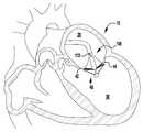
도 7 내지 도 12는 도 1 내지 도 6의 이식가능한 인공 장치가 자연 이첨판 내에 전달되고 이식되는 것을 도시한다.
도 13 내지 도 13a는 제2 실시예에 따른 다른 이식가능한 인공 장치를 도시한다.
도 14 내지 도 25는 제3 실시예에 따른 다른 이식가능한 인공 장치가 자연 이첨판 내에 전달되고 이식되는 것을 도시한다.
도 23a는 바브형 클래스프에 의해 포획된 이첨판 조직의 일부를 도시한다.
도 26은 일 실시예에 따른 이식가능한 인공 장치용 바브형 클래스프를 도시한다.
도 27은 제2 실시예에 따른 이식가능한 인공 장치용 바브형 클래스프를 도시한다.
도 28은 제3 실시예에 따른 이식가능한 인공 장치용 바브형 클래스프를 도시한다.
도 29 내지 도 31은 다양한 굽힘 단계에서의 이식가능한 인공 장치용 바브형 클래스프의 측면도를 도시한다.
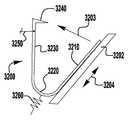
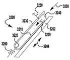
도 32는 제4 실시예에 따른 이식가능한 인공 장치용 바브형 클래스프를 도시한다.
도 33은 제5 실시예에 따른 이식가능한 인공 장치용 바브형 클래스프를 도시한다.
도 34는 제6 실시예에 따른 이식가능한 인공 장치용 바브형 클래스프를 도시한다.
도 35는 제7 실시예에 따른 이식가능한 인공 장치용 바브형 클래스프를 도시한다.
도 36은 제8 실시예에 따른 이식가능한 인공 장치용 바브형 클래스프를 도시한다.
도 37 내지 도 52는 제9 실시예에 따른 이식가능한 인공 장치용 바브형 클래스프를 도시한다.
도 53 내지 도 55는 제10 실시예에 따른 이식가능한 인공 장치용 바브형 클래스프를 도시한다.
도 56은 제11 실시예에 따른 이식가능한 인공 장치용 바브형 클래스프를 도시한다.
도 56a 및 도 56b는 도 56의 바브형 클래스프의 힌지 부분의 대안적인 실시예를 도시한다.
도 57 및 도 58은 제12 실시예에 따른 이식가능한 인공 장치용 바브형 클래스프를 도시한다.
도 57a는 도 57 및 도 58에 도시된 바브형 클래스프를 제조하는데 사용되는 편평한 절결부를 도시한다.
도 59 내지 도 63은 제13 실시예에 따른 이식가능한 인공 장치용 바브형 클래스프를 도시한다.
도 64 내지 도 68은 제14 실시예에 따른 이식가능한 인공 장치용 바브형 클래스프를 도시한다.
도 69 내지 도 73b는 이식가능한 인공물용 예시적인 바브형 클래스프에 작동 라인을 고정하기 위한 예시적인 배열을 도시한다.
도 74a 및 도 74b는 작동 라인으로 개방되는 예시적인 바브형 클래스프를 도시한다.
도 75는 작동 라인을 갖는 제9 또는 제10 실시예의 예시적인 바브형 클래스프를 도시한다.
도 76은 제15 실시예에 따른 이식가능한 인공 장치용 바브형 클래스프를 도시한다.
도 77은 제16 실시예에 따른 이식가능한 인공 장치용 바브형 클래스프를 도시한다.
도 78 및 도 79는 제17 실시예에 따른 이식가능한 장치용 바브형 클래스프를 도시한다.
도 80a 내지 도 80e는 제18 실시예에 따른 이식가능한 장치용 바브형 클래스프를 도시한다.
도 81a 내지 도 81c는 제19 실시예에 따른 이식가능한 장치용 바브형 클래스프를 도시한다.
도 82는 본 명세서에 설명된 이식가능한 장치와 함께 사용하기 위한 예시적인 작동 기구를 도시한다.These and other features and advantages of the present invention will be better understood with reference to the following description and the accompanying drawings.
1 to 6 show the implantable artificial device according to the first embodiment in various stages of development.
7-12 show that the implantable artificial device of FIGS. 1-6 is delivered and implanted in a natural spinal plate.
13-13a show another implantable artificial device according to the second embodiment.
14-25 show another implantable artificial device according to the third embodiment to be delivered and implanted in a natural spinal plate.
FIG. 23A shows a portion of the leaflet tissue captured by a barb clasp.
FIG. 26 illustrates a barbed clasp for implantable prosthetic devices according to one embodiment. FIG.
27 shows a barbed clasp for an implantable artificial device according to a second embodiment.
28 shows a barbed clasp for an implantable artificial device according to a third embodiment.
29-31 show side views of barbed clasps for implantable prosthetic devices at various bending stages.
32 shows a barbed clasp for an implantable artificial device according to a fourth embodiment.
33 illustrates a barbed clasp for an implantable artificial device according to a fifth embodiment.
Fig. 34 shows a barbed clasp for an implantable artificial device according to the sixth embodiment.
35 illustrates a barbed clasp for implantable artificial device according to the seventh embodiment.
36 shows a barbed clasp for an implantable artificial device according to the eighth embodiment.
37-52 illustrate a barbed clasp for implantable artificial device according to a ninth embodiment.
53-55 show a barbed clasp for implantable artificial device according to the tenth embodiment.
56 illustrates a barbed clasp for implantable artificial device according to the eleventh embodiment.
56A and 56B show alternative embodiments of the hinged portion of the barbed clasp of FIG. 56.
57 and 58 show a barbed clasp for implantable artificial device according to a twelfth embodiment.
FIG. 57A shows the flat cutout used to make the barbed clasps shown in FIGS. 57 and 58.
59-63 show a barbed clasp for implantable artificial device according to the thirteenth embodiment.
64 to 68 show a barbed clasp for implantable artificial device according to a fourteenth embodiment.
69-73B illustrate an exemplary arrangement for securing the actuation line to an exemplary barbed clasp for implantable artefacts.
74A and 74B show an exemplary barbed clasp that opens to the actuation line.
75 shows an exemplary barbed clasp of the ninth or tenth embodiment with an operating line.
76 illustrates a barbed clasp for implantable artificial device according to the fifteenth embodiment.
77 shows a barbed clasp for implantable artificial device according to the sixteenth embodiment.
78 and 79 show a barbed clasp for implantable device according to the seventeenth embodiment.
80A-80E illustrate a barbed clasp for implantable device according to the eighteenth embodiment.
81A-81C show a barbed clasp for implantable device according to the nineteenth embodiment.
82 illustrates an example operating mechanism for use with the implantable device described herein.
본 명세서에서 설명되는 바와 같이, 하나 이상의 구성요소가 연결, 결합, 장착, 커플링, 부착, 또는 다른 방식으로 상호 연결되는 것으로 설명될 때, 그러한 상호 연결은 구성요소 사이에서 직접적일 수 있거나, 예컨대 하나 이상의 중간 구성요소의 사용을 통해 간접적일 수 있다. 또한, 본 명세서에서 설명되는 바와 같이, "부재", "구성요소" 또는" 부분"에 대한 언급은 단일 구조 부재, 구성요소, 또는 요소로 제한되지 않을 것이지만, 구성요소, 부재 또는 요소의 조립체를 포함할 수 있다. 또한, 본 명세서에서 설명되는 바와 같이, 용어 "실질적으로" 및" 약"은 주어진 값 또는 상태(바람직하게는 10% 이내, 보다 바람직하게는 1% 이내, 가장 바람직하게는 0.1% 이내)에 적어도 근접하는(및 포함하는) 것으로 정의된다.As described herein, when one or more components are described as being connected, coupled, mounted, coupled, attached, or otherwise interconnected, such interconnections may be direct between the components, or may be, for example, It may be indirect through the use of one or more intermediate components. Further, as described herein, reference to "member", "component" or "part" will not be limited to a single structural member, component, or element, but is intended to refer to an assembly of components, members, or elements. It may include. In addition, as described herein, the terms "substantially" and "about" refer to at least a given value or condition (preferably within 10%, more preferably within 1%, most preferably within 0.1%). It is defined as near (and inclusive).
인공 장치는 접합 수단 또는 접합 요소 및 적어도 하나의 고정 수단 또는 앵커를 갖는다. 접합 요소는 자연 판막첨 사이에 더 효과적인 밀봉부를 형성하는 것을 돕기 위해 자연 심장 판막 오리피스 내에 위치설정되도록 구성되고, 이에 의해 역류를 감소 또는 방지한다. 접합 요소는 혈액에 불투과성이고, 혈액이 좌심실 또는 우심실로부터 좌심방 또는 우심방으로 각각 역류하는 것을 차단하기 위해 자연 판막첨이 심실 수축기 중에 접합 요소의 각각의 측면 상에서 함께 근접하는 것을 허용하는 구조를 가질 수 있다. 인공 장치는 2개 또는 3개의 자연 판막 판막첨에 대해 밀봉하도록 구성될 수 있는데, 즉 장치는 자연 이첨판(승모판) 및 자연 삼첨판에 사용될 수 있다. 접합 요소는 때때로 본 명세서에서 스페이서로 지칭되는데, 그 이유는 접합 요소가 완전히 폐쇄되지 않는 부적절하게 기능하는 자연 이첨판 또는 삼첨판 판막첨 사이의 공간을 채울 수 있기 때문이다.The artificial device has joining means or joining elements and at least one fastening means or anchor. The bonding element is configured to be positioned within the natural heart valve orifice to help form a more effective seal between the natural valve tips, thereby reducing or preventing backflow. The conjugation element is impermeable to blood and may have a structure that allows the blood to adjoin together on each side of the conjugation element during ventricular systolic to prevent blood from flowing back from the left or right ventricle to the left or right atrium, respectively. have. The prosthetic device may be configured to seal against two or three natural valve leaflets, ie the device may be used for natural tricuspid (mitral valve) and natural tricuspid valve. Bonding elements are sometimes referred to herein as spacers because they can fill the spaces between improperly functioning natural or tricuspid valve stems in which the bonding elements are not completely closed.
접합 요소는 다양한 형상을 가질 수 있다. 일부 실시예에서, 접합 요소는 둥근 단면 형상을 갖는 세장형 원통형 형상을 가질 수 있다. 다른 실시예에서, 접합 요소는 난형 단면 형상, 초승달 단면 형상, 또는 다양한 다른 비-원통형 형상을 가질 수 있다. 접합 요소는 좌심방 내에 또는 좌심방에 인접하여 위치설정되는 심방 또는 상부 단부, 좌심실 내에 또는 좌심실에 인접하여 위치설정되는 심실 또는 하부 단부, 및 자연 이첨판 판막첨 사이에서 연장되는 측면을 가질 수 있다. 삼첨판에서 사용하도록 구성된 실시예에서, 심방 또는 상부 단부는 우심방 내에 또는 우심방에 인접하여 위치설정되고, 심실 또는 하부 단부는 우심실 내에 또는 우심실에 인접하여 위치설정되고, 측면은 자연 삼첨판 판막첨 사이에서 연장된다.The joining elements can have various shapes. In some embodiments, the joining element can have an elongate cylindrical shape with a round cross-sectional shape. In other embodiments, the joining element may have an oval cross-sectional shape, a crescent cross-sectional shape, or various other non-cylindrical shapes. The abutment element may have an atrial or upper end positioned within or adjacent to the left atrium, a ventricle or lower end positioned within or adjacent to the left ventricle, and a side extending between the natural spinal valve annulus. In an embodiment configured for use in the tricuspid valve, the atrium or upper end is positioned within or adjacent the right atrium, the ventricle or lower end is positioned within or adjacent the right ventricle, and the sides extend between the natural tricuspid valve leaflets. do.
앵커는, 접합 요소가 2개의 자연 판막첨 사이에 위치설정되도록, 장치를 자연 이첨판 판막첨 중 하나 또는 양자 모두에 고정하도록 구성될 수 있다. 삼첨판에서 사용하도록 구성된 실시예에서, 앵커는, 접합 요소가 3개의 자연 판막첨 사이에 위치설정되도록, 삼첨판 판막첨 중 1개, 2개, 또는 3개의 삼첨판 판막첨에 장치를 고정하도록 구성된다. 일부 실시예에서, 앵커는 접합 요소의 심실 단부에 인접한 위치에서 접합 요소에 부착될 수 있다. 일부 실시예에서, 앵커는 접합 요소가 또한 부착되는 샤프트 또는 작동 와이어와 같은 작동 수단에 부착될 수 있다. 일부 실시예에서, 앵커 및 접합 요소는 샤프트 또는 작동 와이어의 종축을 따라 각각의 앵커 및 접합 요소를 개별적으로 이동시킴으로써 서로에 대해 독립적으로 위치설정될 수 있다. 일부 실시예에서, 앵커 및 접합 요소는 앵커 및 접합 요소를 샤프트 또는 작동 와이어의 종축을 따라 함께 이동시킴으로써 동시에 위치설정될 수 있다. 앵커는, 판막첨이 앵커에 의해 포획되도록, 이식될 때 자연 판막첨 뒤에 위치설정되도록 구성될 수 있다.The anchor may be configured to secure the device to one or both of the natural binary valve annulus such that the bonding element is positioned between the two natural valve annulus. In embodiments configured for use in the tricuspid valve, the anchor is configured to secure the device to one, two, or three tricuspid valve stems such that the joining element is positioned between the three natural valve tips. In some embodiments, the anchor may be attached to the junction element at a location adjacent the ventricular end of the junction element. In some embodiments, the anchor may be attached to an actuating means such as a shaft or actuating wire to which the joining element is also attached. In some embodiments, the anchor and joining elements can be positioned independently of each other by individually moving each anchor and joining element along the longitudinal axis of the shaft or actuation wire. In some embodiments, the anchors and joining elements can be positioned simultaneously by moving the anchors and joining elements together along the longitudinal axis of the shaft or actuation wire. The anchor may be configured to be positioned behind the natural valve tip when implanted so that the valve tip is captured by the anchor.
인공 장치는 전달 외피와 같은 전달 수단을 통해 이식되도록 구성될 수 있다. 접합 요소 및 앵커는 반경방향으로 압축된 상태로 압축될 수 있고, 압축 압력이 해제될 때 반경방향으로 확장된 상태로 자가 확장될 수 있다. 장치는 접합 요소와 앵커 사이에 간극을 생성하기 위해, 앵커가 초기에 계속 압축된 접합 요소로부터 반경방향으로 멀리 확장되도록 구성될 수 있다. 이어서, 간극 내에 자연 판막첨이 위치설정될 수 있다. 접합 요소는 반경방향으로 확장되어, 접합 요소와 앵커 사이의 간극을 폐쇄하고, 접합 요소와 앵커 사이의 판막첨을 포획할 수 있다. 일부 실시예에서, 앵커 및 접합 요소는 선택적으로 자가 확장하도록 구성된다. 다양한 실시예들에 대한 이식 방법들은 상이할 수 있고, 각각의 실시예에 대해 아래에서 더 충분히 논의된다. 이들 및 다른 전달 방법에 관한 추가의 정보는 각각 그 전체가 본 명세서에 참조로서 합체되어 있는 미국 특허 제8,449,599호 및 미국 특허 출원 공개 제2014/0222136호 및 제2014/0067052호, 제2016/0331523호에서 찾아볼 수 있다.The artificial device may be configured to be implanted through a delivery means such as a delivery envelope. The joining elements and anchors can be compressed in a radially compressed state and can self-expand in a radially expanded state when the compression pressure is released. The apparatus may be configured such that the anchors extend radially far from the initially continued compressed joining element to create a gap between the joining element and the anchor. The natural valve tip can then be positioned within the gap. The joining element can extend radially to close the gap between the joining element and the anchor and to capture the valve tip between the joining element and the anchor. In some embodiments, the anchor and the joining element are optionally configured to self expand. Implantation methods for the various embodiments can be different and are discussed more fully below for each embodiment. Additional information regarding these and other methods of delivery is disclosed in U.S. Patent Nos. 8,449,599 and 2014/0222136 and 2014/0067052, 2016/0331523, which are hereby incorporated by reference in their entirety. You can find it at
개시된 인공 장치는 앵커가 판막첨에 걸리게 함으로써 심방 색전이 방지되고, 자연 건삭으로부터의 장력을 이용하여 장치를 좌심방을 향해 압박하는 높은 수축기 압력에 저항한다. 확장기 동안, 장치는 좌심실 내로의 색전에 저항하기 위해 앵커에 의해 포획되는 판막첨 상에 가해지는 압축력 및 유지력에 의존할 수 있다.The disclosed prosthetic device prevents atrial embolism by causing the anchor to pinch and resists high systolic pressure that uses the tension from the natural tendon to press the device towards the left atrium. During the dilator, the device may rely on the compressive and retaining forces exerted on the valve tip captured by the anchor to resist embolism into the left ventricle.
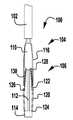
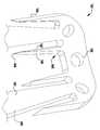
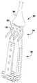
이제 도 1 내지 도 6을 참조하면, 이식가능한 인공 장치(100)가 다양한 전개 단계로 도시되어 있다. 장치(100)는 전달 외피(102)로부터 전개되고, 접합 부분(104) 및 앵커 부분(106)을 포함한다. 장치(100)의 접합 부분(104)은, 자연 이첨판의 판막첨 사이에 이식되도록 구성되고 작동 와이어 또는 샤프트(112)에 활주 가능하게 부착되는 접합 요소(110)를 포함한다. 앵커 부분(106)은 개방 및 폐쇄 상태 사이에서 작동 가능하고, 예를 들어, 패들, 파지 요소 등과 같은 매우 다양한 형태를 취할 수 있다. 작동 와이어(112)의 작동은 이식 중에 이첨판 판막첨을 포획하기 위해 장치(100)의 앵커 부분(106)을 개방 및 폐쇄한다. 작동 와이어 또는 샤프트(112)는 매우 다양한 다른 형태를 취할 수 있다. 예를 들어, 작동 와이어 또는 샤프트는 작동 와이어 또는 샤프트의 회전이 접합 부분(104)에 대해 앵커 부분(106)을 이동시키도록 스레딩될 수 있다. 또는, 작동 와이어 또는 샤프트는 작동 와이어 또는 샤프트(112)를 밀거나 당기는 것이 접합 부분(104)에 대해 앵커 부분(106)을 이동시키도록 언스레딩될 수 있다.Referring now to FIGS. 1-6, the implantable
장치(100)의 앵커 부분(106)은 부분(124, 126, 128)에 의해 캡(114)과 접합 요소(110) 사이에 연결되는 외부 패들 또는 파지 요소(120) 및 내부 패들 또는 파지 요소(122)를 포함한다. 부분(124, 126, 128)은 아래에서 설명되는 모든 위치 사이에서 이동하도록 힌지형 및/또는 가요성일 수 있다. 작동 와이어(112)는 전달 외피 및 접합 요소(110)를 통해 앵커 부분(106)의 원위 단부에서 캡(114)으로 연장된다. 작동 와이어(112)를 연장 및 후퇴시키는 것은 각각 접합 요소(110)와 캡(114) 사이의 간격을 증가 및 감소시킨다. 부착 수단 또는 칼라(도시되지 않음)는 접합 요소(110)가 작동 중에 작동 와이어(112)를 따라 활주하여 앵커 부분(106)의 패들(120, 122)을 개방 및 폐쇄하도록 전달 외피(102)에 접합 요소(110)를 제거 가능하게 부착한다.The
도 3을 참조하면, 바브형 클래스프(130)는 기부 또는 고정 아암(132), 가동 아암(134), 바브(136) 및 힌지 부분(138)을 포함한다. 고정 아암(132)은 내부 패들(122)에 부착되고, 힌지 부분(138)은 접합 요소(110)에 근접하게 배치된다. 힌지 부분(138)은 바브형 클래스프(130)의 고정 및 가동 아암(132, 134) 사이에 스프링력을 제공한다. 힌지 부분(138)은 가요성 힌지, 스프링 힌지, 피봇 힌지 등과 같은 임의의 적절한 힌지일 수 있다. 특정 실시예에서, 힌지 부분(138)은 고정 및 가동 아암(132, 134)과 일체로 형성된 가요성 재료편이다. 고정 아암(132)은 내부 패들(122)에 부착되고, 가동 아암(134)이 개방되어 바브형 클래스프(130)를 개방하고 바브(136)를 노출시킬 때 내부 패들(122)에 대해 정지 상태로 유지된다. 바브형 클래스프(130)는 가동 아암(134)의 단부에 부착된 작동 라인(116)에 장력을 인가함으로써 개방되어, 가동 아암(134)이 힌지 부분(138) 상에서 피봇하게 한다.Referring to FIG. 3, the
이식 중에, 패들(120, 122)은 패들(120, 122)과 접합 요소(110) 사이에 자연 이첨판 판막첨을 포획하기 위해 개방 및 폐쇄된다. 바브형 클래스프(130)는 바브(136)와 판막첨을 결합시키고 가동 및 고정 아암(134, 132) 사이에서 판막첨을 핀칭함으로써 자연 판막첨을 추가로 고정한다. 바브형 클래스프(130)의 바브(136)는 판막첨과의 마찰을 증가시키거나, 또는 판막첨을 부분적으로 또는 완전히 천공할 수 있다. 작동 라인(116)은 각각의 바브형 클래스프(130)가 독립적으로 개방 및 폐쇄될 수 있도록 독립적으로 작동될 수 있다. 독립적인 동작은 하나의 판막첨이 한 번에 포획될 수 있게 하거나, 또는 다른 판막첨에 대한 성공적인 파지를 변경하지 않고, 불충분하게 포획된 판막첨 상의 클래스프(130)의 재배치를 허용한다. 바브형 클래스프(130)는 서로 독립적으로 개방 및 폐쇄될 뿐만 아니라 내부 패들(122)의 위치와 독립적으로 완전히 개방 및 폐쇄될 수 있고, 이에 의해 특별한 상황이 요구됨에 따라 판막첨이 다양한 위치에서 포획될 수 있게 한다.During implantation, the
바브형 클래스프(130)는 전달 외피(102)를 통해 바브형 클래스프(130)의 단부까지 연장되는 부착된 작동 수단 또는 작동 라인(116)을 당김으로써 독립적으로 개방될 수 있다. 작동 라인(116)은 예를 들어 라인, 봉합사, 와이어, 로드, 카테터 등과 같은 매우 다양한 형태를 취할 수 있다. 바브형 클래스프(130)는 폐쇄 위치에서 바브형 클래스프(130)가 포획된 자연 판막첨에 핀칭 힘을 계속 제공하도록 스프링 로딩될 수 있다. 이 핀칭 힘은 내부 패들(122)의 위치에 관계없이 일정하게 유지된다. 바브형 클래스프(130)의 바브(136)는 자연 판막첨을 추가로 고정하기 위해 자연 판막첨을 뚫을 수 있다.The
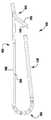
이제 도 1을 참조하면, 장치(100)는 전달 외피로부터의 전개를 위한 신장된 또는 완전 개방 상태로 도시된다. 완전 개방 위치가 최소의 공간을 차지하고 최소의 카테터가 사용될 수 있게 하기 때문에(또는 주어진 카테터 크기에 대해서 가장 큰 장치(100)가 사용될 수 있게 하기 때문에), 장치(100)는 완전 개방 위치의 전달 외피 내에 로딩된다. 신장된 상태에서, 캡(114)은 앵커 부분(106)의 패들(120, 122)이 반전되거나 또는 완전히 개방되도록 접합 요소(110)로부터 이격된다. 일부 실시예에서, 외부 및 내부 패들(120, 122)의 내부 사이에 형성된 각도는 대략 180도이다. 바브형 클래스프(130)는, 바브(136)(도 3)가 환자의 심장 내의 외피 또는 조직을 캐치하거나 또는 손상시키지 않도록, 전달 외피(102)를 통한 전개 중에 폐쇄 상태로 유지된다.Referring now to FIG. 1,
이제 도 1a를 참조하면, 장치(100)는 도 1과 유사하지만, 바브형 클래스프(130)가 완전 개방 위치에 있는 상태에서, 바브형 클래스프(130)의 고정 및 가동 부분 사이의 약 140도 내지 약 200도, 약 170도 내지 약 190도, 또는 약 180도 범위의 신장된 엉킴 해제 상태로 도시된다. 장치(100) 및 클래스프(130)를 완전히 개방하는 것은 장치(100)의 이식 동안 환자의 해부조직으로부터의 엉킴 해제의 용이성을 개선하는 것으로 밝혀졌다.Referring now to FIG. 1A, the
이제 도 2를 참조하면, 장치(100)는 단축된 또는 완전 폐쇄된 상태로 도시되어 있다. 단축된 상태의 장치(100)의 소형 크기는 심장 내의 더 용이한 조작 및 배치를 가능하게 한다. 장치(100)를 신장된 상태에서 단축된 상태로 이동시키기 위해, 작동 와이어(112)가 후퇴되어 접합 요소(110)를 향해 캡(114)을 당긴다. 외부 패들(120)과 내부 패들(122) 사이의 힌지 또는 가요성 연결부(126)는, 외부 패들(120)에 작용하는 압축력이 캡(114)으로부터 접합 요소(110)를 향해 후퇴되어 패들 또는 파지 요소(120, 122)가 반경방향 외향으로 이동하게 하는 이동으로 제한된다. 개방 위치로부터 폐쇄 위치로의 이동 중에, 외부 패들(120)은 작동 와이어(112)와 예각을 유지한다. 외부 패들(120)은 폐쇄 위치를 향해 선택적으로 편향될 수 있다. 동일한 운동 중의 내부 패들(122)은, 이들이 개방 상태에서 접합 요소(110)로부터 멀리 배향되고 폐쇄 상태에서 접합 요소(110)의 측면을 따라서 접힘에 따라 상당히 더 큰 각도를 통해 이동한다. 특정 실시예에서, 내부 패들(122)은 외부 패들(120)보다 더 얇고 및/또는 더 좁고, 내부 패들(122)에 연결된 힌지 또는 가요성 부분(126, 128)은 외부 패들(124)을 캡(114)에 연결하는 힌지 또는 가요성 부분(124)보다 더 많은 이동을 허용하도록 더 얇고 및/또는 더 가요성이다.Referring now to FIG. 2, the
이제 도 3 내지 도 5를 참조하면, 장치(100)는 부분적으로 개방된 포획 준비 상태로 도시된다. 완전 폐쇄 상태로부터 부분 개방 상태로 전이하기 위해, 작동 와이어(112)는 캡(114)을 접합 요소(110)로부터 멀리 밀어내도록 연장되고, 이에 의해 외부 패들(120)을 당기고, 이는 차례로 내부 패들(122)을 당겨, 앵커 부분(106)이 부분적으로 펼쳐지게 한다. 작동 라인(116)은 또한 판막첨이 포획될 수 있도록 클래스프(130)를 개방하기 위해 후퇴된다.Referring now to FIGS. 3-5, the
이제 도 4를 참조하면, 작동 라인(116) 중 하나는 클래스프(130) 중 하나가 폐쇄되게 하도록 연장된다. 이제 도 5를 참조하면, 다른 작동 라인(116)은 다른 클래스프(130)가 폐쇄되게 하도록 연장된다. 작동 라인(116) 중 하나 또는 모두는 바브형 클래스프(130)를 반복적으로 개방 및 폐쇄하도록 반복적으로 작동될 수 있다.Referring now to FIG. 4, one of the
이제 도 6을 참조하면, 장치(100)는 완전히 폐쇄되고 전개된 상태로 도시되어 있다. 전달 외피(102) 및 작동 와이어(112)는 후퇴되고 패들(120, 122) 및 클래스프(130)는 완전 폐쇄 위치로 유지된다. 일단 전개되면, 장치(100)는 기계적 래치로 완전 폐쇄 위치에 유지되거나, 또는 강철, 다른 금속, 플라스틱, 복합재 등과 같은 스프링 재료 또는 니티놀과 같은 형상 기억 합금의 사용을 통해 폐쇄되게 유지되도록 편향될 수 있다. 예를 들어, 힌지형 또는 가요성 부분(124, 126, 128, 138) 및/또는 내부 및 외부 패들(122), 및/또는 추가의 편향 구성요소(도 13의 구성요소(224) 참조)는, 강철과 같은 금속 또는 와이어, 시트, 튜빙, 또는 레이저 소결 분말로 제조된 니티놀과 같은, 형상 기억 합금으로 형성될 수 있고, 외부 패들(120)을 접합 요소(110) 주위에서 폐쇄된 상태로 그리고 바브형 클래스프(130를 자연 판막첨 주위에서 핀칭된 상태로 유지하도록 편향된다. 유사하게, 바브형 클래스프(130)의 고정 및 가동 아암(132, 134)은 판막첨을 핀칭하도록 편향된다. 특정 실시예에서, 힌지 부분(124, 126, 128, 138) 및/또는 내부 및 외부 패들(122), 및/또는 추가의 편향 구성요소(도 13의 구성요소(224) 참조)는, 이식 후에 장치를 폐쇄 상태로 유지하기 위해, 금속 또는 중합체 재료와 같은 임의의 다른 적절한 탄성 재료로 형성될 수 있다.Referring now to FIG. 6, the
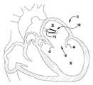
이제 도 7 내지 도 12를 참조하면, 도 1 내지 도 6의 이식가능한 장치(100)는 심장(10)의 자연 이첨판(40) 내에 전달되고 이식되는 것으로 도시되어 있다. 이제 도 7을 참조하면, 전달 외피는 격막을 통해 좌심방(20) 내로 삽입되고, 장치(100)는 완전 개방 상태에서 전달 외피로부터 전개된다. 작동 와이어(112)는 이어서 후퇴되어 장치(100)를 도 8에 도시된 완전 폐쇄 상태로 이동시킨다. 도 9에서 알 수 있는 바와 같이, 장치(100)는 심실(30) 내로의 이첨판(40) 내의 위치로 이동되고, 판막첨(42, 44)이 포획될 수 있도록 부분 개방된다. 이제 도 10을 참조하면, 작동 라인(116)이 클래스프(130) 중 하나를 폐쇄하도록 연장되어, 판막첨(42)을 포획한다. 도 11은 다른 작동 라인(116)이 다른 클래스프(130)를 폐쇄하도록 연장되어, 나머지 판막첨(44)을 포획하는 것을 도시한다. 마지막으로, 도 12에서 알 수 있는 바와 같이, 전달 외피(102) 및 작동 와이어(112)는 이어서 후퇴되고, 장치(100)는 완전히 폐쇄되고 자연 이첨판(400) 내에 전개된다.Referring now to FIGS. 7-12, the
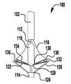
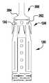
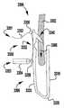
이제 도 13을 참조하면, 이식가능한 인공 장치(200)가 도시되어 있다. 이식가능한 장치(200)는 도 1 내지 도 12에 개략적으로 도시된 장치(100)가 취할 수 있는 많은 상이한 구성 중 하나이다. 장치(200)는 전달 외피(도시되지 않음)로부터 전개되고, 접합 부분(204) 및 앵커 부분(206)을 포함한다. 완전 개방 위치가 최소의 공간을 차지하고 최소의 카테터가 사용될 수 있게 하기 때문에(또는 주어진 카테터 크기에 대해서 가장 큰 장치(200)가 이용될 수 있게 하기 때문에), 장치(200)는 완전 개방 위치의 전달 외피 내에 로딩된다. 장치의 접합 부분(204)은 작동 와이어 또는 샤프트(212)에 활주 가능하게 부착되는 자연 이첨판의 판막첨 사이에 이식을 위한 접합 요소(210)를 포함한다. 작동 와이어(212)의 작동은 이식 중에 이첨판 판막첨을 포획하기 위해 장치(200)의 앵커 부분(206)을 개방 및 폐쇄한다.Referring now to FIG. 13, an implantable
장치(200)의 앵커 부분(206)은 캡(214) 및 접합 요소(210)에 힌지식으로 연결되는 외부 패들(220) 및 내부 패들(222)을 포함한다. 작동 와이어(212)는 앵커 부분(206)의 원위 단부에서 전달 외피(도시되지 않음), 칼라(211), 및 접합 요소(210)를 통해 캡(214)으로 연장된다. 작동 와이어(212)를 연장 및 후퇴시키는 것은 각각 접합 요소(210)와 캡(214) 사이의 간격을 증가 및 감소시킨다. 칼라(211)는, 장치(200)의 이식 동안 작동 와이어 또는 샤프트(212) 주위에 밀봉부를 형성하고, 이식 후에 접합 요소(210)의 내부를 통한 혈류에 대해, 작동 와이어(212)가 제거될 때 장치(200)를 실질적으로 폐쇄하도록 밀봉 차단하는 칼라 밀봉부(213)를 선택적으로 포함한다. 일부 실시예에서, 칼라(2011)는 접합 요소(210)가 작동 중에 작동 와이어(212)를 따라 활주하여 앵커 부분(206)의 패들(220, 222)을 개방 및 폐쇄하도록 전달 외피에 접합 요소(200)를 제거 가능하게 결합 및 부착한다. 일부 실시예에서, 칼라(2011)는 작동 와이어(212)에 의해 접합 요소(2010) 주위에 폐쇄된 상태로 유지되어, 작동 와이어(212)의 제거가 칼라의 핑거(도시되지 않음)가 개방될 수 있게 하여, 접합 요소(210)를 해제한다. 일부 실시예에서, 캡(2014)은 접합 요소(210)의 개구(215) 내측에 끼워지는 밀봉부(216) 및/또는 삽입체(218)를 선택적으로 포함하고, 접합 요소(210)는 중공 내부를 갖는다. 밀봉부(216) 및/또는 삽입체(218)는 작동 와이어(212)가 인출되고 장치(200)가 이식될 때 접합 요소(210)를 혈액 유동에 대해 실질적으로 폐쇄된 상태로 유지한다.The
접합 요소(210) 및 패들(220, 222)은 메시, 직조, 편조, 또는 임의의 다른 적절한 방식으로 형성될 수 있는 커버링으로 형성된다. 커버링은 천, 형상 설정 능력을 제공하기 위해, 니티놀과 같은 형상 기억 합금 와이어, 또는 인체 내의 이식에 적절한 임의의 다른 가요성 재료일 수 있다. 패들 프레임(224)은 외부 패들(222)과 접합 요소(210) 사이에 추가의 핀칭 힘을 제공하고, 접합 요소(210)와 판막첨 사이의 더 양호한 밀봉을 위해 접합 요소(210)의 측면 주위의 판막첨을 감싸는 것을 돕는다. 일부 실시예에서, 커버링은 패들 프레임(224) 주위에서 연장된다.
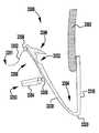
바브형 클래스프(230)는 기부 또는 고정 아암(232), 가동 아암(234), 바브(236) 및 힌지 부분(238)을 포함한다. 고정 아암(232)은 내부 패들(222)에 부착되고, 힌지 부분(238)은 접합 요소(210)에 근접하게 배치된다. 고정 아암(232)은 봉합사(도시되지 않음)를 갖는 구멍 또는 슬롯(233)을 통해 내부 패들(222)에 부착된다. 고정 아암(232)은 나사 또는 다른 체결구, 크림핑된 슬리브, 기계적 래치 또는 스냅, 용접, 접착제 등과 같은 임의의 적절한 수단으로 내부 패들(222)에 부착될 수 있다. 고정 아암(232)은 가동 아암(234)이 바브형 클래스프(230)를 개방하고 바브(236)를 노출시키도록 개방될 때 내부 패들(222)에 대해 정지 상태로 유지된다. 바브형 클래스프(230)는 가동 아암(234)의 단부에 배치된 구멍(235)에 부착된 작동 라인(도시되지 않음)에 장력을 인가함으로써 개방되어, 가동 아암(234)이 힌지 부분(238) 상에서 피봇하게 한다.The
이식 중에, 패들(220, 222)은 개방 및 폐쇄되어 패들(220, 222)과 접합 요소(210) 사이에 자연 이첨판 판막첨을 포획한다. 바브형 클래스프(230)는 바브(236)와 판막첨을 결합시키고 가동 및 고정 아암(234, 232) 사이에 판막첨을 핀칭함으로써 자연 판막첨을 추가로 고정한다. 바브형 클래스프(230)의 바브(236)는 판막첨과의 마찰을 증가시키거나, 또는 판막첨을 부분적으로 또는 완전히 천공할 수 있다. 작동 라인은 각각의 바브형 클래스프(230)가 독립적으로 개방 및 폐쇄될 수 있도록 독립적으로 작동될 수 있다. 독립적인 동작은 하나의 판막첨이 한 번에 포획될 수 있게 하거나, 다른 판막첨에 대한 성공적인 파지를 변경하지 않고, 불충분하게 포획된 판막첨 상의 클래스프(230)의 재배치를 허용한다. 바브형 클래스프(230)는 서로 독립적으로 개방 및 폐쇄될 뿐만 아니라 내부 패들(222)의 위치와 독립적으로 완전히 개방 및 폐쇄될 수 있고, 이에 의해 특별한 상황이 요구됨에 따라 판막첨이 다양한 위치에서 포획될 수 있게 한다.During implantation, the
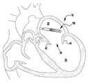
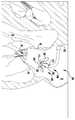
이제 도 14 내지 도 25를 참조하면, 이식가능한 장치(300)가 심장(10)의 자연 이첨판(40) 내에 전달되고 이식되는 것으로 도시되어 있다. 장치(300)는 접합 요소(310), 클래스프(330), 내부 패들(322) 및/또는 외부 패들(320) 위에 커버링을 갖지만, 장치(300)는 도 13의 이식가능한 장치(200)와 유사하다. 장치(300)는 전달 외피(302)로부터 전개되고, 접합 부분(304) 및 앵커 부분(306)을 포함한다. 장치의 접합 부분(304)은 작동 와이어 또는 샤프트(312)에 활주 가능하게 부착되는 자연 이첨판의 판막첨 사이에 이식을 위한 접합 요소(310)를 포함한다. 작동 와이어 또는 샤프트(312)의 작동은 장치(300)의 앵커 부분(306)을 개방 및 폐쇄하여 이식 동안 이첨판 판막첨을 포획한다.Referring now to FIGS. 14-25, the
장치(300)의 앵커 부분(306)은 캡(314) 및 접합 요소(310)에 유연하게 연결되는 외부 패들(320) 및 내부 패들(322)을 포함한다. 작동 와이어(312)는 앵커 부분(306)의 원위 단부에서 칼라(303)(도 20 참조), 전달 외피(302), 및 접합 요소(310)를 통해 캡(314)으로 연장된다. 작동 와이어(312)를 연장 및 후퇴시키는 것은 각각 접합 요소(310)와 캡(314) 사이의 간격을 증가 및 감소시킨다. 칼라(303)의 핑거는 접합 요소(310)를 전달 외피(302)에 제거 가능하게 부착하여, 접합 요소(310)가 작동 중에 작동 와이어(312)를 따라 활주하여 앵커 부분(306)의 패들(320, 322)을 개방 및 폐쇄한다. 일부 실시예에서, 칼라(303)는 작동 와이어(312)에 의해 접합 요소(310) 주위에서 폐쇄된 상태로 폐쇄되게 유지되어, 작동 와이어(312)의 제거가 칼라(303)의 핑거가 개방되게 하여, 접합 요소(310)를 해제한다.The
접합 요소(310) 및 패들(320, 322)은 메시, 직조, 편조, 또는 임의의 다른 적절한 방식으로 형성될 수 있는 가요성 재료로 형성된다. 가요성 재료는 천, 형상 설정 능력을 제공하기 위해, 니티놀과 같은 형상 기억 합금 와이어, 또는 인체 내의 이식에 적절한 임의의 다른 가요성 재료일 수 있다.
바브형 클래스프(330)는 기부 또는 고정 아암(332), 가동 아암(334), 바브(336)(도 20 참조), 및 힌지 부분(338)을 포함한다. 고정 아암(332)은 내부 패들(322)에 부착되고, 힌지 부분(338)은 접합 요소(310)에 근접하게 배치된다. 봉합사(도시되지 않음)는 고정 아암(332)을 내부 패들(322)에 부착한다. 고정 아암(332)은 나사 또는 다른 체결구, 크림핑된 슬리브, 기계적 래치 또는 스냅, 용접, 접착제 등과 같은 임의의 적절한 수단으로 내부 패들(322)에 부착될 수 있다. 고정 아암(332)은 가동 아암(334)이 바브형 클래스프(330)를 개방하고 바브(336)를 노출시키도록 개방될 때 정지 상태로 유지된다. 바브형 클래스프(330)는 가동 아암(334)의 단부에 부착된 작동 라인(316)에 장력을 인가함으로써 개방되어, 가동 아암(334)이 힌지 부분(338) 상에서 피봇하게 한다.The
이식 중에, 패들(320, 322)은 패들(320, 322)과 접합 요소(310) 사이에 자연 이첨판 판막첨을 포획하도록 개방 및 폐쇄된다. 외부 패들(320)은 판막첨을 보다 확실하게 파지하기 위해 접합 요소(310)의 만곡된 형상 주위에 맞는 넓은 만곡된 형상을 갖는다. 외부 패들(320)의 만곡된 형상 및 라운딩된 연부는 또한 판막첨 조직의 파열을 방지한다. 바브형 클래스프(330)는 바브(336)와 판막첨을 결합시키고 가동 및 고정 아암(334, 332) 사이에 판막첨을 핀칭함으로써 자연 판막첨을 추가로 고정한다. 바브형 클래스프(330)의 바브(336)는 판막첨과의 마찰을 증가시키거나, 또는 판막첨을 부분적으로 또는 완전히 천공할 수 있다. 작동 라인은 각각의 바브형 클래스프(330)가 독립적으로 개방 및 폐쇄될 수 있도록 독립적으로 작동될 수 있다. 독립적인 동작은 하나의 판막첨이 한 번에 포획될 수 있게 하거나, 다른 판막첨에 대한 성공적인 파지를 변경하지 않고, 불충분하게 포획된 판막첨 상의 클래스프(330)의 재배치를 허용한다. 바브형 클래스프(330)는 서로 독립적으로 개방 및 폐쇄될 뿐만 아니라 내부 패들(322)의 위치와 독립적으로 완전히 개방 및 폐쇄될 수 있고, 이에 의해 특별한 상황이 요구됨에 따라 판막첨이 다양한 위치에서 포획될 수 있게 한다.During implantation, the
완전 개방 위치가 최소의 공간을 차지하고 최소의 카테터가 사용될 수 있게 하기 때문에(또는 주어진 카테터 크기에 대해서 가장 큰 장치(300)가 사용될 수 있게 하기 때문에), 장치(300)는 완전 개방 위치의 전달 외피 내에 로딩된다. 이제 도 14를 참조하면, 전달 외피는 격막을 통해 좌심방(20) 내로 삽입되고, 장치(300)는 완전 개방 상태에서 전달 외피(302)로부터 전개된다. 작동 와이어(312)는 이어서 후퇴되어 도 15 및 도 16에 도시된 완전 폐쇄 상태로 장치(300)를 이동시키고, 이어서 도 17에 도시된 바와 같이 이첨판(40)을 향해 조종된다. 이제 도 18을 참조하면, 장치(300)가 이첨판(40)과 정렬될 때, 작동 와이어(312)는 패들(320, 322)을 부분 개방 위치로 개방하도록 연장되고, 작동 라인(316)은 판막첨 포획을 준비하기 위해 바브형 클래스프(330)를 개방하도록 후퇴된다. 다음에, 도 19 및 도 20에 도시된 바와 같이, 부분 개방 장치(300)는 판막첨이 내부 패들(322)과 접합 요소(310) 사이에 그리고 개방 바브형 클래스프(330) 내부에 적절하게 위치설정될 때까지 이첨판(40)을 통해 삽입된다. 도 21은 하나의 클래스프(330)의 바브(336)가 판막첨(44) 중 하나를 누락하였지만, 양 클래스프(330)가 폐쇄된 장치(300)를 도시하고 있다. 도 22 및 도 23에서 알 수 있는 바와 같이, 위치에서 벗어난 클래스프(330)는 누락된 판막첨(44)을 적절히 포획하기 위해 개방되고 다시 폐쇄된다. 양 판막첨(42, 44)이 적절하게 포획될 때, 작동 와이어(312)는 장치(300)를 도 24에 도시된 완전 폐쇄 위치로 이동시키도록 후퇴된다. 장치(300)가 자연 이첨판(40) 내에 완전히 이식된 상태에서, 작동 와이어(312)는 접합 요소(310)의 상부 단부 또는 플레이트(311)로부터 칼라(303)를 해제하도록 인출된다. 일단 전개되면, 장치(300)는 래치와 같은 기계적 수단으로 완전 폐쇄 위치에서 유지될 수 있거나, 또는 강철과 같은 스프링 재료, 및/또는 니티놀과 같은 형상 기억 합금의 사용을 통해 폐쇄 상태로 유지되도록 편향될 수 있다. 예를 들어, 패들(320, 322)은 강철 또는 와이어, 시트, 튜빙, 또는 레이저 소결 분말로 제조된 니티놀 형상 기억 합금으로 형성될 수 있고, 외부 패들(320)을 접합 요소(310) 주위에서 폐쇄된 상태로 그리고 바브형 클래스프(330)를 자연 판막첨 주위에서 핀칭된 상태로 유지하도록 편향된다.Because the full open position occupies the minimum space and allows the smallest catheter to be used (or allows the
이제 도 23a를 참조하면, 클래스프(330) 중 하나에 의해 포획된 판막첨(42, 44) 중 하나의 확대도가 도시된다. 판막첨(42, 44)은 클래스프(330)의 가동 및 고정 아암(334, 332) 사이에 포획된다. 도 23a에 도시된 바와 같이, 판막첨(42, 44)의 조직은 바브(336)에 의해 뚫리지 않지만, 일부 실시예에서 바브(336)는 판막첨(42, 44)을 부분적으로 또는 완전히 뚫을 수 있다. 가동 아암(334)에 대한 바브(336)의 각도 및 높이는 클래스프(330) 내에 판막첨(42, 44)을 고정하는 것을 돕는다. 특히, 임플란트를 자연 판막첨으로부터 당기는 힘은 바브(336)가 조직과 더 결합하도록 촉진하여, 더 양호한 보유를 보장할 것이다. 클래스프(330) 내의 판막첨(42, 44)의 보유는 클래스프(330)가 폐쇄될 때 바브(336) 근처의 고정 아암(332)의 위치에 의해 더 개선된다. 이러한 배열에서, 조직은 고정 및 가동 아암(332, 334) 및 바브(336)에 의해 S자 형상의 구불구불한 경로 내로 형성된다. 따라서, 판막첨을 클래스프(330)로부터 멀리 당기는 힘은, 판막첨이 빠져나갈 수 있기 전에, 조직이 바브(336)와 더 결합하는 것을 촉진할 것이다.Referring now to FIG. 23A, an enlarged view of one of the
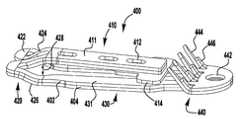
이제 도 26을 참조하면, 상술된 장치(100, 200, 300)와 같은, 이식가능한 인공 장치에 사용하기 위한 예시적인 바브형 클래스프(400)가 도시된다. 바브형 클래스프(400)는 상부 층(402) 및 하부 층(404)으로 형성된다. 클래스프(400)의 2층 설계는 더 얇은 재료의 시트가 사용되는 것을 허용하고, 이에 의해 자연 판막 판막첨을 성공적으로 보유하는데 필요한 클래스프(400)의 강도를 유지하면서, 단일의 두꺼운 시트로 형성된 클래스프에 비해 클래스프(400)의 가요성을 향상시키는 데 사용될 수 있다.Referring now to FIG. 26, an exemplary
바브형 클래스프(400)는 고정 아암(410), 힌지형 부분(420), 및 바브형 부분(440)을 갖는 가동 아암(430)을 포함한다. 상부 및 하부 층(402, 404)은 유사한 형상을 가지며, 특정 실시예에서는 바브형 단부(440)에서 서로 부착된다. 힌지형 부분(420)은 고정 및 가동 아암(410, 430)이 바브형 클래스프(400)가 폐쇄 상태에 있을 때 서로를 향해 편향되도록 스프링-로딩된다. 이식가능한 인공 장치에 조립될 때, 고정 아암(410)은 인공 장치의 일부에 부착된다. 클래스프(400)는 힌지 부분(420)의 스프링력이 극복될 때까지 가동 아암(430)에 부착된 작동 라인을 당김으로써 개방된다.The
고정 아암(410)은 가동 아암(430)의 2개의 측면 빔(431) 사이에서 힌지형 부분(420)으로부터 연장되는 재료의 설부(411)로 형성된다. 설부(411)는, 측면 빔(431)을 넘어 위치된 중립 위치로부터 측면 빔(431)과 실질적으로 평행한 예비로딩된 위치로 설부(411)를 이동시키기 위해서 힘이 인가되어야 하도록, 힌지 부분(420)에 의해 측면 빔(431) 사이에서 편향된다. 설부(411)는 설부(411)에 부착되고 측면 빔(431)과 결합하도록 외향으로 연장되는 T-형상의 크로스바(414)에 의해 예비로딩된 위치에 유지된다. 특정 실시예에서, 설부가 중립 위치에 있을 때 고정 및 가동 아암(410, 430) 사이의 각도는 약 30 내지 약 100도, 30 내지 약 90도, 또는 약 30 내지 약 60도, 또는 약 40 내지 약 50도, 또는 약 45도이다.The fixed
설부(411)는 이식가능한 장치에 고정 아암(410)을 부착하는 봉합사(도시되지 않음)를 수용하기 위한 구멍(412)을 포함한다. 고정 아암(410)은 나사 또는 다른 체결구, 크림핑된 슬리브, 기계적 래치 또는 스냅, 용접, 접착제 등과 같은, 다양한 부착 수단에 의해 이식가능한 장치에 부착될 수 있다. 특정 실시예에서, 구멍(412)은 이식가능한 장치에 클래스프(400)를 부착하는 봉합사를 손상시키지 않으면서, 층(402, 404)의 활주를 수용하기 위한 세장형 슬롯 또는 난형 구멍이다.The
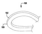
힌지 부분(420)은 고정 아암(410)의 설부(411)로부터 가동 아암(430)의 측면 빔(431)으로 연장되는 2개의 빔 루프(422)에 의해 형성된다. 특정 실시예에서, 빔 루프(422)는 추가의 가요성을 제공하기 위해 설부(411) 및 측면 빔(431)보다 좁다. 빔 루프(422)는 각각 설부(411)로부터 연장되는 중심 부분(424) 및 측면 빔(431)으로 연장되는 외부 부분(426)을 포함한다. 빔 루프(422)는 중심 및 외부 부분(424, 426)을 반대 방향으로 굴곡시킴으로써 약간 나선형 또는 헬리컬 형상으로 굴곡되고, 이에 의해 설부(411)와 측면 빔(431) 사이에 오프셋 또는 단차 거리(428)를 형성한다. 단차 거리(428)는 그것이 포획된 후에 이첨판의 자연 판막첨을 수용하기 위해 아암(410, 430) 사이에 공간을 제공한다. 특정 실시예에서, 단차 거리(428)는 약 0.5 밀리미터 내지 약 1 밀리미터, 또는 약 0.75 밀리미터이다.
평면도에서 볼 때, 빔 루프는 "오메가형" 형상을 갖는다. 빔 루프(422)의 이러한 형상은 고정 및 가동 아암(410, 430)이 클래스프 재료를 소성 변형시키지 않으면서 서로에 대해 상당히 많이 이동할 수 있게 한다. 예를 들어, 특정 실시예에서, 설부(411)는 클래스프 재료를 소성 변형시키지 않고 가동 아암(430)으로부터 약 140도 내지 약 200도, 약 170도 내지 약 190도, 또는 약 180도의 범위인 완전 개방 위치로 가동 아암(430)을 넘어 대략 45도인 중립 위치로부터 피봇될 수 있다. 특정 실시예에서, 클래스프 재료는 폐쇄 위치에서 고정 및 가동 아암 사이에 가해지는 핀치 힘을 감소시키거나 실질적으로 감소시키지 않으면서 개방 중에 소성 변형된다.When viewed in plan view, the beam loop has an "omega" shape. This shape of the
설부(411)를 예비로딩하는 것은 클래스프(400)가 폐쇄될 때 자연 판막첨에 대한 핀칭 또는 클립핑 힘을 유지할 수 있게 하고, 또한 자연 판막첨을 더 쉽게 포획하기 위해 넓게 개방되게 할 수 있다. 설부(411)의 예비로딩은 폐쇄될 때 핀칭 힘을 거의 또는 전혀 제공하지 않는 종래 기술의 클립에 비해 상당한 장점을 제공한다. 추가로, 클래스프(400)는 폐쇄될 때 충분한 핀칭 힘을 계속 유지하면서, 판막첨 상의 재배치를 위해서 반복적으로 개방 및 폐쇄될 수 있기 때문에, 클래스프(400)를 스프링력으로 폐쇄하는 것은 1회 로킹 폐쇄 기구를 이용하는 클립에 비해 상당한 개선이다.
가동 아암(430)의 바브형 부분(440)은 아일릿(442), 바브(444), 및 바브 지지부(446)를 포함한다. 클래스프(400)가 개방될 때, 클래스프(400)의 바브형 부분을 가동 아암(430)의 단부에 위치설정하는 것은 바브(444)와 고정 아암(410) 사이의 공간을 증가시키고, 이에 의해 클래스프(400)가 이식 중에 판막첨을 성공적으로 포획하는 능력을 향상시킨다. 이 거리는 또한 바브(444)가 재배치를 위해 판막첨으로부터 더 신뢰성 있게 분리될 수 있게 한다. 특정 실시예에서, 클래스프의 바브는 핀치 힘 및 국부적 판막첨 응력을 더 분배하도록 종방향으로 엇갈릴 수 있다.
바브(444)는 힌지 부분(420)으로부터 동일한 거리로 측방향으로 이격되어 있고, 이는 또한 클래스프가 종방향 로우로 배열된 바브보다 판막첨 포획에 대해 더 강건하게 만들면서, 판막첨 조직에 대한 우수한 핀칭 힘의 분포를 제공한다. 일부 실시예에서, 바브(444)는 핀치 힘 및 국부적 판막첨 응력을 더 분배하도록 엇갈릴 수 있다.The
바브(444)는 하부 층(404)으로 형성되고, 바브 지지부(446)는 상부 층으로 형성된다. 특정 실시예에서, 바브는 상부 층(402)으로 형성되고 바브 지지부는 하부 층(404)으로 형성된다. 2개의 층(402, 404) 중 하나에만 바브(444)를 형성하는 것은 바브가 더 얇아질 수 있게 하고 따라서 두께가 2배인 동일한 재료로 형성된 바브보다 효과적으로 더 예리하게 되게 한다. 바브 지지부(446)는 바브(444)의 하부 부분을 따라 연장되어 바브(444)를 강성화하여, 판막첨 조직의 침투 및 보유를 더 향상시킨다. 특정 실시예에서, 바브(444)의 단부는 임의의 적절한 연마 수단을 사용하여 더 예리해진다.The
바브(444)는, 이들이 최소 핀칭 또는 클립핑 힘으로 자연 판막첨의 조직에 용이하게 침투하도록, 가동 아암(430)으로부터 멀리 경사진다. 바브(444)는 약 45도 내지 약 75도, 또는 약 45도 내지 약 60도, 또는 약 48도 내지 약 56도, 또는 약 52도의 각도로 가동 아암으로부터 연장된다. 바브(444)의 각도는, 임플란트를 자연 판막첨으로부터 당기는 힘이 바브(444)가 조직과 더 결합하여 더 양호한 보유를 보장하는 것을 촉진하는 추가의 이점을 제공한다. 클래스프(400) 내의 판막첨의 보유는 클래스프(400)가 폐쇄될 때 바브(444) 근처의 T-형상의 크로스바(414)의 위치에 의해 더 개선된다. 이러한 배열에서, 바브(444)에 의해 뚫려진 조직이 크로스바(414) 위치에서 가동 아암(430)에 대해서 핀칭되고, 이에 의해 이것이 바브(444) 위를 통과함에 따라 조직을 S-형상의 구불구불한 경로 내로 형성한다. 따라서, 판막첨을 클래스프(400)로부터 멀리 당기는 힘은, 판막첨이 빠져나갈 수 있기 전에, 조직이 바브(444)와 더 결합하는 것을 촉진할 것이다.The
클래스프(400)의 각각의 층(402, 404)은 니티놀과 같은, 형상 기억 합금의 시트로부터 레이저 절단된다. 상부 층(402)은 하부 층(404)에 정렬되고 부착된다. 특정 실시예에서, 층(402, 404)은 가동 아암(430)의 바브형 단부(440)에 부착된다. 예를 들어, 층(402, 404)은 층의 나머지가 서로에 대해 활주하게 하도록, 바브형 단부(440)에서만 부착될 수 있다. 고정 아암(410), 바브(444), 및 바브 지지부(446), 및 빔 루프(422)와 같은, 조합된 층(402, 404)의 부분은 원하는 위치로 굴곡된다. 층(402, 404)은 함께 굽혀지고 형상 설정될 수 있거나, 또는 개별적으로 굴곡 및 형상 설정된 다음 함께 결합될 수 있다. 이어서, 클래스프(400)가 형상 설정 프로세스를 거쳐서, 재료의 내력이 외력에 의해 변형된 후에 설정 형상으로 복귀되는 경향이 있을 것이다. 형상 설정 후에, 설부(411)는 크로스바(414)가 부착될 수 있도록 그 예비로딩된 위치로 이동된다. 결과적으로, 클래스프(400)는 전달 외피를 통해 전달을 위해 완전히 평탄화되고, 일단 심장 내에서 전개되면 확장되도록 허용될 수 있다.Each
클래스프(400)는 가동 아암(430)에 부착된 작동 라인, 봉합사, 와이어, 로드, 카테터 등(도시되지 않음)과 같은 작동 수단에 장력을 인가 및 해제함으로써 개방 및 폐쇄된다. 봉합사는 가동 아암(430)의 바브형 부분(440) 근처에서 아일릿(442)을 통해 삽입되고 전달 외피로 복귀하기 전에 가동 아암(430)의 단부 주위를 감싼다. 특정 실시예에서, 중간 봉합사 루프가 아일릿을 통해 이루어지고, 봉합사가 중간 루프를 통해 삽입된다. 봉합사 재료의 중간 루프는 작동 봉합사와 클래스프 재료 사이의 마찰에 대해 작동 봉합사가 겪는 마찰을 감소시킨다. 봉합사가 아일릿(442) 또는 중간 루프를 통해 루프 형성될 때, 작동 봉합사의 양 단부는 전달 외피(102) 내로 그리고 그를 통해 다시 연장된다(도 1 참조). 봉합사는 봉합사의 다른 단부가 아일릿 또는 중간 루프를 통해 그리고 전달 외피 내로 다시 당겨질 때까지 봉합사의 일 단부를 근위방향으로 당김으로써 제거될 수 있다.The
이제 도 27을 참조하면, 상술된 장치(100, 200, 300)와 같은, 이식가능한 인공 장치에 사용하기 위한 예시적인 바브형 클래스프(500)가 도시된다. 바브형 클래스프(500)는, 바브형 클래스프(500)가 구멍(442) 대신에, 개구(542)를 가로질러 배치된 봉합사 핀(543)을 포함하는 것을 제외하고는, 바브형 클래스프(400)와 실질적으로 동일하다. 바브형 클래스프(500)는 상부 층(502) 및 하부 층(504)으로 형성된다. 클래스프(500)의 2층 설계는 더 얇은 재료의 시트가 사용되는 것을 허용하고, 이에 의해서 자연 판막 판막첨을 성공적으로 보유하는데 필요한 클래스프(500)의 강도를 유지하면서, 단일의 더 두꺼운 시트로 형성된 클래스프에 비해 클래스프(500)의 가요성을 향상시킨다.Referring now to FIG. 27, an exemplary
바브형 클래스프(500)는 고정 아암(510), 힌지형 부분(520), 및 바브형 부분(540)을 갖는 가동 아암(530)을 포함한다. 상부 및 하부 층(502, 504)은 유사한 형상을 가지며, 특정 실시예에서는 바브형 단부(540)에서 서로 부착된다. 힌지형 부분(520)은 고정 및 가동 아암(510, 530)이 바브형 클래스프(500)가 폐쇄 상태에 있을 때 서로를 향해 편향되도록 스프링-로딩된다. 이식가능한 인공 장치에 조립될 때, 고정 아암(510)은 인공 장치의 일부에 부착된다. 클래스프(500)는 힌지 부분(520)의 스프링력이 극복될 때까지 가동 아암(530)에 부착된 작동 수단 또는 작동 라인을 당김으로써 개방된다.The
고정 아암(510)은 가동 아암(530)의 2개의 측면 빔(531) 사이에서 힌지형 부분(520)으로부터 연장되는 재료의 설부(511)로 형성된다. 설부(511)는, 측면 빔(531)을 넘어 위치된 중립 위치로부터 측면 빔(531)과 실질적으로 평행한 예비로딩된 위치로 설부(511)를 이동시키기 위해서 힘이 인가되어야 하도록, 힌지 부분(520)에 의해 측면 빔(531) 사이에서 편향된다. 설부(511)는 설부(511)에 부착되고 측면 빔(531)과 결합하도록 외향으로 연장되는 T-형상의 크로스바(514)에 의해 예비로딩된 위치에 유지된다. 특정 실시예에서, 설부가 중립 위치에 있을 때 고정 및 가동 아암(510, 530) 사이의 각도는 약 30 내지 약 100도, 또는 약 30 내지 약 90도, 또는 약 30 내지 약 60도, 또는 약 40 내지 약 50도, 또는 약 45도이다.
설부(511)는 이식가능한 장치에 고정 아암(510)을 부착하는 봉합사(도시되지 않음)를 수용하기 위한 구멍(512)을 포함한다. 고정 아암(510)은 나사 또는 다른 체결구, 크림핑된 슬리브, 기계적 래치 또는 스냅, 용접, 접착제 등과 같은, 다양한 부착 수단에 의해 이식가능한 장치에 부착될 수 있다. 특정 실시예에서, 구멍(512)은 이식가능한 장치에 클래스프(500)를 부착하는 봉합사를 손상시키지 않고 층(502, 504)의 활주를 수용하기 위한 세장형 슬롯 또는 난형 구멍이다.
힌지 부분(520)은 고정 아암(510)의 설부(511)로부터 가동 아암(530)의 측면 빔(531)까지 연장되는 2개의 빔 루프(522)에 의해 형성된다. 특정 실시예에서, 빔 루프(522)는 추가의 가요성을 제공하기 위해 설부(511) 및 측면 빔(531)보다 좁다. 빔 루프(522)는 각각 설부(511)로부터 연장되는 중심 부분(524) 및 측면 빔(531)으로 연장되는 외부 부분(526)을 포함한다. 빔 루프(522)는 중심 및 외부 부분(524, 526)을 반대 방향으로 굴곡시킴으로써 약간 나선형 또는 헬리컬 형상으로 굴곡되고, 이에 의해 설부(511)와 측면 빔(531) 사이에 단차 거리(528)를 형성한다. 단차 거리(528)는 아암(510, 530) 사이에 공간을 제공하여, 그가 포획된 후에 이첨판의 자연 판막첨을 수용한다. 특정 실시예에서, 단차 거리(528)는 약 0.5 밀리미터 내지 약 1 밀리미터, 또는 약 0.75 밀리미터이다.The
평면도에서 볼 때, 빔 루프는 "오메가형" 형상을 갖는다. 빔 루프(522)의 이러한 형상은 고정 및 가동 아암(510, 530)이 클래스프 재료를 소성 변형시키지 않으면서 서로에 대해 상당히 많이 이동할 수 있게 한다. 예를 들어, 특정 실시예에서, 설부(511)는 클래스프 재료를 소성 변형시키지 않고 가동 아암(530)으로부터 약 140도 내지 약 200도, 약 170도 내지 약 190도, 또는 약 180도 범위인 완전 개방 위치로 가동 아암(530)을 넘어 대략 45도인 중립 위치로부터 피봇될 수 있다. 특정 실시예에서, 클래스프 재료는 폐쇄 위치에서 고정 및 가동 아암 사이에 가해지는 핀치 힘을 감소시키지 않으면서 개방 중에 소성 변형된다.When viewed in plan view, the beam loop has an "omega" shape. This shape of the
설부(511)를 예비로딩하는 것은 클래스프(500)가 폐쇄될 때 자연 판막첨 상에 핀칭 또는 클립핑 힘을 유지할 수 있게 하고 또한 자연 판막첨을 더 쉽게 포획하기 위해 넓게 개방될 수 있게 한다. 설부(511)의 예비로딩은 폐쇄될 때 핀칭 힘을 거의 또는 전혀 제공하지 않는 종래 기술의 클립에 비해 상당한 장점을 제공한다. 추가적으로, 클래스프(500)는 폐쇄될 때 충분한 핀칭 힘을 계속 유지하면서, 판막첨 상의 재배치를 위해서 반복적으로 개방 및 폐쇄될 수 있기 때문에, 클래스프(500)를 스프링력으로 폐쇄하는 것은 1회 로킹 폐쇄 기구를 이용하는 클립에 비해 상당한 개선이다.
가동 아암(530)의 바브형 부분(540)은 아일릿(542), 바브(544), 및 바브 지지부(546)를 포함한다. 클래스프(500)가 개방될 때 클래스프(500)의 바브형 부분을 가동 아암(530)의 단부에 위치설정하는 것은 바브(544)와 고정 아암(510) 사이의 공간을 증가시키고, 이에 의해 클래스프(500)가 이식 중에 판막첨을 성공적으로 포획하는 능력을 향상시킨다. 이 거리는 또한 바브(544)가 재배치를 위해 판막첨으로부터 더 신뢰성 있게 분리될 수 있게 한다. 특정 실시예에서, 클래스프의 바브는 핀치 힘 및 국부적 판막첨 응력을 더 분배하도록 종방향으로 엇갈릴 수 있다.
바브(544)는 힌지 부분(520)으로부터 동일한 거리로 측방향으로 이격되어 있고, 이는 또한 클래스프가 종방향 로우로 배열된 바브보다 판막첨 포획에 대해 더 강건하게 만들면서, 판막첨 조직에 대한 우수한 핀칭 힘의 분포를 제공한다.The
바브(544)는 하부 층(504)으로 형성되고 바브 지지부(546)는 상부 층으로 형성된다. 2개의 층(502, 504) 중 하나에만 바브(544)를 형성하는 것은 바브가 더 얇아질 수 있게 하고 따라서 두께가 2배인 동일한 재료로 형성된 바브보다 효과적으로 더 예리하게 되게 한다. 바브 지지부(546)는 바브(544)의 하부 부분을 따라 연장되어 바브(544)를 강성화하여, 판막첨 조직의 침투 및 보유를 더 향상시킨다. 특정 실시예에서, 바브(544)의 단부는 임의의 적절한 연마 수단을 사용하여 더 예리해진다.The
바브(544)는, 이들이 최소 핀칭 또는 클립핑 힘으로 자연 판막첨의 조직에 용이하게 침투하도록, 가동 아암(530)으로부터 멀리 경사진다. 바브(544)는 약 45 내지 약 75도, 또는 약 45 내지 약 60도, 또는 약 48 내지 약 56도, 또는 약 52도의 각도로 가동 아암으로부터 연장된다. 바브(544)의 각도는, 임플란트를 자연 판막첨으로부터 당기는 힘이 바브(544)가 조직과 더 결합하여 더 양호한 보유를 보장하는 것을 촉진하는 추가의 이점을 제공한다. 클래스프(500) 내의 판막첨의 보유는 클래스프(500)가 폐쇄될 때 바브(544) 근처의 T-형상의 크로스바(514)의 위치에 의해 더 개선된다. 이러한 배열에서, 바브(544)에 의해 뚫려진 조직이 크로스바(514) 위치에서 가동 아암(530)에 대해서 핀칭되고, 이에 의해 이것이 바브(544) 위를 통과함에 따라 조직을 S-형상의 구불구불한 경로 내로 형성한다. 따라서, 판막첨을 클래스프(500)로부터 멀리 당기는 힘은, 판막첨이 빠져나갈 수 있기 전에, 조직이 바브(544)와 더 결합하는 것을 촉진할 것이다.The
클래스프(500)의 각각의 층(502, 504)은 니티놀과 같은, 형상 기억 합금의 시트로부터 레이저 절단된다. 상부 층(502)은 하부 층(504)에 정렬되고 부착된다. 특정 실시예에서, 층(502, 504)은 가동 아암(530)의 바브형 단부(540)에 부착된다. 예를 들어, 층(402, 404)은 층의 나머지가 서로에 대해 활주하게 하도록, 바브형 단부(440)에서만 부착될 수 있다. 고정 아암(510), 바브(544) 및 바브 지지부(546), 및 빔 루프(522)와 같은, 조합된 층(502, 504)의 부분은 원하는 위치로 굴곡된다. 이어서, 클래스프(500)가 형상 설정 프로세스를 거쳐서, 재료의 내력이 외력에 의해 변형된 후에 설정 형상으로 복귀하는 경향이 있을 것이다. 형상 설정 후에, 설부(511)는 크로스바(514)가 부착될 수 있도록 그 예비로딩된 위치로 이동된다. 결과적으로, 클래스프(500)는 전달 외피를 통한 전달을 위해 완전히 평탄화되고, 일단 심장 내에서 전개되면 확장되도록 허용될 수 있다.Each
클래스프(500)는 가동 아암(530)에 부착된 작동 라인, 봉합사, 와이어, 로드, 카테터 등(도시되지 않음)과 같은 작동 수단에 장력을 인가 및 해제함으로써 개방 및 폐쇄된다. 봉합사는 가동 아암(530) 내의 개구(542)를 통해 삽입되고, 개구(542) 내에 배치된 핀(543) 주위에 루프 형성된다. 핀(543)의 매끄러운 둥근 형상은 봉합사를 마모시키지 않고 많은 방향으로부터 가동 아암(530)에 장력이 인가될 수 있게 한다. 특정 실시예에서, 중간 봉합사 루프는 개구를 통해 그리고 핀 주위에 형성되고 봉합사는 중간 루프를 통해 삽입된다. 봉합사 재료의 중간 루프는 작동 봉합사와 클래스프 재료 사이의 마찰에 대해 작동 봉합사가 겪는 마찰을 감소시킨다. 작동 봉합사가 핀(543) 주위에 루프 형성될 때, 봉합사의 양 단부는 전달 외피(102) 내로 그리고 그를 통해 다시 연장된다(도 1 참조). 봉합사는 봉합사의 다른 단부가 핀(543) 주위로 그리고 전달 외피 내로 다시 당겨질 때까지 봉합사의 일 단부를 근위방향으로 당김으로써 제거될 수 있다.The
이제 도 28 내지 도 31을 참조하면, 바브형 클래스프(400, 500)와 유사한 예시적인 바브형 클래스프(600)가 바브 클래스프(400, 500, 600)를 형성하는 층의 독립적인 이동을 도시하기 위해 다양한 만곡 위치에서 도시되어 있다. 바브형 클래스프(600)는 상부 층(602) 및 하부 층(604)으로 형성된다. 바브형 클래스프(600)는 가동 아암(620), 고정 아암(622), 힌지 부분(624)을 포함한다. 가동 아암(620)은 바브(628)를 갖는 바브형 부분(626)을 포함한다. 바브형 클래스프(600)는 가동 아암(620)이 고정 아암(622)을 지나 이동하는 것을 방지하기 위해 크로스바를 포함하지 않는다. 크로스바 대신에, 가동 아암(620)은 고정 아암(622)과 내부 패들(도시되지 않음)에 의해 폐쇄 위치에 유지된다. 클래스프(600)의 예비로딩을 더 잘 예시하기 위해, 도 28 내지 도 31은 고정 아암(622)이 정지 가동 아암(620)에 대해 이동하는 것을 도시한다. 그러나, 이식가능한 장치에 조립될 때, 가동 아암(620)은 장치에 부착된 고정 아암(622)에 대해 이동할 것이다.Referring now to FIGS. 28-31, an
이제 도 28 내지 도 29를 참조하면, 클래스프(600)는 예비로딩 또는 형상 설정 상태로 도시되어 있다. 고정 아암(622)은 형상 설정 작업이 수행되기 전에 각도(610)만큼 가동 아암(620) 아래로 굴곡된다. 그 다음에, 고정 아암(622)을 가동 아암(620)과 평행 관계로 복귀시키기 위해 힘이 인가되어야 한다. 따라서, 예비로딩 각도(610)를 증가시키는 것은 고정 아암(622)을 이동시키기 위해 요구되는 힘을 증가시키고, 이에 의해 클래스프(600)가 폐쇄될 때 아암(620, 622)을 함께 핀칭하는 예비로딩 스프링력을 증가시킨다. 즉, 각도(610)가 클수록, 아암(620, 622)에 의해 포획된 조직에 인가되는 스프링력이 커진다.Referring now to FIGS. 28-29,
이제 도 30 내지 도 31을 참조하면, 클래스프(600)는 개방 각도(612)로 개방된 것으로 도시되어 있다. 도 30 및 도 31에서 알 수 있는 바와 같이, 힌지 부분(624)의 빔 루프는 클래스프(600)가 개방됨에 따라 분리되는 경향이 있다. 굽힘 동안 층(602, 604)이 분리되게 하는 것은 재료 상의 변형을 감소시키고, 이에 의해 클래스프 재료의 소성 변형 전에 달성될 수 있는 최대 개방 각도(612)를 더 증가시킨다. 전술된 바와 같이, 힌지 부분(624)은 약간 나선형 또는 헬리컬 빔 루프를 형성하도록 성형되고, 이에 의해 판막첨 조직이 포획되게 하는 아암(620, 622)(도 29) 사이에서 간극 또는 단차 거리(614)를 형성한다.Referring now to FIGS. 30-31, the
클래스프(600)가 개방됨에 따라, 고정 아암(622) 내의 층(602, 604)은 서로에 대해 활주한다. 일부 실시예에서, 고정 아암(622)을 통한 구멍은 고정 아암(622)을 이식가능한 장치에 고정하는 봉합사가 층의 활주 이동에 의해 핀칭되지 않고, 또한 층(602, 604)이 활주로부터 구속되지 않도록 신장되고, 이는 클래스프 재료가 겪는 변형을 감소시킨다.As
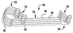
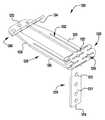
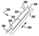
이제 도 32 내지 도 35를 참조하면, 예시적인 바브 클래스프(700, 800, 900, 1000)가 도시되어 있다. 클래스프(400, 500, 600)와 같은, 바브 클래스프(700, 800, 900, 1000)가 상술된 이식가능한 장치(100, 200, 300)에 사용될 수 있다. 그러나, 바브형 클래스프(400, 500, 600)와 달리, 바브형 클래스프(700, 800, 900, 1000)는 상부로부터보다는 클래스프의 측면으로부터의 레이저 절단 재료에 의해 형성된다. 측면으로부터의 레이저 절단은 클래스프 제조에 요구되는 작업을 감소시키고, 각각의 부분의 기능에 기초하여 클래스프의 부분의 굽힘 특성을 변화시키기 위해 클래스프의 두께가 변화되게 한다. 예를 들어, 힌지 부분은 더 많은 가요성을 제공하기 위해 더 얇아질 수 있는 반면, 아암은 더 큰 강성을 제공하기 위해 더 두꺼워질 수 있다.Referring now to FIGS. 32-35, exemplary barb clasps 700, 800, 900, 1000 are shown. Barb clasps 700, 800, 900, 1000, such as
이제 도 32를 참조하면, 적층된 바브 클래스프(700)가 도시된다. 바브 클래스프(700)는 두꺼운 부분(702) 및 얇은 부분(704)을 갖고, 교번하는 스페이서 층(706) 및 바브형 층(708)으로 형성되어 적층 구조를 형성한다. 클래스프(700)는 가동 아암(720), 고정 아암(722), 및 힌지 부분(724)을 포함한다. 가동 아암(720)은 바브형 층(708) 내에 형성된 바브(728)를 갖는 바브형 부분(726)을 포함한다. 측면 프로파일로부터의 레이저 절단에 의해 층(706, 708)을 형성하는 것은 바브(728)가 테이퍼지게 하고, 이에 의해 강성 바브에게 예리한 지점을 제공한다. 고정 아암(722)은 이식가능한 장치에 클래스프(700)를 고정하는 구멍을 포함한다. 이식가능한 장치에 조립될 때, 고정 아암(722)은 부착된 내부 패들에 의해 연장되고, 따라서 자연 조직은 가동 아암(720)과 장치의 내부 패들 사이에서 핀칭된다. 가동 및 고정 아암(720, 722)은 고정 아암(722)의 연장부가 가동 아암(720)과 교차하도록 서로에 대해 각도를 이루어 형성된다. 내부 패들에 고정 아암(722)을 부착하는 것은 내부 패들이 가동 아암(720)과 간섭하도록 고정 아암(722)의 단부를 효과적으로 연장시킨다. 구성요소의 간섭은 클래스프(700)가 개방되도록 가동 아암(720)이 고정 아암(722)에 대해 이동되게 하고, 이에 의해 클래스프(700)가 폐쇄 위치에 있을 때 핀치 힘이 내부 패들에 대해 인가되도록 가동 아암(722)을 예비로딩한다. 따라서, 핀치 힘이 클래스프(700)의 가동 및 고정 아암(720, 722)을 형상 설정하지 않고 가동 및 고정 아암(720, 722) 사이에 생성된다. 대안적으로, 개별 층은 서로 평행한 가동 및 고정 아암(720, 722)이 형성되고, 이어서 클래스프(700)가 내부 패들에 부착될 때 가동 아암(720)이 고정 아암(722)을 향해 편향되도록 굴곡 및 형상 설정된다.Referring now to FIG. 32, a
이제 도 33 내지 도 35를 참조하면, 예시적인 바브 클래스프(800, 900, 1000)가 도시되어 있다. 클래스프(800, 900, 1000)는 전체 형상에서 유사하며, 측면으로부터 클래스프를 레이저 절단할 때 가능한 다양한 두께를 나타낸다. 클래스프(800, 900, 1000)는 얇은 부분(804, 904, 1004) 및 두꺼운 부분(802, 902, 1002)을 갖는다. 클래스프(800, 900, 1000)는 가동 아암(820, 920, 1020), 고정 아암(822, 922, 1022), 힌지 부분(824, 924, 1024)을 포함한다. 가동 아암(820, 920, 1020)은 클래스프(700)의 바브 부분(726)의 바브(728)와 유사한 바브(도시되지 않음)를 갖는 바브 부분(826, 926, 1026)을 포함한다. 도 33 내지 도 35에서 알 수 있는 바와 같이, 클래스프(800, 900, 1000)를 이식가능한 장치에 고정하기 위해 고정 아암(822, 922, 1022) 내에 구멍이 제공될 수 있다. 이식가능한 장치에 조립될 때, 고정 아암(822, 922, 1022)은 부착된 내부 패들에 의해 연장되고, 따라서 자연 조직은 가동 아암(820, 920, 1020)과 장치의 내부 패들 사이에서 핀칭된다.Referring now to FIGS. 33-35, exemplary barb clasps 800, 900, 1000 are shown. The
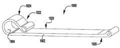
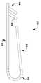
이제 도 36을 참조하면, 바브형 클래스프(400, 500, 600)와 유사한 예시적인 바브형 클래스프(1100)가 도시되어 있다. 그러나, 바브형 클래스프(400, 500, 600)와 달리, 바브형 클래스프(1100)는 두꺼운 부분(1102)과 얇은 부분(1104) 사이에서 두께가 변하는 재료의 단일 층으로 형성된다. 바브형 클래스프(1100)는 고정 아암(1110), 힌지 부분(1120), 및 가동 아암(1130)을 포함한다. 고정 아암(1110)은 부착 구멍(1112) 및 선택적인 통합형 크로스바(1114)를 포함한다. 힌지 부분(1120)는 얇은 부분(1104)으로 형성된 아치형 힌지(1122)를 포함한다. 가동 아암(1130)은 바브(1144)를 갖는 바브형 부분(1140)을 포함한다. 봉합사(도시되지 않음)가 바브형 부분(1140) 부근의 아일릿(1142)에 부착되어 클래스프(1100)를 개방 및 폐쇄할 수 있다.Referring now to FIG. 36, an exemplary
바브형 클래스프(1100)를 형성하기 위해, 재료의 시트가 얇아져 얇은 부분(1104)을 형성한다. 이어서, 클래스프(1100)의 형상이, 힌지 부분(1120)이 얇은 부분(1104)과 정렬되도록, 재료의 시트로부터 레이저 절단된다. 이어서, 바브(1144) 및 고정 아암(1110)은 형상 설정 전에 도 36에 도시된 위치로 굴곡된다. 고정 아암(1110)의 선택적인 T-형상의 크로스바(1114)는 형상 설정을 위해 가동 아암(1130) 내의 슬롯을 통해 삽입하고 그리고 아암(1110, 1130)을 예비로딩 위치로부터 폐쇄 위치로 이동시키기 위해 트위스트되어야 한다. 특정 실시예에서, 선택적인 T-형상의 크로스바(1114)는 생략되고, 더 작거나, 또는 제조 및 형상 설정의 용이성을 용이하게 하기 위해 가동 아암(1130) 내의 릴리프로 대안적으로 대체된다. 형상 설정 후에, 크로스바는 트위스트되고, 슬롯을 통해 다시 이동되고, 두꺼운 부분(1102)의 상부에 위치설정된다. 크로스바(1114)는 크로스바(414)(도 26 참조)와 대체로 동일한 방식으로 위치설정된다.To form the
상술된 클래스프(400, 500)와 마찬가지로, 클래스프(1100)는 폐쇄될 때에 계속 핀칭 힘을 제공하면서 클래스프 재료를 소성 변형시키지 않으면서 완전히 개방될 수 있다. 클래스프(1100)가 단일 재료의 시트로부터 절단되고 재료의 층을 함께 용접하기 위해 용접 단계가 필요하지 않기 때문에, 전술된 클래스프에 비해 클래스프(1100)를 제조하기 위해 더 적은 단계가 요구된다.Like the
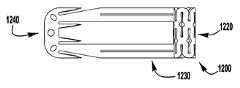
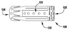
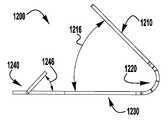
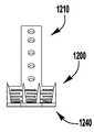
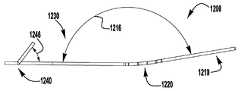
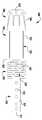
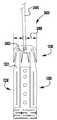
이제 도 37 내지 도 52를 참조하면, 상술된 장치(100, 200, 300)와 같은, 이식가능한 인공 장치에 사용하기 위한 예시적인 바브형 클래스프(1200)가 도시된다. 바브형 클래스프(1200)는 재료의 단일 층(1202)으로 형성된다. 바브형 클래스프(1200)는 고정 아암(1210), 힌지형 부분(1220), 및 바브형 부분(1240)을 갖는 가동 아암(1230)을 포함한다. 힌지형 부분(1220)은 고정 및 가동 아암(1210, 1230)이 바브형 클래스프(1200)가 폐쇄 상태에 있을 때 서로를 향해 편향되도록 스프링-로딩된다. 이식가능한 인공 장치에 조립될 때, 고정 아암(1210)은 인공 장치의 일부에 부착된다. 클래스프(1200)는 힌지 부분(1220)의 스프링력이 극복될 때까지 가동 아암(1230)에 부착된 작동 라인 또는 봉합사와 같은 작동 수단을 당김으로써 개방된다.Referring now to FIGS. 37-52, an exemplary
고정 아암(1210)은 가동 아암(1230)의 2개의 측면 빔(1231) 사이의 힌지형 부분(1220)으로부터 단부(1214)까지 연장되는 재료의 설부(1211)로 형성된다. 일부 실시예에서, 가동 아암은 고정 아암의 2개의 측면 빔 사이에서 연장되는 재료의 설부로 형성된다. 도 39 내지 도 40e에서 알 수 있는 바와 같이, 설부(1211)는 힘이 측면 빔(1231)을 넘어 위치되는 중립 위치로부터 측면 빔(1231)과 거의 평행하거나 또는 평행한 예비로딩된 위치로 설부(1211)를 이동시키기 위해 인가되어야 하도록 힌지 부분(1220)에 의해 측면 빔(1231) 사이에서 편향된다. 설부(1211)는 설부가 이식가능한 인공 장치의 패들에 부착될 때 예비로딩된 위치에 유지된다. 설부(1211)의 단부(1214)는 설부(1211)를 예비로딩된 위치에 유지하기 위해 측면 빔(1231)과 결합하는 T-형상의 크로스 부재를 선택적으로 가질 수 있다.The fixed
특정 실시예에서, 설부(1211)가 중립 위치에 있을 때 고정 및 가동 아암(1210, 1230) 사이의 각도는 약 30 내지 약 120도, 40 내지 약 110도, 또는 약 50 내지 약 100도, 또는 약 60 내지 약 90도, 또는 약 90도이다. 설부(1211)는 이식가능한 장치에 고정 아암(1210)을 부착하는 봉합사(도시되지 않음)를 수용하기 위한 구멍(1212)을 포함한다.In certain embodiments, the angle between the stationary and
힌지 부분(1220)은 고정 아암(1210)의 설부(1211)로부터 가동 아암(1230)의 측면 빔(1231)으로 연장되는 반복 패턴으로 배열된 복수의 비틀림 스프링 세그먼트(1222)에 의해 형성된다. 각각의 스프링 세그먼트(1222)는 다른 스프링 세그먼트(1222)와 결합되어 반복 패턴을 형성한다. 다수의 세그먼트(1222)를 함께 결합하는 것은 개별 비틀림 스프링 세그먼트(1222)가 트위스트될 때 재료의 소성 변형을 피하면서 힌지 부분(1220)이 상당한 양으로 굴곡되게 한다. 예를 들어, 특정 실시예에서, 설부(1211)는 클래스프 재료를 소성 변형시키지 않고 가동 아암(1230)으로부터 약 140도 내지 약 200도, 약 170도 내지 약 190도, 또는 약 180도 범위의 완전 개방 위치로 가동 아암(1230)을 넘어 대략 90도인 중립 위치로부터 피봇될 수 있다. 특정 실시예에서, 클래스프 재료는 폐쇄 위치에서 고정 및 가동 아암 사이에 가해지는 핀치 힘을 감소시키거나 실질적으로 감소시키지 않으면서 개방 중에 소성 변형될 수 있다. 패턴 스프링 세그먼트(1222)는 힌지 부분(1220) 내의 개방 및 폐쇄 절결부(1224)로 형성된다. 예시적인 스프링 세그먼트 및 이들의 패턴의 배열이 이하에서 설명되고 도 51a 내지 도 52에 도시된다.
설부(1211)를 예비로딩하는 것은 클래스프(1200)가 폐쇄될 때 자연 판막첨 상에 핀칭 또는 클립핑 힘을 유지할 수 있게 하고 또한 자연 판막첨을 더 쉽게 포획하기 위해 넓게 개방될 수 있게 한다. 설부(1211)의 예비로딩은 폐쇄될 때 핀칭 힘을 거의 또는 전혀 제공하지 않는 종래 기술의 클립에 비해 상당한 장점을 제공한다. 추가적으로, 클래스프(1200)는 폐쇄될 때 충분한 핀칭 힘을 계속 유지하면서, 판막첨 상의 재배치를 위해서 반복적으로 개방 및 폐쇄될 수 있기 때문에, 클래스프(1200)를 스프링력으로 폐쇄하는 것은 1회 로킹 폐쇄 기구를 이용하는 클립에 비해 상당한 개선이다.
가동 아암(1230)의 바브형 부분(1240)은 아일릿(1242) 및 바브(1244)를 포함한다. 클래스프(1200)가 개방될 때 클래스프(1200)의 바브형 부분을 가동 아암(1230)의 단부에 위치설정하는 것은 바브(1244)와 고정 아암(1210) 사이의 공간을 증가시키고, 이에 의해 클래스프(1200)가 이식 중에 판막첨을 성공적으로 포획하는 능력을 향상시킨다. 이 거리는 또한 바브(1244)가 재배치를 위해 판막첨으로부터 더 신뢰성 있게 분리될 수 있게 한다. 특정 실시예에서, 클래스프의 바브는 핀치 힘 및 국부적 판막첨 응력을 더 분배하도록 종방향으로 엇갈릴 수 있다. 특정 실시예에서, 바브(1244)의 단부는 임의의 적절한 연마 수단을 사용하여 더 예리해진다.
바브(1244)는 힌지 부분(1220)으로부터 동일한 거리 측방향으로 이격되어 있고, 이는 또한 클래스프가 종방향 로우로 배열된 바브보다 판막첨 포획에 대해 더 강건하게 만들면서, 판막첨 조직에 대한 우수한 핀칭 힘의 분배를 제공한다. 일부 실시예에서, 바브(1244)는 핀치 힘 및 국부적 판막첨 응력을 더 분배하도록 엇갈릴 수 있다.The
바브(1244)는, 이들이 최소 핀칭 또는 클립핑 힘으로 자연 판막첨의 조직과 용이하게 결합하도록, 각도(1246)를 이루어 가동 아암(1230)으로부터 멀리 경사진다(도 38a). 사용 중에, 클래스프(1200)가 판막첨을 확실하게 파지하는데 조직의 침투가 필요하지는 않지만, 바브(1244)는 자연 판막첨 조직에 침투할 수 있다. 바브(1244)는 약 20도 내지 약 90도, 또는 약 40도 내지 약 70도, 또는 약 50도 내지 약 60도, 또는 약 53도의 각도(1246)로 가동 아암으로부터 연장된다. 바브(1244)의 각도는, 임플란트를 자연 판막첨으로부터 당기는 힘이 바브(1244)가 조직과 더 결합하여 더 양호한 보유를 보장하는 것을 촉진한다는 점에서, 추가의 이점을 제공한다. 클래스프(1200) 내의 판막첨의 보유는 클래스프(1200)가 폐쇄될 때 고정 아암(1210)의 단부(1214)의 위치에 의해 더 개선된다. 이러한 배열에서, 바브(1244)에 의해 결합된 조직이 단부(1214) 위치에서 가동 아암(1230)에 대해서 핀칭되고, 이에 의해 조직을 바브(1244) 위를 통과할 때 S-형상의 구불구불한 경로 내로 형성한다. 따라서, 판막첨을 클래스프(1200)로부터 멀리 당기는 힘은, 판막첨이 빠져나갈 수 있기 전에, 조직이 바브(1244)와 더 결합하는 것을 촉진할 것이다. 단부(1214)는 고정 및 가동 아암(1210, 1230) 사이에 포획된 조직의 구불구불한 경로의 S-형상을 강조하기 위해 가동 아암(1230)을 향해 약간 굴곡된 상태로 선택적으로 형상 설정될 수 있다.The
클래스프(1200)의 재료의 층(1202)은 니티놀과 같은, 형상 기억 합금의 시트로부터 레이저 절단된다. 고정 아암(1210), 힌지 부분(1220) 및 바브(1244)와 같은, 층(1202)의 부분은 원하는 위치로 굴곡된다. 이어서, 클래스프(1200)가 형상 설정 프로세스를 거쳐서, 재료의 내력이 외력에 의해서 변형된 후에 설정 형상으로 복귀되는 경향이 있을 것이다. 형상 설정 후에, 설부(1211)는 이식가능한 장치에 부착되도록 그 예비로딩, 폐쇄 또는 개방 위치로 이동된다. 결과적으로, 클래스프(1200)는 전달 외피를 통한 전달을 위해 폐쇄 위치에서 실질적으로 평탄화되고, 일단 심장 내에서 전개되면 확장되도록 허용될 수 있다.
클래스프(1200)는 가동 아암(1230)에 부착된 작동 라인 또는 봉합사(예컨대, 도 71의 봉합사(2504))에 장력을 인가 및 해제함으로써 개방 및 폐쇄된다. 봉합사는 전달 외피로 복귀하기 전에 가동 아암(1230)의 바브형 부분(1240) 부근에 위치된 아일릿(1242) 중 적어도 하나를 통해 삽입된다. 특정 실시예에서, 중간 봉합사 루프는 아일릿(1242) 중 하나 이상을 통해 형성되고, 작동 봉합사는 중간 루프 중 하나 이상을 통해 삽입된다. 봉합사 재료의 중간 루프는 작동 봉합사와 클래스프 재료 사이의 마찰에 대해 작동 봉합사가 겪는 마찰을 감소시킨다. 봉합사가 아일릿(1242) 또는 중간 루프를 통해 루프 형성될 때, 작동 봉합사의 양 단부는 전달 외피(102) 내로 그리고 그를 통해 다시 연장된다(예컨대, 도 1 참조). 봉합사는 봉합사의 다른 단부가 아일릿 또는 중간 루프를 통해 그리고 전달 외피 내로 다시 당겨질 때까지 봉합사의 일 단부를 근위방향으로 당김으로써 제거될 수 있다.The
전술된 클래스프(400, 500)와 마찬가지로, 클래스프(1200)는 폐쇄될 때에 계속 핀칭 힘을 제공하면서 클래스프 재료를 소성 변형시키지 않으면서 완전히 개방될 수 있다. 클래스프(1200)가 단일 재료의 시트로부터 절단되고 재료의 층을 함께 용접하기 위해 용접 단계가 필요하지 않기 때문에, 전술된 클래스프에 비해 클래스프(1100)를 제조하기 위해 더 적은 단계가 요구된다.Like the
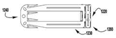
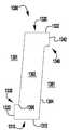
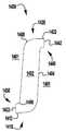
이제 도 37 내지 도 48e를 참조하면, 클래스프(1200)는 중립 위치(도 37 내지 도 38e)로부터 완전 개방 위치(도 47 내지 도 48e)까지 범위의 다양한 굴곡 위치로 도시되어 있다. 고정 아암(1210)이 도 37 내지 도 48e의 상이한 위치로 도시되어 있지만, 일단 이식가능한 장치에 설치되면, 고정 아암(1210)이 장치에 대해 고정된 상태로 유지되면서 가동 아암(1230)은 장치에 대해 이동하도록 외과 의사에 의해 작동된다.Referring now to FIGS. 37-48E,
도 37 내지 도 38e는 형상 설정을 위해 중립 위치에서의 클래스프(1200)를 도시한다. 형상 설정 중에, 고정 아암(1210)의 설부(1211)는 가동 아암(1230)의 측면 빔(1231) 아래 약 60도 내지 약 120도, 또는 약 90도인 설부 각도(1216)로 굴곡된다. 형상 설정 후에, 설부(1211)는 설부(1211)를 다른 위치로 이동시키는 힘에 의해 작용되지 않으면 형상 설정 또는 중립 위치로 유지된다. 따라서, 설부(1211)가 예비로딩 또는 폐쇄 위치(도 39 내지 도 40e)로 이동될 때, 클래스프 재료의 내력이 폐쇄 방향으로 가해지고, 이에 의해 클래스프(1200)가 폐쇄 또는 예비로딩된 상태에 있을 때 핀칭 힘을 발생시킨다. 클래스프(1200)를 포함하는 의료 장치의 이식 중에, 가동 아암(1230)은 고정 및 가동 아암(1210, 1230) 사이의 각도(1216)를 변경하기 위해 봉합사(도시되지 않음)로 작동된다. 클래스프(1200)는 도 41 내지 도 42e의 1/4 개방 상태, 도 43 내지 도 44e의 절반 개방 상태, 도 45 내지 도 46e의 3/4 개방 상태, 및 도 47 내지 도 48e의 완전 개방 상태로 도시되어 있다. 완전 개방 위치에서 고정 및 가동 아암(1210, 1230) 사이의 각도(1216)는 약 140도 내지 약 200도, 약 170도 내지 약 190도, 또는 약 180도일 수도 있다. 즉, 클래스프(1200)는 클래스프 재료의 소성 변형 없이 실질적으로 완전히 편평하게 개방될 수 있다.37-
이제 도 49 및 도 50을 참조하면, 클래스프(1200)를 형성하기 위한 재료의 층(1202)은 예비 형상 설정 상태, 즉 재료의 시트로부터 레이저 절단된 후 실질적으로 편평한 상태로 도시된다. 도 50은 특히 힌지 부분(1220)를 형성하는 스프링 세그먼트(1222) 및 절결부(1224)의 패턴의 반복 특성을 명확하게 도시한다.Referring now to FIGS. 49 and 50, the
이제 도 51a 내지 도 51d를 참조하면, 패턴화된 힌지 부분(예컨대, 클래스프(1200)의 힌지 부분(1220))에 대한 예시적인 비틀림 스프링 세그먼트(1300, 1400, 1500, 1600)가 도시되어 있다. 스프링 세그먼트(1300, 1400, 1500, 1600)는 개별 세그먼트 사이에 물리적 시임이 없도록 단일 편으로 절단되는 반복 패턴으로 배열 가능하다. 따라서, 스프링 세그먼트(1300, 1400, 1500, 1600)의 형상은 힌지 부분 내의 절결부 및 세그먼트 사이의 "조인트"에서의 가상 경계에 의해 형성된다.Referring now to FIGS. 51A-51D, exemplary
이제 도 51a를 참조하면, 스프링 세그먼트(1300)는 실질적으로 회전 대칭인 S형 형상을 초래하는 재료의 층(1302) 내에 만들어진 절결부(1301)에 의해 형성된다. 각각의 스프링 세그먼트(1300)는 제1 단부(1310)로부터 제1 측면(1330)과 제2 측면(1340) 사이의 제2 단부(1320)로 연장된다. 제1 단부 결합 위치(1312)는 제1 측면(1330)에 인접한 제1 단부(1310)에 위치된다. 제1 측면 결합 위치(1332)는 제1 단부(1310)에 인접한 제1 측면(1330)에 위치된다. 제2 단부 결합 위치(1322)는 제2 측면(1340)에 인접한 제2 단부(1320)에 위치된다. 제2 측면 결합 위치(1342)는 제2 단부(1320)에 인접한 제2 측면(1340)에 위치된다. 측면(1304)은 제1 단부 결합 위치(1312)와 제2 측면 결합 위치(1342) 사이에서, 그리고 제2 단부 결합 위치(1322)와 제1 측면 결합 위치(1332) 사이에서 연장된다. 내부 코너(1306)가 각각의 측면 결합 위치(1332, 1342) 부근에 형성된다.Referring now to FIG. 51A,
이제 도 51b 내지 도 51d를 참조하면, 스프링 세그먼트(1400, 1500, 1600)가 도시되어 있다. 이러한 스프링 세그먼트(1400, 1500, 1600)는 상술된 스프링 세그먼트(1300)와 구조가 유사하지만, 스프링 세그먼트(1400, 1500, 1600)는 측면 결합 위치에 대향하는 각각의 단부 결합 위치 근처에서 외부 코너(1408, 1508, 1608)를 포함한다. 스프링 세그먼트(1300, 1400, 1500, 1600)의 형상은 측면(1304, 1404, 1504, 1604), 라운딩된 내부 코너(1306, 1406, 1506, 1606) 및 라운딩된 외부 코너(1408, 1508, 1608)의 크기 및 형상으로 변한다. 예를 들어, 측면(1304, 1404)은 실질적으로 직선인 반면, 측면(1504, 1604)은 오목하다. 이러한 형상의 차이는 상이한 형상의 스프링 세그먼트의 패턴으로 형성된 힌지 부분에서의 응력 분포를 변화시킨다.Referring now to FIGS. 51B-51D,
이제 도 52를 참조하면, 스프링 세그먼트(1300)의 예시적인 스프링 그룹화(1700)가 도시되어 있다. 도 52에서 알 수 있는 바와 같이, 측면 결합 위치(1332, 1342)는 다른 측면 결합 위치(1332, 1342)에 결합되고, 단부 결합 위치(1312, 1322)는 다른 단부 결합 위치(1312, 1322)에 결합된다. 스프링 세그먼트(1300)의 실질적으로 회전 대칭인 형상은 하나의 세그먼트의 단부(1310, 1320) 또는 측면(1330, 1340)이 다른 세그먼트의 단부(1310, 1320) 또는 측면(1330, 1340)에 접합되게 한다. 이어서, 도 52의 그룹화(1700)에 의해 형성된 H-패턴과 같은, 다양한 패턴이 형성될 수 있다. 세그먼트(1300, 1400, 1500, 1600)가 실질적으로 회전 대칭인 동안, 세그먼트의 패턴 내의 개별 세그먼트는 힌지 부분의 라운딩된 외부 연부를 형성하거나 또는 클래스프의 고정 또는 가동 아암에 적응하도록 변형될 수 있다.Referring now to FIG. 52, an
스프링 그룹화(1700)가 굽힘력(1710)을 받을 때, 각각의 세그먼트(1300)는 화살표(1720)로 표시된 방향으로 트위스트된다. 결과적으로, 개별 스프링 세그먼트(1300)는 비틀림 변형을 받고 굽힘 변형을 받지 않는다. 또한, 클래스프의 힌지 부분의 스프링력을 유지하면서 유사한 방식으로 굴곡되는 재료의 평탄한 시트의 굽힘에 대해 재료(1302)의 변형이 감소되는 것을 알 수 있다. 결과적으로, 비틀림 스프링 세그먼트의 패턴으로 형성된 힌지 부분은 강하고 가요성이다.When
상술된 힌지 부분(1220)과 같은, 패턴화된 힌지 부분을 형성하기 위해, 복수의 스프링 세그먼트를 포함하는 패턴이 로우 및 컬럼으로 배열된다. 도 49, 도 50 및 도 52에서 알 수 있는 바와 같이, 스프링 세그먼트는 동일한 배향으로 그 종방향 및 측방향 축을 갖도록 배열된다. 특정 실시예에서, 스프링 세그먼트는 서로에 대해 회전되어 상이한 스프링 패턴을 형성할 수 있다. 스프링 세그먼트는 컬럼 및 로우로 구성된다. 컬럼은 클래스프의 종축을 따라 형성되고, 로우는 클래스프의 측방향 축을 따라 형성된다. 따라서, 스프링 세그먼트의 컬럼은 개별 스프링 세그먼트의 최장 치수만큼 넓은 반면, 스프링 세그먼트의 로우는 개별 스프링 세그먼트의 최단 치수와 동일한 높이를 갖는다. 예를 들어, 도 50에 도시된 클래스프(1200)는 (힌지 부분을 고정 및 가동 아암에 연결하는 부분 로우를 포함하지 않는) 3개의 컬럼 및 7개의 로우의 스프링 세그먼트를 포함한다. 세그먼트의 단부가 클래스프의 연부와 경계를 이루는 경우, 인접한 로우 내의 2개의 세그먼트는 하나의 위치에서 함께 결합되어 U-형상의 그룹화를 형성한다. 스프링 세그먼트의 개별 스프링 세그먼트 또는 그룹화는 힌지 부분의 연부의 평활성 및/또는 견고성을 증가시키기 위해 그 회전 대칭으로부터 멀리 변형될 수 있다. 세그먼트의 단부가 2개의 컬럼의 교차부에 위치되는 경우, 세그먼트는 도 62에 도시된 그룹화(1700)와 같이, X-형상의 그룹화를 형성하는, 3개의 다른 세그먼트에 결합될 수 있다. 패턴화된 힌지는 임의의 적절한 개수의 스프링 세그먼트의 로우 및 컬럼을 포함할 수 있다. 각각의 세그먼트의 크기 및 형상은 패턴화된 힌지의 스프링 파라미터를 조정하도록 조정될 수 있다. 스프링 세그먼트의 크기 및 형상은 패턴화된 힌지 전반에 걸쳐 균일할 수 있거나, 또는 패턴 내의 스프링 세그먼트의 위치에 기초하여 변할 수 있다.To form a patterned hinge portion, such as the
이제 도 53 내지 도 55를 참조하면, 4-축 레이저 절단(X, Y, Z, 및 회전 축) 및 5-축 레이저 절단(X, Y, Z, 및 레이저 헤드에 대한 2개의 경사 축)을 사용하여 재료의 튜브(1802)로부터 절단되는 예시적인 바브 클래스프(1800)가 도시되어 있다. 튜브는 먼저 세그먼트로 절단될 수 있고, 이어서 각각의 세그먼트는 평평한 스톡편 또는 블랭크 재료가 절단되는 것과 대체로 동일한 방식으로 절단되고, 즉 튜브는 편평한 블랭크 대신 만곡된 블랭크를 제공한다. 레이저 커터의 추가의 자유도는 레이저 절단 중에 튜브가 회전되거나 레이저 커터의 헤드가 기울어지게 한다. 튜브를 회전시키거나 레이저 절단 헤드를 기울이는 것은 별도의 연마 작업을 필요로 하지 않고도 도 55에 도시된 더 예리한 바브 구성으로 바브가 절단될 수 있게 한다. 클래스프(1800)는 위에서 상세히 설명된 클래스프(1200)와 구조가 유사하다. 재료의 튜브(802)는 내부 반경(1804), 내부 표면(1801), 및 외부 표면(1803)을 갖는다. 재료의 튜브(1802)로부터 클래스프(1800)를 절단하는 것은, 도 54에 도시된 바와 같이, 단부로부터 볼 때 컵형 또는 오목한 프로파일을 제공한다. 오목한 프로파일의 하나의 효과는, 힌지 부분(1820)의 가요성에 실질적으로 영향을 주지 않고, 고정 및 이동 아암(1810, 1830)의 세장형 부분이 그 강성을 증가시킨다는 것이다. 오목한 프로파일은 또한 별도의 연마 작업 없이 더 예리한 지점 또는 팁(1846)을 갖는 바브(1844)를 초래하고, 즉 바브에는 연마 없이 경사형 연부가 형성된다. 예리한 지점(1846)은 자연 판막첨 조직과의 개선된 결합을 가능하게 한다. 도 55를 참조하면, 팁(1846)에서 교차하는 바브(1844)의 제1 및 제2 측면(1847, 1848)을 형성하는 절단 평면이, 바브의 측면을 형성하는 절단 평면이 평행하고 교차하지 않는 경우에 가능하지 않은 지점으로 되는 삼각 피라미드 형상을 형성하기 때문에, 예리한 지점(1846)은 레이저 절단 중에 형성된다. 따라서, 클래스프(1800)의 바브(1844)는 어떠한 2차 연마 작업 없이 단일 층의 재료 내에 강한 기부(1845) 및 예리한 지점(1846)을 갖는다.Referring now to FIGS. 53-55, four-axis laser cutting (X, Y, Z, and rotational axes) and five-axis laser cutting (X, Y, Z, and two tilt axes for the laser head) An
이제 도 56을 참조하면, 예시적인 클래스프(1900)가 도시되어 있다. 클래스프(1900)는 상이하게 구조화된 힌지 부분(1920)을 갖고 위에서 상세히 설명된, 클래스프(1200)와 유사한 구조이다. 힌지 부분(1920)은 일련의 세장형 절결부(1924)에 의해 형성된 복수의 빔(1922)을 포함한다. 이제 도 56a 및 도 56b를 참조하면, 힌지 부분(1920)의 빔(1922)의 대안적인 실시예가 도시되어 있다. 도 56a는 굽힘 부분(1926)를 갖는 직사각형 빔(1922)을 도시한다. 도 56b는 굽힘 부분(1926)의 빔의 단면이 그 단부에서 빔(1922)의 부분에 수직하도록 또한 약 90도 트위스트된 굽힘 부분(1926)을 갖는 직사각형 빔(1922)을 도시한다. 빔(1922)을 트위스팅함으로써, 도 56b에 도시된 바와 같이, 빔(1922) 내의 굽힘 변형을 감소시키고, 이에 의해 가요성을 증가시킨다.Referring now to FIG. 56, an
이제 도 57 및 도 58을 참조하면, 상술된 장치(100, 200, 300)와 같은, 이식가능한 인공 장치에 사용하기 위한 예시적인 바브형 클래스프(2000)가 도시된다. 바브형 클래스프(2000)는 이식가능한 장치에 부착된 고정 아암(2010)을 포함한다. 바브형 클래스프(2000)는 클래스프(2000)가 힌지형 부분(2020) 및 단일 바브(2042)를 갖는 바브형 부분(2040)을 각각 갖는 복수의 가동 아암(2030)을 포함한다는 점에서 다른 클래스프와 상이하다. 클래스프(2000)의 독립적인 아암(2030)은 두께가 균일하지 않은 조직의 개선된 결합을 허용하는 자연 판막첨의 조직을 개별적으로 핀치한다. 아암(2030)은 또한 넓게 또는 확산된 배열로 형상 설정될 수 있고, 바브(2042)가 아암이 견고하게 연결되는 경우 가능한 것보다 더 측방향으로 이격될 수 있도록 전개를 위해 좁은 구성으로 크림핑될 수 있다. 특정 실시예에서, 아암(2030)은 전개 중에 아암(2030)을 함께 매어 두기 위해 작동 봉합사에 의해 결합될 수 있는 선택적 구멍 또는 노치(도시되지 않음)를 포함한다.Referring now to FIGS. 57 and 58, an exemplary
고정 아암(2010)은 가동 아암(2030)을 형성하는 빔(2031)이 연장되는 설부(2011)로 형성된다. 힌지 부분(2020)은 각각의 빔(2031)을 굴곡시켜 굽힘 부분(2022)를 형성함으로써 형성된다. 힌지형 부분(2020)은 고정 및 가동 아암(2010, 2030)이 바브형 클래스프(2000)가 폐쇄 상태에 있을 때 서로를 향해 편향되도록 스프링-로딩된다. 특정 실시예에서, 설부(2011)는 독립적인 아암(2030)을 위한 핀칭 위치로서 더 큰 측방향 영역을 제공하도록 넓은 플레이트의 재료로 형성된다.The fixed
바브형 클래스프(2000)는 니티놀과 같은, 형상 기억 합금의 층(2002)으로부터 레이저 절단된다. 도 57a에 도시된 바와 같이, 바브(2042)는 재료의 층(2002)으로 절단될 때 클래스프(2000)의 나머지와 동일한 평면에서 편평하게 놓인다. 이어서, 가동 아암(2030) 및 바브(2040)가 굴곡되고 도 57에 도시된 형상으로 트위스트되고 이어서 형상 설정 프로세스를 거친다. 전술된 바와 같이, 클래스프(2000)의 독립 아암(2030)은 원하는 대로 넓거나 좁게 형상 설정될 수 있다. 특정 실시예에서, 개별 아암(2030)은 다른 것보다 더 길거나 짧을 수 있고, 아암(2030)의 간격은 변하거나 또는 균일할 수 있다.The
재료의 시트로부터 바브(2042)를 절단한 후에 그들을 위치로 트위스팅하는 것은 또한 다양한 형상의 더 큰 바브가 형성되게 한다. 특정 실시예에서, 바브형 부분(2040)은 동일한 방향으로 대면하거나 그렇지 않을 수 있는 직렬로 배열된 다수의 작은 바브를 포함할 수 있다. 특정 실시예에서, 바브(2042)의 단부는 임의의 적절한 연마 수단을 사용하여 더 예리해진다. 특정 실시예에서, 빔(2031)의 힌지 부분(2020)은 트위스트된 부분(2024)을 포함한다. 트위스트된 부분(2024)은 바브(2042)의 단부에 인가된 측방향 힘에 저항하는 비틀림 스프링으로서 작용할 수 있고, 이에 의해서 자연 판막첨의 조직과 결합될 때 바브(2042)의 정렬을 유지하는 것을 돕는다.Twisting them into position after cutting the
이제 도 59 내지 도 63을 참조하면, 상술된 장치(100, 200, 300)와 같은 이식가능한 인공 장치에 사용하기 위한 예시적인 클래스프(2100)가 도시된다. 클래스프(2100)는 접힌 상태와 확장된 상태 사이에서 확장되고, 클래스프(2100)가 접힌 상태로부터 확장된 상태로 자동으로 확장되도록 확장된 상태에서 형상 설정된다. 도 61a에서 알 수 있는 바와 같이, 클래스프(2100)는 접힌 상태의 전달 외피(2150)로부터 전개될 수 있고 확장된 상태로 자가 확장되게 할 수 있다.Referring now to FIGS. 59-63, an
클래스프(2100)는, 위에서 상세하게 설명된 클래스프(1200)와 유사한 많은 특징부, 예를 들어 복수의 스프링 세그먼트(2122) 및 절결부(2124)에 의해 형성된 패턴화된 힌지 부분(2120) 및 고정 아암(2110)을 가지며, 고정 아암(2110)은 고정 아암(2110)을 이식가능한 장치에 부착하기 위한 구멍(2112)을 갖는 설부(2111) 및 고정 아암(2110)을 예비로딩된 위치에서 유지하기 위한 T-형상을 갖는 단부(2114)를 포함한다. 클래스프(2100)는 또한 복수의 바브(2142)를 갖는 바브형 부분(2140)을 포함하는 가동 아암(2130)을 갖는다.The
가동 아암(2130)의 후프형 형상은 다른 클래스프보다 동일하거나 더 큰 측방향 간격을 갖는 더 많은 바브(2142)를 포함할 수 있는 더 넓은 바브형 부분(2140)을 제공한다. 바브(2142)의 더 넓은 간격은 자연 판막첨의 포획을 개선한다. 특정 실시예에서, 가동 아암(2130)의 후프 형상은 패들의 핀칭 힘이 바브 상에 균등하게 확산되도록 이식가능한 장치의 넓은 외부 패들의 형상과 유사하고, 자연 판막첨의 보유를 더 향상시킨다. 바브(2142)의 일부는 또한 가동 아암(2130)의 후프형 형상 상의 그 위치의 결과로서 종방향으로 엇갈릴 수 있다. 특정 실시예에서, 바브(2042)의 단부는 임의의 적절한 연마 수단을 사용하여 더 예리해진다. 특정 실시예에서, 설부(2111)는 핀칭 위치로서 더 큰 측방향 영역을 제공하기 위해 넓은 플레이트의 재료로 형성된다.The hoop shape of the
가동 아암(2130)은 후프 또는 루프의 형상으로 제공된다. 가동 아암(2130)은 상술된 클래스프(1200)의 측면 빔(1231)보다, 특히 측방향으로 더 얇고 더 가요성인 측면 빔(2131)을 포함한다. 측면 빔(2131)은 가동 아암(2130)의 근위 단부를 향해 배열된 제1 힌지 부분(2132) 및 가동 아암(2130)의 원위 단부에 배열된 제2 힌지 부분(2136)을 포함한다. 제1 힌지 부분(2132)은 측면 빔(2132)의 하나 이상의 굴곡부에 의해 형성된다. 특정 실시예에서, 제2 힌지 부분(2136)은 클래스프(2100)를 접히게 하기 위해 요구되는 힘을 감소시키기 위해 더 얇고 따라서 더 가요성인 부분을 포함한다. 가동 아암(2130)은 가동 아암(2130)을 접히게 하기 위해 사용되는 작동 봉합사(2152)를 수용하기 위해 제1 및 제2 힌지 부분(2132, 2136) 사이에 배열된 구멍(2134)을 포함한다. 구멍(2134)은 힘이 봉합사(2152)를 통해 인가될 때 기계적 이점을 제공하도록 힌지 부분(2132, 2136)보다 클래스프(2130)의 중심으로부터 더 측방으로 배열된다. 특정 실시예에서, 구멍(2134)은 측면 빔(2131)의 최측방향 위치에 위치된다.The
클래스프(2100)의 라운딩된 후프 형상은 클래스프(2100)가 단지 클래스프(2100)를 전달 외피로 후퇴시킴으로써 접히게 될 수 있게 한다. 특정 실시예에서, 클래스프(2100)의 확장 및 수축은 작동 봉합사(2152)에 의해 제어된다. 봉합사(2152)는, 봉합사(2152)를 따라 인가되는 힘이 가동 아암(2130)을 접힌 위치에 매어 두기 인가되는 방향을 제어하기 위해 가동 아암(2130) 내의 구멍(2134)에 안내부(2154)의 개구부(2156)를 통해 라우팅될 수 있다. 예를 들어, 클래스프(2100)로의 봉합사(2152)에 대한 연결 지점에 더 가까이 안내부(2154)를 배열하는 것은 봉합사(2152)에 의해 클래스프(2100)에 인가되는 힘이 종 방향보다는 더 측방향으로 지향되게 한다. 대안적으로, 도 61b에서 알 수 있는 바와 같이, 단일 봉합사 루프(2153)는 안내부(2154)의 개구부(2156)을 통해, 가동 아암(2130) 내의 각각의 구멍(2134)을 통해, 그리고 이어서 안내부(2154)를 통해 다시 라우팅될 수 있고, 그에 따라 단일 루프(2153)의 작동이 가동 아암(2130)을 접힌 위치에 매어 둘 수 있다.The rounded hoop shape of the
이제 도 64 내지 도 68을 참조하면, 상술된 장치(100, 200, 300)와 같은, 이식가능한 인공 장치에 사용하기 위한 예시적인 바브형 클래스프(2200)가 도시된다. 바브형 클래스프(2200)는 상술된 클래스프(1200, 2000)의 요소를 포함한다. 바브형 클래스프(2200)는 이식가능한 장치에 부착된 고정 아암(2210) 및 클래스프(2200)가 개방 및 폐쇄되게 하는 힌지 부분(2220)을 포함한다. 힌지 부분(2220)은 클래스프(1200)의 반복 패턴과 마찬가지로, 스프링 세그먼트(2222) 및 절결부(2224)의 반복 패턴으로 형성된다.Referring now to FIGS. 64-68, an exemplary
바브형 클래스프(2200)는 또한 단일 바브(2244)를 갖는 바브형 부분(2240)을 각각 갖는 복수의 독립적인 가동 아암(2230)과 같은, 클래스프(2000)와 유사한 특징부를 포함한다. 클래스프(2200)의 독립적인 아암(2230)은 두께가 균일하지 않은 조직의 개선된 결합을 허용하는 자연 판막첨의 조직을 개별적으로 핀치한다. 아암(2230)은 또한 넓게 또는 펼쳐진 배열로 형상 설정될 수 있고, 바브(2244)가 아암이 견고하게 연결되는 경우 가능한 것보다 더 측방향으로 이격될 수 있도록 전개를 위해 좁은 구성으로 크림핑될 수 있다. 각각의 아암(2230)의 바브형 부분(2240)은 작동 봉합사(2252)(도 65a)를 수용하기 위한 구멍(2242)을 포함한다.The
클래스프(2200)는 접힌 상태와 확장된 상태 사이에서 확장 가능하고, 클래스프(2200)가 접힌 상태로부터 확장된 상태로 자동으로 확장되도록 확장된 상태로 형상 설정된다. 도 65a에서 알 수 있는 바와 같이, 클래스프(2200)는 접힌 상태의 전달 외피(2250)로부터 전개될 수 있고 확장된 상태로 자가 확장되게 할 수 있다. 클래스프(2200)의 확장 및 수축은 전달 외피(2250) 내에 끼워지도록 클래스프(2200)를 접히게 하기 위해 독립적인 아암(2230)을 함께 매어 두는 작동 봉합사(2252)에 의해 제어된다. 일부 실시예에서, 독립적인 아암은 전달 외피 내로 클래스프(2100)를 단지 후퇴시킴으로써 함께 접힌다.The
고정 아암(2210)은 힌지 부분(2220)으로부터 단부(2214)로 연장되는 설부(2211)로 형성된다. 설부(2211)는 이식가능한 장치에 설부(2211)를 고정하기 위한 구멍(2212)을 포함한다. 특정 실시예에서, 설부(2211)는 핀칭 위치로서 더 큰 측방향 영역을 제공하기 위해 넓은 플레이트의 재료로 형성된다. 특정 실시예에서, 설부(2211)의 단부(2214)는 클래스프(2100)의 것과 같은 T-형상의 크로스 부재를 포함한다.
바브형 클래스프(2200)는 니티놀과 같은, 형상 기억 합금의 층(2202)으로부터 레이저 절단된다. 도 57a에 도시된 클래스프(2100)와 같이, 바브(2242)는 재료의 층(2202)으로 절단될 때 클래스프(2200)의 나머지와 동일한 평면에서 편평하게 놓인다. 이어서, 가동 아암(2230) 및 바브형 부분(2240)은 도 64 내지 도 68에 도시된 형상으로 굴곡되고 트위스트되고, 이어서 형상 설정 프로세스를 거친다. 일부 실시예에서, 독립적인 아암의 바브는 바브가 클래스프(1200)의 바브와 같이 상향으로 굴곡되도록 절단되고, 이에 의해 독립적인 아암의 트위스팅을 필요로 하지 않는다. 전술된 바와 같이, 클래스프(2200)의 독립적인 아암(2230)은 원하는 대로 넓거나 좁게 형상 설정될 수 있다. 특정 실시예에서, 개별 아암(2230)은 다른 아암보다 더 길거나 짧을 수 있고, 아암(2230)의 간격은 변하거나 또는 균일할 수 있다.The
재료의 시트로부터 바브(2244)를 절단한 후에 그들을 위치로 트위스팅하는 것은 또한 다양한 형상의 더 큰 바브가 형성되게 한다. 특정 실시예에서, 바브형 부분(2240)은 동일한 방향으로 대면하거나 그렇지 않을 수 있는 직렬로 배열된 다수의 작은 바브를 포함할 수 있다. 특정 실시예에서, 바브(2244)의 단부는 임의의 적절한 연마 수단을 사용하여 더 예리해진다. 특정 실시예에서, 빔(2231)은 트위스트된 부분(2232)을 포함한다. 트위스트된 부분(2232)은 바브(2244)의 단부에 인가되는 측방향 힘에 저항하는 비틀림 스프링으로서 작용할 수 있고, 이에 의해서 자연 판막첨의 조직과 결합할 때 바브(2244)의 정렬을 유지하는 것을 돕는다.Twisting them into position after cutting the
이제 도 69 내지 도 73b를 참조하면, 작동 봉합사를 예시적인 바브 클래스프에 부착하기 위한 다양한 배열이 도시되어 있다. 이러한 실시예에서, 중간 봉합사 루프가 바브형 클래스프 내의 아일릿 중 하나 이상을 통해서 형성되고, 작동 봉합사는 중간 루프 중 하나 이상을 통해서 삽입된다. 봉합사 재료의 중간 루프를 통해 클래스프에 연결하는 것은 작동 봉합사와 클래스프 재료 사이의 마찰에 대해 작동 봉합사가 겪는 마찰을 감소시킨다. 작동 봉합사의 양 단부는 전달 외피(도시되지 않음) 내로 그리고 그를 통해 다시 연장된다. 봉합사는 봉합사의 다른 단부가 아일릿 또는 중간 루프를 통해 그리고 전달 외피 내로 다시 당겨질 때까지 봉합사의 일 단부를 근위방향으로 당김으로써 제거될 수 있다.Referring now to FIGS. 69-73B, various arrangements for attaching the working suture to the exemplary barb clasp are shown. In this embodiment, the middle suture loop is formed through one or more of the eyelets in the barbed clasp and the actuating suture is inserted through one or more of the middle loops. Connecting to the clasp through the intermediate loop of suture material reduces the friction experienced by the working suture against friction between the working suture and the clasp material. Both ends of the actuating suture extend into and through the delivery envelope (not shown) again. The suture can be removed by pulling proximally one end of the suture until the other end of the suture is pulled back through the eyelet or intermediate loop and into the delivery envelope.
이제 도 69를 참조하면, 예시적인 봉합사 배열체(2300)가 상술된 바브 클래스프(400)에 부착된 것으로 도시된다. 봉합사 배열체(2300)는 아일릿(442)을 통해 그리고 바브형 부분(440)의 단부 주위에 삽입되는 중간 봉합사 루프(2302)를 포함한다. 대안적으로, 중간 봉합사 루프(2302)는 아일릿(442)을 통해 그리고 가동 아암의 측면 빔 사이에 삽입될 수 있다. 작동 봉합사(2304)는 전달 외피로부터 중간 봉합사 루프(2302)를 통해 그리고 전달 외피 내로 다시 스레딩된다. 작동 봉합사(2304)에 인가된 장력은 클래스프(400)를 폐쇄 상태로 유지하는 스프링력이 극복될 때 클래스프(400)를 개방한다. 작동 봉합사(2304)에 대한 장력을 해제하는 것은 클래스프(400)가 스프링 차단되게 한다. 클래스프(400)의 바브형 부분(440)의 라운딩된 형상은 클래스프(400)가 이식가능한 장치의 자연 조직 또는 다른 부분에 캐칭하는 것을 금지한다.Referring now to FIG. 69, an
이제 도 70a 및 도 70b를 참조하면, 예시적인 봉합사 배열체(2400)가 상술된 바브 클래스프(1200)에 부착된 것으로 도시되어 있다. 봉합사 배열체(2400)는 중심 아일릿(1242)을 통해 그리고 가동 아암(1230)의 측면 빔(1231) 사이에 삽입된 중간 봉합사 루프(2402)를 포함한다. 작동 봉합사(2404)는 전달 외피로부터 중간 봉합사 루프(2402)를 통해 그리고 전달 외피 내로 다시 스레딩된다. 작동 봉합사(2404)에 인가된 장력은 클래스프(1200)를 폐쇄 상태로 유지하는 스프링력이 극복될 때 클래스프(1200)를 개방한다. 작동 봉합사(2404)에 대한 장력을 해제하는 것은 클래스프(1200)가 스프링 차단되게 한다.Referring now to FIGS. 70A and 70B, an
도 70a는 전술된 봉합사 배열체(2400)의 작동 봉합사(2404)와 클래스프의 단부 사이에 간극 또는 리세스(2406)가 형성될 수 있는 것을 도시하는 봉합사 배열체(2400)의 측면도이다. 특히, 간극(2406)은 작동 봉합사(2404)가 클래스프(1200)의 바브형 부분과 각도를 이룰 때 형성될 수 있다. 도 70b는 측면 간극 또는 리세스(2408)가 작동 봉합사(2404)와 클래스프(1200)의 바브형 부분(1240)의 측면 사이에 형성되는 것을 도시하는 봉합사 배열체(2400)의 정면도이다. 특정 조건 하에서, 간극 또는 리세스(2406, 2408)는 캐치 지점-즉, 전개 및 설치 동안 및/또는 회수 동안 카테터 벽 상에 자연 조직 또는 이식가능한 장치의 다른 부분을 캐치 또는 잡아 챌 가능성을 갖는 위치-이 될 수 있다.FIG. 70A is a side view of a
특히, 예리한 각도 및 연부는 캐치 지점이 될 수 있다. 클래스프(1200)의 코너를 라운딩하는 것은, 도 70b에서 알 수 있는 바와 같이, 클래스프(1200)가 캐치할 기회를 감소시킨다. 일부 실시예에서, 장치는 장치의 폭의 1/3보다 큰 깊이를 갖는 임의의 리세스를 포함하지 않는다.In particular, the sharp angles and edges can be catch points. Rounding the corners of the
이제 도 71을 참조하면, 예시적인 봉합사 배열체(2500)의 정면도가 상술된 바브 클래스프(1200)에 부착된 것으로 도시되어 있다. 봉합사 배열체(2500)는 중심 아일릿(1242)을 통해 그리고 바브형 부분(1240)의 단부 주위로 삽입되는 중간 봉합사 루프(2502)를 포함한다. 작동 봉합사(2504)가 전달 외피로부터 중간 봉합사 루프(2502)를 통해 그리고 전달 외피 내로 다시 스레딩된다. 작동 봉합사(2504)에 인가된 장력은 클래스프(1200)를 폐쇄 상태로 유지하는 스프링력이 극복될 때 클래스프(1200)를 개방한다. 작동 봉합사(2504)에 대한 장력을 해제하는 것은 클래스프(1200)가 스프링 차단되게 한다.Referring now to FIG. 71, a front view of an
바브형 부분(1240)의 단부 주위에 중간 봉합사 루프(2502)를 형성하는 것은, 작동 봉합사와 클래스프 사이에 간극(예컨대, 도 70a에 도시된 간극(2406))이 형성될 가능성을 제거한다. 상술되고 도 70b에 도시된 봉합사 배열체(2400)와 같이, 도 71은 측면 간극(2508)이 클래스프(1200)의 바브형 부분(1240)의 측면과 작동 봉합사(2504) 사이에 형성되는 것을 도시한다. 특정 조건 하에서, 간극(2508)은 캐치 지점-즉, 전개 및 설치 동안 및/또는 회수 동안 카테터 상에 자연 조직 또는 이식가능한 장치의 다른 부분을 캐치 또는 잡아 챌 가능성을 갖는 위치-이 될 수 있다. 특히, 예리한 각도 및 연부는 캐치 지점이 될 수 있다. 클래스프(1200)의 코너들을 라운딩하는 것은, 도 71에서 알 수 있는 바와 같이, 클래스프(1200)가 장치의 자연 조직 또는 다른 부분을 캐치할 기회를 감소시킨다.Forming an
이제 도 72 내지 도 73b를 참조하면, 예시적인 봉합사 배열체(2600)가 상술된 바브 클래스프(1200)에 부착된 것으로 도시되어 있다. 봉합사 배열체(2600)는 아일릿(1242)을 통해 클래스프(1200)의 측면에 근접하여 그리고 바브형 부분(1240)의 단부 주위에 삽입된 중간 봉합사 루프(2602)를 포함한다. 작동 봉합사(2604)는 전달 외피로부터 중간 봉합사 루프(2602)를 통해 그리고 전달 외피 내로 다시 스레딩된다. 작동 봉합사(2604)에 인가된 장력은 클래스프(1200)를 폐쇄 상태로 유지하는 스프링력이 극복될 때 클래스프(1200)를 개방한다. 작동 봉합사(2604)에 대한 장력을 해제하는 것은 클래스프(1200)가 스프링 차단되게 한다.Referring now to FIGS. 72-73B, an
봉합사 배열체(2600)는 캐치 지점이 될 수 있는 도 70a 내지 도 71에 도시된 간극을 감소 또는 제거한다. 바브형 부분(1240)의 단부 주위에 중간 봉합사 루프(2602)를 형성하는 것은, 도 70a에 도시된 간극(2406)과 같은, 간극의 가능성이 클래스프(1200)와 작동 봉합사(2604) 사이에서 형성되는 것을 제거한다. 봉합사 배열체(2600)는 또한 작동 봉합사(2604)와 클래스프(1200)의 측면 사이에서, 도 70b 및 도 71에 도시된 측면 간극(2508)과 같은, 측면 간극을 감소 또는 제거한다.
이제 도 74a 내지 도 75를 참조하면, 예시적인 바브 클래스프 및 이식가능한 장치가 도시되어 있다. 전술된 바와 같이, 캐치 지점은 전개 및 설치 동안 및/또는 재포획 또는 회수 동안 자연 조직, 이식가능한 장치의 다른 부분, 및/또는 전달 카테터를 캐치 또는 잡아 챌 가능성을 갖는 이식가능한 장치 상의 위치이다. 상술된 캐치 지점과 같은, 이식가능한 장치의 개별 구성요소 상에 형성될 수 있는 캐치 지점에 더하여, 캐치 지점은 또한 2개 이상의 구성요소의 조립체에 의해 형성될 수 있다.Referring now to FIGS. 74A-75, exemplary barb clasps and implantable devices are shown. As mentioned above, the catch point is a location on the implantable device that has the potential to catch or catch natural tissue, other parts of the implantable device, and / or delivery catheter during deployment and installation and / or during recapture or recovery. In addition to the catch points that may be formed on individual components of the implantable device, such as the catch points described above, the catch points may also be formed by an assembly of two or more components.
이제 도 74a 및 도 74b를 참조하면, 예시적인 이식가능한 장치(2700)가 2개의 바브 클래스프(400)와 조립된 것으로 도시되어 있다. 바브 클래스프(400)는 접합 요소(2710)로부터 연장되는 이식가능한 장치(2700)의 내부 패들(2720)에 부착된다. 봉합사 배열체(2730)는 클래스프(400)의 바브형 부분(440)에 부착된 중간 봉합사 루프(2732), 및 전달 외피(2702)로부터 중간 봉합사 루프(2732)를 통해 그리고 다시 외피(2702) 내로 연장되는 작동 봉합사(2734)를 포함한다. 클래스프(400)가 폐쇄 상태에 있을 때, 힌지 부분(420)의 오프셋은 클래스프(400)와 캐치 지점이 될 수 있는 접합 요소(2710) 사이에 간극(2740)을 형성한다. 도 74b에서 알 수 있는 바와 같이, 클래스프(400)의 개방 때문에 장치(2700)의 전체 폭이 증가하더라도, 클래스프(400)가 부분적으로 개방될 때 간극(2740)은 감소 또는 제거된다. 이와 같이, 캐치 지점은 도 74b에 도시된 바와 같이 클래스프(400)를 부분적으로 개방함으로써 재포획 또는 회수 중에 제거될 수 있다. 장치를 외피 내로 후퇴시킬 때에 클래스프를 부분적으로 개방하는 것은, 작동 라인 또는 봉합사가 전달 외피(2702)의 개구(2703)와 결합되게 하는 추가의 이점을 가지고, 이에 의해서 개구(2703)가 개방되게 하고 장치(2700)가 인출될 수 있는 더 큰 개구를 제공한다. 봉합사가 2개의 위치에서 클래스프로부터 연장될 때, 도 70b 및 도 71에 도시된 것과 같은 봉합사 구성은 2개의 위치에서 개구(2703)와 결합하고, 이에 의해서 개구(2703)를 실질적으로 다이아몬드 형상으로 확장시킨다. 봉합사가 4개의 위치에서 클래스프로부터 연장되기 때문에, 도 72에 도시된 것과 같은 봉합사 구성은 4개의 위치에서 개구(2703)와 결합하고, 이에 의해서 개구(2703)를 실질적으로 직사각형 형상으로 확장시킨다. 작동 봉합사(2734)는 힌지 부분(420)이 카테터 내에 있는 후에 이완될 수 있다.Referring now to FIGS. 74A and 74B, an exemplary
이제 도 75를 참조하면, 예시적인 이식가능한 장치(2800)가 2개의 바브 클래스프(1200)와 조립된 것으로 도시되어 있다. 바브 클래스프(1200)는 접합 요소(2810)로부터 연장되는 이식가능한 장치(2800)의 내부 패들(2820)에 부착된다. 봉합사 배열체(2830)가 클래스프(1200)의 바브형 부분(1240)에 부착된 중간 봉합사 루프(2832), 및 전달 외피(2802)로부터 중간 봉합사 루프(2832)를 통해 그리고 다시 외피(2802) 내로 연장되는 작동 봉합사(2834)를 포함한다. 클래스프(1200)의 힌지 부분(1220)의 둥근 형상은 캐치 지점이 힌지 부분(1220)과 접합 요소(2810) 사이의 교차부(2840)에서 형성되는 것을 방지한다. 따라서, 클래스프(1200)의 형상은 회수 또는 재포획 동안 클래스프(1200)를 부분적으로 개방할 필요 없이, 캐치 지점이 될 수 있는 도 74b에 도시된 간극(2740)과 같은, 간극을 감소 또는 제거한다.Referring now to FIG. 75, an exemplary
특정 실시예에서, 중간 봉합사 루프보다는, 작동 라인 또는 봉합사가 이식가능한 장치의 클래스프를 둘러싸는 커버링의 일부에 부착된다. 예를 들어, 작동 라인 또는 봉합사는 커버링 내의 루프 또는 개구를 통해 스레딩될 수 있다. 커버링은 메시, 직조, 편조, 또는 임의의 다른 적절한 방식으로 형성될 수 있는 가요성 재료로 형성될 수 있다. 가요성 재료는 천, 형상 설정 능력을 제공하기 위해, 니티놀과 같은 형상 기억 합금 와이어, 또는 인체 내의 이식에 적절한 임의의 다른 가요성 재료일 수 있다.In certain embodiments, rather than an intermediate suture loop, an operating line or suture is attached to a portion of the covering surrounding the clasp of the implantable device. For example, the actuation line or suture may be threaded through a loop or opening in the covering. The covering can be formed of a flexible material that can be formed in a mesh, woven, braided, or any other suitable manner. The flexible material may be a cloth, a shape memory alloy wire such as Nitinol, or any other flexible material suitable for implantation in the human body to provide shaping capabilities.
이제 도 76을 참조하면, 예시적인 바브 클래스프(2900)의 측면도가 도시되어 있다. 클래스프(2900)가 상술된 클래스프(1200)의 형상으로 도시되어 있지만, 클래스프(2900)는 상술된 클래스프 중 임의의 것과 같은 재료의 적층된 층으로 형성된 바브형 클래스프로서 이용하기에 적절한 임의의 형상을 가질 수 있다. 클래스프(2900)는 고정 아암(2910), 힌지형 부분(2920), 가동 아암(2930), 및 바브형 부분(2940)을 갖는다. 클래스프(2900)는 재료의 제1 층(2902) 및 제2 층(2904)으로 형성된다. 층(2902, 2904)은 유사하거나 상이한 재료로 형성될 수 있고, 동일하거나 상이한 두께를 가질 수 있다. 특정 실시예에서, 추가의 재료의 층이 또한 제공될 수 있다.Referring now to FIG. 76, a side view of an
이제 도 77을 참조하면, 예시적인 양단 바브 클래스프(3000)의 측면도가 도시되어 있다. 양단 클래스프(3000)는 힌지 부분(3020)을 갖는 고정 아암(3010) 및 양 단부로부터 연장되는 가동 아암(3030)을 갖는다. 각각의 가동 아암(3030)은 적어도 하나의 바브(3042)를 포함하는 바브형 부분(3040)을 포함한다. 바브(3042)가 외향을 향하는 것으로 도시되어 있지만, 다른 실시예에서 바브(3042)는 내향을 향한다. 클래스프(3000)는 재료의 제1 및 제2 층(3002, 3004)으로 형성되지만, 특정 실시예에서, 클래스프는 단일 층으로 형성되고, 특정 다른 실시예에서, 2개 초과의 층으로 형성된다. 힌지 부분(3020), 가동 아암(3030), 및 바브형 부분(3040)은 상술된 임의의 클래스프의 형상으로 형성될 수 있다.Referring now to FIG. 77, a side view of an exemplary double
이제 도 78 및 도 79를 참조하면, 상술된 장치(100, 200, 300)와 같은, 이식가능한 인공 장치에 사용하기 위한 예시적인 바브형 클래스프(3102)가 도시된다. 바브형 클래스프(3102)는 상술된 클래스프(1200)의 요소를 포함한다. 바브형 클래스프(3102)는 이식가능한 장치에 부착된 고정 아암(3110) 및 클래스프(3102)가 개방 및 폐쇄되게 하는 힌지 부분(3120)을 포함한다. 힌지 부분(3120)은 클래스프(1200)와 같은, 스프링 세그먼트(3122) 및 절결부(3124)의 반복 패턴으로 형성된다. 바브형 클래스프(3102)는 또한 힌지 부분(3120)으로부터 바브(3144)를 갖는 바브형 부분(3140)까지 연장되는 한 쌍의 독립적인 제1 및 제2 가동 아암(3130, 3132)을 포함한다.Referring now to FIGS. 78 and 79, an exemplary
고정 아암(3110)은 힌지 부분(3120)으로부터 단부(3114)로 연장되는 설부(3111)로 형성된다. 설부(3111)는 이식가능한 장치에 설부(3111)를 고정하기 위한 구멍(3112)을 포함한다. 특정 실시예에서, 설부(3111)는 핀칭 위치로서 더 큰 측방향 영역을 제공하기 위해 넓은 플레이트의 재료로 형성된다. 특정 실시예에서, 설부(3111)의 단부(3114)는 클래스프(3102)의 것과 같은 T-형상의 크로스 부재를 포함한다.The fixed
클래스프(3102)의 가동 아암(3130, 3132)은 두께가 균일하지 않은 조직의 개선된 결합을 허용하는 자연 판막첨의 조직을 개별적으로 핀치한다. 일부 실시예에서, 가동 아암(3130, 3132)은 제1 및 제2 가동 아암(3130, 3132)이 서로 독립적으로 개방 및 폐쇄되도록 허용되는 절결부(3148)에 의해 제1 및 제2 가동 아암(3130, 3132)으로 분리되는 클래스프(1200)의 가동 아암(1230)과 유사한 단일 가동 아암으로 형성된다. 일부 실시예에서, 힌지 부분(3120)은 또한 제1 및 제2 힌지 부분(도시되지 않음)으로 분리된다.The
이제 도 79를 참조하면, 예시적인 이식가능한 장치(3100)가 2개의 바브 클래스프(3102)와 조립된 것으로 도시되어 있다. 바브 클래스프(3102)는 접합 요소(3106)로부터 연장되는 이식가능한 장치(3100)의 내부 패들(3108)에 부착된다. 작동 배열체(3150)가 제1 및 제2 가동 아암(3130, 3132)의 바브형 부분(3140) 내의 구멍(3146)에 부착된 중간 봉합사 루프(3152), 및 제1 및 제2 작동 봉합사(3154, 3156)를 포함한다. 제1 및 제2 작동 봉합사(3154, 3156)는 전달 외피(3104)로부터 중간 봉합사 루프(3152)를 통해, 그리고 다시 전달 외피(3104) 내로 연장된다. 각각의 가동 아암(3130, 3132)은 제1 및 제2 작동 봉합사(3154, 3156)에 장력을 각각 인가함으로써 개별적으로 개방될 수 있다. 제1 및 제2 가동 아암(3130, 3132)을 개방하는 것은 개별적으로, 조직의 두께 및 클래스프(3100)의 배향에 기초하여 자연 조직 상의 클래스프(3102)의 파지부가 조정될 수 있게 한다.Referring now to FIG. 79, an exemplary
이제 도 80a 내지 도 80e를 참조하면, 상술된 장치(100, 200, 300)와 같은, 이식가능한 인공 장치에 사용하기 위한 예시적인 바브형 클래스프(3200)가 도시된다. 클래스프(3200)는 이식가능한 인공 장치-예컨대, 본원에 설명된 임의의 장치-가 자연 조직에 부착될 때에, 자연 조직에 장력을 배치하도록 구성된다. 상술된 바브형 클래스프와 같이, 바브형 클래스프(3200)는 고정 아암(3210), 힌지 부분(3220), 및 바브형 부분(3240)을 갖는 가동 아암(3230)을 포함한다. 클래스프(3200)의 고정 아암(3210)은 클래스프(3200)가 방향(3204)으로 패들(3202)을 따라 이동될 수 있도록 이식가능한 장치의 패들(3202)에 활주 가능하게 연결된다. 예를 들어, 작동 라인(3250)은 클래스프(3200)를 패들(3202)을 따라 방향(3204)으로 이동시키기 위해 사용될 수 있다. 작동 라인(3250)은 또한 (도 80a에 도시된 바와 같은) 폐쇄 위치와 (도 80b에 도시된 바와 같은) 개방 위치 사이에서 가동 아암(3230)을 이동시키는 데 사용될 수 있다. 작동 라인(3250)은 본원에서 설명된 임의의 형태를 취할 수 있다. 일부 실시예에서, 클래스프(3200)는 패들(3202)을 따라 원하는 위치(예컨대, 도 80a 및 도 80e에 도시된 위치)에 클래스프(3200)를 유지하도록 구성된 선택적인 편향 부재(3260) (예컨대, 스프링)를 포함한다.Referring now to FIGS. 80A-80E, an exemplary
도 80a를 참조하면, 클래스프(3200)는 패들(3202) 상의 제1 위치 및 폐쇄 위치로 도시되어 있다. 도 80b를 참조하면, 가동 아암(3230)이 작동 라인(3250)에 의해 개방 위치로 방향(3203)으로 이동된 후의 클래스프(3200)가 도시되어 있다. 도 80c를 참조하면, 제2 위치로 방향(3205)으로 패들(3202)을 따라 이동된 후의 클래스프(3200)가 도시되어 있다. 일부 실시예에서, 클래스프(3200)는 작동 라인(3250) 또는 별도의 기구에 의해 방향(3205)으로 패들(3202)을 따라 이동된다. 편향 부재(3260)를 포함하는 실시예에서, 충분한 힘이 클래스프(3200)에 인가되어, 클래스프(3200)를 방향(3205)으로 이동시키고, 그에 의해 편향 부재(3260)가 확장되게 하고, 방향(3205)에 반대인 방향(3206)으로 클래스프(3200) 상에 장력을 생성한다. 예시된 실시예는 클래스프(3200)가 (도 80c에 도시된 바와 같이) 방향(3205)으로 제2 위치로 패들(3202)을 따라 이동되기 전에, 클래스프(3200)가 (도 80b에 도시된 바와 같이) 개방 위치로 이동되는 것을 도시하고 있지만, 클래스프(3200)는 클래스프(3200)의 가동 아암(3230)이 방향(3203)으로 개방 위치로 이동되기 전에 방향(3205)으로 제2 위치로 이동되거나 이동이 동시일 수 있다는 것을 이해하여야 한다. 도 80d를 참조하면, 가동 아암(3230)은 클래스프(3200)의 바브형 부분(3240)을 판막 조직(도시되지 않음)에 고정하기 위해 작동 라인(3250)에 의해 방향(3207)으로 폐쇄 위치로 이동된다. 도 80d에 도시된 위치에서, 편향 부재(3260)는 연장 위치에 유지되고(예컨대, 작동 라인(3250), 또는 다른 기구에 의해 클래스프(3200)에 인가되는 힘의 결과로서, 클래스프(3200)를 제2 위치에 유지함), 이는 편향 부재(3260)가 방향(3206)으로 클래스프(3200)에 장력을 배치하는 것을 의미한다. 도 80e를 참조하면, 클래스프(3200)의 바브형 부분(3240)이 자연 조직에 고정된 후에, 제2 위치에서 클래스프(3200)를 유지하는 힘은 해제되고, 이는 편향 부재(3260)에 의해 인가되는 장력이 방향(3208)으로 패들(3202)을 따라 클래스프(3200)를 이동시키게 한다. 방향(3208)으로의 클래스프(3200)의 이동은 바브형 부분(3240)이 방향(3209)으로 자연 조직에 대한 장력을 생성하게 한다. 이러한 자연 조직에 대한 장력은 이식가능한 장치가 자연 조직에 대한 안전한 연결을 유지할 수 있게 한다.Referring to FIG. 80A, the
이제 도 81a 내지 도 81c를 참조하면, 상술된 장치(100, 200, 300)와 같은, 이식가능한 인공 장치에 사용하기 위한 예시적인 바브형 클래스프(3300)가 도시된다. 클래스프(3300)는 이식가능한 인공 장치-예컨대, 본원에서 설명된 임의의 장치-가 자연 조직에 부착될 때에, 자연 조직에 장력을 배치하도록 구성된다. 상술된 바브형 클래스프와 같이, 바브형 클래스프(3300)는 고정 아암(3310), 힌지 부분(3320), 및 바브형 부분(3340)을 갖는 가동 아암(3330)을 포함한다. 가동 아암(3330)은 힌지 부분(3320)와 바브형 부분(3340) 사이에 배열된 가요성 부분(3332)을 포함한다. 가요성 부분(3332)은 예를 들어 가동 아암(3330) 내의 절결부, 가동 아암(3330)의 나머지와는 상이한 재료를 포함할 수 있고, 또는 가요성 부분(3332)이 가동 아암(3330)의 나머지보다 더 가요성일 수 있게 하는 임의의 다른 적절한 형태를 취할 수 있다. 일부 실시예에서, 가요성 부분(3332)은 생략되고, 작동 기구(3350)는 도81a 내지 도81c에 도시된 바와 같이 가동 아암(3330)의 바브형 부분(3340)을 계속 굴곡시킬 수 있다.Referring now to FIGS. 81A-81C, an exemplary
작동 기구(3350)는 작동 라인(3352)(예컨대, 봉합사) 및 라인(3352)을 수용하도록 구성된 푸시-풀 링크(3354)를 포함한다. 푸시-풀 링크(3354)는 카테터, 루프를 갖는 와이어(도 82에 도시된 바와 같음), 또는 라인(3352)을 수용하고 클래스프(3300)의 가동 아암(3330)을 밀거나 당기는 것이 가능한 임의의 다른 링크일 수 있다. 작동 라인(3352)은 전달 외피(도시되지 않음)로부터 제1 단부(3351)에서 연장되고, 바브형 부분(3340)에 근접하여 배열된 제1 연결 지점(3356)에서 가동 아암(3330)에 제거 가능하게 부착된다. 작동 라인(3352)은 또한 제1 연결 지점(3356)으로부터 연장되고, 가요성 부분(3332)과 힌지 부분(3320) 사이에 배열된 제2 연결 지점(3358)에서 가동 아암(3330)에 제거 가능하게 부착된다. 작동 라인(3352)은 이어서 제2 연결 지점(3358)으로부터 그리고 제2 단부(3353)에서 푸시-풀 링크(3354)를 통해 연장된다.The
도 81a를 참조하면, 클래스프(3300)는 가동 아암(3330)과 고정 아암(3310) 사이의 개구(3304) 내에 배치된 자연 조직(3302)을 갖고 개방 위치로 도시되어 있다. 클래스프(3300)는 라인(3352)을 당김으로써 개방 위치로 이동될 수 있다. 도 81b를 참조하면, 작동 기구(3350)의 링크(3354) 및 라인(3352)은 가동 아암(3330)을 폐쇄 방향(3306)으로 폐쇄 위치로 이동시키고 개방 방향(3308)으로 바브형 부분(3340)을 굴곡시키기 위해 사용된다. 이렇게 함에 있어서, 라인(3352)의 제1 단부(3351)는 링크(3354)가 폐쇄 방향(3306)으로 밀려지는 동안 개방 방향(3308)으로 당겨지고, 그에 따라 가동 아암(3330)의 바브형 부분(3340)은 개방될 때 상향 방향(3303)으로 가요성 부분(3332)에서 피봇 또는 굴곡된다. 계속해서 도 81b를 참조하면, 링크(3354) 및 라인(3352)은 가동 아암(3330)이 폐쇄 위치로 이동되고 바브형 부분(3340)이 굴곡 위치에 있기 때문에, 바브형 부분(3340)이 자연 조직(3302)과 결합하거나 그를 뚫도록 이동된다.Referring to FIG. 81A, the
이제 도 81c를 참조하면, 라인(3352)의 제1 단부(3351)가 해제되어, 가동 아암(3330)의 바브형 부분(3340)이 가요성 부분(3332)을 중심으로 피봇하게 한다. 바브형 부분(3340)이 피봇됨에 따라, 자연 조직(3302)은 하향 또는 내향 방향(3305)으로 후퇴되고, 이에 의해 내향 방향(3305)으로 자연 조직에 장력을 생성한다. 가동 아암(3330)이 (도 81c에 도시된 바와 같이) 자연 조직(3302)에 고정된 후에, 링크(3354) 및 라인(3352)은 클래스프(3300)로부터 제거된다.Referring now to FIG. 81C, the first end 3331 of
이제 도 82를 참조하면, 상술된 장치(100, 200, 300)와 같은, 이식가능한 인공 장치에 사용하기 위한 작동 기구(3400)가 도시된다. 기구(3400)는 전달 장치(3402)로부터 연장되는 제1 및 제2 제어 부재(3410, 3420)를 포함한다. 전달 장치(3402)는 외피 또는 카테터와 같은, 임의의 적절한 장치일 수 있다. 제1 및 제2 제어 부재(3410, 3420)는 제1 및 제2 봉합사(3412, 3422) 및 제1 및 제2 가요성 와이어(3414, 3424)를 포함한다. 제1 및 제2 가요성 와이어(3414, 3424)는 전달 장치(3402)로부터 연장되고, 각각이 제1 및 제2 봉합사(3412, 3422)를 수용하고 클래스프(예컨대, 상술된 클래스프(1200))와 결합하기 위한 루프(3416, 3426)를 포함한다. 각각의 제1 및 제2 봉합사(3412, 3422)는 전달 장치(3402)로부터, 제1 및 제2 루프(3416, 3426) 중 하나를 통해, 각각, 전달 장치(3402) 내로 다시 연장된다. 일부 실시예에서, 제1 및 제2 제어 부재(3412, 3422)는 별개의 전달 장치(3402)를 통해 연장된다. 봉합사(3412, 3422)는 상술된 예시적인 바브형 클래스프의 가동 아암에 제거 가능하게 부착된다. 각각의 와이어(3414, 3424)의 제1 및 제2 루프(3416, 3426)는 대응하는 봉합사(3412, 3422)를 따라 이동할 수 있고, 그에 따라 루프(3416, 3426)는 가동 아암과 결합하기 위해 대응하는 바브형 클래스프와 결합할 수 있다. 즉, 봉합사(3412, 3422)는 개방 방향으로 가동 아암을 당기는데 사용되고, 와이어(3414, 3424)는 폐쇄 방향으로 가동 아암을 밀어내는데 사용된다. 와이어(3414, 3424)는, 예를 들어, 강철 합금, 니켈-티타늄 합금, 또는 임의의 다른 금속 또는 플라스틱 재료로 제조될 수 있다. 특정 실시예에서, 와이어(3414, 3424)는 약 0.10 mm 내지 약 0.35 mm, 약 0.15 mm 내지 약 0.30 mm, 및 약 0.20 mm 내지 약 0.25 mm의 직경을 가질 수 있다.Referring now to FIG. 82, there is shown an
본 개시내용의 다양한 발명 양태, 개념 및 특징이 예시적인 실시예로 조합되어 구현되는 것으로서 본 명세서에 설명되고 도시될 수 있지만, 이러한 다양한 양태, 개념 및 특징은 많은 대안적인 실시예에서 개별적으로 또는 다양한 조합 및 하위 조합으로 사용될 수 있다. 본 명세서에서 명시적으로 제외하지 않으면, 모든 이러한 조합 및 하위 조합은 본원의 범주 내에 있는 것으로 의도된다. 또한, 본 개시내용의 다양한 양태, 개념 및 특징에 관한 다양한 대안적인 실시예, 예를 들어 대안적인 재료, 구조, 구성, 방법, 장치, 및 구성 요소, 형태, 핏, 및 기능에 관한 대안예 등이 본 명세서에서 설명될 수 있지만, 이러한 설명은 현재 공지되거나 나중에 개발될 가용한 대안적인 실시예의 완전한 또는 전체 리스트가 되도록 의도되지 않는다. 당업자는 발명 양태, 개념, 또는 특징 중 하나 이상을 추가의 실시예로 용이하게 채택할 수 있고, 이러한 실시예가 본 명세서에 명시적으로 개시되어 있지 않더라도 본원의 범주 내에서 사용한다.Although the various inventive aspects, concepts and features of the present disclosure may be described and illustrated herein as being implemented in combination in exemplary embodiments, these various aspects, concepts and features are individually or various in many alternative embodiments. It can be used in combination and subcombination. Unless expressly excluded herein, all such combinations and subcombinations are intended to be within the scope of this application. In addition, various alternative embodiments of various aspects, concepts, and features of the present disclosure, such as alternative materials, structures, configurations, methods, devices, and alternatives with respect to components, forms, fits, and functions, and the like Although this may be described herein, this description is not intended to be a complete or complete list of the available alternative embodiments now known or later developed. One of ordinary skill in the art can readily adopt one or more of the aspects, concepts, or features of the invention as further embodiments, and use such embodiments within the scope of the application, even if not expressly disclosed herein.
추가로, 본 개시내용의 일부 특징, 개념, 또는 양태가 본 명세서에서 바람직한 배열 또는 방법으로서 설명될 수 있더라도, 그러한 설명은 명시적으로 언급되지 않는 한 그러한 특징이 요구되거나 필요한 것을 제안하도록 의도되지 않는다. 또한, 본원의 이해를 돕기 위해 예시적인 또는 대표적인 값 및 범위가 포함될 수 있지만, 그러한 값 및 범위는 제한적인 의미로 해석되지 않고, 명시적으로 명시된 경우에만 임계 값 또는 범위인 것으로 의도된다.In addition, although some features, concepts, or aspects of the disclosure may be described herein as a preferred arrangement or method, such descriptions are not intended to suggest that such features be required or necessary unless expressly stated. . In addition, while illustrative or representative values and ranges may be included to aid the understanding herein, such values and ranges are not to be interpreted in a limiting sense, and are intended to be thresholds or ranges only where expressly stated.
또한, 다양한 양태, 특징 및 개념이 발명 또는 본 개시내용의 일부를 형성하는 것으로서 본 명세서에서 명시적으로 식별될 수 있지만, 이러한 식별은 배타적인 것으로 의도되지 않고, 오히려 그와 같이 또는 특정 개시내용의 일부로서 명백하게 식별되지 않고 본 명세서에서 완전히 설명된 발명 양태, 개념, 및 특징일 수 있고, 본 개시내용은 대신에 첨부된 청구범위에 기재되어 있다. 예시적인 방법 또는 프로세스의 설명은 모든 경우에 필요한 것으로 모든 단계를 포함하는 것으로 제한되지 않으며, 명시적으로 언급되지 않는 한 단계가 요구되거나 필요한 것으로 해석되도록 제시되는 순서도 아니다. 청구범위에 사용된 단어들은 그들의 완전한 통상적인 의미를 가지며 본 명세서의 실시예의 설명에 의해 어떤 식으로든 제한되지 않는다.In addition, although various aspects, features, and concepts may be expressly identified herein as forming part of the invention or the present disclosure, such identification is not intended to be exclusive, but rather as such or of a particular disclosure It may be aspects, concepts, and features of the invention that are not expressly identified as part and fully described herein, and the disclosure is instead described in the appended claims. The description of an example method or process is required in all cases and is not limited to including all steps, nor is the order in which the steps are presented so as to be required or interpreted unless explicitly stated. The words used in the claims have their full ordinary meaning and are not limited in any way by the description of the embodiments herein.
Claims (437)
Translated fromKorean접합 부분;
복수의 패들을 포함하는 앵커 부분으로서, 패들은 외부 및 내부 부분을 갖고 절첩된 폐쇄 위치로부터 개방 위치로 연장 가능한, 앵커 부분; 및
복수의 패들 각각에 부착된 클래스프를 포함하고, 클래스프는,
패들의 내부 부분에 부착된 고정 아암;
바브형 부분을 갖는 가동 아암; 및
고정 아암을 가동 아암에 힌지식으로 연결하는 힌지 부분을 포함하고,
가동 아암은 클래스프가 폐쇄 위치에 있을 때 고정 아암에 실질적으로 평행한, 이식가능한 인공 장치.Implantable artificial device,
section;
An anchor portion comprising a plurality of paddles, the paddle having an outer and an inner portion and capable of extending from an folded closed position to an open position; And
A clasp attached to each of the plurality of paddles,
A fixed arm attached to the inner portion of the paddle;
A movable arm having a barbed portion; And
A hinge portion hingedly connecting the fixed arm to the movable arm,
And the movable arm is substantially parallel to the fixed arm when the clasp is in the closed position.
가동 아암은 2개의 측면 빔을 포함하고,
힌지 부분은 2개의 빔 루프를 포함하고, 각각의 빔 루프는,
고정 아암으로부터 연장되는 중심 부분; 및
중심 부분으로부터 가동 아암의 2개의 측면 빔 중 하나로 연장되는 외부 부분을 포함하는, 이식가능한 인공 장치.The method according to any one of claims 1 to 6,
The movable arm includes two side beams,
The hinge portion includes two beam loops, each beam loop
A central portion extending from the stationary arm; And
An implantable artificial device comprising an outer portion extending from the central portion to one of the two side beams of the movable arm.
접합 부분;
복수의 패들을 포함하는 앵커 부분으로서, 패들은 외부 및 내부 부분을 갖고 절첩된 폐쇄 위치로부터 개방 위치로 연장 가능한, 앵커 부분; 및
복수의 패들 각각에 부착된 클래스프를 포함하고, 클래스프는,
패들의 내부 부분에 부착된 고정 아암;
바브형 부분을 갖는 가동 아암; 및
고정 아암을 가동 아암에 힌지식으로 연결하는 힌지 부분으로서, 힌지 부분은 복수의 스프링 세그먼트를 포함하고, 각각의 스프링 세그먼트는 복수의 스프링 세그먼트에 연결되는, 힌지 부분을 포함하는, 이식가능한 인공 장치.Implantable artificial device,
section;
An anchor portion comprising a plurality of paddles, the paddle having an outer and an inner portion and capable of extending from an folded closed position to an open position; And
A clasp attached to each of the plurality of paddles,
A fixed arm attached to the inner portion of the paddle;
A movable arm having a barbed portion; And
A hinge portion hingedly connecting the stationary arm to the movable arm, the hinge portion comprising a plurality of spring segments, each spring segment comprising a hinge portion connected to the plurality of spring segments.
스프링 세그먼트는 제1 단부 및 제2 단부를 포함하고,
하나의 스프링 세그먼트의 제1 단부는 다른 스프링 세그먼트의 제1 및 제2 단부 중 적어도 하나에 연결되는, 이식가능한 인공 장치.The method of claim 23 or 24,
The spring segment comprises a first end and a second end,
An implantable artificial device, wherein the first end of one spring segment is connected to at least one of the first and second ends of the other spring segment.
스프링 세그먼트는 제1 단부, 제2 단부, 제1 측면, 및 제2 측면을 포함하고,
제1 측면 결합 위치가 제1 단부에 인접하고,
제1 단부 결합 위치가 제1 측면에 인접하고,
제2 측면 결합 위치가 제2 단부에 인접하고,
제2 단부 결합 위치가 제2 측면에 인접하는, 이식가능한 인공 장치.The method according to any one of claims 23 to 25,
The spring segment comprises a first end, a second end, a first side, and a second side,
The first side engagement position is adjacent to the first end,
The first end engagement position is adjacent to the first side,
The second side engagement position is adjacent the second end,
The implantable artificial device having a second end engagement position adjacent to the second side.
스프링 세그먼트는 복수의 로우 및 적어도 하나의 컬럼으로 배열되고,
클래스프의 측면 연부에 근접한 스프링 세그먼트의 제1 또는 제2 단부는 하나의 다른 스프링 세그먼트에 결합되고,
인접한 컬럼에 근접한 스프링 세그먼트의 제1 또는 제2 단부는 적어도 하나의 다른 스프링 세그먼트에 결합되는, 이식가능한 인공 장치.The method of claim 26,
The spring segment is arranged in a plurality of rows and at least one column,
The first or second end of the spring segment proximate the side edge of the clasp is coupled to one other spring segment,
The implantable artificial device of which the first or second end of the spring segment proximate an adjacent column is coupled to at least one other spring segment.
스프링 세그먼트는 3개의 컬럼 및 7개의 로우의 스프링 세그먼트를 갖는 패턴으로 배열되는, 이식가능한 인공 장치.The method according to any one of claims 23 to 27,
The spring segment is arranged in a pattern having three columns and seven rows of spring segments.
고정 아암;
바브형 부분을 갖는 가동 아암; 및
고정 아암을 가동 아암에 힌지식으로 연결하는 힌지 부분으로서, 힌지 부분은 복수의 스프링 세그먼트를 포함하고, 각각의 스프링 세그먼트는 복수의 스프링 세그먼트에 연결되는, 힌지 부분을 포함하는, 클래스프.Clasp for implantable artificial devices,
Fixed arm;
A movable arm having a barbed portion; And
A hinge portion hingedly connecting the stationary arm to the movable arm, the hinge portion comprising a plurality of spring segments, each spring segment comprising a hinge portion connected to the plurality of spring segments.
스프링 세그먼트는 제1 단부 및 제2 단부를 포함하고,
하나의 스프링 세그먼트의 제1 단부는 다른 스프링 세그먼트의 제1 및 제2 단부 중 적어도 하나에 연결되는, 클래스프.The method of claim 42 or 43, wherein
The spring segment comprises a first end and a second end,
The clasp of the first end of one spring segment is connected to at least one of the first and second ends of the other spring segment.
스프링 세그먼트는 제1 단부, 제2 단부, 제1 측면, 및 제2 측면을 포함하고,
제1 측면 결합 위치가 제1 단부에 인접하고,
제1 단부 결합 위치가 제1 측면에 인접하고,
제2 측면 결합 위치가 제2 단부에 인접하고,
제2 단부 결합 위치가 제2 측면에 인접하는, 클래스프.The method of any one of claims 42-44,
The spring segment comprises a first end, a second end, a first side, and a second side,
The first side engagement position is adjacent to the first end,
The first end engagement position is adjacent to the first side,
The second side engagement position is adjacent the second end,
The clasp of claim 2, wherein the second end engagement position is adjacent to the second side.
스프링 세그먼트는 복수의 로우 및 컬럼으로 배열되고,
클래스프의 측면 연부에 근접한 스프링 세그먼트의 제1 또는 제2 단부는 하나의 다른 스프링 세그먼트에 결합되고,
인접한 컬럼에 근접한 스프링 세그먼트의 제1 또는 제2 단부는 적어도 하나의 다른 스프링 세그먼트에 결합되는, 클래스프.The method of claim 44,
The spring segments are arranged in a plurality of rows and columns,
The first or second end of the spring segment proximate the side edge of the clasp is coupled to one other spring segment,
The clasp of claim 1, wherein the first or second end of the spring segment proximate an adjacent column is coupled to at least one other spring segment.
스프링 세그먼트는 3개의 컬럼 및 7개의 로우의 스프링 세그먼트를 갖는 패턴으로 배열되는, 클래스프.The method according to any one of claims 42 to 46,
The spring segments are arranged in a pattern with three columns and seven rows of spring segments.
접합 부분;
복수의 패들을 포함하는 앵커 부분으로서, 패들은 외부 및 내부 부분을 갖고 절첩된 폐쇄 위치로부터 개방 위치로 연장 가능한, 앵커 부분; 및
복수의 패들 각각에 부착된 클래스프로서, 클래스프는 오목한 상부 표면 및 볼록한 하부 표면을 갖는, 클래스프를 포함하고, 클래스프는,
패들의 내부 부분에 부착된 고정 아암;
바브형 부분을 갖는 가동 아암; 및
고정 아암을 가동 아암에 힌지식으로 연결하는 힌지 부분을 포함하는, 이식가능한 인공 장치.Implantable artificial device,
section;
An anchor portion comprising a plurality of paddles, the paddle having an outer and an inner portion and capable of extending from an folded closed position to an open position; And
A clasp attached to each of the plurality of paddles, the clasp comprising a clasp having a concave upper surface and a convex lower surface, the clasp comprising:
A fixed arm attached to the inner portion of the paddle;
A movable arm having a barbed portion; And
An implantable artificial device comprising a hinge portion hingedly connecting the stationary arm to the movable arm.
스프링 세그먼트는 제1 단부 및 제2 단부를 포함하고,
하나의 스프링 세그먼트의 제1 단부는 다른 스프링 세그먼트의 제1 및 제2 단부 중 적어도 하나에 연결되는, 이식가능한 인공 장치.The method of claim 62 or 63, wherein
The spring segment comprises a first end and a second end,
An implantable artificial device, wherein the first end of one spring segment is connected to at least one of the first and second ends of the other spring segment.
스프링 세그먼트는 제1 단부, 제2 단부, 제1 측면, 및 제2 측면을 포함하고,
제1 측면 결합 위치가 제1 단부에 인접하고,
제1 단부 결합 위치가 제1 측면에 인접하고,
제2 측면 결합 위치가 제2 단부에 인접하고,
제2 단부 결합 위치가 제2 측면에 인접하는, 이식가능한 인공 장치.The method of any one of claims 62 to 64,
The spring segment comprises a first end, a second end, a first side, and a second side,
The first side engagement position is adjacent to the first end,
The first end engagement position is adjacent to the first side,
The second side engagement position is adjacent the second end,
The implantable artificial device having a second end engagement position adjacent to the second side.
스프링 세그먼트는 복수의 로우 및 컬럼으로 배열되고,
클래스프의 측면 연부에 근접한 스프링 세그먼트의 제1 또는 제2 단부는 하나의 다른 스프링 세그먼트에 결합되고,
인접한 컬럼에 근접한 스프링 세그먼트의 제1 또는 제2 단부는 적어도 하나의 다른 스프링 세그먼트에 결합되는, 이식가능한 인공 장치.65. The method of claim 64,
The spring segments are arranged in a plurality of rows and columns,
The first or second end of the spring segment proximate the side edge of the clasp is coupled to one other spring segment,
The implantable artificial device of which the first or second end of the spring segment proximate an adjacent column is coupled to at least one other spring segment.
스프링 세그먼트는 3개의 컬럼 및 7개의 로우의 스프링 세그먼트를 갖는 패턴으로 배열되는, 이식가능한 인공 장치.67. The method of any of claims 62 to 66,
The spring segment is arranged in a pattern having three columns and seven rows of spring segments.
고정 아암으로서, 고정 아암의 길이를 따라 오목한 표면을 갖는 고정 아암;
가동 아암으로서, 가동 아암의 길이를 따르는 오목한 표면 및 바브형 부분을 갖고, 고정 아암의 오목한 표면은 클래스프가 폐쇄 위치에 있을 때 가동 아암의 오목한 표면과 대면하는, 가동 아암;
클래스프를 폐쇄 위치로 편향시키는, 고정 아암을 가동 아암에 힌지식으로 연결하는 힌지 부분을 포함하는, 클래스프.Clasp for implantable artificial devices,
A fixed arm, comprising: a fixed arm having a concave surface along the length of the fixed arm;
A movable arm having a concave surface and a barbed portion along the length of the movable arm, the concave surface of the stationary arm facing the concave surface of the movable arm when the clasp is in the closed position;
And a hinge portion hingedly connecting the stationary arm to the movable arm, the deflector biasing the clasp to the closed position.
스프링 세그먼트는 제1 단부 및 제2 단부를 포함하고,
하나의 스프링 세그먼트의 제1 단부는 다른 스프링 세그먼트의 제1 및 제2 단부 중 적어도 하나에 연결되는, 클래스프.85. The method of claim 83 or 84,
The spring segment comprises a first end and a second end,
The clasp of the first end of one spring segment is connected to at least one of the first and second ends of the other spring segment.
스프링 세그먼트는 제1 단부, 제2 단부, 제1 측면, 및 제2 측면을 포함하고,
제1 측면 결합 위치가 제1 단부에 인접하고,
제1 단부 결합 위치가 제1 측면에 인접하고,
제2 측면 결합 위치가 제2 단부에 인접하고,
제2 단부 결합 위치가 제2 측면에 인접하는, 클래스프.86. The method of any of claims 83-85,
The spring segment comprises a first end, a second end, a first side, and a second side,
The first side engagement position is adjacent to the first end,
The first end engagement position is adjacent to the first side,
The second side engagement position is adjacent the second end,
The clasp of claim 2, wherein the second end engagement position is adjacent to the second side.
스프링 세그먼트는 복수의 로우 및 컬럼으로 배열되고,
클래스프의 측면 연부에 근접한 스프링 세그먼트의 제1 또는 제2 단부는 하나의 다른 스프링 세그먼트에 결합되고,
인접한 컬럼에 근접한 스프링 세그먼트의 제1 또는 제2 단부는 적어도 하나의 다른 스프링 세그먼트에 결합되는, 클래스프.86. The method of claim 85,
The spring segments are arranged in a plurality of rows and columns,
The first or second end of the spring segment proximate the side edge of the clasp is coupled to one other spring segment,
The clasp of claim 1, wherein the first or second end of the spring segment proximate an adjacent column is coupled to at least one other spring segment.
스프링 세그먼트는 3개의 컬럼 및 7개의 로우의 스프링 세그먼트를 갖는 패턴으로 배열되는, 클래스프.88. The method of any of claims 83-87,
The spring segments are arranged in a pattern with three columns and seven rows of spring segments.
접합 부분;
복수의 패들을 포함하는 앵커 부분으로서, 패들은 외부 및 내부 부분을 갖고 절첩된 폐쇄 위치로부터 개방 위치로 연장 가능한, 앵커 부분; 및
복수의 패들 각각에 부착된 클래스프를 포함하고, 클래스프는,
패들의 내부 부분에 부착된 고정 아암;
제1 단부로부터 제2 단부까지 연장되고 바브형 부분을 갖는 후프 형상 가동 아암; 및
고정 아암을 가동 아암에 힌지식으로 연결하는 힌지 부분을 포함하는, 이식가능한 인공 장치.Implantable artificial device,
section;
An anchor portion comprising a plurality of paddles, the paddle having an outer and an inner portion and capable of extending from an folded closed position to an open position; And
A clasp attached to each of the plurality of paddles,
A fixed arm attached to the inner portion of the paddle;
A hoop shaped movable arm extending from the first end to the second end and having a barbed portion; And
An implantable artificial device comprising a hinge portion hingedly connecting the stationary arm to the movable arm.
스프링 세그먼트는 제1 단부 및 제2 단부를 포함하고,
하나의 스프링 세그먼트의 제1 단부는 다른 스프링 세그먼트의 제1 및 제2 단부 중 적어도 하나에 연결되는, 이식가능한 인공 장치.112. The method of claim 109 or 110,
The spring segment comprises a first end and a second end,
An implantable artificial device, wherein the first end of one spring segment is connected to at least one of the first and second ends of the other spring segment.
스프링 세그먼트는 제1 단부, 제2 단부, 제1 측면, 및 제2 측면을 포함하고,
제1 측면 결합 위치가 제1 단부에 인접하고,
제1 단부 결합 위치가 제1 측면에 인접하고,
제2 측면 결합 위치가 제2 단부에 인접하고,
제2 단부 결합 위치가 제2 측면에 인접하는, 이식가능한 인공 장치.111. The method of any of claims 109-111,
The spring segment comprises a first end, a second end, a first side, and a second side,
The first side engagement position is adjacent to the first end,
The first end engagement position is adjacent to the first side,
The second side engagement position is adjacent the second end,
The implantable artificial device having a second end engagement position adjacent to the second side.
스프링 세그먼트는 복수의 로우 및 컬럼으로 배열되고,
클래스프의 측면 연부에 근접한 스프링 세그먼트의 제1 또는 제2 단부는 하나의 다른 스프링 세그먼트에 결합되고,
인접한 컬럼에 근접한 스프링 세그먼트의 제1 또는 제2 단부는 적어도 하나의 다른 스프링 세그먼트에 결합되는, 이식가능한 인공 장치.112. The method of claim 112,
The spring segments are arranged in a plurality of rows and columns,
The first or second end of the spring segment proximate the side edge of the clasp is coupled to one other spring segment,
The implantable artificial device of which the first or second end of the spring segment proximate an adjacent column is coupled to at least one other spring segment.
스프링 세그먼트는 3개의 컬럼 및 7개의 로우의 스프링 세그먼트를 갖는 패턴으로 배열되는, 이식가능한 인공 장치.115. The method of any of claims 109-113,
The spring segment is arranged in a pattern having three columns and seven rows of spring segments.
고정 아암;
제1 단부로부터 제2 단부까지 연장되고 바브형 부분을 갖는 후프 형상 가동 아암;
고정 아암을 가동 아암에 힌지식으로 연결하는 힌지 부분을 포함하는, 클래스프.I'm clasp.
Fixed arm;
A hoop shaped movable arm extending from the first end to the second end and having a barbed portion;
A clasp comprising a hinge portion for hingedly connecting the fixed arm to the movable arm.
스프링 세그먼트는 제1 단부 및 제2 단부를 포함하고,
하나의 스프링 세그먼트의 제1 단부는 다른 스프링 세그먼트의 제1 및 제2 단부 중 적어도 하나에 연결되는, 클래스프.134. The method of claim 132 or 133,
The spring segment comprises a first end and a second end,
The clasp of the first end of one spring segment is connected to at least one of the first and second ends of the other spring segment.
스프링 세그먼트는 제1 단부, 제2 단부, 제1 측면, 및 제2 측면을 포함하고,
제1 측면 결합 위치가 제1 단부에 인접하고,
제1 단부 결합 위치가 제1 측면에 인접하고,
제2 측면 결합 위치가 제2 단부에 인접하고,
제2 단부 결합 위치가 제2 측면에 인접하는, 클래스프.135. The method of any of claims 132-134,
The spring segment comprises a first end, a second end, a first side, and a second side,
The first side engagement position is adjacent to the first end,
The first end engagement position is adjacent to the first side,
The second side engagement position is adjacent the second end,
The clasp of claim 2, wherein the second end engagement position is adjacent to the second side.
스프링 세그먼트는 복수의 로우 및 컬럼으로 배열되고,
클래스프의 측면 연부에 근접한 스프링 세그먼트의 제1 또는 제2 단부는 하나의 다른 스프링 세그먼트에 결합되고,
인접한 컬럼에 근접한 스프링 세그먼트의 제1 또는 제2 단부는 적어도 하나의 다른 스프링 세그먼트에 결합되는, 클래스프.137. The method of claim 135,
The spring segments are arranged in a plurality of rows and columns,
The first or second end of the spring segment proximate the side edge of the clasp is coupled to one other spring segment,
The clasp of claim 1, wherein the first or second end of the spring segment proximate an adjacent column is coupled to at least one other spring segment.
스프링 세그먼트는 3개의 컬럼 및 7개의 로우의 스프링 세그먼트를 갖는 패턴으로 배열되는, 클래스프.136. The method of claim 132, wherein
The spring segments are arranged in a pattern with three columns and seven rows of spring segments.
접합 부분;
복수의 패들을 포함하는 앵커 부분으로서, 패들은 외부 및 내부 부분을 갖고 절첩된 폐쇄 위치로부터 개방 위치로 연장 가능한, 앵커 부분; 및
복수의 패들 각각에 부착된 클래스프를 포함하고, 클래스프는,
패들의 내부 부분에 부착된 고정 아암;
바브형 부분을 각각 갖는 복수의 가동 아암; 및
고정 아암을 복수의 가동 아암에 힌지식으로 연결하는 복수의 힌지 부분을 포함하는, 이식가능한 인공 장치.Implantable artificial device,
section;
An anchor portion comprising a plurality of paddles, the paddle having an outer and an inner portion and capable of extending from an folded closed position to an open position; And
A clasp attached to each of the plurality of paddles,
A fixed arm attached to the inner portion of the paddle;
A plurality of movable arms each having a barbed portion; And
And a plurality of hinge portions hingedly connecting the fixed arm to the plurality of movable arms.
스프링 세그먼트는 제1 단부 및 제2 단부를 포함하고,
하나의 스프링 세그먼트의 제1 단부는 다른 스프링 세그먼트의 제1 및 제2 단부 중 적어도 하나에 연결되는, 이식가능한 인공 장치.158. The method of claim 158 or 159, wherein
The spring segment comprises a first end and a second end,
An implantable artificial device, wherein the first end of one spring segment is connected to at least one of the first and second ends of the other spring segment.
스프링 세그먼트는 제1 단부, 제2 단부, 제1 측면, 및 제2 측면을 포함하고,
제1 측면 결합 위치가 제1 단부에 인접하고,
제1 단부 결합 위치가 제1 측면에 인접하고,
제2 측면 결합 위치가 제2 단부에 인접하고,
제2 단부 결합 위치가 제2 측면에 인접하는, 이식가능한 인공 장치.161. The method of any one of claims 158-160,
The spring segment comprises a first end, a second end, a first side, and a second side,
The first side engagement position is adjacent to the first end,
The first end engagement position is adjacent to the first side,
The second side engagement position is adjacent the second end,
The implantable artificial device having a second end engagement position adjacent to the second side.
스프링 세그먼트는 복수의 로우 및 컬럼으로 배열되고,
클래스프의 측면 연부에 근접한 스프링 세그먼트의 제1 또는 제2 단부는 하나의 다른 스프링 세그먼트에 결합되고,
인접한 컬럼에 근접한 스프링 세그먼트의 제1 또는 제2 단부는 적어도 하나의 다른 스프링 세그먼트에 결합되는, 이식가능한 인공 장치.161. The method of claim 160,
The spring segments are arranged in a plurality of rows and columns,
The first or second end of the spring segment proximate the side edge of the clasp is coupled to one other spring segment,
The implantable artificial device of which the first or second end of the spring segment proximate an adjacent column is coupled to at least one other spring segment.
스프링 세그먼트는 3개의 컬럼 및 7개의 로우의 스프링 세그먼트를 갖는 패턴으로 배열되는, 이식가능한 인공 장치.162. The method of any of claims 158-162,
The spring segment is arranged in a pattern having three columns and seven rows of spring segments.
고정 아암;
바브형 부분을 각각 갖는 복수의 가동 아암; 및
고정 아암을 복수의 가동 아암에 연결하는 복수의 힌지 부분을 포함하는, 클래스프.I'm clasp.
Fixed arm;
A plurality of movable arms each having a barbed portion; And
A clasp comprising a plurality of hinge portions connecting the fixed arm to the plurality of movable arms.
스프링 세그먼트는 제1 단부 및 제2 단부를 포함하고,
하나의 스프링 세그먼트의 제1 단부는 다른 스프링 세그먼트의 제1 및 제2 단부 중 적어도 하나에 연결되는, 클래스프.185. The method of claim 184 or 185, wherein
The spring segment comprises a first end and a second end,
The clasp of the first end of one spring segment is connected to at least one of the first and second ends of the other spring segment.
스프링 세그먼트는 제1 단부, 제2 단부, 제1 측면, 및 제2 측면을 포함하고,
제1 측면 결합 위치가 제1 단부에 인접하고,
제1 단부 결합 위치가 제1 측면에 인접하고,
제2 측면 결합 위치가 제2 단부에 인접하고,
제2 단부 결합 위치가 제2 측면에 인접하는, 클래스프.186. The method of any of claims 184-186,
The spring segment comprises a first end, a second end, a first side, and a second side,
The first side engagement position is adjacent to the first end,
The first end engagement position is adjacent to the first side,
The second side engagement position is adjacent the second end,
The clasp of claim 2, wherein the second end engagement position is adjacent to the second side.
스프링 세그먼트는 복수의 로우 및 컬럼으로 배열되고,
클래스프의 측면 연부에 근접한 스프링 세그먼트의 제1 또는 제2 단부는 하나의 다른 스프링 세그먼트에 결합되고,
인접한 컬럼에 근접한 스프링 세그먼트의 제1 또는 제2 단부는 적어도 하나의 다른 스프링 세그먼트에 결합되는, 클래스프.186. The method of claim 186,
The spring segments are arranged in a plurality of rows and columns,
The first or second end of the spring segment proximate the side edge of the clasp is coupled to one other spring segment,
The clasp of claim 1, wherein the first or second end of the spring segment proximate an adjacent column is coupled to at least one other spring segment.
스프링 세그먼트는 3개의 컬럼 및 7개의 로우의 스프링 세그먼트를 갖는 패턴으로 배열되는, 클래스프.The method of any one of claims 186 to 188, wherein
The spring segments are arranged in a pattern with three columns and seven rows of spring segments.
접합 부분;
복수의 패들을 포함하는 앵커 부분으로서, 패들은 외부 및 내부 부분을 갖고 절첩된 폐쇄 위치로부터 개방 위치로 연장 가능한 앵커 부분;
복수의 패들 각각에 부착된 클래스프를 포함하고, 클래스프는,
패들의 내부 부분에 부착된 고정 아암;
바브형 부분, 제1 아일릿, 및 제2 아일릿을 갖는 가동 아암;
고정 아암을 가동 아암에 힌지식으로 연결하는 힌지 부분;
제1 아일릿에 부착된 제1 중간 봉합사 루프;
제2 아일릿에 부착된 제2 중간 봉합사 루프; 및
제1 및 제2 중간 봉합사 루프에 부착된 적어도 하나의 작동 봉합사를 포함하는, 이식가능한 인공 장치.Implantable artificial device,
section;
An anchor portion comprising a plurality of paddles, the paddle having an outer and an inner portion and capable of extending from an folded closed position to an open position;
A clasp attached to each of the plurality of paddles,
A fixed arm attached to the inner portion of the paddle;
A movable arm having a barbed portion, a first eyelet, and a second eyelet;
A hinge portion hingedly connecting the stationary arm to the movable arm;
A first intermediate suture loop attached to the first eyelet;
A second intermediate suture loop attached to a second eyelet; And
An implantable artificial device comprising at least one actuated suture attached to the first and second intermediate suture loops.
스프링 세그먼트는 제1 단부 및 제2 단부를 포함하고,
하나의 스프링 세그먼트의 제1 단부는 다른 스프링 세그먼트의 제1 및 제2 단부 중 적어도 하나에 연결되는, 이식가능한 인공 장치.The method of claim 210 or 211, wherein
The spring segment comprises a first end and a second end,
An implantable artificial device, wherein the first end of one spring segment is connected to at least one of the first and second ends of the other spring segment.
스프링 세그먼트는 제1 단부, 제2 단부, 제1 측면, 및 제2 측면을 포함하고,
제1 측면 결합 위치가 제1 단부에 인접하고,
제1 단부 결합 위치가 제1 측면에 인접하고,
제2 측면 결합 위치가 제2 단부에 인접하고,
제2 단부 결합 위치가 제2 측면에 인접하는, 이식가능한 인공 장치.213. The method of any of claims 210-212, wherein
The spring segment comprises a first end, a second end, a first side, and a second side,
The first side engagement position is adjacent to the first end,
The first end engagement position is adjacent to the first side,
The second side engagement position is adjacent the second end,
The implantable artificial device having a second end engagement position adjacent to the second side.
스프링 세그먼트는 복수의 로우 및 컬럼으로 배열되고,
클래스프의 측면 연부에 근접한 스프링 세그먼트의 제1 또는 제2 단부는 하나의 다른 스프링 세그먼트에 결합되고,
인접한 컬럼에 근접한 스프링 세그먼트의 제1 또는 제2 단부는 적어도 하나의 다른 스프링 세그먼트에 결합되는, 이식가능한 인공 장치.213. The method of claim 212 wherein
The spring segments are arranged in a plurality of rows and columns,
The first or second end of the spring segment proximate the side edge of the clasp is coupled to one other spring segment,
The implantable artificial device of which the first or second end of the spring segment proximate an adjacent column is coupled to at least one other spring segment.
스프링 세그먼트는 3개의 컬럼 및 7개의 로우의 스프링 세그먼트를 갖는 패턴으로 배열되는, 이식가능한 인공 장치.214. The method of any of claims 210-214,
The spring segment is arranged in a pattern having three columns and seven rows of spring segments.
고정 아암;
바브형 부분, 제1 아일릿, 및 제2 아일릿을 갖는 가동 아암; 및
고정 아암을 가동 아암에 힌지식으로 연결하는 힌지 부분;
제1 아일릿에 부착된 제1 봉합사 루프;
제2 아일릿에 부착된 제2 봉합사 루프; 및
제1 및 제2 중간 봉합사 루프에 부착된 적어도 하나의 작동 봉합사를 포함하는, 클래스프.I'm clasp.
Fixed arm;
A movable arm having a barbed portion, a first eyelet, and a second eyelet; And
A hinge portion hingedly connecting the stationary arm to the movable arm;
A first suture loop attached to the first eyelet;
A second suture loop attached to a second eyelet; And
And at least one actuating suture attached to the first and second intermediate suture loops.
스프링 세그먼트는 제1 단부 및 제2 단부를 포함하고,
하나의 스프링 세그먼트의 제1 단부는 다른 스프링 세그먼트의 제1 및 제2 단부 중 적어도 하나에 연결되는, 클래스프.238. The method of claim 236 or 237,
The spring segment comprises a first end and a second end,
The clasp of the first end of one spring segment is connected to at least one of the first and second ends of the other spring segment.
스프링 세그먼트는 제1 단부, 제2 단부, 제1 측면, 및 제2 측면을 포함하고,
제1 측면 결합 위치가 제1 단부에 인접하고,
제1 단부 결합 위치가 제1 측면에 인접하고,
제2 측면 결합 위치가 제2 단부에 인접하고,
제2 단부 결합 위치가 제2 측면에 인접하는, 클래스프.240. The method of any of claims 236 to 238, wherein
The spring segment comprises a first end, a second end, a first side, and a second side,
The first side engagement position is adjacent to the first end,
The first end engagement position is adjacent to the first side,
The second side engagement position is adjacent the second end,
The clasp of claim 2, wherein the second end engagement position is adjacent to the second side.
스프링 세그먼트는 복수의 로우 및 컬럼으로 배열되고,
클래스프의 측면 연부에 근접한 스프링 세그먼트의 제1 또는 제2 단부는 하나의 다른 스프링 세그먼트에 결합되고,
인접한 컬럼에 근접한 스프링 세그먼트의 제1 또는 제2 단부는 적어도 하나의 다른 스프링 세그먼트에 결합되는, 클래스프.238. The method of claim 238 wherein
The spring segments are arranged in a plurality of rows and columns,
The first or second end of the spring segment proximate the side edge of the clasp is coupled to one other spring segment,
The clasp of claim 1, wherein the first or second end of the spring segment proximate an adjacent column is coupled to at least one other spring segment.
스프링 세그먼트는 3개의 컬럼 및 7개의 로우의 스프링 세그먼트를 갖는 패턴으로 배열되는, 클래스프.240. The method of any of claims 236-240, wherein
The spring segments are arranged in a pattern with three columns and seven rows of spring segments.
접합 부분;
복수의 패들을 포함하는 앵커 부분으로서, 패들은 외부 및 내부 부분을 갖고 절첩된 폐쇄 위치로부터 개방 위치로 연장 가능한, 앵커 부분; 및
복수의 패들 각각에 부착된 클래스프를 포함하고, 클래스프는,
패들의 내부 부분에 부착된 고정 아암;
바브형 부분 및 라운딩된 단부를 갖는 가동 아암; 및
고정 아암을 가동 아암에 힌지식으로 연결하는 힌지 부분을 포함하는, 이식가능한 인공 장치.Implantable artificial device,
section;
An anchor portion comprising a plurality of paddles, the paddle having an outer and an inner portion and capable of extending from an folded closed position to an open position; And
A clasp attached to each of the plurality of paddles,
A fixed arm attached to the inner portion of the paddle;
A movable arm having a barbed portion and a rounded end; And
An implantable artificial device comprising a hinge portion hingedly connecting the stationary arm to the movable arm.
스프링 세그먼트는 제1 단부 및 제2 단부를 포함하고,
하나의 스프링 세그먼트의 제1 단부는 다른 스프링 세그먼트의 제1 및 제2 단부 중 적어도 하나에 연결되는, 이식가능한 인공 장치.263. The method of claim 263 or 264, wherein
The spring segment comprises a first end and a second end,
An implantable artificial device, wherein the first end of one spring segment is connected to at least one of the first and second ends of the other spring segment.
스프링 세그먼트는 제1 단부, 제2 단부, 제1 측면, 및 제2 측면을 포함하고,
제1 측면 결합 위치가 제1 단부에 인접하고,
제1 단부 결합 위치가 제1 측면에 인접하고,
제2 측면 결합 위치가 제2 단부에 인접하고,
제2 단부 결합 위치가 제2 측면에 인접하는, 이식가능한 인공 장치.The method of any one of claims 263-265,
The spring segment comprises a first end, a second end, a first side, and a second side,
The first side engagement position is adjacent to the first end,
The first end engagement position is adjacent to the first side,
The second side engagement position is adjacent the second end,
The implantable artificial device having a second end engagement position adjacent to the second side.
스프링 세그먼트는 복수의 로우 및 컬럼으로 배열되고,
클래스프의 측면 연부에 근접한 스프링 세그먼트의 제1 또는 제2 단부는 하나의 다른 스프링 세그먼트에 결합되고,
인접한 컬럼에 근접한 스프링 세그먼트의 제1 또는 제2 단부는 적어도 하나의 다른 스프링 세그먼트에 결합되는, 이식가능한 인공 장치.265. The method of claim 265,
The spring segments are arranged in a plurality of rows and columns,
The first or second end of the spring segment proximate the side edge of the clasp is coupled to one other spring segment,
The implantable artificial device of which the first or second end of the spring segment proximate an adjacent column is coupled to at least one other spring segment.
스프링 세그먼트는 3개의 컬럼 및 7개의 로우의 스프링 세그먼트를 갖는 패턴으로 배열되는, 이식가능한 인공 장치.The method of any one of claims 263-267, wherein
The spring segment is arranged in a pattern having three columns and seven rows of spring segments.
고정 아암;
바브형 부분 및 라운딩된 단부를 갖는 가동 아암; 및
고정 아암을 가동 아암에 연결하는 힌지 부분을 포함하는, 클래스프.I'm clasp.
Fixed arm;
A movable arm having a barbed portion and a rounded end; And
A clasp comprising a hinge portion connecting the fixed arm to the movable arm.
스프링 세그먼트는 제1 단부 및 제2 단부를 포함하고,
하나의 스프링 세그먼트의 제1 단부는 다른 스프링 세그먼트의 제1 및 제2 단부 중 적어도 하나에 연결되는, 클래스프.290. The method of claim 289 or 290, wherein
The spring segment comprises a first end and a second end,
The clasp of the first end of one spring segment is connected to at least one of the first and second ends of the other spring segment.
스프링 세그먼트는 제1 단부, 제2 단부, 제1 측면, 및 제2 측면을 포함하고,
제1 측면 결합 위치가 제1 단부에 인접하고,
제1 단부 결합 위치가 제1 측면에 인접하고,
제2 측면 결합 위치가 제2 단부에 인접하고,
제2 단부 결합 위치가 제2 측면에 인접하는, 클래스프.The method of any of claims 289-291, wherein
The spring segment comprises a first end, a second end, a first side, and a second side,
The first side engagement position is adjacent to the first end,
The first end engagement position is adjacent to the first side,
The second side engagement position is adjacent the second end,
The clasp of claim 2, wherein the second end engagement position is adjacent to the second side.
스프링 세그먼트는 복수의 로우 및 컬럼으로 배열되고,
클래스프의 측면 연부에 근접한 스프링 세그먼트의 제1 또는 제2 단부는 하나의 다른 스프링 세그먼트에 결합되고,
인접한 컬럼에 근접한 스프링 세그먼트의 제1 또는 제2 단부는 적어도 하나의 다른 스프링 세그먼트에 결합되는, 클래스프.303. The method of claim 291 wherein
The spring segments are arranged in a plurality of rows and columns,
The first or second end of the spring segment proximate the side edge of the clasp is coupled to one other spring segment,
The clasp of claim 1, wherein the first or second end of the spring segment proximate an adjacent column is coupled to at least one other spring segment.
스프링 세그먼트는 3개의 컬럼 및 7개의 로우의 스프링 세그먼트를 갖는 패턴으로 배열되는, 클래스프.The method of any of claims 289-293, wherein
The spring segments are arranged in a pattern with three columns and seven rows of spring segments.
접합 부분;
복수의 패들을 포함하는 앵커 부분으로서, 패들은 외부 및 내부 부분을 갖고 절첩된 폐쇄 위치로부터 개방 위치로 연장 가능한, 앵커 부분; 및
복수의 패들 각각에 부착된 클래스프를 포함하고, 클래스프는,
패들의 내부 부분에 부착된 고정 아암;
바브형 부분을 갖는 가동 아암; 및
고정 아암을 가동 아암에 힌지식으로 연결하는 힌지 부분을 포함하고,
장치는 앵커 부분이 개방 위치에 있고 클래스프가 폐쇄 상태에 있을 때 캐치 지점을 포함하지 않는, 이식가능한 인공 장치.Implantable artificial device,
section;
An anchor portion comprising a plurality of paddles, the paddle having an outer and an inner portion and capable of extending from an folded closed position to an open position; And
A clasp attached to each of the plurality of paddles,
A fixed arm attached to the inner portion of the paddle;
A movable arm having a barbed portion; And
A hinge portion hingedly connecting the fixed arm to the movable arm,
The device of claim 1, wherein the device does not include a catch point when the anchor portion is in the open position and the clasp is in the closed state.
스프링 세그먼트는 제1 단부 및 제2 단부를 포함하고,
하나의 스프링 세그먼트의 제1 단부는 다른 스프링 세그먼트의 제1 및 제2 단부 중 적어도 하나에 연결되는, 이식가능한 인공 장치.315. The method of claim 315 or 316,
The spring segment comprises a first end and a second end,
An implantable artificial device, wherein the first end of one spring segment is connected to at least one of the first and second ends of the other spring segment.
스프링 세그먼트는 제1 단부, 제2 단부, 제1 측면, 및 제2 측면을 포함하고,
제1 측면 결합 위치가 제1 단부에 인접하고,
제1 단부 결합 위치가 제1 측면에 인접하고,
제2 측면 결합 위치가 제2 단부에 인접하고,
제2 단부 결합 위치가 제2 측면에 인접하는, 이식가능한 인공 장치.The method of any one of claims 315-317, wherein
The spring segment comprises a first end, a second end, a first side, and a second side,
The first side engagement position is adjacent to the first end,
The first end engagement position is adjacent to the first side,
The second side engagement position is adjacent the second end,
The implantable artificial device having a second end engagement position adjacent to the second side.
스프링 세그먼트는 복수의 로우 및 컬럼으로 배열되고,
클래스프의 측면 연부에 근접한 스프링 세그먼트의 제1 또는 제2 단부는 하나의 다른 스프링 세그먼트에 결합되고,
인접한 컬럼에 근접한 스프링 세그먼트의 제1 또는 제2 단부는 적어도 하나의 다른 스프링 세그먼트에 결합되는, 이식가능한 인공 장치.317. The method of claim 317 wherein
The spring segments are arranged in a plurality of rows and columns,
The first or second end of the spring segment proximate the side edge of the clasp is coupled to one other spring segment,
The implantable artificial device of which the first or second end of the spring segment proximate an adjacent column is coupled to at least one other spring segment.
스프링 세그먼트는 3개의 컬럼 및 7개의 로우의 스프링 세그먼트를 갖는 패턴으로 배열되는, 이식가능한 인공 장치.The method of any one of claims 315 to 319, wherein
The spring segment is arranged in a pattern having three columns and seven rows of spring segments.
접합 부분;
복수의 패들을 포함하는 앵커 부분으로서, 패들은 외부 및 내부 부분을 갖고 절첩된 폐쇄 위치로부터 개방 위치로 연장 가능한, 앵커 부분; 및
클래스프를 포함하고, 클래스프는,
고정 아암;
바브형 부분을 각각 갖는 복수의 가동 아암; 및
가동 아암을 고정 아암에 힌지식으로 연결하는 복수의 힌지 부분을 포함하는, 이식가능한 인공 장치.Implantable artificial device,
section;
An anchor portion comprising a plurality of paddles, the paddle having an outer and an inner portion and capable of extending from an folded closed position to an open position; And
Including clasp, clasp,
Fixed arm;
A plurality of movable arms each having a barbed portion; And
An implantable artificial device comprising a plurality of hinge portions hingedly connecting the movable arm to the fixed arm.
스프링 세그먼트는 제1 단부 및 제2 단부를 포함하고,
하나의 스프링 세그먼트의 제1 단부는 다른 스프링 세그먼트의 제1 및 제2 단부 중 적어도 하나에 연결되는, 이식가능한 인공 장치.340. The method of claim 340 or 341.
The spring segment comprises a first end and a second end,
An implantable artificial device, wherein the first end of one spring segment is connected to at least one of the first and second ends of the other spring segment.
스프링 세그먼트는 제1 단부, 제2 단부, 제1 측면, 및 제2 측면을 포함하고,
제1 측면 결합 위치가 제1 단부에 인접하고,
제1 단부 결합 위치가 제1 측면에 인접하고,
제2 측면 결합 위치가 제2 단부에 인접하고,
제2 단부 결합 위치가 제2 측면에 인접하는, 이식가능한 인공 장치.The method of any one of claims 340-342, wherein
The spring segment comprises a first end, a second end, a first side, and a second side,
The first side engagement position is adjacent to the first end,
The first end engagement position is adjacent to the first side,
The second side engagement position is adjacent the second end,
The implantable artificial device having a second end engagement position adjacent to the second side.
스프링 세그먼트는 복수의 로우 및 컬럼으로 배열되고,
클래스프의 측면 연부에 근접한 스프링 세그먼트의 제1 또는 제2 단부는 하나의 다른 스프링 세그먼트에 결합되고,
인접한 컬럼에 근접한 스프링 세그먼트의 제1 또는 제2 단부는 적어도 하나의 다른 스프링 세그먼트에 결합되는, 이식가능한 인공 장치.342. The method of claim 342 wherein
The spring segments are arranged in a plurality of rows and columns,
The first or second end of the spring segment proximate the side edge of the clasp is coupled to one other spring segment,
The implantable artificial device of which the first or second end of the spring segment proximate an adjacent column is coupled to at least one other spring segment.
스프링 세그먼트는 3개의 컬럼 및 7개의 로우의 스프링 세그먼트를 갖는 패턴으로 배열되는, 이식가능한 인공 장치.344. The method of any of claims 340-344,
The spring segment is arranged in a pattern having three columns and seven rows of spring segments.
고정 아암;
바브형 부분을 각각 갖는 복수의 가동 아암; 및
가동 아암을 고정 아암에 연결하는 복수의 힌지 부분을 포함하는, 클래스프.I'm clasp.
Fixed arm;
A plurality of movable arms each having a barbed portion; And
A clasp comprising a plurality of hinge portions that connect the movable arm to the fixed arm.
스프링 세그먼트는 제1 단부 및 제2 단부를 포함하고,
하나의 스프링 세그먼트의 제1 단부는 다른 스프링 세그먼트의 제1 및 제2 단부 중 적어도 하나에 연결되는, 클래스프.365. The method of claim 364 or 365,
The spring segment comprises a first end and a second end,
The clasp of the first end of one spring segment is connected to at least one of the first and second ends of the other spring segment.
스프링 세그먼트는 제1 단부, 제2 단부, 제1 측면, 및 제2 측면을 포함하고,
제1 측면 결합 위치가 제1 단부에 인접하고,
제1 단부 결합 위치가 제1 측면에 인접하고,
제2 측면 결합 위치가 제2 단부에 인접하고,
제2 단부 결합 위치가 제2 측면에 인접하는, 클래스프.366. The method of any of claims 364-366, wherein
The spring segment comprises a first end, a second end, a first side, and a second side,
The first side engagement position is adjacent to the first end,
The first end engagement position is adjacent to the first side,
The second side engagement position is adjacent the second end,
The clasp of claim 2, wherein the second end engagement position is adjacent to the second side.
스프링 세그먼트는 복수의 로우 및 컬럼으로 배열되고,
클래스프의 측면 연부에 근접한 스프링 세그먼트의 제1 또는 제2 단부는 하나의 다른 스프링 세그먼트에 결합되고,
인접한 컬럼에 근접한 스프링 세그먼트의 제1 또는 제2 단부는 적어도 하나의 다른 스프링 세그먼트에 결합되는, 클래스프.366. The method of claim 366, wherein
The spring segments are arranged in a plurality of rows and columns,
The first or second end of the spring segment proximate the side edge of the clasp is coupled to one other spring segment,
The clasp of claim 1, wherein the first or second end of the spring segment proximate an adjacent column is coupled to at least one other spring segment.
스프링 세그먼트는 3개의 컬럼 및 7개의 로우의 스프링 세그먼트를 갖는 패턴으로 배열되는, 클래스프.365. The method of any of claims 364-368, wherein
The spring segments are arranged in a pattern with three columns and seven rows of spring segments.
접합 부분;
복수의 패들을 포함하는 앵커 부분으로서, 패들은 외부 및 내부 부분을 갖고 절첩된 폐쇄 위치로부터 개방 위치로 연장 가능한 앵커 부분;
복수의 패들 각각에 부착된 클래스프를 포함하고, 클래스프는,
패들의 내부 부분에 부착된 고정 아암;
바브형 부분을 갖는 가동 아암; 및
고정 아암을 가동 아암에 힌지식으로 연결하는 힌지 부분;
클래스프의 가동 아암의 적어도 일부 주위를 감싸는 커버; 및
커버에 부착된 적어도 하나의 작동 봉합사를 포함하는, 이식가능한 인공 장치.Implantable artificial device,
section;
An anchor portion comprising a plurality of paddles, the paddle having an outer and an inner portion and capable of extending from an folded closed position to an open position;
A clasp attached to each of the plurality of paddles,
A fixed arm attached to the inner portion of the paddle;
A movable arm having a barbed portion; And
A hinge portion hingedly connecting the stationary arm to the movable arm;
A cover surrounding at least a portion of the movable arm of the clasp; And
An implantable artificial device comprising at least one operational suture attached to a cover.
스프링 세그먼트는 제1 단부 및 제2 단부를 포함하고,
하나의 스프링 세그먼트의 제1 단부는 다른 스프링 세그먼트의 제1 및 제2 단부 중 적어도 하나에 연결되는, 이식가능한 인공 장치.390. The method of claim 390 or 391, wherein
The spring segment comprises a first end and a second end,
An implantable artificial device, wherein the first end of one spring segment is connected to at least one of the first and second ends of the other spring segment.
스프링 세그먼트는 제1 단부, 제2 단부, 제1 측면, 및 제2 측면을 포함하고,
제1 측면 결합 위치가 제1 단부에 인접하고,
제1 단부 결합 위치가 제1 측면에 인접하고,
제2 측면 결합 위치가 제2 단부에 인접하고,
제2 단부 결합 위치가 제2 측면에 인접하는, 이식가능한 인공 장치.390. The method of any of claims 390-392.
The spring segment comprises a first end, a second end, a first side, and a second side,
The first side engagement position is adjacent to the first end,
The first end engagement position is adjacent to the first side,
The second side engagement position is adjacent the second end,
The implantable artificial device having a second end engagement position adjacent to the second side.
스프링 세그먼트는 복수의 로우 및 컬럼으로 배열되고,
클래스프의 측면 연부에 근접한 스프링 세그먼트의 제1 또는 제2 단부는 하나의 다른 스프링 세그먼트에 결합되고,
인접한 컬럼에 근접한 스프링 세그먼트의 제1 또는 제2 단부는 적어도 하나의 다른 스프링 세그먼트에 결합되는, 이식가능한 인공 장치.394. The method of claim 392,
The spring segments are arranged in a plurality of rows and columns,
The first or second end of the spring segment proximate the side edge of the clasp is coupled to one other spring segment,
The implantable artificial device of which the first or second end of the spring segment proximate an adjacent column is coupled to at least one other spring segment.
스프링 세그먼트는 3개의 컬럼 및 7개의 로우의 스프링 세그먼트를 갖는 패턴으로 배열되는, 이식가능한 인공 장치.The method of any one of claims 390-394, wherein
The spring segment is arranged in a pattern having three columns and seven rows of spring segments.
고정 아암;
바브형 부분을 갖는 가동 아암; 및
고정 아암을 가동 아암에 힌지식으로 연결하는 힌지 부분;
가동 아암의 적어도 일부를 둘러싸는 커버; 및
커버에 부착된 적어도 하나의 작동 봉합사를 포함하는, 클래스프.I'm clasp.
Fixed arm;
A movable arm having a barbed portion; And
A hinge portion hingedly connecting the stationary arm to the movable arm;
A cover surrounding at least a portion of the movable arm; And
A clasp comprising at least one working suture attached to a cover.
스프링 세그먼트는 제1 단부 및 제2 단부를 포함하고,
하나의 스프링 세그먼트의 제1 단부는 다른 스프링 세그먼트의 제1 및 제2 단부 중 적어도 하나에 연결되는, 클래스프.417. The method of claim 416 or 417, wherein
The spring segment comprises a first end and a second end,
The clasp of the first end of one spring segment is connected to at least one of the first and second ends of the other spring segment.
스프링 세그먼트는 제1 단부, 제2 단부, 제1 측면, 및 제2 측면을 포함하고,
제1 측면 결합 위치가 제1 단부에 인접하고,
제1 단부 결합 위치가 제1 측면에 인접하고,
제2 측면 결합 위치가 제2 단부에 인접하고,
제2 단부 결합 위치가 제2 측면에 인접하는, 클래스프.The method of any one of claims 416-418, wherein
The spring segment comprises a first end, a second end, a first side, and a second side,
The first side engagement position is adjacent to the first end,
The first end engagement position is adjacent to the first side,
The second side engagement position is adjacent the second end,
The clasp of claim 2, wherein the second end engagement position is adjacent to the second side.
스프링 세그먼트는 복수의 로우 및 컬럼으로 배열되고,
클래스프의 측면 연부에 근접한 스프링 세그먼트의 제1 또는 제2 단부는 하나의 다른 스프링 세그먼트에 결합되고,
인접한 컬럼에 근접한 스프링 세그먼트의 제1 또는 제2 단부는 적어도 하나의 다른 스프링 세그먼트에 결합되는, 클래스프.418. The method of claim 418 wherein
The spring segments are arranged in a plurality of rows and columns,
The first or second end of the spring segment proximate the side edge of the clasp is coupled to one other spring segment,
The clasp of claim 1, wherein the first or second end of the spring segment proximate an adjacent column is coupled to at least one other spring segment.
스프링 세그먼트는 3개의 컬럼 및 7개의 로우의 스프링 세그먼트를 갖는 패턴으로 배열되는, 클래스프.420. The method of any of claims 416-420,
The spring segments are arranged in a pattern with three columns and seven rows of spring segments.
Priority Applications (4)
| Application Number | Priority Date | Filing Date | Title |
|---|---|---|---|
| KR1020237025921AKR102669017B1 (en) | 2017-04-18 | 2018-04-18 | Heart valve sealing devices and delivery devices therefor |
| KR1020237025934AKR102678517B1 (en) | 2017-04-18 | 2018-04-18 | Heart valve sealing devices and delivery devices therefor |
| KR1020237025931AKR102670091B1 (en) | 2017-04-18 | 2018-04-18 | Heart valve sealing devices and delivery devices therefor |
| KR1020237025916AKR102696661B1 (en) | 2017-04-18 | 2018-04-18 | Heart valve sealing devices and delivery devices therefor |
Applications Claiming Priority (21)
| Application Number | Priority Date | Filing Date | Title |
|---|---|---|---|
| US201762486835P | 2017-04-18 | 2017-04-18 | |
| US62/486,835 | 2017-04-18 | ||
| US15/884,193 | 2018-01-30 | ||
| US15/884,193US11224511B2 (en) | 2017-04-18 | 2018-01-30 | Heart valve sealing devices and delivery devices therefor |
| US15/909,803US11096784B2 (en) | 2017-04-18 | 2018-03-01 | Heart valve sealing devices and delivery devices therefor |
| US15/909,803 | 2018-03-01 | ||
| US15/910,951 | 2018-03-02 | ||
| US15/910,951US11058539B2 (en) | 2017-04-18 | 2018-03-02 | Heart valve sealing devices and delivery devices therefor |
| US15/914,143 | 2018-03-07 | ||
| US15/914,143US10932908B2 (en) | 2017-04-18 | 2018-03-07 | Heart valve sealing devices and delivery devices therefor |
| US15/927,814 | 2018-03-21 | ||
| US15/927,814US10905552B2 (en) | 2017-04-18 | 2018-03-21 | Heart valve sealing devices and delivery devices therefor |
| US15/946,604 | 2018-04-05 | ||
| US15/946,604US10667912B2 (en) | 2017-04-18 | 2018-04-05 | Heart valve sealing devices and delivery devices therefor |
| US15/953,283US10898327B2 (en) | 2017-04-18 | 2018-04-13 | Heart valve sealing devices and delivery devices therefor |
| US15/953,283 | 2018-04-13 | ||
| US15/953,263 | 2018-04-13 | ||
| US15/953,220US10940005B2 (en) | 2017-04-18 | 2018-04-13 | Heart valve sealing devices and delivery devices therefor |
| US15/953,263US10874514B2 (en) | 2017-04-18 | 2018-04-13 | Heart valve sealing devices and delivery devices therefor |
| US15/953,220 | 2018-04-13 | ||
| PCT/US2018/028171WO2018195201A1 (en) | 2017-04-18 | 2018-04-18 | Heart valve sealing devices and delivery devices therefor |
Related Child Applications (4)
| Application Number | Title | Priority Date | Filing Date |
|---|---|---|---|
| KR1020237025931ADivisionKR102670091B1 (en) | 2017-04-18 | 2018-04-18 | Heart valve sealing devices and delivery devices therefor |
| KR1020237025934ADivisionKR102678517B1 (en) | 2017-04-18 | 2018-04-18 | Heart valve sealing devices and delivery devices therefor |
| KR1020237025921ADivisionKR102669017B1 (en) | 2017-04-18 | 2018-04-18 | Heart valve sealing devices and delivery devices therefor |
| KR1020237025916ADivisionKR102696661B1 (en) | 2017-04-18 | 2018-04-18 | Heart valve sealing devices and delivery devices therefor |
Publications (2)
| Publication Number | Publication Date |
|---|---|
| KR20190132358Atrue KR20190132358A (en) | 2019-11-27 |
| KR102563189B1 KR102563189B1 (en) | 2023-08-02 |
Family
ID=63791262
Family Applications (7)
| Application Number | Title | Priority Date | Filing Date |
|---|---|---|---|
| KR1020257023692APendingKR20250114435A (en) | 2017-04-18 | 2018-04-18 | Heart valve sealing devices and delivery devices therefor |
| KR1020237025931AActiveKR102670091B1 (en) | 2017-04-18 | 2018-04-18 | Heart valve sealing devices and delivery devices therefor |
| KR1020247027303AActiveKR102836376B1 (en) | 2017-04-18 | 2018-04-18 | Heart valve sealing devices and delivery devices therefor |
| KR1020237025916AActiveKR102696661B1 (en) | 2017-04-18 | 2018-04-18 | Heart valve sealing devices and delivery devices therefor |
| KR1020237025934AActiveKR102678517B1 (en) | 2017-04-18 | 2018-04-18 | Heart valve sealing devices and delivery devices therefor |
| KR1020237025921AActiveKR102669017B1 (en) | 2017-04-18 | 2018-04-18 | Heart valve sealing devices and delivery devices therefor |
| KR1020197025526AActiveKR102563189B1 (en) | 2017-04-18 | 2018-04-18 | Heart valve sealing device and delivery device therefor |
Family Applications Before (6)
| Application Number | Title | Priority Date | Filing Date |
|---|---|---|---|
| KR1020257023692APendingKR20250114435A (en) | 2017-04-18 | 2018-04-18 | Heart valve sealing devices and delivery devices therefor |
| KR1020237025931AActiveKR102670091B1 (en) | 2017-04-18 | 2018-04-18 | Heart valve sealing devices and delivery devices therefor |
| KR1020247027303AActiveKR102836376B1 (en) | 2017-04-18 | 2018-04-18 | Heart valve sealing devices and delivery devices therefor |
| KR1020237025916AActiveKR102696661B1 (en) | 2017-04-18 | 2018-04-18 | Heart valve sealing devices and delivery devices therefor |
| KR1020237025934AActiveKR102678517B1 (en) | 2017-04-18 | 2018-04-18 | Heart valve sealing devices and delivery devices therefor |
| KR1020237025921AActiveKR102669017B1 (en) | 2017-04-18 | 2018-04-18 | Heart valve sealing devices and delivery devices therefor |
Country Status (26)
| Country | Link |
|---|---|
| US (14) | US11224511B2 (en) |
| EP (10) | EP4005533B1 (en) |
| JP (3) | JP7248587B2 (en) |
| KR (7) | KR20250114435A (en) |
| CN (5) | CN212346817U (en) |
| AU (4) | AU2018255337B2 (en) |
| BR (1) | BR122023020402A2 (en) |
| CA (2) | CA3240581A1 (en) |
| CO (1) | CO2019012584A2 (en) |
| CR (5) | CR20190368A (en) |
| CY (1) | CY1124099T1 (en) |
| DK (5) | DK3558168T3 (en) |
| ES (8) | ES2965470T3 (en) |
| FI (4) | FI4241700T3 (en) |
| HR (6) | HRP20210803T1 (en) |
| HU (6) | HUE068888T2 (en) |
| IL (4) | IL269654B2 (en) |
| LT (4) | LT4241700T (en) |
| MX (9) | MX2019010331A (en) |
| PL (7) | PL4005534T3 (en) |
| PT (5) | PT4238511T (en) |
| RS (2) | RS66158B1 (en) |
| SG (1) | SG11201907077UA (en) |
| SI (4) | SI4005534T1 (en) |
| SM (1) | SMT202400429T1 (en) |
| WO (2) | WO2018195015A1 (en) |
Families Citing this family (157)
| Publication number | Priority date | Publication date | Assignee | Title |
|---|---|---|---|---|
| US8652202B2 (en) | 2008-08-22 | 2014-02-18 | Edwards Lifesciences Corporation | Prosthetic heart valve and delivery apparatus |
| US10517719B2 (en) | 2008-12-22 | 2019-12-31 | Valtech Cardio, Ltd. | Implantation of repair devices in the heart |
| US9968452B2 (en) | 2009-05-04 | 2018-05-15 | Valtech Cardio, Ltd. | Annuloplasty ring delivery cathethers |
| AU2010326311B2 (en) | 2009-12-02 | 2014-07-03 | Conocophillips Company | Extraction of discrete records from continuous seismic recordings |
| US8449599B2 (en) | 2009-12-04 | 2013-05-28 | Edwards Lifesciences Corporation | Prosthetic valve for replacing mitral valve |
| US8870950B2 (en) | 2009-12-08 | 2014-10-28 | Mitral Tech Ltd. | Rotation-based anchoring of an implant |
| US20110224785A1 (en) | 2010-03-10 | 2011-09-15 | Hacohen Gil | Prosthetic mitral valve with tissue anchors |
| US8579964B2 (en) | 2010-05-05 | 2013-11-12 | Neovasc Inc. | Transcatheter mitral valve prosthesis |
| US9763657B2 (en) | 2010-07-21 | 2017-09-19 | Mitraltech Ltd. | Techniques for percutaneous mitral valve replacement and sealing |
| US11653910B2 (en) | 2010-07-21 | 2023-05-23 | Cardiovalve Ltd. | Helical anchor implantation |
| US9308087B2 (en) | 2011-04-28 | 2016-04-12 | Neovasc Tiara Inc. | Sequentially deployed transcatheter mitral valve prosthesis |
| US9554897B2 (en) | 2011-04-28 | 2017-01-31 | Neovasc Tiara Inc. | Methods and apparatus for engaging a valve prosthesis with tissue |
| EP3345573B1 (en) | 2011-06-23 | 2020-01-29 | Valtech Cardio, Ltd. | Closure element for use with annuloplasty structure |
| WO2013021374A2 (en) | 2011-08-05 | 2013-02-14 | Mitraltech Ltd. | Techniques for percutaneous mitral valve replacement and sealing |
| US8852272B2 (en) | 2011-08-05 | 2014-10-07 | Mitraltech Ltd. | Techniques for percutaneous mitral valve replacement and sealing |
| EP2739214B1 (en) | 2011-08-05 | 2018-10-10 | Cardiovalve Ltd | Percutaneous mitral valve replacement and sealing |
| US9345573B2 (en) | 2012-05-30 | 2016-05-24 | Neovasc Tiara Inc. | Methods and apparatus for loading a prosthesis onto a delivery system |
| US12151092B2 (en) | 2012-11-06 | 2024-11-26 | Procardia Llc | Mechanical circulatory support device with centrifugal impeller designed for implantation in the descending aorta |
| US10857274B2 (en) | 2012-11-06 | 2020-12-08 | Queen Mary University Of London | Mechanical circulatory support device with centrifugal impeller designed for implantation in the descending aorta |
| US20150351906A1 (en) | 2013-01-24 | 2015-12-10 | Mitraltech Ltd. | Ventricularly-anchored prosthetic valves |
| US9439763B2 (en) | 2013-02-04 | 2016-09-13 | Edwards Lifesciences Corporation | Prosthetic valve for replacing mitral valve |
| US9572665B2 (en) | 2013-04-04 | 2017-02-21 | Neovasc Tiara Inc. | Methods and apparatus for delivering a prosthetic valve to a beating heart |
| US9622863B2 (en) | 2013-11-22 | 2017-04-18 | Edwards Lifesciences Corporation | Aortic insufficiency repair device and method |
| EP3174502B1 (en) | 2014-07-30 | 2022-04-06 | Cardiovalve Ltd | Apparatus for implantation of an articulatable prosthetic valve |
| GB2536538B (en) | 2014-09-17 | 2018-07-18 | Cardiomech As | Anchor for implantation in body tissue |
| WO2016090308A1 (en) | 2014-12-04 | 2016-06-09 | Edwards Lifesciences Corporation | Percutaneous clip for repairing a heart valve |
| CN110141399B (en) | 2015-02-05 | 2021-07-27 | 卡迪尔维尔福股份有限公司 | Prosthetic valve with axial sliding frame |
| US9974651B2 (en) | 2015-02-05 | 2018-05-22 | Mitral Tech Ltd. | Prosthetic valve with axially-sliding frames |
| EP3294219B1 (en) | 2015-05-14 | 2020-05-13 | Edwards Lifesciences Corporation | Heart valve sealing devices and delivery devices therefor |
| CA3007660A1 (en) | 2015-12-15 | 2017-06-22 | Neovasc Tiara Inc. | Transseptal delivery system |
| US10433952B2 (en) | 2016-01-29 | 2019-10-08 | Neovasc Tiara Inc. | Prosthetic valve for avoiding obstruction of outflow |
| US10531866B2 (en) | 2016-02-16 | 2020-01-14 | Cardiovalve Ltd. | Techniques for providing a replacement valve and transseptal communication |
| US11219746B2 (en) | 2016-03-21 | 2022-01-11 | Edwards Lifesciences Corporation | Multi-direction steerable handles for steering catheters |
| US10835714B2 (en) | 2016-03-21 | 2020-11-17 | Edwards Lifesciences Corporation | Multi-direction steerable handles for steering catheters |
| US10799676B2 (en) | 2016-03-21 | 2020-10-13 | Edwards Lifesciences Corporation | Multi-direction steerable handles for steering catheters |
| US10799677B2 (en) | 2016-03-21 | 2020-10-13 | Edwards Lifesciences Corporation | Multi-direction steerable handles for steering catheters |
| US10799675B2 (en) | 2016-03-21 | 2020-10-13 | Edwards Lifesciences Corporation | Cam controlled multi-direction steerable handles |
| US10973638B2 (en) | 2016-07-07 | 2021-04-13 | Edwards Lifesciences Corporation | Device and method for treating vascular insufficiency |
| US20190231525A1 (en) | 2016-08-01 | 2019-08-01 | Mitraltech Ltd. | Minimally-invasive delivery systems |
| CA3031187A1 (en) | 2016-08-10 | 2018-02-15 | Cardiovalve Ltd. | Prosthetic valve with concentric frames |
| US12090310B2 (en) | 2016-10-03 | 2024-09-17 | Procardia Llc | Mechanical circulatory support device with axial flow turbomachine optimized for heart failure and cardio-renal syndrome by implantation in the descending aorta |
| US11524153B2 (en) | 2016-10-03 | 2022-12-13 | Queen Mary University Of London | Mechanical circulatory support device with axial flow turbomachine optimized for heart failure and cardio-renal syndrome by implantation in the descending aorta |
| US10653862B2 (en) | 2016-11-07 | 2020-05-19 | Edwards Lifesciences Corporation | Apparatus for the introduction and manipulation of multiple telescoping catheters |
| CA3042588A1 (en) | 2016-11-21 | 2018-05-24 | Neovasc Tiara Inc. | Methods and systems for rapid retraction of a transcatheter heart valve delivery system |
| US10905554B2 (en) | 2017-01-05 | 2021-02-02 | Edwards Lifesciences Corporation | Heart valve coaptation device |
| EP4613214A2 (en) | 2017-04-18 | 2025-09-10 | Edwards Lifesciences Corporation | Heart valve sealing devices and delivery devices therefor |
| US11224511B2 (en) | 2017-04-18 | 2022-01-18 | Edwards Lifesciences Corporation | Heart valve sealing devices and delivery devices therefor |
| US10799312B2 (en) | 2017-04-28 | 2020-10-13 | Edwards Lifesciences Corporation | Medical device stabilizing apparatus and method of use |
| US10959846B2 (en) | 2017-05-10 | 2021-03-30 | Edwards Lifesciences Corporation | Mitral valve spacer device |
| US10842619B2 (en) | 2017-05-12 | 2020-11-24 | Edwards Lifesciences Corporation | Prosthetic heart valve docking assembly |
| US11402625B2 (en)* | 2017-06-29 | 2022-08-02 | Materion Precision Optics (Shanghai) Limited | Phosphor wheel having a balancing piece |
| EP3648678A4 (en) | 2017-07-06 | 2021-03-24 | Raghuveer Basude | TISSUE GRIPPING DEVICES AND RELATED PROCEDURES |
| US11571305B2 (en) | 2017-07-24 | 2023-02-07 | Emory University | Cardiac valve leaflet enhancer devices and systems |
| US12064347B2 (en) | 2017-08-03 | 2024-08-20 | Cardiovalve Ltd. | Prosthetic heart valve |
| US11793633B2 (en) | 2017-08-03 | 2023-10-24 | Cardiovalve Ltd. | Prosthetic heart valve |
| US10888421B2 (en) | 2017-09-19 | 2021-01-12 | Cardiovalve Ltd. | Prosthetic heart valve with pouch |
| CA3073834A1 (en) | 2017-08-25 | 2019-02-28 | Neovasc Tiara Inc. | Sequentially deployed transcatheter mitral valve prosthesis |
| US11051940B2 (en) | 2017-09-07 | 2021-07-06 | Edwards Lifesciences Corporation | Prosthetic spacer device for heart valve |
| US11065117B2 (en) | 2017-09-08 | 2021-07-20 | Edwards Lifesciences Corporation | Axisymmetric adjustable device for treating mitral regurgitation |
| US11040174B2 (en) | 2017-09-19 | 2021-06-22 | Edwards Lifesciences Corporation | Multi-direction steerable handles for steering catheters |
| US20190083242A1 (en) | 2017-09-19 | 2019-03-21 | Cardiovalve Ltd. | Systems and methods for implanting a prosthetic valve within a native heart valve |
| US9895226B1 (en) | 2017-10-19 | 2018-02-20 | Mitral Tech Ltd. | Techniques for use with prosthetic valve leaflets |
| GB201720803D0 (en) | 2017-12-13 | 2018-01-24 | Mitraltech Ltd | Prosthetic Valve and delivery tool therefor |
| US10136993B1 (en) | 2018-01-09 | 2018-11-27 | Edwards Lifesciences Corporation | Native valve repair devices and procedures |
| US10973639B2 (en) | 2018-01-09 | 2021-04-13 | Edwards Lifesciences Corporation | Native valve repair devices and procedures |
| US10231837B1 (en) | 2018-01-09 | 2019-03-19 | Edwards Lifesciences Corporation | Native valve repair devices and procedures |
| US10076415B1 (en) | 2018-01-09 | 2018-09-18 | Edwards Lifesciences Corporation | Native valve repair devices and procedures |
| US10238493B1 (en) | 2018-01-09 | 2019-03-26 | Edwards Lifesciences Corporation | Native valve repair devices and procedures |
| US10105222B1 (en) | 2018-01-09 | 2018-10-23 | Edwards Lifesciences Corporation | Native valve repair devices and procedures |
| US10123873B1 (en) | 2018-01-09 | 2018-11-13 | Edwards Lifesciences Corporation | Native valve repair devices and procedures |
| FI3964175T3 (en) | 2018-01-09 | 2024-12-03 | Edwards Lifesciences Corp | Native valve repair devices |
| US10507109B2 (en) | 2018-01-09 | 2019-12-17 | Edwards Lifesciences Corporation | Native valve repair devices and procedures |
| US10111751B1 (en)* | 2018-01-09 | 2018-10-30 | Edwards Lifesciences Corporation | Native valve repair devices and procedures |
| US10159570B1 (en) | 2018-01-09 | 2018-12-25 | Edwards Lifesciences Corporation | Native valve repair devices and procedures |
| US10245144B1 (en) | 2018-01-09 | 2019-04-02 | Edwards Lifesciences Corporation | Native valve repair devices and procedures |
| GB201800399D0 (en) | 2018-01-10 | 2018-02-21 | Mitraltech Ltd | Temperature-control during crimping of an implant |
| JP7349997B2 (en)* | 2018-01-16 | 2023-09-25 | メドフリー, インコーポレイテッド | Tissue grasping devices and related methods |
| WO2019157331A1 (en)* | 2018-02-08 | 2019-08-15 | Spence Paul A | Methods, apparatus and devices to treat heart valves |
| JP7566724B2 (en) | 2018-04-04 | 2024-10-15 | セオドシオス・アレクサンダー | Removable mechanical circulatory support units for short-term use |
| US11389297B2 (en) | 2018-04-12 | 2022-07-19 | Edwards Lifesciences Corporation | Mitral valve spacer device |
| US11207181B2 (en) | 2018-04-18 | 2021-12-28 | Edwards Lifesciences Corporation | Heart valve sealing devices and delivery devices therefor |
| CN119700378A (en) | 2018-04-24 | 2025-03-28 | 拉古维尔·巴苏德 | Retrievable tissue grasping device, spacer, artificial valve and related methods |
| US10779946B2 (en) | 2018-09-17 | 2020-09-22 | Cardiovalve Ltd. | Leaflet-testing apparatus |
| US10945844B2 (en) | 2018-10-10 | 2021-03-16 | Edwards Lifesciences Corporation | Heart valve sealing devices and delivery devices therefor |
| CN113271890B (en) | 2018-11-08 | 2024-08-30 | 内奥瓦斯克迪亚拉公司 | Ventricular deployment of transcatheter mitral valve prosthesis |
| CN113226223A (en) | 2018-11-20 | 2021-08-06 | 爱德华兹生命科学公司 | Deployment tools and methods for delivering devices to native heart valves |
| CA3118988A1 (en) | 2018-11-21 | 2020-05-28 | Edwards Lifesciences Corporation | Heart valve sealing devices, delivery devices therefor, and retrieval devices |
| CR20210312A (en) | 2018-11-29 | 2021-09-14 | Edwards Lifesciences Corp | Catheterization method and apparatus |
| US20220015906A1 (en) | 2018-11-29 | 2022-01-20 | Cardiomech As | Device for Heart Repair |
| GB201901887D0 (en) | 2019-02-11 | 2019-04-03 | Cardiovalve Ltd | Device for conditioning ex vivo pericardial tissue |
| ES2969252T3 (en) | 2019-02-14 | 2024-05-17 | Edwards Lifesciences Corp | Heart valve sealing devices and delivery devices therefor |
| JP7531504B2 (en)* | 2019-02-25 | 2024-08-09 | エドワーズ ライフサイエンシーズ コーポレイション | Devices and methods for repairing valvular insufficiency - Patents.com |
| CA3132873A1 (en) | 2019-03-08 | 2020-09-17 | Neovasc Tiara Inc. | Retrievable prosthesis delivery system |
| CA3135753C (en) | 2019-04-01 | 2023-10-24 | Neovasc Tiara Inc. | Controllably deployable prosthetic valve |
| US11491006B2 (en) | 2019-04-10 | 2022-11-08 | Neovasc Tiara Inc. | Prosthetic valve with natural blood flow |
| US11779742B2 (en) | 2019-05-20 | 2023-10-10 | Neovasc Tiara Inc. | Introducer with hemostasis mechanism |
| JP7520897B2 (en) | 2019-06-20 | 2024-07-23 | ニオバスク ティアラ インコーポレイテッド | Thin prosthetic mitral valve |
| EP3990095A4 (en) | 2019-06-28 | 2023-07-12 | Theodosios Alexander | DETACHABLE MECHANICAL CIRCULATION SUPPORT FOR SHORT-TERM USE |
| WO2021003387A1 (en)* | 2019-07-03 | 2021-01-07 | Boston Scientific Scimed, Inc. | Devices, systems, and methods for artificial chordae tendineae |
| EP4454611A3 (en)* | 2019-07-03 | 2024-11-20 | Boston Scientific Scimed, Inc. | System for anchoring an artificial chordae tendineae to a papillary muscle or heart wall |
| CN112206075B (en)* | 2019-07-12 | 2025-08-05 | 上海形状记忆合金材料有限公司 | A transcatheter implantable heart valve clip |
| JP7566004B2 (en) | 2019-07-15 | 2024-10-11 | エバルブ,インコーポレイティド | Wide clip with non-deforming wings |
| JP2022546160A (en)* | 2019-08-30 | 2022-11-04 | エドワーズ ライフサイエンシーズ イノベーション (イスラエル) リミテッド | Anchor channel tip |
| EP4037613A1 (en)* | 2019-09-30 | 2022-08-10 | Edwards Lifesciences Corporation | Heart valve sealing devices and delivery devices therefor |
| MX2021014819A (en)* | 2019-10-09 | 2022-01-18 | Edwards Lifesciences Corp | SEALING DEVICES FOR HEART VALVES AND SUPPLY DEVICES THEREFORE. |
| BR112021024928A2 (en)* | 2019-10-15 | 2022-04-26 | Edwards Lifesciences Corp | Heart valve sealing devices and delivery devices therefor |
| US12109115B2 (en) | 2019-12-18 | 2024-10-08 | Evalve, Inc. | Wide clip with deformable width |
| CN111134901B (en)* | 2020-02-27 | 2021-12-07 | 宁波珈禾整形专科医院有限公司 | Traceless implanting device for nasal bone prosthesis and using method of traceless implanting device |
| EP3915493B1 (en)* | 2020-03-30 | 2022-08-10 | Lepu Medical Technology (Beijing) Co., Ltd. | Heart valve clip |
| CN113456295B (en)* | 2020-03-30 | 2025-03-11 | 乐普(北京)医疗器械股份有限公司 | Heart valve clip |
| KR20220155380A (en)* | 2020-03-31 | 2022-11-22 | 상하이 뉴메드 메디컬 씨오., 엘티디. | tissue clamping device |
| CN111281606B (en)* | 2020-03-31 | 2025-06-06 | 上海纽脉医疗科技有限公司 | Tissue clamping device |
| CN111281607A (en)* | 2020-03-31 | 2020-06-16 | 上海纽脉医疗科技有限公司 | A kind of barb clip and tissue holding device |
| CN111317596B (en)* | 2020-03-31 | 2025-06-17 | 上海纽脉医疗科技有限公司 | A tissue clamping device and an elastic support thereof |
| CN111265341B (en)* | 2020-03-31 | 2025-01-28 | 上海纽脉医疗科技有限公司 | Tissue clamping device with locking mechanism |
| WO2022068188A1 (en)* | 2020-09-29 | 2022-04-07 | 上海捍宇医疗科技股份有限公司 | Clamping device |
| CN116710029A (en)* | 2020-11-20 | 2023-09-05 | 半月医疗有限公司 | Tricuspid valve repair device and related systems and methods |
| US12357459B2 (en) | 2020-12-03 | 2025-07-15 | Cardiovalve Ltd. | Transluminal delivery system |
| CN114680955B (en)* | 2020-12-30 | 2024-05-14 | 沛嘉医疗科技(苏州)有限公司 | Tissue fixing device with self-locking function |
| EP4082481B1 (en)* | 2021-04-30 | 2024-04-17 | Evalve Inc. | Fixation device having a flexure portion |
| CN113331996A (en)* | 2021-05-25 | 2021-09-03 | 北京领健医疗科技有限公司 | Anchoring clamp and valve closing instrument using same |
| CN113288517A (en)* | 2021-05-25 | 2021-08-24 | 北京领健医疗科技有限公司 | Valve closing apparatus |
| CN113288516A (en)* | 2021-05-25 | 2021-08-24 | 北京领健医疗科技有限公司 | Anchoring clamp and valve closing instrument using same |
| WO2023278663A2 (en) | 2021-07-01 | 2023-01-05 | Edwards Lifesciences Corporation | Heart valve repair devices and delivery devices therefor |
| EP4122425A1 (en) | 2021-07-23 | 2023-01-25 | The Provost, Fellows, Foundation Scholars, and the other members of Board, of the College of the Holy & Undiv. Trinity of Queen Elizabeth near Dublin | A fixation device for implantation |
| CN113679512A (en)* | 2021-08-11 | 2021-11-23 | 上海傲流医疗科技有限公司 | Repair device for treating tricuspid valve regurgitation |
| JP7728963B2 (en)* | 2021-09-01 | 2025-08-25 | ボストン サイエンティフィック サイムド,インコーポレイテッド | Devices, systems, and methods for clamping the leaflets of a heart valve |
| CN113749822B (en)* | 2021-09-16 | 2022-11-22 | 上海汇禾医疗器械有限公司 | Implantable medical device |
| WO2023086340A1 (en) | 2021-11-12 | 2023-05-19 | Edwards Lifesciences Corporation | Heart valve sealing devices and delivery devices therefor |
| CN118382408A (en) | 2021-11-19 | 2024-07-23 | 爱德华兹生命科学公司 | Heart valve repair device |
| EP4193962A1 (en)* | 2021-12-07 | 2023-06-14 | AVVie GmbH | Implant for improving coaptation of an atrioventricular valve |
| JP2024546738A (en)* | 2021-12-09 | 2024-12-26 | エドワーズ ライフサイエンシーズ コーポレイション | HEART VALVE SEALING DEVICE AND DELIVERY APPARATUS THEREFOR - Patent application |
| EP4478990A1 (en) | 2022-02-15 | 2024-12-25 | Edwards Lifesciences Corporation | Heart valve repair devices |
| CN118973519A (en) | 2022-02-15 | 2024-11-15 | 爱德华兹生命科学公司 | Heart valve repair device and delivery device thereof |
| WO2023167825A1 (en) | 2022-03-02 | 2023-09-07 | Edwards Lifesciences Corporation | Heart valve repair devices and delivery devices therefor |
| CN119053301A (en) | 2022-03-21 | 2024-11-29 | 爱德华兹生命科学公司 | Heart valve repair device and delivery device therefor |
| JP2025511411A (en) | 2022-04-04 | 2025-04-15 | エドワーズ ライフサイエンシーズ コーポレイション | HEART VALVE REPAIR DEVICE AND DELIVERY DEVICE THEREFOR - Patent application |
| WO2023200706A1 (en) | 2022-04-15 | 2023-10-19 | Edwards Lifesciences Corporation | Methods and apparatus for removal of valve repair devices |
| TW202409558A (en) | 2022-07-22 | 2024-03-01 | 美商愛德華生命科學公司 | Bioimpedance-based feedback for medical procedures |
| AU2023335894A1 (en) | 2022-09-02 | 2025-02-27 | Edwards Lifesciences Corporation | Heart valve repair devices and delivery devices therefor |
| EP4608331A1 (en) | 2022-10-28 | 2025-09-03 | Edwards Lifesciences Corporation | Heart valve repair devices and methods |
| US11654024B1 (en)* | 2022-10-31 | 2023-05-23 | Capstan Medical Inc. | Heart valve clip |
| EP4374826A1 (en) | 2022-11-23 | 2024-05-29 | The Provost, Fellows, Foundation Scholars, and The Other Members of Board, of The College of The Holy and Undivided Trinity of Queen Elizabeth | A fixation device for implantation |
| CN120435269A (en) | 2023-01-11 | 2025-08-05 | 爱德华兹生命科学公司 | Methods and systems for repairing native valves |
| WO2024226578A2 (en) | 2023-04-26 | 2024-10-31 | Edwards Lifesciences Corporation | Heart valve treatment devices and delivery devices therefor |
| WO2024254087A1 (en) | 2023-06-07 | 2024-12-12 | Edwards Lifesciences Corporation | Heart valve repair devices and delivery devices therefor |
| USD1071198S1 (en) | 2023-06-28 | 2025-04-15 | Edwards Lifesciences Corporation | Cradle |
| CN119326462B (en)* | 2023-07-19 | 2025-09-19 | 杭州德晋医疗科技有限公司 | Anchor, anchor delivery device, implant and repair system |
| WO2025019677A1 (en) | 2023-07-20 | 2025-01-23 | Edwards Lifesciences Corporation | Heart valve repair devices and delivery devices therefor |
| US12433749B2 (en) | 2023-08-25 | 2025-10-07 | Emory University | Systems, devices, and methods for reducing heart valve regurgitation |
| WO2025059278A1 (en) | 2023-09-13 | 2025-03-20 | Edwards Lifesciences Corporation | Heart valve repair devices and delivery devices therefor |
| WO2025064233A1 (en) | 2023-09-18 | 2025-03-27 | Edwards Lifesciences Corporation | Heart valve repair devices and delivery devices therefor |
| WO2025085321A1 (en) | 2023-10-19 | 2025-04-24 | Edwards Lifesciences Corporation | Systems and methods for treating a native valve |
| WO2025106329A1 (en) | 2023-11-16 | 2025-05-22 | Edwards Lifesciences Corporation | Heart valve repair devices and delivery devices therefor |
| WO2025155480A1 (en) | 2024-01-17 | 2025-07-24 | Edward Slifesciences Corporation | Systems and methods for implantable medical devices |
| WO2025207671A1 (en) | 2024-03-26 | 2025-10-02 | Edwards Lifesciences Corporation | Heart valve repair devices and methods |
| US12396855B1 (en) | 2024-07-25 | 2025-08-26 | Nyra Medical, Inc. | Systems, devices, and methods for reducing heart valve regurgitation |
Citations (1)
| Publication number | Priority date | Publication date | Assignee | Title |
|---|---|---|---|---|
| US20140066693A1 (en)* | 2004-09-27 | 2014-03-06 | Abbott Vascular Inc. | Methods and devices for tissue grasping and assessment |
Family Cites Families (642)
| Publication number | Priority date | Publication date | Assignee | Title |
|---|---|---|---|---|
| US519297A (en) | 1894-05-01 | Bauer | ||
| US3779234A (en) | 1971-06-30 | 1973-12-18 | Intersc Res Inst | Ultrasonic catheter with rotating transducers |
| DE2232914A1 (en) | 1971-07-12 | 1973-02-08 | Jeanette Lois Rubricius | SURGICAL CLAMP |
| US3874388A (en) | 1973-02-12 | 1975-04-01 | Ochsner Med Found Alton | Shunt defect closure system |
| US4340091A (en) | 1975-05-07 | 1982-07-20 | Albany International Corp. | Elastomeric sheet materials for heart valve and other prosthetic implants |
| US4035849A (en) | 1975-11-17 | 1977-07-19 | William W. Angell | Heart valve stent and process for preparing a stented heart valve prosthesis |
| JPS5936A (en) | 1982-06-24 | 1984-01-05 | オリンパス光学工業株式会社 | Flexible tube of endoscope |
| US4506669A (en) | 1982-09-22 | 1985-03-26 | Blake Joseph W Iii | Skin approximator |
| US4693248A (en) | 1983-06-20 | 1987-09-15 | Ethicon, Inc. | Two-piece tissue fastener with deformable retaining receiver |
| US4592340A (en) | 1984-05-02 | 1986-06-03 | Boyles Paul W | Artificial catheter means |
| US4590937A (en) | 1985-01-07 | 1986-05-27 | American Cyanamid Company | Nonmetallic surgical clip |
| US5125895A (en) | 1986-07-22 | 1992-06-30 | Medtronic Versaflex, Inc. | Steerable catheter |
| JPS63158064A (en) | 1986-12-23 | 1988-07-01 | テルモ株式会社 | Blood vessel dilating catheter |
| US4803983A (en) | 1987-03-23 | 1989-02-14 | Siegel Irwin M | Muscle biopsy clamp |
| US5478353A (en) | 1987-05-14 | 1995-12-26 | Yoon; Inbae | Suture tie device system and method for suturing anatomical tissue proximate an opening |
| US5266073A (en) | 1987-12-08 | 1993-11-30 | Wall W Henry | Angioplasty stent |
| CA1330285C (en) | 1987-12-22 | 1994-06-21 | Geoffrey S. Martin | Triple lumen catheter |
| US4994077A (en) | 1989-04-21 | 1991-02-19 | Dobben Richard L | Artificial heart valve for implantation in a blood vessel |
| US5318529A (en) | 1989-09-06 | 1994-06-07 | Boston Scientific Corporation | Angioplasty balloon catheter and adaptor |
| US5059177A (en) | 1990-04-19 | 1991-10-22 | Cordis Corporation | Triple lumen balloon catheter |
| US5411552A (en) | 1990-05-18 | 1995-05-02 | Andersen; Henning R. | Valve prothesis for implantation in the body and a catheter for implanting such valve prothesis |
| DK124690D0 (en) | 1990-05-18 | 1990-05-18 | Henning Rud Andersen | FAT PROTECTION FOR IMPLEMENTATION IN THE BODY FOR REPLACEMENT OF NATURAL FLEET AND CATS FOR USE IN IMPLEMENTING A SUCH FAT PROTECTION |
| CA2049123C (en) | 1990-09-13 | 2002-01-15 | David T. Green | Apparatus and method for subcuticular stapling of body tissue |
| US5611794A (en) | 1990-10-11 | 1997-03-18 | Lasersurge, Inc. | Clamp for approximating tissue sections |
| US5176698A (en) | 1991-01-09 | 1993-01-05 | Scimed Life Systems, Inc. | Vented dilatation cathether and method for venting |
| US5171252A (en) | 1991-02-05 | 1992-12-15 | Friedland Thomas W | Surgical fastening clip formed of a shape memory alloy, a method of making such a clip and a method of using such a clip |
| US5370685A (en) | 1991-07-16 | 1994-12-06 | Stanford Surgical Technologies, Inc. | Endovascular aortic valve replacement |
| AU658932B2 (en) | 1991-10-18 | 1995-05-04 | Ethicon Inc. | Endoscopic tissue manipulator |
| US5363861A (en) | 1991-11-08 | 1994-11-15 | Ep Technologies, Inc. | Electrode tip assembly with variable resistance to bending |
| US5192297A (en) | 1991-12-31 | 1993-03-09 | Medtronic, Inc. | Apparatus and method for placement and implantation of a stent |
| US5327905A (en) | 1992-02-14 | 1994-07-12 | Boaz Avitall | Biplanar deflectable catheter for arrhythmogenic tissue ablation |
| US5325845A (en) | 1992-06-08 | 1994-07-05 | Adair Edwin Lloyd | Steerable sheath for use with selected removable optical catheter |
| US6010531A (en) | 1993-02-22 | 2000-01-04 | Heartport, Inc. | Less-invasive devices and methods for cardiac valve surgery |
| US5797960A (en) | 1993-02-22 | 1998-08-25 | Stevens; John H. | Method and apparatus for thoracoscopic intracardiac procedures |
| JPH08502438A (en) | 1993-02-22 | 1996-03-19 | ヴァリーラブ・インコーポレーテッド | Laparoscopic distraction tension retractor device and method |
| US5389077A (en) | 1993-03-03 | 1995-02-14 | Uresil Corporation | Minimally invasive body cavity penetrating instruments |
| NL9300572A (en) | 1993-03-31 | 1994-10-17 | Cordis Europ | Method for manufacturing an extrusion profile with length-varying properties and catheter manufactured therewith. |
| US5456400A (en) | 1993-04-22 | 1995-10-10 | United States Surgical Corporation | Apparatus and clip for fastening body tissue |
| US5450860A (en) | 1993-08-31 | 1995-09-19 | W. L. Gore & Associates, Inc. | Device for tissue repair and method for employing same |
| US5607462A (en) | 1993-09-24 | 1997-03-04 | Cardiac Pathways Corporation | Catheter assembly, catheter and multi-catheter introducer for use therewith |
| US5824044A (en) | 1994-05-12 | 1998-10-20 | Endovascular Technologies, Inc. | Bifurcated multicapsule intraluminal grafting system |
| US5728068A (en) | 1994-06-14 | 1998-03-17 | Cordis Corporation | Multi-purpose balloon catheter |
| JP3970341B2 (en) | 1994-06-20 | 2007-09-05 | テルモ株式会社 | Vascular catheter |
| US5554185A (en) | 1994-07-18 | 1996-09-10 | Block; Peter C. | Inflatable prosthetic cardiovascular valve for percutaneous transluminal implantation of same |
| US5632760A (en) | 1994-10-20 | 1997-05-27 | Cordis Corporation | Balloon catheter for stent implantation |
| US5599305A (en) | 1994-10-24 | 1997-02-04 | Cardiovascular Concepts, Inc. | Large-diameter introducer sheath having hemostasis valve and removable steering mechanism |
| US5779688A (en) | 1994-10-28 | 1998-07-14 | Intella Interventional Systems, Inc. | Low profile balloon-on-a-wire catheter with shapeable and/or deflectable tip and method |
| US5487746A (en) | 1994-11-23 | 1996-01-30 | Yu; George W. | Surgical clip having a longitudinal opening through which clamped tissue protrudes |
| US5609598A (en) | 1994-12-30 | 1997-03-11 | Vnus Medical Technologies, Inc. | Method and apparatus for minimally invasive treatment of chronic venous insufficiency |
| US5695504A (en) | 1995-02-24 | 1997-12-09 | Heartport, Inc. | Devices and methods for performing a vascular anastomosis |
| US5626607A (en) | 1995-04-03 | 1997-05-06 | Heartport, Inc. | Clamp assembly and method of use |
| US5888247A (en) | 1995-04-10 | 1999-03-30 | Cardiothoracic Systems, Inc | Method for coronary artery bypass |
| US5891112A (en) | 1995-04-28 | 1999-04-06 | Target Therapeutics, Inc. | High performance superelastic alloy braid reinforced catheter |
| US5565004A (en) | 1995-05-30 | 1996-10-15 | Christoudias; George C. | Christoudias twin forceps approximator |
| US5639274A (en) | 1995-06-02 | 1997-06-17 | Fischell; Robert E. | Integrated catheter system for balloon angioplasty and stent delivery |
| US5716417A (en) | 1995-06-07 | 1998-02-10 | St. Jude Medical, Inc. | Integral supporting structure for bioprosthetic heart valve |
| JP3782113B2 (en) | 1995-06-12 | 2006-06-07 | コーディス ウェブスター,インコーポレイティド | Catheter with electromagnetic guidance sensor |
| US5836311A (en) | 1995-09-20 | 1998-11-17 | Medtronic, Inc. | Method and apparatus for temporarily immobilizing a local area of tissue |
| US5591195A (en) | 1995-10-30 | 1997-01-07 | Taheri; Syde | Apparatus and method for engrafting a blood vessel |
| US6579305B1 (en) | 1995-12-07 | 2003-06-17 | Medtronic Ave, Inc. | Method and apparatus for delivery deployment and retrieval of a stent comprising shape-memory material |
| CN1142351A (en) | 1996-01-09 | 1997-02-12 | 郑宏 | Closing device for atrial septal defect |
| US5782746A (en) | 1996-02-15 | 1998-07-21 | Wright; John T. M. | Local cardiac immobilization surgical device |
| US6182664B1 (en) | 1996-02-19 | 2001-02-06 | Edwards Lifesciences Corporation | Minimally invasive cardiac valve surgery procedure |
| US5727569A (en) | 1996-02-20 | 1998-03-17 | Cardiothoracic Systems, Inc. | Surgical devices for imposing a negative pressure to fix the position of cardiac tissue during surgery |
| US5894843A (en) | 1996-02-20 | 1999-04-20 | Cardiothoracic Systems, Inc. | Surgical method for stabilizing the beating heart during coronary artery bypass graft surgery |
| US6132370A (en) | 1996-04-26 | 2000-10-17 | Genzyme Corporation | Retractor-mounted coronary stabilizer |
| DE19627992A1 (en) | 1996-07-11 | 1998-01-22 | Storz Karl Gmbh & Co | Instrument with two independent jaws |
| US6217585B1 (en) | 1996-08-16 | 2001-04-17 | Converge Medical, Inc. | Mechanical stent and graft delivery system |
| JP3968444B2 (en) | 1996-08-23 | 2007-08-29 | ボストン サイエンティフィック サイムド,インコーポレイテッド | Stent delivery mechanism with stent fixation device |
| US5741297A (en) | 1996-08-28 | 1998-04-21 | Simon; Morris | Daisy occluder and method for septal defect repair |
| US5968068A (en) | 1996-09-12 | 1999-10-19 | Baxter International Inc. | Endovascular delivery system |
| US5749890A (en) | 1996-12-03 | 1998-05-12 | Shaknovich; Alexander | Method and system for stent placement in ostial lesions |
| US5921979A (en) | 1996-12-18 | 1999-07-13 | Guidant Corporation | Apparatus and method for tissue and organ stabilization |
| US5776142A (en) | 1996-12-19 | 1998-07-07 | Medtronic, Inc. | Controllable stent delivery system and method |
| EP0850607A1 (en) | 1996-12-31 | 1998-07-01 | Cordis Corporation | Valve prosthesis for implantation in body channels |
| US5938616A (en) | 1997-01-31 | 1999-08-17 | Acuson Corporation | Steering mechanism and steering line for a catheter-mounted ultrasonic transducer |
| US5891017A (en) | 1997-01-31 | 1999-04-06 | Baxter Research Medical, Inc. | Surgical stabilizer and method for isolating and immobilizing cardiac tissue |
| US5972020A (en) | 1997-02-14 | 1999-10-26 | Cardiothoracic Systems, Inc. | Surgical instrument for cardiac valve repair on the beating heart |
| US6508825B1 (en) | 1997-02-28 | 2003-01-21 | Lumend, Inc. | Apparatus for treating vascular occlusions |
| US5885271A (en) | 1997-03-14 | 1999-03-23 | Millennium Cardiac Strategies, Inc. | Device for regional immobilization of a compliant body |
| US6019777A (en) | 1997-04-21 | 2000-02-01 | Advanced Cardiovascular Systems, Inc. | Catheter and method for a stent delivery system |
| US6143016A (en) | 1997-04-21 | 2000-11-07 | Advanced Cardiovascular Systems, Inc. | Sheath and method of use for a stent delivery system |
| US6017358A (en) | 1997-05-01 | 2000-01-25 | Inbae Yoon | Surgical instrument with multiple rotatably mounted offset end effectors |
| US5957835A (en) | 1997-05-16 | 1999-09-28 | Guidant Corporation | Apparatus and method for cardiac stabilization and arterial occlusion |
| US6004329A (en) | 1997-05-29 | 1999-12-21 | Baxter International Inc. | Shape-adjustable surgical implement handle |
| US5861024A (en) | 1997-06-20 | 1999-01-19 | Cardiac Assist Devices, Inc | Electrophysiology catheter and remote actuator therefor |
| EP2133030A1 (en) | 1997-06-27 | 2009-12-16 | The Trustees of Columbia University of the City of New York | Method and apparatus for circulatory valve repair |
| AU9478498A (en) | 1997-09-11 | 1999-03-29 | Genzyme Corporation | Articulating endoscopic implant rotator surgical apparatus and method for using same |
| FR2768324B1 (en) | 1997-09-12 | 1999-12-10 | Jacques Seguin | SURGICAL INSTRUMENT FOR PERCUTANEOUSLY FIXING TWO AREAS OF SOFT TISSUE, NORMALLY MUTUALLY REMOTE, TO ONE ANOTHER |
| US5916147A (en) | 1997-09-22 | 1999-06-29 | Boury; Harb N. | Selectively manipulable catheter |
| US6120496A (en) | 1998-05-05 | 2000-09-19 | Scimed Life Systems, Inc. | Surgical method and apparatus for positioning a diagnostic or therapeutic element within the body and coupling device for use with same |
| US5961536A (en) | 1997-10-14 | 1999-10-05 | Scimed Life Systems, Inc. | Catheter having a variable length balloon and method of using the same |
| US6086600A (en) | 1997-11-03 | 2000-07-11 | Symbiosis Corporation | Flexible endoscopic surgical instrument for invagination and fundoplication |
| US6027510A (en) | 1997-12-08 | 2000-02-22 | Inflow Dynamics Inc. | Stent delivery system |
| US6200315B1 (en) | 1997-12-18 | 2001-03-13 | Medtronic, Inc. | Left atrium ablation catheter |
| US6530952B2 (en) | 1997-12-29 | 2003-03-11 | The Cleveland Clinic Foundation | Bioprosthetic cardiovascular valve system |
| US6251092B1 (en) | 1997-12-30 | 2001-06-26 | Medtronic, Inc. | Deflectable guiding catheter |
| US6193734B1 (en) | 1998-01-23 | 2001-02-27 | Heartport, Inc. | System for performing vascular anastomoses |
| US5944738A (en) | 1998-02-06 | 1999-08-31 | Aga Medical Corporation | Percutaneous catheter directed constricting occlusion device |
| US6949106B2 (en) | 1998-02-24 | 2005-09-27 | Endovia Medical, Inc. | Surgical instrument |
| US6174327B1 (en) | 1998-02-27 | 2001-01-16 | Scimed Life Systems, Inc. | Stent deployment apparatus and method |
| US6165183A (en) | 1998-07-15 | 2000-12-26 | St. Jude Medical, Inc. | Mitral and tricuspid valve repair |
| US7569062B1 (en)* | 1998-07-15 | 2009-08-04 | St. Jude Medical, Inc. | Mitral and tricuspid valve repair |
| US6527979B2 (en) | 1999-08-27 | 2003-03-04 | Corazon Technologies, Inc. | Catheter systems and methods for their use in the treatment of calcified vascular occlusions |
| US6468285B1 (en) | 1998-09-03 | 2002-10-22 | The Cleveland Clinic Foundation | Surgical instruments and procedures |
| US6544215B1 (en) | 1998-10-02 | 2003-04-08 | Scimed Life Systems, Inc. | Steerable device for introducing diagnostic and therapeutic apparatus into the body |
| US5980534A (en) | 1998-10-07 | 1999-11-09 | Gimpelson; Richard J. | Cervical clamp |
| CA2358387C (en) | 1998-12-31 | 2007-11-13 | Jeffrey E. Yeung | Tissue fastening devices and delivery means |
| US6193732B1 (en) | 1999-01-08 | 2001-02-27 | Cardiothoracic System | Surgical clips and apparatus and method for clip placement |
| US6500147B2 (en) | 1999-02-22 | 2002-12-31 | Medtronic Percusurge, Inc. | Flexible catheter |
| US6514228B1 (en) | 1999-03-05 | 2003-02-04 | Scimed Life Systems, Inc. | Balloon catheter having high flow tip |
| US20040044350A1 (en) | 1999-04-09 | 2004-03-04 | Evalve, Inc. | Steerable access sheath and methods of use |
| US7811296B2 (en) | 1999-04-09 | 2010-10-12 | Evalve, Inc. | Fixation devices for variation in engagement of tissue |
| US10327743B2 (en) | 1999-04-09 | 2019-06-25 | Evalve, Inc. | Device and methods for endoscopic annuloplasty |
| WO2006116558A2 (en) | 1999-04-09 | 2006-11-02 | Evalve, Inc. | Device and methods for endoscopic annuloplasty |
| US8216256B2 (en) | 1999-04-09 | 2012-07-10 | Evalve, Inc. | Detachment mechanism for implantable fixation devices |
| US7226467B2 (en) | 1999-04-09 | 2007-06-05 | Evalve, Inc. | Fixation device delivery catheter, systems and methods of use |
| US6752813B2 (en) | 1999-04-09 | 2004-06-22 | Evalve, Inc. | Methods and devices for capturing and fixing leaflets in valve repair |
| AU770243B2 (en) | 1999-04-09 | 2004-02-19 | Evalve, Inc. | Methods and apparatus for cardiac valve repair |
| WO2000067641A1 (en) | 1999-05-11 | 2000-11-16 | Williamson Warren P Iv | Surgical clamp devices and methods especially useful in cardiac surgery |
| US6241743B1 (en) | 1999-05-13 | 2001-06-05 | Intellicardia, Inc. | Anastomosis device and method |
| US6858034B1 (en) | 1999-05-20 | 2005-02-22 | Scimed Life Systems, Inc. | Stent delivery system for prevention of kinking, and method of loading and using same |
| US20040039342A1 (en) | 2000-06-08 | 2004-02-26 | Jonathan Eppstein | Transdermal integrated actuator device, methods of making and using same |
| US6544279B1 (en) | 2000-08-09 | 2003-04-08 | Incept, Llc | Vascular device for emboli, thrombus and foreign body removal and methods of use |
| US6383171B1 (en) | 1999-10-12 | 2002-05-07 | Allan Will | Methods and devices for protecting a passageway in a body when advancing devices through the passageway |
| US6312447B1 (en) | 1999-10-13 | 2001-11-06 | The General Hospital Corporation | Devices and methods for percutaneous mitral valve repair |
| US6626930B1 (en) | 1999-10-21 | 2003-09-30 | Edwards Lifesciences Corporation | Minimally invasive mitral valve repair method and apparatus |
| US6471672B1 (en) | 1999-11-10 | 2002-10-29 | Scimed Life Systems | Selective high pressure dilation balloon |
| US7018406B2 (en) | 1999-11-17 | 2006-03-28 | Corevalve Sa | Prosthetic valve for transluminal delivery |
| FR2800984B1 (en) | 1999-11-17 | 2001-12-14 | Jacques Seguin | DEVICE FOR REPLACING A HEART VALVE PERCUTANEOUSLY |
| US6458153B1 (en) | 1999-12-31 | 2002-10-01 | Abps Venture One, Ltd. | Endoluminal cardiac and venous valve prostheses and methods of manufacture and delivery thereof |
| MXPA02007426A (en) | 2000-01-31 | 2003-10-14 | Cook Biotech Inc | Stent valves and uses of same. |
| US6454799B1 (en) | 2000-04-06 | 2002-09-24 | Edwards Lifesciences Corporation | Minimally-invasive heart valves and methods of use |
| US7083628B2 (en) | 2002-09-03 | 2006-08-01 | Edwards Lifesciences Corporation | Single catheter mitral valve repair device and method for use |
| JP4940390B2 (en) | 2000-07-14 | 2012-05-30 | クック メディカル テクノロジーズ エルエルシー | Medical device having knitted structure and coil |
| SE0002878D0 (en) | 2000-08-11 | 2000-08-11 | Kimblad Ola | Device and method of treatment of atrioventricular regurgitation |
| US7510572B2 (en) | 2000-09-12 | 2009-03-31 | Shlomo Gabbay | Implantation system for delivery of a heart valve prosthesis |
| US7381220B2 (en) | 2000-09-20 | 2008-06-03 | Ample Medical, Inc. | Devices, systems, and methods for supplementing, repairing, or replacing a native heart valve leaflet |
| US6893459B1 (en)* | 2000-09-20 | 2005-05-17 | Ample Medical, Inc. | Heart valve annulus device and method of using same |
| US6461382B1 (en) | 2000-09-22 | 2002-10-08 | Edwards Lifesciences Corporation | Flexible heart valve having moveable commissures |
| US6269829B1 (en) | 2000-09-29 | 2001-08-07 | Industrial Technology Research Institute | Integrated gas meter |
| US6723038B1 (en) | 2000-10-06 | 2004-04-20 | Myocor, Inc. | Methods and devices for improving mitral valve function |
| US6508806B1 (en) | 2000-12-13 | 2003-01-21 | Advanced Cardiovascular Systems, Inc. | Catheter with multi-layer wire reinforced wall construction |
| US6764504B2 (en) | 2001-01-04 | 2004-07-20 | Scimed Life Systems, Inc. | Combined shaped balloon and stent protector |
| US20020107531A1 (en) | 2001-02-06 | 2002-08-08 | Schreck Stefan G. | Method and system for tissue repair using dual catheters |
| ES2257539T3 (en) | 2001-02-28 | 2006-08-01 | Rex Medical, L.P. | APPLIANCE TO SUPPLY ABLATIVE FLUID FOR THE TREATMENT OF INJURIES. |
| US7011094B2 (en) | 2001-03-02 | 2006-03-14 | Emphasys Medical, Inc. | Bronchial flow control devices and methods of use |
| US6537290B2 (en) | 2001-03-05 | 2003-03-25 | Edwards Lifesciences Corporation | Sealing access cannula system |
| US7374571B2 (en) | 2001-03-23 | 2008-05-20 | Edwards Lifesciences Corporation | Rolled minimally-invasive heart valves and methods of manufacture |
| US6733525B2 (en) | 2001-03-23 | 2004-05-11 | Edwards Lifesciences Corporation | Rolled minimally-invasive heart valves and methods of use |
| US7556646B2 (en) | 2001-09-13 | 2009-07-07 | Edwards Lifesciences Corporation | Methods and apparatuses for deploying minimally-invasive heart valves |
| US6837867B2 (en) | 2001-04-30 | 2005-01-04 | Biosense Webster, Inc. | Steerable catheter with reinforced tip |
| US6585718B2 (en) | 2001-05-02 | 2003-07-01 | Cardiac Pacemakers, Inc. | Steerable catheter with shaft support system for resisting axial compressive loads |
| US20020173811A1 (en) | 2001-05-21 | 2002-11-21 | Hosheng Tu | Apparatus and methods for valve removal |
| US7338514B2 (en) | 2001-06-01 | 2008-03-04 | St. Jude Medical, Cardiology Division, Inc. | Closure devices, related delivery methods and tools, and related methods of use |
| FR2828263B1 (en) | 2001-08-03 | 2007-05-11 | Philipp Bonhoeffer | DEVICE FOR IMPLANTATION OF AN IMPLANT AND METHOD FOR IMPLANTATION OF THE DEVICE |
| US6776765B2 (en) | 2001-08-21 | 2004-08-17 | Synovis Life Technologies, Inc. | Steerable stylet |
| EP1432369B1 (en) | 2001-08-31 | 2008-02-27 | Mitral Interventions | Apparatus for valve repair |
| US20070112358A1 (en) | 2001-09-06 | 2007-05-17 | Ryan Abbott | Systems and Methods for Treating Septal Defects |
| US20030050693A1 (en) | 2001-09-10 | 2003-03-13 | Quijano Rodolfo C. | Minimally invasive delivery system for annuloplasty rings |
| US6893460B2 (en) | 2001-10-11 | 2005-05-17 | Percutaneous Valve Technologies Inc. | Implantable prosthetic valve |
| US6866669B2 (en) | 2001-10-12 | 2005-03-15 | Cordis Corporation | Locking handle deployment mechanism for medical device and method |
| US6962597B2 (en) | 2001-10-24 | 2005-11-08 | Scimed Life Systems, Inc. | Inner member support block |
| US7594926B2 (en) | 2001-11-09 | 2009-09-29 | Boston Scientific Scimed, Inc. | Methods, systems and devices for delivering stents |
| US6575971B2 (en) | 2001-11-15 | 2003-06-10 | Quantum Cor, Inc. | Cardiac valve leaflet stapler device and methods thereof |
| MXPA04004603A (en) | 2001-11-16 | 2005-03-07 | Merial Ltd | Automatic poultry injection delivery apparatus. |
| US7147657B2 (en) | 2003-10-23 | 2006-12-12 | Aptus Endosystems, Inc. | Prosthesis delivery systems and methods |
| US20070073389A1 (en) | 2001-11-28 | 2007-03-29 | Aptus Endosystems, Inc. | Endovascular aneurysm devices, systems, and methods |
| US20070198038A1 (en) | 2001-12-03 | 2007-08-23 | Cohen Adam L | Microdevices for Tissue Approximation and Retention, Methods for Using, and Methods for Making |
| US7137993B2 (en) | 2001-12-03 | 2006-11-21 | Xtent, Inc. | Apparatus and methods for delivery of multiple distributed stents |
| WO2003053256A1 (en) | 2001-12-13 | 2003-07-03 | Sumitomo Bakelite Company Limited | Clip device for endoscope and clip for endoscope for use therein |
| US20030144573A1 (en) | 2001-12-19 | 2003-07-31 | Heilman Marlin S. | Back-flow limiting valve member |
| US20030120341A1 (en) | 2001-12-21 | 2003-06-26 | Hani Shennib | Devices and methods of repairing cardiac valves |
| US7189258B2 (en) | 2002-01-02 | 2007-03-13 | Medtronic, Inc. | Heart valve system |
| US6764510B2 (en) | 2002-01-09 | 2004-07-20 | Myocor, Inc. | Devices and methods for heart valve treatment |
| US7048754B2 (en) | 2002-03-01 | 2006-05-23 | Evalve, Inc. | Suture fasteners and methods of use |
| US6855137B2 (en) | 2002-03-07 | 2005-02-15 | Visionary Biomedical, Inc. | Catheter shaft with coextruded stiffener |
| US20070185376A1 (en) | 2002-03-11 | 2007-08-09 | Wilson Roger F | System and method for positioning a laparoscopic device |
| US7094244B2 (en) | 2002-03-26 | 2006-08-22 | Edwards Lifesciences Corporation | Sequential heart valve leaflet repair device and method of use |
| US7052511B2 (en) | 2002-04-04 | 2006-05-30 | Scimed Life Systems, Inc. | Delivery system and method for deployment of foreshortening endoluminal devices |
| US7105016B2 (en) | 2002-04-23 | 2006-09-12 | Medtronic Vascular, Inc. | Integrated mechanical handle with quick slide mechanism |
| US7101395B2 (en) | 2002-06-12 | 2006-09-05 | Mitral Interventions, Inc. | Method and apparatus for tissue connection |
| US8348963B2 (en) | 2002-07-03 | 2013-01-08 | Hlt, Inc. | Leaflet reinforcement for regurgitant valves |
| KR100624877B1 (en) | 2002-07-08 | 2006-09-18 | 한국과학기술연구원 | Surface treatment method of wet surface heat exchanger for improving wettability |
| AU2003252721A1 (en) | 2002-07-30 | 2004-04-30 | Sekisui Chemical Co., Ltd. | Resin composition for tonor, and toners |
| US8172856B2 (en) | 2002-08-02 | 2012-05-08 | Cedars-Sinai Medical Center | Methods and apparatus for atrioventricular valve repair |
| FR2843297B1 (en) | 2002-08-09 | 2004-12-31 | Braun Medical | MEDICAL ASSEMBLY AND METHOD FOR THE CONTROLLED EXIT OF AN EXPANDABLE PROSTHESIS IN A BODY CONDUIT |
| EP1534146B1 (en) | 2002-08-13 | 2008-01-23 | The General Hospital Corporation | Cardiac devices for percutaneous repair of atrioventricular valves |
| US20040034365A1 (en) | 2002-08-16 | 2004-02-19 | Lentz David J. | Catheter having articulation system |
| US7727247B2 (en) | 2002-08-21 | 2010-06-01 | Olympus Corporation | Living tissue ligation device |
| EP1531762B1 (en)* | 2002-08-29 | 2010-04-14 | St. Jude Medical, Cardiology Division, Inc. | Implantable devices for controlling the internal circumference of an anatomic orifice or lumen |
| US7322995B2 (en) | 2002-09-13 | 2008-01-29 | Damage Control Surgical Technologies, Inc. | Method and apparatus for vascular and visceral clipping |
| US7137184B2 (en) | 2002-09-20 | 2006-11-21 | Edwards Lifesciences Corporation | Continuous heart valve support frame and method of manufacture |
| US8454628B2 (en) | 2002-09-20 | 2013-06-04 | Syntheon, Llc | Surgical fastener aligning instrument particularly for transoral treatment of gastroesophageal reflux disease |
| CN100553590C (en) | 2002-10-01 | 2009-10-28 | 安普尔医药公司 | The device of finishing semilunar valve annulus |
| AU2003277118A1 (en) | 2002-10-01 | 2004-04-23 | Ample Medical, Inc. | Devices for retaining native heart valve leaflet |
| US20040097979A1 (en) | 2002-11-14 | 2004-05-20 | Oleg Svanidze | Aortic valve implantation device |
| AU2003290979A1 (en) | 2002-11-15 | 2004-06-15 | The Government Of The United States Of America As Represented By The Secretary Of Health And Human Services | Method and device for catheter-based repair of cardiac valves |
| EP1572009A2 (en) | 2002-12-17 | 2005-09-14 | Applied Medical Resources Corporation | Surgical staple-clip and applier |
| US6945956B2 (en) | 2002-12-23 | 2005-09-20 | Medtronic, Inc. | Steerable catheter |
| US20070156197A1 (en) | 2005-12-15 | 2007-07-05 | Cardiac Pacemakers, Inc. | Method and apparatus for improved medical device profile |
| JP4145149B2 (en) | 2003-01-17 | 2008-09-03 | オリンパス株式会社 | Biological tissue clip device |
| US6987995B2 (en) | 2003-03-12 | 2006-01-17 | Biosense Webster, Inc. | Multifunctional catheter handle |
| US7250041B2 (en) | 2003-03-12 | 2007-07-31 | Abbott Cardiovascular Systems Inc. | Retrograde pressure regulated infusion |
| US7381210B2 (en) | 2003-03-14 | 2008-06-03 | Edwards Lifesciences Corporation | Mitral valve repair system and method for use |
| US7399315B2 (en) | 2003-03-18 | 2008-07-15 | Edwards Lifescience Corporation | Minimally-invasive heart valve with cusp positioners |
| US7175656B2 (en) | 2003-04-18 | 2007-02-13 | Alexander Khairkhahan | Percutaneous transcatheter heart valve replacement |
| AU2004233848B2 (en) | 2003-04-24 | 2010-03-04 | Cook Medical Technologies Llc | Artificial valve prosthesis with improved flow dynamics |
| US20040220593A1 (en) | 2003-05-01 | 2004-11-04 | Secant Medical, Llc | Restraining clip for mitral valve repair |
| US6913614B2 (en) | 2003-05-08 | 2005-07-05 | Cardia, Inc. | Delivery system with safety tether |
| US10631871B2 (en) | 2003-05-19 | 2020-04-28 | Evalve, Inc. | Fixation devices, systems and methods for engaging tissue |
| US20070084897A1 (en)* | 2003-05-20 | 2007-04-19 | Shelton Frederick E Iv | Articulating surgical stapling instrument incorporating a two-piece e-beam firing mechanism |
| US7972347B2 (en) | 2003-06-27 | 2011-07-05 | Surgical Security, Llc | Device for surgical repair, closure, and reconstruction |
| US7621948B2 (en) | 2003-07-21 | 2009-11-24 | The Trustees Of The University Of Pennsylvania | Percutaneous heart valve |
| US8500792B2 (en) | 2003-09-03 | 2013-08-06 | Bolton Medical, Inc. | Dual capture device for stent graft delivery system and method for capturing a stent graft |
| US7758625B2 (en) | 2003-09-12 | 2010-07-20 | Abbott Vascular Solutions Inc. | Delivery system for medical devices |
| US7452363B2 (en) | 2003-09-30 | 2008-11-18 | Ethicon Endo-Surgery, Inc. | Applier for fastener for single lumen access anastomosis |
| US7967829B2 (en) | 2003-10-09 | 2011-06-28 | Boston Scientific Scimed, Inc. | Medical device delivery system |
| US7553324B2 (en) | 2003-10-14 | 2009-06-30 | Xtent, Inc. | Fixed stent delivery devices and methods |
| US20050137686A1 (en) | 2003-12-23 | 2005-06-23 | Sadra Medical, A Delaware Corporation | Externally expandable heart valve anchor and method |
| US7381219B2 (en) | 2003-12-23 | 2008-06-03 | Sadra Medical, Inc. | Low profile heart valve and delivery system |
| US8828078B2 (en) | 2003-12-23 | 2014-09-09 | Sadra Medical, Inc. | Methods and apparatus for endovascular heart valve replacement comprising tissue grasping elements |
| US8603160B2 (en) | 2003-12-23 | 2013-12-10 | Sadra Medical, Inc. | Method of using a retrievable heart valve anchor with a sheath |
| US7887574B2 (en) | 2003-12-23 | 2011-02-15 | Scimed Life Systems, Inc. | Stent delivery catheter |
| US7959666B2 (en) | 2003-12-23 | 2011-06-14 | Sadra Medical, Inc. | Methods and apparatus for endovascularly replacing a heart valve |
| US7824443B2 (en) | 2003-12-23 | 2010-11-02 | Sadra Medical, Inc. | Medical implant delivery and deployment tool |
| US7780725B2 (en) | 2004-06-16 | 2010-08-24 | Sadra Medical, Inc. | Everting heart valve |
| US7748389B2 (en) | 2003-12-23 | 2010-07-06 | Sadra Medical, Inc. | Leaflet engagement elements and methods for use thereof |
| US8840663B2 (en) | 2003-12-23 | 2014-09-23 | Sadra Medical, Inc. | Repositionable heart valve method |
| US8123757B2 (en)* | 2003-12-31 | 2012-02-28 | Depuy Spine, Inc. | Inserter instrument and implant clip |
| US20050165429A1 (en) | 2004-01-23 | 2005-07-28 | Peter Douglas | Surgical clamp possessing a combined parallel and scissor style clamp head |
| US8337545B2 (en) | 2004-02-09 | 2012-12-25 | Cook Medical Technologies Llc | Woven implantable device |
| CA2813136A1 (en) | 2004-02-27 | 2005-09-15 | Aortx, Inc. | Prosthetic heart valve delivery systems and methods |
| GB0404982D0 (en) | 2004-03-05 | 2004-04-07 | Smart Light Devices Ireland Lt | Fluorometer |
| US7753932B2 (en) | 2004-03-25 | 2010-07-13 | Boston Scientific Scimed, Inc. | Medical device and related methods of packaging |
| NL1025830C2 (en) | 2004-03-26 | 2005-02-22 | Eric Berreklouw | Prosthesis e.g. heart valve secured in place by ring with shape memory material anchor, includes anchor temperature control system |
| US20050240219A1 (en) | 2004-04-22 | 2005-10-27 | Henry Kahle | Peripheral vascular occlusion devices |
| BRPI0510107A (en) | 2004-04-23 | 2007-09-25 | 3F Therapeutics Inc | implantable protein valve |
| CA2563426C (en) | 2004-05-05 | 2013-12-24 | Direct Flow Medical, Inc. | Unstented heart valve with formed in place support structure |
| US7704268B2 (en) | 2004-05-07 | 2010-04-27 | Nmt Medical, Inc. | Closure device with hinges |
| US8444657B2 (en) | 2004-05-07 | 2013-05-21 | Usgi Medical, Inc. | Apparatus and methods for rapid deployment of tissue anchors |
| JP4774048B2 (en) | 2004-05-14 | 2011-09-14 | エヴァルヴ インコーポレイテッド | Locking mechanism of fixing device engaged with tissue and tissue engaging method |
| US7645285B2 (en) | 2004-05-26 | 2010-01-12 | Idx Medical, Ltd | Apparatus and methods for occluding a hollow anatomical structure |
| US9061120B2 (en) | 2004-08-05 | 2015-06-23 | Oscor Inc. | Catheter control mechanism and steerable catheter |
| US7704277B2 (en) | 2004-09-14 | 2010-04-27 | Edwards Lifesciences Ag | Device and method for treatment of heart valve regurgitation |
| EP1827247B8 (en) | 2004-09-24 | 2020-05-06 | W.L. Gore & Associates, Inc. | Occluder device double securement system for delivery/recovery of such occluder device |
| WO2006037073A2 (en)* | 2004-09-27 | 2006-04-06 | Evalve, Inc. | Methods and devices for tissue grasping and assessment |
| US20060178700A1 (en) | 2004-12-15 | 2006-08-10 | Martin Quinn | Medical device suitable for use in treatment of a valve |
| WO2009053952A2 (en) | 2007-10-26 | 2009-04-30 | Mednua Limited | A medical device for use in treatment of a valve |
| JP4758173B2 (en) | 2004-12-24 | 2011-08-24 | オリンパス株式会社 | Ligation device |
| US7691095B2 (en) | 2004-12-28 | 2010-04-06 | St. Jude Medical, Atrial Fibrillation Division, Inc. | Bi-directional steerable catheter control handle |
| US7869865B2 (en) | 2005-01-07 | 2011-01-11 | Biosense Webster, Inc. | Current-based position sensing |
| US7578838B2 (en) | 2005-01-12 | 2009-08-25 | Cook Incorporated | Delivery system with helical shaft |
| US20100298929A1 (en) | 2005-02-07 | 2010-11-25 | Thornton Troy L | Methods, systems and devices for cardiac valve repair |
| CA2597066C (en) | 2005-02-07 | 2014-04-15 | Evalve, Inc. | Methods, systems and devices for cardiac valve repair |
| WO2011034628A1 (en) | 2005-02-07 | 2011-03-24 | Evalve, Inc. | Methods, systems and devices for cardiac valve repair |
| US7708748B2 (en) | 2005-03-30 | 2010-05-04 | Ethicon Endo-Surgery, Inc. | Anastomosis device |
| JP2006319455A (en) | 2005-05-10 | 2006-11-24 | Fuji Photo Film Co Ltd | Imaging apparatus |
| WO2006127509A2 (en) | 2005-05-20 | 2006-11-30 | Mayo Foundation For Medical Education And Research | Devices and methods for reducing cardiac valve regurgitation |
| JP4912395B2 (en) | 2005-05-24 | 2012-04-11 | エドワーズ ライフサイエンシーズ コーポレイション | Rapid placement prosthetic heart valve |
| US8157851B2 (en) | 2005-06-08 | 2012-04-17 | Xtent, Inc. | Apparatus and methods for deployment of multiple custom-length prostheses |
| US7938851B2 (en) | 2005-06-08 | 2011-05-10 | Xtent, Inc. | Devices and methods for operating and controlling interventional apparatus |
| US7780723B2 (en) | 2005-06-13 | 2010-08-24 | Edwards Lifesciences Corporation | Heart valve delivery system |
| US7618413B2 (en) | 2005-06-22 | 2009-11-17 | Boston Scientific Scimed, Inc. | Medical device control system |
| US7970870B2 (en) | 2005-06-24 | 2011-06-28 | Microsoft Corporation | Extending digital artifacts through an interactive surface |
| EA014026B1 (en) | 2005-07-29 | 2010-08-30 | Крка, Товарна Здравил, Д.Д., Ново Место | Process for the preparation of olmesartan medoxomil |
| US8147506B2 (en) | 2005-08-05 | 2012-04-03 | Ethicon Endo-Surgery, Inc. | Method and clamp for gastric reduction surgery |
| US8167932B2 (en) | 2005-10-18 | 2012-05-01 | Edwards Lifesciences Corporation | Heart valve delivery system with valve catheter |
| US8449606B2 (en) | 2005-10-26 | 2013-05-28 | Cardiosolutions, Inc. | Balloon mitral spacer |
| US9259317B2 (en) | 2008-06-13 | 2016-02-16 | Cardiosolutions, Inc. | System and method for implanting a heart implant |
| US8092525B2 (en) | 2005-10-26 | 2012-01-10 | Cardiosolutions, Inc. | Heart valve implant |
| US8778017B2 (en) | 2005-10-26 | 2014-07-15 | Cardiosolutions, Inc. | Safety for mitral valve implant |
| JP2009513255A (en) | 2005-10-26 | 2009-04-02 | ザ・ブリガム・アンド・ウイメンズ・ホスピタル・インコーポレイテッド | Apparatus and method for treating mitral regurgitation |
| US7785366B2 (en) | 2005-10-26 | 2010-08-31 | Maurer Christopher W | Mitral spacer |
| US8764820B2 (en) | 2005-11-16 | 2014-07-01 | Edwards Lifesciences Corporation | Transapical heart valve delivery system and method |
| WO2007083288A2 (en) | 2006-01-23 | 2007-07-26 | Atria Medical Inc. | Heart anchor device |
| US20070191154A1 (en) | 2006-02-10 | 2007-08-16 | Genereux Dana A | Racquet sport apparatus & method |
| EP1988851A2 (en) | 2006-02-14 | 2008-11-12 | Sadra Medical, Inc. | Systems and methods for delivering a medical implant |
| EP1991168B1 (en) | 2006-02-16 | 2016-01-27 | Transcatheter Technologies GmbH | Minimally invasive heart valve replacement |
| US8147541B2 (en) | 2006-02-27 | 2012-04-03 | Aortx, Inc. | Methods and devices for delivery of prosthetic heart valves and other prosthetics |
| WO2007109621A2 (en) | 2006-03-20 | 2007-09-27 | Xtent, Inc. | Apparatus and methods for deployment of linked prosthetic segments |
| US20140066736A1 (en) | 2006-03-31 | 2014-03-06 | Abbott Diabetes Care Inc. | Analyte Sensor Calibration Management |
| US20070239254A1 (en) | 2006-04-07 | 2007-10-11 | Chris Chia | System for percutaneous delivery and removal of a prosthetic valve |
| US20070244546A1 (en) | 2006-04-18 | 2007-10-18 | Medtronic Vascular, Inc. | Stent Foundation for Placement of a Stented Valve |
| US8518024B2 (en) | 2006-04-24 | 2013-08-27 | Transenterix, Inc. | System and method for multi-instrument surgical access using a single access port |
| EP2366364B1 (en) | 2006-04-27 | 2014-09-10 | Cook Medical Technologies LLC | Deploying medical implants |
| US20080234660A2 (en) | 2006-05-16 | 2008-09-25 | Sarah Cumming | Steerable Catheter Using Flat Pull Wires and Method of Making Same |
| US20080091169A1 (en) | 2006-05-16 | 2008-04-17 | Wayne Heideman | Steerable catheter using flat pull wires and having torque transfer layer made of braided flat wires |
| US8052731B2 (en) | 2006-06-02 | 2011-11-08 | Cardiac Pacemakers, Inc. | Medical electrical lead with expandable fixation features |
| IE20070428A1 (en) | 2006-06-15 | 2007-12-21 | Mednua Ltd | A medical device suitable for use in treatment of a valve |
| US8167894B2 (en) | 2006-08-09 | 2012-05-01 | Coherex Medical, Inc. | Methods, systems and devices for reducing the size of an internal tissue opening |
| US9220487B2 (en) | 2006-08-09 | 2015-12-29 | Coherex Medical, Inc. | Devices for reducing the size of an internal tissue opening |
| US8529597B2 (en) | 2006-08-09 | 2013-09-10 | Coherex Medical, Inc. | Devices for reducing the size of an internal tissue opening |
| EP2397108B1 (en) | 2006-09-08 | 2013-08-07 | Edwards Lifesciences Corporation | Apparatus for treating a defective heart valve |
| US8894682B2 (en) | 2006-09-11 | 2014-11-25 | Boston Scientific Scimed, Inc. | PFO clip |
| US7713284B2 (en) | 2006-09-13 | 2010-05-11 | Crofford Theodore W | Self-opening skin staple |
| US8834564B2 (en) | 2006-09-19 | 2014-09-16 | Medtronic, Inc. | Sinus-engaging valve fixation member |
| US8876894B2 (en) | 2006-09-19 | 2014-11-04 | Medtronic Ventor Technologies Ltd. | Leaflet-sensitive valve fixation member |
| US8029556B2 (en) | 2006-10-04 | 2011-10-04 | Edwards Lifesciences Corporation | Method and apparatus for reshaping a ventricle |
| US7749235B2 (en) | 2006-10-20 | 2010-07-06 | Ethicon Endo-Surgery, Inc. | Stomach invagination method and apparatus |
| US20110257723A1 (en) | 2006-11-07 | 2011-10-20 | Dc Devices, Inc. | Devices and methods for coronary sinus pressure relief |
| EP2097012A4 (en) | 2006-11-07 | 2012-08-15 | David Stephen Celermajer | Devices and methods for the treatment of heart failure |
| US8585716B2 (en) | 2006-12-13 | 2013-11-19 | Boston Scientific Scimed, Inc. | Apparatus for applying hemostatic clips |
| US8070799B2 (en) | 2006-12-19 | 2011-12-06 | Sorin Biomedica Cardio S.R.L. | Instrument and method for in situ deployment of cardiac valve prostheses |
| US20080177389A1 (en) | 2006-12-21 | 2008-07-24 | Rob Gene Parrish | Intervertebral disc spacer |
| US7731706B2 (en) | 2006-12-29 | 2010-06-08 | St. Jude Medical, Atrial Fibrillation Division, Inc. | True angular catheter shaft deflection apparatus |
| US9192471B2 (en) | 2007-01-08 | 2015-11-24 | Millipede, Inc. | Device for translumenal reshaping of a mitral valve annulus |
| US20080173691A1 (en) | 2007-01-24 | 2008-07-24 | Medtronic Vascular, Inc. | Low-Profile Vascular Closure Systems and Methods of Using Same |
| US8986326B2 (en) | 2007-01-26 | 2015-03-24 | Olympus Medical Systems Corp. | Gasper and grasping tool |
| US7753949B2 (en) | 2007-02-23 | 2010-07-13 | The Trustees Of The University Of Pennsylvania | Valve prosthesis systems and methods |
| US8070802B2 (en) | 2007-02-23 | 2011-12-06 | The Trustees Of The University Of Pennsylvania | Mitral valve system |
| US8979872B2 (en) | 2007-03-13 | 2015-03-17 | Longevity Surgical, Inc. | Devices for engaging, approximating and fastening tissue |
| US20100121425A1 (en) | 2007-04-05 | 2010-05-13 | Tamotsu Shimada | Stent delivery system |
| ATE545392T1 (en) | 2007-04-27 | 2012-03-15 | Terumo Corp | SYSTEM FOR APPLYING A STENT |
| US8480730B2 (en) | 2007-05-14 | 2013-07-09 | Cardiosolutions, Inc. | Solid construct mitral spacer |
| EP2659861B1 (en) | 2007-05-15 | 2019-03-13 | JenaValve Technology, Inc. | Handle for manipulating a catheter tip, catheter system and medical insertion system for inserting a self-expandable heart valve stent |
| EP3375479B1 (en) | 2007-05-18 | 2023-03-22 | Boston Scientific Scimed, Inc. | Medical drive systems |
| EP2148623A1 (en) | 2007-05-21 | 2010-02-03 | Epitek, Inc. | Left atrial appendage closure |
| US20080294230A1 (en) | 2007-05-24 | 2008-11-27 | Cook Incorporated | Apparatus and methods for deploying self-expanding stents |
| US20080294247A1 (en) | 2007-05-25 | 2008-11-27 | Medical Entrepreneurs Ii, Inc. | Prosthetic Heart Valve |
| ES2788453T3 (en) | 2007-06-04 | 2020-10-21 | St Jude Medical Llc | Prosthetic heart valves |
| MX2009013568A (en) | 2007-06-11 | 2010-04-21 | Valentx Inc | Endoscopic delivery devices and methods. |
| US7771416B2 (en) | 2007-06-14 | 2010-08-10 | Ethicon Endo-Surgery, Inc. | Control mechanism for flexible endoscopic device and method of use |
| CA2690936A1 (en) | 2007-06-22 | 2008-12-31 | Noah Roth | Heatable delivery device |
| US7914515B2 (en) | 2007-07-18 | 2011-03-29 | St. Jude Medical, Atrial Fibrillation Division, Inc. | Catheter and introducer catheter having torque transfer layer and method of manufacture |
| US8326878B2 (en) | 2007-07-19 | 2012-12-04 | Carnegie Research, Inc. | System for and method of processing business personnel information |
| DE202008018557U1 (en) | 2007-08-21 | 2015-10-26 | Symetis Sa | A replacement flap |
| WO2009026563A2 (en) | 2007-08-23 | 2009-02-26 | Direct Flow Medical, Inc. | Translumenally implantable heart valve with formed in place support |
| US8114154B2 (en) | 2007-09-07 | 2012-02-14 | Sorin Biomedica Cardio S.R.L. | Fluid-filled delivery system for in situ deployment of cardiac valve prostheses |
| US20090138079A1 (en) | 2007-10-10 | 2009-05-28 | Vector Technologies Ltd. | Prosthetic heart valve for transfemoral delivery |
| US8597347B2 (en) | 2007-11-15 | 2013-12-03 | Cardiosolutions, Inc. | Heart regurgitation method and apparatus |
| ES2781686T3 (en) | 2007-12-14 | 2020-09-04 | Edwards Lifesciences Corp | Leaflet Junction Frame for a Prosthetic Valve |
| US8366603B2 (en) | 2007-12-21 | 2013-02-05 | Boston Scientific Scimed, Inc. | Endoscope including a multifunction conductor |
| US8431057B2 (en) | 2007-12-30 | 2013-04-30 | St. Jude Medical, Atrial Fibrillation Division, Inc. | Catheter shaft and method of its manufacture |
| US8157853B2 (en) | 2008-01-24 | 2012-04-17 | Medtronic, Inc. | Delivery systems and methods of implantation for prosthetic heart valves |
| US8968393B2 (en) | 2008-02-28 | 2015-03-03 | Medtronic, Inc. | System and method for percutaneous mitral valve repair |
| EP3912597A1 (en) | 2008-02-29 | 2021-11-24 | Edwards Lifesciences Corporation | Expandable member for deploying a prosthetic device |
| US8048024B2 (en) | 2008-03-17 | 2011-11-01 | Boston Scientific Scimed, Inc. | Steering mechanism |
| US8313525B2 (en) | 2008-03-18 | 2012-11-20 | Medtronic Ventor Technologies, Ltd. | Valve suturing and implantation procedures |
| US20090276040A1 (en) | 2008-05-01 | 2009-11-05 | Edwards Lifesciences Corporation | Device and method for replacing mitral valve |
| US8128642B2 (en) | 2008-05-02 | 2012-03-06 | Tyco Healthcare Group Lp | Fluid delivery system for surgical instruments |
| US8096985B2 (en) | 2008-05-07 | 2012-01-17 | Guided Delivery Systems Inc. | Deflectable guide |
| US9061119B2 (en) | 2008-05-09 | 2015-06-23 | Edwards Lifesciences Corporation | Low profile delivery system for transcatheter heart valve |
| US20090287304A1 (en) | 2008-05-13 | 2009-11-19 | Kardium Inc. | Medical Device for Constricting Tissue or a Bodily Orifice, for example a mitral valve |
| US8323335B2 (en) | 2008-06-20 | 2012-12-04 | Edwards Lifesciences Corporation | Retaining mechanisms for prosthetic valves and methods for using |
| US7976574B2 (en) | 2008-08-08 | 2011-07-12 | Advanced Cardiovascular Systems, Inc. | Delivery system with variable delivery rate for deploying a medical device |
| US8652202B2 (en) | 2008-08-22 | 2014-02-18 | Edwards Lifesciences Corporation | Prosthetic heart valve and delivery apparatus |
| US8137308B2 (en) | 2008-09-16 | 2012-03-20 | Biosense Webster, Inc. | Catheter with adjustable deflection sensitivity |
| CA2737272A1 (en) | 2008-09-22 | 2010-03-25 | Boston Scientific Scimed, Inc. | Biasing a catheter balloon |
| WO2010040009A1 (en) | 2008-10-01 | 2010-04-08 | Cardiaq Valve Technologies, Inc. | Delivery system for vascular implant |
| US9149376B2 (en) | 2008-10-06 | 2015-10-06 | Cordis Corporation | Reconstrainable stent delivery system |
| EP3238661B1 (en) | 2008-10-10 | 2019-05-22 | Boston Scientific Scimed, Inc. | Medical devices and delivery systems for delivering medical devices |
| EP2367504B1 (en) | 2008-10-30 | 2014-08-06 | St. Jude Medical, Inc. | Collapsible/expandable prosthetic heart valve delivery system and methods |
| EP3613383B1 (en)* | 2008-11-21 | 2023-08-30 | Percutaneous Cardiovascular Solutions Pty Limited | Heart valve prosthesis |
| JP2010125200A (en) | 2008-11-28 | 2010-06-10 | Mizutec:Kk | Medical grasping device |
| US8308798B2 (en) | 2008-12-19 | 2012-11-13 | Edwards Lifesciences Corporation | Quick-connect prosthetic heart valve and methods |
| US8147542B2 (en) | 2008-12-22 | 2012-04-03 | Valtech Cardio, Ltd. | Adjustable repair chords and spool mechanism therefor |
| US8715342B2 (en) | 2009-05-07 | 2014-05-06 | Valtech Cardio, Ltd. | Annuloplasty ring with intra-ring anchoring |
| US8808368B2 (en) | 2008-12-22 | 2014-08-19 | Valtech Cardio, Ltd. | Implantation of repair chords in the heart |
| US20100174363A1 (en) | 2009-01-07 | 2010-07-08 | Endovalve, Inc. | One Piece Prosthetic Valve Support Structure and Related Assemblies |
| US8366767B2 (en) | 2009-03-30 | 2013-02-05 | Causper Medical Inc. | Methods and devices for transapical delivery of a sutureless valve prosthesis |
| US20100249497A1 (en) | 2009-03-30 | 2010-09-30 | Peine William J | Surgical instrument |
| AU2010242820B2 (en) | 2009-05-01 | 2014-12-11 | Cayenne Medical, Inc. | Meniscal repair systems and methods |
| US8439970B2 (en) | 2009-07-14 | 2013-05-14 | Edwards Lifesciences Corporation | Transapical delivery system for heart valves |
| US8647350B2 (en)* | 2009-08-11 | 2014-02-11 | Raptor Ridge, Llc | Delivery device and method for compliant tissue fasteners |
| EP2477555B1 (en) | 2009-09-15 | 2013-12-25 | Evalve, Inc. | Device for cardiac valve repair |
| ES2592173T3 (en) | 2009-09-25 | 2016-11-28 | Boston Scientific Scimed, Inc. | Tissue approach devices |
| WO2011041571A2 (en) | 2009-10-01 | 2011-04-07 | Kardium Inc. | Medical device, kit and method for constricting tissue or a bodily orifice, for example, a mitral valve |
| US8377115B2 (en)* | 2009-11-16 | 2013-02-19 | Medtronic Vascular, Inc. | Implantable valve prosthesis for treating venous valve insufficiency |
| US8449599B2 (en) | 2009-12-04 | 2013-05-28 | Edwards Lifesciences Corporation | Prosthetic valve for replacing mitral valve |
| US20130190861A1 (en) | 2012-01-23 | 2013-07-25 | Tendyne Holdings, Inc. | Prosthetic Valve for Replacing Mitral Valve |
| US20110137331A1 (en) | 2009-12-07 | 2011-06-09 | Michael Walsh | Perfusion device |
| US8870950B2 (en) | 2009-12-08 | 2014-10-28 | Mitral Tech Ltd. | Rotation-based anchoring of an implant |
| US8475523B2 (en) | 2010-02-17 | 2013-07-02 | Medtronic, Inc. | Distal tip assembly for a heart valve delivery catheter |
| HUE059497T2 (en)* | 2010-03-05 | 2022-11-28 | Edwards Lifesciences Corp | Support structures for heart valve prosthesis |
| US8795354B2 (en) | 2010-03-05 | 2014-08-05 | Edwards Lifesciences Corporation | Low-profile heart valve and delivery system |
| JP5588711B2 (en) | 2010-03-30 | 2014-09-10 | 富士フイルム株式会社 | Ligation device |
| US9763657B2 (en) | 2010-07-21 | 2017-09-19 | Mitraltech Ltd. | Techniques for percutaneous mitral valve replacement and sealing |
| US8992604B2 (en) | 2010-07-21 | 2015-03-31 | Mitraltech Ltd. | Techniques for percutaneous mitral valve replacement and sealing |
| US9326853B2 (en) | 2010-07-23 | 2016-05-03 | Edwards Lifesciences Corporation | Retaining mechanisms for prosthetic valves |
| DE102010039304A1 (en) | 2010-08-13 | 2012-02-16 | Siemens Aktiengesellschaft | Fastening device for a mitral valve and method |
| US10076327B2 (en) | 2010-09-14 | 2018-09-18 | Evalve, Inc. | Flexible actuator mandrel for tissue apposition systems |
| US8104149B1 (en) | 2010-09-22 | 2012-01-31 | Geraghty, Llc | Money clip |
| DK4233795T3 (en) | 2010-10-05 | 2024-08-26 | Edwards Lifesciences Corp | Prosthetic heart valve |
| US9149607B2 (en) | 2010-10-08 | 2015-10-06 | Greatbatch Ltd. | Bi-directional catheter steering handle |
| EP2627264B1 (en) | 2010-10-11 | 2015-06-17 | Cook Medical Technologies LLC | Medical devices with detachable pivotable jaws |
| JP5989653B2 (en) | 2010-11-03 | 2016-09-07 | バイオカーディア, インコーポレイテッドBiocardia, Inc. | Steerable introducer sheath system |
| US8764774B2 (en) | 2010-11-09 | 2014-07-01 | Cook Medical Technologies Llc | Clip system having tether segments for closure |
| US9072517B2 (en) | 2010-11-15 | 2015-07-07 | Wake Forest University Health Sciences | Natural orifice transluminal endoscopic devices for closure of luminal perforations and associated methods |
| RU2485908C2 (en) | 2010-12-07 | 2013-06-27 | Компания с ограниченной ответственностью Глобитек 2000 | Method of creating hemostasis with possibility of blood flow recovery in tubular elastic structures of organism and devices for its realisation |
| US10398445B2 (en) | 2011-01-11 | 2019-09-03 | Amsel Medical Corporation | Method and apparatus for clamping tissue layers and occluding tubular body structures |
| EP2478868A1 (en) | 2011-01-25 | 2012-07-25 | The Provost, Fellows, Foundation Scholars, and the other Members of Board, of the College of the Holy and Undivided Trinity of Queen Elizabeth | Implant device |
| US9155619B2 (en) | 2011-02-25 | 2015-10-13 | Edwards Lifesciences Corporation | Prosthetic heart valve delivery apparatus |
| US9554897B2 (en) | 2011-04-28 | 2017-01-31 | Neovasc Tiara Inc. | Methods and apparatus for engaging a valve prosthesis with tissue |
| US8685319B2 (en) | 2011-04-29 | 2014-04-01 | Medtronic, Inc. | Combination oxygenator and arterial filter device with a fiber bundle of continuously wound hollow fibers for treating blood in an extracorporeal blood circuit |
| US8771347B2 (en) | 2011-05-23 | 2014-07-08 | California Institute Of Technology | Accommodating intraocular lens |
| JP5872692B2 (en) | 2011-06-21 | 2016-03-01 | トゥエルヴ, インコーポレイテッド | Artificial therapy device |
| US9039732B2 (en) | 2011-07-11 | 2015-05-26 | Covidien Lp | Surgical forceps |
| US9119716B2 (en) | 2011-07-27 | 2015-09-01 | Edwards Lifesciences Corporation | Delivery systems for prosthetic heart valve |
| US9161837B2 (en) | 2011-07-27 | 2015-10-20 | The Cleveland Clinic Foundation | Apparatus, system, and method for treating a regurgitant heart valve |
| US20140324164A1 (en) | 2011-08-05 | 2014-10-30 | Mitraltech Ltd. | Techniques for percutaneous mitral valve replacement and sealing |
| EP2739214B1 (en) | 2011-08-05 | 2018-10-10 | Cardiovalve Ltd | Percutaneous mitral valve replacement and sealing |
| US8852272B2 (en) | 2011-08-05 | 2014-10-07 | Mitraltech Ltd. | Techniques for percutaneous mitral valve replacement and sealing |
| WO2013021374A2 (en) | 2011-08-05 | 2013-02-14 | Mitraltech Ltd. | Techniques for percutaneous mitral valve replacement and sealing |
| US20130041314A1 (en) | 2011-08-11 | 2013-02-14 | Cook Medical Technologies Llc | Steerable Catheters |
| EP2747709A4 (en) | 2011-09-09 | 2015-04-15 | Univ Emory | SYSTEMS, DEVICES AND METHODS FOR REPAIRING CARDIAC VALVE LESIONS |
| US9387075B2 (en) | 2011-09-12 | 2016-07-12 | Highlife Sas | Transcatheter valve prosthesis |
| US9011468B2 (en) | 2011-09-13 | 2015-04-21 | Abbott Cardiovascular Systems Inc. | Independent gripper |
| US8945177B2 (en) | 2011-09-13 | 2015-02-03 | Abbott Cardiovascular Systems Inc. | Gripper pusher mechanism for tissue apposition systems |
| JP5343113B2 (en) | 2011-09-15 | 2013-11-13 | 富士フイルム株式会社 | Clip unit and ligating apparatus using the same |
| WO2013037005A1 (en)* | 2011-09-16 | 2013-03-21 | Prosthexis Pty Ltd | Prosthetic valve |
| JP6133309B2 (en) | 2011-10-19 | 2017-05-24 | トゥエルヴ, インコーポレイテッド | Prosthetic heart valve device |
| US9039757B2 (en) | 2011-10-19 | 2015-05-26 | Twelve, Inc. | Prosthetic heart valve devices, prosthetic mitral valves and associated systems and methods |
| US9827093B2 (en) | 2011-10-21 | 2017-11-28 | Edwards Lifesciences Cardiaq Llc | Actively controllable stent, stent graft, heart valve and method of controlling same |
| CN104023656B (en) | 2011-12-05 | 2017-02-15 | Pi-R-方形有限公司 | Calcium deposits in broken heart valves |
| US20150094802A1 (en) | 2012-02-28 | 2015-04-02 | Mvalve Technologies Ltd. | Single-ring cardiac valve support |
| US20130304197A1 (en) | 2012-02-28 | 2013-11-14 | Mvalve Technologies Ltd. | Cardiac valve modification device |
| CA2872611C (en) | 2012-05-16 | 2020-09-15 | Edwards Lifesciences Corporation | Systems and methods for placing a coapting member between valvular leaflets |
| US9474605B2 (en) | 2012-05-16 | 2016-10-25 | Edwards Lifesciences Corporation | Devices and methods for reducing cardiac valve regurgitation |
| US10327810B2 (en) | 2016-07-05 | 2019-06-25 | Mainstay Medical Limited | Systems and methods for enhanced implantation of electrode leads between tissue layers |
| US20150157268A1 (en) | 2012-07-04 | 2015-06-11 | Vectorious Medical Technologies Ltd | Organ wall retention mechanism for implants |
| US9662205B2 (en) | 2012-08-02 | 2017-05-30 | St. Jude Medical, Cardiology Division, Inc. | Apparatus and method for heart valve repair |
| ES2735536T3 (en) | 2012-08-10 | 2019-12-19 | Sorin Group Italia Srl | A valve prosthesis and a kit |
| US9468525B2 (en) | 2012-08-13 | 2016-10-18 | Medtronic, Inc. | Heart valve prosthesis |
| WO2014034254A1 (en) | 2012-08-30 | 2014-03-06 | オリンパスメディカルシステムズ株式会社 | Opening closer |
| CN102860846B (en)* | 2012-09-05 | 2015-08-12 | 中国人民解放军第一0一医院 | A kind of Tricuspid valve edge-to-edge jaw device can implanted through conduit |
| US9510946B2 (en) | 2012-09-06 | 2016-12-06 | Edwards Lifesciences Corporation | Heart valve sealing devices |
| US9220507B1 (en) | 2012-10-14 | 2015-12-29 | Manoj B. Patel | Tissue spreading vascular clips with locking mechanism and non-slip clamping surfaces |
| US9282972B1 (en) | 2012-10-14 | 2016-03-15 | Innovative Urololy, Llc | Surgical clips with penetrating locking mechanism and non-slip clamping surfaces |
| EP2722412B1 (en) | 2012-10-17 | 2018-04-25 | Solmates B.V. | Method for depositing a target material onto a sensitive material |
| WO2014064694A2 (en) | 2012-10-23 | 2014-05-01 | Valtech Cardio, Ltd. | Controlled steering functionality for implant-delivery tool |
| US10029073B2 (en) | 2012-11-13 | 2018-07-24 | Abbott Cardiovascular Systems, Inc. | Steerable assembly for surgical catheter |
| FR2999069B1 (en) | 2012-12-06 | 2016-03-11 | In2Bones | COMPRESSION STAPLE WITH CONVERGENT LEGS |
| US8986371B2 (en) | 2013-01-08 | 2015-03-24 | Medtronic CV Luxembourg S.a.r.l. | Method of treating paravalvular leakage after prosthetic valve implantation |
| US20140200662A1 (en) | 2013-01-16 | 2014-07-17 | Mvalve Technologies Ltd. | Anchoring elements for intracardiac devices |
| US20150351906A1 (en) | 2013-01-24 | 2015-12-10 | Mitraltech Ltd. | Ventricularly-anchored prosthetic valves |
| US9439763B2 (en) | 2013-02-04 | 2016-09-13 | Edwards Lifesciences Corporation | Prosthetic valve for replacing mitral valve |
| US9926719B2 (en) | 2013-02-13 | 2018-03-27 | Nabors Drilling Technologies Usa, Inc. | Slingshot side saddle substructure |
| WO2014138482A1 (en) | 2013-03-07 | 2014-09-12 | Cedars-Sinai Medical Center | Method and apparatus for percutaneous delivery and deployment of a cardiovascular prosthesis |
| US9119713B2 (en)* | 2013-03-11 | 2015-09-01 | St. Jude Medical, Cardiology Division, Inc. | Transcatheter valve replacement |
| US9657817B2 (en) | 2013-03-11 | 2017-05-23 | Boston Scientific Scimed, Inc. | Deflection mechanism |
| US20140277427A1 (en) | 2013-03-14 | 2014-09-18 | Cardiaq Valve Technologies, Inc. | Prosthesis for atraumatically grasping intralumenal tissue and methods of delivery |
| US9232998B2 (en) | 2013-03-15 | 2016-01-12 | Cardiosolutions Inc. | Trans-apical implant systems, implants and methods |
| JP6221300B2 (en) | 2013-03-28 | 2017-11-01 | 住友ベークライト株式会社 | Catheter and catheter operation part |
| WO2014162306A2 (en)* | 2013-04-02 | 2014-10-09 | Tendyne Holdings, Inc. | Improved devices and methods for transcatheter prosthetic heart valves |
| WO2014179763A1 (en) | 2013-05-03 | 2014-11-06 | Medtronic Inc. | Valve delivery tool |
| US9763781B2 (en) | 2013-05-07 | 2017-09-19 | George Kramer | Inflatable transcatheter intracardiac devices and methods for treating incompetent atrioventricular valves |
| US10149759B2 (en) | 2013-05-09 | 2018-12-11 | Mitrassist Medical Ltd. | Heart valve assistive prosthesis |
| EP3003220A1 (en) | 2013-05-29 | 2016-04-13 | Mvalve Technologies Ltd. | Cardiac valve support device fitted with valve leaflets |
| WO2014201452A1 (en) | 2013-06-14 | 2014-12-18 | Cardiosolutions, Inc. | Mitral valve spacer and system and method for implanting the same |
| WO2014204257A2 (en) | 2013-06-19 | 2014-12-24 | 주식회사 엘지화학 | Bag material film |
| US20150005874A1 (en)* | 2013-06-27 | 2015-01-01 | Tendyne Holdings, Inc. | Atrial Thrombogenic Sealing Pockets for Prosthetic Mitral Valves |
| US9393111B2 (en) | 2014-01-15 | 2016-07-19 | Sino Medical Sciences Technology Inc. | Device and method for mitral valve regurgitation treatment |
| US20150100116A1 (en) | 2013-10-07 | 2015-04-09 | Medizinische Universitat Wien | Implant and method for improving coaptation of an atrioventricular valve |
| EP3062744B1 (en) | 2013-10-28 | 2020-01-22 | Tendyne Holdings, Inc. | Prosthetic heart valve and systems for delivering the same |
| US9622863B2 (en) | 2013-11-22 | 2017-04-18 | Edwards Lifesciences Corporation | Aortic insufficiency repair device and method |
| JP2016538076A (en) | 2013-11-28 | 2016-12-08 | ムバルブ・テクノロジーズ・リミテッド | Intracardiac device comprising a stabilizing element with improved fatigue resistance |
| WO2015112645A1 (en) | 2014-01-21 | 2015-07-30 | Levita Magnetics International Corp. | Laparoscopic graspers and systems therefor |
| CN108836414B (en) | 2014-02-14 | 2021-06-29 | 爱德华兹生命科学公司 | Percutaneous leaflet augmentation |
| EP3782585B1 (en) | 2014-02-21 | 2023-06-28 | Mitral Valve Technologies Sàrl | Prosthetic mitral valve and anchoring device |
| US20150257683A1 (en) | 2014-03-13 | 2015-09-17 | Audiology-Online Ltd | Apparatus for testing hearing |
| JP6358532B2 (en) | 2014-03-13 | 2018-07-18 | パナソニックIpマネジメント株式会社 | Massage measuring device and massage measuring method |
| US20150257756A1 (en) | 2014-03-13 | 2015-09-17 | Lsi Solutions, Inc. | Surgical clamping device and methods thereof |
| US20150257757A1 (en) | 2014-03-14 | 2015-09-17 | Boston Scientific Scimed, Inc. | Methods and apparatus for clipping tissue |
| US9572666B2 (en) | 2014-03-17 | 2017-02-21 | Evalve, Inc. | Mitral valve fixation device removal devices and methods |
| US10390943B2 (en) | 2014-03-17 | 2019-08-27 | Evalve, Inc. | Double orifice device for transcatheter mitral valve replacement |
| USRE49792E1 (en)* | 2014-05-14 | 2024-01-09 | Corcym S.R.L. | Implant device and implantation kit |
| US9532870B2 (en) | 2014-06-06 | 2017-01-03 | Edwards Lifesciences Corporation | Prosthetic valve for replacing a mitral valve |
| US10111749B2 (en) | 2014-06-11 | 2018-10-30 | Medtronic Vascular, Inc. | Prosthetic valve with flow director |
| EP3157469B2 (en) | 2014-06-18 | 2024-10-02 | Polares Medical Inc. | Mitral valve implants for the treatment of valvular regurgitation |
| JP6799526B2 (en) | 2014-07-23 | 2020-12-16 | コルヴィア メディカル インコーポレイテッド | Equipment and methods for the treatment of heart failure |
| US10123608B2 (en) | 2014-08-11 | 2018-11-13 | Apple Inc. | Wearable band including magnets |
| WO2016040526A1 (en) | 2014-09-10 | 2016-03-17 | Cedars-Sinai Medical Center | Method and apparatus for percutaneous delivery and deployment of a cardiac valve prosthesis |
| US10016272B2 (en)* | 2014-09-12 | 2018-07-10 | Mitral Valve Technologies Sarl | Mitral repair and replacement devices and methods |
| US10105225B2 (en) | 2014-10-22 | 2018-10-23 | Medtronic, Inc. | Devices, systems and methods for tissue approximation, including approximating mitral valve leaflets |
| US9750605B2 (en) | 2014-10-23 | 2017-09-05 | Caisson Interventional, LLC | Systems and methods for heart valve therapy |
| US9700445B2 (en) | 2014-11-04 | 2017-07-11 | Abbott Cardiovascular Systems, Inc. | One-way actuator knob |
| US11173031B2 (en) | 2014-11-17 | 2021-11-16 | Mitrassist Medical Ltd. | Assistive device for a cardiac valve |
| US9901352B2 (en) | 2014-12-12 | 2018-02-27 | Atricure, Inc. | Occlusion clip |
| US10188392B2 (en) | 2014-12-19 | 2019-01-29 | Abbott Cardiovascular Systems, Inc. | Grasping for tissue repair |
| RU2708222C2 (en) | 2015-01-05 | 2019-12-04 | Стрейт Эксесс Текнолоджиз Холдингз (Пти) Лтд | Heart valve leaflet capture device |
| WO2016110760A1 (en) | 2015-01-05 | 2016-07-14 | Strait Access Technologies Holdings (Pty) Ltd | Heart valve leaflet capture device |
| CN104546056B (en)* | 2015-01-08 | 2015-11-18 | 江苏海泽医疗科技发展有限公司 | Running fire vascular clamp |
| KR101653481B1 (en) | 2015-01-16 | 2016-09-01 | 엘지전자 주식회사 | Vacuum cleaner and dust collecting apparatus |
| US10188833B2 (en) | 2015-01-21 | 2019-01-29 | Medtronic Vascular, Inc. | Guide catheter with steering mechanisms |
| US10524912B2 (en)* | 2015-04-02 | 2020-01-07 | Abbott Cardiovascular Systems, Inc. | Tissue fixation devices and methods |
| EP3294219B1 (en)* | 2015-05-14 | 2020-05-13 | Edwards Lifesciences Corporation | Heart valve sealing devices and delivery devices therefor |
| KR101785384B1 (en) | 2015-06-02 | 2017-10-16 | 황규성 | Coating composition for glitter sheet, printable glitter sheet using the same and method for manufacturing thereof |
| US10376673B2 (en) | 2015-06-19 | 2019-08-13 | Evalve, Inc. | Catheter guiding system and methods |
| US10238494B2 (en) | 2015-06-29 | 2019-03-26 | Evalve, Inc. | Self-aligning radiopaque ring |
| US10667815B2 (en)* | 2015-07-21 | 2020-06-02 | Evalve, Inc. | Tissue grasping devices and related methods |
| EP3324855B1 (en) | 2015-07-23 | 2024-03-20 | Cedars-Sinai Medical Center | Device for securing heart valve leaflets |
| US10413408B2 (en) | 2015-08-06 | 2019-09-17 | Evalve, Inc. | Delivery catheter systems, methods, and devices |
| EP3334382B1 (en)* | 2015-08-14 | 2020-12-16 | Caisson Interventional, LLC | Systems and methods for heart valve therapy |
| US10588744B2 (en) | 2015-09-04 | 2020-03-17 | Edwards Lifesciences Corporation | Delivery system for prosthetic heart valve |
| CN106491245B (en) | 2015-09-06 | 2018-08-07 | 先健科技(深圳)有限公司 | Valve clamping device |
| US10226309B2 (en) | 2015-10-09 | 2019-03-12 | Evalve, Inc. | Devices, systems, and methods to support, stabilize, and position a medical device |
| USD809139S1 (en) | 2015-10-09 | 2018-01-30 | Evalve, Inc. | Handle for a medical device |
| US10456243B2 (en) | 2015-10-09 | 2019-10-29 | Medtronic Vascular, Inc. | Heart valves prostheses and methods for percutaneous heart valve replacement |
| US10238495B2 (en) | 2015-10-09 | 2019-03-26 | Evalve, Inc. | Delivery catheter handle and methods of use |
| CA3002062C (en)* | 2015-10-15 | 2020-07-21 | Tepha, Inc. | Implantable fastener for attachment of a medical device to tissue |
| FR3043907A1 (en) | 2015-11-23 | 2017-05-26 | Alain Dibie | ASSEMBLY FOR REPLACING THE TRICUSPID ATRIO-VENTRICULAR VALVE |
| US10111660B2 (en) | 2015-12-03 | 2018-10-30 | Covidien Lp | Surgical stapler flexible distal tip |
| PL3184081T3 (en) | 2015-12-22 | 2021-10-04 | Medira Ag | Prosthetic mitral valve coaptation enhancement device |
| US10099050B2 (en)* | 2016-01-21 | 2018-10-16 | Medtronic, Inc. | Interventional medical devices, device systems, and fixation components thereof |
| US10675442B2 (en) | 2016-02-08 | 2020-06-09 | Nextern, Inc. | Robotically augmented catheter manipulation handle |
| US10299924B2 (en) | 2016-02-10 | 2019-05-28 | Abbott Cardiovascular Systems Inc. | System and method for implant delivery |
| WO2017153603A1 (en) | 2016-03-11 | 2017-09-14 | Cerus Endovascular Limited | Occlusion device |
| US11219746B2 (en) | 2016-03-21 | 2022-01-11 | Edwards Lifesciences Corporation | Multi-direction steerable handles for steering catheters |
| US10799675B2 (en) | 2016-03-21 | 2020-10-13 | Edwards Lifesciences Corporation | Cam controlled multi-direction steerable handles |
| US10307243B2 (en) | 2016-03-29 | 2019-06-04 | Spiration, Inc. | Dual membrane airway valve |
| CN105726072B (en) | 2016-04-14 | 2018-02-27 | 江苏大学 | A kind of bicuspid valve air bag closure plate occluder and method for implantation being implanted into through the apex of the heart |
| US10244992B2 (en) | 2016-06-09 | 2019-04-02 | Yibao Wu | Interface for positron emission tomography (PET) scanner detector module |
| WO2018013856A1 (en) | 2016-07-13 | 2018-01-18 | Medfree, Inc. | Tissue grasping devices and related methods |
| US11185413B2 (en) | 2016-07-13 | 2021-11-30 | Medfree, Inc. | Tissue grasping devices and related methods |
| US10478304B2 (en)* | 2016-07-20 | 2019-11-19 | Abbott Cardiovascular Systems Inc. | Independent system for tricuspid valve repair |
| US10350062B2 (en) | 2016-07-21 | 2019-07-16 | Edwards Lifesciences Corporation | Replacement heart valve prosthesis |
| CN106175986B (en) | 2016-07-26 | 2017-12-01 | 复旦大学附属中山医院 | A kind of valve clamping machine |
| WO2018022919A1 (en) | 2016-07-28 | 2018-02-01 | Evalve, Inc. | Systems and methods for intra-procedural cardiac pressure monitoring |
| CN106175845B (en) | 2016-08-01 | 2019-01-15 | 上海纽脉医疗科技有限公司 | A kind of mitral leaflet reparation closing device |
| CN107789017B (en) | 2016-08-31 | 2020-12-01 | 上海锦葵医疗器械股份有限公司 | Mitral valve clip |
| WO2018050200A1 (en) | 2016-09-16 | 2018-03-22 | Coramaze Technologies Gmbh | Heart implant |
| WO2018050203A1 (en) | 2016-09-16 | 2018-03-22 | Coramaze Technologies Gmbh | Heart implant |
| US10420574B2 (en) | 2016-09-19 | 2019-09-24 | Richard Devere Thrasher, III | Double forceps |
| US11071564B2 (en) | 2016-10-05 | 2021-07-27 | Evalve, Inc. | Cardiac valve cutting device |
| US10653862B2 (en) | 2016-11-07 | 2020-05-19 | Edwards Lifesciences Corporation | Apparatus for the introduction and manipulation of multiple telescoping catheters |
| US10398552B2 (en) | 2016-11-15 | 2019-09-03 | Abbott Cardiovascular Systems Inc. | Fixation devices, systems and methods for heart valve leaf repair |
| US10420565B2 (en) | 2016-11-29 | 2019-09-24 | Abbott Cardiovascular Systems Inc. | Cinch and post for tricuspid valve repair |
| US10548614B2 (en)* | 2016-11-29 | 2020-02-04 | Evalve, Inc. | Tricuspid valve repair system |
| US10575841B1 (en) | 2016-11-29 | 2020-03-03 | The Lonnie and Shannon Paulos Trust | Soft locking suture anchor assembly and methods of use |
| WO2018106710A1 (en) | 2016-12-06 | 2018-06-14 | Boston Scientific Scimed, Inc. | Compressive coupler for reloadable hemostasis clipping device |
| US10603165B2 (en) | 2016-12-06 | 2020-03-31 | Edwards Lifesciences Corporation | Mechanically expanding heart valve and delivery apparatus therefor |
| US10779837B2 (en)* | 2016-12-08 | 2020-09-22 | Evalve, Inc. | Adjustable arm device for grasping tissues |
| WO2018119192A1 (en) | 2016-12-21 | 2018-06-28 | TriFlo Cardiovascular Inc. | Heart valve support device and methods for making and using the same |
| US10905554B2 (en)* | 2017-01-05 | 2021-02-02 | Edwards Lifesciences Corporation | Heart valve coaptation device |
| US11013600B2 (en) | 2017-01-23 | 2021-05-25 | Edwards Lifesciences Corporation | Covered prosthetic heart valve |
| WO2018145055A1 (en) | 2017-02-06 | 2018-08-09 | Caisson Interventional Llc | Systems and methods for heart valve therapy |
| US10675439B2 (en) | 2017-02-21 | 2020-06-09 | Abbott Cardiovascular Systems Inc. | High torsion delivery catheter element |
| US10952852B2 (en) | 2017-02-24 | 2021-03-23 | Abbott Cardiovascular Systems Inc. | Double basket assembly for valve repair |
| EP4613214A2 (en) | 2017-04-18 | 2025-09-10 | Edwards Lifesciences Corporation | Heart valve sealing devices and delivery devices therefor |
| US11224511B2 (en) | 2017-04-18 | 2022-01-18 | Edwards Lifesciences Corporation | Heart valve sealing devices and delivery devices therefor |
| US10959846B2 (en) | 2017-05-10 | 2021-03-30 | Edwards Lifesciences Corporation | Mitral valve spacer device |
| WO2018209313A1 (en) | 2017-05-12 | 2018-11-15 | Evalve, Inc. | Long arm valve repair clip |
| US10869759B2 (en) | 2017-06-05 | 2020-12-22 | Edwards Lifesciences Corporation | Mechanically expandable heart valve |
| US10779829B2 (en) | 2017-06-07 | 2020-09-22 | Evalve, Inc. | Tissue compression device for cardiac valve repair |
| EP3417831B2 (en) | 2017-06-19 | 2023-05-24 | HVR Cardio Oy | Delivery device for an annuloplasty implant |
| EP3648678A4 (en) | 2017-07-06 | 2021-03-24 | Raghuveer Basude | TISSUE GRIPPING DEVICES AND RELATED PROCEDURES |
| US20190030285A1 (en) | 2017-07-27 | 2019-01-31 | Evalve, Inc. | Intravascular delivery system with centralized steering |
| JP6951145B2 (en) | 2017-07-28 | 2021-10-20 | キヤノンメディカルシステムズ株式会社 | Medical information processing system |
| PL422397A1 (en) | 2017-07-29 | 2019-02-11 | Endoscope Spółka Z Ograniczoną Odpowiedzialnością | System for controlling the medical probe tip, preferably the endoscope probe and the endoscope handle |
| US11173032B2 (en) | 2017-08-28 | 2021-11-16 | Edwards Lifesciences Corporation | Transcatheter device for treating mitral regurgitation |
| US11051940B2 (en) | 2017-09-07 | 2021-07-06 | Edwards Lifesciences Corporation | Prosthetic spacer device for heart valve |
| CA3078412C (en) | 2017-10-19 | 2022-05-24 | Shanghai Hanyu Medical Technology Co., Ltd | Valve clamping device |
| WO2019083999A1 (en) | 2017-10-24 | 2019-05-02 | St. Jude Medical, Cardiology Division, Inc. | System for measuring impedance between a plurality of electrodes of a medical device |
| US20190159782A1 (en) | 2017-11-28 | 2019-05-30 | Covidien Lp | Surgical ligation clip with tissue stop member |
| CN109953779B (en) | 2017-12-26 | 2021-08-31 | 先健科技(深圳)有限公司 | Clamping device and system for securing tissue |
| US10136993B1 (en) | 2018-01-09 | 2018-11-27 | Edwards Lifesciences Corporation | Native valve repair devices and procedures |
| US10159570B1 (en) | 2018-01-09 | 2018-12-25 | Edwards Lifesciences Corporation | Native valve repair devices and procedures |
| FI3964175T3 (en) | 2018-01-09 | 2024-12-03 | Edwards Lifesciences Corp | Native valve repair devices |
| US10507109B2 (en) | 2018-01-09 | 2019-12-17 | Edwards Lifesciences Corporation | Native valve repair devices and procedures |
| DE102018100321B9 (en) | 2018-01-09 | 2021-01-07 | Edwards Lifesciences Corporation | Heart valve repair system |
| US10123873B1 (en) | 2018-01-09 | 2018-11-13 | Edwards Lifesciences Corporation | Native valve repair devices and procedures |
| US10238493B1 (en) | 2018-01-09 | 2019-03-26 | Edwards Lifesciences Corporation | Native valve repair devices and procedures |
| US10130475B1 (en) | 2018-01-09 | 2018-11-20 | Edwards Lifesciences Corporation | Native valve repair devices and procedures |
| US10973639B2 (en)* | 2018-01-09 | 2021-04-13 | Edwards Lifesciences Corporation | Native valve repair devices and procedures |
| US10105222B1 (en)* | 2018-01-09 | 2018-10-23 | Edwards Lifesciences Corporation | Native valve repair devices and procedures |
| US10076415B1 (en)* | 2018-01-09 | 2018-09-18 | Edwards Lifesciences Corporation | Native valve repair devices and procedures |
| US10231837B1 (en) | 2018-01-09 | 2019-03-19 | Edwards Lifesciences Corporation | Native valve repair devices and procedures |
| US10245144B1 (en)* | 2018-01-09 | 2019-04-02 | Edwards Lifesciences Corporation | Native valve repair devices and procedures |
| US10111751B1 (en)* | 2018-01-09 | 2018-10-30 | Edwards Lifesciences Corporation | Native valve repair devices and procedures |
| WO2019157331A1 (en) | 2018-02-08 | 2019-08-15 | Spence Paul A | Methods, apparatus and devices to treat heart valves |
| US11389297B2 (en) | 2018-04-12 | 2022-07-19 | Edwards Lifesciences Corporation | Mitral valve spacer device |
| US11207181B2 (en)* | 2018-04-18 | 2021-12-28 | Edwards Lifesciences Corporation | Heart valve sealing devices and delivery devices therefor |
| CN119700378A (en) | 2018-04-24 | 2025-03-28 | 拉古维尔·巴苏德 | Retrievable tissue grasping device, spacer, artificial valve and related methods |
| CN110495972B (en) | 2018-05-17 | 2025-04-25 | 杭州德晋医疗科技有限公司 | Valve clip and valve clip system |
| KR102747261B1 (en) | 2018-07-29 | 2024-12-26 | 쿠스파 엘티디. | Transcatheter artificial leaflet for valvular regurgitation |
| US10945844B2 (en) | 2018-10-10 | 2021-03-16 | Edwards Lifesciences Corporation | Heart valve sealing devices and delivery devices therefor |
| US11364117B2 (en) | 2018-10-15 | 2022-06-21 | St. Jude Medical, Cardiology Division, Inc. | Braid connections for prosthetic heart valves |
| CN209996540U (en) | 2018-11-04 | 2020-01-31 | 上海汇挚医疗科技有限公司 | Clamp, valve annulus clamp assembly and valve annulus repair system |
| CN113226223A (en) | 2018-11-20 | 2021-08-06 | 爱德华兹生命科学公司 | Deployment tools and methods for delivering devices to native heart valves |
| CA3118988A1 (en) | 2018-11-21 | 2020-05-28 | Edwards Lifesciences Corporation | Heart valve sealing devices, delivery devices therefor, and retrieval devices |
| CR20210312A (en) | 2018-11-29 | 2021-09-14 | Edwards Lifesciences Corp | Catheterization method and apparatus |
| WO2020163112A1 (en) | 2019-02-08 | 2020-08-13 | Edwards Lifesciences Corporation | Direct cardiac pressure monitoring |
| JP2022520377A (en) | 2019-02-11 | 2022-03-30 | エドワーズ ライフサイエンシーズ コーポレイション | Heart valve sealing device and its delivery device |
| ES2969252T3 (en) | 2019-02-14 | 2024-05-17 | Edwards Lifesciences Corp | Heart valve sealing devices and delivery devices therefor |
| SG11202108429PA (en) | 2019-02-20 | 2021-09-29 | Edwards Lifesciences Corp | Counterflexing steerable catheter for transcatheter heart valve therapy |
| CN113660916A (en) | 2019-02-25 | 2021-11-16 | 爱德华兹生命科学公司 | heart valve sealing device |
| JP7531504B2 (en) | 2019-02-25 | 2024-08-09 | エドワーズ ライフサイエンシーズ コーポレイション | Devices and methods for repairing valvular insufficiency - Patents.com |
| EP4585166A3 (en) | 2019-04-22 | 2025-10-15 | Edwards Lifesciences Corporation | Heart valve repair |
| US11701227B2 (en) | 2019-05-06 | 2023-07-18 | The Regents Of The University Of California | Delivery system for transcatheter valves |
| JP7147079B2 (en) | 2019-05-17 | 2022-10-04 | ボストン サイエンティフィック サイムド,インコーポレイテッド | Medical imaging device and system |
| MX2021013557A (en) | 2019-05-20 | 2021-12-10 | Edwards Lifesciences Corp | Heart valve sealing devices, delivery devices therefor, and retrieval devices. |
| US10842628B1 (en) | 2019-05-22 | 2020-11-24 | TriFlo Cardiovascular Inc. | Heart valve support device |
| EP4005532A4 (en) | 2019-07-31 | 2022-09-28 | Hangzhou Valgen Medtech Co., Ltd. | Valve clamp having membrane and valve clamping system |
| CN110338857B (en) | 2019-08-02 | 2024-03-29 | 上海纽脉医疗科技有限公司 | Clamp holder for repairing valve leaflet |
| CN211723546U (en) | 2019-08-06 | 2020-10-23 | 上海捍宇医疗科技有限公司 | A valve clamp and its clamping system |
| CN211243911U (en) | 2019-08-12 | 2020-08-14 | 杭州德晋医疗科技有限公司 | Recoverable valve clamping device and valve clamping device recovery system |
| EP4014894A4 (en) | 2019-08-13 | 2022-08-31 | Hangzhou Valgen Medtech Co., Ltd. | Adjustable valve clamping device and valve clamping system |
| US11497506B2 (en) | 2019-08-28 | 2022-11-15 | Shanghai Huihe Healthcare Technology Co., Ltd. | Clamping instrument and clamping assembly |
| CN110537946B (en) | 2019-09-26 | 2024-07-26 | 上海纽脉医疗科技有限公司 | Tissue clamping device and application method thereof |
| EP4037613A1 (en) | 2019-09-30 | 2022-08-10 | Edwards Lifesciences Corporation | Heart valve sealing devices and delivery devices therefor |
| MX2021014819A (en) | 2019-10-09 | 2022-01-18 | Edwards Lifesciences Corp | SEALING DEVICES FOR HEART VALVES AND SUPPLY DEVICES THEREFORE. |
| CN110664515A (en) | 2019-10-15 | 2020-01-10 | 北京航天卡迪技术开发研究所 | Transverse and vertical clamping mitral valve clamp and conveying system |
| BR112021024928A2 (en) | 2019-10-15 | 2022-04-26 | Edwards Lifesciences Corp | Heart valve sealing devices and delivery devices therefor |
| CN212346813U (en) | 2019-10-31 | 2021-01-15 | 杭州德晋医疗科技有限公司 | Valve clamping device capable of detecting clamping state of valve and valve clamping system |
| WO2021098371A1 (en) | 2019-11-19 | 2021-05-27 | 杭州德晋医疗科技有限公司 | Independently controllable valve clamping system |
| US12109115B2 (en) | 2019-12-18 | 2024-10-08 | Evalve, Inc. | Wide clip with deformable width |
| CR20210634A (en) | 2019-12-23 | 2022-05-30 | Edwards Lifesciences Corp | HEART VALVE SEALING DEVICES AND ADMINISTRATION DEVICES THEREOF |
| CN116211543A (en) | 2020-03-18 | 2023-06-06 | 杭州德晋医疗科技有限公司 | Valve clamping device and valve clamping system |
| KR20220155380A (en) | 2020-03-31 | 2022-11-22 | 상하이 뉴메드 메디컬 씨오., 엘티디. | tissue clamping device |
| EP4591910A3 (en) | 2020-03-31 | 2025-09-17 | Edwards Lifesciences Corporation | High flexibility implant catheter with low compression |
| CN212415988U (en) | 2020-04-02 | 2021-01-29 | 科凯(南通)生命科学有限公司 | Valve repair clamp |
| EP4125723B1 (en) | 2020-05-11 | 2024-09-04 | Shanghai Newmed Medical Co., Ltd. | Mitral valve repair device and control handle thereof |
| US20210401434A1 (en) | 2020-06-24 | 2021-12-30 | Medtronic Vascular, Inc. | Apparatus and methods for removal of heart valve ligation clip |
| WO2022006087A2 (en) | 2020-06-30 | 2022-01-06 | Edwards Lifesciences Corporation | Systems and methods for heart valve leaflet repair |
| US20230270549A1 (en) | 2020-07-22 | 2023-08-31 | Mtex Cardio Ag | Cardiac leaflet coapters |
| EP4196052A1 (en) | 2020-08-14 | 2023-06-21 | Edwards Lifesciences Corporation | Valve repair implant with leaflet tension indication |
| CN212490263U (en) | 2020-08-17 | 2021-02-09 | 杭州德晋医疗科技有限公司 | Valve clamping device with adjustable supporting force and valve clamping system |
| AU2021336779A1 (en) | 2020-09-01 | 2023-03-16 | Edwards Lifesciences Corporation | Medical device stabilizing systems |
| CN111870399A (en) | 2020-09-07 | 2020-11-03 | 上海捍宇医疗科技有限公司 | A valve clamp with occlusion function |
| CN111870398B (en) | 2020-09-07 | 2025-06-06 | 上海捍宇医疗科技股份有限公司 | Valve clamp |
| CN111920549A (en) | 2020-09-10 | 2020-11-13 | 上海纽脉医疗科技有限公司 | Clip body of mitral valve clamping device, mitral valve clamping device and repair equipment |
| CN112120831A (en) | 2020-09-25 | 2020-12-25 | 上海捍宇医疗科技有限公司 | A clamp with expandable arms |
| WO2022068188A1 (en) | 2020-09-29 | 2022-04-07 | 上海捍宇医疗科技股份有限公司 | Clamping device |
| CN112168427A (en) | 2020-11-02 | 2021-01-05 | 上海竑宇医疗科技有限公司 | Heart apex implantation cusp clamping device and heart apex implantation cusp clamping method |
| JP2023549243A (en) | 2020-11-13 | 2023-11-22 | エドワーズ ライフサイエンシーズ イノベーション (イスラエル) リミテッド | Valve leaflet treatment system and method |
| KR20230124011A (en) | 2020-12-23 | 2023-08-24 | 에드워즈 라이프사이언시스 코포레이션 | Heart valve repair device and delivery device therefor |
| JP2024502674A (en) | 2021-01-15 | 2024-01-22 | エドワーズ ライフサイエンシーズ イノベーション (イスラエル) リミテッド | Leaflet support between commissures |
| JP2024503697A (en) | 2021-01-15 | 2024-01-26 | エドワーズ ライフサイエンシーズ コーポレイション | Heart valve sealing device and delivery device therefor |
| JP2024504346A (en) | 2021-01-21 | 2024-01-31 | エドワーズ ライフサイエンシーズ イノベーション (イスラエル) リミテッド | Fasteners for percutaneous devices |
| WO2022177640A1 (en) | 2021-02-18 | 2022-08-25 | St. Jude Medical, Cardiology Division, Inc. | A contact quality system and method |
| EP4308042A1 (en) | 2021-03-19 | 2024-01-24 | Evalve, Inc. | Systems for tissue grasping and assessment |
| WO2022212172A1 (en) | 2021-03-30 | 2022-10-06 | Edwards Lifesciences Corporation | Medical device support and method of use |
| CN215019733U (en) | 2021-04-02 | 2021-12-07 | 上海汇禾医疗科技有限公司 | Clamping apparatus |
| WO2023278663A2 (en) | 2021-07-01 | 2023-01-05 | Edwards Lifesciences Corporation | Heart valve repair devices and delivery devices therefor |
| EP4370065A1 (en) | 2021-07-16 | 2024-05-22 | Edwards Lifesciences Corporation | Devices and methods for addressing valve leaflet problems |
| EP4373393A1 (en) | 2021-07-20 | 2024-05-29 | Edwards Lifesciences Corporation | Sensing heart valve repair devices |
| MX2024000291A (en) | 2021-07-23 | 2024-03-14 | Edwards Lifesciences Corp | Heart valve repair devices. |
| US20230218291A1 (en) | 2021-08-13 | 2023-07-13 | Ventrimend, Inc | Edge to edge repair of the mitral valve |
| CN113476182B (en) | 2021-09-06 | 2021-11-19 | 上海汇禾医疗器械有限公司 | Conveying interface of human heart implantation instrument and using method |
| CN113855328A (en) | 2021-09-30 | 2021-12-31 | 宁波健世科技股份有限公司 | A transcatheter heart valve replacement system |
| EP4432933A1 (en) | 2021-11-15 | 2024-09-25 | Boston Scientific Scimed Inc. | Devices, systems, and methods for positioning a leaflet clip |
- 2018
- 2018-01-30USUS15/884,193patent/US11224511B2/enactiveActive
- 2018-03-01USUS15/909,803patent/US11096784B2/enactiveActive
- 2018-03-02USUS15/910,951patent/US11058539B2/enactiveActive
- 2018-03-07USUS15/914,143patent/US10932908B2/enactiveActive
- 2018-03-21USUS15/927,814patent/US10905552B2/enactiveActive
- 2018-04-05USUS15/946,604patent/US10667912B2/enactiveActive
- 2018-04-13USUS15/953,220patent/US10940005B2/enactiveActive
- 2018-04-13USUS15/953,283patent/US10898327B2/enactiveActive
- 2018-04-13USUS15/953,263patent/US10874514B2/enactiveActive
- 2018-04-17CNCN202020150423.2Upatent/CN212346817U/enactiveActive
- 2018-04-17CNCN201820542088.3Upatent/CN210077948U/enactiveActive
- 2018-04-17WOPCT/US2018/027870patent/WO2018195015A1/ennot_activeCeased
- 2018-04-18KRKR1020257023692Apatent/KR20250114435A/enactivePending
- 2018-04-18ILIL269654Apatent/IL269654B2/enunknown
- 2018-04-18CRCR20190368Apatent/CR20190368A/enunknown
- 2018-04-18ESES21214617Tpatent/ES2965470T3/enactiveActive
- 2018-04-18EPEP21214615.3Apatent/EP4005533B1/enactiveActive
- 2018-04-18ESES21214615Tpatent/ES2961724T3/enactiveActive
- 2018-04-18PLPL21214617.9Tpatent/PL4005534T3/enunknown
- 2018-04-18PLPL21214620.3Tpatent/PL4005535T3/enunknown
- 2018-04-18PLPL21214615.3Tpatent/PL4005533T3/enunknown
- 2018-04-18MXMX2019010331Apatent/MX2019010331A/enunknown
- 2018-04-18EPEP23187000.7Apatent/EP4238511B1/enactiveActive
- 2018-04-18EPEP18787709.7Apatent/EP3558168B1/enactiveActive
- 2018-04-18DKDK18787709.7Tpatent/DK3558168T3/enactive
- 2018-04-18DKDK23186999.1Tpatent/DK4241700T3/enactive
- 2018-04-18SMSM20240429Tpatent/SMT202400429T1/enunknown
- 2018-04-18KRKR1020237025931Apatent/KR102670091B1/enactiveActive
- 2018-04-18PTPT231870007Tpatent/PT4238511T/enunknown
- 2018-04-18KRKR1020247027303Apatent/KR102836376B1/enactiveActive
- 2018-04-18WOPCT/US2018/028171patent/WO2018195201A1/ennot_activeCeased
- 2018-04-18PTPT212146203Tpatent/PT4005535T/enunknown
- 2018-04-18HUHUE23186998Apatent/HUE068888T2/enunknown
- 2018-04-18PTPT231869991Tpatent/PT4241700T/enunknown
- 2018-04-18PLPL23186999.1Tpatent/PL4241700T3/enunknown
- 2018-04-18BRBR122023020402-6Apatent/BR122023020402A2/enunknown
- 2018-04-18ILIL311529Apatent/IL311529B2/enunknown
- 2018-04-18ESES23186998Tpatent/ES2994865T3/enactiveActive
- 2018-04-18DKDK21214620.3Tpatent/DK4005535T3/enactive
- 2018-04-18SISI201831028Tpatent/SI4005534T1/enunknown
- 2018-04-18EPEP21214620.3Apatent/EP4005535B1/enactiveActive
- 2018-04-18HRHRP20210803TTpatent/HRP20210803T1/enunknown
- 2018-04-18FIFIEP23186999.1Tpatent/FI4241700T3/enactive
- 2018-04-18PLPL23187000.7Tpatent/PL4238511T3/enunknown
- 2018-04-18HUHUE21214620Apatent/HUE064383T2/enunknown
- 2018-04-18DKDK21214617.9Tpatent/DK4005534T3/enactive
- 2018-04-18CRCR20230393Apatent/CR20230393A/enunknown
- 2018-04-18ESES20161693Tpatent/ES2907236T3/enactiveActive
- 2018-04-18LTLTEP23186999.1Tpatent/LT4241700T/enunknown
- 2018-04-18LTLTEP21214620.3Tpatent/LT4005535T/enunknown
- 2018-04-18PTPT212146179Tpatent/PT4005534T/enunknown
- 2018-04-18ESES23186999Tpatent/ES2994866T3/enactiveActive
- 2018-04-18PLPL23186998.3Tpatent/PL4238510T3/enunknown
- 2018-04-18DKDK23187000.7Tpatent/DK4238511T3/enactive
- 2018-04-18CRCR20230391Apatent/CR20230391A/enunknown
- 2018-04-18FIFIEP21214617.9Tpatent/FI4005534T3/enactive
- 2018-04-18EPEP24223661.0Apatent/EP4509066A3/enactivePending
- 2018-04-18CNCN201880018036.9Apatent/CN110418623B/enactiveActive
- 2018-04-18SGSG11201907077UApatent/SG11201907077UA/enunknown
- 2018-04-18CNCN202111140165.5Apatent/CN113827300B/enactiveActive
- 2018-04-18EPEP23186998.3Apatent/EP4238510B1/enactiveActive
- 2018-04-18SISI201830254Tpatent/SI3558168T1/enunknown
- 2018-04-18CNCN202111140144.3Apatent/CN113827299A/enactivePending
- 2018-04-18EPEP20161693.5Apatent/EP3689299B1/enactiveActive
- 2018-04-18RSRS20241165Apatent/RS66158B1/enunknown
- 2018-04-18LTLTEP18787709.7Tpatent/LT3558168T/enunknown
- 2018-04-18ESES23187000Tpatent/ES3016357T3/enactiveActive
- 2018-04-18LTLTEP21214617.9Tpatent/LT4005534T/enunknown
- 2018-04-18HRHRP20230892TTpatent/HRP20230892T1/enunknown
- 2018-04-18ILIL315528Apatent/IL315528A/enunknown
- 2018-04-18HRHRP20231518TTpatent/HRP20231518T1/enunknown
- 2018-04-18ILIL304645Apatent/IL304645B2/enunknown
- 2018-04-18KRKR1020237025916Apatent/KR102696661B1/enactiveActive
- 2018-04-18JPJP2019555463Apatent/JP7248587B2/enactiveActive
- 2018-04-18KRKR1020237025934Apatent/KR102678517B1/enactiveActive
- 2018-04-18SISI201831161Tpatent/SI4241700T1/enunknown
- 2018-04-18HUHUE21214617Apatent/HUE064380T2/enunknown
- 2018-04-18FIFIEP21214620.3Tpatent/FI4005535T3/enactive
- 2018-04-18RSRS20210429Apatent/RS61708B1/enunknown
- 2018-04-18PLPL18787709Tpatent/PL3558168T3/enunknown
- 2018-04-18HRHRP20241350TTpatent/HRP20241350T1/enunknown
- 2018-04-18AUAU2018255337Apatent/AU2018255337B2/enactiveActive
- 2018-04-18HRHRP20241351TTpatent/HRP20241351T1/enunknown
- 2018-04-18ESES18787709Tpatent/ES2870635T3/enactiveActive
- 2018-04-18CACA3240581Apatent/CA3240581A1/enactivePending
- 2018-04-18EPEP25181924.9Apatent/EP4609805A2/enactivePending
- 2018-04-18EPEP23186999.1Apatent/EP4241700B1/enactiveActive
- 2018-04-18HRHRP20231488TTpatent/HRP20231488T1/enunknown
- 2018-04-18HUHUE23186999Apatent/HUE068815T2/enunknown
- 2018-04-18CACA3052680Apatent/CA3052680A1/enactivePending
- 2018-04-18CRCR20230394Apatent/CR20230394A/enunknown
- 2018-04-18KRKR1020237025921Apatent/KR102669017B1/enactiveActive
- 2018-04-18ESES21214620Tpatent/ES2965191T3/enactiveActive
- 2018-04-18EPEP21214617.9Apatent/EP4005534B1/enactiveActive
- 2018-04-18PTPT187877097Tpatent/PT3558168T/enunknown
- 2018-04-18CRCR20230392Apatent/CR20230392A/enunknown
- 2018-04-18SISI201831029Tpatent/SI4005535T1/enunknown
- 2018-04-18HUHUE18787709Apatent/HUE053767T2/enunknown
- 2018-04-18KRKR1020197025526Apatent/KR102563189B1/enactiveActive
- 2018-04-18FIFIEP23187000.7Tpatent/FI4238511T3/enactive
- 2018-04-18HUHUE21214615Apatent/HUE063349T2/enunknown
- 2019
- 2019-08-29MXMX2023008505Apatent/MX2023008505A/enunknown
- 2019-08-29MXMX2023007784Apatent/MX2023007784A/enunknown
- 2019-08-29MXMX2023008461Apatent/MX2023008461A/enunknown
- 2019-08-29MXMX2023003265Apatent/MX2023003265A/enunknown
- 2019-08-29MXMX2023008038Apatent/MX2023008038A/enunknown
- 2019-08-29MXMX2023008039Apatent/MX2023008039A/enunknown
- 2019-08-29MXMX2023007785Apatent/MX2023007785A/enunknown
- 2019-08-29MXMX2023007786Apatent/MX2023007786A/enunknown
- 2019-10-04USUS16/593,373patent/US11234822B2/enactiveActive
- 2019-11-12COCONC2019/0012584Apatent/CO2019012584A2/enunknown
- 2021
- 2021-04-28CYCY20211100369Tpatent/CY1124099T1/enunknown
- 2022
- 2022-01-14USUS17/576,903patent/US11723772B2/enactiveActive
- 2022-01-31USUS17/589,527patent/US12220315B2/enactiveActive
- 2023
- 2023-01-11JPJP2023002453Apatent/JP7467698B2/enactiveActive
- 2023-06-15AUAU2023203729Apatent/AU2023203729B2/enactiveActive
- 2023-08-02AUAU2023210578Apatent/AU2023210578B2/enactiveActive
- 2024
- 2024-04-02JPJP2024059408Apatent/JP2024091655A/enactivePending
- 2024-05-02USUS18/653,022patent/US12274621B2/enactiveActive
- 2025
- 2025-01-07AUAU2025200086Apatent/AU2025200086A1/enactivePending
- 2025-01-13USUS19/018,069patent/US20250143881A1/enactivePending
Patent Citations (1)
| Publication number | Priority date | Publication date | Assignee | Title |
|---|---|---|---|---|
| US20140066693A1 (en)* | 2004-09-27 | 2014-03-06 | Abbott Vascular Inc. | Methods and devices for tissue grasping and assessment |
Also Published As
Similar Documents
| Publication | Publication Date | Title |
|---|---|---|
| AU2023210578B2 (en) | Heart valve sealing devices and delivery devices therefor | |
| HK40098940A (en) | Heart valve sealing devices and delivery devices therefor | |
| HK40098940B (en) | Heart valve sealing devices and delivery devices therefor | |
| HK40064913A (en) | Heart valve sealing devices and delivery devices therefor | |
| HK40099421B (en) | Heart valve sealing devices and delivery devices therefor | |
| HK40099421A (en) | Heart valve sealing devices and delivery devices therefor | |
| HK40064911A (en) | Heart valve sealing devices and delivery devices therefor | |
| HK40017705B (en) | Heart valve sealing devices and delivery devices therefor | |
| HK40017705A (en) | Heart valve sealing devices and delivery devices therefor |
Legal Events
| Date | Code | Title | Description |
|---|---|---|---|
| PA0105 | International application | Patent event date:20190830 Patent event code:PA01051R01D Comment text:International Patent Application | |
| PG1501 | Laying open of application | ||
| PA0201 | Request for examination | Patent event code:PA02012R01D Patent event date:20210218 Comment text:Request for Examination of Application | |
| E902 | Notification of reason for refusal | ||
| PE0902 | Notice of grounds for rejection | Comment text:Notification of reason for refusal Patent event date:20230105 Patent event code:PE09021S01D | |
| E701 | Decision to grant or registration of patent right | ||
| PE0701 | Decision of registration | Patent event code:PE07011S01D Comment text:Decision to Grant Registration Patent event date:20230515 | |
| GRNT | Written decision to grant | ||
| PR0701 | Registration of establishment | Comment text:Registration of Establishment Patent event date:20230731 Patent event code:PR07011E01D | |
| PR1002 | Payment of registration fee | Payment date:20230731 End annual number:3 Start annual number:1 | |
| PG1601 | Publication of registration |