KR20190131509A - Head mounted light field display with integrated imaging and waveguide prism - Google Patents
Head mounted light field display with integrated imaging and waveguide prismDownload PDFInfo
- Publication number
- KR20190131509A KR20190131509AKR1020197029320AKR20197029320AKR20190131509AKR 20190131509 AKR20190131509 AKR 20190131509AKR 1020197029320 AKR1020197029320 AKR 1020197029320AKR 20197029320 AKR20197029320 AKR 20197029320AKR 20190131509 AKR20190131509 AKR 20190131509A
- Authority
- KR
- South Korea
- Prior art keywords
- sco
- freeform
- prism
- light
- ini
- Prior art date
- Legal status (The legal status is an assumption and is not a legal conclusion. Google has not performed a legal analysis and makes no representation as to the accuracy of the status listed.)
- Granted
Links
- 238000003384imaging methodMethods0.000titleclaimsabstractdescription21
- 230000003287optical effectEffects0.000claimsdescription95
- 238000000034methodMethods0.000claimsdescription27
- 210000001747pupilAnatomy0.000claimsdescription21
- 239000011248coating agentSubstances0.000claimsdescription6
- 238000000576coating methodMethods0.000claimsdescription6
- 210000003128headAnatomy0.000claimsdescription4
- 238000004891communicationMethods0.000claimsdescription2
- 150000001875compoundsChemical class0.000claims1
- 238000013461designMethods0.000description14
- 238000005516engineering processMethods0.000description10
- 230000000007visual effectEffects0.000description10
- 229920003229poly(methyl methacrylate)Polymers0.000description7
- 239000004926polymethyl methacrylateSubstances0.000description7
- 230000004438eyesightEffects0.000description4
- 230000004075alterationEffects0.000description3
- 230000000694effectsEffects0.000description3
- 230000006870functionEffects0.000description3
- 239000000463materialSubstances0.000description3
- 102100025222CD63 antigenHuman genes0.000description2
- 101000934368Homo sapiens CD63 antigenProteins0.000description2
- 206010052143Ocular discomfortDiseases0.000description2
- 238000013459approachMethods0.000description2
- 230000004888barrier functionEffects0.000description2
- 230000008901benefitEffects0.000description2
- 230000005540biological transmissionEffects0.000description2
- 230000015556catabolic processEffects0.000description2
- 239000002131composite materialSubstances0.000description2
- 238000006731degradation reactionMethods0.000description2
- 238000012938design processMethods0.000description2
- 239000004973liquid crystal related substanceSubstances0.000description2
- 230000004044responseEffects0.000description2
- 238000005070samplingMethods0.000description2
- 238000012546transferMethods0.000description2
- 201000004964Rhizomelic Chondrodysplasia PunctataDiseases0.000description1
- 230000004308accommodationEffects0.000description1
- 238000003491arrayMethods0.000description1
- 230000003190augmentative effectEffects0.000description1
- 230000000903blocking effectEffects0.000description1
- 230000008859changeEffects0.000description1
- 230000007123defenseEffects0.000description1
- 230000001419dependent effectEffects0.000description1
- 238000011161developmentMethods0.000description1
- 230000009977dual effectEffects0.000description1
- 238000000295emission spectrumMethods0.000description1
- 230000002349favourable effectEffects0.000description1
- 239000007788liquidSubstances0.000description1
- 238000005457optimizationMethods0.000description1
- 238000004806packaging method and processMethods0.000description1
- 230000008447perceptionEffects0.000description1
- 210000001525retinaAnatomy0.000description1
- 230000002207retinal effectEffects0.000description1
- 230000004256retinal imageEffects0.000description1
- 238000000926separation methodMethods0.000description1
- 238000004088simulationMethods0.000description1
- 230000003319supportive effectEffects0.000description1
- 230000002123temporal effectEffects0.000description1
- 238000012549trainingMethods0.000description1
Images


Classifications
- G—PHYSICS
- G02—OPTICS
- G02F—OPTICAL DEVICES OR ARRANGEMENTS FOR THE CONTROL OF LIGHT BY MODIFICATION OF THE OPTICAL PROPERTIES OF THE MEDIA OF THE ELEMENTS INVOLVED THEREIN; NON-LINEAR OPTICS; FREQUENCY-CHANGING OF LIGHT; OPTICAL LOGIC ELEMENTS; OPTICAL ANALOGUE/DIGITAL CONVERTERS
- G02F1/00—Devices or arrangements for the control of the intensity, colour, phase, polarisation or direction of light arriving from an independent light source, e.g. switching, gating or modulating; Non-linear optics
- G02F1/29—Devices or arrangements for the control of the intensity, colour, phase, polarisation or direction of light arriving from an independent light source, e.g. switching, gating or modulating; Non-linear optics for the control of the position or the direction of light beams, i.e. deflection
- G—PHYSICS
- G02—OPTICS
- G02B—OPTICAL ELEMENTS, SYSTEMS OR APPARATUS
- G02B13/00—Optical objectives specially designed for the purposes specified below
- G02B13/0095—Relay lenses or rod lenses
- G—PHYSICS
- G02—OPTICS
- G02B—OPTICAL ELEMENTS, SYSTEMS OR APPARATUS
- G02B27/00—Optical systems or apparatus not provided for by any of the groups G02B1/00 - G02B26/00, G02B30/00
- G02B27/01—Head-up displays
- G02B27/017—Head mounted
- G02B27/0172—Head mounted characterised by optical features
- G—PHYSICS
- G02—OPTICS
- G02B—OPTICAL ELEMENTS, SYSTEMS OR APPARATUS
- G02B3/00—Simple or compound lenses
- G02B3/0006—Arrays
- G—PHYSICS
- G02—OPTICS
- G02B—OPTICAL ELEMENTS, SYSTEMS OR APPARATUS
- G02B30/00—Optical systems or apparatus for producing three-dimensional [3D] effects, e.g. stereoscopic images
- G02B30/10—Optical systems or apparatus for producing three-dimensional [3D] effects, e.g. stereoscopic images using integral imaging methods
- G—PHYSICS
- G02—OPTICS
- G02B—OPTICAL ELEMENTS, SYSTEMS OR APPARATUS
- G02B6/00—Light guides; Structural details of arrangements comprising light guides and other optical elements, e.g. couplings
- G02B6/0001—Light guides; Structural details of arrangements comprising light guides and other optical elements, e.g. couplings specially adapted for lighting devices or systems
- G02B6/0011—Light guides; Structural details of arrangements comprising light guides and other optical elements, e.g. couplings specially adapted for lighting devices or systems the light guides being planar or of plate-like form
- G02B6/0013—Means for improving the coupling-in of light from the light source into the light guide
- G02B6/0015—Means for improving the coupling-in of light from the light source into the light guide provided on the surface of the light guide or in the bulk of it
- G02B6/002—Means for improving the coupling-in of light from the light source into the light guide provided on the surface of the light guide or in the bulk of it by shaping at least a portion of the light guide, e.g. with collimating, focussing or diverging surfaces
- G—PHYSICS
- G02—OPTICS
- G02B—OPTICAL ELEMENTS, SYSTEMS OR APPARATUS
- G02B6/00—Light guides; Structural details of arrangements comprising light guides and other optical elements, e.g. couplings
- G02B6/0001—Light guides; Structural details of arrangements comprising light guides and other optical elements, e.g. couplings specially adapted for lighting devices or systems
- G02B6/0011—Light guides; Structural details of arrangements comprising light guides and other optical elements, e.g. couplings specially adapted for lighting devices or systems the light guides being planar or of plate-like form
- G02B6/0013—Means for improving the coupling-in of light from the light source into the light guide
- G02B6/0023—Means for improving the coupling-in of light from the light source into the light guide provided by one optical element, or plurality thereof, placed between the light guide and the light source, or around the light source
- G02B6/0031—Reflecting element, sheet or layer
- G—PHYSICS
- G02—OPTICS
- G02B—OPTICAL ELEMENTS, SYSTEMS OR APPARATUS
- G02B6/00—Light guides; Structural details of arrangements comprising light guides and other optical elements, e.g. couplings
- G02B6/0001—Light guides; Structural details of arrangements comprising light guides and other optical elements, e.g. couplings specially adapted for lighting devices or systems
- G02B6/0011—Light guides; Structural details of arrangements comprising light guides and other optical elements, e.g. couplings specially adapted for lighting devices or systems the light guides being planar or of plate-like form
- G02B6/0033—Means for improving the coupling-out of light from the light guide
- G02B6/0035—Means for improving the coupling-out of light from the light guide provided on the surface of the light guide or in the bulk of it
- G02B6/0045—Means for improving the coupling-out of light from the light guide provided on the surface of the light guide or in the bulk of it by shaping at least a portion of the light guide
- G—PHYSICS
- G02—OPTICS
- G02B—OPTICAL ELEMENTS, SYSTEMS OR APPARATUS
- G02B6/00—Light guides; Structural details of arrangements comprising light guides and other optical elements, e.g. couplings
- G02B6/0001—Light guides; Structural details of arrangements comprising light guides and other optical elements, e.g. couplings specially adapted for lighting devices or systems
- G02B6/0011—Light guides; Structural details of arrangements comprising light guides and other optical elements, e.g. couplings specially adapted for lighting devices or systems the light guides being planar or of plate-like form
- G02B6/0033—Means for improving the coupling-out of light from the light guide
- G02B6/005—Means for improving the coupling-out of light from the light guide provided by one optical element, or plurality thereof, placed on the light output side of the light guide
- G02B6/0055—Reflecting element, sheet or layer
- G—PHYSICS
- G02—OPTICS
- G02F—OPTICAL DEVICES OR ARRANGEMENTS FOR THE CONTROL OF LIGHT BY MODIFICATION OF THE OPTICAL PROPERTIES OF THE MEDIA OF THE ELEMENTS INVOLVED THEREIN; NON-LINEAR OPTICS; FREQUENCY-CHANGING OF LIGHT; OPTICAL LOGIC ELEMENTS; OPTICAL ANALOGUE/DIGITAL CONVERTERS
- G02F1/00—Devices or arrangements for the control of the intensity, colour, phase, polarisation or direction of light arriving from an independent light source, e.g. switching, gating or modulating; Non-linear optics
- G02F1/29—Devices or arrangements for the control of the intensity, colour, phase, polarisation or direction of light arriving from an independent light source, e.g. switching, gating or modulating; Non-linear optics for the control of the position or the direction of light beams, i.e. deflection
- G02F1/31—Digital deflection, i.e. optical switching
- G02F1/313—Digital deflection, i.e. optical switching in an optical waveguide structure
- G—PHYSICS
- G02—OPTICS
- G02B—OPTICAL ELEMENTS, SYSTEMS OR APPARATUS
- G02B27/00—Optical systems or apparatus not provided for by any of the groups G02B1/00 - G02B26/00, G02B30/00
- G02B27/01—Head-up displays
- G02B27/0101—Head-up displays characterised by optical features
- G02B2027/011—Head-up displays characterised by optical features comprising device for correcting geometrical aberrations, distortion
- G—PHYSICS
- G02—OPTICS
- G02B—OPTICAL ELEMENTS, SYSTEMS OR APPARATUS
- G02B27/00—Optical systems or apparatus not provided for by any of the groups G02B1/00 - G02B26/00, G02B30/00
- G02B27/01—Head-up displays
- G02B27/0101—Head-up displays characterised by optical features
- G02B2027/0123—Head-up displays characterised by optical features comprising devices increasing the field of view
- G—PHYSICS
- G02—OPTICS
- G02B—OPTICAL ELEMENTS, SYSTEMS OR APPARATUS
- G02B27/00—Optical systems or apparatus not provided for by any of the groups G02B1/00 - G02B26/00, G02B30/00
- G02B27/01—Head-up displays
- G02B27/0101—Head-up displays characterised by optical features
- G02B2027/013—Head-up displays characterised by optical features comprising a combiner of particular shape, e.g. curvature
- G—PHYSICS
- G02—OPTICS
- G02B—OPTICAL ELEMENTS, SYSTEMS OR APPARATUS
- G02B27/00—Optical systems or apparatus not provided for by any of the groups G02B1/00 - G02B26/00, G02B30/00
- G02B27/01—Head-up displays
- G02B27/0101—Head-up displays characterised by optical features
- G02B2027/0132—Head-up displays characterised by optical features comprising binocular systems
- G02B2027/0134—Head-up displays characterised by optical features comprising binocular systems of stereoscopic type
- G—PHYSICS
- G02—OPTICS
- G02B—OPTICAL ELEMENTS, SYSTEMS OR APPARATUS
- G02B27/00—Optical systems or apparatus not provided for by any of the groups G02B1/00 - G02B26/00, G02B30/00
- G02B27/01—Head-up displays
- G02B27/017—Head mounted
- G02B2027/0178—Eyeglass type
- G—PHYSICS
- G02—OPTICS
- G02B—OPTICAL ELEMENTS, SYSTEMS OR APPARATUS
- G02B3/00—Simple or compound lenses
- G02B3/12—Fluid-filled or evacuated lenses
- G02B3/14—Fluid-filled or evacuated lenses of variable focal length
Landscapes
- Physics & Mathematics (AREA)
- General Physics & Mathematics (AREA)
- Optics & Photonics (AREA)
- Nonlinear Science (AREA)
- Lenses (AREA)
- Testing, Inspecting, Measuring Of Stereoscopic Televisions And Televisions (AREA)
- Optical Couplings Of Light Guides (AREA)
- Optical Head (AREA)
Abstract
Translated fromKoreanDescription
Translated fromKorean본 출원은 2017년 3월 9일자로 출원된 미국 가출원 제62/469,100호의 우선권의 이익을 주장하며, 이 가출원의 전체 내용은 본 명세서에 참고로 포함된다.This application claims the benefit of priority of US Provisional Application No. 62 / 469,100, filed March 9, 2017, the entire contents of which are incorporated herein by reference.
본 발명은 NSF에 의해 부여된 허가 번호 1422653에 따라 정부 지원으로 이루어졌다. 정부는 본 발명에서 소정의 권리를 갖는다.The present invention was made with government support under license number 1422653 granted by the NSF. The government has certain rights in the present invention.
본 발명은 일반적으로 헤드 장착 디스플레이 분야에 관한 것으로서, 배타적이 아니라 더 구체적으로는 통합 이미징(integral imaging; InI)에 기초하는 헤드 장착 디스플레이에 관한 것이다.FIELD OF THE INVENTION The present invention relates generally to the field of head mounted displays and, more particularly, to head mounted displays based on integrated imaging (InI).
일반적으로 니어 투 아이 디스플레이(near-to-eye display: NED) 또는 헤드 착용 디스플레이(head-worn display: HWD)라고도 알려진 헤드 장착 디스플레이(head-mounted display: HMD)는 근년에 큰 관심을 받았으며 광범위한 소비자 응용을 위해 기술을 촉진하기 위한 엄청난 노력을 자극했다. 예를 들어, 물리적 세계에 대한 사용자의 직접 뷰 상의 디지털 정보의 광학적 중첩을 가능하게 하고 실세계(real world)에 대한 시스루 비전(see-through vision)을 유지하는 경량 광학 시스루 HMD(OST-HMD)는 증강 현실(augmented reality; AR) 응용에 대한 주요 가능 기술들 중 하나이다. 컴퓨터로 생성된 가상 세계 또는 원격 실세계의 고해상도 비디오 캡처에 사용자를 몰입시키는 넓은 시야(field-of-view; F0V)의 몰입형 HMD는 가상 현실(virtual reality; VR) 응용에 대한 주요 가능 기술이다. HMD는 게이밍, 시뮬레이션 및 훈련, 방어, 교육 및 기타 분야에서 수많은 응용을 발견한다.Head-mounted displays (HMDs), also commonly known as near-to-eye display (NED) or head-worn display (HWD), have received great attention in recent years and are widely used by a wide range of consumers. This has prompted tremendous efforts to promote technology for the application. For example, the lightweight optical see-through HMD (OST-HMD), which enables optical superposition of digital information on the user's direct view of the physical world and maintains a see-through vision of the real world, It is one of the major possible technologies for augmented reality (AR) applications. A field-of-view (FOV) immersive HMD that immerses the user in high resolution video capture in a computer-generated virtual or remote real world is a key enabler for virtual reality (VR) applications. HMD finds numerous applications in gaming, simulation and training, defense, education and other fields.
VR 디스플레이 및 AR 디스플레이 양자의 개발을 위해 최근 이루어진 많은 약속 및 엄청난 진전에도 불구하고, 오랜 기간 동안 HMD의 착용에 수반된 시각적 불편을 최소화하는 것은 여전히 해결되지 않은 과제로 남아 있다. 시각적 불편의 주요 원인들 중 하나는 조절 큐(accommodation cue) 및 망막 이미지 흐림 효과를 포함하는 정확한 초점 큐를 렌더링하기 위한 능력의 결여로 인한 수렴-조절 불일치(vergence-accommodation conflict; VAC)이다. HMD의 VAC 문제는 이미지 소스가 주로 눈으로부터 고정된 거리에 위치하는 2D 평면이라는 사실에서 비롯된다. 도 1은, 주로 이미지 소스인 2D 마이크로 디스플레이 및 마이크로 디스플레이 상에 렌더링된 이미지를 확대하고 눈으로부터 고정된 거리에 나타나는 가상 이미지를 형성하는 아이피스를 포함하는 일반적인 단안(monocular) HMD의 개략적인 레이아웃을 도시한다. 0ST-HMD는 가상 디스플레이 및 실제 장면의 광학 경로들을 결합하기 위해 눈의 정면에 배치되는 광학 결합기(예를 들어, 빔 분할기)를 필요로 한다. 단안 또는 양안(binocular)인지, 시스루 또는 몰입형인지에 관계없이, 종래의 HMD는 가상 이미지 평면에 대응하는 거리와 다른 거리에 나타날 수 있는 디지털 정보에 대한 정확한 초점 큐를 렌더링하기 위한 능력을 갖지 못한다. 결과적으로, 종래의 HMD는 자연스러운 눈 조절 응답 및 망막 흐림 효과를 자극하지 못한다. HMD에서의 정확한 초점 큐의 결여 문제는 여러 시각적 큐 충돌을 유발한다. 예를 들어, 종래의 입체 HMD는 2개의 약간 다른 뷰잉(viewing) 위치에서 본 3D 장면의 양안 시차 및 다른 그림 깊이 큐와 함께, 각각의 눈에 대해 하나씩인 한 쌍의 이차원(2D) 투시 이미지로부터의 3D 공간 및 형상의 인식을 자극한다. 따라서, 종래의 입체 HMD는 조절 및 수렴 큐의 부자연스러운 분리를 강제한다. 조절 깊이에 대한 큐는 2D 이미지 평면의 깊이에 의해 지시되는 반면, 3D 장면의 수렴 깊이는 이미지 쌍에 의해 렌더링되는 양안 시차에 의해 지시된다. 디스플레이에 의해 렌더링되는 가상 객체에 대한 망막 이미지 흐림 큐는 자연적인 장면에 의해 생성되는 것과 일치하지 않는다. 많은 연구는 종래의 HMD에서의 부정확하게 렌더링되는 초점 큐와 관련된 이러한 충돌하는 시각적 큐가 다양한 시각적 아티팩트 및 시각적 성능의 저하에 기여할 수 있다는 강력한 지지 증거를 제공했다.Despite the many promises and tremendous advances made recently for the development of both VR displays and AR displays, minimizing the visual discomfort associated with wearing HMDs over long periods of time remains a challenge. One of the major causes of visual discomfort is convergence-accommodation conflict (VAC) due to the lack of ability to render accurate focus cues, including accommodation cues and retinal image blur effects. HMD's VAC problem stems from the fact that the image source is primarily a 2D plane located at a fixed distance from the eye. 1 shows a schematic layout of a typical monocular HMD comprising a 2D micro display, which is primarily an image source, and an eyepiece that magnifies an image rendered on the micro display and forms a virtual image that appears at a fixed distance from the eye. do. The 0ST-HMD requires an optical combiner (eg, beam splitter) placed in front of the eye to combine the optical paths of the virtual display and the actual scene. Regardless of whether it is monocular or binocular, see through or immersive, conventional HMDs do not have the ability to render an accurate focus cue for digital information that may appear at a different distance than the distance corresponding to the virtual image plane. . As a result, conventional HMDs do not stimulate natural eye control responses and retinal blur effects. The problem of lack of accurate focus cues in the HMD causes several visual cue collisions. For example, a conventional stereoscopic HMD is derived from a pair of two-dimensional (2D) perspective images, one for each eye, with binocular parallax and different picture depth cues of the 3D scene viewed from two slightly different viewing positions. Stimulates the recognition of 3D space and shape. Thus, conventional stereoscopic HMDs force unnatural separation of the regulation and convergence queues. The cue for the adjustment depth is indicated by the depth of the 2D image plane, while the convergence depth of the 3D scene is indicated by the binocular parallax rendered by the image pair. The retina image blur queue for the virtual object rendered by the display does not match that generated by the natural scene. Many studies have provided strong supportive evidence that such conflicting visual cues associated with incorrectly rendered focus cues in conventional HMDs can contribute to various visual artifacts and degradation of visual performance.
이전에 제안된 여러 접근법은 볼륨 디스플레이, 수퍼 멀티 뷰 자동 입체 디스플레이, 통합 이미징 기반 디스플레이, 홀로그램 디스플레이, 다초점 평면 디스플레이 및 계산 다층 디스플레이를 포함하는 종래의 입체 디스플레이의 단점을 극복할 수 있다. 그들의 엄청난 하드웨어 복잡성으로 인해, 이러한 상이한 디스플레이 방법들 중 복수는 HMD 시스템에서의 구현에 적합하지 않다. 한편, 다초점 평면 디스플레이, 통합 이미징 및 계산 다층 접근법들은 일반적으로 광 필드 디스플레이로 지칭되며, 헤드 장착 응용에 적합하다. HMD에서의 그들의 사용은 헤드 장착 광 필드 디스플레이로 지칭된다.Several previously proposed approaches can overcome the shortcomings of conventional stereoscopic displays, including volume displays, super multi-view autostereoscopic displays, integrated imaging based displays, hologram displays, multifocal flat display and computed multilayer displays. Because of their enormous hardware complexity, many of these different display methods are not suitable for implementation in HMD systems. Multifocal flat panel displays, integrated imaging and computational multilayer approaches, on the other hand, are generally referred to as light field displays and are suitable for head mounted applications. Their use in HMDs is referred to as head mounted light field displays.
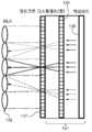
헤드 장착 광 필드 디스플레이들은 상이한 깊이들에서의 3D 장면의 투영들 또는 겉보기에 3D 장면에 의해 방출되고 상이한 눈 위치들로부터 뷰잉되는 광선들의 방향들을 샘플링함으로써 진정한 3D 장면을 렌더링한다. 이들은 정확한 또는 거의 정확한 초점 큐들을 렌더링하고, 종래의 VR 및 AR 디스플레이들에서의 수렴-조절 불일치 문제를 해결할 수 있다. 예를 들어, 통합 이미징(InI) 기반 디스플레이는 겉보기에 3D 장면에 의해 방출되고 상이한 눈 위치들로부터 뷰잉되는 광선들의 방향들을 각도 샘플링함으로써 3D 장면의 광 필드들을 재구성한다. 도 2에 도시된 바와 같이, 간단한 InI 기반 디스플레이는 일반적으로 디스플레이 패널, 및 마이크로 렌즈 어레이(microlens array; MLA) 또는 핀홀 어레이일 수 있는 2D 어레이를 포함한다. 디스플레이는 2D 요소 이미지들의 세트를 렌더링하며, 이들 각각은 3D 장면의 상이한 투시를 나타낸다. 요소 이미지들 내의 대응하는 픽셀들에 의해 방출된 원뿔형 광선 다발들은 교차하여, 광을 방출하고 3D 공간을 점유하는 것처럼 보이는 3D 장면의 인식을 통합적으로 생성한다. 2D 어레이들을 사용하는 InI 기반 디스플레이는 수평 및 수직 양방향에서의 최대 시차(full-parallax) 정보를 갖는 3D 형상의 재구성을 가능하게 하며, 이는 1차원 시차 장벽들 또는 원통형 렌티큘러 렌즈들을 사용하는 수평 시차만을 갖는 종래의 자동 입체 디스플레이와의 그의 중요한 차이이다. 1908년의 립만(Lippmann)에 의한 발표 이래로, InI 기반 기술은 실제 장면의 광 필드를 캡처하기 위한 것만 아니라, 무안경 자동 입체 디스플레이에서의 사용을 위해서도 광범위하게 탐구되었다. 이 기술은 낮은 횡방향 및 종방향 해상도, 좁은 피사계 심도(D0F) 및 좁은 뷰잉각에서의 그의 한계에 대해 알려졌다. 다른 모든 비입체 3D 디스플레이 기술에 비하여, InI 기술의 간단한 광학 아키텍처는 HMD 광학 시스템과 통합하여 착용 가능한 광 필드 디스플레이를 생성하는 것을 매력적이게 한다.Head mounted light field displays render a true 3D scene by sampling projections of the 3D scene at different depths or the directions of the rays that are apparently emitted by the 3D scene and viewed from different eye positions. They render accurate or nearly accurate focus cues and can solve the convergence-adjustment mismatch problem in conventional VR and AR displays. For example, integrated imaging (InI) based displays reconstruct light fields of a 3D scene by angularly sampling the directions of the rays that are apparently emitted by the 3D scene and viewed from different eye positions. As shown in FIG. 2, a simple InI based display generally includes a display panel and a 2D array, which may be a microlens array (MLA) or pinhole array. The display renders a set of 2D element images, each of which represents a different perspective of the 3D scene. The conical ray bundles emitted by corresponding pixels in the element images intersect, integratingly generating the perception of the 3D scene that emits light and appears to occupy 3D space. InI based displays using 2D arrays enable reconstruction of a 3D shape with full parallax information in both horizontal and vertical directions, which only horizontal parallax using one-dimensional parallax barriers or cylindrical lenticular lenses It is an important difference from the conventional autostereoscopic display having. Since the announcement by Lippmann in 1908, InI-based technology has been extensively explored for use in autostereoscopic stereoscopic displays, as well as for capturing the light field of real scenes. This technique is known for its limitations in low lateral and longitudinal resolution, narrow depth of field (D0F) and narrow viewing angle. Compared to all other non-stereoscopic 3D display technologies, the simple optical architecture of InI technology makes it attractive to create wearable light field displays integrating with HMD optical systems.
그러나, 다른 통합 이미징 기반 디스플레이 및 이미징 기술과 마찬가지로, 현재의 InI 기반 HMD 방법은 여러 주요 한계: (1) 좁은 시야(대각선으로 <30°); (2) 낮은 횡방향 해상도(시각 공간에서 약 10분각(arc minute)); (3) 낮은 종방향 해상도(시각 공간에서 약 0.5 디옵터); (4) 좁은 피사계 심도(depth of field; D0F)(10분각 해상도 기준에 대해 약 1 디옵터); (5) 누화 없는 뷰잉에 대한 제한된 아이박스(<5㎜); 및 (6) 뷰잉각의 제한된 해상도(>뷰잉당 20분각)를 겪는다. 이러한 한계들은 기술을 고성능 솔루션으로 채택하는 것에 대한 상당한 장벽을 생성할 뿐만 아니라, 잠재적으로는 조절-수렴 불일치 문제를 해결하는 것에 대한 기술의 유효성을 저하시킨다.However, as with other integrated imaging based display and imaging technologies, current InI based HMD methods have several major limitations: (1) narrow field of view (<30 ° diagonally); (2) low lateral resolution (about arc minute in visual space); (3) low longitudinal resolution (about 0.5 diopters in visual space); (4) narrow depth of field (D0F) (about 1 diopter for 10-minute resolution reference); (5) limited eyebox (<5 mm) for viewing without crosstalk; And (6) a limited resolution of the viewing angle (> 20 minutes per viewing). These limitations not only create significant barriers to the adoption of the technology as a high performance solution, but also potentially reduce the effectiveness of the technology for solving the regulation-convergence mismatch problem.
따라서, 본 개시는 위에 요약된 최신 기술의 성능 한계들의 일부 양태들을 극복하는 통합 이미징에 기초하는 고성능 헤드 장착 광 필드 디스플레이의 방법, 설계 및 실시예를 상술한다.Thus, the present disclosure details methods, designs, and embodiments of high performance head mounted light field displays based on integrated imaging that overcome some aspects of the performance limitations of the state of the art outlined above.
전술한 문제들에 응답하여, 본 발명의 양태들 중 하나에서, 본 발명은 높은 횡방향 및 종방향 해상도, 큰 피사계 심도, 누화 없는 아이박스 및 증가된 뷰잉각 해상도를 제공하는 통합 이미징에 기초하는 고성능 HMD를 제공한다.In response to the foregoing problems, in one of the aspects of the present invention, the present invention is based on integrated imaging providing high lateral and longitudinal resolution, large depth of field, no crosstalk eyebox, and increased viewing angle resolution. Provides a high performance HMD.
이를 위해, 본 발명은 선택된 포인트에 배치된 광 필드를 이미징하기 위한 자유형 도파관 프리즘으로서, 광 필드로부터 광을 수신하고, 수신된 광을 프리즘의 본체 내로 굴절시키도록 배치된 제1 자유형 광학 표면; 프리즘의 본체 내의 선택된 위치에서 광 필드의 중간 이미지를 제공하기 위해 제1 자유형 광학 표면으로부터 굴절된 광을 수신하고, 광을 프리즘의 본체 내로 반사하도록 배치된 제2 자유형 광학 표면; 중간 이미지로부터 광을 수신하고, 광을 프리즘의 본체 내로 내부 전반사하도록 배치된 제3 자유형 광학 표면; 및 제3 자유형 광학 표면으로부터 반사된 광을 수신하고, 광이 프리즘을 빠져나가게 하는 각도로 광을 다시 제3 자유형 표면으로 반사하도록 배치된 제4 자유형 광학 표면을 포함하고, 제1 내지 제4 자유형 광학 표면들은 제3 자유형 표면을 통해 프리즘을 빠져나가는 광이 프리즘 외부의 선택된 위치에서 광 필드의 이미지를 생성하게 하도록 협력하는, 자유형 도파관 프리즘을 제공할 수 있다. 제2 자유형 광학 표면은 광을 프리즘의 본체 내로 내부 전반사하도록 구성될 수 있고, 제3 자유형 광학 표면은 제2 자유형 광학 표면으로부터의 광을 프리즘의 본체 내로 내부 전반사하도록 구성될 수 있다. 직교 X-Y-Z 좌표계에 대해, Z축은 뷰잉 방향을 따를 수 있고, Y축은 사용자의 동공 사이 방향과 정렬된 수평 방향에 평행할 수 있고, X축은 사용자의 헤드 배향과 정렬된 수직 방향에 있을 수 있다. 자유형 도파관 프리즘은 수평 (Y-Z) 평면에 대해 대칭일 수 있고, 제1 내지 제4 자유형 광학 표면들은 수평 Y축을 따라 디센터링되고, 수직 X축에 대해 회전될 수 있다.To this end, the present invention provides a freeform waveguide prism for imaging a light field disposed at a selected point, comprising: a first freeform optical surface disposed to receive light from the light field and refracting the received light into the body of the prism; A second freeform optical surface disposed to receive light refracted from the first freeform optical surface to provide an intermediate image of the light field at a selected location within the body of the prism and to reflect light into the body of the prism; A third freeform optical surface disposed to receive light from the intermediate image and to totally reflect the light into the body of the prism; And a fourth freeform optical surface arranged to receive light reflected from the third freeform optical surface and reflect light back to the third freeform surface at an angle that causes the light to exit the prism; The optical surfaces can provide a freeform waveguide prism that cooperates to cause light exiting the prism through the third freeform surface to produce an image of the light field at a selected location outside the prism. The second freeform optical surface may be configured to totally internally reflect light into the body of the prism, and the third freeform optical surface may be configured to totally internally reflect light from the second freeform optical surface into the body of the prism. For an orthogonal X-Y-Z coordinate system, the Z axis can follow the viewing direction, the Y axis can be parallel to the horizontal direction aligned with the direction between the user's pupils, and the X axis can be in the vertical direction aligned with the user's head orientation. The freeform waveguide prism may be symmetric about the horizontal (Y-Z) plane, and the first to fourth freeform optical surfaces may be decentered along the horizontal Y axis and rotated about the vertical X axis.
또한, 본 발명은 헤드 장착 디스플레이 통합 이미징(InI) 시스템으로서, 시스템의 광축을 따라 선택된 위치에서 선택된 3D 장면의 광 필드들을 생성하도록 구성된 마이크로스코픽 InI(마이크로-InI) 유닛; 가변 초점 요소(vari-focal element; VFE)가 배치된 릴레이 유닛 - 릴레이 유닛은 선택된 위치가 릴레이 유닛의 광학 켤레가 되게 하는 로케이션에서 광축 상에 배치되고, 릴레이 유닛은 마이크로스코픽 InI 유닛에 의해 생성된 광 필드들을 수신하도록 구성됨 -; 및 헤드 장착 디스플레이 시스템의 사용자에 의한 뷰잉을 위해 시스템의 출구 동공에서 3D 장면의 이미지를 제공하기 위해 릴레이 유닛으로부터 광을 수신하기 위한 자유형 도파관 프리즘을 포함하고, VFE는 프리즘의 본체 내의 중간 이미지의 로케이션을 튜닝하도록 구성되는, 헤드 장착 디스플레이 통합 이미징(InI) 시스템을 제공할 수 있다. 마이크로스코픽 InI(마이크로-InI) 유닛은 제한된 뷰잉 구역을 갖는 3D 장면의 최대 시차 광 필드들을 재생하도록 구성될 수 있다. 릴레이 유닛은 제1 렌즈 그룹을 포함할 수 있고, VFE는 제1 렌즈 그룹의 후방 초점 거리에 위치한다. 시스템의 시야는 VFE의 광학적 파워와는 무관할 수 있고, VFE는 릴레이 유닛의 합성 광학적 파워가 VFE의 광학적 파워와는 무관하게 일정하게 유지되게 하는 로케이션에서 광축 상에 배치될 수 있다. 마이크로스코픽 InI 유닛은 마이크로 디스플레이를 포함할 수 있고, 자유형 도파관 프리즘을 통한 마이크로 디스플레이의 원호 필드 각도는 VFE의 광학적 파워와는 무관하게 일정하게 유지될 수 있다. 자유형 도파관 프리즘의 초점 거리는 27.5㎜일 수 있고, 시스템의 대각선 시야는 35°일 수 있고, 시스템은 픽셀당 2분각만큼 높은 광학 해상도를 가질 수 있다.The invention also provides a head mounted display integrated imaging (InI) system, comprising: a microscopic InI (micro-InI) unit configured to generate light fields of a selected 3D scene at a selected location along an optical axis of the system; Relay unit with a variable-focal element (VFE) disposed therein-the relay unit is disposed on the optical axis at a location that causes the selected position to be an optical pair of the relay unit, the relay unit being generated by the microscopic InI unit Configured to receive light fields; And a freeform waveguide prism for receiving light from the relay unit to provide an image of the 3D scene at the exit pupil of the system for viewing by a user of the head mounted display system, wherein the VFE is a location of an intermediate image within the body of the prism. A head mounted display integrated imaging (InI) system may be provided that is configured to tune a device. The microscopic InI (Micro-InI) unit may be configured to reproduce the maximum parallax light fields of the 3D scene with limited viewing area. The relay unit may comprise a first lens group, and the VFE is located at the rear focal length of the first lens group. The field of view of the system may be independent of the optical power of the VFE, and the VFE may be placed on the optical axis at a location such that the composite optical power of the relay unit remains constant irrespective of the optical power of the VFE. The microscopic InI unit may include a micro display, and the arc field angle of the micro display through the freeform waveguide prism may be kept constant regardless of the optical power of the VFE. The focal length of the freeform waveguide prism can be 27.5 mm, the diagonal field of view of the system can be 35 °, and the system can have an optical resolution as high as 2 minutes per pixel.
전술한 요약 및 본 발명의 예시적인 실시예들에 대한 다음의 상세한 설명은 첨부 도면들과 함께 읽을 때 더 이해될 수 있다. 도면들에서,
도 1은 아이피스가 마이크로 디스플레이 상에 렌더링된 이미지를 확대하고, 눈으로부터 고정된 먼 거리에 나타나는 가상 디스플레이를 형성하는 종래의 단안 HMD를 개략적으로 도시한다.
도 2는 통합 이미징에 기초하는 근안 광 필드 디스플레이(near-eye light field display)를 개략적으로 도시한다.
도 3a는 본 발명에 따른 고성능 InI 기반 헤드 장착 광 필드 디스플레이의 예시적인 구성을 개략적으로 도시한다.
도 3b는 본 발명에 따른 마이크로-InI 유닛의 예시적인 구성을 개략적으로 도시한다.
도 4a 내지 도 4d는 개구 어레이(도 4a), 프로그래밍 가능 공간 광 변조기(도 4b), 제어 가능한 지향성 방출 엔진을 갖는 디스플레이 소스(도 4c), 및 예시적인 제어 가능한 지향성 방출 엔진으로서 공간 광 변조기를 갖는 백라이트 소스(도 4d)를 사용함으로써 광선 방향 제어를 제공하도록 구성된 본 발명에 따른 마이크로-InI 유닛의 예시적인 구성을 개략적으로 도시한다.
도 5는 아이피스의 출구 동공에 켤레인 위치에 배치된 VFE(가변 초점 요소)를 갖는 본 발명에 따른 릴레이 그룹의 예시적인 구성을 개략적으로 도시한다.
도 6a 내지 도 6d는 가변 초점 릴레이 그룹의 일부가 아이피스에 통합된 자유형 도파관 프리즘을 사용하는 본 발명에 따른 광학 시스루 InI-HMD 설계의 예시적인 구성을 개략적으로 도시하며, 도 6a는 디스플레이 경로 레이아웃을 나타내고, 도 6b는 시스루 뷰 레이아웃을 나타내고, 도 6c는 확장된 시스루 뷰를 위한 도파관 프리즘의 세그먼트화된 배면을 나타내고, 도 6d는 도파관 프리즘의 배면의 정면 뷰를 나타낸다.
도 7a와 도 7b는 본 발명에 따른 InI-HMD 설계 구성의 2D 광학 레이아웃의 예시적인 구성을 개략적으로 도시하며, 도 7a는 광 필드 디스플레이 경로를 나타내고, 도 7b는 시스루 경로를 나타낸다.
도 8a와 도 8b는 축상 필드들(도 8a) 및 MLA(마이크로 렌즈 어레이)의 에지 근처의 가장 먼 MLA 요소의 필드들(도 8b)에 대한 3 디옵터의 재구성 중앙 깊이 평면(CDP) 깊이에 대한 MTF(modulation transfer function; 변조 전달 함수) 플롯들을 도시한다.
도 9a와 도 9b는 MLA에 대한 축상 필드들(도 9a) 및 MLA의 에지 근처의 가장 먼 MLA 요소의 필드들(도 9b)에 대한 2 디옵터의 재구성 CDP 깊이에 대한 MTF 플롯들을 도시한다.
도 10a와 도 10b는 MLA에 대한 축상 필드들(도 10a) 및 MLA의 에지 근처의 가장 먼 MLA 요소의 필드들(도 10b)에 대한 0 디옵터의 재구성 CDP 깊이에 대한 MTF 플롯들을 도시한다.
도 11a와 도 11b는 MLA에 대한 축상 필드들(도 11a) 및 MLA의 에지 근처의 가장 먼 MLA 요소의 필드들(도 11b)에 대한 0.25 디옵터만큼 CDP로부터 시프트된 재구성 포인트들에 대한 MTF 플롯들을 도시한다.
도 12a와 도 12b는 MLA에 대한 축상 필드들(도 12a) 및 MLA의 에지 근처의 가장 먼 MLA 요소의 필드들(도 12b)에 대한 0.5 디옵터만큼 CDP로부터 시프트된 재구성 포인트들에 대한 MTF 플롯들을 도시한다.
도 13a와 도 13b는 MLA에 대한 축상 필드들(도 13a) 및 MLA의 에지 근처의 가장 먼 MLA 요소의 필드들(도 13b)에 대한 0.75 디옵터만큼 CDP로부터 시프트된 재구성 포인트들에 대한 MTF 플롯들을 도시한다.
도 14a와 도 14b는 MLA에 대한 축상 필드들(도 14a) 및 MLA의 에지 근처의 가장 먼 MLA 요소의 필드들(도 14b)에 대한 1 디옵터만큼 CDP로부터 시프트된 재구성 포인트들에 대한 MTF 플롯들을 도시한다.
도 15는 시스루 경로 FOV 65°x 40°에 대한 MTF를 도시한다.The foregoing summary and the following detailed description of exemplary embodiments of the invention may be better understood when read in conjunction with the accompanying drawings. In the drawings,
1 schematically illustrates a conventional monocular HMD in which the eyepiece magnifies an image rendered on a micro display and forms a virtual display that appears at a fixed distance from the eye.
FIG. 2 schematically illustrates a near-eye light field display based on integrated imaging.
3A schematically illustrates an exemplary configuration of a high performance InI based head mounted light field display according to the present invention.
3b schematically illustrates an exemplary configuration of a micro-InI unit according to the present invention.
4A-4D illustrate an aperture array (FIG. 4A), a programmable spatial light modulator (FIG. 4B), a display source with a controllable directional emission engine (FIG. 4C), and a spatial light modulator as an exemplary controllable directional emission engine. An exemplary configuration of a micro-InI unit according to the present invention, which is configured to provide ray direction control by using a backlight source having FIG. 4D, is schematically illustrated.
5 schematically shows an exemplary configuration of a relay group according to the invention with a VFE (variable focus element) arranged in a conjugate position at the exit pupil of the eyepiece.
6A-6D schematically illustrate an exemplary configuration of an optical see-through InI-HMD design in accordance with the present invention using a freeform waveguide prism with a portion of a group of variable focus relays integrated into an eyepiece, and FIG. 6A shows a display path layout. 6B shows the see-through view layout, FIG. 6C shows the segmented back of the waveguide prism for the expanded see-through view, and FIG. 6D shows the front view of the back of the waveguide prism.
7A and 7B schematically show an exemplary configuration of a 2D optical layout of an InI-HMD design configuration according to the present invention, where FIG. 7A shows a light field display path and FIG. 7B shows a see-through path.
8A and 8B show the reconstruction center depth plane (CDP) depth of 3 diopters for the axial fields (FIG. 8A) and the fields of the furthest MLA element near the edge of the MLA (micro lens array) (FIG. 8B). Modulation transfer function (MTF) plots are shown.
9A and 9B show MTF plots for the reconstructed CDP depth of 2 diopters for on-axis fields for the MLA (FIG. 9A) and for the fields of the furthest MLA element near the edge of the MLA (FIG. 9B).
10A and 10B show MTF plots for the reconstructed CDP depth of zero diopters for on-axis fields (FIG. 10A) for the MLA and the fields of the furthest MLA element near the edge of the MLA (FIG. 10B).
11A and 11B show MTF plots for reconstruction points shifted from the CDP by 0.25 diopters for on-axis fields for the MLA (FIG. 11A) and for the fields of the furthest MLA element near the edge of the MLA (FIG. 11B). Illustrated.
12A and 12B show MTF plots for reconstruction points shifted from the CDP by 0.5 diopters for on-axis fields for the MLA (FIG. 12A) and for the fields of the furthest MLA element near the edge of the MLA (FIG. 12B). Illustrated.
13A and 13B show MTF plots for reconstruction points shifted from the CDP by 0.75 diopters for on-axis fields for the MLA (FIG. 13A) and for the fields of the furthest MLA element near the edge of the MLA (FIG. 13B). Illustrated.
14A and 14B show MTF plots for reconstruction points shifted from the CDP by 1 diopter for axial fields for the MLA (FIG. 14A) and for the fields of the furthest MLA element near the edge of the MLA (FIG. 14B). Illustrated.
15 shows the MTF for see-through path FOV 65 ° × 40 °.
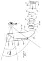
이제, 유사한 요소들이 전반적으로 유사하게 넘버링되는 도면들을 참조하면, 도 3a에 도시된 바와 같이, 본 발명에 따른 HMD 시스템(100)은 3개의 주요 서브시스템: I) 마이크로스코픽 InI(마이크로-InI) 유닛(130), II) InI 유닛(130)으로부터 광 필드들을 수신하도록 배치된 가변 초점 요소(VFE)(122)를 갖는 릴레이 그룹(120), 및 III) 릴레이 그룹(120)으로부터 튜닝된 중간 3D 장면을 수신하기 위한 아이피스 옵틱스(110)를 포함할 수 있다. 도 3b에 도시된 바와 같이, 마이크로-InI 유닛(130)은 제한된 뷰잉 구역으로부터 뷰잉된 3D 장면의 최대 시차 광 필드들을 재생할 수 있으며, 최대 시차 광 필드들은 수평 및 수직 뷰잉 방향들 양자로부터의 3D 장면의 뷰 투시들의 변화를 제공한다. 제한된 뷰잉 구역은 마이크로-InI 유닛(130)의 개구를 제한하는 것에 광학적으로 대응하고, 제한된 뷰잉 구역은 뷰잉자의 눈이 재구성된 3D 장면을 보기 위해 배치되는 디스플레이 시스템(100)의 출구 동공에 대한 광학적 켤레이다. 릴레이 그룹(120)은 그의 중앙 깊이 평면(CDP)의 튜닝 가능한 위치와 함께 마이크로-InI 유닛(130)에 의해 재구성된 3D 장면의 중간 이미지를 생성한다. 아이피스(110)의 배율에 따라, CDP의 위치는 약 0.5㎜ 내지 수백 밀리미터의 정도의 범위에서 튜닝 가능하여 광학적 무한대(0 디옵터) 내지 20cm(5 디옵터) 정도에 걸치는 큰 깊이 범위를 갖는 3D 장면의 인식을 생성할 수 있다. 릴레이 그룹(120)은 또한 재구성된 3D 장면(A0B)의 요면(concavity)의 반전(flip)을 용이하게 할 수 있다. 아이피스 옵틱스(110)는 튜닝 가능한 3D 광 필드들을 뷰잉자의 눈 내로 리이미징하고, 3D 광 필드들의 튜닝 가능한 깊이 범위를 수 미터 내지 수 센티미터의 큰 깊이 볼륨 간격으로 확대한다. 빔 분할기 기능을 갖는 옵틱스일 수 있는 시스루 유닛(도시되지 않음)은 시스루 뷰가 요구되는 경우에 실세계 장면의 두드러지지 않은 뷰를 광학적으로 가능하게 하기 위해 아이피스 옵틱스(110)와 광학적으로 통신할 수 있다. 도 3a의 마이크로-InI 유닛(130)은 도 3b에 추가로 도시된 바와 같이 고해상도 마이크로 디스플레이 및 마이크로 렌즈 어레이(MLA)(132)를 포함할 수 있다. MLA(132) 내의 렌즈릿들(133)의 초점 거리는


여기서,

도 3a와 도 4a에 도시된 바와 같이, 선택사항으로서, MLA(132)의 피치와 일치하는 광선 제한 개구들의 그룹을 포함하는 개구 어레이(136)가 마이크로 디스플레이(134)와 MLA(132) 사이에 삽입될 수 있다. 각각의 마이크로 렌즈(133)에 대응하는 작은 개구는 설계된 뷰잉 윈도우 내의 광선들이 옵틱스를 통해 전파되어 아이박스에 도달하는 것을 가능하게 하는 반면, 원치 않는 광선들이 인접한 마이크로 렌즈(133)에 도달하는 것을 차단하거나 인접한 요소 이미지들로부터의 광선들이 마이크로 렌즈(133)에 도달하는 것을 차단한다. 예를 들어, 개구 A1과 A2 사이의 흑색 구역은 포인트 P1에서 비롯된 점선 광선들이 렌즈릿(MLA1)에 인접한 MLA2에 도달하는 것을 차단한다. 이러한 차단된 광선들은 일반적으로 InI 디스플레이 시스템에서 관찰되는 뷰 누화 및 고스트 이미지들의 주요 요인이다. 마이크로 디스플레이(134)로부터 개구 어레이(136)까지의 거리는 ga로 표시되고, 개구 구멍의 직경은 pa로 표시되며, 이들은 다음 식들에 의해 제한될 수 있다.As shown in FIGS. 3A and 4A, an


여기서,

고정된 개구 크기를 갖는 개구 어레이(136)를 사용하는 것의 하나의 단점은 요소 이미지의 크기가 변할 경우에 각각의 요소 이미지의 에지 근처에 위치하는 픽셀들에 대한 광선들을 부분적으로 차단할 수 있다는 점이다. 도 4a에 도시된 바와 같이, 렌즈릿(MLA1)을 통해 전파되어야 하는 포인트 P1로부터의 광선들의 작은 부분이 개구 A1과 개구 A2 사이의 흑색 구역에 의해 차단되어, 원축오차(vignetting)와 같은 효과를 유발하며, 따라서 뷰잉자는 각각의 요소 이미지의 에지 근처의 포인트들에 대한 이미지 휘도의 감소를 관찰할 수 있다. 도 4b는 도 4a의 구성의 대안적인 구성을 도시하며, 이러한 대안적인 구성에서는 개구 어레이(136)가 프로그래밍 가능한 공간 광 변조기(SLM)(135)로 대체되어, 각각의 개구의 크기 및 형상이 원하는 광선들의 부분적 차단을 방지하도록 동적으로 적응될 수 있다. 도 4c는 마이크로 디스플레이(134) 및 개구 어레이(136)가 제어 가능한 지향성 방출을 갖는 디스플레이 소스(131)로 대체되는, 본 발명에 따른 마이크로-InI 유닛의 다른 실시예를 도시하며, 여기서 광 방출 방향은 각각의 픽셀로부터의 광선들이 그들의 대응하는 MLA 렌즈릿(133)에만 도달하도록 정밀하게 제어될 수 있다. 도 4d는 공간 광 변조기(135)가 비-방향 방출을 갖는 백라이트 소스(138)와 비-자기 방출 마이크로 디스플레이(137) 사이에 삽입되는 그러한 디스플레이 소스(131)의 하나의 가능한 구성을 도시한다. 공간 광 변조기(135)는 마이크로 디스플레이(137)를 조명하고 MLA(132)에 도달하는 광선들의 원뿔 각도를 프로그래밍하고 제어하도록 설정될 수 있다.One disadvantage of using an
종래의 InI 기반 디스플레이 시스템은 일반적으로 3D 재구성 포인트들의 깊이들이 CDP의 깊이로부터 시프트됨에 따른 공간 해상도의 급속한 저하로 인해 피사계 심도(DOF)의 제한을 겪을 수 있다. 예를 들어, 3D 장면 볼륨은 시각적 공간에서 3분각 이상의 공간 해상도를 유지하기 위해 0.5 디옵터 미만으로 제한될 필요가 있을 수 있다. 도 3a의 예시적인 구성에서와 같이, 높은 공간 해상도를 유지하면서 훨씬 더 큰 3D 장면 볼륨을 렌더링하기 위해, 내부에 샌드위치된 전자적으로 제어되는 가변 초점 요소(122)를 갖는 릴레이 그룹(120)이 마이크로-InI(130)와 아이피스(110) 사이에 삽입된다. 예시적인 VFE들(122)은 액체 렌즈, 액정 렌즈, 변형 가능한 미러, 또는 전기적으로 튜닝 가능한 광학 기술과 같은 임의의 다른 튜닝 가능한 광학 기술을 포함한다. VFE(122)에 상이한 전압들을 인가하여 릴레이 그룹(120)의 광학적 파워(φR)를 동적으로 제어함으로써, 릴레이 그룹(120)은 마이크로-InI(130)에 의해 생성된 재구성된 미니어처 3D 장면의 중간 이미지(A'O'B')를 형성한다. 릴레이된 중간 장면의 중앙 깊이 위치(CDP)는 아이피스(110)에 대해 축 방향으로(광축을 따라) 튜닝 가능하다. 결과적으로, 아이피스(110)에 의한 확대된 3D 가상 장면의 깊이 볼륨은 높은 횡방향 및 종방향 해상도를 유지하면서 매우 가까운 것(예를 들어, 5 디옵터)에서 매우 먼 것(예를 들어, 0 디옵터)으로 축 방향으로 시프트될 수 있다.Conventional InI based display systems can generally suffer from depth of field (DOF) due to the rapid drop in spatial resolution as the depths of the 3D reconstruction points are shifted from the depth of the CDP. For example, the 3D scene volume may need to be limited to less than 0.5 diopters to maintain spatial resolution of more than three minutes in visual space. As in the example configuration of FIG. 3A, the
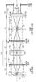
도 5는 마이크로-InI 유닛(130)에 인접한 전방 렌즈 그룹 "전방 릴레이"(126), 시스템 스톱으로 기능하는, 중간에 위치하는 VFE 옵틱스(122) 및 아이피스(110)에 인접한 후방 렌즈 그룹 "후방 릴레이"(124)를 포함하는, 도 3a의 릴레이 그룹(120)과 같은 가변 초점 릴레이 그룹(120)의 예시적인 구성을 개략적으로 도시한다. 릴레이 그룹(120)의 합성 파워(φR)는 다음 식에 의해 주어진다.5 shows the front lens group "front relay" 126 adjacent to the
[수학식 4][Equation 4]

여기서, φ1, φVFE 및 φ2는 각각 전방 렌즈 그룹(126), VFE(122) 및 후방 렌즈 그룹(124)의 광학적 파워이다. t1 및 t2는 전방 렌즈 그룹(126)과 VFE(122) 사이 및 VFE(122)와 후방 렌즈 그룹(124) 사이의 공간들이다. z0은 전방 렌즈 그룹과 마이크로-InI 유닛(130)에 의해 재구성된 3D 장면 사이의 축 방향 거리이다. 릴레이된 중간 장면의 축 방향 위치는 다음 식에 의해 주어진다.Here, φ1 , φVFE, and φ2 are optical powers of the

가변 초점 릴레이 시스템의 횡측 배율은 다음 식에 의해 주어진다.The lateral magnification of the variable focus relay system is given by the following equation.

φe가 아이피스(110)의 광학적 파워이고, ZRCDP가 릴레이된 CDP에서 아이피스(110)까지의 거리라고 가정하면, 아이피스(110)을 통한 재구성된 3D 가상 장면의 겉보기 CDP 위치는 다음 식에 의해 주어진다.Assuming that φe is the optical power of the

아이피스(110)을 통한 전체 시스템의 횡측 배율은 다음 식에 의해 주어진다.The lateral magnification of the entire system through the

아이피스(110)을 통한 전체 시스템의 시야(F0V)는 다음 식에 의해 주어진다.The field of view F0V of the entire system through the

여기서, t3은 아이피스(110)와 후방 릴레이 렌즈(124) 사이의 간격이고;


VFE(122)가 아이피스(110)의 출구 동공에 대한 광학적 켤레이도록 설정되고(즉,


도 5에 도시된 바와 같이, 가변 초점 릴레이 그룹(120)의 바람직한 실시예는 VFE(122)로 하여금 아이피스(110)의 출구 동공에 대한 광학적 켤레가 되게 하기 위해(즉,

수학식 6에 의해 주어지는 가변 초점 릴레이 시스템의 횡측 배율은 다음 식으로 단순화된다.The lateral magnification of the variable focus relay system given by

그리고, 수학식 8에 의해 주어지는 전체 시스템의 횡측 배율도 마찬가지이다.The same applies to the lateral magnification of the entire system given by Equation (8).
t1=1/φ1 및

수학식 10 내지 13에 의해 입증되는 바와 같이, 바람직한 방식에서의 VFE(122)의 세심한 위치는 릴레이 그룹(120)의 합성 광학적 파워가 객체-공간 텔레센트리시티(telecentricity)의 속성으로 인한 일정한 주 광선 방향들로 인해 VFE(122)의 광학적 파워와는 무관하게 일정하게 유지되는 것을 보장한다. 수학식 13에 의해 추가로 입증되는 바와 같이, 아이피스(110)를 통한 디스플레이의 원호 필드 각도(subtended field angle)는 또한 VFE(122)의 광학적 파워와는 무관하게 일정하게 유지된다. 릴레이 그룹(120)에 대한 일정한 광학적 파워를 유지하는 것은 가상적으로 재구성된 3D 장면이 CDP의 초점 깊이에 관계없이 일정한 시야를 달성하도록 돕는다. 따라서, 훨씬 더 큰 볼륨의 3D 장면이 시선 의존 또는 시간 다중화 모드에서 이음매 또는 아티팩트 없이 시각적으로 인식될 수 있다. 수학식 12에 의해 주어지는 릴레이 그룹(120)의 횡측 배율은 또한 t2=1/φ2가 충족되는 경우에 일정하게 유지될 수 있으며, 이는 가변 초점 릴레이 그룹(120)으로 하여금 이중 텔레센트릭 시스템이 되게 한다는 점에 유의할 가치가 있다.As demonstrated by Equations 10-13, the meticulous position of the
도 3a의 아이피스(110)는 많은 다른 형태를 취할 수 있다. 예를 들어, 광학 시스루 HMD의 간결한 광학적 설계를 달성하기 위해, 쐐기 형상의 자유형 프리즘이 채택될 수 있으며, 이를 통해 마이크로-InI 유닛(130) 및 릴레이 그룹(120)에 의해 재구성된 3D 장면이 확대되고 뷰잉된다. AR 시스템에 대한 시스루 능력을 가능하게 하기 위해, 표면들 중 하나가 빔 분할기 코팅으로 코팅된 자유형 교정기 렌즈가 프리즘 아이피스에 부착되어 자유형 프리즘에 의해 실세계 장면에 도입되는 뷰잉 축 편차 및 바람직하지 않은 수차를 교정할 수 있다.The
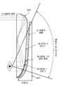
본 발명의 다른 양태에서, 릴레이 그룹(120)의 일부는 자유형 아이피스와 같은 아이피스 옵틱스(110)에 통합되어, 튜닝 가능한 중간 3D 장면이 자유형 아이피스 내에 형성되게 할 수 있다. 이러한 맥락에서, 아이피스는 예를 들어 쐐기 형상의 자유형 도파관 프리즘일 수 있다. 도 6a는 복수의 자유형 광학 표면에 의해 형성된 자유형 도파관 형태 프리즘(850)의 개념을 개략적으로 도시한다. 출구 동공은 사용의 눈이 확대된 3D 장면을 보도록 배치되는 곳에 위치한다. 이러한 설계에서, VFE(122)에 이어지는 전통적인 릴레이 그룹(220)의 일부는 프리즘(850)에 통합되며, "VFE를 갖는 릴레이 그룹"으로 표시된 박스 내에 포함된 자유형 도파관 프리즘(850)의 상부 부분(851)에 의해 충족된다. 3D 포인트(예를 들어, A)로부터 방출된 광선은 먼저 릴레이 그룹(220)의 가장 가까운 광학 요소(126)에 의해 굴절되어 프리즘(850) 내로 전송되고, 이어서 하나 또는 복수의 자유형 표면에 의해 반사되어 중간 이미지(예를 들어, A')를 생성한다. 중간 이미지(예를 들어, A')의 축 방향 위치는 VFE(122)에 의해 튜닝 가능하다. 후속 표면들에 의한 복수의 연속 반사 및 출구 표면(855)을 통한 최종 굴절은 광선이 시스템의 출구 동공에 도달하는 것을 가능하게 한다. 상이한 요소 이미지들로부터의 복수의 광선 다발이 존재할 수 있지만, 겉보기에는 동일한 객체 포인트로부터 그렇게 되며, 각각의 다발은 객체의 상이한 뷰를 나타내며, 출구 동공의 상이한 로케이션들 상에 입사한다. 이러한 광선 다발들은 눈앞에 위치하는 가상 3D 포인트(예를 들어, "A")를 통합적으로 재구성한다. 복수의 광학 요소를 필요로 하는 것이 아니라, 광학 경로가 다중 표면 프리즘(850) 내에서 자연스럽게 접히며, 이는 회전 대칭 요소들을 사용하는 설계와 비교할 때 옵틱스의 전체 볼륨 및 무게를 실질적으로 감소시키는 것을 돕는다. 전통적인 쐐기 형상의 3-표면 프리즘을 사용하는 설계와 비교할 때, 도파관 형태의 아이피스 설계는 릴레이 기능의 일부를 통합하여 독립형 릴레이 그룹(120)을 3-표면 프리즘과 결합하는 것보다 훨씬 더 간결한 시스템을 가능하게 한다. 간결함의 이점 외에도, 도파관 형태의 다중 접음 아이피스 설계는 훨씬 더 유리한 폼 팩터를 제공하는데, 이는 나머지 릴레이 그룹 및 마이크로-InI 유닛을 관자놀이 쪽에 수평으로 접을 수 있게 하기 때문이다. 다중 접음은 훨씬 더 균형 잡힌 무게를 갖는 시스템을 생성할 뿐만 아니라, 쐐기 형상 프리즘을 사용하는 것보다 실질적으로 더 큰 시스루 F0V를 가능하게 한다.In another aspect of the invention, a portion of
AR 시스템에 대한 시스루 능력을 가능하게 하기 위해, 도 6a의 프리즘(850)의, 아이피스 부분으로 표시된 배면의 하부 부분(853)은 빔 분할 미러로서 코팅될 수 있고, 적어도 2개의 자유형 광학 표면을 포함하는 자유형 교정기 렌즈(840)는 프리즘(850)의 배면에 부착되어, 자유형 프리즘(850)에 의해 실세계 장면에 도입되는 뷰잉 축 편차 및 바람직하지 않은 수차를 교정할 수 있다. 시스루 개략 레이아웃이 도 6b에 도시되어 있다. 가상 광 필드로부터의 광선들은 프리즘(850)의 배면에 의해 반사되는 반면, 실세계 장면으로부터의 광선들은 자유형 교정기 렌즈(840) 및 프리즘(850)을 통해 투과된다. 자유형 교정기 렌즈(840)의 전면은 프리즘(850)의 배면의 형상과 일치한다. 자유형 교정기 렌즈(840)의 배면은 렌즈가 프리즘(850)과 결합될 때 실세계 장면으로부터의 광선들에 도입되는 시프트 및 왜곡을 최소화하도록 최적화될 수 있다. 추가적인 교정기 렌즈 "보정기"는 전체 시스템의 풋프린트 및 무게를 현저히 증가시키지 않는다.To enable the see-through capability for the AR system, the
본 발명의 다른 양태에서, 도 6a의 프리즘(850)의, 아이피스 부분으로 표시된 배면의 하부 부분(853)은 세그먼트(853-1) 및 세그먼트(853-2)인 2개의 세그먼트로 분할될 수 있다. 도 6c에 개략적으로 도시된 바와 같이, 853-1의 세그먼트는 마이크로-InI 유닛에 의해 생성된 광 필드들을 수신하는 반사 또는 부분 반사 표면일 수 있다. 853-1 세그먼트 상의 빔 분할 미러 코팅은 또한 실세계 장면으로부터의 광선들의 투과를 가능하게 한다. 세그먼트(853-2)는 실세계 장면으로부터의 광선들만을 수신하는 투과성 또는 반투과성 표면이며, 마이크로-InI 유닛(130)에 의해 생성된 광 필드들을 수신하지 않는다. 도 6d는 프리즘(850)의 배면의 정면 뷰를 개략적으로 도시한다. 2개의 표면 세그먼트(853-1, 853-2)는 마이크로-InI 유닛(130)에 의해 재구성된 3D 광 필드들을 수신하는 데 필요한 개구 윈도우의 상부 경계에서 교차하며, 2개의 분리된 자유형 표면에 의해 형성될 수 있다. 배면(853)의 하부 부분을 상이한 광 경로들을 갖는 2개의 분리된 세그먼트(853-1, 853-2)로 분할하는 것은 가상 디스플레이 경로의 제약을 받지 않고 디스플레이 경로의 FOV를 너머 시스루 뷰의 FOV를 실질적으로 확대할 수 있는 능력을 제공한다. 도 6c에 도시된 바와 같이, 자유형 교정기 렌즈(840)가 프리즘(850)의 배면에 부착되어, 자유형 프리즘(850)에 의해 실세계 장면에 도입된 뷰잉 축 편차 및 바람직하지 않은 수차를 교정할 수 있다. 가상 광 필드로부터의 광선들은 프리즘(850)의 배면의 세그먼트(853-1)에 의해 반사되는 반면, 실세계 장면으로부터의 광선들은 프리즘(850)의 세그먼트들(853-1, 853-2) 및 자유형 교정기 렌즈(840) 양자를 통해 투과된다. 표면 세그먼트(853-2)는 자유형 교정기 렌즈(840)와 결합될 때 시스루 뷰의 시각적 아티팩트를 최소화하도록 최적화될 수 있다. 자유형 교정기 렌즈(840)의 전면은 프리즘(850)의 표면 세그먼트들(853-1, 853-2)의 형상과 일치한다. 자유형 교정기 렌즈(840)의 배면은 자유형 교정기 렌즈(840)가 프리즘(850)과 결합될 때 실세계 장면으로부터의 광선들에 도입되는 시프트 및 왜곡을 최소화하도록 최적화될 수 있다.In another aspect of the invention, the
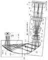
본 발명의 또 다른 양태에 따르면, 도 7a는 도 6a의 개념적 시스템을 구현하는 물리적 시스템의 광학 설계를 개략적으로 도시한다. 도 7a는 광 필드 디스플레이 경로의 2D 광학 레이아웃을 도시하고, 도 7b는 시스루 경로의 광학 레이아웃을 도시한다. 광 필드 디스플레이의 광학 시스템은 마이크로-InI 유닛, VFE를 갖는 릴레이 그룹 및 자유형 도파관을 포함한다. 릴레이 그룹의 일부는 도파관에 통합될 수 있다. 마이크로-InI 유닛은 마이크로 디스플레이(S0), 핀홀 어레이(S1) 및 마이크로 렌즈 어레이(S2)를 포함할 수 있다. 릴레이 그룹은 4개의 렌즈, 시판되는 VFE(Optotune Inc.의 전기 렌즈 EL 10-30) 및 2개의 자유형 표면(표면 S19 및 S20)을 포함할 수 있다. 자유형 도파관 프리즘(900)은 각각 S19, S20, S21 및 S22로 표시된 복수의 자유형 광학 표면에 의해 형성될 수 있다. 이러한 설계에서, VFE에 이어지는 전통적인 릴레이 그룹의 일부는 프리즘(900)에 통합될 수 있고, 표면 S19 및 S20에 의해 충족될 수 있다. 3D 포인트(예를 들어, A)로부터 방출된 광선은 먼저 프리즘(900)의 표면(S19)에 의해 굴절되고, 이어서 표면(S20)에 의해 반사되어 중간 이미지(예를 들어 A')를 생성한다. 중간 이미지(예를 들어, A')의 축 방향 위치는 VFE에 의해 튜닝 가능하다. 표면 S21' 및 S22-1에 의한 2개 이상의 연속 반사 및 표면 S21을 통한 최종 굴절은 광선이 시스템의 출구 동공에 도달할 수 있게 한다. 상이한 요소 이미지들로부터의 그러나 겉보기에는 동일한 객체 포인트로부터의 복수의 광선 다발이 존재하며, 이들 각각은 객체의 상이한 뷰를 나타내며, 출구 동공의 상이한 로케이션들 상에 입사한다. 이러한 광선 다발들은 눈앞에 위치하는 가상 3D 포인트를 통합적으로 재구성한다. 도파관의 표면 S21'에 의해 반사된 광선들은 내부 전반사의 조건을 만족시켜야 한다. 프리즘(900)의 배면들(S22-1, S22-2)은 실세계 장면의 뷰를 차단하는 몰입형 HMD 시스템을 구축하기 위해 미러 코팅으로 코팅될 수 있다. 대안적으로, 표면(S22-1)은 도 7b에 도시된 바와 같이 보조 렌즈를 사용하여 광학 시스루 능력이 요구되는 경우에 빔 분할 코팅으로 코팅될 수 있다.According to another aspect of the present invention, FIG. 7A schematically illustrates an optical design of a physical system implementing the conceptual system of FIG. 6A. FIG. 7A shows the 2D optical layout of the light field display path, and FIG. 7B shows the optical layout of the see-through path. The optical system of the light field display includes a micro-InI unit, a relay group having a VFE, and a freeform waveguide. Part of the relay group can be integrated into the waveguide. The micro-InI unit may include a micro display SO, a pinhole array S1 and a micro lens array S2. The relay group may comprise four lenses, commercially available VFE (Optotune Inc. electric lens EL 10-30) and two freeform surfaces (surfaces S19 and S20).
여기에 개시된 설계에서, Z축은 뷰잉 방향을 따르고, Y축은 동공 사이 방향과 정렬되는 수평 방향과 평행하고, X축은 헤드 배향과 정렬되는 수직 방향이라는 점에 유의해야 한다. 결과적으로, 전체 도파관 시스템은 수평(YOZ) 평면에 대해 대칭이고, 광학 표면들(S19, S20, S21, S22)은 수평 Y축을 따라 디센터링되고, 수직 X축에 대해 회전된다. 광학 경로는 수평(YOZ) 평면에서 접힌다. 이러한 배열은 마이크로-InI 유닛 및 가변 초점 릴레이 그룹이 사용자 헤드의 관자놀이 쪽에 장착되는 것을 가능하게 하여, 결과적으로 균형 잡힌 인체 공학적 시스템 패키징을 가능하게 한다.In the design disclosed herein, it should be noted that the Z axis is along the viewing direction, the Y axis is parallel to the horizontal direction aligned with the interpupillary direction, and the X axis is a vertical direction aligned with the head orientation. As a result, the entire waveguide system is symmetrical about the horizontal (YOZ) plane, and the optical surfaces S19, S20, S21, S22 are decentered along the horizontal Y axis and rotated about the vertical X axis. The optical path is folded in the horizontal (YOZ) plane. This arrangement allows the micro-InI unit and the variable focus relay group to be mounted on the temple side of the user head, resulting in a balanced ergonomic system packaging.
표 1은 도 7a의 시스템에 대한 주요 성능 사양들 중 일부를 강조하였다. 시스템은 35°의 대각선 FOV에 대응하는 3D 장면의 진정한 3D 광 필드를 렌더링하는 능력을 제공하며, 시각적 공간에서 픽셀당 2분각 정도의 높은 광학 해상도를 달성한다. 또한, 시스템은 단안 디스플레이에 대해 약 0.1 디옵터의 높은 종방향 해상도와 함께 0 내지 5 디옵터로 튜닝 가능한 큰 깊이 범위를 제공한다. 또한, 시스템은 약 0.5/㎜2의 높은 뷰 밀도를 달성하며, 뷰 밀도 σ는 출구 동공 상의 단위 면적당 고유 뷰들의 수로 정의되고, 다음 식에 의해 주어진다.Table 1 highlights some of the key performance specifications for the system of FIG. 7A. The system provides the ability to render a true 3D light field of a 3D scene that corresponds to a 35 ° diagonal FOV and achieves high optical resolution of about 2 minutes per pixel in visual space. The system also provides a large depth range that can be tuned from 0 to 5 diopters with a high longitudinal resolution of about 0.1 diopters for monocular display. In addition, the system achieves a high view density of about 0.5 / mm2 , where the view density σ is defined as the number of inherent views per unit area on the exit pupil and is given by the following equation.

여기서, N은 뷰들의 총 수이고, AXP는 디스플레이 시스템의 출구 동공의 면적이다. 0.5/㎜2의 뷰 밀도는 0.2 디옵터의 거리에 있는 객체에 대한 약 1분각의 뷰잉각 해상도와 같다. 디스플레이의 아이박스로도 알려진, 누화 없는 뷰잉을 위한 출구 동공 직경은 약 6㎜이다. 이 실시예에서, 출구 동공 직경은 상업용 VFE의 개구 크기에 의해 제한되며, 다른 더 큰 개구의 VFE가 채택되는 경우에 증가될 수 있다. 마지막으로, 시스템은 수평 65° 및 수직 40°보다 큰 시스루 F0V를 제공한다. 본 출원인의 프로토타입에서 이용되는 마이크로 디스플레이는 8㎛ 컬러 픽셀 및 1920x1080 의 픽셀 해상도를 갖는 0.7 인치 유기 발광 디스플레이(OLED)(소니의 ECX335A)이다. 그러나, 광학 설계 자체는 상이한 치수의 0LED 패널 또는 다른 타입의 마이크로 디스플레이, 예를 들어 6㎛보다 큰 컬러 픽셀 크기를 갖는 액정 디스플레이를 지원할 수 있다.Where N is the total number of views and AXP is the area of the exit pupil of the display system. A view density of 0.5 / mm2 is equal to a viewing angle resolution of about one minute for an object at a distance of 0.2 diopters. The exit pupil diameter for crosstalk-free viewing, also known as the eyebox of the display, is about 6 mm. In this embodiment, the exit pupil diameter is limited by the opening size of the commercial VFE and can be increased if the VFE of another larger opening is adopted. Finally, the system provides a see-through F0V greater than 65 ° horizontal and 40 ° vertical. The micro display used in Applicant's prototype is a 0.7 inch organic light emitting display (OLED) (Sony's ECX335A) with an 8 μm color pixel and a pixel resolution of 1920 × 1080. However, the optical design itself can support 0LED panels of different dimensions or other types of micro displays, for example liquid crystal displays having color pixel sizes larger than 6 μm.
<표 1 - 1차 시스템 사양들>Table 1-Primary System Specifications
표 2 내지 5에서 광학 표면 데이터의 형태로 도 7a의 시스템의 예시적인 구현이 제공된다. 표 2는 디스플레이 경로의 기본 파라미터들을 요약한 것이다(단위: ㎜). 표 3 내지 5는 비구면 광학 표면들을 정의하는 최적화된 계수들을 제공한다.In Tables 2-5 an exemplary implementation of the system of FIG. 7A is provided in the form of optical surface data. Table 2 summarizes the basic parameters of the display path in mm. Tables 3-5 provide optimized coefficients that define aspherical optical surfaces.
<표 2 - InI-HMD 디스플레이 경로의 광학 사양들>Table 2-Optical Specifications of InI-HMD Display Path
고해상도 가상 재구성 3D 이미지를 얻기 위해 6㎛ 정도의 작은 픽셀들을 갖는 고해상도 마이크로 디스플레이가 채택된다. 마이크로-InI 유닛에 대한 이러한 고해상도 이미징을 달성하기 위해, 비구면 표면들에 의해 형성된 마이크로 렌즈 어레이(MLA)가 특별히 설계될 수 있다. MLA의 비구면 표면들 각각은 다음과 같이 설명될 수 있다.High resolution virtual reconstruction A high resolution micro display with pixels as small as 6 μm is employed to obtain a 3D image. To achieve this high resolution imaging of the micro-InI unit, a micro lens array (MLA) formed by aspherical surfaces can be specially designed. Each of the aspherical surfaces of the MLA can be described as follows.

여기서 z는 국소 x, y, z 좌표계의 z축을 따라 측정된 표면의 휨(sag)이고, c는 정점 곡률이고, r은 반경 거리이고, k는 원뿔 상수이고, A 내지 E는 각각 4차, 6차, 8차, 10차 및 12차 변형 계수이다. MLA의 재료는 PMMA이다. 표 3은 표면들(S1, S2)에 대한 계수들을 제공한다.Where z is the sag of the surface measured along the z axis of the local x, y, z coordinate system, c is the vertex curvature, r is the radial distance, k is the conical constant, and A to E are each quadratic, 6th, 8th, 10th, and 12th order coefficients of deformation The material of the MLA is PMMA. Table 3 provides the coefficients for the surfaces S1 and S2.
<표 3 - 마이크로 렌즈 어레이(MLA)에 대한 비구면 표면 정의들>Table 3-Aspheric Surface Definitions for Micro Lens Array (MLA)
확대된 시스루 F0V를 가능하게 하기 위해, 자유형 도파관 프리즘(900)은 각각 표면 S19, S20, S21/S21', S22-1 및 S22-2로 표시된 5개의 자유형 표면에 의해 형성될 수 있다. 자유형 교정기 렌즈는 2개의 자유형 표면에 의해 형성될 수 있으며, 이들 중 전면은 도파관 프리즘(900)의 표면들(S22-1, S22-2)과 동일한 표면 사양들을 공유하고, 배면은 표면 S23으로 표시된다. S22-1의 표면 세그먼트는 마이크로-InI 유닛에 의해 생성된 광 필드들을 수신하는 반사성 또는 부분 반사성 표면이다. S22-1의 세그먼트 상의 빔 분할 미러 코팅은 또한 시스루 능력을 위해 실세계 장면으로부터의 광선들의 투과를 가능하게 한다. 표면 세그먼트 S22-2는 실세계 장면으로부터의 광선들만을 수신하는 투과성 또는 반투과성 표면이며, 마이크로-InI 유닛에 의해 생성된 광 필드들을 수신하지 않는다.To enable enlarged see-through F0V,
S19, S20, S21/S21', S22-1 및 S23을 포함하는 자유형 표면들은 수학적으로 다음과 같이 설명될 수 있다.Freeform surfaces including S19, S20, S21 / S21 ', S22-1, and S23 can be mathematically described as follows.

여기서, z는 국소 x, y, z 좌표계의 z 축을 따라 측정된 자유형 표면의 휨이고, c는 정점 곡률(CUY)이고, r은 반경 거리이고, k는 원뿔 상수이고, Cj는 xmyn에 대한 계수이다. 도파관 프리즘 및 보정 렌즈 양자의 재료는 PMMA이다. 표 4 내지 8은 각각 표면 S19 내지 S21, S22-1 및 S23에 대한 계수들을 제공하며, 표 9는 각각의 광학 표면의 표면 기준들을 제공한다.Where z is the curvature of the freeform surface measured along the z axis of the local x, y, z coordinate system, c is the vertex curvature (CUY), r is the radial distance, k is the cone constant, and Cj is xm y coefficient forn . The material of both the waveguide prism and the correcting lens is PMMA. Tables 4 to 8 provide coefficients for surfaces S19 to S21, S22-1 and S23, respectively, and Table 9 provides surface references for each optical surface.
설계 프로세스 동안, 표면 세그먼트(S22-1)의 사양들은 마이크로-InI 유닛, 릴레이 렌즈 그룹 및 표면들(S19, S20, S21/21', S22-1)로 구성된 프리즘(900)을 통한 광 필드 디스플레이 경로의 최적화 후에 획득되었다. 표면들(S20, S22-1)의 필요한 개구 치수들은 광 필드 디스플레이 경로에 대해 먼저 결정되었다. 이어서, 표면들(S22, S21, S22-1)은 표면(S22-2)을 생성한 Solidworks®와 같은 3D 모델링 소프트웨어 내로 넣어졌다. 표면(S22-2)의 형상은 다음 요건들: (1) 디스플레이에 의해 정의된 표면(S22-1)에 대한 필요한 개구의 상부 경계 라인을 따라 또는 그 위에서 표면(S22-1)과 교차하는 요건; (2) 표면 S22-2와 S22-2 사이의 교차 라인을 따라, 표면(S22-2) 상의 교차 포인트들에서의 표면 기울기들이 표면(S22-1) 상의 그러한 대응하는 포인트들과 동일하지는 않더라도 대략 일치하여, 2개의 표면이 거의 연속적으로 보이는 것을 보장하여, 일치하는 자유형 교정기 렌즈와 결합될 때 시스루 뷰에 대한 시각적 아티팩트를 최소화하는 요건; (3) 표면(S22-2)이 디스플레이 경로에 의해 정의된 표면(S20)에 대한 필요한 개구의 하부 경계 라인을 따라 또는 그 아래에서 표면(S20)과 교차하는 요건; 및 (4) 표면 S21과 S22-2 사이의 전체 두께가 최소화되는 요건을 충족시킴으로써 모델링 소프트웨어에서 생성되었다. 마지막으로, 밀폐된 자유형 도파관 프리즘을 생성하기 위해 표면들(S19, S20, S21/21', S22-1)과 결합되는 표면(S22-2)의 자유형 형상이 3D 모델링 소프트웨어에서 획득된다. 도 7b는 전술한 방법을 통해 실질적으로 확대된 시스루 FOV를 나타낸다.During the design process, the specifications of the surface segment S22-1 are light field display through the
<표 4 - 자유형 표면 S19에 대한 표면 정의>Table 4-Surface Definition for Freeform Surface S19
<표 5 - 자유형 표면 S20에 대한 표면 정의>Table 5-Surface Definition for Freeform Surface S20
<표 6 - 자유형 표면 S21/21'에 대한 표면 정의>Table 6-Surface definition for freeform surface S21 / 21 '
<표 7 - 자유형 표면 S22-1에 대한 표면 정의>Table 7-Surface Definition for Freeform Surface S22-1
<표 8 - 자유형 표면 S23에 대한 표면 정의>Table 8-Surface Definition for Freeform Surface S23
<표 9 - 전역 좌표계에서의 국소 표면 기준들의 정의>Table 9-Definition of local surface references in the global coordinate system
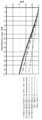
설계 프로세스 동안, 선택된 OLED 마이크로 디스플레이 내의 청색, 녹색 및 적색 방출기들의 피크 방출 스펙트럼들에 대응하는 3개의 대표적인 파장 465㎚, 550㎚ 및 630㎚가 선택되었다. MLA 내의 총 21개의 렌즈릿이 샘플링되었고, 이들 각각은 9개의 요소 이미지 포인트를 나타내며, 이들은 총 189개의 필드 샘플을 추가했다. 이미지 품질을 평가하기 위해, 아이피스와 동일한 파워를 갖는 이상적인 렌즈가 시스템의 출구 동공(뷰잉 윈도우)에 배치되었으며, 결과적으로 마이크로 디스플레이의 픽셀 크기에 의해 제한된 최종 이미지에 대한 20.83 lp/㎜의 컷오프 주파수를 유발하였다. 설계된 시스템의 광학 성능은 3개의 설계 파장에 대한 대표적인 필드 각도들에서 평가되었다. 튜닝 가능 렌즈 VFE의 광학적 파워를 변경함으로써, 광학적 성능의 현저한 저하 없이 중앙 깊이 평면이 예를 들어 0 내지 3 디옵터의 큰 범위에서 축 방향으로 시프트될 수 있었다. 도 8 내지 10은 각각 3, 1 및 0 디옵터의 깊이에서 CDP 세트 상에 재구성된 포인트들에 대한 다색 변조 전달 함수(MTF)를 플로팅한다. 각각의 CDP 위치에 대해, 2 세트의 MTF들이 플로팅되었고, 이들 중 하나는 축상 MLA에 대응하는 필드들에 대한 것이고, 다른 하나는 에지 근처의 가장 먼 MLA에 대응하는 필드들에 대한 것이다.During the design process, three representative wavelengths 465 nm, 550 nm and 630 nm were selected that correspond to the peak emission spectra of the blue, green and red emitters in the selected OLED micro display. A total of 21 lenslets in the MLA were sampled, each representing 9 element image points, which added a total of 189 field samples. To evaluate image quality, an ideal lens with the same power as the eyepiece was placed in the exit pupil of the system (viewing window), resulting in a cutoff frequency of 20.83 lp / mm for the final image limited by the pixel size of the micro display. Induced. The optical performance of the designed system was evaluated at representative field angles for three design wavelengths. By changing the optical power of the tunable lens VFE, the center depth plane could be shifted in the axial direction, for example, in a large range of 0 to 3 diopters without significant degradation in optical performance. 8-10 plot the multicolor modulation transfer function (MTF) for reconstructed points on a CDP set at depths of 3, 1 and 0 diopters, respectively. For each CDP location, two sets of MTFs were plotted, one of which is for fields corresponding to on-axis MLA, and the other is for fields corresponding to the furthest MLA near the edge.
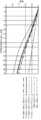
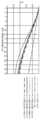
한편, 재구성된 이미지가 특정 튜닝 가능 상태에 대해 중앙 깊이 평면으로부터 시프트될 때 3D 재구성 포인트의 이미지 품질이 어떻게 저하되는지를 평가하는 것도 똑같이 중요하다. 이것은 튜닝 가능 렌즈의 광학적 파워를 변경하지 않고 중앙 깊이 평면을 적은 양의 거리만큼 시프트시킴으로써 평가될 수 있다. 도 11 내지 14는 각각 0.25, 0.5, 0.75 및 1 디옵터만큼 CDP로부터 시프트된 재구성된 포인트들에 대한 다색 MTF를 플로팅한다. 각각의 깊이에 대해, 2 세트의 MTF들이 플로팅되었으며, 이들 중 하나는 축상 MLA에 대응하는 필드들에 대한 것이고, 다른 하나는 에지 근처의 가장 먼 MLA에 대응하는 필드들에 대한 것이다.On the other hand, it is equally important to evaluate how the image quality of the 3D reconstruction point is degraded when the reconstructed image is shifted from the center depth plane for a particular tunable state. This can be evaluated by shifting the central depth plane by a small amount of distance without changing the optical power of the tunable lens. 11 through 14 plot the multicolored MTF for reconstructed points shifted from CDP by 0.25, 0.5, 0.75 and 1 diopter, respectively. For each depth, two sets of MTFs were plotted, one of which is for the fields corresponding to the on-axis MLA and the other is for the fields corresponding to the furthest MLA near the edge.
도 15는 65°x 40°F0V에 대한 다색 MTF를 플로팅한다. 전체 F0V에 걸쳐, 시스루 경로는 20/20 정상 비전에 대응하는 30 사이클/각도 주파수에서의 50% 초과 및 20/20 비전 또는 0.5분각의 시력에 대응하는 60 사이클/각도 주파수에서의 약 20%의 평균 MTF 값을 달성하였다.15 plots the multicolor MTF for 65 ° × 40 ° F0V. Over the entire F0V, the see-through path is greater than 50% at 30 cycles / angle frequency corresponding to 20/20 normal vision and about 20% at 60 cycles / angle frequency corresponding to 20/20 vision or 0.5 minute vision. Average MTF values were achieved.
Claims (23)
Translated fromKorean상기 광 필드로부터 광을 수신하고, 상기 수신된 광을 상기 프리즘의 본체 내로 굴절시키도록 배치된 제1 자유형 광학 표면;
상기 프리즘의 본체 내의 선택된 위치에서 상기 광 필드의 중간 이미지를 제공하기 위해 상기 제1 자유형 광학 표면으로부터 상기 굴절된 광을 수신하고, 상기 광을 상기 프리즘의 본체 내로 반사하도록 배치된 제2 자유형 광학 표면;
상기 중간 이미지로부터 상기 광을 수신하고, 상기 광을 상기 프리즘의 본체 내로 내부 전반사하도록 배치된 제3 자유형 광학 표면; 및
상기 제3 자유형 광학 표면으로부터 상기 반사된 광을 수신하고, 상기 광이 상기 프리즘을 빠져나가게 하는 각도로 상기 광을 다시 상기 제3 자유형 표면으로 반사하도록 배치된 제4 자유형 광학 표면
을 포함하고, 상기 제1 자유형 광학 표면 내지 상기 제4 자유형 광학 표면은 상기 제3 자유형 표면을 통해 상기 프리즘을 빠져나가는 광이 상기 프리즘 외부의 선택된 위치에서 상기 광 필드의 이미지를 생성하게 하도록 협력하는 것인, 자유형 도파관 프리즘.A freeform waveguide prism for imaging a light field disposed at a selected point,
A first freeform optical surface arranged to receive light from the light field and refracting the received light into the body of the prism;
A second freeform optical surface arranged to receive the refracted light from the first freeform optical surface to provide an intermediate image of the light field at a selected location within the body of the prism and to reflect the light into the body of the prism ;
A third freeform optical surface arranged to receive the light from the intermediate image and to totally reflect the light into the body of the prism; And
A fourth freeform optical surface arranged to receive the reflected light from the third freeform optical surface and reflect the light back to the third freeform surface at an angle that causes the light to exit the prism
Wherein the first freeform optical surface to the fourth freeform optical surface cooperate to cause light exiting the prism through the third freeform surface to produce an image of the light field at a selected location outside the prism. Freestyle waveguide prism.
상기 제2 자유형 광학 표면은 상기 광을 상기 프리즘의 본체 내로 내부 전반사하도록 구성된 것인, 자유형 도파관 프리즘.The method of claim 1,
And the second freeform optical surface is configured to totally internally reflect the light into the body of the prism.
상기 제2 자유형 광학 표면은 상기 광을 상기 프리즘의 본체 내로 반사하도록 미러링된 것인, 자유형 도파관 프리즘.The method of claim 1,
And the second freeform optical surface is mirrored to reflect the light into the body of the prism.
상기 제3 자유형 광학 표면은 상기 제2 자유형 광학 표면으로부터의 상기 광을 상기 프리즘의 본체 내로 내부 전반사하도록 구성된 것인, 자유형 도파관 프리즘.The method according to any one of claims 1 to 3,
And the third freeform optical surface is configured to totally internally reflect the light from the second freeform optical surface into the body of the prism.
상기 제4 자유형 광학 표면은 미러링된 것인, 자유형 도파관 프리즘.The method according to any one of claims 1 to 4,
And the fourth freeform optical surface is mirrored.
상기 제4 자유형 광학 표면은 빔 분할 코팅을 포함한 것인, 자유형 도파관 프리즘.The method according to any one of claims 1 to 5,
And the fourth freeform optical surface comprises a beam split coating.
직교 X-Y-Z 좌표계에 대해, Z축은 뷰잉(viewing) 방향을 따르고, Y축은 사용자의 동공 사이 방향과 정렬된 수평 방향에 평행하고, X축은 상기 사용자의 헤드 배향과 정렬된 수직 방향에 있는 것인, 자유형 도파관 프리즘.The method according to any one of claims 1 to 6,
For an orthogonal XYZ coordinate system, the Z axis follows the viewing direction, the Y axis is parallel to the horizontal direction aligned with the direction between the user's pupils, and the X axis is in the vertical direction aligned with the user's head orientation. Waveguide Prism.
상기 자유형 도파관 프리즘은 수평 (Y-Z) 평면에 대하여 대칭인 것인, 자유형 도파관 프리즘.The method of claim 7, wherein
And the freeform waveguide prism is symmetric about a horizontal (YZ) plane.
상기 제1 자유형 광학 표면 내지 상기 제4 자유형 광학 표면은 상기 수평 Y축을 따라 디센터링(decentering)되고, 상기 수직 X축에 대해 회전되는 것인, 자유형 도파관 프리즘.The method according to claim 7 or 8,
And the first freeform optical surface to the fourth freeform optical surface are decentered along the horizontal Y axis and rotated about the vertical X axis.
상기 제1 내지 제4 자유형 광학 표면들 중 어느 하나의 형상은 다음 식,

에 의해 주어지며, 여기서, z는 국소 x, y, z 좌표계의 z 축을 따라 측정된 상기 자유형 표면의 휨(sag)이고, c는 정점 곡률(CUY)이고, r은 반경 거리이고, k는 원뿔 상수이고, Cj는 xmyn에 대한 계수인 것인, 자유형 도파관 프리즘.The method according to any one of claims 1 to 9,
The shape of any one of the first to fourth freeform optical surfaces is
Where z is the sag of the freeform surface measured along the z axis of the local x, y, z coordinate system, c is the vertex curvature (CUY), r is the radial distance, and k is the cone A constant, and Cj is a coefficient for xm yn .
상기 시스템의 광축을 따라 선택된 위치에서 선택된 3D 장면의 광 필드들을 생성하도록 구성된 마이크로스코픽 InI(마이크로-InI) 유닛;
가변 초점 요소(vari-focal element; VFE)가 배치된 릴레이 유닛 - 상기 릴레이 유닛은 상기 선택된 위치가 상기 릴레이 유닛의 광학적 켤레(optical conjugate)가 되게 하는 로케이션에서 상기 광축 상에 배치되고, 상기 릴레이 유닛은 상기 마이크로스코픽 InI 유닛에 의해 생성된 상기 광 필드들을 수신하도록 구성됨 -; 및
상기 헤드 장착 디스플레이 시스템의 사용자에 의한 뷰잉을 위해 상기 시스템의 출구 동공에서 상기 3D 장면의 이미지를 제공하기 위해 상기 릴레이 유닛으로부터 광을 수신하기 위한 제1항 내지 제10항 중 어느 한 항에 따른 상기 자유형 도파관 프리즘
을 포함하고,
상기 VFE는 상기 프리즘의 본체 내의 상기 중간 이미지의 로케이션을 튜닝하도록 구성된 것인, 헤드 장착 디스플레이 통합 이미징(InI) 시스템.Head mounted display integrated imaging (InI) system,
A microscopic InI (micro-InI) unit configured to generate light fields of a selected 3D scene at a selected location along the optical axis of the system;
A relay unit having a variable-focal element (VFE) disposed therein, the relay unit being disposed on the optical axis at a location such that the selected position is an optical conjugate of the relay unit, the relay unit Is configured to receive the light fields generated by the microscopic InI unit; And
The method according to any one of claims 1 to 10, for receiving light from the relay unit to provide an image of the 3D scene at the exit pupil of the system for viewing by a user of the head mounted display system. Hand drawn waveguide prism
Including,
And the VFE is configured to tune the location of the intermediate image within the body of the prism.
상기 마이크로스코픽 InI(마이크로-InI) 유닛은 제한된 뷰잉 구역을 갖는 3D 장면의 최대 시차(full-parallax) 광 필드들을 재생하도록 구성된 것인, 헤드 장착 디스플레이 통합 이미징(InI) 시스템.The method of claim 10,
And the microscopic InI (Micro-InI) unit is configured to reproduce full-parallax light fields of a 3D scene with a limited viewing area.
실세계의 뷰를 상기 자유형 도파관 프리즘에 전송하기 위해 상기 자유형 도파관 프리즘과 광학적으로 통신하는 시스루 유닛(see-through unit)을 포함하는 자유형 도파관 프리즘 또는 헤드 장착 디스플레이 통합 이미징(InI) 시스템.The method according to any one of claims 1 to 12,
A freeform waveguide prism or head mounted display integrated imaging (InI) system comprising a see-through unit in optical communication with the freeform waveguide prism for transmitting a view of a real world to the freeform waveguide prism.
상기 릴레이 유닛은 제1 렌즈 그룹을 포함하고, 상기 VFE는 상기 제1 렌즈 그룹의 후방 초점 거리에 위치한 것인, 헤드 장치 디스플레이 통합 이미징(InI) 시스템.The method according to any one of claims 11 to 13,
Wherein said relay unit comprises a first lens group and said VFE is located at a rear focal length of said first lens group.
상기 시스템의 시야는 상기 VFE의 광학적 파워(optical power)와는 무관한 것인, 헤드 장착 디스플레이 통합 이미징(InI) 시스템.The method according to any one of claims 11 to 14,
The field of view of the system is independent of the optical power of the VFE.
상기 VFE는 상기 릴레이 유닛의 합성 광학적 파워(compound optical power)가 상기 VFE의 광학적 파워와는 무관하게 일정하게 유지되게 하는 로케이션에서 상기 광축 상에 배치된 것인, 헤드 장착 디스플레이 통합 이미징(InI) 시스템.The method according to any one of claims 11 to 15,
Wherein the VFE is disposed on the optical axis at a location such that the compound optical power of the relay unit remains constant irrespective of the optical power of the VFE. .
상기 마이크로스코픽 InI 유닛은 마이크로 디스플레이를 포함하고, 상기 자유형 도파관 프리즘을 통한 상기 마이크로 디스플레이의 원호 필드 각도(subtended field angle)는 상기 VFE의 광학적 파워와는 무관하게 일정하게 유지된 것인, 헤드 장착 디스플레이 통합 이미징(InI) 시스템.The method according to any one of claims 11 to 16,
Wherein the microscopic InI unit comprises a micro display, wherein the subtended field angle of the micro display through the freeform waveguide prism is kept constant irrespective of the optical power of the VFE. Integrated Imaging (InI) System.
상기 릴레이 유닛은 상기 위치를 최대 5 디옵터만큼 상기 아이피스를 통해 재구성된 3D 가상 장면의 위치의 광축을 따라 튜닝하도록 구성된 것인, 헤드 장착 디스플레이 통합 이미징(InI) 시스템.The method according to any one of claims 11 to 17,
And the relay unit is configured to tune the position along the optical axis of the position of the 3D virtual scene reconstructed through the eyepiece by up to 5 diopters.
상기 VFE의 초점 범위는 75㎜~100㎜인 것인, 헤드 장착 디스플레이 통합 이미징(InI) 시스템.The method according to any one of claims 11 to 18,
The focal range of the VFE is 75mm-100mm, head mounted display integrated imaging (InI) system.
상기 자유형 도파관 프리즘의 초점 거리는 27.5㎜인 것인, 자유형 도파관 프리즘 또는 헤드 장착 디스플레이 통합 이미징(InI) 시스템.The method according to any one of claims 1 to 19,
And the focal length of the freeform waveguide prism is 27.5 mm.
상기 시스템의 대각선 시야는 35°인 것인, 헤드 장착 디스플레이 통합 이미징(InI) 시스템.The method according to any one of claims 11 to 20,
And wherein the diagonal field of view of the system is 35 [deg.].
상기 시스템은 픽셀당 2분각(arc minute)만큼 높은 광학 해상도를 갖는 것인, 헤드 장착 디스플레이 통합 이미징(InI) 시스템.The method according to any one of claims 11 to 21,
And the system has an optical resolution as high as arc minute per pixel.
상기 마이크로스코픽 InI 유닛은 마이크로 렌즈 어레이를 포함하고, 상기 마이크로 렌즈 어레이의 적어도 하나의 렌즈 표면은 다음 식,

에 의해 표현되고, 여기서, z는 국소 x, y, z 좌표계의 z축을 따라 측정된 상기 표면의 휨이고, c는 정점 곡률이고, r은 반경 거리이고, k는 원뿔 상수이고, A 내지 E는 각각 4차, 6차, 8차, 10차 및 12차 변형 계수인 것인, 헤드 장착 디스플레이 통합 이미징(InI) 시스템.The method according to any one of claims 11 to 22,
The microscopic InI unit comprises a micro lens array, wherein at least one lens surface of the micro lens array is
Where z is the curvature of the surface measured along the z axis of the local x, y, z coordinate system, c is the vertex curvature, r is the radial distance, k is the cone constant, and A to E are A head mounted display integrated imaging (InI) system, wherein the fourth, sixth, eighth, tenth and twelfth order modulus are respectively.
Applications Claiming Priority (3)
| Application Number | Priority Date | Filing Date | Title |
|---|---|---|---|
| US201762469100P | 2017-03-09 | 2017-03-09 | |
| US62/469,100 | 2017-03-09 | ||
| PCT/US2018/021089WO2018165119A1 (en) | 2017-03-09 | 2018-03-06 | Head-mounted light field display with integral imaging and waveguide prism |
Publications (2)
| Publication Number | Publication Date |
|---|---|
| KR20190131509Atrue KR20190131509A (en) | 2019-11-26 |
| KR102611752B1 KR102611752B1 (en) | 2023-12-07 |
Family
ID=63448811
Family Applications (1)
| Application Number | Title | Priority Date | Filing Date |
|---|---|---|---|
| KR1020197029320AActiveKR102611752B1 (en) | 2017-03-09 | 2018-03-06 | Head-mounted optical field display with integrated imaging and waveguide prisms |
Country Status (9)
| Country | Link |
|---|---|
| US (1) | US12044850B2 (en) |
| EP (1) | EP3593196B1 (en) |
| JP (1) | JP7182796B2 (en) |
| KR (1) | KR102611752B1 (en) |
| CN (1) | CN110770633B (en) |
| AU (1) | AU2018231083B2 (en) |
| CA (1) | CA3055545A1 (en) |
| IL (1) | IL269043B2 (en) |
| WO (1) | WO2018165119A1 (en) |
Cited By (1)
| Publication number | Priority date | Publication date | Assignee | Title |
|---|---|---|---|---|
| KR102366662B1 (en)* | 2021-09-06 | 2022-02-23 | (주)비젼에이드 | Optical mocule for head mounted display |
Families Citing this family (17)
| Publication number | Priority date | Publication date | Assignee | Title |
|---|---|---|---|---|
| GB2468997A (en) | 2008-01-22 | 2010-09-29 | Univ Arizona State | Head-mounted projection display using reflective microdisplays |
| EP2564259B1 (en) | 2010-04-30 | 2015-01-21 | Beijing Institute Of Technology | Wide angle and high resolution tiled head-mounted display device |
| NZ627582A (en) | 2012-01-24 | 2016-11-25 | Univ Arizona State | Compact eye-tracked head-mounted display |
| JP7223248B2 (en)* | 2018-11-01 | 2023-02-16 | セイコーエプソン株式会社 | Display device |
| JP2020154138A (en)* | 2019-03-20 | 2020-09-24 | ソニー株式会社 | Image display device |
| JP7659906B2 (en) | 2019-08-12 | 2025-04-10 | アリゾナ ボード オブ リージェンツ オン ビハーフ オブ ザ ユニバーシティー オブ アリゾナ | Optical design and optimization techniques for 3D bright-field displays |
| EP4028827B1 (en)* | 2019-09-13 | 2025-03-19 | Arizona Board of Regents on behalf of the University of Arizona | Pupil matched occlusion-capable optical see-through head-mounted display |
| KR102151883B1 (en)* | 2019-09-27 | 2020-09-03 | 한국전자기술연구원 | Crosstalk Reduction Method by Adjusting Pixel Radiation Angle in Waveguide Display for Finite Depth Image |
| CN113359312B (en)* | 2020-03-06 | 2023-09-15 | 驻景(广州)科技有限公司 | Optical waveguide display module based on multiple light sources |
| EP4260129B1 (en)* | 2020-12-23 | 2025-05-07 | Meta Platforms Technologies, Llc | Reverse pass-through glasses for augmented reality and virtual reality devices |
| US11841513B2 (en)* | 2021-05-13 | 2023-12-12 | Coretronic Corporation | Light field near-eye display device and method of light field near-eye display |
| TWI832308B (en)* | 2021-06-29 | 2024-02-11 | 美商海思智財控股有限公司 | Optic system for head wearable devices |
| US20240372978A1 (en)* | 2021-08-20 | 2024-11-07 | Sony Group Corporation | Display apparatus and display method |
| CN116413911B (en)* | 2021-12-31 | 2025-08-01 | 北京耐德佳显示技术有限公司 | Ultra-thin lens, virtual image imaging device using same and near-eye display |
| US12177552B2 (en) | 2022-05-27 | 2024-12-24 | Samsung Electronics Co., Ltd. | Folded camera for reducing stray light and electronic device including the same |
| WO2023229150A1 (en)* | 2022-05-27 | 2023-11-30 | 삼성전자 주식회사 | Lens assembly and electronic device comprising same |
| CN119620429B (en)* | 2025-02-13 | 2025-06-17 | 北京邮电大学 | A light field display system based on collimated light and multiple light control |
Citations (5)
| Publication number | Priority date | Publication date | Assignee | Title |
|---|---|---|---|---|
| JP2012058302A (en)* | 2010-09-06 | 2012-03-22 | Olympus Corp | Eccentric optical system, image display device using eccentric optical system and imaging apparatus |
| US20140035959A1 (en)* | 2012-08-04 | 2014-02-06 | Paul Lapstun | Light Field Display Device and Method |
| US20150177445A1 (en)* | 2013-12-24 | 2015-06-25 | Seiko Epson Corporation | Light guide device, virtual image display appratus, and method for manufacturing light guide device |
| WO2015134740A1 (en)* | 2014-03-05 | 2015-09-11 | Arizona Board Of Regents On Behalf Of The University Of Arizona | Wearable 3d augmented reality display with variable focus and/or object recognition |
| WO2015184409A1 (en)* | 2014-05-30 | 2015-12-03 | Magic Leap, Inc. | Methods and systems for displaying stereoscopy with a freeform optical system with addressable focus for virtual and augmented reality |
Family Cites Families (170)
| Publication number | Priority date | Publication date | Assignee | Title |
|---|---|---|---|---|
| US3493290A (en) | 1966-01-14 | 1970-02-03 | Mitre Corp | Three-dimensional display |
| US3632184A (en) | 1970-03-02 | 1972-01-04 | Bell Telephone Labor Inc | Three-dimensional display |
| JPS503354A (en) | 1973-05-11 | 1975-01-14 | ||
| DE3266147D1 (en) | 1981-05-29 | 1985-10-17 | Gec Avionics | Night vision goggles |
| US4669810A (en) | 1984-02-03 | 1987-06-02 | Flight Dynamics, Inc. | Head up display system |
| US4753522A (en) | 1985-06-03 | 1988-06-28 | Ricoh Company, Ltd. | Plastic lens assembly for use in copying machines |
| US4863251A (en) | 1987-03-13 | 1989-09-05 | Xerox Corporation | Double gauss lens for a raster input scanner |
| US5880888A (en) | 1989-01-23 | 1999-03-09 | Hughes Aircraft Company | Helmet mounted display system |
| JPH02200074A (en) | 1989-01-30 | 1990-08-08 | Nippon Hoso Kyokai <Nhk> | Solid-state image pickup device with image intensifier |
| GB8916206D0 (en) | 1989-07-14 | 1989-11-08 | Marconi Gec Ltd | Helmet systems |
| JP2692996B2 (en) | 1989-12-25 | 1997-12-17 | オリンパス光学工業株式会社 | Imaging lens |
| US5109469A (en) | 1990-11-01 | 1992-04-28 | Itt Corporation | Phosphor screen for correcting luminous non-uniformity and method for making same |
| US5172275A (en) | 1990-12-14 | 1992-12-15 | Eastman Kodak Company | Apochromatic relay lens systems suitable for use in a high definition telecine apparatus |
| DE4291016T1 (en) | 1991-04-22 | 1993-05-13 | Evans & Sutherland Computer Corp., Salt Lake City, Utah, Us | |
| DE69325607T2 (en) | 1992-04-07 | 2000-04-06 | Raytheon Co | Wide spectral band virtual image display optical system |
| US6008781A (en) | 1992-10-22 | 1999-12-28 | Board Of Regents Of The University Of Washington | Virtual retinal display |
| US5526183A (en) | 1993-11-29 | 1996-06-11 | Hughes Electronics | Helmet visor display employing reflective, refractive and diffractive optical elements |
| US5416315A (en) | 1994-01-24 | 1995-05-16 | Night Vision General Partnership | Visor-mounted night vision visor |
| US7262919B1 (en) | 1994-06-13 | 2007-08-28 | Canon Kabushiki Kaisha | Head-up display device with curved optical surface having total reflection |
| US5621572A (en) | 1994-08-24 | 1997-04-15 | Fergason; James L. | Optical system for a head mounted display using a retro-reflector and method of displaying an image |
| JPH08160345A (en) | 1994-12-05 | 1996-06-21 | Olympus Optical Co Ltd | Head mounted display device |
| US5625495A (en) | 1994-12-07 | 1997-04-29 | U.S. Precision Lens Inc. | Telecentric lens systems for forming an image of an object composed of pixels |
| JP3658034B2 (en) | 1995-02-28 | 2005-06-08 | キヤノン株式会社 | Image observation optical system and imaging optical system |
| US5818632A (en) | 1995-04-13 | 1998-10-06 | Melles Griot, Inc | Multi-element lens system |
| JP3599828B2 (en) | 1995-05-18 | 2004-12-08 | オリンパス株式会社 | Optical device |
| US6469683B1 (en) | 1996-01-17 | 2002-10-22 | Nippon Telegraph And Telephone Corporation | Liquid crystal optical device |
| JP3556389B2 (en) | 1996-05-01 | 2004-08-18 | 日本電信電話株式会社 | Head mounted display device |
| JPH09218375A (en) | 1996-02-08 | 1997-08-19 | Canon Inc | Fatigue determination method and observation device using the same |
| JPH09219832A (en) | 1996-02-13 | 1997-08-19 | Olympus Optical Co Ltd | Image display |
| US5959780A (en) | 1996-04-15 | 1999-09-28 | Olympus Optical Co., Ltd. | Head-mounted display apparatus comprising a rotationally asymmetric surface |
| US5880711A (en) | 1996-04-24 | 1999-03-09 | Sony Corporation | Three-dimensional image display method and its display apparatus |
| JP3758265B2 (en) | 1996-04-24 | 2006-03-22 | ソニー株式会社 | 3D image display method and display device thereof |
| US6028606A (en) | 1996-08-02 | 2000-02-22 | The Board Of Trustees Of The Leland Stanford Junior University | Camera simulation system |
| GB9618720D0 (en) | 1996-09-07 | 1996-10-16 | Philips Electronics Nv | Electrical device comprising an array of pixels |
| JP3924348B2 (en) | 1996-11-05 | 2007-06-06 | オリンパス株式会社 | Image display device |
| US6034823A (en) | 1997-02-07 | 2000-03-07 | Olympus Optical Co., Ltd. | Decentered prism optical system |
| US6760169B2 (en) | 1997-05-07 | 2004-07-06 | Olympus Corporation | Prism optical element, image observation apparatus and image display apparatus |
| JPH10307263A (en) | 1997-05-07 | 1998-11-17 | Olympus Optical Co Ltd | Prism optical element and image observation device |
| AU1050599A (en) | 1997-11-05 | 1999-05-24 | Omd Devices Llc | Focus error correction apparatus |
| KR20000070909A (en) | 1997-12-11 | 2000-11-25 | 요트.게.아. 롤페즈 | Image display device and head-mounted display comprising such a device |
| US6236521B1 (en) | 1998-02-09 | 2001-05-22 | Canon Kabushiki Kaisha | Objective lens and image pickup device using the same |
| US6198577B1 (en) | 1998-03-10 | 2001-03-06 | Glaxo Wellcome, Inc. | Doubly telecentric lens and imaging system for multiwell plates |
| JP3279265B2 (en) | 1998-03-26 | 2002-04-30 | 株式会社エム・アール・システム研究所 | Image display device |
| US6704149B2 (en) | 1998-04-21 | 2004-03-09 | Minolta Co., Ltd. | Lens optical system |
| JPH11326820A (en) | 1998-05-18 | 1999-11-26 | Olympus Optical Co Ltd | Observing optical system and observing device using it |
| JP2000075240A (en) | 1998-08-26 | 2000-03-14 | Mr System Kenkyusho:Kk | Composite display |
| JP2000199853A (en) | 1998-10-26 | 2000-07-18 | Olympus Optical Co Ltd | Image-formation optical system and observation optical system |
| US6281862B1 (en) | 1998-11-09 | 2001-08-28 | University Of Washington | Scanned beam display with adjustable accommodation |
| JP2000171714A (en) | 1998-12-07 | 2000-06-23 | Olympus Optical Co Ltd | Image-formation optical system |
| US6433760B1 (en) | 1999-01-14 | 2002-08-13 | University Of Central Florida | Head mounted display with eyetracking capability |
| JP4550184B2 (en) | 1999-07-02 | 2010-09-22 | オリンパス株式会社 | Observation optical system |
| JP2000231060A (en) | 1999-02-12 | 2000-08-22 | Olympus Optical Co Ltd | Image-formation optical system |
| JP2000249974A (en) | 1999-03-02 | 2000-09-14 | Canon Inc | Display device and stereoscopic display device |
| WO2000060398A1 (en) | 1999-04-02 | 2000-10-12 | Olympus Optical Co., Ltd. | Viewing optical system and image display comprising the same |
| EP1054280A3 (en) | 1999-05-20 | 2004-08-18 | Konica Corporation | Zoom lens |
| JP2001066543A (en) | 1999-08-25 | 2001-03-16 | Canon Inc | Composite optical device |
| US6243199B1 (en) | 1999-09-07 | 2001-06-05 | Moxtek | Broad band wire grid polarizing beam splitter for use in the visible wavelength region |
| JP3391342B2 (en) | 1999-10-29 | 2003-03-31 | ミノルタ株式会社 | Imaging lens device |
| JP2001145127A (en) | 1999-11-12 | 2001-05-25 | Shunichi Suda | Three-dimensional image display device |
| JP3854763B2 (en) | 1999-11-19 | 2006-12-06 | キヤノン株式会社 | Image display device |
| KR100360592B1 (en) | 1999-12-08 | 2002-11-13 | 동부전자 주식회사 | Semiconductor devic and method for fabricating it |
| JP2001238229A (en) | 2000-02-21 | 2001-08-31 | Nippon Hoso Kyokai <Nhk> | Stereoscopic image photographing device, stereoscopic image display device, and stereoscopic image photographing display system |
| US20010048561A1 (en) | 2000-08-24 | 2001-12-06 | Heacock Gregory L. | Virtual imaging system for small font text |
| KR100386725B1 (en) | 2000-07-31 | 2003-06-09 | 주식회사 대양이앤씨 | Optical System for Head Mount Display |
| JP4727025B2 (en) | 2000-08-01 | 2011-07-20 | オリンパス株式会社 | Image display device |
| JP2002055303A (en) | 2000-08-08 | 2002-02-20 | Olympus Optical Co Ltd | Picture display device provided with three-dimensional eccentric optical path |
| JP3658295B2 (en) | 2000-08-09 | 2005-06-08 | キヤノン株式会社 | Image display device |
| AU2001287094A1 (en) | 2000-09-07 | 2002-03-22 | Actuality Systems, Inc. | Graphics memory system for volumetric displays |
| JP4583569B2 (en) | 2000-09-22 | 2010-11-17 | オリンパス株式会社 | Observation optical system and imaging optical system |
| JP4646374B2 (en) | 2000-09-29 | 2011-03-09 | オリンパス株式会社 | Image observation optical system |
| US6563648B2 (en) | 2000-10-20 | 2003-05-13 | Three-Five Systems, Inc. | Compact wide field of view imaging system |
| JP2002148559A (en) | 2000-11-15 | 2002-05-22 | Mixed Reality Systems Laboratory Inc | Image observing device and image observing system using the device |
| JP4943580B2 (en) | 2000-12-25 | 2012-05-30 | オリンパス株式会社 | Imaging optics |
| US20020114077A1 (en) | 2001-01-23 | 2002-08-22 | Bahram Javidi | Integral three-dimensional imaging with digital reconstruction |
| JP3658330B2 (en) | 2001-02-21 | 2005-06-08 | キヤノン株式会社 | Composite display device and head mounted display device using the same |
| JP2002258208A (en) | 2001-03-01 | 2002-09-11 | Mixed Reality Systems Laboratory Inc | Optical element and composite display device utilizing it |
| US6529331B2 (en) | 2001-04-20 | 2003-03-04 | Johns Hopkins University | Head mounted display with full field of view and high resolution |
| US6999239B1 (en) | 2001-05-23 | 2006-02-14 | Research Foundation Of The University Of Central Florida, Inc | Head-mounted display by integration of phase-conjugate material |
| US6963454B1 (en) | 2002-03-01 | 2005-11-08 | Research Foundation Of The University Of Central Florida | Head-mounted display by integration of phase-conjugate material |
| US6731434B1 (en) | 2001-05-23 | 2004-05-04 | University Of Central Florida | Compact lens assembly for the teleportal augmented reality system |
| JP4751534B2 (en) | 2001-07-24 | 2011-08-17 | 大日本印刷株式会社 | Optical system and apparatus using the same |
| JP4129972B2 (en) | 2002-02-18 | 2008-08-06 | オリンパス株式会社 | Decentered optical system |
| KR100509370B1 (en) | 2002-12-30 | 2005-08-19 | 삼성테크윈 주식회사 | Photographing lens |
| DE10306578A1 (en) | 2003-02-17 | 2004-08-26 | Carl Zeiss | Display device for producing image, e.g. head-mounted display, has control unit which sets refractive index of lens so that object plane is coincident with image plane |
| MXPA05009442A (en) | 2003-03-05 | 2005-11-23 | 3M Innovative Properties Co | Diffractive lens. |
| JP4035476B2 (en) | 2003-04-23 | 2008-01-23 | キヤノン株式会社 | Scanning optical system, scanning image display apparatus, and image display system |
| US7152977B2 (en) | 2003-04-24 | 2006-12-26 | Qubic Light Corporation | Solid state light engine optical system |
| US7077523B2 (en) | 2004-02-13 | 2006-07-18 | Angstorm Inc. | Three-dimensional display using variable focusing lens |
| US20070246641A1 (en) | 2004-02-27 | 2007-10-25 | Baun Kenneth W | Night vision system with video screen |
| US7339737B2 (en) | 2004-04-23 | 2008-03-04 | Microvision, Inc. | Beam multiplier that can be used as an exit-pupil expander and related system and method |
| CA2576026A1 (en) | 2004-08-03 | 2006-02-09 | Silverbrook Research Pty Ltd | Walk-up printing |
| EP1792225A4 (en) | 2004-09-01 | 2010-07-28 | Optical Res Associates | Compact head mounted display devices with tilted/decentered lens element |
| JP4639721B2 (en) | 2004-09-22 | 2011-02-23 | 株式会社ニコン | 3D image display device |
| JP4560368B2 (en) | 2004-10-08 | 2010-10-13 | キヤノン株式会社 | Eye detection device and image display device |
| US7249853B2 (en) | 2005-04-13 | 2007-07-31 | Eastman Kodak Company | Unpolished optical element with periodic surface roughness |
| US7405881B2 (en) | 2005-05-30 | 2008-07-29 | Konica Minolta Holdings, Inc. | Image display apparatus and head mount display |
| US7360905B2 (en) | 2005-06-24 | 2008-04-22 | Texas Instruments Incorporated | Compact optical engine for very small personal projectors using LED illumination |
| WO2007019347A2 (en) | 2005-08-08 | 2007-02-15 | University Of Connecticut | Depth and lateral size control of three-dimensional images in projection integral imaging |
| JP2007101930A (en) | 2005-10-05 | 2007-04-19 | Matsushita Electric Ind Co Ltd | 3D image element image creation and display method and 3D image display device |
| US20070109505A1 (en) | 2005-10-05 | 2007-05-17 | Matsushita Electric Industrial Co., Ltd. | Projection three-dimensional display apparatus |
| US7522344B1 (en) | 2005-12-14 | 2009-04-21 | University Of Central Florida Research Foundation, Inc. | Projection-based head-mounted display with eye-tracking capabilities |
| WO2007085682A1 (en) | 2006-01-26 | 2007-08-02 | Nokia Corporation | Eye tracker device |
| KR101255209B1 (en) | 2006-05-04 | 2013-04-23 | 삼성전자주식회사 | Hihg resolution autostereoscopic display apparatus with lnterlaced image |
| US20070273983A1 (en) | 2006-05-26 | 2007-11-29 | Hebert Raymond T | Devices, methods, and systems for image viewing |
| CN101455072A (en) | 2006-06-08 | 2009-06-10 | 株式会社岛津制作所 | Imaging device |
| JP2006276884A (en) | 2006-06-16 | 2006-10-12 | Olympus Corp | Eccentric prism optical system |
| US7515345B2 (en) | 2006-10-09 | 2009-04-07 | Drs Sensors & Targeting Systems, Inc. | Compact objective lens assembly |
| US8259239B2 (en) | 2007-01-18 | 2012-09-04 | The Arizona Board Of Regents On Behalf Of The University Of Arizona | Polarized head-mounted projection display |
| JP4906680B2 (en) | 2007-11-02 | 2012-03-28 | キヤノン株式会社 | Image display device |
| JP5268342B2 (en) | 2007-12-14 | 2013-08-21 | キヤノン株式会社 | Image display device |
| US20090168010A1 (en) | 2007-12-27 | 2009-07-02 | Igor Vinogradov | Adaptive focusing using liquid crystal lens in electro-optical readers |
| GB2468997A (en) | 2008-01-22 | 2010-09-29 | Univ Arizona State | Head-mounted projection display using reflective microdisplays |
| JP5169253B2 (en) | 2008-01-29 | 2013-03-27 | ブラザー工業株式会社 | Image display device |
| FR2928034B1 (en) | 2008-02-26 | 2010-03-19 | New Imaging Technologies Sas | MATRIX SENSOR FOR LIGHT AMPLIFIER TUBE |
| JP5329882B2 (en) | 2008-09-17 | 2013-10-30 | パイオニア株式会社 | Display device |
| CN101359089B (en) | 2008-10-08 | 2010-08-11 | 北京理工大学 | Optical system of light and small-sized big angular field free curved surface prism helmet display |
| JP5341462B2 (en) | 2008-10-14 | 2013-11-13 | キヤノン株式会社 | Aberration correction method, image processing apparatus, and image processing system |
| JP5464839B2 (en) | 2008-10-31 | 2014-04-09 | キヤノン株式会社 | Image display device |
| CN101424788A (en) | 2008-12-09 | 2009-05-06 | 中国科学院长春光学精密机械与物理研究所 | Glasses type climbing helmet display optical system |
| US8331032B2 (en) | 2009-02-19 | 2012-12-11 | Drs Rsta, Inc. | Compact objective lens assembly for simultaneously imaging multiple spectral bands |
| WO2010123934A1 (en)* | 2009-04-20 | 2010-10-28 | The Arizona Board Of Regents On Behalf Of The University Of Arizona | Optical see-through free-form head-mounted display |
| US8441733B2 (en) | 2009-04-24 | 2013-05-14 | David Kessler | Pupil-expanded volumetric display |
| GB0909126D0 (en) | 2009-05-27 | 2009-07-01 | Qinetiq Ltd | Eye tracking apparatus |
| US20110075257A1 (en) | 2009-09-14 | 2011-03-31 | The Arizona Board Of Regents On Behalf Of The University Of Arizona | 3-Dimensional electro-optical see-through displays |
| JP2011085769A (en) | 2009-10-15 | 2011-04-28 | Canon Inc | Imaging display device |
| EP2502410B1 (en) | 2009-11-19 | 2019-05-01 | eSight Corporation | A method for augmenting sight |
| WO2011106797A1 (en) | 2010-02-28 | 2011-09-01 | Osterhout Group, Inc. | Projection triggering through an external marker in an augmented reality eyepiece |
| US8467133B2 (en) | 2010-02-28 | 2013-06-18 | Osterhout Group, Inc. | See-through display with an optical assembly including a wedge-shaped illumination system |
| US9182596B2 (en) | 2010-02-28 | 2015-11-10 | Microsoft Technology Licensing, Llc | See-through near-eye display glasses with the optical assembly including absorptive polarizers or anti-reflective coatings to reduce stray light |
| EP2564259B1 (en) | 2010-04-30 | 2015-01-21 | Beijing Institute Of Technology | Wide angle and high resolution tiled head-mounted display device |
| US20120013988A1 (en) | 2010-07-16 | 2012-01-19 | Hutchin Richard A | Head mounted display having a panoramic field of view |
| EP2857325A1 (en) | 2010-07-16 | 2015-04-08 | McGill Technology Limited | Dispensing apparatus |
| US20120019557A1 (en) | 2010-07-22 | 2012-01-26 | Sony Ericsson Mobile Communications Ab | Displaying augmented reality information |
| DE102010040030B4 (en) | 2010-08-31 | 2017-02-02 | Fraunhofer-Gesellschaft zur Förderung der angewandten Forschung e.V. | Lens and imaging system |
| US8503087B1 (en) | 2010-11-02 | 2013-08-06 | Google Inc. | Structured optical surface |
| US9292973B2 (en) | 2010-11-08 | 2016-03-22 | Microsoft Technology Licensing, Llc | Automatic variable virtual focus for augmented reality displays |
| US10156722B2 (en)* | 2010-12-24 | 2018-12-18 | Magic Leap, Inc. | Methods and systems for displaying stereoscopy with a freeform optical system with addressable focus for virtual and augmented reality |
| WO2012088478A1 (en)* | 2010-12-24 | 2012-06-28 | Chunyu Gao | An ergonomic head mounted display device and optical system |
| US20120160302A1 (en) | 2010-12-27 | 2012-06-28 | Jeffrey Michael Citron | Trough shaped fresnel reflector solar concentrator |
| WO2012118575A2 (en) | 2011-02-28 | 2012-09-07 | Osterhout Group, Inc. | Alignment control in an augmented reality headpiece |
| TWI490587B (en) | 2011-04-12 | 2015-07-01 | Ability Entpr Co Ltd | Optical zoom lens |
| US11640050B2 (en) | 2011-10-19 | 2023-05-02 | Epic Optix Inc. | Microdisplay-based head-up display system |
| NZ627582A (en) | 2012-01-24 | 2016-11-25 | Univ Arizona State | Compact eye-tracked head-mounted display |
| JP6111635B2 (en) | 2012-02-24 | 2017-04-12 | セイコーエプソン株式会社 | Virtual image display device |
| US8985803B2 (en)* | 2012-03-21 | 2015-03-24 | Microsoft Technology Licensing, Llc | Freeform-prism eyepiece with illumination waveguide |
| JP6056171B2 (en) | 2012-03-29 | 2017-01-11 | 富士通株式会社 | Stereoscopic image display apparatus and method |
| US20130286053A1 (en) | 2012-04-25 | 2013-10-31 | Rod G. Fleck | Direct view augmented reality eyeglass-type display |
| US20130285885A1 (en) | 2012-04-25 | 2013-10-31 | Andreas G. Nowatzyk | Head-mounted light-field display |
| US20130300634A1 (en) | 2012-05-09 | 2013-11-14 | Nokia Corporation | Method and apparatus for determining representations of displayed information based on focus distance |
| DE102013001097A1 (en) | 2012-08-10 | 2014-02-13 | Johnson Controls Gmbh | Head-up display and method for operating a head-up display |
| JP6019918B2 (en) | 2012-08-17 | 2016-11-02 | セイコーエプソン株式会社 | Virtual image display device |
| KR20150054967A (en) | 2012-09-11 | 2015-05-20 | 매직 립, 인코포레이티드 | Ergonomic head mounted display device and optical system |
| US9940901B2 (en) | 2012-09-21 | 2018-04-10 | Nvidia Corporation | See-through optical image processing |
| CN110022472B (en) | 2012-10-18 | 2022-07-26 | 亚利桑那大学评议会 | Stereoscopic display with addressable focus cues |
| JP6221223B2 (en) | 2012-11-16 | 2017-11-01 | セイコーエプソン株式会社 | Optical member and virtual image display device |
| US9858721B2 (en) | 2013-01-15 | 2018-01-02 | The University Of North Carolina At Chapel Hill | Methods, systems, and computer readable media for generating an augmented scene display |
| US9201193B1 (en) | 2013-02-18 | 2015-12-01 | Exelis, Inc. | Textured fiber optic coupled image intensified camera |
| WO2014144989A1 (en) | 2013-03-15 | 2014-09-18 | Ostendo Technologies, Inc. | 3d light field displays and methods with improved viewing angle depth and resolution |
| US9405124B2 (en) | 2013-04-09 | 2016-08-02 | Massachusetts Institute Of Technology | Methods and apparatus for light field projection |
| US9519144B2 (en) | 2013-05-17 | 2016-12-13 | Nvidia Corporation | System, method, and computer program product to produce images for a near-eye light field display having a defect |
| CN103605214A (en) | 2013-11-21 | 2014-02-26 | 深圳市华星光电技术有限公司 | Stereoscopic display device |
| IL313875A (en)* | 2013-11-27 | 2024-08-01 | Magic Leap Inc | Virtual and augmented reality systems and methods |
| US9857591B2 (en) | 2014-05-30 | 2018-01-02 | Magic Leap, Inc. | Methods and system for creating focal planes in virtual and augmented reality |
| WO2015095737A2 (en) | 2013-12-19 | 2015-06-25 | The University Of North Carolina At Chapel Hill | Optical see-through near-eye display using point light source backlight |
| US10244223B2 (en) | 2014-01-10 | 2019-03-26 | Ostendo Technologies, Inc. | Methods for full parallax compressed light field 3D imaging systems |
| CN106029000A (en) | 2014-02-21 | 2016-10-12 | 阿克伦大学 | Imaging and display systems for guiding medical interventions |
| WO2016033317A1 (en) | 2014-08-29 | 2016-03-03 | Arizona Board Of Regent On Behalf Of The University Of Arizona | Ultra-compact head-up displays based on freeform waveguide |
| US20160239985A1 (en) | 2015-02-17 | 2016-08-18 | Osterhout Group, Inc. | See-through computer display systems |
| WO2018052590A2 (en) | 2016-08-12 | 2018-03-22 | Arizona Board Of Regents On Behalf Of The University Of Arizona | High-resolution freeform eyepiece design with a large exit pupil |
| KR102270131B1 (en) | 2017-05-26 | 2021-06-28 | 구글 엘엘씨 | Near-eye display with sparse sampling super-resolution |
- 2018
- 2018-03-06JPJP2019548962Apatent/JP7182796B2/enactiveActive
- 2018-03-06USUS16/491,839patent/US12044850B2/enactiveActive
- 2018-03-06ILIL269043Apatent/IL269043B2/enunknown
- 2018-03-06EPEP18764233.5Apatent/EP3593196B1/enactiveActive
- 2018-03-06CACA3055545Apatent/CA3055545A1/enactivePending
- 2018-03-06AUAU2018231083Apatent/AU2018231083B2/ennot_activeExpired - Fee Related
- 2018-03-06WOPCT/US2018/021089patent/WO2018165119A1/ennot_activeCeased
- 2018-03-06CNCN201880030597.0Apatent/CN110770633B/enactiveActive
- 2018-03-06KRKR1020197029320Apatent/KR102611752B1/enactiveActive
Patent Citations (5)
| Publication number | Priority date | Publication date | Assignee | Title |
|---|---|---|---|---|
| JP2012058302A (en)* | 2010-09-06 | 2012-03-22 | Olympus Corp | Eccentric optical system, image display device using eccentric optical system and imaging apparatus |
| US20140035959A1 (en)* | 2012-08-04 | 2014-02-06 | Paul Lapstun | Light Field Display Device and Method |
| US20150177445A1 (en)* | 2013-12-24 | 2015-06-25 | Seiko Epson Corporation | Light guide device, virtual image display appratus, and method for manufacturing light guide device |
| WO2015134740A1 (en)* | 2014-03-05 | 2015-09-11 | Arizona Board Of Regents On Behalf Of The University Of Arizona | Wearable 3d augmented reality display with variable focus and/or object recognition |
| WO2015184409A1 (en)* | 2014-05-30 | 2015-12-03 | Magic Leap, Inc. | Methods and systems for displaying stereoscopy with a freeform optical system with addressable focus for virtual and augmented reality |
Cited By (1)
| Publication number | Priority date | Publication date | Assignee | Title |
|---|---|---|---|---|
| KR102366662B1 (en)* | 2021-09-06 | 2022-02-23 | (주)비젼에이드 | Optical mocule for head mounted display |
Also Published As
| Publication number | Publication date |
|---|---|
| CA3055545A1 (en) | 2018-09-13 |
| IL269043A (en) | 2019-10-31 |
| CN110770633B (en) | 2022-11-29 |
| JP2020514811A (en) | 2020-05-21 |
| JP7182796B2 (en) | 2022-12-05 |
| EP3593196A1 (en) | 2020-01-15 |
| IL269043B1 (en) | 2023-10-01 |
| IL269043B2 (en) | 2024-02-01 |
| EP3593196B1 (en) | 2023-11-01 |
| US12044850B2 (en) | 2024-07-23 |
| AU2018231083A1 (en) | 2019-09-26 |
| AU2018231083B2 (en) | 2023-03-09 |
| CN110770633A (en) | 2020-02-07 |
| KR102611752B1 (en) | 2023-12-07 |
| WO2018165119A1 (en) | 2018-09-13 |
| US20200393677A1 (en) | 2020-12-17 |
| EP3593196A4 (en) | 2021-01-13 |
Similar Documents
| Publication | Publication Date | Title |
|---|---|---|
| KR102687101B1 (en) | Head-mounted optical field display with integrated imaging and relay optics | |
| KR102611752B1 (en) | Head-mounted optical field display with integrated imaging and waveguide prisms | |
| US11546575B2 (en) | Methods of rendering light field images for integral-imaging-based light field display | |
| KR102760377B1 (en) | Freeform prism and head-mounted display with increased field of view | |
| HK40040319A (en) | Methods of rendering light field images for integral-imaging-based light field display |
Legal Events
| Date | Code | Title | Description |
|---|---|---|---|
| PA0105 | International application | Patent event date:20191004 Patent event code:PA01051R01D Comment text:International Patent Application | |
| PG1501 | Laying open of application | ||
| PA0201 | Request for examination | Patent event code:PA02012R01D Patent event date:20210304 Comment text:Request for Examination of Application | |
| E902 | Notification of reason for refusal | ||
| PE0902 | Notice of grounds for rejection | Comment text:Notification of reason for refusal Patent event date:20221121 Patent event code:PE09021S01D | |
| E701 | Decision to grant or registration of patent right | ||
| PE0701 | Decision of registration | Patent event code:PE07011S01D Comment text:Decision to Grant Registration Patent event date:20230922 | |
| GRNT | Written decision to grant | ||
| PR0701 | Registration of establishment | Comment text:Registration of Establishment Patent event date:20231205 Patent event code:PR07011E01D | |
| PR1002 | Payment of registration fee | Payment date:20231205 End annual number:3 Start annual number:1 | |
| PG1601 | Publication of registration |