KR20190131335A - Smoke pipe connecting structure) - Google Patents
Smoke pipe connecting structure)Download PDFInfo
- Publication number
- KR20190131335A KR20190131335AKR1020180056081AKR20180056081AKR20190131335AKR 20190131335 AKR20190131335 AKR 20190131335AKR 1020180056081 AKR1020180056081 AKR 1020180056081AKR 20180056081 AKR20180056081 AKR 20180056081AKR 20190131335 AKR20190131335 AKR 20190131335A
- Authority
- KR
- South Korea
- Prior art keywords
- flue
- flue pipe
- female
- male
- bent
- Prior art date
- Legal status (The legal status is an assumption and is not a legal conclusion. Google has not performed a legal analysis and makes no representation as to the accuracy of the status listed.)
- Abandoned
Links
Images


Classifications
- F—MECHANICAL ENGINEERING; LIGHTING; HEATING; WEAPONS; BLASTING
- F23—COMBUSTION APPARATUS; COMBUSTION PROCESSES
- F23J—REMOVAL OR TREATMENT OF COMBUSTION PRODUCTS OR COMBUSTION RESIDUES; FLUES
- F23J13/00—Fittings for chimneys or flues
- F23J13/04—Joints; Connections
- F—MECHANICAL ENGINEERING; LIGHTING; HEATING; WEAPONS; BLASTING
- F23—COMBUSTION APPARATUS; COMBUSTION PROCESSES
- F23J—REMOVAL OR TREATMENT OF COMBUSTION PRODUCTS OR COMBUSTION RESIDUES; FLUES
- F23J2213/00—Chimneys or flues
- F23J2213/20—Joints; Connections
- F23J2213/201—Joints; Connections between stack and branch pipes
Landscapes
- Engineering & Computer Science (AREA)
- Mechanical Engineering (AREA)
- General Engineering & Computer Science (AREA)
- Chimneys And Flues (AREA)
Abstract
Translated fromKoreanDescription
Translated fromKorean본 발명은 보일러의 연도관 연결구조에 관한 것으로, 더욱 구체적으로 설명하면, 상호 연결되는 연도관을 보일러의 설치 위치에 따라 원하는 길이로 자유롭게 조절한 상태로 견고하게 고정시킬 수 있는 보일러의 연도관 연결구조에 관한 것이다.The present invention relates to a flue pipe connection structure of the boiler, and more specifically, to the flue pipe connection of the boiler that can be firmly fixed to the flue pipe to be freely adjusted to the desired length according to the installation position of the boiler interconnected It's about structure.
일반적으로, 보일러에서 연소되어 배출되는 배기가스는 유독성물질을 함유하고 있기 때문에, 배기가스를 실외로 배기할 수 있도록 실외에 설치되는 보일러의 배기관에 연도관을 연결시켜 외부로 배출시키고 있다. 또한, 상기 연도관은 보일러의 설치 위치에 따라 길이가 다양하게 설정되어 설치될 필요가 있으며, 이러한 연도관은 설치장소에 따라 연결 형태 및 길이가 달라지기 때문에 일체로 제작되기보다는 일정한 길이를 가진 파이프를 여러 단위로 연결하여 사용하는 것이 보편적이다.In general, since the exhaust gas combusted by the boiler contains toxic substances, the flue pipe is connected to the exhaust pipe of the boiler installed outdoors so as to exhaust the exhaust gas to the outside, and the exhaust gas is discharged to the outside. In addition, the flue pipe needs to be installed in various lengths according to the installation position of the boiler, the flue pipe is a pipe having a constant length rather than being made integrally because the connection form and length varies depending on the installation place It is common to use and to link multiple units.
한편, 종래에는 이러한 연도관은 보통 암 연도관과 수 연도관으로 구분되고, 암 연도관에 수 연도관의 일측이 삽입되고, 상기 암, 수 연도관들을 연결한 상태로 고정하기 위해 연도관이 중첩되는 부분을 압박하여 조여주는 금속의 고정밴드가 사용되고 있다.On the other hand, in the related art, such a flue tube is usually divided into a female flue tube and a male flue tube, one side of the male flue tube is inserted into the female flue tube, and the flue tube is fixed to connect the female and male flue tubes in a state of being connected. Metal bands are used to press and tighten the overlapping parts.
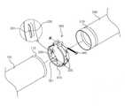
도 1은 종래의 보일러의 연도관 연결구조를 나타낸 분해 사시도이고, 도 2는 종래의 보일러의 연도관 연결구조를 나타낸 결합 정면도이다.1 is an exploded perspective view showing a flue tube connection structure of a conventional boiler, Figure 2 is a combined front view showing a flue tube connection structure of a conventional boiler.
도 1 및 도 2를 참조하면, 종래의 보일러의 연도관 연결구조는, 암 연도관(10) 일측에는 일부가 바깥쪽으로 벌어진 걸림테(11)이 형성되고, 수 연도관(20) 일측은 외주면 일부가 돌출된 돌출부(21)가 형성된다. 또한, 상기 암 연도관(10)의 걸림테(11)에 수 연도관(20)의 돌출부(21)가 걸림될 때까지 밀착되어 수 연도관(20)이 암 연도관(10)에 삽입되고, 암 연도관(10)의 걸림테(11) 및 수 연도관(20)의 돌출부(21)에 걸림되도록 고정밴드(30)에 만곡부(31)가 구비되어 암 연도관과 수 연도관이 고정밴드(30)의 체결수단(312)에 의해 연결된 상태로 고정될 수 있는 구조로 이루어진다.1 and 2, in the conventional flue pipe connection structure of the boiler, the
이러한 종래의 보일러의 연도관 연결구조는 암 연도관(10)의 걸림테(11)에 수 연도관(20)의 돌출부(21)가 걸림되도록 밀착된 상태에서 고정밴드(30)에 의해 상호간 연결된 상태로 결합되는 구조로서, 연도관의 길이조절이 불가능하고 최초 제작된 정해진 길이로만 연결하여 설치가 가능한 문제가 있다.The flue pipe connection structure of the conventional boiler is connected to each other by a
한편, 현재 보일러 설치 공사를 하고자 할 경우에는 가스안전공사가 정한 보일러의 설치 규격에 맞게 시공이 이루어져야만 가스안전공사로부터 사용 승인을 받을 수 있다. 하지만, 보일러가 설치될 각 현장은 건물의 시공 편차 및 구조의 변경 등 여러가지 현장 상황의 변수에 따라 사전에 정해진 보일러의 설치 규격과의 편차가 발생함에 따라 보일러를 설치하는 과정에서 연도관을 일부 확장하거나 축소시킨 상태로 시공이 이루어지고 있다.On the other hand, if you want to install the current boiler installation, the construction must be made in accordance with the boiler installation standards set by the Gas Safety Corporation can be approved for use from the gas safety construction. However, each site where the boiler is to be installed is partially extended to the flue pipe during the installation of the boiler due to the deviation from the predetermined installation specification of the boiler according to various site conditions such as the construction deviation of the building and the change of the structure. Construction is being done in a reduced or reduced state.
따라서, 상기 설명한 종래의 보일러의 연도관 연결구조에서는 상호 연결되는 연도관의 길이 조절이 불가능한 구조로서 실제 보일러가 설치될 각각의 공간에 대응하기 어려워 시공에 어려움이 있는 문제가 있다.Therefore, the above-described flue pipe connection structure of the conventional boiler is a structure that is not possible to adjust the length of the flue pipes are interconnected, there is a problem in that it is difficult to cope with each space where the actual boiler is to be installed.
본 발명의 목적은, 이러한 문제점을 해결하기 위한 것으로, 보일러 연도관을 설치하는데 있어 상호 연결되는 연도관을 보일러의 설치 위치에 따라 원하는 길이로 자유롭게 조절한 상태로 견고하게 고정시킬 수 있는 보일러의 연도관 연결구조를 제공하는데 있다.An object of the present invention is to solve such a problem, the flue of the boiler that can be firmly fixed in a state in which the flue pipes interconnected in the installation of the boiler flue pipes freely adjusted to the desired length according to the installation position of the boiler. To provide a pipe connection structure.
상기 과제를 달성하기 위한 본 발명의 기술적 사상의 일 실시예에 따른 보일러의 연도관 연결구조는, 복수의 연도관과 상기 복수의 연도관을 상호 연결시키는 고정밴드로 구성되는 보일러의 연도관 연결구조에 있어서, 상기 복수의 연도관은 일측에 위치되는 암 연도관, 타측에 위치되고 상기 암 연도관에 삽입되는 수 연도관으로 구성되고, 상기 암 연도관에는, 일측단이 외주면의 외경보다 큰 외경을 같도록 바깥쪽으로 벌어진 형태로 확장된 걸림테가 형성되고, 상기 수 연도관은, 상기 암 연도관에 삽입되기 위해 상기 암 연도관의 내경과 같거나 작은 외경의 외주면을 가지고, 상기 고정밴드에는, 상기 암 연도관과 상기 수 연도관을 감싸 듯 원형의 띠 형태를 가지도록 본체가 구성되고, 상기 본체의 외주면 일측에는 상기 암 연도관의 걸림테에 걸림되는 만곡부가 외측으로 절곡되도록 형성되고, 상기 본체의 외주면 타측에는 수 연도관의 외주면을 가압하도록 내측으로 절곡된 걸림핀이 형성되어, 상기 암 연도관에 수 연도관이 원하는 길이만큼 삽입된 상태에서 암 연도관의 걸림테 위치로 고정밴드의 만곡부가 걸림되고, 상기 고정밴드의 걸림핀이 수 연도관의 외주면을 가압한 상태로 상기 고정밴드의 체결수단을 통해 고정밴드를 조여주면, 상기 암 연도관과 수 연도관이 길이가 조절된 상태로 연결되어 고정될 수 있다.The flue pipe connection structure of the boiler according to an embodiment of the present invention for achieving the above object, the flue pipe connection structure of the boiler consisting of a plurality of flue pipes and a fixed band interconnecting the plurality of flue pipes. In the plurality of flue pipes are composed of a female flue pipe located on one side, the male flue pipes located on the other side and inserted into the female flue pipe, the female flue pipe, one end is larger than the outer diameter of the outer peripheral surface Hanging frame is formed to extend in the form of outwardly so that the same, the male flue pipe has an outer circumferential surface of the outer diameter equal to or less than the inner diameter of the female flue pipe for insertion into the female flue pipe, The main body is configured to have a circular band shape to surround the female flue pipe and the male flue pipe, and one side of the outer circumferential surface of the main body is caught by the hook of the female flue pipe. The curved portion is formed to be bent to the outside, the other side of the outer peripheral surface of the main body is formed with a locking pin bent inward to press the outer circumferential surface of the male flue pipe, the male flue pipe is inserted into the desired length as long as the desired length When the curved portion of the fixing band is locked to the position of the hook of the female flue pipe, and the locking pin of the fixing band tightens the fixing band through the fastening means of the fixing band while pressing the outer circumferential surface of the male flue pipe, the female flue The pipe and the water conduit can be connected and fixed in a controlled length.
또한, 상기 암 연도관의 걸림테는, 상기 암 연도관의 외주면 외경보다 큰 외경을 같도록 바깥쪽으로 벌어진 형태로 확장되되, 상기 걸림테의 끝단은 바깥쪽으로 말아진 형태로 형성될 수 있다.In addition, the hook frame of the female flue pipe, the outer diameter of the outer edge of the outer surface of the flue pipe extends in the form of spreading outward to the same, the end of the hook frame may be formed in the form rolled outward.
또한, 상기 수 연도관의 외주면에는, 일측에 상기 고정밴드의 걸림핀이 걸림될 수 있도록 외주면의 테두리를 따라 V홈이 형성될 수 있다.In addition, a V groove may be formed along the edge of the outer circumferential surface of the outer circumferential surface of the male flexible pipe so that the locking pin of the fixing band may be caught on one side thereof.
또한, 상기 수 연도관의 외주면에는, 일측에 상기 고정밴드의 걸림핀이 걸림될 수 있도록 외주면의 테두리를 따라 상기 걸림핀과 대응되는 위치에 관통된 타공홈이 형성될 수 있다.In addition, a perforated groove may be formed on the outer circumferential surface of the water softening pipe so as to penetrate at a position corresponding to the locking pin along an edge of the outer circumferential surface so that the locking pin of the fixing band may be locked on one side thereof.
또한, 상기 만곡부는, 상기 본체의 외주면 일측 테두리를 따라 외측으로 절곡 형성되되, 일부분이 일정 간격마다 돌출되도록 절곡되고, 다른 일부분은 돌출되지 않도록 절개된 개방부가 형성될 수 있다.In addition, the curved portion may be formed to be bent outwardly along one edge of the outer circumferential surface of the main body, a portion may be bent to protrude at a predetermined interval, and another portion may be formed to have an open portion cut out so as not to protrude.
또한, 상기 걸림핀은, 상기 고정밴드의 본체 외주면 내측으로 절곡되되, 일부분이 일정 간격마다 돌출되도록 절곡될 수 있다.In addition, the locking pin is bent into the outer peripheral surface of the main body of the fixing band, it may be bent so that a portion protrudes at a predetermined interval.
또한, 상기 걸림핀은, 상기 고정밴드의 본체 외주면 내측으로 절곡되되, 일부분이 절개된 상태로 절곡되어 관통홀이 형성된 형태일 수 있다.In addition, the locking pin may be bent into the outer circumferential surface of the main body of the fixing band, may be bent in a state in which a portion is cut may have a through-hole formed.
또한, 상기 걸림핀은, 상기 고정밴드의 본체 외주면 내측으로 절곡되되, 외주면의 내측 테두리를 따라 띠 형태로 돌출되도록 절곡될 수 있다.In addition, the locking pin is bent into the outer peripheral surface of the main body of the fixing band, it may be bent to protrude in the form of a band along the inner edge of the outer peripheral surface.
본 발명에 따른 보일러의 연도관 연결구조는, 암 연도관에 수 연도관이 삽입된 상태에서 암 연도관의 걸림테에 고정밴드의 만곡부가 결합되고, 고정밴드의 걸림핀이 수 연도관의 외주면을 가압하여 암 연도관과 수 연도관을 연결 고정시킬 수 있는 구조로서, 고정밴드의 걸림핀이 수 연도관의 외주면 어느 부분을 가압하더라도 견고하게 연결 고정될 수 있어, 연도관을 보일러의 설치 위치 및 현장의 상황에 대응하여 자유롭게 길이를 조절하여 설치할 수 있는 장점이 있다.The flue pipe connection structure of the boiler according to the present invention, the bent portion of the fixing band is coupled to the hook of the female flue pipe in the state that the male flue pipe is inserted into the female flue pipe, the locking pin of the fixing band is the outer peripheral surface of the male flue pipe It is a structure capable of connecting and fixing the female flue pipe and the male flue pipe by pressing the pressure.The locking pin of the fixing band can be firmly connected and fixed to any part of the outer circumferential surface of the male flue pipe, so that the flue pipe is installed at the boiler. And there is an advantage that can be installed to adjust the length freely in response to the situation of the site.
도 1은 종래의 보일러의 연도관 연결구조를 나타낸 분해 사시도.
도 2는 종래의 보일러의 연도관 연결구조를 나타낸 결합 정면도.
도 3은 본 발명의 일 실시예에 따른 보일러의 연도관 연결구조를 나타낸 분해 사시도.
도 4는 도 3의 보일러의 연도관 연결구조를 나타낸 결합 사시도.
도 5는 도 3의 보일러의 연도관 연결구조를 나타낸 분해 정면도.
도 6은 도 3의 보일러의 연도관 연결구조를 나타낸 결합 정면도.
도 7은 도 6의 보일러의 연도관 연결구조에서 연도관의 길이가 변경된 모습을 나타낸 결합 정면도.
도 8은 본 발명의 다른 실시예에 따른 보일러의 연도관 연결구조를 나타낸 분해 정면도.
도 9는 본 발명의 다른 실시예에 따른 보일러의 연도관 연결구조를 나타낸 분해 정면도.
도 10은 본 발명의 다른 실시예에 따른 고정밴드의 사시도.1 is an exploded perspective view showing a flue pipe connection structure of a conventional boiler.
Figure 2 is a combined front view showing a flue pipe connection structure of a conventional boiler.
Figure 3 is an exploded perspective view showing a flue pipe connection structure of the boiler according to an embodiment of the present invention.
Figure 4 is a perspective view showing a coupling pipe connection structure of the boiler of FIG.
5 is an exploded front view showing the flue pipe connection structure of the boiler of FIG.
6 is a front view showing a coupling pipe connection structure of the boiler of FIG.
7 is a combined front view showing a state in which the length of the flue pipe is changed in the flue pipe connection structure of the boiler of FIG.
Figure 8 is an exploded front view showing the flue pipe connection structure of the boiler according to another embodiment of the present invention.
Figure 9 is an exploded front view showing the flue pipe connection structure of the boiler according to another embodiment of the present invention.
10 is a perspective view of a fixing band according to another embodiment of the present invention.
본 발명과 본 발명의 동작상의 이점 및 본 발명의 실시에 의하여 달성되는 목적을 충분히 이해하기 위해서는 본 발명의 바람직한 실시예를 예시하는 첨부 도면 및 도면에 기재된 내용을 참조하여야 한다.DETAILED DESCRIPTION In order to fully understand the present invention, the operational advantages of the present invention, and the objects achieved by the practice of the present invention, reference should be made to the accompanying drawings which illustrate preferred embodiments of the present invention and the contents described in the drawings.
이하, 첨부한 도면을 참조하여 본 발명의 바람직한 실시예를 설명함으로써, 본 발명을 상세히 설명한다. 각 도면에 제시된 동일한 참조부호는 동일한 부재를 나타낸다.Hereinafter, exemplary embodiments of the present invention will be described in detail with reference to the accompanying drawings. Like reference numerals in the drawings denote like elements.
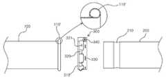
도 3은 본 발명의 일 실시예에 따른 보일러의 연도관 연결구조를 나타낸 분해 사시도이고, 도 4는 도 3의 보일러의 연도관 연결구조를 나타낸 결합 사시도이며, 도 5는 도 3의 보일러의 연도관 연결구조를 나타낸 분해 정면도이고, 도 6은 도 3의 보일러의 연도관 연결구조를 나타낸 결합 정면도이며, 도 7은 도 6의 보일러의 연도관 연결구조에서 연도관의 길이가 변경된 모습을 나타낸 결합 정면도이고, 도 8은 본 발명의 다른 실시예에 따른 보일러의 연도관 연결구조를 나타낸 분해 정면도이다.Figure 3 is an exploded perspective view showing a flue pipe connection structure of the boiler according to an embodiment of the present invention, Figure 4 is a combined perspective view showing a flue pipe connection structure of the boiler of Figure 3, Figure 5 is a flue of the boiler of Figure 3 6 is an exploded front view illustrating the pipe connection structure, and FIG. 6 is a combined front view showing the flue pipe connection structure of the boiler of FIG. 3, and FIG. 7 is a combination showing the state in which the length of the flue pipe is changed in the flue pipe connection structure of the boiler of FIG. 6. 8 is an exploded front view showing a flue pipe connection structure of a boiler according to another embodiment of the present invention.
도 3 내지 도 8을 참조하면, 본 발명의 일 실시예에 따른 보일러의 연도관 연결구조는 기본적으로, 복수의 연도관(100, 200)과 상기 복수의 연도관(100, 200)을 상호 연결시키는 고정밴드(300)로 구성되는 구조로 이루어질 수 있다. 또한, 상기 복수의 연도관(100, 200)은 각각 일측에 위치되는 암 연도관(100), 타측에 위치되고 상기 암 연도관(100)에 삽입되는 수 연도관(200)으로 구성될 수 있고, 본 발명에 따른 보일러의 연도관 연결구조는, 상기 수 연도관(200)이 상기 암 연도관(100)에 삽입되는 길이에 따라 최종적으로 설치되는 연도관의 길이를 결정할 수 있어, 보일러에 설치되는 연도관의 길이를 자유롭게 조절할 수 있게 된다.3 to 8, the flue pipe connection structure of the boiler according to an embodiment of the present invention, basically, a plurality of flue pipes (100, 200) and the plurality of flue pipes (100, 200) interconnected It may be made of a structure consisting of a
상기 암 연도관(100)에는, 일측단이 외주면의 외경보다 큰 외경을 같도록 바깥쪽으로 벌어진 형태로 확장된 걸림테(110)가 형성될 수 있다. 즉, 상기 걸림테(110)는 원통형으로 형성된 암 연도관(100)의 끝단 외경이 점차적으로 확장되는 형상으로서, 암 연도관(100)의 외주면보다 돌출되도록 형성될 수 있고, 또한, 외주면으로부터 확장되는 형상은 평평한 면을 가지는 평면 형태이거나 완만한 곡률을 가지도록 곡면으로 구성될 수 있다.The
한편, 상기 걸림테(110)는 상기 설명한 형태와 다른 형태로 구성될 수도 있다.On the other hand, the
도 8을 참조하면, 상기 암 연도관(100)의 걸림테(110')는, 상기 암 연도관(100)의 외주면 외경보다 큰 외경을 같도록 바깥쪽으로 벌어진 형태로 확장되되, 상기 걸림테(110')의 끝단은 바깥쪽으로 말아진 형태로 형성될 수 있다.Referring to FIG. 8, the
상기 걸림테(110')는 도면에 도시된 바와 같이, 상기 암 연도관(100)의 외주면의 끝단이 원형으로 말아진 형태로 형성될 수 있으며, 이는, 끝단이 날카롭게 노출되는 것을 방지하기 위해 외측으로 노출되는 부분을 곡면으로 마감한 것이다.As shown in the drawing, the
다음으로, 상기 수 연도관(200)은, 상기 암 연도관(100)에 삽입되기 위해 상기 암 연도관(100)의 내경과 같거나 작은 외경의 외주면을 가지도록 구성될 수 있다.Next, the
상기 수 연도관(200)의 외주면은 상기 암 연도관(100)에 삽입되고 암 연도관(100)의 내주면에 밀착되는 부분으로, 후술하는 상기 고정밴드(300)의 걸림핀(330)이 고정되는 부분이다. 즉, 상기 고정밴드(300)의 걸림핀(330)은 상기 수 연도관(200)의 외주면의 어느 곳이라도 고정될 수 있음을 의미한다.The outer circumferential surface of the
또한, 상기 수 연도관(200)의 외주면에는, 일측에 상기 고정밴드(300)의 걸림핀이(330) 걸림될 수 있도록 외주면의 테두리를 따라 V홈(210)이 형성될 수 있다.In addition, a
상기 V홈(210)은 상기 수 연도관(200)의 외주면 중 어느 한 부분의 테두리에 형성될 수 있으며, 상기 V홈(210)으로 고정밴드(300)의 걸림핀(330)이 걸림되어 수 연도관(200)이 고정될 수 있는 것으로, 걸림핀(330)의 형상과 대응되도록 형성될 수 있다.The V-
도 9는 본 발명의 다른 실시예에 따른 보일러의 연도관 연결구조를 나타낸 분해 정면도이다.Figure 9 is an exploded front view showing the flue tube connection structure of the boiler according to another embodiment of the present invention.
도 9를 참조하면, 상기 수 연도관(200)의 외주면에는, 일측에 상기 고정밴드(300)의 걸림핀(330)이 걸림될 수 있도록 외주면의 테두리를 따라 상기 걸림핀(330)과 대응되는 위치에 관통된 타공홈(220)이 형성될 수 있다. 즉, 상기 설명한 바와 같이, 고정밴드(300)의 걸림핀(330)이 걸림될 수 있도록 V홈(210)으로 구성될 수도 있으나, 경우에 따라, 걸림핀(330)의 위치 및 형상과 대응되도록 수 연도관(200)의 외주면에 관통된 형태의 타공홈(220)이 형성될 수도 있다.Referring to FIG. 9, the outer circumferential surface of the
따라서, 상기 고정밴드(300)의 걸림핀(330)은 수 연도관(200)의 외주면과 상기 V홈(210) 또는 타공홈(220) 중 어느 한 곳에 밀착되거나 걸림되어 수 연도관(200)을 고정시킬 수 있게 된다.Accordingly, the locking
다음으로, 상기 고정밴드(300)에는, 상기 암 연도관(100)과 상기 수 연도관(200)을 감싸 듯 원형의 띠 형태를 가지도록 본체(310)가 구성될 수 있다.Next, the
또한, 상기 본체(310)의 외주면 일측에는 상기 암 연도관(100)의 걸림테(110, 110')에 걸림되는 만곡부(320)가 외측으로 절곡되도록 형성될 수 있다.In addition, one side of the outer circumferential surface of the
또한, 상기 본체(310)의 외주면 타측에는 수 연도관(200)의 외주면, V홈(210) 또는 타공홈(220) 중 어느 한 곳을 가압하도록 내측으로 절곡된 걸림핀(330)이 형성될 수 있다.In addition, the other side of the outer circumferential surface of the
상기 고정밴드(300)의 만곡부(320)는, 상기 본체(310)의 외주면 일측 테두리를 따라 외측으로 절곡 형성될 수 있다. 즉, 상기 만곡부(320)는 상기 암 연도관(100)의 걸림테(110, 110')와 밀착되어 암 연도관(100)을 고정시키는 부분으로, 상기 걸림테(110, 110')의 형상에 대응되도록 형성될 수 있다.The
또한, 상기 만곡부(320)는 일부분이 일정 간격마다 돌출되도록 절곡되고, 다른 일부분은 돌출되지 않도록 절개된 개방부(321)가 형성될 수 있다. 즉, 만곡부(320)의 돌출된 부분은 걸림테(110, 110')와 밀착되어 고정력을 유지할 수 있는 최소한의 면적에만 형성될 수 있고, 그 외 부분은 절개된 개방부(321)로 형성하여 제작 단가를 낮출 수 있다.In addition, the
한편, 상기 걸림핀(330)은, 상기 고정밴드(300)의 본체(310) 외주면 내측으로 절곡될 수 있고, 일부분이 일정 간격마다 돌출되도록 절곡될 수 있다. 즉, 상기 걸림핀(330)은 수 연도관(200)의 외주면에 밀착되어 고정력을 유지할 수 있는 최소한의 면적에만 형성되어 제작 단가를 낮출 수 있다.Meanwhile, the locking
도 10은 본 발명의 다른 실시예에 따른 고정밴드의 사시도이다.10 is a perspective view of a fixing band according to another embodiment of the present invention.
도 10을 참조하면, 상기 걸림핀(330)은, 일부분이 절개된 상태로 절곡되어 관통홀(331)이 형성된 형태일 수 있다. 즉, 상기 걸림핀(330)은 본체(310) 외주면 내측으로 절곡되되, 일부가 '11'자 형상으로 절개된 관통홀(331)이 형성될 수 있다.Referring to FIG. 10, the locking
한편, 상기 걸림핀(330)은, 상기 고정밴드(300)의 본체(310) 외주면 내측으로 절곡될 수 있고, 외주면을 따라 띠 형태로 외주면 내측으로 돌출되도록 절곡 형성될 수도 있다.Meanwhile, the locking
또한, 상기 고정밴드(300)에는 상기 암 연도관(100)과 수 연도관(200)이 결합된 상태에서 이를 고정시키기 위해 일측 끝단에 나사결합되는 체결수단(340)이 구비될 수 있다.In addition, the fixing
이처럼, 상기 설명한 본 발명에 따른 보일러의 연도관 연결구조는, 상기 암 연도관(100)에 수 연도관(200)이 원하는 길이만큼 삽입된 상태에서 암 연도관(100)의 걸림테(110, 110') 위치로 고정밴드(300)의 만곡부(320)가 걸림되고, 상기 고정밴드(300)의 걸림핀(330)이 수 연도관(200)의 외주면을 가압한 상태로 상기 고정밴드(300)의 체결수단(340)을 통해 고정밴드(300)를 조여주면, 상기 암 연도관(100)과 수 연도관(200)이 길이가 조절된 상태로 연결되어 고정될 수 있다.Thus, the flue pipe connection structure of the boiler according to the present invention described above, the
이러한 상기 본 발명의 기술적 사상에 의한 일 실시예에 따른 보일러의 연도관 연결구조는, 암 연도관(100)에 수 연도관(200)이 삽입된 상태에서 암 연도관(100)의 걸림테(110)에 고정밴드(300)의 만곡부(320)가 결합되고, 고정밴드(300)의 걸림핀(330)이 수 연도관(200)의 외주면을 가압하여 암 연도관(100)과 수 연도관(200)을 연결 고정시킬 수 있는 구조로서, 고정밴드(300)의 걸림핀(330)이 수 연도관(200)의 외주면 어느 부분을 가압하더라도 견고하게 연결 고정될 수 있어, 연도관을 보일러의 설치위치 및 현장의 상황에 대응하여 자유롭게 길이를 조절하여 설치할 수 있는 장점이 있는 것이다.The flue pipe connection structure of the boiler according to the embodiment according to the technical idea of the present invention, the hook of the female flue pipe (100) in a state in which the
이상 설명한 바와 같이 도면과 명세서에서 최적 실시예가 개시되었다. 여기서 특정한 용어들이 사용되었으나, 이는 단지 본 발명을 설명하기 위한 목적에서 사용된 것이지 의미를 한정하거나 특허청구범위에 기재된 본 발명의 범위를 제한하기 위하여 사용된 것은 아니다. 그러므로 본 기술분야의 통상의 지식을 가진 자라면 이로부터 다양한 변형 및 균등한 타 실시예가 가능하다는 점을 이해할 것이다. 따라서, 본 발명의 진정한 기술적 보호범위는 첨부된 특허청구범위의 기술적 사상에 의해 정해져야 할 것이다.As described above, optimal embodiments have been disclosed in the drawings and the specification. Although specific terms have been used herein, they are used only for the purpose of describing the present invention and are not used to limit the meaning or the scope of the present invention described in the claims. Therefore, those skilled in the art will understand that various modifications and equivalent other embodiments are possible therefrom. Therefore, the true technical protection scope of the present invention will be defined by the technical spirit of the appended claims.
100: 암 연도관110, 110': 걸림테
200: 수 연도관210: V홈
220: 타공홈300: 고정밴드
310: 본체320: 만곡부
321: 개방부330: 걸림핀
331: 관통홀340: 체결수단100:
200: male flue pipe 210: V groove
220: perforated groove 300: fixed band
310: main body 320: curved portion
321: opening 330: locking pin
331: through hole 340: fastening means
Claims (8)
Translated fromKorean상기 복수의 연도관은 일측에 위치되는 암 연도관, 타측에 위치되고 상기 암 연도관에 삽입되는 수 연도관으로 구성되고,
상기 암 연도관에는, 일측단이 외주면의 외경보다 큰 외경을 같도록 바깥쪽으로 벌어진 형태로 확장된 걸림테가 형성되고,
상기 수 연도관은, 상기 암 연도관에 삽입되기 위해 상기 암 연도관의 내경과 같거나 작은 외경의 외주면을 가지고,
상기 고정밴드에는, 상기 암 연도관과 상기 수 연도관을 감싸 듯 원형의 띠 형태를 가지도록 본체가 구성되고, 상기 본체의 외주면 일측에는 상기 암 연도관의 걸림테에 걸림되는 만곡부가 외측으로 절곡되도록 형성되고, 상기 본체의 외주면 타측에는 수 연도관의 외주면을 가압하도록 내측으로 절곡된 걸림핀이 형성되어,
상기 암 연도관에 수 연도관이 원하는 길이만큼 삽입된 상태에서 암 연도관의 걸림테 위치로 고정밴드의 만곡부가 걸림되고, 상기 고정밴드의 걸림핀이 수 연도관의 외주면을 가압한 상태로 상기 고정밴드의 체결수단을 통해 고정밴드를 조여주면, 상기 암 연도관과 수 연도관이 길이가 조절된 상태로 연결되어 고정될 수 있는 것을 특징으로 하는 보일러의 연도관 연결구조.In the flue pipe connection structure of the boiler consisting of a plurality of flue pipes and a fixed band interconnecting the plurality of flue pipes,
The plurality of flue pipes are composed of a female flue pipe located on one side, a male flue pipe located on the other side and inserted into the female flue pipe,
The female flue pipe is formed with a hook frame that is extended in the form of spreading outward so that one end is equal to the outer diameter larger than the outer diameter of the outer peripheral surface,
The male flue conduit has an outer circumferential surface having an outer diameter equal to or smaller than the inner diameter of the female flue conduit for insertion into the female flue conduit,
The fixing band, the main body is configured to have a circular band shape as if the female flue pipe and the male flue pipe wrapped around, one side of the outer circumferential surface of the main body is bent outwardly bent to the hook frame of the female flue pipe It is formed so that, the other side of the outer peripheral surface of the main body is formed with a locking pin bent inward to press the outer peripheral surface of the male flexible pipe,
The bent portion of the fixing band is caught by the hook frame position of the female flue tube in the state where the male flue tube is inserted as long as the desired length, and the locking pin of the fixing band presses the outer circumferential surface of the male flue tube. When tightening the fixing band through the fastening means of the fixing band, the flue pipe connection structure of the boiler, characterized in that the female flue pipe and the male flue pipe can be connected and fixed in a controlled state.
상기 암 연도관의 걸림테는,
상기 암 연도관의 외주면 외경보다 큰 외경을 같도록 바깥쪽으로 벌어진 형태로 확장되되,
상기 걸림테의 끝단은 바깥쪽으로 말아진 형태로 형성되는 것을 특징으로 하는 보일러의 연도관 연결구조.The method of claim 1,
Hanging frame of the female flue pipe,
The outer circumferential surface of the female flue tube is expanded in the form of an outward so as to have a larger outer diameter,
The end of the hook frame is connected to the flue pipe of the boiler, characterized in that formed in the form rolled outward.
상기 수 연도관의 외주면에는,
일측에 상기 고정밴드의 걸림핀이 걸림될 수 있도록 외주면의 테두리를 따라 V홈이 형성되는 것을 특징으로 하는 보일러의 연도관 연결구조.The method of claim 1,
On the outer circumferential surface of the water pipe,
The flue pipe connection structure of the boiler, characterized in that the V groove is formed along the edge of the outer peripheral surface so that the locking pin of the fixing band on one side.
상기 수 연도관의 외주면에는,
일측에 상기 고정밴드의 걸림핀이 걸림될 수 있도록 외주면의 테두리를 따라 상기 걸림핀과 대응되는 위치에 관통된 타공홈이 형성되는 것을 특징으로 하는 보일러의 연도관 연결구조.The method of claim 1,
On the outer circumferential surface of the water pipe,
Flue pipe connection structure of the boiler characterized in that the perforated grooves are formed in a position corresponding to the locking pins along the edge of the outer peripheral surface so that the locking pins of the fixing band can be locked on one side.
상기 만곡부는,
상기 본체의 외주면 일측 테두리를 따라 외측으로 절곡 형성되되,
일부분이 일정 간격마다 돌출되도록 절곡되고, 다른 일부분은 돌출되지 않도록 절개된 개방부가 형성되는 것을 특징으로 하는 보일러의 연도관 연결구조.The method of claim 1,
The curved portion,
It is formed to be bent outward along one side of the outer peripheral surface of the main body,
A flue tube connection structure of a boiler, wherein a part is bent so as to protrude at regular intervals and the other part is formed with an incision open so as not to protrude.
상기 걸림핀은,
상기 고정밴드의 본체 외주면 내측으로 절곡되되,
일부분이 일정 간격마다 돌출되도록 절곡되는 것을 특징으로 하는 보일러의 연도관 연결구조.The method of claim 1,
The locking pin,
Bent into the outer peripheral surface of the main body of the fixing band,
Flue pipe connection structure, characterized in that the portion is bent so as to project at regular intervals.
상기 걸림핀은,
상기 고정밴드의 본체 외주면 내측으로 절곡되되,
일부분이 절개된 상태로 절곡되어 관통홀이 형성된 형태인 것을 특징으로 하는 보일러의 연도관 연결구조.The method of claim 1,
The locking pin,
Bent into the outer peripheral surface of the main body of the fixing band,
Flue pipe connection structure of the boiler characterized in that the portion is bent in a cut state form a through-hole.
상기 걸림핀은,
상기 고정밴드의 외주면 내측으로 절곡되되,
외주면의 내측 테두리를 따라 띠 형태로 돌출되도록 절곡되는 것을 특징으로 하는 보일러의 연도관 연결구조.The method of claim 1,
The locking pin,
Bent into the outer circumferential surface of the fixing band,
Flue pipe connection structure of the boiler characterized in that bent to protrude in the form of a band along the inner edge of the outer peripheral surface.
Priority Applications (1)
| Application Number | Priority Date | Filing Date | Title |
|---|---|---|---|
| KR1020180056081AKR20190131335A (en) | 2018-05-16 | 2018-05-16 | Smoke pipe connecting structure) |
Applications Claiming Priority (1)
| Application Number | Priority Date | Filing Date | Title |
|---|---|---|---|
| KR1020180056081AKR20190131335A (en) | 2018-05-16 | 2018-05-16 | Smoke pipe connecting structure) |
Publications (1)
| Publication Number | Publication Date |
|---|---|
| KR20190131335Atrue KR20190131335A (en) | 2019-11-26 |
Family
ID=68731568
Family Applications (1)
| Application Number | Title | Priority Date | Filing Date |
|---|---|---|---|
| KR1020180056081AAbandonedKR20190131335A (en) | 2018-05-16 | 2018-05-16 | Smoke pipe connecting structure) |
Country Status (1)
| Country | Link |
|---|---|
| KR (1) | KR20190131335A (en) |
Cited By (1)
| Publication number | Priority date | Publication date | Assignee | Title |
|---|---|---|---|---|
| KR20220032199A (en)* | 2020-09-07 | 2022-03-15 | 씨에스산업 주식회사 | Connecting structure of exhaust pipe for boiler |
- 2018
- 2018-05-16KRKR1020180056081Apatent/KR20190131335A/ennot_activeAbandoned
Cited By (1)
| Publication number | Priority date | Publication date | Assignee | Title |
|---|---|---|---|---|
| KR20220032199A (en)* | 2020-09-07 | 2022-03-15 | 씨에스산업 주식회사 | Connecting structure of exhaust pipe for boiler |
Similar Documents
| Publication | Publication Date | Title |
|---|---|---|
| US5815892A (en) | Profile clamp | |
| JP5222305B2 (en) | Stepped ball joint pipe clamp and its pre-installed components | |
| US3933377A (en) | Hanger assembly for pipe | |
| AU2007237326B2 (en) | Tightenable band clamp | |
| IL24624A (en) | Clamping element for connecting or supporting pipes | |
| CZ372399A3 (en) | Tube sleeve | |
| US20190063644A1 (en) | Lock band and method of manufacturing | |
| US5819435A (en) | Telescopic duct connection with dimples | |
| KR101128257B1 (en) | Sprinkler system assembled with a single unit of an elbow and a flexible joint for an apartment | |
| KR20190131335A (en) | Smoke pipe connecting structure) | |
| US6123366A (en) | Pipe reinforcing device | |
| KR100881351B1 (en) | Pipe with expansion pipe end made of separation prevention structure | |
| CN114746687A (en) | hose clamp | |
| KR0117170Y1 (en) | Flexible piping device for sprinkler | |
| EP4241001B1 (en) | Apparatus for supporting an object | |
| US5470112A (en) | Adjustable coupling ring | |
| KR100836905B1 (en) | Sewer pipe connection | |
| JP4732772B2 (en) | Pipe joint fixing structure | |
| KR102180711B1 (en) | Multi function joint set for pipe | |
| KR200254112Y1 (en) | Pipe folds connection device for spring kler | |
| KR102700794B1 (en) | Groove coupling assembly for pipe joints of different diameters | |
| KR200306564Y1 (en) | Joint for Bellows Pipe having Inside Tube for one’s Caliber Reduction Control | |
| KR20180003122U (en) | Locking Device for Preventing Connecter from Loose | |
| CN215981285U (en) | Air duct | |
| KR200201938Y1 (en) | A |
Legal Events
| Date | Code | Title | Description |
|---|---|---|---|
| A201 | Request for examination | ||
| PA0109 | Patent application | Patent event code:PA01091R01D Comment text:Patent Application Patent event date:20180516 | |
| PA0201 | Request for examination | ||
| E902 | Notification of reason for refusal | ||
| PE0902 | Notice of grounds for rejection | Comment text:Notification of reason for refusal Patent event date:20190710 Patent event code:PE09021S01D | |
| PG1501 | Laying open of application | ||
| E701 | Decision to grant or registration of patent right | ||
| PE0701 | Decision of registration | Patent event code:PE07011S01D Comment text:Decision to Grant Registration Patent event date:20200123 | |
| PC1904 | Unpaid initial registration fee |