KR20190126445A - Multiview Backlights, Displays, and Methods Using Active Emitters - Google Patents
Multiview Backlights, Displays, and Methods Using Active EmittersDownload PDFInfo
- Publication number
- KR20190126445A KR20190126445AKR1020197032136AKR20197032136AKR20190126445AKR 20190126445 AKR20190126445 AKR 20190126445AKR 1020197032136 AKR1020197032136 AKR 1020197032136AKR 20197032136 AKR20197032136 AKR 20197032136AKR 20190126445 AKR20190126445 AKR 20190126445A
- Authority
- KR
- South Korea
- Prior art keywords
- light
- multiview
- array
- active
- emitters
- Prior art date
- Legal status (The legal status is an assumption and is not a legal conclusion. Google has not performed a legal analysis and makes no representation as to the accuracy of the status listed.)
- Granted
Links
Images


Classifications
- G—PHYSICS
- G09—EDUCATION; CRYPTOGRAPHY; DISPLAY; ADVERTISING; SEALS
- G09G—ARRANGEMENTS OR CIRCUITS FOR CONTROL OF INDICATING DEVICES USING STATIC MEANS TO PRESENT VARIABLE INFORMATION
- G09G3/00—Control arrangements or circuits, of interest only in connection with visual indicators other than cathode-ray tubes
- G09G3/20—Control arrangements or circuits, of interest only in connection with visual indicators other than cathode-ray tubes for presentation of an assembly of a number of characters, e.g. a page, by composing the assembly by combination of individual elements arranged in a matrix no fixed position being assigned to or needed to be assigned to the individual characters or partial characters
- G09G3/34—Control arrangements or circuits, of interest only in connection with visual indicators other than cathode-ray tubes for presentation of an assembly of a number of characters, e.g. a page, by composing the assembly by combination of individual elements arranged in a matrix no fixed position being assigned to or needed to be assigned to the individual characters or partial characters by control of light from an independent source
- G09G3/3406—Control of illumination source
- G09G3/342—Control of illumination source using several illumination sources separately controlled corresponding to different display panel areas, e.g. along one dimension such as lines
- G02B27/22—
- G—PHYSICS
- G02—OPTICS
- G02B—OPTICAL ELEMENTS, SYSTEMS OR APPARATUS
- G02B30/00—Optical systems or apparatus for producing three-dimensional [3D] effects, e.g. stereoscopic images
- G02B30/20—Optical systems or apparatus for producing three-dimensional [3D] effects, e.g. stereoscopic images by providing first and second parallax images to an observer's left and right eyes
- G02B30/26—Optical systems or apparatus for producing three-dimensional [3D] effects, e.g. stereoscopic images by providing first and second parallax images to an observer's left and right eyes of the autostereoscopic type
- G02B30/33—Optical systems or apparatus for producing three-dimensional [3D] effects, e.g. stereoscopic images by providing first and second parallax images to an observer's left and right eyes of the autostereoscopic type involving directional light or back-light sources
- G—PHYSICS
- G02—OPTICS
- G02B—OPTICAL ELEMENTS, SYSTEMS OR APPARATUS
- G02B6/00—Light guides; Structural details of arrangements comprising light guides and other optical elements, e.g. couplings
- G02B6/0001—Light guides; Structural details of arrangements comprising light guides and other optical elements, e.g. couplings specially adapted for lighting devices or systems
- G02B6/0011—Light guides; Structural details of arrangements comprising light guides and other optical elements, e.g. couplings specially adapted for lighting devices or systems the light guides being planar or of plate-like form
- G02B6/0066—Light guides; Structural details of arrangements comprising light guides and other optical elements, e.g. couplings specially adapted for lighting devices or systems the light guides being planar or of plate-like form characterised by the light source being coupled to the light guide
- G02B6/0068—Arrangements of plural sources, e.g. multi-colour light sources
- G—PHYSICS
- G02—OPTICS
- G02B—OPTICAL ELEMENTS, SYSTEMS OR APPARATUS
- G02B6/00—Light guides; Structural details of arrangements comprising light guides and other optical elements, e.g. couplings
- G02B6/0001—Light guides; Structural details of arrangements comprising light guides and other optical elements, e.g. couplings specially adapted for lighting devices or systems
- G02B6/0011—Light guides; Structural details of arrangements comprising light guides and other optical elements, e.g. couplings specially adapted for lighting devices or systems the light guides being planar or of plate-like form
- G02B6/0066—Light guides; Structural details of arrangements comprising light guides and other optical elements, e.g. couplings specially adapted for lighting devices or systems the light guides being planar or of plate-like form characterised by the light source being coupled to the light guide
- G02B6/0073—Light emitting diode [LED]
- G—PHYSICS
- G02—OPTICS
- G02B—OPTICAL ELEMENTS, SYSTEMS OR APPARATUS
- G02B6/00—Light guides; Structural details of arrangements comprising light guides and other optical elements, e.g. couplings
- G02B6/10—Light guides; Structural details of arrangements comprising light guides and other optical elements, e.g. couplings of the optical waveguide type
- G02B6/12—Light guides; Structural details of arrangements comprising light guides and other optical elements, e.g. couplings of the optical waveguide type of the integrated circuit kind
- G02B6/122—Basic optical elements, e.g. light-guiding paths
- G—PHYSICS
- G09—EDUCATION; CRYPTOGRAPHY; DISPLAY; ADVERTISING; SEALS
- G09G—ARRANGEMENTS OR CIRCUITS FOR CONTROL OF INDICATING DEVICES USING STATIC MEANS TO PRESENT VARIABLE INFORMATION
- G09G3/00—Control arrangements or circuits, of interest only in connection with visual indicators other than cathode-ray tubes
- G09G3/20—Control arrangements or circuits, of interest only in connection with visual indicators other than cathode-ray tubes for presentation of an assembly of a number of characters, e.g. a page, by composing the assembly by combination of individual elements arranged in a matrix no fixed position being assigned to or needed to be assigned to the individual characters or partial characters
- G09G3/34—Control arrangements or circuits, of interest only in connection with visual indicators other than cathode-ray tubes for presentation of an assembly of a number of characters, e.g. a page, by composing the assembly by combination of individual elements arranged in a matrix no fixed position being assigned to or needed to be assigned to the individual characters or partial characters by control of light from an independent source
- G09G3/3406—Control of illumination source
- G09G3/3413—Details of control of colour illumination sources
- G—PHYSICS
- G09—EDUCATION; CRYPTOGRAPHY; DISPLAY; ADVERTISING; SEALS
- G09G—ARRANGEMENTS OR CIRCUITS FOR CONTROL OF INDICATING DEVICES USING STATIC MEANS TO PRESENT VARIABLE INFORMATION
- G09G3/00—Control arrangements or circuits, of interest only in connection with visual indicators other than cathode-ray tubes
- G09G3/20—Control arrangements or circuits, of interest only in connection with visual indicators other than cathode-ray tubes for presentation of an assembly of a number of characters, e.g. a page, by composing the assembly by combination of individual elements arranged in a matrix no fixed position being assigned to or needed to be assigned to the individual characters or partial characters
- G09G3/34—Control arrangements or circuits, of interest only in connection with visual indicators other than cathode-ray tubes for presentation of an assembly of a number of characters, e.g. a page, by composing the assembly by combination of individual elements arranged in a matrix no fixed position being assigned to or needed to be assigned to the individual characters or partial characters by control of light from an independent source
- G09G3/3433—Control arrangements or circuits, of interest only in connection with visual indicators other than cathode-ray tubes for presentation of an assembly of a number of characters, e.g. a page, by composing the assembly by combination of individual elements arranged in a matrix no fixed position being assigned to or needed to be assigned to the individual characters or partial characters by control of light from an independent source using light modulating elements actuated by an electric field and being other than liquid crystal devices and electrochromic devices
- G09G3/3473—Control arrangements or circuits, of interest only in connection with visual indicators other than cathode-ray tubes for presentation of an assembly of a number of characters, e.g. a page, by composing the assembly by combination of individual elements arranged in a matrix no fixed position being assigned to or needed to be assigned to the individual characters or partial characters by control of light from an independent source using light modulating elements actuated by an electric field and being other than liquid crystal devices and electrochromic devices based on light coupled out of a light guide, e.g. due to scattering, by contracting the light guide with external means
- H—ELECTRICITY
- H04—ELECTRIC COMMUNICATION TECHNIQUE
- H04N—PICTORIAL COMMUNICATION, e.g. TELEVISION
- H04N13/00—Stereoscopic video systems; Multi-view video systems; Details thereof
- H04N13/30—Image reproducers
- H—ELECTRICITY
- H04—ELECTRIC COMMUNICATION TECHNIQUE
- H04N—PICTORIAL COMMUNICATION, e.g. TELEVISION
- H04N13/00—Stereoscopic video systems; Multi-view video systems; Details thereof
- H04N13/30—Image reproducers
- H04N13/302—Image reproducers for viewing without the aid of special glasses, i.e. using autostereoscopic displays
- H04N13/31—Image reproducers for viewing without the aid of special glasses, i.e. using autostereoscopic displays using parallax barriers
- H04N13/315—Image reproducers for viewing without the aid of special glasses, i.e. using autostereoscopic displays using parallax barriers the parallax barriers being time-variant
- H—ELECTRICITY
- H04—ELECTRIC COMMUNICATION TECHNIQUE
- H04N—PICTORIAL COMMUNICATION, e.g. TELEVISION
- H04N13/00—Stereoscopic video systems; Multi-view video systems; Details thereof
- H04N13/30—Image reproducers
- H04N13/302—Image reproducers for viewing without the aid of special glasses, i.e. using autostereoscopic displays
- H04N13/32—Image reproducers for viewing without the aid of special glasses, i.e. using autostereoscopic displays using arrays of controllable light sources; using moving apertures or moving light sources
- H—ELECTRICITY
- H04—ELECTRIC COMMUNICATION TECHNIQUE
- H04N—PICTORIAL COMMUNICATION, e.g. TELEVISION
- H04N13/00—Stereoscopic video systems; Multi-view video systems; Details thereof
- H04N13/30—Image reproducers
- H04N13/302—Image reproducers for viewing without the aid of special glasses, i.e. using autostereoscopic displays
- H04N13/322—Image reproducers for viewing without the aid of special glasses, i.e. using autostereoscopic displays using varifocal lenses or mirrors
- H—ELECTRICITY
- H04—ELECTRIC COMMUNICATION TECHNIQUE
- H04N—PICTORIAL COMMUNICATION, e.g. TELEVISION
- H04N13/00—Stereoscopic video systems; Multi-view video systems; Details thereof
- H04N13/30—Image reproducers
- H04N13/324—Colour aspects
- H—ELECTRICITY
- H04—ELECTRIC COMMUNICATION TECHNIQUE
- H04N—PICTORIAL COMMUNICATION, e.g. TELEVISION
- H04N13/00—Stereoscopic video systems; Multi-view video systems; Details thereof
- H04N13/30—Image reproducers
- H04N13/349—Multi-view displays for displaying three or more geometrical viewpoints without viewer tracking
- H04N13/351—Multi-view displays for displaying three or more geometrical viewpoints without viewer tracking for displaying simultaneously
- H—ELECTRICITY
- H04—ELECTRIC COMMUNICATION TECHNIQUE
- H04N—PICTORIAL COMMUNICATION, e.g. TELEVISION
- H04N13/00—Stereoscopic video systems; Multi-view video systems; Details thereof
- H04N13/30—Image reproducers
- H04N13/349—Multi-view displays for displaying three or more geometrical viewpoints without viewer tracking
- H04N13/354—Multi-view displays for displaying three or more geometrical viewpoints without viewer tracking for displaying sequentially
- H—ELECTRICITY
- H04—ELECTRIC COMMUNICATION TECHNIQUE
- H04N—PICTORIAL COMMUNICATION, e.g. TELEVISION
- H04N13/00—Stereoscopic video systems; Multi-view video systems; Details thereof
- H04N13/30—Image reproducers
- H04N13/356—Image reproducers having separate monoscopic and stereoscopic modes
- H—ELECTRICITY
- H04—ELECTRIC COMMUNICATION TECHNIQUE
- H04N—PICTORIAL COMMUNICATION, e.g. TELEVISION
- H04N13/00—Stereoscopic video systems; Multi-view video systems; Details thereof
- H04N13/30—Image reproducers
- H04N13/356—Image reproducers having separate monoscopic and stereoscopic modes
- H04N13/359—Switching between monoscopic and stereoscopic modes
- H—ELECTRICITY
- H04—ELECTRIC COMMUNICATION TECHNIQUE
- H04N—PICTORIAL COMMUNICATION, e.g. TELEVISION
- H04N13/00—Stereoscopic video systems; Multi-view video systems; Details thereof
- H04N13/30—Image reproducers
- H04N13/398—Synchronisation thereof; Control thereof
- G—PHYSICS
- G09—EDUCATION; CRYPTOGRAPHY; DISPLAY; ADVERTISING; SEALS
- G09G—ARRANGEMENTS OR CIRCUITS FOR CONTROL OF INDICATING DEVICES USING STATIC MEANS TO PRESENT VARIABLE INFORMATION
- G09G2320/00—Control of display operating conditions
- G09G2320/02—Improving the quality of display appearance
- G09G2320/0242—Compensation of deficiencies in the appearance of colours
- G—PHYSICS
- G09—EDUCATION; CRYPTOGRAPHY; DISPLAY; ADVERTISING; SEALS
- G09G—ARRANGEMENTS OR CIRCUITS FOR CONTROL OF INDICATING DEVICES USING STATIC MEANS TO PRESENT VARIABLE INFORMATION
- G09G2320/00—Control of display operating conditions
- G09G2320/02—Improving the quality of display appearance
- G09G2320/028—Improving the quality of display appearance by changing the viewing angle properties, e.g. widening the viewing angle, adapting the viewing angle to the view direction
Landscapes
- Engineering & Computer Science (AREA)
- Physics & Mathematics (AREA)
- Multimedia (AREA)
- Signal Processing (AREA)
- General Physics & Mathematics (AREA)
- Optics & Photonics (AREA)
- Theoretical Computer Science (AREA)
- Computer Hardware Design (AREA)
- Microelectronics & Electronic Packaging (AREA)
- Liquid Crystal (AREA)
- Control Of Indicators Other Than Cathode Ray Tubes (AREA)
- Planar Illumination Modules (AREA)
- Devices For Indicating Variable Information By Combining Individual Elements (AREA)
- Liquid Crystal Display Device Control (AREA)
- Electroluminescent Light Sources (AREA)
- Testing, Inspecting, Measuring Of Stereoscopic Televisions And Televisions (AREA)
Abstract
Translated fromKoreanDescription
Translated fromKorean전자 디스플레이는 다양한 장치 및 제품의 사용자에게 정보를 전달하기 위한 매우 보편적인 매체이다. 가장 일반적으로 사용되는 전자 디스플레이에는 음극선관(CRT), 플라즈마 표시 패널(PDP), 액정 디스플레이(LCD), 전계 발광 디스플레이(EL), 유기 발광 다이오드(OLED) 및 액티브 매트릭스 OLED (AMOLED) 디스플레이, 전기 영동 디스플레이(EP), 및 전기기계 또는 전기유체 광 변조(디지털 미소반사 장치 및 전기 습윤 디스플레이 등)를 사용하는 다양한 디스플레이를 포함한다. 일반적으로, 전자 디스플레이는 액티브 디스플레이(즉, 광을 방출하는 디스플레이) 또는 수동 디스플레이(즉, 다른 소스에 의해 제공되는 광을 변조하는 디스플레이)로 분류될 수 있다. 액티브 디스플레이의 가장 명확한 예로는 CRT, PDP 및 OLED/AMOLED가 있다. 발광 측면을 고려하면 LCD 및 EP 디스플레이는 통상적으로 수동 디스플레이로 분류된다. 수동 디스플레이는 종종 내재적으로 낮은 소비전력을 포함하면서도 이에 제한되지 않는 매력적인 성능 특성을 나타내는 반면, 발광 능력이 없어 많은 실제 응용에서 용도가 다소 제한적임을 알 수 있다.Electronic displays are a very common medium for conveying information to users of various devices and products. The most commonly used electronic displays include cathode ray tube (CRT), plasma display panel (PDP), liquid crystal display (LCD), electroluminescent display (EL), organic light emitting diode (OLED) and active matrix OLED (AMOLED) displays, electrical Electrophoretic displays (EP), and various displays using electromechanical or electrofluidic light modulation (such as digital microreflective devices and electrowetting displays, etc.). In general, electronic displays may be classified as either active displays (ie, displays emitting light) or passive displays (ie, displays modulating light provided by other sources). The most obvious examples of active displays are CRTs, PDPs, and OLED / AMOLEDs. Considering the light emitting side, LCD and EP displays are usually classified as passive displays. Passive displays often exhibit attractive performance characteristics that include, but are not limited to, inherently low power consumption, while the lack of luminescence capability indicates that their use is somewhat limited in many practical applications.
발광과 관련된 수동 디스플레이의 한계를 극복하기 위해, 많은 수동 디스플레이가 외부 광원과 결합된다. 상기 결합된 광원은 이러한 다른 수동 디스플레이가 광을 방출하여 실질적으로 액티브 디스플레이로 기능하도록 할 수 있다. 상기 결합된 광원의 예로는 백라이트가 있다. 백라이트는 다른 수동 디스플레이 뒤에 배치되어 광원(종종 패널 백라이트)으로 작용하여 상기 수동 디스플레이를 조명할 수 있다. 예컨대, 백라이트는 LCD 또는 EP 디스플레이에 결합될 수 있다. 상기 백라이트는 상기 LCD 또는 EP 디스플레이를 관통하는 광을 방출한다. 상기 방출된 광은 상기 LCD 또는 EP 디스플레이에 의해 변조된 후, 상기 변조된 광은 결국 상기 LCD 또는 EP 디스플레이로부터 방출된다. 백라이트는 백색광을 방출하도록 구성되기도 한다. 이후 상기 백색광을 디스플레이에서 사용되는 다양한 색상으로 변환하기 위해 색상 필터가 사용된다. 예컨대, 상기 색상 필터는 상기 LCD 또는 EP 디스플레이의 출력부에 배치되거나(덜 일반적임) 상기 백라이트와 상기 LCD 또는 EP 디스플레이 사이에 배치될 수 있다. 또는, 원색 등 상이한 색상을 사용하는 디스플레이의 필드 순차(field-sequential) 조명에 의해 다양한 색상을 구현할 수 있다.To overcome the limitations of passive displays associated with luminescence, many passive displays are combined with external light sources. The combined light source can cause these other passive displays to emit light to function substantially as an active display. An example of such a combined light source is a backlight. The backlight can be placed behind another passive display to act as a light source (often a panel backlight) to illuminate the passive display. For example, the backlight can be coupled to an LCD or EP display. The backlight emits light that passes through the LCD or EP display. After the emitted light is modulated by the LCD or EP display, the modulated light is eventually emitted from the LCD or EP display. The backlight may also be configured to emit white light. A color filter is then used to convert the white light into the various colors used in the display. For example, the color filter may be arranged at the output of the LCD or EP display (less common) or between the backlight and the LCD or EP display. Alternatively, various colors may be implemented by field-sequential illumination of a display using different colors such as primary colors.
본 명세서에 기술된 원리에 따른 예 및 실시예의 다양한 특징들은 첨부 도면과 관련하여 취해진 다음의 상세한 설명을 참조하여 더 용이하게 이해될 수 있다. 이때, 동일한 도면 부호는 동일한 구조적 요소를 나타낸다.
도 1a는 본 명세서에 설명된 원리에 일치하는 실시예에 따른 일 예로서의 멀티뷰 디스플레이를 나타내는 사시도.
도 1b는 본 명세서에 설명된 원리에 일치하는 실시예에 따른 일 예로서의 멀티뷰 디스플레이의 뷰 방향에 대응하는 특정 주요각 방향을 갖는 광빔의 각도 성분들을 도시하는 그래프.
도 2a는 본 명세서에 설명된 원리에 일치하는 실시예에 따른 일 예로서의 멀티뷰 백라이트를 도시하는 단면도.
도 2b는 본 명세서에 설명된 원리에 일치하는 실시예에 따른 일 예로서의 멀티뷰 백라이트를 도시하는 평면도.
도 2c는 본 명세서에 설명된 원리에 일치하는 실시예에 따른 일 예로서의 멀티뷰 백라이트를 도시하는 평면도.
도 3a는 본 명세서에 설명된 원리에 일치하는 실시예에 따른 일 예로서의 멀티뷰 백라이트를 도시하는 평면도.
도 3b는 본 명세서에 설명된 원리에 일치하는 실시예에 따른 일 예로서의 멀티뷰 픽셀의 일부 및 도 3a의 멀티뷰 백라이트의 일부를 도시하는 평면도.
도 4는 본 명세서에 설명된 원리에 일치하는 실시예에 따른 일 예로서의 광각 백라이트를 포함하는 멀티뷰 백라이트를 도시하는 단면도.
도 5는 본 명세서에 설명된 원리에 일치하는 실시예에 따른 일 예로서의 멀티뷰 디스플레이를 도시하는 블록도.
도 6은 본 명세서에 설명된 원리에 일치하는 실시예에 따른 멀티뷰 디스플레이 작동 방법을 도시하는 흐름도.
일부 예 및 실시예는 전술한 도면에 예시된 특징들에 부가되거나 이들을 대신하는 특징들 중 하나인 기타 특징들을 갖는다. 이하 상기 도면들을 참조하여 이러한 특징 및 기타 특징들 상세히 설명한다.Various features of examples and embodiments in accordance with the principles described herein may be more readily understood with reference to the following detailed description taken in conjunction with the accompanying drawings. At this time, the same reference numerals represent the same structural elements.
1A is a perspective view illustrating an example multiview display in accordance with an embodiment consistent with the principles described herein.
1B is a graph showing the angular components of a light beam having a particular major angular direction corresponding to the viewing direction of an example multiview display according to an embodiment consistent with the principles described herein.
2A is a cross-sectional view illustrating an example multiview backlight in accordance with an embodiment consistent with the principles described herein.
2B is a plan view illustrating an example multiview backlight in accordance with an embodiment consistent with the principles described herein;
2C is a plan view illustrating an example multiview backlight in accordance with an embodiment consistent with the principles described herein;
3A is a plan view illustrating an example multiview backlight in accordance with an embodiment consistent with the principles described herein;
3B is a plan view illustrating a portion of a multiview pixel as an example and a portion of the multiview backlight of FIG. 3A in accordance with an embodiment consistent with the principles described herein.
4 is a cross-sectional view illustrating a multiview backlight including an example wide-angle backlight according to an embodiment consistent with the principles described herein.
5 is a block diagram illustrating an example multiview display in accordance with an embodiment consistent with the principles described herein.
6 is a flow chart illustrating a method of operating a multiview display according to an embodiment consistent with the principles described herein.
Some examples and embodiments have other features that are one of the features added to or in place of the features illustrated in the foregoing figures. Hereinafter, these and other features will be described in detail with reference to the drawings.
본 명세서에 설명된 원리에 따른 예 및 실시예는 전자 디스플레이에 적용되는 액티브 이미터들을 사용하는 백라이트를 제공한다. 본 명세서의 원리에 일치하는 다양한 실시예는 멀티뷰 백라이트를 제공한다. 상기 멀티뷰 백라이트는 빛을 방출하는 액티브 이미터들을 포함한다. 상기 액티브 이미터들은 마이크로 발광 다이오드(μLED) 또는 유기 마이크로 발광 다이오드(OLED)를 포함한다. 상기 액티브 이미터들은 백색광 또는 색상을 갖는 광을 발광하도록 구성될 수 있다. 일부 실시예에 따르면, 상기 액티브 이미터들은 색록을 줄이거나 억제하도록 인접한 액티브 이미터들로부터 부분적으로 오프셋될 수 있다.Examples and embodiments in accordance with the principles described herein provide a backlight using active emitters applied to an electronic display. Various embodiments consistent with the principles herein provide a multiview backlight. The multiview backlight includes active emitters that emit light. The active emitters include micro light emitting diodes (μLEDs) or organic micro light emitting diodes (OLEDs). The active emitters can be configured to emit white light or light having color. According to some embodiments, the active emitters may be partially offset from adjacent active emitters to reduce or suppress color block.
본 명세서에서 ‘2차원 디스플레이’ 또는 ‘2D 디스플레이’는 영상을 보는 방향에 관계없이(즉, 사전에 정의된 시야각 또는 2D 디스플레이의 범위 내에서) 실질적으로 동일한 영상의 장면을 제공하도록 구성된 디스플레이로 정의된다. 2D 디스플레이의 예로는 스마트폰 및 컴퓨터 모니터에서 보이는 종래의 액정 디스플레이(LCD)가 있다. 반면, 본 명세서에서 ‘멀티뷰 디스플레이’는 멀티뷰 영상의 상이한 뷰들을 상이한 뷰 방향들로 또는 상이한 뷰 방향들로부터 제공하도록 구성된 전자 디스플레이 또는 디스플레이 시스템으로 정의된다. 특히, 상기 상이한 뷰들은 멀티뷰 영상의 장면 또는 객체의 상이한 투시 뷰들을 나타낼 수 있다. 본 명세서에 설명된 멀티뷰 영상들의 표시에 적용 가능한 멀티뷰 백라이트 및 멀티뷰 디스플레이의 용도에는 이동 전화(스마트폰 등), 시계, 태블릿 컴퓨터, 모바일 컴퓨터(노트북 컴퓨터 등), 개인용 컴퓨터, 컴퓨터 모니터, 자동차 디스플레이 콘솔, 카메라 디스플레이, 및 기타 다양한 이동식 및 실질적으로 비-이동식 디스플레이 응용 및 장치를 포함한다.In the present specification, 'two-dimensional display' or '2D display' is defined as a display configured to provide a scene of substantially the same image regardless of the direction of viewing the image (ie, within a predefined viewing angle or a range of the 2D display). do. An example of a 2D display is the conventional liquid crystal display (LCD) seen in smartphones and computer monitors. In contrast, 'multiview display' is defined herein as an electronic display or display system configured to provide different views of a multiview image in different view directions or from different view directions. In particular, the different views may represent different perspective views of a scene or object of a multiview image. Applications of multiview backlights and multiview displays applicable to the display of multiview images described herein include mobile phones (smartphones, etc.), watches, tablet computers, mobile computers (laptop computers, etc.), personal computers, computer monitors, Automotive display consoles, camera displays, and various other mobile and substantially non-mobile display applications and devices.
도 1a는 본 명세서에 설명된 원리에 일치하는 실시예에 따른 일 예로서의 멀티뷰 디스플레이(10)의 사시도를 도시한다. 도 1a에 도시된 바와 같이, 상기 멀티뷰 디스플레이(10)는 표시될 멀티뷰 영상을 표시하기 위한 화면(12)을 포함한다. 상기 화면(12)은 예컨대, 전화기(이동 전화 및 스마트폰 등), 태블릿 컴퓨터, 노트북 컴퓨터, 데스크탑 컴퓨터의 컴퓨터 모니터, 카메라 디스플레이, 또는 실질적으로 기타 장치의 전자 디스플레이일 수 있다.1A shows a perspective view of an
상기 멀티뷰 디스플레이(10)는 상기 화면(12)에 대해 상이한 뷰 방향(16)에서 획득된 멀티뷰 영상의 상이한 뷰(14)들을 제공한다. 상기 뷰 방향들(16)은 상기 화면(12)으로부터 다양한 상이한 주요각 방향으로 연장되는 화살표로 도시되어 있으며; 상기 상이한 뷰(14)들은 상기 화살표들의 말단에서 음영의 다각형 상자로 도시되어 있다(즉, 뷰 방향(16)을 묘사); 4개의 뷰(14) 및 4개의 뷰 방향(16)만 예시적으로 도시되어 있지만 이에 제한되는 것은 아니다. 도 1a에는 상기 상이한 뷰(14)가 화면 위쪽으로 위치하고 있는 것으로 도시되어 있지만, 멀티뷰 영상이 상기 멀티뷰 디스플레이(10) 상에 표시될 때에는 상기 뷰(14)는 실제로 상기 화면(12) 상에 또는 그 근처에 나타난다는 것을 유의해야 한다. 화면(12) 위쪽의 뷰(14)는 단지 예시를 위하여 도시한 것일 뿐이며 특정 뷰(14)에 대응하는 각 뷰 방향(16)에서 멀티뷰 디스플레이(10)를 보는 것을 나타내는 것을 의미한다. 2D 디스플레이는 멀티뷰 디스플레이(10)에 의해 제공된 멀티뷰 영상의 상이한 뷰(14)와 반대로 표시된 영상의 단일 뷰(예컨대, 뷰(14)와 유사한 어느 하나의 뷰)를 제공하도록 일반적으로 구성된다는 점을 제외하고는, 멀티뷰 디스플레이(10)와 실질적으로 유사할 수 있다.The
멀티뷰 디스플레이의 뷰 방향에 대응하는 방향을 갖는 뷰 방향 또는 이와 동등한 광빔은 일반적으로 본 명세서에 정의된 바와 같이 각도 성분(θ 및 φ)에 의해 주어진 주요각 방향을 갖는다. 상기 각도 성분(θ)은 본 명세서에서 상기 광빔의 ‘고도 성분’ 또는 ‘앙각’이라고 한다. 상기 각도 성분(φ)은 상기 광빔의 ‘방위 성분’또는 ‘방위각’이라고 한다. 정의에 따르면, 상기 앙각(θ)은 수직 평면에서의 각도(예컨대, 멀티뷰 디스플레이 화면의 평면과 수직)인 반면, 상기 방위각(φ)은 수평 평면에서의 각도(예컨대, 멀티뷰 디스플레이 화면의 평면과 평행)이다.A view direction or equivalent light beam having a direction corresponding to the view direction of the multiview display generally has a major angular direction given by the angular components θ and φ as defined herein. The angular component θ is referred to herein as the 'high component' or 'angular angle' of the light beam. The angular component φ is referred to as the 'bearing component' or 'deflection angle' of the light beam. By definition, the elevation angle [theta] is an angle in the vertical plane (e.g., perpendicular to the plane of the multiview display screen), while the azimuth angle [phi] is an angle in the horizontal plane (e.g., plane of the multiview display screen). Parallel to).
도 1b는 본 명세서에 설명된 원리에 일치하는 실시예에 따른 일 예로서의 멀티뷰 디스플레이의 뷰 방향(예컨대, 도 1a의 뷰 방향)에 대응하는 특정 주요각 방향을 갖는 광빔(20)의 각도 성분들(θ 및 φ)을 그래프로 나타내고 있다. 또한, 본 명세서의 정의에 따르면, 상기 광빔(20)은 특정 지점으로부터 방출되거나 발산된다. 즉, 정의에 따르면, 상기 광빔(20)은 멀티뷰 디스플레이 내의 특정 시작점과 관련된 중심 광선을 갖는다. 또한, 도 1b는 상기 광빔(또는 뷰 방향)의 시작점(O)를 도시한다.FIG. 1B illustrates the angular components of the
본 명세서에서, ‘멀티뷰 영상’ 및 ‘멀티뷰 디스플레이’에서 사용되는 ‘멀티뷰’라는 용어은 상이한 관점을 나타내거나 복수의 뷰 사이의 각도 차이를 포함하는 복수의 뷰로 정의된다. 또한, 본 명세서에서 ‘멀티뷰’라는 용어는, 본 명세서에서 정의에 따라, 2개 이상의 상이한 뷰(예컨대, 최소 3개의 뷰이며 일반적으로는 3개 초과의 뷰)를 명시적으로 포함한다. 일부 실시예에서, 본 명세서에 사용된 ‘멀티뷰 디스플레이’는 장면 또는 영상을 나타내기 위해 2개의 상이한 뷰만 포함하는 양안식(stereoscopic) 디스플레이와 명시적으로 구분하도록 사용될 수 있다. 그러나, 본 명세서의 정의에 따라 멀티뷰 영상들 및 멀티뷰 디스플레이들은 2개 이상의 뷰를 포함할 수 있지만, 멀티뷰 영상들 중 2개만 동시에(예컨대, 눈 하나당 뷰 하나) 보이도록 선택함으로써 멀티뷰 영상이 (예컨대, 멀티뷰 디스플레이 상에서) 입체 쌍의 영상으로 보일 수 있다.In the present specification, the term 'multi view' used in the 'multi view image' and 'multi view display' is defined as a plurality of views that represent different viewpoints or include angle differences between the plurality of views. In addition, the term 'multiview' herein, as defined herein, explicitly includes two or more different views (eg, at least three views and generally more than three views). In some embodiments, 'multiview display' as used herein may be used to explicitly distinguish from a stereoscopic display that includes only two different views to represent a scene or image. However, although multiview images and multiview displays may include two or more views in accordance with the definition herein, multiview images by selecting only two of the multiview images to be viewed simultaneously (eg, one view per eye). This can be seen as a stereoscopic pair of images (eg, on a multiview display).
본 명세서에서 ‘멀티뷰 픽셀’은 멀티뷰 디스플레이의 유사한 상이한 뷰들 각각에서 뷰들의 픽셀들을 나타내는 일련의 뷰 픽셀들로 정의된다. 특히, 멀티뷰 픽셀은 멀티뷰 영상의 상이한 뷰들 각각에서 특정 뷰 픽셀에 대응하거나 특정 뷰 픽셀을 나타내는 개별 뷰 픽셀들을 가질 수 있다. 또한, 본 명세서의 정의에 따르면, 멀티뷰 픽셀의 뷰 픽셀들은 소위 ‘방향 픽셀들’이며, 각각의 뷰 픽셀은 상이한 뷰들 중 소정의 하나의 뷰 방향과 관련된다. 또한, 다양한 예들 및 실시예들에 따르면, 멀티뷰 픽셀의 상이한 뷰 픽셀은 각각의 상이한 뷰에 있어 등가의 또는 적어도 실질적으로 유사한 위치나 좌표를 가질 수 있다. 예컨대, 제1 멀티뷰 픽셀은 멀티뷰 영상의 각각의 상이한 뷰들에서 {x1, y1}에 위치한 픽셀들에 대응하는 개별 뷰 픽셀들을 가질 수 있는 반면, 제2 멀티뷰 픽셀은 각각의 상이한 뷰들 등에서 {x2, y2}에 위치한 픽셀들에 대응하는 개별 뷰 픽셀들을 가질 수 있다.'Multiview pixel' is defined herein as a series of view pixels that represent the pixels of the views in each of the similar different views of the multiview display. In particular, the multiview pixel may have individual view pixels that correspond to or represent a particular view pixel in each of the different views of the multiview image. Furthermore, according to the definition herein, the view pixels of the multiview pixel are so-called 'direction pixels', each view pixel being associated with a view direction of any one of the different views. Further, according to various examples and embodiments, different view pixels of a multiview pixel may have equivalent or at least substantially similar positions or coordinates in each different view. For example, the first multiview pixel may have separate view pixels corresponding to pixels located at {x1, y1} in each of the different views of the multiview image, while the second multiview pixel may have { may have separate view pixels corresponding to pixels located at x2, y2}.
일부 실시예에서, 멀티뷰 픽셀의 뷰 픽셀들의 개수는 멀티뷰 디스플레이의 뷰들과 동일할 수 있다. 예컨대, 멀티뷰 픽셀은 64개의 상이한 뷰들을 갖거나 제공하는 멀티뷰 디스플레이와 관련된 64개의 뷰 픽셀들을 포함할 수 있다. 다른 예에서, 멀티뷰 디스플레이는 8 x 4 어레이의 뷰(즉, 32개의 뷰)를 제공할 수 있고, 멀티뷰 픽셀은 32개의 뷰 픽셀들(즉, 각각의 뷰당 하나)을 포함할 수 있다. 또한, 상이한 뷰 픽셀 각각은, 예컨대, 64개의 상이한 뷰들에 대응하는 뷰 방향들 중 상이한 하나에 대응하는 관련 방향(광빔 주요각 방향 등)을 가질 수 있다.In some embodiments, the number of view pixels of the multiview pixel may be the same as the views of the multiview display. For example, a multiview pixel may include 64 view pixels associated with a multiview display having or providing 64 different views. In another example, the multiview display can provide an 8 × 4 array of views (ie, 32 views), and the multiview pixel can include 32 view pixels (ie, one for each view). In addition, each of the different view pixels may, for example, have an associated direction (such as the light beam principal angle direction) corresponding to a different one of the view directions corresponding to the 64 different views.
본 명세서에서 ‘시준기’는 광을 시준하도록 구성된 실질적으로 모든 광학 기기 또는 장치로 정의된다. 다양한 실시예에 따르면, 상기 시준기에 의해 제공되는 시준량은 실시예마다 그 정도나 분량이 다소 다를 수 있다. 본 명세서에서, ‘시준 계수’는 빛이 시준되는 정도로 정의된다. 특히, 본 명세서에 정의에 따르면, 시준 계수는 시준된 광빔 내에서 광선의 확산각도를 정의한다. 예컨대, 시준 계수 σ는 시준된 광빔 내의 대다수의 광선이 특정 확산각도(예컨대, 시준된 광빔의 중심 또는 주요각 방향에 중심으로 +/- σ°) 내에 있음을 특정할 수 있다. 일부 예들에 따르면, 시준된 광빔의 광선은 각도 측면에서 가우시안 분포를 가질 수 있고, 확산각도는 시준된 광빔의 피크 강도의 절반만큼 결정된 각도일 수 있다.As used herein, "collimator" is defined as substantially any optical device or device configured to collimate light. According to various embodiments, the amount of collimation provided by the collimator may vary somewhat in amount or amount from embodiment to embodiment. In this specification, 'collimation coefficient' is defined to the extent that light is collimated. In particular, according to the definition herein, the collimation coefficient defines the angle of diffusion of the light beam within the collimated light beam. For example, the collimation coefficient sigma may specify that the majority of the light rays in the collimated light beam are within a certain diffusion angle (eg, +/− σ ° centered in the center or principal angle direction of the collimated light beam). According to some examples, the light beam of the collimated light beam may have a Gaussian distribution in terms of angle, and the diffusion angle may be an angle determined by half the peak intensity of the collimated light beam.
본 명세서에서, ‘액티브 이미터’는 활성 광원(예컨대, 활성화되면 광을 생성하고 방출하도록 구성된 광학 이미터)으로 정의된다. 따라서, 본 명세서의 정의에 따르면, 액티브 이미터는 다른 광원으로부터의 광을 수신하지 않는다. 대신, 액티브 이미터는 활성화되면 빛을 직접적 생성한다. 본 명세서의 정의에 따르면, 액티브 이미터는 전압 또는 전류와 같은 전원을 인가함으로써 활성화될 수 있다. 예컨대, 액티브 이미터는 활성화되거나 켜질 때 광을 방출하는 발광 다이오드(LED)와 같은 광학 이미터를 포함할 수 있다. 예컨대, LED의 단자에 전압을 인가하여 LED가 활성화될 수 있다. 특히, 본 명세서에서 광원은 실질적으로 임의의 액티브 광원일 수 있고, 또는 하나 이상의 발광 다이오드(LED), 레이저, 유기 발광 다이오드(OLED), 고분자 발광 다이오드, 플라즈마 기반 광학 이미터, 및 마이크로 LED(μLED)를 포함하지만 이에 한정되지 않는 실질적인 액티브 광학 이미터를 포함할 수도 있다. 액티브 이미터에 의해 생성된 광은 색상을 가지거나(즉, 특정 파장의 광을 포함할 수 있음), 복수 또는 일정 범위의 파장(예컨대, 다색 광 또는 백색 광)일 수 있다. 액티브 이미터에 의해 제공되거나 생성되는 광의 상이한 색상에는 예컨대 원색(예컨대, 적색, 녹색, 청색)을 포함할 수 있지만 이에 제한되지는 않는다. 본 명세서에 정의된 바에 따르면, ‘컬러 이미터’는 색상을 갖는 광을 제공하는 액티브 이미터이다. 일부 실시예에서, 액티브 이미터는 복수의 액티브 이미터들로 구성될 수 있다. 예컨대, 액티브 이미터는 액티브 이미터들의 세트 또는 그룹을 포함할 수 있다. 일부 실시예에서, 상기 액티브 이미터들의 세트 또는 그룹 내의 액티브 이미터들 중 적어도 하나는 광학 이미터의 적어도 하나의 다른 광학 이미터에 의해 생성된 광의 색 또는 파장과 다른 색 또는 등가의 파장을 갖는 광을 생성할 수 있다.As used herein, 'active emitter' is defined as an active light source (eg, an optical emitter configured to generate and emit light when activated). Thus, according to the definition herein, the active emitter does not receive light from other light sources. Instead, active emitters generate light directly when activated. According to the definition herein, an active emitter can be activated by applying a power source such as voltage or current. For example, an active emitter may include an optical emitter, such as a light emitting diode (LED) that emits light when activated or turned on. For example, the LED may be activated by applying a voltage to the terminal of the LED. In particular, the light source herein may be substantially any active light source, or one or more light emitting diodes (LEDs), lasers, organic light emitting diodes (OLEDs), polymer light emitting diodes, plasma-based optical emitters, and micro LEDs (μLEDs). May include substantially active optical emitters, including but not limited to). The light generated by the active emitter may be colored (ie, may include light of a particular wavelength) or may be a plurality or a range of wavelengths (eg, multicolor light or white light). Different colors of light provided or generated by the active emitter may include, but are not limited to, for example, primary colors (eg, red, green, blue). As defined herein, a 'color emitter' is an active emitter that provides light with color. In some embodiments, the active emitter may be comprised of a plurality of active emitters. For example, an active emitter can include a set or group of active emitters. In some embodiments, at least one of the active emitters in the set or group of active emitters has light having a color or equivalent wavelength that is different from the color or wavelength of light generated by at least one other optical emitter of the optical emitter Can be generated.
또한, 본 명세서에의 정의에 따르면, ‘광각 방출광’에서와 같이 ‘광각’이라는 용어는 멀티뷰 영상이나 멀티뷰 디스플레이 뷰의 원뿔각보다 큰 원뿔각을 갖는 광으로 정의된다. 특히, 일부 실시예에서, 광각 방출광은 약 60°를 초과하는 원뿔각을 가질 수 있다. 다른 실시예에서, 광각 방출광의 원뿔각은 약 50°를 초과하거나 약 40°를 초과할 수 있다. 예컨대, 광각 방출광의 원뿔각은 약 백이십도(100°)일 수 있다. 또는, 광각 방출광은 디스플레이의 법선 방향에 대해 ± 45°를 초과하는 각도 범위(예컨대, > ± 45°)를 가질 수 있다. 다른 실시예에서, 광각 방출광의 각도 범위는 ± 50°를 초과하거나(예컨대, > ± 50°), ±60°를 초과하거나(예컨대, > ± 60°), 또는 ±65°를 초과할 수 있다(예컨대, > ± 65°). 예컨대, 광각 방출광의 각도 범위는 디스플레이의 법선 방향의 어느 한 측면 상에서 약 70°를 초과할 수 있다(예컨대, > ± 70°). 본 명세서의 정의에 따르면, ‘광각 백라이트’는 광각 방출광을 제공하도록 구성된 백라이트이다.In addition, according to the definition herein, the term 'wide angle', as in 'wide angle emission light', is defined as light having a cone angle larger than the cone angle of a multiview image or a multiview display view. In particular, in some embodiments, the wide-angle emission light may have a cone angle greater than about 60 °. In other embodiments, the cone angle of the wide angle emission light may be greater than about 50 degrees or greater than about 40 degrees. For example, the cone angle of the wide-angle emission light may be about one hundred twenty degrees (100 °). Alternatively, the wide-angle emission light may have an angular range (eg,> ± 45 °) that exceeds ± 45 ° with respect to the normal direction of the display. In other embodiments, the angular range of the wide-angle emission light may exceed ± 50 ° (eg> ± 50 °), exceed ± 60 ° (eg> ± 60 °), or exceed ± 65 °. (Eg> ± 65 °). For example, the angular range of wide-angle emission light may exceed about 70 ° on either side of the display's normal direction (eg,> ± 70 °). According to the definition herein, a 'wide angle backlight' is a backlight configured to provide wide angle emission light.
일부 실시예에서, 광각 방출광의 원뿔각은 LCD 컴퓨터 모니터, LCD 태블릿, LCD 텔레비전, 또는 광각 시청을 위한 유사한 디지털 디스플레이 장치의 시야각과 거의 동일하게 정의할 수 있다(예컨대, 약 ± 40° 내지 약 ± 65°). 다른 실시예에서, 광각 방출광은 확산 광, 실질적으로 확산된 광, 비방향성 광(즉, 임의의 특정되거나 정의된 방향성을 결여), 또는 단일 또는 실질적으로 균일한 방향을 갖는 광으로 특징되거나 설명될 수도 있다.In some embodiments, the cone angle of wide-angle emission light may be defined to be approximately equal to the viewing angle of an LCD computer monitor, LCD tablet, LCD television, or similar digital display device for wide-angle viewing (eg, about ± 40 ° to about ±). 65 °). In other embodiments, the wide-angle emission light is characterized or described as diffuse light, substantially diffused light, non-directional light (ie, lacking any specified or defined directivity), or light having a single or substantially uniform direction. May be
또한, 본 명세서에서 사용된 바와 같이, 관사 ‘a’는 특허 분야에서 통상적인 의미, 즉 ‘하나 이상’을 갖는 것을 의미한다. 예컨대, ‘액티브 이미터’는 하나 이상의 액티브 이미터를 의미하므로 본 명세서에서 ‘액티브 이미터’는 ‘액티브 이미터(들)’를 의미한다. 또한, 본 명세서에서 ‘상단’, ‘하단’, ‘상부’, ‘하부’, ‘상’, ‘하’, ‘전’, ‘후’, ‘제1’, ‘제2’, ‘좌’, 또는 ‘우’는 본 명세서를 제한하려는 의미가 아니다. 본 명세서에서, 수치값에 적용되는 경우의 ‘약’이라는 용어는 일반적으로, 달리 명시되지 않는 한, 상기 수치값을 생성하는 데 사용되는 장비의 허용 범위 이내를 의미하거나, ± 10%, 또는 ± 5%, 또는 ± 1%를 의미할 수 있다. 또한, 본 명세서에서 사용되는 ‘실질적으로’라는 용어는 대다수, 거의 전부, 전부, 또는 약 51% 내지 약 100% 범위 내의 양을 의미한다. 또한, 본 명세서의 예들은 단지 예시적인 것으로 의도된 것이며, 제한이 아닌 논의 목적으로 제시된다.Also, as used herein, the article "a" means having a conventional meaning in the patent field, that is, having "one or more". For example, "active emitter" means one or more active emitters, so "active emitter" in this specification means "active emitter (s)." In addition, in the present specification, 'top', 'bottom', 'top', 'bottom', 'top', 'bottom', 'before', 'after', 'first', 'second', 'left' , Or 'right' is not meant to limit the specification. As used herein, the term 'about' when applied to a numerical value generally means within the acceptable range of the equipment used to generate the numerical value, unless otherwise specified, or ± 10%, or ± 5%, or ± 1%. In addition, the term "substantially" as used herein means a majority, almost all, all, or amount in the range of about 51% to about 100%. In addition, the examples herein are intended to be illustrative only and are presented for purposes of discussion and not of limitation.
본 명세서에 설명된 원리에 의한 일부 실시예에 따르면, 멀티뷰 백라이트가 제공된다. 도 2a는 본 명세서에 설명된 원리에 일치하는 실시예에 따른 일 예로서의 멀티뷰 백라이트를 나타내는 단면도이다. 도 2b는 본 명세서에 설명된 원리에 일치하는 실시예에 따른 일 예로서의 멀티뷰 백라이트를 나타내는 평면도이다. 도 2C는 본 명세서에 설명된 원리에 일치하는 실시예에 따른 일 예로서의 멀티뷰 백라이트를 나타내는 평면도이다. 예컨대, 도시된 멀티뷰 백라이트(100)는 멀티뷰 디스플레이와 같은 전자 디스플레이의 백라이트를 제공하는데 사용될 수 있다. 특히, 상기 멀티뷰 백라이트(100)는 지향성 광빔(102)들을 방출하거나 제공하도록 구성된다. 다양한 실시예에 따르면, 멀티뷰 백라이트(100)에 의해 제공되는 지향성 광빔(102)은 멀티뷰 디스플레이의 뷰 방향에 대응하거나 멀티뷰 디스플레이에 의해 표시된 멀티뷰 이미지와 동등한 방향을 갖는다.According to some embodiments according to the principles described herein, a multiview backlight is provided. 2A is a cross-sectional view illustrating an example multiview backlight in accordance with an embodiment consistent with the principles described herein. 2B is a plan view illustrating an example multiview backlight in accordance with an embodiment consistent with the principles described herein. 2C is a plan view illustrating an example multiview backlight in accordance with an embodiment consistent with the principles described herein. For example, the illustrated
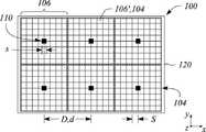
도 2a 내지 도 2c에 도시된 멀티뷰 백라이트는 상호 이격된 액티브 이미터들(110)의 어레이를 포함한다. 특히, 본 명세서의 정의에 따르면, 상기 어레이의 액티브 이미터들(110)은 유한한(즉, 0이 아닌) 이미터간 거리(예컨대, 유한한 중심간 거리)에 따라 상호 이격된다. 또한, 일부 실시예에 따르면, 상기 어레이의 액티브 이미터들(110)은 일반적으로 서로 교차하거나, 겹치거나 또는 다른 방식으로 접촉하지 않는다. 따라서, 액티브 이미터 어레이의 액티브 이미터(110) 각각은 일반적으로 어레이의 액티브 이미터들(110) 중 다른 것들과 구별되고 분리된다. 일부 실시예에서, 도 2b 및 2c에 도시된 바와 같이, 액티브 이미터들(110)은 행 및 열을 갖는 2차원(2D) 어레이(예컨대, 직사각형 어레이)로 배열될 수 있다. 다른 실시예에서(미도시), 액티브 이미터들(110)의 어레이는 선형 어레이와 같은 1차원(1D)이거나, 원형 어레이를 포함하지만 이에 제한되지 않는 다른 2D 어레이일 수 있다.The multiview backlight shown in FIGS. 2A-2C includes an array of
다양한 실시예에 따르면, 다양한 실시예에 따르면, 액티브 이미터들(110)의 어레이의 어느 액티브 이미터(110)는 복수의 지향성 광빔(102)의 형태로 광을 방출하거나 제공하도록 구성된다. 또한, 액티브 이미터(110)에 의해 제공되는 지향성 광빔들(102)은 멀티뷰 디스플레이의 상이한 뷰 방향들 각각에 대응하거나 멀티뷰 디스플레이에 의해 표시된 멀티뷰 영상과 동등하게 상이한 기본각 방향들을 가질 수 있다. 제한하는 것이 아닌 예시로서, 도 2a 및 2c는 지향성 광빔(102)을 복수의 확산 화살표로 도시한다.According to various embodiments, according to various embodiments, any
다양한 실시예에 따르면, 액티브 이미터(110)의 크기는 멀티뷰 백라이트(100)를 사용하는 멀티뷰 디스플레이의 멀티뷰 픽셀에서의 뷰 픽셀의 크기와 유사할 수 있다. 이때, ‘크기’라 함은 길이, 폭 또는 면적을 포함하지만 이에 제한되지 않는 다양한 방식으로 정의할 수 있다. 예컨대, 뷰 픽셀의 크기는 해당 길이일 수 있고, 액티브 이미터(110)의 비교 가능한 크기도 액티브 이미터(110)의 길이일 수 있다. 결국, 길이는 예컨대 인접한 뷰 픽셀들 사이의 중심간 거리와 동일할 수 있다. 다른 예에서, 크기는 면적을 의미하므로 액티브 이미터(110)의 면적을 뷰 픽셀의 면적과 비교할 수 있다.According to various embodiments, the size of the
일부 실시예에서, 액티브 이미터(110)의 크기는 뷰 픽셀의 크기와 유사하며, 액티브 이미터의 크기가 뷰 픽셀 크기의 약 50% 내지 약 200%이다. 예컨대, 액티브 이미터 크기가 ‘s’로 표시되고 뷰 픽셀 크기가 ‘S’로 표시되면(예컨대, 도 2a에 도시된 바와 같이), 액티브 이미터의 크기(s)는 다음과 같이 식 (1)로 나타날 수 있다.In some embodiments, the size of the

다른 예에서, 액티브 이미터의 크기는 뷰 픽셀 크기의 약 60%보다 크거나, 뷰 픽셀 크기의 약 70%보다 크거나, 뷰 픽셀 크기의 약 80%보다 크거나, 뷰 픽셀 크기의 약 90%보다 크고, 액티브 이미터는 뷰 픽셀 크기의 약 180%보다 작거나, 뷰 픽셀 크기의 약 160%보다 작거나, 뷰 픽셀 크기의 약 140%보다 작거나, 뷰 픽셀 크기의 약 120%보다 작다. 예컨대, ‘유사한 크기’에 의하면, 액티브 이미터의 크기는 뷰 픽셀 크기의 약 75% 내지 약 150% 사이일 수 있다. 다른 예에서, 액티브 이미터(110)는 뷰 픽셀과 크기와 유사하며, 액티브 이미터의 크기는 뷰 픽셀의 약 125% 내지 약 85% 사이이다. 일부 실시예에 따르면, 일부 실시예들에 따르면, 액티브 이미터(110)와 뷰 픽셀(106’)의 상기 유사한 크기는 멀티뷰 디스플레이의 뷰들 사이의 어두운 구역을 감소시키거나 일부 예에서는 최소화하기 위해 선택될 수 있다. 또한, 동시에, 멀티뷰 디스플레이의 뷰들간의 중첩을 감소시키거나 일부 실시예에서 최소화시킬 수 있다.In another example, the size of the active emitter is greater than about 60% of the view pixel size, greater than about 70% of the view pixel size, greater than about 80% of the view pixel size, or about 90% of the view pixel size. The larger, active emitter is less than about 180% of the view pixel size, less than about 160% of the view pixel size, less than about 140% of the view pixel size, or less than about 120% of the view pixel size. For example, according to 'similar size', the size of the active emitter may be between about 75% and about 150% of the view pixel size. In another example,
일부 실시예에서, 액티브 이미터(110)의 어레이 내에서 인접한 액티브 이미터들(110) 사이의 거리는 멀티뷰 백라이트(100)를 사용하는 멀티뷰 디스플레이의 멀티뷰 픽셀들 사이의 거리와 유사하거나 이에 상응한다. 특히, 액티브 이미터 어레이의 인접한 액티브 이미터들(110) 사이의 거리(중심간 거리 등)는 인접한 멀티뷰 픽셀 사이의 중심간 거리와 대략 동일할 수 있다. 예컨대, 상기 중심간 거리는 액티브 이미터들(110)의 각 어레이의 행 및 열 중 하나 또는 모두를 따라 정의될 수 있으며, 멀티뷰 픽셀들은 해당 어레이에 배열될 수 있다. 결과적으로, 일부 실시예들에 따르면, 멀티뷰 픽셀과 개별 액티브 이미터(110) 사이에 일대일 또는 특유의 대응 관계가 있을 수 있다.In some embodiments, the distance between adjacent
제한이 아닌 예로서, 도 2a 내지 도 2c는 본 명세서에서의 논의를 용이하게 하도록 멀티뷰 픽셀(106) 및 뷰 픽셀(106’)뿐만 아니라 광 밸브들(104)의 어레이를 더 도시한다. 도시된 광 밸브 어레이는 예컨대 멀티뷰 백라이트(100)를 사용하는 멀티뷰 디스플레이의 일부일 수 있다. 도시된 바와 같이, 광 밸브 어레이의 광 밸브들(104)은 지향성 광빔(102)을 변조하도록 구성된다. 또한, 도시된 바와 같이, 상이한 주요각 방향들을 갖는 상이한 지향성 광빔들(102)이 각각 투과되고, 광 밸브 어레이 내의 상이한 광 밸브들(104)에 의해 변조될 수 있다.As a non-limiting example, FIGS. 2A-2C further illustrate an array of
일부 실시예에서, 상기 어레이의 광 밸브(104)는 뷰 픽셀(106’)에 대응하는 반면, 광 밸브들(104)의 세트는 멀티뷰 픽셀(106)에 대응할 수 있다. 특히, 광 밸브 어레이의 광 밸브(104)의 상이한 세트는 액티브 이미터들(110) 중 상이한 것으로부터 지향성 광빔(102)들을 수신 및 변조하도록 구성된다. 따라서, 도시된 바와 같이, 액티브 이미터(110) 각각에 대해 하나의 고유한 광 밸브(104) 세트가 존재할 수 있다. 다양한 실시예에서, 액정 광 밸브들, 전기 영동 광 밸브들, 및 전기 습윤 기반 광 밸브들 중 하나 이상을 포함하지만 이에 한정되지 않는 광 밸브 어레이의 광 밸브들(104)로 상이한 유형의 광 밸브가 사용될 수 있다.In some embodiments, the
또한, 도 2a에 도시된 바와 같이, 뷰 픽셀(106’)의 크기(S)는 광 밸브 어레이에서의 광 밸브(104)의 개구 크기에 대응한다. 다른 예에서, 뷰 픽셀의 크기는 광 밸브 어레이의 인접한 광 밸브들(104) 사이의 거리(중심간 거리 등)로 정의할 수 있다. 예컨대, 광 밸브들(104)의 개구는 광 밸브 어레이에서의 광 밸브들(104) 사이의 중심간 거리보다 작을 수 있다. 따라서, 다른 정의에 따르면, 뷰 픽셀의 크기는 광 밸브(104)의 크기 또는 광 밸브들(104) 사이의 중심간 거리에 대응하는 크기로 정의할 수 있다. 또한, 도 2a는 액티브 이미터(110)의 크기(s)가 뷰 픽셀 크기(S)와 유사한 것으로 도시되어 있다.Also, as shown in FIG. 2A, the size S of the
일부 실시예에서(예컨대, 도 2a에 도시된 바와 같이), 한 쌍의 인접한 액티브 이미터들(110) 사이의 요소간 거리(중심 간 거리 등)는 예컨대 광 밸브 세트로 표시되는 대응하는 인접한 한 쌍의 멀티뷰 픽셀들(106) 사이의 픽셀간 거리(중심간 거리 등)와 동일할 수 있다. 예컨대, 도 2a에 도시된 바와 같이, 제1 액티브 이미터(110a)와 제2 액티브 이미터(110b) 사이의 중심간 거리(d)는 제1 광 밸브 세트(104a)와 제2 광 밸브 세트(104b) 사이의 거리(D)와 실질적으로 동일하며, 광 밸브 세트(104a, 104b) 각각은 상이한 멀티뷰 픽셀(106)을 나타낸다. 다른 실시예(미도시)에서, 한 쌍의 액티브 이미터(110a, 110b)(또는 액티브 이미터(110))의 상대적 중심간 거리 및 해당 광 밸브 세트(104a, 104b)는 상이할 수 있다. 예컨대, 액티브 이미터들(110)은 멀티뷰 픽셀(106)을 나타내는 광 밸브 세트들 사이의 간격(즉, 중심간 거리(D))보다 크거나 작은 요소간 간격(즉, 중심간 거리(d))를 가질 수 있다.In some embodiments (eg, as shown in FIG. 2A), the inter-element distance (such as center-to-center distance) between a pair of adjacent
일부 실시예에서, 액티브 이미터(110)의 형상은 멀티뷰 픽셀(106)의 형상과 유사하거나 멀티뷰 픽셀(106)에 대응하는 광 밸브들(104)의 세트(또는 ‘서브-어레이’)의 형상과 등가적이다. 예컨대, 액티브 이미터(110)는 정사각형 형상일 수 있고, 멀티뷰 픽셀(106)(또는 대응하는 광 밸브들(104) 세트의 배열)은 실질적으로 정사각형일 수 있다. 다른 예에서, 액티브 이미터(110)는 직사각형 형상일 수 있다. 즉, 폭 또는 횡방향 치수보다 큰 길이 또는 종방향 치수를 가질 수 있다. 본 예에서, 액티브 이미터(110)에 대응하는 멀티뷰 픽셀(106)(또는 이와 동등한 광 밸브(104) 세트의 배열)은 유사한 직사각형 형상일 수 있다. 도 2b 및 2c는 정사각형의 액티브 이미터들(110) 및 정사각형의 광 밸브(104) 세트들을 포함하는 해당 정사각형 멀티뷰 픽셀들(106)을 도시한다. 또 다른 예(미도시)에서, 액티브 이미터들(110) 및 해당 멀티뷰 픽셀들(106)은 삼각형, 육각형 및 원형을 포함하거나 적어도 대략적으로 유사하지만 이에 제한되지 않는 다양한 형상을 갖는다. 보다 일반적으로, 상기 형상은 실질적으로 임의의 타일 형상을 나타낼 수 있다.In some embodiments, the shape of the
일부 실시예에 따르면, 액티브 이미터 어레이의 액티브 이미터(110)는 마이크로 발광 다이오드(microLED 또는 μLED)를 포함할 수 있다. 본 명세서에서, μLED는 미세 발광 다이오드(LED), 즉 미세한 치수를 갖는 LED로 정의한다. 일부 실시예에서, μLED는 조합하면 뷰 픽셀 크기와 유사한 크기를 갖는 복수의 μLED를 포함할 수 있다. 일부 실시예에 따르면, 액티브 이미터 어레이의 액티브 이미터(110)는 유기 발광 다이오드(OLED)를 포함할 수 있다. 본 명세서에 정의된 바와 같이, OLED는 전류 또는 유사한 전기 자극에 응답하여 광을 방출하도록 구성된 유기 화합물을 포함하는 방출성 전자 발광 필름 또는 층을 구비한 이미터이다. 다른 실시예에서, 다른 유형의 액티브 광학 이미터가, 뷰 픽셀 크기에 유사한 크기를 갖는 고강도 LED 및 양자점 LED와 같은 액티브 이미터(110) 등으로 사용될 수 있지만 이에 한정되지 않는다.According to some embodiments, the
일부 실시예에서, 액티브 이미터(110)는 특정 색상을 갖는 실질적으로 단색인 광을 제공하도록 구성될 수 있다(즉, 광은 특정 파장의 광을 포함할 수 있다). 다른 실시예에서, 액티브 이미터(110)는 복수의 또는 소정 범위의 파장을 포함하는 백색광과 같은 다색광을 제공하도록 구성될 수 있지만 이에 제한되지는 않는다. 예컨대, 액티브 이미터(110)는 적색광, 녹색광, 청색광 또는 이들의 조합 중 하나 이상을 제공하도록 구성될 수 있다. 다른 예에서, 액티브 이미터(110)는 실질적으로 백색 광을 제공하도록 구성될 수 있다(즉, 액티브 이미터(110)는 백색 μLED 또는 백색 OLED일 수 있다). 일부 실시예에서, 액티브 이미터(110)는 마이크로 렌즈나 회절 격자를 포함하거나 방출된 광의 시준(예컨대, 시준 계수에 따름) 및 편광 제어의 하나 또는 둘 다, 또는 지향성 광빔(102)의 등가를 제공하도록 구성된 기타 광학 필름이나 성분을 포함할 수 있다. 상기 마이크로 렌즈, 회절 격자 또는 기타 광학 필름이나 성분은 지향성 광빔(102)의 방향을 제어하도록 구성될 수도 있다. 또는, 예컨대, 상기 시준 및 편광 제어 중 하나 또는 모두는 액티브 이미터 어레이들과 광 밸브 어레이 사이의 광학 층 또는 필름에 의해 제공될 수 있다.In some embodiments,
일부 실시예에 의하면, 액티브 이미터 어레이의 액티브 이미터(110)는 국소 조광(local dimming)을 제공하도록, 그리고 제1 및 제2 액티브 이미터 어레이에 의한 지향성 광빔 생성간 전환이 가능하도록 독립적으로 제어, 활성화 또는 전력 공급될 수 있다. 특히, 일부 실시예에서, 액티브 이미터 어레이의 액티브 이미터(들)(110)는, 예컨대 제1 시간 간격 또는 특정 모드 중에 복수의 지향성 광빔(102)을 선택적으로 활성화하여 제공하도록 구성될 수 있다.According to some embodiments, the
일부 실시예에서, 멀티뷰 백라이트(100)는 색상 멀티뷰 영상들을 제공하거나 표시하도록 구성된 색상 멀티뷰 디스플레이와 연동될 수 있다. 색상 멀티뷰 디스플레이에서, 상이한 광 밸브들(104), 보다 구체적으로 광 밸브들(104)의 상이한 부분들은 상이한 색상들을 (예컨대, 색상 필터를 사용하여) 제공할 수 있고, 따라서, 광 밸브들(104)의 ‘컬러 서브-픽셀’로 칭할 수 있다. 특히, 상이한 색상을 나타내는 컬러 서브-픽셀들의 세트는 광을 상이한 색상의 광으로 변조하기 위해 서로 인접하게 제공될 수 있다. 예컨대, 광의 상이한 색상 및 컬러 서브-픽셀의 해당되는 상이한 색상은 적-녹-청(RGb) 색상 모델의 적색, 녹색 및 청색일 수 있다. 일부 실시예에서, 상이한 색상을 나타내는 컬러 서브-픽셀들은 광 밸브의 행을 따라 번갈아 나타날 수 있다(예컨대, 적색, 녹색, 청색, 적색, 녹색, 청색 등). 이들 실시예에서, 멀티뷰 픽셀(106)의 광 밸브(104) 또는 이와 등가의 뷰 픽셀(106’)은 뷰 픽셀들(106’)의 행을 따라 유사하게 교번되는 컬러 서브-픽셀의 세트로 나타날 수 있다. 이와 같이, 멀티뷰 픽셀(106)의 뷰 픽셀(106’)은 3개의 컬러 서브-픽셀들(예컨대, 적색, 녹색 및 청색)의 세트로 나타날 수 있다. 다른 실시예(미도시)에서, 뷰 픽셀(106’)은 3개 초과 또는 미만의 컬러 서브-픽셀의 세트를 포함할 수 있다. 이들 실시예 중 일부에서, 액티브 이미터(110)는 뷰 픽셀(106 ‘)(또는 광 밸브(104))의 컬러 서브-픽셀 세트의 컬러 서브-픽셀들에 대응하는 색상을 갖는 복수의 컬러 이미터를 포함할 수 있다.In some embodiments, the
일부 실시예에서, 액티브 이미터 어레이의 상이한 컬러 이미터들은 액티브 이미터 어레이 또는 광 밸브 어레이의 행 방향 및 열 방향 중 하나 또는 모두에서 서로 오프셋된다. 특히, 일부 실시예에 의하면, 행 방향으로의 오프셋은 멀티뷰 백라이트(100)와 연동된 색상 멀티뷰 디스플레이에서 색록을 실질적으로 감소시키거나 억제하도록 구성될 수 있다.In some embodiments, different color emitters of the active emitter array are offset from each other in one or both of the row and column directions of the active emitter array or the light valve array. In particular, in some embodiments, the offset in the row direction may be configured to substantially reduce or suppress color rock in a color multiview display in conjunction with the
도 3a는 본 명세서에 설명된 원리에 일치하는 실시예에 따른 일 예로서의 멀티뷰 백라이트를 나타내는 평면도이다. 도 3b는 본 명세서에 설명된 원리에 일치하는 실시예에 따른 일 예로서의 멀티뷰 픽셀의 일부 및 도 3a의 멀티뷰 백라이트의 일부를 나타내는 평면도이다. 특히, 도 3a는 복수의 컬러 이미터(112)를 포함하는 각각의 액티브 이미터(110)를 구비하는 멀티뷰 백라이트(100)의 액티브 이미터(110)를 도시한다. 도 3b에서, 상기 멀티뷰 픽셀(106)의 도시된 부분은 액티브 이미터(110) 상에 복수의 컬러 이미터(112)와 중첩된 복수의 뷰 픽셀(106’) 또는 이와 등가의 복수의 광 밸브(104)를 포함한다. 예컨대, 도 3a 및 도 3b에 도시된 실시예의 멀티뷰 백라이트(100)는 색상 멀티뷰 영상들을 제공하거나 표시하도록 구성된 색상 멀티뷰 디스플레이와 연동될 수 있다.3A is a plan view illustrating an example multiview backlight in accordance with an embodiment consistent with the principles described herein. 3B is a plan view illustrating a portion of a multiview pixel as an example and a portion of the multiview backlight of FIG. 3A according to an embodiment consistent with the principles described herein. In particular, FIG. 3A shows the
도 3a 및 도 3b에서, 액티브 이미터(110)는 3가지 상이한 색의 광(적색광, 녹색광 및 청색광 등) 각각에 대응하는 3개의 컬러 이미터(112a, 112b, 112c)를 예시로서 포함하지만 이에 제한되지 않는다. 또한, 도 3b에 도시된 바와 같이, 컬러 이미터(112a, 112b, 112c)의 3개의 상이한 색상들은 멀티뷰 픽셀(106)의 뷰 픽셀(106’)의 3개의 상이한 컬러 서브-픽셀의 색상들에 대응한다. 특히, 도 3b는 3개의 상이한 컬러 이미터(112a, 112b, 112c)의 뷰 픽셀(106’)을 도시하고 있는데, 각각의 뷰 픽셀(106’)은 3개의 상이한 색상인 적색(R), 녹색(G) 및 청색(b)을 나타내는 3개의 컬러 서브-픽셀을 포함한다. 도 3b에서, 컬러 이미터(112a, 112b, 112c)와 뷰 픽셀(106’)을 구별하기 위해 음영을 사용하였다.In Figures 3A and 3B, the
전술한 멀티뷰 백라이트(100)와 같이, 멀티뷰 백라이트(100)의 액티브 이미터(110)의 크기는 멀티뷰 백라이트(100)에 연동된 멀티뷰 디스플레이의 뷰 픽셀(106’)의 크기와 유사할 수 있다. 또한, 액티브 이미터(110)가 복수의 컬러 이미터(112)를 포함하는 경우, 각각의 컬러 이미터(112)는 뷰 픽셀 크기와 유사한 크기를 가질 수 있다. 도 3a는 전술한 액티브 이미터 크기(s)와 동등한 크기(s)를 갖는 컬러 이미터(112. 예컨대, 112a, 112b 및 112c)를 도시한다. 도 3b는 컬러 이미터(112)의 크기(s)와 유사한 뷰 픽셀(106’)의 크기(S)를 도시한다. 또한, 액티브 이미터 어레이에서 인접한 액티브 이미터들(110)(또는 등가적으로, 동일한 색상의 컬러 이미터들(112)) 사이의 거리는 멀티뷰 디스플레이의 인접한 멀티뷰 픽셀들(도 3a에 미도시) 사이의 거리(D)에 상응한다. 또한, 도 3b는 뷰 픽셀(106 ‘)의 행 방향을 따라 교번하는 뷰 픽셀(106’)의 컬러 서브-픽셀을 도시한다(예컨대, R, G, B, R, G, …). 마찬가지로, 도 3a 및 도 3b는 서로 상이한 색상의 컬러 이미터(112)(즉, 112a = R, 112b = G, 112c = B) 또한 행 방향을 따라 교번하는 것을 도시한다.Like the
본 명세서에서, 인접한 컬러 이미터(112) 사이의 오프셋 또는 이와 동등한 오프셋 거리는 인접한 색상 이미 터(112) 상에서 일치하는 위치들 사이의 거리로 정의한다. 예컨대, 상기 오프셋은 인접한 컬러 이미터(112) 사이의 중심간 거리를 나타낼 수 있다. 다른 예에서, 상기 오프셋은 인접한 컬러 이미터(112)들의 동일 측면 사이의 거리를 나타낼 수 있다. 일부 실시예에서, 행 방향으로 인접한 컬러 이미터(112) 사이의 오프셋의 거리는 뷰 픽셀 크기의 정수배에 뷰 픽셀 크기를 뷰 픽셀 내의 컬러 서브-픽셀의 개수로 나눈 값을 더한 것에 비례하며, 컬러 서브-픽셀은 행 방향으로 뷰 픽셀(106’) 내에 배열된다. 특히, 뷰 픽셀 크기(S)가 주어지고 ‘p’가 뷰 픽셀(106’)에서의 컬러 서브-픽셀의 개수를 나타내는 경우, 행을 따라 또는 액티브 이미터 어레이의 행 방향으로 인접한 컬러 이미터(112) 사이의 오프셋(r) 또는 오프셋 거리는 다음과 같은 식 (2)로 나타난다.In the present specification, the offset between the

이때, ‘n’은 정수이다. 예컨대, 도 3a에 도시된 바와 같이, 컬러 이미터(112a)는 액티브 이미터 어레이의 행 방향을 따라 인접 컬러 이미터(112b)로부터 오프셋된다. 뷰 픽셀(106’)은 3개의 컬러 서브-픽셀(즉, p = 3)을 포함하기 때문에, 멀티뷰 백라이트(100)의 인접한 컬러 이미터(112) 사이의 오프셋의 거리(r)는 뷰 픽셀 크기(S)의 1/3에 S를 더한 값이다(즉, n = 1이라고 가정할 때 r = S + S/3). 다시 말해, 도 3b에 도시된 바와 같이, 인접한 컬러 이미터(112a 및 112b)는 4개의 컬러 서브-픽셀에 대응하는 거리만큼 행 방향으로 오프셋된다. 이와 유사하게, 도시된 바와 같이, 인접한 컬러 이미터(112b, 112c)는 행 방향으로 4개의 컬러 서브-픽셀만큼 오프셋된다. 즉, 각각의 컬러 이미터(112)는 뷰 픽셀 크기(S)의 크기와 동일한 크기(s)를 갖기 때문에, 식 (2)의 결과, 컬러 서브-픽셀의 개수에 1을 더한 값만큼 인접한 컬러 이미터(112)의 오프셋을 제공한다. 다른 실시예(미도시)에서, 정수 n이 0이면(즉, n = 0), 인접한 컬러 이미터(112) 사이의 오프셋(r)은 뷰 픽셀 크기 S의 1/3(즉, r = S/3)이다. 이 경우, 행 방향으로 오프셋된 컬러 이미터들(112)은 중복될 수 있다.In this case, 'n' is an integer. For example, as shown in FIG. 3A,
일부 실시예에서, 액티브 이미터 어레이의 컬러 이미터들(112)은 행 방향에 직교하는 액티브 이미터 어레이의 열 방향으로 서로 오프셋된다. 특히, 열 방향으로의 오프셋의 거리는 뷰 픽셀들(106’)의 열 사이의 중심간 거리 또는 등가적으로 광 밸브 어레이의 광 밸브(104)의 정수배에 상응할 수 있다. 도 3a 및 3b는 액티브 이미터 어레이의 열 방향을 따라 인접 컬러 이미터 사이의 오프셋을 도시한다. ‘l’이 뷰 픽셀들(106’)의 행 사이의 중심간 거리를 의미하는 경우, 컬러 이미터들(예컨대, 컬러 이미터(112a) 및 컬러 이미터(112b))의 열 방향을 따른 오프셋 ‘c’는 다음 식 (3)으로 나타날 수 있다.In some embodiments, the

이때, ‘m’은 정수이다. 예컨대, 도 3b에 도시된 바와 같이, m = 1인 경우, 열 방향의 컬러 이미터(112a)와 컬러 이미터(112b) 사이의 오프셋(c)은 l과 동일하거나 뷰 픽셀들(106’)의 행 사이의 중심간 거리와 동일하다. m = 0인 다른 실시예 (미도시)에서, 열 방향으로 컬러 이미터들 사이의 오프셋은 0이거나 존재하지 않는다. 이러한 실시예에서, 컬러 이미터(112a) 및 컬러 이미터(112b) (및 이와 관련된 모든 컬러 이미터(112))는 액티브 이미터(110)의 어레이의 열을 따라 정렬될 수 있다. 식 (2)에서 정수 n이 1 이상인 경우(즉, n ≥ 1), 행 방향으로 중복이 존재하지 않음에 유의한다.In this case, 'm' is an integer. For example, as shown in FIG. 3B, when m = 1, the offset c between the
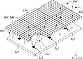
도 2a를 다시 참조하면, 일부 실시예에서, 멀티뷰 백라이트(100)는 평면 기판(120)을 더 포함할 수 있다. 특히, 액티브 이미터(110)들은 평면 기판(120)의 표면에 걸쳐 상호 이격될 수 있다. 상기 평면 기판(120)은 액티브 이미터들(110)에 전원을 제공하기 위해 전기적 상호연결부들을 더 포함할 수 있다. 일부 실시예에서, 상기 평면 기판(120)은 광학적으로 투명하거나 적어도 실질적으로 광학적으로 투명하도록 구성된다(즉, 평면 투명 기판일 수 있다). 예컨대, 평면 기판(120)은 평면 기판(120)의 제1 면으로부터 제2 면으로 광을 투과시킬 수 있는 광학적 투명 재질을 포함할 수 있다. 또한, 일부 실시예에서, 전기적 상호연결부는 광학적으로 투명할 수 있다. 또한, 일부 실시예에서, 액티브 이미터들(110)의 어레이와 평면 기판(120)의 조합(예컨대, 전기적 상호연결부와 함께)은 광학적으로 투명하도록 구성될 수 있다.Referring back to FIG. 2A, in some embodiments, the
일부 실시예에 따르면, 멀티뷰 백라이트(100)는 평면 기판(120)에 인접한 광각 백라이트를 더 포함할 수 있다. 상기 광각 백라이트는 광각 방출광을 제공하도록 구성될 수 있다. 또한, 다양한 실시예에 따라, 액티브 이미터들(110)의 어레이와 평면 기판(120)의 조합은 광각 방출광에 대해 투명하도록 구성될 수 있다. 따라서, 광각 광은 광각 백라이트로부터 방출되어 멀티뷰 백라이트(100)의 평면 기판의 두께를 투과할 수 있다.According to some embodiments, the
도 4는 본 명세서에 설명된 원리에 일치하는 실시예에 따른 일 예로서의 광각 백라이트를 포함하는 멀티뷰 백라이트의 단면도를 도시한다. 특히, 도 4는 대향하는 표면 상에 배열된 액티브 이미터들(110)을 구비하는 평면 기판(120)의 표면에 인접한 광각 백라이트(130)를 도시한다. 또한, 도 4는 평면 기판(120)의 대향하는 표면에 인접한 광 밸브(104)의 어레이를 도시한다.4 illustrates a cross-sectional view of a multiview backlight including an example wide-angle backlight according to an embodiment consistent with the principles described herein. In particular, FIG. 4 shows a wide-
도 4의 좌측에 도시된 바와 같이, 액티브 이미터(110)를 활성화함으로써 멀티뷰 백라이트(100)를 사용하여 지향성 광빔(102)을 제공함으로써, 멀티뷰 영상(MULTIVIEW)이 제공될 수 있다. 또는, 도 4의 우측에 도시된 바와 같이, 액티브 이미터들(110)을 비활성화하고 광각 백라이트(130)를 활성화하여 광각 방출광(132)을 광 밸브(104) 어레이에 제공함으로써 2차원(2D) 영상이 제공될 수 있다. 따라서, 다양한 실시예들에 따르면, 광각 백라이트(130) 및 투명하게 구성된 평면 기판(120)을 포함하는 멀티뷰 백라이트(100)는 멀티뷰 영상을 표시하는 것과 2D 영상을 표시하는 것 사이에서 전환될 수 있는 전자 디스플레이를 구현하는데 사용될 수 있다. 본 명세서에서, 액티브 이미터들(110)은 음영을 사용하여 활성화된 것으로 도시하였고, 음영이 없는 액티브 이미터들(110)은 비활성화된 상태 또는 조건을 나타내는 것으로 도시하였다.As shown on the left side of FIG. 4, a multiview image MULTIVIEW may be provided by providing the directional
본 명세서에 설명된 원리에 의한 일부 실시예에 따르면, 멀티뷰 디스플레이가 제공된다. 다양한 실시예들에 따르면, 멀티뷰 디스플레이는 멀티뷰 영상을 표시하도록 구성된다. 도 5는 본 명세서에 설명된 원리에 일치하는 실시예에 따른 일 예로서의 멀티뷰 디스플레이의 블록도를 나타낸다. 도시된 바와 같이, 멀티뷰 디스플레이(200)는 액티브 이미터들(210)의 어레이를 포함한다. 일부 실시예들에 따르면, 액티브 이미터 어레이의 액티브 이미터들(210)은 평면 기판 상에서 서로 이격될 수 있다. 액티브 이미터 어레이의 액티브 이미터들(210)은 멀티뷰 영상의 상이한 뷰 방향들에 대응하는 상이한 주요각 방향들을 갖는 지향성 광빔들(202)을 제공하도록 구성된다. 멀티뷰 디스플레이(200)는 지향성 광빔(202)을 변조하고 멀티뷰 영상을 제공하도록 구성된 광 밸브(220)의 어레이를 더 포함한다. 광 밸브 어레이의 광 밸브(220)는 복수의 멀티뷰 픽셀로 배열된다(즉, 상이한 광 밸브(220) 세트가 상이한 멀티뷰 픽셀들에 대응한다). 다양한 실시예에 따르면, 액티브 이미터 어레이의 액티브 이미터(210)의 크기는 광 밸브 어레이의 광 밸브 (220)의 크기의 1/2 배 내지 2배이다. 또한, 다양한 실시예들에 따르면, 인접한 액티브 이미터(210) 사이의 거리는 인접한 멀티뷰 픽셀 사이의 거리에 상응한다.According to some embodiments according to the principles described herein, a multiview display is provided. According to various embodiments, the multiview display is configured to display a multiview image. 5 shows a block diagram of an example multiview display in accordance with an embodiment consistent with the principles described herein. As shown, the
일부 실시예에서, 액티브 이미터들(210)의 어레이는, 전술한 멀티뷰 백라이트(100)에 대한 액티브 이미터들(110)의 어레이와 실질적으로 유사할 수 있다. 특히, 액티브 이미터 어레이의 액티브 이미터들(210)은 마이크로 발광 다이오드(μLED) 및 유기 발광 다이오드 (OLED) 중 하나 또는 모두를 포함할 수 있다. 일부 실시예에서, 광 밸브(220)의 어레이는 전술한 멀티뷰 백라이트(100)의 광 밸브(104) 어레이와 실질적으로 유사할 수 있다. 특히, 광 밸브 어레이의 광 밸브(220) 각각은 광 밸브 어레이의 행 방향으로 광 밸브 내에 배열된 복수의 컬러 서브-픽셀을 포함할 수 있다. 또한, 액티브 이미터 어레이의 액티브 이미터들(210)은 컬러 서브-픽셀들의 색상에 대응하는 색상을 갖는 광을 방출하도록 구성된 복수의 컬러 이미터를 포함할 수 있다. 예컨대, 상기 색상들은 적색, 녹색 및 청색을 포함할 수 있다. 일부 실시예에서, 컬러 이미터는 액티브 이미터(110)의 컬러 이미터(112)와 실질적으로 유사할 수 있다. 일부 실시예에서, 평면 기판은 전술한 멀티뷰 백라이트(100)에 대한 평면 기판(120)과 실질적으로 유사할 수 있다.In some embodiments, the array of
일부 실시예에서, 각각의 액티브 이미터(210)의 컬러 이미터들은 광 밸브 크기의 정수배에 광 밸브 크기를 컬러 서브-픽셀의 개수로 나눈 값을 더한 비율의 거리만큼 광 밸브 어레이의 행 방향으로 서로 오프셋 될 수 있다. 일부 실시예에서, 액티브 이미터(210) 각각의 컬러 이미터들은 행 방향에 직교하는 광 밸브 어레이의 열 방향으로 열 방향의 광 밸브 어레이의 행들 사이의 중심간 거리의 정수배에 대응하는 거리만큼 서로 오프셋될 수 있다.In some embodiments, the color emitters of each
일부 실시예(미도시)에서, 멀티뷰 디스플레이(200)는 평면 기판에 인접한 광각 백라이트를 더 포함한다. 상기 광각 백라이트는 광각 방출광을 제공하도록 구성될 수 있다. 다양한 실시예에 따르면, 액티브 이미터들(210)의 어레이와 평면 기판의 조합은 광각 방출광에 대해 투명하도록 구성된다. 일부 실시예에서, 광각 백라이트는 전술한 멀티뷰 백라이트(100)의 광각 백라이트(130)와 실질적으로 유사할 수 있다. 광각 백라이트를 포함하는 일부 실시예에서, 멀티뷰 디스플레이(200)는 액티브 이미터들(210)에 의해 제공되고 광 밸브 어레이에 의해 변조된 지향성 광빔(202)을 사용하여 제1 모드 동안 멀티뷰 영상을 표시하도록 구성된다. 또한, 멀티뷰 디스플레이(200)는 광각 백라이트에 의해 제공되고 광 밸브 어레이에 의해 변조된 광각 방출광을 사용하여 제2 모드 동안 2차원(2D) 영상을 표시하도록 구성될 수 있다.In some embodiments (not shown), the
본 명세서에 설명된 원리에 의한 일부 실시예에 따르면, 멀티뷰 디스플레이의 작동 방법이 제공된다. 도 6은 본 명세서에 설명된 원리에 일치하는 실시예에 따른 일 예로서의 멀티뷰 디스플레이 작동 방법의 흐름도를 도시한다. 본 방법은 평면 기판 상에 이격된 액티브 이미터의 어레이를 사용하여 복수의 지향성 광빔을 방출하는 단계(310)를 포함한다. 일부 실시예에서, 액티브 이미터 어레이의 액티브 이미터는 전술한 멀티뷰 백라이트(100)의 액티브 이미터(110)와 실질적으로 유사하다. 특히, 액티브 이미터 어레이의 액티브 이미터는 멀티뷰 영상의 상이한 뷰 방향들에 대응하는 주요각 방향들을 갖는 지향성 광빔을 제공하도록 구성된다. 일부 실시예에서, 액티브 이미터 어레이의 액티브 이미터들은 백색광을 제공하도록 구성된다. 일부 실시예에서, 액티브 이미터 어레이의 액티브 이미터들은 색상을 갖는 광을 제공하도록 구성된다.According to some embodiments according to the principles described herein, a method of operating a multiview display is provided. 6 shows a flowchart of a method of operating a multiview display according to an embodiment consistent with the principles described herein. The method includes emitting 310 a plurality of directional light beams using an array of active emitters spaced apart on a planar substrate. In some embodiments, the active emitter of the active emitter array is substantially similar to the
상기 방법(300)은 멀티뷰 영상을 표시하기 위해 복수의 멀티뷰 픽셀들로 배열된 광 밸브들의 어레이를 사용하여 복수의 지향성 광빔들을 변조하는 단계(320)를 더 포함한다. 광 밸브들의 어레이는 전술한 멀티뷰 백라이트(100)에 대한 광 밸브들(104)의 어레이와 실질적으로 유사할 수 있다. 특히, 평면 기판 상의 액티브 이미터들의 어레이로부터의 지향성 광빔들은 멀티뷰 영상의 뷰를 나타내는 변조된 지향성 광빔을 제공하기 위해 광 밸브 어레이의 개별 광 밸브에 의해 투과되고 변조될 수 있다(320). 다양한 실시예에 따르면, 상이한 주요각 방향을 갖는 지향성 광빔들은 각각 광 밸브 어레이 내의 광 밸브 중 상이한 광 밸브를 통과하여 변조되도록 구성된다(320).The
또한, 다양한 실시예에 따르면, 액티브 이미터 어레이의 액티브 이미터의 크기는 광 밸브 어레이의 광 밸브의 크기와 유사하다. 구체적으로, 액티브 이미터 어레이의 액티브 이미터의 크기는 광 밸브 어레이의 광 밸브 크기의 1/2 배 내지 2배일 수 있다. 또한, 다양한 실시예에 따르면, 액티브 이미터 어레이 내의 인접한 액티브 이미터 사이의 거리는 인접한 멀티뷰 픽셀 사이의 거리에 상응한다. 특히, 어레이의 인접한 액티브 이미터 쌍 사이의 요소간 거리(중심간 거리 등)는 예컨대, 광 밸브 세트로 나타나는 인접한 해당 멀티뷰 픽셀 쌍 사이의 픽셀간 거리(중심간 거리등)와 동일할 수 있다.Further, according to various embodiments, the size of the active emitter of the active emitter array is similar to the size of the light valve of the light valve array. Specifically, the size of the active emitter of the active emitter array may be 1/2 to 2 times the size of the light valve of the light valve array. Further, according to various embodiments, the distance between adjacent active emitters in the active emitter array corresponds to the distance between adjacent multiview pixels. In particular, the inter-element distance (center-to-center distance, etc.) between adjacent pairs of active emitters in the array may be equal to, for example, the inter-pixel distance (center-to-center distance, etc.) between adjacent corresponding multiview pixel pairs represented by a set of light valves. .
일부 실시예에서, 광 밸브 어레이의 광 밸브 각각은 광 밸브 어레이의 행 방향으로 광 밸브 내에 배열된 복수의 컬러 서브-픽셀을 포함한다. 특히, 적색-녹색-청색(RGB)을 나타내는 컬러 서브-픽셀의 세트는 광 밸브 어레이에서 서로 인접하여 제공될 수 있다. 예컨대, 상이한 색상을 나타내는 컬러 서브-픽셀들은 픽셀의 행을 따라 교번될 수 있다(예컨대, 적색, 녹색, 청색, 적색, 녹색, 청색 등).In some embodiments, each of the light valves of the light valve array includes a plurality of color sub-pixels arranged in the light valve in the row direction of the light valve array. In particular, a set of color sub-pixels representing red-green-blue (RGB) may be provided adjacent to each other in the light valve array. For example, color sub-pixels representing different colors can be alternating along a row of pixels (eg, red, green, blue, red, green, blue, etc.).
일부 실시예에서, 복수의 지향성 광빔을 방출하는 단계는 복수의 컬러 이미터의 각각의 컬러 이미터로부터 상이한 색상의 광을 복수의 지향성 광빔으로 방출하는 단계를 포함하며, 이때, 액티브 이미터 어레이의 액티브 이미터들은 복수의 컬러 이미터 및 광 밸브 어레이의 광 밸브 내의 복수의 컬러 서브-픽셀의 상이한 컬러 서브-픽셀의 색상에 대응하는 광의 상이한 각각의 색상을 포함한다. 광 밸브 어레이 내에 서로 인접하게 제공되는 컬러 서브-픽셀의 세트가 적색, 녹색 및 청색을 나타내는 실시예에 있어서, 컬러 이미터들에 의해 방출된 색상들은 이와 대응하도록 적색, 녹색 및 청색을 포함할 수 있다.In some embodiments, emitting the plurality of directional light beams includes emitting light of a different color from each color emitter of the plurality of color emitters into the plurality of directional light beams, wherein the array of active emitters Active emitters include a plurality of color emitters and respective respective colors of light corresponding to the colors of different color sub-pixels of the plurality of color sub-pixels in the light valves of the light valve array. In an embodiment where the set of color sub-pixels provided adjacent to each other in the light valve array represent red, green and blue, the colors emitted by the color emitters may include red, green and blue correspondingly. .
일부 실시예(미도시)에서, 상기 방법(300)은 광 밸브 어레이에 인접한 평면 기판의 표면에 대향하는 평면 기판의 표면에 인접한 광각 백라이트를 사용하여 광각 방출광을 제공하는 단계를 더 포함한다. 광각 백라이트는 멀티뷰 디스플레이의 평면 기판을 향해 광각의 광을 제공하도록 구성된다. 다양한 실시예에서, 액티브 이미터 어레이와 평면 기판의 조합은 광각 방출광에 대해 투명하다. 결과적으로, 광각 백라이트로부터의 광각의 광은 평면 기판의 두께를 투과되며, 광각의 광으로 방출되는 평면 기판에 의해 발광한다.In some embodiments (not shown), the
일부 실시예(미도시)에서, 상기 방법(300)은 2차원(2D) 영상을 표시하기 위해 광 밸브의 어레이를 사용하여 광각 방출광을 변조하는 단계를 더 포함한다. 전술한 바와 같이, 멀티뷰 영상은 복수의 지향성 광빔을 방출 및 변조함으로써 제1 모드 동안 표시될 수 있다. 또한, 2차원 영상은 광각 방출광을 제공 및 변조함으로써 제2 모드 동안 표시될 수 있다.In some embodiments (not shown), the
이상으로, 멀티뷰 백라이트, 멀티뷰 디스플레이, 및 액티브 이미터들을 포함하는 백라이트 작동 방법의 예들 및 실시예들을 설명하였다. 상기 설명된 예들은 본 명세서에서 설명된 원리를 나타내는 다수의 특정 예들 중 일부만을 예시할 뿐임을 유의하여야 한다. 명백히, 당업자는 아래의 청구 범위에 의해 정의를 벗어나지 않는 범위 내에서 수많은 다른 배치들도 용이하게 적용할 수 있는 것으로 이해되어야 할 것이다.In the above, examples and embodiments of a method of operating a backlight including a multiview backlight, a multiview display, and active emitters have been described. It should be noted that the examples described above only illustrate some of the many specific examples that illustrate the principles described herein. Apparently, it will be understood by those skilled in the art that many other arrangements can be readily applied without departing from the definition of the following claims.
Claims (20)
Translated fromKorean상기 액티브 이미터의 크기는 상기 멀티뷰 디스플레이의 멀티뷰 픽셀의 뷰 픽셀의 크기에 상당하며 ,
상기 액티브 이미터 어레이 내에서 인접한 액티브 이미터들 사이의 거리는 상기 멀티뷰 디스플레이의 인접한 멀티뷰 픽셀 사이의 거리에 상응하는 것을 특징으로 하는 멀티뷰 백라이트.
An array of active emitters spaced apart from one another and emitting light in the form of a plurality of directional light beams having different principal angular directions corresponding to respective different viewing directions of the multiview display,
The size of the active emitter corresponds to the size of the view pixel of the multiview pixel of the multiview display,
And the distance between adjacent active emitters in the active emitter array corresponds to the distance between adjacent multiview pixels of the multiview display.
상기 액티브 이미터는 마이크로 발광 다이오드(μLED)를 포함하는 것을 특징으로 하는 멀티뷰 백라이트.
The method of claim 1,
The active emitter includes a micro light emitting diode (μLED).
상기 액티브 이미터는 유기 발광 다이오드(OLED)를 포함하는 것을 특징으로 하는 멀티뷰 백라이트.
The method of claim 1,
The active emitter includes an organic light emitting diode (OLED).
상기 액티브 이미터는 백색광을 발광하는 것을 특징으로 하는 멀티뷰 백라이트.
The method of claim 1,
And the active emitter emits white light.
상기 액티브 이미터 어레이의 상기 액티브 이미터는 각각 복수의 컬러 이미터를 포함하며,
상기 복수의 컬러 이미터 각각은 상기 뷰 픽셀 크기에 대응하는 크기를 가지고, 상기 뷰 픽셀 내의 복수의 컬러 서브-픽셀 중 해당 컬러 서브-픽셀의 색상을 갖는 빛을 방출하는 것을 특징으로 하는 멀티뷰 백라이트.
The method of claim 1,
The active emitters of the active emitter array each include a plurality of color emitters,
Wherein each of the plurality of color emitters has a size corresponding to the view pixel size and emits light having a color of the corresponding color sub-pixel of the plurality of color sub-pixels within the view pixel. .
상기 액티브 이미터의 상기 컬러 이미터들은 상기 뷰 픽셀 크기의 정수배에 상기 뷰 픽셀 크기를 상기 뷰 픽셀 내의 상기 컬러 서브-픽셀의 개수로 나눈 값을 더한 것에 비례하는 거리만큼 상기 액티브 이미터 어레이의 행 방향으로 서로 오프셋되며,
상기 컬러 서브-픽셀은 상기 행 방향으로 상기 뷰 픽셀 내에 배열되는 것을 특징으로 하는 멀티뷰 백라이트.
The method of claim 5,
The color emitters of the active emitter are rows of the active emitter array by a distance proportional to an integer multiple of the view pixel size divided by the view pixel size divided by the number of color sub-pixels in the view pixel. Are offset from each other in the direction,
And the color sub-pixels are arranged in the view pixel in the row direction.
상기 액티브 이미터의 상기 컬러 이미터는 상기 멀티뷰 디스플레이의 뷰 픽셀들의 행 사이의 중심간 거리의 정수배에 해당하는 거리만큼 상기 행 방향에 직교하는 상기 액티브 이미터 어레이의 열 방향으로 서로 오프셋되는 것을 특징으로 하는 멀티뷰 백라이트.
The method of claim 6,
Wherein the color emitters of the active emitter are offset from each other in a column direction of the array of active emitters orthogonal to the row direction by a distance corresponding to an integer multiple of the center-to-center distance between rows of view pixels of the multiview display. Multiview backlight.
평면 기판을 더 포함하며, 상기 액티브 이미터 어레이의 상기 액티브 이미터는 상기 평면 기판의 표면에 걸쳐 상호 이격되는 것을 특징으로 하는 멀티뷰 백라이트.
The method of claim 1,
And a planar substrate, wherein the active emitters of the active emitter array are spaced apart from each other across the surface of the planar substrate.
상기 평면 기판에 인접한 광각 백라이트를 더 포함하며,
상기 광각 백라이트는 광각 방출광을 제공하도록 형성되고 상기 평면 기판은 광학적으로 투명하며,
상기 액티브 이미터들의 어레이 및 상기 평면 기판의 조합은 상기 광각 방출광에 대해 투명하도록 구성되는 멀티뷰 백라이트.
The method of claim 8,
A wide-angle backlight adjacent said planar substrate,
The wide-angle backlight is formed to provide wide-angle emission light and the planar substrate is optically transparent,
The combination of the array of active emitters and the planar substrate is configured to be transparent to the wide-angle emission light.
멀티뷰 영상을 제공하기 위해 상기 복수의 지향성 광빔들의 지향성 광빔들을 변조하도록 구성된 광 밸브들의 어레이,
상기 광 밸브들의 어레이의 하나의 광 밸브에 대응하는 뷰 픽셀, 및
상기 광 밸브들의 어레이의 광 밸브들의 세트에 대응하는 멀티뷰 픽셀
을 더 포함하며,
상기 디스플레이는 멀티뷰 디스플레이인 것을 특징으로 하는 디스플레이.
A display comprising the multiview backlight of claim 1,
An array of light valves configured to modulate directional light beams of the plurality of directional light beams to provide a multiview image;
A view pixel corresponding to one light valve of the array of light valves, and
A multiview pixel corresponding to the set of light valves of the array of light valves
More,
And said display is a multiview display.
지향성 광빔을 변조하고 멀티뷰 영상을 제공하도록 복수의 멀티뷰 픽셀로 배열되는 광 밸브들의 어레이
를 포함하며,
상기 액티브 이미터 어레이의 액티브 이미터의 크기는 상기 광 밸브 어레이의 광 밸브 크기의 1/2 배 내지 2 배이며, 인접한 액티브 이미터들 사이의 거리는 인접한 멀티뷰 픽셀들 사이의 거리에 상응하는 것을 특징으로 하는 멀티뷰 디스플레이.
An array of active emitters spaced apart from each other on a planar substrate and configured to provide directional light beams having different major angular directions corresponding to different view directions of the multiview image; And
Array of light valves arranged into a plurality of multiview pixels to modulate the directional light beam and provide a multiview image
Including;
The size of the active emitter of the active emitter array is 1/2 to 2 times the size of the light valve of the light valve array, and the distance between adjacent active emitters corresponds to the distance between adjacent multiview pixels. Multi-view display.
상기 액티브 이미터들은 마이크로 발광 다이오드(μLED) 및 유기 발광 다이오드(OLED) 중 하나 또는 모두를 포함하는 멀티뷰 디스플레이.
The method of claim 11,
The active emitters include one or both of a micro light emitting diode (μLED) and an organic light emitting diode (OLED).
상기 광 밸브 어레이의 광 밸브 각각은 상기 광 밸브 어레이의 행 방향으로 상기 광 밸브 내에 배열된 복수의 컬러 서브-픽셀들을 포함하며,
상기 액티브 이미터 어레이의 액티브 이미터는 상기 컬러 서브-픽셀의 색상에 대응하는 색상을 갖는 광을 방출하도록 구성된 복수의 컬러 이미터를 포함하고,
상기 색상은 적색, 녹색 및 청색을 포함하는 것을 특징으로 하는 멀티뷰 디스플레이.
The method of claim 11,
Each of the light valves of the light valve array includes a plurality of color sub-pixels arranged in the light valve in a row direction of the light valve array,
An active emitter of the active emitter array includes a plurality of color emitters configured to emit light having a color corresponding to the color of the color sub-pixel,
And said color comprises red, green and blue.
상기 액티브 이미터 각각의 상기 컬러 이미터들은 상기 광 밸브 크기의 정수배에 상기 광 밸브 크기를 상기 컬러 서브-픽셀의 개수로 나눈 값을 더한 비율의 거리만큼 상기 광 밸브 어레이의 행 방향으로 서로 오프셋되며,
상기 액티브 이미터 각각의 상기 컬러 이미터들은 상기 행 방향에 직교하는 광 밸브 어레이의 열 방향으로 상기 열 방향의 상기 광 밸브 어레이의 행들 사이의 중심간 거리의 정수배에 대응하는 거리만큼 서로 오프셋되는 것을 특징으로 하는 멀티뷰 디스플레이.
The method of claim 13,
The color emitters of each of the active emitters are offset from each other in a row direction of the light valve array by a distance of an integer multiple of the light valve size plus the light valve size divided by the number of color sub-pixels. ,
Wherein the color emitters of each of the active emitters are offset from each other by a distance corresponding to an integer multiple of the center-to-center distance between the rows of the light valve array in the column direction in the column direction of the light valve array orthogonal to the row direction. Featured multi-view display.
상기 평면 기판에 인접하고 광각 방출광을 제공하도록 구성된 광각 백라이트를 포함하며, 상기 액티브 이미터의 상기 어레이와 상기 평면 기판이 광각 방출광에 대해 투명하도록 조합된 것을 특징으로 하는 멀티뷰 디스플레이.
The method of claim 11,
A wide-angle backlight adjacent the planar substrate and configured to provide wide-angle emission light, wherein the array of active emitters and the planar substrate are combined to be transparent to wide-angle emission light.
상기 멀티뷰 디스플레이는 상기 액티브 이미터들에 의해 제공되고 상기 광 밸브 어레이에 의해 변조된 상기 지향성 광빔을 사용하여 제1 모드 동안 상기 멀티뷰 영상을 표시하도록 구성되며,
상기 멀티뷰 디스플레이는 상기 광각 백라이트에 의해 제공되고 상기 광 밸브 어레이에 의해 변조된 광각 방출광을 사용하여 제2 모드 동안 2차원(2D) 영상을 표시하도록 구성되는 것을 특징으로 하는 멀티뷰 디스플레이.
The method of claim 15,
The multiview display is configured to display the multiview image during a first mode using the directional light beam provided by the active emitters and modulated by the light valve array,
And the multiview display is configured to display a two-dimensional (2D) image during a second mode using wide-angle emission light provided by the wide-angle backlight and modulated by the light valve array.
상기 멀티뷰 영상을 표시하기 위해 복수의 멀티뷰 픽셀들로 배열된 광 밸브들의 어레이를 사용하여 상기 복수의 지향성 광빔들을 변조하는 단계
를 포함하며,
상기 액티브 이미터 어레이의 상기 액티브 이미터의 크기는 상기 광 밸브 어레이의 상기 광 밸브 크기와 유사하며, 상기 액티브 이미터 어레이 내에서 인접한 액티브 이미터 사이의 거리는 인접한 멀티뷰 픽셀 사이의 거리에 상응하는 것을 특징으로 하는 멀티뷰 디스플레이 작동 방법.
Emitting a plurality of directional light beams using an array of active emitters spaced apart on a planar substrate, wherein the directional light beams of the plurality of directional light beams have different major angular directions corresponding to respective different view directions of the multiview image. ; And
Modulating the plurality of directional lightbeams using an array of light valves arranged in a plurality of multiview pixels to display the multiview image
Including;
The size of the active emitter of the active emitter array is similar to the size of the light valve of the light valve array, and the distance between adjacent active emitters in the active emitter array corresponds to the distance between adjacent multiview pixels. How to operate a multi-view display, characterized in that.
상기 액티브 이미터 어레이의 상기 액티브 이미터는 백색광을 방출하는 것을 특징으로 하는 멀티뷰 디스플레이 작동 방법.
The method of claim 17,
And wherein said active emitter of said active emitter array emits white light.
상기 복수의 지향성 광빔을 방출하는 단계는 상기 복수의 컬러 이미터의 각각의 컬러 이미터로부터 상이한 색상의 광을 복수의 지향성 광빔으로 방출하는 단계를 포함하며,
상기 액티브 이미터 어레이의 상기 액티브 이미터들은 복수의 컬러 이미터 및 광 밸브 어레이의 광 밸브 내의 복수의 컬러 서브-픽셀의 상이한 컬러 서브-픽셀의 색상에 대응하는 광의 상이한 각각의 색상을 포함하는 것을 특징으로 하는 멀티뷰 디스플레이 작동 방법.
The method of claim 17,
Emitting the plurality of directional light beams comprises emitting light of a different color from each color emitter of the plurality of color emitters into the plurality of directional light beams,
Wherein the active emitters of the active emitter array include a plurality of color emitters and respective respective colors of light corresponding to the colors of different color sub-pixels of the plurality of color sub-pixels in the light valves of the light valve array. How to operate a multiview display.
광 밸브 어레이에 인접한 평면 기판의 표면에 대향하는 평면 기판의 표면에 인접한 광각 백라이트를 사용하여 광각 방출광을 제공하는 단계로서, 상기 액티브 이미터들의 어레이 및 상기 평면 기판의 조합은 상기 광각 방출광에 대해 투명한 단계; 및
2차원(2D) 영상을 표시하기 위해 광 밸브의 어레이를 사용하여 광각 방출광을 변조하는 단계
를 더 포함하며,
상기 멀티뷰 영상은 복수의 지향성 광빔을 방출 및 변조함으로써 제1 모드 동안 표시되고,
상기 2차원 영상은 광각 방출광을 제공 및 변조함으로써 제2 모드 동안 표시되는 것을 특징으로 하는 멀티뷰 디스플레이 작동 방법.
The method of claim 19,
Providing wide-angle emission light using a wide-angle backlight adjacent to the surface of the planar substrate adjacent the surface of the planar substrate adjacent to the light valve array, wherein the combination of the array of active emitters and the planar substrate is coupled to the wide-angle emitted light. Transparent to; And
Modulating wide-angle emission light using an array of light valves to display a two-dimensional (2D) image
More,
The multiview image is displayed during the first mode by emitting and modulating a plurality of directional light beams,
And said two-dimensional image is displayed during a second mode by providing and modulating wide-angle emission light.
Applications Claiming Priority (3)
| Application Number | Priority Date | Filing Date | Title |
|---|---|---|---|
| US201762505956P | 2017-05-14 | 2017-05-14 | |
| US62/505,956 | 2017-05-14 | ||
| PCT/US2018/032142WO2018213101A1 (en) | 2017-05-14 | 2018-05-10 | Multiview backlight, display, and method employing active emitters |
Publications (2)
| Publication Number | Publication Date |
|---|---|
| KR20190126445Atrue KR20190126445A (en) | 2019-11-11 |
| KR102335725B1 KR102335725B1 (en) | 2021-12-07 |
Family
ID=64274599
Family Applications (2)
| Application Number | Title | Priority Date | Filing Date |
|---|---|---|---|
| KR1020197032428AActiveKR102411563B1 (en) | 2017-05-14 | 2018-05-10 | Multiview backlight, display and method using active emitter arrays |
| KR1020197032136AActiveKR102335725B1 (en) | 2017-05-14 | 2018-05-10 | Multiview backlights, displays, and methods using active emitters |
Family Applications Before (1)
| Application Number | Title | Priority Date | Filing Date |
|---|---|---|---|
| KR1020197032428AActiveKR102411563B1 (en) | 2017-05-14 | 2018-05-10 | Multiview backlight, display and method using active emitter arrays |
Country Status (8)
| Country | Link |
|---|---|
| US (2) | US11004407B2 (en) |
| EP (2) | EP3625502B1 (en) |
| JP (2) | JP7089583B2 (en) |
| KR (2) | KR102411563B1 (en) |
| CN (2) | CN110678692B (en) |
| CA (2) | CA3060437C (en) |
| TW (2) | TWI699567B (en) |
| WO (2) | WO2018213101A1 (en) |
Families Citing this family (28)
| Publication number | Priority date | Publication date | Assignee | Title |
|---|---|---|---|---|
| KR102411563B1 (en) | 2017-05-14 | 2022-06-21 | 레이아 인코포레이티드 | Multiview backlight, display and method using active emitter arrays |
| CA3109903C (en)* | 2018-10-01 | 2022-08-30 | Leia Inc. | Multiview display and method with offset rows of multibeam emitters and multiview pixels |
| CN113227883A (en)* | 2018-12-20 | 2021-08-06 | 镭亚股份有限公司 | Multi-view display, system and method with movable converging surfaces |
| EP3903147B1 (en)* | 2018-12-27 | 2024-12-11 | LEIA Inc. | Multiview display, system, and method having dynamic color sub-pixels remapping |
| KR102695679B1 (en) | 2019-02-16 | 2024-08-19 | 레이아 인코포레이티드 | Horizontal parallax multiview display and method having light control film |
| JP7270050B2 (en)* | 2019-02-16 | 2023-05-09 | レイア、インコーポレイテッド | Multi-view display with light control film and method |
| JP7308282B2 (en) | 2019-03-14 | 2023-07-13 | レイア、インコーポレイテッド | Mode-switchable backlight, privacy display, and method employing h-ray |
| DE102019106674A1 (en)* | 2019-03-15 | 2020-09-17 | OSRAM Opto Semiconductors Gesellschaft mit beschränkter Haftung | Device and method for projecting a plurality of focal points onto a surface |
| CN113614446A (en)* | 2019-03-17 | 2021-11-05 | 镭亚股份有限公司 | Dual viewing area backlight, dual mode display and method employing directional emitter |
| KR20210143823A (en)* | 2019-03-20 | 2021-11-29 | 매튜 이. 워드 | MEMS driven optical package with micro LED array |
| CA3133396C (en) | 2019-04-02 | 2024-01-23 | Leia Inc. | Multiview display alignment method and system |
| JP7299343B2 (en) | 2019-04-22 | 2023-06-27 | レイア、インコーポレイテッド | Multi-zone backlight, multi-view display, and method |
| KR102632185B1 (en) | 2019-04-22 | 2024-02-01 | 레이아 인코포레이티드 | Time-multiplexed backlight, multi-view display and method |
| EP3963382A4 (en)* | 2019-04-29 | 2022-12-14 | LEIA Inc. | DISPLAY WITH MULTIPLE VIEWS AND METHODS WITH SHIFTED COLOR SUB-PIXELS |
| EP4007869A4 (en) | 2019-08-01 | 2023-11-08 | LEIA Inc. | Collimated backlight, electronic display, and method employing an absorption collimator |
| EP4022217A4 (en) | 2019-08-27 | 2023-04-26 | LEIA Inc. | MULTIVIEW BACKLIGHT, DISPLAY AND PROCEDURE USING AN OPTICAL DIFFUSER |
| CA3154377A1 (en) | 2019-10-15 | 2021-04-22 | Leia Inc. | Multibeam backlight, multiview display, and method with diffraction grating filling fraction |
| CN114556018B (en) | 2019-10-15 | 2025-02-14 | 镭亚股份有限公司 | Privacy mode backlight, privacy display and method |
| CN111081604A (en)* | 2019-12-02 | 2020-04-28 | 深圳市华星光电半导体显示技术有限公司 | Micro-LED transfer device and micro-LED transfer method |
| CA3170341A1 (en)* | 2020-03-02 | 2021-09-10 | Leia Inc. | Animated static multiview display and method |
| CN111768723B (en)* | 2020-08-05 | 2021-12-14 | 浙江德广信电子科技股份有限公司 | LED display screen unit and spatial resolution adjusting method thereof |
| KR102762847B1 (en) | 2020-11-09 | 2025-02-05 | 레이아 인코포레이티드 | Active emitter multi-view backlight, display and method employing diffuser |
| JP2023551991A (en) | 2020-12-07 | 2023-12-13 | レイア、インコーポレイテッド | Real-time multi-view video conversion method and system |
| CN114283702B (en)* | 2021-11-24 | 2024-06-25 | 石家庄市京华电子实业有限公司 | Micro-spacing LED display screen module based on RGB split array |
| EP4526714A1 (en)* | 2022-05-18 | 2025-03-26 | LEIA Inc. | Multiview backlight, multiview display, and method having a tailored, off-axis luminance profile |
| JP2024017303A (en)* | 2022-07-27 | 2024-02-08 | 株式会社ジャパンディスプレイ | display device |
| KR20240155636A (en)* | 2023-04-20 | 2024-10-29 | 사이텍 주식회사 | passenger information apparatus for bus stop |
| WO2025196267A1 (en)* | 2024-03-22 | 2025-09-25 | Realfiction Lab Aps | A display pixel |
Citations (5)
| Publication number | Priority date | Publication date | Assignee | Title |
|---|---|---|---|---|
| US20070018585A1 (en)* | 2003-09-27 | 2007-01-25 | Ijzerman Willem L | Multi-view display |
| KR20120108479A (en)* | 2011-03-24 | 2012-10-05 | 영남대학교 산학협력단 | Backlight unit |
| KR101535169B1 (en)* | 2007-11-02 | 2015-07-09 | 코닌클리케 필립스 엔.브이. | Autostereoscopic display device |
| WO2016160048A1 (en)* | 2015-03-30 | 2016-10-06 | Leia Inc. | 2d/3d mode-switchable electronic display with dual layer backlight |
| WO2017041073A1 (en)* | 2015-09-05 | 2017-03-09 | Leia Inc. | Multiview display with head tracking |
Family Cites Families (73)
| Publication number | Priority date | Publication date | Assignee | Title |
|---|---|---|---|---|
| DE69432283T2 (en)* | 1993-12-01 | 2004-01-22 | Sharp K.K. | Display for three-dimensional images |
| DE69806692T2 (en) | 1997-05-27 | 2003-03-20 | Sanyo Electric Co., Ltd. | Stereoscopic display device with user tracking system |
| JP2005513885A (en)* | 2001-12-14 | 2005-05-12 | コーニンクレッカ フィリップス エレクトロニクス エヌ ヴィ | Stereoscopic display device and system |
| EP1462844B1 (en)* | 2003-03-28 | 2007-04-11 | LumiLeds Lighting U.S., LLC | Backlight illumination system and display device |
| GB0317909D0 (en)* | 2003-07-31 | 2003-09-03 | Koninkl Philips Electronics Nv | Switchable 2D/3D display |
| JP2005077437A (en)* | 2003-08-29 | 2005-03-24 | Olympus Corp | Video display device, stereoscopic video display device, and on-vehicle video display device |
| GB2405519A (en)* | 2003-08-30 | 2005-03-02 | Sharp Kk | A multiple-view directional display |
| TWI282446B (en) | 2003-12-05 | 2007-06-11 | Hon Hai Prec Ind Co Ltd | Light guide plate and backlight device using the same |
| US7588363B2 (en)* | 2004-06-29 | 2009-09-15 | Koninklijke Philips Electronics N.V. | Illuminat system |
| JP4645088B2 (en) | 2004-07-23 | 2011-03-09 | 凸版印刷株式会社 | Light guide plate formed by blazed grating |
| US7965268B2 (en)* | 2005-07-08 | 2011-06-21 | Sharp Kabushiki Kaisha | Display device and liquid crystal display panel |
| GB2428152A (en)* | 2005-07-08 | 2007-01-17 | Sharp Kk | Processing image data for direction dependent viewing on a display device |
| GB2428345A (en)* | 2005-07-13 | 2007-01-24 | Sharp Kk | A display having multiple view and single view modes |
| EP1943692B1 (en)* | 2005-10-27 | 2015-10-07 | Koninklijke Philips N.V. | Multi-view display having directional light output device |
| TWI314663B (en) | 2005-12-23 | 2009-09-11 | Au Optronics Corp | Backlight module with multiple light sources |
| JP2008123847A (en)* | 2006-11-13 | 2008-05-29 | Sony Corp | Planar light source device and liquid crystal display device assembly |
| US20100141868A1 (en) | 2008-10-21 | 2010-06-10 | Holox Technologies, Inc. | Replicated bragg selective diffractive element for display illumination |
| WO2010054199A2 (en)* | 2008-11-07 | 2010-05-14 | Dimension Technologies, Inc. | Backlighting system for a 2d/3d autostereoscopic multiview display |
| CN101487938A (en)* | 2008-12-31 | 2009-07-22 | 天马微电子股份有限公司 | Liquid crystal optical grating module, two-dimensional/three-dimensional switchable display and its driving method |
| JP2013508932A (en)* | 2009-10-27 | 2013-03-07 | コーニンクレッカ フィリップス エレクトロニクス エヌ ヴィ | Light guide for lighting systems and for scanning backlight systems |
| EP2471059A4 (en)* | 2009-10-30 | 2013-04-17 | Samsung Electronics Co Ltd | APPARATUS FOR DISPLAYING TWO-DIMENSIONAL / THREE-DIMENSIONAL IMAGES AND METHOD OF CONTROLLING THE SAME |
| US20110157322A1 (en) | 2009-12-31 | 2011-06-30 | Broadcom Corporation | Controlling a pixel array to support an adaptable light manipulator |
| KR20110109565A (en)* | 2010-03-31 | 2011-10-06 | 삼성전자주식회사 | Backlight unit, 3D display and 3D image forming method having the same |
| JP5045826B2 (en)* | 2010-03-31 | 2012-10-10 | ソニー株式会社 | Light source device and stereoscopic display device |
| JP2011222237A (en)* | 2010-04-07 | 2011-11-04 | Sony Corp | Lighting system and display device |
| KR101680770B1 (en)* | 2010-07-09 | 2016-11-29 | 삼성전자주식회사 | Back light unit and display apparatus employing the same |
| JP4930631B2 (en)* | 2010-09-27 | 2012-05-16 | ソニー株式会社 | 3D display device |
| JP4973794B1 (en)* | 2011-04-06 | 2012-07-11 | ソニー株式会社 | Display device |
| WO2012144471A1 (en)* | 2011-04-22 | 2012-10-26 | シャープ株式会社 | Display device and control method thereof |
| JP5699786B2 (en)* | 2011-04-28 | 2015-04-15 | ソニー株式会社 | Display device and lighting device |
| JP2012252937A (en)* | 2011-06-06 | 2012-12-20 | Sony Corp | Light source device and display device |
| EP2726933A4 (en)* | 2011-06-30 | 2015-03-04 | Hewlett Packard Development Co | Glasses-free 3d display for multiple viewers with a resonant subwavelength lens layer |
| JP2013104917A (en)* | 2011-11-10 | 2013-05-30 | Sony Corp | Light source device, display device, and electronic apparatus |
| US9389415B2 (en) | 2012-04-27 | 2016-07-12 | Leia Inc. | Directional pixel for use in a display screen |
| CN102692722B (en)* | 2012-05-07 | 2014-07-09 | 上海交通大学 | 2D/3D switchable automatic stereoscopic display device and method base on parallax barrier |
| CN102692721B (en)* | 2012-05-07 | 2014-09-10 | 上海交通大学 | 2D/3D (two-dimensional/three-dimensional) switchable autostereoscopic display device and method |
| EP2850473B1 (en)* | 2012-05-18 | 2018-09-12 | RealD Spark, LLC | Directional display apparatus |
| US9459461B2 (en) | 2012-05-31 | 2016-10-04 | Leia Inc. | Directional backlight |
| ES2658587T3 (en)* | 2012-06-01 | 2018-03-12 | Leia Inc. | Directional backlight with a modulation layer |
| US9201270B2 (en) | 2012-06-01 | 2015-12-01 | Leia Inc. | Directional backlight with a modulation layer |
| JP2014112147A (en)* | 2012-12-05 | 2014-06-19 | Nikon Corp | Display device |
| JP6185082B2 (en) | 2013-01-11 | 2017-08-23 | マルチタッチ オーユーMultitouch Oy | Direct backlight diffusion for display panels |
| US9298168B2 (en) | 2013-01-31 | 2016-03-29 | Leia Inc. | Multiview 3D wrist watch |
| JP6238532B2 (en)* | 2013-03-11 | 2017-11-29 | キヤノン株式会社 | Image display device and image display method |
| PL2938919T3 (en)* | 2013-07-30 | 2019-06-28 | Leia Inc. | Multibeam diffraction grating-based backlighting |
| EP3936934B1 (en)* | 2014-03-21 | 2024-04-24 | RealD Spark, LLC | Directional backlight |
| US9373306B2 (en)* | 2014-03-25 | 2016-06-21 | Intel Coporation | Direct viewer projection |
| CN104090408A (en)* | 2014-07-25 | 2014-10-08 | 深圳市华星光电技术有限公司 | High-color-gamut liquid crystal display module structure |
| US9557466B2 (en) | 2014-07-30 | 2017-01-31 | Leia, Inc | Multibeam diffraction grating-based color backlighting |
| US20160048060A1 (en)* | 2014-08-15 | 2016-02-18 | Himax Display, Inc. | Light source device for reflective microdisplay panel |
| KR102244847B1 (en) | 2014-12-31 | 2021-04-28 | 엘지디스플레이 주식회사 | Super Directional Light Guide Film And Thin Film Type Back Light Unit For Flat Panel Display Using The Same |
| KR102322340B1 (en) | 2015-01-10 | 2021-11-05 | 레이아 인코포레이티드 | Diffraction grating-based backlighting having controlled diffractive coupling efficiency |
| CN104536145B (en)* | 2015-01-21 | 2017-06-27 | 深圳市华星光电技术有限公司 | 2D/3D switchable display devices |
| EP3250960B1 (en) | 2015-01-28 | 2023-06-07 | LEIA Inc. | Three-dimensional (3d) electronic display |
| KR102353522B1 (en)* | 2015-06-26 | 2022-01-20 | 엘지디스플레이 주식회사 | Multi view display device |
| CN107923600B (en) | 2015-09-05 | 2020-04-14 | 镭亚股份有限公司 | Rendering multiview display angular subpixels using shifted multibeam diffraction gratings |
| US10798371B2 (en) | 2015-09-05 | 2020-10-06 | Leia Inc. | Multiview display with head tracking |
| CN108027477B (en)* | 2015-09-05 | 2020-10-13 | 镭亚股份有限公司 | Time-division multiplexing backlight and multi-view display using the same |
| US10802212B2 (en) | 2015-09-05 | 2020-10-13 | Leia Inc. | Angular subpixel rendering multiview display using shifted multibeam elements |
| CN205281086U (en)* | 2016-01-08 | 2016-06-01 | 京东方科技集团股份有限公司 | Back light module and liquid crystal display device |
| JP6776359B2 (en) | 2016-01-30 | 2020-10-28 | レイア、インコーポレイテッドLeia Inc. | Multi-beam element backlighting with convergent view |
| HK1255642A1 (en) | 2016-01-30 | 2019-08-23 | 镭亚股份有限公司 | Multibeam element-based backlight and display using same |
| CA3021958C (en) | 2016-05-23 | 2021-11-16 | Leia Inc. | Diffractive multibeam element-based backlighting |
| CN105842925A (en)* | 2016-06-13 | 2016-08-10 | 京东方科技集团股份有限公司 | Display panel, display method and display device |
| CN106405930B (en)* | 2016-06-27 | 2019-06-11 | 南京中电熊猫液晶显示科技有限公司 | Naked eye three-dimensional display device and its method |
| CN106125323A (en)* | 2016-09-05 | 2016-11-16 | 上海理工大学 | A kind of display floater of two-dimensional/three-dimensional conversion |
| CN106356386B (en)* | 2016-09-30 | 2019-06-07 | 福州大学 | A kind of inkjet printing quantum dot display device based on Micro-LED array back source |
| CN106526876A (en)* | 2016-11-25 | 2017-03-22 | 南京大学 | Assistance-free stereo display device adopting spatial light modulator |
| KR102348580B1 (en) | 2016-12-28 | 2022-01-07 | 레이아 인코포레이티드 | Multi-view backlighting with fluorescent multi-beam elements |
| CA3045328C (en) | 2017-01-30 | 2021-08-03 | Leia Inc. | Multiview backlighting employing plasmonic multibeam elements |
| CA3053819C (en) | 2017-03-25 | 2021-11-30 | Leia Inc. | Directional backlight, backlit display and method background |
| KR102411563B1 (en) | 2017-05-14 | 2022-06-21 | 레이아 인코포레이티드 | Multiview backlight, display and method using active emitter arrays |
| KR102523873B1 (en)* | 2018-06-29 | 2023-04-20 | 레이아 인코포레이티드 | Hybrid Backlights, Displays, and Methods |
- 2018
- 2018-05-10KRKR1020197032428Apatent/KR102411563B1/enactiveActive
- 2018-05-10WOPCT/US2018/032142patent/WO2018213101A1/ennot_activeCeased
- 2018-05-10CNCN201880031948.XApatent/CN110678692B/enactiveActive
- 2018-05-10WOPCT/US2018/032131patent/WO2018213100A1/ennot_activeCeased
- 2018-05-10JPJP2020512776Apatent/JP7089583B2/enactiveActive
- 2018-05-10CNCN201880031957.9Apatent/CN110621932B/enactiveActive
- 2018-05-10CACA3060437Apatent/CA3060437C/enactiveActive
- 2018-05-10CACA3060435Apatent/CA3060435C/enactiveActive
- 2018-05-10KRKR1020197032136Apatent/KR102335725B1/enactiveActive
- 2018-05-10EPEP18801613.3Apatent/EP3625502B1/enactiveActive
- 2018-05-10EPEP18801696.8Apatent/EP3625503B1/enactiveActive
- 2018-05-10JPJP2020512775Apatent/JP2020521184A/enactivePending
- 2018-05-11TWTW107116190Apatent/TWI699567B/enactive
- 2018-05-11TWTW107116191Apatent/TWI663439B/enactive
- 2019
- 2019-10-21USUS16/659,476patent/US11004407B2/enactiveActive
- 2019-10-24USUS16/663,167patent/US11011121B2/enactiveActive
Patent Citations (5)
| Publication number | Priority date | Publication date | Assignee | Title |
|---|---|---|---|---|
| US20070018585A1 (en)* | 2003-09-27 | 2007-01-25 | Ijzerman Willem L | Multi-view display |
| KR101535169B1 (en)* | 2007-11-02 | 2015-07-09 | 코닌클리케 필립스 엔.브이. | Autostereoscopic display device |
| KR20120108479A (en)* | 2011-03-24 | 2012-10-05 | 영남대학교 산학협력단 | Backlight unit |
| WO2016160048A1 (en)* | 2015-03-30 | 2016-10-06 | Leia Inc. | 2d/3d mode-switchable electronic display with dual layer backlight |
| WO2017041073A1 (en)* | 2015-09-05 | 2017-03-09 | Leia Inc. | Multiview display with head tracking |
Also Published As
| Publication number | Publication date |
|---|---|
| TWI699567B (en) | 2020-07-21 |
| TW201901648A (en) | 2019-01-01 |
| EP3625502A4 (en) | 2020-11-18 |
| CN110621932A (en) | 2019-12-27 |
| CA3060437A1 (en) | 2018-11-22 |
| KR102335725B1 (en) | 2021-12-07 |
| CA3060435C (en) | 2021-12-28 |
| JP2020521184A (en) | 2020-07-16 |
| EP3625502A1 (en) | 2020-03-25 |
| US20200059639A1 (en) | 2020-02-20 |
| CA3060437C (en) | 2021-12-21 |
| US11004407B2 (en) | 2021-05-11 |
| EP3625503A1 (en) | 2020-03-25 |
| CN110678692A (en) | 2020-01-10 |
| CA3060435A1 (en) | 2018-11-22 |
| US20200051513A1 (en) | 2020-02-13 |
| KR102411563B1 (en) | 2022-06-21 |
| JP2020521185A (en) | 2020-07-16 |
| WO2018213101A1 (en) | 2018-11-22 |
| EP3625503B1 (en) | 2024-11-06 |
| TW201910830A (en) | 2019-03-16 |
| EP3625502C0 (en) | 2024-07-17 |
| CN110621932B (en) | 2021-06-29 |
| EP3625503C0 (en) | 2024-11-06 |
| TWI663439B (en) | 2019-06-21 |
| EP3625503A4 (en) | 2020-11-11 |
| KR20190127976A (en) | 2019-11-13 |
| CN110678692B (en) | 2021-11-05 |
| JP7089583B2 (en) | 2022-06-22 |
| US11011121B2 (en) | 2021-05-18 |
| WO2018213100A1 (en) | 2018-11-22 |
| EP3625502B1 (en) | 2024-07-17 |
Similar Documents
| Publication | Publication Date | Title |
|---|---|---|
| KR102335725B1 (en) | Multiview backlights, displays, and methods using active emitters | |
| US12117693B2 (en) | Active emitter multiview backlight, display, and method employing a diffuser | |
| HK40015319B (en) | Multiview backlight, display, and method employing active emitters | |
| HK40015319A (en) | Multiview backlight, display, and method employing active emitters | |
| HK40014074A (en) | Multiview backlight, display, and method employing active emitter arrays | |
| HK40014074B (en) | Multiview backlight, display, and method employing active emitter arrays |
Legal Events
| Date | Code | Title | Description |
|---|---|---|---|
| A201 | Request for examination | ||
| PA0105 | International application | Patent event date:20191030 Patent event code:PA01051R01D Comment text:International Patent Application | |
| PA0201 | Request for examination | ||
| PG1501 | Laying open of application | ||
| E902 | Notification of reason for refusal | ||
| PE0902 | Notice of grounds for rejection | Comment text:Notification of reason for refusal Patent event date:20201223 Patent event code:PE09021S01D | |
| E902 | Notification of reason for refusal | ||
| PE0902 | Notice of grounds for rejection | Comment text:Notification of reason for refusal Patent event date:20210722 Patent event code:PE09021S01D | |
| E701 | Decision to grant or registration of patent right | ||
| PE0701 | Decision of registration | Patent event code:PE07011S01D Comment text:Decision to Grant Registration Patent event date:20211021 | |
| GRNT | Written decision to grant | ||
| PR0701 | Registration of establishment | Comment text:Registration of Establishment Patent event date:20211201 Patent event code:PR07011E01D | |
| PR1002 | Payment of registration fee | Payment date:20211202 End annual number:3 Start annual number:1 | |
| PG1601 | Publication of registration | ||
| PR1001 | Payment of annual fee | Payment date:20241126 Start annual number:4 End annual number:4 |