KR20190124684A - Air cleaning apparatus - Google Patents
Air cleaning apparatusDownload PDFInfo
- Publication number
- KR20190124684A KR20190124684AKR1020190134832AKR20190134832AKR20190124684AKR 20190124684 AKR20190124684 AKR 20190124684AKR 1020190134832 AKR1020190134832 AKR 1020190134832AKR 20190134832 AKR20190134832 AKR 20190134832AKR 20190124684 AKR20190124684 AKR 20190124684A
- Authority
- KR
- South Korea
- Prior art keywords
- air
- discharge
- grill
- wall
- guide
- Prior art date
- Legal status (The legal status is an assumption and is not a legal conclusion. Google has not performed a legal analysis and makes no representation as to the accuracy of the status listed.)
- Granted
Links
- 238000004140cleaningMethods0.000titledescription5
- 230000008859changeEffects0.000claimsabstractdescription4
- 238000006243chemical reactionMethods0.000claimsabstractdescription4
- 230000007246mechanismEffects0.000claimsdescription33
- 238000000034methodMethods0.000claimsdescription27
- 238000000926separation methodMethods0.000claimsdescription10
- 238000007664blowingMethods0.000abstractdescription12
- 238000005286illuminationMethods0.000description25
- 230000008569processEffects0.000description18
- 238000005192partitionMethods0.000description15
- 230000008878couplingEffects0.000description11
- 238000010168coupling processMethods0.000description11
- 238000005859coupling reactionMethods0.000description11
- 239000000428dustSubstances0.000description11
- 230000008901benefitEffects0.000description8
- 230000000694effectsEffects0.000description8
- 238000003780insertionMethods0.000description8
- 230000037431insertionEffects0.000description8
- 239000000463materialSubstances0.000description8
- 239000013039cover filmSubstances0.000description6
- 238000009792diffusion processMethods0.000description6
- 238000004891communicationMethods0.000description5
- 239000010408filmSubstances0.000description5
- 230000009471actionEffects0.000description4
- 238000001914filtrationMethods0.000description4
- 239000012141concentrateSubstances0.000description3
- NIXOWILDQLNWCW-UHFFFAOYSA-Nacrylic acid groupChemical groupC(C=C)(=O)ONIXOWILDQLNWCW-UHFFFAOYSA-N0.000description2
- 230000002457bidirectional effectEffects0.000description2
- 230000005540biological transmissionEffects0.000description2
- 230000007423decreaseEffects0.000description2
- 239000012535impuritySubstances0.000description2
- 238000009434installationMethods0.000description2
- 230000002452interceptive effectEffects0.000description2
- 239000002245particleSubstances0.000description2
- 229920003229poly(methyl methacrylate)Polymers0.000description2
- 239000004926polymethyl methacrylateSubstances0.000description2
- 238000000746purificationMethods0.000description2
- 230000008439repair processEffects0.000description2
- 230000001954sterilising effectEffects0.000description2
- 239000000758substrateSubstances0.000description2
- 241000894006BacteriaSpecies0.000description1
- 230000000903blocking effectEffects0.000description1
- 238000010586diagramMethods0.000description1
- 238000007599dischargingMethods0.000description1
- 239000000126substanceSubstances0.000description1
- 239000012780transparent materialSubstances0.000description1
- 238000011144upstream manufacturingMethods0.000description1
- 230000000007visual effectEffects0.000description1
Images


Classifications
- F—MECHANICAL ENGINEERING; LIGHTING; HEATING; WEAPONS; BLASTING
- F24—HEATING; RANGES; VENTILATING
- F24F—AIR-CONDITIONING; AIR-HUMIDIFICATION; VENTILATION; USE OF AIR CURRENTS FOR SCREENING
- F24F8/00—Treatment, e.g. purification, of air supplied to human living or working spaces otherwise than by heating, cooling, humidifying or drying
- F24F8/10—Treatment, e.g. purification, of air supplied to human living or working spaces otherwise than by heating, cooling, humidifying or drying by separation, e.g. by filtering
- F24F3/1603—
- B—PERFORMING OPERATIONS; TRANSPORTING
- B01—PHYSICAL OR CHEMICAL PROCESSES OR APPARATUS IN GENERAL
- B01D—SEPARATION
- B01D46/00—Filters or filtering processes specially modified for separating dispersed particles from gases or vapours
- B01D46/0039—Filters or filtering processes specially modified for separating dispersed particles from gases or vapours with flow guiding by feed or discharge devices
- B—PERFORMING OPERATIONS; TRANSPORTING
- B01—PHYSICAL OR CHEMICAL PROCESSES OR APPARATUS IN GENERAL
- B01D—SEPARATION
- B01D46/00—Filters or filtering processes specially modified for separating dispersed particles from gases or vapours
- B01D46/42—Auxiliary equipment or operation thereof
- F—MECHANICAL ENGINEERING; LIGHTING; HEATING; WEAPONS; BLASTING
- F24—HEATING; RANGES; VENTILATING
- F24F—AIR-CONDITIONING; AIR-HUMIDIFICATION; VENTILATION; USE OF AIR CURRENTS FOR SCREENING
- F24F11/00—Control or safety arrangements
- F24F11/50—Control or safety arrangements characterised by user interfaces or communication
- F24F11/52—Indication arrangements, e.g. displays
- F—MECHANICAL ENGINEERING; LIGHTING; HEATING; WEAPONS; BLASTING
- F24—HEATING; RANGES; VENTILATING
- F24F—AIR-CONDITIONING; AIR-HUMIDIFICATION; VENTILATION; USE OF AIR CURRENTS FOR SCREENING
- F24F13/00—Details common to, or for air-conditioning, air-humidification, ventilation or use of air currents for screening
- F24F13/08—Air-flow control members, e.g. louvres, grilles, flaps or guide plates
Landscapes
- Engineering & Computer Science (AREA)
- Chemical & Material Sciences (AREA)
- Combustion & Propulsion (AREA)
- Mechanical Engineering (AREA)
- General Engineering & Computer Science (AREA)
- Chemical Kinetics & Catalysis (AREA)
- Human Computer Interaction (AREA)
- Disinfection, Sterilisation Or Deodorisation Of Air (AREA)
- Filtering Of Dispersed Particles In Gases (AREA)
Abstract
Translated fromKoreanDescription
Translated fromKorean본 발명은 공기 청정기에 관한 것이다.The present invention relates to an air purifier.
공기 청정기는 오염된 공기를 흡입하여 정화한 후, 정화된 공기를 배출시키는 장치로서 이해된다. 일례로, 공기 청정기에는, 외부의 공기를 공기 청정기의 내부로 유입시키기 위한 송풍장치 및 공기 중 먼지나 세균등을 필터링 할 수 있는 필터가 포함될 수 있다.An air purifier is understood as a device for inhaling and purifying contaminated air and then discharging the purified air. For example, the air purifier may include a blower for introducing external air into the air cleaner and a filter capable of filtering dust or bacteria in the air.
일반적으로, 공기 청정기는 가정이나 사무실과 같은 실내공간을 정화하도록 구성된다. 종래의 공기 청정기에 의하면, 그 용량이 제한되어 실내공간 전체의 공기를 정화시키는 것이 제한되는 문제점이 있었다. 따라서, 상기 공기 청정기의 주변의 공기는 정화될 수 있는 반면, 상기 공기 청정기로부터 멀리 떨어진 공간의 공기는 정화되는 것이 어려운 문제점이 있었다.Generally, air purifiers are configured to purify indoor spaces such as homes or offices. According to the conventional air purifier, there is a problem that the capacity thereof is limited and the purification of the air of the entire indoor space is limited. Therefore, while the air around the air cleaner can be purified, air in a space far from the air cleaner is difficult to be purified.
이를 해결하기 위하여, 공기 청정기에 구비되는 팬의 성능을 개선시키는 노력이 있어 왔으나, 팬의 송풍량이 커질수록 팬으로부터 발생되는 소음이 커져 제품에 대한 신뢰성이 저하되는 문제점이 있었다.In order to solve this problem, efforts have been made to improve the performance of the fan provided in the air purifier, but as the air blowing amount of the fan increases, the noise generated from the fan increases, thereby reducing the reliability of the product.
결국, 공기 청정기의 제한된 용량에 의하여, 사용자는 공기 청정기를 이동시켜 가면서, 원하는 공간의 공기를 정화시켜야 하는 불편함이 있었다.As a result, due to the limited capacity of the air purifier, there is an inconvenience in that the user needs to purify the air in a desired space while moving the air purifier.
종래의 공기청정기와 관련하여, 본 출원인은 아래와 같은 선행문헌을 개시한 바 있다.In relation to the conventional air purifier, the applicant has disclosed the following prior documents.
1. 공개번호 (공개일자) : KR10-2012-0071992 (2012년 7월 3일)1.Publication number (published date): KR10-2012-0071992 (July 3, 2012)
2. 발명의 명칭 : 공기청정기2. Name of invention: Air purifier
상기 선행문헌에 의하면, 공기 청정기의 본체는 대략 직육면체 형상의 케이스 내부에, 팬과 필터와 같은 공기청정 부품이 설치된다. 그리고, 공기 흡입구는 공기청정기의 본체의 측방부 및 하부에 형성되고, 공기 토출구는 본체의 상부에 형성된다.According to the above prior document, the main body of the air purifier is provided with an air cleaning component such as a fan and a filter in a case of a substantially rectangular parallelepiped shape. And, the air inlet is formed on the side and the bottom of the main body of the air cleaner, the air discharge port is formed on the upper portion of the main body.
이러한 구성에 의하면, 공기청정기를 기준으로, 제한된 방향, 즉 측방 및 하방으로부터 오염된 공기가 흡입되므로, 흡입용량이 적어지게 되는 문제점이 있었다. 그리고, 직육면체 형상을 가지는 케이스의 모서리부는 공기의 흡입을 방해하는 구조적인 저항으로서 작용하게 된다.According to this configuration, since the air contaminated from the limited direction, that is, the side and the bottom is sucked based on the air cleaner, there is a problem that the suction capacity is reduced. And, the corner portion of the case having a rectangular parallelepiped shape acts as a structural resistance that prevents intake of air.
또한, 상기 공기 청정기의 내부에서 정화된 공기는 일방향, 즉 상방으로만 토출됨으로써, 공기 청정기 주변의 공기는 정화될 수 있는 반면, 상기 공기 청정기로부터 멀리 떨어진 공간까지는 상기 정화된 공기를 유동시키지 못하여, 공기청정 기능이 제한되는 문제점이 있었다.In addition, the purified air in the interior of the air purifier is discharged only in one direction, that is, upward, so that the air around the air cleaner can be purified, while the purified air does not flow to the space far from the air cleaner, There was a problem that the air cleaning function is limited.
또한, 상기 공기 청정기의 본체의 내부에는 하나의 송풍팬만이 제공됨으로써, 송풍용량이 제한되는 문제점이 있었다.In addition, since only one blowing fan is provided inside the main body of the air cleaner, there is a problem that the blowing capacity is limited.
본 실시예는, 상기한 문제점을 해결하기 위하여, 공기 청정기로 흡입되는 공기의 흡입용량을 개선할 수 있는 공기 청정기를 제공하는 것을 목적으로 한다.The present embodiment, in order to solve the above problems, an object of the present invention is to provide an air cleaner that can improve the suction capacity of the air sucked into the air cleaner.
특히, 공기 청정기의 원주방향으로부터 공기 청정기의 내부로 향하는 흡입유로와, 공기 청정기의 상부 및 하부를 통하여 유입되는 흡입유로가 포함되어, 내실자가 앉아있거나 서 있더라도 그 주변의 공기를 충분히 흡입할 수 있는 공기 청정기를 제공하는 것을 목적으로 한다.In particular, it includes a suction flow passage flowing from the circumferential direction of the air cleaner to the inside of the air cleaner and a suction flow passage flowing through the upper and lower parts of the air cleaner, so that the air around the inside of the air purifier can be sufficiently sucked even if the in-room is sitting or standing. An object of the present invention is to provide an air cleaner.
또한, 본 실시예는, 공기 청정기로부터 토출되는 공기가 다양한 방향으로 토출되고, 먼 거리까지 도달할 수 있도록 하는 공기 청정기를 제공하는 것을 목적으로 한다. 특히, 공기 청정기를 중심으로 상방, 전방 및 좌우 방향을 향하여 토출기류가 용이하게 발생되어, 내실자가 앉아있거나 서 있더라도 그 주변공간을 향하여 공기를 용이하게 토출할 수 있는 공기 청정기를 제공하는 것을 목적으로 한다.In addition, the present embodiment has an object to provide an air cleaner that allows the air discharged from the air cleaner to be discharged in various directions and can reach a long distance. In particular, it is an object of the present invention to provide an air purifier that can easily discharge air toward the upper, front and left and right directions around the air cleaner, so that the air can be easily discharged toward the surrounding space even when the insider is sitting or standing. do.
또한, 공기 청정기의 운전정보를 외부에 용이하게 표시할 수 있는 디스플레이 장치가 구비되는 공기 청정기를 제공하는 것을 목적으로 한다.In addition, an object of the present invention is to provide an air cleaner provided with a display device that can easily display operation information of the air cleaner.
또한, 상기 디스플레이 장치가 회전 가능한 유동전환 장치에 구비되도록 하여, 유동전환 장치의 회전된 위치에 관계없이 공기 청정기의 운전정보를 쉽게 확인할 수 있는 공기 청정기를 제공하는 것을 목적으로 한다.In addition, an object of the present invention is to provide an air cleaner that can be provided in the rotatable flow switching device so that the operation information of the air cleaner can be easily checked regardless of the rotated position of the flow switching device.
또한, 송풍용량이 증가된 공기 청정기를 제공하는 것을 목적으로 한다.It is also an object to provide an air cleaner with increased blowing capacity.
또한, 송풍용량을 증가시키기 위하여, 원심팬을 채용하는 경우, 상기 원심팬을 통과한 공기가 토출부를 향하여 상방으로 용이하게 유동될 수 있도록 에어가이드 장치가 구비되는 공기 청정기를 제공하는 것을 목적으로 한다.In addition, in order to increase the blowing capacity, when the centrifugal fan is employed, an object of the present invention is to provide an air cleaner equipped with an air guide device so that the air passing through the centrifugal fan can be easily flowed upward toward the discharge portion. .
또한, 본 실시예는 필터의 정화능력을 개선하고, 필터의 교체가 용이한 공기 청정기를 제공하는 것을 목적으로 한다.In addition, the present embodiment aims to improve the purification ability of the filter and to provide an air purifier in which the filter is easily replaced.
또한, 필터를 공기 청정기의 내부에 설치하기 위한 설치공간을 별도로 마련하지 않고도 필터의 설치가 용이한 공기 청정기를 제공하는 것을 목적으로 한다.In addition, an object of the present invention is to provide an air cleaner in which the filter can be easily installed without providing an installation space for installing the filter inside the air cleaner.
본 실시예에 따른 공기 청정기에는, 공기의 유동을 발생시키는 송풍팬과, 상기 송풍팬이 수용되는 팬하우징과, 환형으로 형성되고 상기 팬하우징의 상측에 구비되는 토출가이드 장치를 포함하는 송풍장치 및 상기 송풍장치의 상측에 구비되고, 상기 송풍장치에서 발생된 공기가 유입되는 유입그릴과, 유입 공기의 토출방향을 전환하도록 공기의 유동을 발생시키는 유동전환팬을 포함하는 유동 전환장치를 포함하되, 상기 토출가이드 장치는, 외주면을 형성하는 토출외벽, 상기 토출외벽의 반경 방향 내측에 위치하는 원통형의 토출내벽 및 상기 토출외벽과 토출내벽 사이에서 연장되는 토출그릴을 구비하되, 상기 토출그릴은 하방으로 오목한 형상으로 형성되고, 상기 유입그릴은 상기 토출그릴의 형상에 대응하여 하방으로 오목한 형상으로 형성되며, 상기 유입그릴이 상기 토출그릴에 안착되도록 위치하는 경우, 상기 토출가이드 장치를 통해 토출되는 공기가 상기 유입그릴로 인입되도록, 상기 토출외벽 및 토출그릴이 각각 상하방향으로 연장 형성된다.An air purifier according to the present embodiment includes a blower including a blower fan for generating a flow of air, a fan housing accommodating the blower fan, and a discharge guide device formed in an annular shape and provided above the fan housing. Is provided on the upper side of the blower, and includes a flow switching device including an inlet grill to which the air generated in the blower is introduced, and a flow conversion fan for generating a flow of air to change the discharge direction of the inlet air, The discharge guide device includes a discharge outer wall forming an outer circumferential surface, a cylindrical discharge inner wall located radially inward of the discharge outer wall, and a discharge grill extending between the discharge outer wall and the discharge inner wall, the discharge grill being downwards. It is formed in a concave shape, the inlet grill is formed in a concave downward shape corresponding to the shape of the discharge grill, When the inlet grill is positioned to be seated on the outlet grill, the outlet outer wall and the outlet grill are respectively extended in the vertical direction so that air discharged through the outlet guide device is introduced into the inlet grill.
또한, 상기 토출가이드 장치는 환형으로 형성되고, 상기 토출가이드 장치의 토출외벽 및 토출내벽은 원통형으로 형성된다.In addition, the discharge guide device is formed in an annular shape, the discharge outer wall and the discharge inner wall of the discharge guide device is formed in a cylindrical shape.
또한, 상기 유입그릴이 상기 토출그릴의 상면으로부터 상방으로 이격되는 경우, 상기 토출가이드 장치를 통해 토출되는 공기가 이격공간을 지나 상기 유입그릴로 인입되도록, 상기 유동 전환장치가 상기 토출외벽의 반경 방향 내측에 위치한다.In addition, when the inlet grill is spaced upwardly from the upper surface of the discharge grill, the flow switching device is a radial direction of the discharge outer wall so that the air discharged through the discharge guide device is introduced into the inlet grill through the separation space It is located inside.
또한, 상기 송풍장치는, 상기 토출가이드 장치 하측에 결합되어, 상기 송풍팬을 통과한 공기의 유동을 상기 토출가이드 장치로 가이드하도록 구비되며, 외주면을 형성하는 원통형의 외벽, 상기 외벽의 반경 방향 내측에 위치하는 원통형의 내벽 및 상기 외벽과 내벽 사이에 형성되는 공기유로를 구비하는 에어가이드 장치를 포함한다.In addition, the blower is coupled to the lower side of the discharge guide device, provided to guide the flow of air passing through the blower fan to the discharge guide device, a cylindrical outer wall forming an outer circumferential surface, the radially inner side of the outer wall It includes an air guide device having a cylindrical inner wall and an air flow path formed between the outer wall and the inner wall.
또한, 상기 외벽 및 토출외벽은 상하 방향으로 정렬되도록 구비된다.In addition, the outer wall and the discharge outer wall is provided to be aligned in the vertical direction.
또한, 상기 유입그릴이 상기 토출그릴의 상면에 안착되도록 위치하는 경우, 상기 토출가이드 장치를 통해 토출되는 공기가 상기 유입그릴로 인입되도록, 상기 유입그릴이 상하방향으로 연장 형성된다.In addition, when the inlet grill is positioned to be seated on the upper surface of the discharge grill, the inlet grill extends in the vertical direction so that the air discharged through the discharge guide device is introduced into the inlet grill.
또한, 상기 유동 전환장치가 상기 송풍장치에 대해 좌우 방향으로 회전하도록 구비되고, 제1 기어모터에 의해 회전하는 제1 기어와, 상기 제1 기어와 연동하도록 형성되는 제1 랙을 포함하는 제1 가이드 기구를 포함한다.In addition, the flow switching device is provided to rotate in the horizontal direction relative to the blower, a first gear that rotates by a first gear motor and a first rack formed to interlock with the first gear It includes a guide mechanism.
또한, 상기 유동 전환장치가 상기 송풍장치에 대해 상하 방향으로 회전하도록 구비되고, 제2 기어모터에 의해 회전하는 제2 기어와, 상기 제2 기어와 연동하도록 형성되는 제2 랙을 포함하는 제2 가이드 기구를 포함한다.In addition, the flow switching device is provided to rotate in the vertical direction with respect to the blower, a second gear that rotates by a second gear motor, and a second rack formed to interlock with the second gear It includes a guide mechanism.
또한, 상기 제2 가이드 기구에 의해, 상기 유동 전환장치가 하향 회전함에 따라 상기 유입그릴이 상기 토출그릴의 상면에 안착되고, 상기 유동 전환장치가 상향 회전함에 따라 상기 유입그릴이 상기 토출그릴의 상면으로부터 상방으로 이격된다.In addition, by the second guide mechanism, the inflow grill is seated on the upper surface of the discharge grill as the flow switching device rotates downward, and the inflow grill is the top surface of the discharge grill as the flow diverter rotates upward. Spaced upwards from.
또한, 상기 제1 가이드 기구 및 제2 가이드 기구는 상기 토출내벽의 반경 방향 내측에 위치한다.Further, the first guide mechanism and the second guide mechanism are located radially inward of the discharge inner wall.
본 실시예에 따르면, 원통형의 케이스의 외주면을 따라 흡입부가 형성되므로 흡입용량이 개선될 수 있고, 공기의 흡입과정에서 케이스의 구조적인 저항이 발생되지 않는다는 효과가 있다.According to this embodiment, since the suction part is formed along the outer circumferential surface of the cylindrical case, the suction capacity can be improved, and there is an effect that the structural resistance of the case does not occur during the suction of air.
특히, 상기 흡입부에는 다수의 통공이 포함되고, 상기 다수의 통공은 케이스의 전체 외주면에 걸쳐 고르게 형성될 수 있으므로, 공기 청정기를 기준으로 360도 방향에서, 상기 공기 청정기의 내부를 향하는 흡입유로가 형성될 수 있게 된다. 결국, 공기의 흡입면적이 증가될 수 있으며, 내실자가 앉아있거나 서 있더라도 그 주변의 공기를 충분히 흡입할 수 있다는 효과가 나타난다.In particular, the suction part includes a plurality of through holes, the plurality of through holes can be formed evenly over the entire outer circumferential surface of the case, the suction flow path toward the inside of the air cleaner in a 360 degree direction relative to the air cleaner Can be formed. As a result, the intake area of the air can be increased, and the effect of being able to sufficiently inhale the air in the surroundings even when the insider is sitting or standing.
그리고, 상기 흡입부에는, 제 1 케이스에 구비되는 제 1 흡입부, 제 2 케이스에 구비되는 제 3 흡입부 및 베이스측에 구비되는 제 2 흡입부가 포함되어 케이스의 하부로부터 상부에 이르기까지 축방향으로 길게 형성될 수 있다. 따라서, 공기 청정기를 기준으로, 실내공간의 하부에 존재하는 공기와, 상대적으로 높은 위치에 존재하는 실내공간의 공기가 상기 공기 청정기로 흡입될 수 있으므로, 실내공간의 흡입용량이 커질 수 있다.The suction part includes a first suction part provided in the first case, a third suction part provided in the second case, and a second suction part provided in the base side, and includes an axial direction from the lower part of the case to the upper part. It can be formed long. Accordingly, since the air present in the lower part of the indoor space and the air in the indoor space located at a relatively high position can be sucked into the air cleaner, the suction capacity of the indoor space can be increased.
또한, 제 2 송풍장치를 통하여 공기의 상방 토출이 가이드 될 수 있고, 상기 제 2 송풍장치의 상측에 구비되는 유동전환 장치에 의하여 공기의 전방 토출이 가이드 될 수 있다. 그리고, 상기 유동전환 장치가 회전하는 과정에서, 공기의 좌우방향으로의 토출이 가이드 될 수 있다. 결국, 공기 청정기를 기준으로 다양한 방향으로 공기 토출이 가이드 되고, 공기 청정기로부터 먼 거리까지 토출기류가 형성될 수 있으므로, 실내공간의 공기청정 기능이 개선될 수 있다. 그리고, 내실자가 앉아있거나 서 있더라도 그 주변공간을 향하여 토출기류를 용이하게 발생시킬 수 있다는 장점이 있다.In addition, upward discharge of air may be guided through the second blower, and forward discharge of air may be guided by the flow switching device provided above the second blower. And, in the process of rotating the flow switching device, the discharge in the left and right directions can be guided. As a result, the air discharge is guided in various directions based on the air cleaner, and since the discharge airflow can be formed from a distance from the air cleaner, the air cleaning function of the indoor space can be improved. In addition, there is an advantage that the discharge airflow can be easily generated toward the surrounding space even when the indoor room is sitting or standing.
또한, 유동전환 장치에는, 좌우방향 회전을 가이드 하는 제 1 가이드기구 및 상하방향 회전을 가이드 하는 제 2 가이드기구가 구비되므로, 상기 유동전환 장치는 상기 제 2 가이드기구의 작동에 의하여 누워져 있는 제 1 위치 또는 세워져 있는 제 2 위치에 있는 상태에서, 상기 제 1 가이드기구의 작동에 의하여 좌우 방향으로 회전하면서 토출기류를 조절할 수 있다는 장점이 있다.In addition, the flow switching device is provided with a first guide mechanism for guiding the left and right rotation and a second guide mechanism for guiding the up and down rotation, so that the flow switching device is laid by the operation of the second guide mechanism. In the state of being in the first position or the second position standing up, there is an advantage that the discharge airflow can be adjusted while rotating in the left and right directions by the operation of the first guide mechanism.
또한, 상기 유동전환 장치에는 제 3 팬이 구비되므로, 제 2 송풍장치를 통하여 유동하는 공기에 상기 제 3 팬에 의한 유동력을 더하여 공기를 토출시킬 수 있다. 따라서, 강한 토출기류가 발생될 수 있으므로, 공기 청정기로부터 멀리 떨어진 위치까지 기류가 도달될 수 있다는 효과가 나타난다.In addition, the flow switching device is provided with a third fan, it is possible to discharge the air by adding the flow force by the third fan to the air flowing through the second blower. Therefore, since a strong discharge airflow can be generated, the effect that the airflow can be reached to a position far from the air purifier.
또한, 상기 제 1 가이드기구 또는 상기 제 2 가이드기구에는, 각각 기어모터 및 기어가 포함되므로, 유동전환 장치의 상하방향 회전 또는 좌우방향 회전이 용이하게 이루어질 수 있다는 장점이 있다.In addition, since the gear motor and the gear are included in the first guide mechanism or the second guide mechanism, respectively, there is an advantage that the up-down rotation or the left-right rotation of the flow switching device can be easily performed.
또한, 상기 유동전환 장치의 상부에 디스플레이 장치가 구비되어, 공기 청정기의 운전정보가 외부에 쉽게 인식될 수 있다는 효과가 나타난다. 특히, 유동전환 장치가 축방향을 기준으로 경사지게 세워진 상태(제 2 위치)에 있는 경우는 물론, 누워있는 상태(제 1 위치)에 있더라도, 디스플레이 장치가 외부에 잘 노출되어 공기 청정기의 운전정보가 쉽게 확인될 수 있다는 장점이 있다.In addition, the display device is provided on the flow switching device, the operation information of the air cleaner can be easily recognized to the outside. In particular, even when the flow switching device is in an inclined state (second position) with respect to the axial direction, as well as in a lying state (first position), the display device is well exposed to the outside so that the operation information of the air cleaner is The advantage is that it can be easily identified.
또한, 유동전환 장치에는 토출그릴이 구비되며, 상기 토출그릴의 중심부에는 함몰부가 구비되어 디스플레이 장치가 설치될 수 있고 상기 함몰부의 둘레를 따라 공기가 배출되는 토출부가 형성될 수 있으므로, 공기 청정기의 공간 활용성이 개선될 수 있다. 그리고, 상기 디스플레이 장치에 의하여 상기 토출부를 통하여 배출되는 공기유동에 방해가 발생되는 것을 방지할 수 있다.In addition, the flow switching device is provided with a discharge grill, the center of the discharge grill is provided with a depression can be installed in the display device and the discharge portion through which air is discharged along the periphery of the depression can be formed, the space of the air cleaner Usability can be improved. In addition, it is possible to prevent the interference of the air flow discharged through the discharge unit by the display device.
또한, 디스플레이 장치에는, PCB 어셈블리, 즉 제 1 조명원이 구비되는 디스플레이 PCB 및 상기 디스플레이 PCB에 결합되는 리플렉터가 구비되어, 공기 청정기의 운전에 관한 다양한 문자, 숫자 또는 기호에 관한 형상이 용이하게 구현될 수 있다는 장점이 있다.In addition, the display device is provided with a PCB assembly, that is, a display PCB equipped with a first lighting source and a reflector coupled to the display PCB, so that shapes of various letters, numbers, or symbols related to the operation of the air cleaner are easily realized. The advantage is that it can be.
또한, 상기 디스플레이 PCB의 저면에 제 2 조명원이 구비되며, 상기 디스플레이 PCB의 하측에는 상기 조명원을 수용하는 조명수용부를 가지는 확산판이 구비되므로, 상기 조명원에서 조사되는 빛이 상기 확산판을 통하여 굴절되어 디스플레이 장치의 전면 테두리부로 용이하게 이동될 수 있다. 결국, 디스플레이 장치를 통하여 표시되는 정보에 대한, 시각적인 강조 효과를 얻을 수 있으며 이에 따라 다소 먼거리에서도 상기 정보를 쉽게 확인할 수 있다는 장점이 있다.In addition, since a second illumination source is provided on the bottom of the display PCB, and a diffuser plate having an illumination accommodating portion for accommodating the illumination source is provided below the display PCB, the light irradiated from the illumination source passes through the diffusion plate. It may be refracted and easily moved to the front edge of the display device. As a result, a visual emphasis effect can be obtained on the information displayed through the display device, and thus, the information can be easily confirmed even at a distance.
또한, 다수의 송풍장치가 제공되므로, 공기 청정기의 송풍용량이 개선될 수 있다는 장점이 있다.In addition, since a plurality of blowers are provided, there is an advantage that the blowing capacity of the air cleaner can be improved.
또한, 공기 청정기의 송풍용량을 증가시키기 위한 원심팬 및 상기 원심팬의 출구측에 배치되는 에어가이드 장치가 구비되므로, 원심팬을 통과하여 반경방향으로 유동하는 공기가 토출부를 향하여 상방으로 용이하게 가이드 될 수 있다.In addition, since a centrifugal fan for increasing the blowing capacity of the air cleaner and an air guide device disposed on the outlet side of the centrifugal fan are provided, air flowing radially through the centrifugal fan is easily guided upward toward the discharge portion. Can be.
또한, 상기 제 1,2 송풍장치를 통하여 서로 독립된 공기유동이 발생되어, 공기유동 상호간에 서로 방해가 되는 현상을 방지할 수 있고, 이에 따라 공기 유동성능이 개선되는 효과가 나타난다.In addition, the air flows are independent of each other through the first and second blowers, thereby preventing the air flows from interfering with each other, thereby improving the air flow performance.
또한, 필터부재는 원통형으로 구비되어, 공기가 필터부재 외측의 전 방향에서 필터부재의 내부로 유입될 수 있으므로, 흡입면적이 증대될 수 있고, 이에 따라 필터의 공기청정 능력이 개선될 수 있다는 장점이 있다.In addition, the filter member is provided in a cylindrical shape, the air can be introduced into the filter member from all directions outside the filter member, the suction area can be increased, and thus the air cleaning ability of the filter can be improved There is this.
또한, 필터부재는 필터 프레임을 향하여 반경 방향으로 슬라이딩 될 수 있으므로, 상기 필터부재의 결합 또는 분리가 용이하다는 장점이 있다.In addition, the filter member can be slid in the radial direction toward the filter frame, there is an advantage that the coupling or separation of the filter member is easy.
또한, 송풍팬에는 공기를 축방향으로 흡입하여 반경방향으로 토출하는 터보 팬이 포함되므로, 풍량이 증가될 수 있다는 장점이 있다.In addition, since the blower fan includes a turbo fan that sucks air in the axial direction and discharges it in the radial direction, there is an advantage that the air volume can be increased.
도 1은 본 발명의 실시예에 따른 공기 청정기의 외관을 보여주는 사시도이다.
도 2는 본 발명의 실시예에 따른 공기 청정기의 내부 구성을 보여주는 사시도이다.
도 3은 도 2의 III-III'를 따라 절개한 단면도이다.
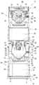
도 4는 본 발명의 실시예에 따른 제 2 송풍장치의 구성을 보여주는 분해 사시도이다.
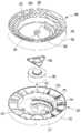
도 5는 본 발명의 실시예에 따른 제 3 에어가이드 장치 및 제 2 토출가이드 장치의 구성을 보여주는 분해 사시도이다.
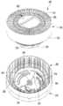
도 6은 본 발명의 실시예에 따른 유동 전환장치 및 상기 유동 전환장치가 결합되는 부품의 구성을 보여주는 분해 사시도이다.
도 7은 본 발명의 실시예에 따른 유동 전환장치의 구성을 보여주는 사시도이다.
도 8은 본 발명의 실시예에 따른 제 3 에어가이드 장치 및 제 2 토출가이드 장치의 결합모습을 보여주는 도면이다.
도 9는 본 발명의 실시예에 따른 유동 전환장치의 좌우방향 회전을 위하여 제 1 가이드기구가 작용하는 모습을 보여주는 도면이다.
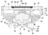
도 10은 본 발명의 실시예에 따른 유동 전환장치의 구성을 보여주는 단면도이다.
도 11은 본 발명의 실시예에 따른 유동 전환장치의 구성을 보여주는 분해 사시도이다.
도 12는 본 발명의 실시예에 따른 유동 전환장치의 구동부 및 고정부의 구성을 보여주는 분해 사시도이다.
도 13은 본 발명의 실시예에 따른 유동 전환장치에 구비되는 제 2 랙 및 제 2 기어의 연동모습을 보여주는 도면이다.
도 14 및 도 15는 본 발명의 실시예에 따른 유동 전환장치가 제 2 위치에 있는 모습을 보여주는 도면이다.
도 16은, 도 14의 유동 전환장치가 A 방향으로 회전한 모습을 보여주는 도면이다.
도 17은 본 발명의 실시예에 따른 토출그릴에 결합되는 디스플레이 장치의 구성을 보여주는 분해 사시도이다.
도 18은 본 발명의 실시예에 따른 토출그릴에 PCB 어셈블리가 결합되는 모습을 보여주는 도면이다.
도 19는 본 발명의 실시예에 따른 PCB 어셈블리의 구성을 보여주는 분해 사시도이다.
도 20은 본 발명의 실시예에 따른 디스플레이 장치의 상면 구성을 보여주는 도면이다.
도 21은 본 발명의 실시예에 따른 PCB 어셈블리의 저면 구성을 보여주는 도면이다.
도 22 내지 도 24는 본 발명의 실시예에 따른 공기 청정기에서의 공기유동 모습을 보여주는 도면이다.1 is a perspective view showing the appearance of an air purifier according to an embodiment of the present invention.
2 is a perspective view showing the internal configuration of an air purifier according to an embodiment of the present invention.
3 is a cross-sectional view taken along line III-III ′ of FIG. 2.
4 is an exploded perspective view showing the configuration of a second blower according to an embodiment of the present invention.
5 is an exploded perspective view showing the configuration of the third air guide device and the second discharge guide device according to an embodiment of the present invention.
Figure 6 is an exploded perspective view showing the configuration of the flow diverter and the component to which the flow diverter is coupled in accordance with an embodiment of the present invention.
7 is a perspective view showing the configuration of a flow diverter according to an embodiment of the present invention.
8 is a view showing a combination of the third air guide device and the second discharge guide device according to an embodiment of the present invention.
9 is a view showing the first guide mechanism for the left and right rotation of the flow switching device according to an embodiment of the present invention.
10 is a cross-sectional view showing the configuration of a flow diverter according to an embodiment of the present invention.
11 is an exploded perspective view showing the configuration of a flow diverter according to an embodiment of the present invention.
12 is an exploded perspective view showing the configuration of the drive unit and the fixing unit of the flow switching device according to an embodiment of the present invention.
13 is a view showing an interlocking view of the second rack and the second gear provided in the flow switching device according to an embodiment of the present invention.
14 and 15 are views showing a state in which the flow diverter according to an embodiment of the present invention in the second position.
FIG. 16 is a view illustrating a state in which the flow diverter of FIG. 14 is rotated in the A direction.
17 is an exploded perspective view showing the configuration of a display device coupled to a discharge grill according to an embodiment of the present invention.
18 is a view showing a PCB assembly coupled to the discharge grill according to an embodiment of the present invention.
19 is an exploded perspective view showing the configuration of a PCB assembly according to an embodiment of the present invention.
20 is a diagram illustrating a top configuration of a display device according to an embodiment of the present invention.
21 is a view showing a bottom configuration of a PCB assembly according to an embodiment of the present invention.
22 to 24 are views showing the state of air flow in the air purifier according to the embodiment of the present invention.
이하, 본 발명의 일부 실시 예들을 예시적인 도면을 통해 상세하게 설명한다. 각 도면의 구성요소들에 참조부호를 부가함에 있어서, 동일한 구성요소들에 대해서는 비록 다른 도면상에 표시되더라도 가능한 한 동일한 부호를 가지도록 하고 있음에 유의해야 한다. 또한, 본 발명의 실시 예를 설명함에 있어, 관련된 공지 구성 또는 기능에 대한 구체적인 설명이 본 발명의 실시 예에 대한 이해를 방해한다고 판단되는 경우에는 그 상세한 설명은 생략한다.Hereinafter, some embodiments of the present invention will be described in detail with reference to the accompanying drawings. In adding reference numerals to the components of each drawing, it should be noted that the same reference numerals are assigned to the same components as much as possible even though they are shown in different drawings. In addition, in describing the embodiments of the present invention, when it is determined that a detailed description of a related well-known configuration or function interferes with the understanding of the embodiments of the present invention, the detailed description thereof will be omitted.
또한, 본 발명의 실시 예의 구성 요소를 설명하는 데 있어서, 제 1, 제 2, A, B, (a), (b) 등의 용어를 사용할 수 있다. 이러한 용어는 그 구성 요소를 다른 구성 요소와 구별하기 위한 것일 뿐, 그 용어에 의해 해당 구성 요소의 본질이나 차례 또는 순서 등이 한정되지 않는다. 어떤 구성 요소가 다른 구성요소에 "연결", "결합" 또는 "접속"된다고 기재된 경우, 그 구성 요소는 그 다른 구성요소에 직접적으로 연결되거나 접속될 수 있지만, 각 구성 요소 사이에 또 다른 구성 요소가 "연결", "결합" 또는 "접속"될 수도 있다고 이해되어야 할 것이다.In addition, in describing the components of the embodiment of the present invention, terms such as first, second, A, B, (a), and (b) may be used. These terms are only for distinguishing the components from other components, and the nature, order or order of the components are not limited by the terms. If a component is described as being "connected", "coupled" or "connected" to another component, that component may be directly connected or connected to that other component, but between components It will be understood that may be "connected", "coupled" or "connected".
도 1은 본 발명의 실시예에 따른 공기 청정기의 외관을 보여주는 사시도이다.1 is a perspective view showing the appearance of an air purifier according to an embodiment of the present invention.
도 1을 참조하면, 본 발명의 실시예에 따른 공기 청정기(10)에는, 공기유동을 발생시키는 송풍장치(100,200) 및 상기 송풍장치(100,200)에서 발생된 공기유동의 토출방향을 전환시키는 유동 전환장치(300)가 포함된다.Referring to FIG. 1, in the
상기 송풍장치(100,200)에는, 제 1 공기유동을 발생시키는 제 1 송풍장치(100) 및 제 2 공기유동을 발생시키는 제 2 송풍장치(200)가 포함된다.The
상기 제 1 송풍장치(100)와 제 2 송풍장치(200)는 상하 방향으로 배열될 수 있다. 일례로, 상기 제 2 송풍장치(200)는 상기 제 1 송풍장치(100)의 상측에 배치될 수 있다. 이 경우, 상기 제 1 공기유동은, 상기 공기 청정기(10)의 하부측에 존재하는 실내공기를 흡입하는 유동을 형성하며, 상기 제 2 공기유동은, 상기 공기 청정기(10)의 상부측에 존재하는 실내공기를 흡입하는 유동을 형성한다.The
상기 공기 청정기(10)에는, 외관을 형성하는 케이스(101,201)가 포함된다.The
상세히, 상기 케이스(101,201)에는, 상기 제 1 송풍장치(100)의 외관을 형성하는 제 1 케이스(101)가 포함된다. 상기 제 1 케이스(101)는 원통형을 가질 수 있다. 그리고, 상기 제 1 케이스(101)의 상부는 하부보다 작은 직경을 가지도록 구성될 수 있다. 즉, 상기 제 1 케이스(101)는 끝부분이 잘린 원뿔형 형상을 가질 수 있다.In detail, the
상기 제 1 케이스(101)에는, 상기 제 1 케이스(101)를 구성하는 2개의 파트가 결합 또는 분리되는 제 1 분리부(101a)가 포함된다. 그리고, 상기 제 1 케이스(101)에는, 상기 제 1 분리부(101a)의 맞은편에 구비되는 힌지부(미도시)가 더 포함된다. 상기 2개의 파트는 상기 힌지부를 중심으로 상대 회전할 수 있다.The
상기 2개의 파트 중 적어도 어느 하나의 파트가 회전하면, 상기 제 1 케이스(101)는 개방되며, 상기 공기 청정기(10)로부터 분리될 수 있다. 상기 제 2 개의 파트가 결합되는 부분, 즉 상기 힌지부의 맞은편 측에는, 걸림장치가 구비될 수 있다. 상기 걸림장치에는, 걸림돌기 또는 자석부재가 포함될 수 있다. 상기 제 1 케이스(101)를 개방하여, 상기 제 1 송풍장치(100)의 내부 부품을 교체 또는 수리할 수 있다.When at least one of the two parts rotates, the
상기 제 1 케이스(101)에는, 공기가 흡입되는 제 1 흡입부(102)가 형성된다. 상기 제 1 흡입부(102)는 상기 제 1 케이스(101)의 적어도 일부분이 관통되어 형성되는 관통공을 포함한다. 상기 제 1 흡입부(102)는 다수 개가 형성된다.In the
상기 다수의 제 1 흡입부(102)는, 상기 제 1 케이스(101)를 기준으로 어느 방향에서라도 공기 흡입이 가능하도록, 상기 제 1 케이스(101)의 외주면을 따라 원주 방향으로 고르게 형성된다. 즉, 상기 제 1 케이스(101)의 내부중심을 지나는 상하방향의 중심선을 기준으로, 360도 방향에서 공기가 흡입될 수 있다.The plurality of
이와 같이, 상기 제 1 케이스(101)가 원통형으로 구성되고, 상기 제 1 흡입부(102)가 상기 제 1 케이스(101)의 외주면을 따라 다수 개 형성됨으로써, 공기의 흡입량이 증가할 수 있다. 그리고, 종래의 공기 청정기의 케이스와 같이, 모서리부를 가지는 육면체 형상을 회피함으로써, 흡입되는 공기에 대한 유동저항을 감소시킬 수 있다는 효과가 나타난다.As described above, since the
상기 제 1 흡입부(102)를 통하여 흡입되는 공기는 상기 제 1 케이스(101)의 외주면으로부터 대략 반경방향으로 유동될 수 있다. 방향을 정의한다. 도 1을 기준으로, 상하 방향을 축방향이라 이름하고, 가로 방향으로 반경방향으로 이름한다. 상기 축방향은, 후술할 제 1 팬(160) 및 제 2 팬(260)의 중심축 방향, 즉 팬의 모터축 방향에 대응될 수 있다. 그리고, 상기 반경방향은 상기 축방향의 수직한 방향으로서 이해될 수 있다.Air sucked through the
그리고, 원주방향이란, 상기 축방향을 중심으로 하고 상기 반경방향의 거리를 회전반경으로 하여 회전할 때 형성되는 가상의 원 방향으로서 이해된다.The circumferential direction is understood as an imaginary circular direction formed when the circumferential direction is rotated about the axial direction and the radial distance is rotated.
상기 제 1 송풍장치(100)에는, 상기 제 1 케이스(101)의 하측에 제공되며 지면에 놓여지는 베이스(20)가 더 포함된다. 상기 베이스(20)는, 상기 제 1 케이스(101)의 하단부로부터 하방으로 이격되어 위치된다. 그리고, 상기 제 1 케이스(101)와 상기 베이스(20) 사이의 이격 공간에는, 베이스흡입부(103)가 형성된다.The
상기 베이스흡입부(103)를 통하여 흡입되는 공기는 상기 베이스(20)의 상측에 구비되는 흡입그릴(110, 도 2 참조)의 흡입구(112)를 통하여 상방으로 유동될 수 있다.The air sucked through the
즉, 상기 제 1 송풍장치(100)에는, 복수의 흡입부(102,103)가 포함된다. 실내공간의 하부에 존재하는 공기는 상기 복수의 흡입부(102,103)를 통하여 상기 제 1 송풍장치(100)로 용이하게 유입될 수 있다. 따라서, 공기의 흡입량이 증가될 수 있다.That is, the
상기 제 1 송풍장치(100)의 상부에는, 제 1 토출부(105)가 형성된다. 상기 제 1 토출부(105)는, 상기 제 1 송풍장치(100)에 구비되는 제 1 토출가이드 장치(190, 도 2 참조)의 제 1 토출그릴(195)에 형성될 수 있다. 상기 제 1 토출가이드 장치(190)는 상기 제 1 송풍장치(100)의 상단부 외관을 형성한다. 상기 제 1 토출부(105)를 통하여 배출되는 공기는 축방향 상방으로 유동될 수 있다.The
상기 케이스(101,201)에는, 상기 제 2 송풍장치(200)의 외관을 형성하는 제 2 케이스(201)가 포함된다. 상기 제 2 케이스(201)는 원통형을 가질 수 있다. 그리고, 상기 제 2 케이스(201)의 상부는 하부보다 작은 직경을 가지도록 구성될 수 있다. 즉, 상기 제 2 케이스(201)는 끝부분이 잘린 원뿔형 형상을 가질 수 있다.The
상기 제 2 케이스(201)에는, 제 2 분리부(201a)를 통하여 분리 또는 결합될 수 있는 2개의 파트 및 힌지부가 포함된다. 상기 제 2 케이스(201)는, 상기 제 1 케이스(101)와 마찬가지로 개방 가능하게 구성될 수 있다. 자세한 설명은, 상기 제 1 케이스(101)에 관한 설명을 원용한다. 상기 제 2 케이스(201)를 개방하여, 상기 제 2 송풍장치(200)의 내부 부품을 교체 또는 수리할 수 있다.The
상기 제 2 케이스(201)의 하단부 직경은, 상기 제 1 케이스(101)의 상단부 직경보다 작게 형성될 수 있다. 따라서, 상기 케이스(101,201)의 전체적인 형상 관점에서, 케이스(101,201)의 하부 단면적은 상부 단면적 보다 크게 형성되며, 이에 따라 상기 공기 청정기(10)는 지면에 안정적으로 지지될 수 있다.The lower end diameter of the
상기 제 2 케이스(201)에는, 공기가 흡입되는 제 2 흡입부(202)가 형성된다. 상기 제 2 흡입부(202)는 상기 제 2 케이스(201)의 적어도 일부분이 관통되어 형성되는 관통공을 포함한다. 상기 제 2 흡입부(202)는 다수 개가 형성된다.The
상기 다수의 제 2 흡입부(202)는, 상기 제 2 케이스(201)를 기준으로 어느 방향에서라도 공기 흡입이 가능하도록, 상기 제 2 케이스(201)의 외주면을 따라, 원주 방향으로 고르게 형성된다. 즉, 상기 제 2 케이스(201)의 내부중심을 지나는 상하방향의 중심선을 기준으로, 360도 방향에서 공기가 흡입될 수 있다.The plurality of
이와 같이, 상기 제 2 케이스(201)가 원통형으로 구성되고, 상기 제 2 흡입부(202)가 상기 제 2 케이스(201)의 외주면을 따라 다수 개 형성됨으로써, 공기의 흡입량이 증가할 수 있다. 그리고, 종래의 공기 청정기의 케이스와 같이, 모서리부를 가지는 육면체 형상을 회피함으로써, 흡입되는 공기에 대한 유동저항을 감소시킬 수 있다는 효과가 나타난다.As described above, since the
상기 제 2 흡입부(202)를 통하여 흡입되는 공기는 상기 제 2 케이스(201)의 외주면으로부터 대략 반경방향으로 유동될 수 있다.Air sucked through the
상기 공기 청정기(10)에는, 상기 제 1 송풍장치(100)와 상기 제 2 송풍장치(200)의 사이에 구비되는 구획장치(400)가 포함된다. 상기 구획장치(400)에 의하여, 상기 제 2 송풍장치(200)는 상기 제 1 송풍장치(100)의 상측으로 이격되어 위치될 수 있다. 상기 구획장치(400)와 관련된 설명은, 도면을 참조하여 후술한다.The
상기 유동 전환장치(300)는 상기 제 2 송풍장치(200)의 상측에 설치될 수 있다. 공기 유동을 기준으로, 상기 제 2 송풍장치(200)의 공기유로는, 상기 유동 전환장치(300)의 공기유로와 연통될 수 있다. 상기 제 2 송풍장치(200)를 통과한 공기는 상기 유동 전환장치(300)의 공기유로를 경유하며, 제 2 토출부(305)를 통하여 외부로 배출될 수 있다. 상기 제 2 토출부(305)는 상기 유동 전환장치(300)의 상단부에 형성된다.The
상기 유동 전환장치(300)는 움직임 가능하게 구비될 수 있다. 상세히, 상기 유동 전환장치(300)는, 도 1에 도시되어 있는 바와 같이, 누워있는 상태(제 1 위치)에 있거나, 도 24에 도시되는 바와 같이, 경사지게 세워진 상태(제 2 위치)에 있을 수 있다.The
그리고, 상기 유동 전환장치(300)의 상부에는, 공기 청정기(10)의 운전 정보를 표시하는 디스플레이 장치(600)가 구비된다. 상기 디스플레이 장치(600)는 상기 유동 전환장치(300)와 함께 움직일 수 있다.In addition, a
도 2는 본 발명의 실시예에 따른 공기 청정기의 내부 구성을 보여주는 사시도이고, 도 3은 도 2의 III-III'를 따라 절개한 단면도이다.2 is a perspective view illustrating an internal configuration of an air cleaner according to an embodiment of the present invention, and FIG. 3 is a cross-sectional view taken along line III-III 'of FIG. 2.
도 2 및 도 3을 참조하면, 본 발명의 실시예에 따른 제 1 송풍장치(100)에는, 베이스(20) 및 상기 베이스(20)의 상측에 배치되는 흡입그릴(110)이 포함된다.2 and 3, the
상기 베이스(20)에는, 지면에 놓여지는 베이스본체(21) 및 상기 베이스본체(21)로부터 상방으로 돌출되어 상기 흡입그릴(110)이 놓여지는 베이스돌출부(22)가 포함된다. 상기 베이스돌출부(22)는 상기 베이스(20)의 양측에 구비될 수 있다.The
상기 베이스돌출부(22)에 의하여, 상기 베이스본체(21)와 상기 흡입그릴(110)은 서로 이격된다. 상기 베이스(20)와 상기 흡입그릴(110)의 사이에는, 공기의 흡입공간을 형성하는 베이스흡입부(103)가 형성된다.By the
상기 흡입그릴(110)에는, 대략 링 형상의 그릴본체(111) 및 상기 그릴본체(111)의 외주면으로부터 상방으로 돌출되는 테두리부가 포함된다. 상기 그릴본체(111) 및 테두리부의 구성에 의하여, 상기 흡입그릴(110)은 단차진 구성을 가질 수 있다.The
상기 흡입그릴(110)에는, 상기 테두리부에 형성되는 흡입부(112)가 포함된다. 상기 흡입부(112)는 상기 테두리부의 둘레를 따라 상방으로 돌출되도록 구성되며, 원주 방향으로 연장되도록 구성될 수 있다. 그리고, 상기 흡입부(112)의 내부에는, 다수 개의 흡입공(112a)이 형성된다. 상기 다수 개의 흡입공(112a)은 상기 베이스흡입부(103)와 연통될 수 있다.The
상기 다수 개의 흡입공(112a) 및 상기 베이스흡입부(103)를 통하여 흡입된 공기는 제 1 펄터부재(120)를 통과할 수 있다. 상기 제 1 필터부재(120)는 원통형으로 구비되며, 공기를 필터링 하는 필터면을 가질 수 있다. 상기 다수 개의 흡입공(112a)을 통과한 공기는 원통형인 제 1 필터부재(120)의 외주면을 관통하여 그 내부로 유입될 수 있다.Air sucked through the plurality of
상기 제 1 송풍장치(100)에는, 상기 제 1 필터부재(120)의 장착공간을 형성하는 제 1 필터프레임(130)이 더 포함된다. 상세히, 상기 제 1 필터프레임(130)에는, 상기 제 1 필터프레임(130)의 하부를 형성하는 제 1 프레임(131) 및 상기 제 1 필터프레임(130)의 상부를 형성하는 제 2 프레임(132)이 포함된다. 상기 제 1,2 프레임(131,132)는 대략 링 형상을 가질 수 있다.The
상기 제 1 필터프레임(130)에는, 상기 제 1 프레임(131)으로부터 상기 제 2 프레임(132)을 향하여 상방으로 연장되는 제 1 필터지지부(135)가 더 포함된다. 상기 제 1 필터지지부(135)는 다수 개가 제공되며, 상기 다수 개의 제 1 필터지지부(135)는 원주 방향으로 배열되어 상기 제 1,2 프레임(131,132)의 테두리부에 연결될 수 있다.The
상기 제 1,2 프레임(131,132) 및 상기 다수의 제 1 필터지지부(135)에 의하여, 상기 제 1 필터부재(120)의 장착공간이 규정된다. 그리고, 상기 제 1 필터지지부(135)의 외측에는, 제 1 지지부커버(136)가 결합될 수 있다.The mounting space of the
상기 제 1 필터프레임(130)에는, 센서장치(137)가 설치될 수 있다. 상기 센서장치(137)에는, 공기 중 먼지의 양을 감지하는 먼지센서 및 공기 중 가스의 양을 감지하는 가스센서가 포함될 수 있다. 상기 먼지센서 및 가스센서는 상기 제 1 필터프레임(130)의 제 2 프레임(132)에 지지되도록 배치될 수 있다.The
상기 장착공간에는, 상기 제 1 필터부재(120)가 분리 가능하게 장착될 수 있다. 상기 제 1 필터부재(120)는 원통형의 형상을 가지며, 상기 제 1 필터부재(120)의 외주면을 통하여 공기가 유입될 수 있다. 상기 제 1 필터부재(120)를 통과하는 과정에서, 공기 중 미세먼지와 같은 불순물이 걸러질 수 있다.In the mounting space, the
상기 제 1 필터부재(120)가 원통형의 형상을 가짐으로써, 상기 제 1 필터부재(120)를 기준으로, 어느 방향에서나 공기의 유입이 가능하다. 따라서, 공기의 필터링 면적이 증가할 수 있다.Since the
상기 장착공간은 상기 제 1 필터부재(120)의 형상에 대응하여 원통형으로 구비될 수 있다. 상기 제 1 필터부재(120)는 장착과정에서, 상기 장착공간을 향하여 슬라이딩 가능하게 인입될 수 있다. 반대로, 상기 제 1 필터부재(120)는 분리 과정에서, 상기 장착공간으로부터 슬라이딩 가능하게 인출될 수 있다.The mounting space may be provided in a cylindrical shape corresponding to the shape of the
상기 제 1 송풍장치(100)에는, 상기 제 1 필터부재(120)의 출구측에 설치되는 제 1 팬하우징(150)이 더 포함된다. 상기 제 1 팬하우징(150)에는, 제 1 팬(160)이 수용되는 하우징공간부(152)가 형성된다. 그리고, 상기 제 1 팬하우징(150)은 상기 제 1 필터프레임(130)에 의하여 지지될 수 있다.The
상기 제 1 팬하우징(150)의 하부에는, 상기 제 1 팬하우징(150)의 내부로 공기의 유입을 가이드 하는 제 1 팬유입부(151)가 포함된다. 상기 제 1 팬유입부(151)에는 그릴이 제공되어, 상기 제 1 필터부재(150)가 분리되었을 때, 사용자가 상기 제 1 팬하우징(150)의 내부로 손가락등을 집어 넣는 것을 방지할 수 있다.A lower part of the
상기 제 1 송풍장치(100)에는, 공기 중 냄새입자를 제거하거나 살균하기 위한 이오나이저가 더 포함된다. 상기 이오나이저는 상기 제 1 팬하우징(150)에 결합되며, 상기 제 1 팬하우징(150)의 내부를 유동하는 공기에 작용할 수 있다.The
상기 센서장치(137)와 상기 이오나이저는 후술할 제 2 송풍장치(200)에도 설치될 수 있다. 다른 예로서, 상기 센서장치(137)와 상기 이오나이저는 상기 제 1 송풍장치(100) 및 제 2 송풍장치(200) 중 하나의 송풍장치에 설치될 수도 있다.The
상기 제 1 팬(160)은 상기 제 1 팬유입부(151)의 상측에 놓여진다. 일례로, 상기 제 1 팬(160)에는, 축방향으로 공기를 유입하여 반경방향 상측으로 공기를 배출시키는 원심팬이 포함된다.The
상세히, 상기 제 1 팬(160)에는, 원심팬 모터인 제 1 팬모터(165)의 회전축(165a)이 결합되는 허브(161)와, 상기 허브(161)와 이격되어 배치되는 쉬라우드(162) 및 상기 허브(161)와 상기 쉬라우드(162)의 사이에 배치되는 다수의 블레이드(163)가 포함된다. 상기 제 1 팬모터(165)는 상기 제 1 팬(160)의 상측에 결합될 수 있다.In detail, the
상기 허브(161)는 하방으로 갈수록 직경이 좁아지는 보울(bowl) 형상을 가질 수 있다. 그리고, 상기 허브(161)에는, 상기 회전축(165a)이 결합되는 축 결합부 및 상기 축 결합부로부터 상방을 향햐여 경사지게 연장되는 제 1 블레이드결합부가 포함된다.The
상기 쉬라우드(162)에는, 상기 제 1 팬유입부(151)를 통과한 공기가 흡입되는 쉬라우드흡입구가 형성되는 하단부 및 상기 하단부로부터 상방을 향하여 연장되는 제 2 블레이드결합부가 포함된다.The
상기 블레이드(163)의 일면은 상기 허브(161)의 제 1 블레이드결합부에 결합되며, 타면은 상기 쉬라우드(162)의 제 2 블레이드결합부에 결합될 수 있다. 그리고, 상기 다수의 블레이드(163)는 상기 허브(161)의 원주 방향으로 이격되어 배치될 수 있다.One surface of the
상기 제 1 송풍장치(100)에는, 상기 제 1 팬(160)의 상측에 결합되어 상기 제 1 팬(160)을 통과한 공기의 유동을 가이드 하는 제 1 에어가이드장치(170)가 더 포함된다.The
상기 제 1 에어가이드 장치(170)에는, 원통형의 형상을 가지는 외벽(171) 및 상기 외벽(171)의 내측에 위치되며 원통형의 형상을 가지는 내벽(172)이 포함된다. 상기 외벽(171)은 상기 내벽(172)을 둘러싸도록 배치된다. 상기 외벽(171)의 내주면과, 상기 내벽(172)의 외주면의 사이에는, 공기가 유동하는 제 1 공기유로가 형성된다.The first
상기 제 1 에어가이드 장치(170)에는, 상기 제 1 공기유로에 배치되는 가이드 리브(175)가 포함된다. 상기 가이드 리브(175)는 상기 내벽(172)의 외주면으로부터 상기 외벽(171)의 내주면으로 연장된다. 상기 가이드 리브(175)는 다수 개가 이격되어 배치될 수 있다. 상기 다수의 가이드 리브(175)는 상기 제 1 팬(160)을 거쳐 상기 제 1 에어가이드 장치(170)의 제 1 공기유로로 유입된 공기를 상방으로 안내하는 기능을 수행한다.The first
상기 가이드 리브(175)는, 상기 외벽(171) 및 내벽(172)의 하부로부터 상방을 향하여 경사지게 연장될 수 있다. 일례로, 상기 가이드 리브(175)는 라운드지게 형성되어, 공기가 상방으로 경사지게 유동할 수 있도록 가이드 한다.The
상기 제 1 에어가이드 장치(170)에는, 상기 내벽(172)으로부터 하방으로 연장되어 상기 제 1 팬모터(165)를 수용하는 모터 수용부(173)가 더 포함된다. 상기 모터 수용부(173)는 하부로 갈수록 직경이 작아지는 보울(bowl)의 형상을 가질 수 있다. 상기 모터 수용부(173)의 형상은, 상기 허브(161)의 형상에 대응될 수 있다. 그리고, 상기 모터 수용부(173)는 상기 허브(161)의 내측에 삽입될 수 있다.The first
싱기 제 1 팬모터(165)는 상기 모터 수용부(173)의 상측에 지지될 수 있다. 그리고, 상기 제 1 팬모터(165)의 회전축(165a)은 상기 제 1 팬모터(165)로부터 하방으로 연장되며, 상기 모터 수용부(173)의 저면부을 관통하여 상기 허브(161)의 축 결합부에 결합될 수 있다.The
상기 제 1 송풍장치(100)에는, 상기 제 1 에어가이드 장치(170)의 상측에 결합되며 상기 제 1 에어가이드 장치(170)를 통과한 공기를 제 1 토출가이드 장치(190)로 가이드 하는 제 2 에어가이드 장치(180)가 더 포함된다.The
상기 제 2 에어가이드 장치(180)에는, 대략 원통형의 형상을 가지는 제 1 가이드벽(181)과, 상기 제 1 가이드벽(181)의 내측에 위치되며 대략 원통형의 형상을 가지는 제 2 가이드벽(182)이 포함된다. 상기 제 1 가이드벽(181)은 상기 제 2 가이드 벽(182)을 둘러싸도록 배치될 수 있다.The second
상기 제 1 가이드벽(181)의 내주면과 상기 제 2 가이드벽(182)의 외주면 사이에는, 공기가 유동하는 제 2 공기유로가 형성된다. 상기 제 1 에어가이드 장치(170)의 제 1 공기유로를 유동하는 공기는 상기 제 2 공기유로를 거쳐 통과하여 상방으로 유동한다. 상기 제 2 공기유로(185)를 "토출유로"라 이름할 수 있다. 그리고, 상기 제 2 공기유로의 상측에는, 제 1 토출부(105)가 배치된다.A second air passage through which air flows is formed between the inner circumferential surface of the
원통형의 형상을 가지는 제 2 가이드벽(182)의 내측에는, PCB 장치(500)의 적어도 일부분이 수용되는 제 1 공간부가 형성된다. 상기 PCB 장치에는, 전원 공급부(520) 및 메인 PCB(511)가 포함된다.Inside the
상기 전원 공급부(520)는, 공기 청정기(10)에 연결되는 전원선으로부터 공급되는 상용전원을 인가받아, 상기 메인 PCB(511) 및 공기 청청기(10) 내의 다수의 부품에 전원을 공급하는 장치로서 이해된다. 상기 전원 공급부(520)에는, AC전원용 PCB(파워 PCB)가 포함될 수 있다.The
상기 메인 PCB(511)에는, 상기 AC전원용 PCB에서 변환된 직류 전압에 의하여 구동되는 DC전원용 PCB가 포함될 수 있다.The
상기 PCB 장치(500)에는, 상기 전원 공급부(520) 및 메인 PCB(511)를 지지하는 위한 PCB지지판(525)이 더 포함된다. 상기 메인 PCB(511)는 상기 PCB지지판(525)의 일면에 지지되고, 상기 전원 공급부(520)는 상기 PCB지지판(525)의 타면에 지지될 수 있다.The
상기 PCB 장치에는, 공기 청정기(10)가 외부 장치와 통신할 수 있는 통신모듈(515)이 포함된다. 일례로, 상기 통신모듈(515)에는, 와이파이 모듈이 포함될 수 있다. 상기 통신모듈(515)은 상기 PCB지지판(525)에 지지되며, 상기 메인 PCB(511)의 하측에 배치될 수 있다.The PCB device includes a
상기 제 1 송풍장치(100)에는, 상기 제 2 에어가이드장치(180)의 상측, 즉 공기유로를 기준으로, 상기 제 2 에어가이드장치(180)를 통과하는 공기유동의 출구측에 배치되며, 공기 청정기(10) 외부로의 공기 토출을 가이드 하는 제 1 토출가이드 장치(190)가 더 포함된다. 상기 제 1 토출가이드 장치(190)에는, 공기가 배출되는 제 1 토출부(105)가 형성된다.The
상기 제 2 송풍장치(200)에는, 제 2 필터부재(220)와, 상기 제 2 필터부재(220)의 하부를 지지하는 지지장치(240) 및 상기 지지장치(240)의 하측에 제공되어 상기 제 2 필터부재(220) 및 상기 지지장치(240)를 지지하는 레버장치(242)가 포함된다(도 4 참조).The
상기 제 2 송풍장치에는, 상기 레버장치(242)를 지지하는 레버 지지장치(560)가 더 포함된다. 상기 레버 지지장치(560)는 대략 환형의 형상을 가진다. 상기 레버 지지장치(560)에는, 상기 PCB 장치(500)가 위치될 수 있는 설치공간을 정의하는 제 3 공간부가 포함된다. 상기 제 3 공간부는 상기 레버 지지장치(560)의 대략 중앙부에 형성된다.The second blower further includes a
상기 제 1 송풍장치(100)와 상기 제 2 송풍장치(200)의 사이에는, 구획장치(400)가 구비된다. 상기 구획장치(400)에는, 상기 제 1 송풍장치(100)에서 발생되는 공기유동과, 상기 제 2 송풍장치(200)에서 발생되는 공기유동을 분리 또는 차단하기 위한 구획판(430)이 포함된다. 상기 구획판(430)에 의하여, 상기 제 1,2 송풍장치(100,200)는 상하 방향으로 이격되어 배치될 수 있다.A
즉, 상기 제 1,2 송풍장치(100,200)의 사이에는, 상기 구획판(430)이 위치하는 이격공간이 형성된다. 상기 이격공간의 하단부에는 상기 제 1 송풍장치(100)의 제 1 토출가이드 장치(190)가 위치하며, 상기 이격공간의 상단부에는 상기 제 2 송풍장치(200)의 레버 지지장치(560)가 위치될 수 있다.That is, the separation space in which the
상기 이격공간은, 상기 구획판(430)에 의하여, 상부공간 및 하부공간으로 구획될 수 있다. 상기 하부공간은, 상기 제 1 토출가이드 장치(190)의 제 1 토출부(105)에서 배출되는 공기가 공기 청정기(10)의 외부로 유동되는 과정에서 경유되는 제 1 공간부(448)으로서 이해된다. 그리고, 상기 상부공간은, 사용자가 공기 청정기(10)를 이동할 때 손을 집어 넣을 수 있는 파지공간으로서 제 2 공간부(458)를 구성한다.The separation space may be partitioned into an upper space and a lower space by the
상기 제 1 토출부(105)에서 배출되는 공기는 상기 구획판(430)에 의하여 가이드 되어 상기 공기 청정기(10)의 외부로 유동하며, 상기 제 2 송풍장치(200)측으로 유입되는 것이 방지될 수 있다.Air discharged from the
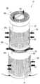
도 4는 본 발명의 실시예에 따른 제 2 송풍장치의 구성을 보여주는 분해 사시도이다.4 is an exploded perspective view showing the configuration of a second blower according to an embodiment of the present invention.
도 4를 참조하면, 본 발명의 실시예에 따른 제 2 송풍장치(200)에는, 레버 지지장치(560), 레버장치(242), 지지장치(240), 제 2 필터부재(220), 제 2 필터프레임(230), 제 2 팬하우징(250) 및 제 2 팬(260)이 포함된다.Referring to FIG. 4, the
상기 제 2 필터부재(220)는 상부가 개구된 원통 형상을 가질 수 있다. 상기 제 2 필터부재(220)에는, 내부가 비어 있는 원통 형상의 필터부를 가지는 필터본체(221) 및 상기 필터본체(221)의 상단부에 개구되어 형성되는 필터공(222)이 포함된다. 상기 필터본체(221)의 상부 또는 하부에는, 필터파지부(221a)가 구비된다. 공기는 상기 필터본체(221)의 외주면을 통하여 상기 필터본체(221)의 내측으로 유입되며, 상기 필터공(222)을 통하여 상기 제 2 필터부재(220)로부터 배출될 수 있다. 상기 제 2 필터부재(220)의 구성은, 상기 제 1 필터부재(120)에도 원용될 수 있다.The
상기 레버 지지장치(560)에는, 환형의 형상을 가지는 레버 지지본체(561)가 포함된다. 상기 레버 지지본체(561)는, 그 내주면으로부터 외주면을 향하여 축방향에 대하여, 상방으로 약간 경사지게 연장된다. 즉, 상기 레버 지지본체(561)를 구성하는 면은 경사면을 구성한다. 상기 경사면과, 상기 구획판(430)의 상면 사이의 공간은, 사용자의 손이 위치할 수 있는 제 2 공간부(458)를 제공한다.The
한편, 상기 레버 지지본체(561)는, 상기 제 1 송풍장치(100)의 제 1 토출부(105)를 통하여 배출된 공기가 상기 제 2 송풍장치(200)로 유입되는 것을 차단하는 점에서, "차단부"라 이름할 수도 있다.On the other hand, the
상기 레버 지지장치(560)에는, 상기 레버 지지본체(561)로부터 상방으로 돌출되는 이동 가이드부(565)가 더 포함된다. 상기 이동 가이드부(565)는 상기 레버 지지본체(561)의 원주 방향으로 다수 개가 이격되어 배치될 수 있다. 그리고, 상기 레버 지지장치(560)에는, 상기 레버 지지본체(5610의 내주면으로부터 상방으로 돌출되는 지지턱(566)이 더 포함된다. 상기 지지턱(566)은, 상기 제 2 송풍장치(200)의 레버장치를 지지한다.The
상기 레버장치(242)는, 사용자의 조작이 가능하도록 구비될 수 있다. 일례로, 상기 레버장치(242)는 원주 방향으로 회전 가능하도록 구비될 수 있다.The
상기 레버장치(242)에는, 대략 링 형상을 가지며 회전 가능하게 구비되는 레버본체(243)가 포함된다. 그리고, 상기 레버본체(243)에는, 상기 다수의 이동 가이드부(565)에 대응되는 위치에 배치되는 다수의 절개부(145)가 형성된다. 상기 다수의 절개부(145)는, 상기 레버본체(243)에 형성되는 관통공으로서 이해될 수 있다.The
상기 다수의 절개부(245)는 서로 이격되어, 상기 레버본체(243)의 원주 방향으로 배열된다. 그리고, 각 절개부(245)는 레버본체(243)의 외주면 곡률에 대응하여, 원주 방향으로 소정의 곡률을 가지도록 라운드지게 형성될 수 있다.The plurality of
상기 레버장치(142)는 상기 레버 지지본체(561)의 상면에 지지된다. 상기 레버장치(242)가 상기 레버 지지본체(561)에 지지되면, 상기 다수 개의 이동 가이드부(565)는 상기 다수 개의 절개부(245)에 삽입되도록 배치될 수 있다. 상세히, 상기 다수 개의 이동 가이드부(565)는 상기 다수 개의 절개부(245)를 관통하여, 상기 다수 개의 절개부(245)의 상측으로 돌출될 수 있다.The lever device 142 is supported on the upper surface of the
상기 각 절개부(245)의 길이는, 상기 이동 가이드부(565)의 길이보다 길게 형성될 수 있다. 따라서, 상기 이동 가이드부(565)가 상기 절개부(245)에 삽입된 상태에서, 상기 레버장치(242)는 회전될 수 있다. 그리고, 상기 레버장치(242)가 일방향으로 회전하는 과정에서 상기 이동 가이드부(565)의 일측 단부는 상기 절개부(245)의 일측 단부에 간섭될 수 있고, 타방향으로 회전되는 과정에서 상기 이동 가이드부(565)의 타측 단부는 상기 절개부(245)의 타측 단부에 간섭될 수 있다.The length of each
상기 레버본체(243)의 외주면에는, 제 2 핸들(244)이 구비된다.On the outer circumferential surface of the
상기 레버장치(242)의 상측에는, 상기 제 2 필터부재(220)를 지지하는 지지장치(240)가 제공된다. 상기 지지장치(240)에는, 상기 제 2 핸들(244)에 결합되는 제 1 핸들(241)이 포함된다. 사용자는, 상기 제 1,2 핸들(241,244)을 파지하여 상기 레버본체(143) 및 지지장치(140)를 시계방향 또는 반시계 방향으로 회전시킬 수 있다.On the upper side of the
상기 레버장치(242)는 상기 지지장치(240)의 하면을 지지한다. 상기 지지장치(240)에는, 상기 이동 가이드부(565)와 접촉하는 지지 돌출부(미도시)가 구비될 수 있다. 상기 지지 돌출부는 상기 지지장치(240)의 하면으로부터 하방으로 돌출되며, 상기 이동 가이드부(565)에 대응하는 위치에 구비될 수 있다. 그리고, 상기 지지 돌출부의 형상은 상기 이동 가이드부(565)의 형상에 대응되며, 원주 방향으로 점점 돌출되도록 형성되는 경사면이 포함된다.The
상기 이동 가이드부(565)가 점점 돌출되도록 형성되는 방향과, 상기 지지 돌출부가 점점 돌출되도록 형성되는 방향은 서로 반대일 수 있다. 일례로, 상기 이동 가이드부(565)가 점점 돌출되도록 구성되는 방향이 반시계방향이라면, 상기 지지 돌출부가 점점 돌출되도록 구성되는 방향은 시계방향일 수 있다.The direction in which the
상기 지지 돌출부는 상기 절개부(245)와 대응되는 위치에 배치될 수 있다. 즉, 상기 이동 가이드부(565)와 상기 지지 돌출부는 상기 절개부(145)에 삽입되는 위치에 배치될 수 있다.The support protrusion may be disposed at a position corresponding to the
상기 레버장치(242)와 상기 지지장치(240)는 함께 회전될 수 있다. 이 회전 과정에서, 상기 이동 가이드부(565)와 상기 지지 돌출부는 간섭될 수 있다. 상세히, 상기 지지 돌출부의 하부와 상기 이동 가이드부(565)의 상부가 맞닿으면, 상기 레버장치(242)와 상기 지지장치(240)는 상방으로 들어올려진다. 그리고, 상기 지지장치(240)에 의하여 지지되는 제 1 필터부재(220)는 상방으로 이동하면서 상기 제 1 송풍장치(200)에 결합된 상태에 있게 된다.The
반면에, 상기 지지 돌출부의 상부와 상기 이동 가이드부(565)의 하부가 맞닿거나 상기 지지 돌출부와 이동 가이드부(565)의 간섭이 해제되면, 상기 레버장치(242)와 상기 지지장치(240)는 하방으로 내려온다. 그리고, 상기 지지장치(240)에 의하여 지지되는 제 1 필터부재(220)는 상기 제 1 송풍장치(100)로부터 분리 가능한 상태(해제 상태)에 있게 된다.On the other hand, when the upper portion of the support protrusion and the lower portion of the
상기 제 2 송풍장치(200)에는, 상기 제 2 필터부재(220)의 장착공간을 형성하는 제 2 필터프레임(230)이 더 포함된다. 상세히, 상기 제 2 필터프레임(230)에는, 상기 제 1 필터프레임(230)의 하부를 형성하는 제 1 프레임(231) 및 상기 제 2 필터프레임(230)의 상부를 형성하는 제 2 프레임(232)이 포함된다.The
상기 제 1 프레임(231)에는, 하방으로 함몰되는 형상을 가지는 프레임함몰부(231a)가 포함된다. 상기 프레임함몰부(231a)는 상기 제 1 프레임(231)의 적어도 일부분이 함몰되도록 구성될 수 있다. 상기 홈부(114)는, 상기 제 1,2 핸들(241,244)이 움직일 수 있는 공간부를 제공한다. 상기 제 1,2 핸들(241,244)은 상기 공간부에 위치하여, 시계방향 또는 반시계 방향으로 회전될 수 있다.The
상기 제 2 프레임(232)은 상기 제 1 프레임(231)으로부터 상방으로 이격되어 위치된다. 상기 제 2 프레임(232)은 대략 링 형상을 가진다. 상기 제 2 프레임(232)의 링 형상의 내부 공간은, 상기 제 2 필터프레임(230)을 통과하는 공기유로의 적어도 일부분을 형성한다. 그리고, 상기 제 2 프레임(232)의 상부는 제 2 팬하우징(250)을 지지할 수 있다.The
상기 제 2 필터프레임(230)에는, 상기 제 1 프레임(231)으로부터 상기 제 2 프레임(232)을 향하여 상방으로 연장되는 제 2 필터지지부(235)가 더 포함된다. 상기 제 2 필터지지부(235)에 의하여, 상기 제 1,2 프레임(231,232)은 서로 이격될 수 있다. 상기 제 2 필터지지부(235)는 다수 개가 제공되며, 상기 다수 개의 제 2 필터지지부(235)는 원주 방향으로 배열되어 상기 제 1,2 프레임(231,232)의 테두리부에 연결될 수 있다.The
상기 제 1,2 프레임(231,232) 및 상기 다수의 제 2 필터지지부(235)에 의하여, 상기 제 2 필터부재(220)의 장착공간이 규정된다. 그리고, 상기 제 2 필터지지부(235)의 외측에는, 제 1 지지부커버(236)가 결합될 수 있다.The mounting space of the
상기 제 2 필터프레임(230)에는, 제 2 센서장치(237)가 설치될 수 있다. 상기 센서장치(237)에는, 공기 중 먼지의 양을 감지하는 먼지센서(237a) 및 공기 중 가스의 양을 감지하는 가스센서(237b)가 포함될 수 있다. 상기 먼지센서(237a) 및 가스센서(237b)는 상기 제 2 필터프레임(230)의 제 2 프레임(232)에 지지되도록 배치될 수 있다. 상기 제 2 센서장치(237)의 구성에 관한 설명은, 상기 제 1 센서장치(137)에도 적용될 수 있다.The
상기 장착공간에는, 상기 제 2 필터부재(220)가 분리 가능하게 장착될 수 있다. 상기 제 1 필터부재(220)는 원통형의 형상을 가지며, 상기 제 2 필터부재(220)의 외주면을 통하여 공기가 유입될 수 있다. 상기 제 2 필터부재(220)를 통과하는 과정에서, 공기 중 미세먼지와 같은 불순물이 걸러질 수 있다.The
상기 제 1 필터부재(220)가 원통형의 형상을 가짐으로써, 상기 제 1 필터부재(220)를 기준으로, 어느 방향에서나 공기의 유입이 가능하다. 따라서, 공기의 필터링 면적이 증가할 수 있다.Since the
상기 장착공간은 상기 제 1 필터부재(220)의 형상에 대응하여 원통형으로 구비될 수 있다. 상기 제 1 필터부재(220)는 장착과정에서, 상기 장착공간을 향하여 슬라이딩 가능하게 인입될 수 있다. 반대로, 상기 제 2 필터부재(220)는 분리 과정에서, 상기 장착공간으로부터 슬라이딩 가능하게 인출될 수 있다.The mounting space may be provided in a cylindrical shape corresponding to the shape of the
달리 말하면, 상기 제 1 필터부재(220)가 상기 지지장치(240)의 상면에 놓여진 상태에서 상기 제 1,2 핸들(241,244)이 조작되면, 상기 제 2 필터부재(220)는 하방으로 이동하면서 해제위치에 있게 된다. 그리고, 상기 제 2 필터부재(220)는 반경방향 외측으로 슬라이딩 되어, 상기 장착공간으로부터 분리될 수 있다.In other words, when the first and
반면에, 상기 제 2 필터부재(220)는 상기 장착공간으로부터 분리된 상태에서, 상기 장착공간을 향하여 반경방향 내측으로 슬라이딩 되어 상기 지지장치(240)의 상면에 지지되며, 상기 제 1,2 핸들(241,244)의 조작에 의하여 상방으로 밀착될 수 있다. 이 때, 상기 제 1 필터부재(220)는 상기 제 1 송풍장치(200)로의 결합위치에 있게 된다.On the other hand, in the state in which the
상기 제 2 송풍장치(200)에는, 상기 제 2 필터부재(220)의 출구측에 설치되는 제 2 팬하우징(250)이 더 포함된다. 상기 제 2 팬하우징(250)에는, 제 2 팬(260)이 수용되는 하우징공간부(252)가 형성된다. 상기 제 2 팬하우징(250) 및 상기 제 2 팬(260)의 구성은 상기 제 1 팬하우징(150) 및 제 1 팬(160)의 구성과 동일하므로, 상기 제 2 팬하우징(250) 및 상기 제 2 팬(260)에 관한 설명은 상기 제 1 팬하우징(150) 및 제 1 팬(160)에 관한 설명을 원용한다.The
상기 제 2 송풍장치(200)에는, 공기 중 냄새입자를 제거하거나 살균하기 위한 이오나이저(258)가 더 포함된다. 상기 이오나이저(258)는 상기 제 1 팬하우징(250)에 결합되며, 상기 제 2 팬하우징(250)의 내부를 유동하는 공기에 작용할 수 있다. 상기 이오나이저(258)은 상기 제 1 송풍장치(100)의 이오나이저와 동일한 구성을 가질 수 있다.The
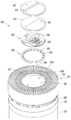
도 5는 본 발명의 실시예에 따른 제 3 에어가이드 장치 및 제 2 토출가이드 장치의 구성을 보여주는 분해 사시도이고, 도 6은 본 발명의 실시예에 따른 유동 전환장치 및 상기 유동 전환장치가 결합되는 부품의 구성을 보여주는 분해 사시도이고, 도 7은 본 발명의 실시예에 따른 유동 전환장치의 구성을 보여주는 사시도이고, 도 8은 본 발명의 실시예에 따른 제 3 에어가이드 장치 및 제 2 토출가이드 장치의 결합모습을 보여주는 도면이고, 도 9는 본 발명의 실시예에 따른 유동 전환장치의 좌우방향 회전을 위하여 제 1 가이드기구가 작용하는 모습을 보여주는 도면이고, 도 10은 본 발명의 실시예에 따른 유동 전환장치의 구성을 보여주는 단면도이다.5 is an exploded perspective view showing the configuration of the third air guide device and the second discharge guide device according to an embodiment of the present invention, Figure 6 is a flow switching device and the flow switching device according to an embodiment of the present invention is coupled 7 is an exploded perspective view showing a configuration of a component, and FIG. 7 is a perspective view showing a configuration of a flow switching device according to an embodiment of the present invention, and FIG. 8 is a third air guide device and a second discharge guide device according to an embodiment of the present invention. 9 is a view showing a combined view, Figure 9 is a view showing the first guide mechanism for the left and right rotation of the flow switching device according to an embodiment of the present invention, Figure 10 is according to an embodiment of the present invention Sectional drawing showing the configuration of the flow diverter.
도 5 내지 도 10을 참조하면, 본 발명의 실시예에 따른 제 2 송풍장치(220)에는, 상기 제 2 팬(260)의 상측에 결합되어 상기 제 2 팬(260)을 통과한 공기의 유동을 가이드 하는 제 3 에어가이드 장치(270)가 더 포함된다.5 to 10, in the
상기 제 3 에어가이드 장치(270)에는, 상기 제 3 에어가이드 장치(270)의 외주면을 형성하는 외벽(271) 및 상기 외벽(271)의 내측에 위치되며 상기 제 3 에어가이드 장치(270)의 내주면을 형성하는 내벽(272)이 포함된다. 상기 외벽(271)의 내주면과, 상기 내벽(272)의 외주면의 사이에는, 공기가 유동하는 제 1 공기유로(272a)가 형성된다.The third
그리고, 상기 제 3 에어가이드 장치(270)에는, 상기 제 1 공기유로(272a)에 배치되는 가이드 리브(275)가 포함된다. 상기 가이드 리브(275)는 상기 내벽(272)의 외주면으로부터 상기 외벽(271)의 내주면으로 연장된다.The third
상기 제 3 에어가이드 장치(270)에는, 상기 내벽(272)으로부터 하방으로 연장되어 제 2 팬모터(265)를 수용하는 모터 수용부(273)가 더 포함된다. 상기 모터 수용부(273)는 하부로 갈수록 직경이 작아지는 보울(bowl)의 형상을 가질 수 있다.The third
상기 제 2 팬모터(265)는 상기 제 2 팬(260)의 상측에 결합되어 상기 제 2 팬(260)에 구동력을 제공한다. 그리고, 상기 제 2 팬모터(265)의 일측에는 모터결합부(266)가 구비되며, 상기 모터결합부(266)는 상기 제 2 팬모터(265)를 상기 제 3 에어가이드 장치(270)에 고정되도록 가이드 한다.The
상기 제 3 에어가이드 장치(270)에는, 상기 유동 전환장치(300)의 움직임을 가이드 하기 위한 가이드 장치(276,277)가 포함된다. 상기 가이드 장치(276,277)에는, 상기 모터수용부(273)에 구비되는 제 1 랙(276) 및 축가이드 홈(277)이 포함된다.The third
상기 제 1 랙(276)은, 상기 유동 전환장치(300)의 제 1 기어(360)에 연동하여 상기 유동 전환장치(300)의 좌우방향 회전을 가이드 하는 구성으로서 이해된다. 상기 제 1 랙(276)은 상기 모터수용부(273)의 내주면에 구비되며, 설정된 곡률에 따라 원주방향으로 연장될 수 있다. 그리고, 상기 제 1 랙(276)의 길이는, 상기 제 1 기어(360)에 연동되는 거리에 기초하여 설정된 길이로 형성될 수 있다.The
상기 유동전환장치(300)는 좌우방향으로 회전될 수 있다. 여기서, "좌우방향"으로의 회전이라 함은, 상하방향을 기준으로 시계 방향 또는 반시계 방향으로 회전되는 것을 의미할 수 있다. 이 과정에서, 상기 제 1 기어(360)는 상기 유동전환장치(300)의 회전축(354)을 중심으로 소정된 회전반경을 가지고 회전할 수 있다.The
상기 축가이드 홈(277)은, 상기 제 1 기어(360)의 회전을 가이드 하는 홈으로서 소정의 곡률로 라운드지게 연장되는 구성으로서 이해된다. 일례로, 상기 축가이드 홈(277)는 원주 방향으로 라운드지도록 형성될 수 있다. 즉, 상기 축가이드 홈(277)는 원호의 형상을 가질 수 있다.The
상기 축가이드 홈(277)에는, 상기 제 1 기어(360)의 제 1 기어축(362)이 삽입될 수 있다. 상기 제 1 기어(360)가 회전하는 과정에서, 상기 제 1 기어축(362)은 상기 축가이드 홈(277)을 따라 이동될 수 있다.The
상기 제 2 송풍장치(200)에는, 상기 제 3 에어가이드 장치(270)의 상측에 설치되며, 상기 제 3 에어가이드 장치(270)를 통과한 공기의 유동을 가이드 하는 제 2 토출가이드 장치(280)가 구비된다.The
상기 제 2 토출가이드 장치(280)는 대략 환형의 형상을 가질 수 있다. 상세히, 상기 제 2 토출가이드 장치(280)에는, 상기 제 2 토출가이드 장치(280)의 외주면을 형성하며 원통형의 형상을 가지는 토출외벽(281) 및 상기 토출외벽(281)의 내측에 위치하여 상기 제 2 토출가이드 장치(280)의 내주면을 형성하며 원통형의 형상을 가지는 토출내벽(282)이 포함된다.The second
상기 토출외벽(281)은 상기 토출내벽(282)을 둘러싸도록 배치된다. 상기 토출외벽(281)의 내주면과, 상기 토출내벽(282)의 외주면의 사이에는, 공기가 유동하는 상기 제 3 에어가이드 장치(270)를 통과한 공기의 유동이 이루어지는 제 2 공기유로(282a), 즉 토출유로가 형성된다. 상기 토출유로는, 상기 가이드 리브(275)가 구비되는 제 1 공기유로(272a)의 상측에 위치될 수 있다.The discharge
상기 제 2 토출가이드 장치(280)에는, 상기 토출유로(282a)에 배치되는 제 2 토출그릴(288)이 더 포함된다. 상기 제 2 토출그릴(288)은 상기 토출내벽(282)의 외주면으로부터 상기 토출외벽(281)의 내주면으로 연장된다. 상기 제 2 토출그릴(288)에 의하여, 사용자가 상기 토출유로(282a)의 하측으로 손가락을 집어넣는 것이 방지될 수 있다.The second
상기 제 2 토출가이드 장치(280)에는, 상기 토출내벽(282)에 결합되는 회전가이드 판(283)이 더 포함된다. 상기 회전가이드 판(283)은, 상기 토출내벽(282)의 내주면으로부터 상기 제 2 토출가이드 장치(280)의 내부 중심을 향하여 연장될 수 있다.The second
상기 회전가이드 판(283)에는, 상기 유동전환 장치(300)의 좌우방향 회전중심을 제공하는 축삽입부(284)가 포함된다. 상기 축삽입부(284)에는, 상기 회전축(354)이 삽입될 수 있다. 상기 축삽입부(284)는 상기 제 2 토출가이드 장치(280)의 내부 중심부에 위치될 수 있다. 상기 회전가이드 판(283)은 상기 축삽입부(284)를 지지하기 위한 지지판으로 이해될 수도 있다.The
상기 회전가이드 판(283)에는, 베어링 홈(285)이 더 포함된다. 상기 베어링 홈(285)에는, 상기 유동전환 장치(300)에 구비되는 제 1 베어링(353)이 삽입될 수 있다. 상기 베어링 홈(285)은, 상기 제 1 베어링(353)의 이동을 가이드 하는 홈으로서 설정된 곡률로 라운드지게 연장되는 구성으로서 이해된다. 일례로, 상기 베어링 홈(285)은 원주 방향으로 라운드지도록 형성될 수 있다. 즉, 상기 베어링 홈(285)은 원호의 형상을 가질 수 있다.The
상기 유동전환 장치(300)의 좌우방향 회전과정에서, 상기 제 1 베어링(353)은 상기 베어링 홈(285)에 삽입되어 이동할 수 있고, 이에 따라 상기 유동전환 장치(300)의 회전과정에서 발생되는 마찰력을 감소시킬 수 있다.In the left and right rotation process of the
상기 유동전환 장치(300)에는, 제 3 팬(330)이 수용되는 제 3 팬하우징(310)이 포함된다. 상기 제 3 팬하우징(310)은 대략 환형의 형상을 가진다. 상세히, 상기 제 3 팬하우징(310)에는, 외관을 형성하는 하우징 커버(312)가 포함된다.The
상기 하우징 커버(312)의 내측에는, 환형의 형상을 가지는 하우징 본체(311)가 구비된다. 즉, 상기 하우징 커버(312)는 상기 하우징 본체(311)의 외주면에 결합되며, 상기 하우징 본체(311)에 의하여 지지될 수 있다.Inside the
설명의 편의를 위하여, 상기 제 1 팬(160) 및 상기 제 2 팬(260)을 "메인 팬"이라 이름하고, 상기 제 3 팬(330)을 "서브 팬"이라 이름할 수 있다. 달리 말하면, 상기 제 1,2 팬(160,260)을 "송풍팬", 상기 제 3 팬(330)을 "유동전환 팬"이라 이름할 수 있다.For convenience of description, the
상기 하우징 본체(311)에는, 상기 하우징 본체(311)의 외주면으로부터 돌출되어 상기 하우징 커버(312)의 내측을 지지하는 커버지지부(311a)가 포함된다. 상기 커버지지부(311a)는 절곡된 형상을 가지며, 상기 커버지지부(311a)의 외면은 상기 하우징 커버(312)의 내면에 결합될 수 있다.The housing
상기 하우징 커버(312)는 상기 하우징본체(311)를 둘러싸도록 배치되며, 상기 하우징본체(311) 및 상기 하우징 커버(312)는 함께 회전 또는 이동될 수 있다. 상기 하우징 본체(311)의 내부에는 상기 제 3 팬(330)이 수용된다. 그리고, 상기 하우징 본체(311)의 내부공간에는, 상기 제 3 팬(330)의 구동에 의하여 공기가 유동하는 하우징유로(314)가 형성된다. 상기 하우징유로(314)에는, 상기 제 3 팬(330)의 블레이드(333)가 위치될 수 있다. 상기 블레이드(333)의 회전에 의하여, 공기는 상기 하우징유로(314)를 거쳐 상방으로 유동될 수 있다. 상기 하우징유로(314)는 상기 블레이드(333)가 위치한 공간으로부터 상기 블레이드(333)의 상측 공간까지 연장될 있다.The
상기 제 3 팬하우징(310)의 상측에는, 상기 제 3 팬(330)을 통과한 공기가 배출되는 제 2 토출부(305)를 형성하는 토출그릴(315)이 구비된다. 상세히, 도 17을 참조하면, 상기 토출그릴(315)에는, 그릴외벽(316)과, 상기 그릴외벽(316)의 내측에 구비되는 그릴내벽(317) 및 상기 그릴외벽(316)으로부터 상기 그릴내벽(317)으로 연장되는 다수의 그릴부(315a)가 포함된다. 상기 다수의 그릴부(315a)의 사이의 공간은 상기 제 2 토출부(305)를 형성한다.An upper part of the
상기 공기 청정기(10)에는, 상기 제 1 송풍장치(100)의 제 1 토출부(105)와 함께 상기 제 2 토출부(305)가 구비되므로, 토출풍량이 개선되고 다양한 방향으로 공기가 토출되는 효과가 나타난다.Since the
상기 그릴외벽(316) 및 상기 그릴내벽(317)은 각각 원통형의 형상을 가지며, 상기 그릴외벽(316)은 상기 그릴내벽(317)을 둘러싸도록 배치될 수 있다. 그리고, 상기 제 2 토출부(305)는 상기 하우징유로(314)의 상측에 형성될 수 있다. 따라서, 상기 하우징유로(314)를 통과한 공기는 상기 토출그릴(315)의 제 2 토출부(305)를 경유하여 공기 청정기(10)의 외부로 배출될 수 있다.The grill
상기 토출그릴(315)에는, 상기 토출그릴(315)의 대략 중앙부에 함몰되는 형상을 가지며, 상기 디스플레이 장치(600)를 지지하는 함몰부(318)가 더 포함된다. 상기 함몰부(318)는 상기 그릴내벽(317)의 하단부에 구비될 수 있다.The
상기 함몰부(318)에는, 상기 디스플레이 장치(600)의 디스플레이PCB(610)를 지지하는 지지리브(318a)가 구비된다. 상기 지지리브(318a)는 상기 함몰부(318)의 상면으로부터 상방으로 돌출될 수 있다. 그리고, 상기 그릴내벽(317)은 상기 디스플레이PCB(610)의 하측을 지지할 수 있다.The
상기 디스플레이 장치(600)에는, PCB어셈블리(601)가 포함된다. 상기 PCB어셈블리(601)에는, 조명원이 구비되는 디스플레이PCB(610)와, 상기 디스플레이PCB(610)의 상측에 결합되며 디스플레이 되는 정보가 다양한 문자, 숫자 또는 기호등으로 표시될 수 있도록 상기 조명원에서 조사되는 빛을 상방을 향하여 집중시켜 주는 리플렉터(620) 및 상기 토출그릴(315)에 지지되며 상기 조명원에서 조사되는 빛을 굴절시켜 상기 디스플레이 장치(600)의 상면, 즉 디스플레이 화면(602)의 테두리부(650)를 향하도록 가이드 하는 확산판(630)이 포함된다.The
상기 제 3 팬(330)에는, 축류팬이 포함될 수 있다. 상세히, 상기 제 3 팬(330)은 축방향으로 유입된 공기를 축방향으로 배출시키도록 작동될 수 있다. 즉, 상기 제 2 팬(260), 상기 제 3 에어가이드 장치(270)의 제 1 공기유로(272a) 및 제 2 토출가이드 장치(280)의 토출유로(282a)를 거쳐 상기 제 3 팬(330)을 향하여 상방으로 유동된 공기는, 상기 제 3 팬(330)에서 토출되어, 상기 제 3 팬(330)의 상측에 위치하는 제 2 토출부(305)를 통하여 외부로 배출될 수 있다.The
상기 제 3 팬(330)에는, 축류팬 모터인 제 3 팬모터(335)의 회전축(336)이 결합되는 축결합부를 가지는 허브(331) 및 상기 허브(331)에 원주 방향으로 결합되는 다수의 블레이드(333)가 포함된다. 상기 제 3 팬모터(335)는 상기 제 3 팬(330)의 하측에 결합되며, 제 3 모터하우징(337)의 내측에 배치될 수 있다.The
상기 제 1 팬모터(165) 및 제 2 팬모터(265)는 상기 공기 청정기(10)의 세로 방향을 기준으로, 일렬로 배치될 수 있다. 그리고, 상기 제 2 팬모터(265) 및 상기 제 3 팬모터(335)는 상기 공기 청정기(10)의 세로 방향을 기준으로, 일렬로 배치될 수 있다.The
상기 유동전환 장치(300)에는, 상기 제 3 팬하우징(310)의 하측에 결합되어 상기 제 2 토출가이드 장치(280)를 거친 공기를 상기 제 3 팬하우징(310)으로 가이드 하는 유동 가이드부(320)가 더 포함된다. 상기 유동 가이드부(320)에는, 상기 제 3 팬하우징(310)으로의 공기 유입을 가이드 하는 유입그릴(325)이 포함된다. 상기 유입그릴(325)은 하방으로 오목한 형상을 가질 수 있다.In the
그리고, 상기 제 2 토출가이드 장치(280)의 제 2 토출그릴(288)의 형상은, 상기 유입그릴(325)의 형상에 대응하여 하방으로 오목하게 형성된다. 상기 유입그릴(325)은 상기 제 2 토출그릴(288)의 상측에 안착될 수 있다. 이와 같은 구성에 의하여, 상기 유입그릴(325)은 상기 제 2 토출그릴(288)에 안정적으로 지지될 수 있다.The shape of the
상기 유동전환 장치(300)에는, 상기 유동 가이드부(320)의 하측에 설치되어 상기 유동전환 장치(300)의 좌우방향으로의 회전 및 상하방향으로의 회전을 가이드 하는 회전가이드 장치(350)가 더 포함된다. 상기 좌우방향으로의 회전이라 함은, 축방향을 기준으로 시계방향 또는 반시계 방향으로 회전하는 것을 의미할 수 있다. 상기 좌우방향으로의 회전을 "제 1 방향 회전", 상기 상하방향으로의 회전을 "제 2 방향 회전"이라 이름할 수 있다.The
상기 회전가이드 장치(350)에는, 상기 유동 가이드부(320)에 결합되는 가이드 본체(351)가 포함된다. 상기 가이드 본체(351)에는, 상기 제 1,2 가이드 기구가 설치되는 하면부(351a) 및 상기 하면부(351a)의 테두리에 구비되며 하방으로 돌출되도록 구성되는 테두리부(351b)가 포함된다.The
그리고, 상기 회전가이드 장치(350)에는, 상기 유동전환 장치(300)의 제 1 방향 회전을 가이드 하기 위한 제 1 가이드 기구 및 상기 유동전환 장치(300)의 제 2 방향 회전을 가이드 하기 위한 제 2 가이드 기구가 포함된다.The
상세히, 상기 제 1 가이드 기구에는, 구동력을 발생시키는 제 1 기어모터(363) 및 상기 제 1 기어모터(363)에 결합되어 회전될 수 있는 제 1 기어(360)가 포함된다. 일례로, 상기 제 1 기어모터(363)에는, 회전각도의 제어가 용이한 스텝 모터(step motor)가 포함될 수 있다. 그리고, 상기 제 1 기어모터(363)에는, 양방향 회전이 가능한 모터가 포함될 수 있다.In detail, the first guide mechanism includes a
상기 제 1 기어(360)는 상기 제 1 기어모터(363)의 모터 축(363a)에 결합된다. 상기 제 1 가이드 기구에는, 상기 제 1 기어(360)로부터 하방으로, 즉 상기 제 3 에어가이드 장치(270) 또는 상기 제 2 토출가이드 장치(280)를 향하여 연장되는 제 1 기어축(362)이 더 포함된다.The
상기 제 1 기어(360)는 상기 제 3 에어가이드 장치(270)의 제 1 랙(276)에 기어 결합된다. 상기 제 1 기어(360) 및 상기 제 1 랙(276)에는, 다수의 기어 이가 형성된다. 그리고, 상기 제 1 기어모터(363)가 구동되면, 상기 제 1 기어(360)는 회전하여, 상기 제 1 랙(276)에 연동한다. 이 때, 상기 제 3 에어가이드 장치(270)는 고정된 구성이므로, 상기 제 1 기어(360)는 상기 제 1 랙(276)을 따라 이동될 수 있다.The
상기 제 3 에어가이드 장치(270)의 축 가이드홈(277)은 상기 제 1 기어(360)의 이동을 가이드 할 수 있다. 상세히, 상기 제 1 기어축(362)은, 상기 축 가이드홈(277)에 삽입될 수 있다. 그리고, 상기 제 1 기어축(362)은, 상기 제 1 기어(360)가 회전하는 과정에서 상기 축 가이드홈(277)을 따라 원주 방향으로 이동될 수 있다.The
상기 제 1 가이드 기구에는, 상기 유동전환 장치(300)의 회전중심을 구성하는 회전축(354)이 더 포함된다. 상기 제 1 기어(360) 및 상기 제 1 기어축(362)은, 회전축(354)을 중심으로 설정된 회전반경을 가지고 회전될 수 있다. 이 때, 상기 설정된 회전반경을 "제 1 회전반경"이라 이름한다.The first guide mechanism further includes a
상기 제 1 랙(276) 및 상기 축 가이드홈(277)은 상기 유동전환 장치(300)의 회전량 또는 회전각도에 대응하는 길이로 형성될 수 있다. 상세히, 상기 제 1 랙(276) 및 상기 축 가이드홈(277)의 원주방향 길이는, 상기 유동전환 장치(300)가 회전하는 원주방향 거리보다 약간 크게 형성될 수 있다. 이를 통하여, 상기 제 1 기어(360)가 이동하는 과정에서, 상기 제 1 랙(276)으로부터 이탈되는 것을 방지할 수 있다. 그리고, 상기 제 1 기어축(362)이 이동하는 과정에서, 상기 축 가이드 홈(277)의 단부에 간섭되는 것을 방지할 수 있다.The
상기 회전축(354)은 상기 가이드 본체(351)의 하면부(351a)에 구비될 수 있다. 상세히, 상기 회전축(354)은 상기 하면부(351a)로부터 하방으로 돌출될 수 있다. 상기 회전축(354)은, 상기 제 2 토출가이드 장치(280)의 축 삽입부(284)에 삽입되며, 상기 축 삽입부(284) 내에서 회전될 수 있다.The
즉, 상기 제 1 기어(360)가 회전하면, 상기 제 1 기어축(362) 및 제 1 기어(360)는 상기 회전축(354)을 중심으로 원주 방향으로 회전한다. 그리고, 상기 회전축(354)은 상기 축 삽입부(284) 내에서 자전하게 된다. 따라서, 상기 유동전환 장치(300)는 세로방향을 축 방향으로 하여, 제 1 방향, 즉 시계방향 또는 반시계 방향으로 회전될 수 있다.That is, when the
상기 제 1 가이드 기구에는, 상기 유동전환 장치(300)의 제 1 방향 회전을 용이하게 하기 위한 베어링(353,355)이 더 포함된다. 상기 베어링(353,355)은, 상기 유동전환 장치(300)의 회전과정에서 발생되는 마찰력을 감소시킬 수 있다.The first guide mechanism further includes
상기 베어링(353,355)에는, 상기 가이드 본체(351)의 하면부(351a)에 구비되는 제 1 베어링(353)이 포함된다. 일례로, 상기 제 1 베어링(353)에는, 볼 베어링(ball bearing)이 포함될 수 있다. 그리고, 상기 제 1 가이드 기구에는, 상기 하면부(351a)로부터 하방으로 돌출되어 상기 제 1 베어링(353)을 지지하는 베어링지지부(354)가 더 포함된다.The
상기 베어링지지부(354)는 설정길이로 형성되어, 상기 제 1 베어링(353)이 상기 회전가이드 판(283)에 접촉할 수 있는 위치에 배치될 수 있도록 가이드 한다.The
상기 회전가이드 판(283)에는, 상기 제 1 베어링(353)이 삽입되는 베어링홈(285)이 포함된다. 상기 유동전환 장치(300)가 제 1 방향 회전하는 과정에서, 상기 제 1 베어링(353)은 상기 베어링 홈(285)에 삽입되어 이동될 수 있다.The
이 때, 상기 제 1 베어링(353)은 상기 회전축(354)을 중심으로 설정된 회전반경으로 회전될 수 있다. 이 때, 상기 설정된 회전반경을 "제 2 회전반경"이라 한다. 상기 제 2 회전반경은, 상기 제 1 회전반경보다 작게 형성될 수 있다. 즉, 상기 회전축(354)으로부터 상기 제 1 베어링(353)까지의 거리는, 상기 회전축(354)으로부터 상기 제 1 기어축(362)까지의 거리보다 짧게 형성될 수 있다. 이와 같은 구성에 의하면, 상기 하면부(351a)가 상기 제 3 에어가이드 장치(270) 및 상기 제 2 토출가이드 장치(280)에 안정적으로 지지되어 회전될 수 있다.At this time, the
상기 제 1 기어축(362)이 상기 축가이드 홈(277)을 따라 이동할 때, 상기 제 1 베어링(353)은 상기 베어링 홈(285)을 따라 이동될 수 있다. 상기 제 1 기어축(362)과 상기 제 1 베어링(353)의 원활한 이동을 위하여, 상기 축가이드 홈(277)의 설정된 곡률과, 상기 베어링 홈(285)의 설정된 곡률은 동일할 수 있다.When the
상기 베어링(353,355)에는, 상기 제 2 베어링(355)이 더 포함된다. 상기 제 2 베어링(355)은, 상기 테두리부(351b)에 회전 가능하게 설치될 수 있다. 상기 테두리부(351b)에는, 상기 제 2 베어링(355)이 결합되는 베어링삽입부(351c)가 형성될 수 있다. 상기 베어링삽입부(351c)는 상기 테두리부(351b)의 저면으로부터 상방으로 함몰되도록 구성될 수 있다. 그리고, 상기 제 2 베어링(355)은 다수 개가 구비될 수 있다.The
상기 제 2 베어링(355)은 상기 제 2 토출가이드 장치(280)의 토출 내벽(282)에 접촉 가능하게 구비될 수 있다, 즉, 상기 토출 내벽(282)의 내주면은, 상기 제 2 베어링(355)의 접촉면을 형성할 수 있다. 상기 제 2 베어링(355)이 상기 회전축(354)을 중심으로 상기 토출 내벽(282)의 내주면을 따라 회전함으로써, 상기 유동전환 장치(300)의 제 1 방향 회전이 용이하게 이루어질 수 있다.The
도 9를 참조하여, 유동전환 장치(300)의 제 1방향 회전에 대하여 간단하게 설명한다.With reference to FIG. 9, the 1st direction rotation of the
상기 제 1 기어모터(363)가 작동하면 상기 제 1 기어(360)가 회전할 수 있다. 상기 제 1 기어모터(363)는 위에서 바라보았을 때, 시계방향 또는 반시계 방향으로 회전하며, 이에 대응하여 상기 제 1 기어(360)는 상기 시계방향 또는 반시계 방향으로 회전할 수 있다.When the
일례로, 상기 제 1 기어모터(363)가 시계방향으로 회전하면, 상기 제 1 기어(360) 및 제 1 기어축(362)은 상기 축가이드 홈(277)을 따라 반시계 방향으로 이동할 수 있다. 반면에, 상기 제 1 기어모터(363)가 반시계 방향으로 회전하면, 상기 제 1 기어(360) 및 제 1 기어축(362)은 상기 축가이드 홈(277)을 따라 시계 방향으로 이동할 수 있다.For example, when the
상기 제 1 기어(360)의 시계방향 또는 반시계 방향으로의 이동에 따라, 상기 유동전환 장치(300)는 상기 제 1 기어(360)의 이동방향과 동일한 방향으로 회전할 수 있다. 이 과정에서, 상기 제 1 베어링(353)은 베어링 홈(285)을 따라 이동하며, 상기 제 2 베어링(355)은 상기 토출 내벽(282)의 내주면을 따라 이동할 수 있다.As the
이러한 작용에 의하여, 상기 유동전환 장치(300)는 좌우 방향으로의 설정된 경로를 따라 안정적으로 회전될 수 있다.By this action, the
도 11은 본 발명의 실시예에 따른 유동 전환장치의 구성을 보여주는 분해 사시도이고, 도 12는 본 발명의 실시예에 따른 유동 전환장치의 구동부 및 고정부의 구성을 보여주는 분해 사시도이고, 도 13은 본 발명의 실시예에 따른 유동 전환장치에 구비되는 제 2 랙 및 제 2 기어의 연동모습을 보여주는 도면이다.11 is an exploded perspective view showing the configuration of the flow diverter according to an embodiment of the present invention, Figure 12 is an exploded perspective view showing the configuration of the drive unit and the fixing portion of the flow diverter according to an embodiment of the present invention, Figure 13 is 2 is a view showing the interlocking view of the second rack and the second gear provided in the flow switching device according to an embodiment of the present invention.
도 7, 도 11 및 도 12를 참조하면, 본 발명의 실시예에 따른 유동 전환장치(300)에는, 상기 유동 전환장치(300)의 상하방향 회전을 가이드 하는 제 2 가이드 기구가 포함된다.7, 11, and 12, the
상세히, 상기 제 2 가이드 기구에는, 상기 가이드 본체(351)에 고정되는 고정가이드 부재(352)가 포함된다. 상기 고정가이드 부재(352)의 하면에, 상기 중심축(354)이 구비될 수 있다.In detail, the second guide mechanism includes a fixed
상기 고정가이드 부재(352)에는, 회전가이드 부재(370)의 하측를 지지하며, 상기 회전가이드 부재(370)의 제 2 방향 회전을 가이드 하는 제 1 가이드면(352a)이 포함된다. 상기 제 1 가이드면(352a)은 상기 고정가이드 부재(352)의 상면 중 적어도 일부분을 형성하며, 상기 회전가이드 부재(370)의 회전 경로에 대응하여, 상방으로 라운드지게 연장될 수 있다.The fixed
상기 고정가이드 부재(352)에는, 상기 회전가이드 부재(370)에 접촉 가능하게 구비되어, 상기 회전가이드 부재(370)의 회전운동시 발생되는 마찰력을 저감시킬 수 있는 제 1 가이드베어링(359)이 더 포함된다. 상기 제 1 가이드베어링(359)은 상기 제 1 가이드면(352a)의 측방에 위치될 수 있다.The fixed
상기 고정가이드 부재(352)에는, 상기 회전가이드 부재(370)의 회전을 위하여, 제 2 기어(365)가 삽입될 수 있는 제 2 기어삽입부(352b)가 더 포함된다. 상기 제 2 기어삽입부(352b)는 상기 제 1 가이드면(352a)의 일측에 형성된다. 일례로, 상기 제 2 기어삽입부(352b)는, 상기 제 1 가이드면(352a)의 적어도 일부분이 절개되어 형성될 수 있다.The fixed
상기 제 2 기어(365)는 상기 제 1 가이드면(352a)의 하측에 위치되며, 상기 제 2 기어(365)의 적어도 일부분은 상기 제 2 기어삽입부(352b)를 관통하여 상기 제 2 기어삽입부(352b)의 상측으로 돌출되도록 구성될 수 있다.The
상기 제 2 가이드 기구에는, 상기 제 2 기어(365)에 결합되어 구동력을 제공하는 제 2 기어모터(367)가 더 포함된다. 일례로, 상기 제 2 기어모터(367)에는, 스텝 모터가 포함될 수 있다. 그리고, 상기 제 2 기어모터(367)에는, 양방향 회전이 가능한 모터가 포함될 수 있다.The second guide mechanism further includes a
상기 제 2 가이드 기구에는, 상기 제 2 기어모터(367)로부터 상기 제 2 기어(365)로 연장되는 제 2 기어축(366)이 더 포함된다. 상기 제 2 기어축(366)은 상기 제 2 기어모터(367)의 측방으로 돌출될 수 있다. 상기 제 2 기어모터(367)가 구동되면, 상기 제 2 기어축(366)과 상기 제 2 기어(365)는 함께 회전될 수 있다.The second guide mechanism further includes a
상기 제 2 가이드 기구에는, 상기 고정가이드 부재(352)의 상측에 배치되며, 상하 방향으로 회전 가능하게 구비되는 회전가이드 부재(370)가 더 포함된다. 상기 회전가이드 부재(370)는 상기 유동 가이드부(320)의 하측에 결합될 수 있다.The second guide mechanism further includes a
상세히, 상기 회전가이드 부재(370)에는, 상기 고정가이드 부재(352)에 의하여 지지되는 본체부(371)가 포함된다. 그리고, 상기 본체부(371)에는, 상기 제 1 가이드면(352a)을 따라 이동하는 제 2 가이드면(372)이 포함된다. 상기 제 2 가이드면(372)는 상기 제 1 가이면(352a)의 곡률에 대응하여 하방으로 라운드지게 형성될 수 있다.In detail, the
상기 회전가이드 부재(370)에는, 상기 고정가이드 부재(352)에 접촉 가능하게 구비되어, 상기 회전가이드 부재(370)의 회전운동시 발생되는 마찰력을 저감시킬 수 있는 제 2 가이드베어링(375)이 더 포함된다. 상기 제 2 가이드베어링(375)은 상기 제 2 가이드면(372)의 측방에 위치되며, 상기 회전가이드 부재(370)가 회전하는 과정에서, 상기 제 1 가이드면(352a)을 따라 이동할 수 있다.The
상기 회전가이드 부재(370)에는, 상기 제 2 기어(365)에 연동하는 제 2 랙(374)이 더 포함된다. 상기 제 2 기어(365) 및 상기 제 2 랙(374)에는, 다수의 기어 이가 형성되며, 상기 다수의 기어 이를 통하여, 상기 제 2 기어(365)와 상기 제 2 랙(374)은 기어 결합될 수 있다.The
상기 제 2 기어모터(367)가 구동하면, 상기 제 2 기어(365)와 상기 제 2 랙(374)의 연동에 의하여, 상기 회전가이드 부재(370)는 상하 방향으로 회전하는 움직임을 수행할 수 있다. 따라서, 상기 유동전환 장치(300)는 상기 회전가이드 부재(370)의 움직임에 따라, 제 2 방향 회전을 수행할 수 있다.When the
도 13을 참조하여, 유동전환 장치(300)의 제 2방향 회전에 대하여 간단하게 설명한다.With reference to FIG. 13, the 2nd direction rotation of the
상기 제 2 기어모터(367)가 작동하면 상기 제 2 기어(365)가 회전할 수 있다. 상기 제 2 기어모터(367)는 반경방향을 기준으로 시계방향 또는 반시계 방향으로 회전하며, 이에 대응하여 상기 제 2 기어(365)는 상기 시계방향 또는 반시계 방향으로 회전할 수 있다.When the
일례로, 상기 제 2 기어모터(367)가 시계방향으로 회전하면, 상기 제 2 기어(365)는 시계 방향으로 회전하며 상기 제 2 랙(374)은 상기 제 2 기어(365)에 연동하여 반시계 방향으로 회전할 수 있다. 상기 제 2 랙(374)의 회전에 따라, 상기 회전가이드 부재(370) 및 상기 유동 가이드부(320)는 함께 회전할 수 있다. 결국, 상기 팬 하우징(310)은 반시계 방향으로 회전할 수 있다.For example, when the
반면에, 상기 제 2 기어모터(367)가 반시계 방향으로 회전하면, 상기 제 2 기어(365)는 반시계 방향으로 회전하며 상기 제 2 랙(374)은 상기 제 2 기어(365)에 연동하여 시계 방향으로 회전할 수 있다. 상기 제 2 랙(374)의 회전에 따라, 상기 회전가이드 부재(370) 및 상기 유동 가이드부(320)는 함께 회전할 수 있다. 결국, 상기 팬 하우징(310)은 시계 방향으로 회전할 수 있다.On the other hand, when the
이러한 작용에 의하여, 상기 유동전환 장치(300)는 상하방향으로의 설정된 경로를 따라 안정적으로 회전될 수 있다.By this action, the
도 14 및 도 15는 본 발명의 실시예에 따른 유동 전환장치가 제 2 위치에 있는 모습을 보여주는 도면이고, 도 16은, 도 14의 유동 전환장치가 A 방향으로 회전한 모습을 보여주는 도면이다.14 and 15 are views showing a state in which the flow diverter according to an embodiment of the present invention in the second position, and FIG. 16 is a view showing the state in which the flow diverter of FIG. 14 is rotated in the A direction.
도 14 및 도 15는 상기 유동전환 장치(300)가 상기 제 2 토출가이드 장치(280)의 상측으로 돌출된 상태, 즉 상기 회전가이드 부재(370)가 상방으로 회전하여 상기 팬 하우징(310)이 상방으로 세워진 상태(제 2 위치)의 모습을 보여준다. 반면에, 도 1 및 도 2는 상기 유동전환 장치(300)가 누워있는 상태(제 1 위치)의 모습을 보여준다.14 and 15 illustrate the state in which the
즉, 상기 유동전환 장치(300)는 도 14에 표시된 "B"의 방향으로 상하 회전 가능하게 작동하여, 상기 제 1 위치 또는 상기 제 2 위치에 있을 수 있다. 상기 유동전환 장치(300)가 상기 제 1 위치에 있을 때, 상기 유입그릴(325)은 상기 제 2 토출그릴(288)의 상면에 안착된다. 반면에, 상기 유동전환 장치(300)가 상기 제 2 위치에 있을 때, 상기 유입그릴(325)은 상기 제 2 토출그릴(288)의 상면으로부터 상방으로 이격될 수 있다.That is, the
상기 제 3 팬(330)은 상기 유동전환 장치(300)가 상기 제 1 위치 또는 상기 제 2 위치에 있는지 여부에 따라, 선택적으로 작동할 수 있다.The
상세히, 상기 유동전환 장치(300)가 상기 제 1 위치에 있는 상태에서, 상기 제 1,2 팬(160,260)은 회전하여 공기 유동을 발생시킬 수 있다. 상기 제 1 팬(160)의 작동에 의하여, 상기 공기 청정기(10)의 하부에서의 공기 흡입 및 토출(제 1 유동)이 발생될 수 있다. 그리고, 상기 제 2 팬(260)의 작동에 의하여, 상기 공기 청정기(10)의 상부에서의 공기 흡입 및 토출(제 2 유동)이 발생될 수 있다. 상기 제 1 유동과 제 2 유동은 상기 구획장치(400)에 의하여 분리될 수 있다.In detail, while the
그리고, 상기 제 3 팬(330)은 선택적으로 작동할 수 있다. 상기 제 3 팬(330)이 작동하면, 상기 제 2 유동은 더욱 강력하게 발생될 수 있다. 즉, 상기 제 2 팬(260) 및 제 3 팬(330)에 의하여, 공기 청정기(10)의 상부에서의 강한 토출기류가 발생되며, 제 2 토출부(305)를 통하여 토출될 수 있다. 물론, 상기 제 3 팬(330)은 작동하지 않을 수도 있을 것이다.In addition, the
한편, 상기 유동전환 장치(300)가 상기 제 2 위치에 있는 상태에서, 상기 제 1,2 팬(160,260)은 회전하여 상기 제 1,2 유동을 발생시킬 수 있다. 그리고, 상기 제 3 팬(330)은 작동할 수 있다.On the other hand, while the
상기 제 3 팬(330)의 작동에 의하여, 상기 제 2 토출가이드 장치(280)의 토출유로(282a)를 통하여 토출되는 공기 중 적어도 일부의 공기는 상기 제 3 팬하우징(310)의 내부로 유입되며, 상기 제 3 팬(330)을 거쳐 상기 제 2 토출부(305)에서 토출될 수 있다. 이와 같은 작용에 의하여, 정화된 공기는 공기 청정기(10)로부터 멀리 떨어진 위치까지 도달될 수 있다(도 24 참조).By operation of the
그리고, 상기 유동전환 장치(300)는, 상기 제 2 위치에 있는 상태에서, 축방향을 기준으로 좌우 방향으로 회전될 수 있다. 도 14는, 상기 유동전환 장치(300)가 상기 제 2 위치에 있는 상태에서 일방향(도 14 기준, 좌측방향)을 바라보도록 위치된 모습을 보여주고 도 16은 타방향(도 14 기준, 우측방향)을 바라보도록 위치된 모습을 보여준다.In addition, the
그리고, 상기 일방향은 공기 청정기(10)의 전방을 중심으로 좌측 45도를 향하는 방향이며, 상기 타방향은 공기 청정기(10)의 전방을 중심으로 우측 45도를 향하는 방향일 수 있다. 즉, 상기 유동전환 장치(300)의 회전각도는 약 90도를 형성할 수 있다.The one direction may be a direction toward 45 degrees to the left of the front of the
이와 같이, 상기 유동전환 장치(300)가 축방향을 기준으로 좌우 방향으로 회전될 수 있으므로, 공기 청정기(10)를 중심으로 다양한 방향으로 원거리까지 토출기류를 보낼 수 있다는 효과가 나타난다.As such, since the
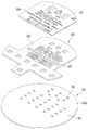
도 17은 본 발명의 실시예에 따른 토출그릴에 결합되는 디스플레이 장치의 구성을 보여주는 분해 사시도이고, 도 18은 본 발명의 실시예에 따른 토출그릴에 PCB 어셈블리가 결합되는 모습을 보여주는 도면이고, 도 19는 본 발명의 실시예에 따른 PCB 어셈블리의 구성을 보여주는 분해 사시도이고, 도 20은 본 발명의 실시예에 따른 디스플레이 장치의 상면 구성을 보여주는 도면이고, 도 21은 본 발명의 실시예에 따른 PCB 어셈블리의 저면 구성을 보여주는 도면이다.17 is an exploded perspective view illustrating a configuration of a display apparatus coupled to a discharge grill according to an embodiment of the present invention, and FIG. 18 is a view illustrating a PCB assembly coupled to a discharge grill according to an embodiment of the present invention. 19 is an exploded perspective view showing the configuration of a PCB assembly according to an embodiment of the present invention, Figure 20 is a view showing the top configuration of a display device according to an embodiment of the present invention, Figure 21 is a PCB according to an embodiment of the present invention Figure showing the bottom configuration of the assembly.
도 17 내지 도 21을 참조하면, 본 발명의 실시예에 따른 디스플레이 장치(600)는 상기 공기 청정기(10)의 상부에 설치될 수 있다. 상기 디스플레이 장치(600)의 디스플레이 화면(602)은 상기 공기 청정기(10)의 상면 중 적어도 일부를 구성할 수 있다.17 to 21, the
상기 디스플레이 장치(600)는 상기 토출그릴(315)에 설치될 수 있다. 상기 토출그릴(315)의 대략 중앙부에는 하방으로 함몰된 형상을 가지는 함몰부(318)가 구비되며, 상기 함몰부(318)로부터 반경방향 외측을 향하여 다수의 그릴부(315a)가 연장될 수 있다. 그리고, 상기 디스플레이 장치(600)는 상기 함몰부(318)의 상측에 배치될 수 있다.The
상기 디스플레이 장치(600)에는, PCB 어셈블리(601)가 포함된다. 상기 PCB 어셈블리(601)에는, 다수의 조명원(651,655)이 구비되는 디스플레이PCB(610) 및 상기 디스플레이PCB(610)의 상측에 결합되어 상기 다수의 조명원(651)으로부터 조사된 빛을 상기 디스플레이 화면(602)을 향하여 집중시켜 주는 리플렉터(620)가 포함된다.The
상기 다수의 조명원(651,655)에는, 공기 청정기(10)의 운전정보를 표시하기 위한 제 1 조명원(651) 및 상기 디스플레이 장치(600)의 디스플레이 화면(602)의 테두리를 표시하기 위한 제 2 조명원(655)이 포함된다. 상기 디스플레이 화면(602)은 상기 정보가 표시될 수 있는 설정된 영역(이하, 표시영역)으로서, 상기 디스플레이 장치(600)의 상면에 형성된다. 그리고, 상기 디스플레이 화면(602)의 테두리는 상기 표시영역의 경계를 형성할 수 있다.The plurality of
상기 디스플레이PCB(610)에는, 대략 원형의 기판본체(611)가 포함된다. 상기 기판본체(611)에는, 상기 제 1 조명원(651)이 설치되는 본체전면부(611a) 및 상기 제 2 조명원(655)이 설치되는 본체후면부(611b)가 포함된다.The
상기 제 1 조명원(651)은 디스플레이 되는 내용의 형상에 대응하여 상기 본체전면부(611a)에 다수 개가 구비될 수 있다. 그리고, 상기 제 2 조명원(655)은 다수 개가 구비되며, 상기 다수 개의 제 2 조명원(655)은 상기 본체후면부(611b)의 테두리를 따라 배치될 수 있다. 일례로, 상기 다수 개의 제 2 조명원(655)은 원형의 형상으로 배치될 수 있다.A plurality of
상기 리플렉터(620)에는, 리플렉터 본체(621) 및 상기 리플렉터 본체(621)에 형성되며, 상기 제 1 조명원(651)에서 조사되는 빛을 상방으로 집중시키는 관통홀(623)이 포함된다. 상기 리플렉터 본체(621)는 빛의 투과가 제한되는 불투명한 재질로 구성되거나, 상기 불투명한 재질이 코팅되도록 구성된다.The
상기 리플렉터(620)의 상측에는, 리플렉터 필름(625)이 구비된다. 상기 리플렉터 필름(625)에는, 디스플레이 되는 정보의 내용, 즉 소정의 문자, 숫자 또는 기호등이 표시되는 문양표시부(626)가 포함된다. 상기 리플렉터(620)를 통하여 집중된 빛은 상기 문양표시부(625)에 작용하여, 소정의 정보를 구현할 수 있다. 상기 문양표시부(626)는 투명한 재질로 구성될 수 있다.The
일례로, 도 19에 도시되는 바와 같이, 상기 문양표시부(626)에는, "냄새", "먼지", "미세먼지", "필터교체"와 같은 문자, 숫자를 표시할 수 있는 888 문양, 송풍량의 강도를 나타내는 기호등이 포함될 수 있다.For example, as illustrated in FIG. 19, the
상기 제 1 조명원(651)은 상기 문양표시부(626)와 대응되는 위치에 배치될 수 있다. 일례로, 상기 제 1 조명원(651)은 상기 문양표시부(626)의 하측에 배치될 수 있다. 상기 문양표시부(626)는 다수가 구비되어 다양한 문양을 구성하므로, 상기 제 1 조명원(651)은 상기 다수의 문양표시부(626)에 대응하여 다수 개가 구비될 수 있다. 상기 제 1 조명원(651)에서 조사되는 빛은 상기 문양표시부(626)를 투과하여 외부에 드러날 수 있다. 그리고, 상기 다수의 제 1 조명원(651)의 온/오프 제어에 의하여 다양한 정보가 표시될 수 있다.The
상기 디스플레이 장치(600)에는, 상기 PCB 어셈블리(601)의 외측을 둘러싸는 확산판(630)이 포함된다. 상기 확산판(630)은, 상기 제 2 조명원(655)에서 조사되는 빛을 확산하여 디스플레이 화면(622)의 테두리부(650)를 형성하는 구성으로서 이해될 수 있다.The
상기 확산판(630)은 상기 함몰부(318)의 테두리를 따라 배치될 수 있다. 상세히, 상기 확산판(630)에는, 상기 디스플레이PCB(610)를 둘러싸도록 배치되는 판 본체(631) 및 상기 판 본체(631)의 내주면으로부터 돌출되어 상기 제 2 조명원(655)이 설치되는 조명수용부(635)가 포함된다. 상기 판 본체(631)는 링 형상을 가질 수 있으며, 상기 토출그릴(315)에 지지될 수 있다. 그리고, 상기 판 본체(631) 및 조명수용부(635)는 일체로 이루어질 수 있다.The
상기 판 본체(631) 및 상기 조명수용부(635)는 빛의 굴절 또는 확산이 가능한 반투명 재질로 구성될 수 있다. 일례로, 상기 판 본체(631) 및 조명수용부(635)는 아크릴 재질로 구성될 수 있다.The
상기 판 본체(631)는 상기 디스플레이 화면(622)의 테두리부(650)를 구성할 수 있다. 상세히, 상기 판 본체(631)의 상부는 상기 공기 청정기(10)의 상면에 노출된 상태에 있을 수 있으며, 상기 제 2 조명원(655)에서 조사되는 빛은 상기 조명수용부(635) 및 판 본체(631)를 통하여 확산된다. 그리고, 상기 확산된 빛은 상기 공기 청정기(10)의 상부로 이동하여, 상기 테두리부(650)를 구성할 수 있다.The
상기 판 본체(631) 및 조명수용부(635)는 반투명 재질로 구성되므로, 상기 테두리부(650)는 은은한 빛으로 구현될 수 있다. 따라서, 편안한 느낌의 디스플레이 화면을 구성할 수 있다.Since the
상기 디스플레이 장치(600)에는, 상기 PCB어셈블리(601)의 상측에 구비되는 디스플레이 커버(600)가 더 포함된다. 상기 디스플레이 커버(640)는 상기 디스플레이PCB(610)의 외측을 지지하고 커버필름(645)를 편평하게 유지하기 위한 구성으로서 이해될 수 있다. 상기 디스플레이 커버(640)는 빛의 투과를 방지하는 불투명 재질로 구성될 수 있다.The
상기 디스플레이 커버(640)에는, 상기 리플렉터 필름(625)에 대응되는 형상을 가지는 커버홀(641)이 형성된다. 상기 커버홀(641)의 구성에 의하여, 상기 리플렉터(620)에 상기 디스플레이 커버(640)가 결합되더라도, 상기 리플렉터 필름(625)는 상방을 향하여 노출될 수 있다.A
상기 디스플레이 커버(640)의 상측에는, 커버필름(645)이 구비된다. 일례로, 상기 커버필름(645)은 상기 디스플레이 커버(640)의 상면에 부착될 수 있다. 상기 커버필름(645)은, 상기 PCB어셈블리(601)에서 전달되는 빛 중 일부만을 투과시키기 위하여 반투명 재질로 구성될 수 있다. 일례로, 상기 반투명 재질에는, 아크릴 또는 폴리메타크릴산 메틸수지(PMMA)가 포함될 수 있다. 상기 커버필름(645)이 구비됨으로써, 상기 디스플레이 장치(600)를 통하여 표시되는 정보가 너무 눈부시게 구현되는 것을 방지할 수 있다.The
상기 커버필름(645)에는, 사용자가 소정의 명령을 입력하거나 공기 청정기(10)의 다수의 운전정보 중 일부 운전정보를 디스플레이 하는 필름표시부(646)가 구비된다.The
도 22 내지 도 24는 본 발명의 실시예에 따른 공기 청정기에서의 공기유동 모습을 보여주는 도면이다.22 to 24 are views showing the state of air flow in the air purifier according to the embodiment of the present invention.
먼저, 제 1 송풍장치(100)의 구동에 따른 공기의 흐름을 설명한다. 제 1 팬(160)이 구동하면, 제 1 흡입부(102) 및 베이스흡입부(103)를 통하여 실내공기가 제 1 케이스(101)의 내부로 흡입된다. 흡입된 공기는 제 1 필터부재(120)를 통과하며, 이 과정에서 공기 중 이물이 필터링 될 수 있다. 그리고, 공기가 제 1 필터부재(120)를 통과하는 과정에서, 공기는 제 1 필터부재(120)의 반경방향으로 흡입하여 필터링 된 후, 상방으로 유동한다.First, the flow of air according to the driving of the
상기 제 1 필터부재(120)를 통과한 공기는 제 1 팬(160)을 통과하면서 반경방향 상측으로 유동하며, 제 1,2 에어가이드 장치(170,180)를 통과하면서 안정적인 상방 유동이 이루어진다. 상기 제 1,2 에어가이드 장치(170,180)를 통과한 공기는 제 1 토출가이드 장치(190)를 지나며, 제 1 토출부(105)를 통하여 상방으로 유동한다.Air passing through the
상기 제 1 토출부(105)를 통하여 배출된 공기는 상기 제 1 토출가이드 장치(190)의 상측에 위치한 구획판(430)에 의하여 가이드 되어 상기 공기 청정기(10)의 외부로 배출된다.The air discharged through the
한편, 제 2 팬(260)이 구동하면, 제 2 흡입부(202)를 통하여 실내공기가 제 2 케이스(201)의 내부로 흡입된다. 흡입된 공기는 제 2 필터부재(220)를 통과하며, 이 과정에서 공기 중 이물이 필터링 될 수 있다. 그리고, 공기가 제 2 필터부재(220)를 통과하는 과정에서, 공기는 제 1 필터부재(120)의 반경방향으로 흡입하여 필터링 된 후, 상방으로 유동한다.On the other hand, when the
상기 제 2 필터부재(220)를 통과한 공기는 제 2 팬(160)을 통과하면서 반경방향 상측으로 유동하며, 제 3 에어가이드 장치(270) 및 제 2 토출가이드 장치(280)를 통과하면서 안정적인 상방 유동이 이루어진다. 상기 제 3 에어가이드 장치(270) 및 제 2 토출가이드 장치(280)를 통과한 공기는 유동전환 장치(300)를 경유하여 제 2 토출부(305)를 통하여 배출될 수 있다.Air passing through the
상기 유동전환 장치(300)는 제 2 가이드 기구에 의하여 상하 방향으로 회전 가능하게 구비될 수 있다. 일례로, 도 22 내지 도 24에 도시되는 바와 같이, 상기 유동전환 장치(300)가 제 1 위치에 있으면, 상기 유동전환 장치(300)에서 배출된 공기는 상방으로 유동된다.The
반면에, 상기 유동전환 장치(300)가 제 2 위치에 있으면, 상기 유동전환 장치(300)에서 배출된 공기는 전방 상측을 향하여 유동될 수 있다. 상기 유동전환 장치(300)에 의하여, 공기 청정기(10)에서 배출되는 공기의 풍량은 증가되고, 공기 청정기(10)로부터 멀리 떨어진 위치까지 정화된 공기가 공급될 수 있다는 장점이 있다.On the other hand, when the
상세히, 상기 유동전환 장치(300)의 제 3 팬(330)이 구동하면, 상기 제 2 토출가이드 장치(280)에서 배출된 공기 중 적어도 일부의 공기가 상기 제 3 팬하우징(310)의 내부로 유입될 수 있다. 그리고, 상기 유입된 공기는 상기 제 3 팬(330)을 통과하고, 상기 제 2 토출부(305)를 통하여 외부로 배출될 수 있다.In detail, when the
한편, 상기 유동전환 장치(300)는 상기 제 2 위치에 있는 상태에서, 제 1 가이드 기구에 의하여 좌우 방향으로 회전될 수 있다. 일례로, 도 14 및 도 15에 도시되는 바와 같이, 상기 유동전환 장치(300)가 전방 상측을 향하는 경우, 상기 제 2 토출부(305)를 통하여 배출되는 공기는 전방 상측으로 유동될 수 있다. 반면에, 도 16에 도시되는 바와 같이, 상기 유동전환 장치(300)가 후방 상측을 향하는 경우, 상기 제 2 토출부(305)를 통하여 배출되는 공기는 후방 상측으로 유동될 수 있다.On the other hand, the
이러한 작용에 의하면, 공기 청정기(10)로부터 토출되는 공기가 단순히 상방을 향하는 것이 아니라, 전방을 향할 수 있으므로, 공기 청정기(10)로부터 상대적으로 멀리 떨어진 공간을 향하는 기류가 발생할 수 있다. 그리고, 상기 유동전환 장치(300)에는 별도의 제 3 팬(330)이 구비되므로, 토출되는 공기의 송풍력이 증가될 수 있다.According to this action, since the air discharged from the
또한, 상기 유동전환 장치(300)는 상기 제 1 방향 회전을 수행할 수 있으므로, 상기 공기 청정기(10)의 전방 양측으로 공기를 토출할 수 있고, 이에 따라 상대적으로 넓은 실내공간을 향하여 기류를 제공할 수 있다는 효과가 나타난다.In addition, since the
공기 청정기(10)의 운전모드에 따라, 상기 유동전환 장치(300)는 선택적으로 작용할 수 있다. 공기 청정기(10)가 일반운전 모드(제 1 운전모드)로 운전되는 경우, 도 22 및 도 23에 도시되는 바와 같이, 상기 유동전환 장치(300)는 누워져 있는 제 1 위치에 있게 된다. 그리고, 상기 제 1,2 송풍장치(100,200)가 구동하여, 독립된 다수의 기류가 형성될 수 있다.According to the operation mode of the
즉, 상기 제 1 송풍장치(100)가 구동하면, 상기 제 1 흡입부(102) 및 베이스흡입부(103)를 통한 공기의 흡입이 이루어지고, 제 1 필터부재(120) 및 제 1 팬(160)을 통과하여 상기 제 1 토출부(105)를 통하여 배출될 수 있다. 그리고, 상기 제 2 송풍장치(200)가 구동되면, 상기 제 2 흡입부(202)를 통한 공기의 흡입이 이루어지고, 제 2 필터부재(220) 및 제 2 팬(260)을 통과하며, 상기 제 3 팬(330)을 경유할 수 있다. 그리고, 상기 제 2 토출부(305)를 통하여 상방을 향하여 배출될 수 있다. 이 때, 상기 제 3 팬(330)은 오프될 수 있다. 물론, 상기 제 2 토출부(305)를 향한 토출기류를 강하게 형성하기 위하여, 상기 제 3 팬(330)이 구동될 수 있음은 물론이다.That is, when the
한편, 상기 유동전환 장치(300)는 제 1 위치에 있는 상태에서, 제 1 방향 회전을 하면서, 상기 공기 청정기(10)의 전방 양측 방향으로 기류를 변화시킬 수도 있을 것이다.On the other hand, while the
반면에, 상기 공기 청정기(10)가 유동전환 모드(제 2 운전모드)로 운전되는 경우, 도 24에 도시되는 바와 같이, 상기 유동전환 장치(300)는 상방으로 회전하여, 공기 청정기(10)의 상단부로부터 돌출될 수 있다. 한편, 유동전환 모드에서, 상기 제 1,2 송풍장치(100,200)의 구동은 일반운전 모드에서의 제 1,2 송풍장치(100,200)의 구동모습과 동일할 수 있다.On the other hand, when the
그리고, 상기 제 3 팬(330)은 구동되며, 이에 따라 상기 제 2 팬(260) 및 제 2 토출가이드 장치(280)의 토출유로(282a)을 통과한 공기 중, 적어도 일부의 공기는 상기 제 3 팬하우징(310)으로 유입된다. 그리고, 상기 유입된 공기 중 적어도 일부의 공기는 상기 제 3 팬(330)을 통과하면서, 상기 공기 청정기(10)의 전방 상측 또는 후방 상측을 향하여 토출될 수 있다.In addition, the
10 : 공기 청정기20 : 베이스
100 : 송풍장치100 : 제 1 송풍장치
101 : 제 1 케이스110 : 흡입그릴
120 : 제 1 필터부재130 : 제 1 필터프레임
140 : 지지장치142 : 레버장치
150 : 제 1 팬하우징160 : 제 1 팬
170 : 제 1 에어가이드 장치180 : 제 2 에어가이드 장치
190 : 제 1 토출가이드 장치200 : 제 2 송풍장치
201 : 제 2 케이스220 : 제 2 필터부재
230 : 제 2 필터프레임250 : 제 2 팬하우징
260 : 제 2 팬270 : 제 3 에어가이드 장치
280 : 제 2 토출가이드 장치300 : 유동전환 장치
310 : 제 3 팬하우징320 : 유동 가이드부
330 : 제 3 팬350 : 회전 가이드장치
400 : 구획장치430 : 구획판
600 : 디스플레이 장치610 : 디스플레이PCB
620 : 리플렉터630 : 반사판10: air cleaner 20: base
100: blower 100: first blower
101: first case 110: suction grill
120: first filter member 130: first filter frame
140: support device 142: lever device
150: first fan housing 160: first fan
170: first air guide device 180: second air guide device
190: first discharge guide device 200: second blower
201: second case 220: second filter member
230: second filter frame 250: second fan housing
260: second fan 270: third air guide device
280: second discharge guide device 300: flow switching device
310: third fan housing 320: flow guide portion
330: third fan 350: rotation guide device
400: partition device 430: partition plate
600: display device 610: display PCB
620: reflector 630: reflector
Claims (10)
Translated fromKorean공기의 유동을 발생시키는 송풍팬과, 상기 송풍팬이 수용되는 팬하우징과, 환형으로 형성되고 상기 팬하우징의 상측에 구비되는 토출가이드 장치를 포함하는 송풍장치; 및
상기 송풍장치의 상측에 구비되고, 상기 송풍장치에서 발생된 공기가 유입되는 유입그릴과, 유입 공기의 토출방향을 전환하도록 공기의 유동을 발생시키는 유동전환팬을 포함하는 유동 전환장치를 포함하되,
상기 토출가이드 장치는, 외주면을 형성하는 토출외벽, 상기 토출외벽의 반경 방향 내측에 위치하는 원통형의 토출내벽 및 상기 토출외벽과 토출내벽 사이에서 연장되는 토출그릴을 구비하되,
상기 토출그릴은 하방으로 오목한 형상으로 형성되고, 상기 유입그릴은 상기 토출그릴의 형상에 대응하여 하방으로 오목한 형상으로 형성되며,
상기 유입그릴이 상기 토출그릴에 안착되도록 위치하는 경우, 상기 토출가이드 장치를 통해 토출되는 공기가 상기 유입그릴로 인입되도록, 상기 토출외벽 및 토출그릴이 각각 상하방향으로 연장 형성되는 공기 청정기.In the air purifier,
A blower including a blower fan for generating a flow of air, a fan housing accommodating the blower fan, and a discharge guide device formed in an annular shape and provided above the fan housing; And
Is provided on the upper side of the blower, and includes a flow switching device including an inlet grill to which the air generated in the blower is introduced, and a flow conversion fan for generating a flow of air to change the discharge direction of the inlet air,
The discharge guide device includes a discharge outer wall forming an outer circumferential surface, a cylindrical discharge inner wall located radially inward of the discharge outer wall, and a discharge grill extending between the discharge outer wall and the discharge inner wall,
The discharge grill is formed in a concave shape downward, the inflow grill is formed in a concave downward shape corresponding to the shape of the discharge grill,
When the inlet grill is positioned to be seated on the discharge grill, the discharge outer wall and the discharge grill is extended in the vertical direction so that the air discharged through the discharge guide device is introduced into the inlet grill.
상기 토출가이드 장치는 환형으로 형성되고,
상기 토출가이드 장치의 토출외벽 및 토출내벽은 원통형으로 형성되는 공기 청정기.The method of claim 1,
The discharge guide device is formed in an annular shape,
And a discharge outer wall and a discharge inner wall of the discharge guide device have a cylindrical shape.
상기 유입그릴이 상기 토출그릴의 상면으로부터 상방으로 이격되는 경우, 상기 토출가이드 장치를 통해 토출되는 공기가 이격공간을 지나 상기 유입그릴로 인입되도록, 상기 유동 전환장치가 상기 토출외벽의 반경 방향 내측에 위치하는 공기 청정기.The method of claim 1,
When the inlet grill is spaced upwardly from the upper surface of the discharge grill, the flow switching device is radially inward of the discharge outer wall so that the air discharged through the discharge guide device is introduced into the inlet grill through the separation space. Located air purifier.
상기 송풍장치는,
상기 토출가이드 장치 하측에 결합되어, 상기 송풍팬을 통과한 공기의 유동을 상기 토출가이드 장치로 가이드하도록 구비되며, 외주면을 형성하는 원통형의 외벽, 상기 외벽의 반경 방향 내측에 위치하는 원통형의 내벽 및 상기 외벽과 내벽 사이에 형성되는 공기유로를 구비하는 에어가이드 장치를 포함하는 공기 청정기.The method of claim 1,
The blower is,
A cylindrical outer wall coupled to a lower side of the discharge guide device and configured to guide the flow of air passing through the blower fan to the discharge guide device, the cylindrical outer wall forming an outer circumferential surface, and a cylindrical inner wall located in a radially inner side of the outer wall; And an air guide device having an air flow path formed between the outer wall and the inner wall.
상기 외벽 및 토출외벽은 상하 방향으로 정렬되도록 구비되는 공기 청정기.The method of claim 4, wherein
The outer wall and the discharge outer wall is provided to be aligned in the vertical direction.
상기 유입그릴이 상기 토출그릴의 상면에 안착되도록 위치하는 경우, 상기 토출가이드 장치를 통해 토출되는 공기가 상기 유입그릴로 인입되도록, 상기 유입그릴이 상하방향으로 연장 형성되는 공기 청정기.The method of claim 1,
When the inlet grill is positioned so as to be seated on the upper surface of the discharge grill, the inlet grill extends in the vertical direction so that the air discharged through the discharge guide device is introduced into the inlet grill.
상기 유동 전환장치가 상기 송풍장치에 대해 좌우 방향으로 회전하도록 구비되고, 제1 기어모터에 의해 회전하는 제1 기어와, 상기 제1 기어와 연동하도록 형성되는 제1 랙을 포함하는 제1 가이드 기구를 포함하는 공기 청정기.The method of claim 1,
The first guide mechanism is provided so that the flow switching device is rotated in the horizontal direction with respect to the blower, the first gear rotates by a first gear motor, and a first rack formed to interlock with the first gear. Air purifier comprising a.
상기 유동 전환장치가 상기 송풍장치에 대해 상하 방향으로 회전하도록 구비되고, 제2 기어모터에 의해 회전하는 제2 기어와, 상기 제2 기어와 연동하도록 형성되는 제2 랙을 포함하는 제2 가이드 기구를 포함하는 공기 청정기.The method of claim 7, wherein
The second guide mechanism is provided so that the flow switching device is rotated in the up and down direction with respect to the blower, the second gear rotated by a second gear motor, and a second rack formed to interlock with the second gear. Air purifier comprising a.
상기 제2 가이드 기구에 의해,
상기 유동 전환장치가 하향 회전함에 따라 상기 유입그릴이 상기 토출그릴의 상면에 안착되고,
상기 유동 전환장치가 상향 회전함에 따라 상기 유입그릴이 상기 토출그릴의 상면으로부터 상방으로 이격되는 공기 청정기.The method of claim 8,
By the second guide mechanism,
As the flow switching device rotates downward, the inlet grill is seated on the upper surface of the discharge grill,
And the inlet grill is spaced upwardly from an upper surface of the discharge grill as the flow diverter rotates upward.
상기 제1 가이드 기구 및 제2 가이드 기구는 상기 토출내벽의 반경 방향 내측에 위치하는 공기 청정기.
The method of claim 9,
And the first guide mechanism and the second guide mechanism are located radially inward of the discharge inner wall.
Priority Applications (1)
| Application Number | Priority Date | Filing Date | Title |
|---|---|---|---|
| KR1020190134832AKR102188897B1 (en) | 2019-10-28 | 2019-10-28 | Air cleaning apparatus |
Applications Claiming Priority (1)
| Application Number | Priority Date | Filing Date | Title |
|---|---|---|---|
| KR1020190134832AKR102188897B1 (en) | 2019-10-28 | 2019-10-28 | Air cleaning apparatus |
Related Parent Applications (1)
| Application Number | Title | Priority Date | Filing Date |
|---|---|---|---|
| KR1020180045552ADivisionKR102127919B1 (en) | 2018-04-19 | 2018-04-19 | Air cleaning apparatus |
Publications (2)
| Publication Number | Publication Date |
|---|---|
| KR20190124684Atrue KR20190124684A (en) | 2019-11-05 |
| KR102188897B1 KR102188897B1 (en) | 2020-12-11 |
Family
ID=68577043
Family Applications (1)
| Application Number | Title | Priority Date | Filing Date |
|---|---|---|---|
| KR1020190134832AActiveKR102188897B1 (en) | 2019-10-28 | 2019-10-28 | Air cleaning apparatus |
Country Status (1)
| Country | Link |
|---|---|
| KR (1) | KR102188897B1 (en) |
Citations (2)
| Publication number | Priority date | Publication date | Assignee | Title |
|---|---|---|---|---|
| KR20160012796A (en)* | 2014-07-25 | 2016-02-03 | 엘지전자 주식회사 | Humidifier |
| KR20160017587A (en)* | 2014-08-04 | 2016-02-16 | 삼성전자주식회사 | Air conditioner |
- 2019
- 2019-10-28KRKR1020190134832Apatent/KR102188897B1/enactiveActive
Patent Citations (2)
| Publication number | Priority date | Publication date | Assignee | Title |
|---|---|---|---|---|
| KR20160012796A (en)* | 2014-07-25 | 2016-02-03 | 엘지전자 주식회사 | Humidifier |
| KR20160017587A (en)* | 2014-08-04 | 2016-02-16 | 삼성전자주식회사 | Air conditioner |
Also Published As
| Publication number | Publication date |
|---|---|
| KR102188897B1 (en) | 2020-12-11 |
Similar Documents
| Publication | Publication Date | Title |
|---|---|---|
| KR102026194B1 (en) | Air cleaning apparatus | |
| KR102503863B1 (en) | Air cleaning apparatus | |
| KR101809410B1 (en) | Air cleaning apparatus | |
| KR101809411B1 (en) | Air cleaning apparatus | |
| KR102067814B1 (en) | Air cleaning apparatus | |
| KR20190119564A (en) | Air cleaning apparatus | |
| KR20190120126A (en) | Air cleaning apparatus | |
| KR102024171B1 (en) | Air cleaning apparatus | |
| KR20180000285A (en) | Air cleaning apparatus | |
| KR102044163B1 (en) | Air cleaning apparatus | |
| KR102034683B1 (en) | Air cleaning apparatus | |
| KR102034676B1 (en) | Air cleaning apparatus | |
| KR102160152B1 (en) | Air cleaning apparatus | |
| KR102044175B1 (en) | Air cleaning apparatus | |
| KR102446867B1 (en) | Air cleaning apparatus | |
| KR102127919B1 (en) | Air cleaning apparatus | |
| KR102127936B1 (en) | Air cleaning apparatus | |
| KR102044167B1 (en) | Air cleaning apparatus | |
| KR102034695B1 (en) | Air cleaning apparatus | |
| KR102024175B1 (en) | Air cleaning apparatus | |
| KR102060745B1 (en) | Air cleaning apparatus | |
| KR102447440B1 (en) | air cleaner | |
| KR102445947B1 (en) | Air cleaning apparatus | |
| KR20190124684A (en) | Air cleaning apparatus | |
| KR102160149B1 (en) | Air cleaning apparatus |
Legal Events
| Date | Code | Title | Description |
|---|---|---|---|
| A107 | Divisional application of patent | ||
| PA0107 | Divisional application | Comment text:Divisional Application of Patent Patent event date:20191028 Patent event code:PA01071R01D Filing date:20180419 Application number text:1020180045552 | |
| PG1501 | Laying open of application | ||
| PA0201 | Request for examination | Patent event code:PA02012R01D Patent event date:20200519 Comment text:Request for Examination of Application Patent event code:PA02011R04I Patent event date:20191028 Comment text:Divisional Application of Patent | |
| E902 | Notification of reason for refusal | ||
| PE0902 | Notice of grounds for rejection | Comment text:Notification of reason for refusal Patent event date:20200618 Patent event code:PE09021S01D | |
| E701 | Decision to grant or registration of patent right | ||
| PE0701 | Decision of registration | Patent event code:PE07011S01D Comment text:Decision to Grant Registration Patent event date:20200907 | |
| GRNT | Written decision to grant | ||
| PR0701 | Registration of establishment | Comment text:Registration of Establishment Patent event date:20201203 Patent event code:PR07011E01D | |
| PR1002 | Payment of registration fee | Payment date:20201204 End annual number:3 Start annual number:1 | |
| PG1601 | Publication of registration |