KR20190121772A - Methods and systems for improving the positioning accuracy of high frequency ablation procedures through reference marking - Google Patents
Methods and systems for improving the positioning accuracy of high frequency ablation procedures through reference markingDownload PDFInfo
- Publication number
- KR20190121772A KR20190121772AKR1020197024613AKR20197024613AKR20190121772AKR 20190121772 AKR20190121772 AKR 20190121772AKR 1020197024613 AKR1020197024613 AKR 1020197024613AKR 20197024613 AKR20197024613 AKR 20197024613AKR 20190121772 AKR20190121772 AKR 20190121772A
- Authority
- KR
- South Korea
- Prior art keywords
- target nerve
- introducer
- fiducial marker
- probe
- nerve
- Prior art date
- Legal status (The legal status is an assumption and is not a legal conclusion. Google has not performed a legal analysis and makes no representation as to the accuracy of the status listed.)
- Withdrawn
Links
- 238000000034methodMethods0.000titleclaimsabstractdescription99
- 238000002679ablationMethods0.000titledescription7
- 210000005036nerveAnatomy0.000claimsabstractdescription241
- 239000000523sampleSubstances0.000claimsabstractdescription239
- 239000003550markerSubstances0.000claimsabstractdescription139
- 208000002193PainDiseases0.000claimsabstractdescription51
- 238000007674radiofrequency ablationMethods0.000claimsabstractdescription43
- 239000002831pharmacologic agentSubstances0.000claimsabstractdescription41
- 230000019491signal transductionEffects0.000claimsabstractdescription10
- 239000007788liquidSubstances0.000claimsdescription28
- 229920000642polymerPolymers0.000claimsdescription20
- 229910052751metalInorganic materials0.000claimsdescription13
- 239000002184metalSubstances0.000claimsdescription12
- 239000011343solid materialSubstances0.000claimsdescription12
- 238000003780insertionMethods0.000claimsdescription10
- 230000037431insertionEffects0.000claimsdescription10
- 238000002594fluoroscopyMethods0.000claimsdescription9
- 230000001052transient effectEffects0.000claimsdescription9
- 238000002604ultrasonographyMethods0.000claimsdescription9
- 238000002601radiographyMethods0.000claimsdescription8
- 238000012546transferMethods0.000claimsdescription7
- 210000000578peripheral nerveAnatomy0.000claimsdescription6
- 239000000615nonconductorSubstances0.000claimsdescription5
- 239000000919ceramicSubstances0.000claimsdescription4
- 210000000278spinal cordAnatomy0.000claimsdescription3
- BQCADISMDOOEFD-UHFFFAOYSA-NSilverChemical compound[Ag]BQCADISMDOOEFD-UHFFFAOYSA-N0.000claimsdescription2
- 238000004873anchoringMethods0.000claims2
- 241001226615Asphodelus albusSpecies0.000claims1
- 210000001519tissueAnatomy0.000description32
- 238000011282treatmentMethods0.000description32
- 230000003902lesionEffects0.000description30
- 238000001816coolingMethods0.000description21
- 239000000463materialSubstances0.000description15
- 230000001537neural effectEffects0.000description13
- 239000012809cooling fluidSubstances0.000description10
- 238000010292electrical insulationMethods0.000description7
- -1polyethylenePolymers0.000description7
- 238000009529body temperature measurementMethods0.000description6
- 239000011248coating agentSubstances0.000description6
- 238000000576coating methodMethods0.000description6
- 210000000988bone and boneAnatomy0.000description5
- 239000000017hydrogelSubstances0.000description5
- 239000011810insulating materialSubstances0.000description5
- 210000001032spinal nerveAnatomy0.000description5
- 230000000903blocking effectEffects0.000description4
- 239000012777electrically insulating materialSubstances0.000description4
- 230000007246mechanismEffects0.000description4
- 239000010935stainless steelSubstances0.000description4
- 229910001220stainless steelInorganic materials0.000description4
- 238000004891communicationMethods0.000description3
- 239000004020conductorSubstances0.000description3
- 239000003814drugSubstances0.000description3
- 239000012530fluidSubstances0.000description3
- 150000002739metalsChemical class0.000description3
- 229910001000nickel titaniumInorganic materials0.000description3
- 230000000638stimulationEffects0.000description3
- 206010000084Abdominal pain lowerDiseases0.000description2
- IJGRMHOSHXDMSA-UHFFFAOYSA-NAtomic nitrogenChemical compoundN#NIJGRMHOSHXDMSA-UHFFFAOYSA-N0.000description2
- 208000023890Complex Regional Pain SyndromesDiseases0.000description2
- 208000005890NeuromaDiseases0.000description2
- 208000000450Pelvic PainDiseases0.000description2
- 239000004743PolypropyleneSubstances0.000description2
- FAPWRFPIFSIZLT-UHFFFAOYSA-MSodium chlorideChemical compound[Na+].[Cl-]FAPWRFPIFSIZLT-UHFFFAOYSA-M0.000description2
- RTAQQCXQSZGOHL-UHFFFAOYSA-NTitaniumChemical compound[Ti]RTAQQCXQSZGOHL-UHFFFAOYSA-N0.000description2
- 229910045601alloyInorganic materials0.000description2
- 239000000956alloySubstances0.000description2
- 210000003484anatomyAnatomy0.000description2
- 238000013459approachMethods0.000description2
- 230000015572biosynthetic processEffects0.000description2
- 239000012267brineSubstances0.000description2
- 230000008859changeEffects0.000description2
- 230000003247decreasing effectEffects0.000description2
- 238000013461designMethods0.000description2
- 239000003193general anesthetic agentSubstances0.000description2
- 230000004807localizationEffects0.000description2
- 238000005259measurementMethods0.000description2
- 239000007769metal materialSubstances0.000description2
- 230000003794neural signal transductionEffects0.000description2
- HLXZNVUGXRDIFK-UHFFFAOYSA-Nnickel titaniumChemical compound[Ti].[Ti].[Ti].[Ti].[Ti].[Ti].[Ti].[Ti].[Ti].[Ti].[Ti].[Ni].[Ni].[Ni].[Ni].[Ni].[Ni].[Ni].[Ni].[Ni].[Ni].[Ni].[Ni].[Ni].[Ni]HLXZNVUGXRDIFK-UHFFFAOYSA-N0.000description2
- 239000002245particleSubstances0.000description2
- 239000004033plasticSubstances0.000description2
- 229920003023plasticPolymers0.000description2
- BASFCYQUMIYNBI-UHFFFAOYSA-NplatinumChemical compound[Pt]BASFCYQUMIYNBI-UHFFFAOYSA-N0.000description2
- 229920000139polyethylene terephthalatePolymers0.000description2
- 239000005020polyethylene terephthalateSubstances0.000description2
- 229920001155polypropylenePolymers0.000description2
- 229920001343polytetrafluoroethylenePolymers0.000description2
- 239000004810polytetrafluoroethyleneSubstances0.000description2
- 108090000765processed proteins & peptidesProteins0.000description2
- 230000004044responseEffects0.000description2
- 230000008054signal transmissionEffects0.000description2
- 239000011780sodium chlorideSubstances0.000description2
- HPALAKNZSZLMCH-UHFFFAOYSA-Msodium;chloride;hydrateChemical compoundO.[Na+].[Cl-]HPALAKNZSZLMCH-UHFFFAOYSA-M0.000description2
- 238000001356surgical procedureMethods0.000description2
- 229940124597therapeutic agentDrugs0.000description2
- 229910052719titaniumInorganic materials0.000description2
- 239000010936titaniumSubstances0.000description2
- 206010044652trigeminal neuralgiaDiseases0.000description2
- KIUKXJAPPMFGSW-DNGZLQJQSA-N(2S,3S,4S,5R,6R)-6-[(2S,3R,4R,5S,6R)-3-Acetamido-2-[(2S,3S,4R,5R,6R)-6-[(2R,3R,4R,5S,6R)-3-acetamido-2,5-dihydroxy-6-(hydroxymethyl)oxan-4-yl]oxy-2-carboxy-4,5-dihydroxyoxan-3-yl]oxy-5-hydroxy-6-(hydroxymethyl)oxan-4-yl]oxy-3,4,5-trihydroxyoxane-2-carboxylic acidChemical compoundCC(=O)N[C@H]1[C@H](O)O[C@H](CO)[C@@H](O)[C@@H]1O[C@H]1[C@H](O)[C@@H](O)[C@H](O[C@H]2[C@@H]([C@@H](O[C@H]3[C@@H]([C@@H](O)[C@H](O)[C@H](O3)C(O)=O)O)[C@H](O)[C@@H](CO)O2)NC(C)=O)[C@@H](C(O)=O)O1KIUKXJAPPMFGSW-DNGZLQJQSA-N0.000description1
- 208000006820ArthralgiaDiseases0.000description1
- 229920001661ChitosanPolymers0.000description1
- 102000008186CollagenHuman genes0.000description1
- 108010035532CollagenProteins0.000description1
- 102000009123FibrinHuman genes0.000description1
- 108010073385FibrinProteins0.000description1
- BWGVNKXGVNDBDI-UHFFFAOYSA-NFibrin monomerChemical compoundCNC(=O)CNC(=O)CNBWGVNKXGVNDBDI-UHFFFAOYSA-N0.000description1
- 229920002683GlycosaminoglycanPolymers0.000description1
- 230000005679Peltier effectEffects0.000description1
- 239000004698PolyethyleneSubstances0.000description1
- 239000002202Polyethylene glycolSubstances0.000description1
- HZEWFHLRYVTOIW-UHFFFAOYSA-N[Ti].[Ni]Chemical compound[Ti].[Ni]HZEWFHLRYVTOIW-UHFFFAOYSA-N0.000description1
- 239000002253acidSubstances0.000description1
- 239000000654additiveSubstances0.000description1
- 230000000996additive effectEffects0.000description1
- 229940035674anestheticsDrugs0.000description1
- 239000003242anti bacterial agentSubstances0.000description1
- 229940088710antibiotic agentDrugs0.000description1
- 230000037424autonomic functionEffects0.000description1
- 238000005452bendingMethods0.000description1
- 229910052790berylliumInorganic materials0.000description1
- ATBAMAFKBVZNFJ-UHFFFAOYSA-Nberyllium atomChemical compound[Be]ATBAMAFKBVZNFJ-UHFFFAOYSA-N0.000description1
- 230000002457bidirectional effectEffects0.000description1
- 229920002988biodegradable polymerPolymers0.000description1
- 239000004621biodegradable polymerSubstances0.000description1
- 239000012620biological materialSubstances0.000description1
- 229920001436collagenPolymers0.000description1
- 238000012790confirmationMethods0.000description1
- 239000002872contrast mediaSubstances0.000description1
- 239000002826coolantSubstances0.000description1
- 230000001419dependent effectEffects0.000description1
- 238000010586diagramMethods0.000description1
- 229940079593drugDrugs0.000description1
- 230000000694effectsEffects0.000description1
- 230000005611electricityEffects0.000description1
- 210000003414extremityAnatomy0.000description1
- 229950003499fibrinDrugs0.000description1
- 238000011010flushing procedureMethods0.000description1
- 230000006870functionEffects0.000description1
- 150000004676glycansChemical class0.000description1
- PCHJSUWPFVWCPO-UHFFFAOYSA-NgoldChemical compound[Au]PCHJSUWPFVWCPO-UHFFFAOYSA-N0.000description1
- 229910052737goldInorganic materials0.000description1
- 239000010931goldSubstances0.000description1
- 238000010438heat treatmentMethods0.000description1
- 229920002674hyaluronanPolymers0.000description1
- 229960003160hyaluronic acidDrugs0.000description1
- 229910052588hydroxylapatiteInorganic materials0.000description1
- 238000003384imaging methodMethods0.000description1
- 238000007654immersionMethods0.000description1
- 239000004615ingredientSubstances0.000description1
- 238000002347injectionMethods0.000description1
- 239000007924injectionSubstances0.000description1
- 238000009413insulationMethods0.000description1
- 239000012212insulatorSubstances0.000description1
- PNDPGZBMCMUPRI-UHFFFAOYSA-NiodineChemical compoundIIPNDPGZBMCMUPRI-UHFFFAOYSA-N0.000description1
- 230000007774longtermEffects0.000description1
- 238000002156mixingMethods0.000description1
- 239000000203mixtureSubstances0.000description1
- 238000012986modificationMethods0.000description1
- 230000004048modificationEffects0.000description1
- 230000005404monopoleEffects0.000description1
- 230000007659motor functionEffects0.000description1
- 230000005405multipoleEffects0.000description1
- 210000003205muscleAnatomy0.000description1
- 210000000944nerve tissueAnatomy0.000description1
- 229910052757nitrogenInorganic materials0.000description1
- 239000012811non-conductive materialSubstances0.000description1
- 230000003287optical effectEffects0.000description1
- 230000000149penetrating effectEffects0.000description1
- XYJRXVWERLGGKC-UHFFFAOYSA-Dpentacalcium;hydroxide;triphosphateChemical compound[OH-].[Ca+2].[Ca+2].[Ca+2].[Ca+2].[Ca+2].[O-]P([O-])([O-])=O.[O-]P([O-])([O-])=O.[O-]P([O-])([O-])=OXYJRXVWERLGGKC-UHFFFAOYSA-D0.000description1
- 208000033808peripheral neuropathyDiseases0.000description1
- 230000002085persistent effectEffects0.000description1
- 229910052697platinumInorganic materials0.000description1
- 229920000747poly(lactic acid)Polymers0.000description1
- 229920001610polycaprolactonePolymers0.000description1
- 229920000573polyethylenePolymers0.000description1
- 229920001223polyethylene glycolPolymers0.000description1
- 239000004626polylactic acidSubstances0.000description1
- 229920001282polysaccharidePolymers0.000description1
- 239000005017polysaccharideSubstances0.000description1
- 229920001296polysiloxanePolymers0.000description1
- 238000002360preparation methodMethods0.000description1
- 230000005855radiationEffects0.000description1
- 229910052705radiumInorganic materials0.000description1
- HCWPIIXVSYCSAN-UHFFFAOYSA-Nradium atomChemical compound[Ra]HCWPIIXVSYCSAN-UHFFFAOYSA-N0.000description1
- 238000011084recoveryMethods0.000description1
- 210000003131sacroiliac jointAnatomy0.000description1
- 239000004065semiconductorSubstances0.000description1
- 230000037152sensory functionEffects0.000description1
- 238000010008shearingMethods0.000description1
- 229910052709silverInorganic materials0.000description1
- 239000004332silverSubstances0.000description1
- 210000003625skullAnatomy0.000description1
- 229910000679solderInorganic materials0.000description1
- 230000003238somatosensory effectEffects0.000description1
- 238000005507sprayingMethods0.000description1
- 239000000126substanceSubstances0.000description1
- 208000011580syndromic diseaseDiseases0.000description1
- 230000001225therapeutic effectEffects0.000description1
- 210000000115thoracic cavityAnatomy0.000description1
- 238000012549trainingMethods0.000description1
- 210000003901trigeminal nerveAnatomy0.000description1
- 150000003673urethanesChemical class0.000description1
- 210000002700urineAnatomy0.000description1
- XLYOFNOQVPJJNP-UHFFFAOYSA-NwaterSubstancesOXLYOFNOQVPJJNP-UHFFFAOYSA-N0.000description1
Images


Classifications
- A—HUMAN NECESSITIES
- A61—MEDICAL OR VETERINARY SCIENCE; HYGIENE
- A61B—DIAGNOSIS; SURGERY; IDENTIFICATION
- A61B90/00—Instruments, implements or accessories specially adapted for surgery or diagnosis and not covered by any of the groups A61B1/00 - A61B50/00, e.g. for luxation treatment or for protecting wound edges
- A61B90/39—Markers, e.g. radio-opaque or breast lesions markers
- A—HUMAN NECESSITIES
- A61—MEDICAL OR VETERINARY SCIENCE; HYGIENE
- A61B—DIAGNOSIS; SURGERY; IDENTIFICATION
- A61B18/00—Surgical instruments, devices or methods for transferring non-mechanical forms of energy to or from the body
- A61B18/04—Surgical instruments, devices or methods for transferring non-mechanical forms of energy to or from the body by heating
- A61B18/12—Surgical instruments, devices or methods for transferring non-mechanical forms of energy to or from the body by heating by passing a current through the tissue to be heated, e.g. high-frequency current
- A61B18/14—Probes or electrodes therefor
- A61B18/148—Probes or electrodes therefor having a short, rigid shaft for accessing the inner body transcutaneously, e.g. for neurosurgery or arthroscopy
- A—HUMAN NECESSITIES
- A61—MEDICAL OR VETERINARY SCIENCE; HYGIENE
- A61K—PREPARATIONS FOR MEDICAL, DENTAL OR TOILETRY PURPOSES
- A61K31/00—Medicinal preparations containing organic active ingredients
- A—HUMAN NECESSITIES
- A61—MEDICAL OR VETERINARY SCIENCE; HYGIENE
- A61K—PREPARATIONS FOR MEDICAL, DENTAL OR TOILETRY PURPOSES
- A61K9/00—Medicinal preparations characterised by special physical form
- A61K9/0012—Galenical forms characterised by the site of application
- A61K9/0085—Brain, e.g. brain implants; Spinal cord
- A—HUMAN NECESSITIES
- A61—MEDICAL OR VETERINARY SCIENCE; HYGIENE
- A61P—SPECIFIC THERAPEUTIC ACTIVITY OF CHEMICAL COMPOUNDS OR MEDICINAL PREPARATIONS
- A61P25/00—Drugs for disorders of the nervous system
- A61P25/04—Centrally acting analgesics, e.g. opioids
- A—HUMAN NECESSITIES
- A61—MEDICAL OR VETERINARY SCIENCE; HYGIENE
- A61B—DIAGNOSIS; SURGERY; IDENTIFICATION
- A61B17/00—Surgical instruments, devices or methods
- A61B2017/00004—(bio)absorbable, (bio)resorbable or resorptive
- A—HUMAN NECESSITIES
- A61—MEDICAL OR VETERINARY SCIENCE; HYGIENE
- A61B—DIAGNOSIS; SURGERY; IDENTIFICATION
- A61B18/00—Surgical instruments, devices or methods for transferring non-mechanical forms of energy to or from the body
- A61B2018/00005—Cooling or heating of the probe or tissue immediately surrounding the probe
- A61B2018/00011—Cooling or heating of the probe or tissue immediately surrounding the probe with fluids
- A61B2018/00023—Cooling or heating of the probe or tissue immediately surrounding the probe with fluids closed, i.e. without wound contact by the fluid
- A—HUMAN NECESSITIES
- A61—MEDICAL OR VETERINARY SCIENCE; HYGIENE
- A61B—DIAGNOSIS; SURGERY; IDENTIFICATION
- A61B18/00—Surgical instruments, devices or methods for transferring non-mechanical forms of energy to or from the body
- A61B2018/00053—Mechanical features of the instrument of device
- A61B2018/00059—Material properties
- A61B2018/00071—Electrical conductivity
- A61B2018/00083—Electrical conductivity low, i.e. electrically insulating
- A—HUMAN NECESSITIES
- A61—MEDICAL OR VETERINARY SCIENCE; HYGIENE
- A61B—DIAGNOSIS; SURGERY; IDENTIFICATION
- A61B18/00—Surgical instruments, devices or methods for transferring non-mechanical forms of energy to or from the body
- A61B2018/00053—Mechanical features of the instrument of device
- A61B2018/00107—Coatings on the energy applicator
- A61B2018/00154—Coatings on the energy applicator containing and delivering drugs
- A—HUMAN NECESSITIES
- A61—MEDICAL OR VETERINARY SCIENCE; HYGIENE
- A61B—DIAGNOSIS; SURGERY; IDENTIFICATION
- A61B18/00—Surgical instruments, devices or methods for transferring non-mechanical forms of energy to or from the body
- A61B2018/00315—Surgical instruments, devices or methods for transferring non-mechanical forms of energy to or from the body for treatment of particular body parts
- A61B2018/00434—Neural system
- A—HUMAN NECESSITIES
- A61—MEDICAL OR VETERINARY SCIENCE; HYGIENE
- A61B—DIAGNOSIS; SURGERY; IDENTIFICATION
- A61B18/00—Surgical instruments, devices or methods for transferring non-mechanical forms of energy to or from the body
- A61B2018/00571—Surgical instruments, devices or methods for transferring non-mechanical forms of energy to or from the body for achieving a particular surgical effect
- A61B2018/00577—Ablation
- A—HUMAN NECESSITIES
- A61—MEDICAL OR VETERINARY SCIENCE; HYGIENE
- A61B—DIAGNOSIS; SURGERY; IDENTIFICATION
- A61B18/00—Surgical instruments, devices or methods for transferring non-mechanical forms of energy to or from the body
- A61B2018/00636—Sensing and controlling the application of energy
- A61B2018/00642—Sensing and controlling the application of energy with feedback, i.e. closed loop control
- A—HUMAN NECESSITIES
- A61—MEDICAL OR VETERINARY SCIENCE; HYGIENE
- A61B—DIAGNOSIS; SURGERY; IDENTIFICATION
- A61B18/00—Surgical instruments, devices or methods for transferring non-mechanical forms of energy to or from the body
- A61B2018/00636—Sensing and controlling the application of energy
- A61B2018/00696—Controlled or regulated parameters
- A61B2018/0072—Current
- A—HUMAN NECESSITIES
- A61—MEDICAL OR VETERINARY SCIENCE; HYGIENE
- A61B—DIAGNOSIS; SURGERY; IDENTIFICATION
- A61B18/00—Surgical instruments, devices or methods for transferring non-mechanical forms of energy to or from the body
- A61B2018/00636—Sensing and controlling the application of energy
- A61B2018/00696—Controlled or regulated parameters
- A61B2018/00744—Fluid flow
- A—HUMAN NECESSITIES
- A61—MEDICAL OR VETERINARY SCIENCE; HYGIENE
- A61B—DIAGNOSIS; SURGERY; IDENTIFICATION
- A61B18/00—Surgical instruments, devices or methods for transferring non-mechanical forms of energy to or from the body
- A61B2018/00636—Sensing and controlling the application of energy
- A61B2018/00773—Sensed parameters
- A61B2018/00791—Temperature
- A—HUMAN NECESSITIES
- A61—MEDICAL OR VETERINARY SCIENCE; HYGIENE
- A61B—DIAGNOSIS; SURGERY; IDENTIFICATION
- A61B18/00—Surgical instruments, devices or methods for transferring non-mechanical forms of energy to or from the body
- A61B2018/00636—Sensing and controlling the application of energy
- A61B2018/00904—Automatic detection of target tissue
- A—HUMAN NECESSITIES
- A61—MEDICAL OR VETERINARY SCIENCE; HYGIENE
- A61B—DIAGNOSIS; SURGERY; IDENTIFICATION
- A61B90/00—Instruments, implements or accessories specially adapted for surgery or diagnosis and not covered by any of the groups A61B1/00 - A61B50/00, e.g. for luxation treatment or for protecting wound edges
- A61B90/39—Markers, e.g. radio-opaque or breast lesions markers
- A61B2090/3925—Markers, e.g. radio-opaque or breast lesions markers ultrasonic
- A—HUMAN NECESSITIES
- A61—MEDICAL OR VETERINARY SCIENCE; HYGIENE
- A61B—DIAGNOSIS; SURGERY; IDENTIFICATION
- A61B90/00—Instruments, implements or accessories specially adapted for surgery or diagnosis and not covered by any of the groups A61B1/00 - A61B50/00, e.g. for luxation treatment or for protecting wound edges
- A61B90/39—Markers, e.g. radio-opaque or breast lesions markers
- A61B2090/3933—Liquid markers
- A—HUMAN NECESSITIES
- A61—MEDICAL OR VETERINARY SCIENCE; HYGIENE
- A61B—DIAGNOSIS; SURGERY; IDENTIFICATION
- A61B90/00—Instruments, implements or accessories specially adapted for surgery or diagnosis and not covered by any of the groups A61B1/00 - A61B50/00, e.g. for luxation treatment or for protecting wound edges
- A61B90/39—Markers, e.g. radio-opaque or breast lesions markers
- A61B2090/3937—Visible markers
- A61B2090/3941—Photoluminescent markers
- A—HUMAN NECESSITIES
- A61—MEDICAL OR VETERINARY SCIENCE; HYGIENE
- A61B—DIAGNOSIS; SURGERY; IDENTIFICATION
- A61B90/00—Instruments, implements or accessories specially adapted for surgery or diagnosis and not covered by any of the groups A61B1/00 - A61B50/00, e.g. for luxation treatment or for protecting wound edges
- A61B90/39—Markers, e.g. radio-opaque or breast lesions markers
- A61B2090/3966—Radiopaque markers visible in an X-ray image
- A—HUMAN NECESSITIES
- A61—MEDICAL OR VETERINARY SCIENCE; HYGIENE
- A61B—DIAGNOSIS; SURGERY; IDENTIFICATION
- A61B90/00—Instruments, implements or accessories specially adapted for surgery or diagnosis and not covered by any of the groups A61B1/00 - A61B50/00, e.g. for luxation treatment or for protecting wound edges
- A61B90/39—Markers, e.g. radio-opaque or breast lesions markers
- A61B2090/3987—Applicators for implanting markers
- A—HUMAN NECESSITIES
- A61—MEDICAL OR VETERINARY SCIENCE; HYGIENE
- A61B—DIAGNOSIS; SURGERY; IDENTIFICATION
- A61B90/00—Instruments, implements or accessories specially adapted for surgery or diagnosis and not covered by any of the groups A61B1/00 - A61B50/00, e.g. for luxation treatment or for protecting wound edges
- A61B90/39—Markers, e.g. radio-opaque or breast lesions markers
- A61B2090/3991—Markers, e.g. radio-opaque or breast lesions markers having specific anchoring means to fixate the marker to the tissue, e.g. hooks
Landscapes
- Health & Medical Sciences (AREA)
- Life Sciences & Earth Sciences (AREA)
- Surgery (AREA)
- Engineering & Computer Science (AREA)
- Veterinary Medicine (AREA)
- Public Health (AREA)
- Animal Behavior & Ethology (AREA)
- General Health & Medical Sciences (AREA)
- Biomedical Technology (AREA)
- Nuclear Medicine, Radiotherapy & Molecular Imaging (AREA)
- Heart & Thoracic Surgery (AREA)
- Medical Informatics (AREA)
- Molecular Biology (AREA)
- Neurosurgery (AREA)
- Neurology (AREA)
- Chemical & Material Sciences (AREA)
- Pharmacology & Pharmacy (AREA)
- Medicinal Chemistry (AREA)
- Plasma & Fusion (AREA)
- Physics & Mathematics (AREA)
- Otolaryngology (AREA)
- Oral & Maxillofacial Surgery (AREA)
- Pathology (AREA)
- Epidemiology (AREA)
- Bioinformatics & Cheminformatics (AREA)
- Chemical Kinetics & Catalysis (AREA)
- General Chemical & Material Sciences (AREA)
- Organic Chemistry (AREA)
- Pain & Pain Management (AREA)
- Psychology (AREA)
- Orthopedic Medicine & Surgery (AREA)
- Surgical Instruments (AREA)
- Combination Of More Than One Step In Electrophotography (AREA)
- Apparatus For Radiation Diagnosis (AREA)
Abstract
Translated fromKoreanDescription
Translated fromKorean본 발명은 일반적으로 신경 차단 또는 고주파 절제를 통해 통증을 치료하기 위한 시스템 및 방법에 관한 것이다.The present invention generally relates to systems and methods for treating pain via nerve block or radiofrequency ablation.
통증의 치료에서, 약리학적 작용제 및 고주파(RF) 절제를 통한 신경 차단은 종종 수일 또는 심지어 수개월의 시간 기간에 걸쳐 계획된 일련의 절차로서 수행된다. 예를 들어, 약리학적 작용제를 통해 목표 신경을 신경 차단하는 것은 통상적으로 목표 신경이 RF 절제에 의한 신경절제의 후보인지를 결정하기 위해 사용된다. 약리학적 작용제를 통한 신경 차단이 환자에게 일시적 통증 완화를 제공하는 경우, 목표 신경이 환자의 통증의 적어도 하나의 원인인 것으로 가정되고, 환자에게 장기적 완화를 제공하기 위해 추가 절차가 동일한 목표 신경의 RF 절제를 위해 계획된다. 초기 RF 절제 절차가 성공적일 때, 종종 RF 절제의 효과가 목표 신경의 재성장으로 인해 약화될 수 있기 때문에 환자는 종종 수개월 후 1회 이상의 추가적 RF 절제 절차를 위해 돌아온다.In the treatment of pain, nerve block via pharmacological agents and radiofrequency ablation (RF) ablation are often performed as a series of procedures planned over a period of days or even months. For example, nerve blocking of a target nerve via a pharmacological agent is typically used to determine if the target nerve is a candidate for neurotomy by RF ablation. If nerve blockade through a pharmacological agent provides temporary pain relief for a patient, it is assumed that the target nerve is at least one cause of the patient's pain, and that additional procedures may be applied to the RF of the same target nerve to provide long-term relief to the patient. Is planned for temperance. When the initial RF ablation procedure is successful, patients often return for one or more additional RF ablation procedures several months later because the effects of RF ablation may be weakened due to regrowth of the target nerve.
신경 차단 및 RF 절제 절차의 각각 동안의 목표는 약리학적 작용제 또는 RF 에너지를 목표 신경의 정확하게 동일한 거시적 부위로 전달하는 것이다. 목표 신경 옆에 바늘 팁 또는 프로브 팁을 적절하게 배치하는 것은 이들 절차가 성공하는데 필수적이다. 그러나, 실제로는, 목표 신경이 현재 이용가능한 임상적 방법을 사용하여서는 직접적으로 시각화될 수 없기 때문에, 하나의 절차로부터 다음 절차로 바늘 및 프로브 배치를 정확하게 복제하는 것은 어렵다. 따라서, 의사는 목표 신경의 실제 3차원 해부학적 위치의 교육된 추정을 행하기 위해 뼈 랜드마크의 이미지에 의존해야 한다. 형광투시법 및 초음파와 같은 다양한 양태가 바늘 및 프로브 배치 동안 뼈 랜드마크를 시각화하기 위해 사용될 수 있지만, 정확한 바늘 및 프로브 배치는 숙련된 손 및 수년의 훈련을 요구하는 어려운 기술이다.The goal during each of the nerve block and RF ablation procedures is to deliver the pharmacological agent or RF energy to exactly the same macroscopic site of the target nerve. Proper placement of the needle tip or probe tip next to the target nerve is essential for the success of these procedures. In practice, however, it is difficult to accurately replicate needle and probe placement from one procedure to the next because the target nerve cannot be directly visualized using currently available clinical methods. Thus, the physician must rely on the image of the bone landmark to make an educated estimation of the actual three-dimensional anatomical position of the target nerve. While various aspects, such as fluoroscopy and ultrasound, can be used to visualize bone landmarks during needle and probe placement, accurate needle and probe placement is a difficult technique that requires skilled hands and years of training.
따라서, 약리학적 작용제에 의한 신경 차단을 통해 이전에 식별된 목표 신경에 대해 RF 절제를 수행하기 위한 의료 전문가의 노력에도 불구하고, 초기 진단 신경 차단 절차 동안 통증 완화를 경험한 일부 환자는 후속 RF 절제 절차로부터 동일한 통증 완화를 경험하지 않는다. 마찬가지로, 목표 신경의 회복 또는 재성장에 의해 요구되는 추가의 RF 절제 절차는 제1 RF 절제 절차와 동일한 통증 완화를 제공하는데 종종 실패한다. 이러한 RF 절제 절차가 통증 완화를 제공하는데 실패하는 한가지 이유는, 바늘 또는 프로브가 이전에 통증 완화를 제공한 동일한 해부학적 위치에 배치되지 않기 때문이다.Thus, despite the medical practitioner's efforts to perform RF ablation on previously identified target nerves through nerve blockade by pharmacological agents, some patients who have experienced pain relief during the initial diagnostic neural block procedure are subject to subsequent RF ablation. Do not experience the same pain relief from the procedure. Likewise, additional RF ablation procedures required by recovery or regrowth of the target nerve often fail to provide the same pain relief as the first RF ablation procedure. One reason why this RF ablation procedure fails to provide pain relief is that the needle or probe is not placed in the same anatomical location that previously provided pain relief.
그러므로, 환자에게 일시적 통증 완화를 제공하는데 성공한 초기 진단 신경 차단 동안 및 환자에게 통증 완화를 제공하는데 성공한 이전 RF 절제 절차에서의 바늘 팁과 동일한 위치에 RF 절제 프로브의 팁을 정확하게 배치할 수 있는 통증을 치료하는 시스템 및 방법에 대한 필요성이 존재한다. 이전의 통증 완화를 촉진한 정확한 바늘 또는 프로브 위치가 알려져 있는 경우, 의료 전문가는 임의의 미래의 RF 절제 절차의 성공을 보장하기 위해 이전의 치료가 효과적인 것으로 입증된 정확한 위치에 에너지를 전달할 수 있다.Therefore, during the initial diagnostic neural blockade that has been successful in providing temporary pain relief to the patient, and in the same position as the needle tip in the previous RF ablation procedure that has been successful in providing pain relief to the patient, the pain can be accurately positioned. There is a need for systems and methods of treatment. If the exact needle or probe location that facilitated previous pain relief is known, the medical professional can deliver energy to the exact location where the previous treatment has proven effective to ensure the success of any future RF ablation procedure.
본 발명의 일 실시예에 따르면, 환자에 대해 수행된 고주파 절제 절차의 위치파악 정확도를 향상시키는 방법이 고려된다. 상기 방법은, a) 절제될 목표 신경을 식별하는 단계로서, 목표 신경은 통증의 원인인 것으로 의심되는, 목표 신경을 식별하는 단계; b) 목표 신경을 따르는 신경 신호 전달을 일시적으로 차단하기 위해 목표 신경에 약리학적 작용제를 전달하는 단계; c) 일시적 신경 차단이 환자가 경험하는 통증의 수준을 감소시키는 경우에 목표 신경이 통증의 원인이라고 확증하는 단계; d) 일시적 신경 차단이 환자가 경험하는 통증의 수준을 감소시킨다고 확증된 경우 목표 신경에 인접하게 기준 마커를 배치하는 단계; e) 기준 마커를 위치파악하는 단계; 및 f) 프로브를 통해 기준 마커에 인접하는 조직의 영역으로 고주파 에너지를 전달하는 단계로서, 상기 조직의 영역은 목표 신경에 대응하며 고주파 에너지는 목표 신경을 절제하기에 충분한 수준으로 인가되는, 고주파 에너지를 전달하는 단계를 포함한다.According to one embodiment of the present invention, a method is contemplated to improve the localization accuracy of a radiofrequency ablation procedure performed on a patient. The method includes the steps of: a) identifying a target nerve to be resected, wherein the target nerve is suspected of causing pain; b) delivering a pharmacological agent to the target nerve to temporarily block nerve signal transduction along the target nerve; c) confirming that the target nerve is the cause of the pain if the transient nerve block reduces the level of pain experienced by the patient; d) placing a reference marker adjacent to the target nerve if the temporary nerve block is confirmed to reduce the level of pain experienced by the patient; e) locating a reference marker; And f) delivering high frequency energy through a probe to a region of tissue adjacent to the fiducial marker, wherein the region of tissue corresponds to a target nerve and the high frequency energy is applied at a level sufficient to ablate the target nerve. It includes the step of delivering.
일 특정 실시예에서, 기준 마커는 초음파검사, 방사선촬영, 형광투시법, 또는 이들의 조합을 통해 위치파악될 수 있다.In one particular embodiment, the fiducial marker can be located via ultrasonography, radiography, fluoroscopy, or a combination thereof.
다른 실시예에서, 목표 신경은 척수 신경일 수 있다.In another embodiment, the target nerve may be a spinal nerve.
다른 실시예에서, 목표 신경은 말초 신경일 수 있다.In other embodiments, the target nerve may be a peripheral nerve.
또 다른 실시예에서, 방법은 단계 e) 및 f)를 반복하는 단계를 포함할 수 있다.In yet another embodiment, the method may comprise repeating steps e) and f).
또 다른 실시예에서, 기준 마커는 음향불투과성, 방사선불투과성 또는 형광성일 수 있다.In another embodiment, the fiducial marker can be acoustically impermeable, radiopaque or fluorescent.
하나의 추가의 실시예에서, 약리학적 작용제는 근위 단부 및 원위 단부를 갖는 도입기를 통해 목표 신경에 전달될 수 있으며, 이때 도입기의 원위 단부는 목표 신경에 인접한다.In one further embodiment, the pharmacological agent may be delivered to the target nerve through an introducer having a proximal end and a distal end, wherein the distal end of the introducer is adjacent to the target nerve.
하나의 특정 실시예에서, 기준 마커는 신체 내부로의 전개를 위해 도입기의 외면 상에 배치될 수 있다.In one particular embodiment, the fiducial marker can be placed on the outer surface of the introducer for deployment into the body.
다른 실시예에서, 기준 마커는 도입기를 통해 기준 마커를 전달함으로써 목표 신경에 인접하게 배치될 수 있고, 이때 도입기의 원위 단부는 목표 신경에 인접한다. 예를 들어, 일 실시예에서, 기준 마커는 전개 바늘 내에 저장될 수 있고, 여기서 전개 바늘은 전개 바늘의 개방 단부가 도입기의 원위 단부에 그리고 목표 신경에 인접하게 위치설정되도록 도입기의 근위 단부로부터 도입기 내로 삽입되며, 여기서 전개 바늘은 로드를 포함하고, 로드는 전개 바늘의 개방 단부로부터 기준 마커를 전개하도록 조작된다.In another embodiment, the fiducial marker can be placed adjacent to the target nerve by delivering the fiducial marker through the introducer, wherein the distal end of the introducer is adjacent to the target nerve. For example, in one embodiment, the fiducial marker can be stored in the deploying needle, where the deploying needle is positioned from the proximal end of the introducer such that the open end of the deploying needle is positioned at the distal end of the introducer and adjacent to the target nerve. Inserted into, wherein the deploying needle includes a rod, the rod being manipulated to deploy the fiducial marker from the open end of the deploying needle.
또 다른 실시예에서, 기준 마커는 고체 재료로부터 형성될 수 있다.In yet another embodiment, the fiducial marker can be formed from a solid material.
또 다른 실시예에서, 기준 마커는 하나 이상의 부속물을 포함할 수 있고, 여기서 부속물은 마커를 목표 신경에 또는 목표 신경에 인접한 조직에 고정시킨다.In another embodiment, the fiducial marker may comprise one or more appendages, where the appendages anchor the marker to the target nerve or to tissue adjacent to the target nerve.
하나의 추가의 실시예에서, 기준 마커는 액체 폴리머로서 목표 신경에 인접하게 주입될 수 있고, 여기서 액체 폴리머는 목표 신경에 인접하게 배치된 후에 경화된다. 또한, 액체 폴리머는 주사기를 통해 목표 신경으로 전달될 수 있고, 여기서 주사기는 도입기에 부착된다.In one further embodiment, the fiducial marker can be injected adjacent to the target nerve as a liquid polymer, where the liquid polymer is cured after being placed adjacent to the target nerve. In addition, the liquid polymer may be delivered to the target nerve via a syringe, where the syringe is attached to the introducer.
하나의 특정 실시예에서, 기준 마커는 비-분해성일 수 있다. 예를 들어, 기준 마커는 금속일 수 있다.In one particular embodiment, the fiducial marker may be non-degradable. For example, the fiducial marker may be a metal.
다른 실시예에서, 기준 마커는 고주파 절제 절차가 완료된 후에 제거될 수 있다.In another embodiment, the fiducial marker may be removed after the high frequency ablation procedure is completed.
또 다른 실시예에서, 기준 마커는 분해성일 수 있다.In another embodiment, the fiducial marker may be degradable.
본 발명의 다른 실시예에 따르면, 환자의 목표 신경에 대해 수행되는 고주파 절제 절차의 위치파악 정확도를 향상시키기 위한 시스템이 고려된다. 시스템은 외경, 근위 단부 및 원위 단부를 갖는 프로브로서, 프로브는 근위 단부에 위치된 전기 절연부 및 원위 단부에 위치된 목표 신경에 에너지를 전달하기 위한 도전부를 포함하는, 프로브; 목표 신경에 인접한 환자 내로 프로브의 원위 단부의 삽입을 용이하게 하기 위한 도입기로서, 도입기는 내경, 근위 단부, 및 원위 단부를 갖고, 프로브의 노출 도전부는 목표 신경으로의 에너지 전달 동안 원위 단부를 지나 연장되고, 프로브의 외경 및 도입기의 내경은 루멘을 형성하는, 도입기; 목표 신경을 따르는 신경 신호 전달을 차단하는데 충분한 양으로 공급되는 약리학적 작용제; 및 목표 신경에 인접하게 배치되도록 구성되는 기준 마커를 포함한다.According to another embodiment of the present invention, a system for improving the localization accuracy of a radiofrequency ablation procedure performed on a target nerve of a patient is contemplated. The system includes a probe having an outer diameter, a proximal end, and a distal end, the probe including an electrical insulator located at the proximal end and a conductive portion for delivering energy to a target nerve located at the distal end; An introducer for facilitating insertion of the distal end of the probe into a patient adjacent to the target nerve, the introducer having an inner diameter, proximal end, and distal end, wherein the exposed conductive portion of the probe extends past the distal end during energy transfer to the target nerve. Wherein the outer diameter of the probe and the inner diameter of the introducer form an introducer to form a lumen; Pharmacological agents supplied in an amount sufficient to block nerve signal transduction along the target nerve; And a fiducial marker configured to be positioned adjacent to the target nerve.
하나의 특정 실시예에서, 시스템은 환자에게 도입기를 삽입하는 것을 용이하게 하기 위한 폐색기를 또한 포함할 수 있다.In one particular embodiment, the system may also include an occluder to facilitate insertion of the introducer into the patient.
다른 실시예에서, 목표 신경은 척수 신경일 수 있다.In another embodiment, the target nerve may be a spinal nerve.
다른 실시예에서, 목표 신경은 말초 신경일 수 있다.In other embodiments, the target nerve may be a peripheral nerve.
또 다른 실시예에서, 기준 마커는 음향불투과성, 방사선불투과성, 또는 형광성일 수 있다.In another embodiment, the fiducial marker can be acoustically impermeable, radiopaque, or fluorescent.
또 다른 실시예에서, 도입기는 목표 신경에 약리학적 작용제를 전달할 수 있다.In another embodiment, the introducer can deliver a pharmacological agent to the target nerve.
하나의 추가의 실시예에서, 기준 마커는 신체 내부에의 전개를 위해 도입기의 외면 상에 배치될 수 있다.In one further embodiment, the fiducial marker may be placed on the outer surface of the introducer for deployment into the body.
하나의 특정 실시예에서, 기준 마커는 도입기를 통해서 기준 마커를 전달함으로써 목표 신경에 인접하여 배치될 수 있다.In one particular embodiment, the fiducial marker can be placed adjacent to the target nerve by delivering the fiducial marker through the introducer.
다른 실시예에서, 기준 마커는 그것이 목표 신경에 전달될 때까지 도입기 내에 저장될 수 있다. 예를 들어, 기준 마커는 전개 바늘 내에 저장될 수 있고, 여기서 전개 바늘은 전개 바늘의 개방 단부가 도입기의 원위 단부에 그리고 목표 신경에 인접하여 위치설정되도록 도입기의 근위 단부로부터 도입기 내로 삽입되고, 여기서 전개 바늘은 로드를 포함하고, 로드는 전개 바늘의 개방 단부로부터 목표 신경에 인접하게 기준 마커를 전개하도록 조작될 수 있다.In another embodiment, the fiducial marker may be stored in the introducer until it is delivered to the target nerve. For example, a fiducial marker can be stored in the deploying needle, where the deploying needle is inserted into the introducer from the proximal end of the introducer such that the open end of the deploying needle is positioned at the distal end of the introducer and adjacent to the target nerve. The deploying needle includes a rod that can be manipulated to deploy the fiducial marker adjacent the target nerve from the open end of the deploying needle.
또 다른 실시예에서, 기준 마커는 고체 재료로부터 형성될 수 있다.In yet another embodiment, the fiducial marker can be formed from a solid material.
또 다른 실시예에서, 기준 마커는 하나 이상의 부속물을 포함할 수 있고, 여기서 부속물은 마커를 목표 신경에 또는 목표 신경에 인접한 조직에 고정시킨다.In another embodiment, the fiducial marker may comprise one or more appendages, where the appendages anchor the marker to the target nerve or to tissue adjacent to the target nerve.
하나의 추가의 실시예에서, 기준 마커는 액체 폴리머로서 목표 신경에 인접하게 주입될 수 있고, 여기서 액체 폴리머는 목표 신경에 인접하게 배치된 후에 경화된다. 예를 들어, 액체 폴리머는 주사기 내에 저장될 수 있고, 도입기는 목표 신경에 인접한 액체 폴리머의 주입을 용이하게 하도록 주사기를 수용할 수 있다.In one further embodiment, the fiducial marker can be injected adjacent to the target nerve as a liquid polymer, where the liquid polymer is cured after being placed adjacent to the target nerve. For example, the liquid polymer may be stored in a syringe and the introducer may receive the syringe to facilitate injection of the liquid polymer adjacent to the target nerve.
하나의 특정 실시예에서, 기준 마커는 비-분해성일 수 있다. 예를 들어, 기준 마커는 금속일 수 있다.In one particular embodiment, the fiducial marker may be non-degradable. For example, the fiducial marker may be a metal.
다른 실시예에서, 기준 마커는 분해성일 수 있다.In other embodiments, the fiducial marker may be degradable.
또 다른 실시예에서, 약리학적 작용제는 주사기에 저장될 수 있으며, 도입기는 목표 신경으로의 약리학적 작용제의 전달을 용이하게 하기 위해 주사기를 수용한다.In another embodiment, the pharmacological agent may be stored in a syringe, the introducer receiving the syringe to facilitate delivery of the pharmacological agent to the target nerve.
본 발명의 다른 특징 및 양태가 이하에서 더 상세하게 논의된다.Other features and aspects of the invention are discussed in more detail below.
통상의 기술자에 대한 본 발명의 최적의 모드를 포함하는 본 발명의 충분한 및 수권적인 개시내용을 첨부의 도면에 대한 참조를 포함하는 명세서의 나머지 부분에서 더 구체적으로 설명한다.
도 1은 본 발명에 의해 고려되는 바와 같은 환자에 대해 수행되는 고주파 절제 절차의 위치파악 정확도를 향상시키기 위한 하나의 방법의 블록도이다.
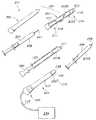
도 2는 본 발명에 의해 고려되는 바와 같은 환자에 대해 수행되는 고주파 절제 절차의 위치파악 정확도를 향상시키기 위한 시스템의 사시도이다.
도 3은 본 발명에서 사용하기 위해 고려되는 하나의 기준 마커의 단면도이다.
도 4는 본 발명에서 사용하기 위해 고려되는 하나의 추가의 기준 마커의 단면도이다.
도 5는 본 발명에서 사용하기 위해 고려되는 다른 기준 마커의 횡단면도이다.
도 6은 본 발명에서 사용하기 위해 고려되는 추가적인 기준 마커의 단면도이다.
본 명세서 및 도면에서의 참조 부호의 반복 사용은 본 발명의 동일한 또는 유사한 특징 또는 요소를 나타내기 위한 것이다.The full and authoritative disclosure of the present invention, including the best mode of the present invention for those skilled in the art, is described in more detail in the remainder of the specification including references to the accompanying drawings.
1 is a block diagram of one method for improving the positioning accuracy of a radiofrequency ablation procedure performed on a patient as contemplated by the present invention.
2 is a perspective view of a system for improving the positioning accuracy of a radiofrequency ablation procedure performed on a patient as contemplated by the present invention.
3 is a cross-sectional view of one fiducial marker contemplated for use in the present invention.
4 is a cross-sectional view of one additional reference marker contemplated for use in the present invention.
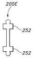
5 is a cross sectional view of another fiducial marker contemplated for use in the present invention.
6 is a cross sectional view of an additional fiducial marker contemplated for use in the present invention.
Repeat use of reference characters in the present specification and drawings is intended to represent the same or similar features or elements of the invention.
본 논의는 예시적인 실시예의 설명에 지나지 않으며 본 발명의 더 넓은 양태를 제한하는 것으로 의도되는 것은 아니라는 것을 통상의 기술자는 이해할 것이다.Those skilled in the art will understand that this discussion is merely illustrative of exemplary embodiments and is not intended to limit the broader aspects of the invention.
일반적으로 말하면, 본 발명은 환자에 대해 수행된 고주파 절제 절차의 위치파악 정확도를 향상시키기 위한 방법 및 시스템에 관한 것이다. 본 발명의 초점은 일시적 신경 차단이 환자에 의해 경험된 통증을 완화한 것을 확증한 후에 절제 절차 동안 일시적 신경 차단이 수행된 정확하게 동일한 거시적 부위로 고주파 에너지를 전달하는 것이다.Generally speaking, the present invention relates to a method and system for improving the positioning accuracy of a radiofrequency ablation procedure performed on a patient. The focus of the present invention is to deliver high frequency energy to exactly the same macroscopic site where transient nerve block was performed during the ablation procedure after confirming that the temporary nerve block alleviated the pain experienced by the patient.
상기 방법은 a) 절제될 목표 신경을 식별하는 단계로서, 목표 신경은 통증의 원인인 것으로 의심되는, 식별 단계; b) 목표 신경을 따르는 신경 신호 전달을 일시적으로 차단하기 위해 목표 신경에 약리학적 작용제를 전달하는 단계; c) 일시적 차단이 환자에 의해 경험되는 통증의 수준을 감소시키는 경우 목표 신경이 통증의 원인이라고 확증하는 단계; d) 일시적 차단이 환자에 의해 경험되는 통증의 수준을 감소시킨다고 확증된 경우에 기준 마커를 목표 신경에 인접하게 배치하는 단계; e) 기준 마커를 위치파악하는 단계; 및 f) 프로브를 통해 기준 마커에 인접하는 조직의 영역으로 고주파 에너지를 전달하는 단계로서, 상기 조직의 영역은 목표 신경에 대응하며 고주파 에너지는 목표 신경을 절제하는데 충분한 수준으로 인가되는, 에너지 전달 단계를 포함한다.The method comprises the steps of: a) identifying a target nerve to be resected, wherein the target nerve is suspected of causing pain; b) delivering a pharmacological agent to the target nerve to temporarily block nerve signal transduction along the target nerve; c) confirming that the target nerve is the cause of the pain if the temporary blockage reduces the level of pain experienced by the patient; d) placing the reference marker adjacent to the target nerve when the temporary blockade is confirmed to reduce the level of pain experienced by the patient; e) locating a reference marker; And f) delivering high frequency energy through a probe to a region of tissue adjacent to the fiducial marker, wherein the region of tissue corresponds to a target nerve and the high frequency energy is applied at a level sufficient to ablate the target nerve. It includes.
한편, 시스템은 외경, 근위 단부, 및 원위 단부를 갖는 프로브로서, 프로브는 근위 단부에 위치된 전기 절연부 및 원위 단부에 위치된 목표 신경에 에너지를 전달하기 위한 도전부를 포함하는, 프로브; 프로브의 원위 단부를 목표 신경에 인접하게 환자 안으로 삽입하는 것을 용이하게 하기 위한 도입기로서, 도입기는 내경, 근위 단부, 및 원위 단부를 갖고, 프로브의 노출 도전부는 목표 신경으로의 에너지 전달 동안 원위 단부를 지나 연장되고, 프로브의 외경 및 도입기의 내경은 루멘을 형성하는, 도입기; 목표 신경을 따르는 신경 신호 전달을 차단하는데 충분한 양으로 공급되는 약리학적 작용제; 및 목표 신경에 인접하게 배치되도록 구성되는 기준 마커를 포함한다. 본원에서 사용될 때, 용어 "원위" 및 "근위"는 디바이스가 사용중일 때 사용자/의료 전문가에 관하여 정의되는 것이다. 즉, 용어 "원위"는 사용자/의료 전문가로부터 더 멀리 있으며 치료 부위에 가장 가까운 부품 또는 부분을 지칭하는 한편, 용어 "근위"는 디바이스가 사용중일 때 사용자/의료 전문가에 더 가깝고 치료 부위로부터 가장 먼 부품 또는 부분을 지칭한다.On the other hand, the system includes a probe having an outer diameter, a proximal end, and a distal end, the probe including an electrical insulator located at the proximal end and a conductive portion for delivering energy to a target nerve located at the distal end; An introducer for facilitating insertion of a distal end of a probe into a patient adjacent to a target nerve, the introducer having an inner diameter, a proximal end, and a distal end, wherein the exposed conducting portion of the probe displaces the distal end during energy transfer to the target nerve. An introducer, extending past, the outer diameter of the probe and the inner diameter of the introducer form a lumen; Pharmacological agents supplied in an amount sufficient to block nerve signal transduction along the target nerve; And a fiducial marker configured to be positioned adjacent to the target nerve. As used herein, the terms "distal" and "proximal" are defined with respect to the user / medical professional when the device is in use. That is, the term "distal" refers to the part or part that is farther from the user / medical professional and closest to the treatment site, while the term "proximal" is closer to the user / medical professional and farthest from the treatment site when the device is in use. Refers to a part or part.
이제 도 1로 시작하여 도면을 참조하면서, 환자에 대해 수행된 고주파 절제 절차의 위치파악 정확도를 향상시키기 위한 방법 및 시스템의 다양한 특징을 더 상세하게 설명한다. 도 1에 도시된 바와 같이, 방법(100)은 목표 신경(102)을 식별하는 단계를 포함하고, 여기서 목표 신경은 통증의 원인인 것으로 의심된다. 목표 신경은 척추의 두개골, 흉추, 요추, 천추 또는 미골 영역의 수준에서의 신체 내의 척수로부터 기원하는 운동, 감각 및 자율 기능을 포함하는 신경과 같은 척수 신경일 수 있다. 추가로, 사지 및 원위 손발가락에 신경을 분포시키는 말초 신경이 목표 신경을 나타낼 수 있다. 상기 방법은 이어서 목표 신경(104)을 따른 신경 신호 전달을 일시적으로 차단하는 단계를 수반한다. 신경은 마취 약물과 같은 약리학적 작용제에 의해 일시적으로 차단될 수 있다. 상기 방법은 이어서 일시적 차단으로 인한 통증의 완화를 확증하는 단계(106)를 수반하고, 여기서 일시적 차단이 환자에 의해 경험되는 통증의 수준을 완화하거나 감소시키는 경우 목표 신경이 통증의 원인인 것으로 확증될 수 있다. 목표 신경이 정확하게 식별되고 위치파악되었음을 나타내는 통증의 완화가 달성되는 경우, 상기 방법은 기준 마커를 목표 신경(108)에 인접하게 배치하는 단계를 더 포함한다. 그리고, 환자가 RF 절제를 통해 1개 이상의 신경 차단과 같은 더 영구적이거나 긴 지속적 신경 차단에 대해 준비되었을 때, 상기 방법은 기준 마커(110)를 위치파악하는 단계를 더 포함하며, 여기서 기준 마커는 초음파검사, 방사선촬영, 형광투시법 등을 통해 위치파악될 수 있다. 그리고 상기 방법은 기준 마커(112)의 위치에서 RF 절제 절차를 수행하는 단계를 포함한다. 목표 신경에 인접한 그 위치에 의해, 기준 마커는 목표 신경이 정확하게 식별될 수 있도록 절제 절차를 수행하는 의료 전문가에게 안내를 제공하여 정확한 위치에서 올바른 목표 신경이 절제되게 한다.Referring now to the drawings, beginning with FIG. 1, various features of the method and system for improving the positioning accuracy of the radiofrequency ablation procedure performed on a patient are described in more detail. As shown in FIG. 1, the
이제 도 2를 참조하면, 전술된 방법(100)을 수행하기 위해 사용될 수 있는 신경 절제 시스템(200)이 더 상세하게 설명된다. 첫 번째로, 시스템(200)은 폐색기(202) 및 도입기(204)를 포함하는 도입기 장치(201)를 포함할 수 있다. 도입기 장치(201)는 일시적 신경 차단을 위한 약리학적 작용제(208)의 전달과 환자의 신체 내로의 기준 마커(220) 및 RF 절제 프로브(224)의 삽입을 도울 수 있다. 예를 들어, 폐색기(202) 및 도입기(204)는 실질적으로 단단하거나 강성적일 수 있으며, 그래서 도입기 장치(201)는 피부 또는 다른 신체 조직을 관통하는 것을 보조할 수 있다. 또한, 폐색기(202)는 도입기(204)와 협력적으로 결합되도록 구조화될 수 있다. 다시 말해서, 폐색기(202)는 도입기의 내경(210)에 의해서 형성된 바와 같은 도입기(204)의 루멘(206) 내에 끼워지도록 크기설정될 수 있으며, 여기서 폐색기(202)는 폐색기(202)를 도입기(204)에 고정하기 위한 수단을 포함할 수 있다. 일 실시예에서, 폐색기(202)가 도입기(204) 내에 완전히 배치될 때, 폐색기(202)는 도입기 장치(201)가 신체 내로 삽입될 때 조직이 루멘(206)에 인입하는 것이 방지되도록 도입기(204)의 루멘(206)을 충분히 폐색한다. 일부 실시예에서, 폐색기(202)의 원위 단부는 첨예하거나 날카로울 수 있다. 이들 실시예에서, 폐색기(202)의 원위 단부는 원추형, 경사형, 또는 더 구체적으로는 삼중 경사형일 수 있다. 폐색기(202) 및 도입기(204)의 길이는 용례에 따라 다양할 수 있다. 일 실시예에서, 도입기(204)는 그 원위 단부(214)가 신체 내의 목표 신경 조직에 도달할 수 있고 반면에 근위 단부(212)는 신체의 외부에 남아 있도록 크기설정될 수 있다. 일부 실시예에서, 목표 신경이 척수 신경일 경우 등에서, 도입기(204)는 약 5.5 인치(13.97 cm) 내지 약 7.5 인치(19.05 cm)의 길이일 수 있고, 폐색기(606)는 약 5.5 인치(13.97 cm) 내지 약 7.5 인치(19.05 cm)의 길이일 수 있다. 더 구체적으로, 도입기(204)는 약 6.4 인치(16.26 cm)의 길이일 수 있고, 폐색기(202)는 약 6.6 인치(16.76 cm)의 길이일 수 있다. 다른 실시예에서, 예로서, 신경이 말초 신경일 때, 도입기(204)는 약 0.5 인치(1.27 cm) 내지 약 2 인치(5.08 cm), 예를 들어 약 0.75 인치(1.91 cm) 내지 약 1.75 인치(4.45 cm), 예를 들어 약 1 인치(2.54 cm) 내지 약 1.5 인치(3.81 cm)일 수 있다. 폐색기(202)는 도입기(204)보다 약간 더 길 수 있어, 폐색기(202)의 원위 단부가 완전히 배치될 때 도입기(204)로부터 돌출할 수 있게 된다. 도입기(204)의 루멘(206)은 또한 절차의 침습성을 제한하기 위해 가능한 한 작게 유지되면서 RF 절제 프로브(224)의 직경을 수용하도록 크기설정될 수 있다. 특정 실시예에서, 도입기(204) 및 폐색기(202)의 근위 단부는 허브 또는 로크와 함께 잠금되도록 구조화된다.Referring now to FIG. 2, a
일 실시예에서, 폐색기(202) 및 도입기(204)는 스테인리스강으로 제조될 수 있다. 다른 실시예에서, 폐색기(202), 도입기(204) 또는 양자 모두는 예를 들어 니켈-티타늄 합금과 같은 다른 재료로부터 제조될 수 있다. 또한, 일부 실시예에서, 폐색기(202)는 폐색기(202)를 에너지 공급원 또는 발생기(234)에 연결하기 위한 수단, 예를 들어 와이어 또는 케이블을 포함할 수 있다. 이러한 실시예에서, 폐색기(202)는 도입기 장치(201)가 환자의 신체 내로 삽입될 때 조직의 임피던스를 측정하도록 동작가능할 수 있다. 추가적으로 또는 대안적으로, 폐색기(202)는 자극 에너지를 목표 신경에 전달하도록 동작가능할 수 있다.In one embodiment, the
또한, 시스템은 약리학적 작용제(208)를 포함할 수 있다. 약리학적 작용제(208)는 목표 신경을 따르는 신경 신호 전달을 일시적으로 차단하기 위해 목표 신경에 전달될 수 있다. 목표 신경을 따르는 신경 신호 전달을 일시적으로 차단함으로써, 일시적 신경 차단은 환자에 의해 경험되는 통증이 일시적 신경 차단 및 환자에 대한 약리학적 작용제(208)의 전달의 결과로서 감소 또는 제거되는 경우 의료 전문가가 올바른 신경(즉, 환자에게 통증을 야기하는 신경)이 식별되었다고 확증할 수 있는 능력을 허용한다. 약리학적 작용제(208)는 임의의 적절한 수단에 의해 목표 신경으로 전달될 수 있다. 예를 들어, 하나의 특정 실시예에서, 약리학적 작용제(208)는 바늘 팁(244)을 갖는 주사기(238)에 저장된다. 폐색기(202)가 도입기(204)의 루멘(206)으로부터 제거된 후에, 주사기(238)는 주사기(238)의 바늘 팁(244)이 목표 신경(즉, 통증의 원인인 것으로 의심되는 신경)에 인접하는 도입기(204)의 원위 단부(214)를 향해 위치설정되도록 도입기(204)의 루멘(206) 내로 삽입될 수 있다. 약리학적 작용제(208)가 목표 신경에서 신경 신호 전달을 일시적으로 차단하기에 충분한 양으로 목표 신경에 전달된 후, 주사기(238)는 제거될 수 있다. 전술한 논의에서 주사기(238)가 사용되지만, 약리학적 작용제(208)는 카테터, IV 백, 펌프, 또는 임의의 다른 적절한 유체 전달 기구를 사용하여 전달될 수 있다는 것을 이해해야 한다.The system can also include a
약리학적 작용제(208)의 전달이 목표 신경을 따르는 신경 신호 전달을 일시적으로 차단하는데 성공하면, 시스템(200)은 환자에 의해 경험되는 통증의 수준을 감소시키거나 제거하기 위해 더 영구적인 신경 차단이 목표 신경에 정밀하고 정확하게 적용될 수 있도록 목표 신경을 표시하기 위해 기준 마커(220)의 사용을 더 고려한다. 기준 마커(220)는, 환자의 통증과 연관된 목표 신경이 올바르게 식별될 때까지 약리학적 작용제(208)가 하나 이상의 위치에서 전달되는 초기 절차 후에 수분, 수시간, 수일, 수주, 또는 심지어 수개월 동안 일어날 수 있는 임의의 후속 신경 차단의 정확도를 향상시킬 수 있다. 기준 마커(220)는 목표 신경 부위(예를 들어, 약리학적 작용제(208)의 전달이 환자의 통증을 감소시키는 부위)로 다양한 방식으로 전달될 수 있다. 일부 실시예에서, 기준 마커(220)는 도입기(204)를 교체 또는 제거하지 않고 도입기(204)를 통해서 목표 신경으로 전달될 수 있고, 여기에서 도입기(204)의 원위 단부(214)는 목표 신경에 인접하여 위치설정된다. 예를 들어, 기준 마커(220)는 고체 재료로부터 형성된 기준 마커 (220A)일 수 있다. 고체 재료는 초음파검사, 방사선촬영 또는 형광투시법을 사용하여 시각화될 수 있는 금속, 폴리머, 세라믹, 또는 임의의 다른 재료일 수 있고, 고체 재료는 재료가 시각화될 수 있게 하기 위해 형광성 재료와 같은 첨가제를 포함할 수 있다. 고체 재료는 분해성일 수 있거나 또는 고체 재료는 비-분해성일 수 있어서 고체 재료는 후속 절차 동안 제거될 수 있다. 기준 마커(220A)가 금속을 포함하는 경우, 금속은 금, 은, 티타늄, 백금 또는 이들의 조합일 수 있다. 기준 마커(220A)가 비금속 재료를 포함하는 경우, 재료는 폴리락트산, 폴리(락트산-코-글리콜릭)산 및 폴리(카프로락톤) 또는 비-펩티드 폴리머와 같은 분해성 펩티드 폴리머 및 실리콘, 폴리에틸렌, 폴리우레탄 및 폴리프로필렌과 같은 비-생분해성 폴리머일 수 있다. 기준 마커는 또한 피브린 또는 콜라겐과 같은 단백질성 생물학적 재료, 키토산, 글리코사미노글리칸 또는 히알루론산과 같은 다당류 재료, 또는 히드록시아파타이트를 포함하는 세라믹과 같은 세라믹을 포함할 수 있다. 또한, 전술된 재료 중 임의의 것이 기준 마커(220A)를 형성하기 위해 임의의 조합으로 사용될 수 있다는 것이 이해되어야 한다.If delivery of the
기준 마커(220A)를 위해 이용된 특정 고체 재료와 관계없이, 기준 마커(220A)는 전개 바늘(240)을 통해서 도입기(204)로부터 목표 신경으로 전달될 수 있다. 기준 마커(220A)는 전개 바늘(240)의 개방 단부(242)에 저장될 수 있고, 여기서 전개 바늘(240)은 목표 신경 또는 목표 신경에 인접한 영역에 대한 기준 마커(220A)의 전달이 요망될 때 개방 단부(242)가 도입기(204)의 원위 단부(214)에 인접하도록 도입기(204)의 루멘(206) 내에 위치설정될 수 있다. 그후 전개 바늘(240) 내에 배치된 로드(222)는 이후의 절차(예를 들어, RF 절제) 동안 목표 신경이 정확하게 위치파악될 수 있도록 목표 신경을 표시하기 위해 전개 바늘(240)의 개방 단부(242)로부터 목표 신경에 인접한 적절한 위치로 기준 마커(220A)를 전개하도록 조작될 수 있다. 로드(222)는 금속 또는 강성 폴리머와 같이 원하는 위치로의 기준 마커(220A)의 조작을 가능하게 하도록 충분히 강성적인 임의의 재료로 형성될 수 있다.Regardless of the specific solid material used for
기준 마커(220)가 도입기(204)를 통해 목표 신경에 전달될 수 있는 다른 실시예에서, 도입기(204)의 원위 단부(214)는 목표 신경에 인접하여 위치설정되고, 기준 마커(220)는 일단 목표 신경에 전달되면 경화되는 액체 기준 마커(220B)일 수 있다. 예를 들어, 액체 기준 마커(220B)는 주입된 후에 또는 달리 목표 신경에 인접하게 배치된 후에 경화하는 액체 폴리머일 수 있다. 액체 기준 마커(220B)는 바늘 팁(254)을 갖는 주사기(246)에 저장될 수 있고, 주사기(246)는 바늘 팁(254)을 통해 목표 신경에 액체 기준 마커(220B)를 전달하기 위해 도입기(206)의 루멘(206) 내에 끼워진다. 예를 들어, 액체 기준 마커(220B)는 히드로겔일 수 있고 그리고/또는 분해성일 수 있다. 사용될 수 있는 생분해성 히드로겔 기준 마커의 예가 Fisher 등의 미국 특허 제7,329,414호에 설명되어 있다. 구체적으로, 액체 기준 마커(220B)는 아이오딘, 라듐, 베릴륨, 또는 다른 방사선불투과성 조영제가 포함된 히드로겔일 수 있다. 본 발명에 의해 고려되는 액체 기준 마커(220B)의 다른 예는 아이오딘화된 폴리에틸렌 글리콜 히드로겔 입자를 포함하는, 매사추세츠주 월섬의 Augmenix, Inc.로부터 입수가능한 TraceIT® 기준 마커와 같은 주입가능 방사선불투과성 히드로겔이다. 이러한 마커는 약 3개월 동안 보이며, 그 후에 입자는 액화되어 흡수되며 환자의 소변으로 제거된다.In another embodiment in which the fiducial marker 220 can be delivered to the target nerve through the
다른 실시예에서, 기준 마커(220)는 전술한 바와 같은 고체 재료로 형성될 수 있고 도입기(204)를 교체 또는 제거하지 않고 도입기(204)의 외면(218) 상에 배치될 수 있고, 여기서 도입기(204)의 원위 단부(214)는 목표 신경에 인접하여 위치설정된다. 예를 들어, 도 2에 도시된 바와 같이, 기준 마커(220D)는 도입기(204)의 외경(216) 주위를 감쌀 수 있고, 도입기(204)의 원위 단부(214)가 목표 신경과 접촉하게 될 때, 기준 마커(220D)는 목표 신경 상으로 "파지"될 수 있고, 도입기(204)의 제거 후에 목표 신경을 표시하기 위해 제 위치에 유지될 수 있다. 기준 마커(220D)는 도시된 바와 같이 나선형 형상을 가질 수 있지만, 임의의 다른 적합한 형상이 또한 사용될 수 있다. 예를 들어, 기준 마커(220D)는 기준 마커(220D)가 약물 또는 에너지 전달의 부위에서 목표 신경을 가리키도록 c-형상, 링-형상, 또는 선형일 수 있다.In another embodiment, the fiducial marker 220 may be formed of a solid material as described above and disposed on the
이제 도 3, 도 4 및 도 5를 참조하면, 본 발명은 또한 부속물(252)을 포함하는 기준 마커(220D, 220E, 및 220F)를 각각 고려한다. 부속물(252)은 기준 마커(220D, 220E, 및 200F)를 목표 신경에 인접한 제 위치에 고정하고 기준 마커의 이동을 방지하는 것을 도와서, 목표 신경이 일시적 신경 차단 후의 추후의 절차(예를 들어, 하나 이상의 RF 절제 절차)를 위해 정확하고 정밀하게 식별될 수 있게 한다. 임의의 적합한 형상 또는 설계가 부속물(252)을 위해 사용될 수 있지만, 도 3은 바벨-유사 형상을 갖는 기준 마커(220D)를 고려하며, 여기서 바벨의 단부를 목표 신경 또는 목표 신경에 인접한 조직 내로 밀어 넣을 수 있다. 도 4의 기준 마커(220E)는 기준 마커(220E)를 제 위치에 고정하는 것을 추가로 돕는 반원형 부속물이 추가된 유사한 바벨-유사 형상을 갖는다. 한편, 도 5의 기준 마커(220F)는 기준 마커(220F)의 길이의 양 측면을 따라 삼각형-형상 부속물(252)을 포함하고, 여기서 삼각형-형상 부속물(252)은 기준 마커(220F)가 이동하지 않고 목표 신경을 정확하게 표시하도록 신경 조직을 파지하는 치형부로서 작용할 수 있다.Referring now to FIGS. 3, 4, and 5, the present invention also contemplates reference markers 220D, 220E, and 220F, each including an
기준 마커(220G)가 더 얇은 연결 지점에 의해 결합되는 다수의 "시드(seed)"를 갖는 기준 마커를 위한 또 다른 설계가 도 6에 도시되어 있다. 시드는 다수의 기준 지점을 제공할 수 있고, 더 얇은 연결 지점은 목표 신경에 인접한 기준 마커(220G)의 배치를 조작하기 위해 소정 정도의 가요성을 기준 마커(220G)에 제공한다.Another design for a fiducial marker with multiple “seeds” to which fiducial markers 220G are joined by thinner connection points is shown in FIG. 6. The seed can provide a number of reference points, with thinner connection points providing a degree of flexibility to the reference marker 220G to manipulate the placement of the reference marker 220G adjacent to the target nerve.
위에서 언급된 바와 같이, 도입기 장치(201), 약리학적 작용제(208) 및 기준 마커(220)에 추가하여, 본 발명에 의해 고려되는 시스템(200)은 RF 절제 프로브(224)를 또한 포함할 수 있다. 프로브(224)는 RF 에너지를 목표 신경에 전달하기 위해 사용될 수 있고, 목표 신경은 초음파검사, 방사선촬영, 형광투시법 등에 의해 기준 마커(220)를 위치파악함으로써 정확하게 위치파악된다. 도 2는 RF 절제 디바이스가 능동형 프로브 팁(248)을 갖는 프로브(224)일 수 있는 것을 나타내지만, 다른 실시예에서 RF 절제 디바이스는 환자의 신체 내의 목표 부위에 에너지를 전달할 수 있는 캐뉼라, 카테터 또는 임의의 다른 세장형 부재일 수 있다. 명료화를 위해, 용어 "프로브"는 임의의 이러한 디바이스를 설명하기 위해 명세서 전체에 걸쳐 사용된다. 프로브(224)는 근위 단부(226) 및 원위 단부(228)를 갖는 세장형 부재일 수 있고, 여기서 "원위"라는 용어는 사용자로부터 더 먼 그리고 치료 부위에 가장 가까운 부품 또는 부분을 지칭하며, "근위" 라는 용어는 디바이스가 사용 중일 때 사용자에게 더 가깝고 치료 부위로부터 가장 먼 부품 또는 부분을 지칭한다.As mentioned above, in addition to the
도 2에 도시된 바와 같이, 프로브(224)는 전기 절연부(230) 및 전기 노출 도전부(232)를 포함할 수 있다. 전기 노출 도전부(232)는 또한 활성 전극이라 지칭될 수 있고, 노출 도전부(232)가 프로브(224)의 원위 단부(228)에 위치될 때, 이는 활성 팁(248)이라 지칭될 수 있다. 일반적으로, 전기 절연부(230)는 프로브(224)의 근위 단부(226)로부터 프로브(224)의 원위 단부(228)에 인접한 위치까지 연장될 수 있다. 전기 절연부(230)가 연장되는 위치는 용례에 의존할 수 있다. 더욱이, 전기 절연부(230)가 연장되는 위치는 고정되지 않을 수 있다. 또한, 일부 실시예에서, 프로브(224)는 하나 초과의 전기 절연부(230) 및/또는 하나 초과의 전기 노출 도전부(232)를 포함할 수 있다.As shown in FIG. 2, the
일부 실시예에서, 구체적으로 도시되지는 않았지만, 프로브(224)의 근위 단부(226)는 도입기, 커넥터 케이블, 캐뉼라, 튜브 또는 다른 허브와 같은 다른 디바이스를 예를 들어 프로브(224)에 견고하게 연결하도록 구조화될 수 있는 허브를 포함할 수 있다. 예를 들어, 프로브(224)는 허브와 연계될 수 있는 각각의 연결 수단(예를 들어, 전기 케이블 및/또는 가요성 튜빙)을 통해 에너지 공급원(234)에 그리고/또는 냉각 공급원에 결합될 수 있다. 허브는 또한 프로브(224)를 위한 손잡이 또는 파지부로서의 역할을 할 수 있으며 프로브(224)를 도입기(204)에 고정하기 위한 잠금 기구로서의 역할을 할 수 있다. 허브는 플라스틱, 폴리머, 금속, 또는 이들의 조합을 포함하지만 이것으로 한정되지 않는 다수의 상이한 재료로부터 제조될 수 있다. 더욱이, 허브는 다수의 상이한 수단에 의해 프로브(224)에 부착될 수 있다. 예를 들어, 일 실시예에서, 허브는 폴리프로필렌으로 제조될 수 있고, 루어 피팅(luer fitting)과 같은 임의의 적합한 피팅에 의해 프로브(224)에 부착될 수 있다. 허브는 핸들로서의 역할을 할 수 있지만, 별도의 핸들이 또한 고려된다는 것도 이해되어야 한다.In some embodiments, although not specifically shown, the
프로브(224)의 크기 및 형상은 용례에 따라 상이할 수 있고, 본 발명은 이와 관련하여 한정되는 것은 아니다. 예를 들어, 일부 실시예에서, 프로브(224)의 횡단면 형상은 실질적으로 원형일 수 있다. 다른 실시예에서, 단면 형상은 실질적으로 다각형, 타원형, 또는 임의의 다른 원하는 형상일 수 있다. 일부 실시예에서, 프로브(224)의 원위 단부(228)로부터 근위 단부(226)까지의 길이는 약 5 센티미터(cm) 내지 약 40 cm일 수 있고, 프로브(224)의 외경(250)은 약 0.65 밀리미터(mm) 내지 약 2.00 mm(약 20 AWG 내지 약 12 AWG)일 수 있다. 일 특정 예에서, 프로브(224)의 길이는 약 7.5 cm일 수 있고, 외경은 약 1.5 mm일 수 있으며, 횡단면 형상은 실질적으로 원형일 수 있다. 또한, 원위 단부(228)의 형상은 용례에 따라 상이할 수 있다는 것이 이해되어야 한다. 가능한 형상은 무딘형, 둥근형, 날카로운형, 및 경사형을 포함하지만, 이들에 한정되는 것은 아니다.The size and shape of the
프로브(224)는 강성 또는 가요성일 수 있고, 그 길이를 따른 하나 이상의 점에서 직선형이거나, 굴곡되거나, 또는 각을 이룰 수 있다. 본원에서 사용될 때, 용어 "굴곡"은 점진적이거나 또는 급격하며 그리고 임의의 각도에 있는 종축으로부터의 임의의 편차 또는 임의의 비선형적인 구역을 지칭한다. 프로브(224)가 굴곡되어 있는 실시예에서, 굴곡은 프로브(224)를 따른 다양한 위치, 예를 들어 원위 단부(228)에 있을 수 있다. 더욱이, 굴곡은 다양한 정도 및 길이를 가질 수 있다. 예를 들어, 굴곡은 원의 약 25°를 횡단할 수 있고, 약 5 mm의 길이에 걸쳐 발생할 수 있다. 또한, 프로브(224)는 동일한 평면에 있을 수 있거나 또는 있지 않을 수 있는 복수의 굴곡을 포함할 수 있다. 예를 들어, 일부 실시예에서, 프로브(224)는 나선형 또는 "코르크스크류(corkscrew)" 형상이 되도록 굴곡될 수 있다. 일부 실시예에서, 프로브(224)는 그 형상이 절차의 과정 전에 또는 중에 사용자에 의해 변형될 수 있도록 구조화될 수 있다. 더 구체적으로, 원위 단부(228)의 형상은 예를 들어 작동 메커니즘을 사용하여 직선으로부터 굴곡 구성으로 변화할 수 있도록 변형될 수 있다. 이는 신체 내의 부위에 도달이 어려운 접근을 도울 수 있고, 다양한 수단에 의해 성취될 수 있다. 예를 들어, 프로브(224)는 이들에 한정되는 것은 아니지만, 하나 이상의 견인 와이어, 유압 또는 압전 디바이스, 또는 다른 작동 메커니즘을 포함하는 적어도 하나의 능동 형상 제어 메커니즘을 포함할 수 있다.The
일 실시예에서, 전기 절연부(230)는 전기 절연 코팅, 커버링, 또는 외장으로 프로브(224)의 일부를 피복함으로써 형성될 수 있다. 달리 말하면, 프로브(224)는 세장형 부재의 표면 상에 배치된 전기 절연 재료를 포함할 수 있다. 예를 들어, 일 실시예에서, 프로브(224)는 예를 들어, 폴리테트라플루오로에틸렌(PTFE)과 같은 절연 코팅에 의해 부분적으로 중첩될 수 있는 생체적합성 금속 또는 합금, 예를 들어 스테인리스강으로부터 제조될 수 있다. 다른 실시예에서, 프로브(224)는 니티놀 또는 티타늄과 같은 다른 금속으로부터 제조될 수 있고, 그리고/또는 이에 한정되는 것은 아니지만 폴리에틸렌 테레프탈레이트(PET)를 포함하는 다른 전기 절연 재료가 그 위에 배치될 수 있다. 다른 실시예에서, 다른 금속 또는 전기 절연 재료가 사용될 수 있고, 본 발명은 이와 관련하여 한정되는 것은 아니다. 또는, 절연 재료는 반다공성일 수 있어, 절연 재료를 통한 전류의 일부 누설을 허용한다. 일부 실시예에서, 재료는 또한 단열체일 수 있다. 또 다른 실시예에서, 다양한 절연 재료가 프로브(224)의 다양한 부분에 사용될 수 있다. 절연 코팅은 예를 들어, 침지 코팅, 스프레이 또는 열 수축에 의해 프로브(224)의 일부에 도포될 수 있다. 한편, 프로브(228)의 원위 단부(228)의 나머지 미코팅부는 전기 노출 도전부(232)로서의 역할을 할 수 있다.In one embodiment, the
다른 실시예에서, 프로브(224)는 절연성 또는 비-도전성 재료로부터 제조될 수 있고, 하나 이상의 외부적으로 도포된 전극(도시되지 않음)을 구비할 수 있다. 이러한 실시예에서, 프로브(224)는 일 단부에서 전극(들)에 부착될 수 있고 프로브(224)의 길이를 따라 근위방향으로 연장될 수 있는 하나 이상의 와이어를 포함할 수 있으며, 그래서 와이어(들)의 근위부는 에너지 공급원에 동작식으로 연결되어 전극에 에너지를 공급할 수 있다. 예를 들어, 프로브(224)는 RadelTM 플라스틱으로부터 제조될 수 있으며, 외부적으로 도포된 전극은 스테인리스강으로부터 제조될 수 있다.In other embodiments, the
대안적인 실시예에서, 프로브(224)는 재료의 조합으로부터 제조될 수 있다. 예를 들어, 프로브(224)의 원위 단부(228)는 니티놀과 같은 재료로부터 제조될 수 있어, 원위 단부(228)의 형상이 변경될 수 있게 되고, 프로브(224)의 나머지 부분은 스테인리스강으로 제조될 수 있어, 프로브(224)의 나머지 부분은 실질적으로 고정될 수 있게 된다.In alternative embodiments,
일부 실시예에서, 프로브(224)는 냉각될 수 있다. 일부 특정 실시예에서, 프로브(224)는 냉각 유체의 내부 순환에 의해 냉각될 수 있다. 냉각 매체가 프로브(224)의 원위 단부(228)로부터 나오지 않게 되는 구성을 내부 냉각식 프로브라 지칭할 수 있다. 냉각 유체는 물과 같은, 수술 중에 프로브(224)로부터 열을 제거하기 위해 적합한 임의의 유체일 수 있다. 냉각 유체의 다른 예는 액체 질소 및 염수를 포함하지만, 이들에 한정되는 것은 아니다. 더욱이, 냉각 유체는 수술 중에 프로브로부터 열을 제거하기 위해 적합한 임의의 온도, 예를 들어 약 0℃ 내지 약 25℃에 있을 수 있다. 더 구체적으로, 유체의 온도는 용례에 따라, 약 실온(21℃), 약 4℃, 또는 약 0℃에 있을 수 있다.In some embodiments,
게다가, 냉각 유체는 광범위한 유량으로 전달되거나 순환될 수 있고, 본 발명은 이와 관련하여 한정되는 것은 아니다. 다른 인자들 중에서도, 프로브(224)의 전도도 및 열 용량, 냉각 유체 및/또는 조직, 프로브(224)의 내부 구조, 및 프로브(224)의 원위 단부(228)의 원하는 온도를 포함하는 다수의 인자에 기초하여, 적절한 유량이 결정되거나 계산될 수 있다. 일부 실시예에서, 냉각 유체는 약 10 밀리리터/분(ml/min) 내지 약 30 ml/min의 범위의 유동으로 전달될 수 있다.In addition, the cooling fluid can be delivered or circulated at a wide range of flow rates, and the invention is not limited in this regard. Among other factors, a number of factors including the conductivity and heat capacity of the
프로브(224)를 냉각하기 위한 수단은, 예를 들어 전술된 바와 같이, 냉각 유체의 순환, 열전 회로에 의한 냉각, 또는 흡열 반응에 의한 화학적 냉각을 포함할 수 있지만, 이들에 한정되는 것은 아니다. 일부 실시예에서, 프로브(224)는 열전 회로에 의해 냉각될 수 있다. 예를 들어, 프로브(224)는 2개의 접합부에서 함께 접합되는 2개의 상이한 금속 또는 반도체, 예를 들어 P- 및 N-도핑된 비스무스-텔룰라이드를 포함하는 회로를 부분적으로 또는 완전히 수용할 수 있다. 전류가 회로를 통해 통과할 때, 열이 일 접합부로부터 다른 접합부로 전달될 수 있다. 이 현상은 펠티에 효과(Peltier Effect)로서 공지되어 있다. 열이 그로부터 전달되는 접합부는 프로브(224)의 원위 단부(228)에 위치될 수 있고, 열이 그로 전달되는 접합부는 프로브(224)의 근위 단부(226) 또는 프로브(224)의 외부에 위치될 수 있다. 에너지는 예를 들어, 외부 에너지 공급원(234)(예를 들어, 프로브(224)에 RF 에너지를 전달하는 동일한 에너지 공급원), 전기 발생기 또는 배터리에 의해 회로에 제공될 수 있다.Means for cooling the
대안적인 실시예에서, 프로브(224)는 화학적으로 냉각될 수 있고, 여기서 프로브(224)는 혼합될 때 흡열 반응 또는 흡열 혼합이 일어나서 열 에너지가 흡수되고 프로브(224)의 원위 단부(228)가 냉각되도록 냉각이 요망될 때 혼합될 수 있는 2개 이상의 별도의 재료를 포함할 수 있다. 흡열 반응의 생성물(들) 또는 결과적인 혼합물은 근위 단부(226)를 통해서 프로브(224)를 나올 수 있다.In alternative embodiments, the
또 다른 실시예에서, 도입기(204)는 일시적 신경 차단(예를 들어, 약리학적 작용제(208))을 환자의 신체에 전달하기 위해서 그리고/또는 전술한 바와 같은 프로브(224)의 삽입을 용이하게 하기 위해서 이용될 수 있을뿐만 아니라, 도입기(204)는 환자의 신체에 에너지를 전달하기 위해서도 이용될 수 있다. 도입기(204)가 에너지를 전달하기 위해 사용되는 실시예에서, 도입기(204)는 적어도 하나의 전기 노출 도전부 및 적어도 하나의 전기 절연부를 포함할 수 있다. 일부 실시예에서, 도입기(204)의 본체는 절연 영역을 형성하는 절연성 외장 또는 코팅이 적어도 부분적으로 위에 놓여 있는 도전성 재료로부터 구성될 수 있지만, 일부 실시예에서, 도입기(204)는 하나 이상의 도전성 본체 또는 전극이 외부적으로 적용되는 상태로 절연 재료로부터 구성될 수 있다. 도입기(204)의 원위 단부(214)는 날카롭거나 첨예할 수 있다. 예를 들어, 도입기(204)의 원위 단부(214)는 경사면(bevel)을 포함할 수 있다. 일 실시예에서, 적어도 하나의 전기 절연부는 도입기(204)의 근위 단부(212)로부터 도입기(204)의 원위 단부(214)로 연장될 수 있어, 도입기(204)의 원위면이 적어도 하나의 노출 도전부를 포함하게 된다. 경사면을 포함하는 실시예에서, 적어도 하나의 노출 도전부는 경사면을 포함할 수 있다. 대안적인 실시예에서, 노출 도전부는 대안적으로 또는 추가적으로 도입기(204)의 측면 상에 위치될 수 있다. 일부 실시예에서, 전기 절연부는 도입기(204)의 경사면의 힐부(heel)로 연장할 수 있는 한편, 다른 실시예에서 절연부는 도입기(204)를 따라 더 근위측에서 종료할 수 있다.In another embodiment,
일부 실시예에서, 도입기(204)는 직선형인 반면에, 일부 다른 실시예에서 도입기(204)는 굴곡될 수 있다. 예를 들어, 일부 이러한 실시예에서, 도입기는 도입기(204)의 원위 단부(214)에서 약 5° 내지 약 20° 굴곡을 가질 수 있다. 일부 실시예에서, 도입기(204)는 약 16 내지 약 18 AWG, 약 75 내지 약 150 mm 길이일 수 있고, 전기 노출 도전부는 약 2 mm 내지 6 mm 길이이다. 이들 실시예에서, 프로브(224)는 도입기(204)의 루멘(206) 내에 배치되도록 그리고 도입기(204) 내에 완전히 배치될 때 도입기(204)와 전기 접촉하도록 구조화될 수 있다.In some embodiments,
프로브(224)는 예를 들어 전술된 바와 같이 전기 도전성 세장형 샤프트, 에너지 공급원에 연결하기 위한 연결 수단, 및 냉각 공급부에 연결하기 위한 연결 수단을 포함할 수 있다. 따라서, 에너지가 에너지 공급원에 의해 프로브(224)에 공급될 때, 에너지는 도입기(204)의 도전부를 따라 흐르고 목표 치료 부위에 전달되어, 조직 또는 신체를 통해 기준 또는 리턴 전극으로 이동한다. 이러한 실시예에서, 프로브(224)의 샤프트는 전기 도전성일 수 있으며 실질적으로 프로브(224)의 전체 길이를 따라 노출될 수 있다. 달리 말하면, 도입기(204)와 함께 이러한 실시예에서 사용되는 프로브(224)는 전술된 바와 같은 전기 절연성 코팅(230)을 포함하지 않을 수 있다.The
일부 실시예에서, 프로브(224)의 원위 단부(228)는 도입기(204) 내에 완전히 배치될 때 도입기(204)의 원위 단부(214)와 실질적으로 동일한 높이에 있을 수 있다. 다른 실시예에서, 프로브(224)의 원위 단부(228)는 도입기(204) 내에 완전히 배치될 때 도입기(204)의 원위 단부(214)로부터 원위측으로 연장될 수 있다. 다른 실시예에서, 프로브(224)의 원위 단부(228)는 도입기(204)에 완전히 배치될 때 도입기(204)의 원위 단부(214)로부터 근위측으로 오목해질 수 있다. 본 명세서에 사용될 때, "완전히 배치"라는 구문은 제1 부재가 제2 부재 내에 실질적으로 완전히 수용되어, 통상 사용 중에 제2 부재 내로 더 이상 삽입되지 않게 되는 것을 지칭한다.In some embodiments,
프로브(224) 및 도입기(204)는, 프로브(224)가 도입기(204) 내부에 완전히 위치설정되거나 도입기 내에 배치될 때, 프로브(224)의 적어도 일부가 도입기(204)의 적어도 일부와 전기 및/또는 열 접촉하게 되어, 열 및/또는 전기 에너지가 프로브(224)로부터 도입기(204)로 전달될 수 있게 되도록 구조화될 수 있다. 이는 액체의 층이 프로브(224)의 적어도 일부와 도입기(204) 사이에 남아 있도록 프로브(224)를 삽입하기 전에 염수와 같은 액체로 도입기(204)를 플러싱함으로써 성취될 수 있다. 염수는 이어서 프로브(224)와 도입기(204) 사이에서 전기 및/또는 열을 전도하는 역할을 할 수 있다. 대안적으로, 프로브(224) 및 도입기(204)는, 프로브(224)가 도입기(204) 내에 완전히 배치될 때 물리적으로 접촉하여, 전기적 및 열 접촉이 또한 이루어지도록 구조화될 수 있다. 추가의 실시예에서, 프로브(224)의 일부가 도입기(204)의 도전부와 열 접촉할 수 있다. 이는 프로브(224)의 냉각이 도입기(204)의 도전부가 냉각되는 것을 허용할 것이라는 점에서 유리할 수 있다. 프로브(224)는 전술된 바와 같이 다양한 방법에 의해 냉각될 수 있다.The
일부 실시예에서, 프로브(224)는 에너지 공급원(234), 예를 들어 발생기(234)에 동작식으로 연결되도록 구조화될 수 있다. 프로브(224)를 발생기(234)에 연결하기 위한 연결 수단(236)은 하나 이상의 전기적 연결을 행하도록 동작가능한 임의의 구성요소, 디바이스, 또는 장치, 예를 들어 절연 와이어 또는 케이블을 포함할 수 있다. 일 실시예에서, 연결 수단(236)은 프로브(224)의 근위 단부(226)에서 종결되는 전기 케이블을 포함할 수 있다. 커넥터는 예를 들어 중간 케이블을 통해 직접적으로 또는 간접적으로 에너지 공급원(234)에 연결되도록 동작가능할 수 있다. 케이블(236)과 연계된 적어도 하나의 와이어 또는 다른 전기 도전체가, 에너지 공급원(234)으로부터 프로브(224)로 에너지를 공급하기 위해, 예를 들어 크림프 또는 땜납 연결에 의해, 프로브(224)의 도전부에 결합될 수 있다. 일 특정 실시예에서, 4-핀 의료용 커넥터가 케이블(236)을 중간 케이블(도시되지 않음)에 연결하기 위해 사용될 수 있으며, 중간 케이블은 에너지 공급원/발생기(234)에 연결될 때 자동적으로 식별될 수 있는 14-핀 커넥터에 더 부착될 수 있다.In some embodiments,
에너지 공급원/발생기(234)는 다양한 종류의 에너지, 예를 들어 마이크로파, 초음파, 광학, 또는 고주파 전기 에너지를 생성할 수 있다. 일부 실시예에서, 발생기(234)는 약 1 와트 내지 약 50 와트의 전력에서, 약 10 kHz 내지 약 1000 kHz의 주파수를 갖는 고주파 전류를 생성할 수 있다. 일부 실시예에서, 발생기(234)는 그 내에 통합된 디스플레이 수단을 포함할 수 있다. 디스플레이 수단은, 이들에 한정되는 것은 아니지만, 온도, 전력 또는 임피던스와 같은 치료 절차에 관련되는 임의의 파라미터 및 치료 절차에 관련된 에러 또는 경고를 포함하는, 치료 절차의 다양한 양태를 표시하도록 동작가능할 수 있다. 대안적으로, 발생기(234)는 외부 디스플레이에 신호를 전송하기 위한 수단을 포함할 수 있다. 일 실시예에서, 발생기(234)는 하나 이상의 디바이스, 예를 들어 하나 이상의 프로브(224) 및/또는 하나 이상의 냉각 공급원(도시되지 않음)과 통신하도록 동작가능할 수 있다. 이러한 통신은 사용된 디바이스 및 수행된 절차에 따라 단방향성 또는 양방향성일 수 있다. 에너지 공급원의 실시예에 관한 추가의 상세는 Leung 등의 미국 특허 제8,882,755호 및 Shah 등의 미국 특허 제7,258,688호에 개시되어 있는데, 이들 양자 모두는 본 명세서에 참조로 이미 통합되어 있다.The energy source /
발생기(234)와 본 발명의 시스템의 다른 디바이스 사이의 통신의 예로서, 발생기(234)는 하나 이상의 온도 감지 디바이스(도시되지 않음)로부터 온도 측정치를 수신할 수 있다. 온도 측정치에 기초하여, 발생기(234)는 프로브(들)에 송신되는 전력을 변조하는 것과 같은 일부 동작을 수행할 수 있다. 예를 들어, 프로브(들)로의 전력은, 미리규정된 임계 수준에 비해, 온도 측정치가 낮을 때 증가될 수 있거나 또는 측정치가 높을 때 감소될 수 있다. 하나 초과의 프로브가 사용되면, 발생기(234)는 각각의 프로브와 연계된 온도 감지 디바이스로부터 수신된 개별 온도 측정치에 따라 각각의 프로브에 송신된 전력을 독립적으로 제어하도록 동작가능할 수 있다. 일부 경우에, 발생기(234)는 하나 이상의 프로브(들)(224)로의 전력을 종료할 수 있다. 따라서, 일부 실시예에서, 발생기(234)는 하나 이상의 프로브(들)로부터 신호(예를 들어, 온도 측정치)를 수신하고, 적절한 동작을 결정하며, 하나 이상의 프로브(들)로 역으로 신호(예를 들어, 감소된 또는 증가된 전력)를 송신할 수 있다.As an example of communication between
대안적으로, 하나 이상의 냉각 수단(즉, 냉각 공급원)이 하나 이상의 펌프(도시되지 않음)를 포함하는 경우, 하나 이상의 펌프는 소정의 냉각 유체 유량을 발생기(234)에 보낼 수 있고, 예를 들어 발생기(234)에 의해 수신된 온도 측정치에 따라 이 유량을 조절하도록 펌프(들)에 지시하는 통신을 발생기(234)로부터 수신할 수 있다. 일부 실시예에서, 펌프(들)는 유량을 변화시킴으로써 또는 소정 시간 기간 동안 꺼짐으로써 발생기(234)에 응답할 수 있다. 펌프는 프로브(224)를 둘러싸는 조직의 온도가 평형상태에 도달하게 하기 위해 꺼질 수 있어, 주위 조직 온도의 더 정밀한 결정이 이루어질 수 있게 한다. 게다가, 하나 초과의 프로브(224)를 사용할 때, 발생기(234)가 각각의 프로브(224)를 독립적으로 제어하지 않는 실시예에서, 프로브(들)(224)와 연계된 온도 감지 디바이스 내의 평균 온도 또는 최대 온도가 냉각 수단을 제어하는데 사용될 수 있다.Alternatively, if one or more cooling means (ie, a cooling source) comprises one or more pumps (not shown), the one or more pumps may send a predetermined cooling fluid flow rate to
일부 실시예에서, 본 발명의 시스템은 하나의 프로브(224)를 포함할 수 있고; 다른 실시예에서, 본 발명의 시스템은 복수의 프로브, 예를 들어 2개의 프로브를 포함할 수 있다. 시스템은, 예를 들어 단극 모드, 쌍극 모드, 또는 다상/다극 모드에서 동작될 수 있다. 단극 모드에서 동작될 때, 임의의 수의 프로브가 사용될 수 있고, 시스템은 분산형 리턴 전극을 더 포함할 수 있다. 분산형 리턴 전극은 예를 들어, 환자의 피부에 부착되는 접지 패드일 수 있거나, 또는 프로브(224)와 일체형인 상당히 대형인 전극일 수 있다. 시스템이 쌍극 모드에서 동작될 때, 임의의 수의 프로브, 예를 들어 2개의 프로브가 사용될 수 있고, 전류가 프로브 사이에서 이동할 수 있다. 대안적으로, 하나의 프로브(224)가 사용될 때, 전류가 도전부(232)와 프로브(224) 상의 제2 전기 도전성 노출부 사이에서 이동할 수 있다. 예를 들어, 프로브(224)는 도전부(232)에 대해 근위측의 위치에서 프로브(224) 주위에 배치되어 있는 링의 형태의 제2 전기 도전성 노출부를 포함할 수 있다. 도전부(232) 및 제2 전기 도전성 노출부는 서로로부터 전기적으로 격리될 수 있고, 프로브(2224)는 제2 전기 도전성 노출부를 도전부(232)와 상이한 전위에 있는 에너지의 공급원 또는 회로 접지에 동작식으로 연결하기 위한 수단을 포함할 수 있다.In some embodiments, the system of the present invention may include one
시스템의 동작은 사용자에 의해 수동적으로 제어될 수 있거나, 또는 특정 파라미터에 기초하여, 예를 들어 시스템 자체의 구성요소의 특성 또는 치료되는 조직의 특성의 측정치에 기초하여 자동적으로 제어될 수 있다. 하나 초과의 프로브가 사용될 때, 시스템의 동작을 제어하는 수단은, 예를 들어 임의의 프로브로의 전류 흐름이 독립적으로 조정될 수 있도록 각각의 프로브를 독립적으로 제어하도록 구성될 수 있다. 또한, 냉각의 유동이 각각의 프로브로 독립적으로 제어될 수 있다. 따라서, 하나의 프로브가 다른 프로브 또는 프로브들에 비해 더 고온에 있는 것으로 판명되면, 그 프로브로의 냉각의 유동은 증가될 수 있고 그리고/또는 그 프로브로의 전류 흐름이 감소될 수 있다. 유사하게, 하나의 프로브가 다른 프로브 또는 프로브들에 비해 더 저온에 있는 것으로 판명되면, 그 프로브로의 냉각의 유동은 감소될 수 있고 그리고/또는 그 프로브로의 전류 흐름이 증가될 수 있다. 자동 제어를 갖는 시스템의 실시예에서, 시스템은 지정된 기준에 기초하여 하나 이상의 디바이스를 제어하도록 동작가능한 제어기를 포함할 수 있다. 시스템의 자동적 또는 수동적 제어에 관한 추가의 상세는 Leung 등의 미국 특허 제8,882,755호에 제공되어 있다.The operation of the system may be controlled manually by the user, or may be automatically controlled based on certain parameters, for example based on measurements of the properties of the components of the system itself or the properties of the tissue being treated. When more than one probe is used, the means for controlling the operation of the system may be configured to independently control each probe, for example so that the current flow to any probe can be independently adjusted. In addition, the flow of cooling can be controlled independently with each probe. Thus, if one probe is found to be at a higher temperature than other probes or probes, the flow of cooling to that probe can be increased and / or the current flow to that probe can be reduced. Similarly, if one probe is found to be cooler than other probes or probes, the flow of cooling to that probe may be reduced and / or the current flow to that probe may be increased. In an embodiment of a system with automatic control, the system can include a controller operable to control one or more devices based on specified criteria. Further details regarding automatic or manual control of the system are provided in US Pat. No. 8,882,755 to Leung et al.
일반적으로, 본 발명의 방법의 실시예는, 환자에 의해 경험된 통증의 수준을 감소시키도록, 목표 신경(예를 들어, 척수 신경)을 따른 신경 신호 전달을 효과적으로 차단하는 충분한 크기 및 적합한 기하형상의 병변을 형성하기 위해 환자의 신체의 특정 영역 내에서 치료 디바이스, 예를 들어 프로브를 포함하는 전기수술 디바이스를 사용하는 단계를 수반한다. 예를 들어, 하나의 넓은 양태에서, 목표 신경을 절제하기 위해서 종축을 갖는 전기수술 디바이스를 사용하여 인간 또는 동물의 신체 내의 목표 부위에 병변을 생성하는 방법이 제공된다. 절제 절차는, 도입기를 통해 신체 내로 프로브를 삽입하는 단계; 액체 도입 장치(예를 들어, 주사기, IV 백 등)로부터 액체(예를 들어, 치료제, 염수 등)를 포트 내로 그리고 도입기의 원위 단부를 통해 전달하는 단계; 전기수술 디바이스에 배출구를 제공하기 위해 액체 도입 장치를 선택적으로 제거하는 단계; 및 목표 신경에 병변을 생성하기 위해 에너지 공급원으로부터 도입기의 원위 단부를 통해 목표 신경에 에너지를 전달하는 단계를 포함할 수 있고, 프로브는 냉각식 프로브이다.In general, embodiments of the methods of the present invention are of sufficient size and suitable geometry to effectively block nerve signal transduction along a target nerve (eg, spinal nerve) to reduce the level of pain experienced by the patient. The use of an electrosurgical device comprising a therapeutic device, eg a probe, within a particular area of the patient's body to form a lesion of the patient is involved. For example, in one broad aspect, a method is provided for creating a lesion at a target site within a human or animal body using an electrosurgical device having a longitudinal axis to ablate the target nerve. The ablation procedure may include inserting a probe into the body through an introducer; Delivering liquid (eg, therapeutic agent, saline, etc.) from the liquid introduction device (eg, syringe, IV bag, etc.) into the port and through the distal end of the introducer; Selectively removing the liquid introduction device to provide an outlet to the electrosurgical device; And transferring energy from the energy source through the distal end of the introducer to the target nerve to create a lesion in the target nerve, wherein the probe is a cooled probe.
병변의 원하는 크기 및 기하형상은 목표로 되는 특정 해부구조 및 조직에 의존할 수 있고, 치료 디바이스의 기하형상 및 치료 디바이스에 전달되는 냉각의 양을 포함하지만 이것으로 제한되지 않는 본 명세서에 설명된 바와 같은 여러 개의 파라미터에 의해 영향을 받을 수 있다. 따라서, 본 발명의 일 양태에 따르면, 전기수술 절차의 과정 동안 원하는 특성을 갖는 병변을 생성하기 위한 단계가 제공된다. 병변은 신경 활동, 예를 들어 통각을 억제하도록 기능할 수 있다. 본 발명의 방법 실시예는 일반적으로, 원하는 병변 형상, 크기, 및 위치를 결정하는 단계; 원하는 병변 형상, 크기, 및 위치에 기초하여, 전기수술 기구 또는 디바이스, 예를 들어 프로브 및 에너지 전달 파라미터, 예를 들어 전압을 선택하는 단계; 환자의 신체 내로 전기수술 기구 또는 디바이스를 삽입하는 단계; 전기수술 기구 또는 디바이스를 목표 부위에 위치설정하는 단계; 병변을 형성하도록 전기수술 기구 또는 디바이스를 통해 목표 부위에 에너지, 예를 들어 고주파 전류를 전달하는 단계; 및 전기수술 기구 또는 디바이스에 냉각을 적용하는 단계 중 하나 이상을 포함할 수 있다. 지금 설명되는 바와 같이, 본 발명의 방법 양태의 실시예는 예를 들어 현재 가능한 것보다 전기수술 절차 중에 더 간단한 디바이스 배치를 허용하는데 유용할 수 있다.The desired size and geometry of the lesion may be dependent on the particular anatomy and tissue being targeted and include, but are not limited to, the geometry of the treatment device and the amount of cooling delivered to the treatment device. It can be influenced by several same parameters. Thus, according to one aspect of the present invention, there is provided a step for creating a lesion having desired characteristics during the course of an electrosurgical procedure. The lesion may function to inhibit neuronal activity, for example pain. Method embodiments of the present invention generally include determining a desired lesion shape, size, and location; Selecting an electrosurgical instrument or device, such as a probe and energy transfer parameter, such as a voltage, based on the desired lesion shape, size, and location; Inserting an electrosurgical instrument or device into the body of the patient; Positioning the electrosurgical instrument or device at the target site; Delivering energy, such as a high frequency current, to a target site through an electrosurgical instrument or device to form a lesion; And applying cooling to the electrosurgical instrument or device. As will now be described, embodiments of the method aspects of the present invention may be useful, for example, to allow simpler device placement during electrosurgical procedures than is currently possible.
본 발명의 방법 양태의 하나의 실시예에서, 전기수술 기구 또는 디바이스를 삽입하는 단계는 환자의 신체 내로 프로브를 경피적으로 삽입하는 단계를 포함할 수 있고, 전기수술 기구 또는 디바이스를 위치설정하는 단계는 활성 전극이 목표 신경 치료 부위에 또는 그 부근에 있을 때까지 전기수술 기구 또는 디바이스를 전진시키는 단계를 포함할 수 있다. 프로브를 삽입하는 단계 전에, 예를 들어 목표 치료 부위 부근으로 신체 내로 도입기 장치를 삽입하는 단계, 목표 신경의 또는 그 부근의 조직 또는 디바이스의 하나 이상의 특성을 측정하는 단계, 목표 신경 또는 그 부근에서 재료를 삽입 또는 제거하는 단계, 일시적 신경 차단을 생성하기 위해 목표 신경에 약리학적 작용제를 전달하는 단계, 기준 마커를 목표 신경에 인접하게 배치하는 단계, 목표 신경에 인접한 정밀하고 정확한 위치에서의 프로브의 삽입 및 에너지의 전단을 용이하게 하기 위해 기준 마커를 위치파악하는 단계, 및/또는 목표 치료 부위 또는 그 부근에서 다른 치료 절차를 행하는 단계를 포함할 수 있는 하나 이상의 추가적인 단계가 선행된다.In one embodiment of the method aspect of the invention, inserting the electrosurgical instrument or device may comprise transdermally inserting a probe into the body of the patient, and positioning the electrosurgical instrument or device Advancing the electrosurgical instrument or device until the active electrode is at or near the target nerve treatment site. Prior to inserting the probe, for example inserting an introducer device into the body near the target treatment site, measuring one or more characteristics of a tissue or device at or near the target nerve, material at or near the target nerve Inserting or removing a pharmacological agent, delivering a pharmacological agent to the target nerve to create a transient nerve block, placing a reference marker adjacent to the target nerve, and inserting the probe at a precise and accurate location adjacent to the target nerve. And locating a fiducial marker to facilitate shearing of energy, and / or performing another treatment procedure at or near the target treatment site.
전술한 바와 같이, 일부 실시예에서, 약리학적 작용제(208), 기준 마커(220), 및 프로브(224)는 도입기(204) 및 폐색기(202)를 포함할 수 있는 도입기 장치(201)와 함께 이용될 수 있다. 사용시에, 폐색기(202)는 목표 신경 부위로의 도입기 장치(201)의 삽입을 용이하게 하기 위해 도입기(204)의 루멘(206) 내에 초기에 배치될 수 있다. 일단 도입기 장치(201)가 적절하게 위치설정되면, 폐색기(202)는 약리학적 작용제(208)를 전달하기 위한 주사기(238) 또는 다른 장치에 의해, 목표 신경에 기준 마커(220)를 전달하기 위한 주사기(246)에 의해, 또는 프로브(224)에 의해 도입기 루멘(206) 내에서 제거 및 교체될 수 있다. 일부 실시예에서, 폐색기(202)는 도입기 장치(201)가 환자의 신체 내로 삽입될 때 조직의 임피던스를 측정하도록 동작가능할 수 있으며, 이는 목표 신경에 도입기 장치(201)를 위치설정하는 것을 보조할 수 있다. 대안적으로 또는 추가적으로, 폐색기(202)는 자극 에너지를 목표 신경에 전달하도록 동작가능할 수 있다.As noted above, in some embodiments, the
여하튼, 의료 전문가가 도입기(204)의 원위 단부(214)가 환자 통증을 유발하는 것으로 의심되는 신경인 목표 신경에 인접하도록 도입기를 위치설정했다고 믿을 때, 약리학적 작용제(208)는 도입기(204)를 통해, 예를 들어 주사기(238)를 통해 전달되어 목표 신경을 따르는 신경 신호 전달을 일시적으로 차단할 수 있다. 환자가 일시적 차단의 결과로서 그 또는 그녀의 통증 수준이 감소되었다고 나타내면, 올바른 신경이 식별되었다는 확증이 제공된다. 그후, 목표 신경은 전술된 바와 같은 기준 마커(220A 내지 220G) 중 임의의 것에 의해 표시되거나 태깅될 수 있다. 일부 경우에, 도입기(204)는 이어서 예를 들어 더 영구적인 신경 차단(예를 들어, RF 절제)이 추후 시간 또는 날짜에서 발생하도록 예정되는 경우에 제거될 수 있다. 기준 마커(220)의 사용으로 인해, 목표 신경은 RF 절제 절차를 수행할 시기가 되었을 때 정확하게 식별될 수 있다. 예컨대, 초음파검사, 방사선촬영, 형광투시법 등이 기준 마커(220) 및 따라서 목표 신경을 식별하는 데 사용된다. 이어서, 기준 마커(222)가 식별되면, 도입기 장치(201)는 도입기(204)의 원위 단부(216)가 기준 마커(220) 및 목표 신경에 인접하도록 환자의 신체 내로 재삽입될 수 있다. 이어서, 프로브(224)는 목표 신경을 절제하기에 충분한 수준으로 고주파 에너지를 인가하기 위해 도입기(204)의 루멘(206) 내로 삽입되고, 따라서 약리학적 작용제에 의한 일시적 차단에 비해 더 장기간 지속되는 통증 완화를 환자에게 제공한다.At any rate, when the medical professional believes that the
더 구체적으로, 통증을 유발하는 목표 신경이 올바르게 식별되었음을 확증하기 위해 일시적 신경 차단을 생성하도록 약리학적 작용제를 전달한 후에 그리고 기준 마커가 도입기 루멘 내로부터 또는 도입기의 외면으로부터 전달됨으로써 올바르게 식별된 목표 신경에 또는 그에 인접하게 배치된 후에, 도입기는 환자의 신체로부터 제거될 수 있다. RF 절제 치료 일정에 따라서, 도입기는 전술한 바와 같이 폐색기를 통해 이후의 시간(예를 들어, 수분, 수시간, 수일, 수주, 또는 수개월)에 재삽입될 수 있고, 그후 프로브는 도입기의 루멘 내로 삽입될 수 있다. 프로브 및 도입기는, 프로브가 도입기 내에 완전히 배치될 때, 프로브의 원위 단부가 도입기의 원위 단부와 정렬될 수 있도록 구조화될 수 있다. 다른 실시예에서, 프로브 및 도입기는 프로브가 도입기 내에 완전히 배치될 때 프로브의 원위 단부가 도입기의 원위 단부로부터 돌출하거나 연장하도록 구조화될 수 있다. 예를 들어, 전술된 바와 같이, 도입기가 전기 도전성이고 노출되는 원위부를 갖는 전기 절연 재료에 의해 덮이는 전기 도전성 세장형 부재를 포함하는 경우, 프로브는 에너지 공급원으로부터 도입기의 도전성 원위부로 에너지를 전달하도록 동작가능할 수 있다. 이 에너지의 전달은 프로브의 팁과 도입기의 내면 사이의 물리적 접촉에 의해 용이해질 수 있다. 이러한 실시예에서, 프로브 팁은 도입기의 원위 단부와 정렬될 수 있고, 도입기의 노출된 도전부의 길이는 결과적인 병변의 특성에 영향을 미칠 것이다. 대안적으로, 일부 실시예에서, 도입기는 도전성이며 노출된 원위부를 갖지 않는 전기 절연성 세장형 부재를 포함할 수 있다. 이러한 실시예에서, 프로브의 원위 단부는 도입기의 원위 단부로부터 돌출하거나 연장될 수 있고, 프로브 팁이 연장되는 거리는 프로브를 전진시키거나 후퇴시킴으로써 변경될 수 있다. 프로브 팁이 도입기로부터 연장되는 거리는 병변의 형성에 영향을 미칠 것이다.More specifically, after delivering a pharmacological agent to create a transient nerve block to confirm that the target nerve causing pain is correctly identified, and a reference marker is delivered from within the introducer lumen or from the exterior of the introducer to the correctly identified target nerve. Or after being placed adjacent thereto, the introducer can be removed from the body of the patient. Depending on the RF ablation treatment schedule, the introducer can be reinserted at a later time (eg, minutes, hours, days, weeks, or months) through the occluder as described above, after which the probe is inserted into the lumen of the introducer. Can be inserted. The probe and introducer can be structured such that when the probe is fully disposed within the introducer, the distal end of the probe can be aligned with the distal end of the introducer. In other embodiments, the probe and introducer may be structured such that the distal end of the probe protrudes or extends from the distal end of the introducer when the probe is fully disposed within the introducer. For example, as described above, when the introducer comprises an electrically conductive elongate member that is electrically conductive and covered by an electrically insulating material having an exposed distal portion, the probe transfers energy from the energy source to the conductive distal portion of the introducer. It may be operable to do so. The transfer of this energy can be facilitated by the physical contact between the tip of the probe and the inner surface of the introducer. In this embodiment, the probe tip can be aligned with the distal end of the introducer, and the length of the exposed conductive portion of the introducer will affect the properties of the resulting lesion. Alternatively, in some embodiments, the introducer may comprise an electrically insulating elongate member that is conductive and has no exposed distal portion. In such embodiments, the distal end of the probe may protrude or extend from the distal end of the introducer, and the distance the probe tip extends may be altered by advancing or retracting the probe. The distance that the probe tip extends from the introducer will affect the formation of the lesion.
프로브를 삽입 및 위치설정하는 단계 동안, 프로브는 활성 전극을 포함하는 프로브의 원위 단부가 치료 부위(예를 들어, 목표 신경)에 가장 근접한 프로브의 부분이 되도록 삽입 및 위치설정될 수 있고, 여기서 목표 신경은 초음파검사, 방사선촬영, 형광투시법 등을 통해 기준 마커를 위치파악함으로써 올바르게 식별된다. 예를 들어, 치료 부위가 표면을 포함하는 경우, 프로브는 표면에 대해 실질적으로 수직으로 또는 대체적으로 직립하게, 예를 들어 표면에 대해 약 80° 내지 약 100°의 각도로 삽입 및 위치설정될 수 있다. 다른 실시예에서, 프로브는 약 45° 내지 135°, 또는 대안적인 실시예에서 약 60° 내지 120°의 각도로 위치설정될 수 있다. 프로브는, 프로브의 원위 단부가 목표 치료 부위에 직접적으로 인접하거나 거기에 접촉하도록 삽입 및 위치설정될 수 있거나, 또는 프로브의 원위 단부가 목표 부위에 근접하도록 삽입 및 위치설정될 수 있다. 예를 들어, 일 실시예에서, 프로브는 "수직" 또는 "총통(gun-barrel)" 접근법으로서 설명될 수 있는 것을 사용하여 삽입 및 위치설정될 수 있다. 본 실시예에서, 프로브는 그 종축이 목표 조직 또는 부위에 의해 형성된 라인 또는 평면에 대해 실질적으로 수직이거나 대체적으로 직립하도록 목표 부위로 지향될 수 있다. 예를 들어, 목표 조직이 신경인 경우, 프로브는 프로브가 신경에 대해 실질적으로 수직이거나 대체적으로 직립하도록 위치설정될 수 있다. 목표 조직이 신경 또는 신경 가지와 같은 하나 초과의 신경 구조를 포함하는 경우, 프로브는 신경 구조를 포함하는 평면에 대해 실질적으로 수직이거나 대체적으로 직립하도록 삽입 및 위치설정될 수 있다. 이하에서 더 상세히 설명되는 바와 같이, 본 발명의 실시예는 프로브의 원위 단부에 대하여 주로 원위측에 위치되는 병변의 생성을 허용할 수 있고, 따라서 목표 신경에 대해 실질적으로 수직하게 또는 대체적으로 직립하게 삽입된 프로브가 프로브의 원위측에 병변을 형성하도록 에너지를 전달함으로써 목표 신경을 효과적으로 치료하는 것을 허용한다.During the insertion and positioning of the probe, the probe may be inserted and positioned such that the distal end of the probe comprising the active electrode is part of the probe closest to the treatment site (eg, the target nerve), where the target Nerves are correctly identified by locating reference markers via ultrasonography, radiography, fluoroscopy, and the like. For example, if the treatment site comprises a surface, the probe may be inserted and positioned substantially perpendicular to or generally upright with respect to the surface, eg, at an angle of about 80 ° to about 100 ° relative to the surface. have. In other embodiments, the probe may be positioned at an angle of about 45 ° to 135 °, or in alternative embodiments about 60 ° to 120 °. The probe may be inserted and positioned such that the distal end of the probe is directly adjacent to or in contact with the target treatment site, or it may be inserted and positioned such that the distal end of the probe is close to the target site. For example, in one embodiment, the probe can be inserted and positioned using what can be described as a "vertical" or "gun-barrel" approach. In this embodiment, the probe may be directed to the target site such that its longitudinal axis is substantially perpendicular or substantially upright with respect to the line or plane formed by the target tissue or site. For example, if the target tissue is a nerve, the probe may be positioned such that the probe is substantially perpendicular to or substantially upright with respect to the nerve. If the target tissue includes more than one neural structure, such as a nerve or neural branch, the probe may be inserted and positioned to be substantially perpendicular or substantially upright with respect to the plane containing the neural structure. As described in more detail below, embodiments of the present invention may allow for the creation of lesions located primarily distal to the distal end of the probe, and thus substantially perpendicular or generally upright to the target nerve. The inserted probe allows for effective treatment of the target nerve by delivering energy to form a lesion on the distal side of the probe.
대안적인 실시예에서, 프로브는 수행되는 절차 및 수반되는 해부학적 구조에 따라 목표 신경에 대해 다양한 각도로 삽입될 수 있다. 예를 들어, 일부 실시예에서, 프로브는 목표 신경에 대해 실질적으로 평행하도록, 예를 들어 약 0° 내지 약 20°의 각도가 되도록 삽입될 수 있다. 다른 실시예에서, 프로브는 목표 신경에 대해 약 20° 내지 약 70°의 각도에 있도록 삽입될 수 있다. 일반적으로, 본 발명의 실시예는 장치에 대해 다양한 위치의 그리고 가변적인 크기의 병변을 생성하기 위한 장치 및 그 사용 방법을 제공함으로써 다양한 접근 각도를 허용한다.In alternative embodiments, the probe may be inserted at various angles to the target nerve depending on the procedure to be performed and the anatomical structure involved. For example, in some embodiments, the probe may be inserted to be substantially parallel to the target nerve, for example, at an angle of about 0 ° to about 20 °. In other embodiments, the probe may be inserted to be at an angle of about 20 ° to about 70 ° relative to the target nerve. In general, embodiments of the present invention allow for varying angles of approach by providing a device and methods of using the same for creating lesions of various positions and of variable size relative to the device.
프로브를 삽입 및 위치설정하는 단계는 단일 목표 치료 부위의 부근의 위치로의 단일 프로브의 삽입, 단일 목표 치료 부위의 부근에의 다수의 프로브의 삽입, 또는 다수의 목표 치료 부위의 부근의 다수의 위치로의 다수의 프로브의 삽입을 수반할 수 있다. 프로브 또는 프로브들은 단극, 쌍극 또는 다극 구성으로 에너지를 전달하도록 구성될 수 있다. 프로브 또는 프로브들이 단극 구성으로 에너지를 전달하도록 구성되면, 본 발명의 방법은 신체 상의 또는 내의 다른 위치에 접지 패드와 같은 기준 전극을 배치하는 단계를 또한 포함할 수 있다. 프로브를 삽입 및 위치설정하는 단계 다음에는 선택적으로 에너지를 전달하는 단계의 시작 전에, 목표 치료 부위에서 또는 그 부근에서 디바이스의 또는 조직의 하나 이상의 특성을 측정하는 단계; 목표 치료 부위에서 또는 그 부근에서 조직(예를 들어, 신경 조직)에 자극 신호를 인가하는 단계; 목표 치료 부위에서 또는 그 부근에서 자극 신호의 인가에 응답하는 조직(예를 들어, 근육 또는 신경 조직)의 자극에 대한 반응(예를 들어, 체성 감각 유발 전위 또는 SSEP)을 측정하는 단계; 목표 치료 부위에 또는 그 부근에 재료를 삽입 또는 제거하는 단계; 및 목표 치료 부위에서 또는 그 부근에서 다른 치료 절차를 수행하는 단계 중 하나 이상을 포함하지만 이것으로 한정되지 않는 임의의 수의 단계가 올 수 있다. 이들 단계에 관한 추가의 상세는 Leung 등의 미국 특허 제8,882,755호, Godara 등의 미국 특허 제7,819,869호, Godara 등의 미국 특허 제8,951,249호, Godara 등의 미국 특허 출원 공보 제2006/0259026호, 및 Conquergood 등의 미국 특허 제8,096,957호에서 발견될 수 있다. 상기 선택적 단계의 하나 이상의 수행 후에, 하나 이상의 프로브가 재삽입되고, 이동되거나, 또는 다른 방식으로 재위치설정될 수 있고, 임의의 선택적 단계가 이어서 반복될 수 있다.Inserting and positioning the probe may include inserting a single probe into a position near a single target treatment site, inserting multiple probes in the vicinity of a single target treatment site, or multiple positions in the vicinity of a plurality of target treatment sites. This may involve the insertion of multiple probes into the furnace. The probe or probes may be configured to deliver energy in a monopolar, bipolar or multipolar configuration. If the probe or probes are configured to deliver energy in a monopolar configuration, the method may also include disposing a reference electrode, such as a ground pad, at another location on or within the body. Inserting and positioning the probe, followed by measuring one or more properties of the device or tissue at or near the target treatment site, prior to the commencement of the selectively delivering energy; Applying a stimulus signal to tissue (eg neural tissue) at or near the target treatment site; Measuring a response (eg, somatosensory potential or SSEP) to stimulation of tissue (eg, muscle or neural tissue) in response to application of a stimulus signal at or near the target treatment site; Inserting or removing material at or near the target treatment site; And any one or more of performing other treatment procedures at or near the target treatment site can come in any number of steps. Further details regarding these steps can be found in US Pat. No. 8,882,755 to Leung et al., US Pat. No. 7,819,869 to Godara et al., US Pat. No. 8,951,249 to Godara et al., US Patent Application Publication No. 2006/0259026 to Godara et al., And Conquergood. Et al., US Pat. No. 8,096,957. After performing one or more of the optional steps, one or more probes may be reinserted, moved, or otherwise repositioned, and any optional steps may then be repeated.
예를 들어, 목표 신경에서 병변을 생성하기 위해, 목표 신경에 에너지를 전달하는 단계는 프로브에 대해 원하는 위치에서 원하는 형상의 병변의 생성하는 것을 수반할 수 있다. 전술된 바와 같이, 병변 형상 및 위치는 프로브의 노출된 원위 단부의 길이에 의해 영향을 받을 수 있다. 노출되는 프로브가 적을수록, 프로브에 대해 더 원위측에 병변이 형성될 것이다. 게다가, 병변의 형상은 더 적은 팁이 노출되면 일반적으로 더 구형일 것이다. 예를 들어, 원위 단부의 노출된 길이가 실질적으로 팁의 최원위측 반구(즉, 면)로 제한되면, 실질적으로 구형 병변이 프로브에 대하여 주로 원위측에 형성될 수 있다. 이러한 프로브는 프로브의 활성 전극이 목표 부위, 예를 들어 신경으로부터 실질적으로 근위측에 놓이도록 위치설정될 수 있다. 그리고 에너지는 병변이 실질적으로 프로브의 활성 전극의 원위측에 형성될 수 있도록 프로브에 전달될 수 있다. 반대로, 더 많은 팁이 노출되면, 병변은 더 편구형으로 나타날 것이고, 원위 단부 주위에서 더 반경방향으로(즉, 프로브의 종축에 대해 수직으로) 형성될 수 있고, 원위 단부의 원위측의 병변의 성분은 감소할 것이다.For example, in order to create a lesion in the target nerve, delivering energy to the target nerve may involve creating a lesion of the desired shape at a desired location with respect to the probe. As discussed above, lesion shape and location may be affected by the length of the exposed distal end of the probe. The fewer probes exposed, the more distal the lesion will be formed for the probe. In addition, the shape of the lesion will generally be spherical with fewer tips exposed. For example, if the exposed length of the distal end is substantially limited to the distal hemisphere (ie, the face) of the tip, a substantially spherical lesion may be formed mainly distal to the probe. Such probes may be positioned such that the active electrode of the probe lies substantially proximal from the target site, eg, the nerve. And energy can be delivered to the probe such that the lesion can be formed substantially on the distal side of the active electrode of the probe. Conversely, as more tips are exposed, the lesion will appear more spherical and may be formed more radially around the distal end (ie, perpendicular to the longitudinal axis of the probe), and The ingredients will decrease.
프로브에 전달된 에너지의 유형, 파라미터, 및 특성은 용례에 따라 다양할 수 있고, 본 발명은 이와 관련하여 한정되는 것은 아니다. 에너지는 다양한 유형의 에너지, 예를 들어 전자기, 마이크로파, 또는 열에너지 중 하나일 수 있다. 일부 실시예에서, 약 50 와트의 전력에서 약 10 kHz 내지 약 1000 kHz의 주파수를 갖는 고주파 전류가 프로브에 전달될 수 있다.The type, parameters, and properties of the energy delivered to the probe may vary depending on the application, and the present invention is not limited in this regard. The energy may be one of various types of energy, for example electromagnetic, microwave, or thermal energy. In some embodiments, a high frequency current having a frequency of about 10 kHz to about 1000 kHz at a power of about 50 watts may be delivered to the probe.
본 발명의 방법의 일부 실시예에서, 냉각을 인가하는 단계가 조직에 에너지(예를 들어, 고주파 (RF) 에너지)를 전달하는 단계보다 선행되고 그리고/또는 동시에 행해질 수 있다. 냉각은 에너지 전달의 부위의 부근에서 조직의 온도를 감소시키는데 사용될 수 있어, 국부 조직에서 안전하지 못한 온도로의 상승을 유발하지 않으면서 더 많은 에너지가 인가될 수 있게 한다. 더 많은 에너지의 인가는 전극(들)으로부터 더 멀리 있는 조직의 영역이 병변이 형성될 수 있는 온도에 도달할 수 있게 하여, 병변의 최대 크기/체적을 증가시킨다. 더욱이, 프로브의 구조에 따라, 냉각은 프로브의 실질적 원위측인 그리고 일부 실시예에서는 프로브로부터 이격된 위치에서 병변이 형성되게 할 수 있다. 냉각식 프로브에 관한 추가의 상세는 Godara 등의 미국 특허 출원 공보 제2007/0156136호 및 Godara 등의 미국 특허 제7,819,869호에 개시되어 있는데, 이들 양자 모두는 본원에 참조로 통합된다. 따라서, 전기수술 프로브의 냉각은 병변의 크기, 형상 및 형성의 위치를 변화시킬 수 있다. 전술된 바와 같이, 조직 가열 및 병변 형성에 관하여 본 명세서에 설명된 이론은 본 발명을 어떠한 방식으로도 한정하도록 의도되지 않는다.In some embodiments of the method of the present invention, the step of applying cooling may be performed prior to and / or concurrent with delivering energy (eg, high frequency (RF) energy) to the tissue. Cooling can be used to reduce the temperature of the tissue in the vicinity of the site of energy transfer, allowing more energy to be applied without causing rise to unsafe temperatures in the local tissue. The application of more energy allows an area of tissue further away from the electrode (s) to reach a temperature at which the lesion can form, thereby increasing the maximum size / volume of the lesion. Moreover, depending on the structure of the probe, cooling may cause lesions to form at locations that are substantially distal to the probe and in some embodiments spaced apart from the probe. Further details regarding cooled probes are disclosed in US Patent Application Publication No. 2007/0156136 to Godara et al. And US Patent 7,819,869 to Godara et al., Both of which are incorporated herein by reference. Thus, cooling of the electrosurgical probe can change the size, shape and location of the lesion. As mentioned above, the theory described herein with regard to tissue heating and lesion formation is not intended to limit the invention in any way.
본 발명의 방법은 다수의 상태와 연계된 통증의 치료를 위한 것을 포함하여 다양한 용례를 위해 사용될 수 있다. 이러한 상태의 예는 복합 부위 통증 증후군(Complex Regional Pain Syndrome:CRPS), 삼차 신경통(Trigeminal Neuralgia), 관절 특이성 말초 신경증(Joint Specific Peripheral Neuropathy), 후관절 통증(Facet Joint Pain), 추간판 통증(Intervertebral disc pain), 천장골 관절 증후군(Sacroiliac Joint Syndrome: SIJS) 및 신경종 및 하복 또는 골반 통증(neuromas and Hypogastric or Pelvic Pain)을 포함하지만, 이들에 한정되는 것은 아니다. 일반적으로, 이들 상태는 본 발명의 방법 실시예에 따른 환자의 통증과 연계될 수 있는 적어도 하나의 목표 신경 구조에 영향을 미침으로써 치료될 수 있다. 예를 들어, 삼차 신경통의 경우에, 본 발명의 실시예는 삼차 신경에 병변을 형성하는데 사용될 수 있다. 본 발명의 방법의 일부 실시예는 또한 이하에 더 상세히 설명되는 바와 같이 통증의 추가의 원인을 치료하는데 사용될 수 있다.The methods of the present invention can be used for a variety of applications, including for the treatment of pain associated with multiple conditions. Examples of these conditions include Complex Regional Pain Syndrome (CRPS), Trigeminal Neuralgia, Joint Specific Peripheral Neuropathy, Face Joint Pain, Intervertebral disc pain, Sacroiliac Joint Syndrome (SIJS), and neuromas and lower abdominal or pelvic pain (neuromas and Hypogastric or Pelvic Pain). In general, these conditions can be treated by affecting at least one target neural structure that may be associated with pain in a patient according to a method embodiment of the present invention. For example, in the case of trigeminal neuralgia, embodiments of the present invention can be used to form lesions in the trigeminal nerve. Some embodiments of the methods of the present invention may also be used to treat additional causes of pain as described in more detail below.
일 특정 실시예에서, 환자는 RF 절제 절차를 위한 준비시에 엎드린 자세로 배치될 수 있다. 의료 전문가는 선택적으로 예를 들어, 마취제 또는 항생제와 같은 다양한 치료제를 투여할 수 있다. 의료 전문가는 프로브(224)의 정확한 배치를 위해 기준 마커(220) 및 하나 이상의 촬영 기술(예를 들어, 초음파검사, 방사선촬영, 형광투시법 등)을 사용하여 상술한 프로브(224) 등의 적어도 하나의 프로브를 목표 신경/기준 마커 부위를 향해 경피적으로 삽입할 수 있다. 적어도 하나의 프로브(224)를 삽입하는 단계는 전술된 바와 같이 도입기 장치(201)의 사용을 포함할 수 있다. 이러한 장치는 도입기(204) 및 폐색기(202)를 포함하는 도입기 장치(201)일 수 있다. 프로브(224)의 위치는 원하는 병변 크기, 형상 및 위치에 기초하여 미리결정될 수 있다. 도입기 장치(201)가 위치설정되었을 때, 의료 전문가는 도입기(204)로부터 폐색기(202)를 인출하고 도입기(204)를 제 위치에서 남겨둘 수 있다. 도입기(204)의 위치설정에 따라, 이제 도입기(204)의 원위 단부(214)는 뼈에 접촉할 수 있거나, 또는 뼈 표면으로부터 근위측으로 소정 거리에, 예를 들어 뼈로부터 약 3 mm에 있을 수 있다. 사용자는 이어서 도입기(204)의 루멘(206) 내로 프로브(224)를 삽입할 수 있다. 프로브(224)는 냉각 유체의 공급원에 동작식으로 연결될 수 있고, 프로브(224)의 정확한 배치를 위한 안내부로서 기준 마커(220)를 사용하여 목표 신경에 에너지를 전달하기 위해 발생기(234) 등의 에너지 공급원에 추가로 동작식으로 연결될 수 있다.In one particular embodiment, the patient may be placed in a prone position in preparation for an RF ablation procedure. The medical professional may optionally administer various therapeutic agents such as, for example, anesthetics or antibiotics. The medical practitioner uses at least one of the
전술된 바와 같이, 프로브의 구성 및 위치설정과 냉각의 정도에 따라, 목표 신경에 형성된 병변은 전술된 바와 같이 다양한 형상 및 크기일 수 있다.As described above, depending on the configuration and positioning of the probe and the degree of cooling, the lesions formed on the target nerve may be of various shapes and sizes as described above.
본 발명의 이들 및 다른 변경 및 변형은 본 발명의 사상 및 범위 내에서 통상의 기술자에 의해 실시될 수 있다. 또한, 다양한 실시예의 양태가 전체적으로 또는 부분적으로 상호교환될 수 있음을 이해해야 한다. 또한, 통상의 기술자는 상기 설명이 단지 예일 뿐이고, 이러한 첨부된 특허청구범위에 더 설명된 본 발명을 제한하도록 의도되지 않는다는 것을 이해할 것이다.These and other variations and modifications of the invention can be made by those skilled in the art within the spirit and scope of the invention. In addition, it should be understood that aspects of the various embodiments may be interchanged both in whole or in part. Moreover, those skilled in the art will understand that the above description is merely an example and is not intended to limit the invention further described in this appended claims.
Claims (36)
Translated fromKoreana) 절제될 목표 신경을 식별하는 단계로서, 목표 신경은 통증의 원인인 것으로 의심되는, 목표 신경을 식별하는 단계;
b) 목표 신경을 따르는 신경 신호 전달을 일시적으로 차단하기 위해 목표 신경에 약리학적 작용제를 전달하는 단계;
c) 일시적 신경 차단이 환자에 의해 경험되는 통증의 수준을 감소시키는 경우 목표 신경이 통증의 원인이라고 확증하는 단계;
d) 일시적 신경 차단이 환자에 의해 경험되는 통증의 수준을 감소시킨다고 확증되는 경우 기준 마커를 목표 신경에 인접하게 배치하는 단계;
e) 기준 마커를 위치파악하는 단계; 및
f) 프로브를 통해 기준 마커에 인접한 조직의 영역에 고주파 에너지를 전달하는 단계로서, 상기 조직의 영역은 목표 신경에 대응하고, 고주파 에너지는 목표 신경을 절제하기에 충분한 수준으로 인가되는, 조직의 영역에 고주파 에너지를 전달하는 단계를 포함하는 방법.A method for improving the positioning accuracy of a radiofrequency ablation procedure performed on a patient, the method comprising:
a) identifying a target nerve to be resected, the target nerve being suspected to be the cause of pain;
b) delivering a pharmacological agent to the target nerve to temporarily block nerve signal transduction along the target nerve;
c) confirming that the target nerve is the cause of the pain if the transient nerve block reduces the level of pain experienced by the patient;
d) placing a reference marker adjacent to the target nerve when the temporary nerve block is confirmed to reduce the level of pain experienced by the patient;
e) locating a reference marker; And
f) delivering high frequency energy through a probe to a region of tissue adjacent to the fiducial marker, wherein the region of tissue corresponds to a target nerve, and the high frequency energy is applied at a level sufficient to ablate the target nerve. Delivering high frequency energy to the device.
외경, 근위 단부, 및 원위 단부를 갖는 프로브로서, 프로브는 근위 단부에 위치된 전기 절연부 및 원위 단부에 위치된 목표 신경에 에너지를 전달하기 위한 도전부를 포함하는, 프로브;
목표 신경에 인접하게 환자 내로 프로브의 원위 단부를 삽입하는 것을 용이하게 하기 위한 도입기로서, 도입기는 내경, 근위 단부 및 원위 단부를 갖고, 프로브의 노출 도전부는 목표 신경으로의 에너지 전달 동안 원위 단부를 지나 연장되고, 프로브의 외경 및 도입기의 내경은 루멘을 형성하는, 도입기;
목표 신경을 따르는 신경 신호 전달을 차단하기에 충분한 양으로 공급되는 약리학적 작용제; 및
목표 신경에 인접하게 배치되도록 구성된 기준 마커를 포함하는 시스템.A system for improving the positioning accuracy of a radiofrequency ablation procedure performed on a target nerve of a patient, the system comprising:
A probe having an outer diameter, a proximal end, and a distal end, the probe comprising an electrical insulator located at the proximal end and a conductive portion for delivering energy to a target nerve located at the distal end;
An introducer for facilitating insertion of a distal end of a probe into a patient adjacent to a target nerve, the introducer having an inner diameter, a proximal end, and a distal end, the exposed conducting portion of the probe passing through the distal end during energy transfer to the target nerve. An introducer that extends, the outer diameter of the probe and the inner diameter of the introducer form a lumen;
Pharmacological agents supplied in an amount sufficient to block nerve signal transduction along the target nerve; And
A system comprising a fiducial marker configured to be positioned adjacent to a target nerve.
Applications Claiming Priority (1)
| Application Number | Priority Date | Filing Date | Title |
|---|---|---|---|
| PCT/US2017/019603WO2018156160A1 (en) | 2017-02-27 | 2017-02-27 | Method and system for improving location accuracy of a radiofrequency ablation procedure via fiducial marking |
Publications (1)
| Publication Number | Publication Date |
|---|---|
| KR20190121772Atrue KR20190121772A (en) | 2019-10-28 |
Family
ID=58358829
Family Applications (1)
| Application Number | Title | Priority Date | Filing Date |
|---|---|---|---|
| KR1020197024613AWithdrawnKR20190121772A (en) | 2017-02-27 | 2017-02-27 | Methods and systems for improving the positioning accuracy of high frequency ablation procedures through reference marking |
Country Status (7)
| Country | Link |
|---|---|
| US (2) | US20200229862A1 (en) |
| EP (1) | EP3585291B1 (en) |
| JP (1) | JP6923665B2 (en) |
| KR (1) | KR20190121772A (en) |
| AU (2) | AU2017400540A1 (en) |
| MX (1) | MX2019009923A (en) |
| WO (1) | WO2018156160A1 (en) |
Families Citing this family (1)
| Publication number | Priority date | Publication date | Assignee | Title |
|---|---|---|---|---|
| KR102566374B1 (en)* | 2021-08-19 | 2023-08-10 | 성균관대학교산학협력단 | Ultrasonic powered neural simulating device without power sources and lead wires |
Family Cites Families (22)
| Publication number | Priority date | Publication date | Assignee | Title |
|---|---|---|---|---|
| US5853366A (en)* | 1996-07-08 | 1998-12-29 | Kelsey, Inc. | Marker element for interstitial treatment and localizing device and method using same |
| US6251418B1 (en)* | 1997-12-18 | 2001-06-26 | C.R. Bard, Inc. | Systems and methods for local delivery of an agent |
| US6056700A (en)* | 1998-10-13 | 2000-05-02 | Emx, Inc. | Biopsy marker assembly and method of use |
| US6862470B2 (en)* | 1999-02-02 | 2005-03-01 | Senorx, Inc. | Cavity-filling biopsy site markers |
| US8043287B2 (en) | 2002-03-05 | 2011-10-25 | Kimberly-Clark Inc. | Method of treating biological tissue |
| US20070156136A1 (en) | 2002-03-05 | 2007-07-05 | Neil Godara | Methods of treating the sacroiliac region of a patient's body |
| US7306596B2 (en)* | 2004-05-26 | 2007-12-11 | Baylis Medical Company Inc. | Multifunctional electrosurgical apparatus |
| US20060259026A1 (en) | 2005-05-05 | 2006-11-16 | Baylis Medical Company Inc. | Electrosurgical treatment method and device |
| US8882755B2 (en) | 2002-03-05 | 2014-11-11 | Kimberly-Clark Inc. | Electrosurgical device for treatment of tissue |
| US20090024124A1 (en)* | 2005-07-14 | 2009-01-22 | Lefler Amy | Methods for treating the thoracic region of a patient's body |
| US7819869B2 (en) | 2004-11-15 | 2010-10-26 | Kimberly-Clark Inc. | Methods of treating the sacroilac region of a patient's body |
| US7258688B1 (en) | 2002-04-16 | 2007-08-21 | Baylis Medical Company Inc. | Computerized electrical signal generator |
| US7329414B2 (en) | 2002-05-03 | 2008-02-12 | Biopsy Sciences, Llc | Biodegradable polymer for marking tissue and sealing tracts |
| US7877133B2 (en)* | 2003-05-23 | 2011-01-25 | Senorx, Inc. | Marker or filler forming fluid |
| US20050283148A1 (en)* | 2004-06-17 | 2005-12-22 | Janssen William M | Ablation apparatus and system to limit nerve conduction |
| AU2006269738A1 (en)* | 2005-07-14 | 2007-01-18 | Kimberly-Clark Inc. | Electrosurgical device and methods |
| ES2539578T3 (en)* | 2005-08-10 | 2015-07-02 | C.R. Bard, Inc. | Multi-sample biopsy device and single insert with various transport systems |
| US9486275B2 (en)* | 2010-12-30 | 2016-11-08 | Avent, Inc. | Electrosurgical apparatus having a sensor |
| EP2836151B1 (en)* | 2012-04-13 | 2016-10-26 | Covidien LP | Energy delivery device |
| US10272269B2 (en)* | 2012-11-13 | 2019-04-30 | Silk Road Medical, Inc. | Devices and methods for endoluminal delivery of either fluid or energy for denervation |
| CN105392519A (en)* | 2013-05-02 | 2016-03-09 | 道格拉斯·C·哈灵顿 | Devices and methods for detection and treatment of aortorenal ganglion |
| US9949652B2 (en)* | 2013-10-25 | 2018-04-24 | Ablative Solutions, Inc. | Apparatus for effective ablation and nerve sensing associated with denervation |
- 2017
- 2017-02-27KRKR1020197024613Apatent/KR20190121772A/ennot_activeWithdrawn
- 2017-02-27MXMX2019009923Apatent/MX2019009923A/enunknown
- 2017-02-27USUS16/486,868patent/US20200229862A1/ennot_activeAbandoned
- 2017-02-27WOPCT/US2017/019603patent/WO2018156160A1/ennot_activeCeased
- 2017-02-27AUAU2017400540Apatent/AU2017400540A1/ennot_activeAbandoned
- 2017-02-27EPEP17711829.6Apatent/EP3585291B1/enactiveActive
- 2017-02-27JPJP2019546214Apatent/JP6923665B2/enactiveActive
- 2023
- 2023-08-31AUAU2023222938Apatent/AU2023222938B2/enactiveActive
- 2025
- 2025-01-02USUS19/007,721patent/US20250127558A1/enactivePending
Also Published As
| Publication number | Publication date |
|---|---|
| JP6923665B2 (en) | 2021-08-25 |
| AU2023222938B2 (en) | 2025-04-24 |
| MX2019009923A (en) | 2019-09-26 |
| JP2020508169A (en) | 2020-03-19 |
| AU2017400540A1 (en) | 2019-08-15 |
| AU2023222938A1 (en) | 2023-09-21 |
| EP3585291A1 (en) | 2020-01-01 |
| US20200229862A1 (en) | 2020-07-23 |
| WO2018156160A1 (en) | 2018-08-30 |
| EP3585291B1 (en) | 2024-07-24 |
| US20250127558A1 (en) | 2025-04-24 |
Similar Documents
| Publication | Publication Date | Title |
|---|---|---|
| AU2023204019B2 (en) | Systems and methods for creating curved paths through bone and modulating nerves within the bone | |
| CN103025260B (en) | Systems and methods for tissue excision | |
| KR102020831B1 (en) | Electrosurgical device with offset conductive element | |
| US20050277918A1 (en) | Electrosurgical cannula | |
| JP5836964B2 (en) | Method and system for spinal radiofrequency nerve cutting | |
| US10206739B2 (en) | Electrosurgical device and methods | |
| US9949789B2 (en) | Methods of treating the sacroiliac region of a patient's body | |
| CN107920854B (en) | Liquid delivery method for cooled RF systems | |
| US20070156136A1 (en) | Methods of treating the sacroiliac region of a patient's body | |
| KR20190062419A (en) | The cooled RF probe | |
| US20250127558A1 (en) | Method and system for improving location accuracy of a radiofrequency ablation procedure via fiducial marking | |
| US11291496B2 (en) | Methods of treating the sacroiliac region of a patient's body | |
| HK1212186B (en) | Systems for creating curved paths through bone and modulating nerves within the bone | |
| HK1183783B (en) | Systems and methods for tissue ablation |
Legal Events
| Date | Code | Title | Description |
|---|---|---|---|
| PA0105 | International application | Patent event date:20190822 Patent event code:PA01051R01D Comment text:International Patent Application | |
| PG1501 | Laying open of application | ||
| PC1203 | Withdrawal of no request for examination |