KR20190121497A - Endoscope with a detachable probe - Google Patents
Endoscope with a detachable probeDownload PDFInfo
- Publication number
- KR20190121497A KR20190121497AKR1020180044870AKR20180044870AKR20190121497AKR 20190121497 AKR20190121497 AKR 20190121497AKR 1020180044870 AKR1020180044870 AKR 1020180044870AKR 20180044870 AKR20180044870 AKR 20180044870AKR 20190121497 AKR20190121497 AKR 20190121497A
- Authority
- KR
- South Korea
- Prior art keywords
- connector
- probe
- endoscope
- guide pin
- wire
- Prior art date
- Legal status (The legal status is an assumption and is not a legal conclusion. Google has not performed a legal analysis and makes no representation as to the accuracy of the status listed.)
- Granted
Links
- 239000000523sampleSubstances0.000titleclaimsabstractdescription82
- 238000003780insertionMethods0.000claimsdescription32
- 230000037431insertionEffects0.000claimsdescription32
- 238000000034methodMethods0.000claimsdescription16
- 230000008878couplingEffects0.000abstractdescription17
- 238000010168coupling processMethods0.000abstractdescription17
- 238000005859coupling reactionMethods0.000abstractdescription17
- 230000008602contractionEffects0.000description8
- XLYOFNOQVPJJNP-UHFFFAOYSA-NwaterSubstancesOXLYOFNOQVPJJNP-UHFFFAOYSA-N0.000description6
- 230000007935neutral effectEffects0.000description5
- 230000005540biological transmissionEffects0.000description3
- 238000004659sterilization and disinfectionMethods0.000description2
- 230000004308accommodationEffects0.000description1
- 238000005452bendingMethods0.000description1
- 238000004140cleaningMethods0.000description1
- 230000006866deteriorationEffects0.000description1
- 238000010586diagramMethods0.000description1
- 239000011521glassSubstances0.000description1
- 229910052736halogenInorganic materials0.000description1
- 150000002367halogensChemical class0.000description1
- 238000005286illuminationMethods0.000description1
- 239000000463materialSubstances0.000description1
- 230000002250progressing effectEffects0.000description1
- 230000002040relaxant effectEffects0.000description1
- 239000008400supply waterSubstances0.000description1
- 238000001356surgical procedureMethods0.000description1
- 239000012780transparent materialSubstances0.000description1
- 238000005406washingMethods0.000description1
Images


Classifications
- A—HUMAN NECESSITIES
- A61—MEDICAL OR VETERINARY SCIENCE; HYGIENE
- A61B—DIAGNOSIS; SURGERY; IDENTIFICATION
- A61B1/00—Instruments for performing medical examinations of the interior of cavities or tubes of the body by visual or photographical inspection, e.g. endoscopes; Illuminating arrangements therefor
- A61B1/00112—Connection or coupling means
- A61B1/00121—Connectors, fasteners and adapters, e.g. on the endoscope handle
- A61B1/00124—Connectors, fasteners and adapters, e.g. on the endoscope handle electrical, e.g. electrical plug-and-socket connection
- A—HUMAN NECESSITIES
- A61—MEDICAL OR VETERINARY SCIENCE; HYGIENE
- A61B—DIAGNOSIS; SURGERY; IDENTIFICATION
- A61B1/00—Instruments for performing medical examinations of the interior of cavities or tubes of the body by visual or photographical inspection, e.g. endoscopes; Illuminating arrangements therefor
- A61B1/00112—Connection or coupling means
- A61B1/00121—Connectors, fasteners and adapters, e.g. on the endoscope handle
- A—HUMAN NECESSITIES
- A61—MEDICAL OR VETERINARY SCIENCE; HYGIENE
- A61B—DIAGNOSIS; SURGERY; IDENTIFICATION
- A61B1/00—Instruments for performing medical examinations of the interior of cavities or tubes of the body by visual or photographical inspection, e.g. endoscopes; Illuminating arrangements therefor
- A61B1/00064—Constructional details of the endoscope body
- A61B1/00066—Proximal part of endoscope body, e.g. handles
- A—HUMAN NECESSITIES
- A61—MEDICAL OR VETERINARY SCIENCE; HYGIENE
- A61B—DIAGNOSIS; SURGERY; IDENTIFICATION
- A61B1/00—Instruments for performing medical examinations of the interior of cavities or tubes of the body by visual or photographical inspection, e.g. endoscopes; Illuminating arrangements therefor
- A61B1/00064—Constructional details of the endoscope body
- A61B1/00105—Constructional details of the endoscope body characterised by modular construction
- A—HUMAN NECESSITIES
- A61—MEDICAL OR VETERINARY SCIENCE; HYGIENE
- A61B—DIAGNOSIS; SURGERY; IDENTIFICATION
- A61B1/00—Instruments for performing medical examinations of the interior of cavities or tubes of the body by visual or photographical inspection, e.g. endoscopes; Illuminating arrangements therefor
- A61B1/00112—Connection or coupling means
- A61B1/00121—Connectors, fasteners and adapters, e.g. on the endoscope handle
- A61B1/00126—Connectors, fasteners and adapters, e.g. on the endoscope handle optical, e.g. for light supply cables
- A—HUMAN NECESSITIES
- A61—MEDICAL OR VETERINARY SCIENCE; HYGIENE
- A61B—DIAGNOSIS; SURGERY; IDENTIFICATION
- A61B1/00—Instruments for performing medical examinations of the interior of cavities or tubes of the body by visual or photographical inspection, e.g. endoscopes; Illuminating arrangements therefor
- A61B1/00112—Connection or coupling means
- A61B1/00121—Connectors, fasteners and adapters, e.g. on the endoscope handle
- A61B1/00128—Connectors, fasteners and adapters, e.g. on the endoscope handle mechanical, e.g. for tubes or pipes
- A—HUMAN NECESSITIES
- A61—MEDICAL OR VETERINARY SCIENCE; HYGIENE
- A61B—DIAGNOSIS; SURGERY; IDENTIFICATION
- A61B1/00—Instruments for performing medical examinations of the interior of cavities or tubes of the body by visual or photographical inspection, e.g. endoscopes; Illuminating arrangements therefor
- A61B1/005—Flexible endoscopes
- A61B1/0051—Flexible endoscopes with controlled bending of insertion part
- A61B1/0052—Constructional details of control elements, e.g. handles
- A—HUMAN NECESSITIES
- A61—MEDICAL OR VETERINARY SCIENCE; HYGIENE
- A61B—DIAGNOSIS; SURGERY; IDENTIFICATION
- A61B1/00—Instruments for performing medical examinations of the interior of cavities or tubes of the body by visual or photographical inspection, e.g. endoscopes; Illuminating arrangements therefor
- A61B1/005—Flexible endoscopes
- A61B1/0051—Flexible endoscopes with controlled bending of insertion part
- A61B1/0055—Constructional details of insertion parts, e.g. vertebral elements
- A—HUMAN NECESSITIES
- A61—MEDICAL OR VETERINARY SCIENCE; HYGIENE
- A61B—DIAGNOSIS; SURGERY; IDENTIFICATION
- A61B1/00—Instruments for performing medical examinations of the interior of cavities or tubes of the body by visual or photographical inspection, e.g. endoscopes; Illuminating arrangements therefor
- A61B1/005—Flexible endoscopes
- A61B1/0051—Flexible endoscopes with controlled bending of insertion part
- A61B1/0057—Constructional details of force transmission elements, e.g. control wires
Landscapes
- Health & Medical Sciences (AREA)
- Life Sciences & Earth Sciences (AREA)
- Surgery (AREA)
- Engineering & Computer Science (AREA)
- Biomedical Technology (AREA)
- Molecular Biology (AREA)
- Pathology (AREA)
- Radiology & Medical Imaging (AREA)
- Nuclear Medicine, Radiotherapy & Molecular Imaging (AREA)
- Biophysics (AREA)
- Physics & Mathematics (AREA)
- Heart & Thoracic Surgery (AREA)
- Medical Informatics (AREA)
- Optics & Photonics (AREA)
- Animal Behavior & Ethology (AREA)
- General Health & Medical Sciences (AREA)
- Public Health (AREA)
- Veterinary Medicine (AREA)
- Mechanical Engineering (AREA)
- Endoscopes (AREA)
- Instruments For Viewing The Inside Of Hollow Bodies (AREA)
Abstract
Description
Translated fromKorean본 발명은 분리형 프로브를 갖는 내시경에 관한 것으로서, 보다 구체적으로는 인체의 내부로 삽입되는 부분인 프로브를 핸들부로부터 분리할 수 있는 내시경에 관한 것이다.The present invention relates to an endoscope having a detachable probe, and more particularly, to an endoscope capable of separating a probe, which is a part inserted into the human body, from a handle part.
의료용 내시경은 검사 또는 시술 대상인 인체 내부 조직에 직접 투입하여 환부의 상태를 확인하거나 시술을 수행하는데 사용되는 장치이다.Medical endoscope is a device used to check the state of the affected area or to perform the procedure by directly injected into the internal tissue of the human body to be examined or treated.
도 1은 일반적인 내시경(10)의 구조를 개략적으로 도시한 단면도이다. 도 1을 참조하면, 상기 내시경(10)은 유연한 삽입 튜브(11)의 단부에 관절부 조립체(12)를 배치하여 인체 내부로 삽입하는 과정에서 삽입방향을 조절할 수 있게 한다. 상기 관절부 조립체(12)의 단부에는 이미지 센서, 광원(또는 렌즈)가 장착된 선단부 몸체(13)가 제공된다. 상기 삽입 튜브(11)의 다른 단부에는 손잡이 몸체(14)가 제공되어 있다. 상기 손잡이 몸체(14)는 별도의 케이블 및 커넥터를 통해 도시되지 않은 영상처리 장치와 연결된다.1 is a cross-sectional view schematically showing the structure of a
상기 손잡이 몸체(14)에는 상기 관절부 조립체(12)의 방향 조절 및 시술에 이용되는 다이얼(15) 및 버튼(16)들이 배치되어 있다.The
상기 다이얼(15)은 한 쌍이 배치되어 상기 삽입 튜브(11)의 길이 방향에 대하여 상기 선단부 몸체(13)의 진행 방향을 상하, 좌우로 조절할 수 있게 한다. 상기 손잡이 몸체(14)의 내부에는 스프라켓(sprocket)(17)과 체인(chain)(18)이 제공되어 상기 다이얼(15)의 회전 운동을 선형 운동으로 전환하게 된다. 상기 체인(18)은 별도의 와이어(19)를 통해 상기 관절부 조립체(12)의 단부에 연결되어 있다. 결과적으로, 상기 다이얼(15)의 회전은 스프라켓(17)과 체인(18)을 통해 와이어(19)의 선형 운동으로 전환되며, 와이어(19)의 선형 운동에 따라 상기 관절부 조립체(12)가 굽혀지는 것이다. 이로써, 상기 내시경(10)의 운용자는 상기 삽입 튜브(11)를 인체로 삽입하는 과정에서 상기 선단부 몸체(13)의 진행 방향을 조절할 수 있는 것이다.The
여기서, 내시경은 인체로 삽입되기 때문에, 철저한 위생 관리가 필요하며, 진료나 수술 전후에는 반드시 세척/소독을 해야 한다. 경우에 따라서는 실제로 인체에 삽입되는 부분, 즉, 삽입 튜브 및 관절부 조립체를 재사용하는 것이 불가능하거나 바람직하지 않을 수 있다. 이 경우 종래의 내시경은 전체가 하나의 몸체로 이루어져 있기 때문에 내시경 장치 전체를 교체하여야 하는 문제가 생기게 된다. 또한, 재사용이 가능한 경우라 하더라도, 내시경 전체가 아니라 일부만을 분리할 수 있다면 세적 및 소독 작업을 보다 간편하게 수행할 수 있게 된다.Here, because the endoscope is inserted into the human body, thorough hygiene management is required, and must be washed / disinfected before and after treatment or surgery. In some cases it may be impossible or undesirable to reuse the parts that are actually inserted into the human body, ie the insertion tube and joint assembly. In this case, the conventional endoscope has a problem in that the entire endoscope apparatus needs to be replaced because the whole body consists of one body. In addition, even if it is possible to reuse, if you can separate only a part of the endoscope rather than the entire washing and disinfection can be more easily performed.
종래부터 분리가 가능한 다양한 형태의 내시경이 제시된 바 있다. 예를 들어, 대한민국 공개특허 10-2014-0063947호는 손잡이 몸체와 조작부 몸체를 착탈 가능하게 구성한 내시경을 개시하고 있다. 그러나, 상기 특허에서는 그 작동 구조상 상기 와이어를 분리 및 재결합하는 것이 용이하지 않아 와이어를 그대로 둔 채 다른 부분을 분리 가능하도록 하고 있어 효용성이 낮은 문제가 있었다. 설령 와이어의 탈부착 문제가 해결된다 하더라도 내시경이 휘어진 상황에서는 반경의 차이로 인해서 서로 이격된 한 쌍의 와이어가 이동하는 거리가 서로 다르기 때문에 정밀하게 내시경을 조작하는 것이 어려운 문제가 있었다.In the past, various types of endoscopes that can be separated have been suggested. For example, Korean Patent Laid-Open Publication No. 10-2014-0063947 discloses an endoscope configured to detachably attach a handle body and an operation unit body. However, in the above patent, it is not easy to separate and recombine the wires due to its operation structure, so that other parts can be separated while leaving the wires intact, resulting in low utility. Even if the problem of detachment of the wire is solved, it is difficult to operate the endoscope precisely because the distance between the pair of wires spaced apart from each other is different due to the difference in radius in the endoscope bending situation.
본 발명은 상기와 같은 종래 기술의 단점을 극복하기 위해 안출된 것으로서, 내시경의 일부가 용이하게 탈부착이 가능한 내시경을 제공하는 것을 기술적 과제로 삼고 있다.The present invention has been made in order to overcome the disadvantages of the prior art as described above, the technical problem is to provide an endoscope that can be easily removable part of the endoscope.
상기와 같은 기술적 과제를 달성하기 위한 본 발명의 일측면에 의하면, 조절 노브, 상기 조절 노브와 연결되어 회전되는 스프라켓, 상기 스프라켓에 의해 왕복 이동하는 체인, 상기 체인과 연동되어 왕복 이동 가능하게 설치되는 복수 개의 제1 커넥터,를 포함하는 핸들부; 상기 핸들부의 일측단부에 결합되며 내장된 와이어의 이동에 따라서 변형되는 프로브, 및 상기 프로부 내에 구비되어 상기 와이어의 양단에 각각 결합되는 복수 개의 제2 커넥터,를 포함하는 프로브부; 상기 핸들부와 상기 프로브를 착탈 가능하게 장착하는 고정수단; 및 상기 제1 커넥터의 수축 방향으로의 이동을 가이드하여 제1 커넥터를 회전시켜 제2 커넥터와 결합시키는 커넥터 체결 수단;을 포함하는 것을 특징으로 하는 내시경이 제공된다.According to an aspect of the present invention for achieving the above technical problem, the adjustment knob, the sprocket is connected to the control knob and rotated, the chain reciprocating by the sprocket, interlocked with the chain is installed so as to reciprocate A handle part including a plurality of first connectors; A probe part coupled to one side end of the handle part, the probe part being deformed according to the movement of the embedded wire, and a plurality of second connectors provided in the pro part and respectively coupled to both ends of the wire; Fixing means for detachably mounting the handle portion and the probe; And connector fastening means for guiding the movement of the first connector in the contracting direction to rotate the first connector to engage with the second connector.
여기서, 상기 체인의 양단에 각각 결합되는 엔드 와이어를 추가적으로 포함하고, 상기 엔드 와이어는 상기 제1 커넥터와 결합되어 제1 커넥터를 상기 스프라켓 측으로 당기도록 구성될 수 있다.Here, the end wires may further include end wires respectively coupled to both ends of the chain, and the end wires may be coupled to the first connector to pull the first connector toward the sprocket side.
또한, 상기 커넥터 체결수단은 상기 제1 커넥터의 단부에 구비되며, 삽입구 및 절개부를 갖는 엔드 팁; 및 상기 제2 커넥터의 단부에 구비되며 상기 삽입구 내부로 삽입되어 제1 커넥터의 회전에 따라 상기 절개부로 돌출되는 삽입돌기;를 포함할 수 있다.In addition, the connector fastening means is provided at the end of the first connector, the end tip having an insertion hole and a cutout; And an insertion protrusion provided at an end of the second connector and inserted into the insertion hole and protruding into the cutout according to the rotation of the first connector.
또한, 상기 삽입돌기는 적어도 일부분의 폭이 다른 부분에 비해 확장될 수 있다.In addition, the insertion protrusion may be wider than at least a portion of the width of the other portion.
또한, 상기 삽입구는 장공 형태를 가질 수 있다.In addition, the insertion hole may have a long hole shape.
또한, 상기 제1 커넥터와 엔드 와이어는 와이어 고정편을 개재하여 고정되고, 상기 와이어 고정편은 제한된 범위 내에서 상기 제1 커넥터에 대해서 상대 이동 가능하게 장착될 수 있다.In addition, the first connector and the end wire may be fixed via a wire fixing piece, and the wire fixing piece may be mounted to be movable relative to the first connector within a limited range.
또한, 상기 제1 커넥터를 내부에 수용하며, 제1 커넥터의 이동을 가이드 하는 커넥터 하우징을 추가적으로 포함할 수 있다.The apparatus may further include a connector housing accommodating the first connector therein and guiding movement of the first connector.
또한, 상기 커넥터 하우징 내에서 연장되는 캠 홈과, 상기 캠 홈에 맞물리며 상기 엔드 팁에 형성되는 가이드 핀을 추가적으로 포함하고, 상기 가이드 핀이 상기 캠 홈을 따라 이동하면서 상기 제1 커넥터가 자전하도록 구성할 수 있다.The apparatus further includes a cam groove extending in the connector housing and a guide pin engaged with the cam groove and formed at the end tip, wherein the first connector rotates while the guide pin moves along the cam groove. can do.
또한, 상기 가이드 핀을 수용하는 수용홈을 구비하여, 가이드 핀의 이동을 저지하는 스토퍼를 추가적으로 포함할 수 있다.In addition, having a receiving groove for receiving the guide pin, it may further include a stopper for preventing the movement of the guide pin.
또한, 스토퍼 해제구가 상기 프로브부에 구비되고, 상기 스토퍼 해제구는 상기 프로브부가 상기 핸들부에 장착되는 경우에 스토퍼와 가이드 핀 사이에 개재하여 가이드 핀을 수용홈으로부터 이탈시키도록 할 수 있다.In addition, a stopper release opening is provided in the probe portion, and the stopper release opening may allow the guide pin to be separated from the receiving groove through the stopper and the guide pin when the probe portion is mounted on the handle portion.
상기와 같은 구성을 갖는 본 발명의 측면에 의하면, 제1 및 제2 커넥터를 이용하여 분리된 핸들부 및 프로브부에 구비되는 와이어들을 용이하게 탈부착할 수 있도록 함으로써 내시경의 임의의 지점에서 분리가 가능하도록 할 수 있다. 특히, 핸들부와 프로브부를 분리 또는 결합하는 과정에서 와이어들을 분리하거나 결합하기 위한 별도의 작업을 필요로 하지 않기 때문에 탈부착 작업을 매우 용이하게 수행할 수 있다.According to an aspect of the present invention having the configuration as described above, by separating the wires provided in the handle portion and the probe portion separated by using the first and second connectors can be separated at any point of the endoscope. You can do that. In particular, in the process of separating or combining the handle unit and the probe unit, since the separate operation for separating or combining the wires is not required, the detachable operation can be performed very easily.
아울러, 와이어의 위치에 관계없이 임의의 지점에서 분할하는 것이 가능하기 때문에, 내시경이 사용되는 각각의 용도에 따라서 적절하게 제품을 구성할 수 있게 된다. 이를 통해서, 보다 경제적으로 내시경의 부품들을 재사용 또는 교체할 수 있으며, 세척 및 소독 작업도 보다 용이하게 수행할 수 있게 된다.In addition, since it is possible to divide at any point irrespective of the position of the wire, the product can be appropriately configured in accordance with each use for which the endoscope is used. This makes it possible to economically reuse or replace parts of the endoscope more easily and to perform cleaning and disinfection.
또한, 제1 및 제2 커넥터가 그 이동 방향에 따라서 연동되거나 연동이 차단되도록 함으로써, 반경 차이로 인한 조작성 저하를 해소할 수 있게 된다. 즉, 내시경의 프로브부를 휘어지게 하는 힘이 가해지는 쪽은 연동이 되도록 하여 내시경의 프로브루를 원하는 방향 및 각도로 휘도록 하면서도 반대쪽 와이어는 (연동되지 않으므로) 정지된 상태를 유지하므로 이동 거리 차이를 흡수할 수 있게 되는 것이다.In addition, by interlocking or interlocking the first and second connectors according to the moving direction, it is possible to solve the deterioration in operability due to the radius difference. In other words, the end of the end of the probe end of the endoscope (because it is not interlocked), while the end of the probe end of the endoscope to be bent in the direction and angle of the end of the end of the probe end of the end of the end of the end of the movement distance It will be absorbed.
도 1은 종래의 내시경 구조를 개략적으로 도시한 단면도이다.
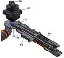
도 2는 본 발명에 따른 내시경의 일 실시예를 도시한 분해 사시도이다.
도 3은 도 2에 도시된 실시예 중 핸들부 및 프로브부의 결합부를 확대하여 도시한 분해 사시도이다.
도 4는 도 2에 도시된 실시예 중 프로브부의 결합부를 확대하여 도시한 사시도이다.
도 5는 도 2에 도시된 실시예 중 핸들부의 내부 구조를 도시한 사시도이다.
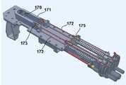
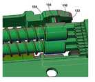
도 6은 도 2에 도시된 실시예 중 핸들부와 프로브부의 결합부의 내부 구조를 확대하여 도시한 분해 사시도이다.
도 7은 도 2에 도시된 실시예에서 프로브부의 내부 중 일부를 도시한 평면도이다.
도 8은 도 7 중 일부를 확대하여 도시한 평면도이다.
도 9는 도 7 중 제2 커넥터와 피니언 기어를 도시한 사시도이다.
도 10은 도 2에 도시된 실시예 중 핸들부의 내부를 도시한 사이도이다.
도 11은 도 2에 도시된 실시예 중 핸들부의 내부를 도시한 부분 절개도이다.
도 12는 도 2에 도시된 실시예에서 핸들부와 프로브부가 결합된 상태를 도시한 평면도이다.
도 13은 도 2에 도시된 실시예에서 핸들부와 프로브부가 결합된 상태를 도시한 측면도이다.
도 14는 도 2에 도시된 실시예 중 스토퍼를 확대하여 도시한 사시도이다.
도 15는 도 2에 도시된 실시예 중 프로브부의 단부를 확대하여 도시한 사시도이다.1 is a cross-sectional view schematically showing a conventional endoscope structure.
Figure 2 is an exploded perspective view showing an embodiment of the endoscope according to the present invention.
3 is an exploded perspective view illustrating an enlarged coupling part of a handle part and a probe part in the embodiment shown in FIG. 2;
4 is an enlarged perspective view illustrating a coupling part of a probe unit in the embodiment illustrated in FIG. 2.
5 is a perspective view illustrating an internal structure of a handle part of the embodiment illustrated in FIG. 2.
6 is an exploded perspective view illustrating an enlarged internal structure of a coupling part of a handle part and a probe part of the embodiment illustrated in FIG. 2.
FIG. 7 is a plan view illustrating a part of the inside of the probe unit in the embodiment illustrated in FIG. 2.
8 is an enlarged plan view of a portion of FIG. 7.
9 is a perspective view illustrating the second connector and the pinion gear in FIG. 7.
FIG. 10 is a diagram illustrating an interior of a handle part of the embodiment illustrated in FIG. 2.
FIG. 11 is a partial cutaway view illustrating the inside of a handle part of the embodiment illustrated in FIG. 2.
FIG. 12 is a plan view illustrating a state in which a handle part and a probe part are coupled in the embodiment shown in FIG. 2.
FIG. 13 is a side view illustrating a state in which a handle part and a probe part are coupled in the embodiment shown in FIG. 2.
FIG. 14 is an enlarged perspective view of the stopper of the embodiment illustrated in FIG. 2.
FIG. 15 is an enlarged perspective view of an end portion of the probe unit of the embodiment illustrated in FIG. 2.
이하에서는, 첨부된 도면을 참조하여 본 발명에 따른 착탈 가능한 프로브를 구비한 내시경의 실시예에 대해서 상세하게 설명하도록 한다.Hereinafter, with reference to the accompanying drawings will be described in detail an embodiment of the endoscope having a removable probe according to the present invention.
도 2를 참조하면, 본 발명에 따른 착탈 가능한 프로브를 구비한 내시경의 일 실시예가 도시되어 있다. 상기 실시예는 크게 핸들부(100)와 상기 핸들부(100)에 착탈 가능하게 장착되는 프로브부(200)를 포함한다. 이외에도 상기 실시예는 외부의 장치와 연결되기 위한 커넥터 어댑터(50)를 포함하고, 상기 커넥터 어댑터(50)는 유니버셜 코드(60)에 의해 상기 핸들부(100)와 연결된다. 여기서, 상기 커넥터 어댑터(50) 및 상기 유니버셜 코드(60)는 예시적인 것으로서 반드시 도시된 형태에 한정되는 것은 아니며 내시경에 적용될 수 있는 임의의 것을 채용할 수 있음은 물론이다.2, an embodiment of an endoscope with a removable probe according to the present invention is shown. The embodiment includes a
상기 핸들부(100)는 시술자가 파지하기 위한 파지공간을 제공하면서 내부에 상기 프로브부를 구동하기 위한 체인 및 케이블 등이 수납되는 바디부(110)를 포함한다. 도 3을 참조하면, 상기 바디부(110)의 일측단부에는 핸들측 결합부(120)가 제공된다. 상기 핸들측 결합부(120)는 상기 핸들부(100)의 단부를 폐쇄하는 엔드 커버(121)를 구비한다. 상기 엔드 커버(121)는 도 2를 기준으로 하부에 시술시 환부에 저공되는 공기 및 물을 제공하기 위한 두 개의 공급채널(122)과 이들의 사이에 석션 채널(123)이 형성된다. 상기 공기 공급채널, 물 공급채널 및 석션 채널은 대략 원통 형상을 가지며, 내부는 비어 있어 상기 프로브부와 결합시에 프로브부의 내부로 삽입되어 물이나 공기 등이 누설되지 않고 안정적으로 시술 또는 피검 부위에 공급될 수 있도록 한다.The
상기 채널들의 상측에는 연결 터미널(124)이 구비된다. 상기 연결 터미널(124)는 상기 프로브부의 단부에 구비되는 카메라 등에 의해 얻어진 데이터가 외부 기기로 전달될 수 있도록 프로브부와 전기적으로 연결되도록 구비되는 것으로서, 일예로 상기 연결 터미널(124)은 음성 및 영상을 전송하기 위한 HDMI 단자일 수 있다.
상기 채널과 연결 터미널의 사이에는 복수 개의 관통공(125)이 형성되는데, 상기 관통공들은 상기 프로브부에 구비되는 제2 커넥터 및 스토퍼 해제구 등이 상기 핸들부의 내부로 삽입될 수 있도록 하는 통로 역할을 하게 된다.A plurality of through
상기 결합부(120)는 상기 바디부(110)에 비해서 작은 직경을 갖도록 형성되고, 그 외주부에는 공기 또는 물 등이 누설되지 않도록 하는 오링(126)이 구비될 수 있다.The
도 2로 돌아가서, 상기 바디부(110)의 일측 상부에는 제1 및 제2 노브(111, 112)가 도 2를 기준으로 상하 방향을 따라서 적층된 형태로 구비된다. 상기 제1 및 제2 노브(111, 112)는 후술할 제1 및 제2 스프라켓과 각각 연결되며, 서로 독립적으로 회전할 수 있도록 구성된다. 상기 각각의 노브들은 시술자가 용이하게 파지하고 회전시킬 수 있도록 복수 개의 이가 돌출된 형태를 갖는다.2, the first and
한편, 제1 노브는 제2 노브가 정지된 상태를 유지한 채로 독립적으로 회전할 수 있다. 마찬가지로 제2 노브는 제1 노브가 정지된 상태를 유지한 채로 독립적으로 회전할 수 있다. 상기 제1 노브(111)는 상기 프로브부의 상하 이동을 제어한다. 즉, 제1 노브를 시계 또는 반시계 방향으로 돌리면, 그에 따라 프로브부의 단부가 상향 또는 하향으로 휘어지게 된다. 상기 제2 노브(112)는 상기 프로브부의 좌우 이동을 제어한다. 즉, 제2 노브(112)를 시계 또는 반시계 방향으로 돌리면, 그에 따라 프로브부의 단부가 좌측 또는 우측으로 휘어지게 된다.On the other hand, the first knob can be rotated independently while the second knob is stopped. Similarly, the second knob can be rotated independently while the first knob remains stationary. The
이렇게 제1 및 제2 노브(111, 112)의 조작을 통래서 프로브부의 회전 방향을 임의로 조절할 수 있게 된다. 경우에 따라서는 프로브부가 특정의 각도로 휘어진 상태를 고정해야 할 필요가 있을 수 있으며, 이를 위해서 상기 제2 노브(112)의 상측에 고정 노브(113)가 구비된다. 상기 고정 노브(113)를 회전시키면, 상기 제1 및 제2 스프라켓이 회전되지 않도록 고정되고, 이에 따라 프로브부의 단부도 고정된 상태를 유지하게 된다.Thus, the direction of rotation of the probe unit can be arbitrarily adjusted through the manipulation of the first and
상기 프로브부(200)는 인체 내부로 삽입되기 위한 프로브(210)가 일측에 구비되고, 타측에는 상기 핸들부(100)와 결합되기 위한 결합부(220)를 구비한다. 상기 프로브(210)에는 카메라 등이 설치될 수 있으며, 후술할 와이어의 이동에 의해서 상하좌우로 휘어질 수 있도록 유연성 재질로 이루어진다. 상기 프로부를 이동시키는 수단은 통상의 것을 채용할 수 있으므로, 본 명세서에서는 그 상세에 대한 설명은 생략하기로 한다.The
상기 프로브부(200)에 구비되는 결합부(220)에는 상기 핸들부와의 고정을 위한 고정 너트(201)를 포함한다. 상기 고정 너트(201)는 상기 프로브부의 단부 일부와 핸들부의 단부 일부, 구체적으로는 각각에 구비되는 결합부들의 외주부를 동시에 둘러싸도록 구성된다. 아울러, 상기 고정 너트(201)는 상기 프로브부(200)에 대해서 소정 각도범위에서 회전할 수 있도록 장착되며, 회전 방향에 따라서 헨들부와 체결되거나 분리될 수 있다. 즉, 두 개의 결합부들이 서로 결합된 상태에서 상기 고정 너트(201)를 일방향으로 회전 시키면 핸들부는 고정 너트와 체결되면서 결합된 상태를 유지하게 되며, 고정 너트(201)를 반대 방향으로 회전시키면 상기 핸들부(100)와 상기 고정 너트(201)와의 결합이 해제되면서, 핸들부는 프로브부로부터 분리된 수 있는 상태에 있게 된다.The
도 4는 상기 프로브부(200)측 결합부(220)를 도시한 것으로서, 도 4를 참조하면, 상기 결합부(220)는 프로브부의 일측 단부를 폐쇄하는 엔드 커버(221)가 구비된다. 상기 엔드 커버(221)에는 상술한 공급 채널(122)과 석션 채널(123)이 삽입되는 3개의 채널 수용관(222)이 형성된다. 상기 각각의 채널 수용관(222) 내부가 비어있는 원통형의 형태를 가지며, 삽입될 각각의 채널의 외경에 대응되는 내경을 갖도록 형성된다. 그리고, 공급되는 물 또는 공기 등의 누설을 방지하기 위한 오링이 내부에 구비될 수 있다.4 illustrates the
상기 채널 수용관(222)의 반대측에는 상기 연결 터미널에 대응되는 또 다른 연결 터미널(223)이 구비된다. 즉, 상기 핸들부에는 수 터미널이 구비되는 것이고, 상기 프로브부에는 암 터미널이 구비되는 것이나. 그 역도 가능한다.The other side of the
상기 채널 수용관(222)과 상기 연결 터미널(223)의 사이에는 4개의 제2 커넥터의 단부 및 스토퍼 해제구가 각각 돌출되어 배치된다. 이들에 대해서는 후술한다.End portions of the four second connectors and the stopper release ports are respectively protruded between the
이제 도 5를 참조하여, 상기 핸들부(100)의 내부 구조에 대해서 설명한다. 도 5를 참조하면, 상기 핸들부(100)의 연결 터미널(120)와 인접하여 PCB(124a)가 배치된다. 상기 PCB(124a)는 상기 연결 터미널(124)과 전기적으로 연결되며, 연결 터미널의 동작을 제어한다. Now, with reference to FIG. 5, the internal structure of the
그리고, 상기 엔드 커버(121)와 인접하여 4개의 제1 커넥터(130)들이 배치된다. 상기 4개의 제1 커넥터(130)는 내부가 비어있는 중공관의 형태를 가지며, 정면에서 보았을 때 사각형을 이루도록 배치된다. 상기 제1 커넥터(130)의 노브측 단부에는 커넥터 가이드 플레이트(140)가 배치된다. 상기 커넥터 가이드 플레이트(140)는 상기 4개의 제1 커넥터(130)가 삽입되는 가이드 홀(미도시)을 포함하며, 상기 제1 커넥터(130) 각각은 상기 가이드 홀의 내부에서 슬라이드 가능하게 장착된다. 즉, 상기 커넥터 가이드 플레이트(140)는 상기 제1 커넥터들을 고정할 뿐만 아니라 슬라이드 이동을 가이드하는 역할을 겸하고 있다.In addition, four
그리고, 상기 제1 커넥터(130)의 외주부에는 리턴 스프링(132)이 장착되어, 외력이 작용하지 않는 경우 상기 제1 커넥터(130)들을 도 5에 도시된 위치로 복귀시키는 탄성력을 가하게 된다. 동작 중에, 상기 제1 및 제2 노브에 의해 상기 제1 커넥터(130)들이 도 5에 도시된 위치로부터 노브측으로 슬라이드 이동하게 되나, 노브에 가해지는 힘이 제거되면 상기 리턴 스프링에 의해서 제1 커넥터들이 도 5에 도시된 위치로 복귀하게 되는 것이다.In addition, a
여기서, 도 5를 기준으로 하부에 배치되는 두 개의 제1 커넥터는 제1 노브(111)의 동작에 연동된다. 즉, 제1 노브(111)가 회전되면 상기 하측의 제1 커넥터들이 이동하면서 프로브를 상하로 회전시키는 것이다. 아울러, 상부에 배치되는 두 개의 제1 커넥터는 제2 노브(112)의 동작에 연동되어, 제2 노브(112)가 회전되면 상측의 제1 커넥터들이 이동하면서 프로브를 좌우로 회전시키게 된다.Here, the two first connectors disposed at the lower side with reference to FIG. 5 are linked to the operation of the
상기 제1 커넥터(130)들의 좌우측으로 각각 하나의 스토퍼(150)가 배치된다. 상기 스토퍼(150)는 상기 제1 커넥터의 길이방향으로 연장되는 아암(152)을 가지며, 상기 아암(152)은 그 일측 단부가 상기 커넥터 가이드 플레이트(140)에 고정된다. 따라서, 상기 스토퍼(150)는 상기 커넥터 가이드 플레이트(140)와의 고정점을 기준으로 좌우로 소정 각도만큼 회전할 수 있으나, 외력이 가해지지 않은 경우에는 도 5에 도시된 바와 같이 상기 제1 커넥터(130)와 인접한 위치에 놓이게 된다. 상기 스토퍼의 동작에 대해서는 후술한다.One
상기 제1 커넥터(130)들의 하부에는 상기 공급채널(122) 및 석션채널(124)과 연결되는 공급관(154)이 배치된다. 상기 공급관은 상기 내시경의 외부와 연결되어 물과 공기 등을 상기 공급채널(122)에 공급하거나 석션채널(124)을 통해 흡입하게 된다.A
상기 커넥터 가이드 플레이트(130)의 좌측 하부에는 베이스 플레이트(160)가 배치된다. 상기 베이스 플레이트(160)는 상기 핸들부(100)의 내부에 구비되는 각종 부품들을 지지하는 지지부로서 기능하며, 얇은 판재의 형태를 갖고 있다. 상기 베이스 플레이트(160)의 상부에는 후술할 스프라켓 및 체인 등이 배치되고, 이들의 상부에 보호 플레이트(162)가 배치된다. 상기 베이스 플레이트(160)와 상기 보호 플레이트(162)가 협력하여 내부 공간을 형성하고, 형성된 공간은 후술할 체인 및 엔드 와이어가 이동하는 공간으로서 사용된다.The
도 6을 참조하면, 상기 핸들부(100)의 내부 구조와 프로브부(200)의 내부 구조가 함께 도시되어 있다. 도 6을 참조하면, 상기 제1 커넥터(130)의 프로브부측 단부에는 엔드 팁(133)이 구비되어 있다. 상기 엔드 팁(133)은 제1 커넥터(130)의 다른 부분에 비해서 확장된 직경을 가지고 있고, 그 단부는 개방되어 삽입구(133a)를 형성하고 있다. 상기 삽입구(133a)는 일측으로 연장된 장공의 형태를 갖는다. 그리고, 상기 개방된 단부와 인접하여 좌우에 각각 절개부(133b)가 형성된다. 이로 인해서, 상기 절개부(133b)와 개방 단부 사이에 단턱부가 형성되게 된다. 아울러, 상기 엔드 팁(133)의 측면에는 가이드 핀(134)이 형성되는데, 이는 후술할 가이드 홈에 끼워져서 제1 커넥터의 슬라이드 이동시에 제1 커넥터가 그 길이방향 축을 중심으로 자전하면서 슬라이드하도록 한다.Referring to FIG. 6, the internal structure of the
한편, 상기 프로브부(200)의 결합부(220)에 배치되는 연결 터미널(223)은 핸들부에서와 동일하게 PCB(224)와 전기적으로 연결된다. 그리고, 상기 PCB(224)의 하부에 4개의 제2 커넥터(230)가 배치된다.Meanwhile, the
상기 4개의 제2 커넥터(230)는 프로브부가 핸들부와 결합된 경우 상술한 제1 커넥터의 내부로 각각 삽입된다. 구체적으로, 상기 제2 커넥터(230)의 핸들부측 단부에는 대략 원추형의 삽입돌기(232)가 형성되어 있고, 상기 삽입돌기(232)는 상술한 제1 커넥터의 엔드 팁(133)에 형성되는 삽입구(133a)의 내부에 삽입될 수 있는 크기 및 형태를 갖는다. 상기 삽입돌기(232)의 단부는 다른 부분에 비해 폭이 확장된 형태를 가지며, 이는 상술한 제1 커넥터의 엔드 팁에 형성되는 단턱부와 맞물려서 제1 커넥터와 제2 커넥터가 서로 연동될 수 있도록 기능하게 된다. 이에 대해서는 후술한다.The four
아울러, 상기 제2 커넥터의 좌우측에 각각 하나의 스터퍼 해제구(240)가 배치된다. 상기 스토퍼 해제구(240)는 단부가 테이퍼 면을 갖도록 형성되며, 길이 방향을 따라서 연장된 형태를 갖는다. 그리고, 상기 스토퍼 해제구(240)는 상기 프로브부가 핸들부에 장착되었을 때, 상기 핸들부의 단부에 배치되는 엔드 커버를 관통하여 상기 스토퍼(150)의 내측으로 삽입될 수 있을 정도의 길이를 갖는다. 상기 스토퍼 해제구가 상기 스토퍼의 내측으로 삽입되면, 스토퍼는 제1 커넥터로부터 멀어지는 방향으로 이동하게 되고, 그 결과 스토퍼와 제1 커넥터의 결합이 해제된다. 이에 대해서는 후술한다.In addition, one stuffer release opening 240 is disposed at left and right sides of the second connector. The stopper release opening 240 is formed to have a tapered surface at an end thereof, and has a shape extending in the longitudinal direction. When the probe part is mounted on the handle part, the stopper release opening 240 has a length enough to be inserted into the
한편, 상기 제2 커넥터(230)의 측면에는 랙 기어부(233)가 형성된다. 도 7 내지 도 9를 참조하면, 상기 랙 기어부(233)는 마주하는 한 쌍의 제2 커넥터가 서로 대향하는 면에 형성된다. 즉, 하부에 배치되며 프로브의 상하 이동을 담당하는 한 쌍의 제2 커넥터가 대향하는 명과, 상부에 배치되며 프로브의 좌우 이동을 담당하는 한 쌍의 제2 커넥터가 대향하는 면에 각각 형성된다.Meanwhile, a
상기 각각의 랙 기어와 각각 기어 결합되는 피니언 기어(250)가 추가로 구비된다. 상기 피니언 기어(250)는 2개가 도 6을 기준으로 상하로 이격되어 배치된다. 하부에 배치되는 피니언 기어(250)는 프로브의 상하 이동을 담당하는 한 쌍의 제2 커넥터에 형성되는 랙 기어부와 맞물리고, 상부에 배치되는 피니언 기어(250)는 프로브의 좌우 이동을 담당하는 한 쌍의 제2 커넥터에 형성되는 랙 기어부와 맞물린다.Pinion gears 250 geared to the respective rack gears are further provided. Two pinion gears 250 are disposed spaced apart from each other vertically based on FIG. 6. The
상기 피니언 기어(250)는 상기 제2 커넥터의 길이방향과 직교하게 배치되는 회전축(252)을 중심으로 회전하도록 설치되며, 상기 회전축(252)은 제2 커넥터의 하측에 배치되는 회전축 지지 플레이트(254)에 회전 가능하게 장착된다. 그리고, 상기 제2 커넥터(230)의 타측 단부에는 상기 프로브를 이동시키는 와이어(260)가 장착된다. 여기서, 상기 와이어(260)는 단순히 상기 제2 커넥터에 체결되는 것이 아니라, 일정 거리만큼 제2 커넥터의 내부로 수납될 수 있도록 장착될 수 있다. 즉, 도 8에 도시된 바와 같이 상기 와이어(260)는 와이어 고정편(262)을 통해 제2 커넥터와 연결되는데, 상기 와이어 고정편(262)은 그 단부에 형성된 단턱부가 제2 커넥터에 접촉할 때까지 상기 제2 커넥터의 내부로 삽입될 수 있다.The
다시 말해서, 상기 와이어 고정편(262)은 소정 거리 내에서는 상기 제2 커넥터에 대해서 슬라이드 이동이 가능하지만, 상기 범위를 초과하면 상기 제2 커넥터와 함께 이동하게 된다. 이러한 슬라이드 이동 거리는 회전 구동시에 반경 방향 내측에 위치한 와이어와 외측에 위치한 와이어의 이동 거리의 차이를 보상할 수 있다.In other words, the
상기 피니언 기어(250)에 의해서 대향하는 한 쌍의 제2 커넥터는 서로 반대 방향으로 이동하게 된다. 여기서, 설명의 편의를 위해서 상기 제2 커넥터가 상기 핸들부측으로 이동하는 방향을 수축 방향, 핸들부로부터 멀어지도록 이동하는 방향을 이완 방향으로 지칭한다. 상기 핸들부에 프로브부가 결합된 상태에서 외력이 가해지지 않은 상황, 즉 상기 제1 또는 제2 노브를 조작하지 않은 상황에서 제2 커넥터는 도 7에 도시된 위치로 정렬된다. 만일, 제1 또는 제2 노브를 회전하면 해당 노브와 연결되는 제1 커넥터 중 하나가 수축 방향으로 이동하게 된다. 이 때, 다른 하나의 제1 커넥터는 이완 방향으로 이동하는 것이 아니라 외력이 가해지지 않은 상태에서의 위치(이하, '중립 위치'라 지칭한다)를 유지하게 된다.The pair of second connectors facing each other by the
이때, 수축 방향으로 이동하는 제1 커넥터와 연동되는 제2 커넥터는 제1 커넥터에 의해서 수축 방향으로 이동하게 된다. 이러한 제2 커넥터의 움직임은 상기 랙 기어부 및 피니언 기어(250)에 의해 맞물린 다른 하나의 제2 커넥터를 이완 방향으로 이동시키게 된다. 즉, 수축 방향의 이동에 있어서는 제1 및 제2 커넥터가 연동되어 함께 이동하지만, 이완 방향의 이동에 있어서는 제1 커넥터는 중립 위치를 유지하고 제2 커넥터만이 이완 방향으로 이동하게 된다. 이로 인해서, 이완 방향에서의 제1 및 제2 커넥터는 서로 분리되게 된다.At this time, the second connector interlocked with the first connector moving in the contraction direction is moved in the contraction direction by the first connector. The movement of the second connector causes the other second connector engaged by the rack gear part and the
따라서, 프로브는 제2 커넥터 중 어느 한쪽의 힘만이 아니라 수축 및 이완 방향 모두의 경우에 있어서 외력을 받게 되고, 그에 따라 보다 정확하고 직접적인 조작감을 얻을 수 있게 된다. 아울러, 반경의 차이로 인해서 수축 방향에 위치한 와이어의 이동 길이는 이완 방향에 위치한 와이어의 이동 길이보다 작기 때문에 이러한 이동 거리의 차이를 흡수할 필요가 있다. 상술한 실시예에서 이완 방향에 있어서는 제1 및 제2 커넥터가 분리되기 때문에 제2 커넥터는 제1 커넥터에 의해 구속되지 않고 자유롭게 이동할 수 있어, 상기와 같은 이동 거리의 차이를 원활하게 흡수할 수 있게 된다. 아울러, 상술한 바와 같이 상기 제2 커넥터(230)와 와이어(260) 사이의 슬라이드 결합도 상기와 같은 이동 거리의 차이를 흡수하는 버퍼로서 기능하게 된다.Therefore, the probe is subjected to external force not only in the force of either of the second connectors but also in both the contracting and the relaxation directions, whereby a more accurate and direct feeling of operation can be obtained. In addition, because of the difference in radius, the movement length of the wire located in the contraction direction is smaller than the movement length of the wire located in the relaxation direction, so it is necessary to absorb the difference in the movement distance. In the above-described embodiment, since the first and second connectors are separated in the relaxation direction, the second connector can move freely without being restrained by the first connector, so that the difference in the movement distance can be smoothly absorbed. do. In addition, as described above, the slide coupling between the
도 10 및 도 11은 상기 핸들부의 내부 구조를 도시한 사시도로서, 도 10 및 11을 참조하면, 상기 제1 및 제2 노브(111, 112)의 하부에는 두 개의 스프라켓(170)이 상기 제1 및 제2 노브의 회전에 연동하여 회전 가능하게 장착된다. 그리고, 상기 각각의 스프라켓과 맞물려 이동하는 체인(171)이 구비된다. 상기 체인(171)은 양단부가 각각 엔드 와이어(172)에 결합되되, 이들 사이에는 와이어 결합구(173)가 구비된다. 상기 와이어 결합구(173)는 인접하여 배치되는 체인 가이드(174)와 접촉하면서 이동이 가이드된다.10 and 11 are perspective views illustrating an internal structure of the handle part. Referring to FIGS. 10 and 11, two
상기 체인 가이드(174)는 내부가 비어있는 직육면체의 형태를 가지며, 그 측면이 상기 와이어 결합구(173)와 접촉하면서 가이드 면으로서 기능하게 된다. 이로 인해, 상기 체인은 수축 또는 이완 방향으로 이동하더라도 상기 체인 가이드(174)에 의해 안정적으로 이동할 수 있게 된다.The
상기 엔드 와이어(172)는 상기 제1 커넥터(130)와 결합된다. 구체적으로, 도 11에 도시된 바와 같이, 상기 엔드 와이어(172)는 상기 제2 커넥터에와와 마찬가지로 제1 커넥터(130)와 와이어 고정편(175)에 의해 결합된다. 상기 와이어 고정편(175)은 상기 제1 커넥터(130)의 단부에 형성된 삽입홀 내에 제한된 범위 내에서 슬라이드 가능하게 장착된다. 여기서, 상기 슬라이드 이동과 관련하여, 수축 방향으로 이동하는 경우에는 슬라이드 이동이 없이 즉시 와이어 고정편과 제1 커넥터가 함께 이동하도록 하고, 이완 방향으로 이동하는 경우에만 슬라이드될 수 있도록 구성할 수 있다.The
상기 한 쌍의 체인은 각각 프로브의 상하 이동과 좌우 이동을 담당하며, 이들은 서로 독립적으로 이동할 수 있다. 그리고, 상기 체인이 스프라켓의 회전에 의해 이동할 경우 수축 방향에 위치한 제1 커넥터는 수축 방향으로 이동하지만, 이완 방향에 위치한 제1 커넥터는 상술한 와이어 고정편의 결합 구조로 인해서 이완 방향으로 이동하지 않고 중립 위치를 유지하게 된다.The pair of chains are respectively responsible for vertical movement and horizontal movement of the probe, and they can move independently of each other. In addition, when the chain is moved by the rotation of the sprocket, the first connector located in the contraction direction moves in the contraction direction, but the first connector located in the relaxed direction does not move in the relaxed direction due to the coupling structure of the wire fixing piece described above. Will maintain its position.
상기 제1 커넥터들은 커넥터 하우징((180) 내에 수용된다. 상기 커넥터 하우징(180)은 직육면체의 형태를 가지며, 내부에는 상기 제1 커넥터(130) 들이 슬라이드 가능하게 수납될 수 있는 공간을 갖는다. 또한, 상기 커넥터 하우징(180)에는 상기 엔드 팁(133)에 형성되는 가이드 핀(134)과 맞물리는 가이드 홈(182)이 형성되어 있다.The first connectors are accommodated in the
상기 가이드 홈(182)은 상기 커넥터 하우징(180)의 측면에서 시작하여 길이 방향을 따라 진행하면서 커넥터 하우징(180)의 상부면으로 이동한다. 즉, 상기 가이드 홈(182)의 시작점은 커넥터 하우징의 측면에 있지만 종료 지점은 상부면에 배치된다. 이로 인해서, 상기 제1 커넥터는 상기 가이드 핀(134)과 상기 가이드 홈(182)에 의해서 수축 방향으로 이동하면서 약 90도 정도 자전하게 된다.The
중립 위치에서, 상기 제2 커넥터(230)의 삽입돌기(232)는 엔드 팁(133)에 형성된 삽입구(133a)에 삽입되어 있지만 제1 및 제2 커넥터는 서로 연동되지는 않는다. 제1 커넥터가 이동하더라도 삽입돌기(232)가 상기 삽입구(133a)로부터 손쉽게 이탈할 수 있기 때문이다. 따라서, 상기 핸들부와 프로브부를 결합 또는 분리할 때 각각에 구비된 와이어들을 연결하기 위한 별도의 조작을 필요로 하지 않는다.In the neutral position, the
결합 후 제1 또는 제2 노브를 회전시키면 이에 연동된 제1 커넥터 중 하나는 수축 방향으로 이동하게 된다. 그러나, 상기 가이드 핀(134) 및 가이드 홈(182)에 의해 제1 커넥터(130)는 90도 정도 자전하면서 이동하게 되고, 그에 따라 상기 삽입돌기(232)의 배면이 상기 엔드 팁(133)에 형성되는 절개부(133b) 외부로 돌출되어 단턱부에 걸리게 된다. 이로 인해서, 제1 커넥터가 수축 방향으로 이동하면 제2 커넥터도 함께 이동하게 되며, 결과적으로 프로브가 회전한다.When the first or second knob is rotated after engagement, one of the first connectors linked thereto moves in the contracting direction. However, the
외력을 제거하면, 상기 리턴 스프링에 의해서 제1 커넥터는 중립 위치로 복귀하고 가이드 핀 및 가이드 홈에 의해 다시 역방향으로 90도 자전하면서 삽입돌기는 상기 삽입구로부터 빠져나올 수 있는 상태에 놓이게 된다. 결과적으로, 핸들부와 프로브부를 체결 또는 분리함에 있어서 와이어를 서로 연결하거나 분리하기 위한 별도의 작업이 필요업게 되므로, 매우 용이하게 핸들부와 프로브부를 탈부착할수 있게 된다.Upon removal of the external force, the return spring returns the first connector to the neutral position and rotates 90 degrees back in the reverse direction by the guide pin and the guide groove, thereby placing the insertion protrusion in the state of being able to escape from the insertion hole. As a result, in the fastening or detachment of the handle portion and the probe portion, a separate operation for connecting or disconnecting the wires is required, so that the handle portion and the probe portion can be easily detached.
핸들부가 분리된 상태에서 제1 및 제2 노브가 조작되면 제1 커넥터가 이동하면서 파손의 우려가 있을 수 있으므로 이를 차단할 필요가 있을 수 있다. 도 14를 참조하면, 상술한 스토퍼(150)는 내측면에 가이드 핀 수용홈(156)을 갖는다. 상기 가이드 핀 수용홈(156)은 도 13에 도시된 바와 같이 서로 인접하여 배치되는 두 개의 가이드 핀(134)이 내부에 수용될 수 있을 정도의 깊이 및 폭을 갖는다. 상기 가이드 핀 수용홈(156)의 길이는 중립 위치에서 두 개의 가이드 핀을 모두 수용할 수 있을 정도로 형성된다. 경우에 따라서는, 상기 가이드 핀을 각각 수용하는 복수 개의 수용홈을 형성할 수도 있다.When the first and second knobs are operated in a state in which the handle part is separated, it may be necessary to block the first connector because it may be damaged while moving. Referring to FIG. 14, the
이렇게 상기 가이드 핀이 가이드 핀 수용홈 내에 수용되면, 수용홈의 내벽에 의해 가이드 핀의 이동이 저지된다. 따라서, 제1 및 제2 노브를 회전하려 해도, 가이드 핀이 수용홈에 막혀 이동되지 않으므로 노브의 회전도 불가능하게 된다. 이는 상기 핸들부가 프로브부로부터 분리된 경우이나, 프로브부가 핸들부에 결합되면, 상술한 스토퍼 해제구(240)가 상기 스토퍼(150)와 가이드 핀(232)의 사이로 삽입되면서 스토퍼에 형성된 수용홈(156)으로부터 가이드 핀이 분리되게 된다. 또한, 상기 스토퍼 해제구(240)는 프로브부가 핸들부에 결합된 상태에서는 상시 스토퍼의 내측에 배치되므로 가이드 핀이 수용홈에 재결합되는 것을 방지하게 된다.When the guide pin is accommodated in the guide pin receiving groove in this way, the movement of the guide pin is prevented by the inner wall of the receiving groove. Accordingly, even when the first and second knobs are to be rotated, the guide pins are not blocked by the receiving grooves and therefore cannot be rotated. This is when the handle portion is separated from the probe portion, or when the probe portion is coupled to the handle portion, the above-mentioned stopper release opening 240 is inserted between the
따라서, 상기 노브는 핸들부가 프로브부에 결합된 상태에서만 조작이 가능해지므로, 핸들부와 프로브부가 분리된 상태에서 의도치 않은 조작에 의해 기기가 파손되는 일을 방지할 수 있게 된다.Therefore, since the knob can be operated only when the handle part is coupled to the probe part, the knob can be prevented from being damaged by an unintentional operation while the handle part and the probe part are separated.
도 15를 참조하면, 상기 프로브부(200)의 단부에는 단부 커버(280)가 구비된다. 상기 단부 커버(280)는 납짝한 원통형 구조를 가지며, 프로브부(200)의 단부게 결합된다. 그리고, 상기 단부 커버(280)에는 피검부에 대한 영상을 획득하기 위한 이미지 센서(282)와 공기 및 물을 분사하기 위한 노즐 파이프(284)가 각각 장착된다. 또한, 상기 단부 커버(280)에는 복수 지점에 투광창(286)이 구비된다. 상기 투광창(286)은 유리 또는 투명 재질의 판재로 이루어지며, 후술할 조명부로부터 조사된 빛을 외부로 전달할 수 있는 구조를 갖는다.Referring to FIG. 15, an
상기 단부 커버(280)의 배면에 연성 PCB(290)가 배치되고, 상기 연성 PCB(290)에는 복수 개의 LED(292)가 장착된다. 상기 복수 개의 LED(292)는 상술한 투광창(286)과 대향하는 부분에 배치되어 피검부로 빛을 조사할 수 있도록 구성된다. 한편, 상기 연성 PCB에는 상술한 이미지 센서(282)도 장착된다. 복수 개의 LED를 조명부로서 활용하므로, 조도의 조절이 용이할 뿐만 아니라 조사되는 광량을 기존의 할로겐 램프 등에 비해 대폭적으로 증가시킬 수 있으므로 이미지 센서를 통해 얻어지는 이미지의 선명도를 더욱 향상시킬 수 있다.A
Claims (10)
Translated fromKorean상기 핸들부의 일측단부에 결합되며 내장된 와이어의 이동에 따라서 변형되는 프로브, 및 상기 프로부 내에 구비되어 상기 와이어의 양단에 각각 결합되는 복수 개의 제2 커넥터,를 포함하는 프로브부;
상기 핸들부와 상기 프로브를 착탈 가능하게 장착하는 고정수단; 및
상기 제1 커넥터의 수축 방향으로의 이동을 가이드하여 제1 커넥터를 회전시켜 제2 커넥터와 결합시키는 커넥터 체결 수단;을 포함하는 것을 특징으로 하는 내시경.A handle part including an adjustment knob, a sprocket rotated in connection with the adjustment knob, a chain reciprocally moved by the sprocket, and a plurality of first connectors installed to reciprocate in association with the chain;
A probe part coupled to one side end of the handle part, the probe part being deformed according to the movement of the embedded wire, and a plurality of second connectors provided in the pro part and respectively coupled to both ends of the wire;
Fixing means for detachably mounting the handle portion and the probe; And
And a connector fastening means for guiding the movement of the first connector in the contracting direction to rotate the first connector to engage with the second connector.
상기 체인의 양단에 각각 결합되는 엔드 와이어를 추가적으로 포함하고, 상기 엔드 와이어는 상기 제1 커넥터와 결합되어 제1 커넥터를 상기 스프라켓 측으로 당기는 것을 특징으로 하는 내시경.The method of claim 1,
And end wires respectively coupled to both ends of the chain, the end wires being coupled to the first connector to pull the first connector toward the sprocket.
상기 커넥터 체결수단은
상기 제1 커넥터의 단부에 구비되며, 삽입구 및 절개부를 갖는 엔드 팁; 및
상기 제2 커넥터의 단부에 구비되며 상기 삽입구 내부로 삽입되어 제1 커넥터의 회전에 따라 상기 절개부로 돌출되는 삽입돌기;를 포함하는 것을 특징으로 하는 내시경.The method of claim 1,
The connector fastening means
An end tip provided at an end of the first connector and having an insertion hole and an incision; And
And an insertion protrusion provided at an end of the second connector and inserted into the insertion hole and protruding into the cutout according to the rotation of the first connector.
상기 삽입돌기는 적어도 일부분의 폭이 다른 부분에 비해 확장되는 것을 특징으로 하는 내시경.The method of claim 3,
The insertion endoscope, characterized in that the width of at least one portion is extended compared to the other portion.
상기 삽입구는 장공 형태를 갖는 것을 특징으로 하는 내시경.The method of claim 3,
Endoscope characterized in that the insertion hole has a long hole shape.
상기 제1 커넥터와 엔드 와이어는 와이어 고정편을 개재하여 고정되고, 상기 와이어 고정편은 제한된 범위 내에서 상기 제1 커넥터에 대해서 상대 이동 가능하게 장착되는 것을 특징으로 하는 내시경.The method of claim 2,
And the first connector and the end wire are fixed through a wire fixing piece, and the wire fixing piece is mounted to be movable relative to the first connector within a limited range.
상기 제1 커넥터를 내부에 수용하며, 제1 커넥터의 이동을 가이드 하는 커넥터 하우징을 추가적으로 포함하는 것을 특징으로 하는 내시경.The method of claim 3,
An endoscope accommodating the first connector therein, and further comprising a connector housing for guiding the movement of the first connector.
상기 커넥터 하우징 내에서 연장되는 캠 홈과, 상기 캠 홈에 맞물리며 상기 엔드 팁에 형성되는 가이드 핀을 추가적으로 포함하고, 상기 가이드 핀이 상기 캠 홈을 따라 이동하면서 상기 제1 커넥터가 자전하는 것을 특징으로 하는 내시경.The method of claim 7, wherein
And a cam groove extending in the connector housing and a guide pin engaged with the cam groove and formed at the end tip, wherein the first connector rotates while the guide pin moves along the cam groove. Endoscope.
상기 가이드 핀을 수용하는 수용홈을 구비하여, 가이드 핀의 이동을 저지하는 스토퍼를 추가적으로 포함하는 것을 특징으로 하는 내시경.The method of claim 8,
An endoscope comprising a stopper for accommodating the guide pin and preventing the movement of the guide pin.
스토퍼 해제구가 상기 프로브부에 구비되고,
상기 스토퍼 해제구는 상기 프로브부가 상기 핸들부에 장착되는 경우에 스토퍼와 가이드 핀 사이에 개재하여 가이드 핀을 수용홈으로부터 이탈시키는 것을 특징으로 하는 내시경.The method of claim 9,
A stopper release port is provided in the probe unit,
The stopper release endoscope is characterized in that the guide pin is separated from the receiving groove via the stopper and the guide pin when the probe unit is mounted on the handle portion.
Priority Applications (6)
| Application Number | Priority Date | Filing Date | Title |
|---|---|---|---|
| KR1020180044870AKR102110352B1 (en) | 2018-04-18 | 2018-04-18 | Endoscope with a detachable probe |
| US16/970,816US11826022B2 (en) | 2018-04-18 | 2019-04-18 | Endoscope having separable probe |
| CN201980014290.6ACN111741706B (en) | 2018-04-18 | 2019-04-18 | Endoscope with separate probe |
| PCT/KR2019/004704WO2019203593A1 (en) | 2018-04-18 | 2019-04-18 | Endoscope having separable probe |
| DE112019002022.6TDE112019002022T5 (en) | 2018-04-18 | 2019-04-18 | Endoscope with a removable probe |
| JP2020544424AJP7049590B2 (en) | 2018-04-18 | 2019-04-18 | Endoscope with separate probe |
Applications Claiming Priority (1)
| Application Number | Priority Date | Filing Date | Title |
|---|---|---|---|
| KR1020180044870AKR102110352B1 (en) | 2018-04-18 | 2018-04-18 | Endoscope with a detachable probe |
Publications (2)
| Publication Number | Publication Date |
|---|---|
| KR20190121497Atrue KR20190121497A (en) | 2019-10-28 |
| KR102110352B1 KR102110352B1 (en) | 2020-06-08 |
Family
ID=68240263
Family Applications (1)
| Application Number | Title | Priority Date | Filing Date |
|---|---|---|---|
| KR1020180044870AActiveKR102110352B1 (en) | 2018-04-18 | 2018-04-18 | Endoscope with a detachable probe |
Country Status (6)
| Country | Link |
|---|---|
| US (1) | US11826022B2 (en) |
| JP (1) | JP7049590B2 (en) |
| KR (1) | KR102110352B1 (en) |
| CN (1) | CN111741706B (en) |
| DE (1) | DE112019002022T5 (en) |
| WO (1) | WO2019203593A1 (en) |
Cited By (2)
| Publication number | Priority date | Publication date | Assignee | Title |
|---|---|---|---|---|
| WO2022169262A1 (en)* | 2021-02-04 | 2022-08-11 | 주식회사 메디칼파크 | Disposable endoscope and disposable intubation apparatus having endoscope function |
| WO2023106747A1 (en)* | 2021-12-08 | 2023-06-15 | 주식회사 메디인테크 | Endoscope having power accommodation unit |
Families Citing this family (19)
| Publication number | Priority date | Publication date | Assignee | Title |
|---|---|---|---|---|
| WO2018098465A1 (en) | 2016-11-28 | 2018-05-31 | Inventio, Inc. | Endoscope with separable, disposable shaft |
| USD1018844S1 (en) | 2020-01-09 | 2024-03-19 | Adaptivendo Llc | Endoscope handle |
| US20220007918A1 (en)* | 2020-06-30 | 2022-01-13 | Pristine Surgical Llc | Endoscope with Bendable Camera Shaft |
| EP4171392A4 (en)* | 2020-06-30 | 2024-07-24 | Precision Robotics (Hong Kong) Limited | FLEXIBLE ENDOSCOPE WITH DETACHABLE HEAD AND HANDLE |
| CN112198656A (en)* | 2020-11-05 | 2021-01-08 | 徐州微普视光电科技有限公司 | An electric telescopic inspection endoscope |
| USD1051380S1 (en) | 2020-11-17 | 2024-11-12 | Adaptivendo Llc | Endoscope handle |
| DE102020134036A1 (en)* | 2020-12-17 | 2022-06-23 | Ambu A/S | Endoscope with an endoscope handle with a disconnect device |
| USD1031035S1 (en) | 2021-04-29 | 2024-06-11 | Adaptivendo Llc | Endoscope handle |
| USD1070082S1 (en) | 2021-04-29 | 2025-04-08 | Adaptivendo Llc | Endoscope handle |
| USD1066659S1 (en) | 2021-09-24 | 2025-03-11 | Adaptivendo Llc | Endoscope handle |
| KR102496047B1 (en)* | 2021-12-08 | 2023-02-07 | 주식회사 메디인테크 | Endoscope having Power Transmission Part |
| KR102720181B1 (en)* | 2022-01-14 | 2024-10-22 | (주) 태웅메디칼 | Detachable endoscope |
| KR102780174B1 (en)* | 2022-01-14 | 2025-03-14 | (주) 태웅메디칼 | Detachable endoscope for the duodenum |
| KR102769055B1 (en)* | 2022-01-14 | 2025-02-19 | (주) 태웅메디칼 | Detachable endoscope |
| CN114569040A (en)* | 2022-03-03 | 2022-06-03 | 上海秦隆医疗器械有限公司 | Endoscope device supporting disassembly and assembly |
| CN115054184B (en)* | 2022-06-15 | 2023-03-10 | 湖南省华芯医疗器械有限公司 | A reusable segment of endoscope handle, endoscope handle and endoscope |
| CN115120168A (en)* | 2022-08-31 | 2022-09-30 | 苏州科沁微视医疗器械有限公司 | Angle control device and endoscope |
| CN118892294A (en)* | 2023-05-05 | 2024-11-05 | 施长碧 | Endoscopic device and replaceable tube insertion mechanism and catheter used in combination |
| CN119867911B (en)* | 2025-01-15 | 2025-09-19 | 北京医院 | Resectoscope |
Citations (5)
| Publication number | Priority date | Publication date | Assignee | Title |
|---|---|---|---|---|
| KR20060122943A (en)* | 2004-03-02 | 2006-11-30 | 올림푸스 가부시키가이샤 | Endoscope |
| KR100912155B1 (en)* | 2004-07-02 | 2009-08-14 | 올림푸스 가부시키가이샤 | Endoscope |
| KR200461877Y1 (en)* | 2010-11-19 | 2012-08-13 | 주식회사 인트로메딕 | endoscope |
| JP5087035B2 (en)* | 2009-03-25 | 2012-11-28 | オリンパス株式会社 | Cover-type treatment endoscope and endoscope cover |
| KR20170100759A (en)* | 2016-02-26 | 2017-09-05 | 주식회사 현주인테크 | Divisible endoscope having a fastening structure |
Family Cites Families (14)
| Publication number | Priority date | Publication date | Assignee | Title |
|---|---|---|---|---|
| JP4370201B2 (en)* | 2004-05-14 | 2009-11-25 | オリンパス株式会社 | Endoscope |
| US7789826B2 (en)* | 2004-09-30 | 2010-09-07 | Boston Scientific Scimed, Inc. | Manually controlled endoscope |
| JP2007000427A (en) | 2005-06-24 | 2007-01-11 | Olympus Medical Systems Corp | Endoscope |
| KR100673413B1 (en)* | 2006-07-03 | 2007-01-24 | 주식회사 액츠비전 | Medical endoscopes with easy insertion |
| JP2009165722A (en) | 2008-01-18 | 2009-07-30 | Fujinon Corp | Endoscope |
| KR101092461B1 (en)* | 2009-06-23 | 2011-12-13 | 주식회사 케어텍 | Endoscope Refractor |
| KR101091999B1 (en)* | 2009-11-30 | 2011-12-08 | 주식회사 인트로메딕 | Insert device for endoscope, handle devices for endoscope, endoscope |
| KR20140063947A (en) | 2012-11-19 | 2014-05-28 | 삼성전자주식회사 | Separable type endoscope |
| EP2953521A4 (en) | 2013-02-08 | 2016-09-21 | Olympus Corp | Manipulator |
| KR101565958B1 (en)* | 2014-03-24 | 2015-11-05 | 가톨릭대학교 산학협력단 | Endoscope |
| CN206007355U (en)* | 2015-12-31 | 2017-03-15 | 凡梅迪克斯株式会社 | Endoscope-use scalpel |
| CN206007354U (en)* | 2016-02-01 | 2017-03-15 | 凡梅迪克斯株式会社 | Endoscope-use scalpel |
| KR20170100758A (en)* | 2016-02-26 | 2017-09-05 | 주식회사 현주인테크 | Wire connecting unit for divisible endoscope |
| CN106691361B (en)* | 2017-01-19 | 2020-10-23 | 深圳开立生物医疗科技股份有限公司 | Endoscope headstock and endoscope |
- 2018
- 2018-04-18KRKR1020180044870Apatent/KR102110352B1/enactiveActive
- 2019
- 2019-04-18JPJP2020544424Apatent/JP7049590B2/enactiveActive
- 2019-04-18WOPCT/KR2019/004704patent/WO2019203593A1/ennot_activeCeased
- 2019-04-18CNCN201980014290.6Apatent/CN111741706B/enactiveActive
- 2019-04-18DEDE112019002022.6Tpatent/DE112019002022T5/enactivePending
- 2019-04-18USUS16/970,816patent/US11826022B2/enactiveActive
Patent Citations (5)
| Publication number | Priority date | Publication date | Assignee | Title |
|---|---|---|---|---|
| KR20060122943A (en)* | 2004-03-02 | 2006-11-30 | 올림푸스 가부시키가이샤 | Endoscope |
| KR100912155B1 (en)* | 2004-07-02 | 2009-08-14 | 올림푸스 가부시키가이샤 | Endoscope |
| JP5087035B2 (en)* | 2009-03-25 | 2012-11-28 | オリンパス株式会社 | Cover-type treatment endoscope and endoscope cover |
| KR200461877Y1 (en)* | 2010-11-19 | 2012-08-13 | 주식회사 인트로메딕 | endoscope |
| KR20170100759A (en)* | 2016-02-26 | 2017-09-05 | 주식회사 현주인테크 | Divisible endoscope having a fastening structure |
Cited By (3)
| Publication number | Priority date | Publication date | Assignee | Title |
|---|---|---|---|---|
| WO2022169262A1 (en)* | 2021-02-04 | 2022-08-11 | 주식회사 메디칼파크 | Disposable endoscope and disposable intubation apparatus having endoscope function |
| WO2023106747A1 (en)* | 2021-12-08 | 2023-06-15 | 주식회사 메디인테크 | Endoscope having power accommodation unit |
| US12226073B2 (en) | 2021-12-08 | 2025-02-18 | Medintech Inc. | Endoscope having power accommodation unit |
Also Published As
| Publication number | Publication date |
|---|---|
| CN111741706A (en) | 2020-10-02 |
| WO2019203593A1 (en) | 2019-10-24 |
| JP7049590B2 (en) | 2022-04-07 |
| US20210113068A1 (en) | 2021-04-22 |
| CN111741706B (en) | 2023-10-20 |
| US11826022B2 (en) | 2023-11-28 |
| KR102110352B1 (en) | 2020-06-08 |
| DE112019002022T5 (en) | 2021-01-07 |
| JP2021514717A (en) | 2021-06-17 |
Similar Documents
| Publication | Publication Date | Title |
|---|---|---|
| KR20190121497A (en) | Endoscope with a detachable probe | |
| KR102110353B1 (en) | Endoscope with a detachable probe | |
| AU2021232781B2 (en) | Endoscope with pannable camera and related method | |
| US11642006B2 (en) | Detachable endoscope with adjustable bending angle | |
| EP0088360B1 (en) | Endoscope connecting device | |
| US10028643B2 (en) | Endoscope apparatus | |
| US11642007B2 (en) | Detachable endoscope having wire buffer function | |
| US11642008B2 (en) | Detachable endoscope | |
| US11311179B2 (en) | Endoscope | |
| KR20140063947A (en) | Separable type endoscope | |
| US20090281378A1 (en) | Medical system | |
| US20180000323A1 (en) | Endoscope apparatus and light source apparatus | |
| US9877637B2 (en) | Endoscope | |
| US11571114B2 (en) | Detachable endoscope | |
| US20140357954A1 (en) | Bending angle adjustment mechanism of endoscope | |
| WO2019012794A1 (en) | Imaging unit | |
| JP2006149844A (en) | Endoscope system | |
| US20230225587A1 (en) | Detachable endoscope | |
| JP2013169276A (en) | Coupling fixture for rigid endoscope apparatus, and rigid endoscope apparatus | |
| KR20230110100A (en) | Detachable endoscope | |
| CN119326357A (en) | Endoscope handles and endoscope components | |
| CN115363506A (en) | Steering control mechanism, endoscope, and medical examination device | |
| JP2018038919A (en) | Endoscope |
Legal Events
| Date | Code | Title | Description |
|---|---|---|---|
| A201 | Request for examination | ||
| PA0109 | Patent application | Patent event code:PA01091R01D Comment text:Patent Application Patent event date:20180418 | |
| PA0201 | Request for examination | ||
| N231 | Notification of change of applicant | ||
| PN2301 | Change of applicant | Patent event date:20180612 Comment text:Notification of Change of Applicant Patent event code:PN23011R01D | |
| E902 | Notification of reason for refusal | ||
| PE0902 | Notice of grounds for rejection | Comment text:Notification of reason for refusal Patent event date:20190826 Patent event code:PE09021S01D | |
| PG1501 | Laying open of application | ||
| E701 | Decision to grant or registration of patent right | ||
| PE0701 | Decision of registration | Patent event code:PE07011S01D Comment text:Decision to Grant Registration Patent event date:20200210 | |
| PR0701 | Registration of establishment | Comment text:Registration of Establishment Patent event date:20200507 Patent event code:PR07011E01D | |
| PR1002 | Payment of registration fee | Payment date:20200508 End annual number:3 Start annual number:1 | |
| PG1601 | Publication of registration | ||
| PR1001 | Payment of annual fee | Payment date:20230508 Start annual number:4 End annual number:4 | |
| PR1001 | Payment of annual fee | Payment date:20250402 Start annual number:6 End annual number:6 |