KR20190120723A - Method and device for wireless charging of electrical energy storage in a fixed or mobile consumer - Google Patents
Method and device for wireless charging of electrical energy storage in a fixed or mobile consumerDownload PDFInfo
- Publication number
- KR20190120723A KR20190120723AKR1020190044484AKR20190044484AKR20190120723AKR 20190120723 AKR20190120723 AKR 20190120723AKR 1020190044484 AKR1020190044484 AKR 1020190044484AKR 20190044484 AKR20190044484 AKR 20190044484AKR 20190120723 AKR20190120723 AKR 20190120723A
- Authority
- KR
- South Korea
- Prior art keywords
- winding
- wire
- transmitter
- double
- receiver
- Prior art date
- Legal status (The legal status is an assumption and is not a legal conclusion. Google has not performed a legal analysis and makes no representation as to the accuracy of the status listed.)
- Ceased
Links
- 238000004146energy storageMethods0.000titleclaimsabstractdescription62
- 238000000034methodMethods0.000titleclaimsabstractdescription49
- 238000004804windingMethods0.000claimsabstractdescription188
- 230000008878couplingEffects0.000claimsabstractdescription33
- 238000010168coupling processMethods0.000claimsabstractdescription33
- 238000005859coupling reactionMethods0.000claimsabstractdescription33
- 238000012546transferMethods0.000claimsabstractdescription19
- 238000006243chemical reactionMethods0.000claimsabstractdescription14
- 230000005672electromagnetic fieldEffects0.000claimsabstractdescription5
- 230000002093peripheral effectEffects0.000claimsdescription12
- 239000003990capacitorSubstances0.000claimsdescription11
- 230000005540biological transmissionEffects0.000abstractdescription13
- 238000010586diagramMethods0.000description12
- 230000004907fluxEffects0.000description7
- 238000005086pumpingMethods0.000description6
- 239000004020conductorSubstances0.000description5
- RYGMFSIKBFXOCR-UHFFFAOYSA-NCopperChemical compound[Cu]RYGMFSIKBFXOCR-UHFFFAOYSA-N0.000description4
- 230000006698inductionEffects0.000description3
- 238000009413insulationMethods0.000description3
- 229910052802copperInorganic materials0.000description2
- 239000010949copperSubstances0.000description2
- 239000002356single layerSubstances0.000description2
- 238000012360testing methodMethods0.000description2
- 208000027418Wounds and injuryDiseases0.000description1
- 238000001816coolingMethods0.000description1
- 230000006378damageEffects0.000description1
- 230000003247decreasing effectEffects0.000description1
- 238000013461designMethods0.000description1
- 238000006073displacement reactionMethods0.000description1
- 230000009977dual effectEffects0.000description1
- 230000000694effectsEffects0.000description1
- 230000005284excitationEffects0.000description1
- 208000014674injuryDiseases0.000description1
- 238000002955isolationMethods0.000description1
- 238000005259measurementMethods0.000description1
- 230000010355oscillationEffects0.000description1
- 230000005855radiationEffects0.000description1
Images


Classifications
- H—ELECTRICITY
- H01—ELECTRIC ELEMENTS
- H01F—MAGNETS; INDUCTANCES; TRANSFORMERS; SELECTION OF MATERIALS FOR THEIR MAGNETIC PROPERTIES
- H01F38/00—Adaptations of transformers or inductances for specific applications or functions
- H01F38/14—Inductive couplings
- B—PERFORMING OPERATIONS; TRANSPORTING
- B60—VEHICLES IN GENERAL
- B60L—PROPULSION OF ELECTRICALLY-PROPELLED VEHICLES; SUPPLYING ELECTRIC POWER FOR AUXILIARY EQUIPMENT OF ELECTRICALLY-PROPELLED VEHICLES; ELECTRODYNAMIC BRAKE SYSTEMS FOR VEHICLES IN GENERAL; MAGNETIC SUSPENSION OR LEVITATION FOR VEHICLES; MONITORING OPERATING VARIABLES OF ELECTRICALLY-PROPELLED VEHICLES; ELECTRIC SAFETY DEVICES FOR ELECTRICALLY-PROPELLED VEHICLES
- B60L53/00—Methods of charging batteries, specially adapted for electric vehicles; Charging stations or on-board charging equipment therefor; Exchange of energy storage elements in electric vehicles
- B60L53/10—Methods of charging batteries, specially adapted for electric vehicles; Charging stations or on-board charging equipment therefor; Exchange of energy storage elements in electric vehicles characterised by the energy transfer between the charging station and the vehicle
- B60L53/12—Inductive energy transfer
- B60L53/126—Methods for pairing a vehicle and a charging station, e.g. establishing a one-to-one relation between a wireless power transmitter and a wireless power receiver
- H—ELECTRICITY
- H01—ELECTRIC ELEMENTS
- H01F—MAGNETS; INDUCTANCES; TRANSFORMERS; SELECTION OF MATERIALS FOR THEIR MAGNETIC PROPERTIES
- H01F27/00—Details of transformers or inductances, in general
- H01F27/006—Details of transformers or inductances, in general with special arrangement or spacing of turns of the winding(s), e.g. to produce desired self-resonance
- H—ELECTRICITY
- H01—ELECTRIC ELEMENTS
- H01F—MAGNETS; INDUCTANCES; TRANSFORMERS; SELECTION OF MATERIALS FOR THEIR MAGNETIC PROPERTIES
- H01F27/00—Details of transformers or inductances, in general
- H01F27/28—Coils; Windings; Conductive connections
- H01F27/2823—Wires
- H—ELECTRICITY
- H02—GENERATION; CONVERSION OR DISTRIBUTION OF ELECTRIC POWER
- H02J—CIRCUIT ARRANGEMENTS OR SYSTEMS FOR SUPPLYING OR DISTRIBUTING ELECTRIC POWER; SYSTEMS FOR STORING ELECTRIC ENERGY
- H02J50/00—Circuit arrangements or systems for wireless supply or distribution of electric power
- H—ELECTRICITY
- H02—GENERATION; CONVERSION OR DISTRIBUTION OF ELECTRIC POWER
- H02J—CIRCUIT ARRANGEMENTS OR SYSTEMS FOR SUPPLYING OR DISTRIBUTING ELECTRIC POWER; SYSTEMS FOR STORING ELECTRIC ENERGY
- H02J50/00—Circuit arrangements or systems for wireless supply or distribution of electric power
- H02J50/10—Circuit arrangements or systems for wireless supply or distribution of electric power using inductive coupling
- H02J50/12—Circuit arrangements or systems for wireless supply or distribution of electric power using inductive coupling of the resonant type
- H—ELECTRICITY
- H02—GENERATION; CONVERSION OR DISTRIBUTION OF ELECTRIC POWER
- H02J—CIRCUIT ARRANGEMENTS OR SYSTEMS FOR SUPPLYING OR DISTRIBUTING ELECTRIC POWER; SYSTEMS FOR STORING ELECTRIC ENERGY
- H02J50/00—Circuit arrangements or systems for wireless supply or distribution of electric power
- H02J50/20—Circuit arrangements or systems for wireless supply or distribution of electric power using microwaves or radio frequency waves
- H—ELECTRICITY
- H02—GENERATION; CONVERSION OR DISTRIBUTION OF ELECTRIC POWER
- H02J—CIRCUIT ARRANGEMENTS OR SYSTEMS FOR SUPPLYING OR DISTRIBUTING ELECTRIC POWER; SYSTEMS FOR STORING ELECTRIC ENERGY
- H02J50/00—Circuit arrangements or systems for wireless supply or distribution of electric power
- H02J50/90—Circuit arrangements or systems for wireless supply or distribution of electric power involving detection or optimisation of position, e.g. alignment
- H—ELECTRICITY
- H02—GENERATION; CONVERSION OR DISTRIBUTION OF ELECTRIC POWER
- H02J—CIRCUIT ARRANGEMENTS OR SYSTEMS FOR SUPPLYING OR DISTRIBUTING ELECTRIC POWER; SYSTEMS FOR STORING ELECTRIC ENERGY
- H02J7/00—Circuit arrangements for charging or depolarising batteries or for supplying loads from batteries
- H02J7/025—
- H—ELECTRICITY
- H04—ELECTRIC COMMUNICATION TECHNIQUE
- H04B—TRANSMISSION
- H04B5/00—Near-field transmission systems, e.g. inductive or capacitive transmission systems
- H04B5/20—Near-field transmission systems, e.g. inductive or capacitive transmission systems characterised by the transmission technique; characterised by the transmission medium
- H04B5/24—Inductive coupling
- H04B5/26—Inductive coupling using coils
- H04B5/266—One coil at each side, e.g. with primary and secondary coils
- H—ELECTRICITY
- H04—ELECTRIC COMMUNICATION TECHNIQUE
- H04B—TRANSMISSION
- H04B5/00—Near-field transmission systems, e.g. inductive or capacitive transmission systems
- H04B5/70—Near-field transmission systems, e.g. inductive or capacitive transmission systems specially adapted for specific purposes
- H04B5/79—Near-field transmission systems, e.g. inductive or capacitive transmission systems specially adapted for specific purposes for data transfer in combination with power transfer
- B—PERFORMING OPERATIONS; TRANSPORTING
- B60—VEHICLES IN GENERAL
- B60Y—INDEXING SCHEME RELATING TO ASPECTS CROSS-CUTTING VEHICLE TECHNOLOGY
- B60Y2200/00—Type of vehicle
- B60Y2200/90—Vehicles comprising electric prime movers
- B60Y2200/91—Electric vehicles
- Y—GENERAL TAGGING OF NEW TECHNOLOGICAL DEVELOPMENTS; GENERAL TAGGING OF CROSS-SECTIONAL TECHNOLOGIES SPANNING OVER SEVERAL SECTIONS OF THE IPC; TECHNICAL SUBJECTS COVERED BY FORMER USPC CROSS-REFERENCE ART COLLECTIONS [XRACs] AND DIGESTS
- Y02—TECHNOLOGIES OR APPLICATIONS FOR MITIGATION OR ADAPTATION AGAINST CLIMATE CHANGE
- Y02T—CLIMATE CHANGE MITIGATION TECHNOLOGIES RELATED TO TRANSPORTATION
- Y02T10/00—Road transport of goods or passengers
- Y02T10/60—Other road transportation technologies with climate change mitigation effect
- Y02T10/70—Energy storage systems for electromobility, e.g. batteries
- Y—GENERAL TAGGING OF NEW TECHNOLOGICAL DEVELOPMENTS; GENERAL TAGGING OF CROSS-SECTIONAL TECHNOLOGIES SPANNING OVER SEVERAL SECTIONS OF THE IPC; TECHNICAL SUBJECTS COVERED BY FORMER USPC CROSS-REFERENCE ART COLLECTIONS [XRACs] AND DIGESTS
- Y02—TECHNOLOGIES OR APPLICATIONS FOR MITIGATION OR ADAPTATION AGAINST CLIMATE CHANGE
- Y02T—CLIMATE CHANGE MITIGATION TECHNOLOGIES RELATED TO TRANSPORTATION
- Y02T10/00—Road transport of goods or passengers
- Y02T10/60—Other road transportation technologies with climate change mitigation effect
- Y02T10/7072—Electromobility specific charging systems or methods for batteries, ultracapacitors, supercapacitors or double-layer capacitors
- Y—GENERAL TAGGING OF NEW TECHNOLOGICAL DEVELOPMENTS; GENERAL TAGGING OF CROSS-SECTIONAL TECHNOLOGIES SPANNING OVER SEVERAL SECTIONS OF THE IPC; TECHNICAL SUBJECTS COVERED BY FORMER USPC CROSS-REFERENCE ART COLLECTIONS [XRACs] AND DIGESTS
- Y02—TECHNOLOGIES OR APPLICATIONS FOR MITIGATION OR ADAPTATION AGAINST CLIMATE CHANGE
- Y02T—CLIMATE CHANGE MITIGATION TECHNOLOGIES RELATED TO TRANSPORTATION
- Y02T90/00—Enabling technologies or technologies with a potential or indirect contribution to GHG emissions mitigation
- Y02T90/10—Technologies relating to charging of electric vehicles
- Y02T90/12—Electric charging stations
- Y02T90/122—
- Y—GENERAL TAGGING OF NEW TECHNOLOGICAL DEVELOPMENTS; GENERAL TAGGING OF CROSS-SECTIONAL TECHNOLOGIES SPANNING OVER SEVERAL SECTIONS OF THE IPC; TECHNICAL SUBJECTS COVERED BY FORMER USPC CROSS-REFERENCE ART COLLECTIONS [XRACs] AND DIGESTS
- Y02—TECHNOLOGIES OR APPLICATIONS FOR MITIGATION OR ADAPTATION AGAINST CLIMATE CHANGE
- Y02T—CLIMATE CHANGE MITIGATION TECHNOLOGIES RELATED TO TRANSPORTATION
- Y02T90/00—Enabling technologies or technologies with a potential or indirect contribution to GHG emissions mitigation
- Y02T90/10—Technologies relating to charging of electric vehicles
- Y02T90/14—Plug-in electric vehicles
Landscapes
- Engineering & Computer Science (AREA)
- Power Engineering (AREA)
- Computer Networks & Wireless Communication (AREA)
- Transportation (AREA)
- Mechanical Engineering (AREA)
- Signal Processing (AREA)
- Charge And Discharge Circuits For Batteries Or The Like (AREA)
Abstract
Translated fromKoreanDescription
Translated fromKorean본 발명은 전기 산업에 관한 것으로, 구체적으로는 고정된 전력 유닛들과 전기 에너지를 수신하는 이동성이 있는 장치들 사이에서 공진 반파(half-wave) 기술들을 사용하여, 전기 에너지를 무선으로 전송하기 위한 방법들 및 장치들에 관한 것이다.TECHNICAL FIELD The present invention relates to the electrical industry, and more specifically to wirelessly transfer electrical energy using resonant half-wave techniques between fixed power units and mobile devices that receive electrical energy. It relates to methods and apparatus.
고정된 전송기로부터 고정되거나 이동성이 있는 전력 수용가로 무선으로 에너지를 전송하는 방법들 및 장치들은 촘촘하게(closely) 그리고 느슨하게(loosely) 결합된 물체(object)들로서 분류된다. 촘촘하게 결합된 방법들과 시스템들은 최소 에너지 손실들을 보장한다. 촘촘하게 결합된 무선 에너지 전송 시스템들의 결점은 전력 전송기 및 수신기에 대한 정밀한 상대적 위치선정(positioning)의 필요성이 존재한다는 것이다. 촘촘하게 결합된 시스템들에서의 결합 계수(coupling factor)는 100%에 가까운 값들까지 올라가야 한다.Methods and apparatuses for wirelessly transferring energy from a fixed transmitter to a fixed or mobile power consumer are classified as closely and loosely coupled objects. Tightly coupled methods and systems ensure minimal energy losses. A drawback of tightly coupled wireless energy transfer systems is the need for precise relative positioning for power transmitters and receivers. Coupling factor in tightly coupled systems should rise to values close to 100%.
결합 계수가 10% 미만이더라도, 느슨하게 결합된 방법들 및 시스템들은 전송기와 수신기의 공진 성질들로 인해, 전송기와 수신기의 상대적인 위치선정을 위한 상당히 더 낮은 요구 조건들을 가지고 0.8 이상의 효율을 달성할 수 있다. 주로 전기장 또는 자기장의 변수들로 인해, 느슨하게 그리고 촘촘하게 결합된 전송기들과 수신기들 모두에서 기전력이 여기될 수 있다. 전송 시스템들은 또한 공진 및 비공진인 것으로 분류된다.Even if the coupling coefficient is less than 10%, loosely coupled methods and systems can achieve efficiencies above 0.8 with significantly lower requirements for relative positioning of the transmitter and receiver due to the resonant properties of the transmitter and receiver. . Primarily due to variations in electric or magnetic fields, electromotive force can be excited in both loosely and tightly coupled transmitters and receivers. Transmission systems are also classified as being resonant and non-resonant.
전기 차량들, 이동 전화기들, 그리고 전기 에너지를 공진 전원(power supply) 시스템으로부터 f0인 공진 주파수에서의 고전압, 고주파 트랜스듀서(transducer), 단일-와이어 라인(single-wire line), 및 에어 갭(air gap)을 거쳐 수용가(consumer)의 개별 전류 컬렉터(current collector)들에 전기 에너지를 전송하는 다른 전자 장치들에 전기 에너지를 전송하기 위한 공지된 방법 및 장치가 존재하고(2011년 2월 10일자 불레틴(Bulletin) 4호에 실린 러시아 특허 2411142호), 이 경우 전기 에너지는 에어 커패시터 플레이트(air capacitor plate)들로 외부 측면(outer side) 상에서 차폐(shield)되는 2개의 전도성 와이어들 사이의 에어 갭을 통해 0.1 내지 1000㎸의 라인 전압에서 0.1 내지 1000㎑의 범위에 있는 주파수에서 전기 유도법을 사용하여 전송되며, 이러한 플레이트들 중 하나는 차폐되고 절연된 단일-와이어 라인으로 방사상으로 퍼져 연결되어 있고, 단일-와이어 라인의 절연된 차폐물(shield)의 용량(capacity)은 차폐물과 접지(ground)로의 인덕턴스의 접속에 의한 인덕턴스를 가지고 공진 주파수 f0에서 보상되고, 받는 플레이트는 에너지를 받고 수용가의 전류 컬렉터 내로 통합되며, 공진 루프, 정류기 및 충전기를 거쳐 전기 로드(electrical load)에 접속된다.Electric vehicles, mobile phones, and high-voltage, high-frequency transducers, single-wire lines, and air gaps at resonant frequencies of f0 from resonant power supply systems There is a known method and apparatus for transferring electrical energy to other electronic devices that transfer electrical energy to individual current collectors of a consumer via an air gap (February 10, 2011). Russian Patent 2411142, issued to Bulletin No. 4, in this case the electrical energy between the two conductive wires shielded on the outer side with air capacitor plates. It is transmitted using an electrical induction method at a frequency in the range of 0.1 to 1000 Hz at a line voltage of 0.1 to 1000 Hz through an air gap, one of these plates Radially spread and connected to the single-wire line, the capacity of the insulated shield of the single-wire line is compensated at the resonant frequency f0 with inductance by the connection of the inductance to the shield and ground. The receiving plate receives energy and is integrated into the consumer's current collector and is connected to an electrical load via a resonant loop, rectifier and charger.
이러한 공지 방법의 결점은 전력 전송기 및 수신기에서의 높은 전위(최대 1000㎸)를 사용할 필요성이다.A drawback of this known method is the need to use high potentials (up to 1000 kW) in power transmitters and receivers.
고정되거나 이동성이 있는 수신기들에 대한 비접촉식 에너지 전송의 문제에 가장 가까운 해결책은 전기 차량들에 전력 공급을 제공하는 비접촉식 방법이다(2013년 7월 10일자 불레틴 19호에 실린 러시아 특허 2505427호). 전기 차량들에 전력 공급을 제공하는 이러한 알려진 방법에 관한 특허에 따르면, 전기 차량들의 전기 장비에 의해 수신되는, 도로 표면 상에 위치한 전송 시스템에 고주파 전류 소스로부터 전력을 공급하는 것을 포함하고, 전기 네트워크로부터의 전기 에너지의 주파수와 전압이 변환되고, 공진 전류와 전압 발진(oscillation)들이 전기 차량에서의 전기 회로의 고유 공진 주파수에서 전송 전력 공급 시스템에서 생성된다. 동시에, 전기 에너지가 고주파 피더(feeder)를 통해 전송 와인딩으로 공진 모드에서 공급된다. 전송(공급) 와인딩은 도로 표면 상에 위치하고, 와인딩 와이어 직경에 의한 각각의 와인딩 턴(winding turn)의 변위(displacement)를 가지고, 절연된 와이어의 플랫(flat) 직사각형 단일 층 와인딩으로 이루어진다. 높은 주파수의 교류 전류가 그것들을 통과할 때, 전송 와인딩의 부품들 모두에 자기장이 생성되고, 전자기 에너지 밀도 벡터가 배향되며, 전송 와인딩의 상부에 지향되고, 나선 코일들의 형태로 된 수신 와인딩들이 고무 휠(wheel)들의 원주를 따라서 전기 차량 상에 위치한다. 전기 차량은 또한 전기적으로 절연된 플레이트 상에 위치하고 그러한 플레이트에 고착되는 직사각형의 수신 와인딩을 구비하고, 이는 또한 전송 와인딩의 부품들 모두 위에서의 에어 갭을 가지고 도로 베드(road bed)에 평행하게 위치하며 차량 몸체의 바닥(bottom)에 고착된다. 이러한 전기 차량 상의 와인딩들은 정류기를 거쳐 에너지 저장장치(storage)에 공급되는 전자기 에너지를 받는다.The closest solution to the problem of contactless energy transfer to fixed or mobile receivers is a contactless method of providing power to electric vehicles (Russian patent 2505427, published in
전기 차량들에 전력 공급을 제공하는 알려진 비접촉식 방법의 결점은 전도체들에 대해 가로지르는 자기 유도 플럭스(flux)의 높은 불규칙성이고, 이는 와인딩 전도체들에 대해 가로지르는 수신기 위치선정의 정확도를 위한 요구 조건을 더 엄격하게 만든다.A drawback of the known contactless method of providing power to electric vehicles is the high irregularity of the magnetic induction flux across the conductors, which sets the requirement for the accuracy of receiver positioning across the winding conductors. Makes it more strict
본 발명의 목적은 전송기의 활성 영역에서 자속의 균일한 강도(intensity), 에너지 전송에 관한 높은 효율, 및 낮은 방사 레벨(radiation level)를 가지는, 고정되거나 이동성이 있는 전기 수용가에서의 에너지 저장장치를 무선 충전하기 위한 방법 및 시스템을 생성하는 것이다.It is an object of the present invention to provide an energy storage device in a fixed or mobile electric consumer having a uniform intensity of magnetic flux in the active region of the transmitter, high efficiency with respect to energy transfer, and a low radiation level. To create a method and system for wireless charging.
제안된 발명은 고정되거나 이동성이 있는 전기 수용가에서 전기 에너지 저장장치의 무선 충전, 즉 교통 신호들 등과 교차하는 도로에서 이동성이 있는 전기 수용가가 존재할 때에서 움직이고 있는 동안의 차량들인 특별한 무선 충전 스테이션들에서 전기 에너지 저장장치를 충전하고 재충전하는 것, 큰 방들에서의 이동 전화기들, 랩톱(laptop)들, 태블릿 PC들에서 에너지 저장장치들을 충전하고 재충전하는 것, 쿼드콥터(quadcopter)들, 사람의 존재가 바람직하지 않은 자동 시스템들의 작동 조건(매우 낮은 작동 온도들을 갖는 창고들, 주위 환경의 특별한 구성을 갖는 창고들 등) 하에서 큰 창고들과 베이스(base)들, 및 저장소들에서의 화물(cargo) 이동의 자동화된 물류유통(logistical) 시스템들에서 에너지 저장장치들을 충전하고 재충전하는 것을 위한 가능성을 제공한다.The proposed invention provides for the wireless charging of electric energy storage in fixed or mobile electric consumers, i.e. in special wireless charging stations, which are vehicles while moving in the presence of mobile electric consumers on the road intersecting with traffic signals and the like. Charging and recharging electrical energy storage, mobile phones in large rooms, laptops, charging and recharging energy storage in tablet PCs, quadcopters, human presence Cargo movement in large warehouses and bases, and depots under the operating conditions of undesirable automated systems (warehouses with very low operating temperatures, warehouses with a special configuration of the surrounding environment, etc.). Possibilities for charging and recharging energy storage in automated logistical systems to provide.
이러한 기술적 효과는 전력원 포맷으로부터 고주파 AC 전류 포맷으로의 변환을 위한 제어되고 주파수 조정 가능한 전류 변환기를 사용하여 전력 수용가에서 전력원으로부터 전력 수신기로의 전기 에너지 전송을 포함하는 고정되거나 이동성이 있는 전력 수용가에서 전기 에너지 저장장치를 무선으로 충전하는 방법을 통해 이루어지고, 자기 공진 결합을 갖는 수신기와 전송기를 포함하며, 고주파 포맷으로부터 충전되고 있는 전기 에너지 저장장치의 정상적인 작동을 위해 요구된 포맷으로의 변환을 위한 전류 변환기를 포함하고, 전송기의 자기 공진 와인딩은 중심으로부터 주변부로의 2중 나선 와인딩이 있는 플랫 나선으로 이루어지며, 수신기의 자기 공진 와인딩은 플랫 단일-와이어 나선(spiral)으로 이루어지고, 전송기의 자기 공진 와인딩은 전송기의 자기 공진 와인딩에서 주변부에서 최대 전류로 전류 및 전위 정상파들(current and potential standing waves)을 여기하기 위해 사용되고 에너지 전송은 전류 정상파의 전자기장을 사용하여, 전송기와 수신기 사이에서 마련되고, 이를 위해 전송기의 2중-와이어 나선 와인딩의 중심 부품에서의 리드들은 조정 가능한 고주파수들로 변환기들의 출력 단자들에 접속되며, 고정되거나 이동성이 있는 수용가의 수신기에서의 단일-와이어 나선 와인딩의 리드들은 고주파 전류를 충전되고 있는 에너지 저장장치의 정상적인 작동을 위해 요구된 포맷으로의 변환을 위한 변환기(converter)에 접속된다.These technical effects include fixed or mobile power consumers, including the transfer of electrical energy from a power consumer to a power receiver using a controlled frequency adjustable current converter for conversion from a power source format to a high frequency AC current format. Is achieved by a method of wirelessly charging an electrical energy storage device, comprising a receiver and a transmitter having a magnetic resonance coupling, and converting from a high frequency format into a format required for normal operation of the electrical energy storage device being charged. And a self resonant winding of the transmitter consists of a flat spiral with a double helix winding from the center to the periphery, a self resonant winding of the receiver consists of a flat single-wire spiral, Self resonant winding transmitter It is used to excite current and potential standing waves with maximum current at the periphery in the self-resonant winding of an energy transmission, which is provided between the transmitter and the receiver, using the electromagnetic field of the current standing wave. The leads in the central part of a two-wire spiral winding are connected to the output terminals of the transducers at adjustable high frequencies, and the leads of a single-wire spiral winding at the receiver of a fixed or mobile consumer are charged with high frequency currents. Connected to a converter for conversion to a format required for normal operation of the energy storage device.
고정되거나 이동성이 있는 전력 수용가에서의 에너지 저장을 위한 무선 충전의 또 다른 방법에서는, 전송기의 자기 공진 와인딩이 중심으로부터 주변부로 이어지는(running) 와인딩 턴(turn)들을 갖는 플랫 2중-와이어 나선으로 이루어지고, 수신기에서의 2중-와이어 와인딩의 고유 공진 주파수는 전송기에서의 플랫 2중-와이어 와인딩의 공진 주파수와 같으며, 수신기에서의 2중-와이어 나선 와인딩의 중심 부분에서의 리드들은 수신기의 다른 전도성 부품들과 구성요소들로부터 절연되고 서로 절연되며, 나선 2중-와이어 와인딩의 주변부로부터의 리드들은 고주파 전류의 충전되고 있는 에너지 저장장치의 정상 작동을 위해 요구된 전류로의 변환을 위한 변환기의 입력에 접속되며, 출력 단자들은 수신기에서 에너지 저장의 인압(incoming) 단자들에 접속된다.In another method of wireless charging for energy storage in fixed or mobile power consumers, the self-resonant winding of the transmitter consists of a flat double-wire helix with winding turns running from the center to the periphery. The resonant frequency of the double-wire windings at the receiver is equal to the resonant frequency of the flat double-wire windings at the transmitter, and the leads at the center of the double-wire spiral windings at the receiver are Insulated from the conductive parts and components and insulated from each other, the leads from the periphery of the spiral double-wire windings are connected to the converter for conversion of high frequency currents into the current required for normal operation of the charged energy storage device. It is connected to the input and the output terminals are connected to the incoming terminals of the energy storage at the receiver.
고정되거나 이동성이 있는 전력 수용가에서의 전기 에너지 저장의 무선 충전의 또 다른 방법에서는, 전송기에서의 플랫 2중-와이어 나선 와인딩의 주변 리드들은 단락되고, 변환기 출력으로부터의 전력은 자기 결합 코일을 사용하여 전송기의 플랫 2중-와이어 나선 와인딩에 공급되며, 자기 결합 코일은 2중-와이어 나선 와인딩의 평면에서, 주변부에서 전송기의 2중-와이어 나선 와인딩을 덮는다.In another method of wireless charging of electrical energy storage at a fixed or mobile power consumer, the peripheral leads of the flat double-wire spiral winding at the transmitter are shorted and the power from the converter output is transferred using a magnetic coupling coil. A flat double-wire helix winding of the transmitter is supplied, and the magnetic coupling coil covers the double-wire helix winding of the transmitter at the periphery, in the plane of the double-wire helix winding.
고정되거나 이동성이 있는 전력 수용가에서 전기 에너지 저장장치의 무선 충전을 위한 또 다른 방법에서는, 전송기에서의 플랫 2중-와이어 나선 와인딩의 자기 결합 코일이 결합 코일로 공진 루프를 형성하는 커패시터를 거쳐 전류 변환기 출력에 접속되고, 직렬 공진 루프의 고유 공진 주파수는 전송기의 플랫 2중-와이어 나선 와인딩의 공진 주파수와 같다.In another method for wireless charging of an electrical energy storage device in a fixed or mobile power consumer, a current transducer is passed through a capacitor in which the magnetic coupling coil of the flat double-wire spiral winding in the transmitter forms a resonant loop with the coupling coil. Connected to the output, the natural resonant frequency of the series resonant loop is equal to the resonant frequency of the flat double-wire helix winding of the transmitter.
고정되거나 이동성이 있는 전력 수용가에서의 전기 에너지 저장장치의 무선 충전을 위한 또 다른 방법에서는, 수신기의 단일-와이어의 플랫 나선 와인딩이 있는 직렬 공진 루프를 형성하는 커패시터를 거쳐 에너지 저장장치의 작동을 위해 요구된 포맷으로 고주파 전류를 변환하기 위한 변환기 입력에 수신기의 단일-와이어의 플랫 나선 와인딩이 접속되고, 형성된 루프의 공진 주파수는 전송기에서의 플랫 2중-와이어 와인딩의 공진 주파수와 같다.In another method for wireless charging of an electrical energy storage device in a fixed or mobile power consumer, the operation of the energy storage device via a capacitor forming a series resonant loop with a flat spiral winding of a single-wire of the receiver. A single-wire flat spiral winding of the receiver is connected to the converter input for converting a high frequency current into the required format, and the resonant frequency of the formed loop is equal to the resonant frequency of the flat double-wire winding at the transmitter.
고정되거나 이동성이 있는 전력 수용가에서의 전기 에너지 저장장치의 무선 충전을 위한 또 다른 방법에서는, 전류 변환기 출력으로부터 플랫 2중-와이어 나선 와인딩의 대향하는 단부들에서, 주변부를 따라서 위치한 2개의 원형 하프 와인딩(half winding)들의 형태로 전송기의 플랫 2중-와이어 나선 와인딩으로 전기 에너지를 전송하기 위한 자기 결합 코일이 존재하고, 이러한 원형 하프 와인딩들은 직렬로 그리고 일관되게(consistently) 전기적으로 상호 접속된다.In another method for wireless charging of electrical energy storage in a fixed or mobile power consumer, two circular half windings located along the periphery, at opposite ends of the flat double-wire spiral winding from the current converter output There is a magnetic coupling coil for transmitting electrical energy to the flat double-wire spiral winding of the transmitter in the form of half windings, and these circular half windings are electrically interconnected in series and consistently.
고정되거나 이동성이 있는 수용가에서의 전기 에너지 저장장치의 무선 충전을 위한 장치는, 전력원 포맷으로부터 높은 주파수의 교류 전류 포맷으로 전류를 변환하기 위한 제어되고 주파수 조정 가능한 변환기에 결합된 전력원, 자기 공진 결합이 있는 수신기와 전송기, 고주파 전류 포맷으로부터 충전되고 있는 에너지 저장장치의 정상 작동을 위해 요구된 포맷으로의 전류의 변환을 위한 변환기를 포함하고, 전송기의 자기 공진 와인딩은 중심으로부터 주변부까지의 2중-와이어 와인딩이 있는 플랫 나선으로 이루어지고, 수신기의 자기 공진 와인딩은 플랫 단일-와이어 나선으로 이루어지며, 전자기장을 사용하여 전송기의 자기 공진 와인딩과 수신기의 자기 공진 와인딩 사이에는 전기 에너지가 전송되고, 자기 공진 와인딩의 주변 리드들은 전기 에너지 소스 포맷으로부터 고주파 전류 포맷으로의 전류의 변환을 위해 주파수 변환기의 출력 단자들에 접속되며, 2중-와이어 나선 와인딩의 중심 부품의 리드들은 서로 절연되고 전송기의 다른 전도성 부품들과 구성요소들로부터 절연되며, 수신기에서 단일-와이어 나선 와인딩의 리드들은 고주파 전류를 충전되고 있는 에너지 저장장치의 정상 작동을 위해 요구된 포맷으로 변환하기 위해 변환기의 입력 단자들에 결합되며, 변환기의 출력 단자들은 고정되거나 이동성이 있는 수용가의 수신기에서 에너지 저장장치의 단자들에 접속된다.A device for wireless charging of an electrical energy storage device in a fixed or mobile consumer is a power source coupled to a controlled, frequency adjustable converter for converting current from a power source format to a high frequency alternating current format, magnetic resonance Receiver and transmitter with coupling, and a converter for the conversion of current from the high frequency current format to the required format for normal operation of the charged energy storage device, the transmitter's self-resonant winding being dual from the center to the periphery. It consists of a flat helix with wire windings, the self-resonant winding of the receiver consists of a flat single-wire helix, electrical energy is transmitted between the self-resonant winding of the transmitter and the self-resonant winding of the receiver using electromagnetic fields, The peripheral leads of the resonant winding are Connected to the output terminals of the frequency converter for conversion of current from the support source format to the high frequency current format, the leads of the central part of the double-wire spiral winding are insulated from each other and from other conductive parts and components of the transmitter. Insulated, the leads of single-wire spiral windings at the receiver are coupled to the input terminals of the converter to convert high frequency currents into the format required for normal operation of the energy storage being charged, and the output terminals of the converter are fixed or It is connected to the terminals of the energy storage device in the receiver of the mobile consumer.
고정되거나 이동성이 있는 수용가의 에너지 저장장치의 무선 충전을 위한 또 다른 장치에서는, 중심으로부터 주변부까지 이어지는 와인딩 턴들을 갖는 2중-와이어 나선을 수신기의 자기 공진 와인딩이 나타내고, 수신기에서의 2중-와이어 나선 와인딩의 중심 부품에서의 리드들은 서로 절연되고 수신기의 다른 전도성 부품들과 구성요소들로부터 절연되며, 나선 2중-와이어 와인딩의 주변부로부터의 리드들은 고주파 전류를 충전되고 있는 저장장치의 정상적인 작동을 위해 요구된 전류로 변환하기 위한 변환기의 입력에 접속되고, 변환기의 출력 단자들은 입력 에너지 저장장치 단자들에 접속되고, 수신기에서의 2중-와이어 와인딩의 고유 공진 주파수는 전송기의 플랫 2중-와이어 나선 와인딩의 공진 주파수와 같다.In another device for wireless charging of a fixed or mobile consumer energy storage device, a self-resonant winding of the receiver represents a double-wire helix with winding turns extending from the center to the periphery and the double-wire at the receiver. The leads in the central part of the spiral winding are insulated from each other and from the other conductive parts and components of the receiver, and the leads from the periphery of the spiral double-wire windings are intended for normal operation of the storage device being charged with high frequency currents. Connected to the input of the converter for converting to the required current, the output terminals of the converter are connected to the input energy storage terminals, and the natural resonant frequency of the double-wire winding at the receiver is the flat double-wire of the transmitter. It is equal to the resonant frequency of spiral winding.
고정되거나 이동성이 있는 수용가에서의 에너지 저장장치의 무선 충전을 위한 또 다른 장치에서는, 전송기에서의 2중-와이어 나선 와인딩의 주변 리드들이 단락되고, 주파수 변환기로 플랫 2중-와이어 나선 와인딩을 결합하기 위한 자기 결합 코일이 2중-와이어 나선 와인딩의 평면 상에 위치하며, 결합 코일 리드들은 전력원 포맷의 고주파 전류 포맷으로의 변환을 위해 주파수 변환기의 출력 단자들에 접속된다.In another device for wireless charging of energy storage in a fixed or mobile consumer, the peripheral leads of the double-wire helix windings at the transmitter are short-circuited and combined with a flat double-wire helix winding with a frequency converter. A magnetic coupling coil for is located on the plane of the two-wire spiral winding, with coupling coil leads connected to the output terminals of the frequency converter for conversion of the power source format to the high frequency current format.
고정되거나 이동성이 있는 전력 수용가에서의 전기 에너지 저장의 무선 충전을 위한 또 다른 장치에서는, 전송기에서의 플랫 2중-와이어 나선 와인딩의 자기 결합의 코일이 결합 코일로 발진하는(oscillating) 루프를 형성하기 위한 커패시터를 거쳐 전류 변환기 출력에 접속되고, 직렬 공진 루프의 고유 공진 주파수는 전송기의 플랫 2중-와이어 나선 와인딩의 고유 공진 주파수와 같다.In another apparatus for wireless charging of electrical energy storage at fixed or mobile power consumers, a coil of magnetic coupling of a flat double-wire spiral winding at the transmitter forms an oscillating loop with the coupling coil. The natural resonant frequency of the series resonant loop is equal to the natural resonant frequency of the flat double-wire helix winding of the transmitter.
고정되거나 이동성이 있는 전력 수용가에서의 전기 에너지 저장의 무선 충전을 위한 또 다른 장치에서는, 수신기에서의 단일-와이어 플랫 와이어 나선 와인딩의 리드들이 단일-와이어 플랫 나선 와인딩으로 직렬 공진 루프를 형성하는 커패시터를 거쳐 에너지 저장장치의 작동을 위해 요구된 전류 포맷으로 고주파 전류를 변환하기 위한 변환기의 입력 단자들에 접속되고, 수신기의 직렬 공진 루프의 공진 주파수는 전송기에서의 플랫 2중-와이어 와인딩의 공진 주파수와 같다.In another apparatus for wireless charging of electrical energy storage at fixed or mobile power consumers, the leads of a single-wire flat wire spiral winding in a receiver form a capacitor that forms a series resonant loop with a single-wire flat spiral winding. Connected to the input terminals of the converter for converting high frequency currents into the current format required for operation of the energy storage device, and the resonant frequency of the series resonant loop of the receiver is equal to the resonant frequency of the flat double-wire winding at the transmitter. same.
고정되거나 이동성이 있는 전력 수용가에서의 전기 에너지 저장의 무선 충전을 위한 또 다른 장치에서는, 플랫 2중-와이어 나선 와인딩의 주파수 변환기와의 자기 결합 코일은 2개의 원형 하프 와인딩으로 이루어지고, 이러한 하프 와인딩들은 플랫 2중-와이어 나선 와인딩의 대향하는 단부들에서 주변부를 따라서 위치하며, 그러한 하프 와인딩들은 직렬로 그리고 일관되게 상호 접속된다.In another device for wireless charging of electrical energy storage at fixed or mobile power consumers, the magnetic coupling coil with the frequency converter of a flat double-wire spiral winding consists of two circular half windings, which half winding Are located along the periphery at opposing ends of the flat double-wire spiral winding, such half windings being interconnected in series and consistently.
제안된 방법들과 시스템들의 핵심은 도 1 내지 도 6에 예시된다.The core of the proposed methods and systems is illustrated in FIGS. 1 to 6.
도 1은 고정되거나 이동성이 있는 전력 수용가에서의 에너지 저장소의 무선 충전을 위한 방법 및 장치의 전기 회로도.
도 2는 고정되거나 이동성이 있는 전력 수용가에서의 에너지 저장소의 무선 충전을 위한 방법 및 장치의 전기 회로도.
도 3은 고정되거나 이동성이 있는 전력 수용가에서의 에너지 저장장치의 무선 충전을 위한 방법 및 장치의 전기 회로도.
도 4는 고정되거나 이동성이 있는 전력 수용가에서의 에너지 저장장치의 무선 충전을 위한 방법 및 장치의 전기 회로도.
도 5는 고정되거나 이동성이 있는 전력 수용가에서의 에너지 저장장치의 무선 충전을 위한 방법 및 장치의 전기 회로도.
도 6은 고정되거나 이동성이 있는 전력 수용가에서의 에너지 저장장치의 무선 충전을 위한 방법 및 장치의 전기 회로도.1 is an electrical circuit diagram of a method and apparatus for wireless charging of an energy store in a fixed or mobile power consumer.
2 is an electrical circuit diagram of a method and apparatus for wireless charging of an energy store in a fixed or mobile power consumer.
3 is an electrical circuit diagram of a method and apparatus for wireless charging of an energy storage device in a fixed or mobile power consumer.
4 is an electrical circuit diagram of a method and apparatus for wireless charging of an energy storage device in a fixed or mobile power consumer.
5 is an electrical circuit diagram of a method and apparatus for wireless charging of an energy storage device in a fixed or mobile power consumer.
6 is an electrical circuit diagram of a method and apparatus for wireless charging of an energy storage device in a fixed or mobile power consumer.
도 1은 고정되거나 이동성이 있는 전력 수용가에서의 에너지 저장장치의 무선 충전을 위한 방법 및 장치의 전기 회로도를 보여주는 것으로, 수용가에서 전력원으로부터 전력 수신기로의 전기 에너지의 전송을 수반하고, 전송기에서의 자기 공진 와인딩은 중심으로부터 주변부까지의 2중-와이어 와인딩이 있는 플랫 나선을 나타내며, 2중-와이어 와인딩의 리드들은 중앙 부분에서 서로 절연되고, 2중-와이어 와인딩 주변부의 리드들은 그러한 와인딩에서의 전류 및 전위 정상파들의 여기를 위해, 주파수 변환기에 접속된다.1 shows an electrical circuit diagram of a method and apparatus for wireless charging of an energy storage device in a fixed or mobile power consumer, involving the transfer of electrical energy from the power source to the power receiver at the consumer, Self-resonant windings represent a flat helix with double-wire windings from the center to the periphery, where the leads of the double-wire windings are insulated from each other at the center, and the leads at the periphery of the double-wire windings And for excitation of potential standing waves, is connected to the frequency converter.
도 2는 고정되거나 이동성이 있는 전력 수용가에서의 에너지 저장장치의 무선 충전을 위한 방법 및 장치의 전기 회로도를 보여주는 것으로, 수용가에서 전력원으로부터 전력 수신기로의 전기 에너지의 전송을 수반하고, 수신기에서의 자기 공진 와인딩은 중심으로부터 주변부까지의 와인딩이 있는 플랫 2중-와이어 나선을 나타내며, 2중-와이어 나선 와인딩의 중앙 부품의 리드들은 서로 절연되고, 와인딩 주변부의 출력들은 에너지 저장장치의 작동을 위해 필요한 포맷으로의 고주파 전류의 변환을 위해 주파수 변환기에 접속된다.FIG. 2 shows an electrical circuit diagram of a method and apparatus for wireless charging of an energy storage device in a fixed or mobile power consumer, involving the transfer of electrical energy from the power source to the power receiver at the receiver, Self-resonant windings represent a flat double-wire helix with windings from the center to the periphery, the leads of the central part of the double-wire helix winding are insulated from each other, and the outputs of the winding periphery are necessary for the operation of the energy storage device. It is connected to a frequency converter for the conversion of high frequency current into the format.
도 3은 고정되거나 이동성이 있는 전력 수용가에서의 에너지 저장장치의 무선 충전을 위한 방법 및 장치의 전기 회로도를 보여주는 것으로, 수용가에서 전력원으로부터 전력 수신기로의 전기 에너지의 전송을 수반하고, 전송기에서의 플랫 2중-와이어 나선 와인딩의 주변 리드들은 단락되고, 그러한 전력은 변환기 출력으로부터 와인딩 표면 상의 주변부에서 전송기의 2중-와이어 나선 와인딩을 덮는, 자기 결합 코일을 사용하여 전송기의 플랫 2중-와이어 나선 와인딩으로 전송된다.3 shows an electrical circuit diagram of a method and apparatus for wireless charging of an energy storage device in a fixed or mobile power consumer, involving the transfer of electrical energy from the power source to the power receiver at the consumer, Peripheral leads of flat double-wire helix windings are short-circuited, and such power is flat double-wire helix of the transmitter using a magnetic coupling coil, covering the double-wire helix winding of the transmitter at the periphery on the winding surface from the converter output. Is sent to the winding.
도 4는 고정되거나 이동성이 있는 전력 수용가에서의 에너지 저장장치의 무선 충전을 위한 방법 및 장치의 전기 회로도를 보여주는 것으로, 수용가에서 전력원으로부터 전력 수신기로의 전기 에너지의 전송을 수반하고, 전송기에서의 플랫 2중-와이어 나선 와인딩의 자기 결합 코일은 결합 코일로 직렬 공진 루프를 형성하는 커패시턴스를 거쳐 전류 변환기 출력에 접속된다.4 shows an electrical circuit diagram of a method and apparatus for wireless charging of an energy storage device in a fixed or mobile power consumer, involving the transfer of electrical energy from the power source to the power receiver at the consumer, The magnetic coupling coil of the flat double-wire spiral winding is connected to the current converter output via a capacitance which forms a series resonant loop with the coupling coil.
도 5는 고정되거나 이동성이 있는 전력 수용가에서의 에너지 저장장치의 무선 충전을 위한 방법 및 장치의 전기 회로도를 보여주는 것으로, 수용가에서 전력원으로부터 전력 수신기로의 전기 에너지의 전송을 수반하고; 수신기의 단일-와이어 플랫 나선 와인딩으로 직렬 공진 루프를 형성하는 커패시터를 통해 수신기에서 에너지 저장장치를 작동시키기 위해 필요한 전류 포맷으로 고주파 전류를 변환하기 위해, 수신기의 단일-와이어 플랫 나선 와인딩이 변환기에 접속된다.5 shows an electrical circuit diagram of a method and apparatus for wireless charging of an energy storage device in a fixed or mobile power consumer, involving the transfer of electrical energy from a power source to a power receiver at the consumer; A single-wire flat helix winding of the receiver is connected to the transducer to convert the high frequency current into the current format required to operate the energy storage in the receiver through a capacitor that forms a series resonant loop with the receiver's single-wire flat helix winding. do.
도 6는 고정되거나 이동성이 있는 전력 수용가에서의 에너지 저장장치의 무선 충전을 위한 방법 및 장치의 전기 회로도를 보여주는 것으로, 수용가에서 전력원으로부터 전력 수신기로의 전기 에너지의 전송을 수반하고, 전류 변환기 출력으로부터 전송기의 플랫 2중-와이어 나선 와인딩으로 전력을 전송하기 위한 자기 결합 코일이, 플랫 2중-와이어 나선 와인딩의 대향하는 단부들에서, 주변부를 따라서 위치하는 2개의 원형 하프 와인딩들에 의해 형성된다.6 shows an electrical circuit diagram of a method and apparatus for wireless charging of an energy storage device in a fixed or mobile power consumer, involving the transfer of electrical energy from the power source to the power receiver at the consumer and outputting a current converter. A magnetic coupling coil for transferring power from the transmitter to the flat double-wire spiral winding of the transmitter is formed by two circular half windings located along the periphery, at opposite ends of the flat double-wire spiral winding. .
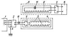
이러한 장치는 전력원(1)을 포함하고, 380V/3p/50㎐의 HF(1.0 내지 30.0㎑) 단일 위상 전류 변환기(2)가 전력원(1)의 단자들에 접속된다. 변환기(2) 출력에서의 전류 주파수는 조작자에 의해 또는 자동적으로 조정될 수 있다. 주파수 변환기 출력(2)은 플랫 2중-와이어 나선 와인딩(3)의 주변 리드들에 접속된다. 플랫 2중-와이어 나선 와인딩의 중앙 리드들은 서로 절연되고 전송기(4)의 전도성 부품들과 구성요소들로부터 절연된다. 전술한 바와 같이 구현된 플랫 2중-와이어 와인딩(3)은 주파수 조정 가능한 주파수 변환기(2)로부터 동력이 공급된 플랫 나선으로 뚤뚤 말린 긴 오픈-엔디드(open-ended) 라인을 나타낸다. 만약 주파수 변환기(2)가 2중-와이어 나선(3)으로 뚤뚤 말린 긴 라인을 따라서, 와인딩(3)의 1/4파 공진의 주파수로 설정된다면, 전류 및 전위 정상파들이 절연된 리드들 사이의 중심에서의 전류 최대치와, 주파수 변환기(2)의 출력 단자들에 접속되는 주변부 리드들에서의 전류 최대치로 여기된다. 최소 전류는 긴 라인(3)의 개방되고 절연된 리드들에서 형성되고, 최소 전위는 라인(3)의 입력 주변 리드들에서 여기된다. 2중-와이어 나선 와인딩(3)에서의 전류 및 전위 최소치들과 최대치들의 이러한 설계에 관해서, 2중-와이어 와인딩(3)의 자기장은 와인딩(3)의 주변부에서의 최소 전류의 위치로 인해 와인딩 주변부 쪽으로 감소하지 않고, 이는 주변부에서의 자기장이 에너지 수신기(5)의 전자기 수신기 유닛(6)으로의 에너지 전송에 효과적으로 관여하는 것을 가능하게 한다. 단일-와이어 나선 와인딩(6)에서의 여기된 에너지는, 변환기(7)를 거쳐 고주파 전류 에너지로부터 수신기(5)에서의 전력 저장장치(8)의 정상적인 작동을 위해 필요한 전류 포맷을 갖는 에너지로 전송된다. 플랫 단일-와이어 나선 와인딩(6)은 전송기(4)의 2중-와이어 1/4파 와인딩(3)의 전자기 교번 자장(alternating field)에 놓인 정상적인 비공진 와인딩으로서 기능을 한다.This device comprises a
나선의 중심 부분에서의 리드들이 분리될 때에는, 플랫 2중-와이어 나선 와인딩(3)이 전송기(4)에서 기능을 하는 것과 같은 방식으로, 도 2에서의 수신기(5)에서의 플랫 2중-와이어 나선 와인딩(6)이 2중-와이어의 긴 라인의 끝에서 개방된 뚤둘 말린 나선으로서 기능을 하기 시작한다. 최대 전위는 와인딩(6)의 중심 부분에서 여기되고, 최대 전류는 와인딩(6)의 주변부에서 여기된다. 그러므로 와인딩(6)에서의 자속의 최대 유도는 와인딩(6)의 주변부에서 여기되고, 이는 나선 2중-와이어 와인딩(3)의 전체 영역을 따라서 에너지 플럭스 밀도의 높은 규칙성을 보장한다.When the leads in the central portion of the helix are separated, the flat double-flat double in the
도 3에서의 전송기(4)의 플랫 2중-와이어 나선 와인딩(3)에서의 주변 리드들의 접속은 공업용 AC 메인들(industrial AC mains)로부터의 플랫 2중-와이어 나선 와인딩(3)의 갈바닉 절연(galvanic isolation)을 보장하고, 이는 고정되고 이동성이 있는 전력 수용가들의 무선 충전기와 충전 스테이션의 사용자들과 에너지 저장장치들의 작동 요원에 관한 충전기로부터의 부상 위험을 상당히 감소시킨다.The connection of the peripheral leads in the flat double-wire spiral winding 3 of the
도 4와 도 5에 도시된 것처럼, 컨덴서들(condensers)(10, 11)의 전송기(4)와 수신기(5)의 공급 및 배출 루프들로의 접속은 전송기(4)에서의 공급 결합 와인딩(9)으로의 펌핑 에너지와 수신기(5)에서의 단일 층 나선 와인딩(6)의 수신기로부터의 배출 에너지에 관한 직렬 공진의 출현을 위한 필수적인 조건을 생성한다.As shown in FIGS. 4 and 5, the connection of the
전송기(4)에서 공급 와인딩(9)을 쪼개는 것은 와인딩(3)으로의 투-웨이(two-way) 에너지 펌핑으로 인해 2중-와이어 전송 와인딩(3)(도 6)으로의 펌핑 에너지의 과정(process)의 신뢰성을 증가시키고, 충전기로의 펌핑 에너지에 관한 유닛의 냉각 조건을 단순화시킨다.Splitting the supply winding 9 at the
고정되거나 이동성이 있는 수용가에서의 전기 에너지 저장장치의 무선 충전을 위한 샘플 방법 및 장치가 설명된다.Sample methods and apparatus for wireless charging of electrical energy storage in fixed or mobile consumers are described.
사례(case) 1.
공급 전송 코일(3)은 0.75㎟과 90회의 턴(turn)을 갖는 단면적을 갖는 2중 구리 와이어로 이루어진다. 와인딩 도체들은 동일한 평면에 위치하여 2중-와이어 아르키메데스 나선(Archimedean spiral)을 형성한다. 나선 와인딩의 내부 직경은 100㎜이고, 외부 직경은 480㎜이다. 각각의 나선의 인덕턴스는 5.1mH이다. 2중-와이어 나선 와인딩은 플랫 나선으로 뚤뚤 말린 1/4파 오픈 엔드 긴 라인이다. 라인 단부(line end)들은 서로 절연된다. 나선 와이어들 사이의 커패시턴스는 30.5㎋이다. 2중-와이어 나선 와인딩에서의 도체들의 저항은 2.3Ω와 2.4Ω이다. 공진 주파수는 f0=64-60㎑이다. 수신기(5)의 코일(6)은 내부 직경이 100㎜인 플랫 단일-와이어 나선 와인딩을 나타낸다. 와인딩 인덕턴스는 0.3mH이다. 100W의 전력과 최대 7%인 소비율(dissipation)을 갖는 전기 에너지가 수평 평면에서 2개의 서로 가로지르는 방향들로 움직일 때 전송기(3)와 수신기(6) 사이의 수직 방향으로 0.5m의 거리(중심으로부터 ±0.3m)에서 펌핑되었다.The
사례 2.
도 1에서와 같이 에너지 전송 조건에서, 에너지는 펌핑 와인딩(9)을 사용하여 공급 와인딩(3) 내로 펌핑되었다. 펌핑 와인딩(9)은 2.5㎟의 단면적과 3회의 턴을 가지고 구리 와이어로 만들어진다. 와인딩(9)의 인덕턴스는 18.5μH이다. 와인딩(9)은 직렬로 접속된 전기 커패시터(10)를 거쳐 주파수 변환기(2)의 출력에 접속된다. 커패시터(10)의 커패시턴스는 180㎋이다. 와인딩(3)의 리드들은 단락되었다. 사례 1과 동일한 시험 조건 하에서의 전송기 전력 소비의 주변 측정은 중심으로부터 ±0.3m의 오차로 7%를 넘지 않으면서 수신기 와인딩의 편차로 소비되는 비슷한 결과를 산출해 내었다.In the energy transfer conditions as in FIG. 1, energy was pumped into the supply winding 3 using a pumping winding 9. The pumping winding 9 is made of copper wire with a cross section of 2.5
사례 1 및 사례 2에서와 같은 전력 전송의 조건 하에서는, 100W의 전력을 갖는 에너지가 1.0m의 거리까지 전송되었다. 이러한 소비는 최대 10%이었다.Under the conditions of power transmission as in
그러므로, 0.5m와 1.0m의 거리들에서의 전력 전송 시험들은 약 0.3㎡의 면적에서 이동 전화기들, 랩톱들, 태블릿, PC들 등과 같은 저전력 도구들(low-power gadget)들에 관한 전자기장 강도의 불규칙성이 10% 보다 나쁘지 않음을 입증하였다. 이 사례에서의 평균 전자기 에너지 플럭스 강도는 약 0.3㎾/㎡와 같았다.Therefore, power transmission tests at distances of 0.5 m and 1.0 m have been tested for field strength on low-power gadgets such as mobile phones, laptops, tablets, PCs, etc. in an area of about 0.3
사례 3.
전송 공급 코일(3)은 단면적이 0.25㎟인 2중 구리 다중 도체 와이어 PVMTg-40로 이루어지고, 그 절연 세기는 40㎸ DC이며, 절연시의 외부 직경은 4.2㎜이다. 그러한 와인딩은 2.5m×1.0m인 외부 치수들을 갖는 플랫 직사각형 나선의 형태로 되어 있다. 2중 턴들의 개수는 150이다. 와인딩의 내부 리드들은 서로 절연된다. 외부 리드들은 공급 주파수 변환기에 접속된다. 공급 전류 주파수는 11㎑이다. 2중-와이어 와인딩에서의 각각의 브랜치의 인덕턴스는 6.2mH이다. 각각의 브랜치의 DC 저항은 11Ω이다. 수신기 코일은 단면적인 16㎟인 구리로 된 멀티-코어(multi-core) 와이어로 이루어진다. 수신기 코일은 1.4m×0.5m인 치수들을 가진다. 턴들의 개수는 25이다. 인덕턴스는 1.2mH이다. DC 저항은 0.16Ω이다. 전송기와 수신기 코일들 사이의 거리는 0.3m이고, 전송된 전력은 2.0㎾이다.The
중심 위치로부터 4개의 사이드들 중 임의의 것 쪽으로의 0.5m만큼의 편차가 있는 경우에서의 전력 불규칙성은 최대 10%이었다. 평균 전자기 에너지 플럭스 강도는 약 3.0㎾/㎡와 같았다.The power irregularity in the case of a deviation of 0.5m from the center position toward any of the four sides was at most 10%. The average electromagnetic energy flux intensity was equal to about 3.0 mA /
그러므로 ±0.5m(전송 코일 폭의 절반)만큼 수신기 코일을 옮겨 놓음으로써 2.0㎾의 전력으로 0.3m의 거리까지의 전송을 위한 전기 에너지 플럭스 불규칙성은 전력 소비율이 10%를 넘지 않는다는 것을 입증하였다.Therefore, by shifting the receiver coil by ± 0.5m (half the width of the transmitting coil), the electrical energy flux irregularities for transmissions up to 0.3m at 2.0kW prove that power consumption is no more than 10%.
사례 3에서와 같은 장치는, 충전기 및 서비스되어지는 유닛 또는 기구의 상호 위치선정을 위한 임의의 엄격한 요구 조건 없이, 자동차들, 전기 카트들, 또는 쿼드콥터들과 같은 이동성이 있는 기구들의 배터리들을 충전하기 위해 사용될 수 있고, 이 경우 몇몇 기구들은 동시에 나란하게 서비스되어질 수 있다. 제안된 본 발명은 고정되거나 이동성이 있는 전기 수용가에서 전기 에너지 저장장치의 무선 충전, 즉 교통 신호들 등과 교차하는 도로에서 이동성이 있는 전기 수용가가 존재할 때에서 움직이고 있는 동안의 차량들인 특별한 무선 충전 스테이션들에서 전기 에너지 저장장치를 충전하고 재충전하는 것, 큰 방들에서의 이동 전화기들, 랩톱들, 태블릿 PC들에서 에너지 저장장치들을 충전하고 재충전하는 것, 쿼드콥터들, 사람의 존재가 바람직하지 않은 자동 시스템들의 작동 조건(매우 낮은 작동 온도들을 갖는 창고들, 주위 환경의 특별한 구성을 갖는 창고들 등) 하에서 큰 창고들과 베이스(base)들, 및 저장소들에서의 화물(cargo) 이동의 자동화된 물류유통(logistical) 시스템들에서 에너지 저장장치들을 충전하고 재충전하는 가능성을 제공한다.The device as in
Claims (12)
Translated fromKorean상기 전력 수용가에서 전력원으로부터 전력 수신기로의 전기 에너지 전송을 포함하고, 전력원 포맷으로부터 고주파 AC 전류 포맷으로의 변환을 위해 제어되고 주파수 조정 가능한 전류 변환기(a controlled and frequency-adjustable electrical current converter)를 사용하고, 자기 공진 결합을 갖는 수신기와 전송기, 고주파 포맷으로부터 충전되고 있는 상기 전기 에너지 저장장치의 정상적인 작동을 위해 요구되는 포맷으로의 변환을 위한 전류 변환기를 포함하고,
상기 전송기의 상기 자기 공진 와인딩은 중심으로부터 주변부까지 2중-와이어 와인딩을 갖는 플랫 나선(flat spiral)으로 이루어지고; 상기 수신기의 상기 자기 공진 와인딩은 플랫 단일-와이어 나선(flat single-wire spiral)으로 이루어지며; 상기 전송기의 상기 자기 공진 와인딩은 상기 전송기의 상기 자기 공진 와인딩에서의 상기 와인딩 주변부에서 최대 전류로 전류 및 전위 정상파들(current and potential standing waves)을 여기하기 위해 사용되고; 전류 정상파의 전자기장을 사용하여 상기 전송기와 수신기 사이에 에너지 전송이 마련되며(arranged), - 이를 위해, 상기 전송기의 상기 2중-와이어 나선 와인딩의 상기 중심 부분에서의 상기 리드들은 조정 가능한 고주파수들로 변환기들의 상기 출력 단자들에 접속되고, 고정되거나 이동성이 있는 수용가의 상기 수신기에서의 단일-와이어 나선 와인딩의 상기 리드들은 고주파 전류를 충전되고 있는 상기 에너지 저장장치의 정상적인 작동을 위해 요구되는 포맷으로 변환하기 위해 상기 변환기에 접속되는 것을 특징으로 하는, 무선 충전 방법.In a wireless charging method of electrical energy storage (electric energy storage) in a fixed or mobile power consumer,
A controlled and frequency-adjustable electrical current converter comprising electrical energy transfer from the power source to the power receiver at the power consumer and for conversion from the power source format to the high frequency AC current format. A receiver and transmitter having a magnetic resonance coupling, and a current converter for conversion from a high frequency format to a format required for normal operation of the electrical energy storage being charged,
The self resonant winding of the transmitter consists of a flat spiral with double-wire windings from the center to the periphery; The magnetic resonance winding of the receiver consists of a flat single-wire spiral; The self resonant winding of the transmitter is used to excite current and potential standing waves with maximum current at the winding periphery in the self resonant winding of the transmitter; Energy transfer is arranged between the transmitter and receiver using an electromagnetic field of current standing wave, for which the leads at the center portion of the double-wire helix winding of the transmitter are at adjustable high frequencies. The leads of a single-wire spiral winding in the receiver of a fixed or mobile consumer connected to the output terminals of the transducers convert high frequency current into the format required for normal operation of the energy storage being charged. Connected to the converter for the purpose of wireless charging.
상기 전송기의 상기 자기 공진 와인딩은 상기 중심으로부터 상기 주변부로 이어지는 와인딩 턴들(winding turn)들을 갖는 플랫 2중-와이어 나선(flat double-wire spiral)으로 이루어지고; 상기 수신기에서의 상기 2중-와이어 와인딩의 상기 고유 공진 주파수는 상기 전송기에서의 상기 플랫 2중-와이어 나선 와인딩의 상기 공진 주파수와 같고; 상기 수신기에서의 상기 2중-와이어 나선 와인딩의 상기 중심 부분에서의 상기 리드들은, 서로 절연되고 상기 수신기의 다른 전도성 부품들 및 구성요소들로부터 절연되며; 상기 나선 2중-와이어 와인딩의 상기 주변부로부터의 상기 리드들은, 충전되고 있는 상기 에너지 저장장치의 정상적인 작동을 위해 요구되는 전류로의 고주파 전류의 변환을 위해 상기 변환기의 상기 입력과 접속되고; 상기 출력 단자들은 상기 수신기에서 상기 에너지 저장장치의 상기 인입 단자들(incoming terminals)에 접속되는, 무선 충전 방법.The method of claim 1,
The self resonant winding of the transmitter consists of a flat double-wire spiral having winding turns from the center to the periphery; The natural resonant frequency of the double-wire winding at the receiver is equal to the resonant frequency of the flat double-wire spiral winding at the transmitter; The leads in the central portion of the double-wire spiral winding in the receiver are insulated from each other and insulated from other conductive parts and components of the receiver; The leads from the periphery of the spiral double-wire winding are connected to the input of the converter for conversion of high frequency current into a current required for normal operation of the energy storage device being charged; And the output terminals are connected at the receiver to the incoming terminals of the energy storage device.
상기 전송기에서의 상기 플랫 2중-와이어 나선 와인딩의 상기 주변 리드들은 단락되고, 상기 변환기 출력으로부터의 상기 전력은 자기 결합 코일을 사용하여 상기 전송기의 플랫 2중-와이어 나선 와인딩에 공급되며; 상기 2중-와이어 나선 와인딩의 상기 평면 상에서, 상기 자기 결합 코일은 상기 주변부에서 상기 전송기의 상기 2중-와이어 나선 와인딩을 덮는 것을 특징으로 하는, 무선 충전 방법.The method according to claim 1 or 2,
The peripheral leads of the flat double-wire spiral winding at the transmitter are short-circuited and the power from the converter output is supplied to the flat double-wire spiral winding of the transmitter using a magnetic coupling coil; On the plane of the double-wire helix winding, wherein the magnetic coupling coil covers the double-wire helix winding of the transmitter at the periphery.
상기 전송기에서 상기 플랫 2중-와이어 나선 와인딩의 상기 자기 결합 코일은, 결합 코일로 공진 루프를 형성하는 커패시터를 통해 상기 전류 변환기 출력에 접속되고; 상기 직렬 공진 루프의 상기 고유 공진 주파수는 상기 전송기의 상기 플랫 2중-와이어 나선 와인딩의 상기 공진 주파수와 같은 것을 특징으로 하는, 무선 충전 방법.The method of claim 3, wherein
The magnetic coupling coil of the flat double-wire spiral winding in the transmitter is connected to the current converter output through a capacitor which forms a resonant loop with a coupling coil; The natural resonant frequency of the series resonant loop is equal to the resonant frequency of the flat double-wire helix winding of the transmitter.
상기 수신기의 상기 단일-와이어 플랫 나선 와인딩은, 상기 수신기의 상기 단일-와이어 플랫 나선 와인딩으로 직렬 공진 루프를 형성하는 커패시터를 통해, 에너지 저장장치의 작동을 위해 요구되는 상기 포맷으로 상기 고주파 전류를 변환하기 위해 상기 변환기 입력에 접속되고; 상기 형성된 루프의 상기 공진 주파수는 상기 전송기에서 상기 플랫 2중-와이어 와인딩의 상기 공진 주파수와 같은 것을 특징으로 하는, 무선 충전 방법.The method according to any one of claims 1, 3, and 4,
The single-wire flat spiral winding of the receiver converts the high frequency current into the format required for operation of an energy storage device through a capacitor that forms a series resonant loop with the single-wire flat spiral winding of the receiver. Connected to the transducer input to; And wherein said resonant frequency of said formed loop is equal to said resonant frequency of said flat double-wire winding at said transmitter.
상기 전류 변환기 출력으로부터 상기 전송기의 상기 플랫 2중-와이어 나선 와인딩으로 전기 에너지를 전송하기 위한 자기 결합의 상기 코일은, 상기 플랫 2중 나선 와인딩의 대향하는 단부들에서 상기 주변부를 따라서 위치하는 2개의 원형 하프 와인딩들로 이루어지고; 상기 원형 하프 와인딩들은 직렬로 그리고 일관되게(consistently) 전기적으로 상호 접속되는 것을 특징으로 하는, 무선 충전 방법.The method according to any one of claims 3 to 5,
The coil of magnetic coupling for transferring electrical energy from the current converter output to the flat double-wire helix winding of the transmitter is located along the periphery at opposing ends of the flat double helix winding. Consisting of circular half windings; And the circular half windings are electrically interconnected in series and consistently.
전력원 포맷으로부터 고주파 교류 전류 포맷으로 전류를 변환하기 위해, 제어되고 주파수 조정 가능한 전류 변환기에 결합되는 전력원, 자기 공진 결합을 갖는 수신기와 전송기, 및 상기 전류를 고주파 전류 포맷으로부터 충전되고 있는 상기 에너지 저장장치의 정상적인 작동을 위해 요구되는 포맷으로의 변환을 위한 변환기를 포함하고,
상기 전송기의 자기 공진 와인딩은 중심으로부터 주변부까지 2중-와이어 와인딩을 갖는 플랫 나선으로 이루어지고; 상기 수신기의 자기 공진 와인딩은 플랫 단일-와이어 나선을 나타내고; 상기 전송기의 상기 자기 공진 와인딩과 상기 수신기의 상기 자기 공진 와인딩 사이에서 전자기장을 사용하여 전기 에너지가 전송되고; 상기 자기 공진 와인딩의 상기 주변부 리드들은, 전기 에너지 소스 포맷으로부터 고주파 전류 포맷으로 전류를 변환하기 위해 상기 주파수 변환기의 상기 출력 단자들에 접속되고; 상기 2중-와이어 나선 와인딩의 중심 부분의 리드들은 서로 절연되고 상기 전송기의 다른 전도성 부품들 및 구성요소들로부터 절연되며; 상기 수신기에서의 상기 단일-와이어 나선 와인딩의 상기 리드들은, 고주파 전류를 충전되고 있는 상기 에너지 저장장치의 정상적인 작동을 위해 요구되는 포맷으로 변환하기 위해, 상기 변환기의 상기 입력 단자들에 결합되고, 상기 변환기의 상기 출력 단자들은 고정되거나 이동성이 있는 수용가의 상기 수신기에서 에너지 저장장치의 상기 단자들에 접속되는 것을 특징으로 하는, 무선 충전 시스템.In the wireless charging system of the energy storage device in a fixed or mobile consumer,
A power source coupled to a controlled, frequency adjustable current converter, a receiver and transmitter with a magnetic resonance coupling, and the energy being charged from the high frequency current format to convert current from a power source format to a high frequency alternating current format. A converter for conversion to a format required for normal operation of the storage device,
The self-resonant winding of the transmitter consists of a flat helix with double-wire windings from the center to the periphery; The self resonant winding of the receiver exhibits a flat single-wire helix; Electrical energy is transferred using an electromagnetic field between the magnetic resonance winding of the transmitter and the magnetic resonance winding of the receiver; The peripheral leads of the self resonant winding are connected to the output terminals of the frequency converter to convert current from an electrical energy source format to a high frequency current format; The leads of the central portion of the double-wire spiral winding are insulated from each other and from other conductive parts and components of the transmitter; The leads of the single-wire helix winding at the receiver are coupled to the input terminals of the converter to convert a high frequency current into a format required for normal operation of the energy storage being charged, and And said output terminals of the converter are connected to said terminals of an energy storage device at said receiver of a fixed or mobile consumer.
상기 수신기의 상기 자기 공진 와인딩은 중심으로부터 주변부로 이어지는 와인딩 턴들을 갖는 2중-와이어 나선으로 이루어지고; 상기 수신기에서 상기 2중-와이어 나선 와인딩의 상기 중심 부분에서의 상기 리드들은 서로 절연되고 상기 수신기의 다른 전도성 부품들 및 구성요소들로부터 절연되며, 상기 나선 2중-와이어 와인딩의 상기 주변부로부터의 상기 리드들은, 고주파 전류를 충전되고 있는 상기 저장장치의 정상적인 작동을 위해 요구되는 상기 전류로 변환하기 위해 상기 변환기의 상기 입력에 접속되고; 상기 변환기들의 상기 출력 단자들은 상기 입력 에너지 저장장치 단자들에 접속되고, 상기 수신기에서의 상기 2중-와이어 와인딩의 고유 공진 주파수는 상기 전송기의 상기 플랫 2중-와이어 나선 와인딩의 공진 주파수와 같은, 무선 충전 디바이스.The method of claim 7, wherein
The self-resonant winding of the receiver consists of a double-wire helix having winding turns from the center to the periphery; The leads in the central portion of the double-wire spiral winding in the receiver are insulated from each other and insulated from other conductive parts and components of the receiver and from the periphery of the spiral double-wire winding. Leads are connected to the input of the converter to convert a high frequency current into the current required for normal operation of the storage device being charged; The output terminals of the transducers are connected to the input energy storage terminals, and the natural resonant frequency of the double-wire winding at the receiver is equal to the resonant frequency of the flat double-wire spiral winding of the transmitter. Wireless charging device.
상기 전송기에서의 상기 2중-와이어 나선 와인딩의 상기 주변부 리드들은 단락되고; 상기 주파수 변환기와 상기 플랫 2중-와이어 나선 와인딩을 결합하기 위한 자기 결합 코일이 상기 2중-와이어 나선 와인딩의 평면에 위치하고; 상기 결합 코일 리드들은 상기 전류를 상기 전력원 포맷으로부터 고주파 전류 포맷으로 변환하기 위해, 상기 주파수 변환기의 상기 출력 단자들에 접속되는 것을 특징으로 하는, 무선 충전 디바이스.The method of claim 7, wherein
The peripheral leads of the double-wire helix winding at the transmitter are shorted; A magnetic coupling coil for coupling the frequency converter and the flat double-wire spiral winding is located in the plane of the double-wire spiral winding; And the coupling coil leads are connected to the output terminals of the frequency converter to convert the current from the power source format to a high frequency current format.
상기 전송기에서의 상기 플랫 2중-와이어 나선 와인딩의 상기 자기 결합 코일은 상기 결합 코일로 발진하는 루프를 형성하는 커패시터를 통해 상기 전류 변환기 출력에 접속되고; 상기 직렬 공진 루프의 상기 고유 공진 주파수는 상기 전송기의 상기 플랫 2중-와이어 나선 와인딩의 상기 고유 공진 주파수와 같은 것을 특징으로 하는, 무선 충전 디바이스.The method of claim 9,
The magnetic coupling coil of the flat double-wire spiral winding at the transmitter is connected to the current converter output through a capacitor forming a loop oscillating to the coupling coil; The natural resonant frequency of the series resonant loop is equal to the natural resonant frequency of the flat double-wire helix winding of the transmitter.
상기 수신기의 상기 단일-와이어 플랫 나선 와인딩의 상기 리드들은, 상기 단일-와이어 플랫 나선 와인딩으로 직렬 공진 루프를 형성하는 커패시터를 통해, 상기 고주파 전류를 상기 에너지 저장장치의 작동을 위해 요구되는 상기 전류 포맷으로 변환하기 위해 상기 변환기의 상기 입력 단자들에 접속되고; 상기 수신기의 상기 직렬 공진 루프의 상기 공진 주파수는 상기 전송기에서 상기 플랫 2중-와이어 와인딩의 상기 공진 주파수와 같은 것을 특징으로 하는, 무선 충전 디바이스.The method of claim 10,
The leads of the single-wire flat spiral winding of the receiver pass the high frequency current through the capacitor to form a series resonant loop with the single-wire flat spiral winding, the current format required for operation of the energy storage device. Is connected to the input terminals of the converter for conversion to; The resonant frequency of the series resonant loop of the receiver is equal to the resonant frequency of the flat double-wire winding at the transmitter.
상기 플랫 2중-와이어 나선 와인딩의 주파수 변환기를 갖는 상기 자기 결합 코일은 2개의 원형 하프 와인딩(circular half winding)들로 이루어지고, 상기 하프 와인딩들은 상기 플랫 2중-와이어 나선 와인딩의 대향하는 단부들에서 상기 주변부를 따라서 위치하고, 상기 하프 와인딩들은 직렬로 그리고 일관되게 상호 접속되는 것을 특징으로 하는, 무선 충전 디바이스.The method of claim 9,
The magnetic coupling coil having a frequency converter of the flat double-wire spiral winding consists of two circular half windings, the half windings opposing ends of the flat double-wire spiral winding. Located along the periphery in the half windings, wherein the half windings are serially and consistently interconnected.
Applications Claiming Priority (2)
| Application Number | Priority Date | Filing Date | Title |
|---|---|---|---|
| RU2018113768ARU2699024C1 (en) | 2018-04-16 | 2018-04-16 | Method and device for wireless charging of electric energy storage unit of fixed or mobile electric consumer |
| RU2018113768 | 2018-04-16 |
Publications (1)
| Publication Number | Publication Date |
|---|---|
| KR20190120723Atrue KR20190120723A (en) | 2019-10-24 |
Family
ID=65278207
Family Applications (1)
| Application Number | Title | Priority Date | Filing Date |
|---|---|---|---|
| KR1020190044484ACeasedKR20190120723A (en) | 2018-04-16 | 2019-04-16 | Method and device for wireless charging of electrical energy storage in a fixed or mobile consumer |
Country Status (7)
| Country | Link |
|---|---|
| US (2) | US20190319490A1 (en) |
| EP (1) | EP3557720B1 (en) |
| KR (1) | KR20190120723A (en) |
| CN (1) | CN110391696A (en) |
| CA (1) | CA3034072A1 (en) |
| ES (1) | ES2897546T3 (en) |
| RU (1) | RU2699024C1 (en) |
Families Citing this family (2)
| Publication number | Priority date | Publication date | Assignee | Title |
|---|---|---|---|---|
| RU2751094C1 (en)* | 2020-12-18 | 2021-07-08 | Фолкуер Холдингс Лимитед | Electric energy transmission system |
| DE102024103271A1 (en)* | 2024-02-06 | 2025-08-07 | Universität Stuttgart, Körperschaft Des Öffentlichen Rechts | Method and system for inductive transmission of electrical energy, as well as method for producing an inductive energy transmission system |
Family Cites Families (13)
| Publication number | Priority date | Publication date | Assignee | Title |
|---|---|---|---|---|
| US6960968B2 (en)* | 2002-06-26 | 2005-11-01 | Koninklijke Philips Electronics N.V. | Planar resonator for wireless power transfer |
| KR20040072581A (en)* | 2004-07-29 | 2004-08-18 | (주)제이씨 프로텍 | An amplification relay device of electromagnetic wave and a radio electric power conversion apparatus using the above device |
| RU2411142C2 (en) | 2009-01-29 | 2011-02-10 | Российская Академия сельскохозяйственных наук Государственное научное учреждение Всероссийский научно-исследовательский институт электрификации сельского хозяйства (ГНУ ВИЭСХ РОССЕЛЬХОЗАКАДЕМИИ) | Method of electric power wireless transmission and device to this end |
| JP5459058B2 (en)* | 2009-11-09 | 2014-04-02 | 株式会社豊田自動織機 | Resonant contactless power transmission device |
| RU2505427C2 (en)* | 2011-12-28 | 2014-01-27 | Российская академия сельскохозяйственных наук Государственное научное учреждение Всероссийский научно-исследовательский институт электрификации сельского хозяйства Российской академии сельскохозяйственных наук (ГНУ ВИЭСХ Россельхозакадемии) | Contactless method of powering electric vehicles |
| RU2510558C1 (en)* | 2012-07-19 | 2014-03-27 | Александр Викторович Атаманов | Wireless charging system for low-power consumers of electrical energy |
| KR20140076993A (en)* | 2012-12-13 | 2014-06-23 | 엘지이노텍 주식회사 | Wireless power device |
| CN103915916B (en)* | 2014-04-23 | 2016-08-31 | 慈溪市源顺光电科技有限公司 | Magnetic resonance wireless electric energy transmission device based on planar magnetic resonance coupling coil structure |
| US9887557B2 (en)* | 2014-09-11 | 2018-02-06 | Cpg Technologies, Llc | Hierarchical power distribution |
| RU2623095C2 (en)* | 2014-12-16 | 2017-06-22 | Самсунг Электроникс Ко., Лтд. | Wireless charging system and its application for charging mobile and portable devices |
| WO2016114637A1 (en)* | 2015-01-16 | 2016-07-21 | 주식회사 한림포스텍 | Wireless power transmission device |
| US10075024B2 (en)* | 2015-05-22 | 2018-09-11 | La-Z-Boy Incorporated | Apparatus and method for wireless power transfer in furniture |
| US9893403B2 (en)* | 2015-09-11 | 2018-02-13 | Cpg Technologies, Llc | Enhanced guided surface waveguide probe |
- 2018
- 2018-04-16RURU2018113768Apatent/RU2699024C1/enactive
- 2019
- 2019-02-01EPEP19154982.3Apatent/EP3557720B1/enactiveActive
- 2019-02-01ESES19154982Tpatent/ES2897546T3/enactiveActive
- 2019-02-15CACA3034072Apatent/CA3034072A1/enactivePending
- 2019-02-27USUS16/287,446patent/US20190319490A1/ennot_activeAbandoned
- 2019-02-27CNCN201910144950.4Apatent/CN110391696A/enactivePending
- 2019-04-16KRKR1020190044484Apatent/KR20190120723A/ennot_activeCeased
- 2020
- 2020-12-16USUS17/124,377patent/US20210104915A1/ennot_activeAbandoned
Also Published As
| Publication number | Publication date |
|---|---|
| US20190319490A1 (en) | 2019-10-17 |
| US20210104915A1 (en) | 2021-04-08 |
| CA3034072A1 (en) | 2019-10-16 |
| EP3557720A1 (en) | 2019-10-23 |
| EP3557720B1 (en) | 2021-08-11 |
| RU2699024C1 (en) | 2019-09-03 |
| CN110391696A (en) | 2019-10-29 |
| ES2897546T3 (en) | 2022-03-01 |
Similar Documents
| Publication | Publication Date | Title |
|---|---|---|
| US10374463B2 (en) | Power feeding device and contactless power feeding system provided with power feeding device | |
| RU2731628C2 (en) | Systems and methods for wireless transmission of energy | |
| US10158253B2 (en) | Wireless power relay device and wireless power transmission system | |
| KR20130102218A (en) | Wireless power receiving device with multi coil and wireless power receiving method | |
| US20150076921A1 (en) | Resonating apparatus with increased isolation for stable wireless power transmission | |
| JP2017077166A (en) | Coil device, method for manufacturing coil device, wireless power transfer device including coil device, and wireless power receiver device {coil device of wireless power transfer system} | |
| CN102593959A (en) | Non-contact power transmission apparatus and power transmission method therefor | |
| Shadid et al. | A literature survey of wireless power transfer | |
| US20120119587A1 (en) | Wireless power transfer device | |
| RU2411142C2 (en) | Method of electric power wireless transmission and device to this end | |
| US20230369895A1 (en) | Systems and methods for wireless power transferring | |
| US11605976B2 (en) | System and method for wireless transmission of power | |
| KR20190120723A (en) | Method and device for wireless charging of electrical energy storage in a fixed or mobile consumer | |
| US8760009B2 (en) | Wireless power source | |
| JP2014176133A (en) | Power feeding unit, power receiving unit, and power feeding system | |
| Bhutkar et al. | Wireless energy transfer using magnetic resonance | |
| WO2021053502A1 (en) | Method and apparatus for transmission of electrical energy (embodiments) | |
| US10491043B2 (en) | Resonant coil, wireless power transmitter using the same, wireless power receiver using the same | |
| KR20170005589A (en) | Apparatus for transmitting wireless power and system for transmitting wireless power | |
| JP2019170017A (en) | Wireless power transmission system | |
| CN209994166U (en) | Wireless power transmission system with monopole NFP relay structure | |
| KR20120116801A (en) | A wireless power transmission circuit, a wireless power transmitter and receiver | |
| JP2015220891A (en) | Resonator and wireless power supply system | |
| JP5847468B2 (en) | Power supply system design method | |
| JP2013046435A (en) | Charger mounted on vehicle, and power supply for vehicle |
Legal Events
| Date | Code | Title | Description |
|---|---|---|---|
| PA0109 | Patent application | Patent event code:PA01091R01D Comment text:Patent Application Patent event date:20190416 | |
| PG1501 | Laying open of application | ||
| PA0201 | Request for examination | Patent event code:PA02012R01D Patent event date:20210413 Comment text:Request for Examination of Application Patent event code:PA02011R01I Patent event date:20190416 Comment text:Patent Application | |
| E902 | Notification of reason for refusal | ||
| PE0902 | Notice of grounds for rejection | Comment text:Notification of reason for refusal Patent event date:20221101 Patent event code:PE09021S01D | |
| E601 | Decision to refuse application | ||
| PE0601 | Decision on rejection of patent | Patent event date:20230202 Comment text:Decision to Refuse Application Patent event code:PE06012S01D Patent event date:20221101 Comment text:Notification of reason for refusal Patent event code:PE06011S01I |