KR20190119682A - Vapour provision system and cartridge therefor - Google Patents
Vapour provision system and cartridge thereforDownload PDFInfo
- Publication number
- KR20190119682A KR20190119682AKR1020197030281AKR20197030281AKR20190119682AKR 20190119682 AKR20190119682 AKR 20190119682AKR 1020197030281 AKR1020197030281 AKR 1020197030281AKR 20197030281 AKR20197030281 AKR 20197030281AKR 20190119682 AKR20190119682 AKR 20190119682A
- Authority
- KR
- South Korea
- Prior art keywords
- cartridge
- inner container
- outer housing
- mouthpiece
- longitudinal axis
- Prior art date
- Legal status (The legal status is an assumption and is not a legal conclusion. Google has not performed a legal analysis and makes no representation as to the accuracy of the status listed.)
- Granted
Links
Images


Classifications
- A24F47/008—
- A—HUMAN NECESSITIES
- A24—TOBACCO; CIGARS; CIGARETTES; SIMULATED SMOKING DEVICES; SMOKERS' REQUISITES
- A24F—SMOKERS' REQUISITES; MATCH BOXES; SIMULATED SMOKING DEVICES
- A24F40/00—Electrically operated smoking devices; Component parts thereof; Manufacture thereof; Maintenance or testing thereof; Charging means specially adapted therefor
- A24F40/40—Constructional details, e.g. connection of cartridges and battery parts
- A24F40/42—Cartridges or containers for inhalable precursors
- A—HUMAN NECESSITIES
- A24—TOBACCO; CIGARS; CIGARETTES; SIMULATED SMOKING DEVICES; SMOKERS' REQUISITES
- A24B—MANUFACTURE OR PREPARATION OF TOBACCO FOR SMOKING OR CHEWING; TOBACCO; SNUFF
- A24B15/00—Chemical features or treatment of tobacco; Tobacco substitutes, e.g. in liquid form
- A24B15/10—Chemical features of tobacco products or tobacco substitutes
- A24B15/16—Chemical features of tobacco products or tobacco substitutes of tobacco substitutes
- A24B15/167—Chemical features of tobacco products or tobacco substitutes of tobacco substitutes in liquid or vaporisable form, e.g. liquid compositions for electronic cigarettes
- A—HUMAN NECESSITIES
- A24—TOBACCO; CIGARS; CIGARETTES; SIMULATED SMOKING DEVICES; SMOKERS' REQUISITES
- A24F—SMOKERS' REQUISITES; MATCH BOXES; SIMULATED SMOKING DEVICES
- A24F40/00—Electrically operated smoking devices; Component parts thereof; Manufacture thereof; Maintenance or testing thereof; Charging means specially adapted therefor
- A24F40/40—Constructional details, e.g. connection of cartridges and battery parts
- A24F40/46—Shape or structure of electric heating means
- A—HUMAN NECESSITIES
- A24—TOBACCO; CIGARS; CIGARETTES; SIMULATED SMOKING DEVICES; SMOKERS' REQUISITES
- A24F—SMOKERS' REQUISITES; MATCH BOXES; SIMULATED SMOKING DEVICES
- A24F40/00—Electrically operated smoking devices; Component parts thereof; Manufacture thereof; Maintenance or testing thereof; Charging means specially adapted therefor
- A24F40/40—Constructional details, e.g. connection of cartridges and battery parts
- A24F40/48—Fluid transfer means, e.g. pumps
- A24F40/485—Valves; Apertures
- A—HUMAN NECESSITIES
- A24—TOBACCO; CIGARS; CIGARETTES; SIMULATED SMOKING DEVICES; SMOKERS' REQUISITES
- A24F—SMOKERS' REQUISITES; MATCH BOXES; SIMULATED SMOKING DEVICES
- A24F40/00—Electrically operated smoking devices; Component parts thereof; Manufacture thereof; Maintenance or testing thereof; Charging means specially adapted therefor
- A24F40/50—Control or monitoring
- A—HUMAN NECESSITIES
- A61—MEDICAL OR VETERINARY SCIENCE; HYGIENE
- A61M—DEVICES FOR INTRODUCING MEDIA INTO, OR ONTO, THE BODY; DEVICES FOR TRANSDUCING BODY MEDIA OR FOR TAKING MEDIA FROM THE BODY; DEVICES FOR PRODUCING OR ENDING SLEEP OR STUPOR
- A61M11/00—Sprayers or atomisers specially adapted for therapeutic purposes
- A61M11/04—Sprayers or atomisers specially adapted for therapeutic purposes operated by the vapour pressure of the liquid to be sprayed or atomised
- A61M11/041—Sprayers or atomisers specially adapted for therapeutic purposes operated by the vapour pressure of the liquid to be sprayed or atomised using heaters
- A61M11/042—Sprayers or atomisers specially adapted for therapeutic purposes operated by the vapour pressure of the liquid to be sprayed or atomised using heaters electrical
- A—HUMAN NECESSITIES
- A61—MEDICAL OR VETERINARY SCIENCE; HYGIENE
- A61M—DEVICES FOR INTRODUCING MEDIA INTO, OR ONTO, THE BODY; DEVICES FOR TRANSDUCING BODY MEDIA OR FOR TAKING MEDIA FROM THE BODY; DEVICES FOR PRODUCING OR ENDING SLEEP OR STUPOR
- A61M15/00—Inhalators
- A61M15/06—Inhaling appliances shaped like cigars, cigarettes or pipes
- F—MECHANICAL ENGINEERING; LIGHTING; HEATING; WEAPONS; BLASTING
- F22—STEAM GENERATION
- F22B—METHODS OF STEAM GENERATION; STEAM BOILERS
- F22B1/00—Methods of steam generation characterised by form of heating method
- F22B1/28—Methods of steam generation characterised by form of heating method in boilers heated electrically
- F22B1/284—Methods of steam generation characterised by form of heating method in boilers heated electrically with water in reservoirs
- H—ELECTRICITY
- H05—ELECTRIC TECHNIQUES NOT OTHERWISE PROVIDED FOR
- H05B—ELECTRIC HEATING; ELECTRIC LIGHT SOURCES NOT OTHERWISE PROVIDED FOR; CIRCUIT ARRANGEMENTS FOR ELECTRIC LIGHT SOURCES, IN GENERAL
- H05B3/00—Ohmic-resistance heating
- H05B3/40—Heating elements having the shape of rods or tubes
- H05B3/42—Heating elements having the shape of rods or tubes non-flexible
- A—HUMAN NECESSITIES
- A24—TOBACCO; CIGARS; CIGARETTES; SIMULATED SMOKING DEVICES; SMOKERS' REQUISITES
- A24F—SMOKERS' REQUISITES; MATCH BOXES; SIMULATED SMOKING DEVICES
- A24F40/00—Electrically operated smoking devices; Component parts thereof; Manufacture thereof; Maintenance or testing thereof; Charging means specially adapted therefor
- A24F40/10—Devices using liquid inhalable precursors
- A—HUMAN NECESSITIES
- A24—TOBACCO; CIGARS; CIGARETTES; SIMULATED SMOKING DEVICES; SMOKERS' REQUISITES
- A24F—SMOKERS' REQUISITES; MATCH BOXES; SIMULATED SMOKING DEVICES
- A24F40/00—Electrically operated smoking devices; Component parts thereof; Manufacture thereof; Maintenance or testing thereof; Charging means specially adapted therefor
- A24F40/60—Devices with integrated user interfaces
Landscapes
- Engineering & Computer Science (AREA)
- Health & Medical Sciences (AREA)
- Life Sciences & Earth Sciences (AREA)
- Sustainable Development (AREA)
- Sustainable Energy (AREA)
- Physics & Mathematics (AREA)
- Thermal Sciences (AREA)
- Mechanical Engineering (AREA)
- General Engineering & Computer Science (AREA)
- Hematology (AREA)
- Public Health (AREA)
- Anesthesiology (AREA)
- Biomedical Technology (AREA)
- Heart & Thoracic Surgery (AREA)
- Veterinary Medicine (AREA)
- Animal Behavior & Ethology (AREA)
- General Health & Medical Sciences (AREA)
- Bioinformatics & Cheminformatics (AREA)
- Pulmonology (AREA)
- Chemical & Material Sciences (AREA)
- Chemical Kinetics & Catalysis (AREA)
- General Chemical & Material Sciences (AREA)
- Packaging Of Annular Or Rod-Shaped Articles, Wearing Apparel, Cassettes, Or The Like (AREA)
- Details Of Rigid Or Semi-Rigid Containers (AREA)
- Packages (AREA)
- Filling Or Discharging Of Gas Storage Vessels (AREA)
- Devices For Medical Bathing And Washing (AREA)
- Cookers (AREA)
- Treatment Of Water By Ion Exchange (AREA)
Abstract
Translated fromKoreanDescription
Translated fromKorean본 개시는, 전자 니코틴 전달 시스템(예컨대, e-시가레트)과 같은 증기 제공 시스템 또는 디바이스, 및 그러한 디바이스에서의 사용을 위한 카트리지에 관한 것이다.The present disclosure relates to vapor providing systems or devices, such as electronic nicotine delivery systems (eg, e-cigarettes), and cartridges for use in such devices.
e-시가레트들과 같은 전자 증기 제공 시스템들은 일반적으로, 증발될 액체, 전형적으로 니코틴의 리저보어(reservoir)를 제공하기 위해 카트리지(cartridge)를 포함한다. 사용자가 디바이스를 흡입하면, 가열기가 활성화되어 소량의 액체를 증발시키고, 따라서 소량의 액체는 사용자에 의해 흡입된다. 일단 액체의 리저보어가 고갈되면, 카트리지를 포함하는 디바이스의 적어도 일부분은, 새로운 카트리지로의 교체를 허용하도록 폐기될 수 있다. 그러므로, 카트리지가 대량의 소모품일 수 있기 때문에, 카트리지가 비용-효과적인 방식으로 생산될 수 있는 것이 바람직하다.Electronic vapor providing systems, such as e-cigarettes, generally include a cartridge to provide a reservoir of liquid to be evaporated, typically nicotine. When the user inhales the device, the heater is activated to evaporate a small amount of liquid, so that a small amount of liquid is inhaled by the user. Once the reservoir of liquid is depleted, at least a portion of the device containing the cartridge can be discarded to allow replacement with a new cartridge. Therefore, since the cartridge can be a large amount of consumables, it is desirable that the cartridge can be produced in a cost-effective manner.
본 개시는 첨부된 청구항들에서 규정된다.This disclosure is defined in the appended claims.
증기 제공 시스템에서 사용하기 위해 제공되는 카트리지는, 증발될 유체의 리저보어를 유지하는 내부 용기, 및 마우스피스가 내부에 형성되는 외부 하우징을 포함하고, 외부 하우징은, 내부 용기의 적어도 상당 부분에 대해, 내부 용기의 외부측을 따라서 길이 방향으로 연장된다. 내부 용기 및 외부 하우징에는 내부 용기를 외부 하우징 내에 보유하기 위해 래치 기구(latch mechanism)가 제공된다.A cartridge provided for use in a vapor delivery system includes an inner container holding a reservoir of fluid to be evaporated, and an outer housing formed therein, the outer housing having at least a substantial portion of the inner container. And extend in the longitudinal direction along the outer side of the inner container. The inner container and outer housing are provided with a latch mechanism to hold the inner container in the outer housing.
그러한 카트리지를 포함하는 증기 제공 디바이스가 또한 제공된다. 이러한 증기 제공 디바이스는 e-시가레트와 같은 전자 증기 제공 디바이스일 수 있다.A vapor providing device comprising such a cartridge is also provided. Such vapor providing device may be an electronic vapor providing device such as an e-cigarette.
도 1은, 본 개시의 일부 실시예들에 따른 e-시가레트의 개략적인 (분해) 선도이다.
도 2는, 본 개시의 일부 실시예들에 따른 도 1의 e-시가레트의 본체의 주요 기능 컴포넌트들의 개략적인 선도이다.
도 3a 및 도 3b는, 기존 설계에 따른 e-시가레트의 카트리지 부분의 개략적인 선도들이다; 특히, 도 3a 및 도 3b는, 상호 직교하는 제 1 평면 및 제 2 평면에서 취해진 두 개의 섹션들이며, 제 1 평면 및 제 2 평면 양자 모두는 e-시가레트의 길이 방향 축(LA)을 포함한다.
도 4는, 기존 설계에 따른 도 3의 e-시가레트의 카트리지 부분의 개략적인 선도이고, 카트리지 부분의 길이를 따라서 대략 중간에서 취해진, 길이 방향 축(LA)에 대해 수직인 평면에서의 카트리지 부분을 통한 섹션을 도시한다.
도 5a 및 도 5b는, 본 발명의 일부 실시예들에 따른 e-시가레트를 위한 카트리지의 일 구현을 예시하며, 도 5a는 카트리지를 통한 (길이 방향 축을 포함하는) 수평 단면이고, 반면에 도 5b는, 내부 컨테이너 단독의 (즉, 외부 하우징 내부측으로부터 제거된 바와 같은) 도면이다.
도 6a 및 도 6b는, 본 발명의 일부 실시예들에 따른 e-시가레트를 위한 카트리지의 일 구현을 예시하며, 도 6a는 카트리지를 통한 (길이 방향 축을 포함하는) 수평 단면이고, 반면에 도 6b는, 내부 컨테이너 단독의 (즉, 외부 하우징 내부측으로부터 제거된 바와 같은) 도면이다.
도 7a 및 도 7b는, 본 발명의 일부 실시예들에 따른 e-시가레트를 위한 카트리지의 일 구현을 예시하며, 도 7a는 카트리지를 통한 (길이 방향 축을 포함하는) 수평 단면이고, 반면에 도 7b는, 내부 컨테이너 단독의 (즉, 외부 하우징 내부측으로부터 제거된 바와 같은) 마우스 단부 부분의 도면이다.
도 8a 및 도 8b는, 본 발명의 일부 실시예들에 따른 e-시가레트를 위한 카트리지의 일 구현을 예시하며, 도 8a는 카트리지를 통한 (길이 방향 축을 포함하는) 수평 단면이고, 반면에 도 8b는, 내부 컨테이너 단독의 (즉, 외부 하우징 내부측으로부터 제거된 바와 같은) 도면이다.
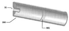
도 9a, 도 9b, 및 도 9c는 본 발명의 일부 실시예에 따른 e-시가레트를 위한 카트리지의 일 구현을 예시하며, 도 9a는 카트리지를 통한 (길이 방향 축을 포함하는) 수평 단면이고, 도 9b는, 수직 평면(길이 방향 축 포함)에서 하향 구획된 외부 하우징(즉, 내부 용기가 없음)의 도면이며, 도 9c는 내부 용기 단독의 (즉, 외부 하우징 내부측으로부터 제거된 바와 같은) 도면이다.
도 10은, 본 발명의 일부 실시예들에 따른 e-시가레트를 위한 카트리지의 일 구현을 예시하며, 카트리지를 통한 수평 단면(길이 방향 축 포함)을 도시한다.1 is a schematic (decomposition) diagram of an e-cigarette in accordance with some embodiments of the present disclosure.
2 is a schematic diagram of main functional components of the body of the e-cigarette of FIG. 1 in accordance with some embodiments of the present disclosure.
3A and 3B are schematic diagrams of a cartridge portion of an e-cigarette according to an existing design; In particular, FIGS. 3A and 3B are two sections taken in mutually orthogonal first and second planes, both of which comprise the longitudinal axis LA of the e-cigarette. .
FIG. 4 is a schematic diagram of the cartridge portion of the e-cigarette of FIG. 3 according to an existing design and taken in a plane perpendicular to the longitudinal axis LA, taken approximately midway along the length of the cartridge portion. Show the section through.
5A and 5B illustrate one implementation of a cartridge for an e-cigarette in accordance with some embodiments of the invention, while FIG. 5A is a horizontal cross section (including an longitudinal axis) through the cartridge, while FIG. 5b is a view of the inner container alone (ie as removed from the inside of the outer housing).
6A and 6B illustrate one implementation of a cartridge for an e-cigarette in accordance with some embodiments of the present invention, while FIG. 6A is a horizontal cross section (including the longitudinal axis) through the cartridge, while FIG. 6b is a view of the inner container alone (ie as removed from the inside of the outer housing).
7A and 7B illustrate one implementation of a cartridge for an e-cigarette in accordance with some embodiments of the present invention, while FIG. 7A is a horizontal cross section (including an longitudinal axis) through the cartridge, while FIG. 7b is a view of the mouth end portion of the inner container alone (ie, as removed from the inside of the outer housing).
8A and 8B illustrate one implementation of a cartridge for an e-cigarette in accordance with some embodiments of the present invention, while FIG. 8A is a horizontal cross section (including an longitudinal axis) through the cartridge, while FIG. 8b is a view of the inner container alone (ie as removed from the inside of the outer housing).
9A, 9B, and 9C illustrate one implementation of a cartridge for an e-cigarette in accordance with some embodiments of the present invention, and FIG. 9A is a horizontal cross section (including a longitudinal axis) through the cartridge, and FIG. 9b is a view of the outer housing (ie no inner container) partitioned down in the vertical plane (including the longitudinal axis), and FIG. 9c is a view of the inner container alone (ie as removed from the inside of the outer housing) to be.
10 illustrates one implementation of a cartridge for an e-cigarette in accordance with some embodiments of the present invention, showing a horizontal cross section through the cartridge (including the longitudinal axis).
상기 설명된 바와 같이, 본 개시는 e-시가레트와 같은 증기 제공 시스템에 관한 것이다. 이하의 전체 설명을 통해 "e-시가레트"라는 용어가 사용된다; 그러나, 이러한 용어는 (전자) 증기 제공 시스템과 상호 교환 가능하게 사용될 수 있다.As described above, the present disclosure relates to a vapor providing system such as e-cigarette. The term "e-cigarette" is used throughout the following description; However, these terms may be used interchangeably with the (electronic) vapor providing system.
도 1은, 본 개시의 일부 실시예들에 따른 e-시가레트(10)의 개략적인 (분해) 선도이다(실척 아님). e-시가레트는 본체(제어 유닛)(20), 카트리지(30), 및 증발기(40)를 포함한다. 카트리지는, 마우스피스(35) 및 액체의 리저보어를 포함하는 내부 챔버를 포함한다. 리저보어 내의 액체는 전형적으로, 적절한 용매의 니코틴을 포함하며, 예컨대, 에어로졸 형성을 돕기 위해 그리고/또는 부가적인 향미(flavouring)를 위해, 추가적인 성분들을 포함할 수 있다. 카트리지 리저보어는, 액체가 증발기에 전달되도록 요구될 그러한 시간까지 액체를 유지하기 위한, 발포 매트릭스(foam matrix) 또는 임의의 다른 구조를 포함할 수 있다. 제어 유닛(20)은, e-시가레트(10) 및 e-시가레트를 전반적으로 제어하기 위한 회로판에 파워를 제공하기 위해, 재-충전 가능한 셀 또는 배터리를 포함한다. 증발기(40)는, 액체를 증발시키기 위한 가열기를 포함하고, 소량의 액체를 카트리지 내의 리저보어로부터 가열기 상의 또는 인접한 가열 위치로 운반하는 심지(wick) 또는 유사한 디바이스를 더 포함한다. 회로판에 의해 제어되는 것과 같이, 가열기가 배터리로부터 파워를 수신할 때, 가열기는 액체를 심지로부터 증발시키고, 그 다음에 이러한 증기는 사용자에 의해 마우스피스를 통해 흡입된다.1 is a schematic (not exploded) diagram of an
제어 유닛(20)과 증발기(40)는 서로 분리 가능하지만, 디바이스(10)가 사용중일 때에는, 예컨대, 스크류 또는 베이어넷 피팅(bayonet fitting)(도 1에서 개략적으로 41A 및 21A로서 표시됨)에 의해 함께 결합된다. 제어 유닛과 증발기 사이의 연결은, 둘 사이의 기계적 및 전기적 연결성을 제공한다. 제어 유닛이 증발기로부터 분리될 때, 증발기에 연결하는 데에 사용되는, 제어 유닛 상의 전기 연결부(21A)는 또한, 충전 디바이스(도시되지 않음)를 연결하기 위한 소켓으로서 역할을 한다. 충전 디바이스의 다른 단부는, e-시가레트의 제어 유닛의 셀을 재-충전하기 위해, USB 소켓 내에 플러깅될 수 있다. 다른 구현들에서, 전기 연결부(21A)와 USB 소켓 사이의 직접 연결을 위한 케이블이 e-시가레트에 제공될 수 있다.The
공기 입구를 위해 하나 또는 그 초과의 홀들(도 1에 도시되지 않음)이 제어 유닛에 제공된다. 이러한 홀들은, 제어 유닛을 통한 공기 통로에, 커넥터(21A)를 통해 제공되는 공기 통로에 연결된다. 그 다음에, 이는, 증발기(40) 및 카트리지(30)를 통해 마우스피스(35)까지의 공기 통로에 연결된다. 카트리지(30) 및 증발기(40)는 사용 시에, 커넥터들(41B 및 31B)(도 1에서 개략적으로 다시 도시됨)에 의해 부착된다. 상기 설명된 바와 같이, 카트리지는, 마우스피스, 및 액체의 리저보어를 포함하는 챔버를 포함한다. 사용자가 마우스피스(35)를 통해 흡입할 때, 공기는, 하나 또는 그 초과의 공기 입구 홀들을 통해 제어 유닛(20) 내로 빨려들어간다. 이러한 기류(또는 압력에서의 결과적인 변화)는 압력 센서에 의해 검출되며, 이는 결과적으로, 액체를 카트리지로부터 증발시키기 위해 가열기를 활성화시킨다. 기류는 제어 유닛으로부터, 기류와 증기가 결합되는 증발기를 통과하며, 그 다음에, 기류와 (니코틴) 증기의 이러한 결합은, 카트리지를 통과하여 마우스피스(35) 밖으로 전달되어, 사용자에 의해 흡입된다. 카트리지(30)는 증발기(40)로부터 분리될 수 있고, 액체의 공급이 고갈될 때 폐기될 수 있다(그 다음에, 다른 카트리지로 교체될 수 있다). 사용자가 카트리지를 재-충전하기 위한 설비가 없음을 주목한다.One or more holes (not shown in FIG. 1) are provided in the control unit for the air inlet. These holes are connected to the air passage through the control unit, to the air passage provided through the
e-시가레트(10)는, 카트리지(30)의 일 단부에서 마우스피스(35)로부터 e-시가레트의 중심-선을 따라서 제어 유닛(20)의 대향하는 단부(일반적으로 팁 단부로서 지칭됨)로 연장되는 길이 방향 또는 원통형 축을 갖는다. 이러한 길이 방향 축은, 도 1에서 LA로 표시된 파선에 의해 표시된다.The
도 1에 도시된 e-시가레트(10)는 예로써 제시되며, 다양한 다른 구현들이 채택될 수 있음이 이해될 것이다. 예컨대, 일부 실시예들에서, 증발기(40)는 단일 유닛(종종 카토마이저로서 지칭됨)으로서 카트리지 내에 통합될 수 있고, 충전 설비는, 자동차 시가 라이터와 같은 부가적인 또는 대안적인 파워 소스에 연결될 수 있다.The
도 2는 본 개시의 일부 실시예들에 따른, 도 1의 e-시가레트(10)의 제어 유닛(20)의 메인 기능 컴포넌트들의 개략적인 선도이다. 이들 컴포넌트들은, 특정 구성에 의존하지만, 제어 유닛(20) 내에 제공되는 회로판 상에 장착될 수 있으며, 일부 실시예들에서, 컴포넌트들 중 하나 또는 그 초과는 그 대신, 회로판과 함께 동작하도록 제어 유닛 내에 수용될 수 있지만 물리적으로는 회로판 그 자체 상에 장착되지는 않는다.2 is a schematic diagram of the main functional components of the
제어 유닛(20)은, 제어 유닛(20)을 거쳐 공기 입구로부터 공기 출구까지(증발기까지)의 공기 통로에 로케이팅되거나 그에 인접하게 로케이팅되는 센서 유닛(61)을 포함한다. 센서 유닛은 압력 센서(62) 및 온도 센서(63)(이들은 또한 공기 통로에 있거나 또는 그에 인접해 있음)를 포함한다. 제어 유닛은, 홀(Hall) 효과 센서(52), 전압 레퍼런스 생성기(56), 소형 스피커(58), 및 증발기(40) 또는 USB 충전 디바이스에 연결하기 위한 전기 소켓 또는 커넥터(21A)를 더 포함한다.The
마이크로컨트롤러(55)는 CPU(50)를 포함한다. CPU(50) 및 다른 전자 컴포넌트들, 이를테면 압력 센서(62)의 동작들은 일반적으로, CPU(또는 다른 컴포넌트) 상에서 실행되는 소프트웨어 프로그램들에 의해 적어도 부분적으로 제어된다. 그러한 소프트웨어 프로그램들은, 마이크로컨트롤러(55) 그 자체 내에 통합되거나 또는 별개의 컴포넌트로서 제공될 수 있는 비-휘발성 메모리, 이를테면 ROM에 저장될 수 있다. CPU는, 요구에 따라 그리고 요구될 때 개별적인 소프트웨어 프로그램들을 로딩 및 실행하기 위해 ROM에 액세스할 수 있다. 마이크로컨트롤러(55)는 또한, 제어 유닛(10)의 다른 디바이스들, 이를테면 압력 센서(62)와 적절히 통신하기 위한 적절한 통신 인터페이스들(및 제어 소프트웨어)을 포함한다.The microcontroller 55 includes a
CPU는, e-시가레트 내의 조건들 또는 상태들, 이를테면 배터리 낮음 경고를 반영하기 위한 오디오 출력을 생성하도록 스피커(58)를 제어한다. 상이한 피치(pitch) 및/또는 지속기간의 톤(tone)들 또는 비프(beep)들을 활용하고 그리고/또는 다수의 그러한 비프들 또는 톤들을 제공함으로써, 상이한 상태들 또는 조건들을 시그널링하기 위한 상이한 신호들이 제공될 수 있다.The CPU controls the speaker 58 to generate an audio output to reflect conditions or conditions within the e-cigarette, such as a low battery warning. By utilizing different pitches and / or durations of tones or beeps and / or providing a number of such beeps or tones, different signals for signaling different states or conditions can be obtained. Can be provided.
위에서 주목된 바와 같이, e-시가레트(10)는, 공기 입구로부터 e-시가레트를 통해, 압력 센서(62) 및 (증발기 내의) 가열기를 지나 마우스피스(35)까지의 공기 통로를 제공한다. 따라서, 사용자가 e-시가레트의 마우스피스를 흡입할 때, CPU(50)는 압력 센서로부터의 정보에 기초하여 그러한 흡입을 검출한다. 그러한 검출에 대한 응답으로, CPU는 배터리 또는 셀(54)로부터 가열기로 파워를 공급하고, 이에 의해, 가열기는, 사용자에 의한 흡입을 위하여 심지로부터 액체를 가열 및 증발시킨다.As noted above, the
도 3a 및 도 3b, 그에 더하여 도 4는, 기존 설계에 따른 e-시가레트(10)의 카트리지 부분(30)의 개략적인 선도들이다. 도 4는, 카트리지 부분의 길이를 따라 대략 중간에서 취해진, 길이 방향 축(LA)에 수직한 평면의 카트리지 부분에 걸친 단면을 도시한다. 도 3a 및 도 3b는, 둘 모두가 길이 방향 축(LA)을 포함하는 제 1 및 제 2 평면들에서 취해진 2개의 단면들이다. 이들 제 1 및 제 2 평면들은 서로 직교한다. 편의상, 도 3a에 도시된 제 1 평면을 수평 평면으로, 그리고 도 3b에 도시된 제 2 평면을 수직 평면으로 지칭할 것이다. 그러나, 일반적인 사용에서 e-시가레트(10)의 길이 방향 축(LA)이 대략적으로 수평이지만, 사용자는 통상적으로 이러한 길이 방향 축에 관해 임의의 회전 각도(방위각)로 e-시가레트를 유지할 수 있다는 것이 인지될 것이다. 따라서, 용어 "수직" 및 "수평"은, 사용 동안의 디바이스의 주어진 배향을 특별히 암시하기보다는, 설명을 용이하게 하기 위해 채택된다.3A and 3B, in addition to FIG. 4, are schematic diagrams of the
도 3a, 도 3b, 및 도 4에 도시된 바와 같이, 카트리지는 2개의 메인 부분들, 즉, 외부 하우징(200) 및 내부 용기(350)를 포함한다. 외부 하우징(200)은 일반적으로, 도 4에서 알 수 있는 바와 같이, 길이 방향 축(LA)에 수직한 평면에서 원형 단면을 갖고, 이에 의해, 일반적으로 원통형 튜브를 형성한다. 외부 하우징은 대향하는 측벽들(301A, 301B)에 더하여 대향하는 최상부 및 저부 벽들(301C, 301D)을 각각 갖는다. (이들 벽들(301A-D)은 일반적으로, 단지, 외부 하우징(200)을 형성하는 튜브의 원주방향으로 이격된 상이한 부분들이라는 것이 인지될 것이다).As shown in FIGS. 3A, 3B, and 4, the cartridge includes two main parts, an
마우스피스(35)의 로케이션에 대응하는, 외부 하우징 튜브의 일 단부는, 길이 방향 축(LA)에 수직한 단부 벽(39)에 의해 부분적으로 폐쇄된다. 이러한 단부 벽의 중앙에 애퍼처(aperture)가 형성되고, 특히, 내부 벽(36)에 의해 규정되는 내부 튜브(37)가 형성된다. 이러한 내부 벽(36)은 마찬가지로, 벽들(301A-D)에 의해 형성되는 외부 하우징(200)의 메인 외부 튜브와 평행한, 일반적으로 원통형인 튜브를 형성한다. 그러나, 이러한 내부 튜브는, 단부 벽(39)의 반경 방향으로 최내부측 부분으로부터 (외부 튜브의 길이와 비교하여) 상대적으로 짧은 거리로 (길이 방향 축(LA)을 따라) 내향으로만 연장된다.One end of the outer housing tube, corresponding to the location of the
내부 용기(350)는 또한, 길이 방향 축(LA)에 수직한 평면에서 일반적으로 원형인 단면을 갖고, 이에 의해, 일반적으로 원통형인 튜브를 형성한다. 특히, 이에 의해, 내부 용기는, 증발될 액체(통상적으로는, (용해된) 니코틴)의 리저보어를 보유하는 중앙 캐비티(360)를 규정한다. 도 3a에 도시된 바와 같이 마우스피스에 대향하는 단부에 있는 내부 용기의 개구(352)는, 밀봉된 챔버를 생성하기 위해, 예컨대, 금속 포일(foil)을 사용하여 얇은 벽으로 폐쇄될 수 있다. 액체는, 발포 매트릭스로, 밀봉된 챔버 내에 보유될 수 있다. 외부 하우징(200)의 내부 표면은, 카트리지(30)가 증발기 부분(40)(도 1 참조)에 부착되도록 결합시키기 위해, 마우스 단부(35)에 대향하는 단부에 나사산(screw thread)을 포함할 수 있다. 부착은 (예컨대, 리저보어 상의 시일을 천공(puncture)함으로써) 증발기 부분 상의 심지가 카트리지를 관통하게 할 수 있으며, 이에 의해, 리저보어로부터 증발기로 액체가 끌어당겨진다. (얇은 벽 또는 시일, 및 심지의 구성 등을 비롯하여, 마우스피스(35)로부터 가장 멀리 있는 용기(350) 및 외부 하우징(200)의 단부의 세부사항들은, 명확성을 위해 도 3a 및 도 3b에서 생략되어 있음을 주목한다).The
내부 용기(350)의 수평 측벽들은 외부 하우징의 대응하는 측벽들(301A, 301B)에 접해 있다. 특히, 내부 용기(350)의 수평 측벽들과 외부 하우징의 대응하는 측벽들(301A, 301B) 간에 억지끼워맞춤(interference fit)이 존재하며, 이는 외부 하우징(200) 내에 내부 용기(350)를 보유하기 위해 사용된다. 이러한 억지끼워맞춤의 부분은 도 3a에서 참조 번호(354)에 의해 표시되고, 외부 하우징(200)의 측벽(301A)과 내부 용기의 대응하는 측벽 간에 형성된다. 실제로, 성형을 가능하게 하고 이러한 억지끼워맞춤을 지지하기 위해, 외부 하우징(200) 상에 약간의 테이퍼(taper)(도 3에 도시되지 않음)가 존재하는데, 즉, 외부 하우징은, 마우스 단부에서 더 좁아지도록 약간 내향으로 테이퍼링된다는 것이 주목된다.The horizontal sidewalls of the
내부 용기(350)의 일반적으로 원통형인 튜브는 벽(370)에 의해 마우스피스 단부에서 폐쇄된다. 게다가, 외부 하우징(200)의 측벽(301A)과 내부 용기의 대응하는 측벽 간의 억지끼워맞춤은 일반적으로, e-시가레트(10)에 따른 공기의 유동을 방지한다. 따라서, 내부 용기(350)는 길이 방향 축(LA)에 수직한 평면에서 일반적으로 원형인 단면을 갖지만, 이러한 원의 최상부 부분은, e-시가레트(10)를 통한 기류를 허용하도록 평탄화(flatten)된다.The generally cylindrical tube of
특히, 내부 용기(350)의 최상부 벽(356)은, 호(arc)가 아닌 현(chord)에 의해 (도 4의 단면에서) 형성된다. 이는, 그에 따라, 외부 하우징(200)의 최상부 벽(301C)과 내부 용기(350)의 최상부 벽(356) 간의 공기 통로(355)를 규정한다. 이러한 공기 통로(355)는, 증발기 부분(40)으로부터 마우스피스(35)를 통한 밖으로의 기류를 나타내는 화살표들과 함께 도 3b에 또한 도시된다.In particular, the
마우스피스(35)에 인접한, 내부 용기(350)의 단부 벽(370)에는 탭(358)이 제공된다. 이러한 탭은, 외부 하우징(200)의 단부 벽(39)에 대하여 접하도록, e-시가레트(10)의 길이 방향 축(LA)에 평행한 방향으로 연장된다. 탭은 e-시가레트(10)의 길이 방향 축(LA)에 수직한 평면에서 호의 단면을 갖고, 내부 용기(350)의 저부에, 즉, 최상부 벽(356)에 대향하게 로케이팅된다. 이러한 포지션에서, 탭(358)은, 통로(355)로부터 마우스피스(35)를 통한 밖으로의 기류를 차단하지 않는다.A
게다가, (길이 방향 축(LA)에 평행한 방향에서의) 탭(358)의 길이는, 마우스피스 튜브(37)를 규정하는 내부 벽(36)의 길이보다 더 크다. 결과적으로, 탭(358)은, 단부 벽(370)이 마우스피스 튜브(37)의 내부 단부에 대하여 접하는 것을(그리고 그에 의해 폐쇄되는 것을) 방지하도록 기능한다. 따라서, 이러한 구성은 또한, 공기 통로(355)를 통해 유동하는 공기가 이후, 마우스피스(35)를 통해 빠져나가기 위해 마우스피스 튜브(37)에 도달할 수 있게 보장하도록 돕는다.In addition, the length of the tab 358 (in a direction parallel to the longitudinal axis LA) is greater than the length of the
도 3a, 도 3b, 및 도 4에 도시된 기존 설계에 따른 카트리지(30)가 기능적이지만, 이러한 설계는, 억지끼워맞춤(354)이 성공적으로 달성되는 것을 보장하기 위해, 외부 하우징(200)에 대한 내부 용기(350)의 상대적인 크기를 정함에 있어 엄격한 허용공차들을 둔다. 따라서, 외부 하우징(200)이 내부 용기(350)에 비해 너무 크면, 내부 용기는 카트리지에서의 자신의 정확한 포지셔닝으로부터 이탈될 수 있다. 역으로, 외부 하우징(200)이 내부 용기(350)에 비해 너무 작으면, 내부 용기를 외부 하우징(200) 내에 삽입하는 것이 가능하지 않을 수 있다. 외부 하우징(200)에 대한 내부 용기(350)의 상대적인 크기를 정함에 있어서의 엄격한 허용공차들은, 제조 비용들을 증가시키고 그리고/또는 제품 신뢰성 문제들을 야기할 수 있다.Although the
위의 우려사항들을 해결하기 위해, 내부 용기(350) 및 외부 하우징(200)이 탄력적인 래칭 기구에 의해 함께 래칭되는 카트리지(30)가 개발되었다. 내부 용기(350) 및/또는 외부 하우징(200) 중 적어도 하나는 일반적으로 플라스틱으로 이루어지고, 이는 통상적으로, 그러한 래칭 기구를 지지하기에 충분한 가요성 또는 탄성을 제공한다는 것이 인지될 것이다.To address the above concerns, a
도 5 내지 도 10은 래칭 기구의 다양한 상이한 구현들을 예시한다. 이들 구현들은, 도 3 및 도 4에 대해 설명된 카트리지(30)의 수정들로서 고려될 수 있다. 따라서, 도 5 내지 도 10의 논의에서, 이들 구현들의, 도 3 및 도 4에 대해 이미설명된 카트리지(30)로부터 일반적으로 변경되지 않는 양태들은, 반복을 회피하기 위해 다시 설명되지 않을 것이다. 또한, 도 5 내지 도 10의 다양한 구현들은 한정적인 것으로 의도되는 것이 아님이 인지될 것이며, 오히려 당업자는, 다양한 가능한 추가적인 구현들을 인식할 것이다. 게다가, 도 5 내지 도 10의 다양한 구현들은, 상이한 구현들로부터의 하나 또는 그 초과의 피처들이 적절하게 결합되어 새로운 구현들을 생성할 수 있다는 점에서, 상호 배타적인 것으로 의도되지 않는다.5-10 illustrate various different implementations of the latching mechanism. These implementations may be considered as modifications of the
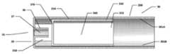
도 5a 및 도 5b는, 다시, 외부 하우징(200) 및 내부 용기(350)를 포함하는 카트리지(30)의 일 구현을 예시한다. 특히, 도 5a는 (길이 방향 축(LA)을 포함하는) 카트리지(30)에 걸친 수평 단면인 한편, 도 5b는 내부 용기(350) 단독(즉, 외부 하우징(200)의 내부측으로부터 제거된) 도면이다.5A and 5B, again, illustrate one implementation of a
도 5a 및 도 5b의 구현은 래칭 기구(500)를 포함하는 것이 도 3a, 도 3b 및 도 4의 카트리지와 상이하다. 이러한 래칭 기구는 내부 용기(350)에서 형성되는 그루브(510) 및 외부 하우징(200)의 내부측 상에 형성되는 상응하는 돌기(505)를 제공함으로써 형성된다. 도 5b에서 알 수 있는 바와 같이, 그루브(510)는, 그루브가 최상부 벽(356)을 가로질러 연장하지 않는 것을 제외하고, (길이 방향 축에 대해) 내부 용기의 원주 둘레에서 연장한다. 그루브는 숫자 "7"과 다소 유사한 형상을 가지고, 2 개의 측들로 형성된다. 제 1 측은 마우스피스(35)로부터 가장 멀리 로케이팅되고 길이 방향 축(LA)에 대해 그리고 내부 용기(350)의 외부 원통형 표면에 대해 상대적으로 섈로우 각도(shallow angle) 또는 구배(gradient)를 가진다. 제 2 측은 마우스피스(35)에 더 가깝게 로케이팅되고, 길이 방향 축(LA)에 대해 매우 더 급격한(steeper)(잠재적으로 수직한) 각도 또는 구배를 가진다.The implementation of FIGS. 5A and 5B differs from the cartridge of FIGS. 3A, 3B and 4 in that it includes a
외부 하우징(200)의 내부측 상에 형성되는 돌기(505)는 그루브(510)에 대한 상호보완적 형상을 가진다. 특히, 돌기(505)는 외부 하우징(200)의 내부 벽의 원주 둘레에서 연장한다. 그러나, 돌기는 공기 통로(355)를 막지 않도록 외부 하우징(200)의 최상부 벽(301C)에 걸쳐 연장하지 않는다. 돌출부(505)는 또한 (그루브(510)와 정합하기 위해) 숫자 "7"과 다소 유사한 형상을 가지고, 2 개의 측들로 형성된다. 제 1 측은 마우스피스(35)로부터 가장 멀리 로케이팅되고 길이 방향 축(LA)에 대해 그리고 외부 하우징(200)의 내부 원통형 표면에 대해 상대적으로 섈로우 각도 또는 구배를 가진다. 제 2 측은 마우스피스(35)에 더 가깝게 로케이팅되고, 길이 방향 축(LA)에 대해 매우 더 급격한(잠재적으로 수직한) 각도 또는 구배를 가진다.The
일단 내부 용기(350)가 도 5에서 도시되는 구현에 따라 외부 하우징(200) 내로 삽입된다면, 돌기(505)의 급격한 제 2 측은 그루브(510)의 급격한 제 2 측에 맞닿아 접해 있는 것이 이해될 것이다. 이러한 접함(abutment)은 길이 방향 축을 따른, 특히 마우스피스(35)로부터 가장 멀리 있는 외부 하우징(200)의 단부를 향하여 내부 용기를 이동시키는 경향이 있는 방향으로 내부 용기(350)와 외부 하우징(200) 사이의 이동을 방지한다.Once the
도 6a 및 도 6b는 외부 하우징(200) 및 내부 용기(350)를 다시 포함하는 카트리지(30)의 다른 구현을 예시한다. 특히, 도 6a은 길이 방향 축(LA)을 포함하는 카트리지(30)를 통과하는 수평 단면인 반면에, 도 6b는 (즉, 외부 하우징(200)의 내부측으로부터 제거된 바와 같은) 내부 용기(350) 그 자체의 도면이다.6A and 6B illustrate another implementation of the
도 6a 및 도 6b의 구현은 도 5a 및 도 5b의 구현과 유사하다. 차이는 도 5a 및 도 5b의 구현에서, 내부 용기(350)의 벽의 내부 면이 카트리지의 길이 방향 길이를 따라 평탄하였던 점이다. 결과적으로, 그루브(510)가 형성되는 내부 용기(350)의 벽의 부분은 보다 얇고, 이에 의해 이러한 벽의 나머지보다 잠재적으로 더 약하다. 도 6a 및 도 6b의 구현에서, 그러나, 내부 용기의 벽(605)은, 사실상, 대략적으로 일정한 두께를 가진다. 이는, 그루브(510)의 만입부(indentation)가 내부 용기의 내부 체적 내로 내부 용기의 벽(605)의 상응하는 만입부(610)에 의해 경면대칭되는(mirrored) 것을 의미한다.The implementations of FIGS. 6A and 6B are similar to the implementations of FIGS. 5A and 5B. The difference is that in the implementation of FIGS. 5A and 5B, the inner face of the wall of the
도 6a 및 도 6b의 구현에서의 래칭 기구(500)의 작동은 도 5a 및 도 5b의 구현에서의 래칭 기구(500)의 작동과 실질적으로 유사한 것이 이해될 것이다. 그러나, 도 6a 및 도 6b의 구현은 내부 용기(350)의 벽(605)을 위한 감소된 두께를 가지는 것을 회피하며, 이는 일부 상황들에 대해 중요할 수 있다.It will be appreciated that the operation of the
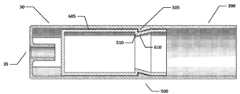
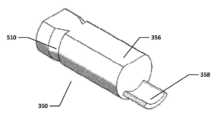
도 7a 및 도 7b는 외부 하우징(200) 및 내부 용기(350)를 다시 포함하는 카트리지(30)의 다른 구현을 예시한다. 특히, 도 7a은 길이 방향 축(LA)을 포함하는 카트리지(30)를 통과하는 수직 단면인 반면에, 도 7b는 (즉, 외부 하우징(200)의 내부측으로부터 제거된 바와 같은) 내부 용기(350) 그 자체, 특히 마우스 단부(35)에 인접한 부분의 도면이다.7A and 7B illustrate another implementation of the
도 7a 및 도 7b의 구현에서, 외부 하우징(200)은, 돌기(705)의 추가를 제외하면, 도 3a, 도 3b 및 도 4의 구현에 대한 것과 일반적으로 동일하다. 이러한 돌기는 외부 하우징(200)의 마우스피스 단부 가까이에, 특히 내부 용기의 단부 벽(370)과 외부 하우징의 단부 벽(39) 사이에 로케이팅된다. 돌기(705)는 직접적으로 반경 방향으로 내부측을 향하고, 외부 하우징(200)의 내부 원주 모든 둘레에 형성되며, 즉 돌기는 길이 방향 축(LA)에 대해 0 내지 360도의 방위각들로 가로지른다.In the implementation of FIGS. 7A and 7B, the
돌기(705)는 다시 숫자 "7"과 다소 유사한 형상을 가지고, 2 개의 측들로 형성된다. 제 1 측(램프 부분)은 마우스피스 단부(35)로부터 가장 멀리 로케이팅되고 길이 방향 축(LA)에 대해 그리고 또한 외부 하우징(200)의 내부 원통형 표면에 대해 상대적으로 섈로우 각도 또는 구배를 가진다. 제 2 측(캐치 부분)은 마우스피스(35)에 더 가깝게 로케이팅되고, 길이 방향 축(LA)에 대해 매우 더 급격한(잠재적으로 수직한) 각도 또는 구배를 가진다.The
도 7a 및 도 7b의 구현에서, 내부 용기(350)는, 제 2 탭(750)의 추가를 제외하면, 도 3a, 도 3b 및 도 4의 구현에 대한 것과 일반적으로 동일하다. 이러한 제 2 탭(750)은, 제 2 탭이 벽(370)으로부터 마우스피스 단부(35)를 향하여 연장하는 점에서, 제 1 탭과 같다. 그러나, 제 2 탭은 제 1 탭보다 다소 더 짧아서, 제 2 탭은 외부 하우징(200)의 단부 벽(39)에 도달하지 않는다. 또한, 제 2 탭(750)은 내부 용기의 최상부 벽(356)으로부터 연장하고, 따라서 (길이 방향 축(LA)을 고려하여) 내부 용기(350)의 저부에 가까운 곳으로부터 연장하는 제 1 탭(358)에 정반대이다(diametrically opposed).In the implementations of FIGS. 7A and 7B, the
제 2 탭(750)은 또한 제 1 탭(358)으로부터 상이하게 성형된다. 따라서, 제 2 탭(750)은 평탄하고 단부 벽(370)에 부착되는 제 1 부분을 포함한다. 이러한 평탄한 부분은, 실제로, 최상부 벽(356)의 연장부로서 고려될 수 있다. 평탄 부분은 또한, 캔틸레버 유형으로 상승된 부분(755)을 지지한다. 이러한 상승된 부분(755)은 래칭 기구(500)를 형성하기 위해 외부 하우징(200)의 돌기(705)와 상호작용한다. 그러나, 외부 하우징의 돌기(705)가 돌기(705)의 반경 방향으로 내향으로 지날 수 있는 제 1 탭(358)을 막지 않도록 크기가 정해지는 것을 주목해야 한다.The
상승된 부분(755)는 다시 숫자 "7"과 다소 유사한 형상을 가지고, 2 개의 측들로 형성된다. 제 1 측은 단부 벽(370)로부터 가장 멀리 로케이팅되고 길이 방향 축(LA)에 대해 그리고 또한 내부 용기(350)의 최상부 벽(356)에 대해 상대적으로 섈로우 각도 또는 구배를 가진다. 제 2 측은 마우스피스(35)에 더 가깝게 로케이팅되고, 길이 방향 축(LA)에 대해 매우 더 급격한(잠재적으로 수직한) 각도 또는 구배를 가진다.The raised
작동 시, 내부 용기가 외부 하우징(200) 내로 삽입됨에 따라, 제 2 탭(750)의 상승된 부분(755)이 외부 용기의 내향 돌기(705)와 접촉하는 것을 알 수 있다. 이는 제 2 탭(750)이 반경 방향으로의 내향(하향) 방향으로 약간 휘는(flex) 것을 유발시키며, 이에 의해 상승된 부분(755)이 내향 돌기(705)를 지나 (그리고 이 내향 돌기에 맞닿게) 미끄러지는 것을 허용한다.In operation, it can be seen that as the inner container is inserted into the
결국, 도 7a에서 도시되는 바와 같이, 내부 용기가 완전히 삽입될 때, 돌기(705)의 코너(즉, 섈로우 측이 급격한 측과 만나는 곳)는 상승된 부분(755)의 코너(다시, 섈로우 측이 급격한 측과 만나는 곳)를 지나간다. 이는 제 2 탭(750)이 도 7a에서 도시되는 포지션으로 상향으로 탄성적으로 역으로 휘는 것을 허용한다. 이러한 구성에서, 마우스 단부(35)의 방향으로 향하는 돌기(705)의 급격한 측은 반대 방향으로(마우스 단부로부터 멀어지게) 향하는 제 2 탭(750)의 상승된 부분(755)의 급격한 측에 맞닿게 접한다. 이러한 2 개의 측들은 래치 기구(500)를 위한 래칭 작용을 제공하기 위해 서로 맞닿게 접하고, 이에 의해 외부 하우징(200)으로부터 내부 용기(350)의 인출을 방지한다.As a result, as shown in FIG. 7A, when the inner container is fully inserted, the corner of the protrusion 705 (ie, where the fellow side meets the abrupt side) is the corner of the raised portion 755 (again, Where the low side meets the abrupt side). This allows the
길이 방향 축(LA)에 대해 대응하는 원주 방향의 (방위각의) 범위, 즉 회전 각도가 제 1 탭(358)에 대한 것보다 제 2 탭(750)에 대한 것이 더 작은 것을 주목해야 한다. 또한, 길이 방향 축(LA)에 대해 대응하는 회전 각도는 내부 용기의 최상부 벽(356)에 대한 것보다 제 2 탭(750)에 대한 것이 더 작다. 이는, 통로(355)를 따라 유동하는 공기(도 3b 참조)가 제 2 탭 둘레를, 즉 제 2 탭의 어느 하나의 측 상에서 유동할 수 있어, 마우스피스 홀(37)로 그리고 그 후 e-시가레트(10) 밖으로 진행하는 것을 보장한다.It should be noted that the corresponding circumferential (azimuth) range, ie the angle of rotation, relative to the longitudinal axis LA is smaller for the
도 7a 및 도 7b에서 도시되는 구현의 하나의 특정의 장점은, 내부 용기(350)를 외부 하우징(200) 내로 삽입하기 위해, 이러한 2 개의 컴포넌트들을 위한 2 개의 길이 방향 축들이 서로 정렬되어야(즉, 일치해야) 한다는 점이다. 그러나, 길이 방향 축(LA)을 중심으로 외부 하우징(200)에 대해 내부 용기(350)를 회전식으로 정렬할 필요는 없는데, 왜냐하면 외부 하우징의 내향 돌기(705)는 360도의 회전 각도만큼 가로지르기 때문이다. 이에 따라, 제 2 탭(750)은 외부 하우징(200)과 내부 용기(350) 사이의 삽입의 상대적인 회전 각도와 관계없이 내향 돌기와 맞물릴 것이다. 따라서, 이는 외부 하우징(200) 내로의 내부 용기(350)의 삽입 전에 이러한 2 개의 컴포넌트들 사이의 회전 정렬을 수행할 필요를 회피하며, 이는 제조 복잡성(그리고 이에 따라 비용들)을 감소시키는데 도움을 줄 수 있다.One particular advantage of the implementation shown in FIGS. 7A and 7B is that two longitudinal axes for these two components must be aligned with one another (ie, to insert the
도 7a 및 도 7b의 실시예는 내부 용기(350)에서 형성되는 그루브 부분을 가지는 것을 다시 회피하며, 이에 의해 임의의 잠재적인 취약(weakness)을 회피한다. 또한, 도 6의 실시예와 달리, 내부 용기의 내부 형상은 변하지 않는다. 이는 내부 용기(350)의 최대 체적을 유지하는 것뿐만 아니라, 충전 프로세스(filling process)에 의한 임의의 잠재적인 어려움들을 회피하는데 도움을 줄 수 있다.The embodiments of FIGS. 7A and 7B again avoid having groove portions formed in the
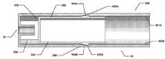
도 8a 및 도 8b는 외부 하우징(200) 및 내부 용기(350)를 다시 포함하는 카트리지(30)의 다른 구현을 예시한다. 특히, 도 8a는 (길이 방향 축(LA)을 포함하는) 카트리지(30)를 통한 수직 단면인 반면, 도 8b는 (즉, 외부 하우징(200) 내부측으로부터 제거되는 바와 같은) 그 자체로 내부 용기(350)의 도면이다.8A and 8B illustrate another implementation of the
도 8a 및 도 8b의 구현에서, 외부 하우징(200)은 돌기(805)의 추가를 제외하고, 도 3a, 도 3b 및 도 4의 구현에 대한 것과 일반적으로 동일하다. 이러한 돌기는, 그의 로케이션을 제외하고 도 7a 및 도 7b의 구현의 돌기(705)와 일반적으로 유사하다. 따라서, (내부 용기가 외부 하우징(200)으로 완전히 삽입되는 경우) 돌기(805)는 마우스 단부(35) 근처에 있는 것이 아니라 오히려, 마우스 단부(35)로부터 가장 먼 내부 용기(350)의 단부 근처에 있기 위해 로케이팅된다.In the implementations of FIGS. 8A and 8B, the
돌기(805)는 직접적으로 방사상 내향이고 숫자 "7"과 다소 유사한 형상을 다시 가지며, 양측들에 의해 형성된다. 제 1 측(램프 부분)은 마우스피스 단부(35)로부터 가장 멀리 로케이팅되며, 길이 방향 축(LA)에 대해 그리고 또한 외부 하우징(200)의 내부 원통형 표면에 대해 상대적 섈로우 각도 또는 구배를 갖는다. 제 2 측(캐치 부분)은 마우스피스(35)에 더 가깝게 로케이팅되며, 길이 방향 축(LA)에 대해 훨씬 더 급격한 (잠재적으로는 수직한) 각도 또는 구배를 갖는다.The
도 8a 및 도 8b의 구현에서, 내부 용기(350)는, 내부 용기의 최상부 벽(356) 상에 형성되고 방사상 외향으로 지향되는 돌기(850)의 추가를 제외하고, 도 3a, 도 3b 및 도 4의 구현에 대한 것과 일반적으로 동일하다. 돌기(850)는 숫자 "7"과 다소 유사한 형상을 다시 가지며, 양측들에 의해 형성된다. 제 1 측은 단부 벽(370)에 가장 가깝게 로케이팅되며, 길이 방향 축(LA)에 대해 그리고 또한 내부 용기(350)의 최상부 벽(356)에 대해 상대적 섈로우 각도 또는 구배(램프 부분)를 갖는다. 제 2 측은 단부 벽(370)으로부터 더 멀리 로케이팅되며, 길이 방향 축(LA)에 대해 훨씬 더 급격한 (잠재적으로는 수직한) 각도 또는 구배를 갖는다.In the implementation of FIGS. 8A and 8B, the
작동시, 내부 용기가 외부 하우징(200)으로 삽입될 때, 내부 용기(350) 상의 돌기(850)의 램프 부분은 외부 용기의 내향 돌기(805)의 대응하는 램프 부분과 접촉하게 된다. 결국, 내부 용기가 완전히 삽입되는 경우, 도 8a에 도시된 바와 같이, 마우스 단부(35)의 방향으로 대면하는 돌기(805)의 급격한 측은, (마우스 단부로부터 떨어져) 반대 방향으로 대면하는 내부 용기 돌기(850)의 급격한 측에 접한다. 이들 양측들은 래치 기구(500)에 대한 래칭 작용을 제공하기 위해 서로 접하며, 그에 의해, 외부 하우징(200)으로부터 내부 용기(350)의 인출을 방지한다.In operation, when the inner container is inserted into the
내부 용기(350)의 최상부 벽(356) 상의 돌기(850)의 폭이 최상부 벽(356)의 폭보다 작음을 주목한다. 이것은, 통로(355)(도 3b 참조)를 따라 흐르는 공기가 마우스피스 홀(37)로 그리고 그후에는 e-시가레트(10) 바깥으로 진행하기 위해 돌기(850) 주변, 즉 그의 어느 하나의 측 상에서 흐를 수 있다는 것을 보장한다.Note that the width of the
도 9a, 도 9b 및 도 9c는 외부 하우징(200) 및 내부 용기(350)를 다시 포함하는 카트리지(30)의 다른 구현을 예시한다. 특히, 도 9a는 (길이 방향 축(LA)을 포함하는) 카트리지(30)를 통한 수평 단면이고, 도 9b는 수직 평면을 분할된 (내부 용기(350) 없는) 외부 하우징(200)의 뷰이며, 도 9c는 (즉, 외부 하우징(200) 내부측으로부터 제거되는 바와 같은) 그 자체로 내부 용기(350)의 도면이다.9A, 9B and 9C illustrate another implementation of the
도 9a 내지 도 9c의 구현에서, 외부 하우징(200)은 외부 하우징의 내부 벽들에서의 원주방향 그루브(905)의 추가를 제외하고, 도 3a, 도 3b 및 도 4의 구현에 대한 것과 일반적으로 동일하다. 더 상세하게, 그루브(905)는 외부 하우징(200)의 내부 원주 주변에 모두 형성되며, 즉 그것은 길이 방향 축(LA)에 대해 0으로부터 360도까지의 방위 각도들에 걸쳐 있다. 그루브(905)는 숫자 "7"과 다소 유사한 형상을 다시 가지며, 양측들에 의해 형성된다. 제 1 측(램프 부분)은 마우스피스 단부(35)로부터 가장 멀리 로케이팅되며, 길이 방향 축(LA)에 대해 그리고 또한 외부 하우징(200)의 내부 원통형 표면에 대해 상대적 섈로우 각도 또는 구배를 갖는다. 제 2 측(캐치 부분)은 마우스피스(35)에 더 가깝게 로케이팅되며, 길이 방향 축(LA)에 대해 훨씬 더 급격한 (잠재적으로는 수직한) 각도 또는 구배를 갖는다.In the implementation of FIGS. 9A-9C, the
도 9a 내지 도 9c의 구현에서, 내부 용기(350)는, 내부 용기의 각각의 측벽 상에 형성되고 방사상 외향으로 지향되는 돌기(950A, 950B)의 추가를 제외하고, 도 3a, 도 3b 및 도 4의 구현에 대한 것과 일반적으로 동일하다. 돌기들(950A, 950B)은 숫자 "7"과 다소 유사한 형상을 다시 가지며, 양측들에 의해 각각 형성된다. 제 1 측은 단부 벽(370)에 가장 가깝게 로케이팅되며, 길이 방향 축(LA)에 대해 상대적 섈로우 각도 또는 구배(램프 부분)를 갖는다. 제 2 측은 단부 벽(370)으로부터 더 멀리 로케이팅되며, 길이 방향 축(LA)에 대해 훨씬 더 급격한 (잠재적으로는 수직한) 각도 또는 구배를 갖는다.In the implementation of FIGS. 9A-9C, the
작동시, 내부 용기가 외부 하우징(200)으로 삽입될 때, 내부 용기(350) 상의 돌기들(950A, 950B)의 램프 부분은 외부 용기(200)의 대응하는 내부 벽과 접촉하게 되며, 따라서, 이것은 외향으로 약간 구부러진다. 결국, 내부 용기가 완전히 삽입되는 경우, 도 9a에 도시된 바와 같이, 마우스 단부(35)으로부터 멀어지는 방향으로 대면하는 돌기들(950A, 950B)의 급격한 측들은, (마우스 단부를 향해) 반대 방향으로 대면하는 그루브(905)의 급격한 측에 접한다. 이들 양측들은 래치 기구(500)에 대한 래칭 작용을 제공하기 위해 그루브 로케이션들(905A, 905B)에서 서로 접하며, 그에 의해, 외부 하우징(200)으로부터 내부 용기(350)의 인출을 방지한다.In operation, when the inner container is inserted into the
도 9a 내지 도 9c에 도시된 구현의 하나의 특정의 장점은 다시, 외부 하우징의 내향 그루브(905)가 360도의 회전 각도에 걸쳐 있으므로, 길이 방향 축(LA)에 대한 외부 하우징(200)에 대해 내부 용기(350)를 회전가능하게 정렬시킬 필요가 없다는 것이다. 따라서, 외부 하우징(200)의 그루브(905)는, 외부 하우징(200)과 내부 용기(350) 사이의 삽입의 상대적 회전 각도와 관계없이 내부 용기의 돌기들(950A, 950B)과 맞물림될 것이다. 따라서, 이것은, 내부 용기(350)의 외부 하우징(200)으로의 삽입 이전에 이들 2개의 컴포넌트들들 사이에서 회전 정렬을 수행할 필요를 회피하고, 이는 제조 복잡성(및 그에 따른 비용들)을 감소시키는 것을 도울 수 있다.One particular advantage of the implementation shown in FIGS. 9A-9C is again that with respect to the
도 10은 외부 하우징(200) 및 내부 용기(350)를 다시 포함하는 카트리지(30)의 다른 구현을 예시한다. 특히, 도 10은 (길이 방향 축(LA)을 포함하는) 카트리지(30)를 통한 수평 단면이다. 도 10의 구현은, 원주방향 그루브(1005)가 외부 하우징(200)의 내부 원통형 벽 상에 형성된다는 점에서 도 9a 내지 도 9c의 구현과 일반적으로 동일하며, 이것은 내부 용기(350)의 각각의 측들 상의 2개의 대응하는 돌기들(1050A, 1050B)을 갖는 래칭 기구(500)를 형성한다.10 illustrates another implementation of the
도 10의 구현은, 길이 방향 축(LA)을 따른 원주방향 그루브(1005)의 포지셔닝 및 그에 따른 돌기들(1050A, 1050B)의 대응하는 포지셔닝에 대해 도 9a 내지 도 9c의 구현과 상이하다. 특히, 돌기들(1050A, 1050B)은 이제, (테일 핀들과 유사한) 마우스 단부(35)로부터 가장 멀리 내부 용기의 단부에 로케이팅된다. 이러한 포지셔닝은 특정의 장점들을 제공할 수 있다. 예컨대, 내부 용기(350)가 래칭 기구(500)의 맞물림 이전에 외부 하우징(200)으로 삽입될 때 돌기들(1050A, 1050B)을 수용하기 위한 외부 하우징의 휨은, 단부 벽(39) 및 마우스 단부(35)로부터 멀리 떨어져 그리고 외부 하우징(200)의 (반대쪽) 개방 단부에 더 근처에 있게 발생한다. 이러한 개방 단부가 당연히 약간 증가된 유연성을 갖을 것임이 인식될 것이다.The implementation of FIG. 10 differs from the implementation of FIGS. 9A-9C with respect to the positioning of the circumferential groove 1005 along the longitudinal axis LA and the corresponding positioning of the
다양한 래칭 기구들(500)이 본원에 개시되었지만, 이들은 예로서 제시되며, 래칭 기구의 형상, 포지셔닝, 작동 등에 대한 많은 추가적인 가능성들이 당업자들에게 명백할 것임이 인식될 것이다. 또한, 본원에 설명된 e-시가레트가 3개의 분리가능한 섹션들, 즉 제어 유닛, 카트리지 및 증발기를 포함하지만, 다른 e-시가레트들이 상이한 수의 섹션들을 포함할 수 있음이 인식될 것이다.While various latching
다양한 이슈를 다루고 기술을 발전시키기 위해, 본 개시는, 청구된 발명(들)이 실시될 수 있는 다양한 실시예들을 예시로써 도시한다. 본 개시의 장점들 및 특성들은 단지 실시예들의 대표적인 샘플이며, 포괄적인 및/또는 배타적인 것이 아니다. 그들은 단지, 청구된 발명(들)을 이해하는 것을 보조하고 교시하기 위해 제시된다. 본 개시의 장점들, 실시예들, 예들, 기능들, 특성들, 구조들, 및/또는 다른 양태들은 청구항에 의해 정의된 바와 같은 개시에 대한 제한들 또는 청구항들의 등가물들에 대한 제한들로 고려되지 않으며, 청구항들의 범위를 벗어나지 않으면서 다른 실시예들이 이용될 수 있고 변형들이 행해질 수 있음이 이해될 것이다. 다양한 실시예들은 본원에 구체적으로 설명된 것들 이외의 개시된 엘리먼트들, 컴포넌트들, 피처들, 부품들, 단계들, 수단들 등의 다양한 조합들을 적절하게 포함하거나, 그들로 구성하거나, 그들로 본질적으로 구성될 수 있다. 본 개시는 현재 청구되지는 않았으나 추후에 청구될 수 있는 다른 발명들을 포함할 수 있다.To address various issues and advance the technology, the present disclosure illustrates by way of example various embodiments in which the claimed invention (s) may be practiced. The advantages and features of the present disclosure are merely representative samples of embodiments and are not exhaustive and / or exclusive. They are presented only to assist and teach the understanding of the claimed invention (s). Advantages, embodiments, examples, functions, features, structures, and / or other aspects of the disclosure are considered to be limitations on the disclosure as defined by the claims or equivalents to the claims. It is to be understood that other embodiments may be utilized and modifications may be made without departing from the scope of the claims. Various embodiments suitably include, consist of, or essentially include various combinations of the disclosed elements, components, features, parts, steps, means, etc., other than those specifically described herein. Can be configured. The present disclosure may include other inventions that are not currently claimed but may be claimed later.
Claims (20)
Translated fromKorean상기 카트리지는 증발될 유체의 리저보어(reservoir)를 유지하는 내부 용기 및 마우스피스(mouthpiece)가 내부에 형성되는 외부 하우징을 포함하고, 상기 외부 하우징은, 상기 내부 용기의 상당 부분(substantial portion)에 대해, 상기 내부 용기의 외부측을 따라서 길이 방향으로 연장하고, 그리고 상기 내부 용기 및 외부 하우징에는 상기 내부 용기를 상기 외부 하우징 내에 보유하기 위해 래치 기구(latch mechanism)가 제공되는,
카트리지.A cartridge for use in a vapor delivery system,
The cartridge includes an inner container for holding a reservoir of fluid to be evaporated and an outer housing formed therein with a mouthpiece, the outer housing having a substantial portion of the inner container. With respect to the outer side of the inner container, the inner container and the outer housing being provided with a latch mechanism for retaining the inner container in the outer housing.
cartridge.
상기 래치 기구는 상기 길이 방향 축에 대하여 상기 내부 용기와 상기 외부 하우징 사이의 상대 회전 각도와 독립적으로 작동 가능한,
카트리지.The method of claim 1,
The latch mechanism is operable independently of the relative angle of rotation between the inner container and the outer housing about the longitudinal axis;
cartridge.
상기 래치 기구는 상기 외부 하우징 또는 상기 내부 용기 중 하나에 형성되는 제 1 부재, 및 상기 외부 하우징 또는 상기 내부 용기 중 다른 하나에 형성되는 협동하는 제 2 부재를 포함하며, 상기 제 1 및 제 2 부재들은 상기 래치 기구와 맞물리도록 서로 접하는,
카트리지.The method according to claim 1 or 2,
The latch mechanism includes a first member formed in one of the outer housing or the inner container, and a cooperating second member formed in the other of the outer housing or the inner container, the first and second members Are in contact with each other to engage the latch mechanism,
cartridge.
상기 제 1 및 제 2 부재들은 상기 마우스피스의 로케이션에 대해 길이 방향으로 대향하는 상기 내부 용기의 단부에 또는 상기 내부 용기의 단부 부근에 로케이팅되는,
카트리지.The method of claim 3, wherein
Wherein the first and second members are located at or near an end of the inner container which is longitudinally opposite to the location of the mouthpiece,
cartridge.
상기 내부 용기는 상기 유체의 리저보어를 유지하는 본체 및 탭(tab)을 포함하며, 상기 탭은 상기 본체를 상기 마우스피스로부터 분리하여 상기 마우스피스를 통한 기류를 허용하고, 상기 제 1 및 제 2 부재들은 상기 탭에 인접하게 길이 방향으로 로케이팅되는,
카트리지.The method of claim 3, wherein
The inner container includes a body and a tab for holding the reservoir of the fluid, the tab separating the body from the mouthpiece to allow airflow through the mouthpiece, and the first and second The members are located longitudinally adjacent the tab,
cartridge.
상기 제 1 부재는 상기 외부 하우징의 내부 표면에 방사상으로 지향된 그루브(groove)를 포함하고, 상기 제 2 부재는 상기 내부 용기의 외부 표면 상에 적어도 하나의 방사상으로 지향된 돌기(protrusion)를 포함하는,
카트리지.The method according to any one of claims 3 to 5,
The first member includes a groove directed radially to the inner surface of the outer housing, and the second member includes at least one radially directed protrusion on the outer surface of the inner container. doing,
cartridge.
상기 제 1 부재는 상기 외부 하우징의 내부 표면으로부터 방사상으로 지향된 돌기를 포함하고, 상기 제 2 부재는 상기 내부 용기의 외부 표면 상에 적어도 하나의 방사상으로 지향된 그루브를 포함하는,
카트리지.The method according to any one of claims 3 to 5,
The first member includes a projection directed radially from the inner surface of the outer housing, and the second member includes at least one radially directed groove on the outer surface of the inner container;
cartridge.
상기 제 1 부재는 상기 외부 하우징의 내부 표면으로부터 방사상으로 지향된 돌기를 포함하고, 상기 제 2 부재는 상기 내부 용기의 외부 표면 상에 적어도 하나의 방사상으로 지향된 돌기를 포함하는,
카트리지.The method according to any one of claims 3 to 5,
The first member includes a projection directed radially from the inner surface of the outer housing, and the second member includes at least one radially directed projection on the outer surface of the inner container;
cartridge.
상기 제 1 또는 제 2 부재들 중 적어도 하나는 상기 길이 방향으로 연장하는 축을 중심으로 원주 방향으로 연장되는,
카트리지.The method according to any one of claims 3 to 8,
At least one of the first or second members extends circumferentially about an axis extending in the longitudinal direction,
cartridge.
상기 제 1 및 제 2 부재들에는, 상기 내부 용기가 상기 래치의 맞물림 이전에 상기 외부 하우징 내로 삽입됨에 따라 서로 지나서 미끄러지는 램프 부분들(ramp portions)이 제공되는,
카트리지.The method according to any one of claims 3 to 9,
The first and second members are provided with ramp portions that slide past each other as the inner container is inserted into the outer housing prior to engagement of the latch,
cartridge.
상기 외부 하우징의 내부 표면과 상기 내부 용기의 외부 표면 사이에 채널(channel)이 제공되어 증기가 채널을 통해 마우스피스로 길이 방향으로 유동하는 것을 허용하는,
카트리지.The method according to any one of claims 1 to 10,
A channel is provided between the inner surface of the outer housing and the outer surface of the inner container to allow vapor to flow longitudinally through the channel into the mouthpiece,
cartridge.
상기 외부 하우징은 상기 길이 방향으로 연장하는 축에 대해 실질적으로 원형 단면을 가지며, 상기 내부 용기는 상기 채널을 제공하기 위해 상기 길이 방향 축에 대해 실질적으로 D형 단면을 갖는,
카트리지.The method of claim 11,
The outer housing has a substantially circular cross section about an axis extending in the longitudinal direction, and the inner container has a substantially D-shaped cross section about the longitudinal axis to provide the channel;
cartridge.
상기 래치 기구는 상기 채널 내에 로케이팅되고, 상기 채널을 차단하지 않도록 크기가 정해지는,
카트리지.The method according to claim 11 or 12,
The latch mechanism is located within the channel and sized to not block the channel,
cartridge.
상기 외부 하우징 및 상기 내부 용기 중 적어도 하나는 상기 래치 기구의 작동을 지지하기에 충분히 가요적으로 탄성이 있는(flexibly resilient),
카트리지.The method according to any one of claims 1 to 13,
At least one of the outer housing and the inner container is flexibly resilient flexible enough to support operation of the latch mechanism,
cartridge.
상기 외부 하우징은 증기 제공 시스템의 제어 유닛에 상기 카트리지를 길이 방향으로 부착하기 위한 기계적 커넥터를 포함하는,
카트리지.The method according to any one of claims 1 to 14,
The outer housing includes a mechanical connector for longitudinally attaching the cartridge to a control unit of a vapor providing system,
cartridge.
상기 카트리지는 증발기를 포함하는,
카트리지.The method of claim 15,
The cartridge comprises an evaporator,
cartridge.
상기 기계적 커넥터는 상기 증발기를 작동시키기 위해 상기 제어 유닛으로부터 전력을 수신하기 위한 전기 연결부를 더 제공하는,
카트리지.The method of claim 16,
The mechanical connector further provides an electrical connection for receiving power from the control unit to operate the evaporator,
cartridge.
Priority Applications (1)
| Application Number | Priority Date | Filing Date | Title |
|---|---|---|---|
| KR1020217031796AKR102581948B1 (en) | 2015-01-22 | 2016-01-21 | Vapour provision system and cartridge therefor |
Applications Claiming Priority (4)
| Application Number | Priority Date | Filing Date | Title |
|---|---|---|---|
| GBGB1501060.6AGB201501060D0 (en) | 2015-01-22 | 2015-01-22 | Vapour provision system and cartridge therefor |
| GB1501060.6 | 2015-01-22 | ||
| PCT/GB2016/050126WO2016116754A1 (en) | 2015-01-22 | 2016-01-21 | Vapour provision system and cartridge therefor |
| KR1020177020533AKR102034790B1 (en) | 2015-01-22 | 2016-01-21 | Vapor Delivery System and Cartridges for the Same |
Related Parent Applications (1)
| Application Number | Title | Priority Date | Filing Date |
|---|---|---|---|
| KR1020177020533ADivisionKR102034790B1 (en) | 2015-01-22 | 2016-01-21 | Vapor Delivery System and Cartridges for the Same |
Related Child Applications (1)
| Application Number | Title | Priority Date | Filing Date |
|---|---|---|---|
| KR1020217031796ADivisionKR102581948B1 (en) | 2015-01-22 | 2016-01-21 | Vapour provision system and cartridge therefor |
Publications (2)
| Publication Number | Publication Date |
|---|---|
| KR20190119682Atrue KR20190119682A (en) | 2019-10-22 |
| KR102311621B1 KR102311621B1 (en) | 2021-10-08 |
Family
ID=52673777
Family Applications (3)
| Application Number | Title | Priority Date | Filing Date |
|---|---|---|---|
| KR1020177020533AActiveKR102034790B1 (en) | 2015-01-22 | 2016-01-21 | Vapor Delivery System and Cartridges for the Same |
| KR1020217031796AActiveKR102581948B1 (en) | 2015-01-22 | 2016-01-21 | Vapour provision system and cartridge therefor |
| KR1020197030281AActiveKR102311621B1 (en) | 2015-01-22 | 2016-01-21 | Vapour provision system and cartridge therefor |
Family Applications Before (2)
| Application Number | Title | Priority Date | Filing Date |
|---|---|---|---|
| KR1020177020533AActiveKR102034790B1 (en) | 2015-01-22 | 2016-01-21 | Vapor Delivery System and Cartridges for the Same |
| KR1020217031796AActiveKR102581948B1 (en) | 2015-01-22 | 2016-01-21 | Vapour provision system and cartridge therefor |
Country Status (17)
| Country | Link |
|---|---|
| US (2) | US10517327B2 (en) |
| EP (2) | EP3524073A3 (en) |
| JP (3) | JP6553195B2 (en) |
| KR (3) | KR102034790B1 (en) |
| CN (2) | CN107205492A (en) |
| BR (1) | BR112017015759B1 (en) |
| CA (1) | CA2973654C (en) |
| DE (3) | DE202016008830U1 (en) |
| ES (1) | ES2733803T3 (en) |
| GB (1) | GB201501060D0 (en) |
| HK (1) | HK1246607B (en) |
| MY (1) | MY188741A (en) |
| PH (1) | PH12017501324A1 (en) |
| PL (1) | PL3247233T3 (en) |
| RU (1) | RU2665451C1 (en) |
| UA (1) | UA123539C2 (en) |
| WO (1) | WO2016116754A1 (en) |
Families Citing this family (45)
| Publication number | Priority date | Publication date | Assignee | Title |
|---|---|---|---|---|
| US20160345631A1 (en) | 2005-07-19 | 2016-12-01 | James Monsees | Portable devices for generating an inhalable vapor |
| US10279934B2 (en) | 2013-03-15 | 2019-05-07 | Juul Labs, Inc. | Fillable vaporizer cartridge and method of filling |
| DE202014011260U1 (en) | 2013-12-23 | 2018-11-13 | Juul Labs Uk Holdco Limited | Systems for an evaporation device |
| USD842536S1 (en) | 2016-07-28 | 2019-03-05 | Juul Labs, Inc. | Vaporizer cartridge |
| USD825102S1 (en) | 2016-07-28 | 2018-08-07 | Juul Labs, Inc. | Vaporizer device with cartridge |
| US20160366947A1 (en) | 2013-12-23 | 2016-12-22 | James Monsees | Vaporizer apparatus |
| US10159282B2 (en) | 2013-12-23 | 2018-12-25 | Juul Labs, Inc. | Cartridge for use with a vaporizer device |
| US10058129B2 (en) | 2013-12-23 | 2018-08-28 | Juul Labs, Inc. | Vaporization device systems and methods |
| US10076139B2 (en) | 2013-12-23 | 2018-09-18 | Juul Labs, Inc. | Vaporizer apparatus |
| MX394125B (en) | 2014-12-05 | 2025-03-24 | Juul Labs Inc | CALIBRATED DOSE CONTROL |
| GB201501060D0 (en)* | 2015-01-22 | 2015-03-11 | Nicoventures Holdings Ltd | Vapour provision system and cartridge therefor |
| EP3135139B1 (en)* | 2015-08-28 | 2024-04-10 | Fontem Ventures B.V. | Electronic smoking device with integrated mouthpiece and capsule assembly |
| CO2018009342A2 (en) | 2016-02-11 | 2018-09-20 | Juul Labs Inc | Secure fixing cartridges for vaporizing devices |
| EP3413960B1 (en) | 2016-02-11 | 2021-03-31 | Juul Labs, Inc. | Fillable vaporizer cartridge and method of filling |
| US10455863B2 (en)* | 2016-03-03 | 2019-10-29 | Altria Client Services Llc | Cartridge for electronic vaping device |
| US10433580B2 (en) | 2016-03-03 | 2019-10-08 | Altria Client Services Llc | Methods to add menthol, botanic materials, and/or non-botanic materials to a cartridge, and/or an electronic vaping device including the cartridge |
| US10368580B2 (en) | 2016-03-08 | 2019-08-06 | Altria Client Services Llc | Combined cartridge for electronic vaping device |
| US10405582B2 (en) | 2016-03-10 | 2019-09-10 | Pax Labs, Inc. | Vaporization device with lip sensing |
| US10357060B2 (en) | 2016-03-11 | 2019-07-23 | Altria Client Services Llc | E-vaping device cartridge holder |
| US10368581B2 (en) | 2016-03-11 | 2019-08-06 | Altria Client Services Llc | Multiple dispersion generator e-vaping device |
| WO2017185051A1 (en) | 2016-04-22 | 2017-10-26 | Pax Labs, Inc. | Aerosol devices having compartmentalized materials |
| USD849996S1 (en) | 2016-06-16 | 2019-05-28 | Pax Labs, Inc. | Vaporizer cartridge |
| USD851830S1 (en) | 2016-06-23 | 2019-06-18 | Pax Labs, Inc. | Combined vaporizer tamp and pick tool |
| USD836541S1 (en) | 2016-06-23 | 2018-12-25 | Pax Labs, Inc. | Charging device |
| US10383367B2 (en) | 2016-07-25 | 2019-08-20 | Fontem Holdings 1 B.V. | Electronic cigarette power supply portion |
| IT201600084349A1 (en)* | 2016-08-10 | 2018-02-10 | Smart Evolution Trading S P A | PALM TREATMENT SYSTEM FOR PERSONAL USE, IN PARTICULAR AN ELECTRONIC CIGARETTE SYSTEM |
| WO2018114441A1 (en) | 2016-12-19 | 2018-06-28 | Philip Morris Products S.A. | An aerosol-generating system comprising multiple aerosol-forming substrates and a piercing element |
| US11045615B2 (en) | 2016-12-19 | 2021-06-29 | Altria Client Services Llc | Vapor-generating systems |
| GB201709201D0 (en)* | 2017-06-09 | 2017-07-26 | Nicoventures Holdings Ltd | Electronic aerosol provision system |
| USD887632S1 (en) | 2017-09-14 | 2020-06-16 | Pax Labs, Inc. | Vaporizer cartridge |
| JP7285856B2 (en) | 2018-04-24 | 2023-06-02 | ジェイティー インターナショナル エス.エイ. | Electronic cigarette with optimized vaporization |
| US11918045B2 (en) | 2018-04-24 | 2024-03-05 | Jt International S.A. | Electronic cigarette with optimised vaporisation |
| WO2019243612A1 (en)* | 2018-06-21 | 2019-12-26 | Philip Morris Products S.A. | Resealable cartridge assembly for an aerosol-generating system |
| CN116898146A (en)* | 2018-06-27 | 2023-10-20 | 尤尔实验室有限公司 | Evaporator device |
| US10888125B2 (en) | 2018-06-27 | 2021-01-12 | Juul Labs, Inc. | Vaporizer device with subassemblies |
| CN119632302A (en) | 2018-07-31 | 2025-03-18 | 尤尔实验室有限公司 | Cartridge-based heat-without-burn vaporizer |
| JP7502015B2 (en) | 2018-11-08 | 2024-06-18 | ジュール・ラブズ・インコーポレイテッド | Vaporizer device with one or more heating elements |
| US11445759B2 (en) | 2018-11-20 | 2022-09-20 | Altria Client Services Llc | E-vaping device |
| US11311049B2 (en) | 2018-11-20 | 2022-04-26 | Altria Client Services Llc | Air intake assembly |
| GB201912477D0 (en) | 2019-08-30 | 2019-10-16 | Nicoventures Trading Ltd | Aerosol provision systems |
| US20230256441A1 (en)* | 2020-08-26 | 2023-08-17 | Sense Biodetection Limited | Devices |
| US11690400B2 (en) | 2020-08-28 | 2023-07-04 | E-Cone LLC | Self-igniting cap for a pipe |
| KR102490572B1 (en) | 2020-09-23 | 2023-01-19 | 주식회사 케이티앤지 | Aerosol generating apparatus |
| DE102023127959A1 (en)* | 2023-10-12 | 2025-04-17 | Hakan Koca | E-cigarette with noise module |
| CN117918593A (en)* | 2024-03-07 | 2024-04-26 | 深圳市吉迩科技有限公司 | Atomizer and assembly method thereof and aerosol generating device |
Citations (4)
| Publication number | Priority date | Publication date | Assignee | Title |
|---|---|---|---|---|
| WO2009155734A1 (en)* | 2008-06-27 | 2009-12-30 | Maas Bernard | A substitute cigarette |
| JP2010099458A (en)* | 2008-09-24 | 2010-05-06 | Canon Inc | Liquid medicine container, and inhalation liquid medicine delivery device |
| WO2014060267A2 (en)* | 2012-10-19 | 2014-04-24 | Nicoventures Holdings Limited | Electronic vapour provision device |
| US20150305409A1 (en)* | 2013-11-12 | 2015-10-29 | VMR Products, LLC | Vaporizer |
Family Cites Families (41)
| Publication number | Priority date | Publication date | Assignee | Title |
|---|---|---|---|---|
| US2968307A (en) | 1955-12-21 | 1961-01-17 | Filtox S A | Cigarette or cigar holder |
| US3515146A (en) | 1967-06-27 | 1970-06-02 | Raymond N Nealis | Aromatic filter |
| EP0235736B1 (en) | 1986-03-06 | 1991-05-15 | Carlo Lugli | Improved mouth-piece for filtering the smoke of cigarettes and the like |
| US5167242A (en) | 1990-06-08 | 1992-12-01 | Kabi Pharmacia Aktiebolaq | Nicotine-impermeable container and method of fabricating the same |
| US5470257A (en)* | 1994-09-12 | 1995-11-28 | John Mezzalingua Assoc. Inc. | Radial compression type coaxial cable end connector |
| ES2363333T3 (en) | 2001-11-14 | 2011-08-01 | Novartis Ag | AEROSOL SPRAYING DEVICE INCLUDING A CONNECTABLE BODY AND TERMINAL PIECE. |
| CN100381083C (en) | 2003-04-29 | 2008-04-16 | 韩力 | Non-combustible electronic spray cigarette |
| CN2719043Y (en) | 2004-04-14 | 2005-08-24 | 韩力 | Atomized electronic cigarette |
| DE202006001663U1 (en) | 2006-02-03 | 2006-04-27 | Kieslich, Dirk | Smoke-free cigarette with nicotine and flavor cushions but without harmful combustion substances and side effects |
| US8042550B2 (en) | 2006-11-02 | 2011-10-25 | Vladimir Nikolaevich Urtsev | Smoke-simulating pipe |
| ATE418276T1 (en) | 2007-01-19 | 2009-01-15 | Grischa Plast Ag | SMOKELESS CIGARETTE, CIGARILLO, CIGAR OR THE LIKE. |
| EP1972215A1 (en) | 2007-03-20 | 2008-09-24 | Wedegree GmbH | Smoke-free cigarette substitute |
| US20090014212A1 (en)* | 2007-07-13 | 2009-01-15 | Malak Stephen P | Micro encapsulation seal for coaxial cable connectors and method of use thereof |
| CA2709071C (en) | 2007-12-14 | 2016-11-15 | Labogroup S.A.S. | Delivering aerosolizable food products |
| US8991402B2 (en) | 2007-12-18 | 2015-03-31 | Pax Labs, Inc. | Aerosol devices and methods for inhaling a substance and uses thereof |
| EP2370209A2 (en)* | 2008-12-03 | 2011-10-05 | Le Labogroup SAS | Delivering aerosolizable food products |
| CN201319860Y (en) | 2008-12-25 | 2009-10-07 | 中国科学院理化技术研究所 | Electronic cigarette adopting capacitor for power supply |
| DK2456329T3 (en) | 2009-07-22 | 2013-07-15 | Philip Morris Prod | Smoke-free cigarette replacement product |
| CA2789362C (en) | 2010-02-24 | 2014-05-27 | Japan Tobacco Inc. | Flavor inhalation pipe |
| CN101843368A (en)* | 2010-04-02 | 2010-09-29 | 陈志平 | Suction nozzle of electronic atomizer |
| US8689786B2 (en) | 2010-05-25 | 2014-04-08 | British American Tobacco (Investments) Limited | Aerosol generator |
| CA2807331C (en) | 2010-08-20 | 2015-05-19 | Japan Tobacco Inc. | Tobacco-flavor-releasing material and non-heating type tobacco flavor inhalator containing same |
| EA019736B1 (en)* | 2010-12-01 | 2014-05-30 | Евгений Иванович Евсюков | Inhaling device |
| CN201888252U (en)* | 2010-12-07 | 2011-07-06 | 罗青 | Electronic cigarette with filtering function |
| RU103281U1 (en)* | 2010-12-27 | 2011-04-10 | Общество с ограниченной ответственностью "ПромКапитал" | ELECTRONIC CIGARETTE |
| CN202005248U (en) | 2011-01-21 | 2011-10-12 | 万利龙 | Electronic atomization device capable substituting cigarette |
| DE102011010532A1 (en) | 2011-02-07 | 2012-08-09 | S.A.S.C. Ag | inhalator |
| CN202068930U (en) | 2011-03-18 | 2011-12-14 | 万利龙 | Filter cigarette holder and electronic cigarette device comprising same |
| WO2012155058A1 (en) | 2011-05-11 | 2012-11-15 | Breathable Foods, Inc. | Aerosol delivery apparatus |
| US20120312313A1 (en) | 2011-06-07 | 2012-12-13 | Vapor Corp. | Padded cartridge for an electronic smoking apparatus |
| KR102059699B1 (en) | 2011-07-13 | 2019-12-26 | 파맥시스 엘티디 | Improvements relating to delivery devices |
| AU2012342570B2 (en) | 2011-11-21 | 2016-11-24 | Philip Morris Products S.A. | Ejector for an aerosol-generating device |
| CN103826480A (en)* | 2012-01-24 | 2014-05-28 | 中汇远东实业有限公司 | An electronic simulated cigarette and its simulated mouthpiece |
| US8815174B2 (en)* | 2012-08-17 | 2014-08-26 | American Sterilizer Company | Steam sterilizer |
| US8910639B2 (en)* | 2012-09-05 | 2014-12-16 | R. J. Reynolds Tobacco Company | Single-use connector and cartridge for a smoking article and related method |
| US9423152B2 (en) | 2013-03-15 | 2016-08-23 | R. J. Reynolds Tobacco Company | Heating control arrangement for an electronic smoking article and associated system and method |
| CN103300480B (en) | 2013-06-06 | 2015-05-13 | 深圳市康尔科技有限公司 | Leak-proof atomizer |
| ITMO20130192A1 (en) | 2013-06-28 | 2014-12-29 | Damco S R L | KIT FOR ELECTRONIC CIGARETTES |
| CN103462224B (en) | 2013-08-31 | 2015-10-14 | 卓尔悦(常州)电子科技有限公司 | Electronic smoke atomizer |
| CN103720055A (en)* | 2013-12-13 | 2014-04-16 | 深圳市合元科技有限公司 | Electronic cigarette and atomizing device and power supply device and charging connector thereof |
| GB201501060D0 (en)* | 2015-01-22 | 2015-03-11 | Nicoventures Holdings Ltd | Vapour provision system and cartridge therefor |
- 2015
- 2015-01-22GBGBGB1501060.6Apatent/GB201501060D0/ennot_activeCeased
- 2016
- 2016-01-21DEDE202016008830.1Upatent/DE202016008830U1/enactiveActive
- 2016-01-21KRKR1020177020533Apatent/KR102034790B1/enactiveActive
- 2016-01-21EPEP19165920.0Apatent/EP3524073A3/enactivePending
- 2016-01-21DEDE202016008832.8Upatent/DE202016008832U1/enactiveActive
- 2016-01-21KRKR1020217031796Apatent/KR102581948B1/enactiveActive
- 2016-01-21EPEP16701857.1Apatent/EP3247233B1/enactiveActive
- 2016-01-21ESES16701857Tpatent/ES2733803T3/enactiveActive
- 2016-01-21JPJP2017538605Apatent/JP6553195B2/enactiveActive
- 2016-01-21DEDE202016008829.8Upatent/DE202016008829U1/enactiveActive
- 2016-01-21UAUAA201707716Apatent/UA123539C2/enunknown
- 2016-01-21CACA2973654Apatent/CA2973654C/enactiveActive
- 2016-01-21PLPL16701857Tpatent/PL3247233T3/enunknown
- 2016-01-21MYMYPI2017702616Apatent/MY188741A/enunknown
- 2016-01-21RURU2017125932Apatent/RU2665451C1/enactive
- 2016-01-21HKHK18106142.4Apatent/HK1246607B/enunknown
- 2016-01-21CNCN201680006679.2Apatent/CN107205492A/enactivePending
- 2016-01-21CNCN202210894198.7Apatent/CN115104774A/enactivePending
- 2016-01-21KRKR1020197030281Apatent/KR102311621B1/enactiveActive
- 2016-01-21BRBR112017015759-4Apatent/BR112017015759B1/enactiveIP Right Grant
- 2016-01-21USUS15/544,694patent/US10517327B2/enactiveActive
- 2016-01-21WOPCT/GB2016/050126patent/WO2016116754A1/ennot_activeCeased
- 2017
- 2017-07-21PHPH12017501324Apatent/PH12017501324A1/enunknown
- 2019
- 2019-07-03JPJP2019124230Apatent/JP6891226B2/enactiveActive
- 2019-11-26USUS16/696,784patent/US11006675B2/enactiveActive
- 2021
- 2021-05-26JPJP2021088088Apatent/JP7261263B2/enactiveActive
Patent Citations (4)
| Publication number | Priority date | Publication date | Assignee | Title |
|---|---|---|---|---|
| WO2009155734A1 (en)* | 2008-06-27 | 2009-12-30 | Maas Bernard | A substitute cigarette |
| JP2010099458A (en)* | 2008-09-24 | 2010-05-06 | Canon Inc | Liquid medicine container, and inhalation liquid medicine delivery device |
| WO2014060267A2 (en)* | 2012-10-19 | 2014-04-24 | Nicoventures Holdings Limited | Electronic vapour provision device |
| US20150305409A1 (en)* | 2013-11-12 | 2015-10-29 | VMR Products, LLC | Vaporizer |
Also Published As
Similar Documents
| Publication | Publication Date | Title |
|---|---|---|
| KR102034790B1 (en) | Vapor Delivery System and Cartridges for the Same | |
| HK1246607A1 (en) | Vapour provision system and cartridge therefor | |
| US12349736B2 (en) | Electronic smoking device | |
| EP3056099B1 (en) | Electronic smoking device with snap-in locking connection | |
| RU2754901C2 (en) | Cartridge assembly containing a locking element | |
| RU2795871C2 (en) | Vapor preparation system and cartridge for it | |
| HK40009356A (en) | Vapour provision system and cartridge therefor | |
| CN111096488A (en) | Power supply unit of non-combustion type suction device, atomization unit and non-combustion type suction device | |
| US11856991B2 (en) | Activatable and reclosable cartridge assembly for an aerosol-generating system |
Legal Events
| Date | Code | Title | Description |
|---|---|---|---|
| A107 | Divisional application of patent | ||
| PA0104 | Divisional application for international application | St.27 status event code:A-0-1-A10-A18-div-PA0104 St.27 status event code:A-0-1-A10-A16-div-PA0104 | |
| E13-X000 | Pre-grant limitation requested | St.27 status event code:A-2-3-E10-E13-lim-X000 | |
| P11-X000 | Amendment of application requested | St.27 status event code:A-2-2-P10-P11-nap-X000 | |
| P13-X000 | Application amended | St.27 status event code:A-2-2-P10-P13-nap-X000 | |
| PG1501 | Laying open of application | St.27 status event code:A-1-1-Q10-Q12-nap-PG1501 | |
| PN2301 | Change of applicant | St.27 status event code:A-3-3-R10-R13-asn-PN2301 St.27 status event code:A-3-3-R10-R11-asn-PN2301 | |
| A201 | Request for examination | ||
| PA0201 | Request for examination | St.27 status event code:A-1-2-D10-D11-exm-PA0201 | |
| E902 | Notification of reason for refusal | ||
| PE0902 | Notice of grounds for rejection | St.27 status event code:A-1-2-D10-D21-exm-PE0902 | |
| P11-X000 | Amendment of application requested | St.27 status event code:A-2-2-P10-P11-nap-X000 | |
| P13-X000 | Application amended | St.27 status event code:A-2-2-P10-P13-nap-X000 | |
| P22-X000 | Classification modified | St.27 status event code:A-2-2-P10-P22-nap-X000 | |
| E701 | Decision to grant or registration of patent right | ||
| PE0701 | Decision of registration | St.27 status event code:A-1-2-D10-D22-exm-PE0701 | |
| PA0104 | Divisional application for international application | St.27 status event code:A-0-1-A10-A18-div-PA0104 St.27 status event code:A-0-1-A10-A16-div-PA0104 | |
| GRNT | Written decision to grant | ||
| PR0701 | Registration of establishment | St.27 status event code:A-2-4-F10-F11-exm-PR0701 | |
| PR1002 | Payment of registration fee | St.27 status event code:A-2-2-U10-U12-oth-PR1002 Fee payment year number:1 | |
| PG1601 | Publication of registration | St.27 status event code:A-4-4-Q10-Q13-nap-PG1601 | |
| P22-X000 | Classification modified | St.27 status event code:A-4-4-P10-P22-nap-X000 | |
| P22-X000 | Classification modified | St.27 status event code:A-4-4-P10-P22-nap-X000 | |
| PR1001 | Payment of annual fee | St.27 status event code:A-4-4-U10-U11-oth-PR1001 Fee payment year number:4 | |
| PR1001 | Payment of annual fee | St.27 status event code:A-4-4-U10-U11-oth-PR1001 Fee payment year number:5 |