KR20190112829A - Coupler for attaching the robot arm to the surgical table - Google Patents
Coupler for attaching the robot arm to the surgical tableDownload PDFInfo
- Publication number
- KR20190112829A KR20190112829AKR1020197027941AKR20197027941AKR20190112829AKR 20190112829 AKR20190112829 AKR 20190112829AKR 1020197027941 AKR1020197027941 AKR 1020197027941AKR 20197027941 AKR20197027941 AKR 20197027941AKR 20190112829 AKR20190112829 AKR 20190112829A
- Authority
- KR
- South Korea
- Prior art keywords
- coupler
- ball bearing
- locking mechanism
- post
- collet
- Prior art date
- Legal status (The legal status is an assumption and is not a legal conclusion. Google has not performed a legal analysis and makes no representation as to the accuracy of the status listed.)
- Granted
Links
Images


Classifications
- A—HUMAN NECESSITIES
- A61—MEDICAL OR VETERINARY SCIENCE; HYGIENE
- A61B—DIAGNOSIS; SURGERY; IDENTIFICATION
- A61B34/00—Computer-aided surgery; Manipulators or robots specially adapted for use in surgery
- A61B34/30—Surgical robots
- A—HUMAN NECESSITIES
- A61—MEDICAL OR VETERINARY SCIENCE; HYGIENE
- A61B—DIAGNOSIS; SURGERY; IDENTIFICATION
- A61B34/00—Computer-aided surgery; Manipulators or robots specially adapted for use in surgery
- A61B34/30—Surgical robots
- A61B34/37—Leader-follower robots
- A—HUMAN NECESSITIES
- A61—MEDICAL OR VETERINARY SCIENCE; HYGIENE
- A61B—DIAGNOSIS; SURGERY; IDENTIFICATION
- A61B34/00—Computer-aided surgery; Manipulators or robots specially adapted for use in surgery
- A61B34/70—Manipulators specially adapted for use in surgery
- A—HUMAN NECESSITIES
- A61—MEDICAL OR VETERINARY SCIENCE; HYGIENE
- A61B—DIAGNOSIS; SURGERY; IDENTIFICATION
- A61B90/00—Instruments, implements or accessories specially adapted for surgery or diagnosis and not covered by any of the groups A61B1/00 - A61B50/00, e.g. for luxation treatment or for protecting wound edges
- A61B90/50—Supports for surgical instruments, e.g. articulated arms
- A61B90/57—Accessory clamps
- B—PERFORMING OPERATIONS; TRANSPORTING
- B25—HAND TOOLS; PORTABLE POWER-DRIVEN TOOLS; MANIPULATORS
- B25J—MANIPULATORS; CHAMBERS PROVIDED WITH MANIPULATION DEVICES
- B25J18/00—Arms
- B—PERFORMING OPERATIONS; TRANSPORTING
- B25—HAND TOOLS; PORTABLE POWER-DRIVEN TOOLS; MANIPULATORS
- B25J—MANIPULATORS; CHAMBERS PROVIDED WITH MANIPULATION DEVICES
- B25J3/00—Manipulators of leader-follower type, i.e. both controlling unit and controlled unit perform corresponding spatial movements
- B—PERFORMING OPERATIONS; TRANSPORTING
- B25—HAND TOOLS; PORTABLE POWER-DRIVEN TOOLS; MANIPULATORS
- B25J—MANIPULATORS; CHAMBERS PROVIDED WITH MANIPULATION DEVICES
- B25J9/00—Programme-controlled manipulators
- B25J9/0009—Constructional details, e.g. manipulator supports, bases
- B—PERFORMING OPERATIONS; TRANSPORTING
- B25—HAND TOOLS; PORTABLE POWER-DRIVEN TOOLS; MANIPULATORS
- B25J—MANIPULATORS; CHAMBERS PROVIDED WITH MANIPULATION DEVICES
- B25J9/00—Programme-controlled manipulators
- B25J9/0096—Programme-controlled manipulators co-operating with a working support, e.g. work-table
- F—MECHANICAL ENGINEERING; LIGHTING; HEATING; WEAPONS; BLASTING
- F16—ENGINEERING ELEMENTS AND UNITS; GENERAL MEASURES FOR PRODUCING AND MAINTAINING EFFECTIVE FUNCTIONING OF MACHINES OR INSTALLATIONS; THERMAL INSULATION IN GENERAL
- F16B—DEVICES FOR FASTENING OR SECURING CONSTRUCTIONAL ELEMENTS OR MACHINE PARTS TOGETHER, e.g. NAILS, BOLTS, CIRCLIPS, CLAMPS, CLIPS OR WEDGES; JOINTS OR JOINTING
- F16B21/00—Means for preventing relative axial movement of a pin, spigot, shaft or the like and a member surrounding it; Stud-and-socket releasable fastenings
- F16B21/10—Means for preventing relative axial movement of a pin, spigot, shaft or the like and a member surrounding it; Stud-and-socket releasable fastenings by separate parts
- F16B21/16—Means for preventing relative axial movement of a pin, spigot, shaft or the like and a member surrounding it; Stud-and-socket releasable fastenings by separate parts with grooves or notches in the pin or shaft
- F16B21/165—Means for preventing relative axial movement of a pin, spigot, shaft or the like and a member surrounding it; Stud-and-socket releasable fastenings by separate parts with grooves or notches in the pin or shaft with balls or rollers
- A—HUMAN NECESSITIES
- A61—MEDICAL OR VETERINARY SCIENCE; HYGIENE
- A61B—DIAGNOSIS; SURGERY; IDENTIFICATION
- A61B17/00—Surgical instruments, devices or methods
- A61B2017/00477—Coupling
- A—HUMAN NECESSITIES
- A61—MEDICAL OR VETERINARY SCIENCE; HYGIENE
- A61B—DIAGNOSIS; SURGERY; IDENTIFICATION
- A61B90/00—Instruments, implements or accessories specially adapted for surgery or diagnosis and not covered by any of the groups A61B1/00 - A61B50/00, e.g. for luxation treatment or for protecting wound edges
- A61B90/50—Supports for surgical instruments, e.g. articulated arms
- A61B90/57—Accessory clamps
- A61B2090/571—Accessory clamps for clamping a support arm to a bed or other supports
- A—HUMAN NECESSITIES
- A61—MEDICAL OR VETERINARY SCIENCE; HYGIENE
- A61B—DIAGNOSIS; SURGERY; IDENTIFICATION
- A61B2560/00—Constructional details of operational features of apparatus; Accessories for medical measuring apparatus
- A61B2560/04—Constructional details of apparatus
- F—MECHANICAL ENGINEERING; LIGHTING; HEATING; WEAPONS; BLASTING
- F16—ENGINEERING ELEMENTS AND UNITS; GENERAL MEASURES FOR PRODUCING AND MAINTAINING EFFECTIVE FUNCTIONING OF MACHINES OR INSTALLATIONS; THERMAL INSULATION IN GENERAL
- F16B—DEVICES FOR FASTENING OR SECURING CONSTRUCTIONAL ELEMENTS OR MACHINE PARTS TOGETHER, e.g. NAILS, BOLTS, CIRCLIPS, CLAMPS, CLIPS OR WEDGES; JOINTS OR JOINTING
- F16B2/00—Friction-grip releasable fastenings
- F16B2/02—Clamps, i.e. with gripping action effected by positive means other than the inherent resistance to deformation of the material of the fastening
- F16B2/16—Clamps, i.e. with gripping action effected by positive means other than the inherent resistance to deformation of the material of the fastening using rollers or balls
Landscapes
- Engineering & Computer Science (AREA)
- Health & Medical Sciences (AREA)
- Surgery (AREA)
- Life Sciences & Earth Sciences (AREA)
- Robotics (AREA)
- Mechanical Engineering (AREA)
- Animal Behavior & Ethology (AREA)
- Veterinary Medicine (AREA)
- Medical Informatics (AREA)
- Molecular Biology (AREA)
- Biomedical Technology (AREA)
- General Health & Medical Sciences (AREA)
- Public Health (AREA)
- Heart & Thoracic Surgery (AREA)
- Nuclear Medicine, Radiotherapy & Molecular Imaging (AREA)
- General Engineering & Computer Science (AREA)
- Oral & Maxillofacial Surgery (AREA)
- Pathology (AREA)
- Manipulator (AREA)
- Accommodation For Nursing Or Treatment Tables (AREA)
Abstract
Translated fromKoreanDescription
Translated fromKorean로봇 아암을 수술 테이블에 결합하기 위한 장치 및 방법. 다른 실시예가 또한 본 명세서에서 설명된다.Apparatus and method for coupling a robotic arm to a surgical table. Other embodiments are also described herein.
로봇 아암은 아암에 전력, 데이터, 및 기계적 지지를 제공하기 위해 수술 테이블에 결합될 수 있다. 하나 이상의 로봇 아암에 결합된 수술 테이블의 기능은 대체적으로 테이블에 고정되어 제거하기 어려운 로봇 아암에 의해 점유되는 공간의 크기에 의해 제한될 수 있다. 일부 종래의 로봇 아암은 로봇 아암을 테이블에 연결하고 연결해제하기 위해 특수 훈련을 받은 기술자를 필요로 하여, 로봇 아암을 변경 및/또는 점검하는 것이 시간 소모적이고 고비용의 작업이 되게 한다. 그러나, 심지어 훈련된 기술자들조차도 결합 또는 결합해제 작업 동안 로봇 아암을 떨어뜨리고 손상시킬 수 있는데, 그 이유는 이들이 결합 또는 결합해제 중에 사용자가 아암을 지지하도록 강요하지 않기 때문이다. 이들 및 다른 이유로, 수술 테이블에 결합된 로봇 아암은 대체로 서로 고정된 것으로 간주된다. 예를 들어, 수술 테이블에 결합된 로봇 아암은 이물질(예를 들어, 액체)에 대한 침입 보호와 관련된 IPX4 요건을 지켜야 한다. 이러한 규제 표준을 지키는 것은 로봇 수술 아암의 설계 및 비용을 더 복잡하게 만든다.The robot arm can be coupled to the surgical table to provide power, data, and mechanical support to the arm. The function of a surgical table coupled to one or more robot arms may be limited by the size of the space occupied by the robot arm, which is generally fixed to the table and difficult to remove. Some conventional robotic arms require specially trained technicians to connect and disconnect the robotic arm to the table, making changing and / or checking the robotic arm a time consuming and expensive task. However, even trained technicians can drop and damage robotic arms during engagement or disengagement operations because they do not force the user to support the arms during engagement or disengagement. For these and other reasons, the robot arms coupled to the surgical table are generally considered fixed to each other. For example, a robotic arm coupled to a surgical table must comply with IPX4 requirements related to intrusion protection against foreign objects (eg liquids). Meeting these regulatory standards further complicates the design and cost of robotic surgical arms.
로봇 아암의 제거 및 재부착은 로봇 아암과 수술 테이블 사이에 오정렬을 도입할 수 있다. 다시 말하면, 로봇 아암과 수술 테이블 사이의 종래의 결합 메커니즘은 로봇 아암이 수술 테이블에 대한 정밀한 좌표들의 세트에 위치된다는 확인을 등록 및/또는 제공하지 않는다. 추가로, 일부 종래의 로봇 아암 결합 메커니즘은 제거가능 구성요소(예컨대, 볼트)를 사용하는데, 이는 오배치될 수 있고 아암의 테이블에 대한 결합의 오정렬 및/또는 실패를 야기할 수 있다. 로봇 아암을 수술 테이블에 결합하기 위한 추가의 장치 및 방법이 바람직하다.Removal and reattachment of the robot arm may introduce misalignment between the robot arm and the surgical table. In other words, conventional coupling mechanisms between the robot arm and the surgical table do not register and / or provide confirmation that the robot arm is positioned in a set of precise coordinates relative to the surgical table. In addition, some conventional robotic arm engagement mechanisms use removable components (eg, bolts), which can be misplaced and cause misalignment and / or failure of engagement to the table of arms. Further apparatus and methods are preferred for coupling the robotic arm to the surgical table.
본 발명은 환자가 배치될 수 있는 테이블 상판을 갖는 수술 테이블에 로봇 아암을 결합하기 위한 장치 및 방법에 관한 것이다. 일부 실시예에서, 장치 및 방법은 로봇 아암이 수술 테이블에 단단히 결합되고 그와 정렬되게 할 수 있다.The present invention relates to an apparatus and method for coupling a robotic arm to a surgical table having a table top on which a patient can be placed. In some embodiments, the apparatus and method may allow the robotic arm to be firmly coupled to and aligned with the surgical table.
일부 실시예에서, 로봇 아암은, 예컨대 수술 테이블 상판에 대한 접근이 필요한 비상 상황의 경우, 수술 테이블로부터 신속하게 해제될 수 있다(예컨대, 신속 해제(quick release), 비상 탈출(bail-out)). 로봇 아암은 커플러(coupler)의 제1 부분을 포함할 수 있고, 수술 테이블은 커플러의 제2 부분을 포함할 수 있는데, 여기서 제1 부분은 제2 부분을 보완한다. 포스트(post)를 갖는 제1 부분을 제2 부분의 볼 베어링 홀더(ball bearing holder) 내로 삽입한 후, 사용자는 손잡이를 회전시켜 제1 부분과 제2 부분 사이의 결합을 고정시킬 수 있다. 일부 실시예에서, 커플러는 제1 부분 및 제2 부분을 정밀하게 그리고 반복가능하게 정렬시키도록 구성된 운동학적 장착부를 포함할 수 있다.In some embodiments, the robot arm can be quickly released from the surgical table (eg, quick release, fail-out), for example in case of an emergency requiring access to the surgical table top. . The robot arm may comprise a first portion of a coupler and the surgical table may comprise a second portion of the coupler, where the first portion complements the second portion. After inserting the first portion with posts into the ball bearing holder of the second portion, the user can rotate the handle to secure the engagement between the first portion and the second portion. In some embodiments, the coupler may include a kinematic mount configured to precisely and repeatedly align the first portion and the second portion.
일부 실시예에서, 커플러의 전동식 잠금 메커니즘은, 외부 부하의 존재 시에서도 결합이 6 자유도에서 구속되고 유지되는 것을 보장하기 위해 큰 힘을 발생시킬 수 있다. 로봇 아암은 커플러의 제1 부분을 포함할 수 있고, 수술 테이블은 커플러의 제2 부분을 포함할 수 있는데, 여기서 제1 부분은 제2 부분을 보완한다. 리드 스크류(lead screw)를 갖는 제1 부분을 콜릿(collet)의 대응하는 나사형성 부분 내로 삽입한 후, 모터가 콜릿을 회전시켜 제1 부분을 제2 부분 내로 가져오고 제1 부분과 제2 부분 사이의 결합을 고정시킬 수 있다.In some embodiments, the electric locking mechanism of the coupler can generate a large force to ensure that the engagement is constrained and maintained in six degrees of freedom even in the presence of an external load. The robot arm may comprise a first portion of the coupler and the surgical table may comprise a second portion of the coupler, where the first portion complements the second portion. After inserting the first part with the lead screw into the corresponding threaded part of the collet, the motor rotates the collet to bring the first part into the second part and the first part and the second part. The bond between them can be fixed.
일부 실시예에서, 커플러는 원추형 테이퍼를 갖는 원추체를 갖는 제1 부분 및 다수의 축을 따르는 제1 부분 및 제2 부분의 병진 및 회전 이동을 구속할 수 있는 대응하는 원추형 구멍을 갖는 제2 부분을 포함할 수 있다. 커플러는 제1 부분과 제2 부분을 서로 결합 및 결합해제하기 위해 손잡이 및/또는 스위치에 의해 작동되는 다중 스테이지 잠금 메커니즘을 포함할 수 있다.In some embodiments, the coupler includes a first portion having a cone with a conical taper and a second portion having a corresponding conical hole capable of constraining translational and rotational movement of the first and second portions along a plurality of axes. can do. The coupler may include a multi-stage locking mechanism actuated by a handle and / or a switch to engage and disengage the first portion and the second portion from each other.
일부 실시예에서, 커플러는 회전 및/또는 병진 운동을 이용하여 제1 부분과 제2 부분 사이의 결합을 고정시키도록 구성된 반경방향 클램프를 포함하는 다중 스테이지 잠금 메커니즘을 포함할 수 있다.In some embodiments, the coupler may include a multi-stage locking mechanism that includes a radial clamp configured to secure the engagement between the first and second portions using rotational and / or translational motion.
일부 실시예에서, 커플러는 잠금 메커니즘으로서 구성된 걸쇠 메커니즘(catch mechanism)을 포함할 수 있다. 메커니즘은 한 세트의 회전 캠 클로(cam claw)들을 갖는 선형으로 구동되는 양면 랙을 포함할 수 있다. 결합 메커니즘은 수동으로 역구동될 수 있다. 일부 실시예에서, 장치 및 방법은, 예컨대 수술 테이블 상판에 대한 접근이 필요한 비상 상황의 경우, 핀 해제 메커니즘을 사용하여 로봇 아암이 수술 테이블로부터 신속하게 해제되게 할 수 있다(예컨대, 신속 해제, 비상 탈출).In some embodiments, the coupler may include a catch mechanism configured as a locking mechanism. The mechanism may include a linearly driven double sided rack having a set of rotating cam claws. The coupling mechanism can be manually driven back. In some embodiments, the apparatus and method may use a pin release mechanism to cause the robot arm to be released quickly from the surgery table, such as in an emergency situation that requires access to the surgery table top (eg, quick release, emergency). escape).
상기 발명의 내용은 본 발명의 모든 태양의 총망라한 목록을 포함하지는 않는다. 본 발명은 상기에 요약된 다양한 태양들의 모든 적합한 조합으로부터 실시될 수 있는 모든 장치뿐만 아니라, 하기의 발명을 실시하기 위한 구체적인 내용에 개시되고 특히 본 명세서와 함께 출원된 청구범위에서 언급된 것들을 포함하는 것이 고려된다. 그러한 조합은 상기 발명의 내용에서 구체적으로 언급되지 않은 특정 이점을 갖는다.The above summary does not include an exhaustive list of all aspects of the present invention. The present invention includes not only all devices that can be practiced from all suitable combinations of the various aspects summarized above, but also those disclosed in the following detailed description and particularly in the claims filed with the present specification. Is considered. Such combinations have certain advantages not specifically mentioned in the context of the invention.
본 명세서에 개시된 실시예는 유사한 도면 부호가 유사한 요소를 나타내는 첨부 도면의 도면들에서 제한으로서가 아닌 예로서 예시된다. 이러한 개시 내용에서의 "일" 또는 "하나의" 실시예에 대한 언급들은 반드시 동일한 실시예에 대한 것은 아니며 이들은 적어도 하나의 실시예를 의미한다는 것에 유의하여야 한다.
도 1a 및 도 1b는 각각 일 실시예에 따른 수술 테이블의 개략 측면도 및 개략 평면도이다.
도 1c는 연장 또는 사용 구성으로 도시된, 일 실시예에 따른 로봇 아암의 개략 측면도이고, 도 1d는 접힘 또는 절첩 구성으로 도시된, 도 1c의 로봇 아암의 개략 측면도이다.
도 2a는 일 실시예에 따른, 로봇 아암이 결합된 수술 테이블의 개략적인 평면도이다.
도 2b는 일 실시예에 따른, 로봇 아암 및 아암 어댑터가 결합된 수술 테이블의 개략적인 평면도이다.
도 3은 일 실시예에 따른, 수술 테이블에 대한 로봇 아암의 부착을 위한 커플러의 개략도이다.
도 4a 내지 도 4l은 일 실시예에 따른 커플러를 도시한다. 도 4a 및 도 4e는 측면도이고, 도 4b 내지 도 4d는 사시도이고, 도 4f 및 도 4h 내지 도 4l은 측단면도이고, 도 4g는 단면 사시도이다.
도 5는 일 실시예에 따른, 로봇 아암을 수술 테이블에 부착하는 방법의 흐름도이다.
도 6a 내지 도 6c는 일 실시예에 따른 커플러를 도시한다. 도 6a 및 도 6b는 단면 사시도이고, 도 6c는 사시도이다.
도 7a 내지 도 7d는 일 실시예에 따른 커플러를 도시한다. 도 7a는 단면 사시도이고 도 7b 내지 도 7d는 측단면도이다.
도 8은 일 실시예에 따른 커플러의 측단면도이다.
도 9a 내지 도 9m은 일 실시예에 따른 커플러를 도시한다. 도 9a, 도 9b, 도 9d, 도 9g 및 도 9l은 사시도이고, 도 9c, 도 9i 및 도 9j는 측면도이고, 도 9e, 도 9f 및 도 9k는 평면도이고, 도 9h 및 도 9m은 단면 평면도이다.
도 10은 일 실시예에 따른, 로봇 아암을 수술 테이블에 부착하는 방법의 흐름도이다.
도 11a 내지 도 11i는 일 실시예에 따른 커플러를 도시한다. 도 11a 내지 도 11f 및 도 11h는 측단면도이고, 도 11g 및 도 11i는 사시도이다.
도 12는 일 실시예에 따른, 로봇 아암을 수술 테이블에 부착하는 방법의 흐름도이다.
도 13a 내지 도 13d는 일 실시예에 따른 커플러의 사시도이다.
도 14a 내지 도 14e는 일 실시예에 따른 선형 랙 및 캠의 외부 사시도이다.
도 15a 내지 도 15c는 일 실시예에 따른 커플러의 내부 사시도이다.
도 16a 및 도 16b는 일 실시예에 따른 커플러의 내부 및 외부 도면이다.
도 17a 내지 도 17d는 일 실시예에 따른 커플러의 개략 측면도이다.
도 18a 및 도 18b는 일 실시예에 따른 파지기(grasper)의 측면도이다.Embodiments disclosed herein are illustrated by way of example and not by way of limitation in the figures of the accompanying drawings in which like reference numerals indicate like elements. It is to be noted that references to "one" or "one" embodiment in this disclosure are not necessarily referring to the same embodiment and they mean at least one embodiment.
1A and 1B are schematic side and schematic plan views, respectively, of a surgical table according to one embodiment.
FIG. 1C is a schematic side view of the robot arm according to one embodiment, shown in an extended or use configuration, and FIG. 1D is a schematic side view of the robot arm of FIG. 1C, shown in a folded or folded configuration.
2A is a schematic plan view of a surgical table with a robot arm coupled in accordance with one embodiment.
2B is a schematic plan view of a surgical table incorporating a robot arm and an arm adapter, according to one embodiment.
3 is a schematic diagram of a coupler for attachment of a robot arm to a surgical table, according to one embodiment.
4A-4L illustrate a coupler according to one embodiment. 4A and 4E are side views, FIGS. 4B-4D are perspective views, FIGS. 4F and 4H-4L are side cross-sectional views, and FIG. 4G is a cross-sectional perspective view.
5 is a flowchart of a method of attaching a robot arm to a surgical table, according to one embodiment.
6A-6C illustrate a coupler according to one embodiment. 6A and 6B are cross-sectional perspective views and FIG. 6C is a perspective view.
7A-7D illustrate a coupler according to one embodiment. 7A is a cross-sectional perspective view and FIGS. 7B-7D are side cross-sectional views.
8 is a side cross-sectional view of a coupler according to one embodiment.
9A-9M illustrate a coupler according to one embodiment. 9A, 9B, 9D, 9G and 9L are perspective views, FIGS. 9C, 9I and 9J are side views, FIGS. 9E, 9F and 9K are top views, and FIGS. 9H and 9M are cross-sectional top views to be.
10 is a flowchart of a method of attaching a robot arm to a surgical table, according to one embodiment.
11A-11I illustrate a coupler according to one embodiment. 11A-11F and 11H are side cross sectional views, and FIGS. 11G and 11I are perspective views.
12 is a flowchart of a method of attaching a robot arm to a surgical table, according to one embodiment.
13A-13D are perspective views of couplers according to one embodiment.
14A-14E are external perspective views of the linear rack and cam according to one embodiment.
15A-15C are internal perspective views of couplers according to one embodiment.
16A and 16B are internal and external views of a coupler according to one embodiment.
17A-17D are schematic side views of a coupler according to one embodiment.
18A and 18B are side views of a grasper according to one embodiment.
본 출원은 2017년 3월 26일자로 출원되고 본 명세서에 참고로 포함된 공계류 중인 미국 가특허 출원 제62/476,816호의 정규 출원이다.This application is a formal application of co-pending U.S. Provisional Patent Application No. 62 / 476,816, filed Mar. 26, 2017, and incorporated herein by reference.
본 섹션에서는 첨부 도면을 참조하여 몇몇 바람직한 실시예를 설명할 것이다. 실시예에서 설명되는 부분들의 형상, 상대 위치 및 다른 태양이 명확하게 정의되지 않을 때마다, 실시예의 범주는 단지 예시의 목적을 위한 것으로 의도되는 도시된 부분으로만 제한되지 않는다. 또한, 많은 상세 사항들이 설명되지만, 일부 실시예가 이들 상세 사항 없이 실시될 수 있다는 것이 이해된다. 다른 경우에, 공지된 구조 및 기술은 본 설명의 이해를 모호하게 하지 않도록 상세히 나타나 있지 않다.In this section some preferred embodiments will be described with reference to the accompanying drawings. Whenever the shape, relative position and other aspects of the parts described in the embodiments are not clearly defined, the scope of the embodiments is not limited to the illustrated parts intended only for the purpose of illustration. In addition, while many details are set forth, it is understood that some embodiments may be practiced without these details. In other instances, well-known structures and techniques have not been shown in detail so as not to obscure the understanding of this description.
환자가 배치될 수 있는 테이블 상판을 갖는 수술 테이블에 로봇 아암을 부착하기 위한 커플러를 제공하기 위한 장치 및 방법이 본 명세서에서 설명된다. 이들 장치 및 방법은 하나 이상의 로봇 아암을 일관된 방식으로 수술 테이블에 단단히 부착 및 정렬하고/하거나 신속하게 탈거하기 위해 사용될 수 있고, 그에 의해 하나 이상의 로봇 아암으로 수술 테이블을 구성하고 맞춤화하는 데 있어서 유연성을 증가시킬 수 있다. 예를 들어, 본 명세서에서 설명되는 결합 메커니즘은 외부 부하(예컨대, 외과 시술 동안 로봇 아암의 정적 및 관성 부하)의 존재 시에 높은 기계적 강성으로 6 자유도로 배향 및 구속될 수 있다.Described herein is an apparatus and method for providing a coupler for attaching a robotic arm to a surgical table having a table top on which a patient can be placed. These devices and methods may be used to securely attach and align one or more robot arms to a surgical table in a consistent manner and / or to quickly remove them, thereby providing flexibility in configuring and customizing the surgical table with one or more robot arms. Can be increased. For example, the coupling mechanism described herein may be oriented and constrained in six degrees of freedom with high mechanical stiffness in the presence of external loads (eg, static and inertial loads of the robot arm during surgical procedures).
수술 테이블 및 로봇 아암Surgery table and robot arm
도 1a와 도 1b에 개략적으로 도시된 바와 같이, 수술 테이블(100)은 테이블 상판(120), 테이블 지지부(122) 및 테이블 기부(124)를 포함한다. 테이블 상판(120)은 도 1a에 개략적으로 도시된 바와 같이, 외과 시술 중에 환자(P)가 그 상에 배치될 수 있는 상부 표면을 구비한다. 테이블 상판(120)은 바닥 위의 적합한 높이에서, 예를 들어 받침대일 수 있는 지지부(122) 상에 배치된다. 지지부(122)(또한 본 명세서에서 받침대로 지칭됨)는 Z-축(바닥 위로의 높이), (테이블의 종축을 따른) Y-축, 및/또는 (테이블의 횡축을 따른) X-축으로의 병진, 및/또는 Z, Y 및/또는 X-축들을 중심으로 하는 회전과 같은 원하는 수의 자유도로의 테이블 상판(120)의 이동을 제공할 수 있다. 테이블 상판(120)은 또한 임의의 적합한 축을 따라/임의의 적합한 축을 중심으로 서로에 대해 이동가능한 다수의 섹션, 예컨대 몸통, 한쪽 또는 양쪽 다리, 및/또는 한쪽 또는 양쪽 팔 각각을 위한 별개의 섹션, 및 머리 지지 섹션을 포함할 수 있다. 테이블 상판(120) 및/또는 그의 구성 섹션의 이동은 수동으로 수행되거나 모터에 의해 구동되거나 원격으로, 또는 임의의 다른 적합한 수단을 통해 제어될 수 있다. 테이블 상판을 위한 지지부(122)는 기부(124)에 장착될 수 있는데, 기부(124)는 수술실의 바닥에 고정될 수 있거나, 예컨대 기부(124) 상의 바퀴들의 사용에 의해 바닥에 대해 이동가능할 수 있다. 일부 실시예에서, 지지부(122)의 높이는 조절될 수 있으며, 이는 예를 들어 테이블 상판(120)의 운동(예컨대, 축방향(종방향) 또는 횡방향 운동)과 함께, 테이블 상판(120)이 (예컨대, 외과 의사 접근을 허용하기 위해) 바닥 위의 소정 높이로 그리고 지지부(120)로부터 소정 거리를 두고 원하는 수술 부위에 위치되게 할 수 있다. 이는 또한 테이블(100)에 결합된 로봇 아암(예컨대, 아래에서 논의되는 아암(130))이 테이블 상판(120) 상에 배치된 환자(P) 상의 원하는 치료 표적에 도달하게 할 수 있다.As shown schematically in FIGS. 1A and 1B, the surgical table 100 includes a
로봇 보조식 외과 시술에서, (도 1c 및 도 1d에 개략적으로 도시된) 하나 이상의 로봇 아암(130)이 수술 테이블(100)(또한 본 명세서에서 "테이블"로 지칭됨)의 테이블 상판(120) 상에 배치된 환자에 대해 원하는 작동 위치에 배치될 수 있다. 로봇 아암(들)은 수술 테이블(100) 상에 배치된 환자에게 외과 시술을 수행하기 위해 사용될 수 있다. 특히, 각각의 로봇 아암의 원위 단부는 로봇 아암의 원위 단부에 결합된 의료 기구가 원하는 기능을 수행할 수 있도록 원하는 작동 위치에 배치될 수 있다.In robotic assisted surgery, one or more robotic arms 130 (shown schematically in FIGS. 1C and 1D) may have a
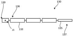
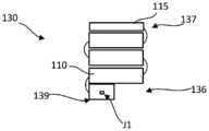
도 1c 및 도 1d에 개략적으로 도시된 바와 같이, 각각의 로봇 아암(130)은 원위 단부 부분(137)과 근위 단부 부분(136)을 포함할 수 있다. 원위 단부 부분(137)(또한 본 명세서에서 "작동 단부"로 지칭됨)은 그것에 결합되는 의료 기구 또는 도구(115)를 포함하거나 구비할 수 있다. 근위 단부 부분(136)(또한 본 명세서에서 "장착 단부 부분" 또는 "장착 단부"로 지칭됨)은 로봇 아암(130)이 테이블(100)에 결합되게 하기 위한 결합 부분을 포함할 수 있다. 로봇 아암(130)은 X, Y 및/또는 Z-축(예를 들어, 도 1a 및 도 1b에 도시됨) 중 하나 이상을 따른 병진 및/또는 이를 중심으로 하는 회전을 제공할 수 있는, 조인트에서 함께 결합되는 둘 이상의 링크 부재 또는 세그먼트(110)를 포함할 수 있다. 로봇 아암(130)의 결합 부분은 결합 메커니즘(139)을 포함할 수 있다. 결합 메커니즘(139)은 아암(130)의 장착 단부(136)에 배치될 수 있고, 세그먼트(110)에 결합될 수 있거나 세그먼트(110) 내에 통합될 수 있다. 로봇 아암(130)은 또한, 결합 메커니즘(139) 및/또는 결합 부분 내에 포함될 수 있거나 결합 부분에 결합되는 로봇 아암(130)의 링크 또는 세그먼트(110) 상에 배치될 수 있는, 로봇 아암(130)의 장착 단부(136)에 또는 그 근처에 배치되는 표적 조인트(J1)를 포함한다. 표적 조인트(J1)는 로봇 아암(130)의 원위 세그먼트가 테이블(100)에 대해 피벗하게 하는 피벗 조인트를 제공할 수 있다. 로봇 아암(130)은, 도 1c에 도시된 바와 같은, 외과 시술 동안에 사용하기 위한 다양한 연장 구성과, 도 1d에 도시된 바와 같은, 사용하지 않을 때 보관을 위한 다양한 절첩 또는 접힘 구성 사이에서 이동될 수 있다.As shown schematically in FIGS. 1C and 1D, each
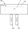
로봇 아암을 수술 테이블에 결합하기 위한 장치 및 방법을 예시하고 설명하는 다양한 실시예가 본 명세서에 개시되어 있다. 전술된 바와 같이 그리고 이하에서 더 상세히 개시되는 다양한 실시예에 따르면, 외과 시술을 수행하는 데 사용하기 위한 로봇 아암이 수술 테이블에 해제가능하게 결합될 수 있다. 일부 실시예에서, 로봇 아암은 테이블 상의 고정된 위치에 결합될 수 있거나, 로봇 아암이 테이블 상판에 대한 다수의 위치로 이동가능할 수 있도록 결합될 수 있다. 예를 들어,도 2a에 개략적으로 도시된 바와 같이, 로봇 아암(230)은 수술 테이블(200)의 테이블 상판(220)에 결합될 수 있다. 수술 테이블(200)은 전술된 수술 테이블(100)과 구조 및 기능이 동일하거나 유사할 수 있다. 예를 들어, 테이블 상판(220)은 외과 시술 중에 환자(P)가 위에 배치될 수 있는 상부 표면을 구비한다. 일부 실시예에서, 로봇 아암(230)은 수술 테이블에 결합되거나 그로부터 분리되는 아암 어댑터에, 고정된 또는 이동가능한 위치에서, 영구적으로 또는 해제가능하게 결합될 수 있다. 예를 들어,도 2b에 개략적으로 도시된 바와 같이, 아암 어댑터(246)가 테이블 상판(220)에 결합될 수 있거나 그로부터 분리될 수 있지만 그와 맞물림가능하거나 그에 결합가능할 수 있다. 로봇 아암(230)은 아암 어댑터(246)에 결합될 수 있다.Various embodiments are disclosed herein illustrating and describing an apparatus and method for coupling a robotic arm to a surgical table. As described above and in accordance with various embodiments disclosed in more detail below, a robot arm for use in performing a surgical procedure may be releasably coupled to a surgical table. In some embodiments, the robot arm can be coupled to a fixed position on the table, or can be coupled such that the robot arm can be moved to multiple positions relative to the table top. For example,as shown schematically in FIG. 2A , the
아암 기부 연결부Arm base connection
도 3에 개략적으로 도시된 바와 같이, 커플러(310)는 로봇 아암(320)을 수술 테이블(300)에 결합시키기 위해 제공될 수 있다. 본 명세서에서 설명되는 바와 같은 커플러(310)는 본 명세서에서 설명되는 수술 테이블들 및 로봇 아암들 중 임의의 것(예컨대, 수술 테이블(100, 200), 로봇 아암(130, 230)), 및 방법들과 함께 사용가능하다. 커플러(310)는 로봇 아암을 위한 단자 기부 부분(A)과 같은 제1 부분(312)(예컨대, 아암 어댑터)을 포함할 수 있다. 커플러(310)는 수술 테이블(300)에 장착하기 위한 기부 부분(B)과 같은 제2 부분(314)을 포함할 수 있다. 제2 부분(314)에 대한 제1 부분(312)의 결합 전에, 로봇 아암(320)은 제1 부분(312)에 결합될 수 있고 테이블 상판(302)은 제2 부분(314)에 결합될 수 있다. 수술 테이블(300)에 대한 로봇 아암(320)의 결합은 테이블(300)에 결합된 로봇 아암이 테이블 상판(302) 상에 배치된 환자 상의 원하는 치료 표적에 도달하게 할 수 있다. 제1 부분(312) 및 제2 부분(314)은 전력 및 데이터 커넥터를 추가로 포함할 수 있다. 제1 부분(312)이 테이블(300)에 결합되고 제2 부분(314)이 로봇 아암(320)에 결합되도록 제1 부분(312)과 제2 부분(314)이 바뀔 수 있다는 것이 이해되어야 한다.As schematically shown in FIG. 3 ,
수술 테이블(300)은 테이블 상판(302), 테이블 지지부(304) 및 테이블 기부(306)를 포함한다. 테이블 상판(302)은 도 1a에 개략적으로 도시된 바와 같이, 외과 시술 동안에 환자가 위에 배치될 수 있는 상부 표면을 구비한다. 테이블 상판(302)은 바닥 위의 적합한 높이에서, 예를 들어 받침대일 수 있는 지지부(304) 상에 배치된다. 지지부(302)는 Z-축(바닥 위로의 높이), (테이블의 종축을 따른) Y-축, 및/또는 (테이블의 횡축을 따른) X-축으로의 병진, 및/또는 Z, Y 및/또는 X-축들을 중심으로 하는 회전과 같은 원하는 수의 자유도로의 테이블 상판(302)의 이동을 제공할 수 있다. 테이블 상판(302)을 위한 지지부(304)는 기부(306)에 장착될 수 있는데, 기부(306)는 수술실의 바닥에 고정될 수 있거나, 예컨대 기부(306) 상의 바퀴들의 사용에 의해 바닥에 대해 이동가능할 수 있다. 로봇 보조식 외과 시술에서, (도 1c 및 도 1d에 개략적으로 도시된) 하나 이상의 로봇 아암(320)이 수술 테이블(300)의 테이블 상판(302) 상에 배치된 환자에 대해 원하는 작동 위치에 배치될 수 있다.The surgical table 300 includes a table
운동학적 장착부 아암 기부 연결부Kinematic Mount Arm Base Connection
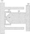
도 4a는 제1 부분(410) 및 제2 부분(420)을 포함하는 커플러(400)의 일 실시예의 측면도이다. 제1 부분(410)과 제2 부분(420)의 결합은 6 자유도가 구속되는 단단한 정합 연결부를 형성한다. 예를 들어, 단단한 정합 연결부는 제2 부분(420)에 대한 제1 부분(410)의 Z-축, Y-축, 및/또는 X-축의 병진, 및/또는 Z, Y, 및/또는 X-축들을 중심으로 하는 회전을 구속한다. 제1 부분(410)은 제1 부분(410)과 제2 부분(420) 사이의 결합을 잠그고 고정하도록 구성된 손잡이(454), 및 대응하는 운동학적 장착부(430)와 접촉하도록 구성된 한 세트의 V-홈(432)들을 포함하는데, 이는 본 명세서에서 설명되는 바와 같다. 제2 부분(420)은 제1 부분(410)과 정합하도록 Y-축을 따라서 병진될 수 있는 포스트(422)(예컨대, 잠금 포스트)를 포함한다. 포스트(422)를 제1 부분(410)에 결합시키는 것은 Y-축을 따르는 병진을 구속할 수 있다.도 4b는 커플러(400)에 대한 X-축, Y-축, 및 Z-축을 도시한다.4A is a side view of one embodiment of a
제2 부분(420)은, 제2 부분(420)의 표면으로부터 돌출되고 대응하는 V-홈(432) 내로 활주하여 그와 정합하도록 구성되는 적어도 3개의 운동학적 장착부를 포함할 수 있는 한 세트의 운동학적 장착부(430)들을 추가로 포함할 수 있다. 운동학적 장착부(430) 및 V-홈(432)은 제1 부분(410)과 제2 부분(420) 사이의 결합의 위치를 찾고, 그 결합을 구속하고, 지지하도록 구성된다. 운동학적 장착부(430)는 구형 또는 반구형 형상을 포함할 수 있다. 운동학적 장착부(430)는 제2 부분(420)의 포스트(422) 둘레에 동일하게 이격될 수 있다. V-홈(432)은 제1 부분(410)에서 V 형상의 절결부를 형성할 수 있고, "V"의 정점에 홈을 추가로 포함할 수 있다. 운동학적 장착부(430)와 V-홈(432) 사이의 홈 내 구체(sphere-in-groove) 정합 연결부는 X-축 및 Z-축으로의 병진을 구속할 수 있고 X-축, Y-축 및 Z-축을 중심으로 하는 회전을 구속할 수 있다.The
제2 부분(420)의 일부 실시예는 제1 부분(410) 내의 대응하는 구멍(도시되지 않음) 내로 접촉 및 활주하여 그와 정합하도록 구성된 하나 이상의 정렬 돌출부(434)를 포함할 수 있다. 정렬 돌출부(434)는 제1 부분(410)과의 돌출부(434)의 정렬이 사용자가 제1 부분(410)을 제2 부분(420) 내로 부정확하게 삽입하는 것을 방지하도록 구성된다는 점에서 비대칭이다. 이러한 공정은 본 명세서에서 정합으로 지칭될 수 있다. 도시된 정렬 돌출부(434)의 형상은 반구형 단부를 갖고 있지만, 특별히 제한되지는 않는다. 제2 부분(420)의 포스트(422)는 정렬 돌출부(434)가 오정렬될 때 제2 부분(420)에 대한 제1 부분(410)의 결합 및 잠금에 참여하기에는 Y-축을 따라서 제1 부분(410) 내로 충분히 병진되지 않을 것이다. 예를 들어,도 4c는 제1 부분(410) 내로 부분적으로 삽입된 제2 부분(420)을 도시한다. 정렬 돌출부(434) 및 정렬 구멍(436)은 제2 부분(420)의 포스트(422)가 제1 부분(410) 내로 완전히 병진되는 것을 허용하도록 배향된다. 그렇지 않으면, 정렬 돌출부(434)는 제1 부분(410)의 하우징과 접촉하여, 제1 부분(410)과 제2 부분(420) 사이에 그들의 결합을 방지하는 갭을 생성한다.Some embodiments of the
도 4d는 제2 부분(420)과 정렬되고 그와 초기 맞물림을 갖는 제1 부분(410)의 사시도를 도시한다. 손잡이(454)(예컨대, 잠금 손잡이)는 커플러(400)의 제1 위치(예컨대, 잠김해제 위치)에 대응하는 제1 위치에 있다. 사용자는 커플러(400)를 제1 구성(예컨대, 잠김해제 상태 또는 위치)으로부터 제2 구성(예컨대, 잠김 상태 또는 위치)으로 전이시키기 위해 손잡이(454)를 제2 위치(예컨대, 잠김 위치)로 회전시킬 수 있다.도 4e는, 포스트(422)가 제1 부분(410) 내로 병진되고 제1 부분(410)과 제2 부분(420)이 정렬되지만 제1 부분(410)과 제2 부분(420) 사이에서 잠금 메커니즘이 맞물리지 않은 제1 구성의 정렬 상태를 도시한다. 특히, 운동학적 장착부(430) 각각은 대응하는 V-홈(432)과 정렬되고 그와 접촉 및 정합하도록 맞물린다.4D shows a perspective view of the
도 4f는 제1 부분(410) 내로의 제2 부분(420)의 초기 병진의 측단면도이다. 이 도면으로부터, 제1 부분(410)이 제1 단부(456)(로봇 아암에 부착되는 단부) 및 제2 단부(458)(제2 부분(420)에 부착되는 단부)를 포함하고, 내부 공동(464)이 제1 단부와 제2 단부 사이에서 제1 부분(410) 내에 형성되어 있는 것을 알 수 있다. 내부 공동에 대한 개구가 제2 단부(458)를 통해 형성된다. 제1 부분(410)은 내부 공동(464) 내에 위치되는 한 세트의 볼 베어링(442)들에 결합된 볼 베어링 홀더(440)(예컨대, 드로우 바(draw bar))를 추가로 포함한다. 한 세트의 볼 베어링(442)들은 볼 베어링 홀더(440)의 원주를 따라서 동일하게 이격된 4개 이상의 볼 베어링을 포함할 수 있다. 손잡이(454)는 제1 면 캠(face cam)(450) 및 제2 면 캠(452)을 포함하는 한 쌍의 캠에 결합될 수 있다. 한 세트의 벨빌 와셔(Belleville washer)(460)들이 볼 베어링 홀더(440)의 샤프트와 결합될 수 있다. 제2 부분(420)의 포스트(422)는 볼 베어링 홀더(440) 내로의 포스트(422)의 병진 및 활주 동안 오정렬을 허용하도록 구성된 제1 표면(423)(예컨대, 도입 테이퍼(lead in taper))을 포함할 수 있다. 포스트는 정합 연결부가 잠길 때 볼 베어링(442)에 대해 가압하도록 구성된 제2 표면(424)(예컨대, 경사진 면)을 추가로 포함할 수 있다. 제1 표면(423) 및 제2 표면(424)은 표면의 곡률에 기초하여 헤르츠 응력(Hertzian stress)을 겪는다. 볼 베어링(442)의 직경 및 재료와 함께, 곡률 및 재료 특성은 표면을 열화시키지 않는 접촉 조건을 생성하도록 구성될 수 있다.4F is a cross-sectional side view of an initial translation of
볼 베어링 홀더(440)는 볼 베어링(442)을 보유하고 포스트(422)를 둘러싸도록 구성된다. 볼 베어링 홀더(440)는 면 캠이 손잡이(454)에 의해 회전될 때 제1 부분(410)의 하우징에 대해 Y-축을 따라서 병진하도록 구성된다. 제1 부분(410) 내로의 볼 베어링 홀더(440)의 병진은 볼 베어링(442)을 제1 부분(410) 내의 표면, 볼 베어링 홀더(440) 내의 표면, 및 포스트(422) 내의 표면 내로 가압한다. 본 명세서에 예시된 바와 같이, 볼 베어링 홀더(440)는 볼 베어링(442)이 포스트(422)와 접촉하지 않을 때 볼 베어링(442)을 홀더(440) 내에 보유하도록 구성된 각각의 볼 베어링 포켓 상에 립(lip)을 포함할 수 있다. 이들 표면은 표면의 곡률에 기초하여 헤르츠 응력을 겪는다. 볼 베어링(442)의 직경 및 재료와 함께, 곡률 및 재료 특성은 표면을 열화시키지 않는 접촉 조건을 생성하도록 구성될 수 있다. 볼 베어링(442)은 볼 베어링 홀더(440) 내에서 미리결정된 범위 내에서 이동하고, 제1 부분(410) 및 제2 부분(420) 둘 모두에 힘을 인가하여 이들을 서로 단단히 잠그고 제1 부분(410)과 제2 부분(420) 사이에 결합을 형성하는 잠금 메커니즘으로서의 역할을 한다.The
도 4g는 잠김 상태(또는 잠김 위치)에 있는 커플러(400)의 단면 사시도로서, 볼 베어링 홀더(440)가 제1 부분(410) 내로 최대로 병진되고 볼 베어링(442)이 포스트(442) 및 하우징(410)과 맞물려서 제1 부분(410)을 제2 부분(420)에 단단히 잠그고 결합시킨 최대로 분리된 위치(예를 들어, 잠김 위치)에 있는 제1 면 캠(450) 및 제2 면 캠(452)을 도시한다. 제1 면 캠(450) 및 제2 면 캠(452)은 Y-축을 따르는 면 캠의 병진이 또한 Y-축을 따라서 볼 베어링 홀더(440)를 병진시키도록 볼 베어링 홀더(440)에 결합된다. 면 캠 각각은 Y-축을 중심으로 하는 (예컨대, 손잡이(454)의 운동으로부터의) 회전 운동을 Y-축을 중심으로 하는 병진 운동으로 변환하는 프로파일을 포함할 수 있다. 손잡이(454)는 면 캠들 중 하나 내로 직접 나사형성될 수 있어서, 그에 의해 면 캠들이 잠김 위치로 회전될 때 토크 이점을 허용할 수 있다. 면 캠들은 제1 및 제2 프로파일들을 갖는 가변 캠 프로파일을 포함할 수 있다. 제1 프로파일은 비교적 더 큰 병진 및 비교적 더 작은 축방향 힘의 이점을 허용하도록 구성될 수 있다. 제2 프로파일은 비교적 더 작은 병진 및 비교적 더 큰 축방향 힘의 이점을 허용하도록 구성될 수 있다. 예를 들어, 제1 프로파일은 가파를 수 있고 제2 프로파일은 얕을 수 있다. 일부 실시예에서, 가변 캠 프로파일은 큰 병진(예컨대, 0.25")에 이어서 매우 작은 병진(예컨대, 0.04")을 허용하도록 구성될 수 있다. 일부 실시예에서, 면 캠은 볼 베어링 홀더가 완전 맞물림에 도달함에 따라 (예컨대, 볼 베어링 홀더가 잠금 위치를 향해 병진함에 따라) 피치를 감소시키는 복합 프로파일을 포함할 수 있다. 일부 실시예에서, 면 캠은 면 캠의 외부 표면 상의 마찰을 감소시키기 위해 스러스트 베어링(thrust bearing)을 포함할 수 있다. 일부 실시예에서, 면 캠은 압력을 균일하게 분포시키도록 구성된 로브(lobe)를 포함할 수 있다. 일부 실시예에서, 면 캠의 상이한 부분은 면 캠의 마찰 및/또는 강도를 가변적으로 변화시키기 위해 상이한 재료로 제조될 수 있다.4G is a cross-sectional perspective view of the
도 4h 내지 도 4l은 다양한 상태에 있는(예컨대, 잠금해제된 및 잠금된) 커플러(400)의 측단면도이다.도 4h는 포스트(422)의 표면이 볼 베어링 홀더(440) 내의 볼 베어링(442)과 접촉하는 초기 맞물림 상태를 도시한다. 손잡이(454)(도시되지 않음) 및 면 캠(450, 452)은 잠김해제 위치에 있다.도 4i는 손잡이(454)(도시되지 않음)의 잠김 위치로의 회전 후의 커플러(400)의 잠김 위치를 도시한다. 손잡이(454)의 회전은 제1 면 캠(450)과 제2 면 캠(452)이 최대로 분리되도록 Y-축을 따르는 면 캠(450, 452)의 병진 운동으로 변환된다. 그에 의해, 면 캠(450, 452)에 결합된 볼 베어링 홀더(440)가 Y-축을 따라서 병진되어 볼 베어링(442) 및 제2 부분(420)을 추가로 제1 부분(410) 내로 가져온다. 볼 베어링(442)과 제1 부분(410) 및 제2 부분(420)의 표면들 사이의 접촉은 제1 부분(410)을 제2 부분(420)에 단단히 맞물고 잠근다.도 4j는 커플러(400)의 잠금 메커니즘의 상세도이다. 잠김 위치에 있는 볼 베어링 홀더(440)는 볼 베어링(442)을 제1 부분(410) 내로 병진시켜서 제1 부분(410)의 접촉 표면(411), 볼 베어링 홀더(440)의 볼 베어링 립(441), 및 포스트(422)의 제2 표면(424)과 접촉을 이룬다. 이러한 접촉력은 손잡이(454)가 잠김해제 위치로 회전될 때까지 Y-축을 따르는 제1 부분(410) 및 제2 부분의 병진을 구속하기에 충분하다. 다시 말하면, 커플러(400)는 결합이 사용자 입력 없이 맞물림해제되지 않을 것이라는 점에서 자가 잠금형(self-locking)이다.4H-4L are side cross-sectional views of
도 4k는 볼 베어링 홀더(440)의 나사형성 샤프트에 결합된 한 세트의 벨빌 와셔(460)들을 도시한다. 벨빌 와셔(460)는 볼 베어링 홀더(440)에 보유력을 인가하도록 구성될 수 있다. 일부 실시예에서, 벨빌 와셔는 약 200 lbf 내지 약 300 lbf를 인가할 수 있다.도 4l은 제1 부분(410)의 하우징의 단부와 벨빌 와셔(460) 사이에 결합된 스프링(462)(예를 들어, 압축 스프링)을 도시한다. 스프링(462)은 볼 베어링 홀더(440)의 위치를 재설정하고 손잡이(454)를 잠김해제 위치로 유지하기 위해 스프링력을 제공하도록 구성될 수 있다. 스프링(462)은 사용자가 손잡이(454)를 잠김해제 위치로 회전시킬 때 볼 베어링 홀더(440)가 도 4f에 도시된 바와 같은 초기 위치를 향해 Y-축을 따라서 병진하도록 볼 베어링 홀더(440)를 잠김해제 위치로 편의시키도록 구성될 수 있다. 벨빌 와셔(460)는 잠금부의 힘을 가변시키도록 구성될 수 있다.4K shows a set of
도 5는, 예컨대 본 명세서에서 설명되는 커플러들 중 임의의 것을 사용함으로써, 로봇 아암을 수술 테이블에 결합시키는 방법(500)의 흐름도이다. 방법(500)은 502에서 커플러의 제2 부분(예컨대, 로봇 아암 기부 부분)을 커플러의 제1 부분(예컨대, 수술 테이블 상판의 장착 부분) 내로 병진시키는 단계를 포함한다(도 4f). 제2 부분의 포스트가 제1 부분 내로 이동함에 따라 포스트는 504에서 정렬하기 시작할 수 있다(도 4c). 제1 부분의 잠금 메커니즘(예컨대, 볼 베어링 홀더, 볼 베어링, 면 캠, 손잡이)은 제2 부분의 정렬 요소(들)가 제1 부분과 정렬되지 않으면 맞물리지 않을 것이다. 포스트가 볼 베어링 홀더와 초기 맞물림 상태에 있을 때(도 4h), 손잡이는 506에서 회전되어 2개의 면 캠들을 회전시킬 수 있다. 일부 실시예에서, 잠금부는 잠김해제 위치로부터 잠김 위치로 약 90도 회전할 수 있다. 잠금부가 그의 원호를 그리며 이동함에 따라, 면 캠은 멀어지게 이동하여 볼 베어링 홀더를 제1 부분 내로 추가로 병진시킨다(도 4i). 볼 베어링 홀더는 볼 베어링들을 제1 부분 및 제2 부분의 표면들에 대해 가압하기 위해 한 세트의 볼 베어링들과 맞물린다(도 4j). 가압력은 508에서 제1 부분과 제2 부분을 서로 잠근다. 볼 베어링 홀더가 잠김 위치로의 손잡이 회전에 응답하여 제1 부분 내로 병진됨에 따라, 한 세트의 운동학적 장착부들이 제1 부분 및 제2 부분을 정밀하게 정렬시키기 위해 대응하는 V-홈과 맞물린다(도 4e). 커플러(400)를 결합해제하기 위해, 사용자는 510에서 손잡이를 잠김해제 위치를 향해 회전시킬 수 있다. 이는 면 캠들을 서로를 향해 회전시키고 볼 베어링 홀더를 제2 부분을 향해 병진시켜서, 그에 의해 볼 베어링과 제1 부분의 하우징 사이의 힘을 해제한다. 잠금부가 맞물림해제되면, 제2 부분은 512에서 제2 부분을 제1 부분의 외부로 병진시킴으로써 제1 부분으로부터 완전히 결합해제될 수 있다.5 is a flowchart of a
도 6a 내지 도 6c는 전력 공급이 중단된 경우 및/또는 응급 작동 시 결합 및 결합해제를 위해 사용될 수 있는 수동 결합 메커니즘을 갖고 모터에 의해 구동되는 커플러(600)의 일 실시예의 사시도이다. 커플러(600)는 제1 부분(610) 및 제2 부분(620)을 포함할 수 있다. 제1 부분(610)과 제2 부분(620)의 결합은 6 자유도가 구속되는 단단한 정합 연결부를 형성한다. 제2 부분(620)은 제1 부분(610)을 둘러싸도록 구성된 포스트(622)를 포함할 수 있다. 포스트(622)는 Y-축을 따라서 병진되어 제1 부분(610)과 정합하여 Y-축을 따르는 병진을 구속할 수 있다.6A-6C are perspective views of one embodiment of a
제1 부분(610)은 한 세트의 볼 베어링(640)들, 부싱(bushing)(632)에 결합된 캠(630), 및 샤프트(634)를 포함할 수 있다. 한 세트의 볼 베어링(640)들은 제1 부분(610)의 원주를 따라서 동일하게 이격된 4개 이상의 볼 베어링을 포함할 수 있다. 한 세트의 볼 베어링(640)들은 제1 부분(610)을 제2 부분(620)에 단단히 맞물고 잠그도록 구성된 잠금 메커니즘에 의해 이동될 수 있다. 캠(630)은 모터 및/또는 손잡이(650)에 의해 구동될 때 제1 부분(610)의 하우징에 대해 Y-축을 따라서 병진하도록 구성된다. 포스트(622) 및 캠(630)은 이들 표면의 곡률에 기초하여 헤르츠 응력을 겪는다. 볼 베어링(640)의 직경 및 재료와 함께, 곡률 및 재료 특성은 그의 표면을 열화시키지 않는 접촉 조건을 생성하도록 구성될 수 있다. 캠(630)의 잠김 위치로의 이동은 한 세트의 볼 베어링(640)들을 제2 부분의 포스트(622)의 표면과 캠(630)의 표면 사이의 접촉력을 유지하는 상태로 위치시킬 것이다. 캠(630) 및 부싱(634)은 샤프트(634)를 따라서 활주가능하도록 구성될 수 있다. 샤프트(634)를 따르는 캠(630)의 이동은 제1 부분(610) 및 제2 부분(620)이 서로에게로 병진될 때 포스트(622)의 접촉 표면에 대한 한 세트의 볼 베어링(640)들의 접촉력을 가변시킬 수 있다. 포스트(622)의 접촉 표면은 볼 베어링(640)을 제2 부분(620) 내에 보유하도록 구성된 포스트 립(624)을 포함할 수 있다. 볼 베어링(640)은 제1 부분(610) 내에서 미리결정된 범위 내에서 이동하고, 제1 부분(610) 및 제2 부분(620) 둘 모두에 힘을 인가하여 이들을 서로 단단히 잠그고 제1 부분(610)과 제2 부분(620) 사이에 결합을 형성하는 잠금 메커니즘으로서의 역할을 한다.The
캠(630)은 제1 부분(610)과 제2 부분(620)을 결합 및 결합해제하기 위해 모터(670)를 사용하여 웜 휠(660) 및 웜(662)을 포함하는 웜 기어에 의해 구동될 수 있다. 모터(670)는, 예를 들어 브러시리스(brushless) DC 모터일 수 있다. 제1 부분(610)은, 샤프트(634)를 따라서 캠(630)을 활주시키고 한 세트의 볼 베어링(640)들을 포스트(622)의 접촉 표면과 맞물리거나 그와의 접촉으로부터 해제하기 위해, 사용자가 작동하게 하도록 구성된 손잡이(650)를 포함할 수 있다. 손잡이(650)는 잠김 위치와 잠김해제 위치 사이에서 회전할 수 있고, 커플러(600)를 잠김 구성과 잠김해제 구성 사이에서 전이시킬 수 있다.도 6a는 커플러(600)의 잠김 위치를 도시한다. 잠김 위치에서, 볼 베어링(640)과 제2 부분(620)의 포스트(622)와 캠(630) 사이의 접촉은 제1 부분(610)을 제2 부분(620)에 단단히 맞물고 잠근다.
잠김해제 위치를 향한 손잡이(650)의 회전은 볼 베어링(640)과 포스트(622)의 표면과 캠(630) 사이의 접촉을 맞물림해제하기 위해 Y-축을 따르는 캠(630)의 병진 운동으로 변환된다. 스프링(664)은 부싱(632)과 웜 휠(660) 사이에서 결합될 수 있고, 캠(630)이 웜 기어를 향해 편의되는 잠김해제 위치로 캠(630)의 위치를 재설정하기 위해 스프링력을 제공하도록 구성될 수 있다.Rotation of the
도 6b에 도시된 바와 같이, 포스트(622)는 제1 부분(610)과 제2 부분(620) 사이에 원하는 수준의 보유력을 제공하도록 구성될 수 있는 하나 이상의 릴리프 절결부(relief cut)(626)를 포함할 수 있다. 예를 들어, 릴리프 절결부(626) 내의 더 넓고/넓거나 더 긴 갭이 제1 부분(610)과 제2 부분(620) 사이의 최대 보유력을 감소시킬 수 있다. 제2 부분(620)은 포스트 립(624)을 추가로 포함할 수 있다. 일부 실시예에서, 커플러(600)는 본 명세서에서 설명되는 바와 같이 운동학적 장착부, V-홈, 및/또는 정렬 요소를 포함할 수 있다.As shown in FIG. 6B , the
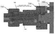
일부 실시예에서, 회전 콜릿은 커플러의 제1 부분과 제2 부분을 결합 및 결합해제하기 위해 사용될 수 있다.도 7a는 커플러(700)의 일 실시예의 단면 사시도이다. 커플러(700)는 외부 하우징(712) 및 제1 부분 나사형성부(714)를 갖는 제1 부분(710)을 포함한다. 커플러(700)는 또한 포스트(722)를 갖는 제2 부분(720)을 포함한다. 그는 Y-축을 따라서 병진되어 제1 부분(710)과 정합하여 Y-축을 따르는 병진을 구속할 수 있다. 제1 부분(710)과 제2 부분(720)의 결합은 6 자유도가 구속되는 단단한 정합 연결부를 형성한다. 제1 부분(710)은 제1 부분(710)과 제2 부분(720) 사이의 결합을 잠그고 고정하도록 구성된 콜릿(750)을 포함할 수 있다. 제1 부분(710)은 포스트(722)를 수용하고, 그와 맞물리고, 그와 함께 잠기도록 구성된 볼 베어링 홀더(740)를 포함한다. 볼 베어링 홀더(740)는 볼 베어링(742)을 보유하고 포스트(722)를 둘러싸도록 구성된다. 볼 베어링 홀더(740)는 콜릿(750)이 회전될 때 제1 부분(710)의 하우징에 대해 Y-축을 따라서 병진하도록 구성된다. 제1 부분(710) 내로의 볼 베어링 홀더(740)의 병진은 볼 베어링(742)을 제1 부분(710), 볼 베어링 홀더(740), 및 포스트(722) 내로 가압한다. 본 명세서에 예시된 바와 같이, 볼 베어링 홀더(740)는 볼 베어링(742)이 포스트(722)와 접촉하지 않을 때 볼 베어링(742)을 홀더(740) 내에 보유하도록 구성된 각각의 볼 베어링 포켓 상에 립을 포함할 수 있다. 이들 표면은 표면의 곡률에 기초하여 헤르츠 응력을 겪는다. 볼 베어링(742)의 직경 및 재료와 함께, 곡률 및 재료 특성은 표면을 열화시키지 않는 접촉 조건을 생성하도록 구성될 수 있다. 볼 베어링(742)은 볼 베어링 홀더(740) 내에서 미리결정된 범위 내에서 이동하고, 제1 부분(710) 및 제2 부분(720) 둘 모두에 힘을 인가하여 이들을 서로 단단히 잠그고 제1 부분(710)과 제2 부분(720) 사이에 결합을 형성하는 잠금 메커니즘으로서의 역할을 한다.In some embodiments, the rotating collet can be used to engage and disengage the first and second portions of the coupler.7A is a cross-sectional perspective view of one embodiment of
한 세트의 벨빌 와셔(760), 잠금 칼라(746), 및 스러스트 베어링(744)이 볼 베어링 홀더(740)에 결합될 수 있다. 콜릿(750)은 포스트(722)를 볼 베어링 홀더(740)에 잠그고 그로부터 잠금해제하기 위해 제1 부분(710)을 중심으로 회전하도록 구성될 수 있다. 콜릿(750)의 외부 표면은 사용자가 제1 부분(710)과 제2 부분(720)을 결합 및 결합해제하기 위해 회전시킬 수 있는 잠금 노브(knob)일 수 있다.A set of
도 7b 내지 도 7d는 상이한 결합 상태에 있는 커플러(700)의 측단면도이다. 도7b에 도시된 결합해제 상태에서, 한 세트의 벨빌 와셔(760)들이 압축되고, (콜릿(750)의) 노브 부분은 안으로 돌려진다. 제2 부분(720)은 제1 부분(710) 내로 병진되고 있지만 볼 베어링 홀더(740)와 접촉을 이루지 않았다. 도7c에서, 제1 부분(710) 및 제2 부분(720)은 포스트(722)가 볼 베어링 홀더(740)와 접촉하는 초기 맞물림을 이루었다. 콜릿(750)은 커플러(700)의 잠김해제 위치에 대응하는 제1 위치에 있다. 한 세트의 벨빌 와셔(760)들은 완전히 압축되고 콜릿(750)의 노브 부분은 안으로 돌려진다. 도7d에서, 콜릿 노브는 볼 베어링 홀더(740)를 제1 부분(710) 내로 당기고 포스트(722)를 제1 부분(710)에 잠그기 위해 밖으로 돌려지도록 회전된다. 한 세트의 벨빌 와셔(760)들은 작업 부하 압축 상태에 있다. 포스트(722) 및 제1 부분(710) 둘 모두는 한 세트의 볼 베어링(742)들을 사용하여 보유력에 의해 보유된다. 한 세트의 볼 베어링(742)들은 볼 베어링 홀더(740)의 원주를 따라서 동일하게 이격된 4개 이상의 볼 베어링을 포함할 수 있다. 일부 실시예에서, 커플러(700)는 본 명세서에서 설명하는 바와 같이 운동학적 장착부, V-홈, 및/또는 정렬 요소를 포함할 수 있다.7B-7D are side cross-sectional views of
리드 스크류 연결부를 갖는 운동학적 장착부Kinematic mount with lead screw connection
도 8은 외부 부하(예컨대, 외과 시술 동안의 로봇 아암의 정적 및 관성 부하)의 존재 시에서도 결합이 6 자유도에서 구속되고 유지되는 것을 보장하기 위해 큰 힘을 발생시킬 수 있는 전동식 잠금 메커니즘에 의해 구동되는 커플러(800)의 일 실시예의 측단면도이다. 커플러(800)는 제1 부분(810) 및 제2 부분(820)을 포함할 수 있다. 제1 부분(810)과 제2 부분(820)의 결합은 6 자유도가 구속되는 단단한 정합 연결부를 형성한다. 이 도면으로부터, 제1 부분(810)이 제1 단부(856)(로봇 아암에 결합되는 단부) 및 제2 단부(858)(제2 부분(820)에 결합되는 단부)를 포함하고, 내부 공동(864)이 제1 단부와 제2 단부 사이에서 제1 부분(810) 내에 형성되어 있는 것을 알 수 있다. 내부 공동(864)에 대한 개구가 제2 단부(858)를 통해 형성된다. 제1 부분(810)은 제1 부분(810)과 제2 부분(820) 사이의 결합을 잠그고 고정하도록 구성된 구동 메커니즘에 결합되는 잠금 메커니즘을 포함할 수 있다. 제2 부분은 Y-축을 따라서 병진되어 제1 부분(810)과 정합하여 Y-축을 따르는 병진을 구속할 수 있는 포스트(822)를 포함한다. 포스트(822)는 회전가능 콜릿(830)의 대응하는 나사형성 부분(832)에 결합될 수 있는 리드 스크류(824)를 포함한다. 리드 스크류(824)를 Y-축을 따라서 제1 부분(810) 내로 병진시키기 위해 모터(850)가 콜릿(830)을 리드 스크류(924)를 중심으로 제1 방향으로 회전시키도록 구동할 수 있다. 이러한 방식으로, 콜릿(830)은 제1 부분(810)을 제2 부분(820)에 단단히 잠그고 결합시키기 위해 포스트(822)와 맞물릴 수 있다. 제1 방향과 반대인 제2 방향으로의 콜릿(830)의 회전은 리드 스크류(824)를 Y-축을 따라 제1 부분(810) 외부로 병진시킬 수 있다. 일부 실시예에서, 리드 스크류(824)의 피치각은 약 2 도 내지 약 30 도일 수 있다. 일부 실시예에서, 리드 스크류(824)의 피치각은 약 10 도 내지 약 15 도일 수 있다. 일부 실시예에서, 리드 스크류(824)의 피치각은 리드 스크류(824)가 역구동되는 것을 방지하도록 구성될 수 있다.8 is driven by an electric locking mechanism that can generate a large force to ensure that the engagement is constrained and maintained in six degrees of freedom even in the presence of external loads (eg, static and inertial loads on the robot arm during surgical procedures). A side cross-sectional view of one embodiment of a
모터(850)는 기어박스(840)에 결합될 수 있고 콜릿(830)을 회전시키도록 구성될 수 있다. 콜릿(830)은 하나 이상의 베어링(834)에 결합될 수 있다. 베어링(834)은, 예를 들어 깊은 홈 볼 베어링일 수 있다. 기어박스(840)는, 예를 들어 유성 또는 하모닉 기어 박스일 수 있고, 약 20 내지 약 200의 기어비를 가질 수 있다. 모터(850)는, 예를 들어 브러시리스 DC 모터일 수 있다. 일부 실시예에서, 전동식 잠금 메커니즘은 적어도 500 N의 힘을 발생시킬 수 있다. 일부 실시예에서, 전동식 잠금 메커니즘은 적어도 1400 N의 힘을 발생시킬 수 있다.
모터(850)는 사용자로부터 입력 커맨드를 수신하도록 구성된 제어기(도시되지 않음)에 결합될 수 있다. 예를 들어, 로봇 아암은, 리드 스크류를 어느 방향으로든 구동함으로써 제1 부분(810)을 제2 부분(820)에 잠그고 그로부터 잠금해제하고, 그에 의해 로봇 아암을 수술 테이블에 부착하고 그로부터 탈거하기 위한 결합 커맨드를 입력할 수 있는 스위치를 포함할 수 있다. 스위치는 수술 테이블, 의료 카트, 및/또는 휴대용 컴퓨팅 디바이스 상에 제공될 수 있다.
일부 실시예에서, 커플러(800)는 제1 부분(810)과 제2 부분(820) 사이의 결합 및 결합해제를 검출하도록 구성된 연결 센서(852)를 포함할 수 있다. 일부 실시예에서, 연결 센서는 제1 부분(810) 및 제2 부분(820) 중 어느 한 부분 상에(예컨대, 제1 부분(810)과 제2 부분(820) 사이의 계면에) 위치된 힘 센서, 홀 효과(Hall effect) 센서, 및 전기 스위치 중 하나 이상을 포함할 수 있다. 일부 실시예에서, 연결 센서는 모터(850) 상에 인코더를 포함할 수 있다. 결합 또는 결합해제가 검출되었을 때까지, 제어기는 모터(850)를 사용하여 콜릿(830)을 구동하도록 구성될 수 있다.In some embodiments,
일부 실시예에서, 커플러(800)는 본 명세서에서 설명되는 바와 같이 운동학적 장착부, V-홈, 및/또는 정렬 요소를 포함할 수 있다. 커플러(800)의 전동식 잠금 메커니즘은 부분 결합 및 결합해제를 포함하는 제2 부분(820)에 대한 제1 부분(810)의 결합 시의 사용자 오류, 유용성 위험(예컨대, 직관적이지 않은 사용)을 감소시킬 수 있고, 안전성(예컨대, 로봇 아암이 바닥으로 또는 사용자의 발 또는 다리 위로 떨어짐)을 증가시킬 수 있다.In some embodiments,
원추형 아암 기부 연결부Conical arm base connection
도 9a는 커플러(900)의 일 실시예의 측면 사시도이다. 커플러(900)는 수술 테이블(예컨대, 수술 테이블(300))에 장착하기 위한 기부 부분과 같은 제1 부분(910)을 포함할 수 있다. 커플러(900)는 로봇 아암을 위한 단자 기부 부분과 같은 제2 부분(920)(예컨대, 아암 어댑터)을 포함할 수 있다. 제1 부분(910)과 제2 부분(920)의 결합은 6 자유도가 구속되는 단단한 정합 연결부를 형성한다. 제1 부분(910)은 제1 부분(910)과 제2 부분(920) 사이의 결합을 잠그고 고정하도록 구성된 손잡이(940), 및 대응하는 정렬 구멍(도시되지 않음)과 접촉하도록 구성된 정렬 돌출부(960)를 포함하는데, 이는 본 명세서에서 설명되는 바와 같다. 제1 부분(910)은 Y-축을 따라서 병진되어 제2 부분(920)의 원추형 수용 구멍(912)(도 9d)과 정합하여 Y-축을 따르는 병진을 구속할 수 있는 원추체(930)를 포함한다.도 9b는 커플러(900)에 대한 X-축, Y-축, 및 Z-축을 도시한다. 제1 부분(910)이 수술 테이블에 결합되고 제2 부분(920)이 로봇 아암에 결합되도록 제1 부분(910)과 제2 부분(920)이 바뀔 수 있다는 것이 이해되어야 한다.9A is a side perspective view of one embodiment of a
제1 부분(910)은 제2 부분(962) 내의 대응하는 정렬 구멍(962) 내로 접촉 및 활주하여 그와 정합하도록 구성된 하나 이상의 정렬 돌출부(960)를 포함할 수 있다. 정렬 돌출부(960)는 제2 부분(920)과의 돌출부(960)의 정렬이 사용자가 제1 부분(910)을 제2 부분(920) 내로 부정확하게 삽입하는 것을 방지하도록 구성된다는 점에서 비대칭이다. 이러한 공정은 본 명세서에서 정합으로 지칭될 수 있다. 정렬 돌출부(960)의 형상이 원통형 형상을 갖는 것으로 도시되어 있지만, 특별히 제한되지는 않는다. 예를 들어, 정렬 돌출부(960)는 스프링 로딩형/스플릿 핀을 포함할 수 있다. 정렬 돌출부(960)가 정렬 구멍(962)과 오정렬될 때, 제1 부분(910)의 원추체(930)는 제2 부분(920)에 대한 제1 부분(910)의 결합 및 잠금에 참여하기에는 Y-축을 따라서 제2 부분(920)의 원추형 구멍(912) 내로 충분히 병진되지 않을 것이다. 예를 들어,도 9d는 원추체(930)가 제2 부분(920) 내로 완전히 병진되는 것을 허용하기 위해 제2 부분(920)의 정렬 구멍(962)과 정렬된 제1 부분(910)의 정렬 돌출부(960)를 도시한다. 그렇지 않으면, 정렬 돌출부(960)는 제2 부분(920)의 하우징과 접촉하여, 제1 부분(910)과 제2 부분(920) 사이에 그들의 결합을 방지하는 갭을 생성한다.The
원추체(930)는 강성을 갖는 기계적 결합을 형성하기 위해 큰 표면적을 제공하도록 구성된다. 예를 들어, 원추체(930)는 X-축 및 Y-축으로의 병진을 구속하고 X-축 및 Z-축을 중심으로 하는 회전을 구속하기 위해 제1 부분(910)과 제2 부분(920)을 결합시키도록 구성된다. 원추체(930)의 표면은 제2 부분(920)과의 적절한 접촉을 보장하는 엄격한 공차 및 표면 마감을 가질 수 있는 정합 표면을 형성한다. 일부 실시예에서, 접촉 표면은 제1 부분(910)과 제2 부분(920) 사이의 마찰을 증가시키도록 구성된 표면 거칠기를 포함할 수 있다. 원추체(930)의 테이퍼 각도는 결합의 높은 강성을 유지하면서 낮은 해제력을 위해 구성될 수 있다. 일부 실시예에서, 원추체(930)는 테이퍼 각도가 약 14 도일 수 있다.The
일부 실시예에서, 원추체(930)는 교번하는 정합 표면과 접촉하는 에지 또는 평면을 포함할 수 있다. 일부 실시예에서, 핀(934)이 원추체(930)의 노우즈(nose)에 배치될 수 있고, 원추체(930)의 표면으로부터 돌출되고 그 표면 내로 리세스되도록 구성될 수 있다. 손잡이(940)가 잠금해제 위치로 회전될 때, 핀은 원추체(930)로부터 돌출되도록 구성되어, 제1 부분(910) 및 제2 부분(920)이 마찰로 인해 접촉 상태로 유지되는 경우에 이들을 서로로부터 멀어지게 밀어냄으로써 제2 부분(920)을 제1 부분(910)으로부터 멀어지게 해제 및 병진시키는 것을 도울 수 있다.In some embodiments,
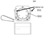
도 9c는 제1 부분(910) 및 제2 부분(920)의 측면도를 도시한다. 원추체(930)는 Y-축을 따르는 제2 부분(920)의 병진을 구속하도록 구성된 둘 이상의 걸쇠(950)를 포함할 수 있다. 예를 들어, 걸쇠(950)들은 원추체(930)의 원추형 테이퍼의 서로 반대편인 횡방향 측부들을 따라서 배치될 수 있다. 걸쇠(950)는 제2 부분(920)에 부착된 로봇 아암이 제1 부분(910)의 원추체(930) 외부로 그리고 그로부터 멀어지게 떨어지는 것을 방지하기 위한 초기 잠금 메커니즘(예컨대, 스프링 걸쇠)으로서 구성될 수 있다. 걸쇠(950)는 원추형 구멍(912)의 표면 위에서 용이하게 활주하도록 구성된 경사진 평탄 표면을 포함할 수 있다. 걸쇠(950)는 제1 부분(910)을 제2 부분(920)에 대해 보유하도록 구성된 테이퍼진 부분을 포함할 수 있다. 제2 부분(920)은, 대응하는 걸쇠(950)를 갖고 걸쇠(950)를 제1 구성으로부터 제2 구성으로 이동시키도록 구성된 스위치(952)를 포함한다. 걸쇠(950)는 제1 구성에서 원추체(930)로부터 돌출되도록 편의될 수 있고 제2 구성에서 원추체(930) 내로 리세스될 수 있다.도 9e는 제2 부분(920)이 원추체(930) 위로 병진되는 것을 도시한다. 제2 부분(920)이 원추체(930) 위로 병진될 때, 걸쇠(950)는 원추형 구멍(912)의 표면과 접촉을 이루고 원추체(930) 내로 리세스된다. 대응하는 축방향 홈(932)(도 9d) 위로 전진된 걸쇠(950)는 걸쇠(950)가 제1 구성에서 돌출되게 하여 그에 의해 초기 잠금 상태에서 제1 부분(910)을 제2 부분(920)에 결합 및 고정시키는데, 이는 도9f에 도시된 바와 같다. 도 9g는 초기 잠금 상태에 있는 제1 부분(910) 및 제2 부분(920)의 사시도이다. 손잡이(940)는도 9d 내지 도 9g에 도시된 단계 전체를 통하여 잠김해제 상태에 있다.9C shows a side view of
도 9h 및도 9m은 걸쇠(950)의 제1 표면(951) 및 제2 표면(953)을 도시한다. 제1 표면(951)은 원추체(930)의 테이퍼 각도의 것과 유사한 각도를 갖는 경사진 평탄 표면일 수 있다. 제1 표면(951)은 걸쇠(950)가 원추형 구멍(912)의 표면 위에서 용이하게 활주하는 것을 허용하도록 구성될 수 있다. 제1 표면(951)이 제2 부분(920)의 원추형 구멍(912)을 통해 병진함에 따라, 걸쇠(950)는 원추체(930) 내로 리세스된다. 제2 표면(953)은 제1 부분(910)을 제2 부분(920)에 대해 보유하도록 구성된 테이퍼진 부분일 수 있다. 걸쇠(950)의 제2 표면(953)은 걸쇠(950)가 돌출 구성에 있을 때 걸쇠(950)가 제2 부분(920)으로부터 결합해제되는 것을 방지하도록 구성된 해제 방지 각도(1044)를 포함할 수 있다. 걸쇠(950)는 돌출 구성을 향해 편의되도록 구성될 수 있다.9H and9M show
일부 실시예에서, 걸쇠(950)는 대응하는 표면과 접촉하도록 구성된 캠작용(camming) 표면을 포함할 수 있어서, 걸쇠를 뒤로 당겨지기보다는 외향으로 웨지결합(wedging)시킴으로써, 제1 부분(910)과 제2 부분(920)이 서로 고정되고 잠길 수 있게 할 수 있다. 예를 들어, 캠작용 표면은 경사진 표면, 볼 및 소켓 표면 등을 포함할 수 있다.In some embodiments,
도 9h는 걸쇠(950) 및 셔틀(970)에 결합된 한 세트의 벨빌 와셔(958)들을 도시한다. 벨빌 와셔(958)는 걸쇠(950)에 보유력을 인가하도록 구성될 수 있다. 일부 실시예에서, 벨빌 와셔(958)는 약 130 lbf 내지 약 230 lbf를 인가할 수 있다. 벨빌 와셔(958)는 잠금부(예를 들어, 손잡이(940), 캠(942), 및 셔틀(970))의 힘을 가변시키도록 구성될 수 있다. 일부 실시예에서, 벨빌 와셔(958)의 예비압축력은 보조 입력을 사용하여 조절될 수 있다.9H shows a set of
캠(942)에 결합된 손잡이(940)가도 9h 및도 9m에 도시되어 있다. 캠(942)은 잠김해제 위치와 잠김 위치 사이에서의 손잡이(940)의 회전에 응답하여 회전하도록 구성된다. 잠김 위치를 향한 캠(942)의 회전은 원추체(930) 내에 배치된 셔틀(970)에 접촉력을 인가한다. 손잡이(940)가 그의 원호를 그리며 회전함에 따라, 캠(942)은 제1 부분(910)의 셔틀(970)에 대해 힘을 인가하여 제1 부분(910)과 제2 부분(920)을 결합하고 제1 부분(910)을 제2 부분(920)에 고강성으로 단단히 잠근다. 손잡이(940)가 잠김 위치에 있을 때, 제1 부분(910)과 제2 부분(920)은 서로 단단히 맞물리고 잠긴다. 일부 실시예에서, 제1 부분은, 손잡이(940) 및 캠(942) 대신, 본 명세서에서 설명되는 바와 같은 전동식 잠금 메커니즘을 포함할 수 있다. 일부 실시예에서, 캠(942)은, 예를 들어 캠(942) 축과 별개인 축을 중심으로 하는 회전 운동 또는 한 세트의 직각 기어들을 통해 간접적으로 회전될 수 있다.A
제2 부분(920)을 (손잡이(940)가 잠김해제 위치에 있는) 초기 잠김 상태로부터 해제하기 위해, 스위치(952)는 눌려짐으로써 작동되어, 그에 의해 걸쇠(950)를 제2 구성으로 누르고 사용자가 제2 부분(920)을 제1 부분(910)으로부터 멀어지게 병진시키게 할 수 있다.도 9i 내지도 9l은 각각 스위치(952)의 정면도, 측면도, 평면도 및 사시도를 도시한다. 스위치(952)는 대응하는 축방향 스위치(950)와 접촉을 이루어 이를 리세스된 제2 구성으로 밀도록 구성된 해제점(956)을 포함할 수 있다. 스위치(952)는 작동될 때 힌지(1054)를 중심으로 회전할 수 있다. 일부 실시예에서, 스위치(952)들은 약 3.5 인치만큼 이격될 수 있다. 이는 사용자가 제2 부분(920) 둘레를 감은 한 손을 사용하여 스위치(952) 둘 모두를 동시에 맞물게 하여, 그에 의해 제2 부분(920)이 제1 부분(910)으로부터 결합해제될 때 아암을 지지하는 (그리고 아암을 떨어뜨릴 가능성을 감소시키는) 위치에 사용자의 손을 배치하는 것을 자연적으로 조장한다. 각각의 스위치(952)는 스위치(952)를 초기 재설정 위치로 편의시키도록 구성된 토션 스프링을 포함할 수 있다.To release the
일부 실시예에서, 제1 부분(910) 및 제2 부분(920)은 각각 제1 부분(910)과 제2 부분(920) 사이에 전력 및/또는 데이터 연결부를 제공하기 위한 전기적 인터페이스(938)를 포함할 수 있다. 전기적 인터페이스는 스프링 접촉 핀, 와이핑 접점, 광섬유 인터페이스, 변압기, 또는 임의의 다른 전력 및/또는 데이터 커넥터 중 하나 이상을 포함할 수 있다. 일부 실시예에서, 제1 부분(910)의 전기적 인터페이스는 원추체(930)의 테이퍼진 표면 상에 또는 원추체(930)를 지지하는 제1 부분(910)의 기부 플랜지 상에 배치될 수 있다. 일부 실시예에서, 걸쇠(950)들 중 하나 이상은 걸쇠(950)가 제2 부분(920)과 접촉하기 때문에 전기적 인터페이스를 포함할 수 있다.In some embodiments,
일부 실시예에서, 커플러(900)는, 본 명세서에서 설명되는 바와 같이, 그리고 제1 부분(910)과 제2 부분(920) 사이의 결합 및 결합해제를 검출하도록 구성된 하나 이상의 연결 센서(936)를 포함할 수 있다. 예를 들어, 연결 센서는 걸쇠(950)가 보유하고 있는 힘의 크기, 걸쇠(950)의 위치(예컨대, 걸쇠가 이동한 양), 및 원추체(930)와 제2 부분(920) 사이의 접촉 상태 중 하나 이상을 검출하도록 구성될 수 있다.In some embodiments,
일부 실시예에서, 제1 부분(910) 및 제2 부분(920) 중 하나 이상은 제1 부분(910)을 제2 부분(920)으로부터 진동 분리시키도록 구성된 댐퍼를 포함할 수 있다.In some embodiments, one or more of the
도 10은, 예컨대 본 명세서에서 설명되는 커플러들 중 임의의 것을 사용함으로써, 로봇 아암을 수술 테이블에 결합시키는 방법(1000)의 흐름도이다. 방법(1000)은 1002에서 커플러의 제2 부분(예컨대, 로봇 아암 기부 부분)을 커플러의 제1 부분(예컨대, 수술 테이블 상판의 장착 부분) 위에서 병진시키는 단계를 포함한다(도 9e). 제1 부분의 원추형 테이퍼가 초기 정렬을 제공할 수 있다. 1004에서, 제2 부분은, 제1 부분 및 제2 부분의 각각 상의 대응하는 정렬 요소들을 정렬시킴으로써 제2 부분이 제1 부분의 원추체 위에서 병진됨에 따라 제1 부분과 추가로 정렬된다. 제1 부분의 잠금 메커니즘(예컨대, 걸쇠)은 제1 부분의 정렬 요소(들)가 제2 부분과 정렬되지 않으면 제2 부분과 맞물리지 않을 것이다. 걸쇠는 1006에서 제2 부분과 맞물린다(도 9f). 제2 부분에 대한 걸쇠의 이러한 초기 결합은, 사용자 입력(예컨대, 스위치의 사용자 작동) 없이 결합이 맞물림해제되지 않을(예컨대, 해제되지 않을) 것이라는 점에서 자가 잠금형이다. 이 때, 제1 부분과 제2 부분은, 제2 부분이 사용자에 의해 지지되지 않은 경우 제2 부분이 제1 부분으로부터 멀리 떨어질 수 없도록 초기 맞물림 상태에서 결합된다.10 is a flowchart of a
초기 맞물림 상태에 있는 동안, 1008에서 손잡이가 회전되어 제1 부분의 2-위치 캠을 회전시켜 원추체 내에 배치된 셔틀에 접촉력을 인가할 수 있다. 손잡이가 그의 원호를 그리며 회전함에 따라, 캠은 제1 부분의 셔틀에 대해 힘을 인가하여 제1 부분과 제2 부분을 결합하고 제1 부분을 제2 부분에 고강성으로 단단히 잠근다. 일부 실시예에서, 손잡이는 잠김해제 위치로부터 잠김 위치로 약 90도 회전할 수 있다. 제1 부분과 제2 부분은 1010에서 잠긴다.While in the initial engagement, the handle can be rotated at 1008 to apply a contact force to the shuttle disposed within the cone by rotating the two-position cam of the first portion. As the handle rotates in its arc, the cam applies a force against the shuttle of the first portion to engage the first portion and the second portion and tightly lock the first portion to the second portion. In some embodiments, the handle can rotate about 90 degrees from the unlocked position to the locked position. The first and second parts are locked at 1010.
제1 부분을 제2 부분으로부터 맞물림해제하기 위해, 손잡이는 걸쇠 스위치가 작동되기 전에 잠김해제 위치로 회전되어야 한다. 우발적인 결합해제는 사용자에 의해 결합해제되는 필수적인 두 개의 잠금부에 의해 감소된다. 손잡이는 1012에서 잠김해제 위치를 향해 회전되어, 캠을 회전시키고 그를 셔틀로부터 결합해제시킬 수 있다. 잠김해제 위치로의 손잡이의 회전은 제1 부분과 제2 부분을 완전히 결합해제시키지 않고, 사용자가 제2 부분에 결합된 로봇 아암의 질량을 지지하는 것을 허용한다. 하나 이상의 스위치의 작동은 1014에서 걸쇠를 원추체 내로 리세스시키고, 1016에서 제2 부분이 제1 부분의 원추체 외부로 그리고 그로부터 멀어지게 병진하게 한다.To disengage the first portion from the second portion, the handle must be rotated to the unlocked position before the latch switch is actuated. Accidental disengagement is reduced by two essential locks that are disengaged by the user. The handle can be rotated toward the unlocked position at 1012 to rotate the cam and disengage it from the shuttle. Rotation of the handle to the unlocked position allows the user to support the mass of the robot arm coupled to the second portion without completely disengaging the first portion and the second portion. Operation of the one or more switches recesses the latch into the cone at 1014 and causes the second portion to translate out of and away from the cone of the first portion at 1016.
반경방향 클램핑 아암 기반 연결부Radial clamping arm based connection
도 11a,도 11e 및 도11h는 제1 부분(1110) 및 제2 부분(1120)을 포함하는 커플러(1100)의 실시예의 측단면도이다. 제1 부분(1110)과 제2 부분(1120)의 결합은 6 자유도가 구속되는 단단한 정합 연결부를 형성한다. 제1 부분 및 제2 부분은 각각 커플러(1100)를 통하여 전력 및 데이터를 제공하기 위한 전기적 인터페이스(1126)를 포함할 수 있다. 제1 부분(1110)은 제1 부분(1110)을 제2 부분(1120)에 결합시키도록 구성된 스프링(1114)에 결합된 볼 베어링(1112)을 포함한다. 일부 실시예에서, 포지티브 잠금부(positive lock)가 스프링 백(spring back)을 방지하기 위해 스프링(1114)에 추가로 결합될 수 있다. 제2 부분(1120)은 제1 부분(1110)과 정합하도록 Y-축을 따라서 병진될 수 있는 포스트(1122)를 포함한다. 제2 부분(1120)은 제1 표면(1123) 및 제2 표면(1124)을 포함할 수 있다. 제2 표면(1124)은 제1 표면(1123)에 대해 더 가파른 각도를 가질 수 있다. 반경방향 클램프(1130)가 제2 부분(1120) 둘레에 배치될 수 있다. 제1 부분(1110)에 대한 포스트(1122)의 결합은 Y-축을 따르는 병진을 구속할 수 있다.11A ,11E and11H are side cross-sectional views of an embodiment of a
도 11a는 제2 부분(1120)과 정렬되고 그와 초기 맞물림을 갖는 제1 부분(1110)을 도시한다. 제2 부분(1120)의 포스트(1122)는 제1 부분(1110) 내로의 포스트(1122)의 병진 및 활주 동안 오정렬을 허용하도록 구성된 제1 표면(1123)(예컨대, 도입 테이퍼)을 포함할 수 있다. 포스트(1122)는 볼 베어링(1124)에 대해 가압하도록 구성된 제2 표면(1124)(예컨대, 경사진 면)을 추가로 포함할 수 있다. 제1 표면(1123) 및 제2 표면(1124)은 표면의 곡률에 기초하여 헤르츠 응력을 겪는다. 볼 베어링(1124)의 직경 및 재료와 함께, 곡률 및 재료 특성은 표면을 열화시키지 않는 접촉 조건을 생성하도록 구성될 수 있다.11A shows
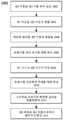
클램프(1130)는 제1 부분(1110)을 제2 부분(1120)에 잠그도록 조여질 수 있다.도 11b 내지 도 11d는 액추에이터(1140)에 결합된 반경방향 클램프(1130)의 전방 단면도이다. 액추에이터(1140)는 나사(1142) 및 손잡이(1144)를 포함할 수 있다. 손잡이(1144)를 작동시키는 사용자는 스크류(1142)를 돌려서 제2 부분(1120) 상의 클램프(1130)의 반경방향 압축력을 가변시킬 수 있다. 액추에이터(1140)는 피벗 또는 회전될 수 있다. 일부 실시예에서, 액추에이터(1140)는 1/4 바퀴로 회전되어 클램프(1130)의 원하는 반경방향 압축을 달성할 수 있다. 클램프(1130)는 또한 압축력을 분산시키기 위해 하나 이상의 릴리프(1132)를 포함할 수 있다. 클램프는 미리결정된 범위 내에서 압축되고, 제1 부분(1110) 및 제2 부분(1120) 둘 모두에 힘을 인가하여 이들을 서로 단단히 잠그고 제1 부분(1110)과 제2 부분(1120) 사이에 결합을 형성하는 잠금 메커니즘으로서의 역할을 한다.The
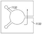
도 11e는 제1 콜릿(1150) 및 제2 콜릿(1152)을 포함하는 커플러(1100)를 도시한다. 제1 콜릿(1150)은 제1 부분(1110)과 제2 부분(1120) 사이에서 제2 부분(1120)의 단부에 결합되도록 구성될 수 있다. 제2 콜릿(1152)은 제1 부분(1110)과 제2 부분(1120) 사이에서 제2 부분(1120)의 기부 부분에 결합되도록 구성될 수 있다. 제1 콜릿(1150) 및 제2 콜릿(1152) 둘 모두는 사용자가 Y-축을 따라서 병진시키기 위한 손잡이(1162)를 갖는 토글부(toggle)(1160)에 결합된다. 콜릿의 외부 표면 및 내부 표면은, 콜릿이 제1 부분과 제2 부분 사이에서 병진 및 압축될 수 있도록 각각의 제1 부분 및 제2 부분의 각도와 매칭될 수 있다. 일부 실시예에서, 콜릿은 미리결정된 압축력을 제공하기 위해 한 세트의 벨빌 와셔들에 결합될 수 있다. 제1 콜릿(1150) 및 제2 콜릿(1152)은 각각 제1 부분(1110)을 향한 토글부(1160)의 병진이 콜릿을 압축하고 제1 부분과 제2 부분 사이의 결합을 고정시키도록 하나 이상의 슬릿(1151, 1153)(도 11f 및 도 11g 참조)을 포함할 수 있다. 콜릿은 미리결정된 범위 내에서 병진 및 압축되고, 제1 부분(1110) 및 제2 부분(1120) 둘 모두에 힘을 인가하여 이들을 서로 단단히 잠그고 제1 부분(1110)과 제2 부분(1120) 사이에 결합을 형성하는 잠금 메커니즘으로서의 역할을 한다. 일부 실시예에서, 미리결정된 힘으로의 콜릿의 압축은 전기적 인터페이스 연결부를 형성한다.11E shows a
도 11h는 제1 클램프(1134) 및 제2 클램프(1136)를 포함하는 커플러(1100)를 도시한다. 제1 클램프(1134)는 제2 부분(1120)의 단부에 결합되어 그에 대한 반경방향 압축력을 가변시키도록 구성될 수 있다. 제2 클램프(1136)는 결합되어 반경방향 압축력을 가변시키도록 구성될 수 있다. 일부 실시예에서, 제1 클램프(1134) 및 제2 클램프(1136)는,도 11i에 도시된 바와 같이, 각각의 제1 캠(1170) 및 제2 캠(1172)에 결합될 수 있다. 캠들 각각은 손잡이에 결합될 수 있고, 제2 부분(1120) 상에서 반경방향 압축력을 가변시키도록 함께 작동될 수 있다. 제1 캠(1170) 및 제2 캠(1172)은 상이한 프로파일을 가질 수 있고, 회전 또는 선형 운동을 사용하여 작동될 수 있다. 더욱이, 캠(1170, 1172)은 클램프(1134, 1136)의 상이한 타이밍, 상이한 압축 및/또는 선형 운동 및 클램핑을 허용할 수 있다. 클램프 각각은 미리결정된 범위 내에서 압축되고, 제1 부분(1110) 및 제2 부분(1120) 둘 모두에 힘을 인가하여 이들을 서로 단단히 잠그고 제1 부분(1110)과 제2 부분(1120) 사이에 결합을 형성하는 잠금 메커니즘으로서의 역할을 한다. 일부 실시예에서, 미리결정된 힘으로의 반경방향 클램프의 압축은 전기적 인터페이스 연결부를 형성한다.FIG. 11H shows a
도 12는, 예컨대 본 명세서에서 설명되는 커플러들 중 임의의 것을 사용함으로써, 로봇 아암을 수술 테이블에 결합시키는 방법(1200)의 흐름도이다. 방법(1200)은 1202에서 커플러의 제2 부분(예컨대, 로봇 아암 기부 부분)을 커플러의 제1 부분(예컨대, 수술 테이블 상판의 장착 부분) 내로 병진시키는 단계를 포함한다. 제2 부분의 포스트가 제1 부분 내로 이동함에 따라 포스트는 1204에서 정렬하기 시작할 수 있다. 제1 부분의 잠금 메커니즘(예컨대, 반경방향 클램프, 손잡이, 액추에이터, 노브)은 제2 부분의 정렬 요소(들)가 제1 부분과 정렬되지 않으면 맞물리지 않을 것이다. 포스트가 한 세트의 볼 베어링들에 대해 초기 맞물림 상태에 있을 때, 손잡이는 1206에서 회전되어 반경방향 클램프를 압축할 수 있다. 반경방향 클램프의 가압력은 1208에서 제1 부분과 제2 부분을 서로 잠근다. 커플러(1200)를 결합해제하기 위해, 사용자는 1210에서 손잡이를 잠김해제 위치를 향해 회전시킬 수 있다. 이는 반경방향 클램프를 압축해제시켜서, 그에 의해 볼 베어링과 제2 부분의 하우징 사이의 힘을 해제한다. 잠금부가 맞물림해제되면, 제2 부분은 1212에서 제2 부분을 제1 부분의 외부로 병진시킴으로써 제1 부분으로부터 완전히 결합해제될 수 있다.12 is a flowchart of a
다른 아암 기부 연결부Other arm base connection
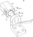
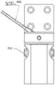
도 13a 내지 도 13d는 제1 부분(1310) 및 제2 부분(1320)을 포함하는 커플러(1300)의 실시예의 사시도이다. 제1 부분(1310)과 제2 부분(1320)의 결합은 6 자유도가 구속되는 단단한 정합 연결부를 형성한다. 제1 부분 및 제2 부분은 각각 커플러(1300)를 통하여 전력 및 데이터를 제공하기 위한 전기적 인터페이스를 포함할 수 있다. 포스트 구멍(1312)은도 13a 내지 도 13c에 도시된 제2 전기 커넥터(1330)에 결합되도록 구성된도 13c에 도시된 제1 전기 커넥터(1316)를 포함할 수 있다.13A-13D are perspective views of an embodiment of a
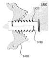
제2 부분(1320)은 제1 부분(1310)과 정합하도록 Y-축을 따라서 병진될 수 있는 포스트(1322)를 포함한다. 포스트(1322)는 제1 구성에서 포스트(1322)로부터 돌출되도록 그리고 제2 구성에서 포스트(1322) 내로 리세스되도록 편의된 한 세트의 걸쇠(1324)들을 포함할 수 있다. 제1 부분(1320)은 포스트 구멍(1312), 및 제2 부분(1320)의 한 세트의 걸쇠(1324)들에 대응하는 한 세트의 걸쇠 구멍(1314)들을 포함한다. 걸쇠(1324)는 모터(1340)에 결합된 리드 스크류(1342)에 의해 구동될 수 있다. 리드 스크류(1342)가 Y-축을 따라서 병진됨에 따라, 리드 스크류(1342)에 결합된 선형 랙(1350)이 Y-축을 따라서 병진하고 제1 구성과 제2 구성 사이에서 걸쇠(1360)를 회전시킨다. 이러한 전동식 잠금 메커니즘은 제1 부분(1310)과 제2 부분(1320) 사이의 단단한 결합을 보장할 수 있다. 제2 부분(1320)은 사용자가 공구(예컨대, 앨런 렌치(Allen wrench))를 수동으로 삽입하여 선형 랙(1350)을 수동으로 역구동시키고 수술 테이블로부터의 로봇 아암의 결합해제를 가능하게 하기 위한 접근 포트(1370)(도13d 참조)를 포함할 수 있다. 모터(1340)는, 예를 들어 브러시리스 DC 모터일 수 있다.The
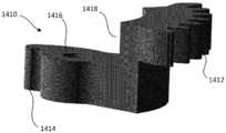
도 14a 내지 도 14e는 선형 랙(1420) 및 걸쇠(1410)를 포함하는 선형 랙 조립체(1400)의 외부 도면이다. 선형 랙(1420)은 일 면의 랙(1422)(도14c 참조)이 다른 면의 것과 상호교환가능하다는 점에서 양면형일 수 있다. 다시 말하면,도 14c의 랙(1422)은 대칭이도록 뒤집히고 정합될 수 있다. 선형 랙(1420)은 걸쇠(1410)(예컨대, 회전 캠 클로)에 대한 컴플라이언스(compliance)를 증가시키기 위해 하나 이상의 벨빌 와셔를 포함할 수 있다. 각각의 랙이 함께 가압하게 하도록 각각의 랙의 일 단부에 포스트가 제공될 수 있다. 와셔(1430)가 랙(1422)의 정합 표면들 사이에 배치되어 컴플라이언스 및 스프링 저항을 부가할 수 있다. 걸쇠(1410)는도 14d 및 도 14e에 의해 예시된 바와 같은 오프셋(1418)에 의해 높이가 분리된 스퍼 기어(1412) 및 캠 클로(1414)를 포함할 수 있다. 걸쇠(1410)는 축(1416)을 중심으로 회전할 수 있다. 캠 클로(1414)는 걸쇠가 회전함에 따라 제1 부분의 대응하는 표면과 정합할 수 있다.14A-14E are exterior views of
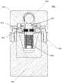
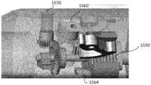
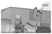
도 15a 내지 도 15c는 일 실시예에 따른 커플러(1500)의 내부 사시도이다. 일부 실시예에서, 커플러(1500)는 제1 구성에서 하우징의 표면으로부터 돌출되도록 그리고 제2 구성에서 하우징 내로 리세스되도록 편의된 한 세트의 3개의 걸쇠를 포함할 수 있다. 걸쇠(1560, 1562, 1564)는 모터(1540)에 결합된 리드 스크류(1542)에 의해 구동될 수 있다. 리드 스크류(1542)가 Y-축을 따라서 병진됨에 따라, 리드 스크류(1542)에 결합된 선형 랙(1550)이 Y-축을 따라서 병진하고 제1 구성과 제2 구성 사이에서 걸쇠(1560, 1562, 1564)를 회전시킨다. 커플러(1500)는 사용자가 공구(예컨대, 앨런 렌치)를 수동으로 삽입하여 선형 랙(1550)을 수동으로 역구동시키고 수술 테이블로부터의 로봇 아암의 결합해제를 가능하게 하기 위한 접근 포트(1570)를 포함할 수 있다. 모터(1540)는, 예를 들어 브러시리스 DC 모터일 수 있다.15A-15C are internal perspective views of
도 16a 및 도 16b는 전동식 잠금 메커니즘을 포함하는 커플러(1600)의 내부 및 외부 도면이다. 제1 부분(1610)은 제2 부분(1620)의 해제 부재(1630)에 대해 보유력을 인가하도록 구성된, 볼 베어링(1650)에 결합된 모터(1640)를 포함할 수 있다. 모터(1640)는 미리결정된 범위 내에서 하향력을 인가하고, 제1 부분(1610) 및 제2 부분(1620) 둘 모두에 힘을 인가하여 이들을 서로 단단히 잠그고 제1 부분(1610)과 제2 부분(1620) 사이에 결합을 형성하는 진동 댐퍼 및 잠금 메커니즘으로서의 역할을 한다. 해제 부재(1630)는 볼 베어링(1650)과 접촉하도록 구성된 베어링 표면(1634)을 포함한다. 베어링 표면(1634)은 베어링(1650)이 해제 부재(1630) 내로 리세스되게 하도록 테이퍼진 또는 램프형 표면을 포함한다. 해제 부재(1630)는 힌지(1632)를 중심으로 회전할 수 있다. 핀(1642)이 해제 부재(1630)를 고정시킬 수 있다. 그러나, 핀(1642)이 해제될 때, 베어링(1650)의 중력의 힘 및 하향 압력은 제1 부분(1610)과 제2 부분(1620) 사이의 접촉력을 해제하기 위해 해제 부재(1630)가 스윙 개방되게 하여, 그에 의해 제1 부분(1610)과 제2 부분(1620)을 결합해제할 것이다.16A and 16B are internal and external views of
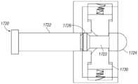
도 17a 내지 도 17d는 병진 메커니즘을 포함하는 커플러(1700)의 개략 측면도이다. 제1 부분(1710)은 제2 부분(1720)의 포스트(1722)를 고정시키기 위해 한 세트의 래치(1730)들을 포함하는 캐리지(carriage)를 포함할 수 있다. 제1 부분(1710)과 제2 부분(1720)을 결합시키기 위해, 포스트(1722)는 제1 부분(1710) 내로 병진된다. 제1 부분(1710)과 제2 부분(1720)을 결합해제하기 위해, 포스트는 제1 부분(1710) 내로 미리결정된 거리에 걸쳐 추가로 병진되고, 이어서 제1 부분(1710)과 제2 부분(1720)을 결합해제시키도록 후퇴될 수 있다.17A-17D are schematic side views of
도 17a 및 도 17b에서, 원위 헤드(1724)가 제1 부분(1710) 내로 병진되어 래치(1730)의 경사진 제1 표면(1732)과 접촉한다. 래치는 다른 래치를 향해 연장되도록 편의된 스프링(1740)에 결합될 수 있다. 원위 헤드(1724)는 래치(1730)가 포스트(1722)의 제2 직경 부분(1723)과 접촉하도록 래치를 통해 활주한다. 이 때, 포스트(1722)는 래치(1730)와 원위 헤드(1724)의 근위 단부 사이의 접촉에 의해 제1 부분(1710)으로부터 후퇴되는 것이 방지된다. 포스트(1722)는 포스트(1722)의 제2 직경 부분(1723)을 따라서 활주할 수 있는 슬라이딩 칼라(1726)를 포함한다.In FIGS. 17A and 17B ,
도 17c 및 도 17d에서, 포스트(1722)는 래치(1730)가 제2 직경 부분(1723)을 따라서 활주하도록 제1 부분(1710) 내로 추가로 병진된다. 래치(1730)의 제1 표면(1732)은 래치(1730)가 슬라이딩 칼라(1726)를 제자리에 보유하도록 슬라이딩 칼라(1726)의 제1 표면(1927)에 대항하여 활주하도록 구성된다. 이 때, 제1 부분(1710)으로부터 멀어지는 포스트(1722)의 후퇴는, 슬라이딩 칼라가 래치(1730)에 대해 고정된 상태로 유지되는 동안, 원위 헤드(1724)를 역방향으로 병진시킬 것이다. 다시 말하면, 슬라이딩 칼라(1726)는 근위 단부로부터 원위 단부까지 제2 직경 부분(1723)을 따라서 활주할 것이다. 슬라이딩 칼라(1726)가 원위 헤드(1724)와 접촉할 때, 래치(1730)의 개구는 원위 헤드(1724)가 제1 부분(1710)으로부터 멀어지게 후퇴하는 것이 방지되지 않도록 하는 직경을 갖는다. 일부 실시예에서, 근위 단부에 있는 원위 헤드(1724)는 슬라이딩 칼라(1726)를 보유하기 위한 리세스를 포함할 수 있다.17C and 17D ,
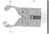
도 18a 및 도 18b는 이전 실시예들 중 임의의 실시예의 커플러의 포스트를 둘러싸고 파지하도록 구성된 파지기(1800)의 측면도이다. 파지기(1800)는 커플러(예컨대, 커플러(400))의 포스트(예컨대, 포스트(422))의 종축에 횡방향 힘을 인가하도록 작동가능한 아암(1802, 1804)을 포함한다.18A and 18B are side views of a
다양한 실시예가 전술되었지만, 그들은 제한이 아닌 단지 예로서 제시되었음을 이해하여야 한다. 전술된 방법이 소정 순서로 발생하는 소정 이벤트를 나타내는 경우, 소정 이벤트의 순서화는 수정될 수 있다. 또한, 이벤트 중 소정의 것은 가능한 경우 병렬 과정으로 동시에 수행될 수 있을 뿐만 아니라, 전술된 바와 같이 순차적으로 수행될 수 있다.While various embodiments have been described above, it should be understood that they have been presented by way of example only, and not limitation. If the above-described method indicates a predetermined event occurring in a predetermined order, the ordering of the predetermined event may be modified. In addition, certain of the events may be performed simultaneously in a parallel process if possible, as well as performed sequentially as described above.
전술된 개략도 및/또는 실시예가 소정 배향 또는 위치로 배열된 소정 구성요소를 나타내는 경우, 구성요소의 배열은 수정될 수 있다. 실시예가 특히 도시되고 기술되었지만, 형태 및 상세 사항에 있어서 다양한 변경이 이루어질 수 있음이 이해될 것이다. 본 명세서에서 설명되는 장치 및/또는 방법의 임의의 부분은 상호 배타적인 조합을 제외하고는 임의의 조합으로 조합될 수 있다. 본 명세서에서 설명되는 실시예는 기술된 상이한 실시예의 기능, 구성요소 및/또는 특징부의 다양한 조합 및/또는 하위조합을 포함할 수 있다.When the above schematic and / or embodiments represent certain components arranged in a certain orientation or position, the arrangement of the components may be modified. While the embodiments have been particularly shown and described, it will be understood that various changes in form and detail may be made. Any portion of the devices and / or methods described herein may be combined in any combination except for mutually exclusive combinations. Embodiments described herein may include various combinations and / or subcombinations of the functions, components, and / or features of the different embodiments described.
본 발명의 앞서 기록된 설명은 당업자가 현재 그의 최상의 모드인 것으로 간주되는 것을 제조 및 사용하는 것을 가능하게 하지만, 당업자는 본 명세서의 특정 실시예, 방법 및 예의 변형, 조합 및 등가물의 존재를 이해하고 인식할 것이다. 본 명세서에 제시된 몇몇 아이디어들에 대해, 하나 이상의 부분은 선택적일 수 있다. 따라서, 본 발명은 전술된 실시예, 방법 및 예에 의해 제한되는 것이 아니라, 본 발명의 범주 및 사상 내의 모든 실시예 및 방법에 의해 제한된다.While the foregoing written description of the invention enables those skilled in the art to make and use what are presently considered to be their best mode, those skilled in the art will understand the existence of variations, combinations, and equivalents of certain embodiments, methods, and examples herein. Will recognize. For some of the ideas presented herein, one or more portions may be optional. Thus, the present invention is not limited by the above-described embodiments, methods, and examples, but is limited by all embodiments and methods within the scope and spirit of the present invention.
Claims (20)
Translated fromKorean수술 테이블에 결합되도록 구성된 제1 부분;
로봇 아암에 결합되도록 구성된 제2 부분 - 상기 제2 부분은 상기 제1 부분의 제1 축을 따라서 병진하여 상기 제2 부분을 상기 제1 부분에 결합시키도록 구성된 포스트(post)를 가짐 -; 및
잠김 위치와 잠김해제 위치 사이에서 상기 제1 부분과 상기 제2 부분 사이의 결합을 전이시키도록 구성된 잠금 메커니즘 - 상기 잠김 위치에서, 상기 제2 부분에 대한 상기 제1 부분의 6 자유도로의 이동이 구속됨 - 을 포함하는, 커플러.A coupler for coupling a robotic arm to a surgical table,
A first portion configured to be coupled to a surgical table;
A second portion configured to be coupled to a robotic arm, the second portion having a post configured to translate along the first axis of the first portion to couple the second portion to the first portion; And
A locking mechanism configured to transfer an engagement between the first portion and the second portion between the locked position and the unlocked position—in the locked position, movement of the first portion relative to the second portion in six degrees of freedom Constrained-including.
상기 원추체의 측부를 따라 배치되는 걸쇠(catch) - 상기 걸쇠는 제1 구성에서 상기 원추체의 측부로부터 돌출되도록 편의되고, 제2 구성에서 상기 원추체의 측부 내로 후퇴됨 -; 및
상기 제2 부분을 상기 제1 부분에 결합시키기 위해 상기 제1 구성에서 상기 제1 부분의 걸쇠를 수용하기 위한, 상기 제2 부분의 원추형 수용 공동의 내부 표면을 따라 형성된 걸쇠 홈, 또는 상기 걸쇠를 상기 제1 구성과 상기 제2 구성 사이에서 전이시키기 위한 스위치를 추가로 포함하는, 커플러.The method of claim 10,
A catch disposed along the side of the cone, the catch being biased to protrude from the side of the cone in a first configuration, and retracted into the side of the cone in a second configuration; And
A clasp groove formed along the inner surface of the conical receiving cavity of the second portion, or the clasp, for receiving the clasp of the first portion in the first configuration to couple the second portion to the first portion. And a switch for transitioning between the first configuration and the second configuration.
수술 테이블에 결합되도록 구성된 제1 단부 및 제2 단부를 갖는 제1 부분 - 상기 제2 단부는 상기 제1 부분 내의 내부 공동에 대한 개구를 한정함 -;
로봇 아암에 결합되도록 구성된 제2 부분 - 상기 제2 부분은 상기 내부 공동 내에 수용되도록 그리고 상기 제1 부분의 제1 축을 따라서 병진하여 상기 제2 부분을 상기 제1 부분에 결합시키도록 구성된 포스트를 가짐 -;
상기 제2 부분에 대한 상기 제1 부분의 6 자유도로의 이동을 구속하도록 구성된 잠금 메커니즘; 및
상기 잠금 메커니즘의 작동을 구동하도록 구성된 구동 메커니즘을 포함하는, 커플러.As a coupler for coupling the robot arm to the surgical table,
A first portion having a first end and a second end configured to be coupled to a surgical table, the second end defining an opening for an internal cavity in the first portion;
A second portion configured to engage the robot arm, the second portion having a post received within the inner cavity and configured to translate along the first axis of the first portion to couple the second portion to the first portion -;
A locking mechanism configured to constrain the movement of the first portion to six degrees of freedom relative to the second portion; And
And a drive mechanism configured to drive actuation of the locking mechanism.
Applications Claiming Priority (5)
| Application Number | Priority Date | Filing Date | Title |
|---|---|---|---|
| US201762476816P | 2017-03-26 | 2017-03-26 | |
| US62/476,816 | 2017-03-26 | ||
| US15/934,709US11078945B2 (en) | 2017-03-26 | 2018-03-23 | Coupler to attach robotic arm to surgical table |
| US15/934,709 | 2018-03-23 | ||
| PCT/US2018/024393WO2018183212A1 (en) | 2017-03-26 | 2018-03-26 | Coupler to attach robotic arm to surgical table |
Publications (2)
| Publication Number | Publication Date |
|---|---|
| KR20190112829Atrue KR20190112829A (en) | 2019-10-07 |
| KR102326102B1 KR102326102B1 (en) | 2021-11-17 |
Family
ID=63581657
Family Applications (1)
| Application Number | Title | Priority Date | Filing Date |
|---|---|---|---|
| KR1020197027941AActiveKR102326102B1 (en) | 2017-03-26 | 2018-03-26 | Coupler for attaching the robotic arm to the operating table |
Country Status (8)
| Country | Link |
|---|---|
| US (3) | US11078945B2 (en) |
| EP (1) | EP3579783B1 (en) |
| JP (1) | JP6905162B2 (en) |
| KR (1) | KR102326102B1 (en) |
| CN (1) | CN110709025B (en) |
| AU (1) | AU2018243738B2 (en) |
| CA (1) | CA3054431C (en) |
| WO (1) | WO2018183212A1 (en) |
Families Citing this family (413)
| Publication number | Priority date | Publication date | Assignee | Title |
|---|---|---|---|---|
| US9060770B2 (en) | 2003-05-20 | 2015-06-23 | Ethicon Endo-Surgery, Inc. | Robotically-driven surgical instrument with E-beam driver |
| US20070084897A1 (en) | 2003-05-20 | 2007-04-19 | Shelton Frederick E Iv | Articulating surgical stapling instrument incorporating a two-piece e-beam firing mechanism |
| US9072535B2 (en) | 2011-05-27 | 2015-07-07 | Ethicon Endo-Surgery, Inc. | Surgical stapling instruments with rotatable staple deployment arrangements |
| US11998198B2 (en) | 2004-07-28 | 2024-06-04 | Cilag Gmbh International | Surgical stapling instrument incorporating a two-piece E-beam firing mechanism |
| US11890012B2 (en) | 2004-07-28 | 2024-02-06 | Cilag Gmbh International | Staple cartridge comprising cartridge body and attached support |
| US8215531B2 (en) | 2004-07-28 | 2012-07-10 | Ethicon Endo-Surgery, Inc. | Surgical stapling instrument having a medical substance dispenser |
| US7934630B2 (en) | 2005-08-31 | 2011-05-03 | Ethicon Endo-Surgery, Inc. | Staple cartridges for forming staples having differing formed staple heights |
| US7669746B2 (en) | 2005-08-31 | 2010-03-02 | Ethicon Endo-Surgery, Inc. | Staple cartridges for forming staples having differing formed staple heights |
| US11484312B2 (en) | 2005-08-31 | 2022-11-01 | Cilag Gmbh International | Staple cartridge comprising a staple driver arrangement |
| US11246590B2 (en) | 2005-08-31 | 2022-02-15 | Cilag Gmbh International | Staple cartridge including staple drivers having different unfired heights |
| US9237891B2 (en) | 2005-08-31 | 2016-01-19 | Ethicon Endo-Surgery, Inc. | Robotically-controlled surgical stapling devices that produce formed staples having different lengths |
| US10159482B2 (en) | 2005-08-31 | 2018-12-25 | Ethicon Llc | Fastener cartridge assembly comprising a fixed anvil and different staple heights |
| US20070106317A1 (en) | 2005-11-09 | 2007-05-10 | Shelton Frederick E Iv | Hydraulically and electrically actuated articulation joints for surgical instruments |
| US20110024477A1 (en) | 2009-02-06 | 2011-02-03 | Hall Steven G | Driven Surgical Stapler Improvements |
| US20120292367A1 (en) | 2006-01-31 | 2012-11-22 | Ethicon Endo-Surgery, Inc. | Robotically-controlled end effector |
| US8820603B2 (en) | 2006-01-31 | 2014-09-02 | Ethicon Endo-Surgery, Inc. | Accessing data stored in a memory of a surgical instrument |
| US11278279B2 (en) | 2006-01-31 | 2022-03-22 | Cilag Gmbh International | Surgical instrument assembly |
| US7753904B2 (en) | 2006-01-31 | 2010-07-13 | Ethicon Endo-Surgery, Inc. | Endoscopic surgical instrument with a handle that can articulate with respect to the shaft |
| US8186555B2 (en) | 2006-01-31 | 2012-05-29 | Ethicon Endo-Surgery, Inc. | Motor-driven surgical cutting and fastening instrument with mechanical closure system |
| US11793518B2 (en) | 2006-01-31 | 2023-10-24 | Cilag Gmbh International | Powered surgical instruments with firing system lockout arrangements |
| US20110295295A1 (en) | 2006-01-31 | 2011-12-01 | Ethicon Endo-Surgery, Inc. | Robotically-controlled surgical instrument having recording capabilities |
| US11224427B2 (en) | 2006-01-31 | 2022-01-18 | Cilag Gmbh International | Surgical stapling system including a console and retraction assembly |
| US7845537B2 (en) | 2006-01-31 | 2010-12-07 | Ethicon Endo-Surgery, Inc. | Surgical instrument having recording capabilities |
| US8708213B2 (en) | 2006-01-31 | 2014-04-29 | Ethicon Endo-Surgery, Inc. | Surgical instrument having a feedback system |
| US8992422B2 (en) | 2006-03-23 | 2015-03-31 | Ethicon Endo-Surgery, Inc. | Robotically-controlled endoscopic accessory channel |
| US8322455B2 (en) | 2006-06-27 | 2012-12-04 | Ethicon Endo-Surgery, Inc. | Manually driven surgical cutting and fastening instrument |
| US10568652B2 (en) | 2006-09-29 | 2020-02-25 | Ethicon Llc | Surgical staples having attached drivers of different heights and stapling instruments for deploying the same |
| US11980366B2 (en) | 2006-10-03 | 2024-05-14 | Cilag Gmbh International | Surgical instrument |
| US8632535B2 (en) | 2007-01-10 | 2014-01-21 | Ethicon Endo-Surgery, Inc. | Interlock and surgical instrument including same |
| US8684253B2 (en) | 2007-01-10 | 2014-04-01 | Ethicon Endo-Surgery, Inc. | Surgical instrument with wireless communication between a control unit of a robotic system and remote sensor |
| US11291441B2 (en) | 2007-01-10 | 2022-04-05 | Cilag Gmbh International | Surgical instrument with wireless communication between control unit and remote sensor |
| US20080169333A1 (en) | 2007-01-11 | 2008-07-17 | Shelton Frederick E | Surgical stapler end effector with tapered distal end |
| US11039836B2 (en) | 2007-01-11 | 2021-06-22 | Cilag Gmbh International | Staple cartridge for use with a surgical stapling instrument |
| US7673782B2 (en) | 2007-03-15 | 2010-03-09 | Ethicon Endo-Surgery, Inc. | Surgical stapling instrument having a releasable buttress material |
| US11564682B2 (en) | 2007-06-04 | 2023-01-31 | Cilag Gmbh International | Surgical stapler device |
| US8931682B2 (en) | 2007-06-04 | 2015-01-13 | Ethicon Endo-Surgery, Inc. | Robotically-controlled shaft based rotary drive systems for surgical instruments |
| US7753245B2 (en) | 2007-06-22 | 2010-07-13 | Ethicon Endo-Surgery, Inc. | Surgical stapling instruments |
| US11849941B2 (en) | 2007-06-29 | 2023-12-26 | Cilag Gmbh International | Staple cartridge having staple cavities extending at a transverse angle relative to a longitudinal cartridge axis |
| US11986183B2 (en) | 2008-02-14 | 2024-05-21 | Cilag Gmbh International | Surgical cutting and fastening instrument comprising a plurality of sensors to measure an electrical parameter |
| US8573465B2 (en) | 2008-02-14 | 2013-11-05 | Ethicon Endo-Surgery, Inc. | Robotically-controlled surgical end effector system with rotary actuated closure systems |
| JP5410110B2 (en) | 2008-02-14 | 2014-02-05 | エシコン・エンド−サージェリィ・インコーポレイテッド | Surgical cutting / fixing instrument with RF electrode |
| US8636736B2 (en) | 2008-02-14 | 2014-01-28 | Ethicon Endo-Surgery, Inc. | Motorized surgical cutting and fastening instrument |
| US9179912B2 (en) | 2008-02-14 | 2015-11-10 | Ethicon Endo-Surgery, Inc. | Robotically-controlled motorized surgical cutting and fastening instrument |
| US7866527B2 (en) | 2008-02-14 | 2011-01-11 | Ethicon Endo-Surgery, Inc. | Surgical stapling apparatus with interlockable firing system |
| US7819298B2 (en) | 2008-02-14 | 2010-10-26 | Ethicon Endo-Surgery, Inc. | Surgical stapling apparatus with control features operable with one hand |
| US8758391B2 (en) | 2008-02-14 | 2014-06-24 | Ethicon Endo-Surgery, Inc. | Interchangeable tools for surgical instruments |
| US9585657B2 (en) | 2008-02-15 | 2017-03-07 | Ethicon Endo-Surgery, Llc | Actuator for releasing a layer of material from a surgical end effector |
| US11648005B2 (en) | 2008-09-23 | 2023-05-16 | Cilag Gmbh International | Robotically-controlled motorized surgical instrument with an end effector |
| US9005230B2 (en) | 2008-09-23 | 2015-04-14 | Ethicon Endo-Surgery, Inc. | Motorized surgical instrument |
| US8210411B2 (en) | 2008-09-23 | 2012-07-03 | Ethicon Endo-Surgery, Inc. | Motor-driven surgical cutting instrument |
| US9386983B2 (en) | 2008-09-23 | 2016-07-12 | Ethicon Endo-Surgery, Llc | Robotically-controlled motorized surgical instrument |
| US8608045B2 (en) | 2008-10-10 | 2013-12-17 | Ethicon Endo-Sugery, Inc. | Powered surgical cutting and stapling apparatus with manually retractable firing system |
| US8517239B2 (en) | 2009-02-05 | 2013-08-27 | Ethicon Endo-Surgery, Inc. | Surgical stapling instrument comprising a magnetic element driver |
| RU2525225C2 (en) | 2009-02-06 | 2014-08-10 | Этикон Эндо-Серджери, Инк. | Improvement of drive surgical suturing instrument |
| US8220688B2 (en) | 2009-12-24 | 2012-07-17 | Ethicon Endo-Surgery, Inc. | Motor-driven surgical cutting instrument with electric actuator directional control assembly |
| US8851354B2 (en) | 2009-12-24 | 2014-10-07 | Ethicon Endo-Surgery, Inc. | Surgical cutting instrument that analyzes tissue thickness |
| US8783543B2 (en) | 2010-07-30 | 2014-07-22 | Ethicon Endo-Surgery, Inc. | Tissue acquisition arrangements and methods for surgical stapling devices |
| US11812965B2 (en) | 2010-09-30 | 2023-11-14 | Cilag Gmbh International | Layer of material for a surgical end effector |
| US9016542B2 (en) | 2010-09-30 | 2015-04-28 | Ethicon Endo-Surgery, Inc. | Staple cartridge comprising compressible distortion resistant components |
| US11298125B2 (en) | 2010-09-30 | 2022-04-12 | Cilag Gmbh International | Tissue stapler having a thickness compensator |
| US9629814B2 (en) | 2010-09-30 | 2017-04-25 | Ethicon Endo-Surgery, Llc | Tissue thickness compensator configured to redistribute compressive forces |
| US9788834B2 (en) | 2010-09-30 | 2017-10-17 | Ethicon Llc | Layer comprising deployable attachment members |
| US10945731B2 (en) | 2010-09-30 | 2021-03-16 | Ethicon Llc | Tissue thickness compensator comprising controlled release and expansion |
| US12213666B2 (en) | 2010-09-30 | 2025-02-04 | Cilag Gmbh International | Tissue thickness compensator comprising layers |
| US9386988B2 (en) | 2010-09-30 | 2016-07-12 | Ethicon End-Surgery, LLC | Retainer assembly including a tissue thickness compensator |
| US9351730B2 (en) | 2011-04-29 | 2016-05-31 | Ethicon Endo-Surgery, Llc | Tissue thickness compensator comprising channels |
| US11925354B2 (en) | 2010-09-30 | 2024-03-12 | Cilag Gmbh International | Staple cartridge comprising staples positioned within a compressible portion thereof |
| US8695866B2 (en) | 2010-10-01 | 2014-04-15 | Ethicon Endo-Surgery, Inc. | Surgical instrument having a power control circuit |
| AU2012250197B2 (en) | 2011-04-29 | 2017-08-10 | Ethicon Endo-Surgery, Inc. | Staple cartridge comprising staples positioned within a compressible portion thereof |
| US11207064B2 (en) | 2011-05-27 | 2021-12-28 | Cilag Gmbh International | Automated end effector component reloading system for use with a robotic system |
| JP6224070B2 (en) | 2012-03-28 | 2017-11-01 | エシコン・エンド−サージェリィ・インコーポレイテッドEthicon Endo−Surgery,Inc. | Retainer assembly including tissue thickness compensator |
| MX358135B (en) | 2012-03-28 | 2018-08-06 | Ethicon Endo Surgery Inc | Tissue thickness compensator comprising a plurality of layers. |
| BR112014024098B1 (en) | 2012-03-28 | 2021-05-25 | Ethicon Endo-Surgery, Inc. | staple cartridge |
| US9101358B2 (en) | 2012-06-15 | 2015-08-11 | Ethicon Endo-Surgery, Inc. | Articulatable surgical instrument comprising a firing drive |
| US9289256B2 (en) | 2012-06-28 | 2016-03-22 | Ethicon Endo-Surgery, Llc | Surgical end effectors having angled tissue-contacting surfaces |
| JP6290201B2 (en) | 2012-06-28 | 2018-03-07 | エシコン・エンド−サージェリィ・インコーポレイテッドEthicon Endo−Surgery,Inc. | Lockout for empty clip cartridge |
| US9408606B2 (en) | 2012-06-28 | 2016-08-09 | Ethicon Endo-Surgery, Llc | Robotically powered surgical device with manually-actuatable reversing system |
| US20140001231A1 (en) | 2012-06-28 | 2014-01-02 | Ethicon Endo-Surgery, Inc. | Firing system lockout arrangements for surgical instruments |
| US11278284B2 (en) | 2012-06-28 | 2022-03-22 | Cilag Gmbh International | Rotary drive arrangements for surgical instruments |
| US12383267B2 (en) | 2012-06-28 | 2025-08-12 | Cilag Gmbh International | Robotically powered surgical device with manually-actuatable reversing system |
| US9282974B2 (en) | 2012-06-28 | 2016-03-15 | Ethicon Endo-Surgery, Llc | Empty clip cartridge lockout |
| BR112014032776B1 (en) | 2012-06-28 | 2021-09-08 | Ethicon Endo-Surgery, Inc | SURGICAL INSTRUMENT SYSTEM AND SURGICAL KIT FOR USE WITH A SURGICAL INSTRUMENT SYSTEM |
| US20140148673A1 (en) | 2012-11-28 | 2014-05-29 | Hansen Medical, Inc. | Method of anchoring pullwire directly articulatable region in catheter |
| BR112015021082B1 (en) | 2013-03-01 | 2022-05-10 | Ethicon Endo-Surgery, Inc | surgical instrument |
| RU2672520C2 (en) | 2013-03-01 | 2018-11-15 | Этикон Эндо-Серджери, Инк. | Hingedly turnable surgical instruments with conducting ways for signal transfer |
| US9808244B2 (en) | 2013-03-14 | 2017-11-07 | Ethicon Llc | Sensor arrangements for absolute positioning system for surgical instruments |
| US9629629B2 (en) | 2013-03-14 | 2017-04-25 | Ethicon Endo-Surgey, LLC | Control systems for surgical instruments |
| BR112015026109B1 (en) | 2013-04-16 | 2022-02-22 | Ethicon Endo-Surgery, Inc | surgical instrument |
| US9826976B2 (en) | 2013-04-16 | 2017-11-28 | Ethicon Llc | Motor driven surgical instruments with lockable dual drive shafts |
| US9775609B2 (en) | 2013-08-23 | 2017-10-03 | Ethicon Llc | Tamper proof circuit for surgical instrument battery pack |
| MX369362B (en) | 2013-08-23 | 2019-11-06 | Ethicon Endo Surgery Llc | Firing member retraction devices for powered surgical instruments. |
| US9962161B2 (en) | 2014-02-12 | 2018-05-08 | Ethicon Llc | Deliverable surgical instrument |
| EP3243476B1 (en) | 2014-03-24 | 2019-11-06 | Auris Health, Inc. | Systems and devices for catheter driving instinctiveness |
| US10004497B2 (en) | 2014-03-26 | 2018-06-26 | Ethicon Llc | Interface systems for use with surgical instruments |
| US20150272580A1 (en) | 2014-03-26 | 2015-10-01 | Ethicon Endo-Surgery, Inc. | Verification of number of battery exchanges/procedure count |
| US12232723B2 (en) | 2014-03-26 | 2025-02-25 | Cilag Gmbh International | Systems and methods for controlling a segmented circuit |
| US10013049B2 (en) | 2014-03-26 | 2018-07-03 | Ethicon Llc | Power management through sleep options of segmented circuit and wake up control |
| BR112016021943B1 (en) | 2014-03-26 | 2022-06-14 | Ethicon Endo-Surgery, Llc | SURGICAL INSTRUMENT FOR USE BY AN OPERATOR IN A SURGICAL PROCEDURE |
| CN106456176B (en) | 2014-04-16 | 2019-06-28 | 伊西康内外科有限责任公司 | Fastener Cartridge Including Extensions With Different Configurations |
| BR112016023825B1 (en) | 2014-04-16 | 2022-08-02 | Ethicon Endo-Surgery, Llc | STAPLE CARTRIDGE FOR USE WITH A SURGICAL STAPLER AND STAPLE CARTRIDGE FOR USE WITH A SURGICAL INSTRUMENT |
| US20150297225A1 (en) | 2014-04-16 | 2015-10-22 | Ethicon Endo-Surgery, Inc. | Fastener cartridges including extensions having different configurations |
| US10327764B2 (en) | 2014-09-26 | 2019-06-25 | Ethicon Llc | Method for creating a flexible staple line |
| US10470768B2 (en) | 2014-04-16 | 2019-11-12 | Ethicon Llc | Fastener cartridge including a layer attached thereto |
| CN106456159B (en) | 2014-04-16 | 2019-03-08 | 伊西康内外科有限责任公司 | Fastener Cartridge Assembly and Nail Retainer Cover Arrangement |
| US11311294B2 (en) | 2014-09-05 | 2022-04-26 | Cilag Gmbh International | Powered medical device including measurement of closure state of jaws |
| BR112017004361B1 (en) | 2014-09-05 | 2023-04-11 | Ethicon Llc | ELECTRONIC SYSTEM FOR A SURGICAL INSTRUMENT |
| US10135242B2 (en) | 2014-09-05 | 2018-11-20 | Ethicon Llc | Smart cartridge wake up operation and data retention |
| US10105142B2 (en) | 2014-09-18 | 2018-10-23 | Ethicon Llc | Surgical stapler with plurality of cutting elements |
| US11523821B2 (en) | 2014-09-26 | 2022-12-13 | Cilag Gmbh International | Method for creating a flexible staple line |
| CN107427300B (en) | 2014-09-26 | 2020-12-04 | 伊西康有限责任公司 | Surgical suture buttresses and auxiliary materials |
| EP3200718A4 (en) | 2014-09-30 | 2018-04-25 | Auris Surgical Robotics, Inc | Configurable robotic surgical system with virtual rail and flexible endoscope |
| US9924944B2 (en) | 2014-10-16 | 2018-03-27 | Ethicon Llc | Staple cartridge comprising an adjunct material |
| US10314463B2 (en) | 2014-10-24 | 2019-06-11 | Auris Health, Inc. | Automated endoscope calibration |
| US10517594B2 (en) | 2014-10-29 | 2019-12-31 | Ethicon Llc | Cartridge assemblies for surgical staplers |
| US11141153B2 (en) | 2014-10-29 | 2021-10-12 | Cilag Gmbh International | Staple cartridges comprising driver arrangements |
| US9844376B2 (en) | 2014-11-06 | 2017-12-19 | Ethicon Llc | Staple cartridge comprising a releasable adjunct material |
| US10736636B2 (en) | 2014-12-10 | 2020-08-11 | Ethicon Llc | Articulatable surgical instrument system |
| US9844374B2 (en) | 2014-12-18 | 2017-12-19 | Ethicon Llc | Surgical instrument systems comprising an articulatable end effector and means for adjusting the firing stroke of a firing member |
| MX389118B (en) | 2014-12-18 | 2025-03-20 | Ethicon Llc | SURGICAL INSTRUMENT WITH AN ANVIL THAT CAN BE SELECTIVELY MOVED ON A DISCRETE, NON-MOBILE AXIS RELATIVE TO A STAPLE CARTRIDGE. |
| US9943309B2 (en) | 2014-12-18 | 2018-04-17 | Ethicon Llc | Surgical instruments with articulatable end effectors and movable firing beam support arrangements |
| US9987000B2 (en) | 2014-12-18 | 2018-06-05 | Ethicon Llc | Surgical instrument assembly comprising a flexible articulation system |
| US10085748B2 (en) | 2014-12-18 | 2018-10-02 | Ethicon Llc | Locking arrangements for detachable shaft assemblies with articulatable surgical end effectors |
| US9844375B2 (en) | 2014-12-18 | 2017-12-19 | Ethicon Llc | Drive arrangements for articulatable surgical instruments |
| KR20230162122A (en) | 2015-02-20 | 2023-11-28 | 스트리커 코포레이션 | Sterile barrier assembly, mounting system, and method for coupling surgical components |
| US11154301B2 (en) | 2015-02-27 | 2021-10-26 | Cilag Gmbh International | Modular stapling assembly |
| US9993248B2 (en) | 2015-03-06 | 2018-06-12 | Ethicon Endo-Surgery, Llc | Smart sensors with local signal processing |
| US10441279B2 (en) | 2015-03-06 | 2019-10-15 | Ethicon Llc | Multiple level thresholds to modify operation of powered surgical instruments |
| JP2020121162A (en) | 2015-03-06 | 2020-08-13 | エシコン エルエルシーEthicon LLC | Time dependent evaluation of sensor data to determine stability element, creep element and viscoelastic element of measurement |
| US9901342B2 (en) | 2015-03-06 | 2018-02-27 | Ethicon Endo-Surgery, Llc | Signal and power communication system positioned on a rotatable shaft |
| US10245033B2 (en) | 2015-03-06 | 2019-04-02 | Ethicon Llc | Surgical instrument comprising a lockable battery housing |
| US10548504B2 (en) | 2015-03-06 | 2020-02-04 | Ethicon Llc | Overlaid multi sensor radio frequency (RF) electrode system to measure tissue compression |
| US10433844B2 (en) | 2015-03-31 | 2019-10-08 | Ethicon Llc | Surgical instrument with selectively disengageable threaded drive systems |
| US10835249B2 (en) | 2015-08-17 | 2020-11-17 | Ethicon Llc | Implantable layers for a surgical instrument |
| US10238386B2 (en) | 2015-09-23 | 2019-03-26 | Ethicon Llc | Surgical stapler having motor control based on an electrical parameter related to a motor current |
| US10105139B2 (en) | 2015-09-23 | 2018-10-23 | Ethicon Llc | Surgical stapler having downstream current-based motor control |
| US10299878B2 (en) | 2015-09-25 | 2019-05-28 | Ethicon Llc | Implantable adjunct systems for determining adjunct skew |
| US10478188B2 (en) | 2015-09-30 | 2019-11-19 | Ethicon Llc | Implantable layer comprising a constricted configuration |
| US10980539B2 (en) | 2015-09-30 | 2021-04-20 | Ethicon Llc | Implantable adjunct comprising bonded layers |
| US10433846B2 (en) | 2015-09-30 | 2019-10-08 | Ethicon Llc | Compressible adjunct with crossing spacer fibers |
| US11890015B2 (en) | 2015-09-30 | 2024-02-06 | Cilag Gmbh International | Compressible adjunct with crossing spacer fibers |
| US10143526B2 (en) | 2015-11-30 | 2018-12-04 | Auris Health, Inc. | Robot-assisted driving systems and methods |
| US10292704B2 (en) | 2015-12-30 | 2019-05-21 | Ethicon Llc | Mechanisms for compensating for battery pack failure in powered surgical instruments |
| US10265068B2 (en) | 2015-12-30 | 2019-04-23 | Ethicon Llc | Surgical instruments with separable motors and motor control circuits |
| US10368865B2 (en) | 2015-12-30 | 2019-08-06 | Ethicon Llc | Mechanisms for compensating for drivetrain failure in powered surgical instruments |
| US11213293B2 (en) | 2016-02-09 | 2022-01-04 | Cilag Gmbh International | Articulatable surgical instruments with single articulation link arrangements |
| BR112018016098B1 (en) | 2016-02-09 | 2023-02-23 | Ethicon Llc | SURGICAL INSTRUMENT |
| US11224426B2 (en) | 2016-02-12 | 2022-01-18 | Cilag Gmbh International | Mechanisms for compensating for drivetrain failure in powered surgical instruments |
| US10448948B2 (en) | 2016-02-12 | 2019-10-22 | Ethicon Llc | Mechanisms for compensating for drivetrain failure in powered surgical instruments |
| US10357247B2 (en) | 2016-04-15 | 2019-07-23 | Ethicon Llc | Surgical instrument with multiple program responses during a firing motion |
| US11179150B2 (en) | 2016-04-15 | 2021-11-23 | Cilag Gmbh International | Systems and methods for controlling a surgical stapling and cutting instrument |
| US10426467B2 (en) | 2016-04-15 | 2019-10-01 | Ethicon Llc | Surgical instrument with detection sensors |
| US11607239B2 (en) | 2016-04-15 | 2023-03-21 | Cilag Gmbh International | Systems and methods for controlling a surgical stapling and cutting instrument |
| US10828028B2 (en) | 2016-04-15 | 2020-11-10 | Ethicon Llc | Surgical instrument with multiple program responses during a firing motion |
| US10456137B2 (en) | 2016-04-15 | 2019-10-29 | Ethicon Llc | Staple formation detection mechanisms |
| US10335145B2 (en) | 2016-04-15 | 2019-07-02 | Ethicon Llc | Modular surgical instrument with configurable operating mode |
| US10492783B2 (en) | 2016-04-15 | 2019-12-03 | Ethicon, Llc | Surgical instrument with improved stop/start control during a firing motion |
| US20170296173A1 (en) | 2016-04-18 | 2017-10-19 | Ethicon Endo-Surgery, Llc | Method for operating a surgical instrument |
| US10363037B2 (en) | 2016-04-18 | 2019-07-30 | Ethicon Llc | Surgical instrument system comprising a magnetic lockout |
| US11317917B2 (en) | 2016-04-18 | 2022-05-03 | Cilag Gmbh International | Surgical stapling system comprising a lockable firing assembly |
| US10500000B2 (en) | 2016-08-16 | 2019-12-10 | Ethicon Llc | Surgical tool with manual control of end effector jaws |
| US9931025B1 (en)* | 2016-09-30 | 2018-04-03 | Auris Surgical Robotics, Inc. | Automated calibration of endoscopes with pull wires |
| US20180168625A1 (en) | 2016-12-21 | 2018-06-21 | Ethicon Endo-Surgery, Llc | Surgical stapling instruments with smart staple cartridges |
| US10568625B2 (en) | 2016-12-21 | 2020-02-25 | Ethicon Llc | Staple cartridges and arrangements of staples and staple cavities therein |
| US10582928B2 (en) | 2016-12-21 | 2020-03-10 | Ethicon Llc | Articulation lock arrangements for locking an end effector in an articulated position in response to actuation of a jaw closure system |
| US10813638B2 (en) | 2016-12-21 | 2020-10-27 | Ethicon Llc | Surgical end effectors with expandable tissue stop arrangements |
| US10980536B2 (en) | 2016-12-21 | 2021-04-20 | Ethicon Llc | No-cartridge and spent cartridge lockout arrangements for surgical staplers |
| US10542982B2 (en) | 2016-12-21 | 2020-01-28 | Ethicon Llc | Shaft assembly comprising first and second articulation lockouts |
| US10485543B2 (en) | 2016-12-21 | 2019-11-26 | Ethicon Llc | Anvil having a knife slot width |
| US11134942B2 (en) | 2016-12-21 | 2021-10-05 | Cilag Gmbh International | Surgical stapling instruments and staple-forming anvils |
| US20180168615A1 (en) | 2016-12-21 | 2018-06-21 | Ethicon Endo-Surgery, Llc | Method of deforming staples from two different types of staple cartridges with the same surgical stapling instrument |
| JP7010957B2 (en) | 2016-12-21 | 2022-01-26 | エシコン エルエルシー | Shaft assembly with lockout |
| MX2019007295A (en) | 2016-12-21 | 2019-10-15 | Ethicon Llc | Surgical instrument system comprising an end effector lockout and a firing assembly lockout. |
| US10973516B2 (en) | 2016-12-21 | 2021-04-13 | Ethicon Llc | Surgical end effectors and adaptable firing members therefor |
| JP6983893B2 (en) | 2016-12-21 | 2021-12-17 | エシコン エルエルシーEthicon LLC | Lockout configuration for surgical end effectors and replaceable tool assemblies |
| JP2020501815A (en) | 2016-12-21 | 2020-01-23 | エシコン エルエルシーEthicon LLC | Surgical stapling system |
| US11090048B2 (en) | 2016-12-21 | 2021-08-17 | Cilag Gmbh International | Method for resetting a fuse of a surgical instrument shaft |
| US10898186B2 (en) | 2016-12-21 | 2021-01-26 | Ethicon Llc | Staple forming pocket arrangements comprising primary sidewalls and pocket sidewalls |
| US11419606B2 (en) | 2016-12-21 | 2022-08-23 | Cilag Gmbh International | Shaft assembly comprising a clutch configured to adapt the output of a rotary firing member to two different systems |
| JP7010956B2 (en) | 2016-12-21 | 2022-01-26 | エシコン エルエルシー | How to staple tissue |
| CN110087565A (en) | 2016-12-21 | 2019-08-02 | 爱惜康有限责任公司 | Surgical stapling system |
| US10244926B2 (en) | 2016-12-28 | 2019-04-02 | Auris Health, Inc. | Detecting endolumenal buckling of flexible instruments |
| KR102643758B1 (en) | 2017-05-12 | 2024-03-08 | 아우리스 헬스, 인코포레이티드 | Biopsy devices and systems |
| US10792119B2 (en) | 2017-05-22 | 2020-10-06 | Ethicon Llc | Robotic arm cart and uses therefor |
| US10856948B2 (en) | 2017-05-31 | 2020-12-08 | Verb Surgical Inc. | Cart for robotic arms and method and apparatus for registering cart to surgical table |
| US10485623B2 (en) | 2017-06-01 | 2019-11-26 | Verb Surgical Inc. | Robotic arm cart with fine position adjustment features and uses therefor |
| US10913145B2 (en)* | 2017-06-20 | 2021-02-09 | Verb Surgical Inc. | Cart for robotic arms and method and apparatus for cartridge or magazine loading of arms |
| US11653914B2 (en) | 2017-06-20 | 2023-05-23 | Cilag Gmbh International | Systems and methods for controlling motor velocity of a surgical stapling and cutting instrument according to articulation angle of end effector |
| USD879809S1 (en) | 2017-06-20 | 2020-03-31 | Ethicon Llc | Display panel with changeable graphical user interface |
| US11382638B2 (en) | 2017-06-20 | 2022-07-12 | Cilag Gmbh International | Closed loop feedback control of motor velocity of a surgical stapling and cutting instrument based on measured time over a specified displacement distance |
| US10881399B2 (en) | 2017-06-20 | 2021-01-05 | Ethicon Llc | Techniques for adaptive control of motor velocity of a surgical stapling and cutting instrument |
| US10307170B2 (en) | 2017-06-20 | 2019-06-04 | Ethicon Llc | Method for closed loop control of motor velocity of a surgical stapling and cutting instrument |
| US10888321B2 (en) | 2017-06-20 | 2021-01-12 | Ethicon Llc | Systems and methods for controlling velocity of a displacement member of a surgical stapling and cutting instrument |
| US11071554B2 (en) | 2017-06-20 | 2021-07-27 | Cilag Gmbh International | Closed loop feedback control of motor velocity of a surgical stapling and cutting instrument based on magnitude of velocity error measurements |
| US10980537B2 (en) | 2017-06-20 | 2021-04-20 | Ethicon Llc | Closed loop feedback control of motor velocity of a surgical stapling and cutting instrument based on measured time over a specified number of shaft rotations |
| US11090046B2 (en) | 2017-06-20 | 2021-08-17 | Cilag Gmbh International | Systems and methods for controlling displacement member motion of a surgical stapling and cutting instrument |
| US10779820B2 (en) | 2017-06-20 | 2020-09-22 | Ethicon Llc | Systems and methods for controlling motor speed according to user input for a surgical instrument |
| US11517325B2 (en) | 2017-06-20 | 2022-12-06 | Cilag Gmbh International | Closed loop feedback control of motor velocity of a surgical stapling and cutting instrument based on measured displacement distance traveled over a specified time interval |
| US11090049B2 (en) | 2017-06-27 | 2021-08-17 | Cilag Gmbh International | Staple forming pocket arrangements |
| US11266405B2 (en) | 2017-06-27 | 2022-03-08 | Cilag Gmbh International | Surgical anvil manufacturing methods |
| US11324503B2 (en) | 2017-06-27 | 2022-05-10 | Cilag Gmbh International | Surgical firing member arrangements |
| US10993716B2 (en) | 2017-06-27 | 2021-05-04 | Ethicon Llc | Surgical anvil arrangements |
| US11484310B2 (en) | 2017-06-28 | 2022-11-01 | Cilag Gmbh International | Surgical instrument comprising a shaft including a closure tube profile |
| US10299870B2 (en) | 2017-06-28 | 2019-05-28 | Auris Health, Inc. | Instrument insertion compensation |
| US10758232B2 (en) | 2017-06-28 | 2020-09-01 | Ethicon Llc | Surgical instrument with positive jaw opening features |
| US10903685B2 (en) | 2017-06-28 | 2021-01-26 | Ethicon Llc | Surgical shaft assemblies with slip ring assemblies forming capacitive channels |
| US11259805B2 (en) | 2017-06-28 | 2022-03-01 | Cilag Gmbh International | Surgical instrument comprising firing member supports |
| US10765427B2 (en) | 2017-06-28 | 2020-09-08 | Ethicon Llc | Method for articulating a surgical instrument |
| USD906355S1 (en) | 2017-06-28 | 2020-12-29 | Ethicon Llc | Display screen or portion thereof with a graphical user interface for a surgical instrument |
| US11246592B2 (en) | 2017-06-28 | 2022-02-15 | Cilag Gmbh International | Surgical instrument comprising an articulation system lockable to a frame |
| EP3420947B1 (en) | 2017-06-28 | 2022-05-25 | Cilag GmbH International | Surgical instrument comprising selectively actuatable rotatable couplers |
| US11564686B2 (en) | 2017-06-28 | 2023-01-31 | Cilag Gmbh International | Surgical shaft assemblies with flexible interfaces |
| US10932772B2 (en) | 2017-06-29 | 2021-03-02 | Ethicon Llc | Methods for closed loop velocity control for robotic surgical instrument |
| US10426559B2 (en) | 2017-06-30 | 2019-10-01 | Auris Health, Inc. | Systems and methods for medical instrument compression compensation |
| US11471155B2 (en) | 2017-08-03 | 2022-10-18 | Cilag Gmbh International | Surgical system bailout |
| US11974742B2 (en) | 2017-08-03 | 2024-05-07 | Cilag Gmbh International | Surgical system comprising an articulation bailout |
| US11944300B2 (en)* | 2017-08-03 | 2024-04-02 | Cilag Gmbh International | Method for operating a surgical system bailout |
| US11304695B2 (en) | 2017-08-03 | 2022-04-19 | Cilag Gmbh International | Surgical system shaft interconnection |
| US10966720B2 (en)* | 2017-09-01 | 2021-04-06 | RevMedica, Inc. | Surgical stapler with removable power pack |
| US10695060B2 (en) | 2017-09-01 | 2020-06-30 | RevMedica, Inc. | Loadable power pack for surgical instruments |
| US11331099B2 (en) | 2017-09-01 | 2022-05-17 | Rev Medica, Inc. | Surgical stapler with removable power pack and interchangeable battery pack |
| US10743872B2 (en) | 2017-09-29 | 2020-08-18 | Ethicon Llc | System and methods for controlling a display of a surgical instrument |
| USD907647S1 (en) | 2017-09-29 | 2021-01-12 | Ethicon Llc | Display screen or portion thereof with animated graphical user interface |
| USD917500S1 (en) | 2017-09-29 | 2021-04-27 | Ethicon Llc | Display screen or portion thereof with graphical user interface |
| US11399829B2 (en) | 2017-09-29 | 2022-08-02 | Cilag Gmbh International | Systems and methods of initiating a power shutdown mode for a surgical instrument |
| USD907648S1 (en) | 2017-09-29 | 2021-01-12 | Ethicon Llc | Display screen or portion thereof with animated graphical user interface |
| US10145747B1 (en) | 2017-10-10 | 2018-12-04 | Auris Health, Inc. | Detection of undesirable forces on a surgical robotic arm |
| US11134944B2 (en) | 2017-10-30 | 2021-10-05 | Cilag Gmbh International | Surgical stapler knife motion controls |
| US11090075B2 (en) | 2017-10-30 | 2021-08-17 | Cilag Gmbh International | Articulation features for surgical end effector |
| US10842490B2 (en) | 2017-10-31 | 2020-11-24 | Ethicon Llc | Cartridge body design with force reduction based on firing completion |
| EP3684282B1 (en) | 2017-12-06 | 2024-02-21 | Auris Health, Inc. | Systems to correct for uncommanded instrument roll |
| US11510736B2 (en) | 2017-12-14 | 2022-11-29 | Auris Health, Inc. | System and method for estimating instrument location |
| US11197670B2 (en) | 2017-12-15 | 2021-12-14 | Cilag Gmbh International | Surgical end effectors with pivotal jaws configured to touch at their respective distal ends when fully closed |
| US11033267B2 (en) | 2017-12-15 | 2021-06-15 | Ethicon Llc | Systems and methods of controlling a clamping member firing rate of a surgical instrument |
| US10966718B2 (en) | 2017-12-15 | 2021-04-06 | Ethicon Llc | Dynamic clamping assemblies with improved wear characteristics for use in connection with electromechanical surgical instruments |
| US10779825B2 (en) | 2017-12-15 | 2020-09-22 | Ethicon Llc | Adapters with end effector position sensing and control arrangements for use in connection with electromechanical surgical instruments |
| US10779826B2 (en) | 2017-12-15 | 2020-09-22 | Ethicon Llc | Methods of operating surgical end effectors |
| US10869666B2 (en) | 2017-12-15 | 2020-12-22 | Ethicon Llc | Adapters with control systems for controlling multiple motors of an electromechanical surgical instrument |
| US11071543B2 (en) | 2017-12-15 | 2021-07-27 | Cilag Gmbh International | Surgical end effectors with clamping assemblies configured to increase jaw aperture ranges |
| US10828033B2 (en) | 2017-12-15 | 2020-11-10 | Ethicon Llc | Handheld electromechanical surgical instruments with improved motor control arrangements for positioning components of an adapter coupled thereto |
| US10743875B2 (en) | 2017-12-15 | 2020-08-18 | Ethicon Llc | Surgical end effectors with jaw stiffener arrangements configured to permit monitoring of firing member |
| US10729509B2 (en) | 2017-12-19 | 2020-08-04 | Ethicon Llc | Surgical instrument comprising closure and firing locking mechanism |
| US11020112B2 (en) | 2017-12-19 | 2021-06-01 | Ethicon Llc | Surgical tools configured for interchangeable use with different controller interfaces |
| US10835330B2 (en) | 2017-12-19 | 2020-11-17 | Ethicon Llc | Method for determining the position of a rotatable jaw of a surgical instrument attachment assembly |
| USD910847S1 (en) | 2017-12-19 | 2021-02-16 | Ethicon Llc | Surgical instrument assembly |
| US11179151B2 (en) | 2017-12-21 | 2021-11-23 | Cilag Gmbh International | Surgical instrument comprising a display |
| US11076853B2 (en) | 2017-12-21 | 2021-08-03 | Cilag Gmbh International | Systems and methods of displaying a knife position during transection for a surgical instrument |
| US11311290B2 (en) | 2017-12-21 | 2022-04-26 | Cilag Gmbh International | Surgical instrument comprising an end effector dampener |
| US11129680B2 (en) | 2017-12-21 | 2021-09-28 | Cilag Gmbh International | Surgical instrument comprising a projector |
| US12336705B2 (en) | 2017-12-21 | 2025-06-24 | Cilag Gmbh International | Continuous use self-propelled stapling instrument |
| KR20240118200A (en) | 2018-02-13 | 2024-08-02 | 아우리스 헬스, 인코포레이티드 | System and method for driving medical instrument |
| US11077535B2 (en)* | 2018-02-14 | 2021-08-03 | Samsung Electronics Co., Ltd. | Process system having locking pin and locking pin |
| US10912559B2 (en) | 2018-08-20 | 2021-02-09 | Ethicon Llc | Reinforced deformable anvil tip for surgical stapler anvil |
| US11083458B2 (en) | 2018-08-20 | 2021-08-10 | Cilag Gmbh International | Powered surgical instruments with clutching arrangements to convert linear drive motions to rotary drive motions |
| US11207065B2 (en) | 2018-08-20 | 2021-12-28 | Cilag Gmbh International | Method for fabricating surgical stapler anvils |
| US11253256B2 (en) | 2018-08-20 | 2022-02-22 | Cilag Gmbh International | Articulatable motor powered surgical instruments with dedicated articulation motor arrangements |
| US10856870B2 (en) | 2018-08-20 | 2020-12-08 | Ethicon Llc | Switching arrangements for motor powered articulatable surgical instruments |
| US11324501B2 (en) | 2018-08-20 | 2022-05-10 | Cilag Gmbh International | Surgical stapling devices with improved closure members |
| US11291440B2 (en) | 2018-08-20 | 2022-04-05 | Cilag Gmbh International | Method for operating a powered articulatable surgical instrument |
| US11045192B2 (en) | 2018-08-20 | 2021-06-29 | Cilag Gmbh International | Fabricating techniques for surgical stapler anvils |
| USD914878S1 (en) | 2018-08-20 | 2021-03-30 | Ethicon Llc | Surgical instrument anvil |
| US20200054321A1 (en) | 2018-08-20 | 2020-02-20 | Ethicon Llc | Surgical instruments with progressive jaw closure arrangements |
| US11039834B2 (en) | 2018-08-20 | 2021-06-22 | Cilag Gmbh International | Surgical stapler anvils with staple directing protrusions and tissue stability features |
| JP6745306B2 (en)* | 2018-08-28 | 2020-08-26 | 株式会社メディカロイド | Adapter and connection method |
| CN112804959B (en) | 2018-09-28 | 2025-01-28 | 奥瑞斯健康公司 | Robotic systems and methods for accompanying endoscopic and percutaneous medical procedures |
| KR102852843B1 (en) | 2018-09-28 | 2025-09-03 | 아우리스 헬스, 인코포레이티드 | System and method for docking medical devices |
| AU2019391083B2 (en) | 2018-12-04 | 2025-07-24 | Mako Surgical Corp. | Mounting system with sterile barrier assembly for use in coupling surgical components |
| WO2020184756A1 (en)* | 2019-03-13 | 2020-09-17 | 엘지전자 주식회사 | Robot |
| US11172929B2 (en) | 2019-03-25 | 2021-11-16 | Cilag Gmbh International | Articulation drive arrangements for surgical systems |
| US11147553B2 (en) | 2019-03-25 | 2021-10-19 | Cilag Gmbh International | Firing drive arrangements for surgical systems |
| US11147551B2 (en) | 2019-03-25 | 2021-10-19 | Cilag Gmbh International | Firing drive arrangements for surgical systems |
| US11696761B2 (en) | 2019-03-25 | 2023-07-11 | Cilag Gmbh International | Firing drive arrangements for surgical systems |
| US11903581B2 (en) | 2019-04-30 | 2024-02-20 | Cilag Gmbh International | Methods for stapling tissue using a surgical instrument |
| US11426251B2 (en) | 2019-04-30 | 2022-08-30 | Cilag Gmbh International | Articulation directional lights on a surgical instrument |
| US11253254B2 (en) | 2019-04-30 | 2022-02-22 | Cilag Gmbh International | Shaft rotation actuator on a surgical instrument |
| US11432816B2 (en) | 2019-04-30 | 2022-09-06 | Cilag Gmbh International | Articulation pin for a surgical instrument |
| US11452528B2 (en) | 2019-04-30 | 2022-09-27 | Cilag Gmbh International | Articulation actuators for a surgical instrument |
| US11648009B2 (en) | 2019-04-30 | 2023-05-16 | Cilag Gmbh International | Rotatable jaw tip for a surgical instrument |
| US11471157B2 (en) | 2019-04-30 | 2022-10-18 | Cilag Gmbh International | Articulation control mapping for a surgical instrument |
| US11771419B2 (en) | 2019-06-28 | 2023-10-03 | Cilag Gmbh International | Packaging for a replaceable component of a surgical stapling system |
| US11497492B2 (en) | 2019-06-28 | 2022-11-15 | Cilag Gmbh International | Surgical instrument including an articulation lock |
| US11259803B2 (en) | 2019-06-28 | 2022-03-01 | Cilag Gmbh International | Surgical stapling system having an information encryption protocol |
| US11399837B2 (en) | 2019-06-28 | 2022-08-02 | Cilag Gmbh International | Mechanisms for motor control adjustments of a motorized surgical instrument |
| US11660163B2 (en) | 2019-06-28 | 2023-05-30 | Cilag Gmbh International | Surgical system with RFID tags for updating motor assembly parameters |
| US11553971B2 (en) | 2019-06-28 | 2023-01-17 | Cilag Gmbh International | Surgical RFID assemblies for display and communication |
| US11638587B2 (en) | 2019-06-28 | 2023-05-02 | Cilag Gmbh International | RFID identification systems for surgical instruments |
| US11376098B2 (en) | 2019-06-28 | 2022-07-05 | Cilag Gmbh International | Surgical instrument system comprising an RFID system |
| US11224497B2 (en) | 2019-06-28 | 2022-01-18 | Cilag Gmbh International | Surgical systems with multiple RFID tags |
| US11464601B2 (en) | 2019-06-28 | 2022-10-11 | Cilag Gmbh International | Surgical instrument comprising an RFID system for tracking a movable component |
| US11051807B2 (en) | 2019-06-28 | 2021-07-06 | Cilag Gmbh International | Packaging assembly including a particulate trap |
| US11291451B2 (en) | 2019-06-28 | 2022-04-05 | Cilag Gmbh International | Surgical instrument with battery compatibility verification functionality |
| US11219455B2 (en) | 2019-06-28 | 2022-01-11 | Cilag Gmbh International | Surgical instrument including a lockout key |
| US11246678B2 (en) | 2019-06-28 | 2022-02-15 | Cilag Gmbh International | Surgical stapling system having a frangible RFID tag |
| US11298132B2 (en) | 2019-06-28 | 2022-04-12 | Cilag GmbH Inlernational | Staple cartridge including a honeycomb extension |
| US11684434B2 (en) | 2019-06-28 | 2023-06-27 | Cilag Gmbh International | Surgical RFID assemblies for instrument operational setting control |
| US11478241B2 (en) | 2019-06-28 | 2022-10-25 | Cilag Gmbh International | Staple cartridge including projections |
| US11523822B2 (en) | 2019-06-28 | 2022-12-13 | Cilag Gmbh International | Battery pack including a circuit interrupter |
| US12004740B2 (en) | 2019-06-28 | 2024-06-11 | Cilag Gmbh International | Surgical stapling system having an information decryption protocol |
| US11627959B2 (en) | 2019-06-28 | 2023-04-18 | Cilag Gmbh International | Surgical instruments including manual and powered system lockouts |
| US11426167B2 (en) | 2019-06-28 | 2022-08-30 | Cilag Gmbh International | Mechanisms for proper anvil attachment surgical stapling head assembly |
| US11241235B2 (en) | 2019-06-28 | 2022-02-08 | Cilag Gmbh International | Method of using multiple RFID chips with a surgical assembly |
| US11298127B2 (en) | 2019-06-28 | 2022-04-12 | Cilag GmbH Interational | Surgical stapling system having a lockout mechanism for an incompatible cartridge |
| EP3998960A4 (en) | 2019-07-19 | 2022-12-14 | Revmedica, Inc. | Surgical stapler with removable power pack |
| US12357307B2 (en) | 2022-05-13 | 2025-07-15 | RevMedica, Inc. | Power pack for activating surgical instruments and providing user feedback |
| US12279770B2 (en) | 2019-07-19 | 2025-04-22 | RevMedica, Inc. | Power pack for activating surgical instruments and providing user feedback |
| US12290257B2 (en) | 2019-07-19 | 2025-05-06 | RevMedica, Inc. | Surgical clip applier with removable power pack |
| US12279771B2 (en) | 2019-07-19 | 2025-04-22 | RevMedica, Inc. | Power pack for activating surgical instruments and providing user feedback |
| US11529139B2 (en) | 2019-12-19 | 2022-12-20 | Cilag Gmbh International | Motor driven surgical instrument |
| US11931033B2 (en) | 2019-12-19 | 2024-03-19 | Cilag Gmbh International | Staple cartridge comprising a latch lockout |
| US11911032B2 (en) | 2019-12-19 | 2024-02-27 | Cilag Gmbh International | Staple cartridge comprising a seating cam |
| US11446029B2 (en) | 2019-12-19 | 2022-09-20 | Cilag Gmbh International | Staple cartridge comprising projections extending from a curved deck surface |
| US12035913B2 (en) | 2019-12-19 | 2024-07-16 | Cilag Gmbh International | Staple cartridge comprising a deployable knife |
| US11576672B2 (en) | 2019-12-19 | 2023-02-14 | Cilag Gmbh International | Surgical instrument comprising a closure system including a closure member and an opening member driven by a drive screw |
| US11844520B2 (en) | 2019-12-19 | 2023-12-19 | Cilag Gmbh International | Staple cartridge comprising driver retention members |
| US11291447B2 (en) | 2019-12-19 | 2022-04-05 | Cilag Gmbh International | Stapling instrument comprising independent jaw closing and staple firing systems |
| US11529137B2 (en) | 2019-12-19 | 2022-12-20 | Cilag Gmbh International | Staple cartridge comprising driver retention members |
| US11464512B2 (en) | 2019-12-19 | 2022-10-11 | Cilag Gmbh International | Staple cartridge comprising a curved deck surface |
| US11504122B2 (en) | 2019-12-19 | 2022-11-22 | Cilag Gmbh International | Surgical instrument comprising a nested firing member |
| US11234698B2 (en) | 2019-12-19 | 2022-02-01 | Cilag Gmbh International | Stapling system comprising a clamp lockout and a firing lockout |
| US11607219B2 (en) | 2019-12-19 | 2023-03-21 | Cilag Gmbh International | Staple cartridge comprising a detachable tissue cutting knife |
| US11701111B2 (en) | 2019-12-19 | 2023-07-18 | Cilag Gmbh International | Method for operating a surgical stapling instrument |
| US11304696B2 (en) | 2019-12-19 | 2022-04-19 | Cilag Gmbh International | Surgical instrument comprising a powered articulation system |
| US11559304B2 (en) | 2019-12-19 | 2023-01-24 | Cilag Gmbh International | Surgical instrument comprising a rapid closure mechanism |
| US20210259693A1 (en)* | 2020-02-26 | 2021-08-26 | Covidien Lp | Surgical stapling device with flexible shaft |
| DE102020204272B3 (en)* | 2020-04-01 | 2021-07-22 | Kuka Deutschland Gmbh | Logistics system |
| USD974560S1 (en) | 2020-06-02 | 2023-01-03 | Cilag Gmbh International | Staple cartridge |
| USD967421S1 (en) | 2020-06-02 | 2022-10-18 | Cilag Gmbh International | Staple cartridge |
| USD975278S1 (en) | 2020-06-02 | 2023-01-10 | Cilag Gmbh International | Staple cartridge |
| USD975851S1 (en) | 2020-06-02 | 2023-01-17 | Cilag Gmbh International | Staple cartridge |
| USD975850S1 (en) | 2020-06-02 | 2023-01-17 | Cilag Gmbh International | Staple cartridge |
| USD966512S1 (en) | 2020-06-02 | 2022-10-11 | Cilag Gmbh International | Staple cartridge |
| USD976401S1 (en) | 2020-06-02 | 2023-01-24 | Cilag Gmbh International | Staple cartridge |
| US11871925B2 (en) | 2020-07-28 | 2024-01-16 | Cilag Gmbh International | Surgical instruments with dual spherical articulation joint arrangements |
| US11779330B2 (en) | 2020-10-29 | 2023-10-10 | Cilag Gmbh International | Surgical instrument comprising a jaw alignment system |
| US12053175B2 (en) | 2020-10-29 | 2024-08-06 | Cilag Gmbh International | Surgical instrument comprising a stowed closure actuator stop |
| USD1013170S1 (en) | 2020-10-29 | 2024-01-30 | Cilag Gmbh International | Surgical instrument assembly |
| US11931025B2 (en) | 2020-10-29 | 2024-03-19 | Cilag Gmbh International | Surgical instrument comprising a releasable closure drive lock |
| US11896217B2 (en) | 2020-10-29 | 2024-02-13 | Cilag Gmbh International | Surgical instrument comprising an articulation lock |
| USD980425S1 (en) | 2020-10-29 | 2023-03-07 | Cilag Gmbh International | Surgical instrument assembly |
| US11534259B2 (en) | 2020-10-29 | 2022-12-27 | Cilag Gmbh International | Surgical instrument comprising an articulation indicator |
| US11617577B2 (en) | 2020-10-29 | 2023-04-04 | Cilag Gmbh International | Surgical instrument comprising a sensor configured to sense whether an articulation drive of the surgical instrument is actuatable |
| US11517390B2 (en) | 2020-10-29 | 2022-12-06 | Cilag Gmbh International | Surgical instrument comprising a limited travel switch |
| US11844518B2 (en) | 2020-10-29 | 2023-12-19 | Cilag Gmbh International | Method for operating a surgical instrument |
| US11452526B2 (en) | 2020-10-29 | 2022-09-27 | Cilag Gmbh International | Surgical instrument comprising a staged voltage regulation start-up system |
| US11717289B2 (en) | 2020-10-29 | 2023-08-08 | Cilag Gmbh International | Surgical instrument comprising an indicator which indicates that an articulation drive is actuatable |
| US11678882B2 (en) | 2020-12-02 | 2023-06-20 | Cilag Gmbh International | Surgical instruments with interactive features to remedy incidental sled movements |
| US11627960B2 (en) | 2020-12-02 | 2023-04-18 | Cilag Gmbh International | Powered surgical instruments with smart reload with separately attachable exteriorly mounted wiring connections |
| US11653915B2 (en) | 2020-12-02 | 2023-05-23 | Cilag Gmbh International | Surgical instruments with sled location detection and adjustment features |
| US11849943B2 (en) | 2020-12-02 | 2023-12-26 | Cilag Gmbh International | Surgical instrument with cartridge release mechanisms |
| US11737751B2 (en) | 2020-12-02 | 2023-08-29 | Cilag Gmbh International | Devices and methods of managing energy dissipated within sterile barriers of surgical instrument housings |
| US11944296B2 (en) | 2020-12-02 | 2024-04-02 | Cilag Gmbh International | Powered surgical instruments with external connectors |
| US11744581B2 (en) | 2020-12-02 | 2023-09-05 | Cilag Gmbh International | Powered surgical instruments with multi-phase tissue treatment |
| US11890010B2 (en) | 2020-12-02 | 2024-02-06 | Cllag GmbH International | Dual-sided reinforced reload for surgical instruments |
| US11653920B2 (en) | 2020-12-02 | 2023-05-23 | Cilag Gmbh International | Powered surgical instruments with communication interfaces through sterile barrier |
| US11950777B2 (en) | 2021-02-26 | 2024-04-09 | Cilag Gmbh International | Staple cartridge comprising an information access control system |
| US11696757B2 (en) | 2021-02-26 | 2023-07-11 | Cilag Gmbh International | Monitoring of internal systems to detect and track cartridge motion status |
| US11950779B2 (en) | 2021-02-26 | 2024-04-09 | Cilag Gmbh International | Method of powering and communicating with a staple cartridge |
| US11751869B2 (en) | 2021-02-26 | 2023-09-12 | Cilag Gmbh International | Monitoring of multiple sensors over time to detect moving characteristics of tissue |
| US12108951B2 (en) | 2021-02-26 | 2024-10-08 | Cilag Gmbh International | Staple cartridge comprising a sensing array and a temperature control system |
| US11980362B2 (en) | 2021-02-26 | 2024-05-14 | Cilag Gmbh International | Surgical instrument system comprising a power transfer coil |
| US11925349B2 (en) | 2021-02-26 | 2024-03-12 | Cilag Gmbh International | Adjustment to transfer parameters to improve available power |
| US11812964B2 (en) | 2021-02-26 | 2023-11-14 | Cilag Gmbh International | Staple cartridge comprising a power management circuit |
| US11730473B2 (en) | 2021-02-26 | 2023-08-22 | Cilag Gmbh International | Monitoring of manufacturing life-cycle |
| US11701113B2 (en) | 2021-02-26 | 2023-07-18 | Cilag Gmbh International | Stapling instrument comprising a separate power antenna and a data transfer antenna |
| US12324580B2 (en) | 2021-02-26 | 2025-06-10 | Cilag Gmbh International | Method of powering and communicating with a staple cartridge |
| US11793514B2 (en) | 2021-02-26 | 2023-10-24 | Cilag Gmbh International | Staple cartridge comprising sensor array which may be embedded in cartridge body |
| US11723657B2 (en) | 2021-02-26 | 2023-08-15 | Cilag Gmbh International | Adjustable communication based on available bandwidth and power capacity |
| US11749877B2 (en) | 2021-02-26 | 2023-09-05 | Cilag Gmbh International | Stapling instrument comprising a signal antenna |
| US11744583B2 (en) | 2021-02-26 | 2023-09-05 | Cilag Gmbh International | Distal communication array to tune frequency of RF systems |
| US12178535B2 (en) | 2021-03-01 | 2024-12-31 | RevMedica, Inc. | Power pack for activating surgical instruments |
| US11717291B2 (en) | 2021-03-22 | 2023-08-08 | Cilag Gmbh International | Staple cartridge comprising staples configured to apply different tissue compression |
| US11826042B2 (en) | 2021-03-22 | 2023-11-28 | Cilag Gmbh International | Surgical instrument comprising a firing drive including a selectable leverage mechanism |
| US11759202B2 (en) | 2021-03-22 | 2023-09-19 | Cilag Gmbh International | Staple cartridge comprising an implantable layer |
| US11723658B2 (en) | 2021-03-22 | 2023-08-15 | Cilag Gmbh International | Staple cartridge comprising a firing lockout |
| US11826012B2 (en) | 2021-03-22 | 2023-11-28 | Cilag Gmbh International | Stapling instrument comprising a pulsed motor-driven firing rack |
| US11806011B2 (en) | 2021-03-22 | 2023-11-07 | Cilag Gmbh International | Stapling instrument comprising tissue compression systems |
| US11737749B2 (en) | 2021-03-22 | 2023-08-29 | Cilag Gmbh International | Surgical stapling instrument comprising a retraction system |
| US11793516B2 (en) | 2021-03-24 | 2023-10-24 | Cilag Gmbh International | Surgical staple cartridge comprising longitudinal support beam |
| US11849945B2 (en) | 2021-03-24 | 2023-12-26 | Cilag Gmbh International | Rotary-driven surgical stapling assembly comprising eccentrically driven firing member |
| US11903582B2 (en) | 2021-03-24 | 2024-02-20 | Cilag Gmbh International | Leveraging surfaces for cartridge installation |
| US12102323B2 (en) | 2021-03-24 | 2024-10-01 | Cilag Gmbh International | Rotary-driven surgical stapling assembly comprising a floatable component |
| US11857183B2 (en) | 2021-03-24 | 2024-01-02 | Cilag Gmbh International | Stapling assembly components having metal substrates and plastic bodies |
| US11944336B2 (en) | 2021-03-24 | 2024-04-02 | Cilag Gmbh International | Joint arrangements for multi-planar alignment and support of operational drive shafts in articulatable surgical instruments |
| US11786239B2 (en) | 2021-03-24 | 2023-10-17 | Cilag Gmbh International | Surgical instrument articulation joint arrangements comprising multiple moving linkage features |
| US11896219B2 (en) | 2021-03-24 | 2024-02-13 | Cilag Gmbh International | Mating features between drivers and underside of a cartridge deck |
| US11744603B2 (en) | 2021-03-24 | 2023-09-05 | Cilag Gmbh International | Multi-axis pivot joints for surgical instruments and methods for manufacturing same |
| US11849944B2 (en) | 2021-03-24 | 2023-12-26 | Cilag Gmbh International | Drivers for fastener cartridge assemblies having rotary drive screws |
| US11786243B2 (en) | 2021-03-24 | 2023-10-17 | Cilag Gmbh International | Firing members having flexible portions for adapting to a load during a surgical firing stroke |
| US11896218B2 (en) | 2021-03-24 | 2024-02-13 | Cilag Gmbh International | Method of using a powered stapling device |
| US11832816B2 (en) | 2021-03-24 | 2023-12-05 | Cilag Gmbh International | Surgical stapling assembly comprising nonplanar staples and planar staples |
| US11826047B2 (en) | 2021-05-28 | 2023-11-28 | Cilag Gmbh International | Stapling instrument comprising jaw mounts |
| US11839440B2 (en)* | 2021-07-30 | 2023-12-12 | Corindus, Inc. | Attachment for robotic medical system |
| US11906009B2 (en)* | 2021-07-30 | 2024-02-20 | Corindus, Inc. | Rotational joint assembly for robotic medical system |
| US20230052862A1 (en) | 2021-08-12 | 2023-02-16 | Imperative Care, Inc. | Sterile packaging assembly for robotic interventional device |
| US12419703B2 (en) | 2022-08-01 | 2025-09-23 | Imperative Care, Inc. | Robotic drive system for achieving supra-aortic access |
| TWI795941B (en)* | 2021-10-08 | 2023-03-11 | 恒昌行精密工業有限公司 | Board-to-Board Positioning Device |
| US11877745B2 (en) | 2021-10-18 | 2024-01-23 | Cilag Gmbh International | Surgical stapling assembly having longitudinally-repeating staple leg clusters |
| US11957337B2 (en) | 2021-10-18 | 2024-04-16 | Cilag Gmbh International | Surgical stapling assembly with offset ramped drive surfaces |
| US12239317B2 (en) | 2021-10-18 | 2025-03-04 | Cilag Gmbh International | Anvil comprising an arrangement of forming pockets proximal to tissue stop |
| US11980363B2 (en) | 2021-10-18 | 2024-05-14 | Cilag Gmbh International | Row-to-row staple array variations |
| US12432790B2 (en) | 2021-10-28 | 2025-09-30 | Cilag Gmbh International | Method and device for transmitting UART communications over a security short range wireless communication |
| US12089841B2 (en) | 2021-10-28 | 2024-09-17 | Cilag CmbH International | Staple cartridge identification systems |
| US11937816B2 (en) | 2021-10-28 | 2024-03-26 | Cilag Gmbh International | Electrical lead arrangements for surgical instruments |
| US11963733B2 (en)* | 2021-12-01 | 2024-04-23 | Nuvasive Inc. | Connector assemblies for connecting a robotic arm with a medical end effector |
| TWI790025B (en)* | 2021-12-06 | 2023-01-11 | 直得科技股份有限公司 | Mechanism and method for mechanically and automatically changing tool on end shaft of robot arm |
| US12228161B2 (en)* | 2022-05-03 | 2025-02-18 | Ample, Inc. | Self-aligning mechanical fastener |
| TWI806612B (en)* | 2022-05-18 | 2023-06-21 | 直得科技股份有限公司 | Mechanicl automatic tool changing mechanism of end shaft of mechanical arm |
| US20230373081A1 (en)* | 2022-05-18 | 2023-11-23 | Delaware Capital Formation, Inc. | Robot Mounting Base |
| DE102022114975A1 (en)* | 2022-06-14 | 2023-12-14 | Andreas Maier Gmbh & Co. Kg | Clamping device for clamping an interchangeable body on a clamping surface and combination of such a tensioning device and an interchangeable body |
| US20240041480A1 (en) | 2022-08-02 | 2024-02-08 | Imperative Care, Inc. | Multi catheter system with integrated fluidics management |
| CN116725682B (en)* | 2022-09-06 | 2024-09-13 | 北京和华瑞博医疗科技有限公司 | Connecting device and surgical robot |
| US20240181213A1 (en) | 2022-12-01 | 2024-06-06 | Imperative Care, Inc. | Drive table with shuttle |
| NL2034301B1 (en)* | 2023-03-09 | 2024-09-20 | Eindhoven Medical Robotics B V | Service trolley comprising a robot arm with a tool |
| US12377206B2 (en) | 2023-05-17 | 2025-08-05 | Imperative Care, Inc. | Fluidics control system for multi catheter stack |
Citations (2)
| Publication number | Priority date | Publication date | Assignee | Title |
|---|---|---|---|---|
| JP3053042U (en) | 1998-04-08 | 1998-10-13 | 株式会社大協器械製作所 | Camera mounting arm for surgery |
| JP2008221390A (en)* | 2007-03-13 | 2008-09-25 | Star Seiki Co Ltd | Robot arm coupling device |
Family Cites Families (77)
| Publication number | Priority date | Publication date | Assignee | Title |
|---|---|---|---|---|
| US2489864A (en)* | 1948-08-17 | 1949-11-29 | Pittsburgh Plate Glass Co | Automatic coupling |
| US3252124A (en)* | 1961-03-10 | 1966-05-17 | Wago Klemmenwerk G M B H | Push-in connector |
| US3430305A (en) | 1967-05-19 | 1969-03-04 | Ted Geffner | Releasable connectors |
| US3741573A (en)* | 1971-07-12 | 1973-06-26 | S Treer | Tool holder for a machine tool or the like |
| US4198110A (en)* | 1978-06-08 | 1980-04-15 | General Energy Development Corp. | Connector |
| US4211461A (en)* | 1978-11-27 | 1980-07-08 | Industrial Electronic Hardware Corp. | Axially mating cable connector |
| FR2542243B1 (en)* | 1983-03-11 | 1987-01-23 | Syspro | TOOL HOLDER FOR INDUSTRIAL ROBOT |
| DE3347423A1 (en) | 1983-12-29 | 1985-07-11 | Rudi 4018 Langenfeld Kirst | DEVICE FOR AUTOMATICALLY REPLACING AND COUPLING GRIPPERS ON ROBOTS OR HANDLING DEVICES |
| US4664588A (en)* | 1984-03-09 | 1987-05-12 | Applied Robotics Inc. | Apparatus and method for connecting and exchanging remote manipulable elements to a central control source |
| JPS62100889U (en) | 1985-12-11 | 1987-06-26 | ||
| US4655630A (en) | 1985-12-31 | 1987-04-07 | Dana Corporation | Robot arm end adapter |
| DE3710472A1 (en)* | 1987-03-30 | 1988-10-20 | Erowa Ag | DEVICE FOR DETACHABLE FASTENING OF TOOLS ON A HANDLING DEVICE |
| US4875275A (en) | 1987-12-07 | 1989-10-24 | Megamation Incoporated | Novel automatic tool changer |
| US5069524A (en)* | 1988-03-07 | 1991-12-03 | Honda Giken Kogyo Kabushiki Kaisha | Robot hand optical fiber connector coupling assembly |
| US4990022A (en)* | 1988-03-07 | 1991-02-05 | Honda Giken Kogyo Kabushiki Kaisha | Robot hand coupling assembly |
| US5018901A (en)* | 1988-07-21 | 1991-05-28 | Space Industries Partnership, L. P. | Ring latched coupler |
| JPH0742627Y2 (en)* | 1991-03-12 | 1995-10-04 | エスエムシー株式会社 | Hand exchange device for industrial robot |
| JPH07328014A (en) | 1994-06-10 | 1995-12-19 | Olympus Optical Co Ltd | Surgical device |
| US6331181B1 (en) | 1998-12-08 | 2001-12-18 | Intuitive Surgical, Inc. | Surgical robotic tools, data architecture, and use |
| US9050119B2 (en) | 2005-12-20 | 2015-06-09 | Intuitive Surgical Operations, Inc. | Cable tensioning in a robotic surgical system |
| US7789875B2 (en) | 1998-02-24 | 2010-09-07 | Hansen Medical, Inc. | Surgical instruments |
| US6451027B1 (en) | 1998-12-16 | 2002-09-17 | Intuitive Surgical, Inc. | Devices and methods for moving an image capture device in telesurgical systems |
| US6788018B1 (en) | 1999-08-03 | 2004-09-07 | Intuitive Surgical, Inc. | Ceiling and floor mounted surgical robot set-up arms |
| FR2797789B1 (en)* | 1999-08-30 | 2001-11-23 | Sames Sa | METHOD AND DEVICE FOR MOUNTING A SUB-ASSEMBLY INCLUDING AT LEAST ONE COATING PROJECTOR ON A MOBILE PART OF A ROBOT |
| US8004229B2 (en) | 2005-05-19 | 2011-08-23 | Intuitive Surgical Operations, Inc. | Software center and highly configurable robotic systems for surgery and other uses |
| US7594912B2 (en) | 2004-09-30 | 2009-09-29 | Intuitive Surgical, Inc. | Offset remote center manipulator for robotic surgery |
| JP2001129038A (en) | 1999-11-08 | 2001-05-15 | Mizuho Co Ltd | Operating table |
| US6457916B2 (en) | 1999-11-15 | 2002-10-01 | Insty-Bit, Inc. | Locking quick-change chuck assembly |
| NO311816B1 (en)* | 2000-04-13 | 2002-01-28 | Knut Ove Steinhovden | Detachable locking device for mechanical coupling |
| US6491612B1 (en)* | 2000-10-23 | 2002-12-10 | Ati Industrial Automation, Inc. | Stud welding tool changer |
| US6533594B1 (en)* | 2000-11-16 | 2003-03-18 | Ati Industrial Automation | Apparatus and method for transferring secondary current across a robotic tool changer |
| NL1016794C1 (en)* | 2000-12-05 | 2002-06-06 | Imc Corporate Licensing | Automatic coupling mechanism. |
| US6478503B1 (en)* | 2001-06-26 | 2002-11-12 | Pao-Hsien Cheng | Locking device for a detachable handrest of a stroller |
| DE10154876C1 (en)* | 2001-11-06 | 2003-02-13 | Schunk Gmbh & Co Kg | Tool changing system for handling device has locking element released by operation of release element via spring-biased sliding wedge |
| US7331967B2 (en) | 2002-09-09 | 2008-02-19 | Hansen Medical, Inc. | Surgical instrument coupling mechanism |
| GB2397234A (en) | 2003-01-20 | 2004-07-21 | Armstrong Healthcare Ltd | A tool holder arrangement |
| US6840895B2 (en) | 2003-03-12 | 2005-01-11 | Ati Industrial Automation, Inc. | Tool side robotic safety interlock |
| DE10313170B3 (en)* | 2003-03-25 | 2004-08-26 | Otto Ganter Gmbh & Co. Kg Normteilefabrik | Insertion bolt with axial lock to put through hole in machine component has locking elements forming virtual free running turning axis in their connection region |
| DE10317340A1 (en)* | 2003-04-15 | 2004-11-04 | Ssa System-Spann Ag | High-pressure coupling for media feed-through on quick-change systems |
| DE102004006418A1 (en)* | 2004-02-09 | 2005-08-25 | Zero-Point-Systems Günther Stark GmbH | Quick release cylinder with safety device against blockage |
| US7379790B2 (en) | 2004-05-04 | 2008-05-27 | Intuitive Surgical, Inc. | Tool memory-based software upgrades for robotic surgery |
| JP2008531952A (en) | 2005-03-04 | 2008-08-14 | ブリーズ−トルカ・プロダクツ・リミテッド・ライアビリティ・カンパニー | Pipe clamp assembly with V-ring insert |
| US7789874B2 (en) | 2005-05-03 | 2010-09-07 | Hansen Medical, Inc. | Support assembly for robotic catheter system |
| DE102005031784A1 (en)* | 2005-07-07 | 2007-01-11 | Zero-Point-Systems Günther Stark GmbH | Quick-clamping device with exchange cylinder for machine tool has pot-shaped exchange cylinder sealed into casing of device, forming running surfaces for piston |
| US8672922B2 (en) | 2005-12-20 | 2014-03-18 | Intuitive Surgical Operations, Inc. | Wireless communication in a robotic surgical system |
| EP1815949A1 (en)* | 2006-02-03 | 2007-08-08 | The European Atomic Energy Community (EURATOM), represented by the European Commission | Medical robotic system with manipulator arm of the cylindrical coordinate type |
| EP1815950A1 (en) | 2006-02-03 | 2007-08-08 | The European Atomic Energy Community (EURATOM), represented by the European Commission | Robotic surgical system for performing minimally invasive medical procedures |
| US8132816B2 (en) | 2006-04-04 | 2012-03-13 | Ati Industrial Automation, Inc. | Electrically Actuated Robotic Tool Changer |
| US8601667B2 (en)* | 2006-04-04 | 2013-12-10 | Ati Industrial Automation, Inc. | Rotating coupling for robotic tool changer with actuation mechanism |
| DE102007022186A1 (en)* | 2007-05-11 | 2008-11-13 | Robert Bosch Gmbh | Adapter for operating a hole saw on a drive machine |
| US9144909B2 (en) | 2007-07-05 | 2015-09-29 | Re2, Inc. | Defense related robotic systems |
| GB0717023D0 (en) | 2007-09-01 | 2007-10-10 | Torque Tension Systems Ltd | A device for locking a first component to a second |
| US8400094B2 (en) | 2007-12-21 | 2013-03-19 | Intuitive Surgical Operations, Inc. | Robotic surgical system with patient support |
| US8126114B2 (en) | 2008-09-12 | 2012-02-28 | Accuray Incorporated | Seven or more degrees of freedom robotic manipulator having at least one redundant joint |
| US8747288B2 (en) | 2009-02-04 | 2014-06-10 | Ati Industrial Automation, Inc. | Power control of a robotic tool changer |
| US9254572B2 (en) | 2009-02-04 | 2016-02-09 | Ati Industrial Automation, Inc. | Power control of a robotic tool changer |
| JP5368872B2 (en) | 2009-05-15 | 2013-12-18 | ココ株式会社 | Arm structure and surgical device holding device |
| US8992113B2 (en) | 2009-06-08 | 2015-03-31 | Re2, Inc. | Robust manual connector for robotic arm end effector |
| DE102009031533A1 (en)* | 2009-07-02 | 2010-02-11 | Daimler Ag | Fastening arrangement for fastening cover part i.e. door cover inner part, at supporting component i.e. door carrier, in motor vehicle, has stud that is received in stud receiver for fixing cover part at supporting component |
| US8926484B1 (en)* | 2010-03-29 | 2015-01-06 | Stratasys, Inc. | Head tool changer for use with deposition-based digital manufacturing systems |
| WO2011139808A1 (en)* | 2010-05-04 | 2011-11-10 | The Gleason Works | Device for securing a tool to a spindle |
| CN103732844B (en)* | 2011-06-20 | 2015-10-07 | 威克赛特公司 | With the manual actuation formula electrical pins lock set of free rotative connector |
| KR102386692B1 (en) | 2012-06-01 | 2022-04-14 | 인튜어티브 서지컬 오퍼레이션즈 인코포레이티드 | Redundant axis and degree of freedom for hardware-constrained remote center robotic manipulator |
| ITTV20120129A1 (en)* | 2012-07-11 | 2014-01-12 | Almerino Canuto | EXCEPTIONAL COMPENSATION DEVICE IN AUTOMATIC LOCKING SYSTEMS |
| US9115744B1 (en)* | 2012-07-19 | 2015-08-25 | Lockheed Martin Corporation | Captive fastener with engaging and locking mechanism |
| JP6195333B2 (en)* | 2012-08-08 | 2017-09-13 | キヤノン株式会社 | Robot equipment |
| CN104661612B (en) | 2012-11-30 | 2017-04-05 | 奥林巴斯株式会社 | Operation support system and control method of operation support system |
| KR20150017129A (en) | 2013-08-06 | 2015-02-16 | 삼성전자주식회사 | Surgical robot system and control method for the same |
| US10441372B2 (en)* | 2014-03-17 | 2019-10-15 | Intuitive Surgical Operations, Inc. | Manipulator arm having connection interface, and related devices and systems |
| JP6535496B2 (en) | 2014-03-31 | 2019-06-26 | 学校法人慶應義塾 | Medical treatment tool holding tool |
| US11097390B2 (en)* | 2014-08-20 | 2021-08-24 | Ati Industrial Automation, Inc. | Pneumatic safety interlock |
| US10661449B2 (en)* | 2014-08-20 | 2020-05-26 | Ati Industrial Automation, Inc. | Safe robotic tool changer |
| EP3259101B1 (en)* | 2015-02-16 | 2019-10-02 | Norgren Automation Solutions, LLC | Quick disconnect apparatus for modular tooling |
| US9505368B2 (en) | 2015-02-27 | 2016-11-29 | Tk Holdings Inc. | Fastener and fastening system for an airbag assembly |
| JP6030718B1 (en) | 2015-07-03 | 2016-11-24 | 上銀科技股▲分▼有限公司 | Mechanical changer to replace end effector |
| US9827615B2 (en)* | 2015-12-10 | 2017-11-28 | Hsu-Pin Chuang | Float type clamping mechanism |
| KR101887538B1 (en)* | 2016-06-23 | 2018-08-10 | 한국과학기술연구원 | Module connection mechanism capable of genderless coupling |
- 2018
- 2018-03-23USUS15/934,709patent/US11078945B2/enactiveActive
- 2018-03-26CNCN201880021052.3Apatent/CN110709025B/enactiveActive
- 2018-03-26CACA3054431Apatent/CA3054431C/enactiveActive
- 2018-03-26KRKR1020197027941Apatent/KR102326102B1/enactiveActive
- 2018-03-26WOPCT/US2018/024393patent/WO2018183212A1/ennot_activeCeased
- 2018-03-26JPJP2019551299Apatent/JP6905162B2/enactiveActive
- 2018-03-26EPEP18774510.4Apatent/EP3579783B1/enactiveActive
- 2018-03-26AUAU2018243738Apatent/AU2018243738B2/enactiveActive
- 2021
- 2021-07-01USUS17/365,766patent/US12140172B2/enactiveActive
- 2024
- 2024-10-04USUS18/907,404patent/US20250109762A1/enactivePending
Patent Citations (2)
| Publication number | Priority date | Publication date | Assignee | Title |
|---|---|---|---|---|
| JP3053042U (en) | 1998-04-08 | 1998-10-13 | 株式会社大協器械製作所 | Camera mounting arm for surgery |
| JP2008221390A (en)* | 2007-03-13 | 2008-09-25 | Star Seiki Co Ltd | Robot arm coupling device |
Also Published As
| Publication number | Publication date |
|---|---|
| JP6905162B2 (en) | 2021-07-21 |
| US20180271604A1 (en) | 2018-09-27 |
| WO2018183212A1 (en) | 2018-10-04 |
| CN110709025B (en) | 2024-03-01 |
| JP2020512076A (en) | 2020-04-23 |
| CA3054431A1 (en) | 2018-10-04 |
| US20210341007A1 (en) | 2021-11-04 |
| KR102326102B1 (en) | 2021-11-17 |
| EP3579783B1 (en) | 2025-05-07 |
| CA3054431C (en) | 2023-07-25 |
| BR112019017981A2 (en) | 2020-05-19 |
| EP3579783A1 (en) | 2019-12-18 |
| US12140172B2 (en) | 2024-11-12 |
| EP3579783A4 (en) | 2020-12-16 |
| EP3579783C0 (en) | 2025-05-07 |
| AU2018243738B2 (en) | 2021-08-12 |
| US11078945B2 (en) | 2021-08-03 |
| CN110709025A (en) | 2020-01-17 |
| AU2018243738A1 (en) | 2019-09-12 |
| US20250109762A1 (en) | 2025-04-03 |
Similar Documents
| Publication | Publication Date | Title |
|---|---|---|
| KR102326102B1 (en) | Coupler for attaching the robotic arm to the operating table | |
| JP6918975B2 (en) | Robot arm carts with lock swivel joints and other positioning adjustment features, and their use | |
| US11497571B2 (en) | Surgical robotic system with carriage and manipulator unit | |
| US20160120611A1 (en) | Medical Robot | |
| CN104605941B (en) | The driver group and surgical instrument of surgical instrument group, particularly the surgical instrument of robot guiding | |
| JP7636356B2 (en) | Radial Latch Interface System | |
| KR20170139555A (en) | Quickly repositionable powered support arms | |
| US20090322041A1 (en) | Rotating Coupling for Robotic Tool Changer with Actuation Mechanism | |
| US11992442B2 (en) | Surgical head fixation apparatus | |
| US12151366B2 (en) | Separable robotic interface | |
| JP6091637B2 (en) | Medical holding arm | |
| JP2015121330A (en) | Nut for screw fastening | |
| AU2025204682A1 (en) | Dock for surgical equipment holder | |
| KR102486065B1 (en) | Medical mechatronic male and female interface devices | |
| CN117379180A (en) | Multi-degree-of-freedom horizontal mechanical arm | |
| CN111844126A (en) | A six-degree-of-freedom passive manipulator based on self-locking bevel axis | |
| BR112019017981B1 (en) | COUPLER FOR ATTACHING A ROBOTIC ARM TO A SURGICAL TABLE | |
| JP2014214853A (en) | Spherical joint mechanism, and assembling device having the spherical joint mechanism | |
| KR102133069B1 (en) | Pipe machining apparatuses and methods of operating the same | |
| CN221786697U (en) | Adjusting support arm and interventional operation device | |
| US20240335955A1 (en) | Motorized connector assemblies for connecting a robotic arm with a medical end effector | |
| CN110022833B (en) | Patient support surface module with locking device | |
| CN118750161A (en) | A self-balancing mechanical arm and surgical traction device for a magnetic traction surgical field exposure system | |
| CN118456489A (en) | Instrument clamping mechanical arm with adjustable joint damping | |
| CN107405764A (en) | The stall bar attachment of belt lacing |
Legal Events
| Date | Code | Title | Description |
|---|---|---|---|
| A201 | Request for examination | ||
| P11-X000 | Amendment of application requested | St.27 status event code:A-2-2-P10-P11-nap-X000 | |
| P13-X000 | Application amended | St.27 status event code:A-2-2-P10-P13-nap-X000 | |
| PA0105 | International application | St.27 status event code:A-0-1-A10-A15-nap-PA0105 | |
| PA0201 | Request for examination | St.27 status event code:A-1-2-D10-D11-exm-PA0201 | |
| R15-X000 | Change to inventor requested | St.27 status event code:A-3-3-R10-R15-oth-X000 | |
| R16-X000 | Change to inventor recorded | St.27 status event code:A-3-3-R10-R16-oth-X000 | |
| PG1501 | Laying open of application | St.27 status event code:A-1-1-Q10-Q12-nap-PG1501 | |
| R17-X000 | Change to representative recorded | St.27 status event code:A-3-3-R10-R17-oth-X000 | |
| R18-X000 | Changes to party contact information recorded | St.27 status event code:A-3-3-R10-R18-oth-X000 | |
| E902 | Notification of reason for refusal | ||
| PE0902 | Notice of grounds for rejection | St.27 status event code:A-1-2-D10-D21-exm-PE0902 | |
| P11-X000 | Amendment of application requested | St.27 status event code:A-2-2-P10-P11-nap-X000 | |
| P13-X000 | Application amended | St.27 status event code:A-2-2-P10-P13-nap-X000 | |
| E701 | Decision to grant or registration of patent right | ||
| PE0701 | Decision of registration | St.27 status event code:A-1-2-D10-D22-exm-PE0701 | |
| R17-X000 | Change to representative recorded | St.27 status event code:A-3-3-R10-R17-oth-X000 | |
| GRNT | Written decision to grant | ||
| PR0701 | Registration of establishment | St.27 status event code:A-2-4-F10-F11-exm-PR0701 | |
| PR1002 | Payment of registration fee | St.27 status event code:A-2-2-U10-U12-oth-PR1002 Fee payment year number:1 | |
| PG1601 | Publication of registration | St.27 status event code:A-4-4-Q10-Q13-nap-PG1601 | |
| P22-X000 | Classification modified | St.27 status event code:A-4-4-P10-P22-nap-X000 | |
| PR1001 | Payment of annual fee | St.27 status event code:A-4-4-U10-U11-oth-PR1001 Fee payment year number:4 | |
| PR1001 | Payment of annual fee | St.27 status event code:A-4-4-U10-U11-oth-PR1001 Fee payment year number:5 |