KR20190111307A - Methods for transmitting PDCCH repeatedly for new radio and Apparatuses thereof - Google Patents
Methods for transmitting PDCCH repeatedly for new radio and Apparatuses thereofDownload PDFInfo
- Publication number
- KR20190111307A KR20190111307AKR1020180033281AKR20180033281AKR20190111307AKR 20190111307 AKR20190111307 AKR 20190111307AKR 1020180033281 AKR1020180033281 AKR 1020180033281AKR 20180033281 AKR20180033281 AKR 20180033281AKR 20190111307 AKR20190111307 AKR 20190111307A
- Authority
- KR
- South Korea
- Prior art keywords
- pdcch
- ffs
- coreset
- repetition
- transmission
- Prior art date
- Legal status (The legal status is an assumption and is not a legal conclusion. Google has not performed a legal analysis and makes no representation as to the accuracy of the status listed.)
- Withdrawn
Links
- 238000000034methodMethods0.000titleclaimsabstractdescription34
- 230000005540biological transmissionEffects0.000claimsabstractdescription41
- 230000003252repetitive effectEffects0.000claimsabstractdescription7
- 238000004891communicationMethods0.000description16
- 230000002776aggregationEffects0.000description15
- 238000004220aggregationMethods0.000description15
- 238000012544monitoring processMethods0.000description12
- 230000011664signalingEffects0.000description10
- 238000005516engineering processMethods0.000description6
- 238000010586diagramMethods0.000description5
- 230000001174ascending effectEffects0.000description4
- 201000001432Coffin-Siris syndromeDiseases0.000description3
- 238000010794Cyclic Steam StimulationMethods0.000description3
- 238000013461designMethods0.000description3
- 208000037918transfusion-transmitted diseaseDiseases0.000description3
- 101150069124RAN1 geneProteins0.000description2
- 101100355633Salmo salar ran geneProteins0.000description2
- 239000000969carrierSubstances0.000description2
- 239000013256coordination polymerSubstances0.000description2
- 238000013507mappingMethods0.000description2
- 101150055297SET1 geneProteins0.000description1
- 230000004913activationEffects0.000description1
- 230000001413cellular effectEffects0.000description1
- 125000004122cyclic groupChemical group0.000description1
- 238000012986modificationMethods0.000description1
- 230000004048modificationEffects0.000description1
- 238000011160researchMethods0.000description1
- 238000013468resource allocationMethods0.000description1
- 230000035945sensitivityEffects0.000description1
- 230000001360synchronised effectEffects0.000description1
Images

Classifications
- H—ELECTRICITY
- H04—ELECTRIC COMMUNICATION TECHNIQUE
- H04W—WIRELESS COMMUNICATION NETWORKS
- H04W72/00—Local resource management
- H04W72/20—Control channels or signalling for resource management
- H04W72/23—Control channels or signalling for resource management in the downlink direction of a wireless link, i.e. towards a terminal
- H04W72/042—
- H—ELECTRICITY
- H04—ELECTRIC COMMUNICATION TECHNIQUE
- H04L—TRANSMISSION OF DIGITAL INFORMATION, e.g. TELEGRAPHIC COMMUNICATION
- H04L1/00—Arrangements for detecting or preventing errors in the information received
- H04L1/08—Arrangements for detecting or preventing errors in the information received by repeating transmission, e.g. Verdan system
- H—ELECTRICITY
- H04—ELECTRIC COMMUNICATION TECHNIQUE
- H04L—TRANSMISSION OF DIGITAL INFORMATION, e.g. TELEGRAPHIC COMMUNICATION
- H04L5/00—Arrangements affording multiple use of the transmission path
- H04L5/003—Arrangements for allocating sub-channels of the transmission path
- H04L5/0053—Allocation of signalling, i.e. of overhead other than pilot signals
Landscapes
- Engineering & Computer Science (AREA)
- Signal Processing (AREA)
- Computer Networks & Wireless Communication (AREA)
- Mobile Radio Communication Systems (AREA)
Abstract
Translated fromKoreanDescription
Translated fromKorean본 발명은 차세대/5G 무선 액세스망(이하 본 발명에서는 NR[New Radio]라 지칭하도록 함.)에서 URLLC(Ultra Reliable and Low Latency Communications)와 eMBB(enhanced Mobile BroadBand) 서비스를 지원하기 위한 하향 링크 제어 채널 반복 전송 방법에 대해 제안한다.The present invention provides downlink control for supporting Ultra Reliable and Low Latency Communications (URLLC) and Enhanced Mobile BroadBand (eMBB) services in next generation / 5G wireless access networks (hereinafter referred to as NR [New Radio]). A channel repetitive transmission method is proposed.
일 실시예는 차세대 무선 액세스망에서 하향 링크 제어 채널을 반복 전송하는 방법에 있어서, 각각의 검색 공간(search space)별로 하향 링크 제어 채널의 반복 전송 횟수가 결정되는 것을 특징으로 하는 방법을 제공한다.One embodiment provides a method for repeatedly transmitting a downlink control channel in a next generation wireless access network, wherein the number of repetitive transmissions of the downlink control channel is determined for each search space.
도 1은 Example of symbol level alignment among different SCS를 도시한 도면이다.
도 2는 Bandwidth part에 대한 개념적 예시를 도시한 도면이다.
도 3은 또 다른 실시예에 의한 기지국의 구성을 보여주는 도면이다.
도 4는 또 다른 실시예에 의한 사용자 단말의 구성을 보여주는 도면이다.1 illustrates an example of symbol level alignment among different SCSs.
2 is a diagram illustrating a conceptual example of a bandwidth part.
3 is a diagram illustrating a configuration of a base station according to another embodiment.
4 is a diagram illustrating a configuration of a user terminal according to another embodiment.
이하, 본 발명의 일부 실시예들을 예시적인 도면을 통해 상세하게 설명한다. 각 도면의 구성요소들에 참조부호를 부가함에 있어서, 동일한 구성요소들에 대해서는 비록 다른 도면상에 표시되더라도 가능한 한 동일한 부호를 가지도록 하고 있음에 유의해야 한다. 또한, 본 발명을 설명함에 있어, 관련된 공지 구성 또는 기능에 대한 구체적인 설명이 본 발명의 요지를 흐릴 수 있다고 판단되는 경우에는 그 상세한 설명은 생략한다.Hereinafter, some embodiments of the present invention will be described in detail through exemplary drawings. In adding reference numerals to the components of each drawing, it should be noted that the same reference numerals are assigned to the same components as much as possible even though they are shown in different drawings. In addition, in describing the present invention, when it is determined that the detailed description of the related well-known configuration or function may obscure the gist of the present invention, the detailed description thereof will be omitted.
본 명세서에서 무선 통신 시스템은 음성, 패킷 데이터 등과 같은 다양한 통신 서비스를 제공하기 위한 시스템을 의미한다. 무선 통신 시스템은 사용자 단말(User Equipment, UE) 및 기지국(Base Station, BS)을 포함한다.In the present specification, the wireless communication system refers to a system for providing various communication services such as voice and packet data. The wireless communication system includes a user equipment (UE) and a base station (BS).
사용자 단말은 무선 통신에서의 단말을 의미하는 포괄적 개념으로서, WCDMA, LTE, HSPA 및 IMT-2020(5G 또는 New Radio) 등에서의 UE(User Equipment)는 물론, GSM에서의 MS(Mobile Station), UT(User Terminal), SS(Subscriber Station), 무선 기기(wireless device) 등을 모두 포함하는 개념으로 해석되어야 할 것이다.A user terminal is a comprehensive concept of a terminal in a wireless communication, and includes a user equipment (UE) in WCDMA, LTE, HSPA, and IMT-2020 (5G or New Radio), as well as a mobile station (MS) and a UT in GSM. It should be interpreted as a concept that includes a user terminal, a subscriber station (SS), and a wireless device.
기지국 또는 셀(Cell)은 일반적으로 사용자 단말과 통신하는 지점(station)을 말하며, 노드-B(Node-B), eNB(evolved Node-B), gNB(gNode-B), LPN(Low Power Node), 섹터(Sector), 싸이트(Site), 다양한 형태의 안테나, BTS(Base Transceiver System), 액세스 포인트(Access Point), 포인트(예를 들어, 송신포인트, 수신포인트, 송수신포인트), 릴레이 노드(Relay Node), 메가 셀, 매크로 셀, 마이크로 셀, 피코 셀, 펨토 셀, RRH(Remote Radio Head), RU(Radio Unit), 스몰 셀(small cell) 등 다양한 커버리지 영역을 모두 포괄하는 의미이다.A base station or cell generally refers to a station that communicates with a user terminal, and includes a Node-B, an evolved Node-B, an eNB, a gNode-B, and a Low Power Node. ), Sector, site, various types of antennas, base transceiver system (BTS), access point, access point (for example, transmission point, reception point, transmission / reception point), relay node ( It is meant to encompass various coverage areas such as a relay node, a mega cell, a macro cell, a micro cell, a pico cell, a femto cell, a remote radio head (RRH), a radio unit (RU), and a small cell.
앞서 나열된 다양한 셀은 각 셀을 제어하는 기지국이 존재하므로 기지국은 두 가지 의미로 해석될 수 있다. 1) 무선 영역과 관련하여 메가 셀, 매크로 셀, 마이크로 셀, 피코 셀, 펨토 셀, 스몰 셀(small cell)을 제공하는 장치 그 자체이거나, 2) 무선 영역 그 자체를 지시할 수 있다. 1)에서 소정의 무선 영역을 제공하는 장치들이 동일한 개체에 의해 제어되거나 무선 영역을 협업으로 구성하도록 상호 작용하는 모든 장치들을 모두 기지국으로 지시한다. 무선 영역의 구성 방식에 따라 포인트, 송수신 포인트, 송신 포인트, 수신 포인트 등은 기지국의 일 실시예가 된다. 2)에서 사용자 단말의 관점 또는 이웃하는 기지국의 입장에서 신호를 수신하거나 송신하게 되는 무선 영역 그 자체를 기지국으로 지시할 수 있다.Since the various cells listed above have a base station for controlling each cell, the base station may be interpreted in two meanings. 1) the device providing the mega cell, the macro cell, the micro cell, the pico cell, the femto cell, the small cell in relation to the wireless area, or 2) the wireless area itself. In 1) all devices that provide a given radio area are controlled by the same entity or interact with each other to cooperatively configure the radio area to the base station. According to the configuration of the wireless area, a point, a transmission point, a transmission point, a reception point, and the like become one embodiment of a base station. In 2), the base station may indicate the radio area itself that receives or transmits a signal from the viewpoint of the user terminal or the position of a neighboring base station.
본 명세서에서 셀(Cell)은 송수신 포인트로부터 전송되는 신호의 커버리지 또는 송수신 포인트(transmission point 또는 transmission/reception point)로부터 전송되는 신호의 커버리지를 가지는 요소 반송파(component carrier), 그 송수신 포인트 자체를 의미할 수 있다.In the present specification, a cell refers to a component carrier having a coverage of a signal transmitted from a transmission / reception point or a signal transmitted from a transmission point or a transmission / reception point, and the transmission / reception point itself. Can be.
본 명세서에서 사용자 단말과 기지국은, 본 발명에서 기술되는 기술 또는 기술적 사상을 구현하는데 사용되는 두 가지(Uplink 또는 Downlink) 송수신 주체로 포괄적인 의미로 사용되며 특정하게 지칭되는 용어 또는 단어에 의해 한정되지 않는다.In the present specification, the user terminal and the base station are used in a comprehensive sense as two entities (uplink or downlink) transmitting and receiving subjects used to implement the technology or technical idea described in the present invention, and are not limited by the terms or words specifically referred to. Do not.
여기서, 상향링크(Uplink, UL, 또는 업링크)는 사용자 단말에 의해 기지국으로 데이터를 송수신하는 방식을 의미하며, 하향링크(Downlink, DL, 또는 다운링크)는 기지국에 의해 사용자 단말로 데이터를 송수신하는 방식을 의미한다.Here, the uplink (Uplink, UL, or uplink) refers to a method for transmitting and receiving data to the base station by the user terminal, the downlink (Downlink, DL, or downlink) means to transmit and receive data to the user terminal by the base station It means the way.
상향링크 전송 및 하향링크 전송은 서로 다른 시간을 사용하여 전송되는 TDD(Time Division Duplex) 방식이 사용될 수 있고, 서로 다른 주파수를 사용하여 전송되는 FDD(Frequency Division Duplex) 방식, TDD 방식과 FDD 방식의 혼용 방식이 사용될 수 있다.The uplink transmission and the downlink transmission may use a time division duplex (TDD) scheme that is transmitted using different times, and use a frequency division duplex (FDD) scheme, a TDD scheme, and an FDD scheme, which are transmitted using different frequencies. Mixed mode may be used.
또한, 무선 통신 시스템에서는 하나의 반송파 또는 반송파 쌍을 기준으로 상향링크와 하향링크를 구성하여 규격을 구성한다.In addition, in a wireless communication system, a standard is configured by configuring uplink and downlink based on one carrier or a pair of carriers.
상향링크와 하향링크는, PDCCH(Physical Downlink Control CHannel), PUCCH(Physical Uplink Control CHannel) 등과 같은 제어 채널을 통하여 제어 정보를 전송하고, PDSCH(Physical Downlink Shared CHannel), PUSCH(Physical Uplink Shared CHannel) 등과 같은 데이터 채널로 구성되어 데이터를 전송한다.The uplink and the downlink transmit control information through a control channel such as a physical downlink control channel (PDCCH), a physical uplink control channel (PUCCH), a physical downlink shared channel (PDSCH), a physical uplink shared channel (PUSCH), and the like. It is composed of the same data channel to transmit data.
하향링크(downlink)는 다중 송수신 포인트에서 단말로의 통신 또는 통신 경로를 의미할 수 있으며, 상향링크(uplink)는 단말에서 다중 송수신 포인트로의 통신 또는 통신 경로를 의미할 수 있다. 이때, 하향링크에서 송신기는 다중 송수신 포인트의 일부분일 수 있고, 수신기는 단말의 일부분일 수 있다. 또한, 상향링크에서 송신기는 단말의 일부분일 수 있고, 수신기는 다중 송수신 포인트의 일부분일 수 있다.Downlink (downlink) may mean a communication or communication path from the multiple transmission and reception points to the terminal, uplink (uplink) may mean a communication or communication path from the terminal to the multiple transmission and reception points. In this case, in the downlink, the transmitter may be part of multiple transmission / reception points, and the receiver may be part of the terminal. In addition, in uplink, a transmitter may be part of a terminal, and a receiver may be part of multiple transmission / reception points.
이하에서는 PUCCH, PUSCH, PDCCH 및 PDSCH 등과 같은 채널을 통해 신호가 송수신되는 상황을 'PUCCH, PUSCH, PDCCH 및 PDSCH를 전송, 수신한다'는 형태로 표기하기도 한다.Hereinafter, a situation in which a signal is transmitted and received through a channel such as a PUCCH, a PUSCH, a PDCCH, and a PDSCH may be described in the form of 'sending and receiving a PUCCH, a PUSCH, a PDCCH, and a PDSCH.'
한편, 이하에서 기재하는 상위계층 시그널링(High Layer Signaling)은 RRC 파라미터를 포함하는 RRC 정보를 전송하는 RRC 시그널링을 포함한다.Meanwhile, high layer signaling described below includes RRC signaling for transmitting RRC information including an RRC parameter.
기지국은 단말들로 하향링크 전송을 수행한다. 기지국은 유니캐스트 전송(unicast transmission)을 위한 주 물리 채널인 하향링크 데이터 채널의 수신에 필요한 스케줄링 등의 하향링크 제어 정보 및 상향링크 데이터 채널에서의 전송을 위한 스케줄링 승인 정보를 전송하기 위한 물리 하향링크 제어 채널을 전송할 수 있다. 이하에서는, 각 채널을 통해 신호가 송수신 되는 것을 해당 채널이 송수신되는 형태로 기재하기로 한다.The base station performs downlink transmission to the terminals. The base station transmits downlink control information such as scheduling required for reception of a downlink data channel, which is a main physical channel for unicast transmission, and a physical downlink for transmitting scheduling grant information for transmission on an uplink data channel. The control channel can be transmitted. Hereinafter, the transmission and reception of signals through each channel will be described in the form of transmission and reception of the corresponding channel.
무선 통신 시스템에서 적용되는 다중 접속 기법에는 제한이 없다. TDMA(Time Division Multiple Access), FDMA(Frequency Division Multiple Access), CDMA(Code Division Multiple Access), OFDMA(Orthogonal Frequency Division Multiple Access), NOMA(Non-Orthogonal Multiple Access), OFDM-TDMA, OFDM-FDMA, OFDM-CDMA와 같은 다양한 다중 접속 기법을 사용할 수 있다. 여기서, NOMA는 SCMA(Sparse Code Multiple Access)와 LDS(Low Density Spreading) 등을 포함한다.There is no limitation on the multiple access scheme applied in the wireless communication system. Time Division Multiple Access (TDMA), Frequency Division Multiple Access (FDMA), Code Division Multiple Access (CDMA), Orthogonal Frequency Division Multiple Access (OFDMA), Non-Orthogonal Multiple Access (NOMA), OFDM-TDMA, OFDM-FDMA, Various multiple access techniques such as OFDM-CDMA can be used. Here, the NOMA includes a sparse code multiple access (SCMA) and a low density spreading (LDS).
본 발명의 일 실시예는 GSM, WCDMA, HSPA를 거쳐 LTE/LTE-Advanced, IMT-2020으로 진화하는 비동기 무선 통신과, CDMA, CDMA-2000 및 UMB로 진화하는 동기식 무선 통신 분야 등의 자원 할당에 적용될 수 있다.One embodiment of the present invention is for asynchronous radio communication evolving to LTE / LTE-Advanced, IMT-2020 via GSM, WCDMA, HSPA, and synchronous radio communication evolving to CDMA, CDMA-2000 and UMB. Can be applied.
본 명세서에서 MTC(Machine Type Communication) 단말은 low cost(또는 low complexity)를 지원하는 단말 또는 coverage enhancement를 지원하는 단말 등을 의미할 수 있다. 또는 본 명세서에서 MTC 단말은 low cost(또는 low complexity) 및/또는 coverage enhancement를 지원하기 위한 특정 카테고리로 정의된 단말을 의미할 수 있다.In the present specification, a MTC terminal may mean a terminal supporting low cost (or low complexity) or a terminal supporting coverage enhancement. Alternatively, in the present specification, the MTC terminal may mean a terminal defined in a specific category for supporting low cost (or low complexity) and / or coverage enhancement.
다시 말해 본 명세서에서 MTC 단말은 LTE 기반의 MTC 관련 동작을 수행하는 새롭게 정의된 3GPP Release-13 low cost(또는 low complexity) UE category/type을 의미할 수 있다. 또는 본 명세서에서 MTC 단말은 기존의 LTE coverage 대비 향상된 coverage를 지원하거나, 혹은 저전력 소모를 지원하는 기존의 3GPP Release-12 이하에서 정의된 UE category/type, 혹은 새롭게 정의된 Release-13 low cost(또는 low complexity) UE category/type을 의미할 수 있다. 또는, Release-14에서 정의된 further Enhanced MTC 단말을 의미할 수도 있다.In other words, in the present specification, the MTC terminal may mean a newly defined 3GPP Release-13 low cost (or low complexity) UE category / type for performing LTE-based MTC related operations. Alternatively, in the present specification, the MTC terminal supports enhanced coverage compared to the existing LTE coverage, or supports UE category / type defined in the existing 3GPP Release-12 or lower, or newly defined Release-13 low cost (or lower power consumption). low complexity) can mean UE category / type. Or, it may mean a further Enhanced MTC terminal defined in Release-14.
본 명세서에서 NB-IoT(NarrowBand Internet of Things) 단말은 셀룰러 IoT를 위한 무선 액세스를 지원하는 단말을 의미한다. NB-IoT 기술의 목적은 향상된 인도어(Indoor) 커버리지, 대규모의 저속 단말에 대한 지원, 저지연민감도, 초저가 단말 비용, 낮은 전력 소모, 그리고 최적화된 네트워크 구조를 포함한다.In this specification, a NB-IoT (NarrowBand Internet of Things) terminal refers to a terminal that supports radio access for cellular IoT. The objectives of NB-IoT technology include improved Indoor coverage, support for large scale low speed terminals, low sensitivity, low cost terminal cost, low power consumption, and optimized network architecture.
3GPP에서 최근 논의 중인 NR(New Radio)에서 대표적인 사용 시나리오(usage scenario)로서, eMBB(enhanced Mobile BroadBand), mMTC(massive Machine Type Communication), URLLC(Ultra Reliable and Low Latency Communication)가 제기되고 있다.As a typical usage scenario in New Radio (NR), which is recently discussed by 3GPP, enhanced Mobile BroadBand (eMBB), massive machine type communication (MMTC), and Ultra Reliable and Low Latency Communication (URLLC) are being raised.
본 명세서에서 NR(New Radio)과 관련한 주파수, 프레임, 서브프레임, 자원, 자원블럭, 영역(region), 밴드, 서브밴드, 제어채널, 데이터채널, 동기신호, 각종 참조신호, 각종 신호, 각종 메시지는 과거 또는 현재 사용되는 의미 또는 장래 사용되는 다양한 의미로 해석될 수 있다.In this specification, frequencies, frames, subframes, resources, resource blocks, regions, bands, subbands, control channels, data channels, synchronization signals, various reference signals, various signals, and various messages related to NR (New Radio). May be interpreted as meaning used in the past or present, or various meanings used in the future.
NR(New Radio)NR (New Radio)
3GPP는 최근 차세대 무선 액세스 기술(i.e. 5G 무선 액세스 기술)에 대한 연구를 위한 study item인 “Study on New Radio Access Technology”를 승인하고, 이를 기반으로 RAN WG1에서는 각각 NR(New Radio)를 위한 frame structure, channel coding & modulation, waveform & multiple access scheme 등에 대한 설계가 진행 중이다. NR은 LTE 대비 향상된 데이터 전송율 뿐 아니라, 세분화되고 구체화된 usage scenario 별로 요구되는 다양한 QoS requirements를 만족시킬 수 있는 설계가 이루어지도록 요구되고 있다. 특히 NR의 대표적 usage scenario로서 eMBB(enhancement Mobile BroadBand), mMTC(massive MTC) 및 URLLC(Ultra Reliable and Low Latency Communications)가 정의되었으며, 각각의 usage scenario별 requirements를 만족하기 위한 방법으로서 LTE 대비 flexible한 frame structure 설계가 요구되고 있다. 각각의 usage scenario는 data rates, latency, reliability, coverage 등에 대한 requirements가 서로 상이하기 때문에 임의의 NR 시스템을 구성하는 주파수 대역을 통해 각각의 usage scenario 별 requirements를 효율적으로 만족시키기 위한 방법으로서 서로 다른 numerology(e.g. subcarrier spacing, subframe, TTI, etc.) 기반의 무선 자원 유닛(unit)을 효율적으로 multiplexing하는 방안에 대한 필요성이 제기되고 있다.3GPP recently approved “Study on New Radio Access Technology”, a study item for research on next-generation radio access technology (ie 5G radio access technology). Based on this, RAN WG1 has a frame structure for each new radio (NR). The design of channel, channel coding & modulation, waveform & multiple access scheme, etc. is underway. NR is required to be designed to satisfy various QoS requirements required for each detailed and detailed usage scenario as well as improved data rate compared to LTE. Specifically, eMBB (enhancement Mobile BroadBand), mMTC (massive MTC) and URLLC (Ultra Reliable and Low Latency Communications) are defined as typical usage scenarios of NR, and a flexible frame compared to LTE as a method for satisfying requirements for each usage scenario. Structure design is required. Since each usage scenario has different requirements for data rates, latency, reliability, coverage, etc., it is a method to efficiently satisfy the requirements of each usage scenario through a frequency band constituting an arbitrary NR system. For example, there is a need for a method of efficiently multiplexing a radio resource unit based on subcarrier spacing, subframe, TTI, etc.).
이를 위한 한 방법으로서, 서로 다른 subcarrier spacing값을 갖는 numerology에 대해 하나 혹은 복수의 NR component carrier(s)를 통해 TDM, FDM 혹은 TDM/FDM 기반으로 다중화하여 지원하는 방법 및 time domain에서의 스케줄링 단위를 구성함에 있어서 하나 이상의 time unit을 지원하는 방안에 대한 논의가 이루어졌다. 이와 관련하여 NR에서는 time domain structure의 한 종류로서 subframe에 대한 정의가 이루어졌으며, 해당 subframe duration을 정의하기 위한 reference numerology로서 LTE와 동일한 15kHz SCS(Sub-Carrier Spacing) 기반 normal CP overhead의 14개의 OFDM symbols로 구성된 단일한 subframe duration을 정의하기로 결정하였다. 이에 따라 NR에서 subframe은 1ms의 time duration을 가진다. 단, LTE와 달리 NR의 subframe은 절대적인 reference time duration으로서, 실제 상/하향 링크 데이터 스케줄링의 기반의 되는 time unit으로서 slot 및 mini-slot이 정의될 수 있다. 이 경우, 해당 slot을 구성하는 OFDM 심볼의 개수, y값은 normal CP의 경우, SCS값에 관계 없이 y=14의 값을 갖도록 결정되었다.As one method for this, a method of multiplexing and supporting scheduling units in a time domain based on TDM, FDM, or TDM / FDM through one or a plurality of NR component carriers for numerology having different subcarrier spacing values In constructing, discussions were made on how to support more than one time unit. In this regard, in NR, a subframe is defined as a kind of time domain structure, and as a reference numerology for defining the subframe duration, 14 OFDM symbols of 15 kHz sub-carrier spacing (SCS) -based normal CP overhead, which is the same as LTE, are used. We decided to define a single subframe duration consisting of. Accordingly, in NR, the subframe has a time duration of 1 ms. However, unlike LTE, the subframe of NR is an absolute reference time duration, and slots and mini-slots may be defined as time units that are the basis of actual uplink / downlink data scheduling. In this case, the number of OFDM symbols and the y value of the corresponding slot are determined to have a value of y = 14 regardless of the SCS value in the case of normal CP.
이에 따라 임의의 slot은 14개의 심볼로 구성되며, 또한 해당 slot의 transmission direction에 따라 모든 심볼이 DL transmission을 위해 이용되거나, 혹은 모든 심볼이 UL transmission을 위해 이용되거나, 혹은 DL portion + (gap) + UL portion의 형태로 이용될 수 있다.Accordingly, any slot consists of 14 symbols, and depending on the transmission direction of the slot, all symbols are used for DL transmission, all symbols are used for UL transmission, or DL portion + (gap) + It can be used in the form of a UL portion.
또한 임의의 numerology(혹은 SCS)에서 상기 slot보다 적은 수의 심볼로 구성된 mini-slot이 정의되어 이를 기반으로 상/하향 링크 데이터 송수신을 위한 짧은 길이의 time-domain scheduling interval이 설정되거나, 혹은 slot aggregation을 통해 상/하향 링크 데이터 송수신을 위한 긴 길이의 time-domain scheduling interval이 구성될 수 있다. 특히 URLLC와 같이 latency critical한 데이터에 대한 송수신의 경우, 15kHz와 같이 SCS값이 작은 numerology 기반의 frame 구조에서 정의된 1ms(14 symbols) 기반의 slot 단위로 스케줄링이 이루어질 경우, latency requirement를 만족시키기 힘들 수 있기 때문에 이를 위해서 해당 slot보다 적은 수의 OFDM 심볼로 구성된 mini-slot을 정의하여 이를 기반으로 해당 URLLC와 같은 latency critical한 데이터에 대한 스케줄링이 이루어지도록 정의할 수 있다.In addition, in any numerology (or SCS), a mini-slot configured with fewer symbols than the slot is defined, and a short time-domain scheduling interval for transmitting / receiving uplink / downlink data is set or slot aggregation based on this. Through this, a long time-domain scheduling interval for transmitting / receiving uplink / downlink data may be configured. In particular, in case of transmission / reception of latency critical data such as URLLC, it is difficult to meet latency requirement when scheduling is performed by slot based on 1ms (14 symbols) defined in numerology-based frame structure with small SCS value such as 15kHz. For this purpose, a mini-slot consisting of fewer OFDM symbols than the corresponding slot can be defined for this purpose, and based on this, a scheduling for latency critical data such as URLLC can be defined.
또는 상기에서 서술한 바와 같이 하나의 NR Carrier 내에서 서로 다른 SCS값을 갖는 numerology를 TDM and/or FDM 방식으로 다중화하여 지원함으로써, 각각의 numerology 별로 정의된 slot(혹은 mini-slot) length를 기반으로 latency requirement에 맞추어 데이터를 스케줄링하는 방안도 고려되고 있다. 예를 들어 아래의 도 1과 같이 SCS가 60kHz인 경우, SCS 15kHz인 경우보다 심볼 길이가 1/4정도로 줄어들기 때문에 동일하게 14개의 OFDM 심볼로 하나의 slot을 구성할 경우, 해당 15kHz 기반의 slot length는 1ms이 되는 반면, 60kHz 기반의 slot length는 약 0.25ms으로 줄어들게 된다.Or, as described above, by supporting multiplexing numerology having different SCS values in one NR carrier by TDM and / or FDM method, based on slot (or mini-slot) length defined for each numerology Scheduling data based on latency requirements is also being considered. For example, as shown in FIG. 1 below, when the SCS is 60 kHz, the symbol length is reduced to about 1/4 compared to the case of the SCS 15 kHz. Thus, when one slot is configured with 14 OFDM symbols, the slot is based on the corresponding 15 kHz. The length is 1ms, while the 60kHz-based slot length is reduced to about 0.25ms.
이처럼 NR에서는 서로 다른 SCS 혹은 서로 다른 TTI length를 정의함으로써, URLLC와 eMBB 각각의 requirement를 만족시키는 방법에 대한 논의가 진행되고 있다.As described above, in NR, a method of satisfying the requirements of URLLC and eMBB by defining different SCS or different TTI length is being discussed.
PDCCHPDCCH
NR 및 LTE/LTE-A 시스템에서 DL assignment DCI(Downlink Control Information) 및 UL grant DCI 등 L1 제어 정보는 PDCCH를 통해 송수신된다. PDCCH의 전송을 위한 자원 단위로서 CCE(Control Channel Element)가 정의되며, NR에서는 PDCCH 전송을 위한 frequency/time 자원인 CORESET(Control Resource Set)이 각각의 단말 별로 설정될 수 있다. 또한 각각의 CORESET은 단말이 PDCCH에 대한 모니터링을 하기 위한 하나 이상의 PDCCH candidates로 구성된 하나 이상의 search space로 구성될 수 있다. NR에서 PDCCH 관련한 구체적인 내용은 TS38.211 및 TS 38.213 문서의 내용을 발췌하여 첨부하도록 한다.In NR and LTE / LTE-A systems, L1 control information such as DL assignment Downlink Control Information (DCI) and UL grant DCI is transmitted and received through a PDCCH. A control channel element (CCE) is defined as a resource unit for transmitting the PDCCH, and in the NR, a control resource set (CORESET), which is a frequency / time resource for transmitting the PDCCH, may be set for each terminal. In addition, each CORESET may be configured with one or more search spaces consisting of one or more PDCCH candidates for the UE to monitor the PDCCH. For details on the PDCCH in the NR, the contents of the documents TS38.211 and TS 38.213 shall be attached and attached.
Wider bandwidth operationsWider bandwidth operations
기존 LTE system의 경우, 임의의 LTC CC(Component Carrier)에 대한 scalable bandwidth operation을 지원하였다. 즉, 주파수 deployment scenario에 따라 임의의 LTE 사업자는 하나의 LTE CC를 구성함에 있어서, 최소 1.4 MHz부터 최대 20 MHz의 대역폭을 구성할 수 있었고, normal LTE 단말은 하나의 LTE CC에 대해 20 MHz bandwidth의 송수신 capability를 지원하였다.In case of the existing LTE system, it supported scalable bandwidth operation for any LTC CC (Component Carrier). That is, according to the frequency deployment scenario, any LTE operator may configure a bandwidth of at least 1.4 MHz and up to 20 MHz in configuring one LTE CC, and a normal LTE terminal may have a bandwidth of 20 MHz for one LTE CC. Supports transmission and reception capability.
하지만, NR의 경우, 하나의 wideband NR CC를 통해 서로 다른 송수신 bandwidth capability를 갖는 NR 단말에 대한 지원이 가능하도록 그 설계가 이루어지고 있으며, 이에 따라 아래의 도 2와 같이 임의의 NR CC에 대해 세분화된 대역폭으로 구성된 하나 이상의 bandwidth part(s)를 구성하여, 단말 별로 서로 다른 bandwidth part configuration 및 activation을 통해 flexible한 wider bandwidth operation을 지원하도록 요구되고 있다.However, in the case of NR, the design is made to support NR terminals having different transmit / receive bandwidth capabilities through one wideband NR CC. Accordingly, the NR is subdivided for an arbitrary NR CC as shown in FIG. 2 below. By configuring one or more bandwidth part (s) consisting of the configured bandwidth, it is required to support flexible wider bandwidth operation through different bandwidth part configuration and activation for each terminal.
구체적으로 NR에서는 단말 관점에서 구성된 하나의 serving cell을 통해 하나 이상의 bandwidth part를 구성할 수 있으며, 해당 단말은 해당 serving cell에서 하나의 DL bandwidth part와 하나의 UL bandwidth part를 activation하여 상/하향 링크 데이터 송수신을 위해 사용하도록 정의되었다. 또한 해당 단말에서 복수의 serving cell이 설정된 경우, 즉 CA이 적용된 단말에 대해서도 각각의 serving cell 별로 하나의 DL bandwidth part 그리고/혹은 UL bandwidth part를 activation하여 해당 serving cell의 무선 자원을 이용하여 상/하향 링크 데이터 송수신을 위해 사용하도록 정의되었다.In more detail, in NR, one or more bandwidth parts may be configured through one serving cell configured from the perspective of the terminal, and the terminal activates one DL bandwidth part and one UL bandwidth part in the corresponding serving cell and uplink / downlink data. It is defined to be used for sending and receiving. In addition, when a plurality of serving cells are configured in the corresponding UE, that is, even for the UE to which the CA is applied, one DL bandwidth part and / or UL bandwidth part is activated for each serving cell to use up / down radio resources of the corresponding serving cell. It is defined to be used for link data transmission and reception.
구체적으로 임의의 serving cell에서 단말의 initial access procedure를 위한 initial bandwidth part가 정의되며, 각각의 단말 별로 dedicated RRC signaling을 통해 하나 이상의 UE-specific bandwidth part(s)가 구성되고, 또한 각각의 단말 별로 fallback operation을 위한 default bandwidth part가 정의될 수 있다.Specifically, an initial bandwidth part for an initial access procedure of a terminal is defined in an arbitrary serving cell, one or more UE-specific bandwidth parts (s) are configured through dedicated RRC signaling for each terminal, and fallback for each terminal. A default bandwidth part for operation can be defined.
단, 임의의 serving cell에서 단말의 capability 및 bandwidth part(s) 구성에 따라 동시에 복수의 DL and/or UL bandwidth parts를 activation하여 사용하도록 정의할 수 있으나, NR rel-15에서는 임의의 단말에서 임의의 시간에 하나의 DL bandwidth part 및 UL bandwidth part만을 activation하여 사용하도록 정의되었다.However, depending on the capability and configuration of the bandwidth part (s) of the terminal in any serving cell can be defined to activate and use a plurality of DL and / or UL bandwidth parts at the same time, in the NR rel-15 any terminal It is defined to activate and use only one DL bandwidth part and UL bandwidth part at a time.
본 발명은 URLLC 서비스 제공을 위한 하향 링크 제어 채널인 PDCCH 반복 전송 방법에 대해 제안한다.The present invention proposes a PDCCH repetitive transmission method which is a downlink control channel for providing a URLLC service.
NR 및 LTE/LTE-A 시스템에서 제공하는 usage scenario로서 데이터 전송 속도를 극대화하기 위한 eMBB 서비스 관련 데이터 지원과 함께 저지연/고신뢰도를 요구하는 URLLC 서비스 관련 데이터에 대한 효율적인 지원 방안에 대한 중요성이 증가하고 있다.As usage scenario provided by NR and LTE / LTE-A system, the importance of efficient support for URLLC service related data requiring low latency / high reliability along with eMBB service related data support for maximizing data transmission speed Doing.
특히 URLLC 관련 서비스 관련 데이터의 경우, 지연시간을 최소화하기 위한 기술과 함께 데이터 송수신에 대한 신뢰도를 eMBB 대비 향상시킬 필요가 있다. 구체적으로 상/하향 링크 데이터 송수신을 위한 PDSCH/PUSCH에 대한 신뢰도 향상을 위한 기술과 함께 해당 PDSCH/PUSCH에 대한 직접적인 스케줄링 제어 정보 및 기타 전력 제어, 슬롯 포맷, discontinuous transmission indication(interrupted transmission indication) 등과 관련된 물리 계층 제어 정보를 송수신하기 위한 PDCCH에 대한 신뢰도 향상을 위한 기술이 요구될 수 있다.In particular, in case of data related to URLLC, it is necessary to improve reliability of data transmission and reception compared to eMBB along with a technique for minimizing delay time. In more detail, a technique for improving reliability of PDSCH / PUSCH for transmitting / receiving uplink / downlink data and direct scheduling control information for the PDSCH / PUSCH and other power control, slot format, discontinuous transmission indication (interrupted transmission indication), etc. A technique for improving reliability of a PDCCH for transmitting and receiving physical layer control information may be required.
본 발명에서는 해당 PDCCH 송수신에 대한 신뢰도 향상을 위한 한 방법으로서, PDCCH에 대한 repetition 방안을 제안한다.The present invention proposes a repetition scheme for a PDCCH as a method for improving reliability of transmission and reception of a corresponding PDCCH.
특히 하나의 슬롯 내에서 PDCCH repetition을 지원하기 위한 구체적인 search space 구성 방법 및 해당 PDCCH repetition이 이루어지는 CORESET 구성 방법에 대해 제안하도록 한다.In particular, a specific search space configuration method for supporting PDCCH repetition in one slot and a CORESET configuration method in which the corresponding PDCCH repetition is performed are proposed.
아래는 현재의 TS 36.331(v15.0.0 기준)으로 정의된 PDCCH 설정 관련 RRC parameter들이다. 단, 본 발명에서는 아래의 PDCCH 구성 방법 및 그를 위해 정의된 아래의 RRC parameter를 기반으로 구체적인 발명의 동작을 기술하도록 하나, 반드시 아래의 PDCCH 구성 방법 및 그에 따른 RRC parameter 구성에 의해 본 발명에 제한되지는 않는다. 즉, 아래의 RRC parameter의 명칭 혹은 그 의미가 수정/변경되거나, 새로운 parameter가 추가 혹은 기존 parameter가 삭제되는 경우에도 본 발명의 내용이 동일하게 적용될 수 있다.Below are RRC parameters related to PDCCH configuration defined as TS 36.331 (v15.0.0). However, the present invention is to describe the operation of the specific invention based on the following PDCCH configuration method and the RRC parameter defined below, but is not necessarily limited to the present invention by the following PDCCH configuration method and RRC parameter configuration accordingly Does not. That is, the contents of the present invention may be equally applied even when the name or meaning of the following RRC parameter is modified / changed, a new parameter is added, or an existing parameter is deleted.
PDCCHPDCCH--ConfigConfig
The PDCCH-Config IE is used to configure UE specific PDCCH parameters such as control resource sets (CORESET), search spaces and additional parameters for acquiring the PDCCH.The PDCCH-Config IE is used to configure UE specific PDCCH parameters such as control resource sets (CORESET), search spaces and additional parameters for acquiring the PDCCH.
PDCCHPDCCH--ConfigConfig information element information element
-- ASN1START-ASN1START
-- TAG-PDCCH-CONFIG-START-TAG-PDCCH-CONFIG-START
-- Downlink control channel related parameters-Downlink control channel related parameters
PDCCH-Config ::= SEQUENCE {PDCCH-Config :: =SEQUENCE {
-- List of Control Resource Sets (CORESETs) to be used by the UE-List of Control Resource Sets (CORESETs) to be used by the UE
controlResourceSetToAddModListSEQUENCE(SIZE (1..maxNrofControlResourceSets)) OF ControlResourceSet OPTIONAL,controlResourceSetToAddModListSEQUENCE (SIZE (1..maxNrofControlResourceSets)) OF ControlResourceSetOPTIONAL,
controlResourceSetToReleaseListSEQUENCE(SIZE (1..maxNrofControlResourceSets)) OF ControlResourceIdOPTIONALcontrolResourceSetToReleaseListSEQUENCE (SIZE (1..maxNrofControlResourceSets)) OF ControlResourceIdOPTIONAL
searchSpacesToAddModListSEQUENCE(SIZE (1..maxNrofSearchSpaces) OF SearchSpaceOPTIONAL,searchSpacesToAddModListSEQUENCE (SIZE (1..maxNrofSearchSpaces) OF SearchSpaceOPTIONAL,
searchSpacesToReleaseListSEQUENCE(SIZE (1..maxNrofSearchSpaces) OF SearchSpaceIdOPTIONALsearchSpacesToReleaseListSEQUENCE (SIZE (1..maxNrofSearchSpaces) OF SearchSpaceIdOPTIONAL
-- FFS: Is this timing information applicable to the entire PDCCH or could it be different per CORESET?-FFS: Is this timing information applicable to the entire PDCCH or could it be different per CORESET?
-- FFS: Is there a default timing (to be used at least until first reconfiguration). Are the fields optionally present?-FFS: Is there a default timing (to be used at least until first reconfiguration). Are the fields optionally present?
timing SEQUENCE {timingSEQUENCE {
dl-assignment-to-DL-dataTYPE_FFS!,dl-assignment-to-DL-dataTYPE_FFS !,
ul-assignment-to-UL-dataTYPE_FFS!,ul-assignment-to-UL-dataTYPE_FFS !,
dl-data-to-UL-ACKTYPE_FFS!dl-data-to-UL-ACKTYPE_FFS!
}OPTIONAL,}OPTIONAL,
}}
-- A time/frequency control resource set (CORESET) in which to search for downlink control information (see 38.213, section x.x.x.x)FFS_Ref-A time / frequency control resource set (CORESET) in which to search for downlink control information (see 38.213, section x.x.x.x) FFS_Ref
ControlResourceSet ::= SEQUENCE {ControlResourceSet :: =SEQUENCE {
controlResourceSetIdControlResourceSetId,controlResourceSetIdControlResourceSetId,
-- Frequency domain resources for the CORESET. The network ensures that the CORESET is within the BWP configured for a UE. (see 38.213, REF)-Frequency domain resources for the CORESET. The network ensures that the CORESET is within the BWP configured for a UE. (see 38.213, REF)
frequencyDomainResourcesTYPE_FFS!,frequencyDomainResourcesTYPE_FFS !,
-- Starting OFDM symbol for the CORESET (see 38.213, REF)-Starting OFDM symbol for the CORESET (see 38.213, REF)
startSymbolINTEGER (0..maxCoReSetStartSymbol),startSymbolINTEGER (0..maxCoReSetStartSymbol),
-- Contiguouse time duration of the CORESET in number of symbols see 38.213, section x.x.x.x)FFS_Ref-Contiguouse time duration of the CORESET in number of symbols see 38.213, section x.x.x.x) FFS_Ref
durationINTEGER (1..maxCoReSetDuration),durationINTEGER (1..maxCoReSetDuration),
-- Resource Element Groups (REGs) can be bundled to create REG bundles. This parameter defines the size of such bundles.-Resource Element Groups (REGs) can be bundled to create REG bundles. This parameter defines the size of such bundles.
-- (see 38.211, section 7.3.2.2)-(see 38.211, section 7.3.2.2)
reg-BundleSizeENUMERATED {n2, n3, n6},reg-BundleSizeENUMERATED {n2, n3, n6},
-- Mapping of Control Channel Elements (CCE) to Resource Element Groups (REG). (see 38.211, 38.213, FFS_REF)-Mapping of Control Channel Elements (CCE) to Resource Element Groups (REG). (see 38.211, 38.213, FFS_REF)
cce-reg-MappingTypeENUMERATED { interleaved, nonInterleaved },cce-reg-MappingTypeENUMERATED {interleaved, nonInterleaved},
-- Precoder granularity in frequency domain (see 38.213, section FFS_REF)Precoder granularity in frequency domain (see 38.213, section FFS_REF)
precoderGranularityTYPE_FFS!,precoderGranularityTYPE_FFS !,
-- Corresponds to L1 parameter 'CORESET-interleaver-rows' (see 38.211, 38.213, section FFS_Section)-Corresponds to L1 parameter 'CORESET-interleaver-rows' (see 38.211, 38.213, section FFS_Section)
interleaverRowsENUMERATED {n2, n3, n6}OPTIONAL,interleaverRowsENUMERATED {n2, n3, n6}OPTIONAL,
-- Corresponds to L1 parameter 'CORESET-shift-index' (see 38.211, 38.213, section FFS_Section)-Corresponds to L1 parameter 'CORESET-shift-index' (see 38.211, 38.213, section FFS_Section)
shiftIndexFFS_ValueOPTIONAL,shiftIndexFFS_ValueOPTIONAL,
-- Reference to a configured TCI State providing QCL configuration/indication for PDCCH.-Reference to a configured TCI State providing QCL configuration / indication for PDCCH.
-- Corresponds to L1 parameter 'TCI-StateRefId' (see 38.211, 38.213, section FFS_Section)-Corresponds to L1 parameter 'TCI-StateRefId' (see 38.211, 38.213, section FFS_Section)
tci-StateRefIdFFS_ValueOPTIONAL,tci-StateRefIdFFS_ValueOPTIONAL,
-- PDCCH DMRS scrambling initalization. Corresponds to L1 parameter 'PDCCH-DMRS-Scrambling-ID' (see 38.214, section 5.1)-PDCCH DMRS scrambling initalization. Corresponds to L1 parameter 'PDCCH-DMRS-Scrambling-ID' (see 38.214, section 5.1)
-- When the field is absent the UE applies the value TBD/FFS-When the field is absent the UE applies the value TBD / FFS
pdcch-DMRS-ScramblingIDFFS_ValueOPTIONALpdcch-DMRS-ScramblingIDFFS_ValueOPTIONAL
}}
-- ID of a Control Resource Set.-ID of a Control Resource Set.
ControlResourceSetId ::=INTEGER (0..maxNrofControlResourceSets-1)ControlResourceSetId :: =INTEGER (0..maxNrofControlResourceSets-1)
-- A search space defines how/where to search for PDCCH candidates. A search space is associated with one Control Resource Set-A search space defines how / where to search for PDCCH candidates. A search space is associated with one Control Resource Set
SearchSpace ::= SEQUENCE {SearchSpace :: =SEQUENCE {
searchSpaceIdSearchSpaceId,searchSpaceIdSearchSpaceId,
-- The CORESET applicable for this SearchSpace.-The CORESET applicable for this SearchSpace.
-- FFS: Value 0 identifies the common CORESET configured in MIB?-FFS: Value 0 identifies the common CORESET configured in MIB?
-- FFS: Values 1..maxNrofControlResourceSets-1 identify CORESETs configured by dedicated signalling?-FFS:
controlResourceSetIdControlResourceSetId,controlResourceSetIdControlResourceSetId,
-- Slots for PDCCH Monitoring configured as periodicity and offset. Corresponds to L1 parameters 'Montoring-periodicity-PDCCH-slot' and-Slots for PDCCH Monitoring configured as periodicity and offset. Corresponds to L1 parameters 'Montoring-periodicity-PDCCH-slot' and
-- 'Montoring-offset-PDCCH-slot' (see 38.213, section 10)-'Montoring-offset-PDCCH-slot' (see 38.213, section 10)
-- sl15, sl10, sl20 FFS-sl15, sl10, sl20 FFS
monitoringSlotPeriodicityAndOffsetCHOICE {monitoringSlotPeriodicityAndOffsetCHOICE {
sl1NULL,sl1NULL,
sl2INTEGER (0..1),sl2INTEGER (0..1),
sl5 INTEGER (0..4),sl5INTEGER (0..4),
sl10 INTEGER (0..9),sl10INTEGER (0..9),
sl20 INTEGER (0..19)sl20INTEGER (0..19)
}OPTIONAL,}OPTIONAL,
-- Symbols for PDCCH monitoring in the slots configured for PDCCH monitoring (see monitoringSlotPeriodicityAndOffset).-Symbols for PDCCH monitoring in the slots configured for PDCCH monitoring (see monitoring SlotPeriodicityAndOffset).
-- The most significant (left) bit represents the first OFDM in a slot. The least significant (right) bit represents the last symbol.-The most significant (left) bit represents the first OFDM in a slot. The least significant (right) bit represents the last symbol.
-- Corresponds to L1 parameter 'Montoring-symbols-PDCCH-within-slot' (see 38.213, section 10)-Corresponds to L1 parameter 'Montoring-symbols-PDCCH-within-slot' (see 38.213, section 10)
monitoringSymbolsWithinSlotBIT STRING (SIZE (14))OPTIONAL,monitoringSymbolsWithinSlotBIT STRING (SIZE (14))OPTIONAL,
-- Number of candidates per aggregation level. Corresponds to L1 parameter 'Aggregation-level-1' to 'Aggregation-level-8'-Number of candidates per aggregation level. Corresponds to L1 parameter 'Aggregation-level-1' to 'Aggregation-level-8'
-- (see 38.213, section 10)-(see 38.213, section 10)
nrofCandidatesSEQUENCE {nrofCandidatesSEQUENCE {
aggregationLevel1ENUMERATED {n0, n1, n2, n3, n4, n5, n6, n8},aggregationLevel1ENUMERATED {n0, n1, n2, n3, n4, n5, n6, n8},
aggregationLevel2ENUMERATED {n0, n1, n2, n3, n4, n5, n6, n8},aggregationLevel2ENUMERATED {n0, n1, n2, n3, n4, n5, n6, n8},
aggregationLevel4ENUMERATED {n0, n1, n2, n3, n4, n5, n6, n8},aggregationLevel4ENUMERATED {n0, n1, n2, n3, n4, n5, n6, n8},
aggregationLevel8ENUMERATED {n0, n1, n2, n3, n4, n5, n6, n8}aggregationLevel8ENUMERATED {n0, n1, n2, n3, n4, n5, n6, n8}
}}
-- Indicates whether this is a common search space (present) or a UE specific search space.-Indicates whether this is a common search space (present) or a UE specific search space.
-- FFS: How many CSSs can the NW configure? And can a CSS only be in the common CORESET?-FFS: How many CSSs can the NW configure? And can a CSS only be in the common CORESET?
searchSpaceTypeCHOICE {searchSpaceTypeCHOICE {
commonSEQUENCE {commonSEQUENCE {
-- Monitoring of a group common PDCCH for at least SFI (Slot Format Indicator)-Monitoring of a group common PDCCH for at least SFI (Slot Format Indicator)
-- FFS_CHECK: Is this really part of the common search space? Or entirely separate?-FFS_CHECK: Is this really part of the common search space? Or entirely separate?
sfi-PDCCHSFI-PDCCH,sfi-PDCCHSFI-PDCCH,
-- Turn on monitoring of DL preemption DCI-Turn on monitoring of DL preemption DCI
-- FFS_CHECK: Is Preemp-DL needed at all? Can't this be derived from the presence of the following INT-RNTI field?-FFS_CHECK: Is Preemp-DL needed at all? Can't this be derived from the presence of the following INT-RNTI field?
preemp-DLBOOLEAN,preemp-DLBOOLEAN,
-- RNTI used for indication pre-emption in DL. Also connected to monitoring of a Type2-PDCCH common search space.-RNTI used for indication pre-emption in DL. Also connected to monitoring of a Type2-PDCCH common search space.
-- (see 38.213, section 10)-(see 38.213, section 10)
-- FFS: What does the abbreviation stand for? Add a better description-FFS: What does the abbreviation stand for? Add a better description
-- FFS:_Verify that RNTI is still 16 bit.-FFS: _Verify that RNTI is still 16 bit.
int-RNTIBIT STRING (SIZE (16)),int-RNTIBIT STRING (SIZE (16)),
-- Set selection for DL-preemption indication, the set indication two different manners the DL preemption DCI-Set selection for DL-preemption indication, the set indication two different manners the DL preemption DCI
-- is interpreteded by the UE. Corresponds to L1 parameter 'int-TF-unit' (see 38.213, section 10.1)-is interpreteded by the UE. Corresponds to L1 parameter 'int-TF-unit' (see 38.213, section 10.1)
-- FFS: Clarify description.-FFS: Clarify description.
int-TFENUMERATED {set0, set1},int-TFENUMERATED {set0, set1},
-- Monitoring periodicity of DCI with INT-RNTI in number of slots.-Monitoring periodicity of DCI with INT-RNTI in number of slots.
-- Corresponds to L1 parameter 'INT-monitoring-periodicity' (see 38.213, section 11.2)-Corresponds to L1 parameter 'INT-monitoring-periodicity' (see 38.213, section 11.2)
monitoringPeriodicityFFS_ValueOPTIONALmonitoringPeriodicityFFS_ValueOPTIONAL
},},
ue-SpecificSEQUENCE {ue-SpecificSEQUENCE {
-- FFS: Parameters that are applicable only for USS?-FFS: Parameters that are applicable only for USS?
}}
}OPTIONAL, -- Need M}OPTIONAL,-Need M
}}
SearchSpaceId ::= INTEGER (1..maxNrofSearchSpaces)SearchSpaceId :: =INTEGER (1..maxNrofSearchSpaces)
-- Configuration of monitoring a Group-Common-PDCCH for Slot-Format-Indicators (SFI)-Configuration of monitoring a Group-Common-PDCCH for Slot-Format-Indicators (SFI)
SFI-PDCCH ::= SEQUENCE {SFI-PDCCH :: =SEQUENCE {
-- Monitoring periodicity of SFI PDCCH in slots. Should be 8 values in total. RAN1 will decided the remainnig values, i.e. X1, X2, X3-Monitoring periodicity of SFI PDCCH in slots. Should be 8 values in total. RAN1 will decided the remainnig values, i.e. X1, X2, X3
-- Corresponds to L1 parameter 'SFI-monitoring-periodicity' (see 38.213, section FFS_Section)-Corresponds to L1 parameter 'SFI-monitoring-periodicity' (see 38.213, section FFS_Section)
monitoringPeriodicityENUMERATED {sl1, sl2, sl5, sl10, sl20, spare3, spare2, spare1}OPTIONAL,monitoringPeriodicityENUMERATED {sl1, sl2, sl5, sl10, sl20, spare3, spare2, spare1}OPTIONAL,
-- Maps a specific cell to a given SFI value within the DCI message-Maps a specific cell to a given SFI value within the DCI message
-- Corresponds to L1 parameter 'SFI-cell-to-SFI' (see 38.213, section FFS_Section)-Corresponds to L1 parameter 'SFI-cell-to-SFI' (see 38.213, section FFS_Section)
sfi-CellToSFISEQUENCE (SIZE(1..maxNrofAggregatedCellsPerCellGroup)) OF CellToSFIOPTIONAL,sfi-CellToSFISEQUENCE (SIZE (1..maxNrofAggregatedCellsPerCellGroup)) OF CellToSFIOPTIONAL,
-- The number of PDCCH candidates for the configured aggregation level.-The number of PDCCH candidates for the configured aggregation level.
-- Corresponds to L1 parameter 'SFI-Num-PDCCH-cand' (see 38.213, section FFS_Section)-Corresponds to L1 parameter 'SFI-Num-PDCCH-cand' (see 38.213, section FFS_Section)
nrofPDCCH-CandidatesENUMERATED {n1, n2},nrofPDCCH-CandidatesENUMERATED {n1, n2},
-- The aggregation level for the SFI-PDCCH. Corresponds to L1 parameter 'SFI-Aggregation-Level' (see 38.213, section FFS_Section)The aggregation level for the SFI-PDCCH. Corresponds to L1 parameter 'SFI-Aggregation-Level' (see 38.213, section FFS_Section)
aggregationLevelENUMERATED {n1, n2, n4, n8},aggregationLevelENUMERATED {n1, n2, n4, n8},
-- RNTI used for SFI on the given cell-RNTI used for SFI on the given cell
-- Corresponds to L1 parameter 'SFI-RNTI' (see 38.213, section FFS_Section)-Corresponds to L1 parameter 'SFI-RNTI' (see 38.213, section FFS_Section)
sfi-RNTIBIT STRING (SIZE (16))OPTIONAL,sfi-RNTIBIT STRING (SIZE (16))OPTIONAL,
-- Payload length of SFI DCI. Corresponds to L1 parameter 'SFI-DCI-payload-length' (see 38.213, section FFS_Section)-Payload length of SFI DCI. Corresponds to L1 parameter 'SFI-DCI-payload-length' (see 38.213, section FFS_Section)
dci-PayloadLengthTYPE_FFS!OPTIONAL,dci-PayloadLengthTYPE_FFS!OPTIONAL,
-- Defines whether a specific CORESET is used or the CSS. Corresponds to L1 parameter 'SFI-SS' (see 38.213, section FFS_Section)-Defines whether a specific CORESET is used or the CSS. Corresponds to L1 parameter 'SFI-SS' (see 38.213, section FFS_Section)
searchSpaceTYPE_FFS!OPTIONAL,searchSpaceTYPE_FFS!OPTIONAL,
-- SFI value location within a DCI message, this fields gives the starting bit in the DCI message, assumption is that lenght is given RAN1 spec.-SFI value location within a DCI message, this fields gives the starting bit in the DCI message, assumption is that lenght is given RAN1 spec.
-- Corresponds to L1 parameter 'SFI-values' (see 38.213, section FFS_Section)-Corresponds to L1 parameter 'SFI-values' (see 38.213, section FFS_Section)
-- FFS_CHECK whether this field is placed correctly-FFS_CHECK whether this field is placed correctly
sfi-PositionInDCIINTEGER(1?MaxDCIpayload)OPTIONALsfi-PositionInDCIINTEGER (1? MaxDCIpayload)OPTIONAL
}}
-- Mapping for a given cell to SFI value within DCI message. Corresponds to L1 parameter 'cell-to-SFI' (see 38.213, section FFS_Section)-Mapping for a given cell to SFI value within DCI message. Corresponds to L1 parameter 'cell-to-SFI' (see 38.213, section FFS_Section)
CellToSFI ::=SEQUENCE {CellToSFI :: =SEQUENCE {
FFS: Content and structure of this IE.FFS: Content and structure of this IE.
-- A list with SlotFormatCombinations. Each SlotFormatCombination comprises of one or more SlotFormats (see 38.211, section 4.3.2)-A list with SlotFormatCombinations. Each SlotFormat Combination comprises of one or more SlotFormats (see 38.211, section 4.3.2)
slotFormatCombinationsSEQUENCE (SIZE (1..maxNrofSlotFormatCombinations) OF SlotFormatCombinationOPTIONALslotFormatCombinationsSEQUENCE (SIZE (1..maxNrofSlotFormatCombinations) OF SlotFormatCombinationOPTIONAL
}}
SlotFormatCombination ::= SEQUENCE {SlotFormatCombination :: =SEQUENCE {
slotFormatCombinationIdSlotFormatCombinationId,slotFormatCombinationIdSlotFormatCombinationId,
slotFormatsSEQUENCE (SIZE (1..maxNrofSlotFormatsPerCombination),slotFormatsSEQUENCE (SIZE (1..maxNrofSlotFormatsPerCombination),
}}
-- SFI index that is assoicated with a certian slot-format-combination-SFI index that is assoicated with a certian slot-format-combination
-- Corresponds to L1 parameter 'SFI-index' (see 38.213, section FFS_Section)-Corresponds to L1 parameter 'SFI-index' (see 38.213, section FFS_Section)
SlotFormatCombinationId::=INTEGER (0..maxNrofSlotFormatCombinations-1)OPTIONAL,SlotFormatCombinationId:: =INTEGER (0..maxNrofSlotFormatCombinations-1)OPTIONAL,
-- TAG-PDCCH-CONFIG-STOP-TAG-PDCCH-CONFIG-STOP
-- ASN1STOP-ASN1STOP
NR에서는 단말의 PDCCH 모니터링을 통한 하향 링크 제어 정보 수신을 위해 상기와 같이 CORESET 설정 정보와 search space 설정 정보를 기지국에서 단말로 전송하도록 정의되었다. CORESET 설정 정보는 PDCCH의 전송 단위가 되는 CCE 구성을 위한 time/frequency resource 할당 정보 및 REG bundle size 및 interleaving 등과 관련된 설정 정보를 포함하도록 한다. 반면, search space 설정 정보는 각각의 단말 별로 PDCCH에 대한 모니터링을 수행하기 위한 PDCCH candidates의 구성과 관련된 정보, 즉, 해당 search space의 type, 해당 search space 구성이 이루어지는 CORESET ID, aggregation level, PDCCH candidates의 개수 등과 같은 정보를 포함하도록 한다.In NR, the CORESET configuration information and the search space configuration information are transmitted from the base station to the terminal in order to receive downlink control information through PDCCH monitoring of the terminal. The CORESET setting information includes time / frequency resource allocation information for CCE configuration that is a transmission unit of the PDCCH, and setting information related to REG bundle size and interleaving. On the other hand, the search space configuration information is information related to the configuration of the PDCCH candidates for monitoring the PDCCH for each terminal, that is, the type of the corresponding search space, the CORESET ID, aggregation level, PDCCH candidates that constitute the search space Include information such as the count.
본 발명에서 제안하는 PDCCH repetition은 동일한 하향 링크 제어 정보를 포함하는 DCI format이 서로 다른 time/frequency resource를 통해 전송되는 복수의 PDCCH를 통해 반복되어 전송되는 것을 의미하며, 단말에서는 해당 복수의 PDCCH에 대한 combining 후 decoding을 수행함으로써, 해당 DCI에 대한 수신 성능 향상을 꾀할 수 있다.The PDCCH repetition proposed by the present invention means that a DCI format including the same downlink control information is repeatedly transmitted through a plurality of PDCCHs transmitted through different time / frequency resources, and the UE may transmit a plurality of PDCCHs. By performing decoding after combining, the reception performance of the corresponding DCI may be improved.
기존의 기술에 따르면 PDCCH repetition은 time domain에서 이루어지도록 정의되었다. 즉, 서로 다른 subframe/TTI/slot을 통해 동일한 하향 링크 제어 정보를 포함하는 PDCCH가 반복되어 전송됨으로써, 해당 PDCCH에 대한 수신 성능 향상을 달성하였다.According to the existing technology, PDCCH repetition is defined to be performed in the time domain. That is, the PDCCH including the same downlink control information is repeatedly transmitted through different subframes / TTIs / slots, thereby improving reception performance of the corresponding PDCCH.
하지만 URLLC의 경우, latency requirement가 tight하기 때문에 time domain에서의 PDCCH repetition은 적합하지 않을 수 있다. 이를 해결하기 위해 본 발명에서는 단일한 slot을 통한 PDCCH repetition을 수행하기 위한 방법에 대해 제안한다.However, in case of URLLC, the PDCCH repetition in the time domain may not be suitable because the latency requirement is tight. To solve this problem, the present invention proposes a method for performing PDCCH repetition through a single slot.
Point 1.
임의의 단말을 위한 PDCCH repetition은 search space 구성 시, 각각의 search space 별로 설정되도록 정의할 수 있다. 구체적으로 임의의 단말을 위한 search space 설정 시, PDCCH repetition 적용 여부를 설정하기 위한 RRC parameter (예를 들어, 'PDCCH repetition flag')를 정의하고, 이를 통해 해당 search space 구성에 대해 PDCCH repetition 적용 여부를 설정하도록 정의할 수 있다. 혹은 별도의 UE-specific/cell-specific RRC signaling을 통해 PDCCH repetition이 단말 별로 설정되도록 정의할 수 있다. 이처럼 별도의 RRC signaling을 통해 설정될 경우, 해당 단말을 위해 구성된 모든 search space들에 대해 PDCCH repetition이 적용되거나, 혹은 해당 단말을 위해 구성된 특정 type(예를 들어 UE-specific search space들에 대해서만)의 모든 search space에 대해 PDCCH repetition이 적용되도록 정의할 수 있다.PDCCH repetition for an arbitrary terminal may be defined to be set for each search space when configuring a search space. Specifically, when setting a search space for any UE, an RRC parameter (for example, 'PDCCH repetition flag') for setting whether to apply PDCCH repetition is defined, and through this, whether to apply PDCCH repetition to a corresponding search space configuration Can be defined to set. Alternatively, PDCCH repetition may be defined for each UE through separate UE-specific / cell-specific RRC signaling. When configured through separate RRC signaling, PDCCH repetition is applied to all search spaces configured for the terminal, or of a specific type (for example, UE-specific search spaces) configured for the terminal. PDCCH repetition can be defined for all search spaces.
Point 2.Point 2.PDCCHPDCCH repetition 횟수 설정 Set repetition count
임의의 단말을 위한 PDCCH repetition이 설정된 경우, 해당 PDCCH repetition 횟수를 기지국이 설정하여 UE-specific/cell-specific RRC signaling을 통해 해당 단말로 전송하도록 정의할 수 있다. 즉, 상기의 point 1에 의해 search space 별로 PDCCH repetition 설정이 이루어질 경우, 해당 search space 구성을 위한 RRC signaling을 통해 PDCCH repetition 횟수에 대한 설정 정보를 포함하도록 정의하거나, 혹은 별도의 RRC signaling을 통해 PDCCH repetition이 설정되는 경우, 해당 PDCCH repetition 설정을 위한 RRC signaling을 통해 PDCCH repetition 횟수에 대한 설정 정보를 포함하여 전송하도록 정의할 수 있다.When PDCCH repetition is configured for a certain UE, the base station may set the number of PDCCH repetition to be transmitted to the UE through UE-specific / cell-specific RRC signaling. That is, when PDCCH repetition is configured for each search space by
또는 PDCCH repetition 횟수는 implicit하게 결정되도록 정의할 수 있다. 이를 위한 한 방법으로서, 해당 단말을 위해 활성화된 BWP를 통해 구성된 CORESET의 개수에 의해 PDCCH repetition의 횟수가 결정되도록 정의할 수 있다. 예를 들어, PDCCH repetition 횟수는 해당 CORESET의 개수와 동일하도록 정의될 수 있다. 즉, 임의의 단말을 위해 활성화된 BWP를 통해 구성된 CORESET의 개수가 4개인 경우, PDCCH repetition의 횟수는 4가 되도록 정의할 수 있다.Alternatively, the number of PDCCH repetition may be defined to be determined implicitly. As one method for this, the number of PDCCH repetition may be determined by the number of CORESET configured through the BWP activated for the corresponding UE. For example, the number of PDCCH repetition may be defined to be equal to the number of corresponding CORESET. That is, when the number of CORESET configured through the BWP activated for any terminal is four, the number of PDCCH repetition can be defined to be four.
Point 3.Point 3.PDCCHPDCCH repetition의 적용 Application of repetition
임의의 단말을 위해 상기의 point 1과 point 2에 의해 PDCCH repetition이 설정되고, PDCCH repetition 횟수가 설정된 경우, 해당 PDCCH repetition이 설정된 search space를 구성하는 모든 aggregation level에 대해 설정된 PDCCH repetition 횟수만큼 PDCCH 반복 전송이 이루어지도록 정의할 수 있다. 또는 해당 PDCCH repetition은 해당 PDCCH repetition이 설정된 search space를 구성하는 aggregation level 중 특정 aggregation level에 대해서만 적용되도록 정의할 수 있다. 예를 들어 해당 search space를 구성하는 aggregation level 중 highest aggregation level에 대해서만 해당 PDCCH repetition이 적용되도록 정의할 수 있다.If a PDCCH repetition is configured by
또는 상기의 point 1과 point 2에서 각각의 aggregation level 별로 PDCCH repetition의 설정 및 그에 따른 PDCCH repetition 횟수를 별도로 설정하도록 정의할 수 있으며, 각각의 aggregation level 별 PDCCH repetition 적용 및 횟수가 결정되도록 정의할 수 있다.Alternatively, the
Point 4.Point 4.PDCCHPDCCH repetition 적용을 위한 for applying repetitionCORESETCORESET 구성 방법 Configuration method
PDCCH repetition이 설정된 경우, 각각의 PDCCH 전송이 이루어지는 CORESET들은 해당 BWP를 통해 구성된 CORESET ID의 ascending order로 구성되도록 정의할 수 있다. 즉, 상기의 search space 설정 정보에 포함된 CORESET ID를 starting CORESET으로 정의하고, 해당 starting CORESET으로부터 CORESET ID의 ascending order로, 설정된 repetition 횟수만큼의 CORESET들을 통해 해당 PDCCH repetition이 이루어지도록 정의할 수 있다. 예를 들어, 임의의 한 단말을 위해 구성된 임의의 한 BWP에서 4개의 CORESET 설정이 이루어지고, 해당 단말을 위한 임의의 search space에 대해 2번의 PDCCH repetition이 설정된 경우, 해당 search space의 설정 정보에 포함된 상기의 CORESET ID 정보에 따라, 해당 PDCCH repetiton이 이루어지는 2개의 CORESET이 결정될 수 있다. 즉, 해당 search space 구성을 위한 상기의 CORESET ID 설정 정보가 1인 경우, 해당 PDCCH repetition을 위한 2개의 CORESET은 해당 CORESET #1으로부터 ascending order로서 2개의 CORESET인 CORESET #1과 CORESET #2로 구성되도록 정의할 수 있다. 단, 해당 CORESET ID가 maximum에 도달한 경우, 다시 CORESET ID=0로 돌아가는, 즉, cyclic ascending order로서 PDCCH repetition을 위한 CORESET들이 정의되도록 한다. 또한 각각의 CORESET 별로 PDCCH 반복 전송을 위한 PDCCH candidate들은 appendix를 통해 첨부된 TS 38.213 문서에서 정의된 임의의 aggregation level 별 PDCCH candidate 구성 식에 따라 동일한 순번, 즉, 동일한 인덱스의 PDCCH candidate들로 정의될 수 있다.When PDCCH repetition is set, CORESETs in which each PDCCH transmission is made may be defined to be configured as an ascending order of a CORESET ID configured through a corresponding BWP. That is, the CORESET ID included in the search space configuration information may be defined as starting CORESET, and the corresponding PDCCH repetition may be defined through the CORESETs as many times as the set repetition from the starting CORESET to the ascending order of the CORESET ID. For example, if four CORESET settings are made in any one BWP configured for one UE, and two PDCCH repetitions are set for an arbitrary search space for the UE, it is included in the configuration information of the corresponding search space. According to the above CORESET ID information, two CORESETs for which a corresponding PDCCH repetiton is performed may be determined. That is, when the above CORESET ID setting information for configuring the corresponding search space is 1, two CORESETs for the corresponding PDCCH repetition are configured as two CORESETs,
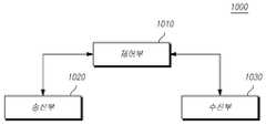
도 3은 또 다른 실시예에 의한 기지국(1000)의 구성을 보여주는 도면이다.3 is a diagram illustrating a configuration of a
도 3을 참조하면, 또 다른 실시예에 의한 기지국(1000)은 제어부(1010)과 송신부(1020), 수신부(1030)를 포함한다.Referring to FIG. 3, the
제어부(1010)는 전술한 본 발명을 수행하기에 필요한 차세대 무선 액세스망에서 하향 링크 제어 채널을 반복 전송하는 방법에 있어서, 각각의 검색 공간(search space)별로 하향 링크 제어 채널의 반복 전송 횟수가 결정되는 것을 특징으로 하는 방법에 따른 전반적인 기지국(1000)의 동작을 제어한다.In the method for repeatedly transmitting the downlink control channel in the next generation wireless access network required to perform the present invention, the
송신부(1020)와 수신부(1030)는 전술한 본 발명을 수행하기에 필요한 신호나 메시지, 데이터를 단말과 송수신하는데 사용된다.The
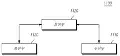
도 4는 또 다른 실시예에 의한 사용자 단말(1100)의 구성을 보여주는 도면이다.4 is a diagram illustrating a configuration of a
도 4를 참조하면, 또 다른 실시예에 의한 사용자 단말(1100)은 수신부(1110) 및 제어부(1120), 송신부(1130)를 포함한다.Referring to FIG. 4, the
수신부(1110)는 기지국으로부터 하향링크 제어 정보 및 데이터, 메시지를 해당 채널을 통해 수신한다.The
또한 제어부(1120)는 전술한 본 발명을 수행하기에 필요한 차세대 무선 액세스망에서 하향 링크 제어 채널을 반복 전송하는 방법에 있어서, 각각의 검색 공간(search space)별로 하향 링크 제어 채널의 반복 전송 횟수가 결정되는 것을 특징으로 하는 방법에 따른 전반적인 사용자 단말(1100)의 동작을 제어한다.In addition, the
송신부(1130)는 기지국에 상향링크 제어 정보 및 데이터, 메시지를 해당 채널을 통해 전송한다.The
전술한 실시예에서 언급한 표준내용 또는 표준문서들은 명세서의 설명을 간략하게 하기 위해 생략한 것으로 본 명세서의 일부를 구성한다. 따라서, 위 표준내용 및 표준문서들의 일부의 내용을 본 명세서에 추가하거나 청구범위에 기재하는 것은 본 발명의 범위에 해당하는 것으로 해석되어야 한다.The standard contents or standard documents mentioned in the above embodiments are omitted to simplify the description of the specification and form a part of the present specification. Therefore, the addition of the contents of the standard and part of the standard documents to the specification or the description in the claims should be interpreted as falling within the scope of the present invention.
이상의 설명은 본 발명의 기술 사상을 예시적으로 설명한 것에 불과한 것으로서, 본 발명이 속하는 기술 분야에서 통상의 지식을 가진 자라면 본 발명의 본질적인 특성에서 벗어나지 않는 범위에서 다양한 수정 및 변형이 가능할 것이다. 따라서, 본 발명에 개시된 실시예들은 본 발명의 기술 사상을 한정하기 위한 것이 아니라 설명하기 위한 것이고, 이러한 실시예에 의하여 본 발명의 기술사상의 범위가 한정되는 것은 아니다. 본 발명의 보호 범위는 아래의 청구범위에 의하여 해석되어야 하며, 그와 동등한 범위 내에 있는 모든 기술 사상은 본 발명의 권리범위에 포함되는 것으로 해석되어야 할 것이다.The above description is merely illustrative of the technical idea of the present invention, and those skilled in the art to which the present invention pertains may make various modifications and changes without departing from the essential characteristics of the present invention. Therefore, the embodiments disclosed in the present invention are not intended to limit the technical spirit of the present invention but to describe the present invention, and the scope of the technical idea of the present invention is not limited by these embodiments. The protection scope of the present invention should be interpreted by the following claims, and all technical ideas within the equivalent scope should be interpreted as being included in the scope of the present invention.
Claims (1)
Translated fromKorean각각의 검색 공간(search space)별로 하향 링크 제어 채널의 반복 전송 횟수가 결정되는 것을 특징으로 하는 방법.A method for repeatedly transmitting a downlink control channel in a next generation wireless access network,
Method for repetitive transmission of the downlink control channel is determined for each search space (search space).
Priority Applications (1)
| Application Number | Priority Date | Filing Date | Title |
|---|---|---|---|
| KR1020180033281AKR20190111307A (en) | 2018-03-22 | 2018-03-22 | Methods for transmitting PDCCH repeatedly for new radio and Apparatuses thereof |
Applications Claiming Priority (1)
| Application Number | Priority Date | Filing Date | Title |
|---|---|---|---|
| KR1020180033281AKR20190111307A (en) | 2018-03-22 | 2018-03-22 | Methods for transmitting PDCCH repeatedly for new radio and Apparatuses thereof |
Publications (1)
| Publication Number | Publication Date |
|---|---|
| KR20190111307Atrue KR20190111307A (en) | 2019-10-02 |
Family
ID=68422722
Family Applications (1)
| Application Number | Title | Priority Date | Filing Date |
|---|---|---|---|
| KR1020180033281AWithdrawnKR20190111307A (en) | 2018-03-22 | 2018-03-22 | Methods for transmitting PDCCH repeatedly for new radio and Apparatuses thereof |
Country Status (1)
| Country | Link |
|---|---|
| KR (1) | KR20190111307A (en) |
Cited By (5)
| Publication number | Priority date | Publication date | Assignee | Title |
|---|---|---|---|---|
| CN114070531A (en)* | 2020-08-07 | 2022-02-18 | 展讯通信(上海)有限公司 | PDCCH repeated configuration determination method and related product |
| CN114586400A (en)* | 2019-10-31 | 2022-06-03 | 华为技术有限公司 | A communication method and device |
| US20220304011A1 (en)* | 2020-05-15 | 2022-09-22 | Apple Inc. | Control Signaling for Physical Control Channel Reliability Enhancement |
| CN115669153A (en)* | 2020-08-07 | 2023-01-31 | Oppo广东移动通信有限公司 | Resource collection configuration method, device, equipment and storage medium |
| US12395996B2 (en) | 2020-07-28 | 2025-08-19 | Comcast Cable Communications, Llc | Control channel repetition using multiple coresets |
- 2018
- 2018-03-22KRKR1020180033281Apatent/KR20190111307A/ennot_activeWithdrawn
Cited By (9)
| Publication number | Priority date | Publication date | Assignee | Title |
|---|---|---|---|---|
| CN114586400A (en)* | 2019-10-31 | 2022-06-03 | 华为技术有限公司 | A communication method and device |
| EP4040835A4 (en)* | 2019-10-31 | 2022-10-19 | Huawei Technologies Co., Ltd. | COMMUNICATION METHOD AND DEVICE |
| CN114586400B (en)* | 2019-10-31 | 2024-03-26 | 华为技术有限公司 | A communication method and device |
| US12369161B2 (en) | 2019-10-31 | 2025-07-22 | Huawei Technologies Co., Ltd. | Communication method and apparatus |
| US20220304011A1 (en)* | 2020-05-15 | 2022-09-22 | Apple Inc. | Control Signaling for Physical Control Channel Reliability Enhancement |
| US12395996B2 (en) | 2020-07-28 | 2025-08-19 | Comcast Cable Communications, Llc | Control channel repetition using multiple coresets |
| CN114070531A (en)* | 2020-08-07 | 2022-02-18 | 展讯通信(上海)有限公司 | PDCCH repeated configuration determination method and related product |
| CN115669153A (en)* | 2020-08-07 | 2023-01-31 | Oppo广东移动通信有限公司 | Resource collection configuration method, device, equipment and storage medium |
| CN114070531B (en)* | 2020-08-07 | 2023-08-22 | 展讯通信(上海)有限公司 | PDCCH repeated configuration determining method and related products |
Similar Documents
| Publication | Publication Date | Title |
|---|---|---|
| US20240008048A1 (en) | Method and device for transmitting or receiving data in next generation wireless access network | |
| CN109600212B (en) | Apparatus and method for transmitting and receiving HARQ ACK/NACK information of new radio | |
| CN109586883B (en) | Apparatus and method for uplink control channel resource allocation for new radio | |
| US11765735B2 (en) | Method and device for transmitting or receiving data in next generation wireless access network | |
| KR102102319B1 (en) | Apparatus and method of transmitting and receiving HARQ ACK/NACK feedback information for new radio | |
| KR20190132183A (en) | Methods for transmitting PUCCH in new radio of unlicensed spectrum and Apparatuses thereof | |
| KR102222396B1 (en) | Methods for configuring frequency resource about component carrier for new radio and Apparatuses thereof | |
| KR102057127B1 (en) | Method for scheduling PUCCH for new radio and Apparatuses thereof | |
| KR20190111307A (en) | Methods for transmitting PDCCH repeatedly for new radio and Apparatuses thereof | |
| US20190268901A1 (en) | Method and apparatus for transmitting and receiving uplink control data in next generation wireless network | |
| KR102117970B1 (en) | Methods for monitoring, transmitting and receiving a downlink preemption indication for new radio networks and Apparatuses thereof | |
| KR102043996B1 (en) | Methods for transmitting and receiving a downlink preemption indication using bitmap for new radio networks and Apparatuses thereof | |
| KR102130999B1 (en) | MAethods of scheduling request based on multi-beam in wireless networks and Apparatuses thereof | |
| KR20180108940A (en) | Apparatus and method of DL control information monitoring for NR UEs | |
| CN110114997B (en) | Method and apparatus for allocating data channel resources for next generation wireless access network | |
| KR102114096B1 (en) | Methods for transmitting and receiving downlink control channel for new radio and Apparatuses thereof | |
| KR102246988B1 (en) | Apparatus and method of PUCCH resource allocation for new radio | |
| KR20180107417A (en) | Apparatus and method of DL HARQ operation for new radio | |
| KR102198758B1 (en) | Method for scheduling data channel in new radio and Apparatuses thereof | |
| KR20190085820A (en) | Methods for data modulation and coding for new radio and Appratuses thereof | |
| KR20190028262A (en) | Apparatus and method of uplink control information piggyback on PUSCH for new radio | |
| KR20190131831A (en) | Method for retransmitting data in new radio of unlicensed spectrum and Apparatuses thereof | |
| KR20200039855A (en) | Method for measuring sidelink channel state information in new radio and Apparatus thereof | |
| KR20180090429A (en) | Apparatus and method of downlink control channel transmission and reception for NR(New Radio) UEs | |
| KR102195869B1 (en) | Methods for transmitting and receiving a uplink control information for New radio network and Apparatuses thereof |
Legal Events
| Date | Code | Title | Description |
|---|---|---|---|
| PA0109 | Patent application | Patent event code:PA01091R01D Comment text:Patent Application Patent event date:20180322 | |
| PG1501 | Laying open of application | ||
| PC1203 | Withdrawal of no request for examination |