KR20190101301A - Construction method of database for pellicle membrane inspection and Method of inspecting pellicle membrane using the database - Google Patents
Construction method of database for pellicle membrane inspection and Method of inspecting pellicle membrane using the databaseDownload PDFInfo
- Publication number
- KR20190101301A KR20190101301AKR1020190020824AKR20190020824AKR20190101301AKR 20190101301 AKR20190101301 AKR 20190101301AKR 1020190020824 AKR1020190020824 AKR 1020190020824AKR 20190020824 AKR20190020824 AKR 20190020824AKR 20190101301 AKR20190101301 AKR 20190101301A
- Authority
- KR
- South Korea
- Prior art keywords
- pellicle
- light
- pellicle membrane
- defect
- euv
- Prior art date
- Legal status (The legal status is an assumption and is not a legal conclusion. Google has not performed a legal analysis and makes no representation as to the accuracy of the status listed.)
- Granted
Links
- 239000012528membraneSubstances0.000titleclaimsabstractdescription178
- 238000000034methodMethods0.000titleclaimsabstractdescription66
- 238000007689inspectionMethods0.000titleclaimsabstractdescription51
- 238000010276constructionMethods0.000title1
- 230000007547defectEffects0.000claimsabstractdescription146
- 230000001678irradiating effectEffects0.000claimsabstractdescription33
- 238000012360testing methodMethods0.000claimsdescription9
- 239000010409thin filmSubstances0.000description16
- 239000000356contaminantSubstances0.000description10
- 238000003384imaging methodMethods0.000description9
- 238000011109contaminationMethods0.000description6
- 230000003287optical effectEffects0.000description5
- 238000001514detection methodMethods0.000description4
- 239000004065semiconductorSubstances0.000description4
- 230000005540biological transmissionEffects0.000description3
- 230000000694effectsEffects0.000description3
- 238000004519manufacturing processMethods0.000description3
- 239000002245particleSubstances0.000description3
- 238000002834transmittanceMethods0.000description3
- 238000000825ultraviolet detectionMethods0.000description3
- 230000008033biological extinctionEffects0.000description2
- 230000002950deficientEffects0.000description2
- 239000000463materialSubstances0.000description2
- 238000010926purgeMethods0.000description2
- 238000012546transferMethods0.000description2
- 238000004140cleaningMethods0.000description1
- 230000000295complement effectEffects0.000description1
- 238000005516engineering processMethods0.000description1
- 238000011156evaluationMethods0.000description1
- 239000010408filmSubstances0.000description1
- 230000004941influxEffects0.000description1
- 238000012986modificationMethods0.000description1
- 230000004048modificationEffects0.000description1
- 230000007261regionalizationEffects0.000description1
- 238000011160researchMethods0.000description1
- 229910052709silverInorganic materials0.000description1
- 239000004332silverSubstances0.000description1
Images


Classifications
- G—PHYSICS
- G03—PHOTOGRAPHY; CINEMATOGRAPHY; ANALOGOUS TECHNIQUES USING WAVES OTHER THAN OPTICAL WAVES; ELECTROGRAPHY; HOLOGRAPHY
- G03F—PHOTOMECHANICAL PRODUCTION OF TEXTURED OR PATTERNED SURFACES, e.g. FOR PRINTING, FOR PROCESSING OF SEMICONDUCTOR DEVICES; MATERIALS THEREFOR; ORIGINALS THEREFOR; APPARATUS SPECIALLY ADAPTED THEREFOR
- G03F1/00—Originals for photomechanical production of textured or patterned surfaces, e.g., masks, photo-masks, reticles; Mask blanks or pellicles therefor; Containers specially adapted therefor; Preparation thereof
- G03F1/62—Pellicles, e.g. pellicle assemblies, e.g. having membrane on support frame; Preparation thereof
- G—PHYSICS
- G03—PHOTOGRAPHY; CINEMATOGRAPHY; ANALOGOUS TECHNIQUES USING WAVES OTHER THAN OPTICAL WAVES; ELECTROGRAPHY; HOLOGRAPHY
- G03F—PHOTOMECHANICAL PRODUCTION OF TEXTURED OR PATTERNED SURFACES, e.g. FOR PRINTING, FOR PROCESSING OF SEMICONDUCTOR DEVICES; MATERIALS THEREFOR; ORIGINALS THEREFOR; APPARATUS SPECIALLY ADAPTED THEREFOR
- G03F1/00—Originals for photomechanical production of textured or patterned surfaces, e.g., masks, photo-masks, reticles; Mask blanks or pellicles therefor; Containers specially adapted therefor; Preparation thereof
- G03F1/66—Containers specially adapted for masks, mask blanks or pellicles; Preparation thereof
- G—PHYSICS
- G03—PHOTOGRAPHY; CINEMATOGRAPHY; ANALOGOUS TECHNIQUES USING WAVES OTHER THAN OPTICAL WAVES; ELECTROGRAPHY; HOLOGRAPHY
- G03F—PHOTOMECHANICAL PRODUCTION OF TEXTURED OR PATTERNED SURFACES, e.g. FOR PRINTING, FOR PROCESSING OF SEMICONDUCTOR DEVICES; MATERIALS THEREFOR; ORIGINALS THEREFOR; APPARATUS SPECIALLY ADAPTED THEREFOR
- G03F7/00—Photomechanical, e.g. photolithographic, production of textured or patterned surfaces, e.g. printing surfaces; Materials therefor, e.g. comprising photoresists; Apparatus specially adapted therefor
- G03F7/70—Microphotolithographic exposure; Apparatus therefor
- G03F7/70008—Production of exposure light, i.e. light sources
- G03F7/70033—Production of exposure light, i.e. light sources by plasma extreme ultraviolet [EUV] sources
- G—PHYSICS
- G03—PHOTOGRAPHY; CINEMATOGRAPHY; ANALOGOUS TECHNIQUES USING WAVES OTHER THAN OPTICAL WAVES; ELECTROGRAPHY; HOLOGRAPHY
- G03F—PHOTOMECHANICAL PRODUCTION OF TEXTURED OR PATTERNED SURFACES, e.g. FOR PRINTING, FOR PROCESSING OF SEMICONDUCTOR DEVICES; MATERIALS THEREFOR; ORIGINALS THEREFOR; APPARATUS SPECIALLY ADAPTED THEREFOR
- G03F7/00—Photomechanical, e.g. photolithographic, production of textured or patterned surfaces, e.g. printing surfaces; Materials therefor, e.g. comprising photoresists; Apparatus specially adapted therefor
- G03F7/70—Microphotolithographic exposure; Apparatus therefor
- G03F7/70483—Information management; Active and passive control; Testing; Wafer monitoring, e.g. pattern monitoring
- G03F7/70491—Information management, e.g. software; Active and passive control, e.g. details of controlling exposure processes or exposure tool monitoring processes
- G03F7/70508—Data handling in all parts of the microlithographic apparatus, e.g. handling pattern data for addressable masks or data transfer to or from different components within the exposure apparatus
- G—PHYSICS
- G03—PHOTOGRAPHY; CINEMATOGRAPHY; ANALOGOUS TECHNIQUES USING WAVES OTHER THAN OPTICAL WAVES; ELECTROGRAPHY; HOLOGRAPHY
- G03F—PHOTOMECHANICAL PRODUCTION OF TEXTURED OR PATTERNED SURFACES, e.g. FOR PRINTING, FOR PROCESSING OF SEMICONDUCTOR DEVICES; MATERIALS THEREFOR; ORIGINALS THEREFOR; APPARATUS SPECIALLY ADAPTED THEREFOR
- G03F7/00—Photomechanical, e.g. photolithographic, production of textured or patterned surfaces, e.g. printing surfaces; Materials therefor, e.g. comprising photoresists; Apparatus specially adapted therefor
- G03F7/70—Microphotolithographic exposure; Apparatus therefor
- G03F7/70483—Information management; Active and passive control; Testing; Wafer monitoring, e.g. pattern monitoring
- G03F7/70591—Testing optical components
- G—PHYSICS
- G03—PHOTOGRAPHY; CINEMATOGRAPHY; ANALOGOUS TECHNIQUES USING WAVES OTHER THAN OPTICAL WAVES; ELECTROGRAPHY; HOLOGRAPHY
- G03F—PHOTOMECHANICAL PRODUCTION OF TEXTURED OR PATTERNED SURFACES, e.g. FOR PRINTING, FOR PROCESSING OF SEMICONDUCTOR DEVICES; MATERIALS THEREFOR; ORIGINALS THEREFOR; APPARATUS SPECIALLY ADAPTED THEREFOR
- G03F7/00—Photomechanical, e.g. photolithographic, production of textured or patterned surfaces, e.g. printing surfaces; Materials therefor, e.g. comprising photoresists; Apparatus specially adapted therefor
- G03F7/70—Microphotolithographic exposure; Apparatus therefor
- G03F7/70483—Information management; Active and passive control; Testing; Wafer monitoring, e.g. pattern monitoring
- G03F7/70605—Workpiece metrology
- G03F7/70616—Monitoring the printed patterns
- G03F7/7065—Defects, e.g. optical inspection of patterned layer for defects
Landscapes
- Physics & Mathematics (AREA)
- General Physics & Mathematics (AREA)
- Engineering & Computer Science (AREA)
- Plasma & Fusion (AREA)
- Investigating Materials By The Use Of Optical Means Adapted For Particular Applications (AREA)
- Preparing Plates And Mask In Photomechanical Process (AREA)
Abstract
Translated fromKoreanDescription
Translated fromKorean본 발명은 펠리클 멤브레인의 검사 데이터베이스 구축 방법 및 그 데이터베이스를 이용한 펠리클 멤브레인의 검사 방법에 관련된 것으로, 상세하게는, UV(ultraviolet) 광 및 EUV(extreme ultraviolet) 광에 의해 검출된 펠리클 멤브레인의 결함들에 대한 검사 데이터베이스 구축 방법, 및 그 데이터베이스를 이용한 펠리클 멤브레인의 검사 방법과 관련된 것이다.The present invention relates to a method for constructing an inspection database of a pellicle membrane and a method for inspecting a pellicle membrane using the database. Specifically, the present invention relates to defects of a pellicle membrane detected by ultraviolet (UV) light and extreme ultraviolet (EUV) light. And a method for establishing a test database for the pellicle membrane.
EUV(extreme ultraviolet) 노광 공정은 수 나노미터 이하 노드 반도체(node semiconductor) 양산 공정에 적용 가능한 유일한 차세대 반도체 노광 기술이다. 상기 EUV 노광 공정에서 사용되는 13.5 nm의 파장은, 종래의 노광 공정에서 사용되는 193 nm의 파장과는 다르게, 자연계의 대부분의 물질에서 높은 소광계수를 나타낸다. 이러한 EUV 광의 특성으로 인하여, 노광 공정 중에 발생하는 결함이나 오염은 패턴 형성과정에서 치명적인 영향을 미칠 수 있다. 상기 EUV 노광 공정의 성공적인 양산을 위해서는, 공정 상의 수율 향상이 필수적이기 때문에, 공정 중 발생하는 오염물질의 유입을 방지하여 마스크의 오염을 막는 펠리클의 개발이 반드시 필요하다.EUV (extreme ultraviolet) exposure process is the only next-generation semiconductor exposure technology that can be applied to the mass production of node semiconductors of several nanometers or less. The wavelength of 13.5 nm used in the EUV exposure process shows a high extinction coefficient in most materials of nature, unlike the wavelength of 193 nm used in the conventional exposure process. Due to the characteristics of EUV light, defects or contaminations generated during the exposure process may have a fatal effect in the pattern formation process. In order to successfully mass-produce the EUV exposure process, it is essential to improve the yield of the process, and thus, it is necessary to develop a pellicle that prevents contamination of the mask by preventing the influx of contaminants generated during the process.
현재까지 EUV 노광 공정용 펠리클은 초기 연구 단계에 있으며, 상기 EUV 노광 공정용 펠리클의 기본 특성에 대한 검사 기술 조차 확립되지 않은 상태이다. 이러한 이유로, 종래에는 UV(ultraviolet)를 이용해 노광 공정용 펠리클 및 마스크를 검사하는 방법이 사용되고 있다. 예를 들어, 대한민국 특허 등록 공보 KR100719373B1(출원번호: 10-2005-0073884, 출원인: 삼성전자주식회사)에는, 레티클과 펠리클이 분리되어 상기 레티클은 레티클 척의 상면에 탑재되고 상기 펠리클은 상기 레티클 척의 하면에 탈착가능하게 고정된 레티클 스테이지를 이용한 펠리클 검사 방법에 있어서, 상기 레티클에 UV를 조사하여 웨이퍼를 노광하는 단계, 상기 레티클과 상기 펠리클 사이의 공간에 퍼징 가스를 도입시켜 상기 공간을 퍼징시키는 단계, 상기 레티클을 상기 레티클 척으로부터 분리시켜 세정하는 단계, 상기 펠리클을 상기 레티클 척으로부터 분리시키는 단계, 상기 펠리클의 UV 투과율을 검사하는 단계와 상기 펠리클의 UV 투과율이 양호한 경우 상기 펠리클을 상기 레티클 척의 하면으로 이동시켜 고정시키는 단계, 및 상기 펠리클의 UV 투과율이 불량한 경우 상기 펠리클을 교체하는 단계를 포함하는 펠리클 검사 방법이 개시되어 있다.To date, pellicles for EUV exposure processes are in the early stages of research, and even inspection techniques for the basic properties of the pellicles for EUV exposure processes have not been established. For this reason, a method of inspecting a pellicle and a mask for an exposure process using UV (ultraviolet) is conventionally used. For example, in Korean Patent Registration Publication KR100719373B1 (Application No .: 10-2005-0073884, Applicant: Samsung Electronics Co., Ltd.), a reticle and a pellicle are separated so that the reticle is mounted on the upper surface of the reticle chuck and the pellicle is on the lower surface of the reticle chuck. A pellicle inspection method using a detachably fixed reticle stage, the method comprising: exposing a wafer by irradiating UV to the reticle, introducing a purging gas into a space between the reticle and the pellicle and purging the space; Separating and cleaning the reticle from the reticle chuck, separating the pellicle from the reticle chuck, examining the UV transmittance of the pellicle and moving the pellicle to the bottom surface of the reticle chuck if the pellicle has good UV transmission. Fixation, and UV transmission of the pellicle If the poor discloses a pellicle inspection method comprising the step of replacing the pellicle.
그러나, 상술된 바와 같이, 자연계의 대부분의 물질에서 높은 소광계수를 나타내는, 상기 EUV 광의 독특한 특성으로 인하여, 종래의 노광 공정에 사용되는 193 nm 파장을 이용하는 것은, 상기 EUV 노광 공정용 펠리클의 성능을 평가하는 데에 한계가 있다. 상기 EUV 노광 공정용 펠리클은, 상기 EUV 광에 대한 투과만 가능하도록 설계되었기 때문에, 노광 파장과 같은 파장인 13.5 nm의 EUV 광을 사용하는 경우에 한해서, 상기 EUV 노광 공정용 펠리클에 대한 정확한 검사가 가능하다. 이는 EUV 노광 공정이 반도체 양산 공정에 적용되기 위해서는 반드시 선행 연구되어야 하는 기술이다.However, as described above, due to the unique characteristics of the EUV light, which exhibits a high extinction coefficient in most materials of nature, using the 193 nm wavelength used in conventional exposure processes is a measure of the performance of the pellicle for EUV exposure processes. There is a limit to the evaluation. Since the pellicle for the EUV exposure process is designed to transmit only the EUV light, only when EUV light having the same wavelength as the exposure wavelength is used, the pellicle for the EUV exposure process is accurate. It is possible. This is a technique that must be studied before the EUV exposure process can be applied to the semiconductor mass production process.
EUV 광을 이용해, 펠리클 멤브레인을 포함하는 펠리클을 검사하는 기술은, 결함 검출 성능에 있어서 탁월하지만, 좁은 검사 면적과 느린 검사 속도로 인해 생산성 면에서 한계가 존재한다. 이에 따라, 펠리클 멤브레인의 대면적을 고속으로 정확하게 검사하는 방법이 필요한 실정이다.Techniques for inspecting pellicles containing pellicle membranes, using EUV light, are excellent in defect detection performance, but there are limitations in productivity due to their narrow inspection area and slow inspection speed. Accordingly, there is a need for a method of accurately and accurately inspecting a large area of a pellicle membrane at high speed.
본 발명이 해결하고자 하는 일 기술적 과제는, UV(ultraviolet) 광에 의해 검출된 결함들 중에서, EUV(extreme ultraviolet) 광에 의해 검출된 결함은 제1 타입 결함으로 분류하고, 상기 EUV 광에 의해 검출되지 않은 결함은 제2 타입 결함으로 분류하여 저장하는 펠리클 멤브레인의 검사 데이터베이스 구축 방법 및 그 데이터베이스를 이용한 펠리클 멤브레인의 검사 방법을 제공하는 데 있다.One technical problem to be solved by the present invention is, among the defects detected by UV (ultraviolet) light, defects detected by extreme ultraviolet (EUV) light is classified as a first type defect, and detected by the EUV light The non-defective defect is to provide a method for constructing an inspection database of a pellicle membrane which is classified and stored as a second type defect, and a method for inspecting a pellicle membrane using the database.
본 발명이 해결하고자 하는 다른 기술적 과제는, UV 광에 의한 검사만으로도, EUV 광에 의해 검출되는 펠리클 멤브레인의 결함들에 대한 예측이 가능한 펠리클 멤브레인의 검사 데이터베이스 구축 방법 및 그 데이터베이스를 이용한 펠리클 멤브레인의 검사 방법을 제공하는 데 있다.Another technical problem to be solved by the present invention is a method for constructing an inspection database of a pellicle membrane that can predict defects of a pellicle membrane detected by EUV light only by inspection by UV light, and inspection of a pellicle membrane using the database. To provide a way.
본 발명이 해결하고자 하는 또 다른 기술적 과제는, 대면적을 고속으로 정확하게 검사하는 것이 가능한 펠리클 멤브레인의 검사 데이터베이스 구축 방법 및 그 데이터베이스를 이용한 펠리클 멤브레인의 검사 방법을 제공하는 데 있다.Another technical problem to be solved by the present invention is to provide a method for constructing an inspection database of a pellicle membrane capable of inspecting a large area accurately and at high speed, and a method for inspecting a pellicle membrane using the database.
본 발명이 해결하고자 하는 또 다른 기술적 과제는, 시간 및 비용을 절약할 수 있어, 경제성 및 생산성이 향상된 펠리클 멤브레인의 검사 데이터베이스 구축 방법 및 그 데이터베이스를 이용한 펠리클 멤브레인의 검사 방법을 제공하는 데 있다.Another technical problem to be solved by the present invention is to provide a method for constructing a test database of a pellicle membrane and a method for inspecting a pellicle membrane using the database, which can save time and cost, thereby improving economics and productivity.
본 발명이 해결하고자 하는 기술적 과제는 상술된 것에 제한되지 않는다.The technical problem to be solved by the present invention is not limited to the above.
상술된 기술적 과제를 해결하기 위해, 본 발명은 펠리클 멤브레인의 검사 데이터베이스 구축 방법을 제공한다.In order to solve the above technical problem, the present invention provides a method for establishing a test database of the pellicle membrane.
일 실시 예에 따르면, 상기 펠리클 멤브레인의 검사 데이터베이스 구축 방법은, 펠리클 멤브레인을 포함하는 펠리클을 준비하는 단계, 상기 펠리클 멤브레인에 UV(ultraviolet) 광을 조사하여, 상기 펠리클 멤브레인의 결함들을 검출하는 단계, 상기 펠리클 멤브레인에 EUV(extreme ultraviolet) 광을 조사하여, 상기 펠리클 멤브레인의 결함들을 검출하는 단계, 및 상기 UV 광에 의해 검출된 결함들 중에서, 상기 EUV 광에 의해 검출된 결함은 제1 타입 결함으로 분류하고, 상기 EUV 광에 의해 검출되지 않은 결함은 제2 타입 결함으로 분류하여 저장하는 단계를 포함할 수 있다.According to one embodiment, the method for building a test database of the pellicle membrane, preparing a pellicle comprising a pellicle membrane, irradiating UV (ultraviolet) light to the pellicle membrane, detecting the defects of the pellicle membrane, Irradiating EUV (extreme ultraviolet) light to the pellicle membrane to detect defects of the pellicle membrane, and among the defects detected by the UV light, the defect detected by the EUV light is a first type defect. And classifying and storing the defect not detected by the EUV light may be classified as a second type defect.
일 실시 예에 따르면, 상기 EUV 광이 상기 펠리클 멤브레인에 조사되는 면적보다, 상기 UV 광이 상기 펠리클 멤브레인에 조사되는 면적이 더 넓을 수 있다.According to an embodiment, the area irradiated with the pellicle membrane may be larger than the area irradiated with the pellicle membrane with the EUV light.
일 실시 예에 따르면, 상기 펠리클 멤브레인에 상기 UV 광을 선형으로 조사할 수 있다.According to one embodiment, the pellicle membrane may be linearly irradiated with the UV light.
일 실시 예에 따르면, 복수의 LED(light emitting diode) 광원 유닛이 일렬로 배치된, LED 모듈에 의해 상기 UV 광이 선형으로 조사될 수 있다.According to an embodiment of the present disclosure, the UV light may be linearly radiated by an LED module in which a plurality of light emitting diode (LED) light source units are arranged in a line.
일 실시 예에 따르면, 상기 EUV 광이 상기 펠리클 멤브레인에 조사되는 시간보다, 상기 UV 광이 상기 펠리클 멤브레인에 조사되는 시간이 더 짧을 수 있다.According to one embodiment, the time that the UV light is irradiated on the pellicle membrane may be shorter than the time when the EUV light is irradiated on the pellicle membrane.
일 실시 예에 따르면, 상기 펠리클 멤브레인의 결함들은, 결함 종류, 크기 또는 위치 중 적어도 어느 하나에 따라 상기 제1 타입 결함 및 상기 제2 타입 결함으로 구별되어 데이터베이스로 저장될 수 있다.According to an embodiment of the present disclosure, the defects of the pellicle membrane may be classified into the first type defect and the second type defect and stored in a database according to at least one of a defect type, a size, or a location.
일 실시 예에 따르면, 상기 펠리클은 이동 가능한 스테이지 상에 배치되고, 상기 스테이지의 이동에 따라, 상기 펠리클 멤브레인의 결함이 영상으로 검출될 수 있다.According to one embodiment, the pellicle is disposed on the movable stage, the defect of the pellicle membrane can be detected as an image according to the movement of the stage.
또한, 상술된 기술적 과제를 해결하기 위해, 본 발명은 데이터베이스를 이용한 펠리클 멤브레인의 검사 방법을 제공한다In addition, in order to solve the above technical problem, the present invention provides a method for inspecting a pellicle membrane using a database.
일 실시 예에 따르면, 데이터베이스를 이용한 펠리클 멤브레인의 검사 방법은, UV 광 및 EUV 광에 의해 검출 가능한 제1 타입 결함, 및 상기 UV 광에 의해 검출되고 상기 EUV 광에 의해 검출되지 않는 제2 타입 결함에 대한 정보를 갖는 데이터 베이스를 준비하는 단계, 펠리클 멤브레인을 포함하는 펠리클을 준비하는 단계, 상기 펠리클 멤브레인에 상기 UV 광을 조사하여 결함을 검출하는 단계, 및 상기 UV 광에 의해 검출된 결함이 상기 제1 타입 결함 또는 상기 제2 타입 결함 중에서 어느 것에 해당되는지 판단하는 단계를 포함할 수 있다.According to one embodiment, a method for inspecting a pellicle membrane using a database includes a first type defect detectable by UV light and EUV light, and a second type defect detected by the UV light and not detected by the EUV light. Preparing a database having information about the method, preparing a pellicle including a pellicle membrane, detecting the defect by irradiating the pellicle membrane with the UV light, and detecting the defect detected by the UV light. The method may include determining which one corresponds to the first type defect or the second type defect.
일 실시 예에 따르면, 상기 제1 타입 결함으로 분류되는 경우, 최종적 결함인 것으로 판단될 수 있다.According to one embodiment, when classified as the first type defect, it may be determined that the final defect.
일 실시 예에 따르면, 상기 제2 타입 결함으로 분류되는 경우, 최종적 결함이 아닌 것으로 판단될 수 있다.According to one embodiment, when classified as the second type defect, it may be determined that the final defect is not.
본 발명의 실시 예에 따르면, UV(ultraviolet) 광에 의해 검출된 결함들 중에서, EUV(extreme ultraviolet) 광에 의해 검출된 결함은 제1 타입 결함으로 분류하고, 상기 EUV 광에 의해 검출되지 않은 결함은 제2 타입 결함으로 분류하여 저장하는 펠리클 멤브레인의 검사 데이터베이스 구축 방법, 및 그 데이터베이스를 이용한 펠리클 멤브레인의 검사 방법이 제공될 수 있다.According to an embodiment of the present invention, among defects detected by ultraviolet (UV) light, defects detected by extreme ultraviolet (EUV) light are classified as first type defects and are not detected by the EUV light. A method for constructing an inspection database of a pellicle membrane for classifying and storing silver as a second type defect may be provided, and a method for inspecting a pellicle membrane using the database.
상기 제1 타입 및 제2 타입 결함으로 분류되는 펠리클 멤브레인의 검사 데이터베이스가 구축됨에 따라, 상기 데이터베이스를 이용해 EUV 광을 조사하지 않고도, UV 광을 조사하는 것만으로, 용이하게 EUV 광에 의해 검출되는 펠리클 멤브레인의 결함을 예측하는 것이 가능하다. 또한, 펠리클 멤브레인의 대면적을 고속으로 정확하게 검사하여, 시간 및 비용을 절약할 수 있어, 경제성 및 생산성이 향상되는 효과가 있다.As the inspection database of pellicle membranes classified into the first type and the second type defects is established, the pellicle can be easily detected by EUV light only by irradiating UV light without irradiating EUV light using the database. It is possible to predict defects in the membrane. In addition, by accurately inspecting the large area of the pellicle membrane at high speed, it is possible to save time and cost, thereby improving economics and productivity.
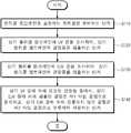
도 1은 본 발명의 실시 예에 따른 펠리클 멤브레인의 검사 데이터베이스 구축 방법을 설명하기 위한 순서도이다.
도 2는 본 발명의 실시 예에 따른 펠리클 멤브레인의 UV(ultraviolet) 검사 장치를 설명하기 위한 도면이다.
도 3은 본 발명의 실시 예에 따른 펠리클 멤브레인의 UV 검사 장치의 LED(light emitting diode) 모듈의 실사이다.
도 4는 본 발명의 실시 예에 따른 펠리클 멤브레인의 EUV(extreme ultraviolet) 검사 장치를 설명하기 위한 도면이다.
도 5는 본 발명의 실시 예에 따른 UV 검사 장치를 이용해 측정된 펠리클 멤브레인의 결함들을 나타내는 이미지이다.
도 6은 본 발명의 실시 예에 따른 EUV 검사 장치를 이용해 측정된 펠리클 멤브레인의 결함들을 나타내는 이미지이다.
도 7은 본 발명의 실시 예에 따른 데이터베이스를 이용한 펠리클 멤브레인의 검사 방법을 설명하기 위한 순서도이다.
도 8 및 도 9는 본 발명의 실시 예에 따른 UV 검사 장치의 성능을 나타내는 사진이다.
도 10 및 도 11은 본 발명의 실시 예에 따른 EUV 검사 장치의 성능을 나타내는 사진이다.
도 12 및 도 13은 오염된 펠리클이 마스크 패턴 이미징에 미치는 효과를 나타내는 사진 및 그래프이다.
도 14 및 도 15는 마스크 패턴 이미징에 영향을 미치는 펠리클 오염원의 임계 크기를 확인하는 사진이다.1 is a flowchart illustrating a method for constructing a test database of a pellicle membrane according to an embodiment of the present invention.
2 is a view for explaining a UV (ultraviolet) inspection apparatus of a pellicle membrane according to an embodiment of the present invention.
3 is a live-action of a light emitting diode (LED) module of the UV inspection apparatus of the pellicle membrane according to an embodiment of the present invention.
FIG. 4 is a view for explaining an EUV (extreme ultraviolet) inspection apparatus of a pellicle membrane according to an embodiment of the present invention.
5 is an image showing defects of the pellicle membrane measured using the UV inspection apparatus according to an embodiment of the present invention.
6 is an image showing defects of the pellicle membrane measured using the EUV inspection apparatus according to an embodiment of the present invention.
7 is a flowchart illustrating a method of inspecting a pellicle membrane using a database according to an embodiment of the present invention.
8 and 9 are photographs showing the performance of the UV inspection apparatus according to an embodiment of the present invention.
10 and 11 are photographs showing the performance of the EUV inspection apparatus according to an embodiment of the present invention.
12 and 13 are photographs and graphs showing the effect of contaminated pellicle on mask pattern imaging.
14 and 15 are photographs confirming the critical size of pellicle contaminants affecting mask pattern imaging.
이하, 첨부된 도면들을 참조하여 본 발명의 바람직한 실시 예를 상세히 설명할 것이다. 그러나 본 발명의 기술적 사상은 여기서 설명되는 실시 예에 한정되지 않고 다른 형태로 구체화 될 수도 있다. 오히려, 여기서 소개되는 실시 예는 개시된 내용이 철저하고 완전해질 수 있도록 그리고 당업자에게 본 발명의 사상이 충분히 전달될 수 있도록 하기 위해 제공되는 것이다.Hereinafter, exemplary embodiments of the present invention will be described in detail with reference to the accompanying drawings. However, the technical idea of the present invention is not limited to the exemplary embodiments described herein and may be embodied in other forms. Rather, the embodiments introduced herein are provided to ensure that the disclosed contents are thorough and complete, and that the spirit of the present invention can be sufficiently delivered to those skilled in the art.
본 명세서에서, 어떤 구성요소가 다른 구성요소 상에 있다고 언급되는 경우에 그것은 다른 구성요소 상에 직접 형성될 수 있거나 또는 그들 사이에 제 3의 구성요소가 개재될 수도 있다는 것을 의미한다. 또한, 도면들에 있어서, 막 및 영역들의 두께는 기술적 내용의 효과적인 설명을 위해 과장된 것이다.In the present specification, when a component is mentioned to be on another component, it means that it may be formed directly on the other component or a third component may be interposed therebetween. In addition, in the drawings, the thicknesses of films and regions are exaggerated for effective explanation of technical contents.
또한, 본 명세서의 다양한 실시 예 들에서 제1, 제2, 제3 등의 용어가 다양한 구성요소들을 기술하기 위해서 사용되었지만, 이들 구성요소들이 이 같은 용어들에 의해서 한정되어서는 안 된다. 이들 용어들은 단지 어느 구성요소를 다른 구성요소와 구별시키기 위해서 사용되었을 뿐이다. 따라서, 어느 한 실시 예에 제1 구성요소로 언급된 것이 다른 실시 예에서는 제2 구성요소로 언급될 수도 있다. 여기에 설명되고 예시되는 각 실시 예는 그것의 상보적인 실시 예도 포함한다. 또한, 본 명세서에서 '및/또는'은 전후에 나열한 구성요소들 중 적어도 어느 하나를 포함하는 의미로 사용되었다.In addition, in various embodiments of the present specification, terms such as first, second, and third are used to describe various components, but these components should not be limited by these terms. These terms are only used to distinguish one component from another. Therefore, what is referred to as a first component in one embodiment may be referred to as a second component in another embodiment. Each embodiment described and illustrated herein also includes its complementary embodiment. In addition, the term 'and / or' is used herein to include at least one of the components listed before and after.
명세서에서 단수의 표현은 문맥상 명백하게 다르게 뜻하지 않는 한 복수의 표현을 포함한다. 또한, "포함하다" 또는 "가지다" 등의 용어는 명세서상에 기재된 특징, 숫자, 단계, 구성요소 또는 이들을 조합한 것이 존재함을 지정하려는 것이지, 하나 또는 그 이상의 다른 특징이나 숫자, 단계, 구성요소 또는 이들을 조합한 것들의 존재 또는 부가 가능성을 배제하는 것으로 이해되어서는 안 된다.In the specification, the singular encompasses the plural unless the context clearly indicates otherwise. In addition, the terms "comprise" or "having" are intended to indicate that there is a feature, number, step, element, or combination thereof described in the specification, and one or more other features or numbers, steps, configurations It should not be understood to exclude the possibility of the presence or the addition of elements or combinations thereof.
또한, 하기에서 본 발명을 설명함에 있어 관련된 공지 기능 또는 구성에 대한 구체적인 설명이 본 발명의 요지를 불필요하게 흐릴 수 있다고 판단되는 경우에는 그 상세한 설명은 생략할 것이다.In addition, in the following description of the present invention, if it is determined that a detailed description of a related known function or configuration may unnecessarily obscure the subject matter of the present invention, the detailed description thereof will be omitted.
도 1은 본 발명의 실시 예에 따른 펠리클 멤브레인의 검사 데이터베이스 구축 방법을 설명하기 위한 순서도이고, 도 2는 본 발명의 실시 예에 따른 펠리클 멤브레인의 UV(ultraviolet) 검사 장치를 설명하기 위한 도면이고, 도 3은 본 발명의 실시 예에 따른 펠리클 멤브레인의 UV 검사 장치의 LED(light emitting diode) 모듈의 실사이고, 도 4는 본 발명의 실시 예에 따른 펠리클 멤브레인의 EUV(extreme ultraviolet) 검사 장치를 설명하기 위한 도면이다.1 is a flowchart illustrating a method for constructing a test database of a pellicle membrane according to an embodiment of the present invention, FIG. 2 is a view illustrating a UV (ultraviolet) test apparatus for a pellicle membrane according to an embodiment of the present invention. FIG. 3 is an actual inspection of a light emitting diode (LED) module of a UV inspection apparatus of a pellicle membrane according to an embodiment of the present invention, and FIG. 4 illustrates an EUV (extreme ultraviolet) inspection apparatus of a pellicle membrane according to an embodiment of the present invention. It is a figure for following.
도 1 내지 도 3을 참조하면, 펠리클 멤브레인을 포함하는 펠리클(100)을 준비할 수 있다(S110).1 to 3, a
상기 펠리클(100)은 제1 펠리클 스테이지(20) 상에 배치될 수 있다. 상기 제1 펠리클 스테이지(20)는, 제1 스테이지(21), 제1 지지부(22) 및 제2 지지부(23)를 포함할 수 있다.The
상기 제1 펠리클 스테이지(20)는, 상기 제2 지지부(23) 상에 상기 제1 지지부(22)가 제공되고, 상기 제1 지지부(22) 상에 상기 제1 스테이지(21)가 제공되어, 상기 제2 지지부(23), 상기 제1 지지부(22), 및 상기 제1 스테이지(21)가 차례로 적층된 구조로 배치될 수 있다. 일 실시 예에 따르면, 상기 제1 지지부(22)는 제1 방향(x 방향)으로 연장될 수 있고, 상기 제2 지지부(23)는 제2 방향(y 방향)으로 연장될 수 있다.In the
상기 펠리클(100)은, 상기 제1 펠리클 스테이지(20)의 상기 제1 스테이지(21)의 상부면 상에 직접 접촉되어 배치될 수 있다. 도 2에 도시된 바와 같이, 측정하고자 하는 상기 펠리클 멤브레인의 위치에 따라, 상기 제1 스테이지(21)가 상기 제1 지지부(22) 상에서, 상기 제1 방향(x 방향)으로 이동될 수 있다. 또한, 측정하고자 하는 상기 펠리클 멤브레인의 위치에 따라, 상기 제1 스테이지(21)가 상부면에 제공된 상기 제1 지지부(22)가, 상기 제2 지지부(23) 상에서, 상기 제2 방향(y 방향)으로 이동됨에 따라, 측정하고자 하는 상기 펠리클 멤브레인의 위치가 용이하게 조절될 수 있다.The
본 발명의 실시 예에 따르면, 상술된 바와 같이, 상기 펠리클(100)이, 상기 제1 및 제2 방향(x 방향 및 y 방향)으로 이동 가능한, 상기 제1 및 제2 지지부(22, 23)를 포함하는, 상기 제1 펠리클 스테이지(20) 상에 배치되고, 상기 제1 펠리클 스테이지(20) 상의 상기 제1 및 제2 지지부(22, 23)의 이동에 따라, 상기 펠리클 멤브레인의 결함들이 영상으로 검출되어, 상기 펠리클 멤브레인의 검사 데이터베이스를 용이하게 구축할 수 있다.According to an embodiment of the present invention, as described above, the
상기 펠리클 멤브레인에 UV 광을 조사하여, 상기 펠리클 멤브레인의 결함들을 검출할 수 있다(S120). 다시 말해, UV 광원부(10)에 의해 상기 펠리클 멤브레인에 상기 UV 광이 조사되고, UV 검출부(30)에 의해 상기 펠리클 멤브레인 상에서 반사 및 산란된 UV 광이 수집 및 측정될 수 있다. 구체적으로, 반사 및 산란된 상기 UV 광을 수집 및 측정하는 단계는, 상기 펠리클 멤브레인에 상기 UV 광을 조사하는 단계, 및 상기 UV 검출부(30)가 반사 및 산란된 상기 UV 광을 수집 및 측정하는 단계를 포함할 수 있다.UV light is irradiated onto the pellicle membrane to detect defects of the pellicle membrane (S120). In other words, the pellicle membrane is irradiated with the UV light by the UV
상기 펠리클 멤브레인에 상기 UV 광을 조사하는 단계는, 상기 UV 광원부(10)에서 발생된 상기 UV 광이 상기 펠리클 멤브레인에 조사되는 것을 포함할 수 있다. 상기 UV 광원부(10)에서 상기 펠리클 멤브레인에 조사되는 상기 UV 광의 파장은, 종래의 UV 노광 공정용 노광기에서 발생하는 광원의 파장과 동일할 수 있다. 일 실시 예에 따르면, 상기 UV 광원부(10)에서 발생된 상기 UV 광의 파장은, 약 365 nm일 수 있다.The irradiating the pellicle membrane with the UV light may include irradiating the pellicle membrane with the UV light generated by the UV
본 발명의 실시 예에 따르면, 도 3에 도시된 바와 같이, 상기 펠리클 멤브레인에 상기 UV 광을 조사하는 단계는, 복수의 LED 광원 유닛이 일렬로 배치된, LED 모듈에 의해 상기 UV 광이 선형으로 상기 펠리클 멤브레인에 조사되는 것을 포함할 수 있다. 이에 따라, 후술되는 EUV 광이 상기 펠리클 멤브레인에 조사되는 면적보다, 상기 UV 광이 상기 펠리클 멤브레인에 조사되는 면적이 더 넓을 수 있다. 또한, 후술되는 EUV 광이 상기 펠리클 멤브레인에 조사되는 시간보다, 상기 UV 광이 상기 펠리클 멤브레인에 조사되는 시간이 더 짧을 수 있다.According to an embodiment of the present invention, as shown in Figure 3, irradiating the UV light to the pellicle membrane, the UV light is linearly by the LED module, a plurality of LED light source units are arranged in a line It may include irradiated to the pellicle membrane. Accordingly, the area in which the UV light is irradiated to the pellicle membrane may be larger than the area in which EUV light described later is irradiated to the pellicle membrane. In addition, the time that the UV light is irradiated to the pellicle membrane may be shorter than the time when the EUV light described later is irradiated to the pellicle membrane.
다시 말해, 본 발명의 실시 예에 따른 상기 LED 모듈을 사용하는 경우, 상기 UV 광이 선형으로 상기 펠리클 멤브레인에 조사되는 것에 따라, 짧은 시간 내에 상기 펠리클 멤브레인의 대면적을 검사하는 것이 가능하므로, 상기 펠리클 멤브레인의 결함 검사에 있어서 시간 및 비용을 절약할 수 있어, 경제성이 향상될 수 있다.In other words, when using the LED module according to an embodiment of the present invention, as the UV light is linearly irradiated to the pellicle membrane, it is possible to inspect the large area of the pellicle membrane within a short time, It is possible to save time and money in defect inspection of the pellicle membrane, thereby improving economics.
또한 상기 UV 광원부(10)는, 상기 UV 광원부(10)로부터 상기 펠리클 멤브레인으로 조사되는 상기 UV 광의 경로, 및 상기 펠리클 멤브레인 상에서 상기 UV 검출부(30)로 산란되는 상기 UV 광의 경로에, 상기 UV 광의 경로 조절을 위한 광학 렌즈를 더 포함할 수 있다.In addition, the UV
상기 UV 검출부(30)가 상기 UV 광을 수집 및 측정하는 단계는, 상기 UV 검출부(30)에 의해, 상기 펠리클 멤브레인 상에서 반사 및 산란된 상기 UV 광의 발광강도가 측정되는 것을 포함할 수 있다. 상기 UV 검출부(30)에서 측정된 상기 UV 광의 상기 발광강도는, 후술되는 EUV 검출부(70)에서 측정된 EUV 광의 발광강도와 함께 본 발명의 실시 예에 따른 펠리클 멤브레인의 결함 검출에 이용될 수 있다.The collecting and measuring of the UV light by the
일 실시 예에 따르면, 상기 UV 검출부(30)는 대물 렌즈(objective lens), 영상 렌즈(image lens), 및 라인 카메라(line camera)를 포함할 수 있다.According to an embodiment of the present disclosure, the
도 1 및 도 4를 참조하면, 상기 펠리클 멤브레인에 EUV 광을 조사하여, 상기 펠리클 멤브레인의 결함들을 검출할 수 있다(S130).Referring to FIGS. 1 and 4, EUV light may be irradiated onto the pellicle membrane to detect defects of the pellicle membrane (S130).
본 발명의 실시 예에 따르면, 상기 펠리클 멤브레인에, 상기 UV 광을 조사하는 단계와, 상기 EUV 광을 조사하는 단계는 서로 다른 검사 장치에서 수행될 수 있다. 이에 따라, 상기 펠리클 멤브레인에 상기 UV 광을 조사하는 단계 이후에, 상기 페리클(100)은 상기 EUV 광을 조사하는 EUV 검사 장치로 이동될 수 있다.According to an embodiment of the present disclosure, irradiating the pellicle membrane with the UV light and irradiating the EUV light may be performed in different inspection apparatuses. Accordingly, after the step of irradiating the UV light to the pellicle membrane, the
상기 EUV 검사 장치로 이동된 상기 펠리클(100)은, 다층 박막 거울(50) 상에 위치한 제2 펠리클 스테이지(60) 상에 배치될 수 있다. 구체적으로, 상기 제2 펠리클 스테이지(60)는, 상기 펠리클(100)을 상기 다층 박막 거울(50)과 이격 배치시킬 수 있다. 이에 따라, 상기 펠리클(100) 및 상기 다층 박막 거울(50)의 직접적인 접촉에 의한 상기 다층 박막 거울(50)의 오염 및/또는 손상을 최소화할 수 있다.The
상기 제2 펠리클 스테이지(60)는, 제2 스테이지(61), 제3 스테이지(62), 제3 및 제4 지지부들(63), 및 제5 및 제6 지지부들(64)를 포함할 수 있다.The
상기 제2 및 제3 스테이지(61, 62)는, 상기 다층 박막 거울(50)의 제1 및 제2 측면(sidewall) 상에 배치되고, 서로 마주보며, 상기 제1 방향(x 방향)으로 연장될 수 있다. 일 실시 예에 따르면, 상기 제2 및 제3 스테이지(61, 62)는, 상기 제1 및 제2 방향(x 방향, y 방향)에 직각인 제3 방향(z 방향)으로 이동할 수 있다. 상기 제2 및 제3 스테이지(61, 62)가 상기 제3 방향(z 방향)으로 이동됨에 따라, 상기 다층 박막 거울(50)과 상기 펠리클(100) 사이의 간격이 용이하게 조절될 수 있다. 일 실시 예에 따르면, 상기 다층 박막 거울(50)과 상기 펠리클(100) 사이의 간격은, 0.5 내지 5 mm일 수 있다.The second and
상기 제3 및 제4 지지부들(63)은, 상기 제2 펠리클 스테이지(60) 상에 배치되는 상기 펠리클(100)과 직접 접촉되는 부분으로, 상기 제2 스테이지(61)의 상부면에 배치되고, 상기 제3 스테이지(62)를 향하여 상기 제2 방향(y 방향)으로 연장될 수 있다. 또한 상기 제3 및 제4 지지부들(63)은, 상기 제1 방향(x 방향)으로 서로 이격되어 배치될 수 있다. 상기 제3 및 제4 지지부들(63)은, 상기 제2 스테이지(61) 상에서 상기 제1 및 제2 방향(x 방향 및 y 방향)으로 이동할 수 있다. 상기 제3 및 제4 지지부들(63)이 상기 제1 방향(x 방향)으로 이동됨에 따라, 상기 제3 및 제4 지지부들(63) 사이의 간격이 용이하게 조절될 수 있다. 또한, 상기 제3 및 제4 지지부들(63)이 상기 제2 방향(y 방향)으로 이동됨에 따라, 상기 제3 및 제4 지지부들(63)과 상기 제5 및 제6 지지부들(64) 사이의 간격이 용이하게 조절될 수 있다.The third and
상기 제5 및 제6 지지부들(64)은, 상기 제3 및 제4 지지부들(63)과 마찬가지로, 상기 제2 펠리클 스테이지(60) 상에 배치되는 상기 펠리클(100)과 직접 접촉되는 부분으로, 상기 제3 스테이지(62)의 상부면에 배치되고, 상기 제2 스테이지(61)를 향하여 상기 제2 방향(y 방향)으로 연장될 수 있다. 또한, 상기 제5 및 제6 지지부들(64)은, 상기 제1 방향(x 방향)으로 이격되어 배치될 수 있다. 상기 제5 및 제6 지지부들(64)은, 상기 제2 스테이지(32) 상에서 상기 제1 및 제2 방향(x 방향 및 y 방향)으로 이동할 수 있다. 상기 제5 및 제 6 지지부들(64)이 상기 제1 방향(x 방향)으로 이동됨에 따라, 상기 제5 및 제6 지지부들(64) 사이의 간격이 용이하게 조절될 수 있다. 또한, 상기 제5 및 제6 지지부들(64)이 상기 제2 방향(y 방향)으로 이동됨에 따라, 상기 제3 및 제4 지지부들(63)과 상기 제5 및 제6 지지부들(64) 사이의 간격이 용이하게 조절될 수 있다.The fifth and
이에 따라, 상술된 바와 같이, 측정하고자 하는 상기 펠리클(100)의 크기에 따라, 상기 펠리클(100)이 직접 접촉되어 배치되는 상기 제3 및 제4 지지부들(63) 사이의 간격, 상기 제5 및 제6 지지부들(64) 사이의 간격, 상기 제3 및 제5 지지부들(63, 64) 사이의 간격, 및 상기 제4 및 제6 지지부들(63, 64) 사이의 간격이 조절될 수 있다. 다시 말해서, 측정하고자 하는 상기 펠리클(100)의 크기에 따라, 상기 제3 내지 제6 지지부들(63, 64) 사이의 간격들이 용이하게 조절되어, 상기 제3 내지 제6 지지부들(63, 64)의 위치가 결정될 수 있다.Accordingly, as described above, according to the size of the
상기 펠리클(100)은, 상기 제2 펠리클 스테이지(60)의 상기 제3 내지 제6 지지부들(63, 64)의 상부면 상에 직접 접촉되어 배치될 수 있다. 도 4에 도시된 바와 같이, 측정하고자 하는 상기 펠리클(100)의 크기에 따라, 상기 제3 내지 제6 지지부들(63, 64)이 상기 제2 및 제3 스테이지(61, 62) 상에서, 상기 제1 방향(x 방향)으로 이동되어, 상기 제3 및 제4 지지부들(63) 사이의 간격 및 상기 제5 및 제6 지지부들(64) 사이의 간격이 조절될 수 있다. 일 실시 예에 따르면, 상기 제3 및 제4 지지부들(63) 사이의 간격 및 상기 제5 및 제6 지지부들(64) 사이의 간격은, 0 내지 100 mm일 수 있다.The
또한, 상기 펠리클(100)의 크기에 따라, 상기 제3 내지 제6 지지부들(63, 64)이 상기 제2 및 제3 스테이지(61, 62) 상에서 상기 제2 방향(y 방향)으로 이동되어, 상기 제3 및 제5 지지부들(63, 64) 사이의 간격 및 상기 제4 및 제6 지지부들(63, 64) 사이의 간격이 조절될 수 있다. 일 실시 예에 따르면, 상기 제3 및 제5 지지부들(63, 64) 사이의 간격 및 상기 제4 및 제6 지지부들(63, 64) 사이의 간격은, 0 내지 100 mm일 수 있다.In addition, according to the size of the
또한, 상기 제2 및 제3 스테이지(61, 62)가 상기 제3 방향(z 방향)으로 이동되어, 상기 다층 박막 거울(50) 및 상기 펠리클(100) 사이의 간격이 조절될 수 있다. 일 실시 예에 따르면, 상기 다층 박막 거울(50)과 상기 펠리클(100) 사이의 간격은, 0.5 내지 5 mm일 수 있다.In addition, the second and
본 발명의 실시 예에 따르면, 상술된 바와 같이, 상기 펠리클(100)이 상기 제1, 제2, 및 제3 방향(x 방향, y 방향, 및 z 방향)으로 이동 가능한 상기 제3 내지 제6 지지부들(63, 64)을 포함하는 상기 제2 펠리클 스테이지(60) 상에 배치되고, 상기 제2 펠리클 스테이지(60) 상의 상기 제3 내지 제6 지지부들(63, 64)의 이동에 따라, 상기 펠리클 멤브레인의 결함들이 영상으로 검출되어, 상기 펠리클 멤브레인의 검사 데이터베이스를 용이하게 구축할 수 있다.According to an embodiment of the present invention, as described above, the third to sixth
EUV 광원부(40)에 의해 상기 펠리클 멤브레인에 상기 EUV 광이 조사되고, EUV 검출부(70)에 의해 상기 펠리클 멤브레인을 투과한 후 상기 다층 박막 거울(50)에 반사되어 상기 펠리클 멤브레인에 재투과된 EUV 광이 수집 및 측정될 수 있다. 구체적으로, 재투과된 상기 EUV 광을 수집 및 측정하는 단계는, 상기 펠리클 멤브레인에 상기 EUV 광을 조사하는 단계, 상기 펠리클 멤브레인을 투과한 상기 EUV 광을 상기 다층 박막 거울(50)이 상기 펠리클 멤브레인에 재투과시키는 단계, 및 상기 EUV 검출부(70)가 재투과된 상기 EUV 광을 수집 및 측정하는 단계를 포함할 수 있다.EUV light is irradiated to the pellicle membrane by an EUV
상기 펠리클 멤브레인에 상기 EUV 광을 조사하는 단계는, 상기 EUV 광원부(40)에서 발생된 상기 EUV 광이 상기 펠리클 멤브레인에 조사되는 것을 포함할 수 있다. 상기 EUV 광원부(40)에서 상기 펠리클 멤브레인에 조사되는 상기 EUV 광의 파장은, 종래의 EUV 노광 공정용 펠리클 투과도 측정 장치에서 사용되는 노광기에서 발생하는 광원의 파장과 동일할 수 있다. 일 실시 예에 따르면, 상기 EUV 광원부(40)에서 발생된 상기 EUV 광의 파장은, 약 13.5nm일 수 있다.The irradiating the pellicle membrane with the EUV light may include irradiating the pellicle membrane with the EUV light generated by the EUV
또한, 상기 EUV 광원부(40)에 포함된 광학 렌즈를 통해 광의 경로가 조절되므로, 상기 펠리클 멤브레인에 조사되는 상기 EUV 광의 입사각은, 종래의 EUV 노광 공정용 펠리클 투과도 측정 장치에서 사용되는 노광기에 의해 펠리클에 조사되는 광원의 입사각과 동일할 수 있다. 일 실시 예에 따르면, 상기 펠리클 멤브레인에 조사되는 상기 EUV 광의 입사각은, 약 6°일 수 있다.In addition, since the path of the light is controlled through the optical lens included in the EUV
상기 펠리클 멤브레인을 투과한 상기 EUV 광을 상기 다층 박막 거울(50)이 상기 펠리클 멤브레인에 재투과시키는 단계는, 상기 펠리클 멤브레인을 투과한 상기 EUV 광의 적어도 일부가 상기 다층 박막 거울(50)에 의해 반사되어, 상기 펠리클 멤브레인을 재투과하는 것을 포함할 수 있다.Retransmitting the EUV light transmitted through the pellicle membrane to the pellicle membrane may include reflecting at least a portion of the EUV light transmitted through the pellicle membrane by the multilayer
상기 EUV 검출부(70)가 상기 EUV 광을 수집 및 측정하는 단계는, 상기 EUV 검출부(70)에 의해, 상기 다층 박막 거울(50)로부터 반사되어 상기 펠리클 멤브레인을 재투과한 상기 EUV 광의 발광강도가 측정되는 것을 포함할 수 있다. 상술된 바와 같이, 상기 EUV 검출부(70)에서 측정된 상기 EUV 광의 상기 발광강도는, 상기 펠리클(100)이 상기 EUV 검사 장치에 배치되기 전, 상기 UV 검출부(30)에서 측정된 상기 UV 광의 상기 발광강도와 함께 본 발명의 실시 예에 따른 펠리클 멤브레인의 결함 검출에 이용될 수 있다.The
본 발명의 실시 예에 따라, 상기 다층 박막 거울(50)을 이용하여, 상기 펠리클 멤브레인에 투과된 상기 EUV 광을 상기 펠리클 멤브레인에 재투과시키는 반사형 구조의 상기 펠리클 검사 장치는, 상기 펠리클(100)에 상기 마스크가 부착되는 경우, 상기 마스크의 이미지 전사 특성이 용이하게 평가될 수 있다. 반면, 본 발명의 실시 예와는 달리, 종래의 투과형 구조의 EUV 노광 공정용 펠리클 투과도 측정 장치의 경우, 상기 EUV 광이 상기 펠리클 멤브레인에 한번만 투과되므로, 상기 펠리클(100)에 상기 마스크가 부착되는 경우, 상기 마스크의 이미지 전사 특성 평가가 불가능할 수 있다.According to an embodiment of the present invention, the pellicle inspection apparatus of the reflective structure for retransmitting the EUV light transmitted through the pellicle membrane to the pellicle membrane using the multilayer
상기 UV 광에 의해 검출된 결함들 중에서, 상기 EUV 광에 의해 검출된 결함은 제1 타입 결함으로 분류하고, 상기 EUV 광에 의해 검출되지 않은 결함은 제2 타입 결함으로 분류하여 저장할 수 있다(S140).Among the defects detected by the UV light, a defect detected by the EUV light may be classified as a first type defect, and a defect not detected by the EUV light may be classified and stored as a second type defect (S140). ).
다시 말해, 상기 UV 광 및 EUV 광을 통해 상기 펠리클 멤브레인의 발광강도를 측정함으로써, 상기 펠리클 멤브레인의 불량 여부가 평가될 수 있다. 구체적으로, S120 단계에서, 상기 UV 검출부(30)에 의해 측정된 UV 광의 상기 발광강도에 따라, 상기 펠리클 멤브레인의 결함들을 선별할 수 있고, S130 단계에서, 상기 EUV 검출부(70)에 의해 측정된 상기 EUV 광의 상기 발광강도에 따라, 상기 펠리클 멤브레인의 결함들을 최종 검출할 수 있다.In other words, by measuring the luminous intensity of the pellicle membrane through the UV light and EUV light, whether the pellicle membrane is defective can be evaluated. Specifically, in step S120, the defects of the pellicle membrane may be selected according to the emission intensity of the UV light measured by the
상기 펠리클 멤브레인의 결함들은, 결함 종류, 크기 또는 위치 중 적어도 어느 하나에 따라 상기 제1 타입 결함 및 상기 제2 타입 결함으로 구별되어 데이터베이스로 저장될 수 있다. 예를 들어, 크기에 따라 상기 제1 타입 결함 및 상기 제2 타입 결함으로 구별되는 경우, 수백 마이크로미터 크기의 제1 결함 및 수 마이크로미터 크기의 제2 결함이, 상기 펠리클 멤브레인 상에 존재하고, 본 발명에 따라 상기 UV 광을 조사하여, 상기 제1 및 제2 결함이 검출될 수 있다. 이후, 상기 제1 및 제2 결함이 검출된 영역에 한해서, 본 발명에 따라 상기 EUV 광을 조사하여, 상기 제1 결함이 재검출되는 반면, 상기 제2 결함이 재검출되지 않을 수 있다. 이러한 경우, 상기 제1 결함은 상기 제1 타입 결함으로 분류되어 데이터베이스로 저장되고, 상기 제2 결함은 상기 제2 타입 결함으로 분류되어 데이터베이스로 저장될 수 있다.The defects of the pellicle membrane may be classified into the first type defect and the second type defect and stored in a database according to at least one of a defect type, a size, and a location. For example, when distinguished between the first type defect and the second type defect by size, a first defect of several hundred micrometers in size and a second defect of several micrometers in size are present on the pellicle membrane, According to the present invention, the first and second defects may be detected by irradiating the UV light. Thereafter, only the regions where the first and second defects are detected may be irradiated with the EUV light according to the present invention, and the first defect may be redetected while the second defect may not be redetected. In this case, the first defect may be classified as the first type defect and stored in a database, and the second defect may be classified as the second type defect and stored in a database.
일 실시 예에 따르면, S130 단계에서, 상기 펠리클 멤브레인에 상기 EUV 광이 조사되는 영역은, S120 단계에서, 상기 펠리클 멤브레인에 상기 UV 광을 조사하여, 상기 펠리클 멤브레인의 결함들이 검출된 영역에 한정될 수 있다. 다시 말해, 상기 UV 광을 조사하여, 상기 펠리클 멤브레인의 전 영역을 빠르게 검사하고, 상기 UV 광에 의해, 상기 펠리클 멤브레인의 결함들이 검출된 영역을 중심으로, 상기 EUV 광을 조사하여, 상기 펠리클 멤브레인의 결함들을 신속하고 정확하게 검출할 수 있다. 상기 펠리클 멤브레인의 결함들에 대한 정보는 데이터베이스로 저장되고, 후에 UV 광에 의한 검사만으로도, 상기 데이터베이스를 이용해 EUV 광에 의해 검출되는 펠리클 멤브레인의 결함들에 대한 예측이 가능하다. 이에 따라, 상기 펠리클 멤브레인의 결함 검사에 있어서 시간 및 비용을 절약할 수 있어, 경제성 및 생산성이 향상될 수 있다.According to an embodiment, in step S130, the region where the EUV light is irradiated onto the pellicle membrane may be limited to an area where defects of the pellicle membrane are detected by irradiating the UV light on the pellicle membrane in step S120. Can be. In other words, the UV light is irradiated to quickly inspect the entire area of the pellicle membrane, and the EUV light is irradiated around the area where the defects of the pellicle membrane are detected by the UV light, thereby preventing the pellicle membrane. Defects can be detected quickly and accurately. Information about the defects of the pellicle membrane is stored in a database, and later only by inspection by UV light, it is possible to predict the defects of the pellicle membrane detected by EUV light using the database. Accordingly, it is possible to save time and money in defect inspection of the pellicle membrane, thereby improving economics and productivity.
또는, 다른 실시 예에 따르면, S130 단계에서, 상기 펠리클 멤브레인에 상기 EUV 광이 조사되는 영역은, S120 단계에서, 상기 펠리클 멤브레인에 상기 UV 광을 조사하여, 상기 펠리클 멤브레인의 결함들이 검출된 영역에 한정되지 않을 수 있다. 다시 말해, 상기 UV 광을 조사하여, 상기 펠리클 멤브레인의 전 영역을 검사하고, 상기 EUV 광을 조사하여, 상기 펠리클 멤브레인의 전 영역을 재검사하여, 상기 펠리클 멤브레인의 결함들을 보다 정확하게 검출할 수 있다. 상기 펠리클 멤브레인의 결함들에 대한 정보는 데이터베이스로 저장되고, 후에 UV 광에 의한 검사만으로도, 상기 데이터베이스를 이용해 EUV 광에 의해 검출되는 펠리클 멤브레인의 결함들에 대한 예측이 가능하다. 이에 따라, 상술된 바와 같이, 상기 펠리클 멤브레인의 결함 검사에 있어서 시간 및 비용을 절약할 수 있어, 경제성 및 생산성이 향상될 수 있다.Alternatively, according to another embodiment, in step S130, the region where the EUV light is irradiated to the pellicle membrane is irradiated with the UV light to the pellicle membrane in step S120, to a region where defects of the pellicle membrane are detected. It may not be limited. In other words, the UV light may be irradiated to inspect the entire area of the pellicle membrane, and the EUV light may be irradiated to inspect the entire area of the pellicle membrane to more accurately detect defects of the pellicle membrane. Information about the defects of the pellicle membrane is stored in a database, and later only by inspection by UV light, it is possible to predict the defects of the pellicle membrane detected by EUV light using the database. Accordingly, as described above, it is possible to save time and money in defect inspection of the pellicle membrane, thereby improving economic efficiency and productivity.
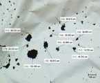
도 5는 본 발명의 실시 예에 따른 UV 검사 장치를 이용해 측정된 펠리클 멤브레인의 결함들을 나타내는 이미지이고, 도 6은 본 발명의 실시 예에 따른 EUV 검사 장치를 이용해 측정된 펠리클 멤브레인의 결함들을 나타내는 이미지이다.FIG. 5 is an image showing defects of a pellicle membrane measured using a UV inspection apparatus according to an embodiment of the present invention, and FIG. 6 is an image showing defects of a pellicle membrane measured using an EUV inspection apparatus according to an embodiment of the present invention. to be.
도 5를 참조하면, 상기 펠리클 멤브레인에 상기 UV 광을 조사하여, 상기 펠리클 멤브레인의 결함들이 검출되는 것을 확인할 수 있다. 검출된 상기 결함들은 적색 고리(red ring) 및 청색 고리(blue ring)로 도 5에 도시되었다. 본 발명의 실시 예에 따르면, 상기 UV 광원부(10)의 상기 LED 모듈에 의해, 상기 UV 광이 선형으로 상기 펠리클 멤브레인에 고속으로 조사되고, 상기 펠리클 멤브레인 상에서 산란된 UV 광이 상기 UV 검출부(30)에 의해 수집 및 측정될 수 있다. 수집 및 측정된 상기 UV 광의 발광강도는 그레이스케일로 변환되어 이미지로 획득되고, 이를 분석하여 도 5와 같이 펠리클 멤브레인의 결함들이 검출될 수 있다.Referring to FIG. 5, the pellicle membrane may be irradiated with UV light to confirm that defects of the pellicle membrane are detected. The defects detected are shown in FIG. 5 in red and blue rings. According to an embodiment of the present invention, by the LED module of the UV
도 6을 참조하면, 상기 펠리클 멤브레인에 상기 EUV 광을 조사하여, 상기 펠리클 멤브레인의 결함들이 검출되는 것을 확인할 수 있다. 검출된 상기 결함들은 적색 고리(red ring)로 도 6에 도시되었다. 본 발명의 실시 예에 따르면, 상기 EUV 광원부(40)에 의해 상기 펠리클 멤브레인에 상기 EUV 광이 조사되고, 상기 EUV 검출부(70)에 의해 상기 펠리클 멤브레인을 투과한 후 상기 다층 박막 거울(50)에 반사되어 상기 펠리클 멤브레인에 재투과된 EUV 광이 수집 및 측정될 수 있다. 수집 및 측정된 상기 EUV 광의 발광강도는 변환되어 수 나노스케일의 정밀한 이미지로 획득되고, 이를 분석하여 도 6과 같이 펠리클 멤브레인의 결함들이 검출될 수 있다.Referring to FIG. 6, it can be seen that defects of the pellicle membrane are detected by irradiating the pellicle membrane with the EUV light. The defects detected are shown in FIG. 6 with a red ring. According to an embodiment of the present invention, the EUV light is irradiated to the pellicle membrane by the EUV
본 발명의 실시 예에 따르면, 도 5에 상기 적색 고리로 도시된 상기 결함들이, 도 6에 상기 적색 고리로 도시된 결함들로 재검출 되는 경우, 본 발명의 상기 제1 타입 결함으로 분류되어 데이터베이스로 저장될 수 있다. 그러나, 도 5에 상기 청색 고리로 도시된 상기 결함들이, 도 6에 상기 적색 고리로 도시된 결함들로 재검출 되지 않는 경우, 본 발명의 상기 제2 타입 결함으로 분류되어 데이터베이스로 저장될 수 있다.According to an embodiment of the present invention, when the defects represented by the red rings in FIG. 5 are redetected as the defects shown in the red rings in FIG. Can be stored as. However, if the defects shown by the blue ring in FIG. 5 are not redetected as defects shown in the red ring in FIG. 6, they may be classified as the second type defects of the present invention and stored in a database. .
본 발명에 따르면, 상기 제1 및 제2 타입 결함으로 분류되는 펠리클 멤브레인의 검사 데이터베이스가 구축됨에 따라, 상기 데이터베이스를 이용해 EUV 광을 조사하지 않고도, UV 광을 조사하는 것만으로, 용이하게 상기 EUV 광에 의해 검출되는 결함을 예측하는 것이 가능하다.According to the present invention, as the inspection database of the pellicle membrane classified as the first and second type defects is established, the EUV light is easily irradiated by simply irradiating UV light without irradiating EUV light using the database. It is possible to predict the defects detected by.
이하, 본 발명의 실시 예에 따른 펠리클 멤브레인의 검사 방법이 설명된다.Hereinafter, a method of inspecting a pellicle membrane according to an embodiment of the present invention will be described.
도 7은 본 발명의 실시 예에 따른 데이터베이스를 이용한 펠리클 멤브레인의 검사 방법을 설명하기 위한 순서도이다.7 is a flowchart illustrating a method of inspecting a pellicle membrane using a database according to an embodiment of the present invention.
도 7을 참조하면, UV 광 및 EUV 광에 의해 검출 가능한 제1 타입 결함, 및 상기 UV 광에 의해 검출되고 상기 EUV 광에 의해 검출되지 않는 제2 타입 결함에 대한 정보를 갖는 데이터 베이스를 준비할 수 있다(S210). 상술된 바와 같이, 상기 데이터 베이스를 이용하는 경우, 상기 EUV 광을 조사하지 않고도, 상기 UV 광을 조사하는 것만으로, 용이하게 상기 EUV 광에 의해 검출되는 결함을 예측하는 것이 가능하다.Referring to FIG. 7, a database having a first type defect detectable by UV light and EUV light and a second type defect detected by the UV light and not detected by the EUV light is prepared. It may be (S210). As described above, when the database is used, it is possible to easily predict a defect detected by the EUV light only by irradiating the UV light without irradiating the EUV light.
펠리클 멤브레인을 포함하는 펠리클을 준비할 수 있다(S220). 상기 펠리클은 반도체 제조 공정에서 사용될 수 있는 펠리클이라면 어느 것이든 한정되지 않는다.A pellicle including a pellicle membrane may be prepared (S220). The pellicle is not limited to any pellicle that can be used in the semiconductor manufacturing process.
상기 펠리클 멤브레인에 상기 UV 광을 조사하여 결함을 검출할 수 있다 (S230). 상기 UV 광은, 본 발명에 따른 복수의 LED 광원 유닛이 일렬로 배치된, LED 모듈을 사용하여, 선형으로 조사되어, 상기 펠리클 멤브레인의 대면적을 고속으로 검사할 수 있다.Defects may be detected by irradiating the pellicle membrane with the UV light (S230). The UV light can be irradiated linearly using an LED module in which a plurality of LED light source units according to the present invention are arranged in a line, so that the large area of the pellicle membrane can be inspected at high speed.
상기 UV 광에 의해 검출된 결함이 상기 제1 타입 결함 또는 상기 제2 타입 결함 중에서 어느 것에 해당되는지 판단할 수 있다. 다시 말해, 상기 UV 광에 의해 검출된 결함이 상기 제1 타입 결함인지, 또는 아니지 판단할 수 있다(S240).It may be determined whether the defect detected by the UV light corresponds to the first type defect or the second type defect. In other words, it may be determined whether the defect detected by the UV light is the first type defect or not (S240).
상기 UV 광에 의해 검출된 결함이 상기 제1 타입 결함인 경우, 최종적 결함인 것으로 판단될 수 있다 (S250). 반면에, 상기 UV 광에 의해 검출된 결함이 상기 제1 타입 결함이 아닌 경우(S240), 즉, 상기 제2 타입 결함인 경우, 최종적 결함이 아닌 것으로 판단될 수 있다(S260).When the defect detected by the UV light is the first type defect, it may be determined that the defect is final (S250). On the other hand, when the defect detected by the UV light is not the first type defect (S240), that is, the second type defect, it may be determined that the final defect is not (S260).
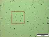
도 8 및 도 9는 본 발명의 실시 예에 따른 UV 검사 장치의 성능을 나타내는 사진이다.8 and 9 are photographs showing the performance of the UV inspection apparatus according to an embodiment of the present invention.
도 8을 참조하면, 펠리클 멤브레인을 광학 현미경(optical microscope)으로 촬영하여 나타내었고, 도 9를 참조하면, 상기 실시 예에 따른 UV 검사 장치를 이용하여 도 8의 촬영에 사용된 펠리클 멤브레인의 오염물들을 검사하여 나타내었다.Referring to FIG. 8, the pellicle membrane is photographed by an optical microscope. Referring to FIG. 9, the contaminants of the pellicle membrane used in the imaging of FIG. 8 are photographed using a UV inspection apparatus according to the embodiment. Examination was shown.
도 8 및 도 9에서 확인할 수 있듯이, 상기 실시 예에 따른 UV 검사 장치의 경우, 약 5~130 μm 크기의 오염물(particle)들을 검출할 수 있는 것을 확인할 수 있었다.As can be seen in Figures 8 and 9, in the case of the UV inspection apparatus according to the embodiment, it was confirmed that it can detect the particles (particles) of about 5 ~ 130 μm size.
도 10 및 도 11은 본 발명의 실시 예에 따른 EUV 검사 장치의 성능을 나타내는 사진이다.10 and 11 are photographs showing the performance of the EUV inspection apparatus according to an embodiment of the present invention.
도 10의 (a) 내지 (c)를 참조하면, 펠리클 멤브레인에 존재하는 서로 다른 크기의 오염물들을 광학 현미경(optical microscope)으로 촬영하여 나타내었고, 도 11을 참조하면, 상기 실시 예에 따른 EUV 검사 장치를 이용하여 도 10의 촬영에 사용된 펠리클 멤브레인의 오염물들을 검사하여 나타내었다.Referring to (a) to (c) of FIG. 10, contaminants of different sizes present in the pellicle membrane are photographed and photographed with an optical microscope. Referring to FIG. 11, EUV inspection according to the embodiment is shown. Contaminants of the pellicle membrane used for the imaging of FIG. 10 using the device were examined and shown.
도 10 및 도 11에서 확인할 수 있듯이, 상기 실시 예에 따른 EUV 검사 장치의 경우, 100 um2, 50 um2,30 um2 크기의 오염물들을 검출할 수 있는 것을 확인할 수 있었다.10 and 11, in the case of the EUV inspection apparatus according to the embodiment, it could be confirmed that contaminants having a size of 100 um2 , 50 um2, and 30 um2 can be detected.
도 12 및 도 13은 오염된 펠리클이 마스크 패턴 이미징에 미치는 효과를 나타내는 사진 및 그래프이다.12 and 13 are photographs and graphs showing the effect of contaminated pellicle on mask pattern imaging.
도 12의 (a)를 참조하면, 128nm HP(@mask) L/S 패턴 EUV 마스크를 이미징 하여 나타내었고, 도 12의 (b)를 참조하면, 도 12의 (a)에서 상술된 마스크에 10 μm 크기 이상의 particle에 의하여 오염된 펠리클을 부착한 후 이를 이미징 하여 나타내었다.Referring to (a) of FIG. 12, a 128 nm HP (@mask) L / S pattern EUV mask is imaged and shown. Referring to FIG. 12 (b), the mask described above in FIG. The pellicle contaminated with particles larger than μm was attached and imaged.
도 12의 (a)에서 확인할 수 있듯이, 펠리클이 부착되지 않은 상태의 마스크를 이미징한 경우, 패턴이 선명하게 보이는 것을 확인할 수 있었다. 반면, 도 12의 (b)에서 확인할 수 있듯이, 오염된 펠리클이 부착된 마스크를 이미징한 경우, 패턴의 형상이 뚜렷하게 나타나지 않는 것을 확인할 수 있었다.As can be seen in FIG. 12A, when the mask was imaged without the pellicle, the pattern was clearly seen. On the other hand, as shown in Figure 12 (b), when imaging the mask with contaminated pellicle, it was confirmed that the shape of the pattern does not appear clearly.
도 13의 (a)를 참조하면, 도 12의 (a)에서 상술된 마스크에 대해 magnitude profile을 분석하여 나타내었고, 도 13의 (b)를 참조하면, 도 12의 (b)에서 상술된 마스크에 대해 magnitude profile을 분석하여 나타내었다.Referring to FIG. 13A, the magnitude profile of the mask described above in FIG. 12A is analyzed and represented. Referring to FIG. 13B, the mask described above in FIG. 12B is illustrated. The magnitude profile is analyzed for.
도 13의 (a) 및 (b)에서 알 수 있듯이, 펠리클이 없는 상태의 마스크는 peak 및 valley가 명확하게 나타나지만, 펠리클이 부착된 상태의 마스크는 peak 및 valley가 불명확하게 나타내는 것을 확인할 수 있었다.As can be seen from (a) and (b) of FIG. 13, the peak and valley of the mask without the pellicle are clearly seen, but the peak and the valley of the mask with the pellicle are unclear.
도 14 및 도 15는 마스크 패턴 이미징에 영향을 미치는 펠리클 오염원의 임계 크기를 확인하는 사진이다.14 and 15 are photographs confirming the critical size of pellicle contaminants affecting mask pattern imaging.
도 14를 참조하면, 다양한 크기의 오염원이 있는 펠리클을 광학 현미경(optical microscope)으로 촬영하여 나타내었다. 도 14에서 확인할 수 있듯이, 펠리클에 1~10 μm 크기의 오염원들이 있는 것을 확인할 수 있었다.Referring to FIG. 14, pellicles having various sizes of contaminants are photographed by an optical microscope. As can be seen in Figure 14, the pellicle was confirmed that there are contaminants of 1 ~ 10 μm in size.
도 15의 (a) 및 (b)를 참조하면, 도 14에서 상술된 펠리클을 128nm HP(@mask) L/S 패턴 EUV 마스크에 부착한 후, 이를 이미징하여 나타내었다. 도 15의 (a) 및 (b)에서 확인할 수 있듯이, 마스크의 패턴들이 선명하게 나타내는 것을 확인할 수 있었다. 즉, 1~10 μm 크기의 오염원들의 경우, 마스크 이미징에 영향을 미치지 않는 다는 것을 확인할 수 있었다.Referring to FIGS. 15A and 15B, the pellicle described above in FIG. 14 is attached to a 128 nm HP (@mask) L / S pattern EUV mask and then imaged. As can be seen from (a) and (b) of FIG. 15, it was confirmed that the patterns of the mask were clearly displayed. In other words, in the case of 1-10 μm contaminants, it did not affect mask imaging.
결과적으로, UV를 이용한 검사에서는 오염원이 검출 되었으나, EUV 마스크 이미징에는 영향을 미치지 않음을 확인할 수 있었다. 이에 따라, UV를 통한 1차 검사에서 10 μm 이하 크기의 오염원이 검출되는 경우, 추가적인 EUV 검사가 필요 없이 오염물을 검출할 수 있어, 펠리클의 검사속도 및 생산성을 향상시킬 수 있다.As a result, it was confirmed that the contamination was detected in the UV test, but did not affect the EUV mask imaging. Accordingly, when a source of contamination of 10 μm or less is detected in the primary inspection through UV, the contamination can be detected without the need for additional EUV inspection, thereby improving the inspection speed and productivity of the pellicle.
이상, 본 발명을 바람직한 실시 예를 사용하여 상세히 설명하였으나, 본 발명의 범위는 특정 실시 예에 한정되는 것은 아니며, 첨부된 특허청구범위에 의하여 해석되어야 할 것이다. 또한, 이 기술분야에서 통상의 지식을 습득한 자라면, 본 발명의 범위에서 벗어나지 않으면서도 많은 수정과 변형이 가능함을 이해하여야 할 것이다.As mentioned above, although this invention was demonstrated in detail using the preferable embodiment, the scope of the present invention is not limited to a specific embodiment, Comprising: It should be interpreted by the attached Claim. In addition, those skilled in the art should understand that many modifications and variations are possible without departing from the scope of the present invention.
10: UV 광원부
20: 제1 펠리클 스테이지
21: 제1 스테이지
22: 제1 지지부
23: 제2 지지부
30: UV 검출부
40: EUV 광원부
50: 다층 박막 거울
60: 제2 펠리클 스테이지
61: 제2 스테이지
62: 제3 스테이지
63: 제3 및 제4 지지부들
64: 제5 및 제6 지지부들
70: EUV 검출부
100: 펠리클10: UV light source
20: first pellicle stage
21: first stage
22: first support
23: second support
30: UV detection unit
40: EUV light source
50: multilayer thin film mirror
60: second pellicle stage
61: second stage
62: third stage
63: third and fourth supports
64: fifth and sixth supports
70: EUV detector
100: pellicle
Claims (10)
Translated fromKorean상기 펠리클 멤브레인에 UV(ultraviolet) 광을 조사하여, 상기 펠리클 멤브레인의 결함들을 검출하는 단계;
상기 펠리클 멤브레인에 EUV(extreme ultraviolet) 광을 조사하여, 상기 펠리클 멤브레인의 결함들을 검출하는 단계; 및
상기 UV 광에 의해 검출된 결함들 중에서, 상기 EUV 광에 의해 검출된 결함은 제1 타입 결함으로 분류하고, 상기 EUV 광에 의해 검출되지 않은 결함은 제2 타입 결함으로 분류하여 저장하는 단계를 포함하는 펠리클 멤브레인의 검사 데이터베이스 구축 방법.
Preparing a pellicle comprising a pellicle membrane;
Irradiating UV light to the pellicle membrane to detect defects of the pellicle membrane;
Irradiating EUV (extreme ultraviolet) light on the pellicle membrane to detect defects in the pellicle membrane; And
Among the defects detected by the UV light, the defect detected by the EUV light is classified as a first type defect, and the defect not detected by the EUV light is classified and stored as a second type defect. How to build an inspection database of pellicle membranes.
상기 EUV 광이 상기 펠리클 멤브레인에 조사되는 면적보다, 상기 UV 광이 상기 펠리클 멤브레인에 조사되는 면적이 더 넓은 것을 포함하는 펠리클 멤브레인의 검사 데이터베이스 구축 방법.
The method of claim 1,
And an area in which the UV light is irradiated to the pellicle membrane is larger than an area in which the EUV light is irradiated to the pellicle membrane.
상기 펠리클 멤브레인에 상기 UV 광을 선형으로 조사하는 것을 포함하는 펠리클 멤브레인의 검사 데이터베이스 구축 방법.
The method of claim 1,
And irradiating the pellicle membrane linearly with the UV light.
복수의 LED(light emitting diode) 광원 유닛이 일렬로 배치된, LED 모듈에 의해 상기 UV 광이 선형으로 조사되는 것을 포함하는 펠리클 멤브레인의 검사 데이터베이스 구축 방법.
The method of claim 3, wherein
A method of constructing a test database of a pellicle membrane comprising linearly irradiating said UV light by an LED module, wherein a plurality of light emitting diode (LED) light source units are arranged in a line.
상기 EUV 광이 상기 펠리클 멤브레인에 조사되는 시간보다, 상기 UV 광이 상기 펠리클 멤브레인에 조사되는 시간이 더 짧은 것을 포함하는 펠리클 멤브레인의 검사 데이터베이스 구축 방법.
The method of claim 1,
And a shorter time for the UV light to irradiate the pellicle membrane than a time for the EUV light to irradiate the pellicle membrane.
상기 펠리클 멤브레인의 결함들은, 결함 종류, 크기 또는 위치 중 적어도 어느 하나에 따라 상기 제1 타입 결함 및 상기 제2 타입 결함으로 구별되어 데이터베이스로 저장되는 것을 포함하는 펠리클 멤브레인의 검사 데이터베이스 구축 방법.
The method of claim 1,
And the defects of the pellicle membrane are classified into the first type defect and the second type defect and stored in a database according to at least one of a defect type, a size, or a position.
상기 펠리클은 이동 가능한 스테이지 상에 배치되고, 상기 스테이지의 이동에 따라, 상기 펠리클 멤브레인의 결함이 영상으로 검출되는 것을 포함하는 펠리클 멤브레인의 검사 데이터베이스 구축 방법.
The method of claim 1,
And wherein the pellicle is disposed on a movable stage, wherein, as the stage moves, defects in the pellicle membrane are detected as an image.
펠리클 멤브레인을 포함하는 펠리클을 준비하는 단계;
상기 펠리클 멤브레인에 상기 UV 광을 조사하여 결함을 검출하는 단계; 및
상기 UV 광에 의해 검출된 결함이 상기 제1 타입 결함 또는 상기 제2 타입 결함 중에서 어느 것에 해당되는지 판단하는 단계를 포함하는 데이터베이스를 이용한 펠리클 멤브레인의 검사 방법.
Preparing a database having information about a first type defect detectable by UV light and EUV light, and a second type defect detected by the UV light and not detected by the EUV light;
Preparing a pellicle comprising a pellicle membrane;
Irradiating the pellicle membrane with the UV light to detect a defect; And
And determining whether the defect detected by the UV light corresponds to the first type defect or the second type defect.
상기 제1 타입 결함으로 분류되는 경우, 최종적 결함인 것으로 판단되는 것을 포함하는 데이터베이스를 이용한 펠리클 멤브레인의 검사 방법.
The method of claim 8,
When classified as the first type defect, the method of inspecting a pellicle membrane using a database comprising the determination that the final defect.
상기 제2 타입 결함으로 분류되는 경우, 최종적 결함이 아닌 것으로 판단되는 것을 포함하는 데이터베이스를 이용한 펠리클 멤브레인의 검사 방법.
The method of claim 8,
If it is classified as the second type defect, the inspection method of the pellicle membrane using a database comprising that it is determined that the final defect.
Applications Claiming Priority (2)
| Application Number | Priority Date | Filing Date | Title |
|---|---|---|---|
| KR1020180021282 | 2018-02-22 | ||
| KR20180021282 | 2018-02-22 |
Publications (2)
| Publication Number | Publication Date |
|---|---|
| KR20190101301Atrue KR20190101301A (en) | 2019-08-30 |
| KR102297038B1 KR102297038B1 (en) | 2021-09-03 |
Family
ID=67776525
Family Applications (1)
| Application Number | Title | Priority Date | Filing Date |
|---|---|---|---|
| KR1020190020824AActiveKR102297038B1 (en) | 2018-02-22 | 2019-02-22 | Construction method of database for pellicle membrane inspection and Method of inspecting pellicle membrane using the database |
Country Status (1)
| Country | Link |
|---|---|
| KR (1) | KR102297038B1 (en) |
Citations (5)
| Publication number | Priority date | Publication date | Assignee | Title |
|---|---|---|---|---|
| KR20070019174A (en)* | 2005-08-11 | 2007-02-15 | 삼성전자주식회사 | Semiconductor exposure equipment and pellicle inspection method |
| KR20070032225A (en)* | 2005-09-16 | 2007-03-21 | 가부시끼가이샤 도시바 | Mask defect inspection method, mask defect inspection apparatus, and manufacturing method of semiconductor device |
| JP2015204339A (en)* | 2014-04-11 | 2015-11-16 | レーザーテック株式会社 | Pellicle inspection device |
| KR20170110759A (en)* | 2016-03-23 | 2017-10-12 | 한양대학교 산학협력단 | Testing device for pellicle and method for testing using same |
| KR20170127102A (en)* | 2016-05-10 | 2017-11-21 | 한양대학교 산학협력단 | Reconstructing optimized image of EUV mask and pellicle by adding update parameter method into ptychography |
- 2019
- 2019-02-22KRKR1020190020824Apatent/KR102297038B1/enactiveActive
Patent Citations (5)
| Publication number | Priority date | Publication date | Assignee | Title |
|---|---|---|---|---|
| KR20070019174A (en)* | 2005-08-11 | 2007-02-15 | 삼성전자주식회사 | Semiconductor exposure equipment and pellicle inspection method |
| KR20070032225A (en)* | 2005-09-16 | 2007-03-21 | 가부시끼가이샤 도시바 | Mask defect inspection method, mask defect inspection apparatus, and manufacturing method of semiconductor device |
| JP2015204339A (en)* | 2014-04-11 | 2015-11-16 | レーザーテック株式会社 | Pellicle inspection device |
| KR20170110759A (en)* | 2016-03-23 | 2017-10-12 | 한양대학교 산학협력단 | Testing device for pellicle and method for testing using same |
| KR20170127102A (en)* | 2016-05-10 | 2017-11-21 | 한양대학교 산학협력단 | Reconstructing optimized image of EUV mask and pellicle by adding update parameter method into ptychography |
Also Published As
| Publication number | Publication date |
|---|---|
| KR102297038B1 (en) | 2021-09-03 |
Similar Documents
| Publication | Publication Date | Title |
|---|---|---|
| JP5355294B2 (en) | Particle detection on object surface | |
| US6184976B1 (en) | Apparatus and method for measuring an aerial image using transmitted light and reflected light | |
| TWI342038B (en) | ||
| KR101807396B1 (en) | Testing device for pellicle and method for testing using same | |
| US20150226539A1 (en) | System and method for determining the position of defects on objects, coordinate measuring unit and computer program for coordinate measuring unit | |
| TWI490963B (en) | Methods of inspecting and processing semiconductor wafers | |
| JP2008249575A (en) | Pattern defect inspection method | |
| JP2006003364A (en) | Wafer inspection method and system | |
| JP5787261B2 (en) | Inspection apparatus and inspection method | |
| US11137693B2 (en) | Pellicle holder, pellicle inspection apparatus, and pellicle inspection method | |
| KR20030096400A (en) | Arrangement and method for detecting defects on a substrate in a processing tool | |
| US9355919B2 (en) | Methods and systems for inspecting bonded wafers | |
| US20250314958A1 (en) | Contaminant identification metrology system, lithographic apparatus, and methods thereof | |
| US8049897B2 (en) | Reticle defect inspection apparatus and inspection method using thereof | |
| TWI887539B (en) | Defect inspection device, defect inspection method and blank mask manufacturing method | |
| US7243331B2 (en) | Method and system for controlling the quality of a reticle | |
| KR20200066540A (en) | Pellicle holder, Pellicle Inspection system, and Pellicle Inspection method | |
| KR102297038B1 (en) | Construction method of database for pellicle membrane inspection and Method of inspecting pellicle membrane using the database | |
| CN114641726B (en) | Integrated multi-tool photomask inspection | |
| JP2008140795A (en) | Exposure apparatus and method, and device manufacturing method | |
| JP4883817B2 (en) | Inspection apparatus, inspection method, and pattern substrate manufacturing method | |
| KR20090072808A (en) | Inspection apparatus of photomask and inspection method using the same | |
| KR20230144220A (en) | Comprehensive inspection equipment for EUV exposure process | |
| JP4521548B2 (en) | Inspection apparatus, inspection method, and pattern substrate manufacturing method | |
| WO2006019446A2 (en) | Double inspection of reticle or wafer |
Legal Events
| Date | Code | Title | Description |
|---|---|---|---|
| A201 | Request for examination | ||
| PA0109 | Patent application | Patent event code:PA01091R01D Comment text:Patent Application Patent event date:20190222 | |
| PA0201 | Request for examination | ||
| PG1501 | Laying open of application | ||
| E902 | Notification of reason for refusal | ||
| PE0902 | Notice of grounds for rejection | Comment text:Notification of reason for refusal Patent event date:20201106 Patent event code:PE09021S01D | |
| E701 | Decision to grant or registration of patent right | ||
| PE0701 | Decision of registration | Patent event code:PE07011S01D Comment text:Decision to Grant Registration Patent event date:20210602 | |
| PR0701 | Registration of establishment | Comment text:Registration of Establishment Patent event date:20210827 Patent event code:PR07011E01D | |
| PR1002 | Payment of registration fee | Payment date:20210827 End annual number:3 Start annual number:1 | |
| PG1601 | Publication of registration | ||
| PR1001 | Payment of annual fee | Payment date:20240701 Start annual number:4 End annual number:4 |