KR20190091244A - Femoral arterial Cannula capable of guidance of bidirectional flow - Google Patents
Femoral arterial Cannula capable of guidance of bidirectional flowDownload PDFInfo
- Publication number
- KR20190091244A KR20190091244AKR1020190091242AKR20190091242AKR20190091244AKR 20190091244 AKR20190091244 AKR 20190091244AKR 1020190091242 AKR1020190091242 AKR 1020190091242AKR 20190091242 AKR20190091242 AKR 20190091242AKR 20190091244 AKR20190091244 AKR 20190091244A
- Authority
- KR
- South Korea
- Prior art keywords
- cannula
- blood flow
- femoral artery
- cannula tube
- blood
- Prior art date
- Legal status (The legal status is an assumption and is not a legal conclusion. Google has not performed a legal analysis and makes no representation as to the accuracy of the status listed.)
- Granted
Links
Images


Classifications
- A—HUMAN NECESSITIES
- A61—MEDICAL OR VETERINARY SCIENCE; HYGIENE
- A61M—DEVICES FOR INTRODUCING MEDIA INTO, OR ONTO, THE BODY; DEVICES FOR TRANSDUCING BODY MEDIA OR FOR TAKING MEDIA FROM THE BODY; DEVICES FOR PRODUCING OR ENDING SLEEP OR STUPOR
- A61M25/00—Catheters; Hollow probes
- A61M25/0067—Catheters; Hollow probes characterised by the distal end, e.g. tips
- A61M25/0068—Static characteristics of the catheter tip, e.g. shape, atraumatic tip, curved tip or tip structure
- A61M25/007—Side holes, e.g. their profiles or arrangements; Provisions to keep side holes unblocked
- A—HUMAN NECESSITIES
- A61—MEDICAL OR VETERINARY SCIENCE; HYGIENE
- A61M—DEVICES FOR INTRODUCING MEDIA INTO, OR ONTO, THE BODY; DEVICES FOR TRANSDUCING BODY MEDIA OR FOR TAKING MEDIA FROM THE BODY; DEVICES FOR PRODUCING OR ENDING SLEEP OR STUPOR
- A61M25/00—Catheters; Hollow probes
- A61M25/0043—Catheters; Hollow probes characterised by structural features
Landscapes
- Health & Medical Sciences (AREA)
- Life Sciences & Earth Sciences (AREA)
- Biophysics (AREA)
- Pulmonology (AREA)
- Engineering & Computer Science (AREA)
- Anesthesiology (AREA)
- Biomedical Technology (AREA)
- Heart & Thoracic Surgery (AREA)
- Hematology (AREA)
- Animal Behavior & Ethology (AREA)
- General Health & Medical Sciences (AREA)
- Public Health (AREA)
- Veterinary Medicine (AREA)
- Media Introduction/Drainage Providing Device (AREA)
Abstract
Description
Translated fromKorean본 발명은 대퇴동맥 캐뉼러 삽입 방향 및 삽입 반대 방향 혈류를 위한 캐뉼러에 관한 것으로서, 상세히는 대퇴동맥에 삽입되는 캐뉼러의 캐뉼러 관 끝단 안쪽의 둘레 면에 혈류 유도로 또는 이 혈류 유도로와 함께 관통홀을 형성하거나, 상기 관통홀보다 더 큰 관통홀 및 이 관통홀 상부를 덮는 유도 커버를 함께 형성함으로써 상기 혈류 유도로나 혈류 유도로와 관통홀 또는 상기 관통홀과 유도 커버를 통해 대퇴동맥에서 혈류가 하지 말단 방향으로도 흐를 수 있도록 한 양방향 혈류 유도가 가능한 대퇴동맥 캐뉼러에 관한 것이다.The present invention relates to a cannula for blood flow in the direction of the femoral artery cannula insertion and in the opposite direction of the artery. In the femoral artery through the blood flow guide or blood flow guide passage and the through hole or the through hole and the guide cover by forming a through hole together or forming a through hole larger than the through hole and an induction cover covering the upper portion of the through hole. The present invention relates to a femoral artery cannula capable of inducing bidirectional blood flow so that blood flows in the lower extremity.
환자의 심장 수술, 혹은 심장 부전의 상태에서 심장 보조 요법으로 체외순환을 이용하게 되는데, 산소화된 혈액을 공급하기 위해 대퇴동맥 삽관법(Femoral arterial cannulation)을 흔히 사용하고 있다. 이러한 상기 대퇴동맥 삽관법은 외과적으로 혈관을 노출시켜서 시행하기도 하나, 많은 경우 피부를 통해 가이드 와이어를 삽입하는 경피적 방법 (Seldingers technique)를 이용한다. 이때 상기 캐뉼러는 서혜부 부근의 대퇴동맥에 삽입되기 때문에 가장 문제가 되는 것은 다리 말단의 혈류(distal limb perfusion)이다. 이는 허벅지 윗부분의 환자의 상체 부분으로는 상기 대퇴동맥 삽관법에 의해 혈액이 공급되지만, 굵은 캐뉼러에 의해 말단 방향의 혈류가 감소 혹은 차단되게 된다. 따라서 허벅지 아랫부분의 다리에서부터 먼 말단의 발까지 대퇴동맥 캐뉼러를 유지하는 시간 동안 혈액이 공급되지 않아 다리가 괴사할 우려가 있을 수 있다.Extracorporeal circulation is used as a cardiac adjuvant therapy in patients with heart surgery or heart failure. Femoral arterial cannulation is commonly used to supply oxygenated blood. The femoral artery intubation may be performed by exposing the blood vessels surgically, but in many cases, a percutaneous method (Seldingers technique) is used to insert a guide wire through the skin. At this time, the cannula is inserted into the femoral artery near the groin, so the most problematic problem is the distal limb perfusion. The blood is supplied to the upper part of the patient's upper thigh by the femoral artery intubation, but the blood flow in the distal direction is reduced or blocked by the thick cannula. Therefore, blood may not be supplied during the time of maintaining the femoral artery cannula from the lower leg of the thigh to the far end of the foot, which may cause necrosis of the leg.
이 때문에 종래에는 이러한 일을 발생하지 않도록 다리 쪽으로도 혈액을 공급하는 separate antegrade catheterization 또는 posterior tibial artery cannulation 등 다양한 기술이 사용되지만, 모두 합병증이나 혈관 끊어짐의 현상이 발생하여 이러한 기술들을 적용하는 데에 기술적 어려움을 동반하고 있다.For this reason, conventional techniques such as separate antegrade catheterization or posterior tibial artery cannulation, which supply blood to the legs to prevent this from happening, are all used. It is accompanied by difficulties.
본 발명은 상기한 바와 같은 제반 문제점을 개선하기 위해 안출된 것으로서, 그 목적은 대퇴동맥 캐뉼러의 끝단에 혈류 유도로 또는 상기 혈류 유도로와 함께 관통홀을 형성하여, 수술중 심장이나 폐에 혈액을 공급하면서 상기 심장이나 폐에 공급되는 혈류의 일부가 상기 혈류 유도로 또는 관통홀과 혈류 유도로를 통해 역행하여 반대쪽의 다리 말단에도 혈액이 공급될 수 있도록 한 양방향 혈류 유도가 가능한 대퇴동맥 캐뉼러를 제공함에 있다.The present invention has been made to improve the above-described problems, the object of which is to form a through-hole with the blood flow guide or the blood flow guide in the end of the femoral artery cannula, blood in the heart or lung during surgery Part of the blood flow supplied to the heart or lung while supplying the back is reversed through the blood flow guide or through-hole and blood flow guide to allow blood to be supplied to the opposite leg end. In providing.
다른 목적은 대퇴동맥 캐뉼러의 끝단에 관통홀과 함께 상기 관통홀을 덮어 돌출되는 유도 커버를 각각 형성하여, 체외순환 혈류의 일부가 상기 관통홀과 유도 커버를 통해 역행하여 반대쪽의 다리 말단에도 혈액이 공급될 수 있도록 한 양방향 혈류 유도가 가능한 대퇴동맥 캐뉼러를 제공함에 있다.Another purpose is to form an induction cover that protrudes by covering the through hole with the through hole at the end of the femoral artery cannula, so that a part of the extracorporeal blood flow backs through the through hole and the induction cover, and the blood at the opposite leg end The present invention provides a femoral artery cannula capable of inducing bidirectional blood flow.
상기한 바와 같은 목적을 달성하기 위해 본 발명의 양방향 혈류 유도가 가능한 대퇴동맥 캐뉼러는, 대퇴동맥의 혈관에 삽입되는 캐뉼러 관을 갖는 캐뉼러에 있어서, 상기 캐뉼러 관 끝단 안쪽의 둘레 면 소정부위에서부터 길이방향을 따라 반대편 끝단까지 오목부로 형성되는 혈류 유도로를 포함한 것을 특징으로 하고 있다.In order to achieve the object as described above, the bidirectional blood flow-induced femoral artery cannula of the present invention is a cannula having a cannula tube inserted into a blood vessel of the femoral artery. It characterized in that it comprises a blood flow induction path formed by a recess from the site to the opposite end along the longitudinal direction.
또 상기 캐뉼러 관 끝단 방향에서 혈류 유도로와 캐뉼러 관 사이의 경계 부위에 형성한 관통홀을 더 포함하는 것이 바람직하다.In addition, it is preferable to further include a through-hole formed in the boundary between the blood flow guide passage and the cannula tube in the cannula tube end direction.
또 상기 관통홀의 상단에서 혈류 유도로의 방향으로 돌출하여 연장되는 유도 외벽을 형성하는 것이 바람직하다.In addition, it is preferable to form an induction outer wall which protrudes from the upper end of the through hole in the direction of the blood flow induction path.
또 상기 캐뉼러 관은 5∼8㎜의 내경을 갖는 캐뉼러이며, 상기 관통홀은 2∼3㎜의 내경으로 형성되는 것이 바람직하다.The cannula tube is preferably a cannula having an inner diameter of 5 to 8 mm, and the through hole is formed to have an inner diameter of 2 to 3 mm.
또 상기 혈류 유도로는 고랑 형태의 라운드형인 것이 바람직하다.In addition, the blood flow induction is preferably in the form of round grooves.
또 대퇴동맥의 혈관에 삽입되는 캐뉼러 관을 갖는 캐뉼러에 있어서, 상기 캐뉼러 관 끝단 안쪽의 둘레 면 소정부위에 관통홀이 형성되고, 상기 관통홀 상부를 덮어 혈류를 안내하는 유도 커버가 관통홀 상부에 형성된 것을 다른 특징으로 하고 있다.In the cannula having a cannula tube inserted into a blood vessel of the femoral artery, a through hole is formed in a predetermined portion of the periphery of the inner end of the cannula tube end, and an induction cover for covering the upper part of the through hole to guide blood flow is penetrated. What is formed in the upper part of a hole is another feature.
또 상기 유도 커버는 캐뉼러 관 끝단을 향해 비스듬히 기울여 형성하는 것이 바람직하다.In addition, the induction cover is preferably formed to be inclined at an angle toward the end of the cannula tube.
또 상기 유도 커버의 끝단 일부를 안쪽으로 구부려 형성하는 것이 바람직하다.In addition, it is preferable to be formed by bending a portion of the end of the induction cover inward.
또 대퇴동맥의 바깥쪽에 위치하는 상기 캐뉼러 관 둘레면에 상기 혈류 유도로가 위치한 부위 또는 상기 유도 커버가 위치한 부위를 구별할 수 있는 표시를 하도록 하는 것이 바람직하다.In addition, the cannula tube located on the outer side of the femoral artery is located on the circumferential surface of the blood flow guide is located or the location where the guide cover is located to distinguish it is preferable to make a mark.
본 발명의 양방향 혈류 유도가 가능한 대퇴동맥 캐뉼러에 의하면, 대퇴동맥 캐뉼러 유지 중 다리 말단으로 향하는 혈류가 이루어져 안정적으로 혈액을 공급할 수 있으므로 다리 말단의 허혈의 유병율을 현저히 줄일 수 있는 효과가 있다. 이에 따라 다리 말단 혈류를 위해 사용되는 종래 기술들을 대체하여 합병증이나 혈관 끊어짐과 같은 기술적 어려움 없이 안정적으로 대퇴동맥 삽관법을 실시할 수 있는 효과가 있다.According to the femoral artery cannula capable of inducing bidirectional blood flow of the present invention, since the blood flow is made to the end of the leg while maintaining the femoral artery cannula, blood can be stably supplied, thereby reducing the prevalence of ischemia at the end of the leg. Accordingly, there is an effect that the femoral artery intubation can be stably performed without technical difficulties such as complications or blood vessel breakdown by replacing the conventional techniques used for blood flow to the end of the leg.
또한 캐뉼러에 돌출 형성된 유도 커버가 위치하는 둘레 면 부위가 혈관 밖에 일정한 표식으로 표시되어 있어 상기 캐뉼러를 혈관의 손상을 최소화하면서 인출할 수 있는 효과가 있다.In addition, the circumferential surface portion in which the induction cover protruding from the cannula is positioned is marked with a constant mark outside the blood vessel, so that the cannula can be drawn out with minimal damage to the blood vessel.
도 1은 본 발명의 일 실시예에 따른 양방향 혈류 유도가 가능한 대퇴동맥 캐뉼러의 끝단부 사시도
도 2는 상기 도 1의 캐뉼러를 대퇴동맥에 삽입하였을 때의 종단면도
도 3은 상기 도 1의 캐뉼러를 대퇴동맥에 삽입하였을 때의 횡단면도
도 4는 본 발명의 다른 실시예에 따른 양방향 혈류 유도가 가능한 대퇴동맥 캐뉼러의 끝단부 사시도
도 5는 상기 도 4의 캐뉼러를 대퇴동맥에 삽입하였을 때의 종단면도1 is a perspective view of the distal end of the femoral artery cannula capable of inducing bidirectional blood flow according to an embodiment of the present invention
Figure 2 is a longitudinal cross-sectional view of the cannula of Figure 1 when inserted into the femoral artery
3 is a cross-sectional view when the cannula of FIG. 1 is inserted into the femoral artery.
Figure 4 is a perspective view of the end of the femoral artery cannula capable of inducing bidirectional blood flow in accordance with another embodiment of the present invention
Figure 5 is a longitudinal cross-sectional view of the cannula of Figure 4 when inserted into the femoral artery
이하, 본 발명에 따른 양방향 혈류 유도가 가능한 대퇴동맥 캐뉼러의 바람직한 실시예를 첨부한 도면을 참조로 하여 상세히 설명한다. 본 발명은 이하에서 개시되는 실시예에 한정되는 것이 아니라 서로 다른 다양한 형태로 구현될 수 있으며, 단지 본 실시예는 본 발명의 개시가 완전하도록 하며 통상의 지식을 가진 자에게 발명의 범주를 완전하게 알려주기 위하여 제공되는 것이다.Hereinafter, with reference to the accompanying drawings a preferred embodiment of the femoral artery cannula capable of inducing bidirectional blood flow according to the present invention will be described in detail. The present invention is not limited to the embodiments disclosed below, but can be implemented in various different forms, only this embodiment to make the disclosure of the present invention complete and to those skilled in the art to fully understand the scope of the invention It is provided to inform you.
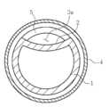
도 1은 본 발명의 일 실시예에 따른 양방향 혈류 유도가 가능한 대퇴동맥 캐뉼러의 끝단부 사시도이고, 도 2는 상기 도 1의 캐뉼러를 대퇴동맥에 삽입하였을 때의 종단면도이며, 도 3은 상기 도 1의 캐뉼러를 대퇴동맥에 삽입하였을 때의 횡단면도를 도시한 것이다.1 is a perspective view of the distal end of the femoral artery cannula capable of inducing bidirectional blood flow according to an embodiment of the present invention, Figure 2 is a longitudinal cross-sectional view when the cannula of Figure 1 is inserted into the femoral artery, Figure 3 is Figure 1 shows a cross-sectional view of the cannula when inserted into the femoral artery.
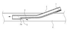
도 1 내지 도 3에 도시한 바와 같이, 본 발명의 일 실시예에 따른 양방향 혈류 유도가 가능한 대퇴동맥 캐뉼러는 대퇴동맥 삽관법(Femoral arterial cannulation)에 사용되는 상기 캐뉼러의 유연성이 있는 재료로 만들어진 캐뉼러 관(1) 끝단의 안쪽에 혈류 유도로(2)와 관통홀(3a)을 각각 형성한 것이다.1 to 3, the bidirectional blood flow-induced femoral artery cannula according to an embodiment of the present invention is a flexible material of the cannula used for femoral arterial cannulation. Cannula tube (1) end of the blood flow induction path (2) and the through hole (3a) is formed respectively.
상기 혈류 유도로(2)는 캐뉼러 관(1) 끝단의 안쪽 둘레면에서부터 길이방향을 따라 반대편 끝단까지 이어지는 라운드형의 오목부, 즉 고랑 형태로 형성한 것으로, 도 3의 횡단면도를 보면 원 둘레의 일부분을 안쪽으로 눌러 꺼져 있는 형태로 되어 있다. 이러한 혈류 유도로(2)만 가지고 본 발명의 캐뉼러를 구성할 수도 있는데, 도 2 및 도 3을 참조하면 혈관(4)에 삽입되는 본 발명의 캐뉼러의 캐뉼러 관(1)의 끝단에서 앞쪽으로 진행하는 혈류의 일부가 상기 혈류 유도로(2)에 의해 역행할 수 있도록 되어 있다. 즉 혈관(4)의 내벽과 혈류 유도로(2) 사이에 상기 혈류 유도로(2)가 없을 때보다 더 큰 간격을 형성함으로써, 상기 큰 간격을 통해 캐뉼러 관(1)의 끝단에서 앞쪽으로 진행하던 혈류의 일부가 상기 혈류 유도로(2)를 타고 역행하여 진행할 수 있게 된다(화살표 방향).The blood flow guide path (2) is formed in the shape of a round recess, that is, a furrow, extending from the inner circumferential surface of the end of the
이러한 혈류 유도로(2)는 캐뉼러 관(1) 끝단 안쪽의 둘레면 일부를 안쪽으로 눌러 형성한 것이므로 서로 크고 작은 내경, 예를 들어 larger diameter lumen과 smaller diameter lumen을 형성하게 되어, 상기 캐뉼러 관(1)의 끝단 방향에서 혈류 유도로(2)와 캐뉼러 관(1) 사이의 경계부위에 수직단차를 형성하게 되고, 상기 관통홀(3a)은 이러한 수직 단차의 수직면에 형성한 것이다. 따라서 혈류 유도로(2)에 의한 작은 내경(smaller diameter lumen)의 캐뉼러 관(1) 내부에서 끝단의 큰 내경(larger diameter lumen)의 캐뉼러 관(1) 쪽, 즉 캐뉼러 관(1)의 안쪽에서부터 상기 캐뉼러 관(1)의 끝단을 빠져나와 심장이나 폐 쪽으로 진행하는 혈류의 일부가 상기 관통홀(3a) 부위에서 U턴하여 빠져나가게 된다. 이와 동시에 관통홀(3a)을 통해 빠져나온 혈류의 일부는 혈류 유도로(2)를 타고 역행하여 진행함으로써 하지(下肢) 말단, 즉 다리 말단에도 혈액을 공급하게 된다(화살표 방향).The blood flow guide (2) is formed by pressing a part of the circumference of the inner end of the cannula tube (1) inward to form a large and small inner diameter, for example, larger diameter lumen and smaller diameter lumen, the cannula A vertical step is formed at the boundary between the blood
한편, 도 2에 도시한 바와 같이, 상기 관통홀(3a) 상단의 캐뉼러 관(1) 일부가 혈류 유도로(2) 방향으로 돌출하면서 연장되어 유도 외벽(5)을 형성할 수도 있다. 이러한 유도 외벽(5)은 관통홀(3a)을 빠져나온 혈류의 일부가 상기 유도 외벽(5)을 타고 혈류 유도로(2) 쪽으로 안정적으로 진행할 수 있도록 안내하는 일종의 안내 벽의 역할을 하게 된다. 따라서 상기한 수직단차는 관통홀(3a)을 포함한 유도 외벽(5)이라 할 수 있다.On the other hand, as shown in Figure 2, a portion of the cannula tube (1) of the upper end of the through-hole (3a) may extend while protruding in the direction of the blood flow guide (2) to form the guide outer wall (5). The induction
이러한 관통홀(3a)은 보통 5∼8㎜ 정도의 내경을 갖는 캐뉼러에서 2∼3㎜ 정도의 내경을 갖는 것이 혈류의 안정적인 역행을 위해 바람직하다.It is preferable that the
이와 같은 상기 캐뉼러 관(1)을 혈관 삽입부를 통해 혈관(4) 내로 삽입할 때에는 상기 혈류 유도로(2)에 의해 형성된 수직단차가 혈관 삽입부의 아래쪽에 위치하므로 문제가 없다. 그러나 상기 캐뉼러 관(1)을 인출하고자 할 때에는 상기 수직단차가 혈관 삽입부의 혈관 벽에 걸려 잘 인출되지 않을 수 있으므로, 상기 수직단차가 혈관 삽입부 쪽에 위치하여 이를 통해 인출될 수 있도록 상기 캐뉼러 관(1)을 회전시키는 것이 필요하다. 이를 위해서 혈관(4)의 바깥쪽에 위치하는 캐뉼러 관(1)의 둘레면 소정 부위에 수직단차와 함께 상기 혈류 유도로(2)가 위치하는 부위를 표시해주도록 한다. 이러한 표시는 혈류 유도로(2)가 위치하는 부위와 반대편의 둘레면 위치에 캐뉼러 관(1)의 색과 대비되는 서로 다른 색깔이나 특정 모양의 표시를 각각 하거나, 상기 혈류 유도로(2)가 위치하는 부위의 둘레면에만 캐뉼러 관(1)의 색과 대비되는 색깔이나 특정 모양의 표시(7)를 할 수도 있다.When the
도 4는 본 발명의 다른 실시예에 따른 대퇴동맥 하지 말단 방향을 포함한 양방향 혈류를 위한 캐뉼러의 끝단부 사시도이고, 도 5는 상기 도 4의 캐뉼러를 대퇴동맥에 삽입하였을 때의 종단면도를 도시한 것이다.Figure 4 is a perspective view of the distal end of the cannula for bidirectional blood flow including the distal end of the femoral artery according to another embodiment of the present invention, Figure 5 is a longitudinal cross-sectional view when the cannula of Figure 4 is inserted into the femoral artery It is shown.
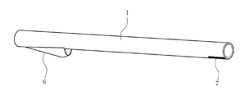
도 4 및 도 5에 도시한 바와 같이, 본 발명의 다른 실시예에 따른 대퇴동맥 하지 말단 방향을 포함한 양방향 혈류를 위한 캐뉼러는 대퇴동맥 삽관법(Femoral arterial cannulation)에 사용되는 유연성이 있는 재료로 만들어진 상기 캐뉼러의 캐뉼러 관(1) 끝단 안쪽에 관통홀(3b)과 유도 커버(6)를 각각 형성한 것이다.As shown in Figure 4 and 5, the cannula for bidirectional blood flow including the distal end of the femoral artery according to another embodiment of the present invention is a flexible material used for femoral arterial cannulation (Femoral arterial cannulation) The through-
상기 관통홀(3b)은 캐뉼러 관(1) 끝단 안쪽의 둘레 면 일부에 상기한 일 실시예의 캐뉼러의 관통홀(3a)보다 크게 형성되며, 상기 캐뉼러 관(1) 끝단의 반대 방향을 향해 비스듬히 형성하는 것이 혈류의 안정적인 역행을 위해 바람직하다.The through hole (3b) is formed in a portion of the peripheral surface inside the end of the cannula tube (1) larger than the through hole (3a) of the cannula of the embodiment described above, the opposite direction of the end of the cannula tube (1) Forming obliquely toward is preferred for stable backing of the blood flow.
상기 유도 커버(6)는 상기 관통홀(3b)에서 상부로 일정거리를 두고 비스듬히 덮도록 돌출 형성한 것으로, 캐뉼러 관(1)의 끝단 쪽을 향해 기울어져 형성됨으로써 반대편 쪽은 개방된 형태로 구성되어 있다.The
이와 같이 상기 유도 커버(6)를 비스듬히 기울여 형성함으로써 혈관 삽입부를 통해 혈관(4) 내로 캐뉼러 관(1)을 삽입할 때 무리 없이 삽입될 수 있게 된다. 다만 캐뉼러 관(1)을 혈관(4) 내에 삽입하여 사용할 때에 유도 커버(6)는 혈관 삽입부의 아래쪽에 위치하므로, 상기한 일 실시예에서의 캐뉼러에서와 같이 상기 유도 커버(6)가 혈관 삽입부 쪽에 위치하여 이를 통해 인출될 수 있도록 캐뉼러 관(1)을 회전시키는 것이 필요하다. 이를 위해서 여기에서도 혈관(4)의 바깥쪽에 위치하는 캐뉼러 관(1)의 둘레면 소정 부위에 상기 유도 커버(6)가 위치하는 부위를 표시해주도록 한다. 이러한 표시는 유도 커버(6)가 위치하는 부위와 반대편의 둘레면 위치에 캐뉼러 관(1)의 색과 대비되는 서로 다른 색깔이나 특정 모양의 표시를 각각 하거나, 상기 유도 커버(6)가 위치하는 부위의 둘레면에만 캐뉼러 관(1)의 색과 대비되는 색깔이나 특정 모양의 표시(7)를 할 수도 있다.As described above, the
한편 상기한 바와 같이 캐뉼러 관(1)을 유도 커버(6)와 함께 혈관 삽입부를통해 혈관 밖으로 인출할 때, 도 4 및 도 5에 도시한 바와 같이, 상기 유도 커버(6)의 끝단 부위를 안쪽으로 약간 구부리는 것이 안전한 인출을 위해 바람직하다. 즉 유도 커버(6)의 끝단을 안쪽으로 약간 구부리면 캐뉼러 관(1)을 인출할 때 상기 유도 커버(6)가 혈관에 걸려 인출을 어렵게 하는 문제를 간단하게 해결할 수 있다.Meanwhile, when the
이러한 관통홀(3b)과 유도 커버(6)에 의해 상기한 일 실시예의 혈류 유도로(2)와 관통홀(3a)에서와 같이 캐뉼러 관(1)을 혈관(4)에 삽입하여 혈액을 공급하면, 캐뉼러 관(1)의 안쪽에서부터 상기 캐뉼러 관(1)의 끝단을 빠져나와 심장이나 폐 쪽으로 진행하는 혈류의 일부가 상기 관통홀(3b) 부위에서 U턴하여 빠져나가게 된다. 이와 동시에 관통홀(3b)을 통해 빠져나온 혈류의 일부는 유도 커버(6)에 의해 안내되면서 역행하여 진행함으로써 말단의 다리에도 혈액을 공급하게 된다(화살표 방향).By the through
상기 캐뉼러(1)의 재료에 있어서는 환자의 신체 내부로 삽입하기에 적절한 재료로 구성될 수 있는데, 예를 들면, 세라막, 금속, 폴리머 등이 사용될 수 있으나, 환자의 체내에 장기가 있을 수 있고 생체호환적(biocompatible) 동시에 환자의 체내에 주입된 후 부드럽게 할 수 있도록 유연성이 있는 플라스틱 재료인 폴리머 종류가 적합할 수 있다. 상기 폴리머 재료는 예를 들어, 실리콘, 폴리카보네이트, 실리콘이 섞인 우레탄, 폴리스티렌-폴리이소부틸렌-폴리스티렌(SIBS)과 같은 것들을 사용할 수 있다.The material of the
또한 상기 캐뉼러(1)의 내외 표면은 측벽을 통해 혈류가 유동하는 것을 방지하고 혈전 응고 등을 고려하여 가요성 외피를 입히는 코팅을 하는 것이 바람직한데, 이러한 가요성 외피는 예를 들어 탄성중합체 외피와 같은 다양한 재료로 만들어질 수 있다. 또한 상기 코팅은 보통 중합체(폴리머) 용액 내에 침지하여 수행하게 되는데, 사용될 수 있는 중합체에는, 비제한적인 예로서, 생체적합성 중합체, 예를 들어 폴리비닐 클로라이드, 폴리올레핀(예를 들어, 폴리에틸렌, 폴리프로필렌, 에틸렌-비닐아세테이트 공중합체), 폴리아미드, 폴리에스테르(예를 들어, 폴리에틸렌 테레프탈레이트(PET), 폴리부틸렌 테레프탈레이트), 폴리우레탄, 폴리스티렌 수지, 불소계 수지(예를 들어, 폴리테트라플루오로에틸렌, 에틸렌-테트라플루오로에틸렌 공중합체), 폴리이미드 등; 및 다양한 탄성중합체, 예를 들어 폴리우레탄계 탄성중합체, 폴리에스테르계 탄성중합체, 폴리올레핀계 탄성중합체, 폴리아미드계 탄성중합체, 실리콘 고무, 라텍스 고무 및 이들의 조합이 포함된다.In addition, the inner and outer surfaces of the
상기한 캐뉼러의 재료 또는 코팅은 세포 또는 플라그가 그 위에 성장하거나 부착되는 것을 방지할 수 있다.The material or coating of the cannula can prevent cells or plaques from growing or adhering thereon.
이상과 같이 본 발명에 따른 양방향 혈류 유도가 가능한 대퇴동맥 캐뉼러에 대해서 예시한 도면을 참조로 하여 설명하였으나, 본 명세서에 개시된 실시예와 도면에 의해 본 발명이 한정되는 것은 아니며, 본 발명의 기술사상의 범위 내에서 당업자에 의해 다양한 변형이 이루어질 수 있음은 물론이다.As described above with reference to the drawings illustrated for the femoral artery cannula capable of inducing bidirectional blood flow according to the present invention, the present invention is not limited by the embodiments and drawings disclosed herein, the present invention Of course, various modifications may be made by those skilled in the art within the scope of the idea.
1 : 캐뉼러 관2 : 혈류 유도로
3a,3b : 관통홀4 : 혈관
5 : 유도 외벽6 : 유도 커버
7 : 혈류 유도로 또는 유도 커버의 위치를 나타내는 표시1: cannula tube 2: blood flow induction furnace
3a, 3b: through hole 4: blood vessel
5: induction outer wall 6: induction cover
7: Indication indicating the location of the blood flow induction furnace or induction cover
Claims (5)
Translated fromKorean상기 캐뉼러 관의 끝단 안쪽의 둘레 면 소정부위에서부터 길이방향을 따라 반대편 끝단까지, 상기 캐뉼러 관의 끝단 안쪽의 둘레면 일부를 안쪽으로 눌러진 오목부로 형성되어, 혈류가 상기 반대편 끝단까지 형성된 상기 오목부를 타고 역행하여 진행할 수 있게 하는 혈류 유도로를 포함하고,
상기 캐뉼러 관의 끝단 방향에서 상기 혈류 유도로와 상기 캐뉼러 관 사이의 경계 부위에 수직 단차가 형성되고,
상기 수직 단차의 수직면에 형성한 관통홀을 포함하고,
상기 관통홀의 상단에서 상기 캐뉼러 관의 일부가 상기 혈류 유도로의 길이방향으로 연장되어 형성된 유도 외벽을 포함하고,
상기 캐뉼러와 상기 혈류 유도로와 상기 유도 외벽의 길이방향은 서로 평행하게 형성되고,
상기 유도 외벽은 상기 관통홀을 타고 빠져나온 혈류의 일부가 상기 유도 외벽을 타고 상기 혈류 유도로 쪽으로 안정적으로 진행할 수 있도록 안내하고,
상기 소정부위에서부터 상기 반대편 끝단까지 상기 혈류 유도로와 혈관의 내벽 사이의 간격은, 상기 캐뉼러 관의 끝단과 상기 혈관의 내벽 사이의 간격보다 더 큰 것을 특징으로 하는 양방향 혈류 유도가 가능한 대퇴동맥 캐뉼러.A cannula having a cannula tube inserted into a blood vessel of the femoral artery,
The circumferential surface of the inner end of the cannula tube from the predetermined end portion in the longitudinal direction to the opposite end in the longitudinal direction, the inner part of the end of the cannula tube is formed into a recess pressed inward, the blood flow is formed to the opposite end Includes a blood flow induction path allowing the vehicle to proceed backward in the recess,
A vertical step is formed at the boundary between the blood flow guide passage and the cannula tube in an end direction of the cannula tube,
It includes a through hole formed in the vertical surface of the vertical step,
A portion of the cannula tube at an upper end of the through hole includes a guide outer wall formed to extend in the longitudinal direction of the blood flow guide passage,
The cannula and the blood flow guide passage and the longitudinal direction of the guide outer wall is formed parallel to each other,
The guided outer wall guides a part of the blood flow exiting the through hole to stably move toward the blood flow guided path through the guided outer wall,
The distance between the blood flow guide passage and the inner wall of the blood vessel from the predetermined portion to the opposite end is greater than the distance between the end of the cannula tube and the inner wall of the blood vessel. Cannula.
상기 캐뉼러 관은 5∼8㎜의 내경을 갖는 캐뉼러인 것을 특징으로 하는 양방향 혈류 유도가 가능한 대퇴동맥 캐뉼러.The method of claim 1,
The cannula tube is bidirectional blood flow guide femoral artery cannula, characterized in that the cannula having an inner diameter of 5 ~ 8mm.
상기 관통홀은 2∼3㎜의 내경으로 형성되는 것을 특징으로 하는 양방향 혈류 유도가 가능한 대퇴동맥 캐뉼러.The method of claim 2,
The through-hole is femoral artery cannula capable of inducing bi-directional blood flow, characterized in that formed with an inner diameter of 2-3mm.
상기 혈류 유도로는 고랑 형태의 라운드형인 것을 특징으로 하는 양방향 혈류 유도가 가능한 대퇴동맥 캐뉼러.The method of claim 1,
The blood flow induction path is femoral artery cannula capable of inducing bidirectional blood flow, characterized in that the round-shaped furrow.
대퇴동맥의 바깥쪽에 위치하는 상기 캐뉼러 관의 둘레면에 상기 혈류 유도로가 위치한 부위 또는 상기 유도 외벽이 위치한 부위를 구별할 수 있는 표시를 하도록 한 것을 특징으로 하는 양방향 혈류 유도가 가능한 대퇴동맥 캐뉼러.The method of claim 1,
Two-way blood flow guide femoral artery cane characterized in that the marking on the circumferential surface of the cannula tube located outside of the femoral artery to distinguish between the location of the blood flow guide or the location of the guided outer wall Cannula.
Priority Applications (1)
| Application Number | Priority Date | Filing Date | Title |
|---|---|---|---|
| KR1020190091242AKR102032447B1 (en) | 2019-07-26 | 2019-07-26 | Femoral arterial Cannula capable of guidance of bidirectional flow |
Applications Claiming Priority (1)
| Application Number | Priority Date | Filing Date | Title |
|---|---|---|---|
| KR1020190091242AKR102032447B1 (en) | 2019-07-26 | 2019-07-26 | Femoral arterial Cannula capable of guidance of bidirectional flow |
Related Parent Applications (1)
| Application Number | Title | Priority Date | Filing Date |
|---|---|---|---|
| KR1020150026099ADivisionKR20160103474A (en) | 2015-02-24 | 2015-02-24 | Femoral arterial Cannula capable of guidance of bidirectional flow |
Publications (2)
| Publication Number | Publication Date |
|---|---|
| KR20190091244Atrue KR20190091244A (en) | 2019-08-05 |
| KR102032447B1 KR102032447B1 (en) | 2019-10-15 |
Family
ID=67616230
Family Applications (1)
| Application Number | Title | Priority Date | Filing Date |
|---|---|---|---|
| KR1020190091242AActiveKR102032447B1 (en) | 2019-07-26 | 2019-07-26 | Femoral arterial Cannula capable of guidance of bidirectional flow |
Country Status (1)
| Country | Link |
|---|---|
| KR (1) | KR102032447B1 (en) |
Cited By (5)
| Publication number | Priority date | Publication date | Assignee | Title |
|---|---|---|---|---|
| WO2021049847A1 (en)* | 2019-09-11 | 2021-03-18 | 인제대학교 산학협력단 | Medical instrument for vascular surgery having medical conduit and connection port enabling bidirectional fluid flow |
| KR20210031227A (en)* | 2019-09-11 | 2021-03-19 | 인제대학교 산학협력단 | Medical conduit to enable bidirectional fluid flow |
| CN113082452A (en)* | 2020-01-08 | 2021-07-09 | 四川大学华西医院 | Femoral artery cannula |
| KR20220010794A (en)* | 2020-07-20 | 2022-01-27 | 인제대학교 산학협력단 | Elastic membrane fixing type bidirectional arterial cannula |
| WO2024159834A1 (en)* | 2023-02-03 | 2024-08-08 | 南京鼓楼医院 | Femoral artery cannula for blood perfusion of lower limbs |
Citations (6)
| Publication number | Priority date | Publication date | Assignee | Title |
|---|---|---|---|---|
| US5171218A (en)* | 1992-01-02 | 1992-12-15 | Trustees Of Boston University | Bidirectional femoral arterial cannula |
| US5569182A (en)* | 1990-01-08 | 1996-10-29 | The Curators Of The University Of Missouri | Clot resistant multiple lumen catheter and method |
| JP2003527192A (en)* | 2000-03-20 | 2003-09-16 | ソレム、ヤン − オットー | Method and system for forming a bypass in an arterial block |
| KR101122334B1 (en) | 2004-11-05 | 2012-03-28 | 감브로 룬디아 아베 | Catheter for vascular access and method for manufacturing the same |
| US20120259273A1 (en) | 2011-04-05 | 2012-10-11 | Mtmm Pty Ltd | Bi-Directional Perfusion Cannula |
| KR101337164B1 (en) | 2012-01-31 | 2013-12-05 | 중앙대학교 산학협력단 | Cannula device |
- 2019
- 2019-07-26KRKR1020190091242Apatent/KR102032447B1/enactiveActive
Patent Citations (6)
| Publication number | Priority date | Publication date | Assignee | Title |
|---|---|---|---|---|
| US5569182A (en)* | 1990-01-08 | 1996-10-29 | The Curators Of The University Of Missouri | Clot resistant multiple lumen catheter and method |
| US5171218A (en)* | 1992-01-02 | 1992-12-15 | Trustees Of Boston University | Bidirectional femoral arterial cannula |
| JP2003527192A (en)* | 2000-03-20 | 2003-09-16 | ソレム、ヤン − オットー | Method and system for forming a bypass in an arterial block |
| KR101122334B1 (en) | 2004-11-05 | 2012-03-28 | 감브로 룬디아 아베 | Catheter for vascular access and method for manufacturing the same |
| US20120259273A1 (en) | 2011-04-05 | 2012-10-11 | Mtmm Pty Ltd | Bi-Directional Perfusion Cannula |
| KR101337164B1 (en) | 2012-01-31 | 2013-12-05 | 중앙대학교 산학협력단 | Cannula device |
Cited By (8)
| Publication number | Priority date | Publication date | Assignee | Title |
|---|---|---|---|---|
| WO2021049847A1 (en)* | 2019-09-11 | 2021-03-18 | 인제대학교 산학협력단 | Medical instrument for vascular surgery having medical conduit and connection port enabling bidirectional fluid flow |
| KR20210031227A (en)* | 2019-09-11 | 2021-03-19 | 인제대학교 산학협력단 | Medical conduit to enable bidirectional fluid flow |
| CN113082452A (en)* | 2020-01-08 | 2021-07-09 | 四川大学华西医院 | Femoral artery cannula |
| CN113082452B (en)* | 2020-01-08 | 2023-02-17 | 西安西京医疗用品有限公司 | Femoral artery cannula |
| KR20220010794A (en)* | 2020-07-20 | 2022-01-27 | 인제대학교 산학협력단 | Elastic membrane fixing type bidirectional arterial cannula |
| WO2024159834A1 (en)* | 2023-02-03 | 2024-08-08 | 南京鼓楼医院 | Femoral artery cannula for blood perfusion of lower limbs |
| US12318554B2 (en) | 2023-02-03 | 2025-06-03 | Nanjing Drum Tower Hospital | Femoral artery cannula for providing lower limb blood perfusion |
| GB2638645A (en)* | 2023-02-03 | 2025-08-27 | Nanjing Drum Tower Hospital | Femoral artery cannula for blood perfusion of lower limbs |
Also Published As
| Publication number | Publication date |
|---|---|
| KR102032447B1 (en) | 2019-10-15 |
Similar Documents
| Publication | Publication Date | Title |
|---|---|---|
| KR102032447B1 (en) | Femoral arterial Cannula capable of guidance of bidirectional flow | |
| US10449286B2 (en) | Femoral arterial cannula capable of guiding bidirectional perfusion flow | |
| US11950807B2 (en) | Puncturing device and anchoring device | |
| CN112545591B (en) | Methods and devices for transcarotid access | |
| JP5925093B2 (en) | Direction changing device and medical device assembly including the same | |
| US6796972B1 (en) | Catheter anchoring balloon structure with irrigation | |
| US7494478B2 (en) | Catheter assembly | |
| US20120157854A1 (en) | System and method for gaining percutaneous access to a body lumen | |
| US20080281291A1 (en) | Drainage/irrigation urethral catheter | |
| US20170157370A1 (en) | Occlusion catheter system and methods of use | |
| US20180296233A1 (en) | Aspiration catheter | |
| TWI746179B (en) | catheter | |
| CN111372528A (en) | Inserter, sheath and method for using the same | |
| JP2005531388A (en) | Side hole of catheter | |
| CN114502211A (en) | Bidirectional perfusion system | |
| US20150080792A1 (en) | Operating member | |
| JP2017534339A (en) | Method and apparatus for sheathless transradial artery catheterization | |
| US20170071771A1 (en) | Self-expandable stent delivery system | |
| US8529514B2 (en) | Cannula with removable sleeve | |
| US9681888B2 (en) | Wireguide set for changing access sites | |
| JP4458571B2 (en) | Cardiac catheter | |
| WO2021182070A1 (en) | Stylet | |
| JP2009268630A (en) | Blood vessel expander, introducer, guide wire, and medical instrument guide device | |
| JP2015119829A (en) | Guiding catheter | |
| CN222398655U (en) | Vascular sheath capable of changing interventional operation direction |
Legal Events
| Date | Code | Title | Description |
|---|---|---|---|
| A107 | Divisional application of patent | ||
| A201 | Request for examination | ||
| PA0107 | Divisional application | Comment text:Divisional Application of Patent Patent event date:20190726 Patent event code:PA01071R01D Filing date:20150224 Application number text:1020150026099 | |
| PA0201 | Request for examination | ||
| PG1501 | Laying open of application | ||
| E701 | Decision to grant or registration of patent right | ||
| PE0701 | Decision of registration | Patent event code:PE07011S01D Comment text:Decision to Grant Registration Patent event date:20191007 | |
| GRNT | Written decision to grant | ||
| PR0701 | Registration of establishment | Comment text:Registration of Establishment Patent event date:20191008 Patent event code:PR07011E01D | |
| PR1002 | Payment of registration fee | Payment date:20191010 End annual number:3 Start annual number:1 | |
| PG1601 | Publication of registration | ||
| PR1001 | Payment of annual fee | Payment date:20220923 Start annual number:4 End annual number:4 | |
| PR1001 | Payment of annual fee |