KR20190082182A - A tube of heat exchanger and heat exchanger with the same - Google Patents
A tube of heat exchanger and heat exchanger with the sameDownload PDFInfo
- Publication number
- KR20190082182A KR20190082182AKR1020190078778AKR20190078778AKR20190082182AKR 20190082182 AKR20190082182 AKR 20190082182AKR 1020190078778 AKR1020190078778 AKR 1020190078778AKR 20190078778 AKR20190078778 AKR 20190078778AKR 20190082182 AKR20190082182 AKR 20190082182A
- Authority
- KR
- South Korea
- Prior art keywords
- tube
- heat exchanger
- header
- width direction
- present
- Prior art date
- Legal status (The legal status is an assumption and is not a legal conclusion. Google has not performed a legal analysis and makes no representation as to the accuracy of the status listed.)
- Granted
Links
Images


Classifications
- F—MECHANICAL ENGINEERING; LIGHTING; HEATING; WEAPONS; BLASTING
- F28—HEAT EXCHANGE IN GENERAL
- F28F—DETAILS OF HEAT-EXCHANGE AND HEAT-TRANSFER APPARATUS, OF GENERAL APPLICATION
- F28F3/00—Plate-like or laminated elements; Assemblies of plate-like or laminated elements
- F28F3/08—Elements constructed for building-up into stacks, e.g. capable of being taken apart for cleaning
- F28F3/086—Elements constructed for building-up into stacks, e.g. capable of being taken apart for cleaning having one or more openings therein forming tubular heat-exchange passages
- F—MECHANICAL ENGINEERING; LIGHTING; HEATING; WEAPONS; BLASTING
- F28—HEAT EXCHANGE IN GENERAL
- F28F—DETAILS OF HEAT-EXCHANGE AND HEAT-TRANSFER APPARATUS, OF GENERAL APPLICATION
- F28F1/00—Tubular elements; Assemblies of tubular elements
- F28F1/10—Tubular elements and assemblies thereof with means for increasing heat-transfer area, e.g. with fins, with projections, with recesses
- F28F1/12—Tubular elements and assemblies thereof with means for increasing heat-transfer area, e.g. with fins, with projections, with recesses the means being only outside the tubular element
- F28F1/126—Tubular elements and assemblies thereof with means for increasing heat-transfer area, e.g. with fins, with projections, with recesses the means being only outside the tubular element consisting of zig-zag shaped fins
- B—PERFORMING OPERATIONS; TRANSPORTING
- B60—VEHICLES IN GENERAL
- B60Y—INDEXING SCHEME RELATING TO ASPECTS CROSS-CUTTING VEHICLE TECHNOLOGY
- B60Y2304/00—Optimising design; Manufacturing; Testing
- B60Y2304/07—Facilitating assembling or mounting
Landscapes
- Engineering & Computer Science (AREA)
- Physics & Mathematics (AREA)
- Thermal Sciences (AREA)
- Mechanical Engineering (AREA)
- General Engineering & Computer Science (AREA)
- Geometry (AREA)
- Heat-Exchange Devices With Radiators And Conduit Assemblies (AREA)
Abstract
Translated fromKoreanDescription
Translated fromKorean본 발명은 열교환기용 튜브 및 이를 포함하는 열교환기에 관한 것으로, 더욱 상세하게 열교환기 조립 과정에서 튜브의 헤더 삽입이 용이한 열교환기용 튜브 및 이를 포함하는 열교환기에 관한 것이다.The present invention relates to a tube for a heat exchanger and a heat exchanger including the same, and more particularly, to a tube for a heat exchanger in which a header of a tube is easily inserted in a process of assembling a heat exchanger, and a heat exchanger including the same.
차량 내 열교환기는 온도가 높은 유체로부터 온도가 낮은 유체에 열을 전달하고, 그로 인한 유체의 가열 또는 냉각을 목적으로 한다. 예를 들어, 열교환기 중 라디에이터는 엔진에 의해 열을 흡수한 고온의 냉각수가 열교환기의 튜브를 통과하면서 외부에서 유입된 저온의 공기와 서로 열교환 하도록 하여, 상승한 온도의 공기를 실내로 공급하는 역할을 한다.An in-vehicle heat exchanger conveys heat from a high-temperature fluid to a low-temperature fluid, thereby aiming at heating or cooling the fluid. For example, in a radiator of a heat exchanger, high-temperature cooling water, which has absorbed heat by an engine, passes through a tube of a heat exchanger, exchanges heat with low-temperature air introduced from the outside, .
상기와 같은 열의 전달은 전도현상과 대류현상에 의해 일어난다. 전도에 의한 전열은 균일하지 않은 온도를 지닌 복수의 물체가 접촉하였을 때 열이 전달되는 현상이고, 물체의 온도 차이에 비례하여 나타난다. 그리고 대류에 의한 전열현상은 기체 또는 액체의 유체를 통해 일어나며 상기 유체가 전열 면에 지속적으로 접촉하여 열교환을 행한다. 따라서 유체의 운동이 활발할수록 전열량이 많아지기 때문에, 유체의 유로에 와류를 형성함으로써 전열의 효율을 높일 수 있다.Such heat transfer occurs by conduction phenomenon and convection phenomenon. Heat conduction by conduction is a phenomenon in which heat is transferred when a plurality of objects with nonuniform temperature are contacted, and is proportional to the temperature difference of the object. The heat transfer phenomenon by the convection occurs through the fluid of gas or liquid, and the fluid continuously contacts the heat transfer surface to perform heat exchange. Therefore, as the fluid motion becomes more active, the total heat amount becomes larger, so that the efficiency of the heat transfer can be improved by forming a vortex in the flow path of the fluid.
열교환기는 일반적으로 열교환매체의 유입 및 배출이 이루어지는 한 쌍의 헤더탱크와, 상기 헤더탱크들을 연결하여 열교환매체를 그 내부로 유통시키면서 열교환을 이루어지게 하는 튜브로 구성된다.The heat exchanger generally comprises a pair of header tanks through which the heat exchange medium is introduced and discharged, and a tube connecting the header tanks to heat exchange medium while circulating the heat exchange medium therein.
열교환기는 플레이트 타입, 핀-튜브 타입 등 다양한 종류가 있지만, 일반적으로 상술한 바와 같은 핀-튜브 타입의 열교환기가 가장 많이 사용되는 편이다.There are various types of heat exchangers such as a plate type and a pin-tube type, but a fin-tube type heat exchanger as described above is generally used most.
핀-튜브 열교환기의 전열 과정은 다음과 같다. 작동유체(working fluid)가 한 쪽의 헤더탱크의 내부로 유입되고, 다단의 튜브를 통과한다. 상기 작동유체로부터 열을 전달받은 다단의 튜브는 튜브 사이에 설치된 핀으로 열을 전도한다. 이때, 외부에서 유입된 공기가 복수의 핀을 지나가면서 대류현상에 의한 열의 전도가 상기 핀과 유입공기 사이에 이루어지게 되는 것이다.The heat transfer process of the fin-tube heat exchanger is as follows. Working fluid flows into the inside of one of the header tanks and passes through the multistage tubes. The multi-stage tube that receives heat from the working fluid conducts heat to the pins provided between the tubes. At this time, as the air introduced from the outside passes through the plurality of fins, heat conduction due to convection occurs between the fins and the inflow air.
핀-튜브 열교환기에 관한 특허로는 국내공개특허 제2013-0016982호(공개일 2014.08.27, 명칭 : 핀-튜브 열교환기)가 있다.A patent on a fin-tube heat exchanger is disclosed in Korean Patent Laid-Open Publication No. 2013-0016982 (Publication Date: 2014.08.27, entitled: Pin-tube Heat Exchanger).
도 1에는 핀 및 튜브의 사시도가 도시되어 있다. 상기 핀(50)은 상기 복수의 튜브(40)의 사이에 코루게이트(Corrugate)형으로 배치된 상태에서 양쪽의 튜브(40)에 브레이징 접합 된다.Figure 1 shows a perspective view of a pin and a tube. The
코루게이트형 핀(50)은 사각형 평판을 주름지게 형성하여 접은 구조로, 차지하는 공간 대비 표면적의 비를 최대화하여 방열면적을 확장시킨다. 주름 형성시 생성된 만곡부(52)는 핀(50)의 상하에 위치한 튜브와 직접적인 접합을 하는 부분으로, 튜브와의 열전도가 이루어지는 곳이다.The
도 2에는 핀-튜브의 정면도가 도시되어 있다.Figure 2 shows a front view of the pin-tube.
도 2에 도시된 바와 같이, 상기 튜브는 너비 방향으로 양단이 라운드 형태로 형성되는 것이 일반적이다.As shown in FIG. 2, the tubes are generally formed in a round shape at both ends in the width direction.
그러나 상기 튜브는 양단 라운드에 의해 핀과의 브레이징 결합시 비접촉 면적이 늘어나 열전달 면적이 그만큼 줄어들게 되며, 이로 인한 열전달 면적의 손실을 보상하기 위해, 더 많은 핀을 사용할 경우, 중량 및 공기저항 증대로 인해 열교환 성능이 저하된다는 문제점이 있다.However, due to the double-ended round of the tube, the non-contact area is increased when the brazing is coupled with the fin, and the heat transfer area is reduced accordingly. In order to compensate the loss of the heat transfer area due to this, There is a problem that heat exchange performance is deteriorated.
본 발명은 상술한 바와 같은 문제점을 해결하기 위하여 안출된 것으로서, 본 발명의 목적은 튜브가, 길이방향으로 양측 단부의 폭방향 직경이 점차 줄어들도록 가공된 챔퍼부를 포함함으로써, 열교환기 조립 과정에서 튜브의 헤더 삽입이 용이한 열교환기용 튜브 및 이를 포함하는 열교환기를 제공하는 것이다.SUMMARY OF THE INVENTION The present invention has been made in order to solve the above-mentioned problems, and it is an object of the present invention to provide a heat exchanger in which a tube includes a chamfered portion that is formed such that the width- And a heat exchanger including the same.
본 발명의 실시예에 따르면, 다수개 구비되어 열교환기(1) 내부를 순환하는 열교환매체의 유로를 형성하는 열교환기용 튜브(100)에 있어서, 상기 튜브(100)는 길이방향으로 양측 단부의 폭방향 직경이 점차 줄어들도록 가공된 챔퍼부(110)를 포함한다.According to an embodiment of the present invention, a tube (100) for a heat exchanger having a plurality of openings and forming a flow path of a heat exchange medium circulating inside the heat exchanger (1) And includes a chamfered
또한, 본 발명의 실시예에 따른 상기 튜브(100)는 이웃한 튜브(100) 사이에 개재되는 핀(300)과 접촉되는 면이, 폭방향으로 일측 단부에서 타측 단부까지 편평하게 형성될 수 있다.In addition, the
또한, 본 발명의 실시예에 따른 상기 튜브(100)는 냉매유동공간을 폭방향으로 분리하는 다수개의 격벽(120)을 포함할 수 있다.In addition, the
또한, 본 발명의 실시예에 따른 상기 튜브(100)는 폭 방향으로 양측에 위치한 면의 두께가, 두께 방향으로 양측에 위치한 면의 두께보다 두꺼울 수 있다.In addition, the
또한, 본 발명의 실시예에 따른 상기 챔퍼부(110)는 길이가 2mm~4mm일 수 있다.Also, the length of the chamfered
또한, 본 발명의 실시예에 따른 열교환기는 일정거리 이격되어 나란하게 구비되는 한 쌍의 헤더탱크(210); 상기 헤더탱크(210)에 양단이 고정되며, 제 1항 내지 5항 중 어느 한 항에 의한 튜브(100); 및 상기 튜브(100) 사이에 개재되는 코루게이트(Corrugate) 타입의 핀(300); 을 포함한다.Also, the heat exchanger according to the embodiment of the present invention includes a pair of
또한, 본 발명의 실시예에 따른 상기 튜브(100) 및 핀(300)은 폭방향으로 접촉되는 면의 길이가 서로 동일할 수 있다.In addition, the
또한, 본 발명의 실시예에 따른 상기 헤더탱크(210)의 헤더(201)에는 상기 튜브(100)가 삽입되는 튜브삽입홀(203)이 상기 핀(300)과 접하는 영역에 배치되는 튜브(100)의 단면과 대응되도록 형성될 수 있다.A
또한, 본 발명의 실시예에 따른 상기 헤더탱크(210)의 헤더(201)에는 상기 튜브삽입홀(203)의 폭방향으로 양단에 상기 튜브(100)가 삽입되는 방향과 반대방향으로 돌출되는 가이드부가 형성될 수 있다.In the
이에 따라, 본 발명의 실시예에 따른 열교환기용 튜브는 길이방향으로 양측 단부의 폭방향 직경이 점차 줄어들도록 가공된 챔퍼부를 포함함으로써, 열교환기 조립 과정에서 튜브의 헤더 삽입이 용이하여 조립성이 향상된다는 장점이 있다.Accordingly, since the heat exchanger tube according to the embodiment of the present invention includes the chamfered portion in which the widthwise ends of both end portions in the longitudinal direction are gradually reduced, it is possible to easily insert the tube in the heat exchanger assembly process, .
또한, 본 발명의 실시예에 따른 열교환기용 튜브는 챔퍼부에 의해 헤더탱크로 삽입이 필요한 만큼만 삽입될 수 있도록 함으로써, 튜브 빠짐에 의한 누수와 튜브 과삽입에 의한 열교환기의 성능 저하와 같은 품질 문제 개선 효과를 가질 수 있다.In addition, since the tube for a heat exchanger according to the embodiment of the present invention can be inserted only by a necessary amount into a header tank by a chamfer portion, quality problems such as leakage due to tube drop and deterioration of heat exchanger due to insertion of the tube It can have an improvement effect.
아울러, 본 발명의 실시예에 따른 열교환기용 튜브는 폭 방향으로 양단 일정 영역의 외벽 두께가 나머지 영역보다 두껍게 형성됨으로써, 부식물질 또는 이물질에 의한 손상으로 누수가 발생되기 쉬운 부분의 내구성을 향상시킬 수 있다.The tube for a heat exchanger according to an embodiment of the present invention is formed such that the thickness of the outer wall at both ends in the width direction is thicker than the remaining area, thereby improving the durability of a portion susceptible to leakage due to damage caused by corrosion or foreign matter have.
또한, 본 발명의 실시예에 따른 열교환기용 튜브는 두께 방향으로 일측면 또는 양측면이 핀과 접촉되되, 접촉되는 면의 폭 방향으로 일측단부에서 타측단부까지의 면이 편평하게 형성됨으로써, 종래에 외측 라운드를 갖는 튜브에 비해 전열 면적이 증대되어, 열교환 성능이 향상될 수 있다는 장점이 있다.The tube for a heat exchanger according to an embodiment of the present invention is formed such that one side or both sides of the tube are in contact with the fin in the thickness direction and the surface from one side end to the other side in the width direction of the contacting side is flat, The heat transfer area is increased as compared with a tube having a round shape and the heat exchange performance can be improved.
도 1은 열교환기의 핀 및 튜브를 나타낸 사시도.
도 2는 열교환기의 핀 및 튜브를 나타낸 정면도.
도 3은 본 발명의 실시예에 따른 열교환기용 튜브가 헤더탱크에 삽입된 상태를 나타낸 평면도.
도 4는 본 발명의 실시예에 따른 열교환기용 튜브를 나타낸 정면도.
도 5는 본 발명의 실시예에 따른 열교환기용 튜브를 나타낸 사시도.
도 6은 본 발명의 실시예에 따른 열교환기를 나타낸 사시도.
도 7은 본 발명의 실시예에 따른 열교환기를 나타낸 분해사시도.
도 8은 본 발명의 실시예에 따른 열교환기에서 튜브가 헤더탱크에 삽입되는 과정을 나타낸 평면도.1 is a perspective view of a fin and a tube of a heat exchanger;
2 is a front view of the heat exchanger showing the fins and tubes.
3 is a plan view showing a state where a tube for a heat exchanger according to an embodiment of the present invention is inserted into a header tank;
4 is a front view of a tube for a heat exchanger according to an embodiment of the present invention;
5 is a perspective view of a tube for a heat exchanger according to an embodiment of the present invention.
6 is a perspective view of a heat exchanger according to an embodiment of the present invention;
7 is an exploded perspective view of a heat exchanger according to an embodiment of the present invention.
8 is a plan view illustrating a process of inserting a tube into a header tank in a heat exchanger according to an embodiment of the present invention.
이하, 상술한 바와 같은 본 발명에 따른 열교환기용 튜브 및 이를 포함하는 열교환기를 첨부된 도면을 참조로 상세히 설명한다.Hereinafter, a tube for a heat exchanger and a heat exchanger including the tube according to the present invention will be described in detail with reference to the accompanying drawings.
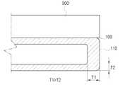
도 3은 본 발명의 실시예에 따른 열교환기용 튜브가 헤더탱크에 삽입된 상태를 나타낸 평면도이며, 도 4는 본 발명의 실시예에 따른 열교환기용 튜브를 나타낸 정면도이고, 도 5는 본 발명의 실시예에 따른 열교환기용 튜브를 나타낸 사시도이며, 도 6은 본 발명의 실시예에 따른 열교환기를 나타낸 사시도이고, 도 7은 본 발명의 실시예에 따른 열교환기를 나타낸 분해사시도이며, 도 8은 본 발명의 실시예에 따른 열교환기에서 튜브가 헤더탱크에 삽입되는 과정을 나타낸 평면도이다.FIG. 3 is a plan view showing a state where a tube for a heat exchanger according to an embodiment of the present invention is inserted into a header tank, FIG. 4 is a front view showing a tube for a heat exchanger according to an embodiment of the present invention, and FIG. FIG. 6 is a perspective view of a heat exchanger according to an embodiment of the present invention, FIG. 7 is an exploded perspective view illustrating a heat exchanger according to an embodiment of the present invention, FIG. 8 is a cross- 1 is a plan view illustrating a process of inserting a tube into a header tank in a heat exchanger according to an embodiment of the present invention.
도 4 및 도 5에 도시된 바와 같이, 본 발명에 따른 열교환기용 튜브(100)는 다수개 구비되어 열교환기(1) 내부를 순환하는 열교환매체의 유로를 형성하는 것으로, 길이방향으로 양측 단부의 폭방향 직경이 점차 줄어들도록 가공된 챔퍼부(110)를 포함한다.4 and 5, a plurality of
상기 챔퍼부(110)는 상기 튜브(100)의 양측 단부 직경이, 나머지 영역보다 작아지도록 가공된 것으로, 도 3에서 A1이 가리키는 단면보다, A2 단면이 작도록 기울기 갖게 된다.The chamfered
또한, 열교환기(1)의 튜브(100) 및 핀(300)으로 이루어진 코어 조립 시, 헤더(201) 폭은 약 ±2m의 편차가 발생하므로, 이를 감안하여 상기 챔퍼부(110)는 길이가 2mm~4mm인 것이 바람직하다.The width of the
이에 따라, 본 발명에 따른 열교환기용 튜브(100)는 헤더(201)의 튜브삽입홀(203)에 원활하게 삽입됨으로써, 조립성이 향상될 수 있다.Accordingly, the
본 발명의 튜브(100)가 적용되는 열교환기(1)의 구조를 먼저 살펴보면,The structure of the
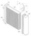
상기 열교환기(1)는 크게, 일정거리 이격되어 나란하게 배치되는 한 쌍의 헤더탱크(210)와, 상기 헤더탱크(210)에 양단이 고정되는 튜브(100)와, 상기 튜브(100) 사이에 개재되는 핀(300)을 포함하여 형성된다.The
도 6에 도시된 상기 열교환기(1)는 길이방향으로 일정거리 이격되어 나란하게 형성되는 한 쌍의 헤더탱크(210)를 포함하며, 상기 헤더탱크(210)는 헤더(201)와 탱크(202)의 조립에 의해 형성된다.6 includes a pair of
상기 열교환기(1)는 한 쌍의 헤더탱크(210)에 형성되며, 열교환매체가 유입되는 입구파이프(410) 및 배출되는 출구파이프(420)를 더 포함하여 형성된다.The
상기 튜브(100)는 한 쌍의 헤더탱크(210)에 양 단이 고정되어 열교환매체의 유로를 형성하며, 높이방향으로 일정간격 이격되어 병렬 배치된다.The
상기 핀(300)은 상기 튜브(100) 사이에 개재되어 상기 튜브(100) 사이를 흐르는 공기와의 전열면적을 증가시키며, 일정한 상기 튜브(100) 사이 공간에 최대한 큰 전열면적이 구비되도록 하기 위해 상ㆍ하로 절곡되어 코루게이트(Corrugate) 타입으로 형성된다.The
상술한 바와 같이, 상기 핀(300)은 상기 튜브(100) 사이에 개재되어 상기 튜브(100)와 접촉하는 영역에서 발생되는 전도에 의한 전열 현상으로 인해, 열교환매체 및 공기의 열교환기(1) 이루어지도록 하게 된다.As described above, since the
이때, 전열면적은 상기 핀(300) 및 튜브(100)의 접촉 면적이 늘어날수록 증대되므로, 열교환성능은 핀(300) 및 튜브(100)의 접촉 면적이 최대한 클수록 좋다.At this time, the heat transfer area increases as the contact area of the
이를 위해, 본 발명의 열교환기용 튜브(100)는 핀(300)과 접촉되는 면의 폭방향으로 일측 단부에서부터 타측 단부까지가 편평하게 형성될 수 있다. 이때, 본 발명의 열교환기용 튜브(100)는 단면이 대략 직사각 형태를 이루며, 각 모서리는 최소한의 라운드로 주어 핀(300) 끝단과의 접촉면적을 일치시키는 것이 바람직하다.To this end, the
즉, 본 발명의 열교환기용 튜브(100)는 핀(300)과 접촉되는 면의 길이가 서로 동일하게 형성됨으로써, 종래에 외측 라운드를 갖는 튜브(100)에 비해 전열 면적이 증대되고, 열교환 성능을 향상시킬 수 있다는 장점이 있다.That is, the
그런데, 상술한 바와 같은 사각 단면을 갖는 튜브(100)는 양단에 라운드가 형성된 튜브(100)보다, 헤더(201)의 튜브삽입홀(203)에 삽입 시, 조립이 원활히 되지 않는 단점이 있다.However, the
따라서 본 발명은 사각 단면을 갖는 튜브(100)의 조립이 용이하도록 길이방향으로 양측 단부에 상기 챔버부가 형성되도록 하여 필요한 양만큼 튜브(100)가 헤더탱크(210) 내부에 삽입되도록 한다.Accordingly, the present invention allows the
이때, 상기 헤더탱크(210)의 헤더(201)에는 상기 튜브(100)가 삽입되는 튜브삽입홀(203)이 상기 핀(300)과 접하는 영역에 배치되는 튜브(100)의 단면과 대응되도록 형성된다. 즉, 상기 열교환기용 튜브(100)는 챔퍼부(110)가 형성되지 않은 지점이 상기 튜브삽입홀(203)에 결합 고정되므로, 상기 튜브삽입홀(203)은 상기 챔퍼부(110)가 형성되지 않은 영역의 튜브(100) 단면에 대응되는 형태로 형성되는 것이 바람직하다.A
또한, 도8에 도시된 것처럼, 상기 헤더탱크(210)의 헤더(201)에는 상기 튜브삽입홀(203)의 폭방향으로 양단에 상기 튜브(100)가 삽입되는 방향과 반대방향으로 돌출되는 가이드부가 형성될 수 있다.8, the
상기 헤더(201)는 펀칭 또는 프레스 가공을 통해 튜브삽입홀(203)이 형성되는데, 이 과정에서 알루미늄 부재가 제거된 튜브삽입홀(203)의 폭방향으로 양단에 잔존하는 알루미늄 부재가 남아 가이드부(500)를 형성하며, 상기 가이드부는 상기 튜브삽입홀(203)이 삽입되는 경로를 안내해주는 역할을 하게 된다.The
상기 가이드부(500)는 상기 튜브(100)의 삽입방향으로 경사진 형태를 가지는 것이 바람직하며, 상기 헤더(201)는 상술한 바와 같이 알루미늄 외에 다른 재료로 얼마든지 변경실시가 가능하다.The
이에 따라, 본 발명은 튜브(100) 빠짐에 의한 누수와 튜브(100) 과삽입에 의한 열교환기(1)의 성능 저하와 같은 품질 문제 개선 효과를 가질 수 있다.Accordingly, the present invention can have an effect of improving the quality problem, such as leakage of water from the
또한, 상기 튜브(100)는 압출 성형으로 제조될 수 있어 폴디드(folded) 튜브(100)나 웰디드(welded) 튜브(100)보다 간편하게 제조가 가능하며, 기밀유지 및 압력 저항성이 뛰어나다는 장점이 있다.The
한편, 상기 튜브(100)는 길이방향으로 양측에 위치한 면의 두께(T1)와, 너비방향으로 양측에 위치한 면의 두께(T2)가 동일하게 형성될 수도 있으며, 도 5와 같이 길이방향으로 양측에 위치한 면의 두께(T1)가, 너비방향으로 양측에 위치한 면의 두께(T2)보다 두껍게 형성될 수도 있다.The
이에 따라, 본 발명의 열교환기용 튜브(100)는 주행 중 부식물질이나 이물질과 접촉되기 쉬운 영역을 다른 영역보다 두껍게 형성하여, 부식물질 또는 이물질에 의한 손상에 의해 누수가 발생되는 문제를 최소화시킬 수 있으며, 내구성 향상에 기여할 수 있다는 장점이 있다.Accordingly, the
또한, 본 발명의 열교환기용 튜브(100)에는 냉매유동공간을 길이방향으로 분리하는 다수개의 격벽(120)이 형성될 수도 있다. 도 8에 도시된 바와 같이, 상기 격벽(120)은 튜브(100) 내부 공간이 길이방향으로 다수개의 공간으로 분리되도록 형성될 수 있으며, 튜브(100) 내압성을 향상시킬 수 있다.In the
본 발명의 열교환기용 튜브(100)를 포함하는 열교환기(1)를 제조하는 방법을 설명하면, 먼저 이용되는 각 부품을 제조한다.A method of manufacturing the
이는 상기 제1헤더탱크(210) 및 제2헤더탱크(220)를 형성하는 헤더(201)와 탱크(202), 튜브(100) 및 핀(300) 등의 구성을 준비하는 것으로, 본 발명의 열교환기용 튜브(100)는 상술한 바와 같이 편평하게 형성되어 단면이 사각 형태를 가지며, 길이방향으로 양단에 엔드포밍(end forming)과 같은 챔퍼부(110)가 가공된다.The
이때, 본 발명의 열교환기용 튜브(100)는 압출 성형을 통해 제조되는 것이 바람직하며, 내부에 적어도 하나 이상의 격벽(120)이 형성도록 하는 것이 좋다.At this time, it is preferable that the
다음으로, 브레이징을 통해 상기 헤더(201), 튜브(100) 및 핀(300) 조립체를 형성하는데, 상기 헤더(201)의 튜브삽입홀(203)에 형성된 가이드부를 따라 상기 튜브(100)의 챔퍼부(110)가 삽입 결합된다.Next, brazing is performed to form the
다음으로, 상기 헤더(201), 튜브(100) 및 핀(300) 조립체와, 상기 제1헤더탱크(210) 및 제2헤더탱크(220)를 고정하여 열교환기(1)를 제조한다.Next, the
본 발명은 상기한 실시예에 한정되지 아니하며, 적용범위가 다양함은 물론이고, 청구범위에서 청구하는 본 발명의 요지를 벗어남이 없이 당해 본 발명이 속하는 분야에서 통상의 지식을 가진 자라면 누구든지 다양한 변형 실시가 가능한 것은 물론이다.It will be understood by those skilled in the art that various changes in form and details may be made therein without departing from the spirit and scope of the invention as defined by the appended claims. It goes without saying that various modifications can be made.
1 : 열교환기
100 : 튜브
110 : 챔퍼부
120 : 격벽
201 : 헤더
202 : 탱크
203 : 튜브삽입홀
210 : 헤더탱크
300 : 핀
410 : 입구파이프
420 : 출구파이프
500 : 가이드부1: Heat exchanger
100: tube
110:
120:
201: Header
202: tank
203: tube insertion hole
210: header tank
300: pin
410: inlet pipe
420: outlet pipe
500: guide portion
Claims (12)
Translated fromKorean상기 튜브(100)는
길이방향으로 양측 단부의 폭방향 직경이 점차 줄어들도록 가공된 챔퍼부(110)를 포함하는 것을 특징으로 하는 열교환기용 튜브.
A heat exchanger tube (100) comprising a plurality of heat exchanger (1) and forming a flow path of a heat exchange medium circulating inside the heat exchanger (1)
The tube (100)
And a chamfered portion (110) machined such that the widthwise diameters of both ends in the longitudinal direction are gradually reduced.
상기 튜브(100)는
이웃한 튜브(100) 사이에 개재되는 핀(300)과 접촉되는 면이, 폭방향으로 일측 단부에서 타측 단부까지 편평하게 형성되는 것을 특징으로 하는 열교환기용 튜브.
The method according to claim 1,
The tube (100)
Wherein a surface that is in contact with a fin (300) interposed between adjacent tubes (100) is formed flat from one side end to the other side in the width direction.
상기 튜브(100)는
냉매유동공간을 폭방향으로 분리하는 다수개의 격벽(120)을 포함하는 것을 특징으로 하는 열교환기용 튜브.
3. The method of claim 2,
The tube (100)
And a plurality of partitions (120) for separating the refrigerant flow space in the width direction.
상기 튜브(100)는
폭 방향으로 양측에 위치한 면의 두께가, 두께 방향으로 양측에 위치한 면의 두께보다 두꺼운 것을 특징으로 하는 열교환기용 튜브.
The method of claim 3,
The tube (100)
Wherein the thicknesses of the faces located on both sides in the width direction are thicker than the thicknesses of the faces located on both sides in the thickness direction.
상기 챔퍼부(110)는
길이가 2mm~4mm인 것을 특징으로 하는 열교환기용 튜브.
The method according to claim 1,
The chamfered portion 110
And a length of 2 mm to 4 mm.
상기 튜브(100)는
상기 챔퍼부(110)가 시작되는 A1이 가리키는 단면 및 끝나는 A2가 가리키는 단면이 사각 형태인 것을 특징으로 하는 열교환기용 튜브.
The method according to claim 1,
The tube (100)
Characterized in that the cross-section indicated by A1 at which the chamfered portion (110) starts and the cross-section indicated by A2 at the end are square.
상기 챔퍼부(110) 면이 사각형인 것을 특징으로 하는 열교환기용 튜브.
The method according to claim 6,
Wherein a surface of the chamber (110) is rectangular.
상기 헤더탱크(210)에 양단이 고정되며, 제1항 내지 제7항 중 어느 한 항에 의한 튜브(100); 및
상기 튜브(100) 사이에 개재되는 코루게이트(Corrugate) 타입의 핀(300); 을 포함하는 열교환기.
A pair of header tanks 210 spaced apart from each other by a predetermined distance;
A tube (100) according to any one of claims 1 to 7, both ends of which are fixed to the header tank (210); And
A pin 300 of a corrugate type interposed between the tubes 100; ≪ / RTI >
상기 튜브(100) 및 핀(300)은
폭방향으로 접촉되는 면의 길이가 서로 동일한 것을 특징으로 하는 열교환기.
9. The method of claim 8,
The tube (100) and the pin (300)
And the lengths of the surfaces contacting in the width direction are equal to each other.
상기 헤더탱크(210)의 헤더(201)에는
상기 튜브(100)가 삽입되는 튜브삽입홀(203)이 상기 핀(300)과 접하는 영역에 배치되는 튜브(100)의 단면과 대응되도록 형성되는 것을 특징으로 하는 열교환기.
9. The method of claim 8,
In the header 201 of the header tank 210,
Wherein a tube insertion hole (203) into which the tube (100) is inserted is formed to correspond to an end surface of the tube (100) disposed in an area in contact with the fin (300).
상기 헤더탱크(210)의 헤더(201)에는
상기 튜브삽입홀(203)의 폭방향으로 양단에 상기 튜브(100)가 삽입되는 방향과 반대방향으로 돌출되는 가이드부(500)가 형성되는 것을 특징으로 하는 열교환기.
11. The method of claim 10,
In the header 201 of the header tank 210,
And a guide part (500) protruding in a direction opposite to a direction in which the tube (100) is inserted is formed at both ends in the width direction of the tube insertion hole (203).
상기 가이드부(500)는 상기 헤더(201)와 상기 튜브(100)가 서로 접합되는 일부분을 감싸도록 상기 헤더탱크(210)의 외측 공간으로 돌출되는 것을 특징으로 하는 열교환기.12. The method of claim 11,
Wherein the guide part (500) protrudes into an outer space of the header tank (210) so as to enclose a part where the header (201) and the tube (100) are joined to each other.
Priority Applications (1)
| Application Number | Priority Date | Filing Date | Title |
|---|---|---|---|
| KR1020190078778AKR102350040B1 (en) | 2016-07-06 | 2019-07-01 | A tube of heat exchanger and heat exchanger with the same |
Applications Claiming Priority (2)
| Application Number | Priority Date | Filing Date | Title |
|---|---|---|---|
| KR1020160085436AKR20180005405A (en) | 2016-07-06 | 2016-07-06 | A tube of heat exchanger and heat exchanger with the same |
| KR1020190078778AKR102350040B1 (en) | 2016-07-06 | 2019-07-01 | A tube of heat exchanger and heat exchanger with the same |
Related Parent Applications (1)
| Application Number | Title | Priority Date | Filing Date |
|---|---|---|---|
| KR1020160085436ADivisionKR20180005405A (en) | 2016-07-06 | 2016-07-06 | A tube of heat exchanger and heat exchanger with the same |
Publications (2)
| Publication Number | Publication Date |
|---|---|
| KR20190082182Atrue KR20190082182A (en) | 2019-07-09 |
| KR102350040B1 KR102350040B1 (en) | 2022-01-12 |
Family
ID=79339713
Family Applications (1)
| Application Number | Title | Priority Date | Filing Date |
|---|---|---|---|
| KR1020190078778AActiveKR102350040B1 (en) | 2016-07-06 | 2019-07-01 | A tube of heat exchanger and heat exchanger with the same |
Country Status (1)
| Country | Link |
|---|---|
| KR (1) | KR102350040B1 (en) |
Citations (5)
| Publication number | Priority date | Publication date | Assignee | Title |
|---|---|---|---|---|
| JPH09324997A (en)* | 1996-06-05 | 1997-12-16 | Toshiba Corp | Heat exchanger and method for manufacturing heat exchanger |
| KR19980048652A (en)* | 1996-12-18 | 1998-09-15 | 구자홍 | Heat exchanger for evaporator |
| JP2002130983A (en)* | 2000-10-26 | 2002-05-09 | Toyo Radiator Co Ltd | Extruded tube having multiple minute holes for heat exchanger, and heat exchanger |
| JP2007093144A (en)* | 2005-09-29 | 2007-04-12 | Denso Corp | Heat exchanging tube and heat exchanger |
| KR20130016982A (en) | 2011-08-09 | 2013-02-19 | 한국에너지기술연구원 | Movable infrared heater |
- 2019
- 2019-07-01KRKR1020190078778Apatent/KR102350040B1/enactiveActive
Patent Citations (5)
| Publication number | Priority date | Publication date | Assignee | Title |
|---|---|---|---|---|
| JPH09324997A (en)* | 1996-06-05 | 1997-12-16 | Toshiba Corp | Heat exchanger and method for manufacturing heat exchanger |
| KR19980048652A (en)* | 1996-12-18 | 1998-09-15 | 구자홍 | Heat exchanger for evaporator |
| JP2002130983A (en)* | 2000-10-26 | 2002-05-09 | Toyo Radiator Co Ltd | Extruded tube having multiple minute holes for heat exchanger, and heat exchanger |
| JP2007093144A (en)* | 2005-09-29 | 2007-04-12 | Denso Corp | Heat exchanging tube and heat exchanger |
| KR20130016982A (en) | 2011-08-09 | 2013-02-19 | 한국에너지기술연구원 | Movable infrared heater |
Also Published As
| Publication number | Publication date |
|---|---|
| KR102350040B1 (en) | 2022-01-12 |
Similar Documents
| Publication | Publication Date | Title |
|---|---|---|
| US8074708B2 (en) | Heat exchanger | |
| US20070227715A1 (en) | Heat exchanger | |
| JP2007298197A (en) | Heat exchanger | |
| JP2009063228A (en) | Flat heat transfer tube | |
| US20080000627A1 (en) | Heat exchanger | |
| US20080245513A1 (en) | Tube for heat exchanger and method of manufacturing tube | |
| US6253840B1 (en) | Refrigerant evaporator including refrigerant passage with inner fin | |
| JP2010121925A (en) | Heat exchanger | |
| US20230168039A1 (en) | Heat exchanger | |
| KR102703322B1 (en) | Heat exchanger | |
| KR20110112626A (en) | Manifold for Heat Exchanger | |
| KR20090096030A (en) | Return tube and heat exchanger comprising the same | |
| JP2006078163A (en) | Flat tube, plate body for manufacturing flat tube, and heat exchanger | |
| JP2018044707A (en) | Heat exchanger | |
| KR20190082182A (en) | A tube of heat exchanger and heat exchanger with the same | |
| JPH05215482A (en) | Heat exchanger | |
| KR20180005405A (en) | A tube of heat exchanger and heat exchanger with the same | |
| KR101543522B1 (en) | Flate tube for heat exchanger and heat exchanger with the same | |
| JP5851846B2 (en) | Heat exchanger and manufacturing method thereof | |
| KR101982748B1 (en) | A tube of heat exchanger | |
| KR20170044965A (en) | A tube of heat exchanger | |
| KR100740698B1 (en) | Heat exchanger header pipe | |
| US20190353426A1 (en) | Side member and heat exchanger having the same | |
| US20060048930A1 (en) | Heat exchanger | |
| KR20090096028A (en) | Heat exchanger |
Legal Events
| Date | Code | Title | Description |
|---|---|---|---|
| A107 | Divisional application of patent | ||
| PA0107 | Divisional application | Comment text:Divisional Application of Patent Patent event date:20190701 Patent event code:PA01071R01D Filing date:20160706 Application number text:1020160085436 | |
| PG1501 | Laying open of application | ||
| A201 | Request for examination | ||
| PA0201 | Request for examination | Patent event code:PA02012R01D Patent event date:20210706 Comment text:Request for Examination of Application Patent event code:PA02011R04I Patent event date:20190701 Comment text:Divisional Application of Patent | |
| E902 | Notification of reason for refusal | ||
| PE0902 | Notice of grounds for rejection | Comment text:Notification of reason for refusal Patent event date:20210730 Patent event code:PE09021S01D | |
| E701 | Decision to grant or registration of patent right | ||
| PE0701 | Decision of registration | Patent event code:PE07011S01D Comment text:Decision to Grant Registration Patent event date:20211222 | |
| PR0701 | Registration of establishment | Comment text:Registration of Establishment Patent event date:20220106 Patent event code:PR07011E01D | |
| PR1002 | Payment of registration fee | Payment date:20220107 End annual number:3 Start annual number:1 | |
| PG1601 | Publication of registration |