KR20190078595A - A micro-perforated panel system, an application, and a method of manufacturing a micro-perforated panel system - Google Patents
A micro-perforated panel system, an application, and a method of manufacturing a micro-perforated panel systemDownload PDFInfo
- Publication number
- KR20190078595A KR20190078595AKR1020197014351AKR20197014351AKR20190078595AKR 20190078595 AKR20190078595 AKR 20190078595AKR 1020197014351 AKR1020197014351 AKR 1020197014351AKR 20197014351 AKR20197014351 AKR 20197014351AKR 20190078595 AKR20190078595 AKR 20190078595A
- Authority
- KR
- South Korea
- Prior art keywords
- panel
- glass
- micro
- diameter
- glass ceramic
- Prior art date
- Legal status (The legal status is an assumption and is not a legal conclusion. Google has not performed a legal analysis and makes no representation as to the accuracy of the status listed.)
- Withdrawn
Links
- 238000004519manufacturing processMethods0.000titleabstractdescription10
- 239000011521glassSubstances0.000claimsabstractdescription223
- 238000000034methodMethods0.000claimsabstractdescription114
- 230000009467reductionEffects0.000claimsabstractdescription11
- 239000002241glass-ceramicSubstances0.000claimsdescription153
- 238000010521absorption reactionMethods0.000claimsdescription63
- 238000005530etchingMethods0.000claimsdescription28
- 239000002253acidSubstances0.000claimsdescription23
- 238000000926separation methodMethods0.000claimsdescription20
- 239000007787solidSubstances0.000claimsdescription12
- 239000006112glass ceramic compositionSubstances0.000claimsdescription6
- 230000002093peripheral effectEffects0.000claimsdescription2
- 230000003014reinforcing effectEffects0.000claimsdescription2
- 230000009977dual effectEffects0.000description36
- 230000008569processEffects0.000description28
- 239000000047productSubstances0.000description21
- 239000000463materialSubstances0.000description12
- 238000013461designMethods0.000description11
- 238000012360testing methodMethods0.000description11
- 230000000694effectsEffects0.000description9
- 230000003287optical effectEffects0.000description9
- 239000005341toughened glassSubstances0.000description9
- 238000009792diffusion processMethods0.000description8
- KRHYYFGTRYWZRS-UHFFFAOYSA-NFluoraneChemical compoundFKRHYYFGTRYWZRS-UHFFFAOYSA-N0.000description7
- 230000006835compressionEffects0.000description7
- 238000007906compressionMethods0.000description7
- 238000009826distributionMethods0.000description7
- 238000006243chemical reactionMethods0.000description5
- 238000005553drillingMethods0.000description5
- 230000001965increasing effectEffects0.000description5
- 150000002500ionsChemical class0.000description5
- 238000005496temperingMethods0.000description5
- 238000001816coolingMethods0.000description4
- 230000007547defectEffects0.000description4
- 239000000203mixtureSubstances0.000description4
- 230000008092positive effectEffects0.000description4
- 239000000758substrateSubstances0.000description4
- GRYLNZFGIOXLOG-UHFFFAOYSA-NNitric acidChemical compoundO[N+]([O-])=OGRYLNZFGIOXLOG-UHFFFAOYSA-N0.000description3
- 239000006096absorbing agentSubstances0.000description3
- 230000008901benefitEffects0.000description3
- 239000006227byproductSubstances0.000description3
- 239000000919ceramicSubstances0.000description3
- 239000011248coating agentSubstances0.000description3
- 238000000576coating methodMethods0.000description3
- 230000006870functionEffects0.000description3
- 238000005342ion exchangeMethods0.000description3
- QPJSUIGXIBEQAC-UHFFFAOYSA-Nn-(2,4-dichloro-5-propan-2-yloxyphenyl)acetamideChemical compoundCC(C)OC1=CC(NC(C)=O)=C(Cl)C=C1ClQPJSUIGXIBEQAC-UHFFFAOYSA-N0.000description3
- 229910017604nitric acidInorganic materials0.000description3
- 239000005361soda-lime glassSubstances0.000description3
- 239000000126substanceSubstances0.000description3
- 238000000862absorption spectrumMethods0.000description2
- 238000013019agitationMethods0.000description2
- 238000004458analytical methodMethods0.000description2
- 238000003491arrayMethods0.000description2
- 230000007797corrosionEffects0.000description2
- 238000005260corrosionMethods0.000description2
- 238000011161developmentMethods0.000description2
- 238000010586diagramMethods0.000description2
- -1e.g.Substances0.000description2
- 230000002708enhancing effectEffects0.000description2
- 238000010438heat treatmentMethods0.000description2
- 238000009434installationMethods0.000description2
- 238000012986modificationMethods0.000description2
- 230000004048modificationEffects0.000description2
- 239000011148porous materialSubstances0.000description2
- 238000007679ring-on-ring testMethods0.000description2
- 238000001228spectrumMethods0.000description2
- 229910000760Hardened steelInorganic materials0.000description1
- 230000005374Kerr effectEffects0.000description1
- 238000005299abrasionMethods0.000description1
- 239000003513alkaliSubstances0.000description1
- 239000005358alkali aluminosilicate glassSubstances0.000description1
- 230000000845anti-microbial effectEffects0.000description1
- 230000003667anti-reflective effectEffects0.000description1
- 239000004599antimicrobialSubstances0.000description1
- 238000013459approachMethods0.000description1
- 230000006399behaviorEffects0.000description1
- 238000005422blastingMethods0.000description1
- 239000002419bulk glassSubstances0.000description1
- 230000015556catabolic processEffects0.000description1
- 238000003486chemical etchingMethods0.000description1
- 238000003426chemical strengthening reactionMethods0.000description1
- 238000005336crackingMethods0.000description1
- 238000005520cutting processMethods0.000description1
- 238000007405data analysisMethods0.000description1
- 230000007423decreaseEffects0.000description1
- 239000003814drugSubstances0.000description1
- 238000002592echocardiographyMethods0.000description1
- 230000002349favourable effectEffects0.000description1
- 239000002657fibrous materialSubstances0.000description1
- 239000005357flat glassSubstances0.000description1
- 229910052731fluorineInorganic materials0.000description1
- 239000011737fluorineSubstances0.000description1
- 239000006260foamSubstances0.000description1
- 235000013305foodNutrition0.000description1
- 230000009477glass transitionEffects0.000description1
- 239000002920hazardous wasteSubstances0.000description1
- 208000016354hearing loss diseaseDiseases0.000description1
- 230000002209hydrophobic effectEffects0.000description1
- 230000003993interactionEffects0.000description1
- 238000005259measurementMethods0.000description1
- 230000007246mechanismEffects0.000description1
- 230000003340mental effectEffects0.000description1
- 238000001000micrographMethods0.000description1
- 150000007522mineralic acidsChemical group0.000description1
- XLYOFNOQVPJJNP-UHFFFAOYSA-OoxoniumChemical compound[OH3+]XLYOFNOQVPJJNP-UHFFFAOYSA-O0.000description1
- 229920000515polycarbonatePolymers0.000description1
- 239000004417polycarbonateSubstances0.000description1
- 238000012545processingMethods0.000description1
- 238000005086pumpingMethods0.000description1
- 230000036632reaction speedEffects0.000description1
- 230000004044responseEffects0.000description1
- 230000000284resting effectEffects0.000description1
- 239000005336safety glassSubstances0.000description1
- 150000003839saltsChemical class0.000description1
- 230000003678scratch resistant effectEffects0.000description1
- 238000007650screen-printingMethods0.000description1
- 230000003595spectral effectEffects0.000description1
- 238000007655standard test methodMethods0.000description1
- 238000003756stirringMethods0.000description1
- 238000006467substitution reactionMethods0.000description1
- 238000007669thermal treatmentMethods0.000description1
- XLYOFNOQVPJJNP-UHFFFAOYSA-NwaterSubstancesOXLYOFNOQVPJJNP-UHFFFAOYSA-N0.000description1
- 238000004383yellowingMethods0.000description1
Images


Classifications
- C—CHEMISTRY; METALLURGY
- C03—GLASS; MINERAL OR SLAG WOOL
- C03C—CHEMICAL COMPOSITION OF GLASSES, GLAZES OR VITREOUS ENAMELS; SURFACE TREATMENT OF GLASS; SURFACE TREATMENT OF FIBRES OR FILAMENTS MADE FROM GLASS, MINERALS OR SLAGS; JOINING GLASS TO GLASS OR OTHER MATERIALS
- C03C15/00—Surface treatment of glass, not in the form of fibres or filaments, by etching
- C—CHEMISTRY; METALLURGY
- C03—GLASS; MINERAL OR SLAG WOOL
- C03B—MANUFACTURE, SHAPING, OR SUPPLEMENTARY PROCESSES
- C03B33/00—Severing cooled glass
- C03B33/02—Cutting or splitting sheet glass or ribbons; Apparatus or machines therefor
- C03B33/0222—Scoring using a focussed radiation beam, e.g. laser
- C—CHEMISTRY; METALLURGY
- C03—GLASS; MINERAL OR SLAG WOOL
- C03C—CHEMICAL COMPOSITION OF GLASSES, GLAZES OR VITREOUS ENAMELS; SURFACE TREATMENT OF GLASS; SURFACE TREATMENT OF FIBRES OR FILAMENTS MADE FROM GLASS, MINERALS OR SLAGS; JOINING GLASS TO GLASS OR OTHER MATERIALS
- C03C23/00—Other surface treatment of glass not in the form of fibres or filaments
- C03C23/0005—Other surface treatment of glass not in the form of fibres or filaments by irradiation
- C03C23/0025—Other surface treatment of glass not in the form of fibres or filaments by irradiation by a laser beam
- G—PHYSICS
- G10—MUSICAL INSTRUMENTS; ACOUSTICS
- G10K—SOUND-PRODUCING DEVICES; METHODS OR DEVICES FOR PROTECTING AGAINST, OR FOR DAMPING, NOISE OR OTHER ACOUSTIC WAVES IN GENERAL; ACOUSTICS NOT OTHERWISE PROVIDED FOR
- G10K11/00—Methods or devices for transmitting, conducting or directing sound in general; Methods or devices for protecting against, or for damping, noise or other acoustic waves in general
- G10K11/16—Methods or devices for protecting against, or for damping, noise or other acoustic waves in general
- G10K11/162—Selection of materials
- E—FIXED CONSTRUCTIONS
- E04—BUILDING
- E04B—GENERAL BUILDING CONSTRUCTIONS; WALLS, e.g. PARTITIONS; ROOFS; FLOORS; CEILINGS; INSULATION OR OTHER PROTECTION OF BUILDINGS
- E04B1/00—Constructions in general; Structures which are not restricted either to walls, e.g. partitions, or floors or ceilings or roofs
- E04B1/62—Insulation or other protection; Elements or use of specified material therefor
- E04B1/74—Heat, sound or noise insulation, absorption, or reflection; Other building methods affording favourable thermal or acoustical conditions, e.g. accumulating of heat within walls
- E04B1/82—Heat, sound or noise insulation, absorption, or reflection; Other building methods affording favourable thermal or acoustical conditions, e.g. accumulating of heat within walls specifically with respect to sound only
- E04B1/84—Sound-absorbing elements
- E04B2001/8423—Tray or frame type panels or blocks, with or without acoustical filling
- E04B2001/8433—Tray or frame type panels or blocks, with or without acoustical filling with holes in their face
Landscapes
- Chemical & Material Sciences (AREA)
- Engineering & Computer Science (AREA)
- Organic Chemistry (AREA)
- Materials Engineering (AREA)
- General Chemical & Material Sciences (AREA)
- Geochemistry & Mineralogy (AREA)
- Life Sciences & Earth Sciences (AREA)
- Chemical Kinetics & Catalysis (AREA)
- Physics & Mathematics (AREA)
- Optics & Photonics (AREA)
- Health & Medical Sciences (AREA)
- Toxicology (AREA)
- Acoustics & Sound (AREA)
- Multimedia (AREA)
- Surface Treatment Of Glass (AREA)
- Soundproofing, Sound Blocking, And Sound Damping (AREA)
- Joining Of Glass To Other Materials (AREA)
- Re-Forming, After-Treatment, Cutting And Transporting Of Glass Products (AREA)
Abstract
Translated fromKoreanDescription
Translated fromKorean관련 출원에 대한 상호-참조Cross-reference to related application
본 출원은 내용이 본원에 의존되고 내용 전체가 참조로서 본원에 포함된 2016년 11월 4일 출원된 미국 가출원 제 62/417,411 호의 35 U.S.C. § 119 하의 우선권의 이익을 주장한다.This application claims the benefit of U. S. Provisional Application No. 62 / 417,411, filed November 4, 2016, the content of which is hereby incorporated by reference herein in its entirety. Claims of priority under § 119.
기술된 구체예는 일반적으로 마이크로-퍼포레이팅된 패널 시스템, 노이즈 저감 방법, 및 마이크로-퍼포레이팅된 패널 시스템의 제조 방법에 관한 것이다. 특히, 구체예는 유리 마이크로-퍼포레이팅된 패널 시스템 및 노이즈 저감 방법에 관한 것이다. 패널 시스템은 고체 뒷벽(back wall)과 함께 또는 고체 뒷벽 없이 사용될 수 있다.The described embodiments generally relate to a micro-perforated panel system, a noise reduction method, and a method of manufacturing a micro-perforated panel system. In particular, embodiments relate to glass micro-perforated panel systems and noise reduction methods. The panel system can be used with a solid back wall or without a solid back wall.
유리는 우수한 광학적 특성, 내스크래치성 및 내부식성, 내구성, 방수성, 미적 품질, 내화성 등으로 인해 매우 바람직한 건축용 제품이다. 예를 들어, 폴리카보네이트와 같은 중합성 물질과 달리, 유리는 시간에 따라 "황변(yellow)"되지 않으며, 높은 강도 및 내스크래치성을 갖고, UV 방법을 사용하여 세척될 수 있다. 그러나, 유리의 높은 밀도 및 음향 임피던스(impedance)는 높은 음향 반사(예를 들어, 에코), 불량한 조음 명료도(speech intelligibility), 및 낮은 감음 계수(noise reduction coefficient, NRC)를 야기하며, 이는 특히 건축 적용에서의 광범위한 사용을 제한한다. 보통의 유리는 흠음 계수가 거의 없고(약 0.05의 NRC), 이는 사용 시 바람직하지 않게 긴 잔향 시간 및 불량한 음향 환경을 초래한다.Glass is a highly desirable architectural product due to its excellent optical properties, scratch resistance and corrosion resistance, durability, waterproofness, aesthetic quality and fire resistance. For example, unlike polymeric materials such as polycarbonate, the glass does not "yellow" over time, has high strength and scratch resistance, and can be cleaned using the UV method. However, the high density and acoustic impedance of the glass result in high acoustic reflection (e. G. Echo), poor speech intelligibility, and low noise reduction coefficient (NRC) Limit extensive use in applications. Normal glasses have very few scratch coefficients (about 0.05 NRC), which undesirably leads to long reverberation times and poor acoustic environments.
최적의 실내 음향을 확립하는 것은 예를 들어, 개방된 사무실 공간, 병원, 교실, 공항, 자동차 적용 등과 같은 것을 포함하는 많은 내부 건축 적용에 대한 증가하는 수요가 되어왔다. 85 데시벨(dB)보다 큰 음향 수준에 대한 지속적인 노출은 청력 손상을 야기할 수 있을 뿐 아니라, 훨씬 낮은 수준에서도 노이즈는 상당한 정신 산란일 수 있으며 감소된 생산성, 감소된 집중 또는 휴식 능력을 야기할 수 있고, 일반적으로 실내를 음향적으로 불쾌하게 만들 수 있다.Establishing optimal room acoustics has been an increasing demand for many interior architectural applications, including, for example, open office spaces, hospitals, classrooms, airports, automotive applications, and the like. Continuous exposure to acoustic levels greater than 85 decibels (dB) may not only cause hearing impairment, but also at a much lower level, noise can be significant mental spawning and result in reduced productivity, reduced focus, or resting ability And can generally make the room uncomfortably acoustically.
흡음에 대한 현재의 접근법은 음향 폼(foam), 섬유 물질, 및 다른 비-투명, 비-유리 물질의 사용을 포함한다. 기술적인 해결책이 노이즈 제어가 바람직한 다양한 작동 가능한 환경에서 사용되는 유리의 NRC 등급을 포함하는 음향 특성을 향상시키는데 요구된다.Current approaches to sound absorption include the use of acoustic foams, fibrous materials, and other non-transparent, non-glass materials. A technical solution is required to improve acoustic properties, including the NRC rating of glass used in various operable environments where noise control is desirable.
본 개시는 유리의 바람직한 특성(예를 들어, 우수한 광학적 특성, 내스크래치성 및 내부식성, 내구성, 방수 특성, 미적 품질, 내화성, 비-황변(non-yellowing), 고강도, 및 UV 방법을 사용하여 세척되는 능력 등)을 유지하면서 노이즈 저감 및 음향 제어에 사용될 수 있는 마이크로-퍼포레이팅된 유리 또는 유리 세라믹 제품을 제공한다. 본 개시의 몇몇 구체예는 소정의 두께를 갖는 유리 또는 유리 세라믹 패널을 포함하는 제품에 관한 것이고, 여기서 상기 패널은 소정의 직경을 갖는 복수의 마이크로-퍼포레이션을 가지며; 및 여기서 상기 패널의 두께 대 상기 마이크로-퍼포레이션의 직경의 비는 20 미만, 또는 약 0.1 내지 20이다. 몇몇 구체예에서, 상기 두께는 약 0.05 mm 내지 6 mm, 약 0.05 mm 내지 3 mm, 약 0.1 mm 내지 3 mm, 또는 약 0.1 mm 내지 0.6 mm이다. 일 이상의 구체예에서, 상기 유리 또는 유리 세라믹 패널은 평면 내에서 연장한다.This disclosure is based on the discovery that glass can be produced using the desired properties of glass (e.g., excellent optical properties, scratch resistance and abrasion resistance, durability, water resistance characteristics, aesthetic quality, fire resistance, non-yellowing, high strength, Perforated glass or glass ceramic product which can be used for noise reduction and acoustic control while maintaining the ability to be cleaned and cleaned. Some embodiments of the present disclosure are directed to a product comprising a glass or glass ceramic panel having a predetermined thickness, wherein the panel has a plurality of micro-perforations having a predetermined diameter; And wherein the ratio of the thickness of the panel to the diameter of the micro-perforations is less than 20, or about 0.1 to 20. In some embodiments, the thickness is from about 0.05 mm to about 6 mm, from about 0.05 mm to about 3 mm, from about 0.1 mm to about 3 mm, or from about 0.1 mm to about 0.6 mm. In one or more embodiments, the glass or glass ceramic panel extends in a plane.
몇몇 구체예에서, 상기 패널은 작동 가능 환경의 잔향 시간을 감소시키도록 배열(configure)된다.In some embodiments, the panel is configured to reduce the reverberation time of the operable environment.
몇몇 구체예에서, 상기 패널의 두께 대 상기 마이크로-퍼포레이션의 직경의 비는 약 2 내지 8, 또는 약 3 내지 6이다.In some embodiments, the ratio of the thickness of the panel to the diameter of the micro-perforations is about 2 to 8, or about 3 to 6.
몇몇 구체예에서, 상기 패널은 강화된 유리 또는 유리 세라믹 조성물을 포함한다. 몇몇 구체예에서, 상기 패널은 기계적, 열적 및/또는 화학적으로 강화된 강화된 유리 또는 유리 세라믹을 포함한다. 몇몇 구체예에서, 상기 패널은 약 0.3 내지 1, 또는 약 0.5 내지 0.8의 감음 계수(NRC)를 갖는다. 몇몇 구체예에서, 상기 패널은 250 Hz 내지 6000 Hz, 또는 250 Hz 내지 20,000 Hz 사이의 미리 정해진 주파수에 걸쳐 미리 정해진 흡음율을 갖는다.In some embodiments, the panel comprises an enhanced glass or glass ceramic composition. In some embodiments, the panel comprises a mechanically, thermally and / or chemically reinforced reinforced glass or glass ceramic. In some embodiments, the panel has a NRC of about 0.3 to 1, or about 0.5 to about 0.8. In some embodiments, the panel has a predetermined sound absorption rate over a predetermined frequency between 250 Hz and 6000 Hz, or between 250 Hz and 20,000 Hz.
몇몇 구체예에서, 상기 패널의 에지(edge)의 일부는 홀딩(holding) 부분에 밀봉된다.In some embodiments, a portion of the edge of the panel is sealed to a holding portion.
몇몇 구체예에서, 상기 제품은 상기 패널에 작동 가능하게 연결된 뒷벽(backing wall)을 더욱 포함한다.In some embodiments, the article further comprises a backing wall operatively connected to the panel.
몇몇 구체예에서, 상기 마이크로-퍼포레이션은 상기 패널을 따라 균일한 간격으로 위치된다. 몇몇 구체예에서, 상기 마이크로-퍼포레이션은 상기 패널을 따라 균일한 밀도로 분포된다. 몇몇 구체예에서, 상기 마이크로-퍼포레이션은 상기 패널을 따라 비-균일한 간격으로 위치된다. 몇몇 구체예에서, 상기 마이크로-퍼포레이션은 상기 패널을 따라 비-균일한 밀도로 분포된다.In some embodiments, the micro-perforations are positioned at even intervals along the panel. In some embodiments, the micro-perforations are distributed at a uniform density along the panel. In some embodiments, the micro-perforations are positioned at non-uniform intervals along the panel. In some embodiments, the micro-perforations are distributed at a non-uniform density along the panel.
몇몇 구체예에서, 복수의 상기 마이크로-퍼포레이션의 개구(opening)는 비-원형이다.In some embodiments, the openings of the plurality of micro-perforations are non-circular.
몇몇 구체예에서, 상기 제품은 열적으로 강화될 수 있다.In some embodiments, the article can be thermally enhanced.
몇몇 구체예에서, 상기 제품은 각각 소정의 두께를 가지며 각각 소정의 직경을 갖는 복수의 마이크로-퍼포레이션을 갖는 제1 및 제2 유리 또는 유리 세라믹 패널을 포함한다. 상기 패널의 두께 대 상기 마이크로-퍼포레이션의 직경의 비는 25 미만, 또는 약 0.1 내지 20, 또는 약 0.1 내지 10이다.In some embodiments, the article comprises first and second glass or glass ceramic panels each having a predetermined thickness and having a plurality of micro-perforations each having a predetermined diameter. The ratio of the thickness of the panel to the diameter of the micro-perforations is less than 25, or about 0.1 to 20, or about 0.1 to 10.
몇몇 구체예에서, 상기 제1 및 제2 패널은 분리 거리를 정의하는 내부-패널(intra-panel) 갭에 의해 서로 이격된다.In some embodiments, the first and second panels are spaced from each other by an intra-panel gap defining a separation distance.
몇몇 구체예에서, 상기 제1 및 제2 패널은 일반적으로 서로 평행이다. 몇몇 구체예에서, 상기 패널 중 적어도 하나의 에지의 적어도 일부는 홀딩 부분에 밀봉된다. 일 이상의 구체예에서, 상기 제1 및 제2 유리 또는 유리 세라믹 패널은 평면 내에서 연장한다.In some embodiments, the first and second panels are generally parallel to one another. In some embodiments, at least a portion of the edge of at least one of the panels is sealed to the holding portion. In one or more embodiments, the first and second glass or glass ceramic panels extend in a plane.
몇몇 구체예에서, 상기 제1 및 제2 패널은 상기 제1 패널 또는 제2 패널과 일반적으로 평행한 고체 뒷벽이 상기 제1 및 제2 패널의 1 m 이내에 없도록 위치된다.In some embodiments, the first and second panels are positioned such that the solid back wall, which is generally parallel to the first panel or the second panel, is not within 1 m of the first and second panels.
몇몇 구체예에서, 상기 제1 및 제2 패널은 상기 제1 패널 또는 제2 패널과 일반적으로 평행인 고체 뒷벽이 상기 제1 및 제2 패널의 1 m 이내에 있도록 위치된다.In some embodiments, the first and second panels are positioned so that the solid back wall, which is generally parallel to the first panel or the second panel, is within 1 m of the first and second panels.
몇몇 구체예에서, 상기 제1 유리 또는 유리 세라믹 패널 내의 마이크로퍼포레이션은 상기 제2 유리 또는 유리 세라믹 패널 내의 마이크로퍼포레이션과 정렬(align)된다. 몇몇 구체예에서, 상기 제1 유리 또는 유리 세라믹 패널의 마이크로퍼포레이션의 적어도 80%에 대해, 각각의 마이크로퍼포레이션은 상기 제2 유리 또는 유리 세라믹 패널의 대응하는 마이크로퍼포레이션에 대해 위치되어, 상기 제1 마이크로퍼포레이션의 중심과 상기 제2 마이크로퍼포레이션의 중심 사이의 거리가 상기 제1 및 제2 유리 또는 유리 세라믹 패널 내의 대응하는 마이크로퍼포레이션의 보다 큰 직경의 20% 이하이도록 한다.In some embodiments, the microperforations in the first glass or glass ceramic panel are aligned with the microperforations in the second glass or glass ceramic panel. In some embodiments, for at least 80% of the micropores of the first glass or glass ceramic panel, each microperforation is positioned relative to a corresponding microperforation of the second glass or glass ceramic panel, The distance between the center of the first microperforations and the center of the second microperforations is less than 20% of the larger diameter of the corresponding microperforations in the first and second glass or glass ceramic panels.
몇몇 구체예에서, 상기 제1 유리 또는 유리 세라믹 패널 내의 마이크로퍼포레이션은 상기 제2 유리 또는 유리 세라믹 패널 내의 마이크로퍼포레이션과 정렬되지 않는다. 몇몇 구체예에서, 상기 제1 유리 또는 유리 세라믹 패널의 마이크로퍼포레이션의 적어도 80%에 대해, 각각의 마이크로퍼포레이션은 상기 제2 유리 또는 유리 세라믹 패널의 대응하는 마이크로퍼포레이션에 대해 위치되어, 상기 제1 마이크로퍼포레이션의 중심과 상기 제2 마이크로퍼포레이션의 중심 사이의 거리가 상기 제1 및 제2 유리 또는 유리 세라믹 패널 내의 대응하는 마이크로퍼포레이션의 보다 큰 직경의 20% 이상이도록 한다.In some embodiments, the microperforations in the first glass or glass ceramic panel are not aligned with the microperforations in the second glass or glass ceramic panel. In some embodiments, for at least 80% of the micropores of the first glass or glass ceramic panel, each microperforation is positioned relative to a corresponding microperforation of the second glass or glass ceramic panel, Such that the distance between the center of the first microperforations and the center of the second microperforations is at least 20% of the larger diameter of the corresponding microperforations in the first and second glass or glass ceramic panels.
몇몇 구체예에서, 상기 제1 유리 또는 유리 세라믹 패널 내의 마이크로퍼포레이션은 상기 제2 유리 또는 유리 세라믹 패널 내의 마이크로퍼포레이션과 거의 동일한 크기이다. 몇몇 구체예에서, 상기 제1 유리 또는 유리 세라믹 패널의 마이크로퍼포레이션의 적어도 80%에 대해, 각각의 퍼포레이션의 직경은 제1 패널 목표 직경의 10% 이내이다. 상기 제2 유리 또는 유리 세라믹 패널의 마이크로퍼포레이션의 적어도 80%에 대해, 각각의 퍼포레이션의 직경은 제2 패널 목표 직경의 10% 이내이다. 상기 제1 패널 목표 직경은 상기 제2 패널 목표 직경과 20% 이하만큼 상이하다.In some embodiments, the microperforations in the first glass or glass ceramic panel are about the same size as the microperforations in the second glass or glass ceramic panel. In some embodiments, for at least 80% of the microperforations of the first glass or glass ceramic panel, the diameter of each perforation is within 10% of the first panel target diameter. For at least 80% of the micropores of the second glass or glass ceramic panel, the diameter of each perforation is within 10% of the second panel target diameter. The first panel target diameter is different from the second panel target diameter by 20% or less.
몇몇 구체예에서, 상기 제1 유리 또는 유리 세라믹 패널 내의 마이크로퍼포레이션은 상기 제2 유리 또는 유리 세라믹 패널 내의 마이크로퍼포레이션과 크기가 상이하다. 몇몇 구체예에서, 상기 제1 유리 또는 유리 세라믹 패널의 마이크로퍼포레이션의 적어도 80%에 대해, 각각의 마이크로퍼포레이션의 직경은 제1 패널 목표 직경의 10% 이내이다. 상기 제2 유리 또는 유리 세라믹 패널의 마이크로퍼포레이션의 적어도 80%에 대해, 각각의 퍼포레이션의 직경은 제2 패널 목표 직경의 10% 이내이다. 상기 제1 패널 목표 직경은 상기 제2 패널 목표 직경과 20% 이상만큼 상이하다.In some embodiments, the microperforations in the first glass or glass ceramic panel are different in size from the microperforations in the second glass or glass ceramic panel. In some embodiments, for at least 80% of the microperforations of the first glass or glass ceramic panel, the diameter of each microperforation is within 10% of the first panel target diameter. For at least 80% of the micropores of the second glass or glass ceramic panel, the diameter of each perforation is within 10% of the second panel target diameter. The first panel target diameter is different from the second panel target diameter by 20% or more.
몇몇 구체예에서, 상기 제품의 NRC는 0.5 이상이다.In some embodiments, the NRC of the article is greater than or equal to 0.5.
몇몇 구체예에서, 상기 제1 및 제2 유리 또는 유리 세라믹 패널 각각 내의 마이크로퍼포레이션의 공극율은 0% 내지 10% 범위 내이다.In some embodiments, the porosity of the microperforations within each of the first and second glass or glass ceramic panels is in the range of 0% to 10%.
몇몇 구체예에서, 상기 복수의 마이크로퍼포레이션 각각의 직경은 20 um 내지 500 um 범위 내이다.In some embodiments, the diameter of each of the plurality of microperforations is in the range of 20 um to 500 um.
본 개시의 몇몇 구체예는 유리 또는 유리 세라믹 패널 내의 마이크로-퍼포레이션 형성 방법으로서: (i) 레이저 빔에 의해 복수의 손상 트랙(track)을 상기 유리 또는 유리 세라믹 패널로 형성하는 단계, 여기서 상기 패널은 평면 내에서 연장하고 소정의 두께를 가지며, 여기서 상기 손상 트랙은 제1 직경을 가지고; 및 (ii) 제2 직경을 갖는 마이크로-퍼포레이션을 갖는 마이크로-퍼포레이팅된(micro-perforated) 패널을 형성하기 위해 (i)에서 얻어진 패널을 산 용액 내에서 에칭하는 단계를 포함하는 유리 또는 유리 세라믹 패널 내의 마이크로-퍼포레이션 형성 방법에 관한 것이며, 여기서 상기 마이크로-퍼포레이팅된 패널의 NRC는 약 0.3 내지 1이다. 몇몇 구체예에서, 상기 레이저 빔은 빔 전파 방향을 따라 지향되는 초점 라인을 가지며 상기 레이저 빔 초점 라인을 상기 패널 내로 향하게 하는 펄스 레이저 빔(pulsed laser beam)이다. 몇몇 구체예에서, 상기 방법은 상기 유리 패널을 상기 제1 산 용액과 상이한 제2 산 용액 내에서 에칭하는 단계를 더욱 포함한다. 몇몇 구체예에서, 상기 방법은 상기 마이크로-퍼포레이팅된 패널을 화학적 또는 열적으로 강화하는 단계를 더욱 포함한다. 몇몇 구체예에서, 상기 유리 또는 유리 세라믹 패널은 고-강도 유리 또는 유리 세라믹 조성물을 포함한다. 몇몇 구체예에서, 상기 유리 또는 유리 세라믹 패널의 두께는 약 0.05 mm 내지 6 mm이다.Some embodiments of the present disclosure provide a method of forming a micro-perforation in a glass or glass ceramic panel, comprising the steps of: (i) forming a plurality of damaged tracks with a laser beam into the glass or glass ceramic panel, Extends in a plane and has a predetermined thickness, wherein the damaged track has a first diameter; And (ii) etching the panel obtained in (i) in an acid solution to form a micro-perforated panel having micro-perforations having a second diameter, Perforation in a ceramic panel wherein the NRC of the micro-perforated panel is from about 0.3 to 1. In some embodiments, the laser beam is a pulsed laser beam having a focal line oriented along the beam propagation direction and directing the laser beam focal line into the panel. In some embodiments, the method further comprises etching the glass panel in a second acid solution different from the first acid solution. In some embodiments, the method further comprises chemically or thermally enhancing the micro-perforated panel. In some embodiments, the glass or glass-ceramic panel comprises a high-strength glass or glass-ceramic composition. In some embodiments, the thickness of the glass or glass ceramic panel is about 0.05 mm to 6 mm.
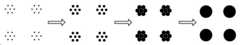
본 개시의 몇몇 구체예는 유리 또는 유리 세라믹 패널 내의 마이크로-퍼포레이션 형성 방법으로서: (i) 레이저 빔에 의해 손상 트랙의 서브셋(subset)을 상기 유리 또는 유리 세라믹 패널로 형성하는 단계, 여기서 손상 트랙은 패턴을 형성하기 위해 위치되며; (ii) 레이저 빔에 의해 복수의 손상 트랙을 상기 유리 또는 유리 세라믹 패널로 형성하는 단계, 여기서 상기 패널은 평면 내에서 연장하고 소정의 두께를 가지며, 여기서 상기 손상 트랙은 제1 직경을 갖고; 및 (iii) 손상 트랙의 상기 서브셋이 제2 직경을 갖는 마이크로-퍼포레이션을 갖는 마이크로-퍼포레이팅된 패널을 형성하기 위해 합병하도록 (ii)로부터 얻어진 상기 패널을 산 용액 내에서 에칭하는 단계를 포함하는 유리 또는 유리 세라믹 패널 내의 마이크로-퍼포레이션 형성 방법에 관한 것이며, 여기서 상기 마이크로-퍼포레이팅된 패널의 NRC는 약 0.3 내지 1이다.Some embodiments of the present disclosure provide a method of forming a micro-perforation in a glass or glass ceramic panel, comprising the steps of: (i) forming a subset of damaged tracks with a laser beam into the glass or glass ceramic panel, Are positioned to form a pattern; (ii) forming a plurality of damaged tracks by the laser beam into the glass or glass ceramic panel, wherein the panel extends in a plane and has a predetermined thickness, wherein the damaged track has a first diameter; And (iii) etching said panel obtained in (ii) in an acid solution such that said subset of damage tracks merge to form a micro-perforated panel having micro-perforations having a second diameter Perforated in a glass or glass ceramic panel wherein the NRC of the micro-perforated panel is about 0.3 to 1.
본 개시의 몇몇 구체예는 유리 또는 유리 세라믹 패널 내의 마이크로-퍼포레이션 형성 방법으로서: (i) 레이저 빔에 의해 손상 트랙의 서브셋을 상기 유리 또는 유리 세라믹 패널로 형성하는 단계, 여기서 상기 손상 트랙은 지엽적인(peripheral) 패턴을 형성하기 위해 위치되며; (ii) 레이저 빔에 의해 복수의 손상 트랙을 상기 유리 또는 유리 세라믹 패널로 형성하는 단계, 여기서 상기 패널은 평면 내에서 연장하고 소정의 두께를 가지며, 여기서 상기 손상 트랙은 제1 직경을 갖고; 및 (iii) 손상 트랙의 상기 서브셋이 상기 패널의 일 섹션을 제거하고 제2 직경을 갖는 마이크로-퍼포레이션을 갖는 마이크로-퍼포레이팅된 패널을 형성하기 위해 합병하도록 (ii)로부터 얻어진 상기 패널을 산 용액 내에서 에칭하는 단계를 포함하는 유리 또는 유리 세라믹 패널 내의 마이크로-퍼포레이션 형성 방법에 관한 것이며, 여기서 상기 마이크로-퍼포레이팅된 패널의 NRC는 약 0.3 내지 1이다.Some embodiments of the present disclosure are directed to a method of forming a micro-perforation in a glass or glass ceramic panel, the method comprising: (i) forming a subset of damaged tracks with the laser beam into the glass or glass ceramic panel, Is positioned to form a peripheral pattern; (ii) forming a plurality of damaged tracks by the laser beam into the glass or glass ceramic panel, wherein the panel extends in a plane and has a predetermined thickness, wherein the damaged track has a first diameter; And (iii) assembling said panel obtained from (ii) to merge said subset of damage tracks to form a micro-perforated panel having a micro-perforation with a second diameter and removing a section of said panel. Wherein the NRC of the micro-perforated panel is from about 0.3 to about 1.
몇몇 구체예에서, 상기 레이저 빔은 빔 전파 방향을 따라 지향되는 초점 라인을 가지며 상기 레이저 빔 초점 라인을 상기 패널 내로 향하게 하는 펄스 레이저 빔이며, 여기서 상기 빔 초점 라인은 복수의 손상 트랙의 형성을 위한 패널과 실질적으로 수직이다.In some embodiments, the laser beam is a pulsed laser beam having a focal line oriented along a beam propagation direction and directing the laser beam focal line into the panel, wherein the beam focal line is for generating a plurality of damaged tracks Is substantially perpendicular to the panel.
몇몇 구체예에서, 인접한 손상 트랙 사이의 간격은 원하는 퍼포레이션 형상 또는 크기를 얻기 위해 조정된다. 몇몇 구체예에서, 상기 레이저 빔은 펄스 레이저 빔이며, 상기 펄스 레이저 빔은 상기 패널 상의 소정의 위치를 1회 이상 때리도록 배열된다.In some embodiments, the spacing between adjacent damaged tracks is adjusted to obtain the desired perforation shape or size. In some embodiments, the laser beam is a pulsed laser beam, and the pulse laser beam is arranged to strike at least a predetermined position on the panel.
본 개시의 몇몇 구체예는 소리를 감쇠(dampen)시키는 방법으로서: 일반적으로 제1 패널 또는 제2 패널에 평행인 고체 뒷벽이 상기 제1 및 제2 패널의 12 인치 이내에 없도록 제1 및 제2 유리 또는 유리 세라믹 패널을 포함하는 제품을 위치시키는 단계를 포함하는 소리를 감쇠시키는 방법에 관한 것이다. 상기 제1 및 제2 유리 또는 유리 세라믹 패널 각각은: 평면 내에서 연장하고; 소정의 두께를 포함하며; 및 소정의 직경을 갖는 복수의 마이크로-퍼포레이션을 포함한다. 여기서 상기 패널의 두께 대 상기 마이크로-퍼포레이션의 직경의 비는 25 미만, 또는 약 0.1 내지 20이다.Some embodiments of the present disclosure provide a method of dampening sound comprising: providing a first and a second glass such that a solid back wall, which is generally parallel to the first panel or the second panel, is not within 12 inches of the first and second panels; Or placing a product comprising a glass ceramic panel. Each of said first and second glass or glass ceramic panels extending in a plane; Includes a predetermined thickness; And a plurality of micro-perforations having a predetermined diameter. Wherein the ratio of the thickness of the panel to the diameter of the micro-perforations is less than 25, or about 0.1 to 20.
본 개시는 수반된 도면과 함께 다음의 상세한 설명에 의해 쉽게 이해될 것이며, 여기서 동일한 참조 번호는 동일한 구조적 요소를 나타내며:
도 1a는 일 구체예에 따른 제품을 도시한다.
도 1b는 도 1a에 도시된 제품 내의 마이크로-퍼포레이션의 확대도를 도시한다.
도 1c는 일 구체예에 따라 배치된 뒷벽을 갖는 도 1a에 도시된 제품의 측면도를 도시한다.
도 1d는 일 구체예에 따른 제품의 측면도를 도시한다.
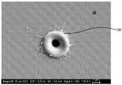
도 2a는 일 구체예에 따른 마이크로-퍼포레이션의 부분 확대도를 도시한다.
도 2b는 일 구체예에 따른 마이크로-퍼포레이션의 단면도를 도시한다.
도 3a는 일 구체예에 따른 마이크로-퍼포레이션의 단면도를 도시한다.
도 3b는 일 구체예에 따른 마이크로-퍼포레이션의 단면도를 도시한다.
도 4a는 일 구체예에 따른 단일 마이크로-퍼포레이팅된 패널(10 mm 캐비티(cavity) 간격)의 다양한 주파수에 걸친 대표적인 흡음율을 나타낸다.
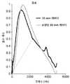
도 4b는 일 구체예에 따른 단일 마이크로-퍼포레이팅된 패널(35 mm 캐비티 간격)의 다양한 주파수에 걸친 대표적인 흡음율을 나타낸다.
도 5a는 일 구체예에 따른 두 겹(double leaf)의 마이크로-퍼포레이팅된 패널(각각 10 mm 및 14 mm 캐비티 간격)의 다양한 주파수에 걸친 대표적인 흡음율을 나타낸다.
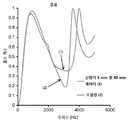
도 5b는 일 구체예에 따른 두 겹의 마이크로-퍼포레이팅된 패널(각각 5 mm 및 50 mm 캐비티 간격)의 다양한 주파수에 걸친 대표적인 흡음율을 나타낸다.
도 6은 일 구체예에 따른 단일 마이크로-퍼포레이팅된 패널 및 두 겹의 마이크로-퍼포레이팅 배치 모두의 다양한 주파수에 걸친 대표적인 흡음율을 나타낸다.
도 7은 일 구체예에 따른 레이저 시스템의 개략도를 도시한다.
도 8은 일 구체예에 따른 대표적인 레이저 버스트(burst) 패턴을 도시한다.
도 9는 일 구체예에 따른 마이크로-퍼포레이팅된 패널의 대표적인 형성 방법의 개략도를 도시한다.
도 10은 일 구체예에 따른 마이크로-퍼포레이션의 부분 확대도를 도시한다.
도 11은 일 구체예에 따른 마이크로-퍼포레이션의 단면도를 도시한다.
도 12는 일 구체예에 따른 마이크로-퍼포레이팅된 패널의 대표적인 형성 방법의 개략도를 도시한다.
도 13은 일 구체예에 따른 마이크로-퍼포레이팅된 패널의 대표적인 형성 방법의 개략도를 도시한다.
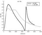
도 14는 일 구체예에 따른 다양한 마이크로-퍼포레이션 직경(각각 200 ㎛, 500 ㎛, 및 200 ㎛과 500 ㎛ 모두)을 갖는 마이크로-퍼포레이팅된 패널 배치의 다양한 주파수에 걸친 대표적인 흡음율을 나타낸다.
도 15는 비-마이크로-퍼포레이팅된 유리 패널을 갖는 일 구체예에 따른 2개의 마이크로-퍼포레이팅된 유리 패널의 강도를 비교한다.
도 16은 일 구체예에 따른 다중-패널 구조물을 도시한다.
도 17은 일 구체예에 따른 뒷벽 근처에 위치된 다중-패널 구조물을 도시한다.
도 18은 일 구체예에 따른 뒷벽 근처에 위치된 다중-패널 구조물을 도시한다.
도 19는 뒷벽이 있는 다중-패널 구조물 및 뒷벽이 없는 다중-패널 구조물의 모델링된 음향 성능을 나타낸다.
도 20은 뒷벽이 없는 다중-패널 구조물에 대한 모델링된 흡음율 대 주파수의 그래프를 도시한다.
도 21은 일 구체예에 따른 정렬되지 않은 홀(hole)을 갖는 이중 패널 구조물(2100)을 도시한다.
도 22는 정렬된 홀을 갖는 이중 패널 구조물(220)을 도시한다.
도 23은 다중-패널 구조물 내 상이한 패널 사이의 홀의 정렬 대 정렬 불량(misalignment)의 효과를 나타내는 흡음 프로파일을 도시한다.
도 24는 미스매치된(mismatched) 홀 크기를 갖는 이중 패널 구조물(2400)을 도시한다.
도 25는 다중-패널 구조물 내 상이한 패널의 홀 사이의 미스매치된 홀 크기의 효과를 나타내는 흡음 프로파일을 도시한다.
도 26은 다양한 내부-패널 갭에 대한, 뒷벽이 없는 이중 패널 구조물에 대한 흡음 프로파일을 도시한다.
도 27은 모래시계 홀 기하 구조 및 원통형 홀 기하 구조를 도시한다.
도 28은 모래시계 홀 기하 구조 및 원통형 홀 기하 구조에 대한 흡음 프로파일을 도시한다.
도 29는 동일한 이중 패널 구조물에 대한 모델링된 흡수 프로파일 대 측정된 흡수 프로파일의 비교를 도시한다.
도 30은 템퍼링된(tempered) 유리 또는 유리 세라믹의 예를 도시한다.The present disclosure will be readily understood by the following detailed description in conjunction with the accompanying drawings, in which like reference numerals designate like structural elements,
1A shows an article according to one embodiment.
Figure 1B shows an enlarged view of the micro-perforations in the product shown in Figure 1A.
1C shows a side view of the product shown in FIG. 1A having a rear wall disposed according to one embodiment.
Figure 1D shows a side view of an article according to one embodiment.
Figure 2a shows a partial enlarged view of a micro-perforation in accordance with one embodiment.
Figure 2B shows a cross-sectional view of a micro-perforation according to one embodiment.
3A shows a cross-sectional view of a micro-perforation according to one embodiment.
Figure 3B shows a cross-sectional view of a micro-perforation according to one embodiment.
4A shows a representative sound absorption rate over various frequencies of a single micro-perforated panel (10 mm cavity spacing) according to one embodiment.
4B shows a representative sound absorption rate over various frequencies of a single micro-perforated panel (35 mm cavity spacing) according to one embodiment.
Figure 5a shows a representative sound absorption rate over various frequencies of a double leaf micro-perforated panel (10 mm and 14 mm cavity spacing, respectively) according to one embodiment.
Figure 5b shows a representative sound absorption rate over various frequencies of a two-layer micro-perforated panel (5 mm and 50 mm cavity spacing, respectively) according to one embodiment.
Figure 6 shows a representative sound absorption rate over various frequencies for both a single micro-perforated panel and a two-layer micro-perforated arrangement, according to one embodiment.
Figure 7 shows a schematic diagram of a laser system according to one embodiment.
Figure 8 illustrates an exemplary laser burst pattern according to one embodiment.
Figure 9 shows a schematic view of an exemplary method of forming a micro-perforated panel according to one embodiment.
Figure 10 shows a partial enlarged view of a micro-perforation in accordance with one embodiment.
11 illustrates a cross-sectional view of a micro-perforation in accordance with one embodiment.
Figure 12 shows a schematic view of an exemplary method of forming a micro-perforated panel according to one embodiment.
Figure 13 shows a schematic view of an exemplary method of forming a micro-perforated panel according to one embodiment.
Figure 14 shows representative absorption rates over various frequencies of a micro-perforated panel arrangement with various micro-perforation diameters (200 占 퐉, 500 占 퐉, and 200 占 퐉 and 500 占 퐉, respectively) according to one embodiment.
Figure 15 compares the intensities of two micro-perforated glass panels according to one embodiment with a non-micro-perforated glass panel.
16 illustrates a multi-panel structure according to one embodiment.
Figure 17 illustrates a multi-panel structure positioned near a rear wall according to one embodiment.
18 illustrates a multi-panel structure positioned near a rear wall according to one embodiment.
Figure 19 shows the modeled acoustic performance of a multi-panel structure with a back wall and a multi-panel structure without a back wall.
Figure 20 shows a graph of modeled absorption versus frequency for a multi-panel structure without a back wall.
Figure 21 illustrates a dual panel structure 2100 with unaligned holes according to one embodiment.
Figure 22 shows a dual panel structure 220 with aligned holes.
Figure 23 shows a sound absorption profile showing the effect of misalignment versus alignment of holes between different panels in a multi-panel structure.
FIG. 24 shows a
Figure 25 shows a sound absorption profile showing the effect of mismatched hole sizes between holes of different panels in a multi-panel structure.
Figure 26 shows the sound absorption profile for a dual panel structure without back wall, for various interior-panel gaps.
Figure 27 shows an hourglass hole geometry and a cylindrical hole geometry.
Figure 28 shows the sound absorption profile for an hourglass hole geometry and a cylindrical hole geometry.
Figure 29 shows a comparison of a modeled absorption profile versus a measured absorption profile for the same dual panel structure.
30 shows an example of a tempered glass or glass ceramic.
본 발명(들)은 이제 수반된 도면에 설명된 바와 같은 이들의 구체예를 참조하여 상세히 기술될 것이다. "일 구체예", "구체예", "예시적인 구체예" 등에 대한 언급은 기술된 구체예가 특정 특징, 구조, 또는 특성을 포함할 수 있으나, 모든 구체예가 반드시 특정 특징, 구조, 또는 특성을 포함할 수 있는 것은 아님을 나타낸다. 또한, 이러한 문구는 반드시 동일한 구체예를 언급하는 것은 아니다. 또한, 특정 특징, 구조, 또는 특성이 구체예와 관련하여 기술될 때, 명시적으로 기술되는지 여부와 관계 없이 다른 구체예와 관련하여 이러한 특징, 구조, 또는 특성에 영향을 미치는 것은 본 기술 분야의 기술자의 지식 범위 내이다.The invention (s) will now be described in detail with reference to specific embodiments thereof as illustrated in the accompanying drawings. Reference to "an embodiment," "an embodiment," "an embodiment," "an embodiment," "an embodiment," "an embodiment," "an embodiment," "an embodiment," " Indicates that it can not be included. Also, these phrases do not necessarily refer to the same embodiment. Also, when a particular feature, structure, or characteristic is described in connection with the embodiment, whether affecting such feature, structure, or characteristic in relation to other embodiments, whether explicitly described or not, It is within the knowledge of the technician.
본 발명(들)은 도면을 참조하여 아래에 기술된다. 그러나, 본 기술 분야의 기술자는 이들 도면과 관련하여 본원에 주어진 상세한 설명이 단지 설명의 목적이며 제한을 위한 것으로 해석되어서는 안됨을 쉽게 알 수 있을 것이다. 본원에 사용된 바와 같이, 범위는 끝점(end point)을 포함하며, "~부터(from)", "사이에(between)", "~까지(to)", "및(and)" 뿐 아니라 다른 관련된 용어는 범위의 끝점을 포함한다. 본원에 사용된 바와 같이, "대략" 또는 "약"은 열거된 값의 10% 이내를 포함하는 의미로 간주될 수 있다.The invention (s) are described below with reference to the drawings. It will be apparent, however, to one skilled in the art that the detailed description given herein with respect to these drawings is for purposes of illustration only and is not to be construed as limiting. As used herein, a range includes an end point and includes not only "from", "between", "to", "and" Other related terms include the end point of the range. As used herein, "about" or "about" can be considered to mean within 10% of the listed values.
본원에 사용된 바와 같이, 용어 "마이크로-퍼포레이션"은 원형 및/또는 비-원형의 마이크로-홀을 포함할 수 있다. 용어 "비-원형"은 원형이 아닌 임의의 형상을 포함할 수 있다. 용어 "직경"은 마이크로-퍼포레이션의 중심을 통과하는 점에서 마이크로-퍼포레이션의 개구를 가로지르는 최소 거리를 의미하는 것으로 간주될 수 있으며, 여기서 중심 및 직경은 마이크로-퍼포레이션이 존재하는 패널의 표면 상의 마이크로-퍼포레이션의 면적에 기초한다. 예를 들어, 마이크로-퍼포레이션이 실질적으로 원통형인 경우, 직경은 개구를 정의하는 원의 중심을 가로지르는 거리이다. 또한, 도 10 및 도 11에 도시된 바와 같이, 마이크로-퍼포레이션의 개구는 마이크로-퍼포레이션이 원통형이 아니도록 비-원형일 수 있다. 이들 경우에, "직경"은 중심을 통과하는 마이크로-퍼포레이션의 비-원형 개구를 가로지르는 최소 거리를 의미하는 것으로 간주될 수 있다. 용어 "홀" 및 "마이크로퍼포레이션"은 상호 교환적으로 사용된다.As used herein, the term "micro-perforations" may include circular and / or non-circular micro-holes. The term "non-circular" may include any shape that is not circular. The term "diameter" can be considered to mean the minimum distance across the opening of the micro-perforations at the point through the center of the micro-perforations, where the center and the diameter Is based on the area of the micro-perforations on the surface. For example, if the micro-perforations are substantially cylindrical, the diameter is the distance across the center of the circle defining the opening. Also, as shown in Figures 10 and 11, the opening of the micro-perforations may be non-circular such that the micro-perforations are not cylindrical. In these cases, "diameter" can be considered to mean the minimum distance across the non-circular opening of the micro-perforations passing through the center. The terms "hole" and "microperforation" are used interchangeably.
본원에 사용된 바와 같이, "일반적으로 평행한" 평면은 10 도 이하의 각을 형성하는 표면 법선을 갖는 2개의 평면을 의미한다.As used herein, a "generally parallel" plane refers to two planes having a surface normal that forms an angle of 10 degrees or less.
실내 음향을 다루는 것은 이것이 음향 과학 및 원리 외에도 건축 설계 및 엔지니어링을 모두 포함하기 때문에 어렵다. 마이크로-퍼포레이팅된 패널은 일반적으로 헬름홀츠(Helmholtz) 공명 원리에 기초한 공명 흡음 시스템을 형성할 수 있다.Dealing with room acoustics is difficult because it involves both architectural design and engineering in addition to acoustic science and principles. The micro-perforated panel can generally form a resonant sound-absorbing system based on the Helmholtz resonance principle.
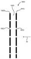
도 1a 및 1b에 도시된 바와 같이, 예를 들어, 본 개시의 몇몇 구체예는 소정의 두께를 갖는 유리 또는 유리 세라믹 패널(10)을 포함하는 제품에 관한 것이며, 여기서 상기 패널은 소정의 두께를 갖는 복수의 마이크로-퍼포레이션(100)을 가지며; 및 여기서 패널(10)의 두께 대 마이크로-퍼포레이션(100)의 직경의 비는 25 미만, 또는 20 미만이다. 몇몇 구체예에서, 패널(10)의 두께 대 마이크로-퍼포레이션(100)의 직경의 비는 약 0.1 내지 20, 약 1 내지 20, 약 1 내지 15, 약 1 내지 10, 약 1 내지 5, 약 5 내지 20, 약 5 내지 15, 약 5 내지 10, 약 10 내지 20, 또는 약 10 내지 15, 또는 약 1, 2, 3, 4, 5, 6, 7, 8, 9, 10, 11, 12, 13, 14, 15, 16, 17, 18, 19, 20, 21, 22, 23, 24, 25, 또는 이들 값 중 임의의 2개를 끝점으로서 갖는 임의의 범위이다. 몇몇 구체예에서, 패널의 두께 대 마이크로-퍼포레이션의 직경의 비는 약 2 내지 8, 또는 약 3 내지 6이다.As shown in FIGS. 1A and 1B, for example, some embodiments of the present disclosure are directed to a product comprising a glass or glass
몇몇 구체예에서, 상기 두께는 약 0.05 mm 내지 6 mm, 약 0.05 mm 내지 3 mm, 약 0.05 mm 내지 2 mm, 약 0.1 mm 내지 3 mm, 약 0.1 mm 내지 2 mm, 약 0.1 mm 내지 약 1 mm, 약 0.1 mm 내지 0.6 mm이다. 몇몇 구체예에서, 상기 두께는 0.05 mm, 0.1 mm, 0.5 mm, 0.6 mm, 0.7 mm, 0.8 mm, 0.9 mm, 1 mm, 2 mm, 3 mm, 4 mm, 5 mm, 6 mm, 또는 이들 값 중 임의의 2개를 끝점으로서 갖는 임의의 범위일 수 있다. 예를 들어, 상기 두께는 약 0.05 mm 내지 약 6 mm, 약 0.05 mm 내지 약 5 mm, 약 0.05 mm 내지 약 4 mm, 약 0.05 mm 내지 약 3.5 mm, 약 0.05 mm 내지 약 3 mm, 약 0.05 mm 내지 약 2.5 mm, 약 0.05 mm 내지 약 2 mm, 약 0.05 mm 내지 약 1.5 mm, 약 0.05 mm 내지 약 1.2 mm, 약 0.05 mm 내지 약 1 mm, 약 0.1 mm 내지 약 6 mm, 약 0.2 mm 내지 약 6 mm, 약 0.3 mm 내지 약 6 mm, 약 0.4 mm 내지 약 6 mm, 약 0.5 mm 내지 약 6 mm, 약 0.55 mm 내지 약 6 mm, 약 0.7 mm 내지 약 6 mm, 약 0.8 mm 내지 약 6 mm, 약 0.9 mm 내지 약 6 mm, 약 1 mm 내지 약 6 mm, 약 1.1 mm 내지 약 6 mm, 약 1.2 mm 내지 약 6 mm, 약 1.5 mm 내지 약 6 mm, 약 2 mm 내지 약 6 mm, 약 2.5 mm 내지 약 6 mm, 약 3 mm 내지 약 6 mm, 약 0.1 mm 내지 약 1 mm, 약 0.3 mm 내지 약 1 mm, 약 0.4 mm 내지 약 1 mm, 약 0.5 mm 내지 약 1 mm, 또는 약 0.3 mm 내지 약 0.7 mm일 수 있다. 몇몇 구체예에서, 마이크로-퍼포레이션은 약 0.05 mm 내지 6 mm 이격(예를 들어, "피치(pitch)")될 수 있다. 비-균일 간격의 경우, 피치는 이들이 균일하게 분포되는 경우 마이크로-퍼포레이션 간 평균 거리로서 계산될 수 있다.In some embodiments, the thickness is from about 0.05 mm to about 6 mm, from about 0.05 mm to about 3 mm, from about 0.05 mm to about 2 mm, from about 0.1 mm to about 3 mm, from about 0.1 mm to about 2 mm, from about 0.1 mm to about 1 mm , About 0.1 mm to about 0.6 mm. In some embodiments, the thickness is selected from the group consisting of 0.05 mm, 0.1 mm, 0.5 mm, 0.6 mm, 0.7 mm, 0.8 mm, 0.9 mm, 1 mm, 2 mm, 3 mm, 4 mm, 5 mm, 6 mm, ≪ / RTI > may have any range with any two of them as end points. For example, the thickness may range from about 0.05 mm to about 6 mm, from about 0.05 mm to about 5 mm, from about 0.05 mm to about 4 mm, from about 0.05 mm to about 3.5 mm, from about 0.05 mm to about 3 mm, From about 0.05 mm to about 2 mm, from about 0.05 mm to about 1.5 mm, from about 0.05 mm to about 1.2 mm, from about 0.05 mm to about 1 mm, from about 0.1 mm to about 6 mm, from about 0.2 mm to about 2.5 mm From about 0.5 mm to about 6 mm, from about 0.7 mm to about 6 mm, from about 0.8 mm to about 6 mm, from about 0.3 mm to about 6 mm, from about 0.3 mm to about 6 mm, from about 0.4 mm to about 6 mm, From about 0.9 mm to about 6 mm, from about 1 mm to about 6 mm, from about 1.1 mm to about 6 mm, from about 1.2 mm to about 6 mm, from about 1.5 mm to about 6 mm, from about 2 mm to about 6 mm, From about 0.3 mm to about 1 mm, from about 0.4 mm to about 1 mm, from about 0.5 mm to about 1 mm, or from about 0.3 mm to about 6 mm, from about 3 mm to about 6 mm, from about 0.1 mm to about 1 mm, mm to about 0.7 mm. In some embodiments, the micro-perforations may be spaced from about 0.05 mm to 6 mm (e.g., "pitch"). For non-uniform spacing, the pitch can be calculated as the average distance between micro-perforations if they are uniformly distributed.
몇몇 구체예에서, 마이크로-퍼포레이션은 패널의 두께를 통한 일반적으로 원형 단면을 갖는다. 몇몇 구체예에서, 마이크로-퍼포레이션은 패널의 두께를 통한 비-원형 단면을 갖는다. 몇몇 구체예에서, 패널의 단면을 통한 마이크로-퍼포레이션의 형상은 변화하거나, 실질적으로 일정하다.In some embodiments, the micro-perforations have a generally circular cross-section through the thickness of the panel. In some embodiments, the micro-perforations have a non-circular cross-section through the thickness of the panel. In some embodiments, the shape of the micro-perforations through the cross-section of the panel is varied or substantially constant.
몇몇 구체예에서, 상기 직경은 약 0.02 mm 내지 5 mm, 약 0.05 mm 내지 2 mm, 약 0.1 mm 내지 2 mm, 약 0.1 mm 내지 약 1 mm, 약 0.1 mm 내지 0.6 mm이다.In some embodiments, the diameter is from about 0.02 mm to about 5 mm, from about 0.05 mm to about 2 mm, from about 0.1 mm to about 2 mm, from about 0.1 mm to about 1 mm, from about 0.1 mm to about 0.6 mm.
몇몇 구체예에서, 패널은 동작 가능 환경의 잔향 시간을 감소시키도록 배열된다. 본원에 사용된 바와 같이, "작동 가능 환경"은 특정 음향 환경을 요구하는 폐쇄 또는 반-폐쇄된 환경을 포함할 수 있다. 예를 들어, 회의실, 사무실, 학교, 병원, 제조 시설, 청정실(식품, 제약), 박물관, 역사적인 건물, 레스토랑 등은 모두 "작동 가능 환경"일 수 있다. 몇몇 구체예에서, 패널은 조명 솔루션, 예를 들어 천장 또는 벽의 조명 설비에 통합된다. 이와 관련하여, 패널의 투명한 특성은 패널의 노이즈 감소 특성의 이점을 취하면서 광을 허용하는데 사용된다. 패널 뒤의 자연 에어 간격(조명 설비 내)은 또한 소음 감소 관점에서 유리할 수 있다.In some embodiments, the panel is arranged to reduce the reverberation time of the operable environment. As used herein, "operational environment" may include a closed or semi-closed environment requiring a particular acoustic environment. For example, conference rooms, offices, schools, hospitals, manufacturing facilities, clean rooms (food and pharmaceuticals), museums, historic buildings, restaurants and the like can all be "operational environments". In some embodiments, the panel is integrated into a lighting solution, for example a ceiling or wall lighting fixture. In this regard, the transparent properties of the panel are used to allow light while taking advantage of the panel's noise reduction characteristics. The natural air gap behind the panel (in the lighting fixture) can also be advantageous from a noise reduction standpoint.
몇몇 구체예에서, 상기 패널은 강화된 유리 또는 유리 세라믹을 포함한다. 유리 또는 유리 세라믹 물질의 사용은 투명, 반투명 또는 불투명 외관의 제공, 내구성의 제공, 내부식성의 제공, 설계 유연성의 제공, 및 내염성의 제공 중 임의의 하나 또는 이들의 조합을 포함하는 유리한 특성을 허용한다.In some embodiments, the panel comprises reinforced glass or glass ceramic. The use of glass or glass ceramic materials permits advantageous properties including the provision of a transparent, translucent or opaque appearance, the provision of durability, the provision of corrosion resistance, the provision of design flexibility, and the provision of salt resistance, or any combination thereof do.
몇몇 구체예에서, 강화된 유리의 경우, 표면 압축은 유리 내부의 인장 응력 영역에 의해 균형을 이룬다. 400 MPa 초과, 500 MPa 초과, 600 MPa 초과, 700 MPa 초과, 또는 750 MPa 초과의 표면 압축 응력("CS") 및 40 미크론 초과의 압축 응력 층 깊이(압축 깊이, 또는 "DOC"라고도 함)는 화학적 강화 공정(예를 들어, 이온 교환 공정)에 의해 몇몇 유리, 예를 들어, 알칼리 알루미노실리케이트 유리 내에서 쉽게 달성된다. DOC는 응력이 압축성으로부터 인장성으로 변화하는 깊이를 나타낸다.In some embodiments, in the case of reinforced glass, the surface compression is balanced by the tensile stress region within the glass. A surface compressive stress ("CS") of greater than 400 MPa, greater than 500 MPa, greater than 600 MPa, greater than 700 MPa, or greater than 750 MPa, and a compressive stress layer depth greater than 40 microns (also referred to as "compression depth" or "DOC" For example, alkali aluminosilicate glass by chemical strengthening processes (e.g., ion exchange processes). DOC represents the depth at which the stress changes from compressive to tensile.
몇몇 구체예에서, 상기 패널은 비-강화된 유리, 예를 들어, 소다-석회 유리를 포함한다. 몇몇 구체예에서, 상기 패널은 기계적으로, 열적으로 또는 화학적으로 강화된 강화된 유리 또는 유리 세라믹을 포함한다. 몇몇 구체예에서, 강화된 유리 또는 유리 세라믹은 기계적 및 열적으로 강화되거나, 기계적 및 화학적으로 강화되거나 열적 및 화학적으로 강화될 수 있다. 기계적으로-강화된 유리 또는 유리 세라믹은 유리 또는 유리 세라믹의 부분 사이의 열 팽창 계수의 미스매치에 의해 생성된 압축 응력 층(및 대응하는 인장 응력 영역)을 포함할 수 있다. 화학적으로-강화된 유리 또는 유리 세라믹은 압축 응력 층(및 이온 교환 공정에 의해 생성된 대응하는 인장 응력 영역)을 포함할 수 있다. 이러한 화학적으로 강화된 유리 및 유리 세라믹에서, 유리 네트워크가 이완될 수 있는 온도 미만의 온도에서의 보다 작은 이온의 보다 큰 이온에 의한 대체는 응력 프로파일을 생성하는 유리의 표면에 걸친 이온의 분포를 생성한다. 들어오는 이온의 보다 큰 부피는 기판의 표면 부분 상에 CS를 생성하고 유리 또는 유리 세라믹의 중심에 장력을 생성한다. 열적으로-강화된 유리 또는 유리 세라믹에서, CS 영역은 유리 또는 유리 세라믹을 유리 전이 온도 초과, 유리 연화점 근처의 상승된 온도로 가열한 후, 표면 영역을 유리 또는 유리 세라믹의 내부 영역보다 빠르게 냉각함에 의해 형성된다. 표면 영역과 내부 영역 사이의 상이한 냉각 속도는 잔류 표면 CS를 생성하며, 이는 차례로 중심 영역 내의 대응하는 인장 응력을 생성한다. 일 이상의 구체예에서, 유리 기판은 어닐링되거나 열 강화된 소다 석회 유리를 배제한다. 일 이상의 구체예에서, 유리 기판은 어닐링되거나 열 강화된 소다 석회 유리를 포함한다.In some embodiments, the panel comprises a non-reinforced glass, e.g., soda-lime glass. In some embodiments, the panel comprises a reinforced glass or glass ceramic mechanically, thermally or chemically reinforced. In some embodiments, the reinforced glass or glass ceramic may be mechanically and thermally reinforced, mechanically and chemically reinforced, or thermally and chemically reinforced. Mechanically-enhanced glass or glass ceramics may comprise a compressive stress layer (and corresponding tensile stress region) created by mismatching the coefficient of thermal expansion between portions of the glass or glass ceramic. The chemically-enhanced glass or glass ceramic may comprise a compressive stress layer (and corresponding tensile stress regions produced by an ion exchange process). In these chemically reinforced glasses and glass ceramics, the substitution of smaller ions with larger ions at temperatures below the temperature at which the glass network can relax creates a distribution of ions across the surface of the glass producing a stress profile do. The larger volume of incoming ions creates CS on the surface portion of the substrate and creates tension in the center of the glass or glass ceramic. In thermally-enhanced glass or glass ceramics, the CS region is formed by heating the glass or glass ceramic above the glass transition temperature, at an elevated temperature near the glass softening point, and then cooling the surface region faster than the inner region of the glass or glass ceramic . The different cooling rates between the surface area and the inner area produce a residual surface CS which, in turn, produces a corresponding tensile stress in the center area. In one or more embodiments, the glass substrate excludes annealed or heat strengthened soda lime glass. In one or more embodiments, the glass substrate comprises an annealed or thermally enhanced soda lime glass.
몇몇 구체예에서, 유리 또는 유리 세라믹은 약 100 MPa 내지 약 1000 MPa, 약 100 MPa 내지 약 800 MPa, 약 100 MPa 내지 약 500 MPa, 약 100 MPa 내지 약 300 MPa, 또는 약 100 MPa 내지 약 150 MPa의 표면 압축 응력을 가질 수 있다. 몇몇 구체예에서, DOC는 0.05*t 내지 약 0.21*t(여기서 t는 마이크로미터 단위의 유리 또는 유리 세라믹의 두께임)일 수 있다. 몇몇 구체예에서, DOC는 약 0.05*t 내지 약 0.2*t, 약 0.05*t 내지 약 0.18*t, 약 0.05*t 내지 약 0.16*t, 약 0.05*t 내지 약 0.15*t, 약 0.05*t 내지 약 0.12*t, 약 0.05*t 내지 약 0.1*t, 약 0.075*t 내지 약 0.21*t, 약 0.1*t 내지 약 0.21*t, 약 0.12*t 내지 약 0.21*t, 약 0.15*t 내지 약 0.21*t, 약 0.18*t 내지 약 0.21*t, 또는 약 0.1*t 내지 약 0.18*t 범위 내일 수 있다.In some embodiments, the glass or glass ceramic has a thickness of from about 100 MPa to about 1000 MPa, from about 100 MPa to about 800 MPa, from about 100 MPa to about 500 MPa, from about 100 MPa to about 300 MPa, Lt; RTI ID = 0.0 > compressive < / RTI > In some embodiments, the DOC may be from 0.05 * t to about 0.21 * t, where t is the thickness of the glass or glass ceramic in micrometers. In some embodiments, the DOC is from about 0.05 * t to about 0.2 * t, from about 0.05 * t to about 0.18 * t, from about 0.05 * t to about 0.16 * t, from about 0.05 * t to about 0.15 * t to about 0.12 t, about 0.05 t to about 0.1 t, about 0.075 t to about 0.21 t, about 0.1 t to about 0.21 t, about 0.12 t to about 0.21 t, t to about 0.21 * t, from about 0.18 * t to about 0.21 * t, or from about 0.1 * t to about 0.18 * t.
강화되지 않은 유리 또는 유리 세라믹으로 제조된 소리 감쇠 패널을 사용하는 것은 안전 위험을 초래할 수 있다. 예를 들어, 패널이 손상되는 경우에 큰 파편으로 부서질 수 있다. 열 템퍼링은 이러한 안전 위험을 제거할 수 있으며, 이는 안전 특성 및 높은 음향 성능을 갖는 유리 또는 유리 세라믹 음향 패널의 개발을 야기한다. 현재, 템퍼링되는 유리 또는 유리 세라믹에 대한 최소한의 공지된 두께는 2 mm이다. 그러나, 유리 두께가 증가함에 따라, 패널의 음향 흡수 성능은 감소한다. 몇몇 구체예에서, 양호한 음향 성능은 다중 음향 패널을 사용하여 템퍼링된 유리 또는 유리 세라믹 내에서 달성된다. 다중 패널의 이러한 사용은 내부 건축 적용을 포함하는 다양한 분야에서 바람직할 수 있다. 용어 "템퍼링된", "열적으로 템퍼링된" 및 "열적으로 강화된" 및 이들의 변형은 동일한 효과를 의미한다.The use of sound attenuating panels made of ungardened glass or glass ceramics can pose a safety hazard. For example, if the panel is damaged, it can break into large pieces. Thermal tempering can eliminate this safety hazard, which leads to the development of glass or glass ceramic acoustic panels with safety characteristics and high acoustic performance. At present, the minimum known thickness for tempered glass or glass ceramics is 2 mm. However, as the glass thickness increases, the acoustic absorption performance of the panel decreases. In some embodiments, good acoustic performance is achieved in tempered glass or glass ceramics using a multi-acoustical panel. Such use of multiple panels may be desirable in a variety of applications, including interior architectural applications. The terms "tempered "," thermally tempered ", and "thermally enhanced"
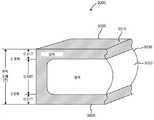
도 30은 템퍼링된 유리 또는 유리 세라믹의 예를 도시한다. 열 처리의 결과로서, 패널(3000)의 일부는 패널(3000)의 표면(3005)으로부터 압축 깊이(3030)까지 연장하는 압축의 영역(3010)을 갖는다. 패널(3000)의 물질은 표면 압축의 영역으로 지칭될 수 있는 영역(3010) 내에서 압축 상태이다. 인장 응력의 영역인 영역(3020)은 표면(3005)으로부터 압축 깊이(3030)보다 멀리 있는 패널(3000)의 일부이다. 도 30의 예에서, 압축 깊이는 패널(3000)의 두께의 0.21배이다. 결과적으로, 영역(3010)의 두께는 패널(3000)의 각 표면으로부터 연장하는 패널(3000)의 두께의 0.21배이다. 영역(3020)의 두께는 패널(3000)의 두께의 0.58배이다.Fig. 30 shows an example of tempered glass or glass ceramic. As a result of the thermal treatment, a portion of the
열 템퍼링은 홀이 패널 내에 형성되어 마이크로-퍼포레이팅된 패널을 생성한 후에 수행될 수 있다. 적절하게 템퍼링된, 유리 또는 유리 세라믹 패널은 ANSI 97.1에 명시된 바와 같이 파손 시 작은 조각으로 다이싱된다(dice). 템퍼링 공정은 AMG(Acoustic Management Glass) 유리 패널을 이들의 임계 온도(> 650 ℃)로 가열하는 단계 및 패널의 물질 내에서 원하는 응력 프로파일을 생성하기 위해 후속적으로 급속히 냉각하는 단계(예를 들어, 유리는 이후 수 초간 공기의 블라스트(blast)에 의해 급속하게 냉각됨)를 포함한다. 표면이 빠르게 냉각되고 벌크(내부) 물질이 보다 느리게 냉각되므로, 템퍼링 공정은 물질의 벌크 내에 인장 응력 및 표면 상에 압축 응력을 초래한다(도 30 참조). 응력 층의 깊이는 냉각 온도, 시간 등의 결과이다. 이 템퍼링 공정은 유리가 파손 시 작은 조각으로 파괴(또는 다이싱됨)을 보장하여 사용하기에 안전하게 만든다.Thermal tempering may be performed after holes are formed in the panel to create the micro-perforated panel. An appropriately tempered glass or glass ceramic panel is diced into pieces in the event of breakage, as specified in ANSI 97.1. The tempering process includes heating the Acoustic Management Glass (AMG) glass panels to their critical temperature (> 650 DEG C) and subsequently rapidly cooling them to produce the desired stress profile in the material of the panel (e.g., The glass is then rapidly cooled by blasting of air for a few seconds. As the surface is rapidly cooled and the bulk (internal) material is cooled more slowly, the tempering process causes tensile stresses in the bulk of the material and compressive stresses on the surface (see FIG. 30). The depth of the stress layer is the result of cooling temperature, time, and so on. This tempering process ensures that the glass breaks (or dices) into small pieces upon breakage, making it safe to use.
몇몇 구체예에서, 패널 또는 제품은 강화된 유리 기판을 포함한다. 몇몇 구체예에서, 패널 또는 제품은 유리의 특정한 다이싱 패턴을 가질 수 있다. 몇몇 구체예에서, 다이싱 패턴은 안전 유리의 패턴일 수 있다. 몇몇 구체예에서, 유리는 안전 위험이 감소되도록 최적의 파괴된 조각의 평균 크기 및 크기 분포, 날카로운 점의 평균 각 및 이들 평균 각 주위의 분포, 및/또는 푀괴 시 방출 거리를 갖도록 강화될 수 있다.In some embodiments, the panel or article comprises a reinforced glass substrate. In some embodiments, the panel or article may have a specific dicing pattern of glass. In some embodiments, the dicing pattern may be a pattern of a safety glass. In some embodiments, the glass can be reinforced to have an average size and size distribution of the optimal fractured pieces, an average angle of sharp points and a distribution around these average angles, and / or a breakout distance to minimize safety hazards .
몇몇 구체예에서, 패널은 약 0.3 내지 1, 또는 약 0.3 내지 0.8의 NRC를 갖는다. 몇몇 구체예에서, 패널은 250 Hz 내지 6000 Hz, 또는 250 Hz 내지 20,000 Hz의 미리 정해진 주파수에 걸친 미리 정해진 흡음 계수를 갖는다. 몇몇 구체예에서, 패널은 예를 들어 기계실 또는 HVAC 적용에서 특정 관심 주파수를 흡수하도록 "조정(tune)"될 수 있다. 몇몇 구체예에서, 패널은 0.3, 0.4, 0.5, 0.6, 0.7, 0.8, 0.9, 1.0, 또는 이들 값 중 임의의 2개를 끝점으로 갖는 임의의 범위의 NRC를 갖는다.In some embodiments, the panel has an NRC of about 0.3 to 1, or about 0.3 to 0.8. In some embodiments, the panel has a predetermined sound absorption coefficient over a predetermined frequency of 250 Hz to 6000 Hz, or 250 Hz to 20,000 Hz. In some embodiments, the panel may be "tuned" to absorb a particular frequency of interest, for example, in a machine room or HVAC application. In some embodiments, the panel has an arbitrary range of NRCs with 0.3, 0.4, 0.5, 0.6, 0.7, 0.8, 0.9, 1.0, or any two of these values as endpoints.
몇몇 구체예에서, 패널의 에지의 일부는 홀딩 부분에 밀봉된다. 몇몇 구체예에서, 에지의 어느 부분도 홀딩 부분에 밀봉되지 않는다. 몇몇 구체예에서, 제품은 패널에 작동 가능하게 연결된 뒷벽(20)(도 1c에 도시됨)을 더욱 포함한다. 본원에 사용된 바와 같이, "작동 가능하게 연결된"은 패널 및 뒷벽이 함께 작동하여 노이즈 저감을 증가시키도록 직접 연결 또는 간접 연결, 또는 음향 연결을 포함할 수 있다. 몇몇 구체예에서, 뒷벽은 작동 가능 환경(예를 들어 방의 벽 또는 천장)에 존재하는, 실질적으로 강성인 구조물이다. 몇몇 구체예에서, 뒷벽은 음향 에코에 기여할 수도, 기여하지 않을 수도 있다. 유리하게는, 뒷벽은 마이크로-퍼포레이팅된 패널의 음향 성능을 변화시키지 않도록 강성 또는 단단한 표면일 수 있다. 몇몇 구체예에서, 패널은 예를 들어 설비를 사용하여 뒷벽의 앞에 매달리거나 뒷벽의 앞에 위치될 수 있다.In some embodiments, a portion of the edge of the panel is sealed to the holding portion. In some embodiments, no portion of the edge is sealed to the holding portion. In some embodiments, the product further includes a back wall 20 (shown in Figure 1C) operatively connected to the panel. As used herein, "operably connected" may include a direct or indirect connection, or an acoustic connection, such that the panel and the back wall operate together to increase noise reduction. In some embodiments, the back wall is a substantially rigid structure that is present in an operable environment (e.g., a wall or ceiling of a room). In some embodiments, the back wall may or may not contribute to the acoustic echo. Advantageously, the back wall can be a rigid or rigid surface so as not to alter the acoustic performance of the micro-perforated panel. In some embodiments, the panel may be hung in front of the back wall or in front of the back wall using, for example, equipment.
몇몇 구체예에서, 마이크로-퍼포레이션은 패널을 따라 균일한 간격으로 위치된다. 몇몇 구체예에서, 마이크로-퍼포레이션은 패널을 따라 균일한 밀도로 분포된다. 몇몇 구체예에서, 간격 또는 피치는 비-균일 간격일 수 있다. 몇몇 구체예에서, 마이크로-퍼포레이션은 비-균일 밀도로 분포된다. 몇몇 구체예에서, 비-균일 밀도 또는 간격은 예를 들어 광학적 왜곡을 감소시키거나, 장식 적용에 사용될 수 있다. 몇몇 구체예에서, 음향 성능은 특정 주파수에서의 소리 흡수를 최대화하기 위해 실질적으로 균일하게 되는 마이크로-퍼포레이션 사이의 평균 거리를 통해 제어될 수 있다. 몇몇 구체예에서, 피치는 예를 들어 보다 넓은 흡수 스펙트럼을 달성하기 위해 패널을 가로질러 변화될 수 있다. 몇몇 구체예에서, 마이크로-퍼포레이션은 예를 들어 로고, 텍스트, 꽃 패턴 등과 같은 다양한 적용을 찾을 수 있는 비-균일 밀도로 분포된다.In some embodiments, the micro-perforations are positioned at even intervals along the panel. In some embodiments, the micro-perforations are distributed at a uniform density along the panel. In some embodiments, the spacing or pitch may be non-uniform spacing. In some embodiments, the micro-perforations are distributed at a non-uniform density. In some embodiments, the non-uniform density or spacing can be used, for example, to reduce optical distortion, or to decorate. In some embodiments, acoustic performance can be controlled through an average distance between micro-perforations that becomes substantially uniform to maximize sound absorption at a particular frequency. In some embodiments, the pitch can be varied across the panel to achieve, for example, a wider absorption spectrum. In some embodiments, the micro-perforations are distributed at a non-uniform density to find various applications such as, for example, logos, text, floral patterns, and the like.
몇몇 구체예에서, 본 개시의 패널은 광색성(photochromic), 열 제어, 전기-변색성(electro-chromic), 저 방사율, UV 코팅, 눈부심-방지, 친수성, 소수성, 얼룩-방지, 지문-방지, 스크래치-방지, 반사-방지, 잉크-젯 장식, 스크린-프린팅, 깨짐-방지 등과 같은 코팅을 포함한다. 몇몇 구체예에서, 마이크로-퍼포레이션은 코팅에 의해 차단되지 않는다. 몇몇 구체예에서, 마이크로-퍼포레이션의 내부는 코팅되지 않는다. 몇몇 구체예에서, 마이크로-퍼포레이션의 일부는 코팅에 의해 차단된다. 몇몇 구체예에서, 패널은 항균 구성 요소를 포함한다.In some embodiments, the panels of the present disclosure can be used in various applications such as photochromic, thermal control, electro-chromic, low emissivity, UV coating, anti-glare, hydrophilic, hydrophobic, , Scratch-resistant, anti-reflective, ink-jet decorative, screen-printing, anti-cracking, and the like. In some embodiments, the micro-perforations are not blocked by the coating. In some embodiments, the interior of the micro-perforations is not coated. In some embodiments, a portion of the micro-perforations is blocked by the coating. In some embodiments, the panel comprises an antimicrobial component.
몇몇 구체예에서, 본 개시의 패널은 균일한 두께 또는 비-균일한 두께일 수 있다. 몇몇 구체예에서, 패널은 실질적으로 평면일 수 있다. 몇몇 구체예에서, 패널은 예를 들어 굽거나 복합 형상(complex shape)을 가질 수 있다. 몇몇 구체예에서, 패널은 예를 들어, 직사각형, 원형 등의 형상일 수 있다. 몇몇 구체예에서, 패널은 플렉서블(flexible)할 수 있다. 몇몇 구체예에서, 패널은 실질적으로 강성일 수 있다. 몇몇 구체예에서, 패널의 기하 구조 특성(예를 들어, 마이크로-퍼포레이션 직경, 마이크로-퍼포레이션 형상, 피치, 패널 두께 등) 및 패널의 흡수 계수는 원하는 실내 음향을 달성하도록 조정될 수 있다.In some embodiments, the panels of the present disclosure may be of uniform thickness or of a non-uniform thickness. In some embodiments, the panel may be substantially planar. In some embodiments, the panel may have, for example, a bake or a complex shape. In some embodiments, the panel can be, for example, in the shape of a rectangle, circle, or the like. In some embodiments, the panel may be flexible. In some embodiments, the panel can be substantially rigid. In some embodiments, the geometric characteristics (e.g., micro-perforation diameter, micro-perforation shape, pitch, panel thickness, etc.) of the panel and the absorption coefficient of the panel can be adjusted to achieve the desired room acoustics.
예를 들어, 실내에서의 잔향 시간(예를 들어, 에코)은 다음 식을 사용하여 실내에서의 물질의 흡수 계수에 반비례하며:For example, the reverberation time in the room (e. G., Echo) is inversely proportional to the absorption coefficient of the material in the room using:

여기서 V는 실내의 부피이고, S는 표면적이며 α는 물질의 흡수 계수이다. 잔향 시간은 환경에서 소리가 주어진 수준으로 감쇠되는데 걸리는 시간으로 정의될 수 있다. 보다 높은 잔향은 에코로 변환될 수 있다. 따라서, 종래의 유리는 거의 0의 소리 흡수를 갖기 때문에, 이는 긴 잔향 시간을 초래하고, 조음 명료도의 손실 및 불쾌한 음향 환경으로 이어진다. 반사를 최소화하고 양호한 흡수 특성을 달성하기 위해, 본 개시의 패널은 공기의 특성 임피던스 및 작은 음향 질량 리액턴스(mass reactance)(M)와 동일한 크기를 따른 음향 저항(R)을 달성하도록 배열될 수 있다. 최적의 음향 저항은 아래 식에 설명된 바와 같은 원하는 요건을 달성하기 위해 아래 기술된 제조 공정을 사용하여 마이크로 퍼포레이션을 제조함으로써 달성될 수 있으며:Where V is the volume of the room, S is the surface area and α is the absorption coefficient of the material. Reverberation time can be defined as the time it takes for the sound to attenuate to a given level in the environment. Higher reverberations can be converted to echoes. Thus, since conventional glasses have a sound absorption of almost zero, this results in a long reverberation time, resulting in loss of articulatory intelligibility and an unpleasant acoustic environment. To minimize reflection and achieve good absorption characteristics, the panel of the present disclosure can be arranged to achieve acoustic resistance R along the same magnitude as the characteristic impedance of air and the small acoustic mass reactance (M) . The optimal acoustic resistance can be achieved by fabricating the microperforations using the fabrication process described below to achieve the desired requirements as described in the following equation:

여기서 d는 홀/마이크로-퍼포레이션 직경이고, t는 패널의 두께이며, c는 공기 중의 소리의 속도, ρ는 공기 밀도, σ는 공극률, 및 η은 점도이다. 퍼포레이션 상수, k는 홀 직경 및 공기의 점도와 관련하여 정의될 수 있다:Where d is the hole / micro-perforation diameter, t is the thickness of the panel, c is the velocity of sound in air, p is air density, sigma is porosity, and eta is viscosity. The perforation constant, k, can be defined in terms of the hole diameter and the viscosity of the air:

이어서, MPP의 음향 임피던스는:The acoustic impedance of the MPP is then:

와 같이 계산되며, 여기서 ω는 각 주파수, D는 캐비티 간격이며, c는 공기 중의 소리의 속도이다. 값 j는 음수 1의 제곱근이며, cot는 코탄젠트(cotangent)이다.Where ω is the angular frequency, D is the cavity spacing, and c is the velocity of sound in the air. The value j is the square root of a negative one and cot is the cotangent.
음향 저항 및 질량 리액턴스는 이후 패널의 흡음 성능을 예측하는데 이용될 수 있다.Acoustic resistance and mass reactance can then be used to predict the sound absorption performance of the panel.
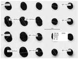
도 2a 및 2b는 예를 들어, 마이크로-퍼포레이션의 평면도 및 다중 마이크로-퍼포레이션의 단면도의 확대된 예(전자 현미경 이미지)를 도시한다. 도 3a 및 3b에 도시된 바와 같이, 마이크로-퍼포레이션의 단면은 패널을 통한 마이크로-퍼포레이션의 길이를 따라 변화할 수 있다. 예를 들어, 도 3a는 모래시계형(또는 "병목" 형) 단면을 도시하며, 여기서 도 3b의 마이크로-퍼포레이션의 단면은 일반적으로 원통형이다. 몇몇 구체예에서, 마이크로-퍼포레이션은 일반적으로 패널의 표면과 수직인 일정한 축을 따르거나, 변화된 축을 따르거나, 패널의 일반 표면에 수직하지 않게 위치될 수 있다.2A and 2B show an enlarged example (electron microscope image) of, for example, a top view of a micro-perforation and a cross-sectional view of multiple micro-perforations. As shown in FIGS. 3A and 3B, the cross-section of the micro-perforations may vary along the length of the micro-perforations through the panel. For example, Figure 3a shows an hourglass (or "bottleneck") cross section, wherein the cross-section of the micro-perforations in Figure 3b is generally cylindrical. In some embodiments, the micro-perforations may be positioned along a certain axis that is generally perpendicular to the surface of the panel, along a changed axis, or not perpendicular to the normal surface of the panel.
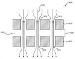
몇몇 구체예에서, 본 개시의 제품은 도 1d에 도시된 바와 같이 다중 패널(예를 들어, 두 겹, 또는 여러-겹의 배열)을 포함할 수 있다. 예를 들어, 몇몇 구체예에서, 제품은 각각 소정의 두께를 갖고, 각각 소정의 직경을 갖는 복수의 마이크로-퍼포레이션을 갖는 제1 및 제2 유리 또는 유리 세라믹 패널(10, 12)를 포함하며; 여기서 패널의 두께 대 마이크로-퍼포레이션의 직경의 비는 25 미만, 20 미만, 또는 약 0.1 내지 20이다. 몇몇 구체예에서, 제1 및 제2 패널은 서로 이격되며 내부-패널 갭(14)를 정의한다. 몇몇 구체예에서, 제1 및 제2 패널은 일반적으로 서로 평행하다. 몇몇 구체예에서, 패널은 서로 다른 거리, 예를 들어, 비-평행 간격, 또는 패널 자체의 치수 변화를 통해 이격될 수 있다. 몇몇 구체예에서, 적어도 하나의 패널의 에지의 적어도 일부는 홀딩 부분에 밀봉된다. 몇몇 구체예에서, 일 이상의 패널은 밀봉된 에지를 가질 수 있거나, 어느 것도 밀봉되지 않을 수 있다. 몇몇 구체예에서, 예를 들어, 균일한 치수 또는 변화하는 치수를 갖는 추가적인 패널이 사용될 수 있다. 몇몇 구체예에서, 다중 패널은 서로 균일하게 이격되거나, 다양한 간격을 가질 수 있다. 일 이상의 구체예에서, 제1 및 제2 유리 또는 유리 세라믹 패널은 서로 동일한 두께 또는 서로 상이한 두께를 갖는다. 예를 들어, 제1 유리 또는 유리 세라믹 패널(10)은 제2 유리 또는 유리 세라믹 패널(12)보다 큰 두께를 가질 수 있다. 또 다른 예에서, 제2 유리 또는 유리 세라믹 패널(12)은 제1 유리 또는 유리 세라믹 패널(10)보다 큰 두께를 가질 수 있다.In some embodiments, the article of manufacture of the present disclosure may include multiple panels (e.g., two layers, or multiple-ply arrangements) as shown in FIG. 1D. For example, in some embodiments, the product includes first and second glass or glass
두 겹의 배열을 포함하는 일 이상의 구체예에서, 제1 및 제2 유리 또는 유리 패널 중 하나 또는 둘 모두의 두께는 약 0.05 mm 내지 6 mm, 약 0.05 mm 내지 3 mm, 약 0.05 mm 내지 2 mm, 약 0.1 mm 내지 3 mm, 약 0.1 mm 내지 2 mm, 약 0.1 mm 내지 약 1 mm, 약 0.1 mm 내지 0.6 mm이다. 예를 들어, 제1 및 제2 유리 또는 유리 패널 중 하나 또는 둘 모두의 두께는 약 0.05 mm 내지 약 6 mm, 약 0.05 mm 내지 약 5 mm, 약 0.05 mm 내지 약 4 mm, 약 0.05 mm 내지 약 3.5 mm, 약 0.05 mm 내지 약 3 mm, 약 0.05 mm 내지 약 2.5 mm, 약 0.05 mm 내지 약 2 mm, 약 0.05 mm 내지 약 1.5 mm, 약 0.05 mm 내지 약 1.2 mm, 약 0.05 mm 내지 약 1 mm, 약 0.1 mm 내지 약 6 mm, 약 0.2 mm 내지 약 6 mm, 약 0.3 mm 내지 약 6 mm, 약 0.4 mm 내지 약 6 mm, 약 0.5 mm 내지 약 6 mm, 약 0.55 mm 내지 약 6 mm, 약 0.7 mm 내지 약 6 mm, 약 0.8 mm 내지 약 6 mm, 약 0.9 mm 내지 약 6 mm, 약 1 mm 내지 약 6 mm, 약 1.1 mm 내지 약 6 mm, 약 1.2 mm 내지 약 6 mm, 약 1.5 mm 내지 약 6 mm, 약 2 mm 내지 약 6 mm, 약 2.5 mm 내지 약 6 mm, 약 3 mm 내지 약 6 mm, 약 0.1 mm 내지 약 1 mm, 약 0.3 mm 내지 약 1 mm, 약 0.4 mm 내지 약 1 mm, 약 0.5 mm 내지 약 1 mm, 또는 약 0.3 mm 내지 약 0.7 mm일 수 있다.In one or more embodiments comprising an arrangement of two plies, the thickness of one or both of the first and second glass or glass panels may be from about 0.05 mm to about 6 mm, from about 0.05 mm to about 3 mm, from about 0.05 mm to about 2 mm From about 0.1 mm to about 3 mm, from about 0.1 mm to about 2 mm, from about 0.1 mm to about 1 mm, from about 0.1 mm to about 0.6 mm. For example, the thickness of one or both of the first and second glass or glass panels may range from about 0.05 mm to about 6 mm, from about 0.05 mm to about 5 mm, from about 0.05 mm to about 4 mm, from about 0.05 mm to about About 0.05 mm to about 2 mm, about 0.05 mm to about 1.5 mm, from about 0.05 mm to about 1.2 mm, from about 0.05 mm to about 1 mm, from about 0.05 mm to about 3 mm, from about 0.05 mm to about 3.5 mm, from about 0.05 mm to about 3 mm, From about 0.1 mm to about 6 mm, from about 0.2 mm to about 6 mm, from about 0.3 mm to about 6 mm, from about 0.4 mm to about 6 mm, from about 0.5 mm to about 6 mm, from about 0.55 mm to about 6 mm, From about 0.7 mm to about 6 mm, from about 0.8 mm to about 6 mm, from about 0.9 mm to about 6 mm, from about 1 mm to about 6 mm, from about 1.1 mm to about 6 mm, from about 1.2 mm to about 6 mm, From about 2 mm to about 6 mm, from about 2.5 mm to about 6 mm, from about 3 mm to about 6 mm, from about 0.1 mm to about 1 mm, from about 0.3 mm to about 1 mm, from about 0.4 mm to about 6 mm 1 mm, from about 0.5 mm to about 1 mm, or from about 0.3 mm to about 0.7 mm .
몇몇 구체예에서, 내부-패널 갭 거리는 특정 주파수를 흡수하기 위한 음향 요건 및 전체 설계의 부분에 따라 변화할 수 있다. 몇몇 구체예에서, 내부-패널 갭은 예를 들어 종횡비, 마이크로-퍼포레이션 크기, 피치, 패널 두께, 및 관심 있는 주파수 범위에 따라 변화될 수 있다. 몇몇 구체예에서, 예를 들어, 시스템이 흡수 스펙트럼(주파수에서)을 넓히거나, 흡수 강도를 증가시키도록 다중 내부-패널 갭을 갖는 추가적인 패널이 포함될 수 있다. 몇몇 구체예에서, 내부-패널 갭에 의해 정의된 패널 간 분리 거리는 약 1 mm 내지 500 mm, 약 1 mm 내지 100 mm, 약 1 mm 내지 50 mm일 수 있다.In some embodiments, the inner-panel gap distance may vary depending on the acoustical requirements to absorb the particular frequency and the portion of the overall design. In some embodiments, the inner-panel gap can be varied depending on, for example, aspect ratio, micro-perforation size, pitch, panel thickness, and frequency range of interest. In some embodiments, for example, additional panels with multiple inner-panel gaps may be included to allow the system to widen the absorption spectrum (at frequency) or increase the absorption intensity. In some embodiments, the separation distance between panels defined by the inner-panel gap may be between about 1 mm and 500 mm, between about 1 mm and 100 mm, between about 1 mm and 50 mm.
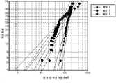
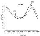
도 4a 및 4b는 2개의 마이크로-퍼포레이팅된 패널에 대한 주파수 밴드를 따른 흡수 계수를 도시한다. 두 도면 모두에서, 수직 입사 흡음(Normal Incidence Acoustic Absorption)은 상이한 캐비티 간격, 즉, 단일 패널 배치를 위한 뒷벽으로부터의 에어 간격에서 측정된다. 이들 도면은 상이한 에어 간격에 대한 모델링된 데이터의 비교를 나타낸다. 도면에서, "1"의 흡수 계수는 완전 흡수를 나타낸다. 캐비티 간격은 피크 흡수 주파수(예를 들어, 도 4b에 도시된 보다 낮은 주파수 스펙트럼 피크)에 영향을 미친다는 것이 관측될 수 있다. 이 테스트에서, 홀/마이크로-퍼포레이션 직경은 200 ㎛였고, 약 1 mm의 피치 및 약 0.5 mm의 두께를 가졌다. 모델 데이터는 전술한 식으로부터 음향 임피던스를 계산하기 위한 코드를 개발하고, 이후 다음의 식을 사용하여 흡수 계수(Maa의 이론)을 계산함으로써 얻어졌으며:Figures 4a and 4b show absorption coefficients along the frequency band for two micro-perforated panels. In both figures, Normal Incidence Acoustic Absorption is measured at different cavity spacing, i.e., air spacing from the rear wall for a single panel layout. These figures show a comparison of modeled data for different air gaps. In the figure, the absorption coefficient of "1 " indicates complete absorption. It can be observed that the cavity spacing affects the peak absorption frequency (e.g., the lower frequency spectral peak shown in Figure 4B). In this test, the hole / micro-perforation diameter was 200 microns and had a pitch of about 1 mm and a thickness of about 0.5 mm. The model data was obtained by developing a code for calculating the acoustic impedance from the above equation and then calculating the absorption coefficient (the theory of Maa) using the following equation:

여기서 α는 흡수 계수이고, Re[Z]는 음향 임피던스의 실수부이며, Im[Z]는 음향 임피던스의 허수부이다.Where [alpha] is the absorption coefficient, Re [Z] is the real part of the acoustic impedance, and Im [Z] is the imaginary part of the acoustic impedance.
유사하게, 도 5a 및 도 5b는 여러 겹의 패널 배열의 2개의 제품에 대한 주파수 밴드를 따른 흡수 계수를 나타낸다. 이 예에서, 테스트가 여러 겹의 패널 배열을 이용함에 따라, 제1 에어 간격은 두 패널 사이에 있으며, 제2 에어 간격은 내부 패널과 뒷벽 사이에 있다. 도면에서, 제1 거리(도 5a에서 약 10 mm, 및 도 5b에서 약 5 mm)는 내부 분리에 대응하며 제2 거리(도 5a에서 약 14 mm, 및 도 5b에서 약 50 mm)는 내부 층과 뒷벽 사이의 거리에 대응한다. 도면에 도시된 바와 같이, 이중 피크는 상이한 거리에 의해 생성된 개별 공명과 관련된다. 유리하게는, 피크 흡수는 층 및/또는 뒷벽 사이의 거리에 기초하여 이동할 것이다.Similarly, Figures 5A and 5B show the absorption coefficients along the frequency bands for the two products of the multi-ply panel arrangement. In this example, the first air gap is between the two panels, and the second air gap is between the inner panel and the back wall, as the test uses multiple layers of panel arrays. 5A) and a second distance (about 14 mm in Fig. 5A and about 50 mm in Fig. 5B) corresponds to the inner separation, And the rear wall. As shown in the figure, the dual peaks are associated with individual resonances produced by different distances. Advantageously, the peak absorption will move based on the distance between the layer and / or the back wall.
예를 들어, 도 6에 도시된 바와 같이, 단일 패널 배열은 두 겹의 패널 배열과 대조된다. 도시된 바와 같이, 다중 패널 배열 모델은 바람직한 흡음율의 보다 넓은 주파수 스펙트럼을 초래한다. 다중 패널 배열은 이의 흡수의 주파수 대역폭을 크게 넓히고 저 주파수 적용 및 고 주파수 적용 모두를 다룰 수 있다. 예를 들어, 두 겹의 패널 배치는 서로 평행하고 이격된 2개의 마이크로-퍼포레이팅된 패널을 포함할 수 있다. 패널은 강성 뒷벽이 있거나 없도록 배열될 수 있다. 단일 마이크로-퍼포레이팅된 패널("MPP")와 유사하게, 두 겹의 마이크로-퍼포레이팅된 패널("DLMPP")는 헬름홀츠 공진기(resonator)를 작동시킨다. 또한, 다중 패널 층과 뒷벽 사이의 간격은 2개의 공명 거동을 결합하고 이의 흡수의 주파수 대역폭을 넓히는 방식으로 배치될 수 있다. 강성 뒷벽이 없는 DLMPP는 공간 흡수체로서 작용하며 회의실 칸막이, 개방된 사무실 공간 등과 같은 영역에서 특히 유리할 수 있다.For example, as shown in FIG. 6, a single panel arrangement is contrasted with a two-layer panel arrangement. As shown, the multiple panel array model results in a wider frequency spectrum of the desired sound absorption rate. The multi-panel arrangement can greatly broaden the frequency bandwidth of its absorption and handle both low frequency and high frequency applications. For example, a two-ply panel arrangement may include two micro-perforated panels that are parallel and spaced from each other. The panel may be arranged with or without a rigid rear wall. Similar to a single micro-perforated panel ("MPP"), a two-layer micro-perforated panel ("DLMPP") operates a Helmholtz resonator. In addition, the spacing between the multiple panel layers and the back wall can be arranged in such a way as to combine the two resonance behaviors and broaden the frequency bandwidth of their absorption. DLMPP without rigid rear wall acts as a space absorber and can be particularly advantageous in areas such as conference room divisions, open office spaces, and the like.
본 개시의 몇몇 구체예는: (i) 레이저 빔에 의해 복수의 손상 트랙을 유리 또는 유리 세라믹 패널로 형성하는 단계, 여기서 상기 패널은 평면 내에서 연장하며 소정의 두께를 갖고, 여기서 상기 손상 트랙은 제1 직경을 가지며; 및 (ii) 제2 직경을 갖는 마이크로-퍼포레이션을 갖는 마이크로-퍼포레이팅된 패널을 형성하기 위해 (i)로부터 얻어진 패널을 산 용액 내에서 에칭하는 단계를 포함하는 유리 또는 유리 세라믹 패널의 형성 방법에 관한 것이며, 여기서 상기 마이크로-퍼포레이팅된 패널의 NRC는 약 0.3 내지 1, 또는 약 0.3 내지 0.8이다.Some embodiments of the present disclosure may include: (i) forming a plurality of damaged tracks by a laser beam into a glass or glass ceramic panel, wherein the panel extends in a plane and has a predetermined thickness, Having a first diameter; And (ii) etching the panel obtained from (i) in an acid solution to form a micro-perforated panel having micro-perforations having a second diameter. Wherein the NRC of the micro-perforated panel is about 0.3 to 1, or about 0.3 to 0.8.
상기 방법은 일반적으로 도 7 내지9에 개략적으로 도시된다. 몇몇 구체예에서, 레이저 빔은 빔 전파 방향을 따라 지향된 초점 라인을 가지며 레이저 빔 초점 라인을 패널 내로 향하게 하는 펄스 레이저 빔이다. 몇몇 구체예에서, 상기 방법은 유리를 제1 산 용액과 상이한 제2 산 용액 내에서 에칭하는 단계를 더욱 포함한다. 몇몇 구체예에서, 상기 방법은 마이크로-퍼포레이팅된 패널을 화학적 또는 열적으로 강화하는 단계를 더욱 포함한다. 몇몇 구체예에서, 유리 또는 유리 세라믹 패널은 고-강도 유리 또는 유리 세라믹 조성물을 포함한다. 몇몇 구체예에서, 유리 또는 유리 세라믹 패널의 두께는 약 0.05 mm 내지 6 mm이다.The method is generally illustrated schematically in Figures 7 to 9. In some embodiments, the laser beam is a pulsed laser beam having a focused focal line along the beam propagation direction and directing the laser beam focal line into the panel. In some embodiments, the method further comprises the step of etching the glass in a second acid solution different from the first acid solution. In some embodiments, the method further comprises chemically or thermally enhancing the micro-perforated panel. In some embodiments, the glass or glass ceramic panel comprises a high-strength glass or glass ceramic composition. In some embodiments, the thickness of the glass or glass ceramic panel is about 0.05 mm to 6 mm.
몇몇 구체예에서, 레이저 빔은 Gauss-Bessel 레이저 빔에 이어서 화학적 에칭될 수 있다. 몇몇 구체예에서, 상기 방법은 높은 처리량을 갖는 대규모 공정으로 배열될 수 있다. 몇몇 구체예에서, 상기 방법은 예를 들어, 1' × 1'(1 피트 × 1 피트) 이상의 큰 크기의 패널을 제조하는데 사용될 수 있다. 상기 방법은 홀의 고밀도 어레이(array)를 제조하는 고속 공정이며 조정을 위한 다양한 마이크로-홀 형상, 크기, 마이크로-홀 위치 및 밀도를 제조하고 원하는 음향 성능을 제조하기 위한 유연성을 제공한다. 또한, 마이크로-퍼포레이팅된 패널은 본원에 기술된 바와 같이, 우수한 강도를 달성하기 위해 에칭 후 열적 또는 화학적으로 강화된다.In some embodiments, the laser beam may be chemically etched following a Gauss-Bessel laser beam. In some embodiments, the method can be arranged in a large scale process with high throughput. In some embodiments, the method may be used to fabricate large size panels, for example, 1 'x 1' (1 foot x 1 foot) or more. The method is a high-speed process for fabricating high density arrays of holes and provides flexibility for manufacturing various micro-hole shapes, sizes, micro-hole positions and densities for adjustment and producing desired acoustic performance. In addition, the micro-perforated panel is thermally or chemically strengthened after etching to achieve good strength, as described herein.
도 7은 레이저 빔의 라인 초점을 사용하여 환경에 따른 패널 내의 손상 트랙(예를 들어, 패널 내 결함 또는 개방된 영역) 또는 홀을 생성하는 드릴링 방법의 대표적인 개략도를 도시한다. 도 8에 도시된 바와 같이, 레이저 버스트 패턴(방출 대 시간)은 특정 필요에 기초하여 조정될 수 있다. 레이저 시스템(예를 들어, 피코 초(picosecond) 레이저)의 대표적인 패턴은 일 이상의 펄스를 함유할 수 있는 버스트에 의해 특징지어질 수 있다. 버스트의 주파수는 예를 들어 약 100 kHz(10 μsec)과 같이 레이저의 반복 속도를 정의한다. 서브-펄스 사이의 시간은 예를 들어 약 20 nsec와 같이 훨씬 짧을 수 있다. 패널의 두께 대 마이크로-퍼포레이션 직경의 비가 매우 낮은 경우, 레이저 드릴링 작동 대신 커팅 작동이 사용될 수 있다.Figure 7 shows an exemplary schematic diagram of a drilling method for creating damaged tracks (e.g., defects in the panel or open areas) or holes in the panel depending on the environment using the line focus of the laser beam. As shown in FIG. 8, the laser burst pattern (emission versus time) can be adjusted based on a particular need. A representative pattern of a laser system (e.g., a picosecond laser) may be characterized by a burst that may contain one or more pulses. The frequency of the burst defines the repetition rate of the laser, for example, about 100 kHz (10 μsec). The time between sub-pulses may be much shorter, for example about 20 nsec. If the ratio of panel thickness to micro-perforation diameter is very low, a cutting operation may be used instead of a laser drilling operation.
몇몇 구체예에서, 상기 방법은 비-회절 레이저 빔, 예를 들어, Gauss-Bessel 빔을 이용하는 단계를 포함한다. 이러한 유형의 빔은 회절 효과가 빔 발산에 강한 영향을 미치기 전에 상당한 거리 동안 전파할 수 있으므로, 초점을 맞출 때, 축 강도는 가우시안 빔에 비해 훨씬 느리게 감쇠한다. Gauss-Bessel 빔을 생성하기 위해, 액시콘(axicon)은 시준(collimating) 렌즈 및 초점 렌즈와 결합될 수 있다. 광학 요소의 정확한 특성(액시콘 정점 각, 렌즈 초점 거리, 광학 요소 사이의 분리 등)은 라인 초점의 특성에 기여한다.In some embodiments, the method includes using a non-diffracting laser beam, e.g., a Gauss-Bessel beam. This type of beam attenuates the axis intensity much slower than the Gaussian beam when focusing, since the diffraction effect can propagate for a considerable distance before it has a strong influence on beam divergence. To generate a Gauss-Bessel beam, an axicon may be combined with a collimating lens and a focusing lens. The exact nature of the optical element (axicon vertex angle, lens focal length, separation between optical elements, etc.) contributes to the characteristics of the line focus.
몇몇 구체예에서, 약 1064 nm 및 약 532 nm에서 작동하는 Nd:YAG 레이저가 사용될 수 있다. 몇몇 구체예에서, 스펙트럼의 근적외선과 대략 UV 범위 사이의 레이저 파장이 사용될 수 있다. 레이저는 약 10 ㎲ 이상(반복 속도) 분리된 일 시리즈의 버스트를 생성할 수 있다. 각 버스트는 약 2 내지 약 20 펄스의 범위 내의 사용자에 의해 선택된 다수의 펄스를 함유할 수 있다. 몇몇 구체예에서, 단일 펄스 버스트가 사용될 수 있다. 각 펄스는 약 10 ps의 지속 시간을 가질 수 있다. 몇몇 구체예에서, 인접 펄스 사이의 시간은 약 20 ns(레이저 주파수)일 수 있다. 레이저 주파수는 레이저 설계 내의 오실레이터(oscillator)의 기본 주파수에 의해 결정될 수 있다.In some embodiments, an Nd: YAG laser operating at about 1064 nm and about 532 nm may be used. In some embodiments, a laser wavelength between near-infrared and approximately UV range of the spectrum can be used. A laser can produce bursts of a series of days separated by about 10 ㎲ or more (repetition rate). Each burst may contain a plurality of pulses selected by the user in the range of about 2 to about 20 pulses. In some embodiments, a single pulse burst may be used. Each pulse may have a duration of about 10 ps. In some embodiments, the time between adjacent pulses may be about 20 ns (laser frequency). The laser frequency can be determined by the fundamental frequency of the oscillator in the laser design.
유리하게는, 펄스 분리는 버스트 효과를 최적화하기 위해 약 < 100 ns로 설정될 수 있다.Advantageously, the pulse separation can be set to about < 100 ns to optimize the burst effect.
몇몇 구체예에서, Gauss-Bessel 빔의 횡 및 축 에너지 분포는 제어될 수 있다. 몇몇 구체예에서, 횡 분포의 중심 로브(lobe)에서의 레이저 직경(예를 들어, 최대 세기의 절반에서의 빔의 전체 폭)은 축 분포에 대해 약 1 ㎛ 및 약 1.35 mm이다.In some embodiments, the transverse and axial energy distributions of the Gauss-Bessel beam can be controlled. In some embodiments, the laser diameter at the center lobe of the lateral distribution (e.g., the total width of the beam at half the maximum intensity) is about 1 μm and about 1.35 mm for axial distribution.
몇몇 구체예에서, 손상 트랙을 초래하는 에너지 범위는 버스트 당 약 50 μJ 내지 약 200 μJ이다. 몇몇 구체예에서, 손상 트랙을 초래하는 에너지 범위는 예를 들어, 광학적 배열, 버스트 수, 유리 조성물 등에 따라 변화될 수 있다. 정확한 타이밍, 펄스 지속 시간, 및 반복 속도는 레이저 설계에 따라 변화할 수 있다.In some embodiments, the energy range that results in a damage track is about 50 μJ to about 200 μJ per burst. In some embodiments, the energy range that results in a damage track may vary, for example, depending on the optical configuration, number of bursts, glass composition, and the like. The exact timing, pulse duration, and repetition rate may vary depending on the laser design.
유리하게는, 높은 세기의 비교적 짧은 펄스(예를 들어, 약 < 15 psec)가 사용될 수 있다.Advantageously, relatively high pulses of high intensity (e.g., about < 15 psec) can be used.
몇몇 구체예에서, 최적의 광학 요소 및 레이저 조건은 패널 두께보다 긴 레이저 강도(라인 초점)의 영역을 생성하는데 사용된다. 세기가 충분히 높으면, 패널과의 레이저 상호 작용은 비선형 체제로 떨어지며, 2가지 광자 흡수, 그 중에서도 Kerr 효과, 및 케스케이드(casecade) 이온화를 포함한다. 레이저에 의해 생성된 손상 트랙은 습식 에칭 공정의 우선적인 경로 역할을 한다. 손상 트랙은 홀 당 단일 보스트를 사용하여 약 2 mm 까지의 깊이일 수 있다. 이들 손상 트랙은 일반적으로 약 0.5 ㎛ 내지 약 1.5 ㎛의 내부 치수를 갖는 홀의 형태를 취할 수 있다.In some embodiments, the optimal optical element and laser conditions are used to create regions of laser intensity (line focus) that are longer than the panel thickness. If the intensity is high enough, the laser interaction with the panel falls into a non-linear regime and involves two photon absorption, especially Kerr effect, and cascade ionization. The damaged track created by the laser serves as a preferred path for the wet etch process. Damaged tracks can be as deep as about 2 mm using a single bost per hole. These damaged tracks can generally take the form of holes with internal dimensions of about 0.5 [mu] m to about 1.5 [mu] m.
몇몇 구체예에서, 마이크로-홀의 어레이(최종적인 마이크로-퍼포레이션이 될)는 전술한 바와 같이 형성될 수 있다. 몇몇 구체예에서, 패널 상의 홀의 목표 위치는 좌표의 세트로서 레이저 처리 머신에 업로드된다. 몇몇 구체예에서, 머신 래스터(raster)는 패널을 스캔하고 홀이 원할 때마다 레이저가 발사되도록 레이저 방아쇠를 동기화한다. 몇몇 구체예에서, 상기 단계는 약 1 m/s로 이동하며 래스터 당 시간은 홀 밀도와는 독립적일 수 있다.In some embodiments, an array of micro-holes (to be the final micro-perforations) may be formed as described above. In some embodiments, the target position of the hole on the panel is uploaded to the laser processing machine as a set of coordinates. In some embodiments, the machine raster scans the panel and synchronizes the laser trigger so that the laser is fired whenever the hole is desired. In some embodiments, the step moves at about 1 m / s and the time per raster may be independent of the hole density.
몇몇 구체예에서, 레이저 손상 패널(예를 들어, 유리 패널)은 이후 산 에칭되어 원하는 직경 및 형상으로 홀을 개방한다. 유리의 산 에칭 처리는 예를 들어, 불화 수소산(HF) 계 용액을 사용하여, 물질을 레이저에 의해 생성된 우선적인 손상 트랙으로부터 화학적으로 공격 및 제거하도록 수행될 수 있다. 몇몇 구체예에서, 이 반응이 발생하는 동안, 알칼리 또는 알루미노플루오르화물과 같은 부산물이 유리 조성물에 따라 생성된다. 이들 부산물은 HF에 비교적 불용성이다. 몇몇 구체예에서, 2차 무기산, 예를 들어, 질산(HNO3)이 첨가된다. 질산의 첨가는 에칭 홀의 막힘을 방지하고 욕의 수명을 연장하기 위해 전체 에칭 속도 뿐 아니라 이들 에천트(etchant) 부산물의 용해도를 증가시킨다.In some embodiments, a laser damage panel (e.g., a glass panel) is then acid etched to open the hole with the desired diameter and shape. The acid etching treatment of the glass can be performed, for example, using a hydrofluoric acid (HF) based solution to chemically attack and remove the material from the preferred damage track generated by the laser. In some embodiments, byproducts, such as alkali or aluminofluoride, are produced according to the glass composition during this reaction. These by-products are relatively insoluble in HF. In some embodiments, a secondary inorganic acid, such as nitric acid (HNO3 ), is added. The addition of nitric acid increases the overall etch rate as well as the solubility of etchant byproducts in order to prevent clogging of the etch holes and extend the life of the bath.
몇몇 구체예에서, 도 9에 도시된 바와 같이, 에칭된 마이크로-퍼포레이션의 형상은 반응 속도 대 확산 속도의 비에 의존할 수 있다. 반응 속도는 표면 상의 벌크 유리의 에칭 속도(E1)에 직접 영향을 주는 반면, 확산 속도는 홀의 에칭 속도(E2)를 구동한다. 반응 속도 또는 효과적인 에칭 속도는 동역학에 의해 구동되며 에천트 화학, 유리 조성물, 및 온도에 의해 제어될 수 있다. 예를 들어, 보다 농축된 HF 용액, 보다 약한 결합 네트워크의 유리, 또는 증가된 욕 온도의 사용은 모두 보다 많은 가용성 히드로늄 및 불소 이온을 도입하고 이들이 보다 높은 속도로 반응하는 것을 허용하도록 에너지를 첨가함으로써 시스템의 반응 속도를 증가시킬 수 있다. 확산 속도는 이러한 활성 이온이 새로운 유리 분자와 반응하기 위해 벌크 또는 유리 내부로 도입되는 속도이다. 확산은 교반(예를 들어, 초음파 및 재순환), 부품의 습윤성, 및 온도와 같은 많은 인자에 의해 영향을 받을 수 있다. 이러한 파라미터를 조정함으로써 마이크로-퍼포레이션의 형상은 모래시계로부터 원통형 개구로 조정될 수 있다. 비-원형 개구 및 비-원형 원통형 마이크로-퍼포레이션의 예가 예를 들어 도 10 및 11에 도시된다.In some embodiments, as shown in Figure 9, the shape of the etched micro-perforations may depend on the ratio of the reaction rate to the diffusion rate. The reaction rate directly affects the etching rate E1 of the bulk glass on the surface, while the diffusion rate drives the etching rate E2 of the hole. The reaction rate or effective etch rate is driven by kinetic and can be controlled by etch chemistry, glass composition, and temperature. For example, the use of a more concentrated HF solution, a weaker binding network, or an increased bath temperature all adds energy to allow more soluble hydronium and fluorine ions to be introduced and to allow them to react at a higher rate The reaction speed of the system can be increased. The diffusion rate is the rate at which these active ions are introduced into the bulk or glass to react with the new glass molecule. Diffusion can be affected by many factors such as agitation (e.g., ultrasonic and recirculation), wettability of components, and temperature. By adjusting these parameters, the shape of the micro-perforations can be adjusted from an hourglass to a cylindrical opening. Examples of non-circular apertures and non-circular cylindrical micro-perforations are shown, for example, in FIGS. 10 and 11.
예를 들어, 몇몇 구체예에서, 사용된 산 에천트는 약 1.0 ㎛/분의 효과적인 에칭 속도를 갖는 약 1.5 M 불화 수소산 및 약 1.6 M 질산이다. 패널은 약 40 kHz의 출력 주파수를 갖는 직접 커플링된(coupled), 베이스 초음파 변환기(transducer)가 장착된 JST 에칭 시스템 내에서 에칭될 수 있다. 몇몇 구체예에서, 상기 패널은 약 300 mm/s에서 수직으로 교반되는 반면 에천트는 욕 내에서 버텀(bottom)으로부터 탑(top)까지 재순환된다. 이 교반은 홀 내로의 확산을 증가시키고 유리 표면과 만나는 초음파를 균질화하는 것을 돕는다. 몇몇 구체예에서, 욕 온도는 버텀으로부터 냉각 에천트를 펌핑함으로써 약 20.3 ℃(약 +/- 0.1 ℃ 내)로 유지된다. 초음파에 의해 가열된 보다 따뜻한 에천트는 오버플로우(overflow)되고 칠러(chiller)를 통해 다시 전달된다. 에칭 공정의 이러한 배열은 생성되는 마이크로-퍼포레이션이 개방되고 실질적으로 원통형일 수 있도록 손상 트랙 내로의 적절한 양의 산의 확산을 허용한다. 홀 내에서 보다 많은 모래시계 형상을 얻기 위해, 시스템 내의 초음파는 홀 낸로의 확산을 감소시키도록 턴 오프(turn off)될 수 있으며, 이는 차례로 홀 내부의 에칭 속도(E2)를 감소시킨다. 홀의 형상은 농도, 온도, 교반 등과 같은 파라미터를 조정하여 확산 속도 대 반응 속도의 비를 조정함으로써 조정될 수 있다.For example, in some embodiments, the acid etchant used is about 1.5 M hydrofluoric acid and about 1.6 M nitric acid with an effective etch rate of about 1.0 micrometer / minute. The panel can be etched in a JST etched system with a direct coupled coupled, bass ultrasonic transducer having an output frequency of about 40 kHz. In some embodiments, the panel is vertically agitated at about 300 mm / s, while the etchant is recycled from the bottom to the top in the bath. This agitation helps to increase the diffusion into the holes and to homogenize the ultrasonic waves that meet the glass surface. In some embodiments, the bath temperature is maintained at about 20.3 캜 (within about +/- 0.1 캜) by pumping the chill etchant from the bottom. The warmer etchant heated by the ultrasonic waves overflows and passes back through the chiller. This arrangement of the etching process allows diffusion of the appropriate amount of acid into the damaged track so that the resulting micro-perforations are open and substantially cylindrical. In order to obtain more hourglass shapes within the hole, the ultrasonic waves in the system can be turned off to reduce the diffusion into the hole, which in turn reduces the etch rate E2 inside the hole. The shape of the holes can be adjusted by adjusting the ratio of the diffusion rate to the reaction rate by adjusting parameters such as concentration, temperature, stirring, and the like.
에칭 후에, 몇몇 구체예에서, 패널은 마이크로-퍼포레이팅된 패널을 강화시키기 위해 템퍼링되거나, 화학적으로 처리(예를 들어, 이온-교환 작업)될 수 있다.After etching, in some embodiments, the panel may be tempered or chemically treated (e.g., ion-exchange operation) to strengthen the micro-perforated panel.
본 개시는 또한 전술한 것과 유사한 유리 또는 유리 세라믹 패널 내에 마으크로-퍼포레이션을 형성하는 방법을 제공한다. 도 12에 도시된 바와 같이, 예를 들어, 상기 방법은 레이저 빔에 의해 손상 패널의 서브셋을 유리 또는 유리 세라믹 패널로 형성하는 단계를 포함하며, 여기서 손상 트랙은 패턴을 형성하도록 위치된다. 몇몇 구체예에서, 레이저는 몇몇 레이저 펄스를 사용하여 물질을 손상시킨다. 몇몇 구체예에서, 레이저 공정은 가깝게 인접한 손상 트랙의 군을 생성하고, 이는 이후 함께 병합되어 최종 마이크로-퍼포레이팅된 패널을 생성하기 위해 에칭 공정 동안 보다 큰 홀을 형성한다. 몇몇 구체예에서, 손상 트랙의 레이아웃(layout)은 병합될 때 레이저 손상 트랙 위치가 지정된 형상(예를 들어, 원, 삼각형, 정사각형, 다른 다각형, 비-선형, 텍스트 또는 숫자, 로고, 꽃과 같은 장식 패턴 등)을 형성할 수 있도록 레이저 손상 트랙 위치를 미리-위치시킴으로써 임의의 형상을 생성하는데 사용될 수 있다. 몇몇 구체예에서, 전술한 방법과 유사하게, 상기 방법은 레이저 빔에 의해 복수의 손상 트랙을 유리 또는 유리 세라믹 패널로 형성하는 단계를 포함하며, 여기서 패널은 평면 내에서 연장하고 소정의 두께를 가지며, 여기서 손상 트랙은 제1 직경을 갖는다. 몇몇 구체예에서, 상기 방법은 손상 트랙의 서브셋이 제2 직경을 갖는 마이크로-퍼포레이션을 갖는 마이크로-퍼포레이팅된 패널을 형성하기 위해 병합하도록 패널을 산 용액 내에서 에칭하는 단계를 포함한다(예를 들어, 도 12에 도시된 바와 같음). 몇몇 구체예에서, 단일 레이저가 손상 트랙을 생성하는데 사용될 수 있다. 몇몇 구체예에서, 다중 레이저가 손상 트랙을 생성하는데 사용될 수 있다. 몇몇 구체예에서, 검류계 시스템이 손상 트랙을 생성하는데 사용될 수 있다.The present disclosure also provides a method of forming a mica-perforation within a glass or glass ceramic panel similar to that described above. As shown in FIG. 12, for example, the method includes forming a subset of the damaged panel with a laser beam into a glass or glass ceramic panel, wherein the damaged track is positioned to form a pattern. In some embodiments, the laser uses some laser pulses to damage the material. In some embodiments, the laser process creates a group of closely adjacent damaged tracks, which are then merged together to form a larger hole during the etching process to produce the final micro-perforated panel. In some embodiments, the layout of the damaged track is such that when the laser damaged track position is merged, the position of the laser damage track is matched to the specified shape (e.g., circle, triangle, square, other polygon, non- Can be used to create any shape by pre-positioning the position of the laser damaged track so that it can form a pattern (e.g., a decorative pattern, etc.). In some embodiments, similar to the method described above, the method comprises forming a plurality of damaged tracks by a laser beam into a glass or glass ceramic panel, wherein the panel extends in a plane and has a predetermined thickness , Wherein the damaged track has a first diameter. In some embodiments, the method includes etching the panel in an acid solution such that the subset of damaged tracks merges to form a micro-perforated panel having micro-perforations having a second diameter For example, as shown in FIG. 12). In some embodiments, a single laser may be used to generate a damaged track. In some embodiments, multiple lasers can be used to generate a damaged track. In some embodiments, a galvanometer system can be used to generate a damaged track.
도 12에 도시된 바와 같이, 각각의 손상 트랙은 원하는 형상의 홀 애퍼쳐(aperture) 형상(예를 들어, 도 12의 원형)이 얻어질 때까지 물질이 에칭될 때 이들이 홀을 형성하도록 병합하도록 배열될 수 있다. 이와 관련하여, 임의의 형상은 손상 트랙의 위치 및 에칭 공정에 기초하여 달성될 수 있다.As shown in FIG. 12, each damaged track may be patterned such that when the material is etched until it has a hole shape of the desired shape (e.g., the circle of FIG. 12) Lt; / RTI > In this regard, any shape can be achieved based on the location of the damaged track and the etching process.
도 13을 참조하면, 유사한 방법은 레이저 빔에 의해 손상 트랙의 서브셋을 유리 또는 유리 세라믹 패널로 형성하는 단계, 여기서 손상 트랙은 지엽적인 패턴을 형성하기 위해 위치되며; 레이저 빔에 의해 복수의 손상 트랙을 유리 또는 유리 세라믹 패널로 형성하는 단계, 여기서 패널은 평면 내에서 연장하고 소정의 두께를 가지며, 여기서 손상 트랙은 제1 직경을 갖고; 및 손상 트랙의 서브셋이 패널의 섹션을 제거하고 제2 직경을 갖는 마이크로-퍼포레이션을 갖는 마이크로-퍼포레이팅된 패널을 형성하도록 패널을 산 용액 내에서 에칭하는 단계에 의해 사용될 수 있다. 이와 관련하여, 보다 큰 홀이 형성될 수 있다(예를 들어 약 1.0 mm 초과의 직경). 몇몇 구체예에서, 지엽적인 패턴은 손상 트랙이 원하는 형상의 패널의 섹션을 제거하기 위해 병합되도록 임의의 형상으로 배열될 수 있다.Referring to FIG. 13, a similar method comprises forming a subset of damaged tracks with a laser beam into a glass or glass ceramic panel, wherein the damaged track is positioned to form a localized pattern; Forming a plurality of damaged tracks by a laser beam into a glass or glass ceramic panel, wherein the panel extends in a plane and has a predetermined thickness, wherein the damaged track has a first diameter; And a subset of the damaged track can be used by etching the panel in an acid solution to remove the section of the panel and form a micro-perforated panel with micro-perforations having a second diameter. In this regard, larger holes may be formed (e.g., diameters of greater than about 1.0 mm). In some embodiments, the localized pattern can be arranged in any shape such that the damaged track is merged to remove the section of the panel of the desired shape.
몇몇 구체예에서, 레이저는 버스트 패턴 또는 위치의 제어를 통해 서로 가까운 복수의 손상 트랙을 형성하기 위해 단일 또는 다중의 작은 인접한 손상 트랙을 생성하도록 프로그래밍될 수 있다. 몇몇 구체예에서, 인접한 손상 트랙 사이의 간격은 패널 상의 원하는 퍼포레이션 형상 또는 퍼포레이션 크기로 조정될 수 있다. 예를 들어, 타원형 홀 형상을 생성하기 위해, 레이저는 중심 라인을 따라 보다 인접한 손상 트랙을 생성하고 중심 라인 위, 아래의 보다 적은 손상 트랙을 생성하도록 프로그래밍될 수 있다. 산 용액 내에서 에칭할 때, 이 패턴은 단일 레이저 손상 트랙을 갖는 원형 홀 형상을 생성하는 것과는 대조적으로 타원형을 생성할 것이다.In some embodiments, the laser can be programmed to produce single or multiple small contiguous damaged tracks to form a plurality of damaged tracks close together via control of the burst pattern or position. In some embodiments, the spacing between adjacent damaged tracks can be adjusted to the desired perforation shape or perforation size on the panel. For example, to create an elliptical hole shape, a laser may be programmed to create a more abraded damage track along the center line and produce less damage tracks above and below the center line. When etching in an acid solution, this pattern will create an ellipse as opposed to creating a circular hole shape with a single laser damage track.
몇몇 구체예에서, 레이저는 유리의 특정 섹션 상의 다중의 손상 트랙을 갖는 유리를 때리고, 또한 다른 섹션 상의 보다 적은 손상 트랙을 생성하기 위해 이를 때리도록 프로그래밍될 수 있다. 몇몇 구체예에서, 레이저는 동일한 위치에서 유리를 여러 번 때리도록 프로그래밍될 수 있다. 에칭 시, 이는 패널을 따라 상이한 홀 크기를 갖는 패널을 생성할 것이며, 이는 패널의 표면을 따른 마이크로-퍼포레이션 크기의 제어를 허용한다.In some embodiments, the laser can be programmed to strike the glass with multiple damage tracks on a particular section of the glass and hit it to produce less damage tracks on other sections. In some embodiments, the laser can be programmed to beat the glass several times at the same location. Upon etching, this will create panels with different hole sizes along the panel, which allows control of the micro-perforation size along the surface of the panel.
유리하게는, 몇몇 구체예에서, 이러한 특정 방법은 고속 마이크로-퍼포레이션 공정을 초래한다. 서로 인접한 복수의 손상 트랙을 생성하기 위해 다중의 레이저 펄스의 사용, 이후 보다 큰 퍼포레이션 또는 홀을 형성하기 위해 손상 트랙을 연결하기 위한 화학적 에칭 공정에 의해, 이 공정은 이러한 퍼포레이션/홀을 생성하기 위한 속도를 증가시킨다. 차례로, 마이크로-퍼포레이션 또는 홀은 음향 적용 또는 다른 적용, 예를 들어, 장식 목적을 위한 사용에 적용될 수 있다.Advantageously, in some embodiments, this particular method results in a high-speed micro-perforation process. By the use of multiple laser pulses to create a plurality of damaged tracks adjacent to each other, followed by a chemical etch process to connect the damaged tracks to form larger perforations or holes, the process creates such perforations / holes To increase the speed to do so. In turn, the micro-perforations or holes can be applied for acoustic applications or for other applications, for example for decorative purposes.
단일 레이저 펄스가 우선적인 손상 트랙을 생성하기 위해 사용되고, 이후 퍼포레이션을 원하는 크기 또는 형상으로 확대하기 위한 화학적 에칭이 뒤따르는 전술한 공정과 비교하여, 인접한 손상 트랙을 형성하기 위해 다중 레이저 펄스를 이용하는 공정은 화학적 에칭 시간을 현저히 감소시켜, 단일 레이저 펄스 방법의 속도보다 적어도 약 1.5배 큰 공정을 초래한다. 유리하게는, 몇몇 레이저 펄스를 사용하는 방법은 두꺼운 유리 내에서 높은 종횡 비의 홀의 제조의 용이성을 강화하여, 보다 낮은 유리 두께 감소를 달성한다. 차례로, 이러한 이점은 제조 비용을 감소시키며(부분적으로는 감소된 에칭 시간), 고밀도 마이크로-퍼포레이션이 비교적 빠르게 형성되는 것을 허용하며, 마이크로-퍼포레이팅된 유리 패널의 제조 처리량을 증가시킨다. 이 공정의 현재 원가 동인(cost driver)은 에칭 공정이며, 에칭 시간, 유해 폐기물, 안전 위험 등을 감소시키는 공정을 이용하는 것이 유리하다. 또한, 다중의 손상 트랙을 이용하는 이 공정은 유리 패널의 두께 감소를 초래하고, 따라서 에칭 공정으로부터의 감소된 거칠기/표면 파형(waviness)/표면 결함을 통해 표면 품질을 향상시킨다. 또한, 상기 공정은 감소된 왜곡 및 증가된 광학 품질을 초래한다.Compared to the process described above in which a single laser pulse is used to produce a preferential damage track and then a chemical etch to magnify the perforation to the desired size or shape, The process significantly reduces the chemical etch time resulting in a process that is at least about 1.5 times faster than the speed of a single laser pulse method. Advantageously, the method of using some laser pulses enhances ease of manufacture of high aspect ratio holes in thick glass, resulting in lower glass thickness reduction. In turn, this advantage reduces manufacturing costs (partially reduced etch time), allowing dense micro-perforations to be formed relatively quickly and increasing the throughput of manufacturing micro-perforated glass panels. The current cost driver for this process is an etching process, and it is advantageous to use a process that reduces etch time, hazardous waste, safety hazards, and the like. In addition, this process, using multiple damage tracks, results in a reduction in the thickness of the glass panel and thus improves surface quality through reduced roughness / surface waviness / surface defects from the etching process. In addition, the process results in reduced distortion and increased optical quality.
또한, 몇몇 레이저 펄스를 이용하는 것은 에칭 시간이 상당히 감소되기 때문에, 높은 종횡 비의 마이크로-퍼포레이션 또는 홀이 생성될 필요가 있을 때(예를 들어, 건축 또는 자동차 적용에서와 같이 비교적 두꺼운 유리를 사용하는 퍼포레이팅된 흡음 유리에서) 특히 유리하다. 또한, 몇몇 레이저 펄스를 이용하는 것은 단일 시트 상에 다양한 크기 및 형상의 퍼포레이션/홀을 생성할 필요가 있을 때 특히 유리하다. 예를 들어, 마이크로-퍼포레이션은 전술한 바와 같이 다양한 형상으로 형성될 수 있다. 퍼포레이션 또는 홀의 상이한 크기, 형상, 또는 밀도는 몇몇 별도의 드릴링 및 에칭 단계를 필요로 하지 않고 상이한 수의 다양한 패턴의 레이저 생성 손상 트랙을 이용하는 단일 공정을 사용하여 단일 시트 상에 형성될 수 있다. 퍼포레이션의 단면은 또한 예를 들어, 단면이 일반적으로 원통형이거나 "모래시계" 형상인지에 대한 제어를 제공하여 제어될 수 있다.Also, the use of some laser pulses is advantageous when the micro-perforations or holes of high aspect ratios need to be generated (e.g., using relatively thick glass, such as in architectural or automotive applications) In a perforated sound absorbing glass). In addition, the use of some laser pulses is particularly advantageous when it is necessary to generate perforations / holes of various sizes and shapes on a single sheet. For example, the micro-perforations may be formed in various shapes as described above. Different sizes, shapes, or densities of perforations or holes may be formed on a single sheet using a single process that utilizes different numbers of different patterns of laser-generated damaged tracks without the need for some separate drilling and etching steps. The cross section of the perforations may also be controlled, for example, by providing control over whether the cross section is generally cylindrical or "hourglass" shape.
마지막으로, 다중 손상 트랙, 허용 가능한 공정 공차(tolerance)를 이용하는 방법은 레이저 드릴링 및 에칭 모두에 대해 보다 클 수 있으며, 이는 특히 큰 시트에 대해, 위험을 감소시키고 수율을 향상시킨다. 이는 생성되는 다중 레이저 드릴 홀이 에칭 공정을 비교적 덜 중요하게 하고, 또한 레이저 드릴링 공정이 각각의 홀 품질은 몇몇 레이저 드릴 홀이 에칭 후에 하나의 홀로 합병될 때 보다 적은 충격을 가질 것이기 때문에 비교적 덜 중요해지기 때문이다.Finally, multiple damage tracks, methods using acceptable process tolerances, can be greater for both laser drilling and etching, which reduces risk and improves yield, especially for large sheets. This makes it relatively less important for the etch process to be produced and the laser drilling process is relatively less important because each hole quality will have less impact when several laser drill holes are merged into one hole after etching It is because.
도 14를 참조하면, 구체예에 따른 다양한 마이크로-퍼포레이션 직경을 갖는 마이크로-퍼포레이팅된 패널 배치의 다양한 주파수에 걸친 예시적인 흡음율이 도시된다. 각각의 경우에, 주파수 범위에 걸친 예측된 흡음율은 1.7 mm의 일정한 홀 간격의 다양한 마이크로-퍼포레이션/홀 크기를 갖는 0.5 mm 두께의 마이크로-퍼포레이팅된 유리에 대해 나타난다. 구체적으로, 각각 200 ㎛, 500 ㎛, 및 200 ㎛ 및 500 ㎛ 모두의 마이크로-퍼포레이션 직경을 갖는 패널이 도시된다. 도시된 바와 같이, 다양한 홀 크기를 갖는 유리 패널은 부분적으로 음향 및 구조적 패널 모드에 적용되는 중첩의 원리로 인해 단일 홀 크기에 비해 강화된 음향 성능을 가질 수 있다.Referring to Fig. 14, an exemplary sound absorption rate over various frequencies of a micro-perforated panel arrangement with various micro-perforation diameters according to an embodiment is shown. In each case, the predicted absorption rate over the frequency range is shown for a 0.5 mm thick micro-perforated glass with various micro-perforation / hole sizes with a constant hole spacing of 1.7 mm. Specifically, panels having micro-perforation diameters of 200 μm, 500 μm, and 200 μm and 500 μm, respectively, are shown. As shown, glass panels with various hole sizes can have enhanced acoustic performance compared to a single hole size, due in part to the principle of superposition applied to acoustic and structural panel modes.
이중 페인(pane)Double pane
몇몇 구체예에서, 2개의 음향 관리 유리(Acoustic Management Glass, AMG) 패널(마이크로-특징을 갖는 유리 또는 유리 세라믹)은 원하는 광대역 음향 흡수(NRC > 0.5)를 달성하고 ANSI 97.1에 명시된 안전 기준을 파괴하기 위해 공역(airspace)(< 2 인치)에 의해 분리된다. 원하는 경우 보다 높은 공역(> 2 인치)이 또한 포함될 수 있음에 주목해야 한다. 몇몇 구체예에서, 패널은 템퍼링된다.In some embodiments, two Acoustic Management Glass (AMG) panels (glass or glass ceramics with micro-features) achieve the desired broadband acoustic absorption (NRC > 0.5) and destroy the safety standards specified in ANSI 97.1 (≪ 2 inches). ≪ / RTI > It should be noted that higher airspace (> 2 inches) may also be included if desired. In some embodiments, the panel is tempered.
2 이상의 AMG 패널(> 0.7 mm 두께)은 원하는 음향을 달성하기 위해 공역(전형적으로 50 mm 미만)에 의해 분리되어 평행하게 배치될 수 있다. AMG 패널은 설비를 사용하여 서로 물리적으로 연결될 수 있거나 스크린으로 서로의 앞에 단순히 매달림으로써 물리적으로 서로 분리될 수 있다. 2개의 AMG 패널은 고체 뒷벽이 있거나 없는 상태로 평행하게 사용될 수 있다(도 17 및 18 참조). 홀 특징은 2개의 패널에서 동일하거나 상이하게 설계될 수 있다.Two or more AMG panels (> 0.7 mm thick) may be arranged in parallel and separated by a conjugate (typically less than 50 mm) to achieve the desired sound. AMG panels can be physically connected to each other using a facility or they can be physically separated from each other simply by hanging in front of each other on the screen. Two AMG panels can be used in parallel with or without a solid back wall (see Figures 17 and 18). The hall features may be designed to be the same or different in the two panels.
도 16은 내부-패널 갭에 의해 분리된 2개의 패널을 포함하는 다중-패널 구조물(1600)을 도시한다. 제1 패널(1610)은 내부-패널 갭(1630)에 의해 제2 패널(1620)로부터 분리된다. 분리 거리(1640)는 제2 패널(1620)로부터 제1 패널(1610)을 분리하는 내부-패널 갭(1630)을 통한 거리이다. 제1 패널(1610)은 내부에 복수의 홀(1612)을 갖는다. 제2 패널(1620)은 내부에 복수의 홀(1622)을 갖는다. 화살표(1640)는 제1 패널(1610) 및 제2 패널(1620)을 통한 공기 흐름을 도시한다.16 illustrates a
내부-패널 갭(1630)을 통한 제1 패널(1610)과 제2 패널(1620) 사이의 분리 거리(1640)와 같은, 패널 사이의 분리 거리는 다양한 상이한 값을 가질 수 있다. 예를 들어, 분리 거리는 1 mm, 5 mm, 10 mm, 20 mm, 30 mm, 40 mm, 50 mm, 60 mm, 70 mm, 80 mm, 90 mm, 100 mm, 150 mm, 200 mm, 300 mm, 또는 이들 값 중 임의의 2개를 끝점으로 갖는 임의의 범위일 수 있다. 몇몇 구체예에서, 내부-패널 갭은 약 1 mm 내지 500 mm, 약 1 mm 내지 100 mm, 약 1 mm 내지 50 mm일 수 있다. 보다 크거나 작은 분리 거리가 사용될 수 있다. 상이한 분리 거리는 동일한 다중-패널 구조물에 대한 상이한 음향 특성을 초래할 수 있다. 따라서, 분리 거리는 다중-패널 구조물의 음향 성능을 조정하는데 사용될 수 있다.The separation distance between the panels, such as the
다중-패널 구조물은 뒷벽이 있는 상태 또는 없는 상태로 사용될 수 있다.The multi-panel structure can be used with or without a back wall.
도 26은 다양한 내부-패널 갭에 대한, 뒷벽이 없는 이중 패널 구조물에 대한 흡음 프로파일을 도시한다. 라인(2610)은 4 mm 내부-패널 갭에 대응한다. 라인(2620)은 10 mm 내부-패널 갭에 대응한다. 라인(2630)은 50 mm 내부-패널 갭에 대응한다.Figure 26 shows the sound absorption profile for a dual panel structure without back wall, for various interior-panel gaps.
이론적인 음향 모델은 Sakagami의 식에 기초하여 개발되었다. 이 설계에서, 2개의 패널은 1000 um 두께의 패널에서 1200 um의 홀 간격을 갖는 300 um의 홀 직경을 가졌다. 이 설계의 패널 모두는 동일한 치수를 가졌다. 50 mm, 10 mm 및 4 mm의 내부-패널 갭은 각각 라인(2630, 2620 및 2610)에 대응한다.The theoretical acoustic model was developed based on Sakagami's equation. In this design, the two panels had a hole diameter of 300 um with a hole spacing of 1200 um in a 1000 um thick panel. All of the panels in this design had the same dimensions. The inner-panel gaps of 50 mm, 10 mm and 4 mm correspond to
도 16이 2개의 패널만을 도시하지만, 보다 많은 수의 패널이 사용될 수 있다. 보다 많은 수의 패널은 보다 나은 흡음을 초래할 것으로 예상된다. 그러나, 보다 많은 수의 패널은 또한 비용이 더 비싸다.Although Fig. 16 shows only two panels, a larger number of panels can be used. A greater number of panels are expected to result in better sound absorption. However, a larger number of panels are also more expensive.
뒷벽을 갖는 이중 패널 구조물Duplex panel structure with back wall
도 17은 다중-패널 구조물(1700), 구체적으로 이중-패널 구조물을 나타낸다. 다중-패널 구조물(1700)은 내부-패널 갭(1730)에 의해 제2 패널(1720)로부터 분리된 제1 패널(1710)을 포함한다. 제1 패널은 내부에 복수의 홀(1712)을 갖는다. 제2 패널(1720)은 내부에 복수의 홀(1722)을 갖는다. 제1 패널(1710)은 분리 거리(1770)를 정의하는 벽-패널 갭(1760)에 의해 벽(1750)으로부터 분리된다.FIG. 17 shows a
벽-패널 갭에 의해 정의된 분리 거리는 25 mm, 50 mm, 75 mm, 100 mm, 125 mm, 150 mm, 175 mm, 200 mm, 225 mm, 250 mm, 275 mm, 300 mm, 400 mm, 500 mm, 600 mm, 700 mm, 800 mm, 900 mm, 1000 mm (1 미터), 또는 이들 값 중 임의의 2개를 끝점으로 갖는 임의의 범위일 수 있다. 1 미터 초과의 벽-패널 갭에 대해, 벽의 존재는 뒷벽이 없는 이중 페인과 관련하여 아래에 기술되는 바와 같이 음향 특성에 작은 영향을 갖는다.The separation distance defined by the wall-panel gap is 25 mm, 50 mm, 75 mm, 100 mm, 125 mm, 150 mm, 175 mm, 200 mm, 225 mm, 250 mm, 275 mm, 300 mm, mm, 600 mm, 700 mm, 800 mm, 900 mm, 1000 mm (1 meter), or any range with any two of these values as endpoints. For a wall-to-panel gap of more than one meter, the presence of the wall has a small impact on the acoustic properties as described below with respect to double pane without back wall.
뒷벽이 없는 이중 패널 구조물Duplex panel structure without back wall
도 18은 다중-패널 구조물(1800), 구체적으로 이중-패널 구조물을 나타낸다. 다중-패널 구조물(1800)은 내부-패널 갭(1830)에 의해 제2 패널(1820)로부터 분리되는 제1 패널(1810)을 포함한다. 제1 패널(1810)은 내부에 복수의 홀(1812)을 갖는다. 제2 패널(1820)은 내부에 복수의 홀(1822)을 갖는다. 다중-패널 구조물(1800)은 제1 패널(1810)에 평행한 벽으로부터 12 인치를 초과하여 위치된다.18 shows a
뒷벽이 없는 다중-패널 구조물은 보다 적은 수의 총 패널(3중 이상의-패널 대신 이중-패널), 및 뒷벽을 갖는 다중-패널 구조물과 비교하여 보다 낮은 총 패널 표면적(다중-패널 구조물에 의해 덮인 벽 또는 공간의 면적)으로 높은 음향 흡수 및 낮은 잔향 시간을 달성하는데 사용될 수 있다. 보다 적은 패널 및 보다 낮은 패널 표면적은 최종 사용자/소비자에 대한 총 비용을 감소시킨다.A multi-panel structure without a back wall has a lower total panel surface area (covered by a multi-panel structure) compared to a multi-panel structure with fewer total panels (dual-panel instead of triple- Wall or space) to achieve high acoustic absorption and low reverberation time. Less panels and lower panel surface area reduce the total cost to the end user / consumer.
도 20은 뒷벽이 없는 다중-패널 구조물에 대한 모델링된 흡음율 대 주파수의 그래프를 도시한다. 도 20의 모델 데이터는 음성 주파수(500 내지 5000 Hz)에서 높은 광대역 음향 흡수를 달성하도록 설계된 뒷벽이 없는 이중 패널 배치에 기초한다. 상기 설계는 각각 500 um의 홀 크기 및 2.5 mm의 두께를 갖는 패널 내의 1 mm의 간격 2개의 유리 패널로 이루어지며, 10 mm의 공역에 의해 분리된다. 주목할 수 있는 바와 같이, 이러한 설계는 음성 주파수가 감소될 필요가 있는 음향 적용에 유리할 것이다. 이 구조물은 NRC > 0.5, 및 Av > 0.4의 모델링된 결과를 초래하였다.Figure 20 shows a graph of modeled absorption versus frequency for a multi-panel structure without a back wall. The model data of Figure 20 is based on a double-panel arrangement without a back wall designed to achieve high broadband sound absorption at a voice frequency (500 to 5000 Hz). The design consists of two glass panels spaced 1 mm apart in a panel with a hole size of 500 um each and a thickness of 2.5 mm and separated by a space of 10 mm. As will be noted, such a design would be advantageous for acoustic applications where the voice frequency needs to be reduced. This structure resulted in modeled results of NRC> 0.5, and Av> 0.4.
달리 명시되지 않는 한, 본원에 기술된 모델링된 음향 데이터는 K. Sakagami, T. Nakamori, M. Morimoto and M. Yairi, "Double-leaf microperforated panel space absorbers: A revised theory and detailed analysis," Applied Acoustics, pp. 703-709, 2009에 기술된 모델에 기초하여 얻어졌다.Unless otherwise specified, the modeled acoustic data described herein can be found in K. Sakagami, T. Nakamori, M. Morimoto and M. Yairi, "Double-leaf microperforated panel space absorbers: A revised theory and detailed analysis," Applied Acoustics , pp. 703-709, < RTI ID = 0.0 > 2009. < / RTI >
뒷벽의 효과를 나타내는 비교Comparison showing the effect of back wall
작은 내부-패널 갭(50 mm 이하)을 갖는 광대역 음향 흡수는 도 18의 그것과 같은 뒷벽을 갖지 않는 다중-패널 구조물로 보다 용이하게 달성된다. 도 17의 그것과 같이, 뒷벽을 갖는 다중-패널 구조물로는, 분리 거리가 50 mm(2 인치) 이상이 아니면 광대역 음향 흡수를 달성하는 것이 보다 어려울 수 있다.Broadband acoustic absorption with a small inner-panel gap (less than 50 mm) is more easily achieved with a multi-panel structure that does not have the same back wall as that of FIG. 17, it may be more difficult to achieve wideband acoustic absorption if the separation distance is not more than 50 mm (2 inches) with a multi-panel structure having a back wall.
도 19는 뒷벽을 갖는, 및 갖지 않는 다중-패널 구조물의 모델링된 음향 성능을 나타낸다. 라인(1910)은 0.7의 NRC를 초래하는 뒷벽을 갖지 않는 이중-패널 구조물의 음향 흡수를 나타낸다. 라인(1920)은 0.55의 NRC를 초래하는 뒷벽을 갖는 이중-패널 구조물의 음향 흡수를 나타낸다. 패널은 단지 10 mm(~0.4 인치)의 내부-패널 분리 거리로 분리된 2.5 mm 두께 유리 패널 내의 1.5 mm의 간격을 갖는 500 um의 홀 크기를 갖도록 모델링되었다. 2개의 구조물 간 유일한 차이는 4 인치의 분리 거리를 갖는 벽-패널 갭에 의해 이중 패널 구조물로부터 분리된 뒷벽을 갖는 다중-패널 구조물에 대한 뒷벽의 존재이다. 도 19는 뒷벽이 없는 다중-패널 구조물에 의한 우수한 성능을 나타낸다.Figure 19 shows the modeled acoustic performance of a multi-panel structure with and without a back wall.
도 19는 뒷벽의 존재가 공명을 초래하고, 이것이 주파수의 함수로서 흡수 계수 내의 보다 날카로운 피크 및 골(valley)을 초래한다는 것을 나타낸다. 이 공명은 벽-패널 갭이 증가함에 따라 덜 확연할 수 있다. 1 m 이상의 벽-패널 갭에 대해, 이 공명은 최소화될 수 있다. 따라서, 벽을 갖는 실내에 배치된 임의의 이중 패널 구조물은 벽으로부터 약간의 거리에 있을 때, 평행 벽으로부터 1 m 초과의 이중 패널 구조물은 뒷벽을 갖지 않는 것으로 간주될 수 있다. 뒷벽이 있는 경우, 내부-패널 간격과 같은 다른 파라미터를 조정함으로써 공명을 어느 정도 보상할 수 있으며, 이는 주파수의 함수로서 흡수 계수 내의 피크 및 골을 감소시킨다.Figure 19 shows that the presence of the back wall results in resonance, which results in a sharper peak and valley in the absorption coefficient as a function of frequency. This resonance may be less noticeable as the wall-panel gap increases. For a wall-panel gap of more than 1 m, this resonance can be minimized. Thus, when any of the dual-panel structures placed in a room with a wall is at some distance from the wall, a double-panel structure of more than 1 m from the parallel wall can be regarded as having no back wall. If there is a back wall, some resonance can be compensated for by adjusting other parameters such as the inner-panel spacing, which reduces the peaks and valleys in the absorption coefficient as a function of frequency.
미국에서는, 제품의 음향 성능이 NRC(감음 계수)로 측정된다. 높은 NRC는 높은 음향 성능을 나타낸다. NRC는 250 Hz, 500 Hz, 1000 Hz 및 2000 Hz에서의 평균 흡음이다.In the United States, the acoustic performance of a product is measured by the NRC (acoustic modulus). The high NRC exhibits high acoustic performance. NRC is the average sound absorption at 250 Hz, 500 Hz, 1000 Hz and 2000 Hz.
홀 정렬Hole alignment
몇몇 구체예에서, 홀 정렬 또는 이의 부족(lack)은 음향 특성을 조정하기 위해 사용될 수 있다. 몇몇 구체예에서, 다중-패널 구조물 내의 제1 패널 상의 홀은 제2 패널 내의 홀과 정렬될 수 있다. 몇몇 구체예에서, 다중-패널 구조물 내의 제1 패널 상의 홀은 제2 패널 내의 홀과 정렬되지 않을 수 있다. 제1 및 제2 패널 상의 홀은 높은 음향 흡수를 달성하기 위해 완벽하게 정렬될 필요는 없다. 이들은 의도적으로 정렬되거나 정렬되지 않을 수 있으며, 여전히 양호한 흡수를 달성할 수 있다. 이러한 정렬되지 않는 능력은 설치 동안의 추가의 유연성을 제공하며, 이는 설치 시간 및 비용을 감소시킬 수 있다.In some embodiments, hole alignment or lack thereof may be used to adjust the acoustic characteristics. In some embodiments, the holes on the first panel in the multi-panel structure may be aligned with the holes in the second panel. In some embodiments, the holes on the first panel in the multi-panel structure may not align with the holes in the second panel. The holes on the first and second panels need not be perfectly aligned to achieve high acoustic absorption. They may not be intentionally aligned or aligned and still be able to achieve good absorption. This unaligned capability provides additional flexibility during installation, which can reduce installation time and costs.
의도적인 미정렬은 복잡한 음향 경로를 생성하고 광범위한 주파수와 반대되는 특정 흠향 주파수에서의 흡수를 강화시키기 위해 사용될 수 있다.Intentional misalignment can be used to create a complex acoustic path and to enhance absorption at a particular acoustic frequency opposite the broad frequency.
도 21은 정렬되지 않은 홀을 갖는 이중 패널 구조물(2100)을 도시한다. 이중 패널 구조물(2100)은 패널(2110)의 표면에 수직한 방향으로부터 보여진다. 이중 패널 구조물(2100)은 반드시 이중 패널 구조물(1800)과 정확히 동일하지 않으나, 이중 패널 구조물(2100) 및 이중 패널 구조물(1800)은 모두 이중 패널 구조이다. 이 유사성을 고려하여, 도 18의 화살표(21)은 이중 패널 구조물(2100)이 보여지는 방향을 도시한다.Figure 21 shows a dual panel structure 2100 with unaligned holes. The dual panel structure 2100 is viewed from a direction perpendicular to the surface of the
이중 패널 구조물(2100)의 제1 패널(2110)은 내부에 홀(2112)을 갖는다. 제2 패널(2120)은 내부에 홀(2122)을 갖는다. 제2 패널(2120)은 제1 패널(2110) 아래에 배치되며 홀(2112)을 통해서만 직접적으로 볼 수 있다. 홀(2112)의 중심은 오프셋(offset) 거리(2105)에 의해 홀(2112)의 중심으로부터 오프셋된다.The
본원에 사용된 바와 같이, 2개의 홀의 정렬은 보다 큰 홀의 오프셋 대 직경의 비를 퍼센트로서 결정함으로써 정량화될 수 있다. 따라서, 도 21에 대해, 오프셋 거리(2105)는 2개의 홀이 도 21에서 동일한 직경을 갖기 때문에 홀(2112), 또는 홀(2122)의 직경의 120%이다. 이 경우, 홀(2112)의 중심과 홀(2122)의 중심 사이의 거리는 제1 및 제2 패널에서의 대응하는 마이크로퍼포레이션의 보다 큰 직경의 120%이다. 달리 명시되지 않는 한, 용어 "대응하는 마이크로퍼포레이션의 보다 큰 직경"은 어느 하나의 마이크로퍼포레이션이 반드시 다른 것보다 크다는 것을 의미하는 것은 아니며, 고려 중인 마이크로퍼포레이션의 세트에 존재하는 가장 큰 직경을 선택하려는 의도이다. 예를 들어, 2개의 마이크로퍼포레이션이 동일한 직경을 갖는 경우에서, "보다 큰" 직경은 둘 중 어느 하나의 마이크로퍼포레이션의 직경이다.As used herein, the alignment of two holes can be quantified by determining the ratio of offset to diameter of the larger hole as a percentage. 21, the offset
도 22는 정렬된 홀을 갖는 이중 패널 구조물(2200)을 도시한다. 이중 패널 구조물(2200)은 내부에 홀(2212)을 갖는 제1 패널(2210) 및 내부에 홀(2222)을 갖는 제2 패널(2220)을 갖는다는 점에서 이중 패널 구조물(2100)과 유사하다. 이중 패널 구조물(2200)에서, 홀(2212)은 홀(2222)과 정확하게 정렬되어 제2 패널(2220)이 제1 패널(2210) 바로 아래에 있고, 홀(2222)은 홀(2212) 바로 아래에 있도록 한다. 홀(2212)과 홀(2222) 사이의 오프셋 거리는 0이다.Figure 22 shows a dual panel structure 2200 with aligned holes. The dual panel structure 2200 is similar to the dual panel structure 2100 in that it has a
몇몇 구체예에서, 보다 큰 홀의 오프셋 거리 대 직경의 비는 0%, 10%, 20%, 30%, 40%, 50%, 60%, 70%, 80%, 90%, 100%, 120%, 140%, 160%, 180%, 200%, 또는 이들 값 중 임의의 2개를 끝점으로 갖는 임의의 범위일 수 있다. 보다 큰 오프셋이 사용될 수 있다.In some embodiments, the ratio of the offset distance to the diameter of the larger holes is 0%, 10%, 20%, 30%, 40%, 50%, 60%, 70%, 80%, 90% , 140%, 160%, 180%, 200%, or any range with any two of these values as endpoints. A larger offset can be used.
몇몇 구체예에서, 제1 패널 상의 각 홀은 동일한 정도로 제2 패널 상의 홀과 정렬될 필요는 없다. 구조물의 총 음향 성능에 대한 정렬의 효과는 대부분의 홀의 정렬 정도에 의해 결정될 수 있다. 몇몇 구체예에서, 정렬의 정도는 2개의 패널 상의 70% 이상, 80% 이상, 90% 이상, 또는 95% 이상의 홀의 정렬에 의해 특징지어질 수 있다. 정렬(및 홀 크기 미스매치)의 목적을 위해, 제1 패널 상의 홀은 제2 패널 상의 가장 가까운 홀에 "대응"한다. 2개의 패널 상에 상이한 수의 홀이 있는 경우, 보다 많은 수의 홀을 갖는 패널 상의 홀 중 일부는 보다 적은 수의 홀을 갖는 패널 상의 대응하는 홀을 갖지 않을 것이며, 2개의 패널의 정렬(및 홀 크기 미스매치)의 정도를 특징짓는 목적을 위해 배제되어야 한다.In some embodiments, each hole on the first panel need not be aligned with the holes on the second panel to the same degree. The effect of the alignment on the total acoustic performance of the structure can be determined by the degree of alignment of most of the holes. In some embodiments, the degree of alignment may be characterized by an alignment of at least 70%, at least 80%, at least 90%, or at least 95% of the holes on the two panels. For purposes of alignment (and hole size mismatch), the holes on the first panel "correspond" to the nearest holes on the second panel. If there are different numbers of holes on the two panels, some of the holes on the panel with a greater number of holes will not have corresponding holes on the panel with fewer holes, and the alignment of the two panels Hole size mismatch) in order to characterize the degree of mismatch.
2개의 유리 또는 유리 세라믹 패널 상의 홀(또는 마이크로퍼포레이션)은 제1 유리 또는 유리 세라믹 패널의 마이크로퍼포레이션의 70% 이상, 80% 이상, 또는 90% 이상에 대해, 각 마이크로퍼포레이션이 제2 유리 또는 유리 세라믹 패널의 대응하는 마이크로퍼포레이션과 정렬되어 제1 마이크로퍼포레이션의 중심과 제2 마이크로퍼포레이션의 중심 사이의 거리가 제1 유리 및 제2 유리 또는 유리 세라믹 패널 내의 대응하는 마이크로퍼포레이션의 보다 큰 직경의 20% 이하, 15% 이하, 또는 10% 이하가 되도록 할 때 정렬된 것으로 간주된다.The holes (or microperforations) on two glass or glass ceramic panels can be at least 70%, at least 80%, or at least 90% of the microperforations of the first glass or glass ceramic panel, The distance between the center of the first microperforation and the center of the second microperforation is aligned with the corresponding microperforations of the glass or glass ceramic panel so that the distance between the center of the first microperforation and the center of the second microperforation is greater than the corresponding microperforations in the first glass and second glass or glass ceramic panel Less than 20%, less than 15%, or less than 10% of the larger diameter of the first layer.
2개의 유리 또는 유리 세라믹 패널 상의 홀(또는 마이크로퍼포레이션)은 제1 유리 또는 유리 세라믹 패널의 마이크로퍼포레이션의 70% 이상, 80% 이상, 또는 90% 이상에 대해, 각 마이크로퍼포레이션이 제2 유리 또는 유리 세라믹 패널의 대응하는 마이크로퍼포레이션과 정렬되어 제1 마이크로퍼포레이션의 중심과 제2 마이크로퍼포레이션의 중심 사이의 거리가 제1 유리 및 제2 유리 또는 유리 세라믹 패널 내의 대응하는 마이크로퍼포레이션의 보다 큰 직경의 20% 이상, 50% 이상, 또는 100% 이상이 되도록 할 때 정렬되지 않은 것으로 간주된다.The holes (or microperforations) on two glass or glass ceramic panels can be at least 70%, at least 80%, or at least 90% of the microperforations of the first glass or glass ceramic panel, The distance between the center of the first microperforation and the center of the second microperforation is aligned with the corresponding microperforations of the glass or glass ceramic panel so that the distance between the center of the first microperforation and the center of the second microperforation is greater than the corresponding microperforations in the first glass and second glass or glass ceramic panel Or more than 20%, 50%, or 100% or more of the larger diameter of the electrode.
도 23은 패널 사이의 홀의 정렬 대 비정렬의 효과를 나타내는 흡음 프로파일을 도시한다. 라인(2310)은 정렬된 홀을 갖는 2개의 패널의 음향 계수를 나타낸다. 라인(2320)은 정렬되지 않은 홀을 갖는 2개의 패널의 음향 계수를 나타낸다. 도 23의 예에서, 홀을 의도적으로 정렬하지 않는 것은 5000 내지 7000 Hz에서 긍정적인 영향을 갖는 반면 홀을 정렬하는 것은 0 내지 4000 Hz 범위에서 긍정적 영향을 갖는다. 따라서, 적용에 따라, 홀을 의도적으로 정렬하거나 정렬하지 않는 것이 바람직할 수 있다.23 shows a sound absorption profile showing the effect of alignment of the holes between the panels versus un-alignment.
도 23의 데이터는 다음과 같은 이중 패널 구조물을 사용하여 생성되었다. 라인(2310)에 대해, 도 22의 그것(정렬된 홀)과 유사한 이중 패널 구조물이 사용되었다. 홀 크기는 1000 um 두께의 패널에서 1200 um의 간격으로 300 um였다. 라인(2320)에 대해, 도 21의 그것(정렬되지 않은 홀)과 유사한 이중 패널 구조물이 사용되었다. 홀의 크기 및 간격은 라인(2310)과 동일하였다. 그러나, 제1 패널 내의 홀은 제2 패널 내의 홀로부터 200 um의 오프셋 거리를 가졌다.The data in FIG. 23 was generated using the following dual panel structure. For
홀 크기 미스매치Hole size mismatch
몇몇 구체예에서, 상이한 패널 상의 홀의 크기의 매치 또는 미스매치는 음향 특성을 조정하는데 사용될 수 있다. 몇몇 구체예에서, 다중-패널 구조물 내의 제1 패널 상의 홀은 제2 패널 내의 홀과 동일한 크기일 수 있다. 몇몇 구체예에서, 다중-패널 구조물 내의 제1 패널 상의 홀은 제2 패널 내의 홀의 크기와 상이한 크기를 가질 수 있다.In some embodiments, a match or mismatch in the size of the holes on the different panels can be used to adjust the acoustic characteristics. In some embodiments, the holes on the first panel in the multi-panel structure may be the same size as the holes in the second panel. In some embodiments, the holes on the first panel in the multi-panel structure may have a size that is different from the size of the holes in the second panel.
도 24는 미스매치된 홀 크기를 갖는 이중 패널 구조물(2400)을 나타낸다. 이중 패널 구조물(2400)은 패널(2410)의 표면과 수직인 방향으로부터 보여진다. 이중 패널 구조물(2400)이 이중 패널 구조물(1800)과 정확하게 동일할 필요는 없으나, 이중 패널 구조물(2400) 및 이중 패널 구조물(1800) 모두는 이중 패널 구조물이다. 이러한 유사성을 고려하면, 도 18의 화살표(21)는 이중 패널 구조물(2400)이 보여지는 방향을 나타낸다.FIG. 24 shows a
이중 패널 구조물(2400)의 제1 패널(2410)은 내부에 홀(2412)을 갖는다. 제2 패널(2420)은 내부에 홀(2422)을 갖는다. 설명된 바와 같이, 홀(2422)은 홀(2412)보다 크다. 제2 패널(2420)은 제1 패널(2410) 아래에 배치되며, 직접적으로 보이지 않는다.The
본원에 사용된 바와 같이, 2개의 홀의 크기 미스매치는 2개의 홀의 크기 사이의 차이를 퍼센트로서 결정함으로써 정량화될 수 있다. 달리 명시되지 않는 한, 퍼센트는 보다 큰 홀의 크기와의 크기의 차이를 비교하여 계산되어야 한다. 따라서, 도 24에 대해, 미스매치는 홀(2412 및 2422)의 크기를 보다 큰 홀인 홀(2422)의 크기로 나눈 크기 차이이다.As used herein, the size mismatch of two holes can be quantified by determining the difference between the sizes of the two holes as a percentage. Unless otherwise specified, the percentages should be calculated by comparing the magnitude of the difference with the size of the larger hole. 24, mismatch is a size difference that divides the size of
몇몇 구체예에서, 제1 패널 상의 홀과 제2 패널 상의 홀 사이의 크기 미스매치는 0%, 10%, 20%, 30%, 40%, 50%, 60%, 70%, 80%, 90%, or 100%, 또는 이들 값 중 임의의 2개를 끝점으로 갖는 임의의 범위일 수 있다. 보다 큰 크기 미스매치가 사용될 수 있다.In some embodiments, the size mismatch between the holes on the first panel and the holes on the second panel is 0%, 10%, 20%, 30%, 40%, 50%, 60%, 70% %, or 100%, or any range with any two of these values as endpoints. A larger size mismatch may be used.
몇몇 구체예에서, 제1 패널 상의 모든 홀은 동일한 크기일 필요는 없으며, 제2 패널 상의 모든 홀은 동일한 크기일 필요가 없으며, 대응하는 홀의 각 쌍 사이의 크기 미스매치도 동일할 필요가 없다. 구조물의 총 음향 성능에 대한 2개의 패널 사이의 홀 크기 미스매치의 효과는 대부분의 홀의 미스매치에 의해 결정될 수 있다. 몇몇 구체예에서, 2개의 패널 사이의 홀 크기 미스매치의 정도는 2개의 패널 상의 홀의 70% 이상, 80% 이상, 90% 이상, 또는 95% 이상의 크기에 의해 특징지어질 수 있다.In some embodiments, not all holes on the first panel need be the same size, all holes on the second panel need not be the same size, and the size mismatch between each pair of corresponding holes need not be the same. The effect of a hole size mismatch between two panels on the total acoustic performance of a structure can be determined by the mismatch of most holes. In some embodiments, the degree of hole size mismatch between the two panels may be characterized by at least 70%, at least 80%, at least 90%, or at least 95% of the holes on the two panels.
몇몇 구체예에서, 구조물 내의 임의의 주어진 패널 상의 홀의 대부분은 거의 동일한 크기이다. 패널 상의 홀은 패널에 대해, 목표 패널 직경이 있고, 패널 상의 홀의 70% 이상, 80% 이상, 90% 이상, 또는 95% 이상에 대해, 각 홀의 직경이 목표 직경의 20%, 15%, 10%, 또는 5% 이내일 때 거의 동일한 크기인 것으로 간주될 수 있다. 거의 동일한 크기의 대부분의 홀의 기준이 충족되면, 목표 직경은 거의 동일한 크기인 홀의 직경의 평균이다. 전술한 퍼센트 밖의 현저히 다른 직경을 갖는 몇몇 홀이 있는 경우, 이들 홀은 목표 직경을 계산할 때 제외되어야 한다.In some embodiments, most of the holes on any given panel in the structure are approximately the same size. The hole on the panel has 20%, 15%, 10%, or 10% of the diameter of the target hole diameter for the panel, with a target panel diameter and for at least 70%, at least 80%, at least 90% %, Or within 5% of the total weight of the composition. If the criterion of most holes of almost the same size is met, the target diameter is the average of the diameters of the holes of approximately the same size. If there are several holes with significantly different diameters outside the above-mentioned percentages, these holes shall be excluded when calculating the target diameters.
몇몇 구체예에서, 다중-패널 구조물은 제1 패널 및 제2 패널을 포함한다. 제1 패널은 제1 패널 목표 직경을 갖는다. 제2 패널은 제2 패널 직경을 갖는다. 몇몇 구체예에서, 제1 패널 목표 직경은 제2 패널 목표 직경에 매치된다. 예를 들어, 제1 패널 목표 직경과 제2 패널 목표 직경 사이의 차는 20% 이하, 15% 이하, 10% 이하, 또는 5% 이하일 수 있다. 몇몇 구체예에서, 제1 패널 목표 직경은 제2 패널 목표 직경으로부터 미스매치된다. 예를 들어, 제1 패널 목표 직경과 제2 패널 목표 직경 사이의 차이는 20% 이상, 40% 이상, 60% 이상, 80% 이상, 또는 100% 이상일 수 있다.In some embodiments, the multi-panel structure includes a first panel and a second panel. The first panel has a first panel target diameter. The second panel has a second panel diameter. In some embodiments, the first panel target diameter matches the second panel target diameter. For example, the difference between the first panel target diameter and the second panel target diameter may be less than 20%, less than 15%, less than 10%, or less than 5%. In some embodiments, the first panel target diameter is mismatched from the second panel target diameter. For example, the difference between the first panel target diameter and the second panel target diameter may be at least 20%, at least 40%, at least 60%, at least 80%, or at least 100%.
몇몇 구체예에서, 이중 패널 구조물의 대부분의 홀은 크기가 매치된다. 예를 들어, 몇몇 구체예에서, 제1 유리 또는 유리 세라믹 패널의 마이크로퍼포레이션의 적어도 80%에 대해, 각각의 퍼포레이션의 직경은 제1 패널 목표 직경의 10% 이내이다. 제2 유리 또는 유리 세라믹 패널의 마이크로퍼포레이션의 적어도 80%에 대해, 각 마이크로퍼포레이션의 직경은 제2 패널 목표 직경의 10% 이내이다. 제1 패널 목표 직경은 제2 패널 목표 직경과 20% 이하만큼 상이하다.In some embodiments, most of the holes in the duplex panel structure are matched in size. For example, in some embodiments, for at least 80% of the micropores of the first glass or glass ceramic panel, the diameter of each perforation is within 10% of the first panel target diameter. For at least 80% of the micropores of the second glass or glass ceramic panel, the diameter of each microperforation is within 10% of the second panel target diameter. The first panel target diameter is different from the second panel target diameter by 20% or less.
몇몇 구체예에서, 이중 패널 구조물의 대부분의 홀은 제1 패널과 제2 패널 사이에서 크기가 미스매치된다. 예를 들어, 몇몇 구체예에서, 제1 유리 또는 유리 세라믹 패널의 마이크로퍼포레이션의 적어도 80%에 대해, 각각의 마이크로퍼포레이션의 직경은 제1 패널 목표 직경의 10% 이내이다. 제2 유리 또는 유리 세라믹 패널의 마이크로퍼포레이션의 적어도 80%에 대해, 각 퍼포레이션의 직경은 제2 패널 목표 직경의 10% 이내이다. 제1 패널 목표 직경은 제2 패널 목표 직경과 20% 이상만큼 상이하다.In some embodiments, most of the holes in the dual panel structure mismatch in size between the first panel and the second panel. For example, in some embodiments, for at least 80% of the microperforations of the first glass or glass ceramic panel, the diameter of each microperforation is within 10% of the first panel target diameter. For at least 80% of the micropores of the second glass or glass ceramic panel, the diameter of each perforation is within 10% of the second panel target diameter. The first panel target diameter is different from the second panel target diameter by 20% or more.
몇몇 구체예에서, 패널 내의 홀들 사이에 미스매치가 있을 수 있다.In some embodiments, there may be a mismatch between the holes in the panel.
도 25는 다중 패널 구조물 내의 상이한 패널의 홀 사이의 미스매치된 홀 크기의 효과를 나타내는 흡음 프로파일을 도시한다. 라인(2510)은 상이한 크기의 홀을 갖는 2개의 패널의 음향 계수를 나타낸다. 라인(2520)은 동일한 크기의 홀을 갖는 2개의 패널의 음향 계수를 나타낸다. 도 25의 예에서, 상이한 홀 크기의 사용은 0 Hz 내지 4500 Hz에서 긍정적인 영향을 갖는 반면 동일한 홀 크기의 사용은 4500 Hz 내지 8000 Hz 범위에서 긍정적인 영향을 갖는다. 따라서, 적용에 따라, 동일 또는 상이한 크기의 홀을 사용하는 것이 바람직할 수 있다.25 shows a sound absorbing profile showing the effect of mismatched hole sizes between the holes of different panels in a multi-panel structure.
도 25의 데이터는 다음의 이중 패널 구조물을 사용하여 생성되었다. 라인(2510)에 대해, 제1 패널은 300 um의 홀 직경을 갖고 제2 패널은 500 um의 직경을 가지며, 2개의 패널 모두는 1200 um의 홀 간격을 갖는다. 내부-패널 간격은 4 mm였다. 라인(2520)에 대해, 이중 패널 구조물은 라인(2510)의 경우와 홀 직경을 제외하고 동일하며 -- 라인(2510)의 경우, 홀 직경은 두 패널 모두에서 300 um였다.The data in Figure 25 was generated using the following dual panel structure. For
홀 기하 구조Hall Geometry
몇몇 구체예에서, 다양한 홀 또는 마이크로퍼포레이션 기하 구조가 사용될 수 있다.In some embodiments, various holes or microperforation geometries may be used.
도 27은 모래시계 홀 기하 구조(2700) 및 원통형 홀 기하 구조(2750)를 도시한다.FIG. 27 shows an
모래시계 홀 기하 구조는 패널의 중심 부분에 허리(waist)(2710)를 가지며, 패널의 표면 근처에 외부 부분(2720)을 갖는다. 허리(2710)는 직경(2712)을 갖는다. 외부 부분(2720)은 직경(2722)을 갖는다. 본원에 기술된 홀 크기 비교의 목적을 위해, 허리의 직경(2712)이 사용되어야 한다.The hourglass hall geometry has a
원통형 홀 기하 구조(2750)는 직경(2752)을 갖는 원통의 형상을 가지며, 높이(2754)는 원통형 홀이 형성되는 패널의 두께에 대응한다.
도 28은 모래시계 홀 기하 구조 및 원통형 홀 기하 구조에 대한 흡음 프로파일을 나타낸다. 라인(2810)은 2 mm 두께의 모래시계 홀 기하 구조(180 um의 허리를 갖는 350 내지 500 um의 출입(entry) 홀)에 대응한다. 라인(2820)은 200 um 직경의 홀, 1.7 mm의 간격 및 50 mm의 뒷벽 분리를 갖는 0.5 mm 두께의 원통형 홀 형상에 대응한다.28 shows the sound absorption profile for an hourglass hole geometry and a cylindrical hole geometry.
도 28의 데이터는 뒷벽을 갖는 아래의 단일 패널 구조물을 사용하여 생성되었다. 라인(2820)에 대해, 200 um 직경의 홀 및 1700 um의 피치를 갖는 0.5 mm 두께의 홀이 50 mm의 뒷벽 간격으로 사용되었다. 라인(2810)에 대해, 350 내지 500 um 범위 내의 표면 홀 직경 및 180 um의 허리(홀 섹션 내 가장 좁은 너비)를 갖는 2 mm 두께의 패널이 사용되었다. 홀 간격은 1000 um 였으며 강성 벽으로부터의 거리는 50 mm였다.The data in Figure 28 was generated using the following single panel structure with back wall. For
공극률Porosity
몇몇 구체예에서, 제1 및 제2 유리 또는 유리 세라믹 패널 각각에서 마이크로퍼포레이션의 공극률은 0% 내지 10% 범위 내이다. "공극률"은 마이크로퍼포레이션이 형성되는 유리 또는 유리 세라믹 패널의 표면의 표면적(다공성 면적 포함)으로 나눈 마이크로퍼포레이션의 면적이다. 기공이 비-균일 단면을 갖는 경우, 유리 또는 유리 세라믹 패널의 표면에서의 면적이 공극률을 계산하는데 사용된다. 기공이 존재하는 경우, 공극률은 0보다 클 것이나, 상당히 낮을 수 있다. 몇몇 구체예에서, 공극률은 0%, 1%, 2%, 3%, 4%, 5%, 6%, 7%, 8%, 9%, 10%, 또는 이들 값 중 임의의 2개를 끝점으로서 갖는 임의의 범위일 수 있다. 0 내지 10% 범위 밖의 공극률 값은 몇몇 상황에 사용될 수 있다.In some embodiments, the porosity of the microperforations in each of the first and second glass or glass ceramic panels is in the range of 0% to 10%. "Porosity" is the area of the microperforations divided by the surface area (including the porous area) of the surface of the glass or glass ceramic panel on which the microperforations are formed. If the pores have a non-uniform cross-section, the area at the surface of the glass or glass-ceramic panel is used to calculate porosity. In the presence of pores, the porosity may be greater than zero, but may be significantly lower. In some embodiments, the porosity is selected from the group consisting of 0%, 1%, 2%, 3%, 4%, 5%, 6%, 7%, 8%, 9%, 10% As shown in Fig. Porosity values outside the 0-10% range may be used in some situations.
홀 크기Hole size
몇몇 구체예에서, 복수의 마이크로퍼포레이션 각각의 직경은 20 um 내지 500 um 범위 내이다. 각각의 마이크로퍼포레이션의 직경은 20 um, 40 um, 60 um, 80 um, 100 um, 150 um, 200 um, 250 um, 300 um, 350 um, 400 um, 450 um, 500 um, 또는 이들 값 중 임의의 2개를 끝점으로 갖는 임의의 범위일 수 있다. 몇몇 상황에서, 이들 값 밖의 직경이 사용될 수 있다.In some embodiments, the diameter of each of the plurality of microperforations is in the range of 20 um to 500 um. The diameter of each of the microperforations may be selected from the group consisting of 20 μm, 40 μm, 60 μm, 80 μm, 100 μm, 150 μm, 200 μm, 250 μm, 300 μm, 350 μm, 400 μm, 450 μm, 500 μm, ≪ / RTI > may have any range with any two of the endpoints. In some situations, diameters outside these values may be used.
모델링된 결과Modeled results
달리 명시되지 않는 한, 본원에서 논의된 흡수 프로파일은 모델링에 기초한다. 도 29는 동일한 이중 패널 구조물에 대해 측정된 흡수 프로파일에 대한 모델링된 흡수 프로파일의 비교를 나타낸다. 라인(2910)은 모델링된 데이터를 나타낸다. 라인(2920)은 측정된 데이터를 나타낸다. 도 29는 이 적용의 다른 곳에서 사용된 모델링의 정확성을 입증한다.Unless otherwise specified, the absorption profiles discussed herein are based on modeling. Figure 29 shows a comparison of the modeled absorption profiles for the measured absorption profiles for the same dual panel structure.
도 29의 데이터는 아래의 이중 패널 구조물을 사용하여 생성되었다. 라인(2910)의 모델링된 데이터에서, 2개의 패널은 0.5 mm의 두께를 가졌고 각각 170 um의 홀 직경 및 1300 um의 간격 및 3 mm의 내부-패널 간격을 가졌다. 라인(2920)의 측정된 데이터에서, 2개의 패널은 480 um의 두께 및 각각 170 내지 200 um의 홀 직경 및 1300 um의 간격 및 2 내지 4 mm의 내부-패널 간격을 가졌다.The data in Figure 29 was generated using the following dual panel structure. In the modeled data of
장식용 구체예Decorative embodiment
몇몇 구체예에서, 다중-패널 구체예의 상이한 패널 내의 마이크로-퍼포레이션 설계는 조합하여 보았을 때 다중 패널의 마이크로퍼포레이션이 조합되어 장식 패턴을 생성하도록 설계될 수 있다.In some embodiments, the micro-perforation design within the different panels of the multi-panel embodiment may be designed to combine the micro-perforations of the multiple panels when viewed in combination to produce a decorative pattern.
마이크로-퍼포레이션은 형상, 텍스트, 로고, 또는 다른 패턴을 나타내도록 설계될 수 있다.Micro-perforations can be designed to represent shapes, text, logos, or other patterns.
몇몇 구체예에서, 다중-패널 구조물은 다중-패널 구조물의 유리한 광학 특성, 음향 및 안전 특성으로 인해 큐비클(cubicle) 가구, 수직 칸막이, 회의실 공간 흡수체, 사무실 스크린, 조명 설비, 및 다른 흔한 물품의 형태를 취할 수 있다.In some embodiments, the multi-panel structure may be in the form of cubicle furniture, vertical dividers, room space absorbers, office screens, lighting fixtures, and other common items due to the favorable optical, acoustic and safety characteristics of the multi- .
실시예Example
2개의 유리 패널(패널 1-화학적으로 강화된 유리 및 패널2-화학적으로 강화된 유리)은 레이저 빔(예를 들어, Gauss-Bessel 레이저 빔) 이후 전술한 화학적 에칭을 사용하여 마이크로-퍼포레이팅된다. 각 유리 패널은 500 ㎛의 두께를 갖는다. 마이크로-퍼포레이션의 직경은 1.7 mm 격자 패턴에서 200 ㎛이다. 2개의 마이크로-퍼포레이팅된 유리 패널의 강도가 비-마이크로-퍼포레이팅된 유리 패널(화학적으로 강화된 유리 패널인 패널 3)과 함께 측정된다. 그 결과(파괴 가능성으로 표현됨)는 도 14에 요약 및 도시된다. 결과는 패널 2 및 패널 3이 동일(유사)한 강도를 갖는다는 것, 즉, 마이크로-퍼포레이션이 유리 패널의 강도의 손실을 초래하지 않는다는 것을 나타낸다. 강도는 링-온-링(ring-on-ring) 테스팅에 의해 측정되며, 이는 평면 유리 시편을 테스트하기 위한 표면 강도 측정이며, "Standard Test Method for Monotonic Equibiaxial Flexural Strength of Advanced Ceramics at Ambient Temperature"이라는 제목의 ASTM C1499-09(2013)는 본원에 기술된 테스트 방법론의 기초 역할을 한다. ASTM C1499-09의 내용은 전체가 참조로서 본원에 포함된다. 도 14에서, 유리 시편은 링-온-링 테스팅 전에 연마되지 않는다. 링-온-링 테스트의 경우, 유리 또는 유리-세라믹 패널은 등이축(equibiaxial) 굴곡 강도(즉, 물질이 2개의 동심원 사이에서 굴곡에 도입될 때 지지할 수 있는 최대 응력)를 결정하기 위해 상이한 크기의 2개의 동심원 사이에 위치된다. 테스트 배열에서, 유리 또는 유리-세라믹 패널은 직경 D2를 갖는 지지 링에 의해 지지된다. 힘은 하중 셀에 의해 유리의 표면에 적용되거나 직경 D1을 갖는 하중 셀에 의해 유리-세라믹 패널에 적용된다. 하중 링의 직경 대 지지 링의 직경의 비 D1/D2는 0.2 내지 0.5 범위 내일 수 있다. 몇몇 구체예에서, D1/D2는 0.5이다. 하중 및 지지 링은 지지 링 직경 D2의 0.5% 이내에서 동심으로 정렬된다. 테스팅에 사용되는 하중 셀은 선택된 범위 내의 모든 하중에서 ±1% 내로 정확해야 한다. 테스팅은 23±2 ℃의 온도 및 40±10%의 상대 습도에서 수행된다. 설비 설계의 경우, 하중 링의 돌출 표면의 반경 r은 h/2 ≤ r ≤ 3h/2의 범위 내이고, 여기서 h는 유리 또는 유리-세라믹 패널의 두께이다. 하중 및 지지 링은 경도 HRc > 40인 경화된(hardened) 강으로 만들어진다. 링-온-링 테스팅 설비는 상업적으로 구입 가능하다. 테스트에 대해 의도된 파괴 메커니즘은 하중 링 내의 표면으로부터 유래된 유리 또는 유리 세라믹 패널의 균열을 관측하는 것이다. 이 영역 밖-즉, 하중 링과 지지 링 사이-에서 발생하는 파괴는 데이터 분석에서 생략된다. 그러나, 유리 또는 유리 세라믹 패널의 얇음 및 강도로 인해, 시편 두께 h의 1/2를 초과하는 큰 편향(deflection)이 종종 관측된다. 따라서, 하중 링 아래로부터 유리되는 높은 퍼센트의 파괴를 관측하는 것은 드문 일이 아니다. 응력은 링 내부 및 아래 모두의 응력 발달(변형(strain) 게이지 분석을 통해 수집됨) 및 각 시편 내 파괴의 원인에 대한 지식 없이는 정확하게 계산될 수 없다. 따라서, 링-온-링 테스트는 측정된 응답과 같이 파괴 시 피크 하중에 초점을 맞춘다. 유리-계 제품의 강도는 표면 결함의 존재에 의존한다. 그러나, 유리의 강도는 본질적으로 통계적이므로, 존재하는 주어진 크기의 결함의 가능성은 정확하게 예측될 수 없다. 따라서, 확률 분포는 얻어진 데이터의 통계적 표현으로 사용될 수 있다.Two glass panels (panel 1 - chemically tempered glass and panel 2 - chemically tempered glass) are micro-perforated using the chemical etching described above after a laser beam (e.g. a Gauss-Bessel laser beam) . Each glass panel has a thickness of 500 [mu] m. The diameter of the micro-perforations is 200 μm in a 1.7 mm grid pattern. The strength of the two micro-perforated glass panels is measured with non-micro-perforated glass panels (
본 개시의 관점 (1)은 제품으로서: 유리 또는 유리 세라믹 패널을 포함하고, 소정의 두께를 가지며; 여기서 상기 패널은 소정의 직경을 갖는 복수의 마이크로-퍼포레이션을 가지며; 및 여기서 상기 패널의 두께 대 상기 마이크로-퍼포레이션의 직경의 비는 25 미만, 또는 약 0.1 내지 20인 제품에 관한 것이다.Viewpoint (1) of the present disclosure relates to a product comprising: a glass or glass ceramic panel, having a predetermined thickness; Wherein the panel has a plurality of micro-perforations having a predetermined diameter; And wherein the ratio of the thickness of the panel to the diameter of the micro-perforations is less than 25, or about 0.1 to 20.
본 개시의 관점 (2)는 관점 (1)의 제품에 관한 것으로, 여기서 상기 두께는 약 0.05 mm 내지 6 mm, 또는 약 0.1 mm 내지 3 mm이다.Viewpoint (2) of the present disclosure relates to a product of Viewpoint (1), wherein the thickness is from about 0.05 mm to 6 mm, or from about 0.1 mm to 3 mm.
본 개시의 관점 (3)은 관점 (1) 또는 관점 (2)의 제품에 관한 것으로, 여기서 상기 패널의 두께 대 상기 마이크로-퍼포레이션의 직경의 비는 약 2 내지 8, 또는 약 3 내지 6이다.A perspective (3) of the present disclosure relates to a product of either viewpoint (1) or viewpoint (2) wherein the ratio of the thickness of the panel to the diameter of the micro-perforations is from about 2 to 8, .
본 개시의 관점 (4)는 관점 (1) 내지 (3) 중 어느 하나의 제품에 관한 것으로, 여기서 상기 패널은 강화된 유리 또는 유리 세라믹을 포함한다.Viewpoint (4) of the present disclosure relates to any one of the viewpoints (1) to (3), wherein the panel comprises reinforced glass or glass ceramic.
본 개시의 관점 (5)는 관점 (4)의 제품에 관한 것으로, 여기서 상기 강화된 유리 또는 유리 세라믹은 기계적, 열적 또는 화학적으로 강화된다.Viewpoint (5) of the present disclosure relates to the product of Viewpoint (4), wherein the tempered glass or glass ceramic is mechanically, thermally or chemically strengthened.
본 개시의 관점 (6)은 관점 (1) 내지 (5) 중 어느 하나의 제품에 관한 것으로, 여기서 상기 패널은 약 0.3 내지 1, 또는 약 0.3 내지 0.8의 감음 계수(NRC)를 갖는다.A perspective (6) of the present disclosure relates to an article of any one of the aspects (1) to (5), wherein the panel has a coefficient of relaxation (NRC) of about 0.3 to 1, or about 0.3 to 0.8.
본 개시의 관점 (7)은 관점 (1) 내지 (6) 중 어느 하나의 제품에 관한 것으로, 여기서 상기 패널은 250 Hz 내지 6000 Hz, 또는 250 Hz 내지 20000 Hz의 미리 정해진 주파수 밴드에 걸친 미리 정해진 흡음율을 갖는다.A perspective (7) of the present disclosure relates to an article of any one of the aspects (1) to (6), wherein the panel comprises a predetermined range of frequencies ranging from 250 Hz to 6000 Hz, or 250 Hz to 20000 Hz, Sound absorption ratio.
본 개시의 관점 (8)은 관점 (1) 내지 (7) 중 어느 하나의 제품에 관한 것으로, 여기서 상기 패널의 에지의 일부는 홀딩 부분에 밀봉된다.Viewpoint (8) of the present disclosure relates to any one of the viewpoints (1) to (7), wherein a portion of the edge of the panel is sealed to the holding portion.
본 개시의 관점 (9)는 관점 (1) 내지 (8) 중 어느 하나의 제품에 관한 것으로, 상기 제품은 상기 패널에 작동 가능하게 연결된 뒷벽을 더욱 포함한다.Viewpoint (9) of the present disclosure relates to an article of any one of the viewpoints (1) to (8), wherein the article further comprises a back wall operably connected to the panel.
본 개시의 관점 (10)은 관점 (1) 내지 (8) 중 어느 하나에 관한 것으로, 여기서 상기 마이크로-퍼포레이션은 상기 패널을 따라 균일 또는 비-균일한 간격으로 위치되고 균일 또는 비-균일한 크기를 갖는다.A perspective (10) of the present disclosure relates to any one of the viewpoints (1) to (8), wherein the micro-perforations are uniformly or non-uniformly spaced along the panel and are uniform or non- Size.
본 개시의 관점 (11)은 관점 (1) 내지 (10) 중 어느 하나의 제품에 관한 것으로, 여기서 상기 마이크로-퍼포레이션은 상기 패널을 따라 균일 또는 비-균일한 밀도로 분포된다.A perspective (11) of the present disclosure relates to an article of any one of the aspects (1) to (10), wherein the micro-perforations are distributed at uniform or non-uniform density along the panel.
본 개시의 관점 (12)는 관점 (1) 내지 (11) 중 어느 하나의 제품에 관한 것으로, 여기서 복수의 상기 마이크로-퍼포레이션의 개구는 비-원형이다.
본 개시의 관점 (13)은 제품으로서: 소정의 두께를 가지며 각각 소정의 직경을 갖는 복수의 마이크로-퍼포레이션을 갖는 제1 및 제2 유리 또는 유리 세라믹 패널을 포함하며, 여기서 상기 패널의 두께 대 상기 마이크로-퍼포레이션의 직경의 비는 25 미만, 또는 약 0.1 내지 20인 제품에 관한 것이다.A perspective (13) of the present disclosure relates to a product comprising: first and second glass or glass ceramic panels having a plurality of micro-perforations each having a predetermined thickness and having a predetermined diameter, The ratio of micro-perforations to diameters is less than 25, or about 0.1 to about 20.
본 개시의 관점 (14)는 관점 (13)의 제품에 관한 것으로, 여기서 상기 제1 및 제2 패널은 분리 거리를 정의하는 내부-패널 갭에 의해 서로 이격된다.
본 개시의 관점 (15)는 관점 (13) 또는 (14) 중 어느 하나의 제품에 관한 것으로, 여기서 상기 제1 및 제2 패널은 일반적으로 서로 평행이다.Viewpoint (15) of the present disclosure relates to any one of the viewpoints (13) or (14), wherein the first and second panels are generally parallel to one another.
본 개시의 관점 (16)은 관점 (13) 내지 (15) 중 어느 하나의 제품에 관한 것으로, 여기서 상기 제품은 열적으로 강화된다.Viewpoint 16 of the present disclosure relates to any one of the viewpoints 13 to 15 wherein the article is thermally enhanced.
본 개시의 관점 (17)은 관점 (13) 내지 (16) 중 어느 하나의 제품에 관한 것으로, 여기서 상기 제1 및 제2 패널은 상기 제1 패널 또는 제2 패널과 일반적으로 평행한 고체 뒷벽이 상기 제1 및 제2 패널의 1 m 이내에 없도록 위치된다.A perspective (17) of the present disclosure relates to an article of any one of the aspects (13) to (16), wherein the first and second panels have a solid back wall generally parallel to the first or second panel And is not located within 1 m of the first and second panels.
본 개시의 관점 (18)은 관점 (13) 내지 (17) 중 어느 하나의 제품에 관한 것으로, 여기서 상기 제1 및 제2 패널은 상기 제1 패널 또는 제2 패널과 일반적으로 평행한 고체 뒷벽이 상기 제1 및 제2 패널의 1 m 이내에 있도록 위치된다.A perspective view (18) of the present disclosure relates to an article of any one of the aspects (13) to (17), wherein the first and second panels have a solid back wall generally parallel to the first or second panel And is positioned within 1 m of the first and second panels.
본 개시의 관점 (19)는 관점 (13) 내지 (18) 중 어느 하나의 제품에 관한 것으로, 여기서: 상기 제1 유리 또는 유리 세라믹 패널의 마이크로퍼포레이션의 적어도 80%에 대해, 각각의 마이크로퍼포레이션은 상기 제2 유리 또는 유리 세라믹 패널의 대응하는 마이크로퍼포레이션에 대해 위치되어, 상기 제1 마이크로퍼포레이션의 중심과 상기 제2 마이크로퍼포레이션의 중심 사이의 거리가 상기 제1 및 제2 유리 또는 유리 세라믹 패널 내의 대응하는 마이크로퍼포레이션의 보다 큰 직경의 20% 이하이도록 한다.A perspective (19) of the present disclosure relates to an article of any one of aspects (13) - (18), wherein: for at least 80% of the micropores of the first glass or glass ceramic panel, Wherein a distance between a center of the first microperforation and a center of the second microperforation is located between the first and second glass or glass ceramic panels, 20% of the larger diameter of the corresponding microperforations in the glass ceramic panel.
본 개시의 관점 (20)은 관점 (13) 내지 (19) 중 어느 하나의 제품에 관한 것으로, 여기서: 상기 제1 유리 또는 유리 세라믹 패널의 마이크로퍼포레이션의 적어도 80%에 대해, 각각의 마이크로퍼포레이션은 상기 제2 유리 또는 유리 세라믹 패널의 대응하는 마이크로퍼포레이션에 대해 위치되어, 상기 제1 마이크로퍼포레이션의 중심과 상기 제2 마이크로퍼포레이션의 중심 사이의 거리가 상기 제1 및 제2 유리 또는 유리 세라믹 패널 내의 대응하는 마이크로퍼포레이션의 보다 큰 직경의 20% 이상이도록 한다.A
본 개시의 관점 (21)은 관점 (13) 내지 (20) 중 어느 하나의 제품에 관한 것으로, 여기서: 상기 제1 유리 또는 유리 세라믹 패널의 마이크로퍼포레이션의 적어도 80%에 대해, 각각의 퍼포레이션의 직경은 제1 패널 목표 직경의 10% 이내이고; 상기 제2 유리 또는 유리 세라믹 패널의 마이크로퍼포레이션의 적어도 80%에 대해, 각각의 퍼포레이션의 직경은 제2 패널 목표 직경의 10% 이내이며; 및 상기 제1 패널 목표 직경은 상기 제2 패널 목표 직경과 20% 이하만큼 상이하다.(21) of the present disclosure relates to an article of any one of the aspects (13) - (20), wherein: for at least 80% of the micropores of the first glass or glass ceramic panel, Is within 10% of the first panel target diameter; For at least 80% of the micropores of the second glass or glass ceramic panel, the diameter of each perforation is within 10% of the second panel target diameter; And the first panel target diameter is different from the second panel target diameter by 20% or less.
본 개시의 관점 (22)는 관점 (13) 내지 (21) 중 어느 하나의 제품에 관한 것으로, 여기서: 상기 제1 유리 또는 유리 세라믹 패널의 마이크로퍼포레이션의 적어도 80%에 대해, 각각의 마이크로퍼포레이션의 직경은 제1 패널 목표 직경의 10% 이내이고; 상기 제2 유리 또는 유리 세라믹 패널의 마이크로퍼포레이션의 적어도 80%에 대해, 각각의 퍼포레이션의 직경은 제2 패널 목표 직경의 10% 이내이며; 및 상기 제1 패널 목표 직경은 상기 제2 패널 목표 직경과 20% 이상만큼 상이하다.A perspective 22 of the present disclosure relates to an article of any one of aspects (13) - (21), wherein: for at least 80% of the micropores of the first glass or glass ceramic panel, The diameter of the recipe is within 10% of the first panel target diameter; For at least 80% of the micropores of the second glass or glass ceramic panel, the diameter of each perforation is within 10% of the second panel target diameter; And the first panel target diameter is different from the second panel target diameter by 20% or more.
본 개시의 관점 (23)은 관점 (13) 내지 (22) 중 어느 하나의 제품에 관한 것으로, 여기서 상기 제품의 NRC는 0.5 이상이다.A perspective (23) of the present disclosure relates to a product of any one of the viewpoints (13) to (22), wherein the NRC of the product is 0.5 or more.
본 개시의 관점 (24)는 관점 (13) 내지 (23) 중 어느 하나의 제품에 관한 것으로, 여기서 상기 제1 및 제2 유리 또는 유리 세라믹 패널 각각 내의 마이크로퍼포레이션의 공극율은 0% 내지 10% 범위 내이다.A perspective view (24) of the present disclosure relates to any one of the viewpoints (13) - (23) wherein the porosity of the micropores in each of the first and second glass or glass ceramic panels is 0% to 10% Within the range.
본 개시의 관점 (25)는 관점 (13) 내지 (24) 중 어느 하나의 제품에 관한 것으로, 여기서 상기 복수의 마이크로퍼포레이션 각각의 직경은 20 um 내지 500 um 범위 내이다.
본 개시의 관점 (26)은 유리 또는 유리 세라믹 패널 내의 마이크로-퍼포레이션 형성 방법으로서: (i) 레이저 빔에 의해 복수의 손상 트랙을 상기 유리 또는 유리 세라믹 패널로 형성하는 단계, 여기서 상기 패널은 평면 내에서 연장하고 소정의 두께를 가지며, 여기서 상기 손상 트랙은 제1 직경을 가지고; 및 (ii) 제2 직경을 갖는 마이크로-퍼포레이션을 갖는 마이크로-퍼포레이팅된 패널을 형성하기 위해 (i)에서 얻어진 패널을 산 용액 내에서 에칭하는 단계를 포함하며, 여기서 상기 마이크로-퍼포레이팅된 패널의 NRC는 약 0.3 내지 1이다.A perspective view (26) of the present disclosure relates to a method of forming a micro-perforation in a glass or glass ceramic panel comprising the steps of: (i) forming a plurality of damaged tracks by a laser beam into the glass or glass ceramic panel, And has a predetermined thickness, wherein the damaged track has a first diameter; And (ii) etching the panel obtained in (i) in an acid solution to form a micro-perforated panel having micro-perforations having a second diameter, wherein the micro-perforated The NRC of the panel is about 0.3 to 1.
본 개시의 관점 (27)은 관점 (26)의 방법에 관한 것으로, 여기서 상기 레이저 빔은 빔 전파 방향을 따라 지향되는 초점 라인을 가지며 상기 레이저 빔 초점 라인을 상기 패널 내로 향하게 하는 펄스 레이저 빔이다.A perspective (27) of the present disclosure relates to a method of perspective (26), wherein the laser beam is a pulsed laser beam having a focal line oriented along a beam propagation direction and directing the laser beam focal line into the panel.
본 개시의 관점 (28)은 관점 (26) 또는 관점 (27)의 방법에 관한 것으로, 상기 방법은: 상기 유리 패널을 상기 제1 산 용액과 상이한 제2 산 용액 내에서 에칭하는 단계를 더욱 포함한다.A perspective 28 of the present disclosure relates to a method of perspective 26 or 27 wherein the method further comprises: etching the glass panel in a second acid solution different from the first acid solution do.
본 개시의 관점 (29)는 관점 (26) 내지 (28) 중 어느 하나의 방법에 관한 것으로, 상기 방법은: 상기 마이크로-퍼포레이팅된 패널을 화학적 또는 열적으로 강화하는 단계를 더욱 포함한다.A perspective (29) of the present disclosure relates to a method of any of aspects (26) - (28), the method further comprising: chemically or thermally reinforcing the micro-perforated panel.
본 개시의 관점 (30)은 관점 (26) 내지 (29) 중 어느 하나의 방법에 관한 것으로, 여기서 상기 유리 또는 유리 세라믹 패널은 고-강도 유리 또는 유리 세라믹 조성물을 포함한다.A perspective 30 of the present disclosure relates to any one of the perspectives 26 to 29 wherein the glass or glass ceramic panel comprises a high-strength glass or glass-ceramic composition.
본 개시의 관점 (31)은 관점 (26) 내지 (30) 중 어느 하나의 방법에 관한 것으로, 여기서 상기 유리 또는 유리 세라믹 패널의 두께는 약 0.05 mm 내지 6 mm이다.A perspective (31) of the present disclosure relates to any one of the viewpoints (26) to (30), wherein the thickness of the glass or glass ceramic panel is about 0.05 mm to 6 mm.
본 개시의 관점 (32)는 유리 또는 유리 세라믹 패널 내의 마이크로-퍼포레이션 형성 방법으로서: (i) 레이저 빔에 의해 손상 트랙의 서브셋(subset)을 상기 유리 또는 유리 세라믹 패널로 형성하는 단계, 여기서 손상 트랙은 패턴을 형성하기 위해 위치되며; (ii) 레이저 빔에 의해 복수의 손상 트랙을 상기 유리 또는 유리 세라믹 패널로 형성하는 단계, 여기서 상기 패널은 평면 내에서 연장하고 소정의 두께를 가지며, 여기서 상기 손상 트랙은 제1 직경을 갖고; 및 (iii) 손상 트랙의 상기 서브셋이 제2 직경을 갖는 마이크로-퍼포레이션을 갖는 마이크로-퍼포레이팅된 패널을 형성하기 위해 합병하도록 (ii)로부터 얻어진 상기 패널을 산 용액 내에서 에칭하는 단계를 포함하며, 여기서 상기 마이크로-퍼포레이팅된 패널의 NRC는 약 0.3 내지 1인 유리 또는 유리 세라믹 패널 내의 마이크로-퍼포레이션 형성 방법에 관한 것이다.A perspective (32) of the present disclosure relates to a method of forming micro-perforations in a glass or glass ceramic panel, comprising the steps of: (i) forming a subset of damaged tracks with a laser beam into the glass or glass- The track is positioned to form a pattern; (ii) forming a plurality of damaged tracks by the laser beam into the glass or glass ceramic panel, wherein the panel extends in a plane and has a predetermined thickness, wherein the damaged track has a first diameter; And (iii) etching said panel obtained in (ii) in an acid solution such that said subset of damage tracks merge to form a micro-perforated panel having micro-perforations having a second diameter Wherein the NRC of the micro-perforated panel is from about 0.3 to about 1 in a glass or glass ceramic panel.
본 개시의 관점 (33)은 유리 또는 유리 세라믹 패널 내의 마이크로-퍼포레이션 형성 방법으로서: (i) 레이저 빔에 의해 손상 트랙의 서브셋을 상기 유리 또는 유리 세라믹 패널로 형성하는 단계, 여기서 상기 손상 트랙은 지엽적인 패턴을 형성하기 위해 위치되며; (ii) 레이저 빔에 의해 복수의 손상 트랙을 상기 유리 또는 유리 세라믹 패널로 형성하는 단계, 여기서 상기 패널은 평면 내에서 연장하고 소정의 두께를 가지며, 여기서 상기 손상 트랙은 제1 직경을 갖고; 및 (iii) 손상 트랙의 상기 서브셋이 상기 패널의 일 섹션을 제거하고 제2 직경을 갖는 마이크로-퍼포레이션을 갖는 마이크로-퍼포레이팅된 패널을 형성하기 위해 합병하도록 (ii)로부터 얻어진 상기 패널을 산 용액 내에서 에칭하는 단계를 포함하며, 여기서 상기 마이크로-퍼포레이팅된 패널의 NRC는 약 0.3 내지 1인 유리 또는 유리 세라믹 패널 내의 마이크로-퍼포레이션 형성 방법에 관한 것이다.A perspective (33) of the present disclosure relates to a method of forming a micro-perforation in a glass or glass ceramic panel, comprising the steps of: (i) forming a subset of damaged tracks with a laser beam into the glass or glass ceramic panel, Are positioned to form a localized pattern; (ii) forming a plurality of damaged tracks by the laser beam into the glass or glass ceramic panel, wherein the panel extends in a plane and has a predetermined thickness, wherein the damaged track has a first diameter; And (iii) assembling said panel obtained from (ii) to merge said subset of damage tracks to form a micro-perforated panel having a micro-perforation with a second diameter and removing a section of said panel. Wherein the NRC of the micro-perforated panel is from about 0.3 to about 1 in a glass or glass ceramic panel.
본 개시의 관점 (34)는 관점 (32) 또는 관점 (33)의 방법에 관한 것으로, 여기서 상기 레이저 빔은 빔 전파 방향을 따라 지향되는 초점 라인을 가지며 상기 레이저 빔 초점 라인을 상기 패널 내로 향하게 하는 펄스 레이저 빔이며, 여기서 상기 빔 초점 라인은 복수의 손상 트랙의 형성을 위한 패널과 실질적으로 수직이다.A perspective (34) of the present disclosure relates to a method of perspective (32) or perspective (33) wherein the laser beam has a focal line oriented along a beam propagation direction and directs the laser beam focal line Pulsed laser beam, wherein the beam focus line is substantially perpendicular to a panel for forming a plurality of damaged tracks.
본 개시의 관점 (35)는 관점 (32) 또는 관점 (34)의 방법에 관한 것으로, 여기서 인접한 손상 트랙 사이의 간격은 원하는 퍼포레이션 형상 또는 크기를 얻기 위해 조정된다.View 35 of the present disclosure relates to a method of view 32 or view 34 wherein the spacing between adjacent damaged tracks is adjusted to obtain a desired perforation shape or size.
본 개시의 관점 (36)은 관점 (32) 내지 (35) 중 어느 하나의 방법에 관한 것으로, 여기서 상기 레이저 빔은 펄스 레이저 빔이며, 상기 펄스 레이저 빔은 상기 패널 상의 소정의 위치를 1회 이상 때리도록 배열된다.A perspective (36) of the present disclosure relates to a method according to any of aspects (32) to (35), wherein the laser beam is a pulsed laser beam, Respectively.
본 개시의 관점 (37)은 소리를 감쇠시키는 방법으로서: 일반적으로 제1 패널 또는 제2 패널에 평행인 고체 뒷벽이 상기 제1 및 제2 패널의 12 인치 이내에 없도록 제1 및 제2 유리 또는 유리 세라믹 패널을 포함하는 제품을 위치시키는 단계를 포함하고, 여기서 상기 제1 및 제2 유리 또는 유리 세라믹 패널 각각은: 평면 내에서 연장하고; 소정의 두께를 포함하며; 및 소정의 직경을 갖는 복수의 마이크로-퍼포레이션을 포함하고; 여기서 상기 패널의 두께 대 상기 마이크로-퍼포레이션의 직경의 비는 25 미만, 또는 약 0.1 내지 20이다.Viewpoint 37 of the present disclosure is a method for attenuating sound, comprising: providing a first and second glass or glass (not shown) such that a solid back wall, generally parallel to the first or second panel, is within 12 inches of the first and second panels. The method comprising: positioning a product comprising a ceramic panel, wherein each of the first and second glass or glass ceramic panels extends in a plane; Includes a predetermined thickness; And a plurality of micro-perforations having a predetermined diameter; Wherein the ratio of the thickness of the panel to the diameter of the micro-perforations is less than 25, or about 0.1 to 20.
본 개시의 관점 (38)은 상기 제1 및 제2 유리 또는 유리 세라믹 패널은 열적으로 템퍼링된다.Viewpoint 38 of the present disclosure is that the first and second glass or glass ceramic panels are thermally tempered.
본원에 기술된 특정 구체예에 대한 전술한 설명은 예시 및 설명의 목적으로 제공된다. 이들 예시적인 구체예는 개시된 정확한 형태로 구체예를 철저하게 포함하거나 제한하려는 의도는 아니다. 기술된 모든 구체적인 세부사항은 기술된 구체예를 실시하기 위해 요구되지는 않는다.The foregoing description of the specific embodiments described herein is provided for purposes of illustration and description. These exemplary embodiments are not intended to be exhaustive or to limit the specific embodiments disclosed in the precise form disclosed. All specific details set forth are not required to practice the described embodiments.
상기 교시의 관점에서 많은 수정 및 변형이 가능하고, 본 기술분야의 기술자의 지식 범위 내의 지식을 적용함으로써, 과도한 실험 없이, 본 발명의 일반적 개념을 벗어나지 않고 이러한 특정 구체예와 같은 다양한 적용을 쉽게 수정 및 변형할 수 있음이 본 기술분야의 기술자에게 명백해질 것이다. 이러한 수정 및 변형은 본원에 제시된 교시 및 지침에 기초하여 개시된 구체예의 균등물의 의미 및 범위 내인 것으로 의도된다.Many modifications and variations are possible in light of the above teachings, and by applying knowledge within the knowledge of those skilled in the art, without undue experimentation, various applications such as this particular embodiment can be easily modified without departing from the general concept of the invention And variations thereof, will be apparent to those skilled in the art. Such modifications and variations are intended to be within the meaning and range of equivalents of the disclosed embodiments based on the teachings and guidance provided herein.
상세한 설명 부분은 청구항을 해석하는데 사용되려는 의도이다. 요약 및 초록(abstract) 부분은 발명자(들)에 의해 고려되는 바와 같이 본 발명의 모든 예시적인 구체예가 아닌 일 이상을 설명할 수 있으며, 따라서 본 발명 및 청구항을 제한하는 의도가 아니다.The detailed description is intended to be used to interpret the claims. The abstract and abstract sections may describe more than one instance of the invention not all exemplary embodiments as contemplated by the inventor (s), and thus are not intended to limit the invention and the claims.
본 발명은 특정 기능의 구현 및 이들의 관계를 예시하는 기능적 빌딩 블록의 도움으로 위에서 기술되었다. 이러한 기능적 빌딩 블록의 경계는 설명의 편의를 위해 본원에서 임의로 정의되었다. 특정 기능 및 이들의 관계가 적절하게 수행되는 한, 대체적인 경계가 정의될 수 있다.The present invention has been described above with the aid of a functional building block illustrating the implementation of certain features and their relationships. The boundaries of these functional building blocks are arbitrarily defined herein for ease of explanation. Alternate boundaries can be defined as long as certain functions and their relationships are properly performed.
본원에 사용된 어구 또는 용어는 본 명세서의 용어 또는 어구가 당업자에 의해 해석될 수 있도록 하는 설명의 목적이지 제한의 목적은 아니다.The phraseology or terminology used herein is not intended to be limiting or to limit the use of the term or phrase herein to be understood by those skilled in the art.
본 발명의 폭 및 범위는 전술한 예시적인 구체예 중 어느 것에 의해서도 제한되어서는 안되며, 청구항 및 그 균등물에 따라 정의되어야 한다.The breadth and scope of the present invention should not be limited by any of the above-described exemplary embodiments, but should be defined in accordance with the following claims and their equivalents.
Claims (38)
Translated fromKorean유리 또는 유리 세라믹 패널(panel)을 포함하고, 소정의 두께를 가지며;
여기서 상기 패널은 소정의 직경을 갖는 복수의 마이크로-퍼포레이션(micro-perforation)을 가지며; 및 여기서 상기 패널의 두께 대 상기 마이크로-퍼포레이션의 직경의 비는 25 미만, 또는 약 0.1 내지 20인 제품.As a product:
Comprising a glass or glass ceramic panel and having a predetermined thickness;
Wherein the panel has a plurality of micro-perforations having a predetermined diameter; And wherein the ratio of the thickness of the panel to the diameter of the micro-perforations is less than 25, or between about 0.1 and about 20.
상기 두께는 약 0.05 mm 내지 6 mm, 또는 약 0.1 mm 내지 3 mm인 것을 특징으로 하는 제품.The method according to claim 1,
Wherein the thickness is from about 0.05 mm to about 6 mm, or from about 0.1 mm to about 3 mm.
상기 패널의 두께 대 상기 마이크로-퍼포레이션의 직경의 비는 약 2 내지 8, 또는 약 3 내지 6인 것을 특징으로 하는 제품.The method according to claim 1 or 2,
Wherein the ratio of the thickness of the panel to the diameter of the micro-perforations is about 2 to 8, or about 3 to 6.
상기 패널은 강화된 유리 또는 유리 세라믹을 포함하는 것을 특징으로 하는 제품.The method according to any one of the preceding claims,
Characterized in that the panel comprises reinforced glass or glass ceramic.
상기 강화된 유리 또는 유리 세라믹은 기계적, 열적 또는 화학적으로 강화되는 것을 특징으로 하는 제품.The method of claim 4,
Characterized in that the reinforced glass or glass ceramic is mechanically, thermally or chemically strengthened.
상기 패널은 약 0.3 내지 1, 또는 약 0.3 내지 0.8의 감음 계수(Noise Reduction Coefficient, NRC)를 갖는 것을 특징으로 하는 제품.The method according to any one of the preceding claims,
Wherein the panel has a Noise Reduction Coefficient (NRC) of about 0.3 to 1, or about 0.3 to 0.8.
상기 패널은 250 Hz 내지 6000 Hz, 또는 250 Hz 내지 20000 Hz의 미리 정해진 주파수 밴드에 걸친 미리 정해진 흡음율(sound absorption coefficient)을 갖는 것을 특징으로 하는 제품.The method according to any one of the preceding claims,
Wherein the panel has a predetermined sound absorption coefficient over a predetermined frequency band of 250 Hz to 6000 Hz, or 250 Hz to 20000 Hz.
상기 패널의 에지(edge)의 일부는 홀딩(holding) 부분에 밀봉되는 것을 특징으로 하는 제품.The method according to any one of the preceding claims,
Characterized in that a part of the edge of the panel is sealed in a holding part.
상기 제품은 상기 패널에 작동 가능하게 연결된 뒷벽(backing wall)을 더욱 포함하는 것을 특징으로 하는 제품.The method according to any one of the preceding claims,
Wherein the article further comprises a backing wall operatively connected to the panel.
상기 마이크로-퍼포레이션은 상기 패널을 따라 균일 또는 비-균일한 간격으로 위치되고 균일 또는 비-균일한 크기를 갖는 것을 특징으로 하는 제품.The method according to any one of the preceding claims,
Wherein the micro-perforations are located at uniform or non-uniform spacing along the panel and have a uniform or non-uniform size.
상기 마이크로-퍼포레이션은 상기 패널을 따라 균일 또는 비-균일한 밀도로 분포되는 것을 특징으로 하는 제품.The method according to any one of the preceding claims,
Wherein the micro-perforations are distributed at a uniform or non-uniform density along the panel.
복수의 상기 마이크로-퍼포레이션의 개구(opening)는 비-원형인 것을 특징으로 하는 제품.The method according to any one of the preceding claims,
Characterized in that the openings of the plurality of micro-perforations are non-circular.
소정의 두께를 가지며 각각 소정의 직경을 갖는 복수의 마이크로-퍼포레이션을 갖는 제1 및 제2 유리 또는 유리 세라믹 패널을 포함하며, 여기서 상기 패널의 두께 대 상기 마이크로-퍼포레이션의 직경의 비는 25 미만, 또는 약 0.1 내지 20인 제품.As a product:
A first and a second glass or glass ceramic panel having a plurality of micro-perforations each having a predetermined thickness and having a predetermined diameter, wherein the ratio of the thickness of the panel to the diameter of the micro-perforations is 25 , Or from about 0.1 to about 20.
상기 제1 및 제2 패널은 분리 거리를 정의하는 내부-패널(intra-panel) 갭에 의해 서로 이격되는 것을 특징으로 하는 제품.14. The method of claim 13,
Wherein the first and second panels are spaced apart from each other by an intra-panel gap defining a separation distance.
상기 제1 및 제2 패널은 일반적으로 서로 평행인 것을 특징으로 하는 제품.14. The method according to claim 13 or 14,
Wherein the first and second panels are generally parallel to one another.
상기 제품은 열적으로 강화되는 것을 특징으로 하는 제품.The method according to any one of claims 13 to 15,
Characterized in that the product is thermally strengthened.
상기 제1 및 제2 패널은 상기 제1 패널 또는 제2 패널과 일반적으로 평행한 고체 뒷벽이 상기 제1 및 제2 패널의 1 m 이내에 없도록 위치되는 것을 특징으로 하는 제품.The method according to any one of claims 13 to 16,
Wherein the first and second panels are positioned such that the solid back wall, which is generally parallel to the first panel or the second panel, is not within 1 m of the first and second panels.
상기 제1 및 제2 패널은 상기 제1 패널 또는 제2 패널과 일반적으로 평행한 고체 뒷벽이 상기 제1 및 제2 패널의 1 m 이내에 있도록 위치되는 것을 특징으로 하는 제품.The method according to any one of claims 13 to 17,
Wherein the first and second panels are positioned such that a solid back wall generally parallel to the first or second panel is within 1 m of the first and second panels.
상기 제1 유리 또는 유리 세라믹 패널의 마이크로퍼포레이션의 적어도 80%에 대해, 각각의 마이크로퍼포레이션은 상기 제2 유리 또는 유리 세라믹 패널의 대응하는 마이크로퍼포레이션에 대해 위치되어, 상기 제1 마이크로퍼포레이션의 중심과 상기 제2 마이크로퍼포레이션의 중심 사이의 거리가 상기 제1 및 제2 유리 또는 유리 세라믹 패널 내의 대응하는 마이크로퍼포레이션의 보다 큰 직경의 20% 이하이도록 하는 것을 특징으로 하는 제품.The method according to any one of claims 13 to 18,
For at least 80% of the micropores of the first glass or glass ceramic panel, each microperforation is positioned relative to a corresponding microperforation of the second glass or glass ceramic panel, and the first microperforations And the center of said second microperforations is less than or equal to 20% of the larger diameter of the corresponding microperforations in said first and second glass or glass ceramic panels.
상기 제1 유리 또는 유리 세라믹 패널의 마이크로퍼포레이션의 적어도 80%에 대해, 각각의 마이크로퍼포레이션은 상기 제2 유리 또는 유리 세라믹 패널의 대응하는 마이크로퍼포레이션에 대해 위치되어, 상기 제1 마이크로퍼포레이션의 중심과 상기 제2 마이크로퍼포레이션의 중심 사이의 거리가 상기 제1 및 제2 유리 또는 유리 세라믹 패널 내의 대응하는 마이크로퍼포레이션의 보다 큰 직경의 20% 이상이도록 하는 것을 특징으로 하는 제품.The method according to any one of claims 13 to 19,
For at least 80% of the micropores of the first glass or glass ceramic panel, each microperforation is positioned relative to a corresponding microperforation of the second glass or glass ceramic panel, and the first microperforations So that the distance between the center of the first microporous layer and the center of the second microperforation is at least 20% of the larger diameter of the corresponding microperforations in the first and second glass or glass ceramic panels.
상기 제1 유리 또는 유리 세라믹 패널의 마이크로퍼포레이션의 적어도 80%에 대해, 각각의 퍼포레이션의 직경은 제1 패널 목표 직경의 10% 이내이고;
상기 제2 유리 또는 유리 세라믹 패널의 마이크로퍼포레이션의 적어도 80%에 대해, 각각의 퍼포레이션의 직경은 제2 패널 목표 직경의 10% 이내이며; 및
상기 제1 패널 목표 직경은 상기 제2 패널 목표 직경과 20% 이하만큼 상이한 것을 특징으로 하는 제품.The method according to any one of claims 13 to 20,
For at least 80% of the micropores of the first glass or glass ceramic panel, the diameter of each perforation is within 10% of the first panel target diameter;
For at least 80% of the micropores of the second glass or glass ceramic panel, the diameter of each perforation is within 10% of the second panel target diameter; And
Wherein the first panel target diameter is different from the second panel target diameter by 20% or less.
상기 제1 유리 또는 유리 세라믹 패널의 마이크로퍼포레이션의 적어도 80%에 대해, 각각의 마이크로퍼포레이션의 직경은 제1 패널 목표 직경의 10% 이내이고;
상기 제2 유리 또는 유리 세라믹 패널의 마이크로퍼포레이션의 적어도 80%에 대해, 각각의 퍼포레이션의 직경은 제2 패널 목표 직경의 10% 이내이며; 및
상기 제1 패널 목표 직경은 상기 제2 패널 목표 직경과 20% 이상만큼 상이한 것을 특징으로 하는 제품.The method according to any one of claims 13 to 21,
Wherein for at least 80% of the micropores of the first glass or glass ceramic panel, the diameter of each microperforation is within 10% of the first panel target diameter;
For at least 80% of the micropores of the second glass or glass ceramic panel, the diameter of each perforation is within 10% of the second panel target diameter; And
Wherein the first panel target diameter is different by at least 20% from the second panel target diameter.
상기 제품의 NRC는 0.5 이상인 것을 특징으로 하는 제품.The method according to any one of claims 13 to 22,
Wherein the product has an NRC of at least 0.5.
상기 제1 및 제2 유리 또는 유리 세라믹 패널 각각 내의 마이크로퍼포레이션의 공극율은 0% 내지 10% 범위 내인 것을 특징으로 하는 제품.The method according to any one of claims 13 to 23,
Wherein the porosity of the microperforations in each of the first and second glass or glass ceramic panels is in the range of 0% to 10%.
상기 복수의 마이크로퍼포레이션 각각의 직경은 20 um 내지 500 um 범위 내인 것을 특징으로 하는 제품.The method according to any one of claims 13 to 24,
Wherein the diameter of each of the plurality of microperforations is in the range of 20 um to 500 um.
(i) 레이저 빔에 의해 복수의 손상 트랙(track)을 상기 유리 또는 유리 세라믹 패널로 형성하는 단계, 여기서 상기 패널은 평면 내에서 연장하고 소정의 두께를 가지며, 여기서 상기 손상 트랙은 제1 직경을 가지고; 및
(ii) 제2 직경을 갖는 마이크로-퍼포레이션을 갖는 마이크로-퍼포레이팅된(micro-perforated) 패널을 형성하기 위해 (i)에서 얻어진 패널을 산 용액 내에서 에칭하는 단계를 포함하며, 여기서 상기 마이크로-퍼포레이팅된 패널의 NRC는 약 0.3 내지 1인 유리 또는 유리 세라믹 패널 내의 마이크로-퍼포레이션 형성 방법.A micro-perforation forming method in a glass or glass ceramic panel comprising:
(i) forming a plurality of damaged tracks with the laser beam into the glass or glass ceramic panel, wherein the panel extends in a plane and has a predetermined thickness, wherein the damaged track has a first diameter have; And
(ii) etching the panel obtained in (i) in an acid solution to form a micro-perforated panel having micro-perforations having a second diameter, wherein the micro- The method of forming a micro-perforation in a glass or glass ceramic panel wherein the NRC of the perforated panel is from about 0.3 to 1.
상기 레이저 빔은 빔 전파 방향을 따라 지향되는 초점 라인을 가지며 상기 레이저 빔 초점 라인을 상기 패널 내로 향하게 하는 펄스 레이저 빔(pulsed laser beam)인 것을 특징으로 하는 유리 또는 유리 세라믹 패널 내의 마이크로-퍼포레이션 형성 방법.27. The method of claim 26,
Wherein the laser beam is a pulsed laser beam having a focal line oriented along a beam propagation direction and directing the laser beam focal line into the panel. Way.
상기 방법은:
상기 유리 패널을 상기 제1 산 용액과 상이한 제2 산 용액 내에서 에칭하는 단계를 더욱 포함하는 것을 특징으로 하는 유리 또는 유리 세라믹 패널 내의 마이크로-퍼포레이션 형성 방법.26. The method of claim 26 or 27,
The method comprising:
Etching the glass panel in a second acid solution different from the first acid solution. ≪ RTI ID = 0.0 > 11. < / RTI >
상기 방법은:
상기 마이크로-퍼포레이팅된 패널을 화학적 또는 열적으로 강화하는 단계를 더욱 포함하는 것을 특징으로 하는 유리 또는 유리 세라믹 패널 내의 마이크로-퍼포레이션 형성 방법.27. The method of any one of claims 26-28,
The method comprising:
Further comprising the step of chemically or thermally reinforcing said micro-perforated panel. ≪ Desc / Clms Page number 20 >
상기 유리 또는 유리 세라믹 패널은 고-강도 유리 또는 유리 세라믹 조성물을 포함하는 것을 특징으로 하는 유리 또는 유리 세라믹 패널 내의 마이크로-퍼포레이션 형성 방법.26. The method of any one of claims 26-29,
Wherein the glass or glass ceramic panel comprises a high-strength glass or glass-ceramic composition.
상기 유리 또는 유리 세라믹 패널의 두께는 약 0.05 mm 내지 6 mm인 것을 특징으로 하는 유리 또는 유리 세라믹 패널 내의 마이크로-퍼포레이션 형성 방법.26. The method according to any one of claims 26 to 30,
Wherein the glass or glass ceramic panel has a thickness of about 0.05 mm to about 6 mm. ≪ RTI ID = 0.0 > 11. < / RTI >
(i) 레이저 빔에 의해 손상 트랙의 서브셋(subset)을 상기 유리 또는 유리 세라믹 패널로 형성하는 단계, 여기서 손상 트랙은 패턴을 형성하기 위해 위치되며;
(ii) 레이저 빔에 의해 복수의 손상 트랙을 상기 유리 또는 유리 세라믹 패널로 형성하는 단계, 여기서 상기 패널은 평면 내에서 연장하고 소정의 두께를 가지며, 여기서 상기 손상 트랙은 제1 직경을 갖고; 및
(iii) 손상 트랙의 상기 서브셋이 제2 직경을 갖는 마이크로-퍼포레이션을 갖는 마이크로-퍼포레이팅된 패널을 형성하기 위해 합병하도록 (ii)로부터 얻어진 상기 패널을 산 용액 내에서 에칭하는 단계를 포함하며, 여기서 상기 마이크로-퍼포레이팅된 패널의 NRC는 약 0.3 내지 1인 유리 또는 유리 세라믹 패널 내의 마이크로-퍼포레이션 형성 방법.A micro-perforation forming method in a glass or glass ceramic panel comprising:
(i) forming a subset of damaged tracks with the laser beam into the glass or glass ceramic panel, wherein the damaged track is positioned to form a pattern;
(ii) forming a plurality of damaged tracks by the laser beam into the glass or glass ceramic panel, wherein the panel extends in a plane and has a predetermined thickness, wherein the damaged track has a first diameter; And
(iii) etching said panel obtained from (ii) in an acid solution such that said subset of damaged tracks merge to form a micro-perforated panel having micro-perforations having a second diameter Wherein the NRC of the micro-perforated panel is from about 0.3 to 1.
(i) 레이저 빔에 의해 손상 트랙의 서브셋을 상기 유리 또는 유리 세라믹 패널로 형성하는 단계, 여기서 상기 손상 트랙은 지엽적인(peripheral) 패턴을 형성하기 위해 위치되며;
(ii) 레이저 빔에 의해 복수의 손상 트랙을 상기 유리 또는 유리 세라믹 패널로 형성하는 단계, 여기서 상기 패널은 평면 내에서 연장하고 소정의 두께를 가지며, 여기서 상기 손상 트랙은 제1 직경을 갖고; 및
(iii) 손상 트랙의 상기 서브셋이 상기 패널의 일 섹션을 제거하고 제2 직경을 갖는 마이크로-퍼포레이션을 갖는 마이크로-퍼포레이팅된 패널을 형성하기 위해 합병하도록 (ii)로부터 얻어진 상기 패널을 산 용액 내에서 에칭하는 단계를 포함하며, 여기서 상기 마이크로-퍼포레이팅된 패널의 NRC는 약 0.3 내지 1인 유리 또는 유리 세라믹 패널 내의 마이크로-퍼포레이션 형성 방법.A micro-perforation forming method in a glass or glass ceramic panel comprising:
(i) forming a subset of damaged tracks with the laser beam into the glass or glass ceramic panel, wherein the damaged tracks are positioned to form a peripheral pattern;
(ii) forming a plurality of damaged tracks by the laser beam into the glass or glass ceramic panel, wherein the panel extends in a plane and has a predetermined thickness, wherein the damaged track has a first diameter; And
(iii) combining said panel obtained from (ii) with an acid solution to form a micro-perforated panel having a second diameter and said subset of damaged tracks to remove a section of said panel and to form a micro- Wherein the NRC of the micro-perforated panel is from about 0.3 to 1. ≪ RTI ID = 0.0 > 11. < / RTI >
상기 레이저 빔은 빔 전파 방향을 따라 지향되는 초점 라인을 가지며 상기 레이저 빔 초점 라인을 상기 패널 내로 향하게 하는 펄스 레이저 빔이며, 여기서 상기 빔 초점 라인은 복수의 손상 트랙의 형성을 위한 패널과 실질적으로 수직인 것을 특징으로 하는 유리 또는 유리 세라믹 패널 내의 마이크로-퍼포레이션 형성 방법.32. The method of claim 32 or 33,
Wherein the laser beam is a pulsed laser beam having a focal line oriented along a beam propagation direction and directing the laser beam focal line into the panel, wherein the beam focal line is substantially perpendicular to the panel for forming a plurality of damaged tracks ≪ / RTI > in a glass or glass ceramic panel.
인접한 손상 트랙 사이의 간격은 원하는 퍼포레이션 형상 또는 크기를 얻기 위해 조정되는 것을 특징으로 하는 유리 또는 유리 세라믹 패널 내의 마이크로-퍼포레이션 형성 방법.35. The method of any one of claims 32 to 34,
Wherein the spacing between adjacent damage tracks is adjusted to obtain a desired perforation shape or size. ≪ RTI ID = 0.0 > 11. < / RTI >
상기 레이저 빔은 펄스 레이저 빔이며, 상기 펄스 레이저 빔은 상기 패널 상의 소정의 위치를 1회 이상 때리도록 배열되는 것을 특징으로 하는 유리 또는 유리 세라믹 패널 내의 마이크로-퍼포레이션 형성 방법.35. The method of any one of claims 32 to 35,
Wherein the laser beam is a pulsed laser beam and the pulsed laser beam is arranged to strike at least a predetermined position on the panel at least once.
일반적으로 제1 패널 또는 제2 패널에 평행인 고체 뒷벽이 상기 제1 및 제2 패널의 12 인치 이내에 없도록 제1 및 제2 유리 또는 유리 세라믹 패널을 포함하는 제품을 위치시키는 단계를 포함하고,
여기서 상기 제1 및 제2 유리 또는 유리 세라믹 패널 각각은:
평면 내에서 연장하고;
소정의 두께를 포함하며; 및
소정의 직경을 갖는 복수의 마이크로-퍼포레이션을 포함하고;
여기서 상기 패널의 두께 대 상기 마이크로-퍼포레이션의 직경의 비는 25 미만, 또는 약 0.1 내지 20인 소리를 감쇠시키는 방법.A method of dampening sound comprising:
Placing a product comprising first and second glass or glass ceramic panels such that a solid back wall, generally parallel to the first or second panel, is not within 12 inches of the first and second panels,
Wherein each of said first and second glass or glass ceramic panels comprises:
Extends in a plane;
Includes a predetermined thickness; And
A plurality of micro-perforations having a predetermined diameter;
Wherein the ratio of the thickness of the panel to the diameter of the micro-perforations is less than 25, or between about 0.1 and 20.
상기 제1 및 제2 유리 또는 유리 세라믹 패널은 열적으로 템퍼링된(tempered) 것을 특징으로 하는 소리를 감쇠시키는 방법.37. The method of claim 37,
Wherein the first and second glass or glass ceramic panels are thermally tempered.
Applications Claiming Priority (3)
| Application Number | Priority Date | Filing Date | Title |
|---|---|---|---|
| US201662417411P | 2016-11-04 | 2016-11-04 | |
| US62/417,411 | 2016-11-04 | ||
| PCT/US2017/059240WO2018085249A1 (en) | 2016-11-04 | 2017-10-31 | Micro-perforated panel systems, applications, and methods of making micro-perforated panel systems |
Publications (1)
| Publication Number | Publication Date |
|---|---|
| KR20190078595Atrue KR20190078595A (en) | 2019-07-04 |
Family
ID=60484456
Family Applications (1)
| Application Number | Title | Priority Date | Filing Date |
|---|---|---|---|
| KR1020197014351AWithdrawnKR20190078595A (en) | 2016-11-04 | 2017-10-31 | A micro-perforated panel system, an application, and a method of manufacturing a micro-perforated panel system |
Country Status (7)
| Country | Link |
|---|---|
| US (1) | US11608291B2 (en) |
| EP (1) | EP3535221A1 (en) |
| JP (1) | JP2019535619A (en) |
| KR (1) | KR20190078595A (en) |
| CN (1) | CN110049956A (en) |
| TW (1) | TW201823560A (en) |
| WO (1) | WO2018085249A1 (en) |
Families Citing this family (15)
| Publication number | Priority date | Publication date | Assignee | Title |
|---|---|---|---|---|
| JP6782692B2 (en)* | 2014-09-16 | 2020-11-11 | エル・ピー・ケー・エフ・レーザー・ウント・エレクトロニクス・アクチエンゲゼルシヤフト | A method of arranging at least one depression or hole in a plate-shaped work piece |
| CN110573470A (en) | 2017-04-26 | 2019-12-13 | 康宁股份有限公司 | Micro-perforated glass laminate and method for producing same |
| WO2020129553A1 (en)* | 2018-12-19 | 2020-06-25 | 日本板硝子株式会社 | Glass substrate having microstructure and production method for glass substrate having microstructure |
| EP3935021A1 (en) | 2019-03-04 | 2022-01-12 | Corning Incorporated | Micro-perforated panel systems, applications, and methods of making micro-perforated panel systems |
| WO2020184026A1 (en)* | 2019-03-14 | 2020-09-17 | 日本板硝子株式会社 | Method for producing micro-structure equipped glass base plate, and glass base plate |
| JP6751222B1 (en)* | 2019-03-14 | 2020-09-02 | 日本板硝子株式会社 | Method for manufacturing glass substrate with fine structure and glass substrate |
| CN112053673B (en)* | 2020-09-15 | 2023-09-22 | 中国科学院合肥物质科学研究院 | Sound absorption bandwidth-increased microperforated panel sound absorber based on piezoelectric material |
| DE102021100181A1 (en)* | 2021-01-08 | 2022-07-14 | Schott Ag | Method for reducing raised structures on glass elements and glass element produced according to the method |
| DE102021100180A1 (en)* | 2021-01-08 | 2022-07-14 | Schott Ag | Method for producing raised structures on glass elements and glass element produced according to the method |
| US20220384560A1 (en)* | 2021-05-28 | 2022-12-01 | Intel Corporation | Inductors in trenches within a substrate |
| TW202312375A (en)* | 2021-09-02 | 2023-03-16 | 美商康寧公司 | Glass ceramic substrate with through-glass via |
| US12144417B2 (en)* | 2021-12-21 | 2024-11-19 | Rpg Acoustical Systems Llc | Furniture with acoustical treatments |
| WO2023250020A1 (en)* | 2022-06-21 | 2023-12-28 | The Regents Of The University Of Michigan | Pane-based acoustic system |
| AT526400B1 (en)* | 2022-07-29 | 2024-05-15 | Admonter Holzindustrie Ag | Building board |
| CN115620691B (en)* | 2022-10-10 | 2025-06-13 | 南昌航空大学 | A retractable micro-perforated plate sound absorption structure and design method |
Family Cites Families (67)
| Publication number | Priority date | Publication date | Assignee | Title |
|---|---|---|---|---|
| LU33497A1 (en) | 1954-04-09 | |||
| CA956895A (en) | 1970-12-18 | 1974-10-29 | American Cyanamid Company | Sound absorbing laminate |
| US4787296A (en) | 1987-12-03 | 1988-11-29 | Tao Hsuan Huang | Ventilated soundproof glass |
| FR2662635B1 (en) | 1990-06-01 | 1995-01-27 | Cyclopore Sa | TRANSPARENT MICROPERFORATED MATERIAL AND PREPARATION METHOD. |
| DE4312885A1 (en) | 1993-04-20 | 1994-10-27 | Fraunhofer Ges Forschung | Counter-ceiling |
| DE4437196C1 (en) | 1993-05-11 | 1996-03-07 | Fraunhofer Ges Forschung | Sound=absorbing glass or transparent artificial glass component part |
| DE4315759C1 (en)* | 1993-05-11 | 1994-05-05 | Fraunhofer Ges Forschung | Sound-absorbent glazing for building - comprises perforated plate with small-diameter holes close together |
| JP2611737B2 (en) | 1994-02-03 | 1997-05-21 | 東洋製罐株式会社 | Seamless can and manufacturing method thereof |
| DE19506512C2 (en) | 1995-02-24 | 1997-02-13 | Fraunhofer Ges Forschung | Highly insulating and absorbing studio window |
| DE19626676A1 (en) | 1996-07-03 | 1998-01-08 | Kaefer Isoliertechnik | Device for reducing sound levels in buildings |
| DE19717266C1 (en) | 1997-03-15 | 1998-04-09 | Fraunhofer Ges Forschung | Sound-absorber with micro-perforated components |
| CN2300713Y (en) | 1997-04-29 | 1998-12-16 | 李金宇 | Multi-function adjustable noise-proof window |
| IT1293307B1 (en) | 1997-07-09 | 1999-02-16 | Dieselbox Sa | NOISE BARRIER WITH TRANSPARENT PANELS, EQUIPPED WITH SOUND INSULATING AND SOUND ABSORBING FEATURES |
| JP3601575B2 (en) | 1998-04-20 | 2004-12-15 | 株式会社神戸製鋼所 | Sound absorbing structure |
| US6617002B2 (en) | 1998-07-24 | 2003-09-09 | Minnesota Mining And Manufacturing Company | Microperforated polymeric film for sound absorption and sound absorber using same |
| US20030006092A1 (en) | 2001-06-27 | 2003-01-09 | Rpg Diffusor Systems, Inc. | Sound diffuser with low frequency sound absorption |
| US6761004B2 (en)* | 2002-05-02 | 2004-07-13 | Affordable Building Systems | Reconfigurable room partitioning system |
| CN2585907Y (en)* | 2002-05-09 | 2003-11-12 | 北新建材(集团)有限公司 | Decorative abatvoix |
| CN1482341A (en) | 2003-06-19 | 2004-03-17 | 上海交通大学 | Fully light-transmitting ventilation and sound-absorbing windows |
| CN2627056Y (en) | 2003-08-06 | 2004-07-21 | 北京绿创环保科技有限责任公司 | Micro-perforated absorbent lined barrier board |
| JP2005273273A (en) | 2004-03-24 | 2005-10-06 | Nakanishi Metal Works Co Ltd | Acoustic panel and sound absorbing/sound insulating device |
| FR2868502B1 (en) | 2004-03-30 | 2006-05-19 | Rhodia Chimie Sa | SOUNDPROOF CASING FOR THE ABSORPTION OF COUSTIC WAVES. |
| US8759707B2 (en)* | 2004-04-01 | 2014-06-24 | Picodrill Sa | Manufacturing and use of microperforated substrates |
| JP2006199276A (en)* | 2004-12-24 | 2006-08-03 | Kobe Steel Ltd | Sound absorbing structure |
| NO322685B1 (en) | 2005-03-23 | 2006-11-27 | Deamp As | Plate Element |
| DE102005022807B3 (en) | 2005-05-12 | 2007-02-15 | Fraunhofer-Gesellschaft zur Förderung der angewandten Forschung e.V. | Sound absorbing component and use |
| EP1768100A1 (en) | 2005-09-22 | 2007-03-28 | USM Holding AG | Furniture influencing the room acoustics |
| KR100796472B1 (en) | 2005-12-14 | 2008-01-21 | 가부시키가이샤 구리모토 뎃코쇼 | Transmissive Soundproof Panels and Soundproof Walls |
| EP1990125B1 (en) | 2006-02-22 | 2011-10-12 | Nippon Sheet Glass Company, Limited | Glass processing method using laser |
| JP2007256750A (en)* | 2006-03-24 | 2007-10-04 | Yamaha Corp | Sound absorbing material, method for manufacturing sound absorbing material, and sound absorbing panel |
| JP2007262765A (en)* | 2006-03-29 | 2007-10-11 | Yamaha Corp | Sound absorbing material and sound absorbing panel |
| ITPG20060027A1 (en) | 2006-04-03 | 2007-10-04 | Vincenzo Tognaccini | SOUND-ABSORBING-TRANSPARENT SOUNDPROOF PANEL (P.F.F.T.) TO CARRY OUT ROAD OR RAILWAY ANTI-NOISE BARRIERS |
| EP2054562B1 (en) | 2006-08-10 | 2013-02-13 | Brevetix | Sound-absorbing assembly |
| CN200961333Y (en)* | 2006-09-22 | 2007-10-17 | 江智亮 | Sound-absorbing, heat-insulated composite glass decorative board |
| CN201297108Y (en) | 2007-08-16 | 2009-08-26 | 马兴华 | Perforated glass plate and a structure adopting the perforated glass plate |
| CN101634215A (en)* | 2008-07-21 | 2010-01-27 | 马兴华 | Perforated glass plate and structure using same |
| TWI506070B (en)* | 2009-12-14 | 2015-11-01 | 3M Innovative Properties Co | Microperforated polymeric film and methods of making and using the same |
| DE102010035431A1 (en) | 2010-08-26 | 2012-03-01 | Entwicklungsgesellschaft für Akustik (EfA) mit beschränkter Haftung | Broadband sound absorber |
| JP5905899B2 (en) | 2010-11-30 | 2016-04-20 | コーニング インコーポレイテッド | Method for forming a high-density array of holes in glass |
| TWI547454B (en) | 2011-05-31 | 2016-09-01 | 康寧公司 | High-speed micro-hole fabrication in glass |
| CN102839761A (en) | 2011-06-24 | 2012-12-26 | 张荣德 | Sound absorption glass |
| CN102839783A (en) | 2011-06-24 | 2012-12-26 | 张荣德 | Porous glass |
| JP6110056B2 (en) | 2011-08-25 | 2017-04-05 | スリーエム イノベイティブ プロパティズ カンパニー | Sound absorbing material |
| CN102296715A (en) | 2011-08-31 | 2011-12-28 | 周国柱 | Sound insulation structure with perforated plate |
| CN202300075U (en) | 2011-11-03 | 2012-07-04 | 株洲时代工程塑料制品有限责任公司 | Noise barrier |
| CN103072589B (en) | 2011-12-13 | 2016-03-30 | 白国锋 | For the microperforated panel cavity resonance sound absorber of high speed train baggage rack |
| CN202358111U (en) | 2011-12-13 | 2012-08-01 | 杨弘 | Micro-perforated transparent plate noise absorption device for glazed partition and door at joint of carriages of high-speed train |
| CN103072588B (en) | 2011-12-13 | 2016-04-13 | 隋富生 | For the micropunch transparent panel sound absorber of high speed train glass partition and door |
| CH706394A2 (en) | 2012-04-26 | 2013-10-31 | Akustik & Raum Ag | Sound-absorbing element. |
| WO2013169788A2 (en) | 2012-05-07 | 2013-11-14 | 3M Innovative Properties Company | Acoustic damping device and installation |
| CN203047102U (en)* | 2013-01-18 | 2013-07-10 | 如皋市祥强机械设备有限公司 | Non-woven felt sound insulation pad and mold for manufacturing non-woven felt insulation pad |
| US9752494B2 (en) | 2013-03-15 | 2017-09-05 | Kohler Co. | Noise suppression systems |
| US9145675B2 (en) | 2013-05-29 | 2015-09-29 | Wenger Corporation | Tunable acoustic panel |
| CN203533844U (en) | 2013-11-01 | 2014-04-09 | 江苏华东正大空调设备有限公司 | Micro perforated plate blocking and resisting compound muffler |
| US10293436B2 (en) | 2013-12-17 | 2019-05-21 | Corning Incorporated | Method for rapid laser drilling of holes in glass and products made therefrom |
| RU2561389C1 (en) | 2014-02-17 | 2015-08-27 | Олег Савельевич Кочетов | Sound-absorbing structure |
| US20150267402A1 (en)* | 2014-03-20 | 2015-09-24 | Corning Incorporated | Transparent sound absorbing panels |
| CN104616647A (en) | 2014-12-26 | 2015-05-13 | 北京市劳动保护科学研究所 | Composite sound absorption structure |
| CN204348328U (en) | 2014-12-26 | 2015-05-20 | 北京市劳动保护科学研究所 | A kind of compound sound-absorption structural |
| TW201704177A (en) | 2015-06-10 | 2017-02-01 | 康寧公司 | Methods of etching glass substrates and glass substrates |
| JP7082042B2 (en) | 2015-07-10 | 2022-06-07 | コーニング インコーポレイテッド | A method for continuously forming holes in a flexible substrate sheet and related products. |
| CN108026394B (en)* | 2015-07-29 | 2021-02-19 | 3M创新有限公司 | Antifouling composition comprising silica nanoparticles and functional silane compounds and coated articles thereof |
| CN109643535B (en)* | 2016-08-23 | 2023-02-28 | 富士胶片株式会社 | Soundproof structure and opening structure |
| US10366904B2 (en)* | 2016-09-08 | 2019-07-30 | Corning Incorporated | Articles having holes with morphology attributes and methods for fabricating the same |
| CN110573470A (en)* | 2017-04-26 | 2019-12-13 | 康宁股份有限公司 | Micro-perforated glass laminate and method for producing same |
| US10570617B2 (en)* | 2017-05-09 | 2020-02-25 | Tri Bms, Llc | Acoustic structural building panels |
| CN110997213B (en)* | 2017-05-19 | 2022-09-06 | 肖特股份有限公司 | Component comprising glass or glass ceramic, method and device for producing a component, and use of a component |
- 2017
- 2017-10-31KRKR1020197014351Apatent/KR20190078595A/ennot_activeWithdrawn
- 2017-10-31WOPCT/US2017/059240patent/WO2018085249A1/ennot_activeCeased
- 2017-10-31CNCN201780074325.6Apatent/CN110049956A/enactivePending
- 2017-10-31EPEP17805324.5Apatent/EP3535221A1/ennot_activeWithdrawn
- 2017-10-31JPJP2019522765Apatent/JP2019535619A/ennot_activeAbandoned
- 2017-10-31USUS16/347,323patent/US11608291B2/enactiveActive
- 2017-11-03TWTW106138077Apatent/TW201823560A/enunknown
Also Published As
| Publication number | Publication date |
|---|---|
| US11608291B2 (en) | 2023-03-21 |
| TW201823560A (en) | 2018-07-01 |
| US20200262742A1 (en) | 2020-08-20 |
| WO2018085249A1 (en) | 2018-05-11 |
| EP3535221A1 (en) | 2019-09-11 |
| CN110049956A (en) | 2019-07-23 |
| JP2019535619A (en) | 2019-12-12 |
Similar Documents
| Publication | Publication Date | Title |
|---|---|---|
| KR20190078595A (en) | A micro-perforated panel system, an application, and a method of manufacturing a micro-perforated panel system | |
| US11254087B2 (en) | Micro-perforated glass laminates and methods of making the same | |
| US20200370293A1 (en) | Transparent sound absorbing panels | |
| US20190177203A1 (en) | Laser cutting of thermally tempered substrates | |
| CN102409156B (en) | Micro-porous member strengthening method for hollow laser-induced shock wave | |
| KR101718569B1 (en) | Methods for laser cutting glass substrates | |
| EP3083511B1 (en) | Laser processing of slots and holes | |
| EP3169635B1 (en) | Method and system for forming perforations | |
| KR102287201B1 (en) | Laser cutting of ion-exchangeable glass substrates | |
| JP2017511777A (en) | Edge chamfering method | |
| EP2015291B1 (en) | Acoustic elements | |
| EP1950357A1 (en) | Acoustic elements | |
| KR20240046475A (en) | Method for preparing and/or performing the separation of a substrate element and substrate sub-element | |
| US20240391817A1 (en) | Method for separating a glass element and glass sub-element | |
| US20220148550A1 (en) | Micro-perforated panel systems, applications, and methods of making micro-perforated panel systems | |
| CN115125386B (en) | A laser shock strengthening method for thin-walled structural parts | |
| CH698892B1 (en) | Sound-absorbing element for use in acoustic element, has safety glass plate consisting of micro slots with predetermined size, where micro slots form opened region of preset percentage on surface of glass plate | |
| JP2007256749A (en) | Sound absorbing material, sound absorbing panel and method for manufacturing sound absorbing material | |
| WO2023101836A1 (en) | Laser defined recesses in transparent laminate substrates |
Legal Events
| Date | Code | Title | Description |
|---|---|---|---|
| PA0105 | International application | Patent event date:20190517 Patent event code:PA01051R01D Comment text:International Patent Application | |
| PG1501 | Laying open of application | ||
| A201 | Request for examination | ||
| PA0201 | Request for examination | Patent event code:PA02012R01D Patent event date:20201013 Comment text:Request for Examination of Application | |
| PC1202 | Submission of document of withdrawal before decision of registration | Comment text:[Withdrawal of Procedure relating to Patent, etc.] Withdrawal (Abandonment) Patent event code:PC12021R01D Patent event date:20201216 | |
| WITB | Written withdrawal of application |