KR20190076896A - Implantable medical device detachment system with split tube and cylindrical coupling - Google Patents
Implantable medical device detachment system with split tube and cylindrical couplingDownload PDFInfo
- Publication number
- KR20190076896A KR20190076896AKR1020180167238AKR20180167238AKR20190076896AKR 20190076896 AKR20190076896 AKR 20190076896AKR 1020180167238 AKR1020180167238 AKR 1020180167238AKR 20180167238 AKR20180167238 AKR 20180167238AKR 20190076896 AKR20190076896 AKR 20190076896A
- Authority
- KR
- South Korea
- Prior art keywords
- tube
- distal
- coupling
- medical device
- proximal
- Prior art date
- Legal status (The legal status is an assumption and is not a legal conclusion. Google has not performed a legal analysis and makes no representation as to the accuracy of the status listed.)
- Ceased
Links
- 230000008878couplingEffects0.000titleclaimsabstractdescription70
- 238000010168coupling processMethods0.000titleclaimsabstractdescription70
- 238000005859coupling reactionMethods0.000titleclaimsabstractdescription70
- 238000003795desorptionMethods0.000claimsabstractdescription26
- 230000013011matingEffects0.000claimsabstractdescription18
- 210000005166vasculatureAnatomy0.000claimsabstractdescription7
- 238000000034methodMethods0.000claimsdescription23
- 238000003466weldingMethods0.000claimsdescription13
- 230000006835compressionEffects0.000claimsdescription9
- 238000007906compressionMethods0.000claimsdescription9
- 238000005520cutting processMethods0.000claimsdescription3
- 210000004204blood vesselAnatomy0.000description4
- 206010053648Vascular occlusionDiseases0.000description3
- 239000000463materialSubstances0.000description3
- 208000021331vascular occlusion diseaseDiseases0.000description3
- 206010002329AneurysmDiseases0.000description2
- 230000003073embolic effectEffects0.000description2
- 230000010102embolizationEffects0.000description2
- 238000012986modificationMethods0.000description2
- 230000004048modificationEffects0.000description2
- 238000000926separation methodMethods0.000description2
- 229910001220stainless steelInorganic materials0.000description2
- 239000010935stainless steelSubstances0.000description2
- 238000001356surgical procedureMethods0.000description2
- 238000011282treatmentMethods0.000description2
- 208000027418Wounds and injuryDiseases0.000description1
- 238000013459approachMethods0.000description1
- 230000004323axial lengthEffects0.000description1
- 238000005452bendingMethods0.000description1
- 239000000560biocompatible materialSubstances0.000description1
- 210000005013brain tissueAnatomy0.000description1
- 238000010276constructionMethods0.000description1
- 230000007547defectEffects0.000description1
- 230000010339dilationEffects0.000description1
- 201000010099diseaseDiseases0.000description1
- 208000037265diseases, disorders, signs and symptomsDiseases0.000description1
- 208000014674injuryDiseases0.000description1
- 230000002452interceptive effectEffects0.000description1
- 238000003698laser cuttingMethods0.000description1
- 239000003550markerSubstances0.000description1
- HLXZNVUGXRDIFK-UHFFFAOYSA-Nnickel titaniumChemical compound[Ti].[Ti].[Ti].[Ti].[Ti].[Ti].[Ti].[Ti].[Ti].[Ti].[Ti].[Ni].[Ni].[Ni].[Ni].[Ni].[Ni].[Ni].[Ni].[Ni].[Ni].[Ni].[Ni].[Ni].[Ni]HLXZNVUGXRDIFK-UHFFFAOYSA-N0.000description1
- 229910001000nickel titaniumInorganic materials0.000description1
- 230000000284resting effectEffects0.000description1
- 238000010561standard procedureMethods0.000description1
- 230000001225therapeutic effectEffects0.000description1
- 230000008733traumaEffects0.000description1
- 230000002792vascularEffects0.000description1
- 230000000007visual effectEffects0.000description1
Images


Classifications
- A—HUMAN NECESSITIES
- A61—MEDICAL OR VETERINARY SCIENCE; HYGIENE
- A61F—FILTERS IMPLANTABLE INTO BLOOD VESSELS; PROSTHESES; DEVICES PROVIDING PATENCY TO, OR PREVENTING COLLAPSING OF, TUBULAR STRUCTURES OF THE BODY, e.g. STENTS; ORTHOPAEDIC, NURSING OR CONTRACEPTIVE DEVICES; FOMENTATION; TREATMENT OR PROTECTION OF EYES OR EARS; BANDAGES, DRESSINGS OR ABSORBENT PADS; FIRST-AID KITS
- A61F2/00—Filters implantable into blood vessels; Prostheses, i.e. artificial substitutes or replacements for parts of the body; Appliances for connecting them with the body; Devices providing patency to, or preventing collapsing of, tubular structures of the body, e.g. stents
- A61F2/95—Instruments specially adapted for placement or removal of stents or stent-grafts
- A—HUMAN NECESSITIES
- A61—MEDICAL OR VETERINARY SCIENCE; HYGIENE
- A61B—DIAGNOSIS; SURGERY; IDENTIFICATION
- A61B17/00—Surgical instruments, devices or methods
- A61B17/12—Surgical instruments, devices or methods for ligaturing or otherwise compressing tubular parts of the body, e.g. blood vessels or umbilical cord
- A61B17/12022—Occluding by internal devices, e.g. balloons or releasable wires
- A61B17/12099—Occluding by internal devices, e.g. balloons or releasable wires characterised by the location of the occluder
- A61B17/12109—Occluding by internal devices, e.g. balloons or releasable wires characterised by the location of the occluder in a blood vessel
- A—HUMAN NECESSITIES
- A61—MEDICAL OR VETERINARY SCIENCE; HYGIENE
- A61B—DIAGNOSIS; SURGERY; IDENTIFICATION
- A61B17/00—Surgical instruments, devices or methods
- A61B17/12—Surgical instruments, devices or methods for ligaturing or otherwise compressing tubular parts of the body, e.g. blood vessels or umbilical cord
- A61B17/12022—Occluding by internal devices, e.g. balloons or releasable wires
- A61B17/12131—Occluding by internal devices, e.g. balloons or releasable wires characterised by the type of occluding device
- A61B17/1214—Coils or wires
- A—HUMAN NECESSITIES
- A61—MEDICAL OR VETERINARY SCIENCE; HYGIENE
- A61F—FILTERS IMPLANTABLE INTO BLOOD VESSELS; PROSTHESES; DEVICES PROVIDING PATENCY TO, OR PREVENTING COLLAPSING OF, TUBULAR STRUCTURES OF THE BODY, e.g. STENTS; ORTHOPAEDIC, NURSING OR CONTRACEPTIVE DEVICES; FOMENTATION; TREATMENT OR PROTECTION OF EYES OR EARS; BANDAGES, DRESSINGS OR ABSORBENT PADS; FIRST-AID KITS
- A61F2/00—Filters implantable into blood vessels; Prostheses, i.e. artificial substitutes or replacements for parts of the body; Appliances for connecting them with the body; Devices providing patency to, or preventing collapsing of, tubular structures of the body, e.g. stents
- A61F2/82—Devices providing patency to, or preventing collapsing of, tubular structures of the body, e.g. stents
- A61F2/844—Devices providing patency to, or preventing collapsing of, tubular structures of the body, e.g. stents folded prior to deployment
- A—HUMAN NECESSITIES
- A61—MEDICAL OR VETERINARY SCIENCE; HYGIENE
- A61F—FILTERS IMPLANTABLE INTO BLOOD VESSELS; PROSTHESES; DEVICES PROVIDING PATENCY TO, OR PREVENTING COLLAPSING OF, TUBULAR STRUCTURES OF THE BODY, e.g. STENTS; ORTHOPAEDIC, NURSING OR CONTRACEPTIVE DEVICES; FOMENTATION; TREATMENT OR PROTECTION OF EYES OR EARS; BANDAGES, DRESSINGS OR ABSORBENT PADS; FIRST-AID KITS
- A61F2/00—Filters implantable into blood vessels; Prostheses, i.e. artificial substitutes or replacements for parts of the body; Appliances for connecting them with the body; Devices providing patency to, or preventing collapsing of, tubular structures of the body, e.g. stents
- A61F2/95—Instruments specially adapted for placement or removal of stents or stent-grafts
- A61F2/9522—Means for mounting a stent or stent-graft onto or into a placement instrument
- A—HUMAN NECESSITIES
- A61—MEDICAL OR VETERINARY SCIENCE; HYGIENE
- A61F—FILTERS IMPLANTABLE INTO BLOOD VESSELS; PROSTHESES; DEVICES PROVIDING PATENCY TO, OR PREVENTING COLLAPSING OF, TUBULAR STRUCTURES OF THE BODY, e.g. STENTS; ORTHOPAEDIC, NURSING OR CONTRACEPTIVE DEVICES; FOMENTATION; TREATMENT OR PROTECTION OF EYES OR EARS; BANDAGES, DRESSINGS OR ABSORBENT PADS; FIRST-AID KITS
- A61F2/00—Filters implantable into blood vessels; Prostheses, i.e. artificial substitutes or replacements for parts of the body; Appliances for connecting them with the body; Devices providing patency to, or preventing collapsing of, tubular structures of the body, e.g. stents
- A61F2/95—Instruments specially adapted for placement or removal of stents or stent-grafts
- A61F2/962—Instruments specially adapted for placement or removal of stents or stent-grafts having an outer sleeve
- A—HUMAN NECESSITIES
- A61—MEDICAL OR VETERINARY SCIENCE; HYGIENE
- A61M—DEVICES FOR INTRODUCING MEDIA INTO, OR ONTO, THE BODY; DEVICES FOR TRANSDUCING BODY MEDIA OR FOR TAKING MEDIA FROM THE BODY; DEVICES FOR PRODUCING OR ENDING SLEEP OR STUPOR
- A61M25/00—Catheters; Hollow probes
- A61M25/0067—Catheters; Hollow probes characterised by the distal end, e.g. tips
- A61M25/0074—Dynamic characteristics of the catheter tip, e.g. openable, closable, expandable or deformable
- A—HUMAN NECESSITIES
- A61—MEDICAL OR VETERINARY SCIENCE; HYGIENE
- A61B—DIAGNOSIS; SURGERY; IDENTIFICATION
- A61B17/00—Surgical instruments, devices or methods
- A61B17/12—Surgical instruments, devices or methods for ligaturing or otherwise compressing tubular parts of the body, e.g. blood vessels or umbilical cord
- A61B17/12022—Occluding by internal devices, e.g. balloons or releasable wires
- A61B17/12099—Occluding by internal devices, e.g. balloons or releasable wires characterised by the location of the occluder
- A61B17/12109—Occluding by internal devices, e.g. balloons or releasable wires characterised by the location of the occluder in a blood vessel
- A61B17/12113—Occluding by internal devices, e.g. balloons or releasable wires characterised by the location of the occluder in a blood vessel within an aneurysm
- A—HUMAN NECESSITIES
- A61—MEDICAL OR VETERINARY SCIENCE; HYGIENE
- A61B—DIAGNOSIS; SURGERY; IDENTIFICATION
- A61B17/00—Surgical instruments, devices or methods
- A61B2017/00477—Coupling
- A—HUMAN NECESSITIES
- A61—MEDICAL OR VETERINARY SCIENCE; HYGIENE
- A61B—DIAGNOSIS; SURGERY; IDENTIFICATION
- A61B17/00—Surgical instruments, devices or methods
- A61B2017/00526—Methods of manufacturing
- A—HUMAN NECESSITIES
- A61—MEDICAL OR VETERINARY SCIENCE; HYGIENE
- A61B—DIAGNOSIS; SURGERY; IDENTIFICATION
- A61B17/00—Surgical instruments, devices or methods
- A61B17/12—Surgical instruments, devices or methods for ligaturing or otherwise compressing tubular parts of the body, e.g. blood vessels or umbilical cord
- A61B17/12022—Occluding by internal devices, e.g. balloons or releasable wires
- A61B2017/1205—Introduction devices
- A61B2017/12054—Details concerning the detachment of the occluding device from the introduction device
- A—HUMAN NECESSITIES
- A61—MEDICAL OR VETERINARY SCIENCE; HYGIENE
- A61B—DIAGNOSIS; SURGERY; IDENTIFICATION
- A61B90/00—Instruments, implements or accessories specially adapted for surgery or diagnosis and not covered by any of the groups A61B1/00 - A61B50/00, e.g. for luxation treatment or for protecting wound edges
- A61B90/39—Markers, e.g. radio-opaque or breast lesions markers
- A61B2090/3966—Radiopaque markers visible in an X-ray image
- A—HUMAN NECESSITIES
- A61—MEDICAL OR VETERINARY SCIENCE; HYGIENE
- A61F—FILTERS IMPLANTABLE INTO BLOOD VESSELS; PROSTHESES; DEVICES PROVIDING PATENCY TO, OR PREVENTING COLLAPSING OF, TUBULAR STRUCTURES OF THE BODY, e.g. STENTS; ORTHOPAEDIC, NURSING OR CONTRACEPTIVE DEVICES; FOMENTATION; TREATMENT OR PROTECTION OF EYES OR EARS; BANDAGES, DRESSINGS OR ABSORBENT PADS; FIRST-AID KITS
- A61F2/00—Filters implantable into blood vessels; Prostheses, i.e. artificial substitutes or replacements for parts of the body; Appliances for connecting them with the body; Devices providing patency to, or preventing collapsing of, tubular structures of the body, e.g. stents
- A61F2/82—Devices providing patency to, or preventing collapsing of, tubular structures of the body, e.g. stents
- A61F2002/823—Stents, different from stent-grafts, adapted to cover an aneurysm
- A—HUMAN NECESSITIES
- A61—MEDICAL OR VETERINARY SCIENCE; HYGIENE
- A61F—FILTERS IMPLANTABLE INTO BLOOD VESSELS; PROSTHESES; DEVICES PROVIDING PATENCY TO, OR PREVENTING COLLAPSING OF, TUBULAR STRUCTURES OF THE BODY, e.g. STENTS; ORTHOPAEDIC, NURSING OR CONTRACEPTIVE DEVICES; FOMENTATION; TREATMENT OR PROTECTION OF EYES OR EARS; BANDAGES, DRESSINGS OR ABSORBENT PADS; FIRST-AID KITS
- A61F2/00—Filters implantable into blood vessels; Prostheses, i.e. artificial substitutes or replacements for parts of the body; Appliances for connecting them with the body; Devices providing patency to, or preventing collapsing of, tubular structures of the body, e.g. stents
- A61F2/95—Instruments specially adapted for placement or removal of stents or stent-grafts
- A61F2002/9505—Instruments specially adapted for placement or removal of stents or stent-grafts having retaining means other than an outer sleeve, e.g. male-female connector between stent and instrument
- A61F2002/9511—Instruments specially adapted for placement or removal of stents or stent-grafts having retaining means other than an outer sleeve, e.g. male-female connector between stent and instrument the retaining means being filaments or wires
- A61F2002/9522—
- A—HUMAN NECESSITIES
- A61—MEDICAL OR VETERINARY SCIENCE; HYGIENE
- A61F—FILTERS IMPLANTABLE INTO BLOOD VESSELS; PROSTHESES; DEVICES PROVIDING PATENCY TO, OR PREVENTING COLLAPSING OF, TUBULAR STRUCTURES OF THE BODY, e.g. STENTS; ORTHOPAEDIC, NURSING OR CONTRACEPTIVE DEVICES; FOMENTATION; TREATMENT OR PROTECTION OF EYES OR EARS; BANDAGES, DRESSINGS OR ABSORBENT PADS; FIRST-AID KITS
- A61F2250/00—Special features of prostheses classified in groups A61F2/00 - A61F2/26 or A61F2/82 or A61F9/00 or A61F11/00 or subgroups thereof
- A61F2250/0058—Additional features; Implant or prostheses properties not otherwise provided for
- A61F2250/0096—Markers and sensors for detecting a position or changes of a position of an implant, e.g. RF sensors, ultrasound markers
- A61F2250/0098—Markers and sensors for detecting a position or changes of a position of an implant, e.g. RF sensors, ultrasound markers radio-opaque, e.g. radio-opaque markers
- A—HUMAN NECESSITIES
- A61—MEDICAL OR VETERINARY SCIENCE; HYGIENE
- A61M—DEVICES FOR INTRODUCING MEDIA INTO, OR ONTO, THE BODY; DEVICES FOR TRANSDUCING BODY MEDIA OR FOR TAKING MEDIA FROM THE BODY; DEVICES FOR PRODUCING OR ENDING SLEEP OR STUPOR
- A61M25/00—Catheters; Hollow probes
- A61M25/01—Introducing, guiding, advancing, emplacing or holding catheters
- A61M25/09—Guide wires
- A61M25/0905—Guide wires extendable, e.g. mechanisms for extension
Landscapes
- Health & Medical Sciences (AREA)
- Life Sciences & Earth Sciences (AREA)
- Surgery (AREA)
- Biomedical Technology (AREA)
- Engineering & Computer Science (AREA)
- General Health & Medical Sciences (AREA)
- Heart & Thoracic Surgery (AREA)
- Animal Behavior & Ethology (AREA)
- Public Health (AREA)
- Veterinary Medicine (AREA)
- Vascular Medicine (AREA)
- Nuclear Medicine, Radiotherapy & Molecular Imaging (AREA)
- Medical Informatics (AREA)
- Molecular Biology (AREA)
- Reproductive Health (AREA)
- Transplantation (AREA)
- Cardiology (AREA)
- Oral & Maxillofacial Surgery (AREA)
- Pulmonology (AREA)
- Anesthesiology (AREA)
- Hematology (AREA)
- Biophysics (AREA)
- Neurosurgery (AREA)
- Prostheses (AREA)
- Media Introduction/Drainage Providing Device (AREA)
- Surgical Instruments (AREA)
Abstract
Translated fromKoreanDescription
Translated fromKorean본 발명은 대체적으로 인간 대상의 신체 맥관(body vessel)을 통해 내비게이션가능한 중재 의료 디바이스 시스템에 관한 것이다. 더 구체적으로, 본 발명은 신체 맥관의 표적 위치로 이식가능 의료 디바이스를 배치하기 위한 탈착(detachment) 시스템 및 이를 사용하는 방법에 관한 것이다.The present invention generally relates to an intervening medical device system capable of navigating through a body vessel of a human subject. More particularly, the present invention relates to a detachment system for deploying an implantable medical device to a target location in the body vasculature and a method of using the same.
인체의 맥관구조 내의 확장 벌룬(dilation balloon), 스텐트 및 색전 코일과 같은 치료 디바이스를 위치시키고 배치하기 위한 카테터 전달 시스템의 사용은 혈관내 질환을 치료하기 위한 표준 시술이 되었다. 그러한 디바이스는 전통적인 수술 절차가 불가능하거나 환자에게 큰 위험을 초래하는 부위를 치료하는데 있어서, 예를 들어 두개(cranial) 혈관의 동맥류 치료에 특히 유용한 것으로 밝혀졌다. 두개 혈관, 특히 예를 들어 뇌 조직을 둘러싸는 정교한 조직으로 인해, 두개 혈관의 결함을 치료하기 위해 수술 절차를 수행하는 것은 매우 어렵고 종종 위험하다. 카테터 배치 시스템의 진전은 그러한 경우에 대안적인 치료를 제공하였다. 카테터 전달 시스템의 이점들 중 일부는 그가 주위 조직에 대한 외상의 위험을 감소시키는 것으로 밝혀진 접근법에 의해 혈관을 치료하는 방법을 제공하고, 또한 과거에는 수술 불가능한 것으로 간주되었을 혈관의 치료를 가능하게 한다는 것이다.The use of a catheter delivery system to position and position therapeutic devices such as dilation balloon, stent and embolic coil within the vasculature of the human body has become a standard procedure for treating endovascular disease. Such a device has been found to be particularly useful for treating an aneurysm of the cranial blood vessels, for example, in areas where conventional surgical procedures are not possible or where there is a great risk to the patient. Due to the sophisticated tissue surrounding the cranial blood vessels, especially the brain tissue for example, it is very difficult and often dangerous to perform surgical procedures to cure the defects of the cranial vessels. Advances in catheter placement systems have provided alternative treatments in such cases. Some of the advantages of the catheter delivery system are that it provides a method of treating blood vessels by an approach that has been shown to reduce the risk of trauma to surrounding tissues and also enables the treatment of blood vessels that would previously have been considered unskillable .
통상적으로, 이러한 절차는 전달 카테터의 원위 단부를 환자의 혈관계에 삽입하는 것과, 원위 단부를 혈관계를 통해 소정의 전달 부위로 안내하는 것을 포함한다. 색전 코일과 같은 혈관 폐색 디바이스는 전달 부재의 단부에 부착되고, 전달 부재는 코일을 카테터를 통해 그리고 카테터의 원위 단부로부터 전달 부위 내로 밀어낸다. 이러한 시술과 연관되었던 문제들 중 일부는 코일의 완전한 해제 및 배치를 보장하는 것에 관한 것이다. 예를 들어, 본 명세서에 참고로 포함된 Palermo의 미국 특허 제5,250,071호는 탈착 시스템을 설명하는데, 그에 의해 시스템 및 코일의 상호잠금 걸쇠들이 제어 와이어에 의해 함께 유지된다. 제어 와이어는 걸쇠들을 서로 결합해제시키기 위해 근위방향으로 이동된다. 그러나, 시스템은 결합해제된 걸쇠들을 서로 분리하기 위한 어떠한 확실한 수단도 포함하지 않으며, 따라서 제어 와이어를 단순히 후퇴시키는 것이 코일의 해제 및 배치를 보장하지는 않는다. 현재 사용 중인 다수의 다른 탈착 시스템은 유사한 문제를 겪는다.Typically, this procedure involves inserting the distal end of the delivery catheter into the vasculature of the patient, and guiding the distal end through the vascular system to the desired delivery site. A vascular occlusion device, such as an embolization coil, is attached to the end of the delivery member, and the delivery member pushes the coil through the catheter and from the distal end of the catheter into the delivery site. Some of the problems associated with this procedure are related to ensuring complete release and placement of the coil. For example, U.S. Patent No. 5,250,071 to Palermo, which is incorporated herein by reference, describes a desorption system whereby mutual locking latches of a system and a coil are held together by a control wire. The control wires are moved in the proximal direction to disengage the latches from each other. However, the system does not include any reliable means to separate the disengaged latches from each other, so simply retracting the control wire does not guarantee release and placement of the coil. Many different desorption systems currently in use suffer from similar problems.
또한, 미국 특허 제8,062,325호는 혈관 폐색 디바이스를 전달 및 배치하기 위한 단일 튜브형 캐리어를 개시하지만, 단지 단일 압축가능 섹션만을 갖는다. 따라서, 이식가능 의료 디바이스의 해제 및 배치를 보장할 수 있는 더 신속한 해제 탈착 시스템 또는 방법에 대한 필요성이 남아 있다. 단순하고 저비용의 잠금 및 배치 시스템을 포함하는 탈착 시스템 또는 방법에 의해 추가의 이점이 실현될 수 있다.U.S. Patent No. 8,062,325 discloses a single tubular carrier for delivery and placement of vascular occlusion devices, but has only a single compressible section. Thus, there remains a need for a more rapid release desorption system or method that can ensure release and placement of the implantable medical device. Additional advantages can be realized by a detachment system or method that includes a simple and inexpensive locking and disposing system.
탈착 시스템은 대체적으로 중공인 원위 튜브로 이식가능 의료 디바이스를 신체 맥관의 표적 위치로 전달한다. 원위 튜브는 근위 단부, 원위 단부, 및 근위 단부와 원위 단부 사이의, 압축 상태로부터 연장 상태로 축방향으로 이동가능한, 원위 튜브 자체의 압축가능 부분을 갖는다. 또한, 근위 단부 및 원위 단부를 갖는 대체적으로 중공인 근위 튜브, 원위 튜브의 근위 단부와 근위 튜브의 원위 단부 사이에 배치되어, 근위 튜브와 원위 튜브를 연결하는 커플링, 및 원위 튜브의 원위 단부에 결합되는 이식가능 의료 디바이스와 결합하고 그를 배치하는 결합 시스템을 포함한다. 결합 시스템은 이식가능 의료 디바이스와 결합하는 경우 압축가능 부분을 압축 상태로 이동시키고, 이식가능 의료 디바이스를 배치하고 압축가능 부분을 연장 상태로 해제한다.The desorption system typically transfers the implantable medical device to a distal location in the body's vasculature with a hollow distal tube. The distal tube has a proximal end, a distal end, and a compressible portion of the distal tube itself movable between the proximal and distal ends, axially movable from a compressed state to an extended state. Also included are a generally hollow proximal tube having a proximal end and a distal end, a coupling disposed between the proximal end of the distal tube and the distal end of the proximal tube to couple the proximal tube to the distal tube, And a coupling system for coupling and deploying the implantable medical device to be coupled. The mating system moves the compressible portion to a compressed state when engaged with the implantable medical device, disposes the implantable medical device, and releases the compressible portion to an extended state.
다른 예에서, 결합 시스템은 이식가능 의료 디바이스와 결합하여 압축 상태를 유지하는 경우에 원위 튜브의 근위 단부에 제거가능하게 고정될 수 있다. 또한, 결합 시스템은 이식가능 의료 디바이스와 결합하는 경우에 근위 튜브의 근위 단부에 제거가능하게 고정될 수 있다.In another example, the mating system can be removably secured to the proximal end of the distal tube in combination with the implantable medical device to maintain compression. In addition, the mating system can be removably secured to the proximal end of the proximal tube when mated with the implantable medical device.
결합 시스템의 일례는 잠금 부재 및 루프 와이어(loop wire)를 갖는다. 루프 와이어가 잠금 부재와 상호작용하여 이식가능 의료 디바이스와 결합하는 경우, 루프 와이어 상의 힘은 압축가능 부분을 압축 상태로 이동시키고, 루프 와이어는 결합 시스템을 제거가능하게 고정시키도록 원위 튜브의 근위 단부에 용접된다. 잠금 부재 상의 힘은 루프 와이어를 해제하고, 이식가능 의료 디바이스와 결합해제하고, 압축가능 부분이 연장 상태로 복귀하게 한다.An example of a coupling system has a locking member and a loop wire. When the loop wire interacts with the locking member to engage the implantable medical device, the force on the loop wire moves the compressible portion to a compressed state, and the loop wire is connected to the proximal end of the distal tube . The force on the locking member releases the loop wire, disengages the implantable medical device, and causes the compressible portion to return to the extended state.
다른 예는 원위 튜브의 나선 절단된 부분으로서 원위 튜브의 압축가능 부분을 갖는다. 압축가능 부분은 압축가능 부분이 연장 상태로 이동하는 경우에 결합 시스템에 의해 결합된 이식가능 의료 디바이스를 배치하도록 구성될 수 있다. 또한, 원위 튜브의 압축가능 부분은 결합 시스템이 이식가능 의료 디바이스로부터 결합해제되는 경우에 연장 상태로 자동적으로/탄력적으로 이동하도록 구성된다. 또한, 근위 튜브는 근위 단부와 원위 단부 사이에, 가요성인, 근위 튜브 자체의 가요성 부분을 포함할 수 있고, 원위 튜브는 근위 단부와 압축가능 부분 사이에, 가요성인, 원위 튜브 자체의 가요성 부분을 포함할 수 있다.Another example has a compressible portion of the distal tube as a helix-cut portion of the distal tube. The compressible portion may be configured to position the implantable medical device coupled by the coupling system when the compressible portion moves into an extended state. In addition, the compressible portion of the distal tube is configured to automatically / resiliently move into an extended state when the mating system is disengaged from the implantable medical device. Also, the proximal tube may include a flexible portion of the proximal tube itself, flexible between the proximal and distal ends, and the distal tube may be flexible between the proximal end and the compressible portion, ≪ / RTI >
추가의 예는 커플링과 부분적으로 중첩되는 근위 튜브, 커플링과 부분적으로 중첩되는 원위 튜브, 및 커플링을 근위 튜브 및 원위 튜브에 용접하기 위한 용접 밴드(weld band)를 포함하는 근위 튜브와 원위 튜브 사이에서 커플링 상에 형성된 갭(gap)을 갖는다. 일례에서, 커플링은 방사선불투과성이다.Additional examples include a proximal tube that includes a coupling, a partially overlapping proximal tube, a coupling and a partially overlapping distal tube, and a weld band for welding the coupling to the proximal and distal tubes, And a gap formed on the coupling between the tubes. In one example, the coupling is radiopaque.
상기 예들을 사용하여, 이식가능 의료 디바이스를 탈착하는 방법은 근위 단부와 원위 단부 사이의 원위 튜브 상에 압축가능 부분을 형성하는 단계, 이식가능 의료 디바이스를 결합 시스템과 결합시키는 단계, 압축가능 부분을 압축하도록 결합 시스템에 힘을 인가하는 단계, 압축 상태를 유지하도록 결합 시스템을 원위 튜브에 고정시키는 단계, 및 커플링을 사용하여 원위 튜브와 근위 튜브를 서로 연결하는 단계를 포함할 수 있다. 상기와 같이, 결합 시스템은 원위 튜브의 근위 단부에 제거가능하게 고정될 수 있다.Using the above examples, a method for detachment of an implantable medical device includes forming a compressible portion on a distal tube between a proximal end and a distal end, combining the implantable medical device with a mating system, Applying a force to the mating system to compress the mating system, securing the mating system to the distal tube to maintain the compression state, and coupling the distal tube and the proximal tube using coupling. As such, the mating system can be removably secured to the proximal end of the distal tube.
탈착 방법의 예는 이식가능 의료 디바이스와 결합하는 경우에 결합 시스템을 근위 튜브의 근위 단부에 제거가능하게 고정시키는 단계를 추가로 가질 수 있다. 결합시키는 단계는 이식가능 의료 디바이스와 결합하기 위해 잠금 부재와 함께 루프 와이어를 사용하는 단계를 추가로 포함할 수 있고, 인가하는 단계는 압축가능 부분을 압축 상태로 이동시키기 위해 루프 와이어에 힘을 인가하는 단계를 추가로 포함한다. 다른 예시적인 단계는 잠금 부재 상에 힘을 인가하는 단계, 이식가능 의료 디바이스와 결합해제하는 단계, 및 압축가능 부분이 연장 상태로 복귀하게 하는 단계를 포함한다.An example of a desorption method may additionally have the step of removably securing the coupling system to the proximal end of the proximal tube when engaged with the implantable medical device. The coupling may further comprise using a loop wire with the locking member to engage the implantable medical device, the applying step applying a force to the loop wire to move the compressible portion to a compressed state . ≪ / RTI > Another exemplary step includes applying a force on the locking member, disengaging the implantable medical device, and causing the compressible portion to return to the extended condition.
형성하는 단계의 예는 원위 튜브의 일부를 나선 절단하는 단계를 포함할 수 있고, 압축가능 부분을 연장 상태로 이동시킴으로써 결합된 이식가능 의료 디바이스를 배치하는 단계를 추가로 갖는다. 더욱이, 원위 튜브의 압축가능 부분은 결합 시스템이 이식가능 의료 디바이스로부터 결합해제되는 경우에 연장 상태로 자동적으로/탄력적으로 이동하도록 구성될 수 있다.An example of the forming step may include spirally cutting a portion of the distal tube and further has the step of disposing the combined implantable medical device by moving the compressible portion in an extended state. Moreover, the compressible portion of the distal tube may be configured to automatically / resiliently move into an extended state when the coupling system is disengaged from the implantable medical device.
추가로, 연결하는 단계는 근위 튜브를 커플링 위에 부분적으로 중첩시키는 단계, 원위 튜브를 커플링 위에 부분적으로 중첩시키는 단계, 용접 밴드를 포함하는 근위 튜브와 원위 튜브 사이의 커플링 상에 갭을 형성하는 단계, 및 용접 밴드에서 커플링을 근위 튜브 및 원위 튜브에 용접하는 단계를 추가로 갖는다.Additionally, the connecting step may include partially overlapping the proximal tube over the coupling, partially overlapping the distal tube over the coupling, forming a gap on the coupling between the proximal tube and distal tube including the welding band And welding the coupling to the proximal and distal tubes in the welding band.
본 발명의 전술된 그리고 추가의 태양은, 다양한 도면에서 동일한 도면 부호가 동일한 구조적 요소 및 특징부를 나타내는 첨부 도면과 함께 하기 설명을 참조하여 더 논의된다. 도면은 반드시 축척에 맞게 도시되지는 않으며, 그 대신에 본 발명의 원리를 예시하는 데 중점을 둔다. 도면은 제한이 아닌 단지 예로서 본 발명의 디바이스의 하나 이상의 구현예를 도시한다.
도 1a는 의료 디바이스가 부분적으로 결합해제된, 본 발명의 탈착 시스템의 일례의 분해도이다.
도 1b는 도 1a의 확대도이다.
도 2는 의료 디바이스가 결합된, 본 발명의 탈착 시스템의 일례의 분해도이다.
도 3a는 일례에 따른 루프 와이어의 일례의 측방 사시도이다.
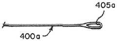
도 3b는 다른 예에 따른 루프 와이어의 일례의 평면도이다.
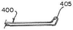
도 4는 대안적인 예에서 루프 와이어의 개구의 위를 향한 상태의 전방 확대 사시도이다.
도 5a는 의료 디바이스가 결합되고 루프 와이어가 고정된, 본 발명의 탈착 시스템의 일례의 분해도이다.
도 5b는 원위 튜브에 고정된 루프 와이어의 확대도이다.
도 6은 커플링과 중첩되는 근위 및 원위 튜브들의 평면도이다.
도 7은 커플링에 용접된 근위 및 원위 튜브들의 평면도이다.
도 8은 소형 튜브에서의 근위 용접부를 도시한다.
도 9는 탈착 시스템의 일례의 형광투시도를 도시한다.
도 10은 본 발명의 탈착 시스템을 형성하는 방법의 일례를 예시한다.
도 11a 내지 도 11d는 탈착된 의료 디바이스를 부분 단면으로 도시한다.
도 12는 압축 및 팽창 상태에 있는 원위 튜브의 일례의 측면도이다.
도 13은 탈착된 의료 디바이스의 일례의 전방측 사시도이다.The foregoing and further aspects of the invention are further discussed with reference to the following description, taken in conjunction with the accompanying drawings, in which like reference numerals designate like structural elements and features in the various drawings. The drawings are not necessarily to scale, emphasis instead being placed upon illustrating the principles of the invention. The drawings illustrate one or more embodiments of the inventive device by way of example only and not limitation.
1A is an exploded view of an example of a desorption system of the present invention in which the medical device is partially disengaged.
Figure 1B is an enlarged view of Figure 1A.
2 is an exploded view of an example of a desorption system of the present invention, in which a medical device is coupled;
3A is a side perspective view of an example of a loop wire according to an example.
3B is a plan view of an example of a loop wire according to another example.
4 is an enlarged front perspective view of the roof wire in an upwardly directed orientation in an alternative example;
5A is an exploded view of an example of a desorption system of the present invention in which a medical device is coupled and a loop wire is secured.
Figure 5b is an enlarged view of the loop wire secured to the distal tube.
Figure 6 is a top view of the proximal and distal tubes overlapping the coupling.
Figure 7 is a top view of the proximal and distal tubes welded to the coupling.
Figure 8 shows the proximal weld in a small tube.
Figure 9 shows a fluoroscopic view of an example of a desorption system.
Figure 10 illustrates an example of a method of forming the desorption system of the present invention.
Figures 11A-11D show a partially removed section of the detached medical device.
Figure 12 is a side view of an example of a distal tube in a compressed and expanded state.
Figure 13 is a front side perspective view of an example of a detached medical device.
도면은 본 발명에 따른 대체적으로 중공이거나 튜브형인 구조체를 도시한다. 본 명세서에 사용되는 바와 같이, 용어 "튜브형" 및 "튜브"는 넓게 해석될 것이며, 직원주인, 또는 그의 길이 전체에 걸쳐 단면이 엄밀하게 원주이거나 균일한 단면을 갖는 구조체로 제한되지 않는다. 예를 들어, 튜브형 구조체 또는 시스템은 대체적으로, 실질적으로 직원주형 구조체로서 도시되어 있다. 그러나, 튜브형 시스템은 본 발명의 범주로부터 벗어남이 없이 테이퍼진(tapered) 또는 만곡된 외부 표면을 가질 수 있다.The figure shows a structure which is generally hollow or tubular according to the invention. As used herein, the terms "tubular" and "tube" are to be construed broadly and are not intended to be limited to structures that have a strictly circumferential or uniform cross-section over the entire length or length of a staff member. For example, a tubular structure or system is generally shown as a substantially staff mold structure. However, the tubular system may have a tapered or curved outer surface without departing from the scope of the present invention.
도 1a, 도 1b, 및 도 2에 도시된 바와 같은, 본 발명의 탈착 시스템(10)의 일례는 세장형의 근위 전달 하이포튜브 조립체(100), 중간 커플링(200), 및 원위 전달 튜브(300)를 가질 수 있다. 이식가능 의료 디바이스(12)가 원위 전달 튜브(300)의 일 단부에 결합된다. 이식가능 의료 디바이스(12)는 색전 코일일 수 있지만, 사실상 어떠한 이식가능 의료 디바이스(12)도 본 발명에 따른 탈착 시스템(10)에 의해 전달 및 배치될 수 있는 것으로 이해될 것이다. 의료 디바이스(12)는 잠금 부재(140) 및 루프 와이어(400)를 사용하여 시스템에 결합된다. 의료 디바이스(12)는 결합 시스템(140, 400)과 인터페이싱하기 위한 잠금 부분(18)을 갖는다.An example of a
근위 전달 튜브(100)는 근위 단부 부분(102), 원위 단부 부분(104), 및 이들 사이의 가요성 부분(106)을 가질 수 있다. 근위 전달 튜브(100)는 내부에 축방향 루멘(108)을 형성한다. 근위 단부(102)는 축방향 루멘(108)을 따라서 더 작은 직경의 튜브(110)(도 5a, 도 6 내지 도 8 참조)와 결합한다. 원위 전달 튜브(300)는 근위 단부 부분(302), 원위 단부 부분(304), 및 이들 사이의 압축가능 부분(306)을 가질 수 있다. 일례에서, 압축가능 부분(306)은 원위 단부 부분(304)에 더 가까울 수 있고, 근위 단부 부분(302)과 압축가능 부분(306) 사이에 가요성 부분(305)이 있을 수 있다. 원위 전달 튜브(300)는 내부에 축방향 루멘(308)을 형성한다.The
전달 튜브(100, 300)는 스테인레스강과 같은 생체적합성 재료로 제조될 수 있다. 튜브(100, 300)는 전형적으로 직경이 약 0.010 인치 내지 약 0.018 인치일 수 있으며, 바람직한 튜브는 직경이 대략 0.0145 인치일 수 있다. 튜브 크기의 이러한 예는 신경혈관구조 내의 표적 위치, 전형적으로는 동맥류에 색전 코일을 전달 및 배치하기에 적합하다. 다른 재료로 구성된 상이한 크기의 튜브(100, 300)가 상이한 응용예에 유용할 수 있으며, 본 발명의 범주 내에 있다.The
가요성 부분(106, 305)은 전달 튜브(100, 300)가 굽혀지고 휘어지게 한다. 이는 카테터 및 사람 맥관구조를 통한 구불구불한 경로를 통해 시스템(10)을 추적하는 것을 돕는다. 가요성 부분(106, 306)에는 간섭 나선 절단부가 형성될 수 있다. 이러한 절단부는 갭이 굽힘을 허용하게 하지만, 일례에서, 나선 절단형 스프링으로서 작용하지는 않는다. 따라서, 굽혀지고 휘어질 수 있지만 압축되지는 않는다.The
압축가능 부분(306)은 연장 상태와 압축 상태 사이에서 축방향으로 조절가능하다. 바람직하게는, 압축가능 부분(306)은 레이저 절단 작업에 의해 형성되는, 튜브(300)의 나선 절단된 부분으로부터 형성된다. 그러나, 축방향 조절을 허용하는 임의의 다른 배열체(예컨대, 권취형 와이어 또는 나선형 리본)가 또한 본 발명에 따른 탈착 시스템과 함께 사용하기에 적합하다. 가장 바람직하게는, 압축가능 부분(306)은 휴지 상태에서 연장 상태에 있고, 달리 구속되지 않는 한, 압축 상태로부터 연장 상태로 자동적으로 또는 탄력적으로 복귀한다. 압축가능 부분(306)의 기능이 본 명세서에서 더 상세히 설명된다.The
커플링(200)의 일례는 근위 섹션(202), 원위 섹션(204), 이들 사이의 용접 밴드(206), 및 그 내부의 축방향 루멘(208)을 갖는다. 커플링(200)은 전달 튜브(100, 300) 둘을 가교(bridge)하고, 임상 사용 중에 전달 카테터 내의 탈착 시스템(10)의 정렬을 돕기 위해 방사선불투과성 마킹을 제공할 수 있다. 중간 커플링(200)의 일례는 마커 밴드 또는 코일 세그먼트일 수 있다.An example of
도 3a, 도 3b 및 도 4는 루프 와이어(400)의 예를 도시한다. 루프 와이어(400)는 비교적 작을 수 있어서, 일부 실시예에서는 모발의 두께를 갖고, 이는 우발적인 접촉으로부터의 손상을 방지하기 위해 원위 전달 튜브(300)의 원위 단부(304)에 의해 완전히 차폐되는 것이 바람직할 수 있다. 루프 와이어(400)는 도 3a에서와 같이 루프형인 세장형 와이어일 수 있다. 루프 와이어(400a)는 또한 도 3b에 도시된 바와 같이 개구(405)를 갖는 단일 세장형 와이어일 수 있다. 개구(405)는 루프 와이어(400a)를 절반으로 느슨하게 굽힘으로써 형성될 수 있다. 대안적인 예에서, 루프 와이어(400b)는 원위 부분에서 개구(405a)를 한정하는 플랫 리본(flat ribbon)을 포함하고, 개구(405a)는 이식가능 의료 디바이스(12)의 단부와 결합하기에 적합한 위를 향한 상태에 있을 수 있다. 루프 와이어(400, 400a, 400b)의 일례는, 그가 달리 구속되지 않는 경우에 실질적으로 편평한 상태로 복귀하도록 위를 향한 상태로 탄성 변형가능할 수 있다. 루프 와이어(400, 400a, 400b)는 니티놀(nitinol) 및 스테인레스강을 포함하는 다수의 재료들 중 임의의 재료로 형성될 수 있다.Figs. 3A, 3B and 4 show examples of the
탈착 시스템(10)을 로딩하기 위해, 잠금 부재(140)는 튜브(100, 300) 둘 모두 및 커플링(200)의 루멘(108, 208, 308) 내에 축방향으로 삽입된다. 루프 와이어(400)의 원위 단부(404)는 원위 튜브(300)의 근위 단부(302) 상에 위치된 앵커 부분(anchor portion)(310)을 통해 원위 전달 튜브(300) 내로 삽입되고 루멘(308)을 통과하여 원위 단부(304)로 넘어간다. 이어서 루프 와이어(404)의 원위 단부는 개구(405)를 형성하도록 루프형성될 수 있다. 개구(405)는 잠금 부분(18)을 통과하고, 잠금 부재(140)는 의료 디바이스(12)와 결합하도록 개구(405)를 통과한다. 도 1a 및 도 11a를 참조한다.Locking
루프 와이어(400)는 루프 와이어의 근위 단부(402)에서 팽팽하게 당겨지고, 계속되는 힘(F)은 압축가능 부분(306)을 압축한다. 압축 양은 의료 디바이스(12)가 원위 튜브(300)의 원위 단부(304) 상에 장착된 후에 루프 와이어(400)의 근위 단부(402)에 인가되는 힘(F)의 크기에 의해 제어될 수 있다. 도 2 및 도 11a는 장착된 의료 디바이스(12) 및 압축 상태의 원위 튜브(300)를 도시한다. 일단 원위 튜브(300)가 적절한 양만큼 압축되면, 루프 와이어(400)는, (근위 단부(402)와 원위 단부(404) 사이의) 와이어 용접점(406)에서, 원위 전달 튜브(300)의 앵커 부분(310)에 있는 또는 그에 가까이 있는 근위 단부(302)에 (즉, 압축가능 부분(306) 뒤에) 앵커 용접된다(408). 도 5a 및 도 5b를 참조한다. 원위 전달 튜브(300)의 압축 수준은 루프 와이어(400)를 앵커 용접부(408)에 의해 제 위치에 고정시키기 전에 루프 와이어(400) 상의 힘(F)의 크기를 가변시킴으로써 조정된다.The
도 6 및 도 7은 커플링(200)을 사용한 근위 전달 튜브(100)와 원위 전달 튜브(300)의 연결을 도시한다. 도 6은 근위 튜브(100)의 원위 단부(104)가 커플링(200)의 근위 단부(202)를 향해 당겨지고 그것과 중첩되는 것을 도시한다. 유사하게, 원위 튜브(300)의 근위 단부(302)는 커플링(200)의 원위 단부(204)를 향해 당겨지고 그것과 중첩된다. 본 예에서, 근위 및 원위 튜브들(100, 300)은 접촉하지 않지만, 용접 밴드(206)를 커플링(200) 상의 갭으로서 남겨둔다. 이어서, 2개의 튜브(100, 300)가 용접 밴드(206)에서 서로 원주방향으로 용접되어(210) 단일 디바이스(10)를 형성한다. 중간 커플링(200)은 전달 튜브(100, 300) 둘을 가교할 뿐만 아니라, 임상 사용 중에 시스템(10)을 전달 카테터(도시되지 않음)에 정렬시키기 위한 방사선불투과성 마킹을 제공한다.Figures 6 and 7 illustrate the connection of a
2개의 튜브와 커플링(100, 200, 300)의 중첩 및 용접 전에, (위에서 논의된 바와 같은) 잠금 부재(140)는 커플링 루멘(208) 및 근위 튜브 루멘(108)을 통하여 소형 튜브(110)로 통하여 당겨진다. 근위 튜브(100)의 근위 단부(102)에 반대편인 소형 튜브(110) 내의 근위 개구(112)에서, 잠금 부재(140)는 소형 튜브(110)에 용접된다(142). 이는 도 8에 도시되어 있다.The locking member 140 (as discussed above) is secured to the small tube (not shown) through the
도 9는 탈착 시스템(10)을 형광투시도로 도시한다. 커플링(200) 및 의료 디바이스(12)가 전형적으로 방사선불투과성 마킹으로 제조되거나 이를 갖는 것을 고려하면, 이는 커플링(200a) 또는 의료 디바이스(12a)와는 상이한 콘트라스트를 갖는 근위 튜브(100a) 및 원위 튜브(300a)의 관찰을 허용한다. 이는 디바이스(12a)가 해제되었을 때를 나타내는 시각적 피드백을 제공한다(아래에서 추가로 논의될 것이다).Figure 9 shows the
도 10은 탈착 시스템(10)을 조립하는 방법의 예를 예시한다. 본 방법은 원위 튜브(300) 상에 압축가능 부분(306)을 형성하는 단계(단계(1000)) 및 근위 튜브(100) 상에 가요성 부분(106)을 형성하는 단계(단계(1002))를 포함한다. 단계(1002)는 또한 원위 튜브(300) 상에 가요성 부분(305)을 형성하는 단계를 포함할 수 있다. 압축가능 부분(306)은, 압축될 수 있고 이어서 그의 비압축 상태로 신속하게 복귀할 수 있는 튜브를 형성하도록, 원위 튜브(300)를 나선 절단함으로써 또는 임의의 다른 수단에 의해 형성될 수 있다. 근위 튜브(100)의 가요성 부분(106)은 근위 튜브(100)의 가요성을 증가시키기 위해 간섭 절단될 수 있거나 임의의 다른 수단에 의할 수 있다. 일단 적어도 원위 튜브(300)가 준비되면, 의료 디바이스(12)는 결합 시스템(140, 400)과 결합될 수 있고(단계(1004)), 힘(F)이 결합 시스템(140, 400)에 인가되어 압축가능 부분(306)을 압축시킬 수 있다(단계(1006)). 여기서, 잠금 부재(140) 및 루프 와이어(400)를 결합 시스템으로서 사용하는 일례가 앞서 제공되어 있지만, 당업자는 결합 시스템(140, 400)이 의료 디바이스(12)로부터 결합해제될 때 해제될 압축가능 부분(306) 상에 해제가능 힘을 여전히 인가하면서 의료 디바이스(12)를 고정하기 위해 상이한 방법을 실현할 수 있다. 이어서, 결합 시스템(140, 400)의 섹션(406)이 원위 튜브(300)에 결합되어 압축가능 부분(306)의 압축 상태를 유지한다(단계(1008)). 결합 시스템(140, 400)의 일부분이 커플링(200) 및 근위 튜브(100)를 통해 꿰어진다(단계 1010). 원위 튜브(300)와 근위 튜브(100)는 커플링(200)을 사용하여 서로 연결된다(단계(1012)). 여기서, 본 예에서, 튜브(100, 300)의 단부(104, 302)는 커플링(200)과 중첩되고, 3개 모두는 함께 용접된다(210). 이어서, 결합 시스템(140, 400)의 단부(144)가 근위 튜브(100)의 근위 단부(102)에 연결되어(단계(1014)) 디바이스(10)를 완성할 수 있다.Figure 10 illustrates an example of a method of assembling the
도 11a 내지 도 11d를 참조하면, 의료 디바이스(12)의 탈착이 더욱 상세히 도시된다. 도 11a는 의료 디바이스(12)의 잠금 부분(18) 내로 잠금된 결합 시스템(140, 400)을 예시한다. 루프 와이어(400)의 개구(405)는 잠금 부분(18)을 통해 배치될 수 있다. 잠금 부재(140)가 개구(405)를 통해 놓일 때, 의료 디바이스(12)는 이제 고정된다. 힘(F)을 미리 적용하여 원위 튜브(300)를 압축 상태로 두었다. 도 11b는 의료 디바이스(12)를 위한 해제 시퀀스를 시작하기 위해 근위방향으로 끌어당겨지는 잠금 부재(140)를 도시한다. 도 11c는 잠금 부재(140)가 개구(405)를 빠져나가고 루프 와이어(400)로부터 자유롭도록 당겨진 순간을 도시한다. 루프 와이어(400)의 원위 단부(404)는 (위에서 논의된 바와 같이) 그의 미리형성된 형상으로 떨어지고/복귀되고, 잠금 부분(18)을 빠져나간다. 알 수 있는 바와 같이, 이제 탈착 시스템(10)에 의료 디바이스(12)를 유지하고 있는 것은 없다. 도 11d는 해제 시퀀스의 마지막을 도시한다. 여기서, 압축가능 부분(306)은 그의 원래 형상으로 팽창/복귀되었고 전방으로 "되튀었다". 원위 튜브(300)의 원위 단부(304)에 의해 의료 디바이스(12)에 탄성력(E)이 부여되어 그를 멀리 "밀어내서" 의료 디바이스(12)의 깨끗한 분리 및 전달을 보장한다.11A-11D, the detachment of the
도 12는 의료 디바이스(12) 없이 도시되어 있지만 압축가능 부분(306)이 축방향 길이가 압축 상태로 짧아진 원위 튜브(300)를 도시한다. 특히, 압축가능 부분(306)을 연장 상태로부터 압축 상태로 이동시킬 때 원위 튜브(300)가 축방향으로 단축되는 거리 "D"가 도시되어 있다. 이러한 압축은 축(A)을 따라서 일어날 수 있다. 도 13은 탈착 지점에서의 의료 디바이스(12)의 다른 도면을 도시한다. 잠금 부재(140)는 그가 루프 와이어(400)로부터 분리되도록 근위방향으로 당겨져서, 원위 압축 부분(306)이 팽창되고 의료 디바이스(12)를 전달 시스템(10)으로부터 더 분리시킴에 따라 의료 디바이스(12)가 분리되게 한다. 화살표("E")는 환자 내부의 표적 부위로의 깨끗한 분리 및 전달을 보장하기 위해 원위 단부(304)로부터 멀리 의료 디바이스(12)를 "밀어내는" 탄성력을 나타낸다. 탄성력(E)은 루멘(308)의 축(A)방향으로 작용하고, 동일한 축(A)을 따라 의료 디바이스(12)를 "밀어낸다"(도 8 및 도 12 참조).12 shows a
본 명세서에 포함된 설명은 본 발명의 실시예의 예이며, 어떠한 방식도 본 발명의 범주를 제한하고자 하는 것은 아니다. 본 명세서에 설명되는 바와 같이, 본 발명은, 다수의 구성, 다수의 강성 특성 및 이를 전달하기 위한 방법을 포함한, 혈관 폐색 디바이스를 위한 본 발명의 전달 및 해제 시스템의 많은 변형 및 변경을 고려한다. 또한, 해제 메커니즘의 재료 및 구성에 있어서 많은 가능한 변형이 있다. 이들 변형은 본 발명이 관련되는 당업자에게 명백할 것이며, 하기의 청구범위의 범주 내에 있는 것으로 의도된다.The descriptions included herein are examples of embodiments of the present invention and are not intended to limit the scope of the present invention in any way. As described herein, the present invention contemplates many variations and modifications of the delivery and release system of the present invention for vascular occlusion devices, including multiple configurations, multiple stiffness characteristics and methods for delivering them. In addition, there are many possible variations in the material and construction of the release mechanism. These modifications will be apparent to those skilled in the art to which the invention pertains and are intended to be within the scope of the following claims.
Claims (20)
Translated fromKorean대체적으로 중공인 원위 튜브로서, 상기 원위 튜브는
근위 단부;
원위 단부; 및
상기 근위 단부와 상기 원위 단부 사이의, 압축 상태로부터 연장 상태로 축방향으로 이동가능한, 상기 원위 튜브 자체의 압축가능 부분을 포함하는, 상기 원위 튜브;
근위 단부 및 원위 단부를 갖는 대체적으로 중공인 근위 튜브;
상기 원위 튜브의 근위 단부와 상기 근위 튜브의 원위 단부 사이에 배치되어, 상기 근위 튜브와 상기 원위 튜브를 연결하는 커플링;
상기 원위 튜브의 원위 단부에 결합되는 상기 이식가능 의료 디바이스와 결합하고 그를 배치하는 결합 시스템을 포함하고;
상기 결합 시스템은 상기 이식가능 의료 디바이스와 결합하는 경우 상기 압축가능 부분을 상기 압축 상태로 이동시키고,
상기 결합 시스템은 상기 이식가능 의료 디바이스를 배치하고 상기 압축가능 부분을 상기 연장 상태로 해제하는, 탈착 시스템.A detachment system for delivering an implantable medical device to a target location in a body vasculature,
As a generally hollow distal tube, the distal tube
A proximal end;
Distal end; And
The distal tube comprising a compressible portion of the distal tube itself movable between a proximal end and a distal end axially movable from a compressed state to an elongated state;
A generally hollow proximal tube having a proximal end and a distal end;
A coupling disposed between the proximal end of the distal tube and the distal end of the proximal tube for connecting the proximal tube and the distal tube;
And a coupling system for coupling to and placing the implantable medical device coupled to a distal end of the distal tube;
Wherein the coupling system moves the compressible portion into the compressed state when engaged with the implantable medical device,
Wherein the coupling system deploys the implantable medical device and releases the compressible portion into the extended state.
잠금 부재; 및
루프 와이어(loop wire)를 포함하고,
상기 루프 와이어가 상기 잠금 부재와 상호작용하여 상기 이식가능 의료 디바이스와 결합하는 경우, 상기 루프 와이어 상의 힘은 상기 압축가능 부분을 상기 압축 상태로 이동시키고,
상기 루프 와이어는 상기 결합 시스템을 제거가능하게 고정시키도록 상기 원위 튜브의 근위 단부에 용접되는, 탈착 시스템.3. The system of claim 2,
A locking member; And
Includes a loop wire,
Wherein when the loop wire interacts with the implantable medical device, the force on the loop wire moves the compressible portion to the compressed state,
Wherein the loop wire is welded to a proximal end of the distal tube to removably secure the coupling system.
상기 근위 튜브는 상기 커플링과 부분적으로 중첩하고,
상기 원위 튜브는 상기 커플링과 부분적으로 중첩하고,
상기 근위 튜브와 상기 원위 튜브 사이에서 상기 커플링 상에 형성된 갭(gap)은 상기 커플링을 상기 근위 튜브 및 상기 원위 튜브에 용접하기 위한 용접 밴드(weld band)를 포함하는, 탈착 시스템.The method according to claim 1,
The proximal tube partially overlapping the coupling,
The distal tube partially overlapping the coupling,
Wherein a gap formed on the coupling between the proximal tube and the distal tube includes a weld band for welding the coupling to the proximal tube and the distal tube.
상기 근위 튜브는 상기 근위 단부와 상기 원위 단부 사이에, 가요성인, 상기 근위 튜브 자체의 가요성 부분을 포함하고;
상기 원위 튜브는 상기 근위 단부와 상기 압축가능 부분 사이에, 가요성인, 상기 원위 튜브 자체의 가요성 부분을 포함하는, 탈착 시스템.The method according to claim 1,
Said proximal tube comprising a flexible portion of said proximal tube itself flexible between said proximal end and said distal end;
Wherein the distal tube comprises a flexible portion of the distal tube itself that is flexible between the proximal end and the compressible portion.
상기 근위 단부와 원위 단부 사이의 상기 원위 튜브 상에 압축가능 부분을 형성하는 단계;
상기 이식가능 의료 디바이스를 결합 시스템과 결합시키는 단계;
상기 압축가능 부분을 압축하도록 상기 결합 시스템에 힘을 인가하는 단계;
압축 상태를 유지하도록 상기 결합 시스템을 상기 원위 튜브에 고정시키는 단계;
상기 커플링을 사용하여 상기 원위 튜브와 상기 근위 튜브를 서로 연결하는 단계를 포함하는, 방법.A method of detachable implantable medical device comprising a hollow distal tube having a proximal end and a distal end, a hollow proximal end having a proximal end and a distal end, and a coupling,
Forming a compressible portion on the distal tube between the proximal and distal ends;
Coupling the implantable medical device with a mating system;
Applying a force to the coupling system to compress the compressible portion;
Securing the coupling system to the distal tube to maintain compression;
And coupling the distal tube and the proximal tube to each other using the coupling.
상기 결합시키는 단계는 상기 이식가능 의료 디바이스와 결합하기 위해 상기 잠금 부재와 함께 상기 루프 와이어를 사용하는 단계를 추가로 포함하고;
상기 인가하는 단계는 상기 압축가능 부분을 상기 압축 상태로 이동시키기 위해 상기 루프 와이어에 힘을 인가하는 단계를 추가로 포함하는, 방법.14. The system of claim 13, wherein the coupling system comprises a locking member and a loop wire,
Wherein the engaging further comprises using the loop wire with the locking member to engage the implantable medical device;
Wherein said applying further comprises applying a force to said loop wire to move said compressible portion to said compressed condition.
상기 잠금 부재 상에 힘을 인가하는 단계;
상기 이식가능 의료 디바이스와 결합해제하는 단계; 및
상기 압축가능 부분이 상기 연장 상태로 복귀하게 하는 단계를 추가로 포함하는, 방법.16. The method of claim 15,
Applying a force on the locking member;
Disengaging the implantable medical device; And
Further comprising causing the compressible portion to return to the extended condition.
상기 근위 튜브를 상기 커플링 위에 부분적으로 중첩시키는 단계;
상기 원위 튜브를 상기 커플링 위에 부분적으로 중첩시키는 단계;
용접 밴드를 포함하는 상기 근위 튜브와 상기 원위 튜브 사이의 상기 커플링 상에 갭을 형성하는 단계; 및
상기 용접 밴드에서 상기 커플링을 상기 근위 튜브 및 상기 원위 튜브에 용접하는 단계를 추가로 포함하는, 방법.13. The method of claim 12,
Partially overlapping the proximal tube over the coupling;
Partially overlapping the distal tube over the coupling;
Forming a gap on the coupling between the proximal tube and the distal tube including a welding band; And
Further comprising welding the coupling to the proximal tube and the distal tube in the welding band.
Applications Claiming Priority (2)
| Application Number | Priority Date | Filing Date | Title |
|---|---|---|---|
| US15/850,993US10806462B2 (en) | 2017-12-21 | 2017-12-21 | Implantable medical device detachment system with split tube and cylindrical coupling |
| US15/850,993 | 2017-12-21 |
Publications (1)
| Publication Number | Publication Date |
|---|---|
| KR20190076896Atrue KR20190076896A (en) | 2019-07-02 |
Family
ID=64746158
Family Applications (1)
| Application Number | Title | Priority Date | Filing Date |
|---|---|---|---|
| KR1020180167238ACeasedKR20190076896A (en) | 2017-12-21 | 2018-12-21 | Implantable medical device detachment system with split tube and cylindrical coupling |
Country Status (13)
| Country | Link |
|---|---|
| US (3) | US10806462B2 (en) |
| EP (1) | EP3501427B1 (en) |
| JP (1) | JP2019111339A (en) |
| KR (1) | KR20190076896A (en) |
| CN (1) | CN109998619B (en) |
| AU (1) | AU2018282416A1 (en) |
| BR (1) | BR102018076822A2 (en) |
| CA (1) | CA3028087A1 (en) |
| ES (1) | ES2802825T3 (en) |
| IL (1) | IL263847A (en) |
| MX (1) | MX2019000061A (en) |
| RU (1) | RU2018145325A (en) |
| TW (1) | TWI794378B (en) |
Families Citing this family (56)
| Publication number | Priority date | Publication date | Assignee | Title |
|---|---|---|---|---|
| US11076860B2 (en) | 2014-03-31 | 2021-08-03 | DePuy Synthes Products, Inc. | Aneurysm occlusion device |
| US11154302B2 (en) | 2014-03-31 | 2021-10-26 | DePuy Synthes Products, Inc. | Aneurysm occlusion device |
| US9918718B2 (en) | 2014-08-08 | 2018-03-20 | DePuy Synthes Products, Inc. | Embolic coil delivery system with retractable mechanical release mechanism |
| CN110545739A (en) | 2017-02-23 | 2019-12-06 | 德普伊新特斯产品公司 | aneurysm devices and delivery systems |
| US10806462B2 (en) | 2017-12-21 | 2020-10-20 | DePuy Synthes Products, Inc. | Implantable medical device detachment system with split tube and cylindrical coupling |
| US10905430B2 (en) | 2018-01-24 | 2021-02-02 | DePuy Synthes Products, Inc. | Aneurysm device and delivery system |
| US10806461B2 (en)* | 2018-04-27 | 2020-10-20 | DePuy Synthes Products, Inc. | Implantable medical device detachment system with split tube |
| US11058430B2 (en) | 2018-05-25 | 2021-07-13 | DePuy Synthes Products, Inc. | Aneurysm device and delivery system |
| US11596412B2 (en) | 2018-05-25 | 2023-03-07 | DePuy Synthes Products, Inc. | Aneurysm device and delivery system |
| US10939915B2 (en) | 2018-05-31 | 2021-03-09 | DePuy Synthes Products, Inc. | Aneurysm device and delivery system |
| US11051825B2 (en) | 2018-08-08 | 2021-07-06 | DePuy Synthes Products, Inc. | Delivery system for embolic braid |
| US11123077B2 (en) | 2018-09-25 | 2021-09-21 | DePuy Synthes Products, Inc. | Intrasaccular device positioning and deployment system |
| US11076861B2 (en) | 2018-10-12 | 2021-08-03 | DePuy Synthes Products, Inc. | Folded aneurysm treatment device and delivery method |
| US11439401B2 (en)* | 2018-11-16 | 2022-09-13 | Microvention, Inc. | Embolic coil |
| US12114863B2 (en)* | 2018-12-05 | 2024-10-15 | Microvention, Inc. | Implant delivery system |
| US11147562B2 (en) | 2018-12-12 | 2021-10-19 | DePuy Synthes Products, Inc. | Systems and methods for embolic implant detachment |
| US11406392B2 (en) | 2018-12-12 | 2022-08-09 | DePuy Synthes Products, Inc. | Aneurysm occluding device for use with coagulating agents |
| US11272939B2 (en) | 2018-12-18 | 2022-03-15 | DePuy Synthes Products, Inc. | Intrasaccular flow diverter for treating cerebral aneurysms |
| US11134953B2 (en) | 2019-02-06 | 2021-10-05 | DePuy Synthes Products, Inc. | Adhesive cover occluding device for aneurysm treatment |
| US11337706B2 (en) | 2019-03-27 | 2022-05-24 | DePuy Synthes Products, Inc. | Aneurysm treatment device |
| US11672542B2 (en) | 2019-05-21 | 2023-06-13 | DePuy Synthes Products, Inc. | Aneurysm treatment with pushable ball segment |
| US11413046B2 (en) | 2019-05-21 | 2022-08-16 | DePuy Synthes Products, Inc. | Layered braided aneurysm treatment device |
| US11278292B2 (en) | 2019-05-21 | 2022-03-22 | DePuy Synthes Products, Inc. | Inverting braided aneurysm treatment system and method |
| US11602350B2 (en) | 2019-12-05 | 2023-03-14 | DePuy Synthes Products, Inc. | Intrasaccular inverting braid with highly flexible fill material |
| US11607226B2 (en) | 2019-05-21 | 2023-03-21 | DePuy Synthes Products, Inc. | Layered braided aneurysm treatment device with corrugations |
| US10653425B1 (en) | 2019-05-21 | 2020-05-19 | DePuy Synthes Products, Inc. | Layered braided aneurysm treatment device |
| US11497504B2 (en) | 2019-05-21 | 2022-11-15 | DePuy Synthes Products, Inc. | Aneurysm treatment with pushable implanted braid |
| US11253265B2 (en) | 2019-06-18 | 2022-02-22 | DePuy Synthes Products, Inc. | Pull wire detachment for intravascular devices |
| US11207494B2 (en)* | 2019-07-03 | 2021-12-28 | DePuy Synthes Products, Inc. | Medical device delivery member with flexible stretch resistant distal portion |
| US20210346002A1 (en)* | 2019-07-03 | 2021-11-11 | DePuy Synthes Products, Inc. | Medical device delivery member with flexible stretch resistant distal portion |
| US11426174B2 (en) | 2019-10-03 | 2022-08-30 | DePuy Synthes Products, Inc. | Medical device delivery member with flexible stretch resistant mechanical release |
| US12376859B2 (en) | 2019-09-17 | 2025-08-05 | DePuy Synthes Products, Inc. | Embolic coil proximal connecting element and stretch resistant fiber |
| US11439403B2 (en)* | 2019-09-17 | 2022-09-13 | DePuy Synthes Products, Inc. | Embolic coil proximal connecting element and stretch resistant fiber |
| US11376013B2 (en)* | 2019-11-18 | 2022-07-05 | DePuy Synthes Products, Inc. | Implant delivery system with braid cup formation |
| US11457926B2 (en) | 2019-12-18 | 2022-10-04 | DePuy Synthes Products, Inc. | Implant having an intrasaccular section and intravascular section |
| US11457922B2 (en)* | 2020-01-22 | 2022-10-04 | DePuy Synthes Products, Inc. | Medical device delivery member with flexible stretch resistant distal portion |
| US11432822B2 (en)* | 2020-02-14 | 2022-09-06 | DePuy Synthes Products, Inc. | Intravascular implant deployment system |
| US20230062364A1 (en)* | 2020-02-16 | 2023-03-02 | Cardiac Success Ltd. | Flexible secure connection of multiple guidewires |
| US11951026B2 (en)* | 2020-06-30 | 2024-04-09 | DePuy Synthes Products, Inc. | Implantable medical device detachment system with flexible braid section |
| US12127743B2 (en) | 2020-09-23 | 2024-10-29 | DePuy Synthes Products, Inc. | Inverting braided aneurysm implant with dome feature |
| KR20220050060A (en) | 2020-10-15 | 2022-04-22 | 디퍼이 신테스 프로덕츠, 인코포레이티드 | Inverting braided aneurysm treatment system and method |
| EP4066752B1 (en) | 2021-03-31 | 2025-04-30 | DePuy Synthes Products, Inc. | Medical device delivery member with flexible stretch resistant distal portion |
| KR20230011880A (en) | 2021-07-14 | 2023-01-25 | 디퍼이 신테스 프로덕츠, 인코포레이티드 | Embolic coil proximal connecting element and stretch resistant fiber |
| US11998213B2 (en) | 2021-07-14 | 2024-06-04 | DePuy Synthes Products, Inc. | Implant delivery with modified detachment feature and pull wire engagement |
| US11751881B2 (en)* | 2021-11-26 | 2023-09-12 | DePuy Synthes Products, Inc. | Securement wire withstanding forces during deployment of implantable intravascular treatment device using a delivery and detachment system |
| US11937824B2 (en) | 2021-12-30 | 2024-03-26 | DePuy Synthes Products, Inc. | Implant detachment systems with a modified pull wire |
| US11844490B2 (en) | 2021-12-30 | 2023-12-19 | DePuy Synthes Products, Inc. | Suture linkage for inhibiting premature embolic implant deployment |
| US12011171B2 (en) | 2022-01-06 | 2024-06-18 | DePuy Synthes Products, Inc. | Systems and methods for inhibiting premature embolic implant deployment |
| US11937825B2 (en) | 2022-03-02 | 2024-03-26 | DePuy Synthes Products, Inc. | Hook wire for preventing premature embolic implant detachment |
| US12137915B2 (en) | 2022-03-03 | 2024-11-12 | DePuy Synthes Products, Inc. | Elongating wires for inhibiting premature implant detachment |
| US11937826B2 (en) | 2022-03-14 | 2024-03-26 | DePuy Synthes Products, Inc. | Proximal link wire for preventing premature implant detachment |
| WO2023175451A1 (en) | 2022-03-15 | 2023-09-21 | DePuy Synthes Products, Inc. | Semispherical braided aneurysm treatment system and method |
| WO2023199147A1 (en) | 2022-04-15 | 2023-10-19 | DePuy Synthes Products, Inc. | Medical device delivery member with positioning window |
| US20230397913A1 (en)* | 2022-06-14 | 2023-12-14 | DePuy Synthes Products, Inc. | Friction fit endovascular implant detachment mechanism |
| US12402886B2 (en) | 2022-06-23 | 2025-09-02 | DePuy Synthes Products, Inc. | Detachment indicator for implant deployment |
| US12396730B2 (en) | 2022-09-28 | 2025-08-26 | DePuy Synthes Products, Inc. | Braided implant with detachment mechanism |
Family Cites Families (264)
| Publication number | Priority date | Publication date | Assignee | Title |
|---|---|---|---|---|
| US3429408A (en) | 1967-04-25 | 1969-02-25 | Associated Spring Corp | Actuator sleeves for spring clutch |
| US5484409A (en) | 1989-08-25 | 1996-01-16 | Scimed Life Systems, Inc. | Intravascular catheter and method for use thereof |
| US5122136A (en) | 1990-03-13 | 1992-06-16 | The Regents Of The University Of California | Endovascular electrolytically detachable guidewire tip for the electroformation of thrombus in arteries, veins, aneurysms, vascular malformations and arteriovenous fistulas |
| US5108407A (en) | 1990-06-08 | 1992-04-28 | Rush-Presbyterian St. Luke's Medical Center | Method and apparatus for placement of an embolic coil |
| US5234437A (en) | 1991-12-12 | 1993-08-10 | Target Therapeutics, Inc. | Detachable pusher-vasoocclusion coil assembly with threaded coupling |
| US5636639A (en) | 1992-02-18 | 1997-06-10 | Symbiosis Corporation | Endoscopic multiple sample bioptome with enhanced biting action |
| US5263964A (en) | 1992-05-06 | 1993-11-23 | Coil Partners Ltd. | Coaxial traction detachment apparatus and method |
| US5350397A (en) | 1992-11-13 | 1994-09-27 | Target Therapeutics, Inc. | Axially detachable embolic coil assembly |
| US5250071A (en) | 1992-09-22 | 1993-10-05 | Target Therapeutics, Inc. | Detachable embolic coil assembly using interlocking clasps and method of use |
| US5382259A (en) | 1992-10-26 | 1995-01-17 | Target Therapeutics, Inc. | Vasoocclusion coil with attached tubular woven or braided fibrous covering |
| US5334210A (en) | 1993-04-09 | 1994-08-02 | Cook Incorporated | Vascular occlusion assembly |
| US5925059A (en) | 1993-04-19 | 1999-07-20 | Target Therapeutics, Inc. | Detachable embolic coil assembly |
| US5569221A (en)* | 1994-07-07 | 1996-10-29 | Ep Technologies, Inc. | Catheter component bond and method |
| US6273404B1 (en) | 1995-06-05 | 2001-08-14 | Scimed Life Systems, Inc. | Method of making monolithic hub and strain relief |
| US6168622B1 (en) | 1996-01-24 | 2001-01-02 | Microvena Corporation | Method and apparatus for occluding aneurysms |
| US5899935A (en) | 1997-08-04 | 1999-05-04 | Schneider (Usa) Inc. | Balloon expandable braided stent with restraint |
| US6203547B1 (en) | 1997-12-19 | 2001-03-20 | Target Therapeutics, Inc. | Vaso-occlusion apparatus having a manipulable mechanical detachment joint and a method for using the apparatus |
| US6113622A (en) | 1998-03-10 | 2000-09-05 | Cordis Corporation | Embolic coil hydraulic deployment system |
| US6835185B2 (en) | 1998-12-21 | 2004-12-28 | Micrus Corporation | Intravascular device deployment mechanism incorporating mechanical detachment |
| US6391037B1 (en) | 2000-03-02 | 2002-05-21 | Prodesco, Inc. | Bag for use in the intravascular treatment of saccular aneurysms |
| US6723108B1 (en) | 2000-09-18 | 2004-04-20 | Cordis Neurovascular, Inc | Foam matrix embolization device |
| US6623504B2 (en) | 2000-12-08 | 2003-09-23 | Scimed Life Systems, Inc. | Balloon catheter with radiopaque distal tip |
| EP1355693B1 (en) | 2001-01-10 | 2008-01-09 | Cordis Neurovascular, Inc. | Embolic coil introducer system |
| US6454780B1 (en) | 2001-06-21 | 2002-09-24 | Scimed Life Systems, Inc. | Aneurysm neck obstruction device |
| US20030009208A1 (en) | 2001-07-05 | 2003-01-09 | Precision Vascular Systems, Inc. | Torqueable soft tip medical device and method of usage |
| US8715312B2 (en) | 2001-07-20 | 2014-05-06 | Microvention, Inc. | Aneurysm treatment device and method of use |
| US8252040B2 (en) | 2001-07-20 | 2012-08-28 | Microvention, Inc. | Aneurysm treatment device and method of use |
| CA2468835A1 (en) | 2001-12-03 | 2003-06-12 | Ekos Corporation | Small vessel ultrasound catheter |
| US20030195553A1 (en) | 2002-04-12 | 2003-10-16 | Scimed Life Systems, Inc. | System and method for retaining vaso-occlusive devices within an aneurysm |
| US7608058B2 (en) | 2002-07-23 | 2009-10-27 | Micrus Corporation | Stretch resistant therapeutic device |
| US8425549B2 (en) | 2002-07-23 | 2013-04-23 | Reverse Medical Corporation | Systems and methods for removing obstructive matter from body lumens and treating vascular defects |
| US7208003B2 (en) | 2002-09-20 | 2007-04-24 | Cordis Neurovascular, Inc. | Reattachable introducer for a medical device deployment system |
| FR2853521B1 (en) | 2003-04-10 | 2005-12-02 | Claude Mialhe | DEVICE FOR EXPANDING A VESSEL AND INTRODUCING VASCULAR IMPLANT |
| US7371228B2 (en) | 2003-09-19 | 2008-05-13 | Medtronic Vascular, Inc. | Delivery of therapeutics to treat aneurysms |
| US8182544B2 (en) | 2003-10-08 | 2012-05-22 | Codman & Shurtleff, Inc. | Method for placing a medical agent into a vessel of the body |
| US9308382B2 (en) | 2004-06-10 | 2016-04-12 | Medtronic Urinary Solutions, Inc. | Implantable pulse generator systems and methods for providing functional and/or therapeutic stimulation of muscles and/or nerves and/or central nervous system tissue |
| US20060025801A1 (en) | 2004-07-30 | 2006-02-02 | Robert Lulo | Embolic device deployment system with filament release |
| US9655633B2 (en) | 2004-09-10 | 2017-05-23 | Penumbra, Inc. | System and method for treating ischemic stroke |
| WO2006052322A2 (en) | 2004-09-22 | 2006-05-18 | Guterman Lee R | Cranial aneurysm treatment arrangement |
| US20060089637A1 (en) | 2004-10-14 | 2006-04-27 | Werneth Randell L | Ablation catheter |
| DE602004010276D1 (en) | 2004-11-10 | 2008-01-03 | Creganna Technologies Ltd | Introducer catheter assembly for stents |
| US8562672B2 (en) | 2004-11-19 | 2013-10-22 | Medtronic, Inc. | Apparatus for treatment of cardiac valves and method of its manufacture |
| US20060116714A1 (en) | 2004-11-26 | 2006-06-01 | Ivan Sepetka | Coupling and release devices and methods for their assembly and use |
| US8425550B2 (en) | 2004-12-01 | 2013-04-23 | Boston Scientific Scimed, Inc. | Embolic coils |
| US7608089B2 (en) | 2004-12-22 | 2009-10-27 | Boston Scientific Scimed, Inc. | Vaso-occlusive device having pivotable coupling |
| US20060206139A1 (en) | 2005-01-19 | 2006-09-14 | Tekulve Kurt J | Vascular occlusion device |
| EP3266414B1 (en)* | 2005-05-12 | 2024-07-17 | Covidien LP | Implant delivery system with interlocked rx port orientation |
| US20060276833A1 (en) | 2005-06-02 | 2006-12-07 | Keith Balgobin | Stretch resistant embolic coil delivery system with spring assisted release mechanism |
| US7811305B2 (en) | 2005-06-02 | 2010-10-12 | Codman & Shurtleff, Inc. | Stretch resistant embolic coil delivery system with spring release mechanism |
| US20060276825A1 (en) | 2005-06-02 | 2006-12-07 | Vladimir Mitelberg | Stretch resistant embolic coil delivery system with mechanical release mechanism |
| US20060276830A1 (en) | 2005-06-02 | 2006-12-07 | Keith Balgobin | Stretch resistant embolic coil delivery system with mechanical release mechanism |
| US7708754B2 (en) | 2005-06-02 | 2010-05-04 | Codman & Shurtleff, Pc | Stretch resistant embolic coil delivery system with mechanical release mechanism |
| US7708755B2 (en) | 2005-06-02 | 2010-05-04 | Codman & Shurtleff Inc. | Stretch resistant embolic coil delivery system with combined mechanical and pressure release mechanism |
| US7819891B2 (en) | 2005-06-02 | 2010-10-26 | Codman & Shurtleff, Inc. | Stretch resistant embolic coil delivery system with spring release mechanism |
| US7367987B2 (en) | 2005-06-02 | 2008-05-06 | Cordis Neurovascular, Inc. | Stretch resistant embolic coil delivery system with mechanical release mechanism |
| US7371252B2 (en) | 2005-06-02 | 2008-05-13 | Cordis Neurovascular, Inc. | Stretch resistant embolic coil delivery system with mechanical release mechanism |
| US7799052B2 (en) | 2005-06-02 | 2010-09-21 | Codman & Shurtleff, Inc. | Stretch resistant embolic coil delivery system with mechanical release mechanism |
| US7985238B2 (en) | 2005-06-02 | 2011-07-26 | Codman & Shurtleff, Inc. | Embolic coil delivery system with spring wire release mechanism |
| US7371251B2 (en) | 2005-06-02 | 2008-05-13 | Cordis Neurovascular, Inc. | Stretch resistant embolic coil delivery system with mechanical release mechanism |
| US20060276826A1 (en) | 2005-06-02 | 2006-12-07 | Vladimir Mitelberg | Stretch resistant embolic coil delivery system with mechanical release mechanism |
| US7377932B2 (en) | 2005-06-02 | 2008-05-27 | Cordis Neurovascular, Inc. | Embolic coil delivery system with mechanical release mechanism |
| US7819892B2 (en) | 2005-06-02 | 2010-10-26 | Codman & Shurtleff, Inc. | Embolic coil delivery system with spring wire release mechanism |
| US9636115B2 (en) | 2005-06-14 | 2017-05-02 | Stryker Corporation | Vaso-occlusive delivery device with kink resistant, flexible distal end |
| EP2759276A1 (en) | 2005-06-20 | 2014-07-30 | Medtronic Ablation Frontiers LLC | Ablation catheter |
| US20070083132A1 (en) | 2005-10-11 | 2007-04-12 | Sharrow James S | Medical device coil |
| US8066036B2 (en) | 2005-11-17 | 2011-11-29 | Microvention, Inc. | Three-dimensional complex coil |
| US9757260B2 (en) | 2006-03-30 | 2017-09-12 | Medtronic Vascular, Inc. | Prosthesis with guide lumen |
| US7766933B2 (en) | 2006-03-31 | 2010-08-03 | Codman & Shurtleff, Inc. | Stretch resistant design for embolic coils with stabilization bead |
| US9615832B2 (en) | 2006-04-07 | 2017-04-11 | Penumbra, Inc. | Aneurysm occlusion system and method |
| US8777979B2 (en) | 2006-04-17 | 2014-07-15 | Covidien Lp | System and method for mechanically positioning intravascular implants |
| CA2655026C (en) | 2006-06-15 | 2016-08-02 | Microvention, Inc. | Embolization device constructed from expansible polymer |
| US8366720B2 (en) | 2006-07-31 | 2013-02-05 | Codman & Shurtleff, Inc. | Interventional medical device system having an elongation retarding portion and method of using the same |
| US8062325B2 (en) | 2006-07-31 | 2011-11-22 | Codman & Shurtleff, Inc. | Implantable medical device detachment system and methods of using the same |
| US7901444B2 (en) | 2006-09-29 | 2011-03-08 | Codman & Shurtleff, Inc. | Embolic coil delivery system with mechanical release mechanism |
| US8956381B2 (en) | 2006-11-20 | 2015-02-17 | Boston Scientific Scimed, Inc. | Mechanically detachable vaso-occlusive device |
| US20080306503A1 (en) | 2006-11-20 | 2008-12-11 | Boston Scientific Scimed, Inc. | Mechanically detachable vaso-occlusive device |
| US8926650B2 (en) | 2006-11-20 | 2015-01-06 | Boston Scientific Scimed, Inc. | Mechanically detachable vaso-occlusive device |
| US20080281350A1 (en) | 2006-12-13 | 2008-11-13 | Biomerix Corporation | Aneurysm Occlusion Devices |
| US8197442B2 (en) | 2007-04-27 | 2012-06-12 | Codman & Shurtleff, Inc. | Interventional medical device system having a slotted section and radiopaque marker and method of making the same |
| US8864789B2 (en) | 2007-04-27 | 2014-10-21 | DePuy Synthes Products, LLC | Interventional medical device system having a spiral section and radiopaque marker and method of making the same |
| US8221483B2 (en) | 2007-05-18 | 2012-07-17 | Stryker Corporation | Medical implant detachment systems and methods |
| DE102007038446A1 (en) | 2007-08-14 | 2009-02-19 | pfm Produkte für die Medizin AG | Embolisiereinrichtung |
| US20090099592A1 (en) | 2007-10-15 | 2009-04-16 | Boston Scientific Scimed, Inc. | Detachable Interlock Systems and Methods of Use |
| WO2009086208A2 (en) | 2007-12-21 | 2009-07-09 | Microvention, Inc. | Hydrogel filaments for biomedical uses |
| US8974518B2 (en) | 2008-03-25 | 2015-03-10 | Medtronic Vascular, Inc. | Eversible branch stent-graft and deployment method |
| EP2633823B1 (en) | 2008-04-21 | 2016-06-01 | Covidien LP | Braid-ball embolic devices and delivery systems |
| EP2192947A1 (en) | 2008-04-30 | 2010-06-09 | Medtronic, Inc. | Techniques for placing medical leads for electrical stimulation of nerve tissue |
| US20090312748A1 (en) | 2008-06-11 | 2009-12-17 | Johnson Kirk L | Rotational detachment mechanism |
| US8070694B2 (en) | 2008-07-14 | 2011-12-06 | Medtronic Vascular, Inc. | Fiber based medical devices and aspiration catheters |
| US8333796B2 (en) | 2008-07-15 | 2012-12-18 | Penumbra, Inc. | Embolic coil implant system and implantation method |
| US9232992B2 (en) | 2008-07-24 | 2016-01-12 | Aga Medical Corporation | Multi-layered medical device for treating a target site and associated method |
| US8721714B2 (en) | 2008-09-17 | 2014-05-13 | Medtronic Corevalve Llc | Delivery system for deployment of medical devices |
| CA2739603A1 (en) | 2008-10-13 | 2010-04-22 | Stryker Corporation | Vaso-occlusive coil delivery system |
| US8454578B2 (en) | 2009-02-18 | 2013-06-04 | AUST Development, LLC | Apparatus and methods for making coated liners and tubular devices including such liners |
| US9717500B2 (en) | 2009-04-15 | 2017-08-01 | Microvention, Inc. | Implant delivery system |
| TWI516244B (en) | 2009-04-20 | 2016-01-11 | 大塚醫療器材股份有限公司 | Delivery assembly for occlusion device using mechanical interlocking coupling mechanism |
| US8758423B2 (en) | 2009-06-18 | 2014-06-24 | Graftcraft I Goteborg Ab | Device and method for treating ruptured aneurysms |
| US9474532B2 (en) | 2009-09-09 | 2016-10-25 | Kaneka Corporation | Embolization coil |
| US9956100B2 (en) | 2009-09-15 | 2018-05-01 | Brightwater Medical, Inc. | Systems and methods for coupling and decoupling a catheter |
| US8911487B2 (en) | 2009-09-22 | 2014-12-16 | Penumbra, Inc. | Manual actuation system for deployment of implant |
| KR20110043799A (en) | 2009-10-16 | 2011-04-28 | 강호창 | Microcoil assembly |
| US9095342B2 (en) | 2009-11-09 | 2015-08-04 | Covidien Lp | Braid ball embolic device features |
| WO2011062844A1 (en) | 2009-11-18 | 2011-05-26 | Boston Scientific Scimed, Inc. | Delivery wire assembly for occlusive device delivery system |
| CN102188300B (en) | 2010-03-02 | 2014-05-28 | 上海微创医疗器械(集团)有限公司 | Aneurismal surgical device |
| AU2011240927B2 (en) | 2010-04-14 | 2015-07-16 | Microvention, Inc. | Implant delivery device |
| US8764811B2 (en) | 2010-04-20 | 2014-07-01 | Medtronic Vascular, Inc. | Controlled tip release stent graft delivery system and method |
| US8876878B2 (en) | 2010-07-23 | 2014-11-04 | Medtronic, Inc. | Attachment mechanism for stent release |
| US8616040B2 (en) | 2010-09-17 | 2013-12-31 | Medtronic Vascular, Inc. | Method of forming a drug-eluting medical device |
| US9039749B2 (en) | 2010-10-01 | 2015-05-26 | Covidien Lp | Methods and apparatuses for flow restoration and implanting members in the human body |
| WO2012088162A1 (en) | 2010-12-20 | 2012-06-28 | Microvention, Inc. | Polymer stents and methods of manufacture |
| US20120172913A1 (en) | 2010-12-30 | 2012-07-05 | Cook Medical Technologies Llc | Delivery of an embolization coil with an attacher |
| US20120283768A1 (en) | 2011-05-05 | 2012-11-08 | Sequent Medical Inc. | Method and apparatus for the treatment of large and giant vascular defects |
| US9486604B2 (en) | 2011-05-12 | 2016-11-08 | Medtronic, Inc. | Packaging and preparation tray for a delivery system |
| US8795241B2 (en) | 2011-05-13 | 2014-08-05 | Spiration, Inc. | Deployment catheter |
| WO2012158152A1 (en) | 2011-05-13 | 2012-11-22 | Spiration, Inc. | Deployment catheter |
| WO2012158668A1 (en) | 2011-05-17 | 2012-11-22 | Stryker Corporation | Method of fabricating an implantable medical device that includes one or more thin film polymer support layers |
| WO2012166467A1 (en) | 2011-05-27 | 2012-12-06 | Stryker Corporation | Assembly for percutaneously inserting an implantable medical device, steering the device to a target location and deploying the device |
| US9750565B2 (en) | 2011-09-30 | 2017-09-05 | Medtronic Advanced Energy Llc | Electrosurgical balloons |
| KR101315443B1 (en) | 2011-12-02 | 2013-10-07 | 강호창 | Micro-coil assembly |
| CA2867181C (en) | 2012-03-16 | 2020-08-11 | Microvention, Inc. | Stent and stent delivery device |
| US9833625B2 (en) | 2012-03-26 | 2017-12-05 | Medtronic, Inc. | Implantable medical device delivery with inner and outer sheaths |
| US9220906B2 (en)* | 2012-03-26 | 2015-12-29 | Medtronic, Inc. | Tethered implantable medical device deployment |
| US9717421B2 (en) | 2012-03-26 | 2017-08-01 | Medtronic, Inc. | Implantable medical device delivery catheter with tether |
| US9155540B2 (en) | 2012-03-30 | 2015-10-13 | DePuy Synthes Products, Inc. | Embolic coil detachment mechanism with heating element and kicker |
| US9242290B2 (en) | 2012-04-03 | 2016-01-26 | Medtronic Vascular, Inc. | Method and apparatus for creating formed elements used to make wound stents |
| US9549832B2 (en) | 2012-04-26 | 2017-01-24 | Medtronic Vascular, Inc. | Apparatus and methods for filling a drug eluting medical device via capillary action |
| US9700399B2 (en) | 2012-04-26 | 2017-07-11 | Medtronic Vascular, Inc. | Stopper to prevent graft material slippage in a closed web stent-graft |
| GB2501714B (en) | 2012-05-02 | 2014-05-07 | Cook Medical Technologies Llc | Implant delivery system |
| EP2668915A1 (en) | 2012-06-01 | 2013-12-04 | Acandis GmbH & Co. KG | System for delivering a stretch resistant vaso-occlusive device and a method of producing same |
| US10124087B2 (en)* | 2012-06-19 | 2018-11-13 | Covidien Lp | Detachable coupling for catheter |
| US9149190B2 (en) | 2012-07-17 | 2015-10-06 | Stryker Corporation | Notification system of deviation from predefined conditions |
| EP2882350B1 (en) | 2012-08-13 | 2019-09-25 | MicroVention, Inc. | Shaped removal device |
| US20140058435A1 (en) | 2012-08-21 | 2014-02-27 | Donald K. Jones | Implant delivery and release system |
| US9504476B2 (en) | 2012-10-01 | 2016-11-29 | Microvention, Inc. | Catheter markers |
| EP2906254B1 (en) | 2012-10-15 | 2020-01-08 | Microvention, Inc. | Polymeric treatment compositions |
| US10327781B2 (en) | 2012-11-13 | 2019-06-25 | Covidien Lp | Occlusive devices |
| US9539022B2 (en) | 2012-11-28 | 2017-01-10 | Microvention, Inc. | Matter conveyance system |
| WO2014089392A1 (en) | 2012-12-07 | 2014-06-12 | Medtronic, Inc. | Minimally invasive implantable neurostimulation system |
| US9943313B2 (en) | 2013-01-03 | 2018-04-17 | Empirilon Technology Llc | Detachable coil release system and handle assembly |
| US10342546B2 (en) | 2013-01-14 | 2019-07-09 | Microvention, Inc. | Occlusive device |
| US9949739B2 (en) | 2013-02-27 | 2018-04-24 | Microvention, Inc. | Integral wiping system and method |
| US9539382B2 (en) | 2013-03-12 | 2017-01-10 | Medtronic, Inc. | Stepped catheters with flow restrictors and infusion systems using the same |
| CN105228534B (en) | 2013-03-14 | 2018-03-30 | 斯瑞克公司 | Vaso-Occlusive Device Delivery System |
| BR112015021996A2 (en) | 2013-03-14 | 2017-07-18 | Incumedx Inc | implants, manufacturing methods and devices and methods for conducting implants to a patient's vascular disorder |
| WO2014150824A1 (en) | 2013-03-14 | 2014-09-25 | Stryker Corporation | Vaso-occlusive device delivery system |
| EP2967573B1 (en) | 2013-03-14 | 2021-04-21 | Stryker Corporation | Vaso-occlusive device delivery system |
| US9398966B2 (en) | 2013-03-15 | 2016-07-26 | Medtronic Vascular, Inc. | Welded stent and stent delivery system |
| BR112015023602A2 (en) | 2013-03-15 | 2017-07-18 | Microvention Inc | embolic protection device |
| WO2014151123A1 (en) | 2013-03-15 | 2014-09-25 | Microvention, Inc. | Multi-component obstruction removal system and method |
| US10736758B2 (en) | 2013-03-15 | 2020-08-11 | Covidien | Occlusive device |
| CN110169802B (en) | 2013-03-15 | 2022-07-08 | 柯惠有限合伙公司 | Delivery and detachment mechanism for vascular implants |
| US9662425B2 (en) | 2013-04-22 | 2017-05-30 | Stryker European Holdings I, Llc | Method for drug loading hydroxyapatite coated implant surfaces |
| US9445928B2 (en) | 2013-05-30 | 2016-09-20 | Medtronic Vascular, Inc. | Delivery system having a single handed deployment handle for a retractable outer sheath |
| US11291452B2 (en) | 2013-06-26 | 2022-04-05 | W. L. Gore & Associates, Inc. | Medical device deployment system |
| US10953193B2 (en) | 2013-07-16 | 2021-03-23 | Covidien Lp | Microcatheter with modified PTFE liner |
| US9662120B2 (en) | 2013-08-23 | 2017-05-30 | Cook Medical Technologies Llc | Detachable treatment device delivery system utilizing compression at attachment zone |
| US9675782B2 (en) | 2013-10-10 | 2017-06-13 | Medtronic Vascular, Inc. | Catheter pull wire actuation mechanism |
| US9955978B2 (en) | 2013-10-25 | 2018-05-01 | Medtronic Vascular, Inc. | Tissue compression device with multi-chamber bladder |
| KR102211335B1 (en) | 2013-12-20 | 2021-02-03 | 마이크로벤션, 인코포레이티드 | Device delivery system |
| EP3082939B1 (en) | 2013-12-20 | 2020-12-02 | MicroVention, Inc. | Delivery adapter |
| US9566072B2 (en) | 2013-12-27 | 2017-02-14 | Blockade Medical, LLC | Coil system |
| US9788839B2 (en)* | 2014-02-14 | 2017-10-17 | Cook Medical Technologies Llc | Stable screw-type detachment mechanism |
| WO2015157181A1 (en) | 2014-04-08 | 2015-10-15 | Stryker Corporation | Implant delivery system |
| US9629635B2 (en)* | 2014-04-14 | 2017-04-25 | Sequent Medical, Inc. | Devices for therapeutic vascular procedures |
| WO2015167997A1 (en) | 2014-04-30 | 2015-11-05 | Stryker Corporation | Implant delivery system and method of use |
| US9060777B1 (en) | 2014-05-28 | 2015-06-23 | Tw Medical Technologies, Llc | Vaso-occlusive devices and methods of use |
| US9668898B2 (en) | 2014-07-24 | 2017-06-06 | Medtronic Vascular, Inc. | Stent delivery system having dynamic deployment and methods of manufacturing same |
| CA2955953A1 (en) | 2014-07-25 | 2016-01-28 | Incumedx, Inc. | Covered embolic coils |
| US9918718B2 (en) | 2014-08-08 | 2018-03-20 | DePuy Synthes Products, Inc. | Embolic coil delivery system with retractable mechanical release mechanism |
| US9770577B2 (en) | 2014-09-15 | 2017-09-26 | Medtronic Xomed, Inc. | Pressure relief for a catheter balloon device |
| EP3193746A4 (en) | 2014-09-17 | 2018-10-31 | Metactive Medical, Inc. | Expandable body device and method of use |
| US9579484B2 (en) | 2014-09-19 | 2017-02-28 | Medtronic Vascular, Inc. | Sterile molded dispenser |
| GB2533087B (en) | 2014-12-08 | 2018-08-08 | Cook Medical Technologies Llc | Medical implant detachment mechanism and introducer assembly |
| CA2972620C (en) | 2015-01-20 | 2023-08-01 | Neurogami Medical, Inc. | Micrograft for the treatment of intracranial aneurysms and method for use |
| US11484319B2 (en) | 2015-01-20 | 2022-11-01 | Neurogami Medical, Inc. | Delivery system for micrograft for treating intracranial aneurysms |
| US10857012B2 (en) | 2015-01-20 | 2020-12-08 | Neurogami Medical, Inc. | Vascular implant |
| US10925611B2 (en) | 2015-01-20 | 2021-02-23 | Neurogami Medical, Inc. | Packaging for surgical implant |
| US9692557B2 (en) | 2015-02-04 | 2017-06-27 | Stryker European Holdings I, Llc | Apparatus and methods for administering treatment within a bodily duct of a patient |
| US10888331B2 (en) | 2015-02-10 | 2021-01-12 | Boston Scientific Scimed, Inc. | Active release of embolic coils |
| EP3266389A4 (en) | 2015-03-03 | 2018-11-21 | Kaneka Medix Corporation | Vascular embolization tool and production method therefor |
| US20160278782A1 (en) | 2015-03-26 | 2016-09-29 | Boston Scientific Scimed, Inc. | Embolic coil delivery system with easy-release knot |
| EP3291773A4 (en) | 2015-05-07 | 2019-05-01 | The Medical Research, Infrastructure, And Health Services Fund Of The Tel Aviv Medical Center | TEMPORARY INTERAURICULAR SHUNTS |
| US9717503B2 (en) | 2015-05-11 | 2017-08-01 | Covidien Lp | Electrolytic detachment for implant delivery systems |
| US10398874B2 (en) | 2015-05-29 | 2019-09-03 | Covidien Lp | Catheter distal tip configuration |
| US10307168B2 (en) | 2015-08-07 | 2019-06-04 | Terumo Corporation | Complex coil and manufacturing techniques |
| US10154905B2 (en) | 2015-08-07 | 2018-12-18 | Medtronic Vascular, Inc. | System and method for deflecting a delivery catheter |
| US10492938B2 (en) | 2015-08-11 | 2019-12-03 | Terumo Corporation | System and method for implant delivery |
| US20200147347A1 (en) | 2015-09-15 | 2020-05-14 | Orbusneich Medical Pte. Ltd. | Vascular re-entry catheter |
| EP3349669B1 (en) | 2015-09-18 | 2020-10-21 | Terumo Corporation | Vessel prosthesis |
| JP6816126B2 (en) | 2015-09-18 | 2021-01-20 | マイクロベンション インコーポレイテッドMicrovention, Inc. | Releasable delivery system |
| JP6854282B2 (en) | 2015-09-18 | 2021-04-07 | テルモ株式会社 | Pressable implant delivery system |
| CN113952095B (en) | 2015-09-18 | 2025-06-06 | 微仙美国有限公司 | Implant retention, detachment and delivery systems |
| CN108024821B (en) | 2015-09-21 | 2020-10-30 | 斯瑞克公司 | Embolectomy device |
| JP6591664B2 (en) | 2015-09-21 | 2019-10-16 | ストライカー コーポレイションStryker Corporation | Embolization removal device |
| US10172632B2 (en) | 2015-09-22 | 2019-01-08 | Medtronic Vascular, Inc. | Occlusion bypassing apparatus with a re-entry needle and a stabilization tube |
| WO2017062572A1 (en) | 2015-10-06 | 2017-04-13 | Boston Scientific Scimed, Inc. | Pusher arm and ball release mechanism for embolic coils |
| WO2017062383A1 (en) | 2015-10-07 | 2017-04-13 | Stryker Corporation | Multiple barrel clot removal devices |
| US10327791B2 (en) | 2015-10-07 | 2019-06-25 | Medtronic Vascular, Inc. | Occlusion bypassing apparatus with a re-entry needle and a distal stabilization balloon |
| US10786302B2 (en) | 2015-10-09 | 2020-09-29 | Medtronic, Inc. | Method for closure and ablation of atrial appendage |
| US9700322B2 (en) | 2015-10-14 | 2017-07-11 | Three Rivers Medical Inc. | Mechanical embolization delivery apparatus and methods |
| US10271873B2 (en) | 2015-10-26 | 2019-04-30 | Medtronic Vascular, Inc. | Sheathless guide catheter assembly |
| US11090055B2 (en) | 2015-10-30 | 2021-08-17 | Incumedx Inc. | Devices and methods for delivering an implant to a vascular disorder |
| WO2017087816A1 (en) | 2015-11-19 | 2017-05-26 | Penumbra, Inc. | Systems and methods for treatment of stroke |
| US10631946B2 (en) | 2015-11-30 | 2020-04-28 | Penumbra, Inc. | System for endoscopic intracranial procedures |
| EP3386580B1 (en) | 2015-12-09 | 2023-11-01 | Medtronic Vascular Inc. | Catheter with a lumen shaped as an identification symbol |
| US10159568B2 (en) | 2015-12-14 | 2018-12-25 | Medtronic, Inc. | Delivery system having retractable wires as a coupling mechanism and a deployment mechanism for a self-expanding prosthesis |
| US10500046B2 (en) | 2015-12-14 | 2019-12-10 | Medtronic, Inc. | Delivery system having retractable wires as a coupling mechanism and a deployment mechanism for a self-expanding prosthesis |
| WO2017117284A1 (en) | 2015-12-30 | 2017-07-06 | Stryker Corporation | Embolic devices and methods of manufacturing same |
| US20170189033A1 (en) | 2016-01-06 | 2017-07-06 | Microvention, Inc. | Occlusive Embolic Coil |
| US10070950B2 (en) | 2016-02-09 | 2018-09-11 | Medtronic Vascular, Inc. | Endoluminal prosthetic assemblies, and associated systems and methods for percutaneous repair of a vascular tissue defect |
| KR102837372B1 (en) | 2016-02-10 | 2025-07-24 | 마이크로벤션, 인코포레이티드 | Intravascular treatment site access |
| AU2017218115B2 (en) | 2016-02-10 | 2020-03-05 | Microvention, Inc. | Devices for vascular occlusion |
| US10188500B2 (en) | 2016-02-12 | 2019-01-29 | Medtronic Vascular, Inc. | Stent graft with external scaffolding and method |
| US10485579B2 (en) | 2016-02-25 | 2019-11-26 | Indian Wells Medical, Inc. | Steerable endoluminal punch |
| US20170258476A1 (en)* | 2016-03-08 | 2017-09-14 | Terumo Kabushiki Kaisha | Blood vessel treatment method |
| US20170281331A1 (en) | 2016-03-31 | 2017-10-05 | Medtronic Vascular, Inc. | Endoluminal prosthetic devices having fluid-absorbable compositions for repair of a vascular tissue defect |
| CN114432008A (en) | 2016-03-31 | 2022-05-06 | 美敦力瓦斯科尔勒公司 | Expandable introducer sheath with steering mechanism |
| US10695542B2 (en) | 2016-04-04 | 2020-06-30 | Medtronic Vascular, Inc. | Drug coated balloon |
| US10252024B2 (en) | 2016-04-05 | 2019-04-09 | Stryker Corporation | Medical devices and methods of manufacturing same |
| US10441407B2 (en) | 2016-04-12 | 2019-10-15 | Medtronic Vascular, Inc. | Gutter filling stent-graft and method |
| US9987122B2 (en) | 2016-04-13 | 2018-06-05 | Medtronic Vascular, Inc. | Iliac branch device and method |
| US10010403B2 (en) | 2016-04-18 | 2018-07-03 | Medtronic Vascular, Inc. | Stent-graft prosthesis and method of manufacture |
| US20170304097A1 (en) | 2016-04-21 | 2017-10-26 | Medtronic Vascular, Inc. | Stent-graft delivery system having an inner shaft component with a loading pad or covering on a distal segment thereof for stent retention |
| WO2017189591A1 (en) | 2016-04-25 | 2017-11-02 | Stryker Corporation | Inverting mechanical thrombectomy apparatuses and methods of use in the vasculature |
| US10940294B2 (en) | 2016-04-25 | 2021-03-09 | Medtronic Vascular, Inc. | Balloon catheter including a drug delivery sheath |
| US10517711B2 (en) | 2016-04-25 | 2019-12-31 | Medtronic Vascular, Inc. | Dissection prosthesis system and method |
| EP3448276B1 (en) | 2016-04-25 | 2020-03-04 | Stryker Corporation | Clot-engulfing mechanical thrombectomy apparatuses |
| EP3590446B1 (en) | 2016-04-25 | 2021-01-06 | Stryker Corporation | Anti-jamming and macerating thrombectomy apparatuses |
| US10406011B2 (en) | 2016-04-28 | 2019-09-10 | Medtronic Vascular, Inc. | Implantable medical device delivery system |
| US11147952B2 (en) | 2016-04-28 | 2021-10-19 | Medtronic Vascular, Inc. | Drug coated inflatable balloon having a thermal dependent release layer |
| US10191615B2 (en) | 2016-04-28 | 2019-01-29 | Medtronic Navigation, Inc. | Method and apparatus for image-based navigation |
| FR3050635A1 (en) | 2016-05-02 | 2017-11-03 | Univ Strasbourg | INFLATABLE AND DETACHABLE BALLOON FOR USE IN A BODY CAVITY, TREATMENT NECESSARY AND DRAINING METHOD THEREOF |
| US10292844B2 (en) | 2016-05-17 | 2019-05-21 | Medtronic Vascular, Inc. | Method for compressing a stented prosthesis |
| US9968360B2 (en) | 2016-05-31 | 2018-05-15 | Spartan Micro, Inc. | Systems and methods for delivering intravascular implants |
| US10285710B2 (en) | 2016-06-01 | 2019-05-14 | DePuy Synthes Products, Inc. | Endovascular detachment system with flexible distal end and heater activated detachment |
| US10786659B2 (en) | 2016-06-01 | 2020-09-29 | Microvention, Inc. | Reinforced balloon catheter |
| CN109561903B (en) | 2016-06-03 | 2021-07-27 | 斯瑞克公司 | Flip thrombectomy device |
| WO2017223396A1 (en) | 2016-06-24 | 2017-12-28 | Boston Scientific Scimed, Inc. | Stretch-resistant coil |
| US10420563B2 (en) | 2016-07-08 | 2019-09-24 | Neurogami Medical, Inc. | Delivery system insertable through body lumen |
| US10646689B2 (en) | 2016-07-29 | 2020-05-12 | Cephea Valve Technologies, Inc. | Mechanical interlock for catheters |
| WO2018022186A1 (en) | 2016-07-29 | 2018-02-01 | Wallaby Medical, Inc. | Implant delivery systems and methods |
| WO2018053314A1 (en) | 2016-09-16 | 2018-03-22 | Greg Mirigian | Occlusive implants with fiber-based release structures |
| US10292851B2 (en) | 2016-09-30 | 2019-05-21 | DePuy Synthes Products, Inc. | Self-expanding device delivery apparatus with dual function bump |
| US10258492B2 (en) | 2017-03-03 | 2019-04-16 | Cook Medical Technologies Llc | Prosthesis delivery system with axially collapsible sheath |
| US11116509B2 (en) | 2017-11-10 | 2021-09-14 | Avantec Vascular Corporation | System and method for delivering an embolic device |
| US10806462B2 (en) | 2017-12-21 | 2020-10-20 | DePuy Synthes Products, Inc. | Implantable medical device detachment system with split tube and cylindrical coupling |
| WO2019152775A1 (en) | 2018-02-01 | 2019-08-08 | Boston Scientific Scimed, Inc. | Medical device release system |
| US11305095B2 (en) | 2018-02-22 | 2022-04-19 | Scientia Vascular, Llc | Microfabricated catheter having an intermediate preferred bending section |
| SG11202008410YA (en) | 2018-03-07 | 2020-09-29 | Innovative Cardiovascular Solutions Llc | Embolic protection device |
| US10806461B2 (en) | 2018-04-27 | 2020-10-20 | DePuy Synthes Products, Inc. | Implantable medical device detachment system with split tube |
| US10631791B2 (en) | 2018-06-25 | 2020-04-28 | Caption Health, Inc. | Video clip selector for medical imaging and diagnosis |
| WO2020093012A1 (en) | 2018-11-01 | 2020-05-07 | Terumo Corporation | Occlusion systems |
| US11147562B2 (en) | 2018-12-12 | 2021-10-19 | DePuy Synthes Products, Inc. | Systems and methods for embolic implant detachment |
| US20210196281A1 (en) | 2018-12-12 | 2021-07-01 | DePuy Synthes Products, Inc. | Systems and methods for embolic implant detachment |
| US10765843B2 (en) | 2018-12-31 | 2020-09-08 | J.D. Franco & Co., Llc | Intravascular devices, systems, and methods to address eye disorders |
| US11812970B2 (en) | 2019-01-17 | 2023-11-14 | Endostream Medical Ltd. | Vascular-malformation implant system |
| US11253265B2 (en) | 2019-06-18 | 2022-02-22 | DePuy Synthes Products, Inc. | Pull wire detachment for intravascular devices |
| US11207494B2 (en) | 2019-07-03 | 2021-12-28 | DePuy Synthes Products, Inc. | Medical device delivery member with flexible stretch resistant distal portion |
| US11426174B2 (en) | 2019-10-03 | 2022-08-30 | DePuy Synthes Products, Inc. | Medical device delivery member with flexible stretch resistant mechanical release |
| EP4033998B1 (en) | 2019-09-24 | 2025-05-14 | Boston Scientific Scimed, Inc. | Medical device release system |
| US11382634B2 (en) | 2019-12-18 | 2022-07-12 | Avantec Vascular Corporation | Embolic device suited for ease of delivery and placement |
| US11457922B2 (en) | 2020-01-22 | 2022-10-04 | DePuy Synthes Products, Inc. | Medical device delivery member with flexible stretch resistant distal portion |
| US11931041B2 (en) | 2020-05-12 | 2024-03-19 | Covidien Lp | Devices, systems, and methods for the treatment of vascular defects |
| US11998213B2 (en) | 2021-07-14 | 2024-06-04 | DePuy Synthes Products, Inc. | Implant delivery with modified detachment feature and pull wire engagement |
- 2017
- 2017-12-21USUS15/850,993patent/US10806462B2/enactiveActive
- 2018
- 2018-12-19ILIL263847Apatent/IL263847A/enunknown
- 2018-12-19EPEP18214030.1Apatent/EP3501427B1/enactiveActive
- 2018-12-19ESES18214030Tpatent/ES2802825T3/enactiveActive
- 2018-12-19CACA3028087Apatent/CA3028087A1/ennot_activeAbandoned
- 2018-12-20AUAU2018282416Apatent/AU2018282416A1/ennot_activeAbandoned
- 2018-12-20RURU2018145325Apatent/RU2018145325A/ennot_activeApplication Discontinuation
- 2018-12-20JPJP2018238053Apatent/JP2019111339A/enactivePending
- 2018-12-21KRKR1020180167238Apatent/KR20190076896A/ennot_activeCeased
- 2018-12-21BRBR102018076822-0Apatent/BR102018076822A2/ennot_activeApplication Discontinuation
- 2018-12-21CNCN201811571900.6Apatent/CN109998619B/enactiveActive
- 2018-12-21TWTW107146490Apatent/TWI794378B/enactive
- 2019
- 2019-01-07MXMX2019000061Apatent/MX2019000061A/enunknown
- 2020
- 2020-10-07USUS17/064,907patent/US11826051B2/enactiveActive
- 2023
- 2023-06-29USUS18/215,969patent/US20230338038A1/enactivePending
Also Published As
| Publication number | Publication date |
|---|---|
| US20210015484A1 (en) | 2021-01-21 |
| AU2018282416A1 (en) | 2019-07-11 |
| IL263847A (en) | 2019-03-31 |
| CA3028087A1 (en) | 2019-06-21 |
| ES2802825T3 (en) | 2021-01-21 |
| MX2019000061A (en) | 2019-08-29 |
| TWI794378B (en) | 2023-03-01 |
| US20230338038A1 (en) | 2023-10-26 |
| CN109998619A (en) | 2019-07-12 |
| US20190192162A1 (en) | 2019-06-27 |
| JP2019111339A (en) | 2019-07-11 |
| US10806462B2 (en) | 2020-10-20 |
| US11826051B2 (en) | 2023-11-28 |
| RU2018145325A (en) | 2020-06-22 |
| TW201936123A (en) | 2019-09-16 |
| BR102018076822A2 (en) | 2019-06-25 |
| CN109998619B (en) | 2024-10-01 |
| EP3501427B1 (en) | 2020-04-29 |
| EP3501427A1 (en) | 2019-06-26 |
Similar Documents
| Publication | Publication Date | Title |
|---|---|---|
| KR20190076896A (en) | Implantable medical device detachment system with split tube and cylindrical coupling | |
| JP7362290B2 (en) | Implantable Medical Device Removal System with Split Tube | |
| US20240115267A1 (en) | Embolic coil delivery system with retractable mechanical release mechanism | |
| JP7532117B2 (en) | Medical device delivery member having a flexible stretch-resistant distal portion - Patents.com | |
| KR101746087B1 (en) | Connection of an endovascular intervention device to a manipulation member | |
| US20060025802A1 (en) | Embolic coil delivery system with U-shaped fiber release mechanism | |
| US20220054136A1 (en) | Implantable medical device detachment system with split tube and cylindrical coupling | |
| US20220338878A1 (en) | Mechanical detachment system with a lever structure for deployment of endovascular devices | |
| EP4147650A1 (en) | Implantable medical device detachment system with split tube and cylindrical coupling | |
| KR102873210B1 (en) | Implantable medical device detachment system with split tube and method of detaching implantable medical device | |
| EP4205670B1 (en) | Suture linkage for inhibiting premature embolic implant deployment | |
| US20220339014A1 (en) | Mechanical detachment system with a hold-release structure for deployment of endovascular devices |
Legal Events
| Date | Code | Title | Description |
|---|---|---|---|
| PA0109 | Patent application | Patent event code:PA01091R01D Comment text:Patent Application Patent event date:20181221 | |
| PG1501 | Laying open of application | ||
| A201 | Request for examination | ||
| PA0201 | Request for examination | Patent event code:PA02012R01D Patent event date:20211220 Comment text:Request for Examination of Application Patent event code:PA02011R01I Patent event date:20181221 Comment text:Patent Application | |
| E902 | Notification of reason for refusal | ||
| PE0902 | Notice of grounds for rejection | Comment text:Notification of reason for refusal Patent event date:20230925 Patent event code:PE09021S01D | |
| E902 | Notification of reason for refusal | ||
| PE0902 | Notice of grounds for rejection | Comment text:Notification of reason for refusal Patent event date:20240529 Patent event code:PE09021S01D | |
| E601 | Decision to refuse application | ||
| PE0601 | Decision on rejection of patent | Patent event date:20240801 Comment text:Decision to Refuse Application Patent event code:PE06012S01D |