KR20190076656A - Mobile terminal - Google Patents
Mobile terminalDownload PDFInfo
- Publication number
- KR20190076656A KR20190076656AKR1020170178628AKR20170178628AKR20190076656AKR 20190076656 AKR20190076656 AKR 20190076656AKR 1020170178628 AKR1020170178628 AKR 1020170178628AKR 20170178628 AKR20170178628 AKR 20170178628AKR 20190076656 AKR20190076656 AKR 20190076656A
- Authority
- KR
- South Korea
- Prior art keywords
- piezoelectric actuator
- sensor
- vibration
- grip
- mobile terminal
- Prior art date
- Legal status (The legal status is an assumption and is not a legal conclusion. Google has not performed a legal analysis and makes no representation as to the accuracy of the status listed.)
- Abandoned
Links
Images


Classifications
- H—ELECTRICITY
- H04—ELECTRIC COMMUNICATION TECHNIQUE
- H04M—TELEPHONIC COMMUNICATION
- H04M1/00—Substation equipment, e.g. for use by subscribers
- H04M1/02—Constructional features of telephone sets
- H04M1/0202—Portable telephone sets, e.g. cordless phones, mobile phones or bar type handsets
- H04M1/026—Details of the structure or mounting of specific components
- G—PHYSICS
- G06—COMPUTING OR CALCULATING; COUNTING
- G06F—ELECTRIC DIGITAL DATA PROCESSING
- G06F3/00—Input arrangements for transferring data to be processed into a form capable of being handled by the computer; Output arrangements for transferring data from processing unit to output unit, e.g. interface arrangements
- G06F3/01—Input arrangements or combined input and output arrangements for interaction between user and computer
- G06F3/016—Input arrangements with force or tactile feedback as computer generated output to the user
- G—PHYSICS
- G06—COMPUTING OR CALCULATING; COUNTING
- G06F—ELECTRIC DIGITAL DATA PROCESSING
- G06F21/00—Security arrangements for protecting computers, components thereof, programs or data against unauthorised activity
- G06F21/30—Authentication, i.e. establishing the identity or authorisation of security principals
- G06F21/31—User authentication
- G06F21/32—User authentication using biometric data, e.g. fingerprints, iris scans or voiceprints
- G—PHYSICS
- G06—COMPUTING OR CALCULATING; COUNTING
- G06F—ELECTRIC DIGITAL DATA PROCESSING
- G06F3/00—Input arrangements for transferring data to be processed into a form capable of being handled by the computer; Output arrangements for transferring data from processing unit to output unit, e.g. interface arrangements
- G06F3/01—Input arrangements or combined input and output arrangements for interaction between user and computer
- G06F3/03—Arrangements for converting the position or the displacement of a member into a coded form
- G06F3/041—Digitisers, e.g. for touch screens or touch pads, characterised by the transducing means
- G06F3/044—Digitisers, e.g. for touch screens or touch pads, characterised by the transducing means by capacitive means
- H—ELECTRICITY
- H04—ELECTRIC COMMUNICATION TECHNIQUE
- H04M—TELEPHONIC COMMUNICATION
- H04M1/00—Substation equipment, e.g. for use by subscribers
- H04M1/02—Constructional features of telephone sets
- H04M1/0202—Portable telephone sets, e.g. cordless phones, mobile phones or bar type handsets
- H04M1/026—Details of the structure or mounting of specific components
- H04M1/0266—Details of the structure or mounting of specific components for a display module assembly
- H—ELECTRICITY
- H04—ELECTRIC COMMUNICATION TECHNIQUE
- H04M—TELEPHONIC COMMUNICATION
- H04M19/00—Current supply arrangements for telephone systems
- H04M19/02—Current supply arrangements for telephone systems providing ringing current or supervisory tones, e.g. dialling tone or busy tone
- H04M19/04—Current supply arrangements for telephone systems providing ringing current or supervisory tones, e.g. dialling tone or busy tone the ringing-current being generated at the substations
- H—ELECTRICITY
- H04—ELECTRIC COMMUNICATION TECHNIQUE
- H04M—TELEPHONIC COMMUNICATION
- H04M2250/00—Details of telephonic subscriber devices
- H04M2250/12—Details of telephonic subscriber devices including a sensor for measuring a physical value, e.g. temperature or motion
Landscapes
- Engineering & Computer Science (AREA)
- General Engineering & Computer Science (AREA)
- Theoretical Computer Science (AREA)
- Physics & Mathematics (AREA)
- General Physics & Mathematics (AREA)
- Computer Security & Cryptography (AREA)
- Signal Processing (AREA)
- Human Computer Interaction (AREA)
- Software Systems (AREA)
- Computer Hardware Design (AREA)
- Telephone Function (AREA)
- User Interface Of Digital Computer (AREA)
- Telephone Set Structure (AREA)
Abstract
Description
Translated fromKorean본 발명은 압전 액추에이터를 구비하는 이동 단말기에 관한 것이다.The present invention relates to a mobile terminal having a piezoelectric actuator.
전자 장치는 이동 가능여부에 따라 이동 단말기(mobile/portable terminal) 및 고정 단말기(stationary terminal)로 나뉠 수 있다. 다시 이동 단말기는 사용자의 직접 휴대 가능 여부에 따라 휴대(형) 단말기(handheld terminal) 및 거치형 단말기(vehicle mounted terminal)로 나뉠 수 있다.An electronic device can be divided into a mobile / portable terminal and a stationary terminal depending on whether the electronic device is movable or not. The mobile terminal can be divided into a handheld terminal and a vehicle mounted terminal according to whether the user can directly carry the mobile terminal.
이와 같은 전자 장치(또는 단말기)는 기술의 발전에 따라 다양한 기능을 가지게 되었다. 예를 들어, 전자 장치는 사진이나 동영상의 촬영, 음악이나 동영상 파일의 재생, 게임, 방송의 수신 등의 복합적인 기능들을 갖춘 멀티미디어 기기(Multimedia player) 형태로 구현되고 있다. 나아가 전자 장치의 기능 지지 및 증대를 위해, 전자 장치의 구조적인 부분 및/또는 소프트웨어적인 부분을 개량하는 것이 고려될 수 있다.Such electronic devices (or terminals) have various functions as the technology develops. For example, an electronic device is implemented in the form of a multimedia device having multiple functions such as photographing and photographing of a moving picture, reproduction of a music or video file, reception of a game, and reception of a broadcast. Further, for functional support and enhancement of the electronic device, it may be considered to improve the structural and / or software portion of the electronic device.
최근에는 사용자에게 다양한 햅틱 피드백을 제공하고자 하는 연구가 이루어지고 있다. 햅틱 피드백의 대표적인 예로는 진동 전달이 있는데, 기존에는 일반적으로 진동을 발생시키기 위하여 선형 공진 액추에이터(LRA: Linear Resonant Actuator)를 이용하였다. 그러나, 선형 공진 액추에이터는 후술하는 압전 액추에이터보다는 응답속도가 느리고 동작 주파수의 범위가 넓지 않다는 한계가 있다.Recently, research has been conducted to provide users with various haptic feedbacks. A typical example of haptic feedback is vibration transmission. In the past, a linear resonant actuator (LRA) was used to generate vibration in general. However, the linear resonance actuator has a limitation that the response speed is slower than the piezoelectric actuator described later and the range of the operating frequency is not wide.
압전 액추에이터는 전기장에 의해 순간적으로 크기나 모양이 변하는 특성이 있는 압전 소자를 이용하여 구동되는 액추에이터이다. 압전 액추에이터는 응답속도가 매우 빠르고 동작 주파수가 광범위하여, 다양한 촉각 효과를 구현할 수 있다는 장점이 있다. 뿐만 아니라, 압전 액추에이터는 크기나 두께 등의 제약이 없어 선형 공진 액추에이터에 비하여 형태적으로 자유롭다는 이점이 있다.A piezoelectric actuator is an actuator that is driven by a piezoelectric element having a characteristic in which an instantaneous change in size or shape is caused by an electric field. Piezoelectric actuators have the advantage of being able to realize various tactile effects because of their high response speed and wide operating frequency. In addition, there is an advantage that the piezoelectric actuator is free in form and size compared with the linear resonance actuator because there is no restriction on the size or the thickness.
한편, 최근에는 보안성 향상을 위하여 지문인식 센서를 구비하는 이동 단말기가 일반화되고 있다. 이전에는 지문인식 센서가 베젤 부분에 배치되는 것이 일반적이었는데, 대화면을 구현하기 위하여 베젤이 거의 없는 이동 단말기가 출시되면서, 지문인식 센서를 디스플레이부 아래에 위치시키고자 하는 연구가 진행되고 있다.Meanwhile, in recent years, a mobile terminal equipped with a fingerprint recognition sensor has been popularized to improve security. Previously, a fingerprint sensor was generally placed on the bezel. Research has been conducted to place the fingerprint sensor under the display unit with the introduction of a mobile terminal with few bezels to implement a large screen.
본 발명의 첫 번째 목적은, 지문인식 센서가 디스플레이부의 아래에 위치하는 구조에서, 지문인식 과정에서의 진동 피드백이 사용자에게 효과적으로 제공될 수 있는 구조를 제공하기 위한 것이다.A first object of the present invention is to provide a structure in which, in a structure in which a fingerprint recognition sensor is located below a display unit, vibration feedback in a fingerprint recognition process can be effectively provided to a user.
본 발명의 두 번째 목적은, 이동 단말기의 후면에 배치되는 후방키를 통하여 지문인식 및 진동 피드백의 제공이 가능한 구조를 제공하기 위한 것이다.A second object of the present invention is to provide a structure capable of providing fingerprint recognition and vibration feedback through a rear key disposed on the rear surface of a mobile terminal.
본 발명의 세 번째 목적은, 압전 액추에이터를 포함한 복수의 진동소자와 기타 다른 센서(터치 센서, 그립 센서)를 이용한 다양한 유저 인터페이스를 제공하기 위한 것이다.A third object of the present invention is to provide various user interfaces using a plurality of vibration elements including a piezoelectric actuator and other sensors (touch sensors, grip sensors).
본 발명의 첫 번째 목적을 달성하기 위하여, 본 발명의 이동 단말기는 윈도우; 상기 윈도우의 배면에 배치되어 상기 윈도우를 통하여 시각 정보를 출력하고, 유기발광다이오드를 구비하는 디스플레이; 상기 디스플레이의 배면에 배치되며, 상기 윈도우 상의 사용자의 지문을 감지하는 지문인식 센서; 및 중공부를 구비하는 환형으로 형성되어 상기 중공부에 상기 지문인식 센서를 수용하고, 상기 윈도우로 진동을 전달하거나 상기 윈도우에 가해지는 힘을 감지하도록 구성되는 압전 액추에이터를 포함한다.In order to achieve the first object of the present invention, a mobile terminal of the present invention includes a window; A display disposed on a back surface of the window and outputting time information through the window, the display having an organic light emitting diode; A fingerprint recognition sensor disposed on a back surface of the display and sensing fingerprints of a user on the window; And a piezoelectric actuator that is formed in an annular shape having a hollow portion to accommodate the fingerprint recognition sensor in the hollow portion and to transmit vibration to the window or to sense a force applied to the window.
상기 이동 단말기는, 상기 디스플레이의 배면에 부착되는 완충시트; 및 상기 완충시트의 배면에 부착되어 상기 디스플레이에서 발생한 열을 분산시키는 써멀시트를 더 포함하며, 상기 지문인식 센서는 상기 디스플레이의 배면에 부착되고, 상기 압전 액추에이터는 상기 써멀시트의 배면에 부착될 수 있다.The mobile terminal comprising: a buffer sheet attached to a back surface of the display; And a thermal sheet attached to the back surface of the buffer sheet to disperse heat generated in the display, wherein the fingerprint sensor is attached to the back surface of the display, and the piezoelectric actuator is attached to the back surface of the thermal sheet have.
상기 이동 단말기는, 상기 써멀시트와 상기 압전 액추에이터 사이에 배치되고, 환형으로 형성되어 내측에 상기 지문인식 센서를 수용하며, 상기 압전 액추에이터와 전기적으로 연결되는 연성회로를 더 포함할 수 있다.The mobile terminal may further include a flexible circuit disposed between the thermal sheet and the piezoelectric actuator, the flexible circuit being formed in an annular shape and accommodating the fingerprint recognition sensor inside, and electrically connected to the piezoelectric actuator.
상기 압전 액추에이터의 상면에는 제1 및 제2전극이 상기 지문인식 센서를 사이에 두고 양측에 각각 배치되며, 상기 연성회로는 상기 제1 및 제2전극과 전기적으로 연결되고 상기 써멀시트의 배면에 부착될 수 있다.The first and second electrodes are disposed on both sides of the piezoelectric actuator on both sides of the fingerprint recognition sensor, the flexible circuit is electrically connected to the first and second electrodes, and is attached to the back surface of the thermal sheet .
상기 이동 단말기는, 상기 압전 액추에이터의 일측 상면에 구비되는 제1 및 제2전극과 전기적으로 연결되는 연성회로; 및 환형으로 형성되어 내측에 상기 지문인식 센서를 수용하고, 상기 연성회로를 덮도록 배치되며, 상기 써멀시트의 배면에 부착되는 진동전달부재를 더 포함할 수 있다.The mobile terminal includes: a flexible circuit electrically connected to first and second electrodes provided on one upper surface of the piezoelectric actuator; And a vibration transmitting member that is formed in an annular shape and accommodates the fingerprint recognition sensor on the inside and is disposed to cover the flexible circuit and attached to the back surface of the thermal sheet.
상기 진동전달부재는, 상기 연성회로와 상기 써멀시트 사이에 배치되는 제1부분; 및 상기 제1부분에서 연장되어 상기 압전 액추에이터와 상기 써멀시트 사이에 배치되고, 상기 제1부분보다 증가된 두께를 가지는 제2부분을 포함하며, 상기 제1 및 제2부분은 환형으로 형성되어 내측에 상기 지문인식 센서를 수용할 수 있다.Wherein the vibration transmitting member comprises: a first portion disposed between the flexible circuit and the thermal sheet; And a second portion extending from the first portion and disposed between the piezoelectric actuator and the thermal sheet, the second portion having an increased thickness over the first portion, the first and second portions being formed in an annular shape, The fingerprint recognition sensor can be accommodated in the fingerprint sensor.
상기 진동전달부재는, 상기 제2부분에서 하방으로 연장되어, 상기 압전 액추에이터가 지지되는 프레임에 지지되는 지지부분을 더 포함할 수 있다.The vibration transmitting member may further include a support portion extending downward from the second portion and supported by a frame on which the piezoelectric actuator is supported.
상기 연성회로와 상기 지지부분은 상기 지문인식 센서를 사이에 두고 양측에 각각 배치될 수 있다.The flexible circuit and the support portion may be disposed on both sides of the fingerprint recognition sensor.
상기 이동 단말기는, 상기 지문인식 센서와 전기적으로 연결되어 상기 지문인식 센서로부터 일방향으로 연장되는 연성인쇄회로기판을 더 포함하며, 상기 연성인쇄회로기판은 오버랩되는 상기 압전 액추에이터의 상면에 구비되는 제1 및 제2전극과 전기적으로 연결될 수 있다.The mobile terminal further includes a flexible printed circuit board electrically connected to the fingerprint recognition sensor and extending from the fingerprint recognition sensor in one direction, wherein the flexible printed circuit board has a first And the second electrode.
상기 이동 단말기는, 상기 지문인식 센서에 의해 감지된 지문에 근거하여 상기 압전 액추에이터로 인가되는 전압을 제어하는 제어부를 더 포함할 수 있다.The mobile terminal may further include a controller for controlling a voltage applied to the piezoelectric actuator based on the fingerprint sensed by the fingerprint sensor.
상기 이동 단말기는, 상기 지문인식 센서에 의해 감지된 지문과, 상기 압전 액추에이터에 의해 감지된 상기 윈도우에 가해지는 힘에 근거하여, 상기 디스플레이의 구동을 제어하는 제어부를 더 포함할 수 있다.The mobile terminal may further include a controller for controlling driving of the display based on a fingerprint sensed by the fingerprint recognition sensor and a force applied to the window sensed by the piezoelectric actuator.
아울러, 본 발명의 두 번째 목적을 달성하기 위하여, 본 발명의 이동 단말기는, 전면으로 시각 정보를 출력하는 디스플레이부; 사용자의 지문을 감지하는 지문인식 센서를 구비하고, 후면에 배치되어 두께 방향으로 상기 디스플레이부와 오버랩되는 후방키; 상기 후방키의 배면에 배치되어, 상기 후방키로 진동을 전달하거나 상기 후방키에 가해지는 힘을 감지하도록 구성되는 압전 액추에이터; 및 상기 압전 액추에이터를 지지하고, 상기 압전 액추에이터의 배면과의 사이에서 캐비티를 형성하도록 상면에 움푹 들어간 리세스부가 형성된 프레임을 포함한다.In order to achieve the second object of the present invention, a mobile terminal of the present invention includes: a display unit for outputting time information to a front side; A rear key having a fingerprint sensor for detecting a fingerprint of a user and disposed on the rear surface and overlapped with the display unit in a thickness direction; A piezoelectric actuator disposed on a rear surface of the rear key, the piezoelectric actuator being configured to transmit a vibration to the rear key or to sense a force applied to the rear key; And a frame having a recessed portion formed on an upper surface thereof for supporting the piezoelectric actuator and forming a cavity between the piezoelectric actuator and the back surface of the piezoelectric actuator.
상기 이동 단말기는, 상기 후방키와 상기 압전 액추에이터 사이에 배치되어, 상기 압전 액추에이터의 제1 및 제2전극과 전기적으로 연결되는 연성회로를 더 포함할 수 있다.The mobile terminal may further include a flexible circuit disposed between the rear key and the piezoelectric actuator and electrically connected to the first and second electrodes of the piezoelectric actuator.
또한, 본 발명의 세 번째 목적을 달성하기 위하여, 본 발명의 이동 단말기는, 유기발광다이오드를 구비하는 터치 스크린; 지문인식 센서; 압전 액추에이터; 및 상기 터치 스크린과 상기 압전 액추에이터의 구동을 제어하는 제어부를 포함하며, 상기 제어부는, 상기 터치 스크린이 오프된 상태에서, 상기 터치 스크린의 기설정된 영역에 가해지는 힘을 상기 압전 액추에이터를 이용하여 감지하는 단계; 상기 기설정된 영역을 온 상태로 전환하는 단계; 상기 기설정된 영역 상의 사용자의 지문을 감지하는 단계; 및 상기 지문인식 센서에 의해 감지된 지문에 근거하여 상기 터치 스크린의 구동을 제어하는 단계를 포함한다.According to another aspect of the present invention, there is provided a mobile terminal including: a touch screen including an organic light emitting diode; Fingerprint recognition sensor; Piezoelectric Actuator; And a control unit for controlling driving of the touch screen and the piezoelectric actuator, wherein the controller detects a force applied to a predetermined area of the touch screen by using the piezoelectric actuator when the touch screen is off, ; Switching the predetermined area to an on state; Detecting a fingerprint of a user on the predetermined area; And controlling the driving of the touch screen based on the fingerprint sensed by the fingerprint recognition sensor.
상기 제어부는, 상기 터치 스크린이 오프된 상태에서, 상기 터치 스크린의 기설정된 영역에 그래픽 객체를 표시하는 단계를 더 포함할 수 있다.The controller may further include displaying the graphic object in a predetermined area of the touch screen when the touch screen is off.
상기 제어부는, 상기 지문인식 센서에 의해 감지된 지문에 근거하여 상기 압전 액추에이터로 인가되는 전압을 제어하는 단계를 더 포함할 수 있다.The control unit may further include a step of controlling a voltage applied to the piezoelectric actuator based on the fingerprint sensed by the fingerprint recognition sensor.
본 발명의 세 번째 목적은, 시각 정보를 출력하는 터치 스크린; 복수의 진동소자; 및 상기 터치 스크린과 상기 복수의 진동소자의 구동을 제어하는 제어부를 포함하며, 상기 제어부는, 상기 터치 스크린에 대한 터치 위치를 감지하는 단계; 감지된 터치 위치에 근거하여, 상기 복수의 진동소자 중 어느 하나를 구동하여 진동을 발생시키는 단계; 상기 터치의 이동을 감지하는 단계; 및 이동된 터치 위치에 근거하여, 진동을 발생시키는 진동소자를 다른 진동소자로 변경하는 단계를 포함하는 이동 단말기에 의해서도 달성될 수 있다.A third object of the present invention is to provide a touch screen which outputs visual information; A plurality of vibration elements; And a controller for controlling driving of the touch screen and the plurality of vibration elements, wherein the controller includes: sensing a touch position of the touch screen; Driving one of the plurality of vibration elements to generate vibration based on the sensed touch position; Sensing movement of the touch; And changing the vibrating element that generates vibration to another vibrating element, based on the moved touch position.
상기 제어부는 상기 복수의 진동소자 중 터치 위치에 인접한 진동소자를 구동시킬 수 있다.The control unit may drive the vibration element adjacent to the touch position among the plurality of vibration elements.
상기 제어부는 터치 위치와 상기 터치 위치에 인접한 진동소자 간의 거리에 근거하여, 상기 인접한 진동소자에 인가되는 전류를 제어할 수 있다.The controller may control a current applied to the adjacent vibration element based on a touch position and a distance between the vibration element adjacent to the touch position.
상기 복수의 진동소자 중 적어도 하나는 압전 액추에이터가 될 수 있다.At least one of the plurality of vibration elements may be a piezoelectric actuator.
본 발명의 세 번째 목적은, 복수의 진동소자; 단말기 바디에 대한 그립을 감지하는 그립 센서부; 및 상기 복수의 진동소자의 구동을 제어하는 제어부를 포함하며, 상기 제어부는, 상기 그립 센서부를 이용하여 상기 단말기 바디에 대한 그립을 감지하는 단계; 및 검출된 그립 위치에 따라 복수의 진동 패턴 중 하나가 출력되도록 복수의 진동소자 각각의 구동을 제어하는 단계를 포함하는 이동 단말기에 의해서도 달성될 수 있다.A third object of the present invention is to provide a vibration device comprising: a plurality of vibration elements; A grip sensor unit for sensing a grip on the terminal body; And a controller for controlling driving of the plurality of vibrating elements, wherein the controller detects a grip on the terminal body using the grip sensor unit; And controlling the driving of each of the plurality of vibration elements so that one of the plurality of vibration patterns is outputted in accordance with the detected grip position.
상기 그립 센서부는 상기 단말기 바디의 좌우측에 각각 배치되는 제1그립 센서와 제2그립 센서를 포함하며, 상기 제어부는, 상기 제1 및 제2그립 센서에 대한 그립이 모두 검출되면, 상기 복수의 진동소자 중 어느 하나를 구동시키고, 상기 제1 및 제2그립 센서 중 어느 하나에 대한 그립이 검출되면, 상기 복수의 진동소자를 모두 구동시킬 수 있다.Wherein the grip sensor unit includes a first grip sensor and a second grip sensor disposed at left and right sides of the terminal body, respectively, and when the grips for the first and second grip sensors are all detected, When any one of the elements is driven and a grip for any one of the first and second grip sensors is detected, all of the plurality of vibration elements can be driven.
본 발명의 세 번째 목적은, 시각 정보를 출력하는 디스플레이부; 복수의 진동소자; 단말기 바디에 대한 그립을 감지하는 그립 센서부; 및 상기 복수의 진동소자의 구동을 제어하는 제어부를 포함하며, 상기 제어부는, 상기 그립 센서부를 이용하여 상기 단말기 바디에 대한 그립을 감지하는 단계; 상기 그립의 이동을 감지하는 단계; 및 이동된 그립 위치에 근거하여, 상기 복수의 진동소자 중 어느 하나를 구동하여 진동을 발생시키는 단계를 포함하는 이동 단말기에 의해서도 달성될 수 있다.A third object of the present invention is to provide a display device which outputs visual information; A plurality of vibration elements; A grip sensor unit for sensing a grip on the terminal body; And a controller for controlling driving of the plurality of vibrating elements, wherein the controller detects a grip on the terminal body using the grip sensor unit; Sensing movement of the grip; And generating a vibration by driving one of the plurality of vibration elements based on the moved grip position.
상기 제어부는 상기 복수의 진동소자 중 감지된 그립 위치에 인접한 진동소자를 구동시킬 수 있다.The control unit may drive the vibration element adjacent to the grip position sensed among the plurality of vibration elements.
상기 제어부는 이동된 그립 위치에 근거하여, 상기 인접한 진동소자에 인가되는 전류를 제어할 수 있다.The control unit may control a current applied to the adjacent vibration element based on the moved grip position.
상술한 해결수단을 통해 얻게 되는 본 발명의 효과는 다음과 같다.Effects of the present invention obtained through the above-mentioned solution are as follows.
첫째, OLED 디스플레이를 포함하는 디스플레이부의 배면에 지문인식 센서가 배치되고, 압전 액추에이터가 지문인식 센서를 감싸는 환형으로 형성되어 디스플레이부의 배면에 부착됨으로써, 지문인식 과정에서의 진동 피드백이 사용자에게 효과적으로 제공될 수 있다.First, a fingerprint recognition sensor is disposed on the back surface of the display unit including the OLED display, and the piezoelectric actuator is formed in an annular shape surrounding the fingerprint recognition sensor and attached to the back surface of the display unit, thereby effectively providing vibration feedback in the fingerprint recognition process to the user .
특히, 압전 액추에이터에 구비되는 전극의 배치 형태 및 상기 전극과 연성회로의 연결 구조 별로 압전 액추에이터와 디스플레이부 간의 진동(내지는 힘) 전달 구조를 달리함으로써, 진동 피드백이 디스플레이부로 명확하게 전달될 수 있고, 사용자가 디스플레이부를 가압하는 힘이 압전 액추에이터로 명확하게 전달될 수 있다.Particularly, by changing the arrangement of the electrodes provided in the piezoelectric actuator and the structure for transmitting vibration (or force) between the piezoelectric actuator and the display unit for each connection structure of the electrodes and the flexible circuit, the vibration feedback can be clearly transmitted to the display unit, The force that the user presses the display portion can be clearly communicated to the piezoelectric actuator.
둘째, 후방키에 지문인식 센서가 내장되고, 후방키의 배면에 압전 액추에이터가 배치되며, 압전 액추에이터를 지지하는 프레임에 압전 액추에이터의 진동을 위한 리세스부가 형성됨으로써, 후방키를 통한 지문인식 및 진동 피드백의 제공이 가능한 이동 단말기가 구현될 수 있다.Second, a fingerprint recognition sensor is incorporated in the rear key, a piezoelectric actuator is disposed on the rear surface of the rear key, and a recess for vibrating the piezoelectric actuator is formed on the frame supporting the piezoelectric actuator, A mobile terminal capable of providing feedback can be implemented.
셋째, 압전 액추에이터를 포함한 복수의 진동소자와 기타 다른 센서(터치 센서, 그립 센서)를 통하여, 보다 다양한 유저 인터페이스가 제공될 수 있으며, 사용자의 감성을 충족시키는 이동 단말기가 제공될 수 있다.Thirdly, a variety of user interfaces can be provided through a plurality of vibration devices including a piezoelectric actuator and other sensors (touch sensors, grip sensors), and a mobile terminal that meets user's emotions can be provided.
도 1은 본 발명과 관련된 이동 단말기를 설명하기 위한 블록도.
도 2 및 도 3은 본 발명의 일 실시 예에 따른 이동 단말기를 서로 다른 방향에서 바라본 개념도들.
도 4의 (a)는 본 발명의 이동 단말기에 적용되는 압전 액추에이터의 일 예를 보인 평면도이고, (b)는 (a)에 도시된 압전 액추에이터가 지문인식 센서와 함께 배치된 구조를 보인 개념도.
도 5의 (a)는 본 발명의 이동 단말기에 적용되는 압전 액추에이터의 다른 일 예를 보인 평면도이고, (b)는 (a)에 도시된 압전 액추에이터가 지문인식 센서와 함께 배치된 구조를 보인 개념도.
도 6은 본 발명의 이동 단말기에 적용되는 압전 액추에이터가 지문인식 센서의 연성인쇄회로기판에 전기적으로 연결되는 구조를 설명하기 위한 개념도.
도 7은 본 발명의 이동 단말기에 적용되는 조작유닛에 압전 액추에이터가 적용된 구조를 보인 개념도.
도 8은 압전 액추에이터의 힘-전압 특성을 설명하기 위한 개념도.
도 9는 압전 액추에이터와 지문인식 센서를 이용한 이동 단말기의 제어 방법의 일 예를 설명하기 위한 개념도.
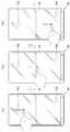
도 10은 복수의 진동소자를 이용한 이동 단말기의 제어 방법의 일 예를 설명하기 위한 개념도.
도 11은 그립센서와 복수의 진동소자를 이용한 이동 단말기의 제어 방법의 일 예를 설명하기 위한 개념도.
도 12는 그립센서와 복수의 진동소자를 이용한 이동 단말기의 제어 방법의 다른 일 예를 설명하기 위한 개념도.1 is a block diagram illustrating a mobile terminal according to the present invention;
FIG. 2 and FIG. 3 are conceptual diagrams illustrating mobile terminals according to an embodiment of the present invention. FIG.
FIG. 4A is a plan view showing an example of a piezoelectric actuator applied to a mobile terminal according to the present invention, and FIG. 4B is a conceptual view showing a structure in which the piezoelectric actuator shown in FIG.
FIG. 5A is a plan view showing another example of a piezoelectric actuator applied to a mobile terminal of the present invention, FIG. 5B is a conceptual view showing a structure in which the piezoelectric actuator shown in FIG. .
6 is a conceptual diagram illustrating a structure in which a piezoelectric actuator applied to a mobile terminal of the present invention is electrically connected to a flexible printed circuit board of a fingerprint recognition sensor.
7 is a conceptual view showing a structure in which a piezoelectric actuator is applied to an operation unit applied to a mobile terminal of the present invention.
8 is a conceptual diagram for explaining force-voltage characteristics of a piezoelectric actuator;
9 is a conceptual diagram for explaining an example of a control method of a mobile terminal using a piezoelectric actuator and a fingerprint recognition sensor.
10 is a conceptual diagram for explaining an example of a control method of a mobile terminal using a plurality of vibration elements.
11 is a conceptual diagram for explaining an example of a control method of a mobile terminal using a grip sensor and a plurality of vibration elements.
12 is a conceptual diagram for explaining another example of a control method of a mobile terminal using a grip sensor and a plurality of vibration elements.
이하, 첨부된 도면을 참조하여 본 명세서에 개시된 실시 예를 상세히 설명하되, 도면 부호에 관계없이 동일하거나 유사한 구성요소는 동일한 참조 번호를 부여하고 이에 대한 중복되는 설명은 생략하기로 한다. 이하의 설명에서 사용되는 구성요소에 대한 접미사 "모듈" 및 "부"는 명세서 작성의 용이함만이 고려되어 부여되거나 혼용되는 것으로서, 그 자체로 서로 구별되는 의미 또는 역할을 갖는 것은 아니다. 또한, 본 명세서에 개시된 실시 예를 설명함에 있어서 관련된 공지 기술에 대한 구체적인 설명이 본 명세서에 개시된 실시 예의 요지를 흐릴 수 있다고 판단되는 경우 그 상세한 설명을 생략한다. 또한, 첨부된 도면은 본 명세서에 개시된 실시 예를 쉽게 이해할 수 있도록 하기 위한 것일 뿐, 첨부된 도면에 의해 본 명세서에 개시된 기술적 사상이 제한되지 않으며, 본 발명의 사상 및 기술 범위에 포함되는 모든 변경, 균등물 내지 대체물을 포함하는 것으로 이해되어야 한다.Hereinafter, embodiments of the present invention will be described in detail with reference to the accompanying drawings, wherein like reference numerals are used to designate identical or similar elements, and redundant description thereof will be omitted. The suffix "module" and " part "for the components used in the following description are given or mixed in consideration of ease of specification, and do not have their own meaning or role. In the following description of the embodiments of the present invention, a detailed description of related arts will be omitted when it is determined that the gist of the embodiments disclosed herein may be blurred. It is to be understood that both the foregoing general description and the following detailed description are exemplary and explanatory and are intended to provide further explanation of the invention as claimed. , ≪ / RTI > equivalents, and alternatives.
제1, 제2 등과 같이 서수를 포함하는 용어는 다양한 구성요소들을 설명하는데 사용될 수 있지만, 상기 구성요소들은 상기 용어들에 의해 한정되지는 않는다. 상기 용어들은 하나의 구성요소를 다른 구성요소로부터 구별하는 목적으로만 사용된다.Terms including ordinals, such as first, second, etc., may be used to describe various elements, but the elements are not limited to these terms. The terms are used only for the purpose of distinguishing one component from another.
어떤 구성요소가 다른 구성요소에 "연결되어" 있다거나 "접속되어" 있다고 언급된 때에는, 그 다른 구성요소에 직접적으로 연결되어 있거나 또는 접속되어 있을 수도 있지만, 중간에 다른 구성요소가 존재할 수도 있다고 이해되어야 할 것이다. 반면에, 어떤 구성요소가 다른 구성요소에 "직접 연결되어" 있다거나 "직접 접속되어" 있다고 언급된 때에는, 중간에 다른 구성요소가 존재하지 않는 것으로 이해되어야 할 것이다.It is to be understood that when an element is referred to as being "connected" or "connected" to another element, it may be directly connected or connected to the other element, . On the other hand, when an element is referred to as being "directly connected" or "directly connected" to another element, it should be understood that there are no other elements in between.
단수의 표현은 문맥상 명백하게 다르게 뜻하지 않는 한, 복수의 표현을 포함한다.The singular expressions include plural expressions unless the context clearly dictates otherwise.
본 출원에서, "포함한다" 또는 "가지다" 등의 용어는 명세서상에 기재된 특징, 숫자, 단계, 동작, 구성요소, 부품 또는 이들을 조합한 것이 존재함을 지정하려는 것이지, 하나 또는 그 이상의 다른 특징들이나 숫자, 단계, 동작, 구성요소, 부품 또는 이들을 조합한 것들의 존재 또는 부가 가능성을 미리 배제하지 않는 것으로 이해되어야 한다.In the present application, the terms "comprises", "having", and the like are used to specify that a feature, a number, a step, an operation, an element, a component, But do not preclude the presence or addition of one or more other features, integers, steps, operations, elements, components, or combinations thereof.
본 명세서에서 설명되는 이동 단말기에는 휴대폰, 스마트 폰(smart phone), 노트북 컴퓨터(laptop computer), 디지털방송용 단말기, PDA(personal digital assistants), PMP(portable multimedia player), 네비게이션, 슬레이트 PC(slate PC), 태블릿 PC(tablet PC), 울트라북(ultrabook), 웨어러블 디바이스(wearable device, 예를 들어, 워치형 단말기 (smartwatch), 글래스형 단말기 (smart glass), HMD(head mounted display)) 등이 포함될 수 있다.The mobile terminal described in this specification includes a mobile phone, a smart phone, a laptop computer, a digital broadcasting terminal, a personal digital assistant (PDA), a portable multimedia player (PMP), a navigation device, a slate PC A tablet PC, an ultrabook, a wearable device such as a smartwatch, a smart glass, and a head mounted display (HMD). have.
그러나, 본 명세서에 기재된 실시 예에 따른 구성은 이동 단말기에만 적용 가능한 경우를 제외하면, 디지털 TV, 데스크탑 컴퓨터, 디지털 사이니지 등과 같은 고정 단말기에도 적용될 수도 있음을 본 기술분야의 당업자라면 쉽게 알 수 있을 것이다.However, it will be appreciated by those skilled in the art that the configuration according to the embodiments described herein may be applied to fixed terminals such as a digital TV, a desktop computer, a digital signage, and the like, will be.
도 1은 본 발명과 관련된 이동 단말기를 설명하기 위한 블록도이다.1 is a block diagram illustrating a mobile terminal according to the present invention.
이동 단말기(100)는 무선 통신부(110), 입력부(120), 센싱부(140), 출력부(150), 인터페이스부(160), 메모리(170), 제어부(180) 및 전원 공급부(190)를 포함할 수 있다. 도 1에 도시된 구성요소들은 이동 단말기(100)를 구현하는데 있어서 필수적인 것은 아니어서, 본 명세서 상에서 설명되는 이동 단말기(100)는 위에서 열거된 구성요소들 보다 많거나, 또는 적은 구성요소들을 가질 수 있다.The
보다 구체적으로, 상기 구성요소들 중, 무선 통신부(110)는, 이동 단말기(100)와 무선 통신 시스템 사이, 이동 단말기(100)와 다른 이동 단말기 사이, 또는 이동 단말기(100)와 외부서버 사이의 무선 통신을 가능하게 하는 하나 이상의 모듈을 포함할 수 있다. 또한, 상기 무선 통신부(110)는, 이동 단말기(100)를 하나 이상의 네트워크에 연결하는 하나 이상의 모듈을 포함할 수 있다.The
이러한 무선 통신부(110)는, 방송 수신 모듈(111), 이동통신 모듈(112), 무선 인터넷 모듈(113), 근거리 통신 모듈(114), 위치정보 모듈(115) 중 적어도 하나를 포함할 수 있다.The
입력부(120)는, 영상 신호 입력을 위한 카메라(121) 또는 영상 입력부, 오디오 신호 입력을 위한 마이크로폰(microphone, 122), 또는 오디오 입력부, 사용자로부터 정보를 입력받기 위한 사용자 입력부(123, 예를 들어, 터치키(touch key), 푸시키(mechanical key) 등)를 포함할 수 있다. 입력부(120)에서 수집한 음성 데이터나 이미지 데이터는 분석되어 사용자의 제어명령으로 처리될 수 있다.The
센싱부(140)는 이동 단말기(100) 내 정보, 이동 단말기(100)를 둘러싼 주변 환경 정보 및 사용자 정보 중 적어도 하나를 센싱하기 위한 하나 이상의 센서를 포함할 수 있다. 예를 들어, 센싱부(140)는 근접센서(141, proximity sensor), 조도 센서(142, illumination sensor), 터치 센서(touch sensor), 가속도 센서(acceleration sensor), 자기 센서(magnetic sensor), 중력 센서(G-sensor), 자이로스코프 센서(gyroscope sensor), 모션 센서(motion sensor), RGB 센서, 적외선 센서(IR 센서: infrared sensor), 지문인식 센서(143, fingerprint sensor), 그립 센서(145, grip sensor), 초음파 센서(ultrasonic sensor), 광 센서(optical sensor, 예를 들어, 카메라(121 참조)), 마이크로폰(microphone, 122 참조), 배터리 게이지(battery gauge), 환경 센서(예를 들어, 기압계, 습도계, 온도계, 방사능 감지 센서, 열 감지 센서, 가스 감지 센서 등), 화학 센서(예를 들어, 전자 코, 헬스케어 센서, 생체 인식 센서 등) 중 적어도 하나를 포함할 수 있다. 한편, 본 명세서에 개시된 이동 단말기는, 이러한 센서들 중 적어도 둘 이상의 센서에서 센싱되는 정보들을 조합하여 활용할 수 있다.The
출력부(150)는 시각, 청각 또는 촉각 등과 관련된 출력을 발생시키기 위한 것으로, 디스플레이부(151), 음향 출력부(152), 햅팁 모듈(153), 광 출력부(154) 중 적어도 하나를 포함할 수 있다. 디스플레이부(151)는 터치 센서와 상호 레이어 구조를 이루거나 일체형으로 형성됨으로써, 터치 스크린을 구현할 수 있다. 이러한 터치 스크린은, 이동 단말기(100)와 사용자 사이의 입력 인터페이스를 제공하는 사용자 입력부(123)로써 기능함과 동시에, 이동 단말기(100)와 사용자 사이의 출력 인터페이스를 제공할 수 있다.The
인터페이스부(160)는 이동 단말기(100)에 연결되는 다양한 종류의 외부 기기와의 통로 역할을 수행한다. 이러한 인터페이스부(160)는, 유/무선 헤드셋 포트(port), 외부 충전기 포트(port), 유/무선 데이터 포트(port), 메모리 카드(memory card) 포트, 식별 모듈이 구비된 장치를 연결하는 포트(port), 오디오 I/O(Input/Output) 포트(port), 비디오 I/O(Input/Output) 포트(port), 이어폰 포트(port) 중 적어도 하나를 포함할 수 있다. 이동 단말기(100)에서는, 상기 인터페이스부(160)에 외부 기기가 연결되는 것에 대응하여, 연결된 외부 기기와 관련된 적절할 제어를 수행할 수 있다.The
또한, 메모리(170)는 이동 단말기(100)의 다양한 기능을 지원하는 데이터를 저장한다. 메모리(170)는 이동 단말기(100)에서 구동되는 다수의 응용 프로그램(application program 또는 애플리케이션(application)), 이동 단말기(100)의 동작을 위한 데이터들, 명령어들을 저장할 수 있다. 이러한 응용 프로그램 중 적어도 일부는, 무선 통신을 통해 외부 서버로부터 다운로드 될 수 있다. 또한 이러한 응용 프로그램 중 적어도 일부는, 이동 단말기(100)의 기본적인 기능(예를 들어, 전화 착신, 발신 기능, 메시지 수신, 발신 기능)을 위하여 출고 당시부터 이동 단말기(100)상에 존재할 수 있다. 한편, 응용 프로그램은, 메모리(170)에 저장되고, 이동 단말기(100) 상에 설치되어, 제어부(180)에 의하여 상기 이동 단말기(100)의 동작(또는 기능)을 수행하도록 구동될 수 있다.In addition, the
제어부(180)는 상기 응용 프로그램과 관련된 동작 외에도, 통상적으로 이동 단말기(100)의 전반적인 동작을 제어한다. 제어부(180)는 위에서 살펴본 구성요소들을 통해 입력 또는 출력되는 신호, 데이터, 정보 등을 처리하거나 메모리(170)에 저장된 응용 프로그램을 구동함으로써, 사용자에게 적절한 정보 또는 기능을 제공 또는 처리할 수 있다.In addition to the operations related to the application program, the
또한, 제어부(180)는 메모리(170)에 저장된 응용 프로그램을 구동하기 위하여, 도 1a와 함께 살펴본 구성요소들 중 적어도 일부를 제어할 수 있다. 나아가, 제어부(180)는 상기 응용 프로그램의 구동을 위하여, 이동 단말기(100)에 포함된 구성요소들 중 적어도 둘 이상을 서로 조합하여 동작시킬 수 있다.In addition, the
전원 공급부(190)는 제어부(180)의 제어 하에서, 외부의 전원, 내부의 전원을 인가 받아 이동 단말기(100)에 포함된 각 구성요소들에 전원을 공급한다. 이러한 전원 공급부(190)는 배터리를 포함하며, 상기 배터리는 내장형 배터리 또는 교체 가능한 형태의 배터리가 될 수 있다.The
상기 각 구성요소들 중 적어도 일부는, 이하에서 설명되는 다양한 실시 예들에 따른 이동 단말기(100)의 동작, 제어, 또는 제어방법을 구현하기 위하여 서로 협력하여 동작할 수 있다. 또한, 상기 이동 단말기(100)의 동작, 제어, 또는 제어 방법은 상기 메모리(170)에 저장된 적어도 하나의 응용 프로그램의 구동에 의하여 이동 단말기 상에서 구현될 수 있다.At least some of the above components may operate in cooperation with each other to implement a method of operation, control, or control of the
이하에서는, 위에서 살펴본 이동 단말기(100)를 통하여 구현되는 다양한 실시 예들을 살펴보기에 앞서, 위에서 열거된 구성요소들에 대하여 도 1을 참조하여 보다 구체적으로 살펴본다.Hereinafter, the components listed above will be described in more detail with reference to FIG. 1 before explaining various embodiments implemented through the
먼저, 무선 통신부(110)에 대하여 살펴보면, 무선 통신부(110)의 방송 수신 모듈(111)은 방송 채널을 통하여 외부의 방송 관리 서버로부터 방송 신호 및/또는 방송 관련된 정보를 수신한다. 상기 방송 채널은 위성 채널, 지상파 채널을 포함할 수 있다. 적어도 두 개의 방송 채널들에 대한 동시 방송 수신 또는 방송 채널 스위칭을 위해 둘 이상의 상기 방송 수신 모듈이 상기 이동 단말기(100)에 제공될 수 있다.First, referring to the
이동 통신 모듈(112)은, 이동 통신을 위한 기술표준들 또는 통신방식(예를 들어, GSM(Global System for Mobile communication), CDMA(Code Division Multi Access), CDMA2000(Code Division Multi Access 2000), EV-DO(Enhanced Voice-Data Optimized or Enhanced Voice-Data Only), WCDMA(Wideband CDMA), HSDPA(High Speed Downlink Packet Access), HSUPA(High Speed Uplink Packet Access), LTE(Long Term Evolution), LTE-A(Long Term Evolution-Advanced) 등)에 따라 구축된 이동 통신망 상에서 기지국, 외부의 단말, 서버 중 적어도 하나와 무선 신호를 송수신한다.The
상기 무선 신호는, 음성 호 신호, 화상 통화 호 신호 또는 문자/멀티미디어 메시지 송수신에 따른 다양한 형태의 데이터를 포함할 수 있다.The wireless signal may include various types of data depending on a voice call signal, a video call signal or a text / multimedia message transmission / reception.
무선 인터넷 모듈(113)은 무선 인터넷 접속을 위한 모듈을 말하는 것으로, 이동 단말기(100)에 내장되거나 외장될 수 있다. 무선 인터넷 모듈(113)은 무선 인터넷 기술들에 따른 통신망에서 무선 신호를 송수신하도록 이루어진다.The
무선 인터넷 기술로는, 예를 들어 WLAN(Wireless LAN), Wi-Fi(Wireless-Fidelity), Wi-Fi(Wireless Fidelity) Direct, DLNA(Digital Living Network Alliance), WiBro(Wireless Broadband), WiMAX(World Interoperability for Microwave Access), HSDPA(High Speed Downlink Packet Access), HSUPA(High Speed Uplink Packet Access), LTE(Long Term Evolution), LTE-A(Long Term Evolution-Advanced) 등이 있으며, 상기 무선 인터넷 모듈(113)은 상기에서 나열되지 않은 인터넷 기술까지 포함한 범위에서 적어도 하나의 무선 인터넷 기술에 따라 데이터를 송수신하게 된다.Wireless Internet technologies include, for example, wireless LAN (WLAN), wireless fidelity (Wi-Fi), wireless fidelity (Wi-Fi) Direct, DLNA (Digital Living Network Alliance), WiBro Interoperability for Microwave Access, High Speed Downlink Packet Access (HSDPA), High Speed Uplink Packet Access (HSUPA), Long Term Evolution (LTE) and Long Term Evolution-Advanced (LTE-A) 113 transmit and receive data according to at least one wireless Internet technology, including Internet technologies not listed above.
WiBro, HSDPA, HSUPA, GSM, CDMA, WCDMA, LTE, LTE-A 등에 의한 무선 인터넷 접속은 이동 통신망을 통해 이루어진다는 관점에서 본다면, 상기 이동 통신망을 통해 무선 인터넷 접속을 수행하는 상기 무선 인터넷 모듈(113)은 상기 이동 통신 모듈(112)의 일종으로 이해될 수도 있다.The
근거리 통신 모듈(114)은 근거리 통신(Short range communication)을 위한 것으로서, 블루투스(Bluetooth™), RFID(Radio Frequency Identification), 적외선 통신(Infrared Data Association; IrDA), UWB(Ultra Wideband), ZigBee, NFC(Near Field Communication), Wi-Fi(Wireless-Fidelity), Wi-Fi Direct, Wireless USB(Wireless Universal Serial Bus) 기술 중 적어도 하나를 이용하여, 근거리 통신을 지원할 수 있다. 이러한, 근거리 통신 모듈(114)은, 근거리 무선 통신망(Wireless Area Networks)을 통해 이동 단말기(100)와 무선 통신 시스템 사이, 이동 단말기(100)와 다른 이동 단말기 사이, 또는 이동 단말기(100)와 다른 이동 단말기(또는 외부서버)가 위치한 네트워크 사이의 무선 통신을 지원할 수 있다. 상기 근거리 무선 통신망은 근거리 무선 개인 통신망(Wireless Personal Area Networks)일 수 있다.The short-
여기에서, 다른 이동 단말기는 본 발명에 따른 이동 단말기(100)와 데이터를 상호 교환하는 것이 가능한(또는 연동 가능한) 웨어러블 디바이스(wearable device, 예를 들어, 스마트 와치(smart watch), 스마트 글래스(smart glass), HMD(head mounted display))가 될 수 있다. 근거리 통신 모듈(114)은, 이동 단말기(100) 주변에, 상기 이동 단말기(100)와 통신 가능한 웨어러블 디바이스를 감지(또는 인식)할 수 있다. 나아가, 제어부(180)는 상기 감지된 웨어러블 디바이스가 본 발명에 따른 이동 단말기(100)와 통신하도록 인증된 디바이스인 경우, 이동 단말기(100)에서 처리되는 데이터의 적어도 일부를, 상기 근거리 통신 모듈(114)을 통해 웨어러블 디바이스로 전송할 수 있다. 따라서 웨어러블 디바이스의 사용자는, 이동 단말기(100)에서 처리되는 데이터를, 웨어러블 디바이스를 통해 이용할 수 있다. 예를 들어, 이에 따르면 사용자는, 이동 단말기(100)에 전화가 수신된 경우, 웨어러블 디바이스를 통해 전화 통화를 수행하거나, 이동 단말기(100)에 메시지가 수신된 경우, 웨어러블 디바이스를 통해 상기 수신된 메시지를 확인하는 것이 가능하다.Here, another mobile terminal may be a wearable device (e.g., a smart watch, smart smart, etc.) capable of exchanging data with the
위치 정보 모듈(115)은 이동 단말기(100)의 위치(또는 현재 위치)를 획득하기 위한 모듈로서, 그의 대표적인 예로는 GPS(Global Positioning System) 모듈 또는 WiFi(Wireless Fidelity) 모듈이 있다. 예를 들어, 이동 단말기(100)는 GPS모듈을 활용하면, GPS 위성에서 보내는 신호를 이용하여 이동 단말기(100)의 위치를 획득할 수 있다. 다른 예로서, 이동 단말기(100)는 Wi-Fi 모듈을 활용하면, Wi-Fi 모듈과 무선신호를 송신 또는 수신하는 무선 AP(Wireless Access Point)의 정보에 기반하여, 이동 단말기(100)의 위치를 획득할 수 있다. 필요에 따라서, 위치 정보 모듈(115)은 치환 또는 부가적으로 이동 단말기(100)의 위치에 관한 데이터를 얻기 위해 무선 통신부(110)의 다른 모듈 중 적어도 하나의 기능을 수행할 수 있다. 위치 정보 모듈(115)은 이동 단말기(100)의 위치(또는 현재 위치)를 획득하기 위해 이용되는 모듈로, 이동 단말기(100)의 위치를 직접적으로 계산하거나 획득하는 모듈로 한정되지는 않는다.The
다음으로, 입력부(120)는 영상 정보(또는 신호), 오디오 정보(또는 신호), 데이터, 또는 사용자로부터 입력되는 정보의 입력을 위한 것으로서, 영상 정보의 입력을 위하여, 이동 단말기(100)는 하나 또는 복수의 카메라(121)를 구비할 수 있다. 카메라(121)는 화상 통화모드 또는 촬영 모드에서 이미지 센서에 의해 얻어지는 정지영상 또는 동영상 등의 화상 프레임을 처리한다. 처리된 화상 프레임은 디스플레이부(151)에 표시되거나 메모리(170)에 저장될 수 있다. 한편, 이동 단말기(100)에 구비되는 복수의 카메라(121)는 매트릭스 구조를 이루도록 배치될 수 있으며, 이와 같이 매트릭스 구조를 이루는 카메라(121)를 통하여, 이동 단말기(100)에는 다양한 각도 또는 초점을 갖는 복수의 영상 정보가 입력될 수 있다. 또한, 복수의 카메라(121)는 입체영상을 구현하기 위한 좌 영상 및 우 영상을 획득하도록, 스테레오 구조로 배치될 수 있다.Next, the
마이크로폰(122)은 외부의 음향 신호를 전기적인 음성 데이터로 처리한다. 처리된 음성 데이터는 이동 단말기(100)에서 수행 중인 기능(또는 실행 중인 응용 프로그램)에 따라 다양하게 활용될 수 있다. 한편, 마이크로폰(122)에는 외부의 음향 신호를 입력 받는 과정에서 발생되는 잡음(noise)을 제거하기 위한 다양한 잡음 제거 알고리즘이 구현될 수 있다.The
사용자 입력부(123)는 사용자로부터 정보를 입력받기 위한 것으로서, 사용자 입력부(123)를 통해 정보가 입력되면, 제어부(180)는 입력된 정보에 대응되도록 이동 단말기(100)의 동작을 제어할 수 있다. 이러한, 사용자 입력부(123)는 기계식 (mechanical) 입력수단(또는, 메커니컬 키, 예를 들어, 이동 단말기(100)의 전·후면 또는 측면에 위치하는 버튼, 돔 스위치 (dome switch), 조그 휠, 조그 스위치 등) 및 터치식 입력수단을 포함할 수 있다. 일 예로서, 터치식 입력수단은, 소프트웨어적인 처리를 통해 터치스크린에 표시되는 가상 키(virtual key), 소프트 키(soft key) 또는 비주얼 키(visual key)로 이루어지거나, 상기 터치 스크린 이외의 부분에 배치되는 터치 키(touch key)로 이루어질 수 있다. 한편, 상기 가상키 또는 비주얼 키는, 다양한 형태를 가지면서 터치 스크린 상에 표시되는 것이 가능하며, 예를 들어, 그래픽(graphic), 텍스트(text), 아이콘(icon), 비디오(video) 또는 이들의 조합으로 이루어질 수 있다.The
한편, 센싱부(140)는 이동 단말기(100) 내 정보, 이동 단말기(100)를 둘러싼 주변 환경 정보 및 사용자 정보 중 적어도 하나를 센싱하고, 이에 대응하는 센싱 신호를 발생시킨다. 제어부(180)는 이러한 센싱 신호에 기초하여, 이동 단말기(100)의 구동 또는 동작을 제어하거나, 이동 단말기(100)에 설치된 응용 프로그램과 관련된 데이터 처리, 기능 또는 동작을 수행 할 수 있다. 센싱부(140)에 포함될 수 있는 다양한 센서 중 대표적인 센서들의 대하여, 보다 구체적으로 살펴본다.Meanwhile, the
먼저, 근접 센서(141)는 소정의 검출면에 접근하는 물체, 혹은 근방에 존재하는 물체의 유무를 전자계의 힘 또는 적외선 등을 이용하여 기계적 접촉이 없이 검출하는 센서를 말한다. 이러한 근접 센서(141)는 위에서 살펴본 터치 스크린에 의해 감싸지는 이동 단말기(100)의 내부 영역 또는 상기 터치 스크린의 근처에 근접 센서(141)가 배치될 수 있다.First, the
근접 센서(141)의 예로는 투과형 광전 센서, 직접 반사형 광전 센서, 미러 반사형 광전 센서, 고주파 발진형 근접 센서, 정전 용량형 근접 센서, 자기형 근접 센서, 적외선 근접 센서 등이 있다. 터치 스크린이 정전식인 경우에, 근접 센서(141)는 전도성을 갖는 물체의 근접에 따른 전계의 변화로 상기 물체의 근접을 검출하도록 구성될 수 있다. 이 경우 터치 스크린(또는 터치 센서) 자체가 근접 센서로 분류될 수 있다.Examples of the
한편, 설명의 편의를 위해, 터치 스크린 상에 물체가 접촉되지 않으면서 근접되어 상기 물체가 상기 터치 스크린 상에 위치함이 인식되도록 하는 행위를 "근접 터치(proximity touch)"라고 명명하고, 상기 터치 스크린 상에 물체가 실제로 접촉되는 행위를 "접촉 터치(contact touch)"라고 명명한다. 상기 터치 스크린 상에서 물체가 근접 터치 되는 위치라 함은, 상기 물체가 근접 터치될 때 상기 물체가 상기 터치 스크린에 대해 수직으로 대응되는 위치를 의미한다. 상기 근접 센서(141)는, 근접 터치와, 근접 터치 패턴(예를 들어, 근접 터치 거리, 근접 터치 방향, 근접 터치 속도, 근접 터치 시간, 근접 터치 위치, 근접 터치 이동 상태 등)을 감지할 수 있다. 한편, 제어부(180)는 위와 같이, 근접 센서(141)를 통해 감지된 근접 터치 동작 및 근접 터치 패턴에 상응하는 데이터(또는 정보)를 처리하며, 나아가, 처리된 데이터에 대응하는 시각적인 정보를 터치 스크린 상에 출력시킬 수 있다. 나아가, 제어부(180)는, 터치 스크린 상의 동일한 지점에 대한 터치가, 근접 터치인지 또는 접촉 터치인지에 따라, 서로 다른 동작 또는 데이터(또는 정보)가 처리되도록 이동 단말기(100)를 제어할 수 있다.On the other hand, for convenience of explanation, the act of recognizing that the object is located on the touch screen in proximity with no object touching the touch screen is referred to as "proximity touch & The act of actually touching an object on the screen is called a "contact touch. &Quot; The position at which the object is closely touched on the touch screen means a position where the object corresponds to the touch screen vertically when the object is touched. The
터치 센서는 저항막 방식, 정전용량 방식, 적외선 방식, 초음파 방식, 자기장 방식 등 여러가지 터치방식 중 적어도 하나를 이용하여 터치 스크린(또는 디스플레이부(151))에 가해지는 터치(또는 터치입력)을 감지한다.The touch sensor senses a touch (or touch input) applied to the touch screen (or the display unit 151) by using at least one of various touch methods such as a resistance film type, a capacitive type, an infrared type, an ultrasonic type, do.
일예로서, 터치 센서는, 터치 스크린의 특정 부위에 가해진 압력 또는 특정 부위에 발생하는 정전 용량 등의 변화를 전기적인 입력신호로 변환하도록 구성될 수 있다. 터치 센서는, 터치 스크린 상에 터치를 가하는 터치 대상체가 터치 센서 상에 터치 되는 위치, 면적, 터치 시의 압력, 터치 시의 정전 용량 등을 검출할 수 있도록 구성될 수 있다. 여기에서, 터치 대상체는 상기 터치 센서에 터치를 인가하는 물체로서, 예를 들어, 손가락, 터치펜 또는 스타일러스 펜(Stylus pen), 포인터 등이 될 수 있다.For example, the touch sensor may be configured to convert a change in a pressure applied to a specific portion of the touch screen or a capacitance generated at a specific portion into an electrical input signal. The touch sensor may be configured to detect a position, an area, a pressure at the time of touch, a capacitance at the time of touch, and the like where a touch object touching the touch screen is touched on the touch sensor. Here, the touch object may be a finger, a touch pen, a stylus pen, a pointer, or the like as an object to which a touch is applied to the touch sensor.
이와 같이, 터치 센서에 대한 터치 입력이 있는 경우, 그에 대응하는 신호(들)는 터치 제어기로 보내진다. 터치 제어기는 그 신호(들)를 처리한 다음 대응하는 데이터를 제어부(180)로 전송한다. 이로써, 제어부(180)는 디스플레이부(151)의 어느 영역이 터치 되었는지 여부 등을 알 수 있게 된다. 여기에서, 터치 제어기는, 제어부(180)와 별도의 구성요소일 수 있고, 제어부(180) 자체일 수 있다.Thus, when there is a touch input to the touch sensor, the corresponding signal (s) is sent to the touch controller. The touch controller processes the signal (s) and transmits the corresponding data to the
한편, 제어부(180)는, 터치 스크린(또는 터치 스크린 이외에 구비된 터치키)을 터치하는 터치 대상체의 종류에 따라 서로 다른 제어를 수행하거나, 동일한 제어를 수행할 수 있다. 터치 대상체의 종류에 따라 서로 다른 제어를 수행할지 또는 동일한 제어를 수행할 지는, 현재 이동 단말기(100)의 동작상태 또는 실행 중인 응용 프로그램에 따라 결정될 수 있다.On the other hand, the
한편, 위에서 살펴본 터치 센서 및 근접 센서는 독립적으로 또는 조합되어, 터치 스크린에 대한 숏(또는 탭) 터치(short touch), 롱 터치(long touch), 멀티 터치(multi touch), 드래그 터치(drag touch), 플리크 터치(flick touch), 핀치-인 터치(pinch-in touch), 핀치-아웃 터치(pinch-out 터치), 스와이프(swype) 터치, 호버링(hovering) 터치 등과 같은, 다양한 방식의 터치를 센싱할 수 있다.On the other hand, the touch sensors and the proximity sensors discussed above can be used independently or in combination to provide a short touch (touch), a long touch, a multi touch, a drag touch ), Flick touch, pinch-in touch, pinch-out touch, swipe touch, hovering touch, and the like. Touch can be sensed.
초음파 센서는 초음파를 이용하여, 감지대상의 위치정보를 인식할 수 있다. 한편 제어부(180)는 광 센서와 복수의 초음파 센서로부터 감지되는 정보를 통해, 파동 발생원의 위치를 산출하는 것이 가능하다. 파동 발생원의 위치는, 광이 초음파보다 매우 빠른 성질, 즉, 광이 광 센서에 도달하는 시간이 초음파가 초음파 센서에 도달하는 시간보다 매우 빠름을 이용하여, 산출될 수 있다. 보다 구체적으로 광을 기준 신호로 초음파가 도달하는 시간과의 시간차를 이용하여 파동 발생원의 위치가 산출될 수 있다.The ultrasonic sensor can recognize the position information of the object to be sensed by using ultrasonic waves. Meanwhile, the
한편, 입력부(120)의 구성으로 살펴본, 카메라(121)는 카메라 센서(예를 들어, CCD, CMOS 등), 포토 센서(또는 이미지 센서) 및 레이저 센서 중 적어도 하나를 포함한다.The
카메라(121)와 레이저 센서는 서로 조합되어, 3차원 입체영상에 대한 감지대상의 터치를 감지할 수 있다. 포토 센서는 디스플레이 소자에 적층될 수 있는데, 이러한 포토 센서는 터치 스크린에 근접한 감지대상의 움직임을 스캐닝(scanning)하도록 이루어진다. 보다 구체적으로, 포토 센서는 행/열에 Photo Diode와 TR(Transistor)를 실장하여 Photo Diode에 인가되는 빛의 양에 따라 변화되는 전기적 신호를 이용하여 포토 센서 위에 올려지는 내용물을 스캔한다. 즉, 포토 센서는 빛의 변화량에 따른 감지대상의 좌표 계산을 수행하며, 이를 통하여 감지대상의 위치정보가 획득될 수 있다.The
디스플레이부(151)는 이동 단말기(100)에서 처리되는 정보를 표시(출력)한다. 예를 들어, 디스플레이부(151)는 이동 단말기(100)에서 구동되는 응용 프로그램의 실행화면 정보, 또는 이러한 실행화면 정보에 따른 UI(User Interface), GUI(Graphic User Interface) 정보를 표시할 수 있다.The
또한, 상기 디스플레이부(151)는 입체영상을 표시하는 입체 디스플레이부로서 구성될 수 있다.In addition, the
상기 입체 디스플레이부에는 스테레오스코픽 방식(안경 방식), 오토 스테레오스코픽 방식(무안경 방식), 프로젝션 방식(홀로그래픽 방식) 등의 3차원 디스플레이 방식이 적용될 수 있다.In the stereoscopic display unit, a three-dimensional display system such as a stereoscopic system (glasses system), an autostereoscopic system (no-glasses system), and a projection system (holographic system) can be applied.
음향 출력부(152)는 호 신호 수신, 통화모드 또는 녹음 모드, 음성인식 모드, 방송수신 모드 등에서 무선 통신부(110)로부터 수신되거나 메모리(170)에 저장된 오디오 데이터를 출력할 수 있다. 음향 출력부(152)는 이동 단말기(100)에서 수행되는 기능(예를 들어, 호신호 수신음, 메시지 수신음 등)과 관련된 음향 신호를 출력하기도 한다. 이러한 음향 출력부(152)에는 리시버(receiver), 스피커(speaker), 버저(buzzer) 등이 포함될 수 있다.The
햅틱 모듈(153, haptic module)은 사용자가 느낄 수 있는 다양한 촉각 효과를 발생시킨다. 햅틱 모듈(153)이 발생시키는 촉각 효과의 대표적인 예로는 진동이 될 수 있다. 햅틱 모듈(153)에서 발생하는 진동의 세기와 패턴 등은 사용자의 선택 또는 제어부의 설정에 의해 제어될 수 있다. 예를 들어, 상기 햅틱 모듈(153)은 서로 다른 진동을 합성하여 출력하거나 순차적으로 출력할 수도 있다.The
햅틱 모듈(153)은, 진동 외에도, 접촉된 피부면에 대해 수직 운동하는 핀 배열, 분사구나 흡입구를 통한 공기의 분사력이나 흡입력, 피부 표면에 대한 스침, 전극(electrode)의 접촉, 정전기력 등의 자극에 의한 효과와, 흡열이나 발열 가능한 소자를 이용한 냉온감 재현에 의한 효과 등 다양한 촉각 효과를 발생시킬 수 있다.In addition to vibration, the
햅틱 모듈(153)은 직접적인 접촉을 통해 촉각 효과를 전달할 수 있을 뿐만 아니라, 사용자가 손가락이나 팔 등의 근 감각을 통해 촉각 효과를 느낄 수 있도록 구현할 수도 있다. 햅틱 모듈(153)은 이동 단말기(100)의 구성 태양에 따라 2개 이상이 구비될 수 있다.The
광 출력부(154)는 이동 단말기(100)의 광원의 빛을 이용하여 이벤트 발생을 알리기 위한 신호를 출력한다. 이동 단말기(100)에서 발생 되는 이벤트의 예로는 메시지 수신, 호 신호 수신, 부재중 전화, 알람, 일정 알림, 이메일 수신, 애플리케이션을 통한 정보 수신 등이 될 수 있다.The
광 출력부(154)가 출력하는 신호는 이동 단말기(100)가 전면이나 후면으로 단색이나 복수색의 빛을 발광함에 따라 구현된다. 상기 신호 출력은 이동 단말기(100)가 사용자의 이벤트 확인을 감지함에 의하여 종료될 수 있다.The signal output by the
인터페이스부(160)는 이동 단말기(100)에 연결되는 모든 외부 기기와의 통로 역할을 한다. 인터페이스부(160)는 외부 기기로부터 데이터를 전송받거나, 전원을 공급받아 이동 단말기(100) 내부의 각 구성요소에 전달하거나, 이동 단말기(100) 내부의 데이터가 외부 기기로 전송되도록 한다. 예를 들어, 유/무선 헤드셋 포트(port), 외부 충전기 포트(port), 유/무선 데이터 포트(port), 메모리 카드(memory card) 포트(port), 식별 모듈이 구비된 장치를 연결하는 포트(port), 오디오 I/O(Input/Output) 포트(port), 비디오 I/O(Input/Output) 포트(port), 이어폰 포트(port) 등이 인터페이스부(160)에 포함될 수 있다.The
한편, 식별 모듈은 이동 단말기(100)의 사용 권한을 인증하기 위한 각종 정보를 저장한 칩으로서, 사용자 인증 모듈(user identify module; UIM), 가입자 인증 모듈(subscriber identity module; SIM), 범용 사용자 인증 모듈(universal subscriber identity module; USIM) 등을 포함할 수 있다. 식별 모듈이 구비된 장치(이하 ‘식별 장치’)는, 스마트 카드(smart card) 형식으로 제작될 수 있다. 따라서 식별 장치는 상기 인터페이스부(160)를 통하여 이동 단말기(100)와 연결될 수 있다.The identification module is a chip for storing various information for authenticating the use right of the
또한, 상기 인터페이스부(160)는 이동 단말기(100)가 외부의 크래들(cradle)과 연결될 때 상기 크래들로부터의 전원이 상기 이동 단말기(100)에 공급되는 통로가 되거나, 사용자에 의해 상기 크래들에서 입력되는 각종 명령 신호가 상기 이동 단말기(100)로 전달되는 통로가 될 수 있다. 상기 크래들로부터 입력되는 각종 명령 신호 또는 상기 전원은 상기 이동 단말기(100)가 상기 크래들에 정확히 장착되었음을 인지하기 위한 신호로 동작될 수 있다.When the
메모리(170)는 제어부(180)의 동작을 위한 프로그램을 저장할 수 있고, 입/출력되는 데이터들(예를 들어, 폰북, 메시지, 정지영상, 동영상 등)을 임시 저장할 수도 있다. 상기 메모리(170)는 상기 터치 스크린 상의 터치 입력시 출력되는 다양한 패턴의 진동 및 음향에 관한 데이터를 저장할 수 있다.The
메모리(170)는 플래시 메모리 타입(flash memory type), 하드디스크 타입(hard disk type), SSD 타입(Solid State Disk type), SDD 타입(Silicon Disk Drive type), 멀티미디어 카드 마이크로 타입(multimedia card micro type), 카드 타입의 메모리(예를 들어 SD 또는 XD 메모리 등), 램(random access memory; RAM), SRAM(static random access memory), 롬(read-only memory; ROM), EEPROM(electrically erasable programmable read-only memory), PROM(programmable read-only memory), 자기 메모리, 자기 디스크 및 광디스크 중 적어도 하나의 타입의 저장매체를 포함할 수 있다. 이동 단말기(100)는 인터넷(internet)상에서 상기 메모리(170)의 저장 기능을 수행하는 웹 스토리지(web storage)와 관련되어 동작될 수도 있다.The
한편, 앞서 살펴본 것과 같이, 제어부(180)는 응용 프로그램과 관련된 동작과, 통상적으로 이동 단말기(100)의 전반적인 동작을 제어한다. 예를 들어, 제어부(180)는 상기 이동 단말기(100)의 상태가 설정된 조건을 만족하면, 애플리케이션들에 대한 사용자의 제어 명령의 입력을 제한하는 잠금 상태를 실행하거나, 해제할 수 있다.Meanwhile, as described above, the
또한, 제어부(180)는 음성 통화, 데이터 통신, 화상 통화 등과 관련된 제어 및 처리를 수행하거나, 터치 스크린 상에서 행해지는 필기 입력 또는 그림 그리기 입력을 각각 문자 및 이미지로 인식할 수 있는 패턴 인식 처리를 행할 수 있다. 나아가 제어부(180)는 이하에서 설명되는 다양한 실시 예들을 본 발명에 따른 이동 단말기(100) 상에서 구현하기 위하여, 위에서 살펴본 구성요소들을 중 어느 하나 또는 복수를 조합하여 제어할 수 있다.In addition, the
전원 공급부(190)는 제어부(180)의 제어에 의해 외부의 전원, 내부의 전원을 인가 받아 각 구성요소들의 동작에 필요한 전원을 공급한다. 전원 공급부(190)는 배터리를 포함하며, 배터리는 충전 가능하도록 이루어지는 내장형 배터리가 될 수 있으며, 충전 등을 위하여 단말기 바디에 착탈 가능하게 결합될 수 있다.The
또한, 전원 공급부(190)는 연결포트를 구비할 수 있으며, 연결포트는 배터리의 충전을 위하여 전원을 공급하는 외부 충전기가 전기적으로 연결되는 인터페이스부(160)의 일예로서 구성될 수 있다.In addition, the
다른 예로서, 전원 공급부(190)는 상기 연결포트를 이용하지 않고 무선방식으로 배터리를 충전하도록 이루어질 수 있다. 이 경우에, 전원 공급부(190)는 외부의 무선 전력 전송장치로부터 자기 유도 현상에 기초한 유도 결합(Inductive Coupling) 방식이나 전자기적 공진 현상에 기초한 공진 결합(Magnetic Resonance Coupling) 방식 중 하나 이상을 이용하여 전력을 전달받을 수 있다.As another example, the
한편, 이하에서 다양한 실시 예는 예를 들어, 소프트웨어, 하드웨어 또는 이들의 조합된 것을 이용하여 컴퓨터 또는 이와 유사한 장치로 읽을 수 있는 기록매체 내에서 구현될 수 있다.In the following, various embodiments may be embodied in a recording medium readable by a computer or similar device using, for example, software, hardware, or a combination thereof.
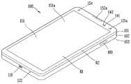
이하, 상술한 구성들이 구비된 이동 단말기(100)의 일 실시예를 도 2 및 3을 참조하여 살펴보기로 한다.Hereinafter, an embodiment of the
도 2 및 3을 참조하면, 개시된 이동 단말기(100)는, 바 형태의 단말기 바디를 구비하고 있다. 다만, 본 발명은 여기에 한정되지 않고 와치 타입, 클립 타입, 글래스 타입 또는 2 이상의 바디들이 상대 이동 가능하게 결합되는 폴더 타입, 플립 타입, 슬라이드 타입, 스윙 타입, 스위블 타입 등 다양한 구조에 적용될 수 있다. 이하의 설명은 이동 단말기의 특정 유형에 관련될 것이나, 이동 단말기의 특정유형에 관한 설명은 다른 타입의 이동 단말기에 일반적으로 적용될 수 있다.Referring to FIGS. 2 and 3, the disclosed
여기에서, 단말기 바디는 이동 단말기(100)를 적어도 하나의 집합체로 보아 이를 지칭하는 개념으로 이해될 수 있다.Here, the terminal body can be understood as a concept of referring to the
이동 단말기(100)는 외관을 이루는 케이스(예를 들면, 프레임, 하우징, 커버 등)를 포함한다. 도시된 바와 같이, 이동 단말기(100)는 프론트 케이스(101)와 리어 케이스(102)를 포함할 수 있다. 프론트 케이스(101)와 리어 케이스(102)의 결합에 의해 형성되는 내부 공간에는 각종 전자부품들이 배치된다. 프론트 케이스(101)와 리어 케이스(102) 사이에는 적어도 하나의 미들 케이스가 추가로 배치될 수 있다.The
단말기 바디의 전면에는 디스플레이부(151)가 배치되어 정보를 출력할 수 있다. 도시된 바와 같이, 디스플레이부(151)의 윈도우(151a)는 프론트 케이스(101)에 장착되어 프론트 케이스(101)와 함께 단말기 바디의 전면을 형성할 수 있다.A
경우에 따라서, 리어 케이스(102)에도 전자부품이 장착될 수 있다. 리어 케이스(102)에 장착 가능한 전자부품은 착탈 가능한 배터리, 식별 모듈, 메모리 카드 등이 있다. 이 경우, 리어 케이스(102)에는 장착된 전자부품을 덮기 위한 후면 커버(103)가 착탈 가능하게 결합될 수 있다. 따라서, 후면 커버(103)가 리어 케이스(102)로부터 분리되면, 리어 케이스(102)에 장착된 전자부품은 외부로 노출된다.In some cases, electronic components may also be mounted on the
도시된 바와 같이, 후면 커버(103)가 리어 케이스(102)에 결합되면, 리어 케이스(102)의 측면 일부가 노출될 수 있다. 경우에 따라서, 상기 결합시 리어 케이스(102)는 후면 커버(103)에 의해 완전히 가려질 수도 있다. 한편, 후면 커버(103)에는 카메라(121b)나 음향 출력부(152b)를 외부로 노출시키기 위한 개구부가 구비될 수 있다.As shown, when the
이러한 케이스들(101, 102, 103)은 합성수지를 사출하여 형성되거나 금속, 예를 들어 스테인레스 스틸(STS), 알루미늄(Al), 티타늄(Ti) 등으로 형성될 수도 있다.These
이동 단말기(100)는, 복수의 케이스가 각종 전자부품들을 수용하는 내부 공간을 마련하는 위의 예와 달리, 하나의 케이스가 상기 내부 공간을 마련하도록 구성될 수도 있다. 이 경우, 합성수지 또는 금속이 측면에서 후면으로 이어지는 유니 바디의 이동 단말기(100)가 구현될 수 있다.The
한편, 이동 단말기(100)는 단말기 바디 내부로 물이 스며들지 않도록 하는 방수부(미도시)를 구비할 수 있다. 예를 들어, 방수부는 윈도우(151a)와 프론트 케이스(101) 사이, 프론트 케이스(101)와 리어 케이스(102) 사이 또는 리어 케이스(102)와 후면 커버(103) 사이에 구비되어, 이들의 결합 시 내부 공간을 밀폐하는 방수부재를 포함할 수 있다.Meanwhile, the
이동 단말기(100)에는 디스플레이부(151), 제1 및 제2 음향 출력부(152a, 152b), 근접 센서(141), 조도 센서(142), 광 출력부(154), 제1 및 제2 카메라(121a, 121b), 제1 및 제2 조작유닛(123a, 123b), 마이크로폰(122), 인터페이스부(160) 등이 구비될 수 있다.The
이하에서는, 도 2 및 도 3에 도시된 바와 같이, 단말기 바디의 전면에 디스플레이부(151), 제1 음향 출력부(152a), 근접 센서(141), 조도 센서(142), 광 출력부(154) 및 제1 카메라(121a)가 배치되고, 단말기 바디의 측면에 제2 조작유닛(123b), 마이크로폰(122) 및 인터페이스부(160)가 배치되며, 단말기 바디의 후면에 제1 조작유닛(123a), 제2 음향 출력부(152b) 및 제2 카메라(121b)가 배치된 이동 단말기(100)를 일 예로 들어 설명한다.2 and 3, a
다만, 이들 구성은 이러한 배치에 한정되는 것은 아니다. 이들 구성은 필요에 따라 제외 또는 대체되거나, 다른 면에 배치될 수 있다. 예를 들어, 제1 조작유닛(123a)은 단말기 바디의 전면에 구비될 수 있으며, 제2 음향 출력부(152b)는 단말기 바디의 후면이 아닌 단말기 바디의 측면에 구비될 수 있다.However, these configurations are not limited to this arrangement. These configurations may be excluded or replaced as needed, or placed on different planes. For example, the
디스플레이부(151)는 이동 단말기(100)에서 처리되는 정보를 표시(출력)한다. 예를 들어, 디스플레이부(151)는 이동 단말기(100)에서 구동되는 응용 프로그램의 실행화면 정보, 또는 이러한 실행화면 정보에 따른 UI(User Interface), GUI(Graphic User Interface) 정보를 표시할 수 있다.The
디스플레이부(151)는 액정 디스플레이(liquid crystal display, LCD), 박막 트랜지스터 액정 디스플레이(thin film transistor-liquid crystal display, TFT LCD), 유기 발광 다이오드(organic light-emitting diode, OLED), 플렉서블 디스플레이(flexible display), 3차원 디스플레이(3D display), 전자잉크 디스플레이(e-ink display) 중에서 적어도 하나를 포함할 수 있다.The
또한, 디스플레이부(151)는 이동 단말기(100)의 구현 형태에 따라 2개 이상 존재할 수 있다. 이 경우, 이동 단말기(100)에는 복수의 디스플레이부들이 하나의 면에 이격되거나 일체로 배치될 수 있고, 또한 서로 다른 면에 각각 배치될 수도 있다.In addition, the
디스플레이부(151)는 터치 방식에 의하여 제어 명령을 입력 받을 수 있도록, 디스플레이부(151)에 대한 터치를 감지하는 터치 센서를 포함할 수 있다. 이를 이용하여, 디스플레이부(151)에 대하여 터치가 이루어지면, 터치 센서는 상기 터치를 감지하고, 제어부(180)는 이에 근거하여 상기 터치에 대응하는 제어명령을 발생시키도록 이루어질 수 있다. 터치 방식에 의하여 입력되는 내용은 문자 또는 숫자이거나, 각종 모드에서의 지시 또는 지정 가능한 메뉴 항목 등일 수 있다.The
한편, 터치 센서는, 터치 패턴을 구비하는 필름 형태로 구성되어 윈도우(151a)와 윈도우(151a)의 배면 상의 디스플레이(미도시) 사이에 배치되거나, 윈도우(151a)의 배면에 직접 패터닝되는 메탈 와이어가 될 수도 있다. 또는, 터치 센서는 디스플레이와 일체로 형성될 수 있다. 예를 들어, 터치 센서는, 디스플레이의 기판 상에 배치되거나, 디스플레이의 내부에 구비될 수 있다.The touch sensor may be a film having a touch pattern and disposed between the
이처럼, 디스플레이부(151)는 터치 센서와 함께 터치 스크린을 형성할 수 있으며, 이 경우에 터치 스크린은 사용자 입력부(123, 도 1a 참조)로 기능할 수 있다. 경우에 따라, 터치 스크린은 제1조작유닛(123a)의 적어도 일부 기능을 대체할 수 있다. 이하, 설명의 편의를 위하여 상기 이미지를 출력하는 디스플레이부(디스플레이 모듈)와 상기 터치 센서를 통합하여 터치 스크린으로 칭한다.In this way, the
제1 음향 출력부(152a)는 통화음을 사용자의 귀에 전달시키는 리시버(receiver)로 구현될 수 있으며, 제2 음향 출력부(152b)는 각종 알람음이나 멀티미디어의 재생음을 출력하는 라우드 스피커(loud speaker)의 형태로 구현될 수 있다.The first
디스플레이부(151)의 윈도우(151a)에는 제1 음향 출력부(152a)로부터 발생되는 사운드의 방출을 위한 음향홀이 형성될 수 있다. 다만, 본 발명은 이에 한정되는 것은 아니고, 상기 사운드는 구조물 간의 조립틈(예를 들어, 윈도우(151a)와 프론트 케이스(101) 간의 틈)을 따라 방출되도록 구성될 수 있다. 이 경우, 외관상 음향 출력을 위하여 독립적으로 형성되는 홀이 보이지 않거나 숨겨져 이동 단말기(100)의 외관이 보다 심플해질 수 있다.The
광 출력부(154)는 이벤트의 발생시 이를 알리기 위한 빛을 출력하도록 이루어진다. 상기 이벤트의 예로는 메시지 수신, 호 신호 수신, 부재중 전화, 알람, 일정 알림, 이메일 수신, 애플리케이션을 통한 정보 수신 등을 들 수 있다. 제어부(180)는 사용자의 이벤트 확인이 감지되면, 빛의 출력이 종료되도록 광 출력부(154)를 제어할 수 있다.The
제1 카메라(121a)는 촬영 모드 또는 화상통화 모드에서 이미지 센서에 의해 얻어지는 정지영상 또는 동영상의 화상 프레임을 처리한다. 처리된 화상 프레임은 디스플레이부(151)에 표시될 수 있으며, 메모리(170)에 저장될 수 있다.The
제1 및 제2 조작유닛(123a, 123b)은 이동 단말기(100)의 동작을 제어하기 위한 명령을 입력 받기 위해 조작되는 사용자 입력부(123)의 일 예로서, 조작부(manipulating portion)로도 통칭될 수 있다. 제1 및 제2 조작유닛(123a, 123b)은 터치, 푸시, 스크롤 등 사용자가 촉각적인 느낌을 받으면서 조작하게 되는 방식(tactile manner)이라면 어떤 방식이든 채용될 수 있다. 또한, 제1 및 제2 조작유닛(123a, 123b)은 근접 터치(proximity touch), 호버링(hovering) 터치 등을 통해서 사용자의 촉각적인 느낌이 없이 조작하게 되는 방식으로도 채용될 수 있다.The first and
본 도면에서는 제1 조작유닛(123a)이 푸시키(mechanical key)인 것으로 예시하나, 본 발명이 이에 한정되는 것은 아니다. 예를 들어, 제1 조작유닛(123a)은 터치키(touch key)가 되거나, 터치키와 푸시키의 조합으로 구성될 수 있다.In this figure, the
제1 및 제2 조작유닛(123a, 123b)에 의하여 입력되는 내용은 다양하게 설정될 수 있다. 예를 들어, 제1 조작유닛(123a)은 전원의 온/오프, 시작, 종료, 디스플레이부(151)의 터치 인식 모드로의 전환 등의 명령을 입력 받고, 제2 조작유닛(123b)은 제1 또는 제2 음향 출력부(152a, 152b)에서 출력되는 음향의 크기 조절, 디스플레이부(151)의 터치 인식 모드로의 전환 등의 명령을 입력 받을 수 있다.The contents input by the first and
제1 조작유닛(123a)은 단말기 바디의 두께방향으로 전면의 디스플레이부(151)와 중첩되게 배치될 수 있다. 일 예로, 사용자가 단말기 바디를 한 손으로 쥐었을 때 검지를 이용하여 용이하게 조작 가능하도록, 제1 조작유닛(123a)은 단말기 바디의 후면 상단부에 배치될 수 있다. 다만, 본 발명은 반드시 이에 한정되는 것은 아니며, 제1 조작유닛(123a)의 위치는 변경될 수 있다.The
이처럼 단말기 바디의 후면에 제1 조작유닛(123a)이 구비되는 경우, 이를 이용한 새로운 형태의 유저 인터페이스가 구현될 수 있다. 또한, 디스플레이부(151)가 보다 대화면(大畵面)으로 구성될 수 있다.When the
한편, 이동 단말기(100)에는 사용자의 지문을 인식하는 지문인식 센서가 구비될 수 있으며, 제어부(180)는 지문인식 센서를 통하여 감지되는 지문정보를 인증수단으로 이용할 수 있다. 상기 지문인식 센서는 디스플레이부(151) 또는 사용자 입력부(123)에 내장될 수 있다.Meanwhile, the
마이크로폰(122)은 사용자의 음성, 기타 소리 등을 입력 받도록 이루어진다. 마이크로폰(122)은 복수의 개소에 구비되어 스테레오 음향을 입력 받도록 구성될 수 있다.The
인터페이스부(160)는 이동 단말기(100)를 외부기기와 연결시킬 수 있는 통로가 된다. 예를 들어, 인터페이스부(160)는 다른 장치(예를 들어, 이어폰, 외장 스피커)와의 연결을 위한 접속전극, 근거리 통신을 위한 포트[예를 들어, 적외선 포트(IrDA Port), 블루투스 포트(Bluetooth Port), 무선 랜 포트(Wireless LAN Port) 등], 또는 이동 단말기(100)에 전원을 공급하기 위한 전원공급전극 중 적어도 하나일 수 있다. 이러한 인터페이스부(160)는 SIM(Subscriber Identification Module) 또는 UIM(User Identity Module), 정보 저장을 위한 메모리 카드 등의 외장형 카드를 수용하는 소켓의 형태로 구현될 수도 있다.The
단말기 바디의 후면에는 제2 카메라(121b)가 배치될 수 있다. 이 경우, 제2 카메라(121b)는 제1 카메라(121a)와 실질적으로 반대되는 촬영 방향을 가지게 된다.And a
제2 카메라(121b)는 적어도 하나의 라인을 따라 배열되는 복수의 렌즈를 포함할 수 있다. 복수의 렌즈는 행렬(matrix) 형식으로 배열될 수도 있다. 이러한 카메라는, ‘어레이(array) 카메라’로 명명될 수 있다. 제2카메라(121b)가 어레이 카메라로 구성되는 경우, 복수의 렌즈를 이용하여 다양한 방식으로 영상을 촬영할 수 있으며, 보다 나은 품질의 영상을 획득할 수 있다.The
플래시(124)는 제2 카메라(121b)에 인접하게 배치될 수 있다. 플래시(124)는 제2 카메라(121b)로 피사체를 촬영하는 경우에 피사체를 향하여 빛을 비추게 된다.The
단말기 바디에는 제2 음향 출력부(152b)가 추가로 배치될 수 있다. 제2 음향 출력부(152b)는 제1 음향 출력부(152a)와 함께 스테레오 기능을 구현할 수 있으며, 통화시 스피커폰 모드의 구현을 위하여 사용될 수도 있다.And a second
단말기 바디에는 무선 통신을 위한 적어도 하나의 안테나가 구비될 수 있다. 안테나는 단말기 바디에 내장되거나, 케이스에 형성될 수 있다. 예를 들어, 방송 수신 모듈(111, 도 1a 참조)의 일부를 이루는 안테나는 단말기 바디에서 인출 가능하게 구성될 수 있다. 또는, 안테나는 필름 타입으로 형성되어 후면 커버(103)의 내측면에 부착될 수도 있고, 도전성 재질을 포함하는 케이스가 안테나로서 기능하도록 구성될 수도 있다.The terminal body may be provided with at least one antenna for wireless communication. The antenna may be embedded in the terminal body or formed in the case. For example, an antenna constituting a part of the broadcast receiving module 111 (see FIG. 1A) may be configured to be able to be drawn out from the terminal body. Alternatively, the antenna may be formed in a film type and attached to the inner surface of the
단말기 바디에는 이동 단말기(100)에 전원을 공급하기 위한 전원 공급부(190, 도 1a 참조)가 구비된다. 전원 공급부(190)는 단말기 바디에 내장되거나, 단말기 바디의 외부에서 착탈 가능하게 구성되는 배터리(191)를 포함할 수 있다.The terminal body is provided with a power supply unit 190 (see FIG. 1A) for supplying power to the
배터리(191)는 인터페이스부(160)에 연결되는 전원 케이블을 통하여 전원을 공급받도록 구성될 수 있다. 또한, 배터리(191)는 무선충전기기를 통하여 무선충전 가능하도록 구성될 수도 있다. 상기 무선충전은 자기유도방식 또는 공진방식(자기공명방식)에 의하여 구현될 수 있다.The
한편, 본 도면에서는 후면 커버(103)가 배터리(191)를 덮도록 리어 케이스(102)에 결합되어 배터리(191)의 이탈을 제한하고, 배터리(191)를 외부 충격과 이물질로부터 보호하도록 구성된 것을 예시하고 있다. 배터리(191)가 단말기 바디에 착탈 가능하게 구성되는 경우, 후면 커버(103)는 리어 케이스(102)에 착탈 가능하게 결합될 수 있다.The
이동 단말기(100)에는 외관을 보호하거나, 이동 단말기(100)의 기능을 보조 또는 확장시키는 액세서리가 추가될 수 있다. 이러한 액세서리의 일 예로, 이동 단말기(100)의 적어도 일면을 덮거나 수용하는 커버 또는 파우치를 들 수 있다. 커버 또는 파우치는 디스플레이부(151)와 연동되어 이동 단말기(100)의 기능을 확장시키도록 구성될 수 있다. 액세서리의 다른 일 예로, 터치 스크린에 대한 터치입력을 보조 또는 확장하기 위한 터치펜을 들 수 있다.The
한편, 본 발명의 이동 단말기(100)에는 압전 액추에이터(153a)가 구비되어, 이동 단말기(100)에 진동을 가하거나, 이동 단말기(100)에 가해지는 힘을 감지하도록 이루어진다. 압전 액추에이터(153a)는 햅틱 모듈(153)의 일 예로 이해될 수 있다.Meanwhile, the
이하에서는, 압전 액추에이터(153a)가 지문인식 센서(143)와 함께 배치된 구조에 대하여 설명하기로 한다.Hereinafter, a structure in which the
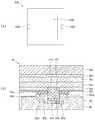
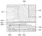
도 4의 (a)는 본 발명의 이동 단말기(100)에 적용되는 압전 액추에이터(153a)의 일 예를 보인 평면도이고, (b)는 (a)에 도시된 압전 액추에이터(153a)가 지문인식 센서(143)와 함께 배치된 구조를 보인 개념도이다.4A is a plan view showing an example of a
도 4의 (a)를 참조하면, 압전 액추에이터(153a)는 중공부(153a')를 구비하는 환형으로 형성된다. 도시된 바와 같이, 압전 액추에이터(153a)는 사각기둥 형태로 형성될 수 있으며, 중공부(153a')도 사각 형태를 가질 수 있다.Referring to FIG. 4A, the
전기적 연결을 위한 제1 및 제2전극(153a1, 153a2)은 압전 액추에이터(153a)의 상면에 구비될 수 있다. 제1 및 제2전극(153a1, 153a2)은 각각 +전극과 -전극으로 이해될 수 있다. 본 도면에서는, 압전 액추에이터(153a)의 서로 직교하는 네 상면들 중 중공부(153a')를 사이에 두고 서로 나란하게 배치되는 두 상면들에 각각 제1전극(153a1)과 제2전극(153a2)이 배치된 것을 보이고 있다.The first and second electrodes 153a1 and 153a2 for electrical connection may be provided on the upper surface of the
도시된 바와 같이, 제1 및 제2전극(153a1, 153a2)은 압전 액추에이터(153a)의 중심을 기준으로 상호 위치에 형성될 수 있다. 또는, 제1 및 제2전극(153a1, 153a2)의 상호 구별이 용이하도록, 제1 및 제2전극(153a1, 153a2)은 압전 액추에이터(153a)의 중심을 기준으로 상호 비대칭적인 위치에 형성될 수 있다.As shown in the figure, the first and second electrodes 153a1 and 153a2 may be formed at mutually positions with respect to the center of the
도 4의 (b)를 참조하면, 압전 액추에이터(153a)는 디스플레이부(151)의 배면 상에 위치한다. 즉, 압전 액추에이터(153a)는 이동 단말기(100)의 두께 방향으로 디스플레이부(151)와 오버랩되게 배치된다. 상기 배치에 의해, 압전 액추에이터(153a)는 디스플레이부(151)에 진동을 전달하거나, 디스플레이부(151)에 가해지는 힘을 감지하도록 이루어진다.4 (b), the
압전 액추에이터(153a)의 중공부(153a')에는 지문인식 센서(143)가 수용된다. 따라서, 지문인식 센서(143)도 디스플레이부(151)의 배면 상에 위치한다. 즉, 지문인식 센서(143)는 이동 단말기(100)의 두께 방향으로 디스플레이부(151)와 오버랩되게 배치되어, 지문인식 센서(143) 상의 디스플레이부(151)에 접촉된 손가락의 지문을 감지하도록 이루어진다.A
지문인식 센서(143)는 초음파 방식 또는 옵티컬 방식으로 작동할 수 있다. 지문인식 센서(143)가 디스플레이부(151)의 배면 상에 배치되는 구조상, 본 구조는 OLED 디스플레이(151d)에 적용되는 것이 바람직하다. 지문인식 센서(143)가 LCD 디스플레이(151d)의 배면 상에 배치되는 경우, LCD 내부 구조물에 의해 빛의 반사 내지는 굴절, 초음파의 굴절 내지는 차단이 일어날 수 있다.The
본 도면에서는, 디스플레이부(151)가 윈도우(151a)와 OLED 디스플레이(151d)를 포함하여 구성된 것을 보이고 있다.In this figure, the
윈도우(151a)는 투광성으로 형성되며, 이동 단말기(100)의 일면(본 도면에서는, 정면)을 이룬다. 윈도우(151a)는 글래스 재질, 합성수지 재질 등으로 구성될 수 있다.The
디스플레이부(151)는 OLED 디스플레이(151d)에 대응되는 투광 영역(R1, 도 2 참조)과 상기 투광 영역(R1)을 감싸는 불투광 영역(R2, 도 2 참조)을 포함할 수 있다. 이러한 투광 영역(R1)과 불투광 영역(R2)의 형성을 위해, 윈도우(151a)의 일면에는 데코 레이어(151b)가 배치될 수 있다.The
데코 레이어(151b)는 불투광 재질로 형성되고, 윈도우(151a)의 배면에 인쇄되어 불투광 영역(R2)을 형성한다. 또는, 데코 레이어(151b)는 필름 형태로 형성되어 윈도우(151a)의 일면에 부착될 수 있다. 예를 들어, 필름형 데코 레이어(151b)는 투광 영역(R1)을 형성하는 투광 부분과 불투광 영역(R2)을 형성하는 불투광 부분을 포함할 수 있다.The
이하에서는, 설명의 편의상, 데코 레이어(151b)가 형성 내지 부착된 윈도우(151a)를 윈도우부로 명명하기로 한다.Hereinafter, for convenience of description, the
OLED 디스플레이(151d)는 윈도우부의 배면에 배치되어, 윈도우부를 통하여 시각 정보를 출력하도록 구성된다. 여기서, OLED 디스플레이(151d)에는 통상의 Glass OLED 디스플레이뿐만 아니라, Plastic OLED 디스플레이(151d)가 포함될 수 있다.The
OLED 디스플레이(151d)는 윈도우부의 배면에 부착될 수 있다. 상기 부착을 위하여, OLED 디스플레이(151d)와 윈도우부 사이에는 투광성 접착층(151c), 예를 들어, OCA(Optically Clear Adhesive) 또는 OCR(Optically Clear Resin)이 배치될 수 있다.The
OLED 디스플레이(151d)의 배면에는 완충시트(151e)가 부착될 수 있다. 상기 완충시트(151e)에 의해 OLED 디스플레이(151d)가 외부 충격으로부터 보호될 수 있다. 일 예로, 완충시트(151e)는 폴리우레탄(Polyurethane) 재질로 형성될 수 있으며, 폼(foam) 형태를 가질 수 있다.A
완충시트(151e)의 배면에는 OLED 디스플레이(151d)에서 발생한 열을 분산시키는 써멀시트(151f, thermal sheet)가 부착될 수 있다. 써멀시트(151f)는 그라파이트, 구리, 알루미늄 등 열전도성이 높은 재질을 포함하여 형성될 수 있다.A
디스플레이부(151)의 배면 상에는 지문인식 센서(143)와 압전 액추에이터(153a)가 배치된다. 지문인식 센서(143)와 압전 액추에이터(153a)는 이동 단말기(100)의 두께 방향으로 상술한 투광 영역(R1)에 오버랩되도록 배치될 수 있다.A
지문인식 센서(143)는 초음파 방식 또는 옵티컬 방식으로 윈도우(151a)에 접촉된 손가락의 지문을 감지하도록 이루어지므로, 윈도우(151a)와 지문인식 센서(143) 사이에 빛의 반사 내지는 굴절, 초음파의 굴절 내지는 차단이 유발되는 구성이 개재되지 않아야 한다.Since the
따라서, 지문인식 센서(143)는 OLED 디스플레이(151d)의 배면에 부착되는 것이 바람직하다. 상기 부착을 위하여, OLED 디스플레이(151d)와 지문인식 센서(143) 사이에는 투광성 접착층(144a), 예를 들어, OCA(Optically Clear Adhesive) 또는 OCR(Optically Clear Resin)이 배치될 수 있다.Therefore, the
상기 배치에 따라, 상술한 완충시트(151e)와 써멀시트(151f)에는 지문인식 센서(143)에 대응되는 부분이 절개된 형태를 가질 수 있다. 즉, 지문인식 센서(143)는 상기 절개된 형태를 갖는 부분(이하, 절개부)에 수용되어 완충시트(151e)와 써멀시트(151f)에 의해 둘러싸일 수 있다. 상기 절개부는 지문인식 센서(143)의 둘레 형상에 대응되게 형성되는 것이 바람직하다. 예를 들어, 지문인식 센서(143)가 사각기둥 형태를 가지는 경우, 상기 절개부는 사각 형태로 형성될 수 있다.According to the arrangement, the
지문인식 센서(143)는 연성인쇄회로기판(144b)을 통하여 제어부(180)와 전기적으로 연결될 수 있다. 본 도면에서는, 연성인쇄회로기판(144b)이 지문인식 센서(143)의 배면에 배치된 일 예를 보이고 있다.The
지문인식 센서(143)는 프레임(104) 내지는 주변 기구물[예를 들어, 배터리(191)]에 의해 지지될 수 있다. 본 도면에서는, 지문인식 센서(143)가 배터리(191)에 의해 지지되는 구조를 보이고 있다. 지문인식 센서(143)와 배터리(191) 사이에는 보강재(144c)가 배치될 수 있다. 보강재(144c)는 연성인쇄회로기판(144b)의 배면에 부착될 수 있다.The
압전 액추에이터(153a)는 지문인식 센서(143)를 감싸는 환형으로 형성된다. 지문인식 센서(143)의 수용을 위한 중공부(153a')는 지문인식 센서(143)의 둘레 형상에 대응되게 형성되는 것이 바람직하다. 예를 들어, 지문인식 센서(143)가 사각기둥 형태를 가지는 경우, 중공부(153a')는 사각 형태를 가질 수 있다.The
압전 액추에이터(153a)는 써멀시트(151f)의 배면에 부착되어, 디스플레이부(151)에 진동을 전달하거나, 디스플레이부(151)에 가해지는 힘을 감지하도록 이루어진다.The
압전 액추에이터(153a)의 상면에는 제1 및 제2전극(153a1, 153a2)이 각각 배치된다. 제1 및 제2전극(153a1, 153a2)은 중공부(153a')의 양측 상면에 각각 배치될 수 있다. 제1 및 제2전극(153a1, 153a2)은 연성회로(155b)를 통하여 제어부(180)와 전기적으로 연결된다.First and second electrodes 153a1 and 153a2 are disposed on the upper surface of the
연성회로(155b)는 써멀시트(151f)와 압전 액추에이터(153a) 사이에 배치되어, 제1 및 제2전극(153a1, 153a2)과 전기적으로 연결된다. 연성회로(155b)는 회로의 손상 없이 일정 수준 내에서 휘어짐이 가능하게 구성된다. 연성회로(155b)는 전도성 박막(Conductive Foil), 연성회로기판(FPC: Flexible Printed Circuit), 또는 연성평판케이블(FFC: Flexible Flat Cable)이 될 수 있다.The
연성회로(155b)와 제1 및 제2전극(153a1, 153a2)의 전기적 연결을 위하여, 연성회로(155b)와 제1 및 제2전극(153a1, 153a2) 사이에는 전도성 접착제(155c1, 155c2)가 배치될 수 있다. 전도성 접착제(155c1, 155c2)는 은(Ag), 구리(Cu), 카본 등 다양한 재질로 형성될 수 있다.Conductive adhesives 155c1 and 155c2 are provided between the
제1 및 제2전극(153a1, 153a2)이 중공부(153a')의 양측에 배치되는 구조상, 연성회로(155b)는 환형으로 형성되어 중공 부분에 지문인식 센서(143)를 수용하도록 구성될 수 있다. 연성회로(155b)의 중공 부분은 압전 액추에이터(153a)의 중공부(153a')에 대응되는 형상을 가질 수 있다.The first and second electrodes 153a1 and 153a2 are disposed on both sides of the
연성회로(155b)는 써멀시트(151f)의 배면에 부착된다. 상기 부착을 위해, 써멀시트(151f)와 연성회로(155b) 사이에는 접착층(155a)이 배치될 수 있다. 상기 접착층(155a)은 OCA(Optically Clear Adhesive) 또는 OCR(Optically Clear Resin)뿐만 아니라, 투광성을 갖지 않는 여타 공지된 접착 필름 내지 접착제로 구성될 수 있다. 상기 부착에 의해, 압전 액추에이터(153a)에서 발생되는 진동이 윈도우(151a)로 전달될 수 있고, 윈도우(151a)에 가해지는 압력이 압전 액추에이터(153a)로 전달될 수 있다.The
압전 액추에이터(153a)는 프레임(104) 내지는 주변 기구물[예를 들어, 배터리(191)]에 의해 지지될 수 있다. 본 도면에서는, 지문인식 센서(143)가 이동 단말기(100) 내부의 프레임(104)에 의해 지지되는 구조를 보이고 있다. 상기 프레임(104)은 금속 재질(예를 들어, SUS, 알루미늄 등) 또는 합성수지 재질로 형성될 수 있다.The
도시된 바와 같이, 프레임(104)은 지문인식 센서(143)에 대응되는 중공을 구비할 수 있다. 상기 중공에는 상술한 보강재(144c)가 배치될 수 있으며, 보강재(144c)를 감싸는 댐퍼(155d)가 구비될 수 있다. 댐퍼(155d)는 폴리우레탄(Polyurethane) 재질로 형성될 수 있으며, 폼(foam) 형태를 가질 수 있다.As shown, the
댐퍼(155d)는 압전 액추에이터(153a)의 적어도 일부를 지지하도록 구성될 수 있다. 즉, 압전 액추에이터(153a)의 일부는 프레임(104)에 의해 지지되고, 다른 일부는 댐퍼(155d)에 의해 지지될 수 있다.The
상술한 바와 같이, 압전 액추에이터(153a)의 중공부(153a')를 기준으로 양측 상면에 제1 및 제2전극(153a1, 153a2)이 구비되는 구조에서는, 연성회로(155b)가 상기 양측 상면을 모두 덮도록 배치되므로, 연성회로(155b)에 의한 단차가 발생하지 않는다. 따라서, 별도의 기구물이 없이도 압전 액추에이터(153a)에서 발생되는 진동이 윈도우(151a)로 전달될 수 있고, 윈도우(151a)에 가해지는 압력이 압전 액추에이터(153a)로 전달될 수 있다.As described above, in the structure in which the first and second electrodes 153a1 and 153a2 are provided on both upper surfaces with respect to the
도 5의 (a)는 본 발명의 이동 단말기에 적용되는 압전 액추에이터(253a)의 다른 일 예를 보인 평면도이고, (b)는 (a)에 도시된 압전 액추에이터(253a)가 지문인식 센서(243)와 함께 배치된 구조를 보인 개념도이다.5A is a plan view showing another example of the
본 예에서는 압전 액추에이터(253a)의 제1 및 제2전극(253a1, 253a2)이 중공부(253a')의 일측 상면에 구비된다. 이로 인하여, 압전 액추에이터(253a)와 연성회로(255b)의 전기적 연결 구조 및 상기 전기적 연결 구조로 인하여 발생하는 단차를 해결하기 위한 구조가 앞서 도 4에서 설명한 구조와 상이하다.In this example, the first and second electrodes 253a1 and 253a2 of the
도 5의 (a)를 참조하면, 압전 액추에이터(253a)는 중공부(253a')를 구비하는 환형으로 형성된다. 도시된 바와 같이, 압전 액추에이터(253a)는 사각기둥 형태로 형성될 수 있으며, 중공부(253a')도 사각 형태를 가질 수 있다.Referring to FIG. 5A, the
제1 및 제2전극(253a1, 253a2)은 압전 액추에이터(253a)의 일측 상면에 구비될 수 있다. 본 도면에서는, 압전 액추에이터(253a)의 서로 직교하는 네 상면들 중 하나의 상면에 제1전극(253a1)과 제2전극(253a2)이 배치된 것을 보이고 있다.The first and second electrodes 253a1 and 253a2 may be provided on one upper surface of the
도 5의 (b)를 참조하면, 압전 액추에이터(253a)는 디스플레이부(251)의 배면 상에 위치한다. 즉, 압전 액추에이터(253a)는 이동 단말기의 두께 방향으로 디스플레이부(251)와 오버랩되게 배치된다. 상기 배치에 의해, 압전 액추에이터(253a)는 디스플레이부(251)에 진동을 전달하거나, 디스플레이부(251)에 가해지는 힘을 감지하도록 이루어진다.Referring to Fig. 5B, the
압전 액추에이터(253a)의 중공부(253a')에는 지문인식 센서(243)가 수용된다. 따라서, 지문인식 센서(243)도 디스플레이부(251)의 배면 상에 위치한다. 즉, 지문인식 센서(243)는 이동 단말기의 두께 방향으로 디스플레이부(251)와 오버랩되게 배치되어, 지문인식 센서(243) 상의 디스플레이부(251)에 접촉된 손가락의 지문을 감지하도록 이루어진다.A
지문인식 센서(243)는 초음파 방식 또는 옵티컬 방식으로 작동할 수 있다. 지문인식 센서(243)가 디스플레이부(251)의 배면 상에 배치되는 구조상, 본 구조는 OLED 디스플레이(251d)에 적용되는 것이 바람직하다. 지문인식 센서(243)가 LCD 디스플레이(251d)의 배면 상에 배치되는 경우, LCD 내부 구조물에 의해 빛의 반사 내지는 굴절, 초음파의 굴절 내지는 차단이 일어날 수 있다.The
본 도면에서는, 디스플레이부(251)가 윈도우(251a)와 OLED 디스플레이(251d)를 포함하여 구성된 것을 보이고 있다.In this figure, the
윈도우(251a)는 투광성으로 형성되며, 이동 단말기의 일면(본 도면에서는, 정면)을 이룬다. 윈도우(251a)는 글래스 재질, 합성수지 재질 등으로 구성될 수 있다.The
디스플레이부(251)는 OLED 디스플레이(251d)에 대응되는 투광 영역(R1, 도 2 참조)과 상기 투광 영역(R1)을 감싸는 불투광 영역(R2, 도 2 참조)을 포함할 수 있다. 이러한 투광 영역(R1)과 불투광 영역(R2)의 형성을 위해, 윈도우(251a)의 일면에는 데코 레이어(251b)가 배치될 수 있다.The
데코 레이어(251b)는 불투광 재질로 형성되고, 윈도우(251a)의 배면에 인쇄되어 불투광 영역(R2)을 형성한다. 또는, 데코 레이어(251b)는 필름 형태로 형성되어 윈도우(251a)의 일면에 부착될 수 있다. 예를 들어, 필름형 데코 레이어(151b)는 투광 영역(R1)을 형성하는 투광 부분과 불투광 영역(R2)을 형성하는 불투광 부분을 포함할 수 있다.The
이하에서는, 설명의 편의상, 데코 레이어(251b)가 형성 내지 부착된 윈도우(251a)를 윈도우부로 명명하기로 한다.Hereinafter, for convenience of description, the
OLED 디스플레이(251d)는 윈도우부의 배면에 배치되어, 윈도우부를 통하여 시각 정보를 출력하도록 구성된다. 여기서, OLED 디스플레이(251d)에는 통상의 Glass OLED 디스플레이뿐만 아니라, Plastic OLED 디스플레이(251d)가 포함될 수 있다.The
OLED 디스플레이(251d)는 윈도우부의 배면에 부착될 수 있다. 상기 부착을 위하여, OLED 디스플레이(251d)와 윈도우부 사이에는 투광성 접착층, 예를 들어, OCA(Optically Clear Adhesive) 또는 OCR(Optically Clear Resin)이 배치될 수 있다.The
OLED 디스플레이(251d)의 배면에는 완충시트(251e)가 부착될 수 있다. 상기 완충시트(251e)에 의해 OLED 디스플레이(251d)가 외부 충격으로부터 보호될 수 있다. 일 예로, 완충시트(251e)는 폴리우레탄(Polyurethane) 재질로 형성될 수 있으며, 폼(foam) 형태를 가질 수 있다.A
완충시트(251e)의 배면에는 OLED 디스플레이(251d)에서 발생한 열을 분산시키는 써멀시트(251f, thermal sheet)가 부착될 수 있다. 써멀시트(251f)는 그라파이트, 구리, 알루미늄 등 열전도성이 높은 재질을 포함하여 형성될 수 있다.A
디스플레이부(251)의 배면 상에는 지문인식 센서(243)와 압전 액추에이터(253a)가 배치된다. 지문인식 센서(243)와 압전 액추에이터(253a)는 이동 단말기의 두께 방향으로 상술한 투광 영역(R1)에 오버랩되도록 배치될 수 있다.A
지문인식 센서(243)는 초음파 방식 또는 옵티컬 방식으로 윈도우(251a)에 접촉된 손가락의 지문을 감지하도록 이루어지므로, 윈도우(251a)와 지문인식 센서(243) 사이에 빛의 반사 내지는 굴절, 초음파의 굴절 내지는 차단이 유발되는 구성이 개재되지 않아야 한다.The
따라서, 지문인식 센서(243)는 OLED 디스플레이(251d)의 배면에 부착되는 것이 바람직하다. 상기 부착을 위하여, OLED 디스플레이(251d)와 지문인식 센서(243) 사이에는 투광성 접착층, 예를 들어, OCA(Optically Clear Adhesive) 또는 OCR(Optically Clear Resin)이 배치될 수 있다.Therefore, the
상기 배치에 따라, 상술한 완충시트(251e)와 써멀시트(251f)에는 지문인식 센서(243)에 대응되는 부분이 절개된 형태를 가질 수 있다. 즉, 지문인식 센서(243)는 상기 절개된 형태를 갖는 부분(이하, 절개부)에 수용되어 완충시트(251e)와 써멀시트(251f)에 의해 둘러싸일 수 있다. 상기 절개부는 지문인식 센서(243)의 둘레 형상에 대응되게 형성되는 것이 바람직하다. 예를 들어, 지문인식 센서(243)가 사각기둥 형태를 가지는 경우, 절개부는 사각 형태로 형성될 수 있다.According to the above arrangement, the
지문인식 센서(243)는 연성인쇄회로기판(244b)을 통하여 제어부(180)와 전기적으로 연결될 수 있다. 본 도면에서는, 연성인쇄회로기판(244b)이 지문인식 센서(243)의 배면에 배치된 일 예를 보이고 있다.The
지문인식 센서(243)는 프레임(204) 내지는 주변 기구물[예를 들어, 배터리(291)]에 의해 지지될 수 있다. 본 도면에서는, 지문인식 센서(243)가 배터리(291)에 의해 지지되는 구조를 보이고 있다. 지문인식 센서(243)와 배터리(291) 사이에는 보강재(244c)가 배치될 수 있다. 보강재(244c)는 연성인쇄회로기판(244b)의 배면에 부착될 수 있다.The
압전 액추에이터(253a)는 지문인식 센서(243)를 감싸는 환형으로 형성된다. 지문인식 센서(243)의 수용을 위한 중공부(253a')는 지문인식 센서(243)의 둘레 형상에 대응되게 형성되는 것이 바람직하다. 예를 들어, 지문인식 센서(243)가 사각기둥 형태를 가지는 경우, 중공부(253a')는 사각 형태을 가질 수 있다.The
압전 액추에이터(253a)의 상면에는 제1 및 제2전극(253a1, 253a2)이 각각 배치된다. 제1 및 제2전극(253a1, 253a2)은 중공부(253a')의 일측 상면에 배치될 수 있다. 제1 및 제2전극(253a1, 253a2)은 연성회로(255b)를 통하여 제어부(180)와 전기적으로 연결된다.First and second electrodes 253a1 and 253a2 are disposed on the upper surface of the
연성회로(255b)는 써멀시트(251f)와 압전 액추에이터(253a) 사이에 배치되어, 제1 및 제2전극(253a1, 253a2)과 전기적으로 연결된다. 연성회로(255b)는 회로의 손상 없이 일정 수준 내에서 휘어짐이 가능하게 구성된다. 연성회로(255b)는 전도성 박막(Conductive Foil), 연성회로기판(FPC: Flexible Printed Circuit), 또는 연성평판케이블(FFC: Flexible Flat Cable)이 될 수 있다.The
연성회로(255b)와 제1 및 제2전극(253a1, 253a2)의 전기적 연결을 위하여, 연성회로(255b)와 제1 및 제2전극(253a1, 253a2) 사이에는 전도성 접착제(255c1, 255c2)가 배치될 수 있다. 전도성 접착제(255c1, 255c2)는 은(Ag), 구리(Cu), 카본 등 다양한 재질로 형성될 수 있다.Conductive adhesives 255c1 and 255c2 are provided between the
제1 및 제2전극(253a1, 253a2)이 중공부(253a')의 일측 상면에 배치되는 구조상, 연성회로(255b)는 제1 및 제2전극(253a1, 253a2)과의 전기적 연결을 위해 상기 일측 상면만을 덮도록 배치될 수 있다. 즉, 상기 일측 상면을 제외한 다른 상면 상에는 연성회로(255b)가 미배치될 수 있다. 예를 들어, 도시된 바와 같이, 압전 액추에이터(253a) 상면의 서로 직교하는 네 상면들 중 하나의 상면에 제1 및 제2전극(253a1, 253a2)이 형성되는 경우, 연성회로(255b)는 상기 하나의 상면만을 덮도록 배치되고, 다른 세 상면들을 덮지 않도록 구성될 수 있다.The first and second electrodes 253a1 and 253a2 are disposed on one upper surface of the
상기 배치에 의하면, 써멀시트(251f)의 배면으로부터 연성회로(255b)까지의 거리와, 써멀시트(251f)의 배면으로부터 연성회로(255b)가 미배치된 다른 세 상면들 사이의 거리에 차이가 발생하게 된다. 이러한 거리 차이, 즉 단차로 인하여, 앞선 실시예와 같이 연성회로(255b)를 써멀시트(251f)의 배면에 부착하기가 어려운 문제가 있다.According to this arrangement, the distance from the back surface of the
이에 본 실시예에서는, 써멀시트(251f)와 압전 액추에이터(253a) 사이에 진동전달부재(255d)가 개재되는 구조를 개시한다. 상기 진동전달부재(255d)는 압전 액추에이터(253a)를 써멀시트(251f)의 배면 상에 고정시키기 위한 구성이라는 점에서 브래킷으로 명명될 수도 있다.Thus, in this embodiment, a structure in which the
구체적으로, 진동전달부재(255d)는 중공 부분을 구비하는 환형으로 형성되어 상기 중공 부분에 지문인식 센서(243)를 수용하도록 구성되며, 연성회로(255b) 및 연성회로(255b)가 미배치되는 압전 액추에이터(253a)의 세 상면들을 덮도록 배치된다.More specifically, the
진동전달부재(255d)는 제1부분(255d1)과 제2부분(255d2)을 포함한다. 제1부분(255d1)은 연성회로(255b)와 써멀시트(251f) 사이에 배치된다. 제2부분(255d2)은 제1부분(255d1)에서 연장되어 압전 액추에이터(253a)와 써멀시트(251f) 사이에 배치되고, 제1부분(255d1)보다 증가된 두께를 갖는다. 제1 및 제2부분(255d1, 255d2)은 중공부(253a')를 구비하는 환형으로 형성되어 상기 중공부(253a')에 지문인식 센서(243)를 수용하도록 구성된다.The
진동전달부재(255d)는 제2부분(255d2)에서 하방으로 연장되는 지지부분(255d3)을 더 포함할 수 있다. 지지부분(255d3)은 압전 액추에이터(253a)가 지지되는 프레임(204) 내지는 주변 기구물에 지지된다. 도 5의 (b)에 도시된 바와 같이, 연성회로(255b)와 지지부분(255d3)은 지문인식 센서(243)를 사이에 두고 양측에 각각 배치된다.The
압전 액추에이터(253a)는 프레임(204) 내지는 주변 기구물[예를 들어, 배터리(291)]에 의해 지지될 수 있다. 본 도면에서는, 지문인식 센서(243)가 이동 단말기 내부의 프레임(204)에 의해 지지되는 구조를 보이고 있다. 상기 프레임(204)은 금속 재질(예를 들어, SUS, 알루미늄 등)로 형성될 수 있다.The
도시된 바와 같이, 프레임(204)은 지문인식 센서(243)에 대응되는 중공을 구비할 수 있다. 중공에는 상술한 보강재(244c)가 배치될 수 있으며, 보강재(244c)를 감싸는 댐퍼(255d)가 구비될 수 있다. 댐퍼(255d)는 폴리우레탄(Polyurethane) 재질로 형성될 수 있으며, 폼(foam) 형태를 가질 수 있다.As shown, the
댐퍼(255d)는 압전 액추에이터(253a)의 적어도 일부를 지지하도록 구성될 수 있다. 즉, 압전 액추에이터(253a)의 일부는 프레임(204)에 의해 지지되고, 다른 일부는 댐퍼(255d)에 의해 지지될 수 있다.The
상술한 두 실시예에서는 지문인식 센서(143, 243)에 연결되는 연성인쇄회로기판(144b, 244b)과 압전 액추에이터(153a, 253a)에 연결되는 연성회로(155b, 255b)가 서로 별도로 구비되는 구조를 보였다. 이하에서는, 하나의 연성인쇄회로기판(344b)을 통하여 지문인식 센서(343)와 압전 액추에이터(353a)가 제어부(180)와 전기적으로 연결되는 구조에 대하여 설명한다.The flexible printed
도 6은 본 발명의 이동 단말기(300)에 적용되는 압전 액추에이터(353a)가 지문인식 센서(343)의 연성인쇄회로기판(344b)에 전기적으로 연결되는 구조를 설명하기 위한 개념도이다.6 is a conceptual diagram illustrating a structure in which a
도 6을 참조하면, 지문인식 센서(343)는 연성인쇄회로기판(344b)을 통하여 제어부(180)와 전기적으로 연결된다. 연성인쇄회로기판(344b)은 지문인식 센서(343)의 일측면으로부터 연장된다.6, the
압전 액추에이터(353a)는 지문인식 센서(343)를 감싸는 환형으로 형성된다. 지문인식 센서(343)의 수용을 위한 중공부(353a')는 지문인식 센서(343)의 둘레 형상에 대응되게 형성되는 것이 바람직하다. 예를 들어, 지문인식 센서(343)가 사각기둥 형태를 가지는 경우, 중공부(353a')는 사각 형태를 가질 수 있다.The
압전 액추에이터(353a)의 상면에는 제1 및 제2전극(353a1, 353a2)이 각각 배치된다. 제1 및 제2전극(353a1, 353a2)은 중공부(353a')의 일측 상면에 배치될 수 있다. 제1 및 제2전극(353a1, 353a2)은 연성회로(355b)를 통하여 제어부(180)와 전기적으로 연결된다.First and second electrodes 353a1 and 353a2 are disposed on the upper surface of the
지문인식 센서(343)가 압전 액추에이터(353a)의 중공부(353a')에 수용된 상태에서, 연성인쇄회로기판(344b)은 압전 액추에이터(353a)의 일측 상면을 지나 압전 액추에이터(353a)의 측방향으로 연장된다. 이때, 상기 일측 상면에는 제1 및 제2전극(353a1, 353a2)이 구비되며, 상기 일측 상면과 마주하는 연성인쇄회로기판(344b)의 배면에는 상기 제1 및 제2전극(353a1, 353a2)과의 전기적 연결을 위한 제1 및 제2단자(344b1, 344b2)가 구비된다.The flexible printed
즉, 지문인식 센서(343)가 압전 액추에이터(353a)의 중공부(353a')에 수용된 상태에서, 제1단자(344b1)는 제1전극(353a1)과 마주하도록 배치되고, 제2단자(344b2)는 제2전극(353a2)과 마주하도록 배치된다. 제1 및 제2전극(353a1, 353a2)과 제1 및 제2단자(344b1, 344b2)의 전기적 연결을 위하여, 이들 사이에는 전도성 접착제(미도시)가 배치될 수 있다. 전도성 접착제는 은(Ag), 구리(Cu), 카본 등 다양한 재질로 형성될 수 있다.That is, in a state in which the
상기 구조에 의하면, 하나의 연성인쇄회로기판(344b)을 통하여 지문인식 센서(343)와 압전 액추에이터(353a)가 제어부(180)와 전기적으로 연결될 수 있다. 따라서, 압전 액추에이터(353a)의 전기적 연결을 위한 연성회로(355b)가 불필요하여, 전기적 연결을 위한 구조가 보다 심플하게 구성될 수 있다.According to the above structure, the
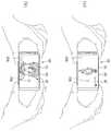
도 7은 본 발명의 이동 단말기에 적용되는 조작유닛에 압전 액추에이터(453a)가 적용된 구조를 보인 개념도이다.7 is a conceptual diagram showing a structure in which a
앞선 도 3과 관련하여 설명한 바와 같이, 이동 단말기(100)의 전면에는 시각 정보를 출력하는 디스플레이부(151)가 구비되고, 후면에는 제1조작유닛(123a)이 구비된다. 도 7은 이러한 제1조작유닛(123a)에 압전 액추에이터(453a)가 적용된 구조를 보이고 있다.3, a
도 7을 참조하면, 제1조작유닛(123a)은 구비되는 위치를 고려하여 후방키(423a)로 명명될 수 있다. 후방키(423a)는 누름 조작이 가능한 통상의 기계식 버튼은 아니지만, 기계식 버튼을 조작했을 때와 유사한 햅틱 효과를 사용자에게 제공한다는 점에서, 일종의 키로 불릴 수 있다.Referring to FIG. 7, the
후방키(423a)는 사용자의 지문을 감지하도록 이루어지고, 사용자에게 진동을 전달하거나 사용자에 의해 가해지는 힘을 감지하도록 구성된다. 후방키(423a)는 이동 단말기의 후면으로 노출되며, 이동 단말기의 두께 방향으로 디스플레이부와 중첩되게 배치된다.The back key 423a is configured to sense the fingerprint of the user and is configured to transmit vibration to the user or to sense the force applied by the user. The rear key 423a is exposed to the rear surface of the mobile terminal and is arranged to overlap the display part in the thickness direction of the mobile terminal.
후방키(423a)에는 지문인식 센서(443)가 내장될 수 있다. 지문인식 센서(443)는 초음파 방식 또는 옵티컬 방식으로 작동할 수 있다. 지문인식 센서(443)는 연성인쇄회로기판(444b)를 통하여 제어부와 전기적으로 연결될 수 있다.A
후방키(423a)는 지문인식 센서(443)가 후방키(423a)에 접촉된 손가락의 지문을 인식할 때, 빛의 반사 내지는 굴절, 초음파의 굴절 내지는 차단을 줄일 수 있도록, 투광성 재질로 형성되는 것이 바람직하다. 후방키(423a)는 글래스, 합성수지 등의 재질로 형성될 수 있다.The back key 423a is formed of a transparent material so as to reduce reflection or refraction of light or refraction or blocking of ultrasonic waves when the
압전 액추에이터(453a)는 후방키(423a)의 배면에 배치되어, 후방키(423a)로 진동을 전달하거나 후방키(423a)에 가해지는 힘을 감지하도록 이루어진다. 압전 액추에이터(453a)는 다양한 형태를 가질 수 있다. 즉, 압전 액추에이터(453a)는 상술한 실시예들과 같이 환형으로 형성되는 것에만 한정되는 것은 아니다. 본 도면에서는, 중공부를 가지지 않으며, 상면에 제1 및 제2전극이 형성된 압전 액추에이터(453a)가 적용된 구조를 보이고 있다.The
압전 액추에이터(453a)는 프레임(404) 내지는 주변 기구물[예를 들어, 배터리]에 의해 지지될 수 있다. 본 도면에서는, 지문인식 센서(443)가 프레임(404)에 의해 지지되는 구조를 보이고 있다. 상기 프레임(404)은 금속 재질(예를 들어, SUS, 알루미늄 등) 또는 합성수지 재질로 형성될 수 있다.The
압전 액추에이터(453a)를 지지하는 프레임(404)의 상면에는 움푹 들어간 형태를 갖는 리세스부(404a)가 형성된다. 압전 액추에이터(453a)가 프레임(404)의 상면에 지지된 상태에서, 리세스부(404a)는 압전 액추에이터(453a)의 배면과의 사이에서 캐비티를 형성한다. 상기 캐비티는 압전 액추에이터(453a)가 변형 가능한 공간을 확보하고, 압전 액추에이터(453a)의 진동시 후방, 즉 프레임(404) 배면 상으로의 진동 전달을 제한하도록 구성된다.A
따라서, 리세스부(404a)의 깊이는 압전 액추에이터(453a)의 진동시 압전 액추에이터(453a)의 하방향 변위량을 고려하여 설계되어야 한다. 예를 들어, 압전 액추에이터(453a)의 하방향 변위량이 최대인 상태에서, 리세스부(404a)는 상기 압전 액추에이터(453a)와 접촉되지 않는 깊이를 가지도록 설계될 수 있다.Therefore, the depth of the
상기 구조에서, 후방키(423a), 압전 액추에이터(453a), 그리고 프레임(404)의 리세스부(404a)는 이동 단말기의 두께 방향으로 중첩되게 배치된다.In this structure, the rear key 423a, the
압전 액추에이터(453a)는 후방키(423a)의 배면에 부착되어, 후방키(423a)에 진동을 전달하거나, 후방키(423a)에 가해지는 힘을 감지하도록 이루어진다.The
압전 액추에이터(453a)에는 제1 및 제2전극이 각각 배치된다. 예를 들어, 제1 및 제2전극은 압전 액추에이터(453a)의 상면에 구비될 수 있다. 이 경우, 제1 및 제2전극은 동일 평면 상에 형성될 수도 있고, 도시된 바와 같이 서로 다른 높이를 갖는 두 상면들에 각각 형성될 수도 있다.The first and second electrodes are disposed on the
제1 및 제2전극은 연성회로(455b)를 통하여 제어부(180)와 전기적으로 연결된다. 연성회로(455b)는 후방키(423a)와 압전 액추에이터(453a) 사이에 배치되어, 제1 및 제2전극과 전기적으로 연결된다.The first and second electrodes are electrically connected to the
연성회로(455b)는 회로의 손상 없이 일정 수준 내에서 휘어짐이 가능하게 구성된다. 연성회로(455b)는 전도성 박막(Conductive Foil), 연성회로기판(FPC: Flexible Printed Circuit), 또는 연성평판케이블(FFC: Flexible Flat Cable)이 될 수 있다.The
연성회로(455b)와 제1 및 제2전극의 전기적 연결을 위하여, 연성회로(455b)와 제1 및 제2전극 사이에는 전도성 접착제(455c1, 455c2)가 배치될 수 있다. 전도성 접착제(455c1, 455c2)는 은(Ag), 구리(Cu), 카본 등 다양한 재질로 형성될 수 있다.Conductive adhesive 455c1, 455c2 may be disposed between the
연성회로(455b)는 후방키(423a)의 배면에 부착된다. 상기 부착을 위해, 후방키(423a)와 연성회로(455b) 사이에는 접착층(455a)이 배치될 수 있다. 상기 접착층(455a)은 OCA(Optically Clear Adhesive) 또는 OCR(Optically Clear Resin)뿐만 아니라, 투광성을 갖지 않는 여타 공지된 접착 필름 내지 접착제로 구성될 수 있다. 상기 부착에 의해, 압전 액추에이터(453a)에서 발생되는 진동이 후방키(423a)로 전달될 수 있고, 후방키(423a)에 가해지는 압력이 압전 액추에이터(453a)로 전달될 수 있다.The
도 8은 압전 액추에이터(153a)의 힘-전압 특성을 설명하기 위한 개념도이다.8 is a conceptual diagram for explaining force-voltage characteristics of the
압전 액추에이터(153a)는 힘이 가해지면 전위차(전압)가 발생하고, 반대로 전위차(전압)가 인가되면 물리적 변위(진동)가 발생하는 성질을 가진다. 압전 액추에이터(153a)는 수정, 로셀염, 티탄산바륨, 인공세라믹 등으로 형성될 수 있다.The
도 8의 그래프에 나타난 바와 같이, 일정 범위 내에서 힘과 전압은 선형적인 특성을 보인다. 상기 특성에 의해, 제어부(180)는 발생되는 전위차에 근거하여 인가되는 힘의 세기를 감지할 수 있고, 압전 액추에이터(153a)에 인가되는 전압(내지 전류)을 제어하여 진동의 세기를 조절할 수 있다.As shown in the graph of FIG. 8, the force and voltage exhibit a linear characteristic within a certain range. According to the characteristics described above, the
예를 들어, 압전 액추에이터(153a)에 6N의 힘이 가해지면, 90mV의 전압이 발생된다. 따라서, 제어부는 압전 액추에이터(153a)에 발생되는 전압을 감지하여, 압전 액추에이터(153a)에 가해지는 힘을 산출할 수 있다.For example, when a force of 6 N is applied to the
반대로, 압전 액추에이터(153a)에 90mV의 전압이 인가되면, 6N의 힘이 발생된다. 따라서, 제어부는 압전 액추에이터(153a)에 인가되는 전압을 제어하여 진동의 세기를 조절할 수 있다.Conversely, when a voltage of 90 mV is applied to the
이러한 특성을 갖는 압전 액추에이터(153a)를 지문인식 센서(143)와 조합하면, 새로운 유저 인터페이스가 제공될 수 있다.When the
도 9는 압전 액추에이터(153a)와 지문인식 센서(143)를 이용한 이동 단말기(100)의 제어 방법의 일 예를 설명하기 위한 개념도이다.9 is a conceptual diagram for explaining an example of a control method of the
도 9를 앞선 도 8과 함께 참조하면, 제어부(180)는 압전 액추에이터(153a)에 의해 감지된 디스플레이부(151)에 가해지는 힘과, 지문인식 센서(143)에 의해 감지된 지문에 근거하여 디스플레이부(151)의 구동을 제어하도록 구성된다.Referring to FIG. 9 with reference to FIG. 8, the
(a)에서는 이동 단말기(100)가 슬립 모드에 진입한 상태에서, 디스플레이부(151)도 전력 소모를 줄이기 위하여 슬립 모드에 놓인 것을 보이고 있다. 상기 슬립 모드는 절전 모드, 저전력 모드, 대기 모드 등으로 이해될 수 있다.(a), the
디스플레이부(151)의 슬립 모드에서, 디스플레이부(151)는 오프되거나, 기설정된 시각 정보만을 출력하도록 이루어진다. 일 예로, 디스플레이부(151)에는 지문인식을 위해 사용자의 손가락이 놓여야 할 위치를 안내하는 그래픽 객체(G1)가 표시될 수 있다. 상기 그래픽 객체(G1)는 지문인식 센서(143)의 상측, 즉 이동 단말기(100)의 두께 방향으로 지문인식 센서(143)와 오버랩되게 위치하는 것이 바람직하다.In the sleep mode of the
참고로, 앞서 설명한 바와 같이, 지문인식 센서(143)는 압전 액추에이터(153a)의 중공부 내에 수용될 수 있다. 즉, 압전 액추에이터(153a)는 지문인식 센서(143)를 감싸도록 배치될 수 있다.For reference, as described above, the
이 상태에서, (b)와 (c)에 도시된 바와 같이, 사용자가 손가락을 그래픽 객체(G1)가 표시된 디스플레이부(151)에 올려 놓으면, 그래픽 객체(G1)가 표시된 부분에 대한 접촉 및 가압이 이루어진다. 제어부(180)는 터치 센서와 압전 액추에이터(153a)를 이용하여 상기 그래픽 객체(G1)가 표시된 부분에 대한 접촉 및 가압을 감지하고, 감지된 결과를 기초로 디스플레이부(151)를 제어한다.In this state, as shown in (b) and (c), when the user places a finger on the
예를 들어, 디스플레이부(151)의 터치 센서에 의해 상기 그래픽 객체(G1)가 표시된 부분에 대한 접촉이 감지되고, 압전 액추에이터(153a)에 의해 디스플레이부(151)에 대한 기설정된 힘 이상의 가압이 감지되면, 제어부(180)는 지문인식을 위해 디스플레이부(151)의 제1영역을 온 상태로 전환할 수 있다. 따라서, 상기 그래픽 객체(G1)가 표시된 부분이 아닌 다른 부분에 대한 접촉 및 가압이 이루어지는 경우, 제어부(180)는 디스플레이부(151)의 적어도 일부를 온 상태로 전환하지 않는다.For example, when a touch of the graphic object G1 is detected by the touch sensor of the
온 상태로 전환되는 상기 제1영역은 상기 그래픽 객체(G1)가 표시된 부분을 포함할 수 있다. 즉, 지문인식 센서(143)가 상기 그래픽 객체(G1)가 표시된 부분에 접촉된 손가락의 지문을 인식할 수 있도록, 디스플레이부(151)는 상기 그래픽 객체(G1)가 표시된 부분으로 광을 공급하도록 이루어진다. 이처럼, 상기 제1영역에 대한 광 공급이 가능하도록 하기 위해서, 디스플레이부(151)는 OLED 디스플레이(151d)를 포함하여 구성되는 것이 바람직하다.The first area to be turned on may include a portion where the graphic object G1 is displayed. That is, in order for the
이후, (d)에 도시된 바와 같이, 지문인식 센서(143)에 의해 감지된 지문이 기설정된 지문에 대응되는 경우, 제어부(180)는 디스플레이부(151)의 제2영역을 온 상태로 전환한다. 여기서, 상기 제2영역은 상기 제1영역을 포함하며, 제1영역보다 큰 영역이 될 수 있다. 일 예로, 상기 제2영역은 디스플레이부(151)의 전 영역이 될 수 있다.If the fingerprint sensed by the
디스플레이부(151)의 제2영역이 온 상태로 전환됨으로써, 디스플레이부(151)는 슬립 모드에서 구동 모드로 전환된다. 뿐만 아니라, 이동 단말기(100)도 슬립 모드에서 구동 모드로 전환된다.The second area of the
디스플레이부(151)의 제2영역이 온 상태로 전환될 때, 제어부(180)는 압전 액추에이터(153a)를 통하여 디스플레이부(151)에 진동을 전달하도록 이루어질 수 있다. 이를 위해, 제어부(180)는 압전 액추에이터(153a)에 인가되는 전압을 변화시킬 수 있다.When the second area of the
제어부(180)는 지문인식 센서(143)의 의해 감지된 지문이 기설정된 지문에 대응되지 않는 경우, 디스플레이부(151)를 슬립 모드로 유지한다. 따라서, 이동 단말기(100)도 슬립 모드로 유지된다. 이 경우, 디스플레이부(151)는 감지된 지문이 기설정된 지문에 대응되지 않음을 알리는 시각 정보를 출력할 수 있다.The
한편, 제어부(180)는 지문인식 센서(143)에 의해 감지된 지문에 근거하여 압전 액추에이터(153a)로 인가되는 전압을 제어할 수 있다. 즉, 제어부(180)는 지문인식 결과 별로 압전 액추에이터(153a)가 서로 다른 패턴의 진동을 발생하도록 인가되는 전압을 변경시킬 수 있다.On the other hand, the
예를 들어, 지문인식 센서(143)에 의해 감지된 지문이 기설정된 지문에 대응되는 경우, 제어부(180)는 압전 액추에이터(153a)로 제1패턴 전압을 인가하여, 디스플레이부(151)에 제1패턴의 진동을 가할 수 있다. 또는, 지문인식 센서(143)에 의해 감지된 지문이 기설정된 지문에 대응되지 않는 경우, 제어부(180)는 압전 액추에이터(153a)로 제2패턴 전압을 인가하여, 디스플레이부(151)에 제2패턴의 진동을 가할 수 있다. 여기서, 제1패턴 전압과 제2패턴 전압은 서로 상이하며, 제1패턴과 제2패턴도 서로 상이하다.For example, when the fingerprint sensed by the
도 10은 복수의 진동소자(153a, 153b)를 이용한 이동 단말기(100)의 제어 방법의 일 예를 설명하기 위한 개념도이다.10 is a conceptual diagram for explaining an example of a control method of the
도 10을 참조하면, 이동 단말기(100)에는 복수의 진동소자(153a, 153b)가 구비된다. 예를 들어, 복수의 진동소자(153a, 153b)는 디스플레이부(151)의 중심(C)을 기준으로 길이 방향 상의 하측과 상측에 각각 하나씩 구비될 수 있다.Referring to FIG. 10, the
복수의 진동소자(153a, 153b) 중 적어도 하나는 압전 액추에이터(153a)가 될 수 있다. 일 예로, 디스플레이부(151)의 상측에는 선형 공진 액추에이터(153b)가 배치될 수 있고, 디스플레이부(151)의 하측에는 압전 액추에이터(153a)가 배치될 수 있다. 다른 일 예로, 디스플레이부(151)의 상측과 하측 모두에 압전 액추에이터가 배치될 수도 있음은 물론이다.At least one of the plurality of
제어부(180)는 디스플레이부(151)의 터치 센서를 통하여 디스플레이부(151)에 대한 터치 위치를 감지하고, 감지된 터치 위치에 근거하여 복수의 진동소자(153a, 153b) 중 어느 하나를 구동하여 진동을 발생시킨다. 예를 들어, 제어부(180)는 터치 위치에 인접한 진동소자를 구동시킬 수 있다.The
(a)에 도시된 바와 같이, 디스플레이부(151)의 상측 영역에 대한 터치가 이루어지는 경우, 제어부(180)는 디스플레이부(151)의 상측에 위치하는 진동소자(153b)를 구동시킨다. 이때, 디스플레이부(151)의 하측에 위치하는 진동소자(153a)는 구동되지 않는다.the
이 상태에서, 터치의 이동이 이루어지면, 제어부(180)는 이동된 터치 위치에 근거하여 진동을 발생시키는 진동소자(153b)를 다른 진동소자(153a)로 변경한다. 예를 들어, 제어부(180)는 이동된 터치 위치에 인접한 진동소자(153a)를 구동시킬 수 있다.In this state, when the touch movement is performed, the
(b)와 (c)에 도시된 바와 같이, 터치가 디스플레이부(151)의 상측 영역에서 하측 영역으로 이동하는 경우, 제어부(180)는 디스플레이부(151)의 하측에 위치하는 진동소자(153a)를 구동시킨다. 이때, 하측에 위치하는 진동소자(153a)가 구동되면, 디스플레이부(151)의 상측에 위치하는 진동소자(153b)는 구동되지 않도록 제어될 수 있다.when the touch moves from the upper area to the lower area of the
아울러, 제어부(180)는 터치 위치와 터치 위치에 인접한 진동소자(153a, 153b) 간의 거리에 근거하여, 인접한 진동소자(153a, 153b)에 인가되는 전압(내지는 전류)를 제어할 수 있다. 즉, 제어부(180)는 진동소자(153a, 153b)에 인가되는 전압을 제어하여, 진동소자(153a, 153b)에서 발생되는 진동의 주파수, 세기, 패턴 등을 변경할 수 있다. 이에 따라, 사용자는 디스플레이부(151)에 터치된 손가락이 이동될 때마다 서로 다른 느낌을 받을 수 있다.In addition, the
예를 들어, 제어부(180)는 터치 위치와 터치 위치에 인접한 진동소자(153a, 153b) 간의 거리가 가까워질수록, 인접한 진동소자(153a, 153b)에 인가되는 전류를 증가시켜, 진동의 세기를 증가시킬 수 있다.For example, the
도 11은 그립 센서(145)와 복수의 진동소자(153a, 153b)를 이용한 이동 단말기(100)의 제어 방법의 일 예를 설명하기 위한 개념도이다.11 is a conceptual diagram for explaining an example of a control method of the
도 11을 참조하면, 이동 단말기(100)에는 복수의 진동소자(153a, 153b)가 구비된다. 예를 들어, 진동소자는 디스플레이부(151)의 길이 방향을 따라 상호 이격되게 배치될 수 있다.Referring to FIG. 11, the
복수의 진동소자(153a, 153b) 중 적어도 하나는 압전 액추에이터(153a)가 될 수 있다. 일 예로, 디스플레이부(151)의 상측에는 선형 공진 액추에이터가 배치될 수 있고, 그 아래에는 압전 액추에이터(153a)가 배치될 수 있다. 다른 일 예로, 디스플레이부(151)의 길이 방향을 따라 압전 액추에이터(153a)가 상하로 이격 배치될 수도 있음은 물론이다.At least one of the plurality of
이동 단말기(100)에는 단말기 바디에 대한 그립을 감지하는 그립 센서부가 구비될 수 있다. 그립 센서부는 단말기 바디의 좌측면과 우측면에 각각 상하로 길게 배치되는 제1그립 센서(145a)와 제2그립 센서(145b)를 포함할 수 있다. 제1 및 제2그립 센서(145a, 145b)는 그립시의 압력 또는 터치를 감지하도록 구성될 수 있다.The
사용자가 단말기 바디를 한 손으로 움켜 잡았을 때, 사용자의 손가락 내지 손바닥은 상하로 길게 배치되는 그립 센서부의 적어도 일부분과 접촉된다. 예를 들어, (a) 내지 (c)에 도시된 바와 같이, 그립 형태에 따라, 손가락 내지 손바닥이 제1 및 제2그립 센서(145a, 145b)와 접촉되는 부분이 달라질 수 있다.When the user grabs the terminal body with one hand, the user's finger or palm is brought into contact with at least a part of the grip sensor part which is arranged long in the up and down direction. For example, as shown in (a) to (c), depending on the grip shape, the portion where the finger or the palm contacts the first and
제어부(180)는 그립 센서부를 이용하여 단말기 바디에 대한 그립을 감지하며, 검출된 그립 위치에 따라 복수의 진동 패턴 중 하나가 출력되도록 복수의 진동소자(153a, 153b) 각각의 구동을 제어한다.The
제어부(180)는 제1 및 제2그립 센서(145a, 145b)를 통한 그립 위치 내지 그립 위치의 분포를 산출하여, 그립 상태를 구분할 수 있다. 일 예로, (a) 내지 (c)에 도시된 바와 같이, 그립 상태는 제1그립 상태 내지 제3그립 상태로 구분될 수 있다.The
제어부(180)는 제1 및 제2그립 센서(145a, 145b)에 대한 그립이 모두 감지되면, 제1 또는 제2그립 센서(145b)에 대한 그립 위치 내지는 그립 위치의 분포에 근거하여, 그립 상태를 제1 또는 제2그립 상태로 구분할 수 있다.The
예를 들어, (a)에 도시된 바와 같이, 제1그립 센서(145a)의 상측과 하측에 대한 그립이 모두 감지되면, 제어부(180)는 제1그립 상태로 판단하고, 복수의 진동소자(153a, 153b) 중 어느 하나를 구동시킬 수 있다. 또는, (b)에 도시된 바와 같이, 제1그립 센서(145a)의 하측에 대한 그립만 감지되면, 제어부(180)는 제2그립 상태로 판단하고, 복수의 진동소자(153a, 153b) 중 다른 하나를 구동시킬 수 있다.For example, as shown in (a), when both the grips on the upper and lower sides of the
제어부(180)는 제1 및 제2그립 센서(145a, 145b) 중 어느 하나에 대한 그립만이 감지되면, 그립 상태를 제3그립 상태로 판단하여, 복수의 진동소자(153a, 153b) 모두를 구동시킬 수 있다. 이러한 사용 태양은 (a)와 (b)에 도시된 경우에 비하여 사용자가 단말기 바디를 덜 움켜 잡았을 때로 이해될 수 있다. 따라서, 복수의 진동소자(153a, 153b)를 통하여 진동을 전달함으로써, 햅틱 피드백이 사용자에게 분명하게 전달될 수 있다.The
도 12는 그립 센서(145)와 복수의 진동소자(153a, 153b)를 이용한 이동 단말기(100)의 제어 방법의 다른 일 예를 설명하기 위한 개념도이다.12 is a conceptual diagram for explaining another example of a control method of the
이동 단말기(100)에는 복수의 진동소자(153a, 153b)가 구비된다. 예를 들어, 복수의 진동소자(153a, 153b)는 디스플레이부(151)의 길이 방향을 따라 상호 이격되게 배치될 수 있다.The
복수의 진동소자(153a, 153b) 중 적어도 하나는 압전 액추에이터(153a)가 될 수 있다. 일 예로, 디스플레이부(151)의 상측에는 선형 공진 액추에이터가 배치될 수 있고, 그 아래에는 압전 액추에이터(153a)가 배치될 수 있다. 다른 일 예로, 디스플레이부(151)의 길이 방향을 따라 압전 액추에이터(153a)가 상하로 이격 배치될 수도 있음은 물론이다.At least one of the plurality of
참고로, 본 도면에서는 이동 단말기(100)가 90도 회전되어 가로 방향으로 배치된 상태를 보이고 있다. 따라서, 본 도면 상에서, 복수의 진동소자(153a, 153b)는 디스플레이부(151)의 가로방향을 따라 상호 이격되게 배치된 것으로 이해될 수 있다.For reference, in this figure, the
이동 단말기(100)에는 단말기 바디에 대한 그립을 감지하는 그립 센서(145)가 구비될 수 있다. 그립 센서(145)는 단말기 바디의 일측면(좌측면 또는 우측면 중 적어도 하나)에 길게 배치될 수 있다. 그립 센서(145)는 그립시의 압력 또는 터치를 감지하도록 구성될 수 있다.The
예를 들어, 그립 센서(145)는 단말기 바디의 우측면에 배치될 수 있다. 이동 단말기를 90도 회전시키면, 도시된 바와 같이, 그립 센서(145)는 이동 단말기(100)의 상측에 배치된다.For example, the
사용자가 두 손을 이용하여 단말기 바디를 가로 방향으로 파지한 상태에서, 사용자의 좌우 손가락(일반적으로, 검지 손가락)은 그립 센서(145)에 각각 접촉된다. 본 도면에서는, 왼쪽 검지 손가락이 그립 센서(145)의 좌측에 접촉되고, 오른쪽 검지 손가락이 그립 센서(145)의 우측에 접촉된 것을 보이고 있다.The user's left and right fingers (generally, the index finger) are brought into contact with the
제어부(180)는 그립 센서(145)를 이용하여 단말기 바디에 대한 그립을 감지하며, 그립이 감지된 경우 디스플레이부(151)에 그래픽 객체(G2)를 출력한다. 사용자가 두 손을 이용하여 단말기 바디를 가로 방향으로 파지한 상태에서만 본 기능이 수행될 수 있도록, 제어부(180)는 그립 센서(145)에 대한 멀티 접촉이 이루어지는 경우에만 상기 그래픽 객체(G2)를 표시하도록 구성될 수 있다.The
상기 그래픽 객체(G2)는 그립 센서(145)가 배치되는 단말기 바디의 일측면에 인접하여 표시될 수 있다. 상기 그래픽 객체(G2)는 그립의 이동에 따라 디스플레이부(151)에 출력되는 시각 정보를 변경할 수 있는 기능을 사용자에게 알려주는 일종의 인디케이터가 될 수 있다.The graphic object G2 may be displayed adjacent to one side of the terminal body where the
디스플레이부(151) 상에서 상기 그래픽 객체(G2)가 표시되는 부분은 설정에 따라 변경될 수 있다. 예를 들어, 오른손 잡이로 설정되어 있는 경우, 제어부는 상기 그래픽 객체(G2)를 그립 센서(145)의 우측에 인접한 디스플레이부(151)에 표시할 수 있다. 또는 왼손 잡이로 설정되어 있는 경우, 제어부는 상기 그래픽 객체(G2)를 그립 센서(145)의 좌측에 인접한 디스플레이부(151)에 표시할 수 있다.The portion where the graphic object G2 is displayed on the
제어부(180)는 상기 그립의 이동이 감지되면, 이동된 그립 위치에 근거하여, 상기 복수의 진동소자(153a, 153b) 중 어느 하나를 구동하여 진동을 발생시킨다. 제어부(180)는 복수의 진동소자(153a, 153b) 중 이동이 감지된 그립 위치에 인접한 진동소자(153a)를 구동시킬 수 있다. 예를 들어, 도시된 바와 같이, 그립 센서(145)에 접촉된 오른쪽 검지 손가락을 좌우로 이동시키면, 도면상 우측에 배치된 진동소자(153a)가 구동하여 진동을 발생한다.When the movement of the grip is sensed, the
제어부(180)는 이동된 그립 위치에 근거하여, 상기 인접한 진동소자(153a, 153b)에 인가되는 전류를 제어할 수 있다. 즉, 제어부(180)는 진동소자(153a, 153b)에 인가되는 전류를 제어하여, 진동소자(153a, 153b)에서 발생되는 진동의 주파수, 세기, 패턴 등을 변경할 수 있다. 이에 따라, 사용자는 그립 센서(145)에 터치된 손가락이 이동될 때마다 서로 다른 느낌을 받을 수 있다.The
예를 들어, 그립 센서(145)에 접촉된 오른쪽 검지 손가락이 좌측으로 이동되면, 제어부(180)는 인접한 진동소자(153a)에 인가되는 전류를 증가시켜 진동의 세기를 증가시킬 수 있다.For example, when the right index finger touching the
아울러, 제어부(180)는 이동된 그립 위치에 근거하여, 디스플레이부(151)에 출력되는 시각 정보를 변경시킬 수 있다. 예를 들어, 그립 위치의 이동이 발생하면, 제어부(180)는 디스플레이부(151)에 출력되는 시각 정보를 확대 또는 축소시킬 수 있다. 이때, 상술한 그래픽 객체(G2)도 그립 위치의 이동에 대응하여 변경될 수 있다.In addition, the
Claims (25)
Translated fromKorean상기 윈도우의 배면에 배치되어 상기 윈도우를 통하여 시각 정보를 출력하고, 유기발광다이오드를 구비하는 디스플레이;
상기 디스플레이의 배면에 배치되며, 상기 윈도우 상의 사용자의 지문을 감지하는 지문인식 센서; 및
중공부를 구비하는 환형으로 형성되어 상기 중공부에 상기 지문인식 센서를 수용하고, 상기 윈도우로 진동을 전달하거나 상기 윈도우에 가해지는 힘을 감지하도록 구성되는 압전 액추에이터를 포함하는 이동 단말기.window;
A display disposed on a back surface of the window and outputting time information through the window, the display having an organic light emitting diode;
A fingerprint recognition sensor disposed on a back surface of the display and sensing fingerprints of a user on the window; And
And a piezoelectric actuator which is formed in an annular shape having a hollow portion to receive the fingerprint recognition sensor in the hollow portion and transmit the vibration to the window or to sense a force applied to the window.
상기 디스플레이의 배면에 부착되는 완충시트; 및
상기 완충시트의 배면에 부착되어, 상기 디스플레이에서 발생한 열을 분산시키는 써멀시트를 더 포함하며,
상기 지문인식 센서는 상기 디스플레이의 배면에 부착되고,
상기 압전 액추에이터는 상기 써멀시트의 배면에 부착되는 것을 특징으로 하는 이동 단말기.The method according to claim 1,
A buffer sheet attached to the back surface of the display; And
And a thermal sheet attached to the back surface of the buffer sheet to disperse heat generated in the display,
Wherein the fingerprint sensor is attached to a back surface of the display,
And the piezoelectric actuator is attached to the back surface of the thermal sheet.
상기 써멀시트와 상기 압전 액추에이터 사이에 배치되고, 환형으로 형성되어 내측에 상기 지문인식 센서를 수용하며, 상기 압전 액추에이터와 전기적으로 연결되는 연성회로를 더 포함하는 것을 특징으로 하는 이동 단말기.3. The method of claim 2,
Further comprising a flexible circuit disposed between the thermal sheet and the piezoelectric actuator, the flexible circuit being formed in an annular shape and accommodating the fingerprint recognition sensor on the inner side, and electrically connected to the piezoelectric actuator.
상기 압전 액추에이터의 상면에는 제1 및 제2전극이 상기 지문인식 센서를 사이에 두고 양측에 각각 배치되며,
상기 연성회로는 상기 제1 및 제2전극과 전기적으로 연결되고, 상기 써멀시트의 배면에 부착되는 것을 특징으로 하는 이동 단말기.The method of claim 3,
The first and second electrodes are disposed on both sides of the upper surface of the piezoelectric actuator with the fingerprint sensor interposed therebetween,
Wherein the flexible circuit is electrically connected to the first and second electrodes, and is attached to the back surface of the thermal sheet.
상기 압전 액추에이터의 일측 상면에 구비되는 제1 및 제2전극과 전기적으로 연결되는 연성회로; 및
환형으로 형성되어 내측에 상기 지문인식 센서를 수용하고, 상기 연성회로를 덮도록 배치되며, 상기 써멀시트의 배면에 부착되는 진동전달부재를 더 포함하는 것을 특징으로 하는 이동 단말기.3. The method of claim 2,
A flexible circuit electrically connected to the first and second electrodes provided on one upper surface of the piezoelectric actuator; And
Further comprising a vibration transmitting member which is formed in an annular shape and accommodates the fingerprint recognition sensor on the inner side and is disposed to cover the flexible circuit and attached to the back surface of the thermal sheet.
상기 진동전달부재는,
상기 연성회로와 상기 써멀시트 사이에 배치되는 제1부분; 및
상기 제1부분에서 연장되어 상기 압전 액추에이터와 상기 써멀시트 사이에 배치되고, 상기 제1부분보다 증가된 두께를 가지는 제2부분을 포함하며,
상기 제1 및 제2부분은 환형으로 형성되어 내측에 상기 지문인식 센서를 수용하는 것을 특징으로 하는 이동 단말기.6. The method of claim 5,
Wherein the vibration transmitting member comprises:
A first portion disposed between the flexible circuit and the thermal sheet; And
And a second portion extending from the first portion and disposed between the piezoelectric actuator and the thermal sheet, the second portion having an increased thickness than the first portion,
Wherein the first and second portions are formed in an annular shape to receive the fingerprint recognition sensor on the inside.
상기 진동전달부재는,
상기 제2부분에서 하방으로 연장되어, 상기 압전 액추에이터가 지지되는 프레임에 지지되는 지지부분을 더 포함하는 것을 특징으로 하는 이동 단말기.The method according to claim 6,
Wherein the vibration transmitting member comprises:
Further comprising a support portion extending downward from the second portion, the support portion being supported by a frame on which the piezoelectric actuator is supported.
상기 연성회로와 상기 지지부분은 상기 지문인식 센서를 사이에 두고 양측에 각각 배치되는 것을 특징으로 하는 이동 단말기.8. The method of claim 7,
Wherein the flexible circuit and the support portion are disposed on both sides of the fingerprint recognition sensor.
상기 지문인식 센서와 전기적으로 연결되어, 상기 지문인식 센서로부터 일방향으로 연장되는 연성인쇄회로기판을 더 포함하며,
상기 연성인쇄회로기판은 오버랩되는 상기 압전 액추에이터의 상면에 구비되는 제1 및 제2전극과 전기적으로 연결되는 것을 특징으로 하는 이동 단말기.The method according to claim 1,
And a flexible printed circuit board electrically connected to the fingerprint recognition sensor and extending in one direction from the fingerprint recognition sensor,
Wherein the flexible printed circuit board is electrically connected to the first and second electrodes provided on the upper surface of the piezoelectric actuator overlapping each other.
상기 지문인식 센서에 의해 감지된 지문에 근거하여 상기 압전 액추에이터로 인가되는 전압을 제어하는 제어부를 더 포함하는 것을 특징으로 하는 이동 단말기.The method according to claim 1,
And a controller for controlling a voltage applied to the piezoelectric actuator based on the fingerprint sensed by the fingerprint sensor.
상기 지문인식 센서에 의해 감지된 지문과, 상기 압전 액추에이터에 의해 감지된 상기 윈도우에 가해지는 힘에 근거하여 상기 디스플레이의 구동을 제어하는 제어부를 더 포함하는 것을 특징으로 하는 이동 단말기.The method according to claim 1,
Further comprising a controller for controlling driving of the display based on a fingerprint sensed by the fingerprint recognition sensor and a force applied to the window sensed by the piezoelectric actuator.
사용자의 지문을 감지하는 지문인식 센서를 구비하고, 후면에 배치되어 두께 방향으로 상기 디스플레이부와 오버랩되는 후방키;
상기 후방키의 배면에 배치되어, 상기 후방키로 진동을 전달하거나 상기 후방키에 가해지는 힘을 감지하도록 구성되는 압전 액추에이터; 및
상기 압전 액추에이터를 지지하고, 상기 압전 액추에이터의 배면과의 사이에서 캐비티를 형성하도록 상면에 움푹 들어간 리세스부가 형성된 프레임을 포함하는 이동 단말기.A display unit for outputting time information to the front side;
A rear key having a fingerprint sensor for detecting a fingerprint of a user and disposed on the rear surface and overlapped with the display unit in a thickness direction;
A piezoelectric actuator disposed on a rear surface of the rear key, the piezoelectric actuator being configured to transmit a vibration to the rear key or to sense a force applied to the rear key; And
And a frame having a depressed recessed portion formed on an upper surface thereof for supporting the piezoelectric actuator and forming a cavity between the piezoelectric actuator and the back surface of the piezoelectric actuator.
상기 후방키와 상기 압전 액추에이터 사이에 배치되어, 상기 압전 액추에이터의 제1 및 제2전극과 전기적으로 연결되는 연성회로를 더 포함하는 것을 특징으로 하는 이동 단말기.13. The method of claim 12,
And a flexible circuit disposed between the rear key and the piezoelectric actuator and electrically connected to the first and second electrodes of the piezoelectric actuator.
지문인식 센서;
압전 액추에이터; 및
상기 터치 스크린과 상기 압전 액추에이터의 구동을 제어하는 제어부를 포함하며,
상기 제어부는,
상기 터치 스크린이 오프된 상태에서, 상기 터치 스크린의 기설정된 영역에 가해지는 힘을 상기 압전 액추에이터를 이용하여 감지하는 단계;
상기 기설정된 영역을 온 상태로 전환하는 단계;
상기 기설정된 영역 상의 사용자의 지문을 감지하는 단계; 및
상기 지문인식 센서에 의해 감지된 지문에 근거하여 상기 터치 스크린의 구동을 제어하는 단계를 포함하는 것을 특징으로 하는 이동 단말기.A touch screen having an organic light emitting diode;
Fingerprint recognition sensor;
Piezoelectric Actuator; And
And a controller for controlling driving of the touch screen and the piezoelectric actuator,
Wherein,
Sensing a force applied to a predetermined area of the touch screen using the piezoelectric actuator when the touch screen is off;
Switching the predetermined area to an on state;
Detecting a fingerprint of a user on the predetermined area; And
And controlling driving of the touch screen based on a fingerprint sensed by the fingerprint recognition sensor.
상기 제어부는, 상기 터치 스크린이 오프된 상태에서, 상기 터치 스크린의 기설정된 영역에 그래픽 객체를 표시하는 단계를 더 포함하는 것을 특징으로 하는 이동 단말기.15. The method of claim 14,
Wherein the controller further comprises the step of displaying a graphic object in a predetermined area of the touch screen when the touch screen is off.
상기 제어부는, 상기 지문인식 센서에 의해 감지된 지문에 근거하여 상기 압전 액추에이터로 인가되는 전압을 제어하는 단계를 더 포함하는 것을 특징으로 하는 이동 단말기.15. The method of claim 14,
Wherein the controller further comprises a step of controlling a voltage applied to the piezoelectric actuator based on the fingerprint sensed by the fingerprint sensor.
복수의 진동소자; 및
상기 터치 스크린과 상기 복수의 진동소자의 구동을 제어하는 제어부를 포함하며,
상기 제어부는,
상기 터치 스크린에 대한 터치 위치를 감지하는 단계;
감지된 터치 위치에 근거하여, 상기 복수의 진동소자 중 어느 하나를 구동하여 진동을 발생시키는 단계;
상기 터치의 이동을 감지하는 단계; 및
이동된 터치 위치에 근거하여, 진동을 발생시키는 진동소자를 다른 진동소자로 변경하는 단계를 포함하는 것을 특징으로 하는 이동 단말기.A touch screen for outputting visual information;
A plurality of vibration elements; And
And a control unit for controlling driving of the touch screen and the plurality of vibration elements,
Wherein,
Sensing a touch position of the touch screen;
Driving one of the plurality of vibration elements to generate vibration based on the sensed touch position;
Sensing movement of the touch; And
And changing the vibration element that generates vibration to another vibration element based on the moved touch position.
상기 제어부는 상기 복수의 진동소자 중 터치 위치에 인접한 진동소자를 구동시키는 것을 특징으로 하는 이동 단말기.18. The method of claim 17,
Wherein the controller drives the vibration element adjacent to the touch position among the plurality of vibration elements.
상기 제어부는 터치 위치와 상기 터치 위치에 인접한 진동소자 간의 거리에 근거하여, 상기 인접한 진동소자에 인가되는 전류를 제어하는 것을 특징으로 하는 이동 단말기.19. The method of claim 18,
Wherein the control unit controls a current applied to the adjacent vibration element based on a touch position and a distance between the vibration element adjacent to the touch position.
상기 복수의 진동소자 중 적어도 하나는 압전 액추에이터인 것을 특징으로 하는 이동 단말기.18. The method of claim 17,
Wherein at least one of the plurality of vibration elements is a piezoelectric actuator.
단말기 바디에 대한 그립을 감지하는 그립 센서부; 및
상기 복수의 진동소자의 구동을 제어하는 제어부를 포함하며,
상기 제어부는,
상기 그립 센서부를 이용하여 상기 단말기 바디에 대한 그립을 감지하는 단계; 및
검출된 그립 위치에 따라 복수의 진동 패턴 중 하나가 출력되도록 복수의 진동소자 각각의 구동을 제어하는 단계를 포함하는 것을 특징으로 하는 이동 단말기.A plurality of vibration elements;
A grip sensor unit for sensing a grip on the terminal body; And
And a control unit for controlling driving of the plurality of vibration elements,
Wherein,
Sensing a grip on the terminal body using the grip sensor; And
And controlling driving of each of the plurality of vibration elements so that one of the plurality of vibration patterns is outputted in accordance with the detected grip position.
상기 그립 센서부는 상기 단말기 바디의 좌우측에 각각 배치되는 제1그립 센서와 제2그립 센서를 포함하며,
상기 제어부는,
상기 제1 및 제2그립 센서에 대한 그립이 모두 검출되면, 상기 복수의 진동소자 중 어느 하나를 구동시키고,
상기 제1 및 제2그립 센서 중 어느 하나에 대한 그립이 검출되면, 상기 복수의 진동소자를 모두 구동시키는 것을 특징으로 하는 이동 단말기.22. The method of claim 21,
Wherein the grip sensor unit includes a first grip sensor and a second grip sensor disposed on left and right sides of the terminal body, respectively,
Wherein,
When any of the grips for the first and second grip sensors is detected, any one of the plurality of vibration elements is driven,
And when the grip of any one of the first and second grip sensors is detected, drives all of the plurality of vibration elements.
복수의 진동소자;
단말기 바디에 대한 그립을 감지하는 그립 센서부; 및
상기 복수의 진동소자의 구동을 제어하는 제어부를 포함하며,
상기 제어부는,
상기 그립 센서부를 이용하여 상기 단말기 바디에 대한 그립을 감지하는 단계;
상기 그립의 이동을 감지하는 단계; 및
이동된 그립 위치에 근거하여, 상기 복수의 진동소자 중 어느 하나를 구동하여 진동을 발생시키는 단계를 포함하는 것을 특징으로 하는 이동 단말기.A display unit for outputting time information;
A plurality of vibration elements;
A grip sensor unit for sensing a grip on the terminal body; And
And a control unit for controlling driving of the plurality of vibration elements,
Wherein,
Sensing a grip on the terminal body using the grip sensor;
Sensing movement of the grip; And
And generating vibration by driving any one of the plurality of vibration elements based on the moved grip position.
상기 제어부는 상기 복수의 진동소자 중 감지된 그립 위치에 인접한 진동소자를 구동시키는 것을 특징으로 하는 이동 단말기.24. The method of claim 23,
Wherein the controller drives the vibration element adjacent to the detected grip position among the plurality of vibration elements.
상기 제어부는 이동된 그립 위치에 근거하여, 상기 인접한 진동소자에 인가되는 전류를 제어하는 것을 특징으로 하는 이동 단말기.25. The method of claim 24,
Wherein the control unit controls the current applied to the adjacent vibration element based on the moved grip position.
Priority Applications (3)
| Application Number | Priority Date | Filing Date | Title |
|---|---|---|---|
| KR1020170178628AKR20190076656A (en) | 2017-12-22 | 2017-12-22 | Mobile terminal |
| US16/163,376US20190196589A1 (en) | 2017-12-22 | 2018-10-17 | Mobile terminal |
| EP18202933.0AEP3511802B1 (en) | 2017-12-22 | 2018-10-26 | Mobile terminal |
Applications Claiming Priority (1)
| Application Number | Priority Date | Filing Date | Title |
|---|---|---|---|
| KR1020170178628AKR20190076656A (en) | 2017-12-22 | 2017-12-22 | Mobile terminal |
Publications (1)
| Publication Number | Publication Date |
|---|---|
| KR20190076656Atrue KR20190076656A (en) | 2019-07-02 |
Family
ID=64100571
Family Applications (1)
| Application Number | Title | Priority Date | Filing Date |
|---|---|---|---|
| KR1020170178628AAbandonedKR20190076656A (en) | 2017-12-22 | 2017-12-22 | Mobile terminal |
Country Status (3)
| Country | Link |
|---|---|
| US (1) | US20190196589A1 (en) |
| EP (1) | EP3511802B1 (en) |
| KR (1) | KR20190076656A (en) |
Cited By (4)
| Publication number | Priority date | Publication date | Assignee | Title |
|---|---|---|---|---|
| KR20210085522A (en)* | 2019-12-30 | 2021-07-08 | 엘지디스플레이 주식회사 | Display Device |
| KR20210101987A (en) | 2020-02-11 | 2021-08-19 | 주식회사 선익시스템 | OLED display device, electronic apparatus and method for manufacturing the same |
| US12250798B2 (en) | 2020-04-29 | 2025-03-11 | Samsung Electronics Co., Ltd. | Electronic device including heat dissipation sheet |
| US12436618B2 (en) | 2022-04-18 | 2025-10-07 | Samsung Electronics Co., Ltd. | Electronic device including dual vibration motors, and method therefor |
Families Citing this family (13)
| Publication number | Priority date | Publication date | Assignee | Title |
|---|---|---|---|---|
| TWI654547B (en)* | 2017-05-17 | 2019-03-21 | 華碩電腦股份有限公司 | Electronic device |
| KR102504122B1 (en)* | 2018-03-05 | 2023-02-28 | 삼성디스플레이 주식회사 | Display device |
| KR102652088B1 (en)* | 2019-01-17 | 2024-03-28 | 삼성디스플레이 주식회사 | Display device |
| CN112670315A (en)* | 2019-10-15 | 2021-04-16 | 华为技术有限公司 | Flexible display module and flexible display device |
| KR20210046879A (en) | 2019-10-18 | 2021-04-29 | 삼성디스플레이 주식회사 | Display device |
| CN110765968B (en)* | 2019-10-30 | 2022-09-09 | 京东方科技集团股份有限公司 | A fingerprint identification module, a display device and a manufacturing method thereof |
| EP4163763A4 (en)* | 2020-07-13 | 2023-11-22 | Samsung Electronics Co., Ltd. | ELECTRONIC DEVICE AND POWER CONTROL METHOD |
| CN116171440A (en)* | 2020-09-22 | 2023-05-26 | 谷歌有限责任公司 | Guiding fingerprint sensing via user feedback |
| CN112070066B (en)* | 2020-10-09 | 2023-09-29 | 武汉华星光电技术有限公司 | Display device and fingerprint identification method thereof |
| US11968630B2 (en)* | 2020-11-06 | 2024-04-23 | Samsung Electronics Co., Ltd. | Electronic device having slidable structure |
| GB2602316A (en)* | 2020-12-23 | 2022-06-29 | Asady Baback | A communication aid for the disabled |
| JP7614919B2 (en) | 2021-04-14 | 2025-01-16 | 株式会社ジャパンディスプレイ | Detection device |
| WO2025028139A1 (en)* | 2023-07-28 | 2025-02-06 | ソニーグループ株式会社 | Information processing system, information processing method, and force sense presentation device |
Family Cites Families (1)
| Publication number | Priority date | Publication date | Assignee | Title |
|---|---|---|---|---|
| KR20160136013A (en)* | 2015-05-19 | 2016-11-29 | 엘지전자 주식회사 | Mobile terminal and method for controlling the same |
- 2017
- 2017-12-22KRKR1020170178628Apatent/KR20190076656A/ennot_activeAbandoned
- 2018
- 2018-10-17USUS16/163,376patent/US20190196589A1/ennot_activeAbandoned
- 2018-10-26EPEP18202933.0Apatent/EP3511802B1/enactiveActive
Cited By (4)
| Publication number | Priority date | Publication date | Assignee | Title |
|---|---|---|---|---|
| KR20210085522A (en)* | 2019-12-30 | 2021-07-08 | 엘지디스플레이 주식회사 | Display Device |
| KR20210101987A (en) | 2020-02-11 | 2021-08-19 | 주식회사 선익시스템 | OLED display device, electronic apparatus and method for manufacturing the same |
| US12250798B2 (en) | 2020-04-29 | 2025-03-11 | Samsung Electronics Co., Ltd. | Electronic device including heat dissipation sheet |
| US12436618B2 (en) | 2022-04-18 | 2025-10-07 | Samsung Electronics Co., Ltd. | Electronic device including dual vibration motors, and method therefor |
Also Published As
| Publication number | Publication date |
|---|---|
| US20190196589A1 (en) | 2019-06-27 |
| EP3511802A2 (en) | 2019-07-17 |
| EP3511802A3 (en) | 2019-09-25 |
| EP3511802B1 (en) | 2021-07-28 |
Similar Documents
| Publication | Publication Date | Title |
|---|---|---|
| EP3511802B1 (en) | Mobile terminal | |
| KR20180090589A (en) | Mobile terminal and method for controlling of the same | |
| KR20150142359A (en) | Mobile terminal and method for controlling the same | |
| KR20150117958A (en) | Mobile terminal and method for controlling the same | |
| KR20170024846A (en) | Mobile terminal and method for controlling the same | |
| KR20170021159A (en) | Mobile terminal and method for controlling the same | |
| KR20170126294A (en) | Mobile terminal and method for controlling the same | |
| KR20150136934A (en) | Mobile terminal | |
| KR20190071824A (en) | Mobile terminal | |
| KR20190082933A (en) | Electronic device | |
| KR20170142754A (en) | Mobile terminal | |
| KR20150084600A (en) | Mobile terminal | |
| KR20150084133A (en) | Mobile terminal and method for controlling the same | |
| KR101510704B1 (en) | Mobile terminal and control method for the mobile terminal | |
| KR101529933B1 (en) | Mobile terminal | |
| KR20160068534A (en) | Mobile terminal and method for controlling the same | |
| KR20160080466A (en) | Mobile terminal and method for controlling the same | |
| KR20160149061A (en) | Mobile terminal and method for controlling the same | |
| KR20160061822A (en) | Mobile terminal and method for manufacturing window of the same | |
| KR20160073679A (en) | Mobile terminal and method for controlling the same | |
| KR20170025270A (en) | Mobile terminal and method for controlling the same | |
| KR20150094243A (en) | Mobile terminal and method for controlling the same | |
| KR101792131B1 (en) | Korean input method for automatically converting between danjaeum and ssangjaeum and device thereof | |
| KR101698099B1 (en) | Mobile terminal and control method for the mobile terminal | |
| KR101641565B1 (en) | Mobile terminal and method for controlling the same |
Legal Events
| Date | Code | Title | Description |
|---|---|---|---|
| PA0109 | Patent application | Patent event code:PA01091R01D Comment text:Patent Application Patent event date:20171222 | |
| PG1501 | Laying open of application | ||
| A201 | Request for examination | ||
| PA0201 | Request for examination | Patent event code:PA02012R01D Patent event date:20201111 Comment text:Request for Examination of Application Patent event code:PA02011R01I Patent event date:20171222 Comment text:Patent Application | |
| E902 | Notification of reason for refusal | ||
| PE0902 | Notice of grounds for rejection | Comment text:Notification of reason for refusal Patent event date:20211019 Patent event code:PE09021S01D | |
| PC1902 | Submission of document of abandonment before decision of registration |