KR20190051144A - Suture needle manufacturing Method and the suture needle - Google Patents
Suture needle manufacturing Method and the suture needleDownload PDFInfo
- Publication number
- KR20190051144A KR20190051144AKR1020170146477AKR20170146477AKR20190051144AKR 20190051144 AKR20190051144 AKR 20190051144AKR 1020170146477 AKR1020170146477 AKR 1020170146477AKR 20170146477 AKR20170146477 AKR 20170146477AKR 20190051144 AKR20190051144 AKR 20190051144A
- Authority
- KR
- South Korea
- Prior art keywords
- head
- suture needle
- suture
- guide
- tip
- Prior art date
- Legal status (The legal status is an assumption and is not a legal conclusion. Google has not performed a legal analysis and makes no representation as to the accuracy of the status listed.)
- Abandoned
Links
- 238000004519manufacturing processMethods0.000titleclaimsabstractdescription19
- 238000005452bendingMethods0.000claimsabstractdescription16
- 230000000750progressive effectEffects0.000claimsabstractdescription7
- 239000000463materialSubstances0.000claimsabstractdescription5
- 238000004049embossingMethods0.000claimsabstractdescription4
- 238000000034methodMethods0.000claimsdescription15
- 229920003002synthetic resinPolymers0.000claims1
- 239000000057synthetic resinSubstances0.000claims1
- 238000007789sealingMethods0.000description7
- 238000009958sewingMethods0.000description6
- 210000003128headAnatomy0.000description5
- 238000001356surgical procedureMethods0.000description4
- 210000001519tissueAnatomy0.000description3
- 206010052428WoundDiseases0.000description2
- 208000027418Wounds and injuryDiseases0.000description2
- 238000012986modificationMethods0.000description2
- 230000004048modificationEffects0.000description2
- 238000003466weldingMethods0.000description2
- 208000002847Surgical WoundDiseases0.000description1
- 230000002745absorbentEffects0.000description1
- 239000002250absorbentSubstances0.000description1
- 238000007792additionMethods0.000description1
- 230000032683agingEffects0.000description1
- 230000000740bleeding effectEffects0.000description1
- 210000004204blood vesselAnatomy0.000description1
- 210000000481breastAnatomy0.000description1
- 238000007796conventional methodMethods0.000description1
- 239000002537cosmeticSubstances0.000description1
- 210000000744eyelidAnatomy0.000description1
- 230000001815facial effectEffects0.000description1
- 208000014674injuryDiseases0.000description1
- 238000000465mouldingMethods0.000description1
- 210000004400mucous membraneAnatomy0.000description1
- 210000003205muscleAnatomy0.000description1
- 230000017074necrotic cell deathEffects0.000description1
- 210000000944nerve tissueAnatomy0.000description1
- 238000007665saggingMethods0.000description1
- 230000037390scarringEffects0.000description1
- 238000010008shearingMethods0.000description1
- 230000037394skin elasticityEffects0.000description1
- 210000002784stomachAnatomy0.000description1
- 238000006467substitution reactionMethods0.000description1
- 230000008961swellingEffects0.000description1
- 230000008733traumaEffects0.000description1
- 210000001215vaginaAnatomy0.000description1
- 230000037303wrinklesEffects0.000description1
Images


Classifications
- B—PERFORMING OPERATIONS; TRANSPORTING
- B21—MECHANICAL METAL-WORKING WITHOUT ESSENTIALLY REMOVING MATERIAL; PUNCHING METAL
- B21G—MAKING NEEDLES, PINS OR NAILS OF METAL
- B21G1/00—Making needles used for performing operations
- B21G1/003—Needles for special purposes, e.g. knitting, crochet, hat-pins
- A—HUMAN NECESSITIES
- A61—MEDICAL OR VETERINARY SCIENCE; HYGIENE
- A61B—DIAGNOSIS; SURGERY; IDENTIFICATION
- A61B17/00—Surgical instruments, devices or methods
- A61B17/04—Surgical instruments, devices or methods for suturing wounds; Holders or packages for needles or suture materials
- A61B17/06—Needles ; Sutures; Needle-suture combinations; Holders or packages for needles or suture materials
- A61B17/06066—Needles, e.g. needle tip configurations
- B—PERFORMING OPERATIONS; TRANSPORTING
- B21—MECHANICAL METAL-WORKING WITHOUT ESSENTIALLY REMOVING MATERIAL; PUNCHING METAL
- B21D—WORKING OR PROCESSING OF SHEET METAL OR METAL TUBES, RODS OR PROFILES WITHOUT ESSENTIALLY REMOVING MATERIAL; PUNCHING METAL
- B21D37/00—Tools as parts of machines covered by this subclass
- B21D37/08—Dies with different parts for several steps in a process
- B—PERFORMING OPERATIONS; TRANSPORTING
- B21—MECHANICAL METAL-WORKING WITHOUT ESSENTIALLY REMOVING MATERIAL; PUNCHING METAL
- B21G—MAKING NEEDLES, PINS OR NAILS OF METAL
- B21G1/00—Making needles used for performing operations
- B21G1/08—Making needles used for performing operations of hollow needles or needles with hollow end, e.g. hypodermic needles, larding-needles
- A—HUMAN NECESSITIES
- A61—MEDICAL OR VETERINARY SCIENCE; HYGIENE
- A61B—DIAGNOSIS; SURGERY; IDENTIFICATION
- A61B17/00—Surgical instruments, devices or methods
- A61B2017/00526—Methods of manufacturing
Landscapes
- Engineering & Computer Science (AREA)
- Health & Medical Sciences (AREA)
- Mechanical Engineering (AREA)
- Surgery (AREA)
- Life Sciences & Earth Sciences (AREA)
- Molecular Biology (AREA)
- Heart & Thoracic Surgery (AREA)
- Medical Informatics (AREA)
- Biomedical Technology (AREA)
- Animal Behavior & Ethology (AREA)
- General Health & Medical Sciences (AREA)
- Public Health (AREA)
- Veterinary Medicine (AREA)
- Nuclear Medicine, Radiotherapy & Molecular Imaging (AREA)
- Textile Engineering (AREA)
- Surgical Instruments (AREA)
Abstract
Translated fromKoreanDescription
Translated fromKorean본 발명은 봉합침 제조방법 및 그 봉합침에 관한 것으로서, 더욱 상세하게는 연삭이나 용접 등을 거치지 않고 순송형 스탬핑(progressive stamping) 금형에 의해 드로잉, 벤딩, 포밍 등의 성형공정을 거쳐서 봉합침을 자동으로 제조하는 방법 및 그에 의해 제조된 봉합침에 관한 것이다.BACKGROUND OF THE
외과에서 봉합(suture)은 여러 가지 이유로 인하여 중요한 의미가 있다.Suture in surgery is important for a variety of reasons.
얼굴 피부나 구강 내 점막이 찢어진 환자에게 시행되거나, 미용 목적으로 시행되는 봉합은 그 자체가 하나의 완성된 수술이다.Sutures performed on patients with facial skin or torn mucous membranes or for cosmetic purposes are a complete surgery in and of itself.
또한, 정교하고 미용상으로도 우수한 봉합을 수행하는 것이 수술의 성패를 결정하는 중요 요인으로 작용한다.Also, performing sophisticated and cosmetically good sutures is an important factor in deciding the success or failure of surgery.
봉합사는 손상된 근육, 혈관, 신경조직 또는 상처나 수술절개부의 연결 또는 봉합을 위하여 오래전부터 사용되어 왔고. 또한, 쌍꺼풀 수술이나 노화, 피부탄력 감소, 외상, 과용, 괴사 등에 의하여 생기는 조직(tissue)이나 피부의 처짐, 주름 등을 제거하기 위한 시술 등에도 사용된다.Sutures have long been used for the connection or suturing of injured muscles, blood vessels, nerve tissue or wound or surgical incision. It is also used for treatment for removing tissue, skin sagging, and wrinkles caused by double eyelid surgery, aging, skin elasticity reduction, trauma, overuse, necrosis and the like.
예를 들어 봉합사를 사용하는 리프팅 시술은 칼을 사용하지 않고 바늘과 실로써 얼굴, 턱, 목, 복부, 질, 가슴, 힙 등의 늘어진 피부 및 조직을 올려주고 주름을 당기고 펴주는 기술로서, 피부를 과다하게 절개할 필요가 없으며, 흉터의 발생을 최소화할 수 있고, 수술로 인한 출혈이나 부기가 적어 각광을 받고 있다.For example, a lifting procedure using a suture is a technique of pulling a stretched skin and tissue such as a face, a chin, a neck, a stomach, a vagina, a breast, It is possible to minimize the incidence of scarring and to receive the spotlight due to the bleeding or swelling caused by the operation.
이러한 봉합사의 소재로는 천연소재 및 합성소재가 사용될 수 있으며, 소재에 따라 흡수성 및 비흡수성의 특성을 갖는다.Natural sutures and synthetic sutures can be used for these sutures, and they have absorbent and non-absorbable properties depending on the material.
최근에는 봉합사 표면의 외부에 미늘이 형성된 봉합사가 개발되어 사용되고 있다.Recently, sutures with barbs on the outer surface of suture have been developed and used.
이와 같이 표면의 외부에 미늘이 형성된 봉합사는 미늘에 의하여 미끄러지지 않는 속성을 가지게 되므로 봉합 후 풀리지 않는다.Thus, the suture formed with the barb on the outer surface has the property of not slipping by the barb, so that it does not melt after the suture.
상기 봉합사가 삽입 설치되는 봉합침은 인체 등의 조직이 이단되어 이것을 접착 유합시키기 위해 즉, 상처나 갈라진 자리를 꿰매어 합치기 위해 사용되는 것으로, 시술부위 및 사용 용도에 따라 다양한 모양이 있다.The suture needle into which the suture thread is inserted is used to untwist tissues such as a human body and to unify the sutures, that is, to combine wounds or cracks, and has various shapes depending on a surgical site and use.
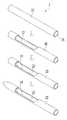
도 1은 종래 봉합침 제조방법을 설명하기 위한 도면이고, 도 2는 도 1에 의해 제조된 봉합침의 일부 사시도이다.FIG. 1 is a view for explaining a conventional sewing needle manufacturing method, and FIG. 2 is a partial perspective view of a sewing needle manufactured by FIG.
먼저, 길이방향으로 관통공(16)이 형성된 파이프(10)를 준비하여 선단부에 가까운 부위의 파이프(10)를 연삭해서 관통공(16)과 연통되는 인출홈(12)을 형성한다.First, a
다음 선단부의 관통공(16)을 통해 파이프(10)의 내부에 가이드봉(14)을 삽입한 상태에서(가이드봉의 후단부가 인출홈으로 됨) 선단부의 파이프(10)와 가이드봉(14)을 함께 용접한 다음 바렐(barrel) 작업을 통해 표면을 매끄럽게 연마하여 도 2와 같은 봉합침(1)을 제조한다.The
그런데 이와 같은 종래의 봉합침 제조방법은 숫돌 따위로 일일이 파이프의 표면을 갈아 인출홈을 형성하는 연삭과 용접을 해야 하므로 제조 공정이 느리고 그만큼 생산성이 떨어져 제조비용이 상승하는 문제점이 있었다.However, in the conventional method of manufacturing a suture needle, since the surface of the pipe is ground by grinding, it is necessary to perform welding with the grinding to form the drawing groove, so that the manufacturing process is slow and the productivity is low.
본 발명은 상술한 문제점을 해결하기 위하여 안출된 것으로서, 연삭이나 용접 등을 거치지 않고 순송형 스탬핑(progressive stamping) 금형에 드로잉, 벤딩, 포밍 등의 성형공정을 거쳐서 봉합침을 자동으로 제조하므로 제조 공정이 빠르고 그만큼 생산성을 향상시켜 봉합침을 저렴하게 생산할 수 있는 봉합침 제조방법 및 그 봉합침을 제공하는데 있다.SUMMARY OF THE INVENTION The present invention has been made in order to solve the above-mentioned problems, and it is an object of the present invention to provide a method of manufacturing a suture needle by automatically forming a suture needle through a forming process such as drawing, bending, and forming, on a progressive stamping die without grinding, And to provide a method of manufacturing a suture needle capable of producing a suture needle at a low cost by improving productivity as much as possible.
상술한 목적을 달성하기 위한 본 발명의 실시예에 따른 봉합침 제조방법은, 순송형 스탬핑(progressive stamping) 금형으로 편편한 판재(20)를 다수의 단계를 거쳐 성형하여 봉합침을 제조하는 것을 특징으로 한다.In order to accomplish the above object, a method of manufacturing a suture needle according to an embodiment of the present invention is characterized in that a
또한, 상기 다수의 단계는,The plurality of steps may further include:
(a) 편편한 판재(20)를 1차 블랭킹(blanking)하여 가헤드부와 가연결부 및 몸통부를 형성하는 단계;(a) blanking a
(b) 상기 가헤드부의 일부분을 드로잉(drawing)하여 오목한 홈을 형성하는 단계;(b) drawing the portion of the head portion to form a concave groove;
(c) 상기 가헤드부와 가연결부를 2차 블랭킹하여 헤드부와 연결부를 형성하는 단계;(c) forming a head portion and a connection portion by secondarily blanking the head portion and the fused portion;
(d) 상기 헤드부와 연결부의 일부분을 엠보싱(embossing)하여 스토퍼를 형성하는 단계;(d) embossing a portion of the head portion and the connection portion to form a stopper;
(e) 상기 헤드부와 연결부 및 몸통부를 벤딩(bending)하여 상기 헤드부를 가이드가 구비된 선단부가 되도록 하는 단계; 및(e) bending the head portion, the connecting portion, and the body portion so that the head portion is a tip portion provided with a guide; And
(f) 상기 연결부의 일부분을 노치(notch)하여 U자나 V자 형으로 오목하게 형성하는 단계;(f) forming a U-shaped or V-shaped concave portion by notching a portion of the connecting portion;
인 것을 특징으로 한다..
또한, 상기 (b)단계에서 형성된 오목한 홈은 상기 (e)단계에서 형성된 선단부의 첨단이 되고, 상기 (d)단계에서 연결부에 형성된 스토퍼는 상기 (e)단계에서 형성된 가이드를 지지하는 것을 특징으로 한다.In addition, the concave groove formed in the step (b) may be the tip of the tip formed in the step (e), and the stopper formed in the connecting part in the step (d) may support the guide formed in the step (e) do.
그리고 상기 (e)단계는 가이드가 될 헤드부와 몸통부를 순차적으로 벤딩하는 단계와, 선단부의 첨단이 될 드로잉 헤드부를 90도로 벤딩하여 몸통부와 일직선이 되도록 하는 단계와, 몸통부 및 가이드를 최종적 형상으로 완성시키는 벤딩 단계로 이루어지는 것을 특징으로 한다.The step (e) includes sequentially bending the head and the body to be a guide, bending the drawing head to be a tip of the leading end by 90 degrees and aligning the body with the body, And a bending step of completing the bending step.
본 발명의 실시예에 따른 봉합침은 상술한 방법에 의해 제조된 것으로, 상기 선단부와 몸통부가 연결부를 통해 연결되고, 상기 몸통부에 형성된 관통공이 연결부에 형성된 인출홈과 연통되며, 상기 선단부에 연결부를 향해 가이드가 경사지게 연장 형성되어 그 단부가 연결부에 형성된 스토퍼에 의해 지지되는 것을 특징으로 한다.The sewing needle according to the embodiment of the present invention is manufactured by the above-described method, and the front end portion and the body portion are connected through a connecting portion, the through hole formed in the body portion communicates with a drawing groove formed in the connecting portion, And the end portion of the guide is supported by a stopper formed on the connecting portion.
또한, 상기 선단부의 첨단 형상은 V자형이거나 U자형인 것을 특징으로 한다.Further, the leading end of the tip portion may be V-shaped or U-shaped.
그리고 상기 첨단 형상이 U자형인 선단부는 봉합사의 밸런스를 맞추기 위해 인출홈이 형성된 방향으로 절곡된 것을 특징으로 한다.The distal end of the U-shaped tip is bent in a direction in which the lead-out groove is formed in order to balance the suture.
상술한 과제의 해결 수단에 의하면, 연삭이나 용접 등의 공정을 거치지 않고 순송형 스탬핑(progressive stamping) 금형에 의해 드로잉, 벤딩, 포밍 등의 성형공정을 거쳐서 봉합침을 자동으로 제조하므로 제조 공정이 빠르고 그만큼 생산성을 향상시켜 봉합침을 저렴하게 생산할 수 있다.According to the means for solving the above-mentioned problems, since the sealing needles are automatically manufactured through a molding process such as drawing, bending, and forming by a progressive stamping die without going through a process such as grinding or welding, the manufacturing process is fast The sewing needle can be produced at low cost by improving productivity.
도 1은 종래 봉합침 제조방법을 설명하기 위한 도면이다.
도 2는 도 1에 의해 제조된 봉합침의 일부 사시도이다.
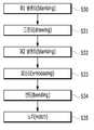
도 3은 본 발명의 실시예에 따른 봉합침 제조방법을 나타내는 순서도이다.
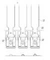
도 4a 내지 도 4f는 도 3의 제조 공정별 도면이다.
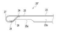
도 5는 본 발명의 실시예에 적용되는 봉합침의 전개도이다.
도 6a 내지 도 6d는 본 발명의 실시예에 의해 제조된 봉합침의 정면도이다.1 is a view for explaining a conventional sewing needle manufacturing method.
Figure 2 is a partial perspective view of the suture made by Figure 1;
3 is a flowchart showing a method of manufacturing a suture needle according to an embodiment of the present invention.
FIGS. 4A to 4F are views of the manufacturing process of FIG. 3. FIG.
5 is a developed view of a suture needle applied to an embodiment of the present invention.
6A to 6D are front views of a suturing needle manufactured by an embodiment of the present invention.
이하 본 발명의 실시예에 대하여 첨부된 도면을 참고로 그 구성 및 작용을 설명하기로 한다.DETAILED DESCRIPTION OF THE PREFERRED EMBODIMENTS Hereinafter, embodiments of the present invention will be described with reference to the accompanying drawings.
도면들 중 동일한 구성요소들에 대해서는 비록 다른 도면상에 표시되더라도 가능한 한 동일한 참조번호 및 부호들로 나타내고 있음에 유의해야 한다.It is to be noted that the same components of the drawings are denoted by the same reference numerals and symbols as possible even if they are shown in different drawings.
하기에서 본 발명을 설명함에 있어, 관련된 공지 기능 또는 구성에 대한 구체적인 설명이 본 발명의 요지를 불필요하게 흐릴 수 있다고 판단되는 경우에는 그 상세한 설명을 생략할 것이다.In the following description of the present invention, a detailed description of known functions and configurations incorporated herein will be omitted when it may make the subject matter of the present invention rather unclear.
또한, 어떤 부분이 어떤 구성요소를 "포함"한다고 할 때, 이는 특별히 반대되는 기재가 없는 한 다른 구성요소를 제외하는 것이 아니라 다른 구성요소를 더 포함할 수 있는 것을 의미한다.Also, when a part is referred to as " including " an element, it does not exclude other elements unless specifically stated otherwise.
도 3은 본 발명의 실시예에 따른 봉합침 제조방법을 나타내는 순서도이고, 도 4a 내지 도 4f는 도 3의 제조 공정별 도면이다.FIG. 3 is a flowchart showing a method of manufacturing a suture needle according to an embodiment of the present invention, and FIGS. 4A to 4F are views of the manufacturing process of FIG.
본 발명의 실시예에 따르면 순송형 스탬핑(progressive stamping) 금형으로 편편한 판재를 다수의 공정으로 성형하여 봉합침을 일체로 제조한다.According to an embodiment of the present invention, a flat plate material is formed by a progressive stamping die into a plurality of processes to produce a sealing needle integrally.
이를 좀 더 자세히 설명하면 먼저, 편편한 판재(20)를 순송형 스탬핑 금형의 펀치와 다이 사이에 올려놓고 전단용력을 가함으로써 판재(20)를 절단하는 1차 블랭키(blanking)에 의해 도 4a와 같이 점선으로 표시한 스크랩(21)을 차례로 제거함으로써 가헤드부(22')와 가연결부(25') 및 몸통부(23)를 형성한다(S30).4A and 4B by means of a primary blanking operation in which the
다음 도 4b에 도시된 바와 같이, 가헤드부(22')에 작은 점선의 원으로 표시한 부분을 펀치로 드로잉(drawing)하여 오목한 홈(이 오목한 홈은 후에 완성된 봉합침(20")의 선단부(27)의 첨단이 됨)을 형성한다(S31).As shown in FIG. 4B, a portion of the head portion 22 'indicated by a small dotted circle is drawn by a punch to form a concave groove (this concave groove is a part of the finished sealing
다음 오목한 홈이 형성된 가헤드부(22')와 가연결부(25')를 절단하는 2차 블랭킹에 의해 도 4c와 같이 점선으로 표시한 스크랩(21)을 차례로 제거함으로써 헤드부(22)와 연결부(25)를 형성한다(S32).The
이때 가연결부(25')는 몸통부(23)보다 좁게 타발된다.At this time, the fused portion 25 'is punched narrower than the
다음 도 4d에 도시된 바와 같이, 헤드부(22)와 연결부(25)에 점선으로 표시한 부분을 엠보싱(embossing) 처리하여 돌출시킴으로써 스토퍼(24)(상기 스토퍼(24)는 완성된 봉합침(20)에서 선단부(27)가 뒤로 밀리지 않게 지지함)를 형성한다(S33).4D, embossing and protruding portions of the
이와 같이 하여 도 5와 같은 중간 과정의 봉합침(20')이 완성된다.In this way, the sealing needle 20 'of the intermediate process as shown in FIG. 5 is completed.
이 중간 과정의 봉합침(20')은 헤드부(22)와 연결부(25) 및 몸통부(23)를 구비하고, 헤드부(22)에는 오목한 홈과 스토퍼(24)가, 연결부(25)에는 스토퍼(24)가 형성된다.The sewing needle 20 'of this intermediate process has a
다음 도 4e에 도시된 바와 같이, 헤드부(22)와 연결부(25) 및 몸통부(23)에 점선으로 표시된 부분을 차례로 벤딩(bending) 하여 헤드부(22)를 가이드(26)를 갖는 선단부(27)가 되도록 한다(S34).As shown in FIG. 4E, the
상기 S34 단계는 가이드(26)가 될 헤드부(22)와 몸통부(23)를 순차적으로 벤딩하는 단계와, 선단부(27)의 첨단이 될 드로잉 헤드부(22)를 90도로 벤딩하여 몸통부(23)와 일직선이 되도록 하는 단계와, 몸통부(23) 및 가이드(26)를 최종적 형상으로 완성시키는 벤딩 단계로 이루어진다.The step S34 includes sequentially bending the
그리고 도 4f에 되시된 바와 같이, 연결부(25)에 점선으로 표시된 부분을 노치(notch)하여 U자나 V자 형으로 오목하게 한다(S35).Then, as shown in FIG. 4F, the portion indicated by the dotted line in the connecting
마지막으로 이와 같은 중간 과정의 봉합침(20')을 잘라서 따로따로 분리한 후, 길이방향의 가운데를 기준으로 반원형으로 포밍(forming)하여 도 6a 내지 도 6c와 같은 봉합침(20")을 완성한다.Finally, the intermediate needle 20 'is cut and separated in a semi-circular shape with respect to the center in the longitudinal direction to complete the suture needle 20' 'as shown in FIGS. 6A to 6C do.
도 6a 내지 도 6d는 본 발명의 실시예에 의해 제조된 봉합침의 정면도이다.6A to 6D are front views of a suturing needle manufactured by an embodiment of the present invention.
도 6a 내지 도 6c에 도시된 바와 같이, 봉합침(20")은 선단부(27)와 연결부(25) 및 몸통부(23)를 포함하여 구성된다.As shown in Figs. 6A to 6C, the sealing
즉, 선단부(27)와 몸통부(23)가 연결부(25)를 통해 연결되며, 이때 상기 몸통부(23)에는 길이방향을 따라 관통공(23a)이 형성되어 연결부(25)에 형성된 인출홈(25a)과 연통된다.The
이를 통해 관통공(23a)에 미도시된 봉합사가 끼워진 후 인출홈(25a)을 통해 밖으로 인출된다.And the suture not shown in the through
또한, 상기 선단부(27)는 연결부(25)를 향해 가이드(26)가 경사지게 연장 형성되어 그 단부가 스토퍼(24)에 의해 지지되어 뒤로 밀리지 않는다.The
이때 선단부(27)의 첨단 형상은 도 6a와 같이 V자형으로 날카롭게 형성할 수도 있고, 도 6b와 같이 U자형으로 둥글게 형성할 수도 있다.At this time, the tip end of the
또한, 도 6c와 같이 도 6b의 형상에서 관통공(23a)에 끼워진 후 인출홈(25a)을 통해 밖으로 인출되는 봉합사의 밸런스를 맞추기 위해 선단부(27)를 인출홈(25a)이 형성된 아래로 경사지게 절곡할 수도 있다.6B, in order to balance the suture drawn out through the
그리고 도 6d와 같이 상기 S33 단계를 거치지 않아 스토퍼(24)를 형성하지 않고 선단부(27)의 첨단이 작으면서 가이드(26)를 짧게 형성할 수도 있다.As shown in FIG. 6D, the
이상에서 본 발명에 대한 기술 사상을 첨부 도면과 함께 서술하였지만, 이는 본 발명의 바람직한 실시 예를 예시적으로 설명한 것이지 본 발명을 한정하는 것은 아니다.Although the preferred embodiments of the present invention have been disclosed for illustrative purposes, those skilled in the art will appreciate that various modifications, additions and substitutions are possible, without departing from the scope and spirit of the invention as disclosed in the accompanying claims.
또한, 이 기술 분야의 통상의 지식을 가진 자라면 누구나 본 발명의 기술 사상의 범주를 이탈하지 않는 범위 내에서 다양한 변형 및 모방이 가능함은 명백한 사실이다.In addition, it is a matter of course that various modifications and variations are possible without departing from the scope of the technical idea of the present invention by anyone having ordinary skill in the art.
20: 판재20": 봉합침
21: 스크랩22: 헤드부
23: 몸통부24: 스토퍼
25: 연결부26: 가이드
27: 선단부20:
21: scrap 22: head part
23: body portion 24: stopper
25: connection 26: guide
27:
Claims (7)
Translated fromKorean상기 다수의 단계는,
(a) 편편한 판재(20)를 1차 블랭킹(blanking)하여 가헤드부(22')와 가연결부(25') 및 몸통부(23)를 형성하는 단계;
(b) 상기 가헤드부(22')의 일부분을 드로잉(drawing)하여 오목한 홈을 형성하는 단계;
(c) 상기 가헤드부(22')와 가연결부(25')를 2차 블랭킹하여 헤드부(22)와 연결부(25)를 형성하는 단계;
(d) 상기 헤드부(22)와 연결부(25)의 일부분을 엠보싱(embossing)하여 스토퍼(24)를 형성하는 단계;
(e) 상기 헤드부(22)와 연결부(25) 및 몸통부(23)를 벤딩(bending)하여 상기 헤드부(22)를 가이드(26)가 구비된 선단부(27)가 되도록 하는 단계; 및
(f) 상기 연결부(25)의 일부분을 노치(notch)하여 U자나 V자 형으로 오목하게 형성하는 단계;
인 것을 특징으로 하는 봉합침 제조방법.The method according to claim 1,
The plurality of steps including:
(a) blanking the flat plate member 20 to form a head portion 22 ', a fused portion 25' and a body portion 23;
(b) drawing the portion of the head portion 22 'to form a concave groove;
(c) forming a head part (22) and a connection part (25) by secondary blanking the head part (22 ') and the fused part (25');
(d) embossing a portion of the head portion 22 and the connection portion 25 to form a stopper 24;
(e) bending the head part 22, the connecting part 25 and the body part 23 so that the head part 22 becomes the tip part 27 provided with the guide 26; And
(f) forming a U-shaped or V-shaped concave portion by notching a portion of the connecting portion 25;
Wherein the suture is made of a synthetic resin.
상기 (b)단계에서 형성된 오목한 홈은 상기 (e)단계에서 형성된 선단부(27)의 첨단이 되고, 상기 (d)단계에서 연결부(25)에 형성된 스토퍼(24)는 상기 (e)단계에서 형성된 가이드(26)를 지지하는 것을 특징으로 하는 봉합침 제조방법.3. The method of claim 2,
The concave groove formed in the step (b) becomes the tip of the tip portion 27 formed in the step (e), and the stopper 24 formed on the connection part 25 in the step (d) And the guide (26) is supported.
상기 (e)단계는 가이드(26)가 될 헤드부(22)와 몸통부(23)를 순차적으로 벤딩하는 단계와, 선단부(27)의 첨단이 될 드로잉 헤드부(22)를 90도로 벤딩하여 몸통부(23)와 일직선이 되도록 하는 단계와, 몸통부(23) 및 가이드(26)를 최종적 형상으로 완성시키는 벤딩 단계로 이루어지는 것을 특징으로 하는 봉합침 제조방법.3. The method of claim 2,
The step (e) includes sequentially bending the head part 22 and the body part 23 to be the guide 26 and bending the drawing head part 22 to be the tip of the leading end part 27 by 90 degrees And a bending step of completing the body portion (23) and the guide (26) in a final shape.
상기 선단부(27)와 몸통부(23)가 연결부(25)를 통해 연결되고, 상기 몸통부(23)에 형성된 관통공(23a)이 연결부(25)에 형성된 인출홈(25a)과 연통되며, 상기 선단부(27)에 연결부(25)를 향해 가이드(26)가 경사지게 연장 형성되어 그 단부가 연결부(25)에 형성된 스토퍼(24)에 의해 지지되는 것을 특징으로 하는 봉합침.3. A composition according to claim 2,
The front end portion 27 and the body portion 23 are connected to each other through a connecting portion 25 and a through hole 23a formed in the body portion 23 communicates with an outgoing groove 25a formed in the connecting portion 25, Wherein a guide (26) extends obliquely toward the connection part (25) at the distal end part (27) and the end of the guide part (26) is supported by a stopper (24) formed on the connection part (25).
상기 선단부(27)의 첨단 형상은 V자형이거나 U자형인 것을 특징으로 하는 봉합침.6. The method of claim 5,
Wherein the distal end portion (27) is V-shaped or U-shaped.
상기 첨단 형상이 U자형인 선단부(27)는 봉합사의 밸런스를 맞추기 위해 인출홈(25a)이 형성된 방향으로 절곡된 것을 특징으로 하는 봉합침.The method according to claim 6,
And the distal end portion (27) having a U-shaped tip is bent in a direction in which the lead-out groove (25a) is formed in order to balance the suture.
Priority Applications (1)
| Application Number | Priority Date | Filing Date | Title |
|---|---|---|---|
| KR1020170146477AKR20190051144A (en) | 2017-11-06 | 2017-11-06 | Suture needle manufacturing Method and the suture needle |
Applications Claiming Priority (1)
| Application Number | Priority Date | Filing Date | Title |
|---|---|---|---|
| KR1020170146477AKR20190051144A (en) | 2017-11-06 | 2017-11-06 | Suture needle manufacturing Method and the suture needle |
Publications (1)
| Publication Number | Publication Date |
|---|---|
| KR20190051144Atrue KR20190051144A (en) | 2019-05-15 |
Family
ID=66579392
Family Applications (1)
| Application Number | Title | Priority Date | Filing Date |
|---|---|---|---|
| KR1020170146477AAbandonedKR20190051144A (en) | 2017-11-06 | 2017-11-06 | Suture needle manufacturing Method and the suture needle |
Country Status (1)
| Country | Link |
|---|---|
| KR (1) | KR20190051144A (en) |
Citations (1)
| Publication number | Priority date | Publication date | Assignee | Title |
|---|---|---|---|---|
| KR100997186B1 (en) | 2008-06-02 | 2010-11-29 | (주)에스엠이엔지 | Manufacturing method of suture needle |
- 2017
- 2017-11-06KRKR1020170146477Apatent/KR20190051144A/ennot_activeAbandoned
Patent Citations (1)
| Publication number | Priority date | Publication date | Assignee | Title |
|---|---|---|---|---|
| KR100997186B1 (en) | 2008-06-02 | 2010-11-29 | (주)에스엠이엔지 | Manufacturing method of suture needle |
Similar Documents
| Publication | Publication Date | Title |
|---|---|---|
| AU2020203009B2 (en) | Suture and method for producing same | |
| JP6410980B2 (en) | A suture that does not require a knot work and a kit including the suture | |
| JP5506383B2 (en) | Sutures for wound suturing, tissue placement, tissue support, tissue suspension, and / or tissue fixation | |
| AU769895B2 (en) | Surgical methods using one-way suture | |
| US20180303477A1 (en) | Method of improving elasticity of tissue of living body | |
| US20120053603A1 (en) | Wound closure clips, systems and methods | |
| US10178990B2 (en) | Apparatus for inserting surgical thread, and surgical procedure kit for inserting surgical thread comprising same | |
| KR20160107580A (en) | The kit which using a stitching fiber and method thereof | |
| TWI623296B (en) | Dual needle set having single or multiple gold threads for hair loss treatment | |
| KR102307404B1 (en) | Suture for surgical and facial lift | |
| KR20190050055A (en) | Suture | |
| KR101965730B1 (en) | Suture manufacturing method and the suture | |
| KR20190051144A (en) | Suture needle manufacturing Method and the suture needle | |
| JP3868410B2 (en) | Suture with needle | |
| KR101709041B1 (en) | Double eyelid surgery System with Suture separation device | |
| KR20180133113A (en) | Needle assembly for face lifting | |
| KR20190031859A (en) | Biodegradable Suture having Retainers and the method thereof | |
| CN221555758U (en) | Anastomotic nail | |
| KR20230171775A (en) | Medical suture | |
| CN117883235A (en) | Three-needle eye bionic double eyelid operation | |
| JP2005304990A (en) | Suture needle |
Legal Events
| Date | Code | Title | Description |
|---|---|---|---|
| A201 | Request for examination | ||
| PA0109 | Patent application | Patent event code:PA01091R01D Comment text:Patent Application Patent event date:20171106 | |
| PA0201 | Request for examination | ||
| E902 | Notification of reason for refusal | ||
| PE0902 | Notice of grounds for rejection | Comment text:Notification of reason for refusal Patent event date:20181109 Patent event code:PE09021S01D | |
| E701 | Decision to grant or registration of patent right | ||
| PE0701 | Decision of registration | Patent event code:PE07011S01D Comment text:Decision to Grant Registration Patent event date:20190329 | |
| PG1501 | Laying open of application | ||
| PC1904 | Unpaid initial registration fee |