KR20190043327A - A light signal processing apparatus and method thereof - Google Patents
A light signal processing apparatus and method thereofDownload PDFInfo
- Publication number
- KR20190043327A KR20190043327AKR1020170135241AKR20170135241AKR20190043327AKR 20190043327 AKR20190043327 AKR 20190043327AKR 1020170135241 AKR1020170135241 AKR 1020170135241AKR 20170135241 AKR20170135241 AKR 20170135241AKR 20190043327 AKR20190043327 AKR 20190043327A
- Authority
- KR
- South Korea
- Prior art keywords
- cell
- gas
- intensity
- optical signal
- transmission signal
- Prior art date
- Legal status (The legal status is an assumption and is not a legal conclusion. Google has not performed a legal analysis and makes no representation as to the accuracy of the status listed.)
- Granted
Links
- 238000000034methodMethods0.000titleclaimsabstractdescription26
- 238000012545processingMethods0.000titleabstractdescription50
- 230000003287optical effectEffects0.000claimsabstractdescription136
- 230000005540biological transmissionEffects0.000claimsabstractdescription64
- 230000001678irradiating effectEffects0.000claimsabstractdescription9
- 238000010438heat treatmentMethods0.000claimsdescription29
- 239000003513alkaliSubstances0.000claimsdescription15
- 229910052756noble gasInorganic materials0.000claimsdescription10
- 239000000463materialSubstances0.000claimsdescription5
- 230000035699permeabilityEffects0.000claimsdescription4
- 238000004590computer programMethods0.000claims1
- 239000007789gasSubstances0.000description89
- IJGRMHOSHXDMSA-UHFFFAOYSA-NAtomic nitrogenChemical compoundN#NIJGRMHOSHXDMSA-UHFFFAOYSA-N0.000description17
- 238000010521absorption reactionMethods0.000description17
- IGLNJRXAVVLDKE-UHFFFAOYSA-Nrubidium atomChemical compound[Rb]IGLNJRXAVVLDKE-UHFFFAOYSA-N0.000description13
- 229910052701rubidiumInorganic materials0.000description12
- 238000010586diagramMethods0.000description11
- 229910052724xenonInorganic materials0.000description11
- FHNFHKCVQCLJFQ-UHFFFAOYSA-Nxenon atomChemical compound[Xe]FHNFHKCVQCLJFQ-UHFFFAOYSA-N0.000description11
- 229910052757nitrogenInorganic materials0.000description7
- XKRFYHLGVUSROY-UHFFFAOYSA-NArgonChemical compound[Ar]XKRFYHLGVUSROY-UHFFFAOYSA-N0.000description4
- 230000007423decreaseEffects0.000description3
- 230000010355oscillationEffects0.000description3
- 230000010287polarizationEffects0.000description3
- 229910052786argonInorganic materials0.000description2
- 229910052792caesiumInorganic materials0.000description2
- TVFDJXOCXUVLDH-UHFFFAOYSA-Ncaesium atomChemical compound[Cs]TVFDJXOCXUVLDH-UHFFFAOYSA-N0.000description2
- 238000004891communicationMethods0.000description2
- 229910052734heliumInorganic materials0.000description2
- 239000001307heliumSubstances0.000description2
- SWQJXJOGLNCZEY-UHFFFAOYSA-Nhelium atomChemical compound[He]SWQJXJOGLNCZEY-UHFFFAOYSA-N0.000description2
- 238000012986modificationMethods0.000description2
- 230000004048modificationEffects0.000description2
- 229910052754neonInorganic materials0.000description2
- GKAOGPIIYCISHV-UHFFFAOYSA-Nneon atomChemical compound[Ne]GKAOGPIIYCISHV-UHFFFAOYSA-N0.000description2
- 238000009530blood pressure measurementMethods0.000description1
- 230000003247decreasing effectEffects0.000description1
- 238000007599dischargingMethods0.000description1
- 229920001971elastomerPolymers0.000description1
- 238000005516engineering processMethods0.000description1
- 239000011521glassSubstances0.000description1
- 238000004519manufacturing processMethods0.000description1
- 229910000595mu-metalInorganic materials0.000description1
- 238000005086pumpingMethods0.000description1
- 239000005060rubberSubstances0.000description1
- 239000012780transparent materialSubstances0.000description1
- 230000007723transport mechanismEffects0.000description1
Images


Classifications
- G—PHYSICS
- G01—MEASURING; TESTING
- G01L—MEASURING FORCE, STRESS, TORQUE, WORK, MECHANICAL POWER, MECHANICAL EFFICIENCY, OR FLUID PRESSURE
- G01L11/00—Measuring steady or quasi-steady pressure of a fluid or a fluent solid material by means not provided for in group G01L7/00 or G01L9/00
- G01L11/02—Measuring steady or quasi-steady pressure of a fluid or a fluent solid material by means not provided for in group G01L7/00 or G01L9/00 by optical means
- G—PHYSICS
- G01—MEASURING; TESTING
- G01L—MEASURING FORCE, STRESS, TORQUE, WORK, MECHANICAL POWER, MECHANICAL EFFICIENCY, OR FLUID PRESSURE
- G01L15/00—Devices or apparatus for measuring two or more fluid pressure values simultaneously
Landscapes
- Physics & Mathematics (AREA)
- General Physics & Mathematics (AREA)
- Investigating Or Analysing Materials By Optical Means (AREA)
Abstract
Description
Translated fromKorean본 개시는 투과 신호로부터 가스의 압력과 관련된 정보를 획득 또는 처리하는 장치 및 그 방법에 관한 것이다.The present disclosure relates to an apparatus and method for obtaining or processing information relating to the pressure of a gas from a transmitted signal.
가스의 압력을 측정하는 다양한 기법들이 존재한다. 가스 압력의 측정을 위해서 통상적으로 이용되는 방법 중 하나는 방전을 이용하는 방법이다. 예를 들면, 공간을 두고 배치된 두 개의 전극에 높은 전압을 걸어서 전극간에 전류가 흐르도록 함으로써, 가스의 압력이 측정될 수 있다. 그러나 방전을 이용해서 가스의 압력을 측정하는 방법은 전극에 가하는 전압이 충분히 높아야 한다는 단점이 있다. 또한, 방전 개시 전압을 낮추기 위해서는 전극간의 간격이 충분히 좁아야 하기 때문에 방전을 이용해 가스의 압력을 측정하는 방법은 가스 압력 측정 장치를 실제로 구현하는데 불편함이 따른다는 단점이 있다.There are various techniques for measuring gas pressure. One of the methods conventionally used for measuring the gas pressure is a method using a discharge. For example, the gas pressure can be measured by applying a high voltage to two electrodes arranged in a space to allow a current to flow between the electrodes. However, the method of measuring the gas pressure using the discharge has a drawback that the voltage applied to the electrode must be sufficiently high. Further, since the gap between the electrodes must be sufficiently narrow to lower the discharge start voltage, there is a disadvantage in that the method of measuring the gas pressure using the discharge is inconvenient to actually implement the gas pressure measurement device.
따라서, 보다 간편한 방법으로 가스의 압력을 결정할 수 있는 방법 및 장치가 요구된다.Therefore, there is a need for a method and apparatus that can determine the pressure of the gas in a simpler manner.
일 실시 예는, 투과 신호로부터 가스의 압력과 관련된 정보를 획득 또는 처리하는 장치 및 그 방법을 개시한다. 구체적으로 가스를 투과한 광 신호를 센싱하여 가스의 압력을 결정하는 방법이 개시된다.One embodiment discloses an apparatus and method for obtaining or processing information related to the pressure of a gas from a transmission signal. Specifically, a method for determining the pressure of a gas by sensing an optical signal transmitted through a gas is disclosed.
상술한 기술적 과제를 달성하기 위한 기술적 수단으로서, 본 발명의 제 1 측면은 시간의 흐름에 따라 주파수가 달라지는 광 신호를 제 1 가스를 포함하는 제 1 셀 및 제 2 가스를 포함하는 제 2 셀에 조사하는 광원; 상기 제 1 셀을 투과한 제 1 투과 신호를 획득하는 제 1 광 센서; 상기 제 2 셀을 투과한 제 2 투과 신호를 획득하는 제 2 광 센서; 및 주파수 변화에 따른 상기 제 1 투과 신호의 세기와 주파수 변화에 따른 상기 제 2 투과 신호의 세기의 비교 결과에 기초하여 상기 제 2 가스의 압력을 결정하는 프로세서를 포함하는 장치를 제공할 수 있다.According to a first aspect of the present invention, there is provided a method for driving an optical signal having a frequency varying with time in a first cell including a first gas and a second cell including a second gas, A light source for irradiation; A first optical sensor for acquiring a first transmission signal transmitted through the first cell; A second optical sensor for acquiring a second transmission signal transmitted through the second cell; And a processor for determining the pressure of the second gas based on a comparison result of the intensity of the first transmission signal according to the frequency change and the intensity of the second transmission signal according to the frequency variation.
또한, 상기 프로세서는 상기 주파수 변화에 따른 상기 제 1 투과 신호의 세기와 주파수 변화에 따른 상기 광 신호의 세기간의 차이 및 상기 주파수 변화에 따른 상기 제 2 투과 신호의 세기와 주파수 변화에 따른 상기 광 신호의 세기간의 차이의 비교 결과에 기초하여 상기 제 2 가스의 압력을 결정할 수 있다.In addition, the processor may be configured to determine a difference between the intensity of the first transmission signal according to the frequency change and the intensity of the optical signal according to the frequency change, the intensity of the second transmission signal according to the frequency variation, The pressure of the second gas can be determined based on the comparison result of the difference between the intensities of the first gas and the second gas.
또한, 상기 제 1 가스는 알칼리 가스를 포함할 수 있다.In addition, the first gas may include an alkali gas.
또한, 상기 제 2 가스는 알칼리 가스, 노블 가스 및 버퍼 가스 중 적어도 하나를 포함할 수 있다.Further, the second gas may include at least one of an alkali gas, a noble gas, and a buffer gas.
또한, 상기 제 1 셀 및 상기 제 2 셀 중 적어도 하나는 자기장의 투과량을 감소시키는 차폐통에 포함될 수 있다.Also, at least one of the first cell and the second cell may be included in a shielding container that reduces the amount of magnetic field transmission.
또한, 상기 차폐통의 재질은 기설정된 값 이상의 투자율을 가질 수 있다.In addition, the material of the shield can have a permeability higher than a predetermined value.
또한, 상기 차폐통은 상기 제 1 셀 또는 상기 제 2 셀 내의 가스의 온도를 높이는 가열 장치를 포함할 수 있다.In addition, the shield can include a heating device for increasing the temperature of the gas in the first cell or the second cell.
또한, 상기 가열 장치는 2개 이상의 열선을 이용하여 각각의 열선으로부터 발생하는 자기장을 상호 상쇄시키는 트위스트 열선을 포함할 수 있다.In addition, the heating device may include a twisted hot wire that mutually offset the magnetic fields generated from the respective hot wires by using two or more hot wires.
또한, 상기 프로세서는 상기 비교 결과에 따라 결정되는 주파수 변이 및 로렌지안 선폭 중 적어도 하나에 따라 상기 제 2 가스의 압력을 결정할 수 있다.Also, the processor may determine the pressure of the second gas according to at least one of the frequency shift and the Lorentzian line width determined according to the comparison result.
본 발명의 제 2 측면은 시간의 흐름에 따라 주파수가 달라지는 광 신호를 제 1 가스를 포함하는 제 1 셀 및 제 2 가스를 포함하는 제 2 셀에 조사하는 단계; 상기 제 1 셀을 투과한 제 1 투과 신호를 획득하는 단계; 상기 제 2 셀을 투과한 제 2 투과 신호를 획득하는 단계; 및 주파수 변화에 따른 상기 제 1 투과 신호의 세기와 주파수 변화에 따른 상기 제 2 투과 신호의 세기의 비교 결과에 기초하여 상기 제 2 가스의 압력을 결정하는 단계를 포함하는 방법을 제공할 수 있다.According to a second aspect of the present invention, there is provided a method of manufacturing a light emitting device, comprising: irradiating an optical signal whose frequency varies with time to a first cell including a first gas and a second cell including a second gas; Acquiring a first transmission signal transmitted through the first cell; Acquiring a second transmission signal transmitted through the second cell; And determining a pressure of the second gas based on a comparison result of the intensity of the first transmission signal according to the frequency change and the intensity of the second transmission signal according to the frequency variation.
또한, 상기 제 2 가스의 압력을 결정하는 단계는 상기 주파수 변화에 따른 상기 제 1 투과 신호의 세기와 주파수 변화에 따른 상기 광 신호의 세기간의 차이 및 상기 주파수 변화에 따른 상기 제 2 투과 신호의 세기와 주파수 변화에 따른 상기 광 신호의 세기간의 차이의 비교 결과에 기초하여 상기 제 2 가스의 압력을 결정하는 단계를 포함할 수 있다.The step of determining the pressure of the second gas may further include determining a difference between the intensity of the optical signal according to the intensity of the first transmission signal and the intensity of the optical signal according to the frequency change, And determining the pressure of the second gas based on a comparison result of the difference between the intensities of the optical signals according to the frequency change.
본 발명의 제 3 측면은 제 2 측면의 방법을 컴퓨터에서 실행시키기 위한 프로그램을 기록한 컴퓨터로 읽을 수 있는 기록매체를 제공할 수 있다.The third aspect of the present invention can provide a computer-readable recording medium on which a program for causing a computer to execute the method of the second aspect is recorded.
본 발명의 제 4 측면은 시간의 흐름에 따라 주파수가 달라지는 광 신호를 빔 가르개에 조사하는 광원; 상기 빔 가르개로부터 출력되는 제 1 광이 제 1 가스를 포함하는 제 1 셀을 투과하여 획득되는 제 1 투과 신호를 획득하는 제 1 광 센서; 상기 빔 가르개로부터 출력되는 제 2 광이 제 2 가스를 포함하는 제 2 셀을 투과하여 획득되는 제 2 투과 신호를 획득하는 제 2 광 센서; 상기 빔 가르개로부터 출력되는 제 3 광으로부터 비투과 신호를 획득하는 제 3 광 센서; 및 주파수 변화에 따른 상기 제 1 투과 신호의 세기와 주파수 변화에 따른 상기 비투과 신호의 세기간의 차이 및 주파수 변화에 따른 상기 제 2 투과 신호의 세기와 주파수 변화에 따른 상기 비투과 신호의 세기간의 차이의 비교 결과에 기초하여 상기 제 2 가스의 압력을 결정하는 프로세서를 포함하는 장치를 제공할 수 있다.According to a fourth aspect of the present invention, there is provided a light source comprising: a light source for irradiating an optical signal whose frequency varies with time, A first photosensor for acquiring a first transmissive signal obtained by transmitting first light output from the beam gauge through a first cell comprising a first gas; A second photosensor for acquiring a second transmissive signal obtained by transmitting a second light output from the beam gauge through a second cell comprising a second gas; A third photosensor for acquiring a non-transmissive signal from the third light output from the beam grating; And a difference between the intensity of the first transmission signal according to the frequency change and the intensity of the non-transmission signal according to the frequency variation and the difference between the intensity of the second transmission signal and the intensity of the non- And a processor for determining the pressure of the second gas based on the result.
도 1은 일 실시 예에 따른 광 신호 처리 장치의 구성의 일 예를 나타내는 블록도이다.
도 2는 일 실시 예에 따라 광 신호를 이용하여 동작하는 자이로스코프의 일 예를 나타내는 도면이다.
도 3은 일 실시 예에 따라 셀을 투과한 투과 신호를 이용하여 가스의 압력을 결정하는 광 신호 처리 장치의 일 예를 나타내는 블록도이다.
도 4는 일 실시 예에 따라 복수개의 셀에 대해서 투과 신호를 비교하는 일 예를 나타내는 도면이다.
도 5는 일 실시 예에 따라 셀을 투과한 신호와 셀을 투과하지 않은 신호를 이용하여 가스의 압력을 결정하는 광 신호 처리 장치의 일 예를 나타내는 블록도이다.
도 6은 일 실시 예에 따라 제 1 셀 및 제 2 셀에 광 신호를 조사하여 가스의 압력을 결정하는 방법을 나타내는 흐름도이다.
도 7은 일 실시 예에 따른 트위스트 열선을 나타내는 도면이다.1 is a block diagram showing an example of a configuration of an optical signal processing apparatus according to an embodiment.
2 is a diagram showing an example of a gyroscope operating using an optical signal according to an embodiment.
3 is a block diagram showing an example of an optical signal processing apparatus for determining a gas pressure using a transmission signal transmitted through a cell according to an embodiment.
4 is a diagram illustrating an example of comparing transmission signals with respect to a plurality of cells according to an embodiment.
5 is a block diagram showing an example of an optical signal processing apparatus for determining a gas pressure using a signal transmitted through a cell and a signal not transmitted through a cell according to an embodiment.
6 is a flowchart illustrating a method of determining gas pressure by irradiating an optical signal to a first cell and a second cell according to an embodiment.
7 is a view of a twisted hot wire according to one embodiment.
이하 첨부된 도면을 참조하면서 오로지 예시를 위한 실시 예들을 상세히 설명하기로 한다. 하기 실시 예는 기술적 사상을 구체화하기 위한 것일 뿐 권리범위를 제한하거나 한정하는 것이 아님은 물론이다. 상세한 설명 및 실시 예로부터 해당 기술분야에 속하는 전문가가 용이하게 유추할 수 있는 것은 권리범위에 속하는 것으로 해석된다.DETAILED DESCRIPTION OF THE PREFERRED EMBODIMENTS Hereinafter, exemplary embodiments of the present invention will be described in detail with reference to the accompanying drawings. It is to be understood that the following embodiments are intended to illustrate the technical idea and are not intended to limit or limit the scope of rights. It is to be understood that within the scope of the appended claims, those skilled in the art will readily conceive from the description and the examples.
본 명세서에서 사용되는 “구성된다” 또는 “포함한다” 등의 용어는 명세서 상에 기재된 여러 구성 요소들, 도는 여러 단계들을 반드시 모두 포함하는 것으로 해석되지 않아야 하며, 그 중 일부 구성 요소들 또는 일부 단계들은 포함되지 않을 수도 있고, 또는 추가적인 구성 요소 또는 단계들을 더 포함할 수 있는 것으로 해석되어야 한다. 또한, 명세서에 기재된 "...부", "모듈" 등의 용어는 적어도 하나의 기능이나 동작을 처리하는 단위를 의미하며, 이는 하드웨어 또는 소프트웨어로 구현되거나 하드웨어와 소프트웨어의 결합으로 구현될 수 있다.As used herein, the term " comprises " or " comprising " or the like should not be construed as necessarily including all the various elements or steps described in the specification, May not be included, or may be interpreted to include additional components or steps. Also, the terms " part, " " module, " and the like described in the specification mean units for processing at least one function or operation, which may be implemented in hardware or software or a combination of hardware and software .
또한, 본 명세서에서 사용되는 “제 1” 또는 “제 2” 등과 같이 서수를 포함하는 용어는 다양한 구성 요소들을 설명하는데 사용할 수 있지만, 이러한 용어들은 하나의 구성 요소를 다른 구성 요소로부터 구별하거나 설명의 편의를 위한 목적으로 사용될 수 있다.It is also to be understood that terms including ordinals such as " first " or " second ", as used herein, may be used to describe various components, but such terms may be used to distinguish one component from another, It can be used for convenience.
이하에서는 도면을 참조하여 실시 예들을 상세히 설명한다.Hereinafter, embodiments will be described in detail with reference to the drawings.
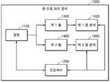
도 1은 일 실시 예에 따른 광 신호 처리 장치(1000)의 구성의 일 예를 나타내는 블록도이다.1 is a block diagram showing an example of a configuration of an optical
도 1에 도시된 바와 같이, 일 실시 예에 따른 광 신호 처리 장치(1000)는 광원(1100), 프로세서(1200), 제 1 광 센서(1500) 및 제 2 광 센서(1600)를 포함할 수 있다. 또한 다른 실시 예에 따라 광 신호 처리 장치(1000)는 제 1 셀(1300) 및 제 2 셀(1400)을 더 포함할 수 있다. 그러나, 도 1에 도시된 구성요소들 외에 다른 범용적인 구성요소들이 광 신호 처리 장치(1000)에 더 포함될 수 있음을 관련 기술 분야에서 통상의 지식을 가진 자라면 이해할 수 있다. 또는 다른 실시 예에 따를 경우, 도 1에 도시된 구성요소들 중 일부 구성요소는 생략될 수 있음을 관련 기술 분야에서 통상의 지식을 가진 자라면 이해할 수 있다.1, an optical
일 실시 예에 따른 광원(1100)은 광 신호를 셀에 조사할 수 있다.A
셀은 기설정된 형상의 차폐통를 포함할 수 있다. 예를 들면, 셀은 내부가 비어 있는 직육면체 형상의 차폐통일 수 있다. 셀은 투명한 재질(예: 유리)로 구성될 수 있다.The cell may include a shielding container of a predetermined shape. For example, the cell may be a rectangular parallelepiped shielding enclosure with an empty interior. The cell can be made of a transparent material (eg glass).
일 실시 예에 따른 광원(1100)이 조사하는 광 신호의 주파수는 시간의 흐름에 따라 달라질 수 있다. 예를 들면, 광원(1100)은 시간의 흐름에 따라 주파수가 증가 또는 감소하는 레이저를 조사할 수 있다. 다른 예로, 광원(1100)은 시간의 흐름에 따라 주파수의 증가와 감소가 반복되는 레이저를 조사할 수 있다. 다른 예로, 광원(1100)은 최대값과 최대값의 사이에서 주파수가 변하는 레이저를 조사할 수 있다.The frequency of the optical signal irradiated by the
광원(1100)은 복수개의 셀에 광 신호를 조사할 수 있다.The
예를 들면, 광원(1100)은 제 1 셀(1300) 및 제 2 셀(1400)에 광 신호를 조사할 수 있다. 이 경우, 광 신호 처리 장치(1000)는 광 신호가 제 1 셀(1300)을 투과하여 획득되는 제 1 투과 신호와, 광 신호가 제 2 셀(1400)을 투과하여 획득되는 제 2 투과 신호를 획득할 수 있다.For example, the
다른 예로, 광원(1100)는 제 1 셀(1300), 제 2 셀(1400) 및 셀이 없는 공간에 광 신호를 조사할 수 있다. 이 경우, 광 신호 처리 장치(1000)는 광 신호가 제 1 셀(1300)을 투과하여 획득되는 제 1 투과 신호와, 광 신호가 제 2 셀(1400)을 투과하여 획득되는 제 2 투과 신호와 셀을 투과하지 않은 광 신호인 비투과 신호를 획득할 수 있다.As another example, the
광원(1100)으로부터 광 신호가 조사되는 셀은 가스를 포함할 수 있다. 예를 들면, 제 1 셀(1300)은 알칼리 가스를 포함할 수 있다. 일 예로, 제 1 셀(1300)은 세슘(Cs) 가스를 포함할 수 있다. 또는 제 1 셀(1300)은 루비듐(Rb) 가스를 포함할 수 있다. 다른 예로, 제 2 셀(1400)은 알칼리 가스, 노블 가스 및 버퍼 가스 중 적어도 하나를 포함할 수 있다. 노블 가스는 헬륨, 네온, 아르곤, 제논 등을 포함할 수 있다. 버퍼 가스는 질소 등을 포함할 수 있다. 그러나 제 1 셀(1300) 또는 제 2 셀(1400)에 포함될 수 있는 가스는 상술된 기재에 제한되지 않는다.The cell to which the optical signal is irradiated from the
셀은 자기장의 투과량을 감소시키는 자기장 차폐통에 포함될 수 있다. 예를 들면, 제 1 셀(1300) 및 제 2 셀(1400) 중 적어도 하나는 자기장 차폐통 내에 위치할 수 있다. 자기장 차폐통은 셀로 인가되는 자기장을 감소시킬 수 있다. 자기장 차폐통의 재질은 기설정된 값 이상의 투자율을 가지는 재질일 수 있다.The cell may be included in a magnetic shielding cylinder that reduces the transmission of the magnetic field. For example, at least one of the
셀 내에는 가열 장치가 포함될 수 있다. 예를 들면, 제 1 셀(1300)에는 제 1 가열 장치가 포함되고, 제 2 셀에는 제 2 가열 장치가 포함될 수 있다. 일 실시 예에 따른 가열 장치는 셀 내의 가스의 온도를 높일 수 있다. 예를 들면, 프로세서(1200)는 제 1 셀(1300) 내에 포함된 제 1 가스의 온도를 제 1 가열 장치를 이용하여 높일 수 있다. 다른 예로, 프로세서(1200)는 제 2 셀(1400) 내에 포함된 제 2 가스의 온도를 제 2 가열 장치를 이용하여 높일 수 있다.A heating device may be included in the cell. For example, the
자기장 차폐통 내에는 가열 장치가 포함될 수 있다. 예를 들면, 제 1 셀(1300)을 포함하는 제 1 자기장 차폐통에는 제 1 가열 장치가 포함되고, 제 2 셀(1400)을 포함하는 제 2 자기장 차폐통에는 제 2 가열 장치가 포함될 수 있다. 가열 장치는 셀 내의 가스의 온도를 높일 수 있다.A heating device may be included in the magnetic field shielding container. For example, a first heating device may be included in the first magnetic shielding barrel including the
가열 장치는 하나 이상의 열선을 포함할 수 있다. 예를 들면, 가열 장치는 트위스트 열선을 포함할 수 있다. 트위스트 열선은 2개 이상의 열선을 이용하여 열선으로부터 발생하는 자기장을 상호 상쇄시킬 수 있다. 트위스트 열선의 일 예는 도 7을 참조할 수 있다. 가열 장치는 온도가 높아짐에 따라 증가하는 원자의 증기압을 이용하여 더 많은 원자들이 흡수 분광 신호에 참여하도록 할 수 있다.The heating device may include one or more heat wires. For example, the heating device may include a twisted hot wire. The twisted hot wire can mutually offset the magnetic field generated from the hot wire by using two or more hot wires. An example of a twisted hot wire can be found in FIG. The heating device can utilize the vapor pressure of the atoms to increase as the temperature increases, allowing more atoms to participate in the absorption spectroscopic signal.
일 실시 예에 따른 광원(1100)은 레이저 다이오드를 포함할 수 있다. 예를 들면 광원(1100)은 주파수 제어가 가능한 내부 혹은 외부 공진기형 레이저 다이오드를 포함할 수 있다. 일 예로, 광원(1100)은 내부 공진기형 레이저 다이오드 일 수 있다. DBR 또는 DFB 레이저 다이오드는 전류의 변화에 따라 레이저 발진 주파수의 제어 또는 주사가 가능할 수 있다. 광원(1100)으로 DBR 또는 DFB 레이저 다이오드가 이용되는 경우, 광 신호 처리 장치(1000)는 레이저 세기의 변화를 보상하기 위해서 복수개의 광 센서에서 획득한 광 신호의 차이 값을 이용하여 가스 압력을 결정할 수 있다.The
일 실시 예에 따른 광원(1100)은 레이저를 조사할 수 있다. 예를 들면 광원(1100)은 선형 편광 레이저빔을 조사할 수 있다.The
일 실시 예에 따른 광 센서는 광 신호를 획득할 수 있다. 일 실시 예에 따른 광 센서는 포토 다이오드를 포함할 수 있다.An optical sensor according to an embodiment can acquire an optical signal. An optical sensor according to one embodiment may comprise a photodiode.
일 실시 예에 따른 광 신호 처리 장치(1000)는 복수개의 광 센서를 포함할 수 있다. 예를 들면, 광 신호 처리 장치(1000)는 제 1 광 센서(1500) 및 제 2 광 센서(1600)를 포함할 수 있다.The optical
제 1 광 센서(1500) 및 제 2 광 센서(1600)는 각각 광 신호를 획득할 수 있다. 예를 들면, 제 1 광 센서(1500)는 제 1 셀을 투과한 제 1 투과 신호를 획득할 수 있다. 다른 예로, 제 2 광 센서(1600)는 제 2 셀(1400)을 투과한 제 2 투과 신호를 획득할 수 있다.The first
일 실시 예에 따른 프로세서(1200)는 광 신호 처리 장치(1000)에 포함된 각 구성을 제어할 수 있다. 또한, 일 실시 예에 따른 프로세서(1200)는 광 신호 처리를 통해 가스의 압력을 결정할 수 있다.The
일 실시 예에 따른 프로세서(1200)는 주파수 변화에 따른 제 1 투과 신호의 세기와 주파수 변화에 따른 제 2 투과 신호의 세기의 비교 결과에 기초하여 제 2 가스의 압력을 결정할 수 있다. 제 1 투과 신호는 광원(1100)으로부터 조사된 광 신호가 제 1 셀(1300)을 투과하여 제 1 광 센서(1500)에서 획득되는 광 신호일 수 있다. 제 2 투과 신호는 광원(1100)으로부터 조사된 광 신호가 제 2 셀(1400)을 투과하여 제 2 광 센서(1600)에서 획득되는 광 신호일 수 있다. 제 1 셀과 제 2 셀에는 기설정된 가스가 포함될 수 있다. 예를 들면, 제 1 셀(1300)에는 알칼리 가스가 포함되고, 제 2 셀(1400)에는 알칼리 가스, 노블 가스 및 버퍼 가스가 포함될 수 있다. 이 경우, 프로세서(1200)는 알칼리 가스가 포함된 제 1 셀(1300)을 투과한 광 신호인 제 1 투과 신호의 세기와 알칼리 가스, 노블 가스 및 버퍼 가스가 포함된 제 2 셀(1400)을 투과한 광 신호인 제 2 투과 신호의 세기를 비교하여 제 2 셀(1400)에 포함된 가스의 압력을 결정할 수 있다.The
일 실시 예에 따른 프로세서(1200)는 주파수 변화에 따른 제 1 투과 신호의 세기와 주파수 변화에 따른 광 신호의 세기간의 차이 및 주파수 변화에 따른 제 2 투과 신호의 세기와 주파수 변화에 따른 광 신호의 세기간의 차이의 비교 결과에 기초하여 제 2 가스의 압력을 결정할 수 있다.The
제 1 광 센서(1500)는 제 1 투과 신호를 획득하고, 제 2 광 센서(1600)는 제 2 투과 신호를 획득할 수 있다. 광원(1100)에서 조사하는 광 신호의 주파수가 시간의 흐름에 따라 변하는 경우, 프로세서(1200)는 광원(1100)에서 조사하는 광 신호의 주파수 변화에 따른 제 1 투과 신호의 세기 변화 및 광원(1100)에서 조사하는 광 신호의 주파수 변화에 따른 제 2 투과 신호의 세기 변화를 획득할 수 있다. 일 실시 예에 따른 프로세서(1200)는 주파수 변화에 따른 제 1 투과 신호의 세기 변화와 광원(1100)에서 조사되는 광 신호의 주파수 변화에 따른 세기 변화의 차이를 나타내는 제 1 그래프와 주파수 변화에 따른 제 2 투과 신호의 세기 변화와 광원(1100)에서 조사되는 광 신호의 주파수 변화에 따른 세기 변화의 차이를 나타내는 제 2 그래프의 비교 결과에 기초하여 제 2 가스의 압력을 결정할 수 있다. 예를 들면, 프로세서(1200)는 제 1 그래프와 제 2 그래프 간의 주파수 변이(예: 세기가 피크일 때 주파수 값의 변화 등) 또는 제 1 그래프와 제 2 그래프 간의 선폭(예: 로렌지안 선폭) 변화 등을 이용하여 제 2 가스의 압력을 결정할 수 있다.The
도 2는 일 실시 예에 따라 광 신호를 이용하여 동작하는 자이로스코프의 일 예를 나타내는 도면이다.2 is a diagram showing an example of a gyroscope operating using an optical signal according to an embodiment.
일 실시 예에 따른 원자 스핀 자이로스코프(200)(Atom Spin Gyroscope : ASG)는 알칼리 가스(예: 루비듐(87Rb 혹은 85Rb)), 노블가스( 예: 제논(129Xe 혹은 131Xe)), 버퍼 가스(예: 질소(N2)) 중 적어도 하나가 포함된 혼합 셀(103)에 양자축 정의를 위해 Z-축 방향으로 자기장을 걸어준 후 루비듐과 제논의 라모어(Larmor) 주파수를 측정함으로써 회전각 또는 회전각속도를 결정할 수 있다.The Atom Spin Gyroscope (ASG) 200 according to one embodiment can be used in combination with an alkaline gas such as rubidium (87Rb or 85Rb), a noble gas (such as xenon (129Xe or 131Xe) : Nitrogen (N2)), a magnetic field is applied in the Z-axis direction to define the quantum axis, and then the frequency of the rubbers of rubidium and xenon is measured to determine the rotation angle or rotation The angular velocity can be determined.
도 2를 참조하면, 원자 스핀 자이로스코프(200)의 일 예가 개시된다.Referring to FIG. 2, an example of an atomic-
도 2에 도시된 바와 같이, 일 실시 예에 따른 원자 스핀 자이로스코프(200)는 광학적 펌핑 및 검출에 사용하는 레이저 다이오드(101, 105), 편광판(102), 1/4 파장판(106), 혼합 셀(103), 편광 빔 가르개(109), 포토 다이오드(104, 110, 111), 양자축 DC 자기장 발생 코일(107), AC 자기장 발생 코일(108) 및 자기장 차폐통(112)를 포함할 수 있다. 그러나, 도 2에 도시된 구성요소들 외에 다른 범용적인 구성요소들이 원자 스핀 자이로스코프(200)에 더 포함될 수 있음을 관련 기술 분야에서 통상의 지식을 가진 자라면 이해할 수 있다. 또는 다른 실시 예에 따를 경우, 도 1에 도시된 구성요소들 중 일부 구성요소는 생략될 수 있음을 관련 기술 분야에서 통상의 지식을 가진 자라면 이해할 수 있다.2, the atomic-
일 실시 예에 따른 원자 스핀 자이로스코프(200)는 광 신호 처리 장치(1000)를 이용하여 동작할 수 있다. 구체적으로, 광원(1100)은 레이저 다이오드(101, 105), 제 1 셀(1300) 또는 제 2 셀(1400)은 혼합 셀(103), 제 1 광 센서(1500) 또는 제 2 광 센서(1600)는 포토 다이오드(104, 110, 111)에 각각 대응될 수 있다.The atomic spins gyroscope 200 according to one embodiment can operate using the optical
일 실시 예에 따를 때, 원자 스핀 자이로스코프(200)의 물리부를 구성하는 혼합 셀(103)에서 광학적으로 펌핑된 루비듐 원자들이 제논과의 스핀 교환 충돌로 스핀 정보가 제논으로 옮겨지게 되며, 이때 질소는 스핀 교환 구도에서 루비듐과 제논간의 광 펌핑을 도와주는 역할 및 제논이 셀 내의 벽과의 충돌로부터 스핀정보를 잃어버리지 않도록 도와주는 역할을 수행할 수 있다.According to one embodiment, the spin exchange information of the optically pumped rubidium atoms in the
또한 질소는 루비듐과 루비듐간의 충돌로 흥분상태에서 바닥상태로 떨어지며 발생하는 421nm 파장의 빛이 나오지 않도록 루비듐이 흥분 상태에 있을 때 질소 분자가 질소 분자의 회전에너지로 루비듐의 에너지를 흡수하여 루비듐의 상태를 빠르게 바닥 상태로 떨어지도록 한다. 이처럼 원자 스핀 자이로스코프(200)에서 각 가스들이 하는 역할이 매우 중요하며 혼합 셀(103) 내의 분압도 중요하다.In addition, when nitrogen is excited by rubidium so that light of 421 nm wavelength does not emerge when nitrogen collides with rubidium and rubidium, the nitrogen molecule absorbs the energy of rubidium by the rotation energy of nitrogen molecule, To quickly fall to the floor. In this way, the role of each gas in the
혼합 셀(103) 내의 각종 가스들의 분압을 결정하기 위해서는 원자 스핀 자이로스코프(200)를 구성하여 라모어 주파수 신호의 크기를 비교하거나 제논, 질소에 대한 방전개시전압, 전극 간 거리에 대한 파센(Paschen) 곡선을 이용할 수 있다.In order to determine the partial pressures of various gases in the
도 3은 일 실시 예에 따라 셀을 투과한 투과 신호를 이용하여 가스의 압력을 결정하는 광 신호 처리 장치(1000)의 일 예를 나타내는 블록도이다.3 is a block diagram illustrating an example of an optical
도 1에 도시된 바와 같이, 일 실시 예에 따른 광 신호 처리 장치(1000)는 레이저 다이오드(201), 광 아이솔레이터(optical isolator)(202), ND(Natural Density) 필터(203), 1/2 파장 판 (half wave plate)(204), 편광 빔 가르개 (polarization beam splitter)(205), 제 1 빔 가르개 (beam splitter)(206), 제 2 빔 가르개 (beam splitter)(215), 기준 셀(207), 혼합 셀(210), 제 1 포토 다이오드(208), 제 2 포토 다이오드(209), 제 3 포토 다이오드(211), 제 4 포토 다이오드(212), 제 1 자기장 차폐통(213) 및 제 2 자기장 차폐통(214)를 포함할 수 있다. 그러나, 도 3에 도시된 구성요소들 외에 다른 범용적인 구성요소들이 광 신호 처리 장치(1000)에 더 포함될 수 있음을 관련 기술 분야에서 통상의 지식을 가진 자라면 이해할 수 있다. 또는 다른 실시 예에 따를 경우, 도 3에 도시된 구성요소들 중 일부 구성요소는 생략될 수 있음을 관련 기술 분야에서 통상의 지식을 가진 자라면 이해할 수 있다.1, an optical
일 실시 예에 따를 때, 주파수 제어가 가능한 레이저 다이오드(201)가 조사하는 레이저 빔(예: 선형 편광 레이저 빔)은 광 아이솔레이터(202), ND 필터(203) 및 1/2 파장 판(204)을 통과하여 편광 빔 가르개(205)로 인가될 수 있다. 편광 빔 가르개(205)로 인가된 레이저 빔은 제 1 빔 가르개(206) 및 제 2 빔 가르개(215)로 인가될 수 있다. 제 1 빔 가르개(206)로 인가된 레이저 빔은 제 1 레이저 빔과 제 2 레이저 빔으로 나뉘고, 제 1 레이저 빔은 기준 셀(207)을 통과하여 제 1 포토 다이오드(208)로 인가되고, 제 2 레이저 빔은 제 2 포토 다이오드(209)로 인가될 수 있다. 제 2 빔 가르개(215)로 인가된 레이저 빔은 제 3 레이저 빔과 제 4 레이저 빔으로 나뉘고, 제 3 레이저 빔은 혼합 셀(210)을 통과하여 제 3 포토 다이오드(211)로 인가되고, 제 4 레이저 빔은 제 4 포토 다이오드(212)로 인가될 수 있다. 또한, 기준 셀(207)은 제 1 자기장 차폐통(213)에 포함되고, 혼합 셀(210)은 제 2 자기장 차폐통(214)에 포함될 수 있다.According to one embodiment, a laser beam (e.g., a linearly polarized laser beam) irradiated by a
제 1 빔 가르개(206) 및 제 2 빔 가르개(215)는 각각 기준 셀(207) 및 혼합 셀(210)의 앞에 위치하여 주파수 변화에 따라 달라지는 레이저 빔의 세기 변화의 결정에 이용될 수 있다. 일 예에 따를 때, 레이저 다이오드(201)는 DBR 또는 DFB 레이저 다이오드일 수 있다. 레이저 다이오드(201)는 전류 제어를 통해 레이저 발진 주파수를 제어 또는 주사할 수 있다. 레이저 다이오드(201)의 발진 주파수가 변하는 경우 레이저 다이오드(201)가 조사하는 레이저의 세기가 변할 수 있다. 레이저 다이오드(201)가 조사하는 레이저의 세기 변화를 보상하기 위해서 제 1 포토 다이오드(208)에서 수신한 신호의 세기와 제 2 포토 다이오드(209)에서 수신한 신호의 세기의 차이인 제 1 차이와, 제 3 포토 다이오드(211)에서 수신한 신호의 세기와 제 4 포토 다이오드(212)에서 수신한 신호의 세기의 차이인 제 2 차이가 이용될 수 있다. 광 신호 처리 장치(1000)는 ND 필터(203)를 이용해서 레이저 빔의 세기를 감소시킬 수 있다.The first beam gauges 206 and the second beam gauges 215 are located in front of the
기준 셀(207)은 제 1 자기장 차폐통(213)의 내에 위치시키고, 혼합 셀(210)은 제 2 자기장 차폐통(214)의 내에 위치시킬 수 있다. 제 1 자기장 차폐통(213) 및 제 2 자기장 차폐통(214)는 기준 셀(207) 또는 혼합 셀(210)에 대한 외부 자기장을 차단 또는 감소시킬 수 있다.The
자기장 차폐통은 자기장을 감소시킬 수 있는 재질로 구성될 수 있다. 예를 들면, 제 1 자기장 차폐통(213) 또는 제 2 자기장 차폐통(214)는 투자율이 높은 1겹 이상의 뮤 메탈(mu-metal)로 구성될 수 있다.The magnetic field shield can consist of a material that can reduce the magnetic field. For example, the first magnetic
또한, 자기장 차폐통에는 레이저빔이 지나갈 수 있는 영역이 포함될 수 있다. 예를 들면, 제 1 자기장 차폐통(213) 또는 제 2 자기장 차폐통(214)는 원통형이고, 윗 면과 밑 면에 레이저 빔이 지나갈 수 있는 구멍이 있을 수 있다.Further, the magnetic field shielding barrel may include a region through which the laser beam can pass. For example, the first magnetic-
자기장 차폐통 내에는 가열 장치가 포함될 수 있다. 예를 들면, 기준 셀(207)을 포함하는 제 1 자기장 차폐통(213)에는 제 1 가열 장치가 포함되고, 혼합 셀(110)을 포함하는 제 2 자기장 차폐통(214)에는 제 2 가열 장치가 포함될 수 있다. 가열 장치는 셀 내의 가스의 온도를 높일 수 있다.A heating device may be included in the magnetic field shielding container. For example, a first heating device is included in the first
가열 장치는 하나 이상의 열선을 포함할 수 있다. 예를 들면, 가열 장치는 트위스트 열선을 포함할 수 있다. 일 실시 예에 따른 트위스트 열선은 2개 이상의 열선을 이용하여 열선으로부터 발생하는 자기장을 상호 상쇄시킬 수 있다. 예를 들면, 트위스트 열선은 피복이 입혀진 열선을 서로 꼬아서 도선에 전류가 지나가면서 생기는 자기장을 서로 반대 방향으로 상쇄시킬 수 있다. 가열 장치는 온도가 높아짐에 따라 증가하는 원자의 증기압을 이용하여 더 많은 원자들이 흡수 분광 신호에 참여하도록 할 수 있다.The heating device may include one or more heat wires. For example, the heating device may include a twisted hot wire. The twisted hot wire according to one embodiment can mutually offset the magnetic fields generated from the hot wire by using two or more hot wires. For example, a twisted hot wire can twist the hot wires coated with each other to cancel the magnetic fields generated by passing current through the wires in opposite directions to each other. The heating device can utilize the vapor pressure of the atoms to increase as the temperature increases, allowing more atoms to participate in the absorption spectroscopic signal.
도 4는 일 실시 예에 따라 복수개의 셀에 대해서 투과 신호를 비교하는 일 예를 나타내는 도면이다.4 is a diagram illustrating an example of comparing transmission signals with respect to a plurality of cells according to an embodiment.
일 실시 예에 따른 광 신호 처리 장치(1000)는 광원(예: 레이저 다이오드)에서 조사된 광이 제 1 셀에서 흡수된 양을 주파수에 따라 결정할 수 있다. 예를 들면, 광 신호 처리 장치(1000)는 제 2 포토 다이오드(209)에서 획득한 레이저의 세기에서 제 1 포토 다이오드(208)에서 획득한 레이저의 세기를 빼서 기준 셀(207)에서 흡수된 제 1 흡수 신호(410)를 결정할 수 있다. 도 4에 도시된 바와 같이 제 1 흡수 신호(410)는 주파수에 따라 변할 수 있다. 다른 예로, 광 신호 처리 장치(1000)는 제 4 포토 다이오드(212)에서 획득한 레이저의 세기에서 제 3 포토 다이오드(211)에서 획득한 레이저의 세기를 빼서 혼합 셀(210)에서 흡수된 제 2 흡수 신호(420)를 결정할 수 있다. 도 4에 도시된 바와 같이 제 2 흡수 신호(420)는 주파수에 따라 변할 수 있다.The
일 실시 예에 따른 기준 셀(207)에는 알칼리 가스가 포함될 수 있다. 예를 들면, 기준 셀(207)에는 루비듐이 포함될 수 있다. 이 경우, 제 1 흡수 신호(410)는 루비듐에서 흡수된 신호를 나타낼 수 있다.The
일 실시 예에 따른 혼합 셀(210)에는 복수 개의 종류의 가스가 포함될 수 있다. 예를 들면, 혼합 셀(210)에는 제논 및 질소가 포함될 수 있다. 다른 예로, 혼합 셀(210)에는 루비듐, 제논 및 질소가 포함될 수 있다. 이 경우, 제 2 흡수 신호(420)는 혼합 셀에서 흡수된 신호를 나타낼 수 있다.A plurality of types of gases may be included in the mixing
도 4를 참조하면 가로 축은 주파수를 나타내고, 세로 축은 흡수 신호의 크기를 나타낼 수 있다.Referring to FIG. 4, the horizontal axis represents the frequency and the vertical axis represents the magnitude of the absorption signal.
도 4에서 확인할 수 있는 바와 같이 제 1 흡수 신호(410)와 제 2 흡수 신호(420)를 비교하면, 주파수 변이 및 선폭이 변경되었음을 확인할 수 있다.As shown in FIG. 4, when the
일 실시 예에 따른 광 신호 처리 장치(1000)는 [수학식 1]을 이용하여, 셀 내의 가스의 압력을 결정할 수 있다. 예를 들면, 광 신호 처리 장치(1000)는 [수학식 1]을 이용하여, 제 1 흡수 신호(410)와 제 2 흡수 신호(420) 간의 주파수 변이 및 로렌지안 선폭의 변화에 따라서 혼합 셀 내의 가스의 압력을 결정할 수 있다.The optical

[수학식 1]에서, δ는 주파수 변이, γL은 로렌지안 선폭, n은 초미세구조의 수, ai는 i번째 초미세구조들 간의 라인 스트렝스(line strength), V는 평준화된 보이트(voigt) 함수를 의미할 수 있다. 또한, c0, c1, c2, vi는 곡선 맞춤으로 획득될 상수로서, c0는 신호에서의 기준 전압, c1은 선형 증가할 때의 기준선, c2는 흡수상수, vi는 신호 중심을 나타낼 수 있다.(1), δ is the frequency variation, γL is the Laurentian linewidth, n is the number of ultrafine structures, ai is the line strength between the i th hyperfine structures, V is the leveled voigt, Function. Also, c0, c1, c2, and vi are constants to be obtained by curve fitting, c0 is the reference voltage in the signal, c1 is the reference line when linearly increasing, c2 is the absorption constant, and vi is the signal center.
위와 같이 광 신호 처리 장치(1000)는 혼합 셀의 흡수 신호를 측정하여 그 혼합 셀 내의 가스 분압을 결정할 수 있다. 광 신호 처리 장치(1000)는 방전을 위한 전극을 이용하지 않고 가스 압력 또는 분압을 결정할 수 있다.As described above, the optical
도 5는 일 실시 예에 따라 셀을 투과한 신호와 셀을 투과하지 않은 신호를 이용하여 가스의 압력을 결정하는 광 신호 처리 장치의 일 예를 나타내는 블록도이다.5 is a block diagram showing an example of an optical signal processing apparatus for determining a gas pressure using a signal transmitted through a cell and a signal not transmitted through a cell according to an embodiment.
도 5에 도시된 바와 같이, 일 실시 예에 따른 광 신호 처리 장치(1000)는 광원(1100), 프로세서(1200), 제 1 광 센서(1500), 제 2 광 센서(1600), 빔 가르개(510) 및 제 3 광 센서(520)를 포함할 수 있다. 또한 다른 실시 예에 따라 광 신호 처리 장치(1000)는 제 1 셀(1300) 및 제 2 셀(1400)을 더 포함할 수 있다. 그러나, 도 5에 도시된 구성요소들 외에 다른 범용적인 구성요소들이 광 신호 처리 장치(1000)에 더 포함될 수 있음을 관련 기술 분야에서 통상의 지식을 가진 자라면 이해할 수 있다. 또는 다른 실시 예에 따를 경우, 도 5에 도시된 구성요소들 중 일부 구성요소는 생략될 수 있음을 관련 기술 분야에서 통상의 지식을 가진 자라면 이해할 수 있다.5, an optical
일 실시 예에 따른 빔 가르개(510)는 광원(1100)으로부터 수신한 광을 나누어 전송할 수 있다. 예를 들면, 빔 가르개(510)는 광원(1100)으로부터 수신한 광을 나누어 제 1 셀(1300), 제 2 셀(1400) 및 제 3 광 센서(520)로 전송할 수 있다.The
일 실시 예에 따른 제 3 광 센서(520)는 셀을 거치지 않고 빔 가르개(510)로부터 바로 광을 수신할 수 있다. 이 경우 제 3 광 센서(520)는 셀을 투과하지 않은 비투과 신호를 수신할 수 있다.A third
광원(1100), 프로세서(1200), 제 1 광 센서(1500), 제 2 광 센서(1600), 제 1 셀(1300) 및 제 2 셀(1400)은 도 1에 개시된 내용을 참조할 수 있다.The
도 6은 일 실시 예에 따라 제 1 셀 및 제 2 셀에 광 신호를 조사하여 가스의 압력을 결정하는 방법을 나타내는 흐름도이다.6 is a flowchart illustrating a method of determining gas pressure by irradiating an optical signal to a first cell and a second cell according to an embodiment.
단계 S610에서 일 실시 예에 따른 광 신호 처리 장치(1000)는 시간의 흐름에 따라 주파수가 달라지는 광 신호를 제 1 가스를 포함하는 제 1 셀 및 제 2 가스를 포함하는 제 2 셀에 조사한다.In step S610, the optical
일 실시 예에 따른 광 신호 처리 장치(1000)가 조사하는 광 신호의 주파수는 시간의 흐름에 따라 달라질 수 있다. 예를 들면, 광 신호 처리 장치(1000)는 시간의 흐름에 따라 주파수가 증가 또는 감소하는 레이저를 조사할 수 있다. 다른 예로, 광 신호 처리 장치(1000)은 시간의 흐름에 따라 주파수의 증가와 감소가 반복되는 레이저를 조사할 수 있다. 다른 예로, 광 신호 처리 장치(1000)는 최대값과 최대값의 사이에서 주파수가 변하는 레이저를 조사할 수 있다.The frequency of the optical signal irradiated by the optical
광 신호 처리 장치(1000)는 복수개의 셀에 광 신호를 조사할 수 있다.The optical
예를 들면, 광 신호 처리 장치(1000)는 제 1 셀 및 제 2 셀에 광 신호를 조사할 수 있다. 다른 예로, 광 신호 처리 장치(1000)는 제 1 셀, 제 2 셀 및 셀이 없는 공간에 광 신호를 조사할 수 있다.For example, the optical
단계 S620에서 일 실시 예에 따른 광 신호 처리 장치(1000)는 제 1 셀을 투과한 제 1 투과 신호를 획득한다.In step S620, the optical
광 신호 처리 장치(1000)는 광 신호가 제 1 셀을 투과하여 획득되는 제 1 투과 신호를 획득할 수 있다. 제 1 셀은 가스를 포함할 수 있다. 예를 들면, 제 1 셀은 알칼리 가스를 포함할 수 있다. 일 예로, 제 1 셀은 세슘(Cs) 가스를 포함할 수 있다. 또는 제 1 셀은 루비듐(Rb) 가스를 포함할 수 있다.The optical
단계 S630에서 일 실시 예에 따른 광 신호 처리 장치(1000)는 제 2 셀을 투과한 제 2 투과 신호를 획득한다.In step S630, the optical
광 신호 처리 장치(1000)는 광 신호가 제 2 셀을 투과하여 획득되는 제 2 투과 신호를 획득할 수 있다. 제 2 셀은 가스를 포함할 수 있다. 예를 들면, 제 2 셀은 알칼리 가스, 노블 가스 및 버퍼 가스 중 적어도 하나를 포함할 수 있다. 노블 가스는 헬륨, 네온, 아르곤, 제논 등을 포함할 수 있다. 버퍼 가스는 질소 등을 포함할 수 있다.The optical
그러나 제 1 셀 또는 제 2 셀에 포함될 수 있는 가스는 상술된 기재에 제한되지 않는다.However, the gas that can be contained in the first cell or the second cell is not limited to the above description.
단계 S640에서 일 실시 예에 따른 광 신호 처리 장치(1000)는 주파수 변화에 따른 제 1 투과 신호의 세기와 주파수 변화에 따른 제 2 투과 신호의 세기의 비교 결과에 기초하여 제 2 가스의 압력을 결정한다.In step S640, the optical
제 1 투과 신호는 광원으로부터 조사된 광 신호가 제 1 셀을 투과하여 제 1 광 센서에서 획득되는 광 신호일 수 있다. 제 2 투과 신호는 광원으로부터 조사된 광 신호가 제 2 셀을 투과하여 제 2 광 센서에서 획득되는 광 신호일 수 있다. 제 1 셀과 제 2 셀에는 기설정된 가스가 포함될 수 있다. 예를 들면, 제 1 셀에는 알칼리 가스가 포함되고, 제 2 셀(1400)에는 알칼리 가스, 노블 가스 및 버퍼 가스가 포함될 수 있다. 일 실시 예에 따른 광 신호 처리 장치(1000)는 조사된 광 신호의 주파수 변화에 따른 제 1 투과 신호의 세기 변화와 조사된 광 신호의 주파수 변화에 따른 제 2 투과 신호의 세기 변화를 비교하여 제 2 셀의 압력 또는 분압을 결정할 수 있다.The first transmissive signal may be an optical signal that is emitted from the light source and transmitted through the first cell and obtained by the first photosensor. The second transmissive signal may be an optical signal transmitted by the light source and transmitted through the second cell and obtained by the second photosensor. A predetermined gas may be included in the first cell and the second cell. For example, the first cell may contain an alkali gas and the
도 7은 일 실시 예에 따른 트위스트 열선(700)을 나타내는 도면이다.7 is a diagram illustrating a twisted
일실시 예에 따른 트위스트 열선(700)은 2개 이상의 열선을 이용하여 열선으로부터 발생하는 자기장을 상호 상쇄시킬 수 있다. 예를 들면, 트위스트 열선(700)은 피복이 입혀진 열선을 서로 꼬아서 도선에 전류가 지나가면서 생기는 자기장을 서로 반대 방향으로 상쇄시킬 수 있다.The twisted
구체적으로 도 7을 참조하면, 트위스트 열선(700)을 구성하는 제 1 열선(710)과 제 2 열선(720)은 서로 꼬인 형태일 수 있다. 또한, 제 1 열선(710)과 제 2 열선(720)에서 발생하는 자기장은 상호 상쇄될 수 있다. 예를 들면, 제 1 열선(710)에서 전류가 흐름에 따라 발생하는 자기장과 제 2 열선(720)에서 전류가 흐름에 따라 발생하는 자기장이 상호 반대 방향인 경우, 제 1 열선(710)과 제 2 열선(720)에서 발생하는 자기장은 상호 상쇄될 수 있다.Specifically, referring to FIG. 7, the
본 발명의 일 실시예는 컴퓨터에 의해 실행되는 프로그램 모듈과 같은 컴퓨터에 의해 실행가능한 명령어를 포함하는 기록 매체의 형태로도 구현될 수 있다. 컴퓨터 판독 가능 매체는 컴퓨터에 의해 액세스될 수 있는 임의의 가용 매체일 수 있고, 휘발성 및 비휘발성 매체, 분리형 및 비분리형 매체를 모두 포함한다. 또한, 컴퓨터 판독가능 매체는 컴퓨터 저장 매체 및 통신 매체를 모두 포함할 수 있다. 컴퓨터 저장 매체는 컴퓨터 판독가능 명령어, 데이터 구조, 프로그램 모듈 또는 기타 데이터와 같은 정보의 저장을 위한 임의의 방법 또는 기술로 구현된 휘발성 및 비휘발성, 분리형 및 비분리형 매체를 모두 포함한다. 통신 매체는 전형적으로 컴퓨터 판독가능 명령어, 데이터 구조, 프로그램 모듈, 또는 반송파와 같은 변조된 데이터 신호의 기타 데이터, 또는 기타 전송 메커니즘을 포함하며, 임의의 정보 전달 매체를 포함한다.One embodiment of the present invention may also be embodied in the form of a recording medium including instructions executable by a computer, such as program modules, being executed by a computer. Computer readable media can be any available media that can be accessed by a computer and includes both volatile and nonvolatile media, removable and non-removable media. In addition, the computer-readable medium may include both computer storage media and communication media. Computer storage media includes both volatile and nonvolatile, removable and non-removable media implemented in any method or technology for storage of information such as computer readable instructions, data structures, program modules or other data. Communication media typically includes any information delivery media, including computer readable instructions, data structures, program modules, or other data in a modulated data signal such as a carrier wave, or other transport mechanism.
전술한 본 발명의 설명은 예시를 위한 것이며, 본 발명이 속하는 기술분야의 통상의 지식을 가진 자는 본 발명의 기술적 사상이나 필수적인 특징을 변경하지 않고서 다른 구체적인 형태로 쉽게 변형이 가능하다는 것을 이해할 수 있을 것이다. 그러므로 이상에서 기술한 실시예들은 모든 면에서 예시적인 것이며 한정적이 아닌 것으로 이해해야만 한다. 예를 들어, 단일형으로 설명되어 있는 각 구성 요소는 분산되어 실시될 수도 있으며, 마찬가지로 분산된 것으로 설명되어 있는 구성 요소들도 결합된 형태로 실시될 수 있다.It will be understood by those skilled in the art that the foregoing description of the present invention is for illustrative purposes only and that those of ordinary skill in the art can readily understand that various changes and modifications may be made without departing from the spirit or essential characteristics of the present invention. will be. It is therefore to be understood that the above-described embodiments are illustrative in all aspects and not restrictive. For example, each component described as a single entity may be distributed and implemented, and components described as being distributed may also be implemented in a combined form.
본 발명의 범위는 상기 상세한 설명보다는 후술하는 특허청구범위에 의하여 나타내어지며, 특허청구범위의 의미 및 범위 그리고 그 균등 개념으로부터 도출되는 모든 변경 또는 변형된 형태가 본 발명의 범위에 포함되는 것으로 해석되어야 한다.The scope of the present invention is defined by the appended claims rather than the detailed description and all changes or modifications derived from the meaning and scope of the claims and their equivalents are to be construed as being included within the scope of the present invention do.
101, 105: 레이저 다이오드
106: 1/4 파장판
102: 편광판
103: 혼합 셀
107: 양자축 DC 자기장 발생 코일
108: AC 자기장 발생 코일
109: 편광 빔 가르개
104, 110, 111: 포토 다이오드
112: 자기장 차폐통
200: 원자 스핀 자이로스코프
201: 레이저 다이오드
202: 광 아이솔레이터
203: ND 필터
204: 1/2 파장 판
205: 편광 빔 가르개
206: 제 1 빔 가르개
215: 제 2 빔 가르개
207: 기준 셀
208: 제 1 포토 다이오드
209: 제 2 포토 다이오드
211: 제 3 포토 다이오드
212: 제 4 포토 다이오드
210: 혼합 셀
213: 제 1 자기장 차폐통
214: 제 2 자기장 차폐통
410: 제 1 흡수 신호
420: 제 2 흡수 신호
510: 빔 가르개
520: 제 3 광 센서
700: 트위스트 열선
710: 제 1 열선
720: 제 2 열선
1000: 광 신호 처리 장치
1100: 광원
1200: 프로세서101, 105: laser diode
106: 1/4 wavelength plate
102: polarizer
103: Mixed cell
107: Quantum axis DC magnetic field generating coil
108: AC magnetic field generating coil
109: polarized beam
104, 110 and 111: photodiodes
112: magnetic field shielding barrel
200: Atomic spin gyroscope
201: Laser diode
202: optical isolator
203: ND filter
204: 1/2 wavelength plate
205: polarized beam
206: 1st beam beam
215: second beam beam
207: Reference cell
208: first photodiode
209: second photodiode
211: Third photodiode
212: fourth photodiode
210: Mixed cell
213: first magnetic field shielding barrel
214: second magnetic field shielding case
410: first absorption signal
420: second absorption signal
510: beam beam
520: Third optical sensor
700: Twisted hot wire
710: First heat line
720: Second heat line
1000: Optical signal processing device
1100: Light source
1200: Processor
Claims (13)
Translated fromKorean상기 제 1 셀을 투과한 제 1 투과 신호를 획득하는 제 1 광 센서;
상기 제 2 셀을 투과한 제 2 투과 신호를 획득하는 제 2 광 센서; 및
주파수 변화에 따른 상기 제 1 투과 신호의 세기와 주파수 변화에 따른 상기 제 2 투과 신호의 세기의 비교 결과에 기초하여 상기 제 2 가스의 압력을 결정하는 프로세서를 포함하는 장치.A light source for irradiating a first cell including a first gas and a second cell including a second gas with an optical signal whose frequency varies with time;
A first optical sensor for acquiring a first transmission signal transmitted through the first cell;
A second optical sensor for acquiring a second transmission signal transmitted through the second cell; And
And a processor for determining the pressure of the second gas based on a result of comparison between the intensity of the first transmission signal and the intensity of the second transmission signal in accordance with the frequency change.
상기 프로세서는
상기 주파수 변화에 따른 상기 제 1 투과 신호의 세기와 주파수 변화에 따른 상기 광 신호의 세기간의 차이 및 상기 주파수 변화에 따른 상기 제 2 투과 신호의 세기와 주파수 변화에 따른 상기 광 신호의 세기간의 차이의 비교 결과에 기초하여 상기 제 2 가스의 압력을 결정하는 장치.The method according to claim 1,
The processor
A difference between the intensity of the optical signal according to the intensity of the first transmission signal and the intensity of the optical signal according to the frequency change and the intensity of the optical signal according to the intensity of the second transmission signal and the intensity of the optical signal according to the frequency change, And to determine the pressure of the second gas based on the comparison result.
상기 제 1 가스는 알칼리 가스를 포함하는 장치.The method according to claim 1,
Wherein the first gas comprises an alkali gas.
상기 제 2 가스는 알칼리 가스, 노블 가스 및 버퍼 가스 중 적어도 하나를 포함하는 장치.The method according to claim 1,
Wherein the second gas comprises at least one of an alkali gas, a noble gas, and a buffer gas.
상기 제 1 셀 및 상기 제 2 셀 중 적어도 하나는 자기장의 투과량을 감소시키는 차폐통에 포함된 장치.The method according to claim 1,
Wherein at least one of the first cell and the second cell is included in a shielding container that reduces the amount of magnetic field transmission.
상기 차폐통의 재질은 기설정된 값 이상의 투자율을 갖는 장치.6. The method of claim 5,
Wherein the material of the shielding barrel has a permeability higher than a predetermined value.
상기 차폐통은 상기 제 1 셀 또는 상기 제 2 셀 내의 가스의 온도를 높이는 가열 장치를 포함하는 장치.6. The method of claim 5,
Wherein the shielding cylinder comprises a heating device for increasing the temperature of the gas in the first cell or the second cell.
상기 가열 장치는 2개 이상의 열선을 이용하여 각각의 열선으로부터 발생하는 자기장을 상호 상쇄시키는 트위스트 열선을 포함하는 장치.8. The method of claim 7,
Wherein the heating device comprises a twisted hot wire that mutually offset the magnetic field generated from each hot wire using two or more hot wires.
상기 프로세서는
상기 비교 결과에 따라 결정되는 주파수 변이 및 로레지안 선폭 중 적어도 하나에 따라 상기 제 2 가스의 압력을 결정하는 장치.The method according to claim 1,
The processor
And determining the pressure of the second gas according to at least one of the frequency shift and the row line width determined according to the comparison result.
상기 제 1 셀을 투과한 제 1 투과 신호를 획득하는 단계;
상기 제 2 셀을 투과한 제 2 투과 신호를 획득하는 단계; 및
주파수 변화에 따른 상기 제 1 투과 신호의 세기와 주파수 변화에 따른 상기 제 2 투과 신호의 세기의 비교 결과에 기초하여 상기 제 2 가스의 압력을 결정하는 단계를 포함하는 방법.Irradiating a first cell including a first gas and a second cell including a second gas with an optical signal whose frequency varies with time;
Acquiring a first transmission signal transmitted through the first cell;
Acquiring a second transmission signal transmitted through the second cell; And
Determining a pressure of the second gas based on a comparison of the intensity of the first transmission signal with the frequency change and the intensity of the second transmission signal according to the frequency variation.
상기 제 2 가스의 압력을 결정하는 단계는
상기 주파수 변화에 따른 상기 제 1 투과 신호의 세기와 주파수 변화에 따른 상기 광 신호의 세기간의 차이 및 상기 주파수 변화에 따른 상기 제 2 투과 신호의 세기와 주파수 변화에 따른 상기 광 신호의 세기간의 차이의 비교 결과에 기초하여 상기 제 2 가스의 압력을 결정하는 단계를 포함하는 방법.11. The method of claim 10,
The step of determining the pressure of the second gas
A difference between the intensity of the optical signal according to the intensity of the first transmission signal and the intensity of the optical signal according to the frequency change and the intensity of the optical signal according to the intensity of the second transmission signal and the intensity of the optical signal according to the frequency change, And determining the pressure of the second gas based on the comparison result.
상기 빔 가르개로부터 출력되는 제 1 광이 제 1 가스를 포함하는 제 1 셀을 투과하여 획득되는 제 1 투과 신호를 획득하는 제 1 광 센서;
상기 빔 가르개로부터 출력되는 제 2 광이 제 2 가스를 포함하는 제 2 셀을 투과하여 획득되는 제 2 투과 신호를 획득하는 제 2 광 센서;
상기 빔 가르개로부터 출력되는 제 3 광으로부터 비투과 신호를 획득하는 제 3 광 센서; 및
주파수 변화에 따른 상기 제 1 투과 신호의 세기와 주파수 변화에 따른 상기 비투과 신호의 세기간의 차이 및 주파수 변화에 따른 상기 제 2 투과 신호의 세기와 주파수 변화에 따른 상기 비투과 신호의 세기간의 차이의 비교 결과에 기초하여 상기 제 2 가스의 압력을 결정하는 프로세서를 포함하는 장치.A light source for irradiating a beam spot with an optical signal whose frequency varies with time;
A first photosensor for acquiring a first transmissive signal obtained by transmitting first light output from the beam gauge through a first cell comprising a first gas;
A second photosensor for acquiring a second transmissive signal obtained by transmitting a second light output from the beam gauge through a second cell comprising a second gas;
A third photosensor for acquiring a non-transmissive signal from the third light output from the beam grating; And
A difference between the intensity of the first transmission signal according to the frequency change and the intensity of the non-transmission signal according to the frequency change and the difference between the intensity of the second transmission signal according to the frequency variation and the intensity of the non- And determining a pressure of the second gas based on the pressure of the second gas.
Priority Applications (1)
| Application Number | Priority Date | Filing Date | Title |
|---|---|---|---|
| KR1020170135241AKR101985896B1 (en) | 2017-10-18 | 2017-10-18 | Light signal processing apparatus, method thereof and compture program stored in recording medium |
Applications Claiming Priority (1)
| Application Number | Priority Date | Filing Date | Title |
|---|---|---|---|
| KR1020170135241AKR101985896B1 (en) | 2017-10-18 | 2017-10-18 | Light signal processing apparatus, method thereof and compture program stored in recording medium |
Publications (2)
| Publication Number | Publication Date |
|---|---|
| KR20190043327Atrue KR20190043327A (en) | 2019-04-26 |
| KR101985896B1 KR101985896B1 (en) | 2019-06-04 |
Family
ID=66281411
Family Applications (1)
| Application Number | Title | Priority Date | Filing Date |
|---|---|---|---|
| KR1020170135241AActiveKR101985896B1 (en) | 2017-10-18 | 2017-10-18 | Light signal processing apparatus, method thereof and compture program stored in recording medium |
Country Status (1)
| Country | Link |
|---|---|
| KR (1) | KR101985896B1 (en) |
Cited By (1)
| Publication number | Priority date | Publication date | Assignee | Title |
|---|---|---|---|---|
| KR102104398B1 (en)* | 2019-07-22 | 2020-04-24 | 국방과학연구소 | An atomic spin gyroscope and a method for correcting a magnetic field gradient using the atomic spin gyroscope |
Citations (9)
| Publication number | Priority date | Publication date | Assignee | Title |
|---|---|---|---|---|
| JPS62217132A (en)* | 1985-12-30 | 1987-09-24 | テクノロジ− ダイナミツクス インコ−ポレ−テツド | Optical type pressure detection system |
| JPH04256816A (en)* | 1991-02-08 | 1992-09-11 | Fujitsu Ltd | Gas pressure measurement method and device |
| JPH08304203A (en)* | 1995-05-02 | 1996-11-22 | Hitachi Ltd | Optical pressure detecting method and its sensor, wavelength plate of optical pressure sensor, polarization selecting device and beam distributor, and optical pressure sensor system for multipoint measurement by the method and its sensing probe |
| JPH09304274A (en)* | 1996-05-10 | 1997-11-28 | Hitachi Cable Ltd | Optical gas concentration detection method and device |
| JP2001033331A (en)* | 1999-07-15 | 2001-02-09 | Yazaki Corp | Pressure sensor |
| JP2001518630A (en)* | 1997-09-26 | 2001-10-16 | ハリスピン ポラリズィーテ ガーセ ゲーエムベーハー | Magnetic shielding container |
| KR20090081705A (en)* | 2008-01-24 | 2009-07-29 | 성균관대학교산학협력단 | Optical sensor and mixed gas measurement method for mixed gas measurement |
| JP2011053142A (en)* | 2009-09-03 | 2011-03-17 | Nikon Corp | Wavelength detector, pressure detector, vibration isolator, and exposure system |
| WO2017089624A1 (en)* | 2015-11-29 | 2017-06-01 | Norwegian Sensors As | Optical pressure sensor |
- 2017
- 2017-10-18KRKR1020170135241Apatent/KR101985896B1/enactiveActive
Patent Citations (10)
| Publication number | Priority date | Publication date | Assignee | Title |
|---|---|---|---|---|
| JPS62217132A (en)* | 1985-12-30 | 1987-09-24 | テクノロジ− ダイナミツクス インコ−ポレ−テツド | Optical type pressure detection system |
| US4933545A (en)* | 1985-12-30 | 1990-06-12 | Metricor, Inc. | Optical pressure-sensing system using optical resonator cavity |
| JPH04256816A (en)* | 1991-02-08 | 1992-09-11 | Fujitsu Ltd | Gas pressure measurement method and device |
| JPH08304203A (en)* | 1995-05-02 | 1996-11-22 | Hitachi Ltd | Optical pressure detecting method and its sensor, wavelength plate of optical pressure sensor, polarization selecting device and beam distributor, and optical pressure sensor system for multipoint measurement by the method and its sensing probe |
| JPH09304274A (en)* | 1996-05-10 | 1997-11-28 | Hitachi Cable Ltd | Optical gas concentration detection method and device |
| JP2001518630A (en)* | 1997-09-26 | 2001-10-16 | ハリスピン ポラリズィーテ ガーセ ゲーエムベーハー | Magnetic shielding container |
| JP2001033331A (en)* | 1999-07-15 | 2001-02-09 | Yazaki Corp | Pressure sensor |
| KR20090081705A (en)* | 2008-01-24 | 2009-07-29 | 성균관대학교산학협력단 | Optical sensor and mixed gas measurement method for mixed gas measurement |
| JP2011053142A (en)* | 2009-09-03 | 2011-03-17 | Nikon Corp | Wavelength detector, pressure detector, vibration isolator, and exposure system |
| WO2017089624A1 (en)* | 2015-11-29 | 2017-06-01 | Norwegian Sensors As | Optical pressure sensor |
Cited By (1)
| Publication number | Priority date | Publication date | Assignee | Title |
|---|---|---|---|---|
| KR102104398B1 (en)* | 2019-07-22 | 2020-04-24 | 국방과학연구소 | An atomic spin gyroscope and a method for correcting a magnetic field gradient using the atomic spin gyroscope |
Also Published As
| Publication number | Publication date |
|---|---|
| KR101985896B1 (en) | 2019-06-04 |
Similar Documents
| Publication | Publication Date | Title |
|---|---|---|
| Tsigutkin et al. | Observation of a large atomic parity violation effect in ytterbium | |
| US8327686B2 (en) | Method and apparatus for the photo-acoustic identification and quantification of analyte species in a gaseous or liquid medium | |
| US10215816B2 (en) | Magnetic field measuring apparatus | |
| US9366735B2 (en) | Optical pumping magnetometer | |
| Perrella et al. | Dichroic two-photon rubidium frequency standard | |
| Castagna et al. | Measurement of longitudinal and transverse spin relaxation rates using the ground-state Hanle effect | |
| JP5720740B2 (en) | Quantum interferometers, atomic oscillators, and magnetic sensors | |
| JP6077050B2 (en) | Atomic sensor system | |
| US20160061913A1 (en) | Optically pumped atomic magnetometer and magnetic sensing method | |
| WO2015015628A1 (en) | Magnetic field measuring device | |
| US9110006B1 (en) | Frequency-feedback cavity enhanced spectrometer | |
| Terra et al. | An ultra-stable optical frequency standard for telecommunication purposes based upon the 5S1/2→ 5D5/2 two-photon transition in Rubidium | |
| US8183942B2 (en) | Atomic clock operating with helium 3 | |
| JP2018502289A (en) | Spectroscopic apparatus and spectral method | |
| Tsigutkin et al. | Parity violation in atomic ytterbium: Experimental sensitivity and systematics | |
| JP5717392B2 (en) | LIGHT SOURCE DEVICE AND IMAGING DEVICE USING THE SAME | |
| KR101985896B1 (en) | Light signal processing apparatus, method thereof and compture program stored in recording medium | |
| Xu et al. | On-site calibration of the Raman laser absolute frequency for atom gravimeters | |
| CN105991133A (en) | Coherent Population Beat Atomic Clock with Synchronous Coherent Light Field Excitation and Its Realization Method | |
| Lisowski et al. | Dark resonances as a probe for the motional state of a single ion | |
| CN103760135A (en) | Speed transfer laser spectrum measuring device and method of V-type energy level structure atoms | |
| JP2023021719A (en) | Quantum interference device, atomic oscillator and control method | |
| JP3631410B2 (en) | Gas cell type atomic oscillator | |
| JP2025034793A (en) | Optically excited magnetic sensor and magnetoencephalograph | |
| JP2024039319A (en) | Magnetic field measurement device |
Legal Events
| Date | Code | Title | Description |
|---|---|---|---|
| A201 | Request for examination | ||
| PA0109 | Patent application | Patent event code:PA01091R01D Comment text:Patent Application Patent event date:20171018 | |
| PA0201 | Request for examination | ||
| E902 | Notification of reason for refusal | ||
| PE0902 | Notice of grounds for rejection | Comment text:Notification of reason for refusal Patent event date:20181122 Patent event code:PE09021S01D | |
| PG1501 | Laying open of application | ||
| E701 | Decision to grant or registration of patent right | ||
| PE0701 | Decision of registration | Patent event code:PE07011S01D Comment text:Decision to Grant Registration Patent event date:20190501 | |
| GRNT | Written decision to grant | ||
| PR0701 | Registration of establishment | Comment text:Registration of Establishment Patent event date:20190529 Patent event code:PR07011E01D | |
| PR1002 | Payment of registration fee | Payment date:20190530 End annual number:3 Start annual number:1 | |
| PG1601 | Publication of registration | ||
| PR1001 | Payment of annual fee | Payment date:20220422 Start annual number:4 End annual number:4 | |
| PR1001 | Payment of annual fee | Payment date:20230421 Start annual number:5 End annual number:5 | |
| PR1001 | Payment of annual fee | Payment date:20240423 Start annual number:6 End annual number:6 | |
| PR1001 | Payment of annual fee | Payment date:20250429 Start annual number:7 End annual number:7 |