KR20190034725A - Unit for supporting substrate, Apparatus for treating substrate, and Method for treating substrate - Google Patents
Unit for supporting substrate, Apparatus for treating substrate, and Method for treating substrateDownload PDFInfo
- Publication number
- KR20190034725A KR20190034725AKR1020170123097AKR20170123097AKR20190034725AKR 20190034725 AKR20190034725 AKR 20190034725AKR 1020170123097 AKR1020170123097 AKR 1020170123097AKR 20170123097 AKR20170123097 AKR 20170123097AKR 20190034725 AKR20190034725 AKR 20190034725A
- Authority
- KR
- South Korea
- Prior art keywords
- substrate
- heating member
- temperature
- buffer
- module
- Prior art date
- Legal status (The legal status is an assumption and is not a legal conclusion. Google has not performed a legal analysis and makes no representation as to the accuracy of the status listed.)
- Granted
Links
- 239000000758substrateSubstances0.000titleclaimsabstractdescription215
- 238000000034methodMethods0.000titleclaimsabstractdescription68
- 238000010438heat treatmentMethods0.000claimsabstractdescription118
- 238000012545processingMethods0.000claimsabstractdescription38
- 230000000284resting effectEffects0.000claims1
- 239000000872bufferSubstances0.000description108
- 238000001816coolingMethods0.000description67
- 238000012546transferMethods0.000description37
- 239000007788liquidSubstances0.000description33
- 230000001681protective effectEffects0.000description22
- 238000012805post-processingMethods0.000description20
- 238000007781pre-processingMethods0.000description20
- 238000000576coating methodMethods0.000description19
- 238000004140cleaningMethods0.000description17
- 239000011248coating agentSubstances0.000description16
- 238000011161developmentMethods0.000description13
- 229920002120photoresistant polymerPolymers0.000description11
- NJPPVKZQTLUDBO-UHFFFAOYSA-NnovaluronChemical compoundC1=C(Cl)C(OC(F)(F)C(OC(F)(F)F)F)=CC=C1NC(=O)NC(=O)C1=C(F)C=CC=C1FNJPPVKZQTLUDBO-UHFFFAOYSA-N0.000description9
- 230000002093peripheral effectEffects0.000description9
- 239000000498cooling waterSubstances0.000description5
- 238000007789sealingMethods0.000description5
- XLYOFNOQVPJJNP-UHFFFAOYSA-NwaterChemical compoundOXLYOFNOQVPJJNP-UHFFFAOYSA-N0.000description5
- 239000008367deionised waterSubstances0.000description3
- 229910021641deionized waterInorganic materials0.000description3
- 238000007654immersionMethods0.000description3
- 239000000463materialSubstances0.000description3
- 230000001235sensitizing effectEffects0.000description3
- 239000000126substanceSubstances0.000description3
- 230000006837decompressionEffects0.000description2
- 230000007423decreaseEffects0.000description2
- 238000000206photolithographyMethods0.000description2
- 239000004065semiconductorSubstances0.000description2
- PIGFYZPCRLYGLF-UHFFFAOYSA-NAluminum nitrideChemical compound[Al]#NPIGFYZPCRLYGLF-UHFFFAOYSA-N0.000description1
- YCKRFDGAMUMZLT-UHFFFAOYSA-NFluorine atomChemical compound[F]YCKRFDGAMUMZLT-UHFFFAOYSA-N0.000description1
- 239000002253acidSubstances0.000description1
- 239000000853adhesiveSubstances0.000description1
- 230000001070adhesive effectEffects0.000description1
- 230000003321amplificationEffects0.000description1
- 230000002950deficientEffects0.000description1
- 230000008021depositionEffects0.000description1
- 238000000151depositionMethods0.000description1
- 230000003028elevating effectEffects0.000description1
- 238000005530etchingMethods0.000description1
- 239000007888film coatingSubstances0.000description1
- 238000009501film coatingMethods0.000description1
- 229910052731fluorineInorganic materials0.000description1
- 239000011737fluorineSubstances0.000description1
- 239000011261inert gasSubstances0.000description1
- 230000010354integrationEffects0.000description1
- 238000005468ion implantationMethods0.000description1
- 238000004519manufacturing processMethods0.000description1
- 238000005259measurementMethods0.000description1
- 238000003199nucleic acid amplification methodMethods0.000description1
- 239000002904solventSubstances0.000description1
- 238000001179sorption measurementMethods0.000description1
Images


Classifications
- H—ELECTRICITY
- H01—ELECTRIC ELEMENTS
- H01L—SEMICONDUCTOR DEVICES NOT COVERED BY CLASS H10
- H01L21/00—Processes or apparatus adapted for the manufacture or treatment of semiconductor or solid state devices or of parts thereof
- H01L21/67—Apparatus specially adapted for handling semiconductor or electric solid state devices during manufacture or treatment thereof; Apparatus specially adapted for handling wafers during manufacture or treatment of semiconductor or electric solid state devices or components ; Apparatus not specifically provided for elsewhere
- H01L21/67005—Apparatus not specifically provided for elsewhere
- H01L21/67011—Apparatus for manufacture or treatment
- H01L21/67098—Apparatus for thermal treatment
- H—ELECTRICITY
- H01—ELECTRIC ELEMENTS
- H01L—SEMICONDUCTOR DEVICES NOT COVERED BY CLASS H10
- H01L21/00—Processes or apparatus adapted for the manufacture or treatment of semiconductor or solid state devices or of parts thereof
- H01L21/67—Apparatus specially adapted for handling semiconductor or electric solid state devices during manufacture or treatment thereof; Apparatus specially adapted for handling wafers during manufacture or treatment of semiconductor or electric solid state devices or components ; Apparatus not specifically provided for elsewhere
- H01L21/67005—Apparatus not specifically provided for elsewhere
- H01L21/67242—Apparatus for monitoring, sorting or marking
- H01L21/67248—Temperature monitoring
- H—ELECTRICITY
- H01—ELECTRIC ELEMENTS
- H01L—SEMICONDUCTOR DEVICES NOT COVERED BY CLASS H10
- H01L21/00—Processes or apparatus adapted for the manufacture or treatment of semiconductor or solid state devices or of parts thereof
- H01L21/67—Apparatus specially adapted for handling semiconductor or electric solid state devices during manufacture or treatment thereof; Apparatus specially adapted for handling wafers during manufacture or treatment of semiconductor or electric solid state devices or components ; Apparatus not specifically provided for elsewhere
- H01L21/683—Apparatus specially adapted for handling semiconductor or electric solid state devices during manufacture or treatment thereof; Apparatus specially adapted for handling wafers during manufacture or treatment of semiconductor or electric solid state devices or components ; Apparatus not specifically provided for elsewhere for supporting or gripping
Landscapes
- Engineering & Computer Science (AREA)
- Physics & Mathematics (AREA)
- Condensed Matter Physics & Semiconductors (AREA)
- General Physics & Mathematics (AREA)
- Manufacturing & Machinery (AREA)
- Computer Hardware Design (AREA)
- Microelectronics & Electronic Packaging (AREA)
- Power Engineering (AREA)
- Exposure Of Semiconductors, Excluding Electron Or Ion Beam Exposure (AREA)
- Container, Conveyance, Adherence, Positioning, Of Wafer (AREA)
Abstract
Translated fromKorean
Description
Translated fromKorean본 발명은 기판을 열 처리하는 장치 및 방법에 관한 것이다.The present invention relates to an apparatus and a method for heat-treating a substrate.
반도체 소자를 제조하기 위해서는 세정, 증착, 사진, 식각, 그리고 이온주입 등과 같은 다양한 공정이 수행된다. 이러한 공정들 중 기판 상에 액막을 형성하는 공정으로 도포 공정이 사용된다. 일반적으로 도포 공정은 처리액을 기판 상에 도포하여 액막을 형성하는 공정이다.Various processes such as cleaning, deposition, photolithography, etching, and ion implantation are performed to manufacture semiconductor devices. In these processes, a coating process is used as a process of forming a liquid film on a substrate. In general, the application step is a step of applying a treatment liquid onto a substrate to form a liquid film.
기판 상에 액막을 형성하기 전후에는 기판을 베이크하는 베이크 처리 공정이 진행된다. 베이크 처리 공정은 밀폐된 공간에서 기판을 공정 온도 또는 그 이상으로 가열 처리하는 과정으로, 액막 상에 유기물을 날려 액막을 안정화시킨다. 이러한 베이크 처리 공정은 기판의 전체 영역을 균일한 온도로 가열해야 한다.Before and after the liquid film is formed on the substrate, a baking process for baking the substrate is performed. The baking process is a process of heating the substrate at a process temperature or higher in a closed space, which blows organic substances onto the liquid film to stabilize the liquid film. This baking process must heat the entire area of the substrate to a uniform temperature.
그러나 액막이 형성된 기판은 중심에서 멀어질수록 휘어지는 워페이지(Warpage)가 발생된다. 워페이지는 고집적화에 의해 기판 상에 다단의 전극층들이 많아질수록 그 정도가 심해진다. 예컨대, 기판은 중앙 영역이 아래로 볼록한 형상을 가질 수 있다.However, warpage, which is bent as the distance from the center of the substrate on which the liquid film is formed, is generated. The higher the number of electrode layers on the substrate due to the high integration, the greater the degree of warpage. For example, the substrate may have a convex shape with the central region downward.
도 1은 일반적인 베이크 장치로 휘어짐을 가지는 기판을 열 처리하는 단면도이다. 도 1을 참조하면, 베이크 장치는 지지 플레이트(2) 및 히터(4)를 포함한다. 지지 플레이트(2)의 상면은 기판(W)이 놓여지는 지지면으로 제공되고, 히터(4)는 지지 플레이트(2)에 제공된다. 히터(4)는 지지 플레이트(2)에서 동일 평면 상에 복수 개가 위치된다.BRIEF DESCRIPTION OF THE DRAWINGS Fig. 1 is a cross-sectional view showing a substrate subjected to heat treatment by a general bake apparatus. Fig. Referring to FIG. 1, the bake apparatus includes a
그러나 워페이지가 발생된 기판(W)은 중앙 영역과 가장자리 영역이 서로 상이한 높이를 가지고, 기판(W)의 각 영역은 히터(4)와의 거리 차가 상이해진다. 이에 따라 기판(W)의 중앙 영역과 가장자리 영역은 상이한 온도로 가열되며, 이는 베이크 불량을 발생시키며, 베이크 처리된 액막의 두께는 영역 별로 상이해진다.However, the substrate W on which the warpage is generated has a height different from that of the central region and the edge region, and the distance between the substrate W and the
본 발명은 기판의 전체 영역을 균일하게 가열 처리할 수 있는 장치 및 방법을 제공하고자 한다.An object of the present invention is to provide an apparatus and a method that can uniformly heat-treat an entire region of a substrate.
또한 본 발명은 휘어짐을 가지는 기판을 균일하게 가열 처리할 수 있는 장치를 제공하고자 한다.Another object of the present invention is to provide an apparatus capable of uniformly heating a substrate having warpage.
본 발명의 실시예는 기판을 열 처리하는 장치 및 방법을 제공한다. 기판 처리 장치는 내부에 처리 공간을 가지는 챔버, 상기 처리 공간에 위치되며, 상면에 기판이 지지되는 지지면을 가지는 지지 플레이트, 상기 지지면에 놓인 기판을 감싸도록 상기 상면에 제공되는 돌기,상기 플레이트에 제공되어 상기 지지면에 놓인 기판의 저면을 가열하는 제1가열 부재, 그리고 상기 돌기에 제공되어 상기 지지면에 놓인 기판의 측부를 가열하는 제2가열 부재를 포함한다.Embodiments of the present invention provide an apparatus and method for heat treating a substrate. The substrate processing apparatus includes a chamber having a processing space therein, a support plate located in the processing space, the support plate having a support surface on which the substrate is supported, a projection provided on the upper surface to surround the substrate placed on the support surface, And a second heating member provided on the protrusion and heating the side of the substrate placed on the support surface. The first heating member is provided on the supporting surface to heat the bottom surface of the substrate placed on the supporting surface.
상기 제1가열 부재 및 상기 제2가열 부재는 서로 분리되게 제공되며, 서로 독립적으로 제어될 수 있다.The first heating member and the second heating member are provided separately from each other and can be controlled independently of each other.
선택적으로 상기 제2가열 부재는 상기 제1가열부재로부터 연장되게 제공될 수 있다.Optionally, the second heating member may be provided extending from the first heating member.
상기 돌기는 환형의 링 형상을 가질 수 있다.The protrusion may have an annular ring shape.
상기 제2가열 부재의 상단은 상기 지지면에 높인 기판의 상단보다 높을 수 있다.The upper end of the second heating member may be higher than the upper end of the substrate which is raised on the support surface.
상기 장치는 상기 제1가열 부재 및 상기 제2가열 부재를 제어하는 제어기를 더 포함하되, 상기 제어기는 상기 제1가열 부재를 제1온도로 조절하고, 상기 제2가열 부재를 제2온도로 조절하되, 상기 제1온도 및 상기 제2온도는 서로 상이할 수 있다. 상기 제어기는 상기 제1온도가 상기 제2온도보다 높도록 상기 제2가열 부재를 제어할 수 있다.The apparatus further includes a controller for controlling the first heating member and the second heating member, wherein the controller adjusts the first heating member to a first temperature and the second heating member to a second temperature The first temperature and the second temperature may be different from each other. The controller may control the second heating member such that the first temperature is higher than the second temperature.
기판을 가열 처리하는 방법은 상기 제1가열 부재는 상기 지지면에 놓인 상기 기판의 저면을 제1온도로 가열하고, 상기 제2가열 부재는 상기 지지면에 놓인 상기 기판의 측부를 제2온도로 가열하되, 상기 제1온도는 상기 제2온도와 상이하다.Wherein the first heating member heats the bottom surface of the substrate placed on the support surface to a first temperature and the second heating member heats the side of the substrate placed on the support surface to a second temperature Wherein the first temperature is different from the second temperature.
상기 제1온도는 상기 제2온도보다 높을 수 있다. 상기 제2온도는 상기 기판의 휨 정도에 따라 제어될 수 있다. 상기 기판은 중앙 영역이 아래로 볼록한 휨 정도를 가지며, 상기 휨 정도가 클수록 상기 제2온도를 높일 수 있다.The first temperature may be higher than the second temperature. The second temperature may be controlled according to the degree of warping of the substrate. The substrate has a convex degree of convex downward in the central region, and the second temperature can be increased as the degree of warpage is greater.
또한 기판을 지지하는 장치는 상면에 기판이 지지되는 지지면을 가지는 지지 플레이트, 상기 지지면에 놓인 기판을 감싸도록 상기 상면에 제공되는 돌기, 상기 플레이트에 제공되어 상기 지지면에 놓인 기판의 저면을 가열하는 제1가열 부재, 그리고 상기 돌기에 제공되어 상기 지지면에 놓인 기판의 측부를 가열하는 제2가열 부재를 포함한다.The apparatus for supporting a substrate includes a support plate having a support surface on which an upper surface of the substrate is supported, a projection provided on the upper surface to surround the substrate placed on the support surface, And a second heating member provided on the projection to heat a side portion of the substrate placed on the support surface.
상기 제1가열 부재 및 상기 제2가열 부재는 서로 분리되게 제공되며, 서로 독립적으로 제어될 수 있다. 상기 돌기는 환형의 링 형상을 가질 수 있다.The first heating member and the second heating member are provided separately from each other and can be controlled independently of each other. The protrusion may have an annular ring shape.
상기 제1가열 부재를 기판의 저면을 제1온도로 가열하고, 상기 제2가열 부재는 기판의 측부를 제2온도로 가열하되, 상기 제2온도는 상기 제1온도보다 낮을 수 있다.The first heating member heats the bottom surface of the substrate to a first temperature, and the second heating member heats the side of the substrate to a second temperature, wherein the second temperature may be lower than the first temperature.
본 발명의 실시예에 의하면, 기판은 그 하부 및 측부 각각에서 위치되는 가열 부재에 의해 가열된다. 이로 인해 기판의 중앙 영역과 가장자리 영역이 가열되는 온도차를 최소화할 수 있다.According to an embodiment of the present invention, the substrate is heated by a heating member positioned at each of its lower and side portions. This minimizes the temperature difference at which the central region and the edge region of the substrate are heated.
또한 본 발명의 실시예에 의하면, 기판의 휘어짐으로 인해 그 가장자리 영역이 제1가열 부재로부터 열 전달이 제대로 이루어지지 않더라도, 측부에 위치된 제2가열 부재에 의해 열 보상될 수 있다.Further, according to the embodiment of the present invention, even if the edge region of the substrate is warped, heat transfer from the first heating member is not properly performed, heat can be compensated by the second heating member located at the side portion.
도 1은 일반적인 베이크 장치로 휘어짐을 가지는 기판을 열 처리하는 단면도이다.
도 2는 본 발명의 실시예에 따른 기판 처리 설비를 보여주는 평면도이다.
도 3은 도 2의 설비를 A-A 방향에서 바라본 도면이다.
도 4는 도 2의 설비를 B-B 방향에서 바라본 도면이다.
도 5는 도 2의 설비를 C-C 방향에서 바라본 도면이다.
도 6은 도 2의 기판 처리 장치를 보여주는 단면도이다.
도 7은 도 6의 지지 플레이트를 보여주는 평면도이다.
도 8은 도 6의 돌기를 보여주는 평면도이다.
도 9는 도 8의 돌기 및 제2가열 부재를 보여주는 절단 사시도이다.
도 10은 휨 정도가 다른 제1기판과 제2기판에 대한 제2온도를 보여주는 그래프이다.
도 11은 도 8의 돌기의 다른 실시예를 보여주는 평면도이다.
도 12는 도 9의 돌기 및 제2가열 부재의 또 다른 실시예를 보여주는 절단 사시도이다.BRIEF DESCRIPTION OF THE DRAWINGS Fig. 1 is a cross-sectional view showing a substrate subjected to heat treatment by a general bake apparatus. Fig.
2 is a plan view showing a substrate processing apparatus according to an embodiment of the present invention.
Fig. 3 is a view of the equipment of Fig. 2 viewed from the direction AA.
Fig. 4 is a view of the equipment of Fig. 2 viewed from the BB direction. Fig.
Fig. 5 is a view of the equipment of Fig. 2 viewed from the CC direction.
6 is a cross-sectional view showing the substrate processing apparatus of FIG. 2;
7 is a plan view showing the support plate of Fig.
8 is a plan view showing the projection of Fig.
9 is a cutaway perspective view showing the protrusion and the second heating member of Fig.
10 is a graph showing a second temperature for the first substrate and the second substrate with different degree of warpage.
11 is a plan view showing another embodiment of the protrusion of Fig.
12 is a cutaway perspective view showing still another embodiment of the projection and the second heating member of Fig.
이하, 본 발명의 실시 예를 첨부된 도면을 참조하여 더욱 상세히 설명한다. 본 발명의 실시 예는 여러 가지 형태로 변형될 수 있으며, 본 발명의 범위가 아래의 실시 예들로 한정되는 것으로 해석되어서는 안 된다. 본 실시 예는 당업계에서 평균적인 지식을 가진 자에게 본 발명을 더욱 완전하게 설명하기 위해 제공되는 것이다. 따라서 도면에서의 요소의 형상은 보다 명확한 설명을 강조하기 위해 과장되었다.Hereinafter, embodiments of the present invention will be described in detail with reference to the accompanying drawings. The embodiments of the present invention may be modified in various forms, and the scope of the present invention should not be construed as being limited to the following embodiments. This embodiment is provided to more fully describe the present invention to those skilled in the art. Thus, the shape of the elements in the figures has been exaggerated to emphasize a clearer description.
본 실시예의 설비는 반도체 웨이퍼 또는 평판 표시 패널과 같은 기판에 대해 포토리소그래피 공정을 수행하는 데 사용될 수 있다. 특히 본 실시예의 설비는 노광장치에 연결되어 기판에 대해 도포 공정 및 현상 공정을 수행하는 데 사용될 수 있다. 그러나 본 실시예는 밀폐된 기판 처리 공간에 기류가 형성되는 장치라면 다양하게 적용 가능하다. 아래에서는 기판으로 원형의 웨이퍼가 사용된 경우를 예로 들어 설명한다.The facilities of this embodiment can be used to perform a photolithography process on a substrate such as a semiconductor wafer or a flat panel display panel. In particular, the apparatus of this embodiment can be used to perform a coating process and a developing process on a substrate, which is connected to an exposure apparatus. However, the present embodiment is applicable to various apparatuses in which an airflow is formed in a closed substrate processing space. Hereinafter, a case where a circular wafer is used as the substrate will be described as an example.
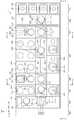
도 2는 본 발명의 실시예에 따른 기판 처리 설비를 보여주는 평면도이고, 도 3은 도 2의 설비를 A-A 방향에서 바라본 도면이며, 도 4는 도 2의 설비를 B-B 방향에서 바라본 도면이고, 도 5는 도 2의 설비를 C-C 방향에서 바라본 도면이다. 도 2 내지 도 5를을 참조하면, 기판 처리 설비(1)는 로드 포트(100), 인덱스 모듈(200), 제 1 버퍼 모듈(300), 도포 및 현상 모듈(400), 제 2 버퍼 모듈(500), 노광 전후 처리 모듈(600), 그리고 인터페이스 모듈(700)을 포함한다. 로드 포트(100), 인덱스 모듈(200), 제 1 버퍼 모듈(300), 도포 및 현상 모듈(400), 제 2 버퍼 모듈(500), 노광 전후 처리 모듈(600), 그리고 인터페이스 모듈(700)은 순차적으로 일 방향으로 일렬로 배치된다.FIG. 2 is a plan view showing a substrate processing facility according to an embodiment of the present invention, FIG. 3 is a view of the facility of FIG. 2 viewed from the direction AA, FIG. 4 is a view of the facility of FIG. Is a view of the equipment of Fig. 2 viewed from the CC direction. 2 to 5, the
이하, 로드 포트(100), 인덱스 모듈(200), 제 1 버퍼 모듈(300), 도포 및 현상 모듈(400), 제 2 버퍼 모듈(500), 노광 전후 처리 모듈(600), 그리고 인터페이스 모듈(700)이 배치된 방향을 제 1 방향(12)이라 칭하고, 상부에서 바라볼 때 제 1 방향(12)과 수직한 방향을 제 2 방향(14)이라 칭하고, 제 1 방향(12) 및 제 2 방향(14)과 각각 수직한 방향을 제 3 방향(16)이라 칭한다.Hereinafter, the
기판(W)은 카세트(20) 내에 수납된 상태로 이동된다. 이때 카세트(20)는 외부로부터 밀폐될 수 있는 구조를 가진다. 예컨대, 카세트(20)로는 전방에 도어를 가지는 전면 개방 일체식 포드(Front Open Unified Pod; FOUP)가 사용될 수 있다.The substrate W is moved in a state accommodated in the
이하에서는 로드 포트(100), 인덱스 모듈(200), 제 1 버퍼 모듈(300), 도포 및 현상 모듈(400), 제 2 버퍼 모듈(500), 노광 전후 처리 모듈(600), 그리고 인터페이스 모듈(700)에 대해 상세히 설명한다.Hereinafter, the
로드 포트(100)는 기판들(W)이 수납된 카세트(20)가 놓여지는 재치대(120)를 가진다. 재치대(120)는 복수개가 제공되며, 재치대들(200)은 제 2 방향(14)을 따라 일렬로 배치된다. 도 2에서는 4개의 재치대(120)가 제공되었다.The
인덱스 모듈(200)은 로드 포트(100)의 재치대(120)에 놓인 카세트(20)와 제 1 버퍼 모듈(300) 간에 기판(W)을 이송한다. 인덱스 모듈(200)은 프레임(210), 인덱스 로봇(220), 그리고 가이드 레일(230)을 가진다. 프레임(210)은 대체로 내부가 빈 직육면체의 형상으로 제공되며, 로드 포트(100)와 제 1 버퍼 모듈(300) 사이에 배치된다. 인덱스 모듈(200)의 프레임(210)은 후술하는 제 1 버퍼 모듈(300)의 프레임(310)보다 낮은 높이로 제공될 수 있다. 인덱스 로봇(220)과 가이드 레일(230)은 프레임(210) 내에 배치된다. 인덱스 로봇(220)은 기판(W)을 직접 핸들링하는 핸드(221)가 제 1 방향(12), 제 2 방향(14), 제 3 방향(16)으로 이동 가능하고 회전될 수 있도록 4축 구동이 가능한 구조를 가진다. 인덱스 로봇(220)은 핸드(221), 아암(222), 지지대(223), 그리고 받침대(224)를 가진다. 핸드(221)는 아암(222)에 고정 설치된다. 아암(222)은 신축 가능한 구조 및 회전 가능한 구조로 제공된다. 지지대(223)는 그 길이 방향이 제 3 방향(16)을 따라 배치된다. 아암(222)은 지지대(223)를 따라 이동 가능하도록 지지대(223)에 결합된다. 지지대(223)는 받침대(224)에 고정결합된다. 가이드 레일(230)은 그 길이 방향이 제 2 방향(14)을 따라 배치되도록 제공된다. 받침대(224)는 가이드 레일(230)을 따라 직선 이동 가능하도록 가이드 레일(230)에 결합된다. 또한, 도시되지는 않았지만, 프레임(210)에는 카세트(20)의 도어를 개폐하는 도어 오프너가 더 제공된다.The
제 1 버퍼 모듈(300)은 프레임(310), 제 1 버퍼(320), 제 2 버퍼(330), 냉각 챔버(350), 그리고 제 1 버퍼 로봇(360)을 가진다. 프레임(310)은 내부가 빈 직육면체의 형상으로 제공되며, 인덱스 모듈(200)과 도포 및 현상 모듈(400) 사이에 배치된다. 제 1 버퍼(320), 제 2 버퍼(330), 냉각 챔버(350), 그리고 제 1 버퍼 로봇(360)은 프레임(310) 내에 위치된다. 냉각 챔버(350), 제 2 버퍼(330), 그리고 제 1 버퍼(320)는 순차적으로 아래에서부터 제 3 방향(16)을 따라 배치된다. 제 1 버퍼(320)는 후술하는 도포 및 현상 모듈(400)의 도포 모듈(401)과 대응되는 높이에 위치되고, 제 2 버퍼(330)와 냉각 챔버(350)는 후술하는 도포 및 현상 모듈(400)의 현상 모듈(402)과 대응되는 높이에 위치된다. 제 1 버퍼 로봇(360)은 제 2 버퍼(330), 냉각 챔버(350), 그리고 제 1 버퍼(320)와 제 2 방향(14)으로 일정 거리 이격되게 위치된다.The
제 1 버퍼(320)와 제 2 버퍼(330)는 각각 복수의 기판들(W)을 일시적으로 보관한다. 제 2 버퍼(330)는 하우징(331)과 복수의 지지대들(332)을 가진다. 지지대들(332)은 하우징(331) 내에 배치되며, 서로 간에 제 3 방향(16)을 따라 이격되게 제공된다. 각각의 지지대(332)에는 하나의 기판(W)이 놓인다. 하우징(331)은 인덱스 로봇(220), 제 1 버퍼 로봇(360), 그리고 후술하는 현상 모듈(402)의 현상부 로봇(482)이 하우징(331) 내 지지대(332)에 기판(W)을 반입 또는 반출할 수 있도록 인덱스 로봇(220)이 제공된 방향, 제 1 버퍼 로봇(360)이 제공된 방향, 그리고 현상부 로봇(482)이 제공된 방향에 개구(도시되지 않음)를 가진다. 제 1 버퍼(320)는 제 2 버퍼(330)와 대체로 유사한 구조를 가진다. 다만, 제 1 버퍼(320)의 하우징(321)에는 제 1 버퍼 로봇(360)이 제공된 방향 및 후술하는 도포 모듈(401)에 위치된 도포부 로봇(432)이 제공된 방향에 개구를 가진다. 제 1 버퍼(320)에 제공된 지지대(322)의 수와 제 2 버퍼(330)에 제공된 지지대(332)의 수는 동일하거나 상이할 수 있다. 일 예에 의하면, 제 2 버퍼(330)에 제공된 지지대(332)의 수는 제 1 버퍼(320)에 제공된 지지대(322)의 수보다 많을 수 있다.The
제 1 버퍼 로봇(360)은 제 1 버퍼(320)와 제 2 버퍼(330) 간에 기판(W)을 이송시킨다. 제 1 버퍼 로봇(360)은 핸드(361), 아암(362), 그리고 지지대(363)를 가진다. 핸드(361)는 아암(362)에 고정 설치된다. 아암(362)은 신축 가능한 구조로 제공되어, 핸드(361)가 제 2 방향(14)을 따라 이동 가능하도록 한다. 아암(362)은 지지대(363)를 따라 제 3 방향(16)으로 직선 이동 가능하도록 지지대(363)에 결합된다. 지지대(363)는 제 2 버퍼(330)에 대응되는 위치부터 제 1 버퍼(320)에 대응되는 위치까지 연장된 길이를 가진다. 지지대(363)는 이보다 위 또는 아래 방향으로 더 길게 제공될 수 있다. 제 1 버퍼 로봇(360)은 단순히 핸드(361)가 제 2 방향(14) 및 제 3 방향(16)을 따른 2축 구동만 되도록 제공될 수 있다.The
냉각 챔버(350)는 각각 기판(W)을 냉각한다. 냉각 챔버(350)는 하우징(351)과 냉각 플레이트(352)를 가진다. 냉각 플레이트(352)는 기판(W)이 놓이는 상면 및 기판(W)을 냉각하는 냉각 수단(353)을 가진다. 냉각 수단(353)으로는 냉각수에 의한 냉각이나 열전 소자를 이용한 냉각 등 다양한 방식이 사용될 수 있다. 또한, 냉각 챔버(350)에는 기판(W)을 냉각 플레이트(352) 상에 위치시키는 리프트 핀 어셈블리(도시되지 않음)가 제공될 수 있다. 하우징(351)은 인덱스 로봇(220) 및 후술하는 현상 모듈(402)에 제공된 현상부 로봇(482)이 냉각 플레이트(352)에 기판(W)을 반입 또는 반출할 수 있도록 인덱스 로봇(220)이 제공된 방향 및 현상부 로봇(482)이 제공된 방향에 개구(도시되지 않음)를 가진다. 또한, 냉각 챔버(350)에는 상술한 개구를 개폐하는 도어들(도시되지 않음)이 제공될 수 있다.The cooling
도포 및 현상 모듈(400)은 노광 공정 전에 기판(W) 상에 포토 레지스트를 도포하는 공정 및 노광 공정 후에 기판(W)을 현상하는 공정을 수행한다. 도포 및 현상 모듈(400)은 대체로 직육면체의 형상을 가진다. 도포 및 현상 모듈(400)은 도포 모듈(401)과 현상 모듈(402)을 가진다. 도포 모듈(401)과 현상 모듈(402)은 서로 간에 층으로 구획되도록 배치된다. 일 예에 의하면, 도포 모듈(401)은 현상 모듈(402)의 상부에 위치된다.The application and
도포 모듈(401)은 기판(W)에 대해 포토 레지스트와 같은 감광액을 도포하는 공정 및 레지스트 도포 공정 전후에 기판(W)에 대해 가열 및 냉각과 같은 열처리 공정을 포함한다. 도포 모듈(401)은 레지스트 도포 유닛(410), 베이크 유닛(420), 그리고 반송 챔버(430)를 가진다. 레지스트 도포 유닛(410), 베이크 유닛(420), 그리고 반송 챔버(430)는 제 2 방향(14)을 따라 순차적으로 배치된다. 따라서 레지스트 도포 유닛(410)과 베이크 유닛(420)는 반송 챔버(430)를 사이에 두고 제 2 방향(14)으로 서로 이격되게 위치된다. 레지스트 도포 유닛(410)은 복수 개가 제공되며, 제 1 방향(12) 및 제 3 방향(16)으로 각각 복수 개씩 제공된다. 도면에서는 6개의 레지스트 도포 유닛(410)이 제공된 예가 도시되었다. 베이크 유닛(420)는 제 1 방향(12) 및 제 3 방향(16)으로 각각 복수 개씩 제공된다. 도면에서는 6개의 베이크 유닛(420)가 제공된 예가 도시되었다. 그러나 이와 달리 베이크 유닛(420)는 더 많거나 더 적은 수로 제공될 수 있다.The
반송 챔버(430)는 제 1 버퍼 모듈(300)의 제 1 버퍼(320)와 제 1 방향(12)으로 나란하게 위치된다. 반송 챔버(430) 내에는 도포부 로봇(432)과 가이드 레일(433)이 위치된다. 반송 챔버(430)는 대체로 직사각의 형상을 가진다. 도포부 로봇(432)은 베이크 유닛들(420), 레지스트 도포 유닛들(400), 제 1 버퍼 모듈(300)의 제 1 버퍼(320), 그리고 후술하는 제 2 버퍼 모듈(500)의 제 1 냉각 챔버(520) 간에 기판(W)을 이송한다. 가이드 레일(433)은 그 길이 방향이 제 1 방향(12)과 나란하도록 배치된다. 가이드 레일(433)은 도포부 로봇(432)이 제 1 방향(12)으로 직선 이동되도록 안내한다. 도포부 로봇(432)은 핸드(434), 아암(435), 지지대(436), 그리고 받침대(437)를 가진다. 핸드(434)는 아암(435)에 고정 설치된다. 아암(435)은 신축 가능한 구조로 제공되어 핸드(434)가 수평 방향으로 이동 가능하도록 한다. 지지대(436)는 그 길이 방향이 제 3 방향(16)을 따라 배치되도록 제공된다. 아암(435)은 지지대(436)를 따라 제 3 방향(16)으로 직선 이동 가능하도록 지지대(436)에 결합된다. 지지대(436)는 받침대(437)에 고정 결합되고, 받침대(437)는 가이드 레일(433)을 따라 이동 가능하도록 가이드 레일(433)에 결합된다.The
레지스트 도포 유닛들(410)은 모두 동일한 구조를 가진다. 다만, 각각의 레지스트 도포 유닛(410)에서 사용되는 감광액의 종류는 서로 상이할 수 있다. 일 예로서 감광액으로는 화학 증폭형 레지스트(chemical amplification resist)가 사용될 수 있다. 레지스트 도포 유닛(410)은 기판(W) 상에 감광액을 도포한다. 레지스트 도포 유닛(410)은 하우징(411), 지지 플레이트(412), 그리고 노즐(413)을 가진다. 하우징(411)은 상부가 개방된 컵 형상을 가진다. 지지 플레이트(412)는 하우징(411) 내에 위치되며, 기판(W)을 지지한다. 지지 플레이트(412)는 회전 가능하게 제공된다. 노즐(413)은 지지 플레이트(412)에 놓인 기판(W) 상으로 감광액을 공급한다. 노즐(413)은 원형의 관 형상을 가지고, 기판(W)의 중심으로 감광액을 공급할 수 있다. 선택적으로 노즐(413)은 기판(W)의 직경에 상응하는 길이를 가지고, 노즐(413)의 토출구는 슬릿으로 제공될 수 있다. 또한, 추가적으로 레지스트 도포 유닛(410)에는 감광액이 도포된 기판(W) 표면을 세정하기 위해 탈이온수와 같은 세정액을 공급하는 노즐(414)이 더 제공될 수 있다.The resist
베이크 유닛(800)은 기판(W)을 열처리한다. 베이크 유닛(800)는 감광액을 도포하기 전후 각각에 기판(W)을 열 처리한다. 베이크 유닛(800)은 감광액을 도포하기 전의 기판(W)의 표면 성질이 변화시키도록 기판(W)을 소정의 온도로 가열하고, 그 기판(W) 상에 점착제와 같은 처리액막을 형성할 수 있다. 베이크 유닛(800)은 감광액이 도포된 기판(W)을 감압 분위기에서 감광액막을 열 처리할 수 있다. 감광액막에 포함된 휘발성 물질을 휘발시킬 수 있다. 본 실시예에는 베이크 유닛(800)이 감광액막을 열 처리하는 유닛으로 설명한다.The
베이크 유닛(800)은 냉각 플레이트(820) 및 가열 유닛(1000)을 포함한다. 냉각 플레이트(820)는 가열 유닛(1000)에 의해 가열 처리된 기판(W)을 냉각 처리한다. 냉각 플레이트(820)는 원형의 판 형상으로 제공된다. 냉각 플레이트(820)의 내부에는 냉각수 또는 열전 소자와 같은 냉각 수단이 제공된다. 예컨대, 냉각 플레이트(820)에 놓여진 기판(W)은 상온과 동일하거나 이와 인접한 온도로 냉각 처리될 수 있다.The
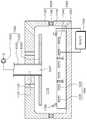
가열 유닛(1000)은 상압 또는 이보다 낮은 감압 분위기에서 기판(W)을 가열 처리한다. 가열 유닛(1000)은 기판(W)을 가열 처리하는 기판 처리 장치(1000)로 제공된다. 도 6은 도 2의 기판 처리 장치를 보여주는 단면도이다. 도 6을 참조하면, 기판 처리 장치(1000)는 챔버(1100), 기판 지지 유닛(1200), 배기 유닛(1500), 그리고 제어기(1900) 포함한다.The
챔버(1100)는 내부에 기판(W)을 가열 처리하는 처리 공간(1110)을 제공한다. 처리 공간(1110)은 외부와 차단된 공간으로 제공된다. 챔버(1100)은 상부 바디(1120), 하부 바디(1140), 그리고 실링 부재(1160)를 포함한다.The chamber 1100 provides a
상부 바디(1120)는 하부가 개방된 통 형상으로 제공된다. 상부 바디(1120)의 상면에는 중심홀(1122) 및 주변홀(1124)이 형성된다. 중심홀(1122)은 상부 바디(1120)의 중심에 형성된다. 중심홀(1122)은 처리 공간(1110)의 분위기가 배기되는 배기홀(1122)로 기능한다. 주변홀(1124)은 복수 개로 제공되며, 상부 바디(1120)의 중심을 벗어난 위치에 형성된다. 주변홀들(1124)은 처리 공간(1110)에 외부의 기류가 유입되는 유입홀(1124)로 기능한다. 주변홀들(1124)은 중심홀(1122)을 감싸도록 위치된다. 주변홀들(1124)은 원주 방향을 따라 서로 이격되게 위치된다. 일 예에 의하면, 주변홀(1124)은 4 개일 수 있다. 외부의 기류는 에어일 수 있다.The
선택적으로, 주변홀들(1124)은 3 개 또는 5 개 이상으로 제공될 수 있다. 또한 외부의 기류는 비활성 가스일 수 있다.Alternatively, the
하부 바디(1140)는 상부가 개방된 통 형상으로 제공된다. 하부 바디(1140)는 상부 바디(1120)의 아래에 위치된다. 상부 바디(1120) 및 하부 바디(1140)는 상하 방향으로 서로 마주보도록 위치된다. 상부 바디(1120) 및 하부 바디(1140)는 서로 조합되어 내부에 처리 공간(1110)을 형성한다. 상부 바디(1120) 및 하부 바디(1140)는 상하 방향에 대해 서로의 중심축이 일치되게 위치된다. 하부 바디(1140)는 상부 바디(1120)와 동일한 직경을 가질 수 있다. 즉, 하부 바디(1140)의 상단은 상부 바디(1120)의 하단과 대향되게 위치될 수 있다.The
상부 바디(1120) 및 하부 바디(1140) 중 하나는 승강 부재(1130)에 의해 개방 위치와 차단 위치로 이동되고, 다른 하나는 그 위치가 고정된다. 본 실시예에는 하부 바디(1140)의 위치가 고정되고, 상부 바디(1120)는 승강 부재(1130)에 의해 개방 위치 및 차단 위치 간에 이동되는 것으로 설명한다. 여기서 개방 위치는 상부 바디(1120)와 하부 바디(1140)가 서로 이격되어 처리 공간(1110)이 개방되는 위치이다. 차단 위치는 하부 바디(1140) 및 상부 바디(1120)에 의해 처리 공간(1110)이 외부로부터 밀폐되는 위치이다.One of the
실링 부재(1160)는 상부 바디(1120)와 하부 바디(1140) 사이에 위치된다. 실링 부재(1160)는 상부 바디(1120)와 하부 바디(1140) 간에 틈을 실링한다. 실링 부재(1160)는 환형의 링 형상을 가지는 오링 부재(1160)일 수 있다. 실링 부재(1160)는 하부 바디(1140)의 상단에 고정 결합될 수 있다.A sealing member 1160 is positioned between the
기판 지지 유닛(1300)은 처리 공간(1110)에서 기판(W)을 지지한다. 기판 지지 유닛(1300)은 하부 바디(1140)에 고정 결합된다. 기판 지지 유닛(1300)은 지지 플레이트(1320), 리프트 핀(1340), 돌기(1700), 제1가열 부재(1600), 그리고 제2가열 부재(1720)를 포함한다. 도 7은 도 6의 지지 플레이트를 보여주는 평면도이다. 도 6 및 도 7을 참조하면, 지지 플레이트(1320)는 제1가열 부재(1600)로부터 발생된 열을 기판(W)으로 전달한다. 지지 플레이트(1320)는 원형의 판 형상으로 제공된다. 지지 플레이트(1320)의 상면에는 지지면면이 제공된다. 지지면은 기판을 지지하는 영역으로 기능한다. 지지면은 지지 플레이트(1320)의 상면의 중앙 영역을 포함한다. 지지면에는 복수의 흡착홀들(미도시) 및 복수의 지지핀들(미도시)이 형성될 수 있다. 흡착홀들에는 진공이 제공되어 기판을 진공 흡착할 수 있다. 지지핀들은 기판과 지지면면을 소정 간격으로 이격시킨다. 지지핀들은 지지면으로부터 위로 돌출되게 제공된다. 지지핀들의 상단은 라운드지도록 제공된다. 기판은 지지핀들의 상단에 놓여진다. 이에 따라 지지핀과 기판 간에 접촉 면적을 최소화시키며, 기판의 전체 영역에 대한 열 전달을 균일하게 할 수 있다.The
지지 플레이트(1320)의 상면은 기판(W)보다 큰 직경을 가진다. 지지 플레이트(1320)의 상면에는 복수의 핀 홀들(1322)이 형성된다. 핀 홀들(1322)은 서로 상이한 영역에 위치된다. 상부에서 바라볼 때 핀 홀들(1322)은 지지 플레이트(1320)의 상면의 중심을 감싸도록 배열된다. 각각의 핀 홀(1322)은 원주 방향을 따라 서로 이격되게 배열된다. 핀 홀들(1322)은 서로 간에 동일 간격으로 이격되게 위치된다. 각각의 핀 홀(1322)에는 리프트 핀(1340)이 제공된다. 리프트 핀(1340)은 상단이 핀 홀(1322)로부터 돌출되거나 삽입되도록 상하 이동이 가능하다. 일 예에 의하면, 리프트 핀(1340)은 승강 위치 또는 하강 위치로 이동될 수 있다. 승강 위치는 리프트 핀(1340)의 상단이 핀 홀(1322)로부터 돌출되는 위치이고, 하강 위치는 리프트 핀(1340)이 핀 홀(1322) 내에 삽입되는 위치일 수 있다. 핀 홀들(1322)은 3 개로 제공될 수 있다. 지지 플레이트(1320)는 질화 알루미늄(AlN)을 포함하는 재질로 제공될 수 있다.The upper surface of the
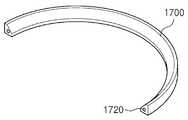
도 8은 도 6의 돌기를 보여주는 평면도이고, 도 9는 도 8의 돌기 및 제2가열 부재를 보여주는 절단 사시도이다. 도 8 및 도 9를 참조하면, 돌기(1700)는 지지 플레이트(1320)의 상면에 제공된다. 돌기(1700)는 환형의 링 형상을 가지도록 제공된다. 상부에서 바라볼 때 돌기(1700)는 지지면을 감싸는 직경을 가지도록 제공된다. 돌기(1700)의 상단은 지지면에 놓인 기판(W)보다 높게 제공된다. 일 예에 의하면, 돌기(1700)는 기판(W)의 위치를 정 위치로 안내하는 가이드일 수 있다. 돌기(1700)의 내측면은 위에서 아래로 갈수록 중심축에 가까워지는 방향을 따라 하향 경사지게 제공될 수 있다. 또한 돌기(1700)는 기판(W)과 지지면 사이에 형성된 가열 분위기가 기판(W)의 외측으로 유출되는 것을 방지할 수 있다.FIG. 8 is a plan view showing the projection of FIG. 6, and FIG. 9 is a cutaway perspective view showing the projection and the second heating member of FIG. 8 and 9, the
제1가열 부재(1600)는 지지면에 놓인 기판(W)을 제1온도로 가열 처리한다. 기판(W)은 제1가열 부재(1600)에 의해 제1영역이 가열 처리된다. 제1가열 부재(1600)는 지지면에 놓인 기판(W)보다 아래에 위치된다. 제1가열 부재(1600)은 지지 플레이트(1320) 내에 위치된다. 제1가열 부재는 제1히터(1620) 및 제2히터(1640)를 포함한다. 상부에서 바라볼 때 제1히터(1620)는 지지면의 중앙 영역에 중첩되게 위치되고, 제2히터(1640)는 지지면의 가장자리 영역에 중첩되게 위치된다. 제1히터(1620) 및 제2히터(1640) 각각은 동일 평면 상에 위치된다. 예컨대, 제1히터(1620) 및 제2히터(1640) 각각은 열선일 수 있다. 상부에서 바라볼 때 제1히터(1620) 및 제2히터(1640) 각각은 나선 형상을 가질 수 있다. 제1영역은 기판(W)의 저면일 수 있다.The
제2가열 부재(1720)는 지지면에 놓인 기판(W)을 제2온도로 가열 처리한다. 기판(W)은 제2가열 부재(1720)에 의해 제2영역이 가열 처리된다. 제2가열 부재(1720)는 제1가열 부재(1600)로부터 분리되게 제공되며, 제1가열 부재(1600)로부터 독립적으로 제어 가능하다. 제2가열 부재(1720)는 환형의 링 형상을 가지며, 돌기(1700) 내에 위치된다. 예컨대, 제2영역은 기판(W)의 측부일 수 있다. 일 예에 의하면, 제2온도는 제1온도와 동일하거나 이보다 낮은 온도일 수 있다.The
다시 도 6을 참조하면, 배기 유닛(1500)은 처리 공간(1110)에 유입된 기류의 흐름을 안내한다. 또한 배기 유닛(1500)은 처리 공간(1110)의 분위기를 배기한다. 배기 유닛(1500)은 배기관(1530) 및 안내판(1540)을 포함한다. 배기관(1530)는 길이 방향이 수직한 상하 방향을 향하는 관 형상을 가진다. 배기관(1530)는 상부 바디(1120)의 상벽을 관통하도록 위치된다. 일 예에 의하면, 배기관(1530)는 중심홀(1122)에 삽입되게 위치될 수 있다. 즉, 배기관(1530)의 하단은 처리 공간(1110) 내에 위치되고, 배기관(1530)의 상단은 처리 공간(1110)의 외부에 위치된다. 배기관(1530)의 상단에는 감압 부재(1560)가 연결된다. 감압 부재(1560)는 배기관(1530)를 감압한다. 이에 따라 처리 공간(1110)의 분위기는 통공(1542) 및 배기관(1530)를 순차적으러 거쳐 배기된다.Referring again to FIG. 6, the
안내판(1540)는 중심에 통공(1542)을 가지는 판 형상을 가진다. 안내판(1540)는 배기관(1530)의 하단으로부터 연장된 원형의 판 형상을 가진다. 안내판(1540)는 통공(1542)과 배기관(1530)의 내부가 서로 통하도록 배기관(1530)에 고정 결합된다. 안내판(1540)는 지지 플레이트(1320)의 상부에서 지지 플레이트(1320)의 지지면과 마주하게 위치된다. 안내판(1540)는 하부 바디(1140)보다 높게 위치된다. 일 예에 의하면, 안내판(1540)는 상부 바디(1120)와 마주하는 높이에 위치될 수 있다. 상부에서 바라볼 때 안내판(1540)는 주변홀(1124)과 중첩되게 위치되고, 상부 바디(1120)의 내측면과 이격되는 직경을 가진다. 이에 따라 안내판(1540)의 측단과 상부 바디(1120)의 내측면 간에는 틈이 발생되며, 이 틈은 주변홀(1124)을 통해 유입된 기류가 기판(W)으로 공급되는 흐름 경로로 제공된다.The
제어기(1900)는 제1가열 부재(1600) 및 제2가열 부재(1720)를 제어한다. 제어기(1900)는 제2온도가 제1온도보다 낮거나 동일하도록 각 가열 부재(1600,1720)를 제어한다. 일 예에 의하면, 제어기(1900)는 제1온도가 고정값을 가지도록 제1가열 부재(1600)를 제어하고, 제2온도가 가변 가능한 조절값을 가지도록 제2가열 부재(1720)를 제어할 수 있다. 또한 제어기(1900)는 기판(W)의 휨 정도를 근거로 제2온도를 조절한다. 일 예에 의하면, 기판(W)은 중앙 영역이 아래로 볼록한 휨 정도를 가지며, 제2온도를 휨 정도에 비례되게 조절할 수 있다. 제어기(1900)는 휨 정도가 클수록 제2온도를 높이고, 휨 정도가 적을수록 제2온도를 낮출 수 있다. 이러한 휨 정도 측정은 기판(W)이 처리 공간(1110에 반입되기 전에 측정되거나, 반입되는 중에 센서(미도시)에 의해 측정될 수 있다.The
다음은 상술한 기판 처리 장치를 이용하여 기판(W)을 열 처리하는 방법에 대해 설명한다. 챔버(1100)는 개방 위치로 이동되고, 도포부 로봇(432)에 지지된 기판(W)은 처리 공간(1110)으로 반입된다. 기판(W)은 반입되는 중에 센서(미도시)에 의해 휨 정도가 측정될 수 있다. 리프트 핀(1340)은 승강 위치로 이동되어 도포부 로봇(432)으로부터 기판(W)을 인수받는다. 리프트 핀(1340)에 기판(W)이 놓이면, 리프트 핀(1340)은 하강 위치로 이동되고, 기판(W)은 지지핀에 놓인다. 제2가열 부재(1720)는 휨 정도에 따라 제2온도가 조절된다. 도 10은 휨 정도가 다른 제1기판과 제2기판에 대한 제2온도를 보여주는 그래프이다. 도 10을 참조하면, 제1기판(W1)은 제2기판(W2)에 비해 그 휨 정도가 크다. 즉 제1기판(W1)은 제2기판(W2)의 비해 가장자리 영역의 상단 높이가 높다. 이에 따라 제1기판(W1)에 대한 제2온도(T1)는 제2기판(W2)에 대한 제2온도(T2)보다 높게 제공될 수 있다.Next, a method of heat-treating the substrate W using the above-described substrate processing apparatus will be described. The chamber 1100 is moved to the open position and the substrate W supported by the
상술한 실시예에 의하면, 기판(W)은 휨 정도를 가지며, 이는 지지면에 대한 기판(W)의 영역 별 밀착도가 상이하다. 이에 따라 기판(W)의 영역 별 온도는 상이하게 진행될 수 있다. 본 실시예에는 제2가열 부재(1720)가 기판(W)의 측부를 가열함에 따라 제1가열 부재(1600)에 대한 기판(W)의 측부를 열 보상할 수 있으며, 제2온도는 제1온도에 대한 열 보상 온도이므로, 제2온도는 제1온도에 비해 낮다.According to the above-described embodiment, the substrate W has a degree of warpage, which differs depending on the area of the substrate W relative to the support surface. Accordingly, the temperature of each region of the substrate W can be differently advanced. In this embodiment, the
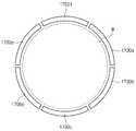
상술한 실시예에는 돌기(1700)가 단일 개로 제공되며, 환형의 링 형상을 가지는 것으로 설명하였다. 그러나 도 11과 같이, 돌기(1700a 내지 1700f)는 복수 개로 제공되며, 각각은 호 형상으로 제공될 수 있다. 돌기들(1700a 내지 1700f)은 서로 조합되어 환형의 링 형상을 가지도록 배열될 수 있다. 돌기들(1700a 내지 1700f) 각각의 내에는 제2가열 부재(1720)가 제공될 수 있다.In the above-described embodiment, the
또한 도 12와 같이, 제2가열 부재(1720)는 제1가열 부재(1600)로부터 연장되게 제공될 수 있다. 제2가열 부재(1720)는 제1가열 부재(1600)로부터 연장되는 열선일 수 있다. 제2가열 부재(1720)는 제2히터로부터 연장될 수 있다. 이에 따라 제1가열 부재(1600)와 제2가열 부재(1720)를 동시에 제어할 수 있다.Also, as shown in FIG. 12, the
또한 상술한 실시예와 달리, 제1가열 부재들(1600)은 지지 플레이트(1320)의 저면에 위치될 수 있다. 제1가열 부재들(1600)은 지지면의 서로 상이한 영역을 가열한다. 상부에서 바라볼 때 각 제1가열 부재(1600)에 대응되는 지지 플레이트(1320)의 영역은 히팅존들로 제공될 수 있다. 각각의 제1가열 부재(1600)는 온도가 독립 조절 가능하다. 예컨대, 히팅존은 15 개일 수 있다. 각 히팅존은 측정 부재(미도시)에 의해 온도가 측정된다. 제1가열 부재(1600)는 프린팅에 의한 패턴일 수 있다.Also, unlike the above-described embodiment, the
다시 도 2 내지 도 5를 참조하면, 현상 모듈(402)은 기판(W) 상에 패턴을 얻기 위해 현상액을 공급하여 포토 레지스트의 일부를 제거하는 현상 공정, 및 현상 공정 전후에 기판(W)에 대해 수행되는 가열 및 냉각과 같은 열처리 공정을 포함한다. 현상모듈(402)은 현상 유닛(460), 베이크 유닛(470), 그리고 반송 챔버(480)를 가진다. 현상 유닛(460), 베이크 유닛(470), 그리고 반송 챔버(480)는 제 2 방향(14)을 따라 순차적으로 배치된다. 따라서 현상 유닛(460)과 베이크 유닛(470)은 반송 챔버(480)를 사이에 두고 제 2 방향(14)으로 서로 이격되게 위치된다. 현상 유닛(460)은 복수 개가 제공되며, 제 1 방향(12) 및 제 3 방향(16)으로 각각 복수 개씩 제공된다. 도면에서는 6개의 현상 유닛(460)이 제공된 예가 도시되었다. 베이크 유닛(470)은 제 1 방향(12) 및 제 3 방향(16)으로 각각 복수 개씩 제공된다. 도면에서는 6개의 베이크 유닛(470)이 제공된 예가 도시되었다. 그러나 이와 달리 베이크 유닛(470)은 더 많은 수로 제공될 수 있다.2 to 5, the developing
반송 챔버(480)는 제 1 버퍼 모듈(300)의 제 2 버퍼(330)와 제 1 방향(12)으로 나란하게 위치된다. 반송 챔버(480) 내에는 현상부 로봇(482)과 가이드 레일(483)이 위치된다. 반송 챔버(480)는 대체로 직사각의 형상을 가진다. 현상부 로봇(482)은 베이크 유닛들(470), 현상 유닛들(460), 제 1 버퍼 모듈(300)의 제 2 버퍼(330)와 냉각 챔버(350), 그리고 제 2 버퍼 모듈(500)의 제 2 냉각 챔버(540) 간에 기판(W)을 이송한다. 가이드 레일(483)은 그 길이 방향이 제 1 방향(12)과 나란하도록 배치된다. 가이드 레일(483)은 현상부 로봇(482)이 제 1 방향(12)으로 직선 이동되도록 안내한다. 현상부 로봇(482)은 핸드(484), 아암(485), 지지대(486), 그리고 받침대(487)를 가진다. 핸드(484)는 아암(485)에 고정 설치된다. 아암(485)은 신축 가능한 구조로 제공되어 핸드(484)가 수평 방향으로 이동 가능하도록 한다. 지지대(486)는 그 길이 방향이 제 3 방향(16)을 따라 배치되도록 제공된다. 아암(485)은 지지대(486)를 따라 제 3 방향(16)으로 직선 이동 가능하도록 지지대(486)에 결합된다. 지지대(486)는 받침대(487)에 고정 결합된다. 받침대(487)는 가이드 레일(483)을 따라 이동 가능하도록 가이드 레일(483)에 결합된다.The
현상 유닛들(460)은 모두 동일한 구조를 가진다. 다만, 각각의 현상 유닛(460)에서 사용되는 현상액의 종류는 서로 상이할 수 있다. 현상 유닛(460)은 기판(W) 상의 포토 레지스트 중 광이 조사된 영역을 제거한다. 이때, 보호막 중 광이 조사된 영역도 같이 제거된다. 선택적으로 사용되는 포토 레지스트의 종류에 따라 포토 레지스트 및 보호막의 영역들 중 광이 조사되지 않은 영역만이 제거될 수 있다.The developing
현상 유닛(460)은 하우징(461), 지지 플레이트(462), 그리고 노즐(463)을 가진다. 하우징(461)은 상부가 개방된 컵 형상을 가진다. 지지 플레이트(462)는 하우징(461) 내에 위치되며, 기판(W)을 지지한다. 지지 플레이트(462)는 회전 가능하게 제공된다. 노즐(463)은 지지 플레이트(462)에 놓인 기판(W) 상으로 현상액을 공급한다. 노즐(463)은 원형의 관 형상을 가지고, 기판(W)의 중심으로 현상액 공급할 수 있다. 선택적으로 노즐(463)은 기판(W)의 직경에 상응하는 길이를 가지고, 노즐(463)의 토출구는 슬릿으로 제공될 수 있다. 또한, 현상 유닛(460)에는 추가적으로 현상액이 공급된 기판(W) 표면을 세정하기 위해 탈이온수와 같은 세정액을 공급하는 노즐(464)이 더 제공될 수 있다.The developing
현상모듈(402)의 베이크 유닛(470)은 기판(W)을 열처리한다. 예컨대, 베이크 유닛들(470)은 현상 공정이 수행되기 전에 기판(W)을 가열하는 포스트 베이크 공정 및 현상 공정이 수행된 후에 기판(W)을 가열하는 하드 베이크 공정 및 각각의 베이크 공정 이후에 가열된 기판(W)을 냉각하는 냉각 공정 등을 수행한다. 베이크 유닛(470)은 냉각 플레이트(471) 또는 가열 유닛(472)을 가진다. 냉각 플레이트(471)에는 냉각수 또는 열전 소자와 같은 냉각 수단(473)이 제공된다. 또는 가열 유닛(472)에는 열선 또는 열전 소자와 같은 가열 수단(474)이 제공된다. 냉각 플레이트(471)와 가열 유닛(472)는 하나의 베이크 유닛(470) 내에 각각 제공될 수 있다. 선택적으로 베이크 유닛(470)들 중 일부는 냉각 플레이트(471)만을 구비하고, 다른 일부는 가열 유닛(472)만을 구비할 수 있다. 현상 모듈(402)의 베이크 유닛(470)은 도포 모듈(401)의 베이크 유닛(800)과 동일한 구성을 가지므로, 이에 대한 상세한 설명은 생략한다.The
제 2 버퍼 모듈(500)은 도포 및 현상 모듈(400)과 노광 전후 처리 모듈(600) 사이에 기판(W)이 운반되는 통로로서 제공된다. 또한, 제 2 버퍼 모듈(500)은 기판(W)에 대해 냉각 공정이나 에지 노광 공정 등과 같은 소정의 공정을 수행한다. 제 2 버퍼 모듈(500)은 프레임(510), 버퍼(520), 제 1 냉각 챔버(530), 제 2 냉각 챔버(540), 에지 노광 챔버(550), 그리고 제 2 버퍼 로봇(560)을 가진다. 프레임(510)은 직육면체의 형상을 가진다. 버퍼(520), 제 1 냉각 챔버(530), 제 2 냉각 챔버(540), 에지 노광 챔버(550), 그리고 제 2 버퍼 로봇(560)은 프레임(510) 내에 위치된다. 버퍼(520), 제 1 냉각 챔버(530), 그리고 에지 노광 챔버(550)는 도포 모듈(401)에 대응하는 높이에 배치된다. 제 2 냉각 챔버(540)는 현상 모듈(402)에 대응하는 높이에 배치된다. 버퍼(520), 제 1 냉각 챔버(530), 그리고 제 2 냉각 챔버(540)는 순차적으로 제 3 방향(16)을 따라 일렬로 배치된다. 상부에서 바라볼 때 버퍼(520)은 도포 모듈(401)의 반송 챔버(430)와 제 1 방향(12)을 따라 배치된다. 에지 노광 챔버(550)는 버퍼(520) 또는 제 1 냉각 챔버(530)와 제 2 방향(14)으로 일정 거리 이격되게 배치된다.The
제 2 버퍼 로봇(560)은 버퍼(520), 제 1 냉각 챔버(530), 그리고 에지 노광 챔버(550) 간에 기판(W)을 운반한다. 제 2 버퍼 로봇(560)은 에지 노광 챔버(550)와 버퍼(520) 사이에 위치된다. 제 2 버퍼 로봇(560)은 제 1 버퍼 로봇(360)과 유사한 구조로 제공될 수 있다. 제 1 냉각 챔버(530)와 에지 노광 챔버(550)는 도포 모듈(401)에서 공정이 수행된 기판들(W)에 대해 후속 공정을 수행한다. 제 1 냉각 챔버(530)는 도포 모듈(401)에서 공정이 수행된 기판(W)을 냉각한다. 제 1 냉각 챔버(530)는 제 1 버퍼 모듈(300)의 냉각 챔버(350)과 유사한 구조를 가진다. 에지 노광 챔버(550)는 제 1 냉각 챔버(530)에서 냉각 공정이 수행된 기판들(W)에 대해 그 가장자리를 노광한다. 버퍼(520)는 에지 노광 챔버(550)에서 공정이 수행된 기판(W)들이 후술하는 전처리 모듈(601)로 운반되기 전에 기판(W)을 일시적으로 보관한다. 제 2 냉각 챔버(540)는 후술하는 후처리 모듈(602)에서 공정이 수행된 기판들(W)이 현상 모듈(402)로 운반되기 전에 기판들(W)을 냉각한다. 제 2 버퍼 모듈(500)은 현상 모듈(402)와 대응되는 높이에 추가된 버퍼를 더 가질 수 있다. 이 경우, 후처리 모듈(602)에서 공정이 수행된 기판들(W)은 추가된 버퍼에 일시적으로 보관된 후 현상 모듈(402)로 운반될 수 있다.The
노광 전후 처리 모듈(600)은, 노광 장치(900)가 액침 노광 공정을 수행하는 경우, 액침 노광시에 기판(W)에 도포된 포토레지스트 막을 보호하는 보호막을 도포하는 공정을 처리할 수 있다. 또한, 노광 전후 처리 모듈(600)은 노광 이후에 기판(W)을 세정하는 공정을 수행할 수 있다. 또한, 화학증폭형 레지스트를 사용하여 도포 공정이 수행된 경우, 노광 전후 처리 모듈(600)은 노광 후 베이크 공정을 처리할 수 있다.The pre- and
노광 전후 처리 모듈(600)은 전처리 모듈(601)과 후처리 모듈(602)을 가진다. 전처리 모듈(601)은 노광 공정 수행 전에 기판(W)을 처리하는 공정을 수행하고, 후처리 모듈(602)은 노광 공정 이후에 기판(W)을 처리하는 공정을 수행한다. 전처리 모듈(601)과 후처리 모듈(602)은 서로 간에 층으로 구획되도록 배치된다. 일 예에 의하면, 전처리 모듈(601)은 후처리 모듈(602)의 상부에 위치된다. 전처리 모듈(601)은 도포 모듈(401)과 동일한 높이로 제공된다. 후처리 모듈(602)은 현상 모듈(402)과 동일한 높이로 제공된다. 전처리 모듈(601)은 보호막 도포 유닛(610), 베이크 유닛(620), 그리고 반송 챔버(630)를 가진다. 보호막 도포 유닛(610), 반송 챔버(630), 그리고 베이크 유닛(620)은 제 2 방향(14)을 따라 순차적으로 배치된다. 따라서 보호막 도포 유닛(610)과 베이크 유닛(620)은 반송 챔버(630)를 사이에 두고 제 2 방향(14)으로 서로 이격되게 위치된다. 보호막 도포 유닛(610)은 복수 개가 제공되며, 서로 층을 이루도록 제 3 방향(16)을 따라 배치된다. 선택적으로 보호막 도포 유닛(610)은 제 1 방향(12) 및 제 3 방향(16)으로 각각 복수 개씩 제공될 수 있다. 베이크 유닛(620)은 복수 개가 제공되며, 서로 층을 이루도록 제 3 방향(16)을 따라 배치된다. 선택적으로 베이크 유닛(620)은 제 1 방향(12) 및 제 3 방향(16)으로 각각 복수 개씩 제공될 수 있다.The
반송 챔버(630)는 제 2 버퍼 모듈(500)의 제 1 냉각 챔버(530)와 제 1 방향(12)으로 나란하게 위치된다. 반송 챔버(630) 내에는 전처리 로봇(632)이 위치된다. 반송 챔버(630)는 대체로 정사각 또는 직사각의 형상을 가진다. 전처리 로봇(632)은 보호막 도포 유닛들(610), 베이크 유닛들(620), 제 2 버퍼 모듈(500)의 버퍼(520), 그리고 후술하는 인터페이스 모듈(700)의 제 1 버퍼(720) 간에 기판(W)을 이송한다. 전처리 로봇(632)은 핸드(633), 아암(634), 그리고 지지대(635)를 가진다. 핸드(633)는 아암(634)에 고정 설치된다. 아암(634)은 신축 가능한 구조 및 회전 가능한 구조로 제공된다. 아암(634)은 지지대(635)를 따라 제 3 방향(16)으로 직선 이동 가능하도록 지지대(635)에 결합된다.The
보호막 도포 유닛(610)은 액침 노광 시에 레지스트 막을 보호하는 보호막을 기판(W) 상에 도포한다. 보호막 도포 유닛(610)은 하우징(611), 지지 플레이트(612), 그리고 노즐(613)을 가진다. 하우징(611)은 상부가 개방된 컵 형상을 가진다. 지지 플레이트(612)는 하우징(611) 내에 위치되며, 기판(W)을 지지한다. 지지 플레이트(612)는 회전 가능하게 제공된다. 노즐(613)은 지지 플레이트(612)에 놓인 기판(W) 상으로 보호막 형성을 위한 보호액을 공급한다. 노즐(613)은 원형의 관 형상을 가지고, 기판(W)의 중심으로 보호액을 공급할 수 있다. 선택적으로 노즐(613)은 기판(W)의 직경에 상응하는 길이를 가지고, 노즐(613)의 토출구는 슬릿으로 제공될 수 있다. 이 경우, 지지 플레이트(612)는 고정된 상태로 제공될 수 있다. 보호액은 발포성 재료를 포함한다. 보호액은 포토 레지스터 및 물과의 친화력이 낮은 재료가 사용될 수 있다. 예컨대, 보호액은 불소계의 용제를 포함할 수 있다. 보호막 도포 유닛(610)은 지지 플레이트(612)에 놓인 기판(W)을 회전시키면서 기판(W)의 중심 영역으로 보호액을 공급한다.The protective
베이크 유닛(620)은 보호막이 도포된 기판(W)을 열처리한다. 베이크 유닛(620)은 냉각 플레이트(621) 또는 가열 플레이트(622)를 가진다. 냉각 플레이트(621)에는 냉각수 또는 열전 소자와 같은 냉각 수단(623)이 제공된다. 또는 가열 플레이트(622)에는 열선 또는 열전 소자와 같은 가열 수단(624)이 제공된다. 가열 플레이트(622)와 냉각 플레이트(621)는 하나의 베이크 유닛(620) 내에 각각 제공될 수 있다. 선택적으로 베이크 유닛들(620) 중 일부는 가열 플레이트(622) 만을 구비하고, 다른 일부는 냉각 플레이트(621) 만을 구비할 수 있다.The
후처리 모듈(602)은 세정 챔버(660), 노광 후 베이크 유닛(670), 그리고 반송 챔버(680)를 가진다. 세정 챔버(660), 반송 챔버(680), 그리고 노광 후 베이크 유닛(670)은 제 2 방향(14)을 따라 순차적으로 배치된다. 따라서 세정 챔버(660)와 노광 후 베이크 유닛(670)은 반송 챔버(680)를 사이에 두고 제 2 방향(14)으로 서로 이격되게 위치된다. 세정 챔버(660)는 복수 개가 제공되며, 서로 층을 이루도록 제 3 방향(16)을 따라 배치될 수 있다. 선택적으로 세정 챔버(660)는 제 1 방향(12) 및 제 3 방향(16)으로 각각 복수 개씩 제공될 수 있다. 노광 후 베이크 유닛(670)은 복수 개가 제공되며, 서로 층을 이루도록 제 3 방향(16)을 따라 배치될 수 있다. 선택적으로 노광 후 베이크 유닛(670)은 제 1 방향(12) 및 제 3 방향(16)으로 각각 복수 개씩 제공될 수 있다.The
반송 챔버(680)는 상부에서 바라볼 때 제 2 버퍼 모듈(500)의 제 2 냉각 챔버(540)와 제 1 방향(12)으로 나란하게 위치된다. 반송 챔버(680)는 대체로 정사각 또는 직사각의 형상을 가진다. 반송 챔버(680) 내에는 후처리 로봇(682)이 위치된다. 후처리 로봇(682)은 세정 챔버들(660), 노광 후 베이크 유닛들(670), 제 2 버퍼 모듈(500)의 제 2 냉각 챔버(540), 그리고 후술하는 인터페이스 모듈(700)의 제 2 버퍼(730) 간에 기판(W)을 운반한다. 후처리 모듈(602)에 제공된 후처리 로봇(682)은 전처리 모듈(601)에 제공된 전처리 로봇(632)과 동일한 구조로 제공될 수 있다.The
세정 챔버(660)는 노광 공정 이후에 기판(W)을 세정한다. 세정 챔버(660)는 하우징(661), 지지 플레이트(662), 그리고 노즐(663)을 가진다. 하우징(661)는 상부가 개방된 컵 형상을 가진다. 지지 플레이트(662)는 하우징(661) 내에 위치되며, 기판(W)을 지지한다. 지지 플레이트(662)는 회전 가능하게 제공된다. 노즐(663)은 지지 플레이트(662)에 놓인 기판(W) 상으로 세정액을 공급한다. 세정액으로는 탈이온수와 같은 물이 사용될 수 있다. 세정 챔버(660)는 지지 플레이트(662)에 놓인 기판(W)을 회전시키면서 기판(W)의 중심 영역으로 세정액을 공급한다. 선택적으로 기판(W)이 회전되는 동안 노즐(663)은 기판(W)의 중심 영역에서 가장자리 영역까지 직선 이동 또는 회전 이동할 수 있다.The
노광 후 베이크 유닛(670)은 원자외선을 이용하여 노광 공정이 수행된 기판(W)을 가열한다. 노광 후 베이크 공정은 기판(W)을 가열하여 노광에 의해 포토 레지스트에 생성된 산(acid)을 증폭시켜 포토 레지스트의 성질 변화를 완성시킨다. 노광 후 베이크 유닛(670)은 가열 플레이트(672)를 가진다. 가열 플레이트(672)에는 열선 또는 열전 소자와 같은 가열 수단(674)이 제공된다. 노광 후 베이크 유닛(670)은 그 내부에 냉각 플레이트(671)를 더 구비할 수 있다. 냉각 플레이트(671)에는 냉각수 또는 열전 소자와 같은 냉각 수단(673)이 제공된다. 또한, 선택적으로 냉각 플레이트(671)만을 가진 베이크 유닛이 더 제공될 수 있다.The
상술한 바와 같이 노광 전후 처리 모듈(600)에서 전처리 모듈(601)과 후처리 모듈(602)은 서로 간에 완전히 분리되도록 제공된다. 또한, 전처리 모듈(601)의 반송 챔버(630)와 후처리 모듈(602)의 반송 챔버(680)는 동일한 크기로 제공되어, 상부에서 바라볼 때 서로 간에 완전히 중첩되도록 제공될 수 있다. 또한, 보호막 도포 유닛(610)과 세정 챔버(660)는 서로 동일한 크기로 제공되어 상부에서 바라볼 때 서로 간에 완전히 중첩되도록 제공될 수 있다. 또한, 베이크 유닛(620)와 노광 후 베이크 유닛(670)은 동일한 크기로 제공되어, 상부에서 바라볼 때 서로 간에 완전히 중첩되도록 제공될 수 있다.As described above, the
인터페이스 모듈(700)은 노광 전후 처리 모듈(600), 및 노광 장치(900) 간에 기판(W)을 이송한다. 인터페이스 모듈(700)은 프레임(710), 제 1 버퍼(720), 제 2 버퍼(730), 그리고 인터페이스 로봇(740)를 가진다. 제 1 버퍼(720), 제 2 버퍼(730), 그리고 인터페이스 로봇(740)은 프레임(710) 내에 위치된다. 제 1 버퍼(720)와 제 2 버퍼(730)는 서로 간에 일정거리 이격되며, 서로 적층되도록 배치된다. 제 1 버퍼(720)는 제 2 버퍼(730)보다 높게 배치된다. 제 1 버퍼(720)는 전처리 모듈(601)과 대응되는 높이에 위치되고, 제 2 버퍼(730)는 후처리 모듈(602)에 대응되는 높이에 배치된다. 상부에서 바라볼 때 제 1 버퍼(720)는 전처리 모듈(601)의 반송 챔버(630)와 제 1 방향(12)을 따라 일렬로 배치되고, 제 2 버퍼(730)는 후처리 모듈(602)의 반송 챔버(630)와 제 1 방향(12)을 따라 일렬로 배치되게 위치된다.The
인터페이스 로봇(740)은 제 1 버퍼(720) 및 제 2 버퍼(730)와 제 2 방향(14)으로 이격되게 위치된다. 인터페이스 로봇(740)은 제 1 버퍼(720), 제 2 버퍼(730), 그리고 노광 장치(900) 간에 기판(W)을 운반한다. 인터페이스 로봇(740)은 제 2 버퍼 로봇(560)과 대체로 유사한 구조를 가진다.The
제 1 버퍼(720)는 전처리 모듈(601)에서 공정이 수행된 기판(W)들이 노광 장치(900)로 이동되기 전에 이들을 일시적으로 보관한다. 그리고 제 2 버퍼(730)는 노광 장치(900)에서 공정이 완료된 기판(W)들이 후처리 모듈(602)로 이동되기 전에 이들을 일시적으로 보관한다. 제 1 버퍼(720)는 하우징(721)과 복수의 지지대들(722)을 가진다. 지지대들(722)은 하우징(721) 내에 배치되며, 서로 간에 제 3 방향(16)을 따라 이격되게 제공된다. 각각의 지지대(722)에는 하나의 기판(W)이 놓인다. 하우징(721)은 인터페이스 로봇(740) 및 전처리 로봇(632)이 하우징(721) 내로 지지대(722)에 기판(W)을 반입 또는 반출할 수 있도록 인터페이스 로봇(740)이 제공된 방향 및 전처리 로봇(632)이 제공된 방향에 개구(도시되지 않음)를 가진다. 제 2 버퍼(730)는 제 1 버퍼(720)와 대체로 유사한 구조를 가진다. 다만, 제 2 버퍼(730)의 하우징(4531)에는 인터페이스 로봇(740)이 제공된 방향 및 후처리 로봇(682)이 제공된 방향에 개구(도시되지 않음)를 가진다. 인터페이스 모듈에는 기판에 대해 소정의 공정을 수행하는 챔버의 제공 없이 상술한 바와 같이 버퍼들 및 로봇만 제공될 수 있다.The
1300: 기판 지지 유닛 1320: 지지 플레이트
1340: 리프트 핀 1600: 제1가열 부재
1700: 돌기 1720: 제2가열 부재1300: substrate support unit 1320: support plate
1340: lift pin 1600: first heating element
1700: projection 1720: second heating member
Claims (15)
Translated fromKorean상기 처리 공간에 위치되며, 상면에 기판이 지지되는 지지면을 가지는 지지 플레이트와;
상기 지지면에 놓인 기판을 감싸도록 상기 상면에 제공되는 돌기와;
상기 플레이트에 제공되어 상기 지지면에 놓인 기판의 저면을 가열하는 제1가열 부재와;
상기 돌기에 제공되어 상기 지지면에 놓인 기판의 측부를 가열하는 제2가열 부재를 포함하는 기판 처리 장치.A chamber having a processing space therein;
A support plate located in the processing space and having a support surface on which an upper surface is supported;
A protrusion provided on the upper surface so as to surround the substrate placed on the support surface;
A first heating member provided on the plate to heat the bottom surface of the substrate placed on the support surface;
And a second heating member provided on the projection to heat a side portion of the substrate placed on the support surface.
상기 제1가열 부재 및 상기 제2가열 부재는 서로 분리되게 제공되며, 서로 독립적으로 제어가 가능한 기판 처리 장치.The method according to claim 1,
Wherein the first heating member and the second heating member are provided separately from each other and can be controlled independently of each other.
상기 제2가열 부재는 상기 제1가열부재로부터 연장되게 제공되는 기판 처리 장치.The method according to claim 1,
And the second heating member is provided extending from the first heating member.
상기 돌기는 환형의 링 형상을 가지는 기판 처리 장치.The method according to claim 1,
Wherein the projection has an annular ring shape.
상기 제2가열 부재의 상단은 상기 지지면에 높인 기판의 상단보다 높은 기판 처리 장치.5. The method according to any one of claims 1 to 4,
And the upper end of the second heating member is higher than the upper end of the substrate that is raised on the support surface.
상기 장치는,
상기 제1가열 부재 및 상기 제2가열 부재를 제어하는 제어기를 더 포함하되,
상기 제어기는 상기 제1가열 부재를 제1온도로 조절하고, 상기 제2가열 부재를 제2온도로 조절하되,
상기 제1온도 및 상기 제2온도는 서로 상이한 기판 처리 장치.5. The method according to any one of claims 1 to 4,
The apparatus comprises:
Further comprising a controller for controlling the first heating member and the second heating member,
Wherein the controller adjusts the first heating member to a first temperature and the second heating member to a second temperature,
Wherein the first temperature and the second temperature are different from each other.
상기 제어기는 상기 제1온도가 상기 제2온도보다 높도록 상기 제2가열 부재를 제어하는 기판 처리 장치.The method according to claim 6,
Wherein the controller controls the second heating member such that the first temperature is higher than the second temperature.
상기 제1가열 부재는 상기 지지면에 놓인 상기 기판의 저면을 제1온도로 가열하고,
상기 제2가열 부재는 상기 지지면에 놓인 상기 기판의 측부를 제2온도로 가열하되,
상기 제1온도는 상기 제2온도와 상이한 기판 처리 방법.A method for heat-treating a substrate using the apparatus of claim 1,
The first heating member heats the bottom surface of the substrate placed on the supporting surface to a first temperature,
The second heating member heats the side of the substrate resting on the support surface to a second temperature,
Wherein the first temperature is different from the second temperature.
상기 제1온도는 상기 제2온도보다 높은 기판 처리 방법.9. The method of claim 8,
Wherein the first temperature is higher than the second temperature.
상기 제2온도는 상기 기판의 휨 정도에 따라 제어되는 기판 처리 방법.9. The method of claim 8,
Wherein the second temperature is controlled according to a degree of warp of the substrate.
상기 기판은 중앙 영역이 아래로 볼록한 휨 정도를 가지며,
상기 휨 정도가 클수록 상기 제2온도를 높이는 기판 처리 방법.11. The method of claim 10,
Wherein the substrate has a degree of warpage in which the central region is convex downward,
Wherein the second temperature is increased as the degree of warpage increases.
상면에 기판이 지지되는 지지면을 가지는 지지 플레이트와;
상기 지지면에 놓인 기판을 감싸도록 상기 상면에 제공되는 돌기와;
상기 플레이트에 제공되어 상기 지지면에 놓인 기판의 저면을 가열하는 제1가열 부재와;
상기 돌기에 제공되어 상기 지지면에 놓인 기판의 측부를 가열하는 제2가열 부재를 포함하는 기판 지지 유닛.An apparatus for supporting a substrate,
A support plate having a support surface on which an upper surface of the substrate is supported;
A protrusion provided on the upper surface so as to surround the substrate placed on the support surface;
A first heating member provided on the plate to heat the bottom surface of the substrate placed on the support surface;
And a second heating member provided on the projection to heat a side portion of the substrate placed on the support surface.
상기 제1가열 부재 및 상기 제2가열 부재는 서로 분리되게 제공되며, 서로 독립적으로 제어가 가능한 기판 지지 유닛.13. The method of claim 12,
Wherein the first heating member and the second heating member are provided separately from each other and can be controlled independently of each other.
상기 돌기는 환형의 링 형상을 가지는 기판 지지 유닛.14. The method of claim 13,
Wherein the projection has an annular ring shape.
상기 제1가열 부재를 기판의 저면을 제1온도로 가열하고, 상기 제2가열 부재는 기판의 측부를 제2온도로 가열하되,
상기 제2온도는 상기 제1온도보다 낮은 기판 지지 유닛.
15. The method according to any one of claims 12 to 14,
Wherein the first heating member heats the bottom surface of the substrate to a first temperature and the second heating member heats the side of the substrate to a second temperature,
Wherein the second temperature is less than the first temperature.
Priority Applications (1)
| Application Number | Priority Date | Filing Date | Title |
|---|---|---|---|
| KR1020170123097AKR102403200B1 (en) | 2017-09-25 | 2017-09-25 | Unit for supporting substrate, Apparatus for treating substrate, and Method for treating substrate |
Applications Claiming Priority (1)
| Application Number | Priority Date | Filing Date | Title |
|---|---|---|---|
| KR1020170123097AKR102403200B1 (en) | 2017-09-25 | 2017-09-25 | Unit for supporting substrate, Apparatus for treating substrate, and Method for treating substrate |
Publications (2)
| Publication Number | Publication Date |
|---|---|
| KR20190034725Atrue KR20190034725A (en) | 2019-04-03 |
| KR102403200B1 KR102403200B1 (en) | 2022-05-27 |
Family
ID=66164954
Family Applications (1)
| Application Number | Title | Priority Date | Filing Date |
|---|---|---|---|
| KR1020170123097AActiveKR102403200B1 (en) | 2017-09-25 | 2017-09-25 | Unit for supporting substrate, Apparatus for treating substrate, and Method for treating substrate |
Country Status (1)
| Country | Link |
|---|---|
| KR (1) | KR102403200B1 (en) |
Families Citing this family (1)
| Publication number | Priority date | Publication date | Assignee | Title |
|---|---|---|---|---|
| KR20240041406A (en) | 2022-09-22 | 2024-04-01 | 세메스 주식회사 | Thermal processing apparatus and operation method thereof |
Citations (5)
| Publication number | Priority date | Publication date | Assignee | Title |
|---|---|---|---|---|
| JP2006019565A (en)* | 2004-07-02 | 2006-01-19 | Dainippon Screen Mfg Co Ltd | Heat treatment apparatus |
| KR100793170B1 (en)* | 2006-08-30 | 2008-01-10 | 세메스 주식회사 | Bake Device and Method |
| KR20080069125A (en)* | 2007-01-22 | 2008-07-25 | 도쿄엘렉트론가부시키가이샤 | Heating device, heating method and storage medium |
| KR20100053138A (en) | 2008-11-12 | 2010-05-20 | 세메스 주식회사 | Connector protection apparatus, bake apparatus with it and method for protecting connector thereof |
| WO2017101738A1 (en)* | 2015-12-17 | 2017-06-22 | 北京北方微电子基地设备工艺研究中心有限责任公司 | Electrostatic chuck mechanism and semiconductor processing device |
- 2017
- 2017-09-25KRKR1020170123097Apatent/KR102403200B1/enactiveActive
Patent Citations (5)
| Publication number | Priority date | Publication date | Assignee | Title |
|---|---|---|---|---|
| JP2006019565A (en)* | 2004-07-02 | 2006-01-19 | Dainippon Screen Mfg Co Ltd | Heat treatment apparatus |
| KR100793170B1 (en)* | 2006-08-30 | 2008-01-10 | 세메스 주식회사 | Bake Device and Method |
| KR20080069125A (en)* | 2007-01-22 | 2008-07-25 | 도쿄엘렉트론가부시키가이샤 | Heating device, heating method and storage medium |
| KR20100053138A (en) | 2008-11-12 | 2010-05-20 | 세메스 주식회사 | Connector protection apparatus, bake apparatus with it and method for protecting connector thereof |
| WO2017101738A1 (en)* | 2015-12-17 | 2017-06-22 | 北京北方微电子基地设备工艺研究中心有限责任公司 | Electrostatic chuck mechanism and semiconductor processing device |
Also Published As
| Publication number | Publication date |
|---|---|
| KR102403200B1 (en) | 2022-05-27 |
Similar Documents
| Publication | Publication Date | Title |
|---|---|---|
| KR101958636B1 (en) | Apparatus for supporting substrate, System for treating substrate, and Method for treating substrate | |
| KR20180000928A (en) | unit for treating substrate and bake apparatus a having the unit and method processing substrate by using thereof | |
| KR102099116B1 (en) | Apparatus and Method for treating substrate | |
| KR102324408B1 (en) | Apparatus and method for treating substrate | |
| KR102188354B1 (en) | Apparatus and Method for treating substrate | |
| KR101935945B1 (en) | Apparatus for treating substrate | |
| KR102516725B1 (en) | bake apparatus a having the unit and method processing substrate by using thereof | |
| KR101870659B1 (en) | Apparatus and Method for treating substrate | |
| KR102315662B1 (en) | Substrate treating apparatus and method | |
| KR101914483B1 (en) | Apparatus for heating substrate | |
| KR20170006779A (en) | Apparatus for treating a substrate | |
| KR20190004494A (en) | Apparatus for treating substrate | |
| KR101909481B1 (en) | Bake unit, Apparatus and method for treating substrate with the unit | |
| KR101935940B1 (en) | Apparatus and Method for treating substrate | |
| KR101870655B1 (en) | Apparatus for treatinf substrate | |
| KR101909183B1 (en) | Apparatus for treating substrate | |
| KR20190042839A (en) | Apparatus and Method for treating substrate | |
| KR20180054948A (en) | Apparatus anf Method for treating substrate | |
| KR20170024211A (en) | Unit for supporting substrate, Apparatus for treating substrate, and Method for treating substrate | |
| KR102403200B1 (en) | Unit for supporting substrate, Apparatus for treating substrate, and Method for treating substrate | |
| KR102037915B1 (en) | Apparatus for treating substrate | |
| KR102444878B1 (en) | substrate processing equipment | |
| KR20170056224A (en) | Bake apparatus and bake method | |
| KR20170056990A (en) | Apparatus for treating substrate and Exhaust method | |
| KR101870651B1 (en) | Apparatus for treating substrate |
Legal Events
| Date | Code | Title | Description |
|---|---|---|---|
| PA0109 | Patent application | Patent event code:PA01091R01D Comment text:Patent Application Patent event date:20170925 | |
| PG1501 | Laying open of application | ||
| A201 | Request for examination | ||
| PA0201 | Request for examination | Patent event code:PA02012R01D Patent event date:20200805 Comment text:Request for Examination of Application Patent event code:PA02011R01I Patent event date:20170925 Comment text:Patent Application | |
| E902 | Notification of reason for refusal | ||
| PE0902 | Notice of grounds for rejection | Comment text:Notification of reason for refusal Patent event date:20211209 Patent event code:PE09021S01D | |
| E701 | Decision to grant or registration of patent right | ||
| PE0701 | Decision of registration | Patent event code:PE07011S01D Comment text:Decision to Grant Registration Patent event date:20220509 | |
| GRNT | Written decision to grant | ||
| PR0701 | Registration of establishment | Comment text:Registration of Establishment Patent event date:20220524 Patent event code:PR07011E01D | |
| PR1002 | Payment of registration fee | Payment date:20220525 End annual number:3 Start annual number:1 | |
| PG1601 | Publication of registration |