KR20190034354A - System, cartridge, beverage preparation unit and method for producing a beverage - Google Patents
System, cartridge, beverage preparation unit and method for producing a beverageDownload PDFInfo
- Publication number
- KR20190034354A KR20190034354AKR1020197008237AKR20197008237AKR20190034354AKR 20190034354 AKR20190034354 AKR 20190034354AKR 1020197008237 AKR1020197008237 AKR 1020197008237AKR 20197008237 AKR20197008237 AKR 20197008237AKR 20190034354 AKR20190034354 AKR 20190034354A
- Authority
- KR
- South Korea
- Prior art keywords
- cartridge
- beverage
- mixing chamber
- preparation unit
- beverage preparation
- Prior art date
- Legal status (The legal status is an assumption and is not a legal conclusion. Google has not performed a legal analysis and makes no representation as to the accuracy of the status listed.)
- Ceased
Links
- 235000013361beverageNutrition0.000titleclaimsabstractdescription370
- 238000002360preparation methodMethods0.000titleclaimsabstractdescription122
- 238000004519manufacturing processMethods0.000titleclaimsdescription40
- 238000002156mixingMethods0.000claimsabstractdescription151
- 239000000463materialSubstances0.000claimsabstractdescription112
- 238000003860storageMethods0.000claimsabstractdescription112
- 238000007789sealingMethods0.000claimsdescription92
- 239000007788liquidSubstances0.000claimsdescription87
- 230000008878couplingEffects0.000claimsdescription49
- 238000010168coupling processMethods0.000claimsdescription49
- 238000005859coupling reactionMethods0.000claimsdescription49
- 238000000034methodMethods0.000claimsdescription35
- 238000003780insertionMethods0.000claimsdescription28
- 230000037431insertionEffects0.000claimsdescription28
- 238000001816coolingMethods0.000claimsdescription19
- 239000000126substanceSubstances0.000claimsdescription17
- CURLTUGMZLYLDI-UHFFFAOYSA-NCarbon dioxideChemical compoundO=C=OCURLTUGMZLYLDI-UHFFFAOYSA-N0.000claimsdescription15
- 229910002092carbon dioxideInorganic materials0.000claimsdescription7
- 239000001569carbon dioxideSubstances0.000claimsdescription7
- 230000009471actionEffects0.000claimsdescription4
- 230000004913activationEffects0.000claimsdescription4
- 238000007664blowingMethods0.000claimsdescription4
- 239000012530fluidSubstances0.000abstractdescription4
- 239000012528membraneSubstances0.000description10
- XLYOFNOQVPJJNP-UHFFFAOYSA-NwaterSubstancesOXLYOFNOQVPJJNP-UHFFFAOYSA-N0.000description10
- 238000011109contaminationMethods0.000description9
- 238000012546transferMethods0.000description7
- 230000008901benefitEffects0.000description5
- BVKZGUZCCUSVTD-UHFFFAOYSA-Ncarbonic acidChemical compoundOC(O)=OBVKZGUZCCUSVTD-UHFFFAOYSA-N0.000description5
- 235000014214soft drinkNutrition0.000description5
- 230000001476alcoholic effectEffects0.000description4
- BVKZGUZCCUSVTD-UHFFFAOYSA-LCarbonateChemical compound[O-]C([O-])=OBVKZGUZCCUSVTD-UHFFFAOYSA-L0.000description3
- LFQSCWFLJHTTHZ-UHFFFAOYSA-NEthanolChemical compoundCCOLFQSCWFLJHTTHZ-UHFFFAOYSA-N0.000description3
- 239000006096absorbing agentSubstances0.000description3
- 239000011324beadSubstances0.000description3
- 238000004140cleaningMethods0.000description3
- 238000007599dischargingMethods0.000description3
- 235000013399edible fruitsNutrition0.000description3
- 235000015203fruit juiceNutrition0.000description3
- 235000019687LambNutrition0.000description2
- 244000269722Thea sinensisSpecies0.000description2
- RYYVLZVUVIJVGH-UHFFFAOYSA-NcaffeineChemical compoundCN1C(=O)N(C)C(=O)C2=C1N=CN2CRYYVLZVUVIJVGH-UHFFFAOYSA-N0.000description2
- 235000014171carbonated beverageNutrition0.000description2
- UHZZMRAGKVHANO-UHFFFAOYSA-Mchlormequat chlorideChemical compound[Cl-].C[N+](C)(C)CCClUHZZMRAGKVHANO-UHFFFAOYSA-M0.000description2
- 238000004891communicationMethods0.000description2
- 230000006835compressionEffects0.000description2
- 238000007906compressionMethods0.000description2
- 229920001971elastomerPolymers0.000description2
- 235000019441ethanolNutrition0.000description2
- 235000015122lemonadeNutrition0.000description2
- 239000000203mixtureSubstances0.000description2
- 229920000915polyvinyl chloridePolymers0.000description2
- 239000004800polyvinyl chlorideSubstances0.000description2
- 239000000843powderSubstances0.000description2
- 235000015040sparkling wineNutrition0.000description2
- 230000001360synchronised effectEffects0.000description2
- 235000013616teaNutrition0.000description2
- 235000015192vegetable juiceNutrition0.000description2
- 235000014101wineNutrition0.000description2
- 235000021559Fruit Juice ConcentrateNutrition0.000description1
- 244000043261Hevea brasiliensisSpecies0.000description1
- LPHGQDQBBGAPDZ-UHFFFAOYSA-NIsocaffeineNatural productsCN1C(=O)N(C)C(=O)C2=C1N(C)C=N2LPHGQDQBBGAPDZ-UHFFFAOYSA-N0.000description1
- 238000009825accumulationMethods0.000description1
- 239000002253acidSubstances0.000description1
- 230000003213activating effectEffects0.000description1
- 235000013334alcoholic beverageNutrition0.000description1
- 235000013405beerNutrition0.000description1
- 230000015572biosynthetic processEffects0.000description1
- 229960001948caffeineDrugs0.000description1
- VJEONQKOZGKCAK-UHFFFAOYSA-NcaffeineNatural productsCN1C(=O)N(C)C(=O)C2=C1C=CN2CVJEONQKOZGKCAK-UHFFFAOYSA-N0.000description1
- 125000005587carbonate groupChemical group0.000description1
- 235000012174carbonated soft drinkNutrition0.000description1
- 235000019219chocolateNutrition0.000description1
- 235000020965cold beverageNutrition0.000description1
- 238000013461designMethods0.000description1
- 238000006073displacement reactionMethods0.000description1
- 239000013013elastic materialSubstances0.000description1
- 239000000806elastomerSubstances0.000description1
- 239000000796flavoring agentSubstances0.000description1
- 235000019634flavorsNutrition0.000description1
- 238000011010flushing procedureMethods0.000description1
- 239000006260foamSubstances0.000description1
- 239000011888foilSubstances0.000description1
- 235000019990fruit wineNutrition0.000description1
- 235000011389fruit/vegetable juiceNutrition0.000description1
- 239000011521glassSubstances0.000description1
- 230000010354integrationEffects0.000description1
- 238000012423maintenanceMethods0.000description1
- 230000007246mechanismEffects0.000description1
- 235000013336milkNutrition0.000description1
- 239000008267milkSubstances0.000description1
- 210000004080milkAnatomy0.000description1
- 235000020124milk-based beverageNutrition0.000description1
- 229920003052natural elastomerPolymers0.000description1
- 229920001194natural rubberPolymers0.000description1
- 239000002245particleSubstances0.000description1
- 239000013618particulate matterSubstances0.000description1
- 239000004014plasticizerSubstances0.000description1
- 229920001084poly(chloroprene)Polymers0.000description1
- 229920002635polyurethanePolymers0.000description1
- 239000004814polyurethaneSubstances0.000description1
- 238000003825pressingMethods0.000description1
- 230000008569processEffects0.000description1
- 238000005057refrigerationMethods0.000description1
- 230000000717retained effectEffects0.000description1
- 230000002441reversible effectEffects0.000description1
- 239000007787solidSubstances0.000description1
Images


Classifications
- B—PERFORMING OPERATIONS; TRANSPORTING
- B67—OPENING, CLOSING OR CLEANING BOTTLES, JARS OR SIMILAR CONTAINERS; LIQUID HANDLING
- B67D—DISPENSING, DELIVERING OR TRANSFERRING LIQUIDS, NOT OTHERWISE PROVIDED FOR
- B67D1/00—Apparatus or devices for dispensing beverages on draught
- B67D1/08—Details
- B—PERFORMING OPERATIONS; TRANSPORTING
- B67—OPENING, CLOSING OR CLEANING BOTTLES, JARS OR SIMILAR CONTAINERS; LIQUID HANDLING
- B67D—DISPENSING, DELIVERING OR TRANSFERRING LIQUIDS, NOT OTHERWISE PROVIDED FOR
- B67D1/00—Apparatus or devices for dispensing beverages on draught
- B67D1/0042—Details of specific parts of the dispensers
- B67D1/0078—Ingredient cartridges
- A—HUMAN NECESSITIES
- A23—FOODS OR FOODSTUFFS; TREATMENT THEREOF, NOT COVERED BY OTHER CLASSES
- A23L—FOODS, FOODSTUFFS OR NON-ALCOHOLIC BEVERAGES, NOT OTHERWISE PROVIDED FOR; PREPARATION OR TREATMENT THEREOF
- A23L2/00—Non-alcoholic beverages; Dry compositions or concentrates therefor; Preparation or treatment thereof
- A23L2/385—Concentrates of non-alcoholic beverages
- A23L2/39—Dry compositions
- A—HUMAN NECESSITIES
- A23—FOODS OR FOODSTUFFS; TREATMENT THEREOF, NOT COVERED BY OTHER CLASSES
- A23L—FOODS, FOODSTUFFS OR NON-ALCOHOLIC BEVERAGES, NOT OTHERWISE PROVIDED FOR; PREPARATION OR TREATMENT THEREOF
- A23L2/00—Non-alcoholic beverages; Dry compositions or concentrates therefor; Preparation or treatment thereof
- A23L2/52—Adding ingredients
- A23L2/54—Mixing with gases
- A—HUMAN NECESSITIES
- A47—FURNITURE; DOMESTIC ARTICLES OR APPLIANCES; COFFEE MILLS; SPICE MILLS; SUCTION CLEANERS IN GENERAL
- A47J—KITCHEN EQUIPMENT; COFFEE MILLS; SPICE MILLS; APPARATUS FOR MAKING BEVERAGES
- A47J31/00—Apparatus for making beverages
- A47J31/06—Filters or strainers for coffee or tea makers ; Holders therefor
- A47J31/0657—Filters or strainers for coffee or tea makers ; Holders therefor for brewing coffee under pressure, e.g. for espresso machines
- A47J31/0668—Filters or strainers for coffee or tea makers ; Holders therefor for brewing coffee under pressure, e.g. for espresso machines specially adapted for cartridges
- A47J31/0673—Means to perforate the cartridge for creating the beverage outlet
- A—HUMAN NECESSITIES
- A47—FURNITURE; DOMESTIC ARTICLES OR APPLIANCES; COFFEE MILLS; SPICE MILLS; SUCTION CLEANERS IN GENERAL
- A47J—KITCHEN EQUIPMENT; COFFEE MILLS; SPICE MILLS; APPARATUS FOR MAKING BEVERAGES
- A47J31/00—Apparatus for making beverages
- A47J31/24—Coffee-making apparatus in which hot water is passed through the filter under pressure, i.e. in which the coffee grounds are extracted under pressure
- A47J31/34—Coffee-making apparatus in which hot water is passed through the filter under pressure, i.e. in which the coffee grounds are extracted under pressure with hot water under liquid pressure
- A47J31/36—Coffee-making apparatus in which hot water is passed through the filter under pressure, i.e. in which the coffee grounds are extracted under pressure with hot water under liquid pressure with mechanical pressure-producing means
- A47J31/3604—Coffee-making apparatus in which hot water is passed through the filter under pressure, i.e. in which the coffee grounds are extracted under pressure with hot water under liquid pressure with mechanical pressure-producing means with a mechanism arranged to move the brewing chamber between loading, infusing and ejecting stations
- A47J31/3623—Cartridges being employed
- A47J31/3628—Perforating means therefor
- A—HUMAN NECESSITIES
- A47—FURNITURE; DOMESTIC ARTICLES OR APPLIANCES; COFFEE MILLS; SPICE MILLS; SUCTION CLEANERS IN GENERAL
- A47J—KITCHEN EQUIPMENT; COFFEE MILLS; SPICE MILLS; APPARATUS FOR MAKING BEVERAGES
- A47J31/00—Apparatus for making beverages
- A47J31/40—Beverage-making apparatus with dispensing means for adding a measured quantity of ingredients, e.g. coffee, water, sugar, cocoa, milk, tea
- A47J31/407—Beverage-making apparatus with dispensing means for adding a measured quantity of ingredients, e.g. coffee, water, sugar, cocoa, milk, tea with ingredient-containing cartridges; Cartridge-perforating means
- A—HUMAN NECESSITIES
- A47—FURNITURE; DOMESTIC ARTICLES OR APPLIANCES; COFFEE MILLS; SPICE MILLS; SUCTION CLEANERS IN GENERAL
- A47J—KITCHEN EQUIPMENT; COFFEE MILLS; SPICE MILLS; APPARATUS FOR MAKING BEVERAGES
- A47J31/00—Apparatus for making beverages
- A47J31/44—Parts or details or accessories of beverage-making apparatus
- A47J31/4403—Constructional details
- A47J31/441—Warming devices or supports for beverage containers
- A47J31/4425—Supports for beverage containers when filled or while being filled
- A—HUMAN NECESSITIES
- A47—FURNITURE; DOMESTIC ARTICLES OR APPLIANCES; COFFEE MILLS; SPICE MILLS; SUCTION CLEANERS IN GENERAL
- A47J—KITCHEN EQUIPMENT; COFFEE MILLS; SPICE MILLS; APPARATUS FOR MAKING BEVERAGES
- A47J31/00—Apparatus for making beverages
- A47J31/44—Parts or details or accessories of beverage-making apparatus
- A47J31/4492—Means to read code provided on ingredient pod or cartridge
- B—PERFORMING OPERATIONS; TRANSPORTING
- B65—CONVEYING; PACKING; STORING; HANDLING THIN OR FILAMENTARY MATERIAL
- B65D—CONTAINERS FOR STORAGE OR TRANSPORT OF ARTICLES OR MATERIALS, e.g. BAGS, BARRELS, BOTTLES, BOXES, CANS, CARTONS, CRATES, DRUMS, JARS, TANKS, HOPPERS, FORWARDING CONTAINERS; ACCESSORIES, CLOSURES, OR FITTINGS THEREFOR; PACKAGING ELEMENTS; PACKAGES
- B65D51/00—Closures not otherwise provided for
- B65D51/18—Arrangements of closures with protective outer cap-like covers or of two or more co-operating closures
- B65D51/20—Caps, lids, or covers co-operating with an inner closure arranged to be opened by piercing, cutting, or tearing
- B65D51/22—Caps, lids, or covers co-operating with an inner closure arranged to be opened by piercing, cutting, or tearing having means for piercing, cutting, or tearing the inner closure
- B65D51/221—Caps, lids, or covers co-operating with an inner closure arranged to be opened by piercing, cutting, or tearing having means for piercing, cutting, or tearing the inner closure a major part of the inner closure being left inside the container after the opening
- B65D51/222—Caps, lids, or covers co-operating with an inner closure arranged to be opened by piercing, cutting, or tearing having means for piercing, cutting, or tearing the inner closure a major part of the inner closure being left inside the container after the opening the piercing or cutting means being integral with, or fixedly attached to, the outer closure
- B65D51/223—Caps, lids, or covers co-operating with an inner closure arranged to be opened by piercing, cutting, or tearing having means for piercing, cutting, or tearing the inner closure a major part of the inner closure being left inside the container after the opening the piercing or cutting means being integral with, or fixedly attached to, the outer closure the outer closure having to be removed or inverted for piercing or cutting
- B—PERFORMING OPERATIONS; TRANSPORTING
- B65—CONVEYING; PACKING; STORING; HANDLING THIN OR FILAMENTARY MATERIAL
- B65D—CONTAINERS FOR STORAGE OR TRANSPORT OF ARTICLES OR MATERIALS, e.g. BAGS, BARRELS, BOTTLES, BOXES, CANS, CARTONS, CRATES, DRUMS, JARS, TANKS, HOPPERS, FORWARDING CONTAINERS; ACCESSORIES, CLOSURES, OR FITTINGS THEREFOR; PACKAGING ELEMENTS; PACKAGES
- B65D51/00—Closures not otherwise provided for
- B65D51/18—Arrangements of closures with protective outer cap-like covers or of two or more co-operating closures
- B65D51/20—Caps, lids, or covers co-operating with an inner closure arranged to be opened by piercing, cutting, or tearing
- B65D51/22—Caps, lids, or covers co-operating with an inner closure arranged to be opened by piercing, cutting, or tearing having means for piercing, cutting, or tearing the inner closure
- B65D51/221—Caps, lids, or covers co-operating with an inner closure arranged to be opened by piercing, cutting, or tearing having means for piercing, cutting, or tearing the inner closure a major part of the inner closure being left inside the container after the opening
- B65D51/226—Caps, lids, or covers co-operating with an inner closure arranged to be opened by piercing, cutting, or tearing having means for piercing, cutting, or tearing the inner closure a major part of the inner closure being left inside the container after the opening the piercing or cutting means being non integral with, or not fixedly attached to, the outer closure
- B—PERFORMING OPERATIONS; TRANSPORTING
- B65—CONVEYING; PACKING; STORING; HANDLING THIN OR FILAMENTARY MATERIAL
- B65D—CONTAINERS FOR STORAGE OR TRANSPORT OF ARTICLES OR MATERIALS, e.g. BAGS, BARRELS, BOTTLES, BOXES, CANS, CARTONS, CRATES, DRUMS, JARS, TANKS, HOPPERS, FORWARDING CONTAINERS; ACCESSORIES, CLOSURES, OR FITTINGS THEREFOR; PACKAGING ELEMENTS; PACKAGES
- B65D85/00—Containers, packaging elements or packages, specially adapted for particular articles or materials
- B65D85/70—Containers, packaging elements or packages, specially adapted for particular articles or materials for materials not otherwise provided for
- B65D85/804—Disposable containers or packages with contents which are mixed, infused or dissolved in situ, i.e. without having been previously removed from the package
- B65D85/8043—Packages adapted to allow liquid to pass through the contents
- B65D85/8055—Means for influencing the liquid flow inside the package
- B—PERFORMING OPERATIONS; TRANSPORTING
- B67—OPENING, CLOSING OR CLEANING BOTTLES, JARS OR SIMILAR CONTAINERS; LIQUID HANDLING
- B67D—DISPENSING, DELIVERING OR TRANSFERRING LIQUIDS, NOT OTHERWISE PROVIDED FOR
- B67D1/00—Apparatus or devices for dispensing beverages on draught
- B67D1/0015—Apparatus or devices for dispensing beverages on draught the beverage being prepared by mixing at least two liquid components
- B67D1/0021—Apparatus or devices for dispensing beverages on draught the beverage being prepared by mixing at least two liquid components the components being mixed at the time of dispensing, i.e. post-mix dispensers
- B67D1/0022—Apparatus or devices for dispensing beverages on draught the beverage being prepared by mixing at least two liquid components the components being mixed at the time of dispensing, i.e. post-mix dispensers the apparatus comprising means for automatically controlling the amount to be dispensed
- B—PERFORMING OPERATIONS; TRANSPORTING
- B67—OPENING, CLOSING OR CLEANING BOTTLES, JARS OR SIMILAR CONTAINERS; LIQUID HANDLING
- B67D—DISPENSING, DELIVERING OR TRANSFERRING LIQUIDS, NOT OTHERWISE PROVIDED FOR
- B67D1/00—Apparatus or devices for dispensing beverages on draught
- B67D1/0042—Details of specific parts of the dispensers
- B67D1/0043—Mixing devices for liquids
- B67D1/0044—Mixing devices for liquids for mixing inside the dispensing nozzle
- B67D1/0046—Mixing chambers
- B—PERFORMING OPERATIONS; TRANSPORTING
- B67—OPENING, CLOSING OR CLEANING BOTTLES, JARS OR SIMILAR CONTAINERS; LIQUID HANDLING
- B67D—DISPENSING, DELIVERING OR TRANSFERRING LIQUIDS, NOT OTHERWISE PROVIDED FOR
- B67D1/00—Apparatus or devices for dispensing beverages on draught
- B67D1/0042—Details of specific parts of the dispensers
- B67D1/0078—Ingredient cartridges
- B67D1/0079—Ingredient cartridges having their own dispensing means
- B—PERFORMING OPERATIONS; TRANSPORTING
- B67—OPENING, CLOSING OR CLEANING BOTTLES, JARS OR SIMILAR CONTAINERS; LIQUID HANDLING
- B67D—DISPENSING, DELIVERING OR TRANSFERRING LIQUIDS, NOT OTHERWISE PROVIDED FOR
- B67D1/00—Apparatus or devices for dispensing beverages on draught
- B67D1/04—Apparatus utilising compressed air or other gas acting directly or indirectly on beverages in storage containers
- B67D1/045—Apparatus utilising compressed air or other gas acting directly or indirectly on beverages in storage containers using elastic bags and pistons actuated by air or other gas
- B—PERFORMING OPERATIONS; TRANSPORTING
- B67—OPENING, CLOSING OR CLEANING BOTTLES, JARS OR SIMILAR CONTAINERS; LIQUID HANDLING
- B67D—DISPENSING, DELIVERING OR TRANSFERRING LIQUIDS, NOT OTHERWISE PROVIDED FOR
- B67D1/00—Apparatus or devices for dispensing beverages on draught
- B67D1/08—Details
- B67D1/0857—Cooling arrangements
- B—PERFORMING OPERATIONS; TRANSPORTING
- B67—OPENING, CLOSING OR CLEANING BOTTLES, JARS OR SIMILAR CONTAINERS; LIQUID HANDLING
- B67D—DISPENSING, DELIVERING OR TRANSFERRING LIQUIDS, NOT OTHERWISE PROVIDED FOR
- B67D3/00—Apparatus or devices for controlling flow of liquids under gravity from storage containers for dispensing purposes
- B67D3/0012—Apparatus or devices for controlling flow of liquids under gravity from storage containers for dispensing purposes provided with mixing devices
- B—PERFORMING OPERATIONS; TRANSPORTING
- B67—OPENING, CLOSING OR CLEANING BOTTLES, JARS OR SIMILAR CONTAINERS; LIQUID HANDLING
- B67D—DISPENSING, DELIVERING OR TRANSFERRING LIQUIDS, NOT OTHERWISE PROVIDED FOR
- B67D3/00—Apparatus or devices for controlling flow of liquids under gravity from storage containers for dispensing purposes
- B67D3/0019—Apparatus or devices for controlling flow of liquids under gravity from storage containers for dispensing purposes using ingredient cartridges
- B—PERFORMING OPERATIONS; TRANSPORTING
- B67—OPENING, CLOSING OR CLEANING BOTTLES, JARS OR SIMILAR CONTAINERS; LIQUID HANDLING
- B67D—DISPENSING, DELIVERING OR TRANSFERRING LIQUIDS, NOT OTHERWISE PROVIDED FOR
- B67D7/00—Apparatus or devices for transferring liquids from bulk storage containers or reservoirs into vehicles or into portable containers, e.g. for retail sale purposes
- B67D7/02—Apparatus or devices for transferring liquids from bulk storage containers or reservoirs into vehicles or into portable containers, e.g. for retail sale purposes for transferring liquids other than fuel or lubricants
- B67D7/0227—Apparatus or devices for transferring liquids from bulk storage containers or reservoirs into vehicles or into portable containers, e.g. for retail sale purposes for transferring liquids other than fuel or lubricants by an ejection plunger
- B67D7/0233—Apparatus or devices for transferring liquids from bulk storage containers or reservoirs into vehicles or into portable containers, e.g. for retail sale purposes for transferring liquids other than fuel or lubricants by an ejection plunger the plunger being gas driven
- A—HUMAN NECESSITIES
- A23—FOODS OR FOODSTUFFS; TREATMENT THEREOF, NOT COVERED BY OTHER CLASSES
- A23V—INDEXING SCHEME RELATING TO FOODS, FOODSTUFFS OR NON-ALCOHOLIC BEVERAGES AND LACTIC OR PROPIONIC ACID BACTERIA USED IN FOODSTUFFS OR FOOD PREPARATION
- A23V2002/00—Food compositions, function of food ingredients or processes for food or foodstuffs
- A—HUMAN NECESSITIES
- A47—FURNITURE; DOMESTIC ARTICLES OR APPLIANCES; COFFEE MILLS; SPICE MILLS; SUCTION CLEANERS IN GENERAL
- A47J—KITCHEN EQUIPMENT; COFFEE MILLS; SPICE MILLS; APPARATUS FOR MAKING BEVERAGES
- A47J31/00—Apparatus for making beverages
- A47J31/24—Coffee-making apparatus in which hot water is passed through the filter under pressure, i.e. in which the coffee grounds are extracted under pressure
- A47J31/34—Coffee-making apparatus in which hot water is passed through the filter under pressure, i.e. in which the coffee grounds are extracted under pressure with hot water under liquid pressure
- A47J31/36—Coffee-making apparatus in which hot water is passed through the filter under pressure, i.e. in which the coffee grounds are extracted under pressure with hot water under liquid pressure with mechanical pressure-producing means
- A47J31/3666—Coffee-making apparatus in which hot water is passed through the filter under pressure, i.e. in which the coffee grounds are extracted under pressure with hot water under liquid pressure with mechanical pressure-producing means whereby the loading of the brewing chamber with the brewing material is performed by the user
- A47J31/3676—Cartridges being employed
- A47J31/369—Impermeable cartridges being employed
- A47J31/3695—Cartridge perforating means for creating the hot water inlet
- B—PERFORMING OPERATIONS; TRANSPORTING
- B65—CONVEYING; PACKING; STORING; HANDLING THIN OR FILAMENTARY MATERIAL
- B65D—CONTAINERS FOR STORAGE OR TRANSPORT OF ARTICLES OR MATERIALS, e.g. BAGS, BARRELS, BOTTLES, BOXES, CANS, CARTONS, CRATES, DRUMS, JARS, TANKS, HOPPERS, FORWARDING CONTAINERS; ACCESSORIES, CLOSURES, OR FITTINGS THEREFOR; PACKAGING ELEMENTS; PACKAGES
- B65D51/00—Closures not otherwise provided for
- B65D51/24—Closures not otherwise provided for combined or co-operating with auxiliary devices for non-closing purposes
- B65D51/28—Closures not otherwise provided for combined or co-operating with auxiliary devices for non-closing purposes with auxiliary containers for additional articles or materials
- B65D51/2807—Closures not otherwise provided for combined or co-operating with auxiliary devices for non-closing purposes with auxiliary containers for additional articles or materials the closure presenting means for placing the additional articles or materials in contact with the main contents by acting on a part of the closure without removing the closure, e.g. by pushing down, pulling up, rotating or turning a part of the closure, or upon initial opening of the container
- B65D51/2814—Closures not otherwise provided for combined or co-operating with auxiliary devices for non-closing purposes with auxiliary containers for additional articles or materials the closure presenting means for placing the additional articles or materials in contact with the main contents by acting on a part of the closure without removing the closure, e.g. by pushing down, pulling up, rotating or turning a part of the closure, or upon initial opening of the container the additional article or materials being released by piercing, cutting or tearing an element enclosing it
- B65D51/2828—Closures not otherwise provided for combined or co-operating with auxiliary devices for non-closing purposes with auxiliary containers for additional articles or materials the closure presenting means for placing the additional articles or materials in contact with the main contents by acting on a part of the closure without removing the closure, e.g. by pushing down, pulling up, rotating or turning a part of the closure, or upon initial opening of the container the additional article or materials being released by piercing, cutting or tearing an element enclosing it said element being a film or a foil
- B65D51/2835—Closures not otherwise provided for combined or co-operating with auxiliary devices for non-closing purposes with auxiliary containers for additional articles or materials the closure presenting means for placing the additional articles or materials in contact with the main contents by acting on a part of the closure without removing the closure, e.g. by pushing down, pulling up, rotating or turning a part of the closure, or upon initial opening of the container the additional article or materials being released by piercing, cutting or tearing an element enclosing it said element being a film or a foil ruptured by a sharp element, e.g. a cutter or a piercer
- B—PERFORMING OPERATIONS; TRANSPORTING
- B67—OPENING, CLOSING OR CLEANING BOTTLES, JARS OR SIMILAR CONTAINERS; LIQUID HANDLING
- B67D—DISPENSING, DELIVERING OR TRANSFERRING LIQUIDS, NOT OTHERWISE PROVIDED FOR
- B67D1/00—Apparatus or devices for dispensing beverages on draught
- B67D2001/0091—Component storage means
- B—PERFORMING OPERATIONS; TRANSPORTING
- B67—OPENING, CLOSING OR CLEANING BOTTLES, JARS OR SIMILAR CONTAINERS; LIQUID HANDLING
- B67D—DISPENSING, DELIVERING OR TRANSFERRING LIQUIDS, NOT OTHERWISE PROVIDED FOR
- B67D1/00—Apparatus or devices for dispensing beverages on draught
- B67D1/08—Details
- B67D1/0801—Details of beverage containers, e.g. casks, kegs
- B67D2001/0811—Details of beverage containers, e.g. casks, kegs provided with coded information
- B—PERFORMING OPERATIONS; TRANSPORTING
- B67—OPENING, CLOSING OR CLEANING BOTTLES, JARS OR SIMILAR CONTAINERS; LIQUID HANDLING
- B67D—DISPENSING, DELIVERING OR TRANSFERRING LIQUIDS, NOT OTHERWISE PROVIDED FOR
- B67D1/00—Apparatus or devices for dispensing beverages on draught
- B67D1/08—Details
- B67D1/0801—Details of beverage containers, e.g. casks, kegs
- B67D2001/0812—Bottles, cartridges or similar containers
Landscapes
- Engineering & Computer Science (AREA)
- Mechanical Engineering (AREA)
- Food Science & Technology (AREA)
- Health & Medical Sciences (AREA)
- Nutrition Science (AREA)
- Life Sciences & Earth Sciences (AREA)
- Chemical & Material Sciences (AREA)
- Polymers & Plastics (AREA)
- Physics & Mathematics (AREA)
- Thermal Sciences (AREA)
- Devices For Dispensing Beverages (AREA)
- Apparatus For Making Beverages (AREA)
- Packging For Living Organisms, Food Or Medicinal Products That Are Sensitive To Environmental Conditiond (AREA)
- Containers And Packaging Bodies Having A Special Means To Remove Contents (AREA)
- Non-Alcoholic Beverages (AREA)
- Coating Apparatus (AREA)
- Packages (AREA)
- Packaging Of Annular Or Rod-Shaped Articles, Wearing Apparel, Cassettes, Or The Like (AREA)
- Basic Packing Technique (AREA)
- Accessories For Mixers (AREA)
- Processing And Handling Of Plastics And Other Materials For Molding In General (AREA)
- Package Specialized In Special Use (AREA)
- Separation Using Semi-Permeable Membranes (AREA)
Abstract
Translated fromKoreanDescription
Translated fromKorean본 발명은 음료, 보다 특히 저온 음료를 생산하기 위한 시스템으로부터 진행되며, 음료 물질로 충진된 저장용기를 가지는 카트릿지 및 음료 준비 유닛을 포함하고, 음료 준비 유닛은 카트릿지가 내부에 가역적으로 삽입될 수 있는 카트릿지 수용부 및 저장용기로부터 혼합 챔버 내로의 음료 물질의 적어도 부분적인 전달을 유발하는 카트릿지 방출 장치를 갖는다.The present invention relates to a beverage, more particularly to a beverage preparation unit, having a storage container filled with a beverage material, proceeding from a system for producing a low-temperature beverage, wherein the beverage preparation unit is configured such that the beverage preparation unit is capable of reversibly inserting the cartridge And a cartridge discharge device for causing at least partial delivery of the beverage material from the reservoir to the mixing chamber.
이러한 종류의 시스템은 기본적으로 종래 기술로부터, 예를 들어 WO 2013/036564 A2 및 WO 2005/079361 A2로부터 알려져 있고, 미리-1인분화된 카트릿지(pre-portioned cartridge)로부터 음료를 준비하기 위해서 이용된다. 그러한 시스템으로 음료를 준비하는 것은 사용자에게 극히 편리한데, 이는 사용자가 카트릿지를 삽입하고 시작 버튼을 누리기만 하면 되기 때문이다. 이어서, 음료 준비 유닛은 음료를 완전히 자동적으로 생성하고, 즉, 보다 특히 음료 물질이 미리 결정된 양의 액체, 보다 특히 저온 탄산수와 혼합되고 음료수 용기 내로 지향된다. 그에 따라, 사용자가 적은 노력으로 이러한 방식으로 혼합된 음료수를 신속히 생성하는 것이 특히 용이하다. 이어서, 사용자가 그의 선호하는 선택에 따라 상이한 음료를 생성할 수 있도록, 사용자는 복수의 상이한 카트릿지로부터 선택할 수 있다.Systems of this kind are basically known from the prior art, for example from WO 2013/036564 A2 and WO 2005/079361 A2, and are used to prepare beverages from pre-1 pre-portioned cartridges . Preparing beverages with such a system is extremely convenient for the user, because the user simply inserts the cartridge and enjoys the start button. The beverage preparation unit then fully automatically produces the beverage, i.e. more particularly the beverage material is mixed with a predetermined amount of liquid, more particularly low temperature carbonated water, and directed into the beverage container. Accordingly, it is particularly easy for the user to quickly produce mixed beverages in this manner with little effort. The user can then select from a plurality of different cartridges so that the user can generate different beverages according to his or her preference.
그러한 시스템의 경우에 음료의 생산 중에 음료 준비 유닛의 재오염을 안전하고 완전히 방지하는 것이 큰 난제인데, 이는 재오염이 방지되지 않는 경우에 음료 준비 유닛 내측에 오염 또는 심지어 곰팡이가 형성될 위험이 있기 때문이다. 이는 특히 과일 주스, 알코올성 또는 우유 음료 물질을 포함하는 카트릿지에서 그러하다.In the case of such a system it is a great challenge to safely and completely prevent recontamination of the beverage preparation unit during the production of beverages, which can lead to the risk of contamination or even mold formation inside the beverage preparation unit when recontamination is not prevented Because. This is especially true for cartridges containing fruit juice, alcoholic or milk beverage materials.
종래 기술로부터 알려진 시스템에서, 카트릿지는 일반적으로 카트릿지 수용부 내로 삽입되고, 카트릿지는 양 측부에서, 즉 유입구 측부 및 배출구 측부에서 개방된다. 이어서, 물이 액체 공급부에 의해서 유입구 측부 상에서 카트릿지 내로 도입되고, 그에 따라 카트릿지 내의 저장용기 내측에서 이미 음료 물질과 물을 혼합하는 것에 의해서, 음료가 형성된다. 음료는 배출구 측부 상에서 카트릿지를 떠나고 음료수 용기로 지향된다. 물은 여기에서 완전하게 저장용기를 통해서 유동되고, 그에 따라 음료 물질이 저장용기로부터 유출되게 한다. 음료 물질이 충진된 저장용기 내로 물을 직접적으로 도입할 때, 공급부의 재오염이 전적으로 방지될 수 없다는 것이 확인되었는데, 이는 저장용기가 일반적으로 음료 물질로 완전히 충진되어 있고 물이 도입될 때 저장용기 내에서 결과적으로 압력 상승이 발생되기 때문이다. 이러한 저장용기 내의 압력 상승 그리고 또한 저장용기를 통한 플러싱(flushing) 모두는, 음료 생산 중에 및/또는 음료 생산 직후에, 음료 물질의 매우 작은 액적(drop), 입자 및/또는 현탁된 고체(suspended solid)가 액체 공급부 내로 전달되게 하고 액체 공급부의 연속적인 오염을 초래한다.In a system known from the prior art, the cartridge is generally inserted into the cartridge receiving portion, and the cartridge is opened at both sides, i.e., the inlet side and the outlet side. The beverage is then formed by introducing water into the cartridge on the inlet side by the liquid supply, thereby mixing the beverage material and water already inside the storage vessel in the cartridge. The beverage leaves the cartridge on the side of the outlet and is directed to the beverage container. The water here flows completely through the storage vessel, thereby causing the beverage material to flow out of the storage vessel. It has been found that when the water is introduced directly into the storage container filled with beverage material, recontamination of the supply section can not be totally prevented because the storage container is generally completely filled with the beverage material, As a result, a pressure rise occurs. Both the pressure build-up in the storage vessel and also the flushing through the storage vessel can result in very small droplets, particles and / or suspended solids of the beverage material during beverage production and / ) Is transferred into the liquid supply portion and causes continuous contamination of the liquid supply portion.
그에 따라, 본 발명의 목적은, 음료 준비 유닛의 재오염이 적극적으로 방지되고 가능한 한 가장 단순하고 가장 상업적으로 이용 가능한 방식으로 구현될 수 있는, 이미 언급한 유형의 음료 생산을 위한 시스템을 제공하는 것이다.Accordingly, it is an object of the present invention to provide a system for the production of a beverage of the type already mentioned, in which re-contamination of the beverage preparation unit is positively prevented and can be implemented in the simplest and most commercially available manner will be.
이러한 목적은, 음료, 보다 특히 저온 음료를 생산하기 위한 시스템에 의해서 달성되며, 그러한 시스템은 음료 물질로 충진된 저장용기를 가지는 카트릿지 및 음료 준비 유닛을 포함하고, 음료 준비 유닛은 카트릿지가 내부에 가역적으로 삽입될 수 있는 카트릿지 수용부 및 저장용기로부터 혼합 챔버 내로의 음료 물질의 적어도 부분적인 전달을 유발하는 카트릿지 방출 장치를 가지며, 음료 준비 유닛은 혼합 챔버 내로 개방된 액체 공급부를 더 갖는다.This object is achieved by a system for producing a beverage, more particularly a low temperature beverage, wherein such a system comprises a cartridge and a beverage preparation unit having a storage container filled with a beverage material, wherein the beverage preparation unit is configured such that the cartridge is reversible , And a beverage preparation unit for causing at least partial delivery of the beverage material from the storage vessel into the mixing chamber, wherein the beverage preparation unit further has a liquid supply portion open into the mixing chamber.
종래 기술과 비교하면, 본 발명에 따른 시스템은, 액체 공급부가 카트릿지의 저장용기 내로 개방되지 않고 혼합 챔버 내로 개방된다는 장점을 갖는다. 이는, 상업적으로 가능한 방식으로, 과다하게 높은 또는 심지어 과다한 압력이 저장용기 내에 축적되는 것을 효과적으로 그리고 단순하게 방지한다. 저장용기는 또한 액체에 의해서 (완전히) 통과 플러싱되지 않고, 시스템은 음료 물질 및 액체가 서로 분리되어 혼합 챔버 내로 전달되는 방식으로 구성된다. 그에 따라, 액체는 저장용기와 독립적으로 혼합 챔버 내로 전달된다. 또한, 저장용기가 액체 공급부에 의해서 "우회"된다고 할 수 있다. 그에 의해서, 종래 기술에 비해서 분명히 더 효과적인 방식으로, 음료 준비 유닛의 재오염이 방지된다는 것이 확인되었다.Compared with the prior art, the system according to the invention has the advantage that the liquid supply portion is opened into the mixing chamber without opening into the storage container of the cartridge. This effectively and simply prevents the accumulation of excessively high or even excessive pressure in the storage vessel, in a commercially viable manner. The storage vessel is also not (completely) passed through by the liquid, and the system is configured in such a way that the beverage material and liquid are separated from each other and delivered into the mixing chamber. As such, the liquid is transferred into the mixing chamber independently of the storage vessel. It can also be said that the storage vessel is " bypassed " by the liquid supply. Thereby, it has been confirmed that re-contamination of the beverage preparation unit is prevented in a clearly more effective manner than the prior art.
전술한 목적을 달성하기 위한 본 발명의 추가적인 대상 또는 바람직한 실시예는 음료, 보다 특히 저온 음료를 생산하기 위한 시스템이며, 그러한 시스템은 음료 물질로 충진된 저장용기를 가지는 카트릿지 및 음료 준비 유닛을 포함하고, 음료 준비 유닛은 카트릿지가 내부에 가역적으로 삽입될 수 있는 카트릿지 수용부 및 저장용기로부터 혼합 챔버 내로의 음료 물질의 적어도 부분적인 전달을 유발하는 카트릿지 방출 장치를 가지며, 시스템은 저장용기 내측에 배열되고 카트릿지 방출 장치에 의해서 시작 위치로부터 최종 위치 내로 이동될 수 있는 가동형 플런저를 갖는다.In order to achieve the above object, a further object or preferred embodiment of the present invention is a system for producing beverages, more particularly low temperature beverages, comprising a cartridge and a beverage preparation unit having a storage container filled with a beverage material , The drink preparation unit has a cartridge receiving portion for allowing the cartridge to be inserted reversibly inwardly and a cartridge ejecting device for causing at least partial transfer of the beverage material from the storage container into the mixing chamber, And a movable plunger which can be moved from the start position to the end position by the cartridge discharge device.
본 발명에 따라, 가동형 플런저 형태의 카트릿지 방출 장치를 이용하여 음료 물질을 저장용기로부터 혼합 챔버 내로 전달하고, 그에 의해서 플런저는 시작 위치로부터 최종 위치 내로 이동된다. 종래 기술에 대비하여, 본 발명에 따른 시스템은, 음료 생성을 위해서 도입되고 음료 물질과 혼합되는 액체가 또한 종래 기술의 경우와 같이 음료 물질을 전달하기 위해서 이용되지 않는다는 장점을 갖는다. 이는, 음료 준비 유닛 그리고 보다 특히 액체 공급부의 재오염 위험을 해결한다. 보다 특히, 가동형 플런저는 카트릿지의 일부이고, 그에 따라, 음료 물질을 혼합 챔버 내로 전달할 때, 음료 준비 유닛의 어떠한 부분도 음료 물질과 접촉되지 않는다.In accordance with the present invention, a beverage material is transferred from the reservoir into the mixing chamber using a movable plunger-type cartridge dispensing device, whereby the plunger is moved from its initial position into its final position. In contrast to the prior art, the system according to the invention has the advantage that the liquid introduced for beverage production and mixed with the beverage material is also not used to deliver the beverage material as in the prior art. This solves the risk of re-contamination of the beverage preparation unit and more particularly the liquid supply. More particularly, the movable plunger is part of the cartridge, and thus, when delivering the beverage material into the mixing chamber, no part of the beverage preparation unit is in contact with the beverage material.
본 발명의 추가적인 바람직한 실시예에 따라, 플런저가 시작 위치에서 입력 측부에 근접 배열되고, 플런저가 최종 위치에서 출력 측부를 향해서 변위(displaced)되는 것이 제안된다. 이러한 방식에서, 플런저를 시작 위치로부터 최종 위치 내로 이동시키는 것에 의해서, 실질적으로 음료 물질의 전체량이 저장용기로부터 외부로 가압될 수 있다. 여기에서, 플런저는 바람직하게 카트릿지의 일부로서 저장용기 내에 영구적으로 배열된다. 대안적으로, 카트릿지가 음료 준비 유닛 내로 삽입된 후에, 플런저가 카트릿지 방출 장치의 일부로서 저장용기 내로 삽입될 수 있는 것이 또한 명백하게 가능할 것이다. 저장용기는 바람직하게 원통형 벽에 의해서 형성된 공동을 포함하고, 플런저는, 외경이 원통형 벽의 내경에 대략적으로 상응하거나 그러한 내경보다 단지 약간 더 작은 원통형 외부 윤곽을 포함한다. 플런저는 바람직하게, 보다 특히 가요성 원주방향 밀봉 립 형태인, 밀봉 장치를 포함하고, 그러한 밀봉 장치는 저장용기의 벽과 플런저 사이의 (원주방향 벽의 내경과 플런저의 외경 사이의 차이로부터 만들어진) 좁은 간극을 밀봉한다. 밀봉 립이 가역적으로 탄성적인 재료로 제조되고, 그에 의해서 밀봉 립이 벽의 내부 측부에 대해서 밀봉 가능하게 달라 붙는 것을 생각할 수 있다. 예로서, 밀봉 립은 탄성중합체, 천연 고무, 네오프렌, 고무, 폴리우레탄, 연성 PVC(40%까지의 가소제를 가지는 폴리비닐 클로라이드), 또는 기타를 포함한다.According to a further preferred embodiment of the present invention, it is proposed that the plunger is arranged close to the input side at the starting position and the plunger is displaced towards the output side from the final position. In this manner, by moving the plunger from its initial position into its final position, the entire amount of substantially beverage material can be forced out of the reservoir. Here, the plunger is preferably permanently arranged in the storage container as part of the cartridge. Alternatively, it is also clearly possible that after the cartridge is inserted into the beverage preparation unit, the plunger can be inserted into the storage container as part of the cartridge discharge device. The reservoir preferably includes a cavity formed by a cylindrical wall and the plunger includes a cylindrical outer contour whose outer diameter approximately corresponds to the inner diameter of the cylindrical wall or is only slightly smaller than such inner diameter. The plunger preferably includes a sealing device, in particular in the form of a more flexible circumferential seal lip, which sealing device is formed between the wall of the reservoir and the plunger (made from the difference between the inner diameter of the circumferential wall and the outer diameter of the plunger) Seal the narrow gap. It is conceivable that the sealing lip is made of a reversibly elastic material, whereby the sealing lip sticks to the inner side of the wall in a sealable manner. By way of example, the seal lip may comprise an elastomer, natural rubber, neoprene, rubber, polyurethane, flexible PVC (polyvinyl chloride with up to 40% plasticizer), or the like.
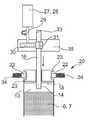
본 발명의 더 바람직한 실시예에 따라, 카트릿지 방출 장치가 가동형 램(movable ram)을 포함하고, 그러한 가동형 램은, 카트릿지의 출력 측부 상에서 음료 물질을 카트릿지로부터 외부로 가압하기 위해서 카트릿지의 입력 측부 상에서 카트릿지 내로 삽입될 수 있다는 것이 제안된다. 이어서, 램의 카트릿지측 단부는 바람직하게, 램을 카트릿지 내로 삽입할 때 램이 시작 위치 내에 위치된 플런저를 타격하고 이어서 램에 의해서 플런저가 최종 위치로 이동되는 방식으로, 카트릿지 내에 배열된 플런저와 상호 작용하도록 제공된다. 유리하게, 램이 음료 물질과 접촉되지 않고, 음료 물질이 그에 따라 저장용기로부터 혼합 챔버 내로 전달된다. 따라서, 램은 음료 준비 유닛의 일부일 수 있고 재사용될 수 있는 한편, 오염된 플런저는 카트릿지의 일부이고 그에 따라 카트릿지를 교환할 때 교체된다. 그에 따라, 음료 준비 유닛의 재오염이 효과적으로 방지된다. 소비된 카트릿지를 음료 준비 유닛으로부터 제거하기 전에, 램은 보다 특히 뒤쪽으로 그리고 카트릿지로부터 외측으로 다시 당겨진다.According to a more preferred embodiment of the present invention, the cartridge releasing device comprises a movable ram, which is configured to urge the input side of the cartridge to pressurize the beverage material from the cartridge onto the output side of the cartridge, Lt; RTI ID = 0.0 > a < / RTI > cartridge. The cartridge side end of the ram is then preferably brought into contact with the plunger and the plunger arranged in the cartridge in such a manner that the ram strikes the plunger located in the start position when the ram is inserted into the cartridge and then the plunger is moved to the final position by the ram Lt; / RTI > Advantageously, the ram is not in contact with the beverage material, and the beverage material is thereby transferred from the storage vessel into the mixing chamber. Thus, the ram can be part of the beverage preparation unit and can be reused, while the contaminated plunger is part of the cartridge and is replaced accordingly when replacing the cartridge. As a result, re-contamination of the drink preparation unit is effectively prevented. Before removing the spent cartridge from the beverage preparation unit, the ram is pulled back more particularly back and outward from the cartridge.
대안적으로, 램의 카트릿지측 단부가 플런저를 포함하는 것이 또한 원칙적으로 가능할 수 있다. 이러한 경우에, 플런저는 음료 준비 유닛의 일부이고 카트릿지의 일부가 아닐 수 있다. 그러나, 이러한 해결책은 재오염 위험으로 인해서 덜 바람직하다. 그러나, 다른 한편으로, 이러한 해결책은 상업적으로 구현될 수 있는 가능성이 더 높은데, 이는 플런저가 여기에서 일회용 제품을 나타내지 않기 때문이다.Alternatively, it is also possible in principle that the cartridge side end of the ram includes a plunger. In this case, the plunger is part of the beverage preparation unit and may not be part of the cartridge. However, such a solution is less desirable due to the risk of recontamination. However, on the other hand, this solution is more likely to be commercially implemented because the plunger does not represent a disposable product here.
본 발명의 추가적인 바람직한 실시예에 따라, 카트릿지가 삽입 측부의 영역 내에서 밀봉 요소를 가지는 것이 제안되고, 그러한 밀봉 요소는 플런저의 삽입에 의해서 개방되고, 보다 특히 밀봉 요소는 플런저가 삽입될 때 파열되는 밀봉 막을 포함한다. 밀봉 요소는 바람직하게, 적어도 음료 준비 유닛 내로의 삽입에 앞서서, 저장용기가 밀폐식으로 밀봉되게 보장하고, 그에 따라 카트릿지의 저장 및 운송 중에 음료 물질이 빠져 나올 수 없고 음료 물질의 향기가 유지된다. 램이 도입될 때 밀봉 막이 램에 의해서 파열되도록 플런저가 밀봉 요소와 음료 물질 사이의 시작 위치에 배열되는 방식으로, 밀봉 막이 바람직하게 배열된다. 카트릿지는 바람직하게 램의 삽입에 의해서 그 입력 측부 상에서 자동적으로 개방된다. 그러나, 밀봉 막이 시작 위치에 배열된 플런저와 음료 물질 사이에 배열되고, 그에 따라 램이 삽입될 때 이동 플런저에 의해서 밀봉 막이 파열되는 것을 또한 생각할 수 있을 것이다.According to a further preferred embodiment of the present invention, it is proposed that the cartridge has a sealing element in the region of the insertion side, such a sealing element is opened by insertion of the plunger, more particularly the sealing element is ruptured when the plunger is inserted And a sealing film. The sealing element preferably ensures that the storage container is hermetically sealed prior to insertion into at least the beverage preparation unit so that the beverage material can not escape during storage and transportation of the cartridge and the aroma of the beverage material is maintained. The sealing film is preferably arranged in such a manner that the plunger is arranged at the starting position between the sealing element and the beverage material so that the sealing film is ruptured by the ram when the ram is introduced. The cartridge is preferably automatically opened on its input side by insertion of the ram. However, it is also conceivable that the sealing film is arranged between the plunger and the beverage material arranged in the starting position, whereby the sealing film is ruptured by the moving plunger when the ram is inserted.
본 발명의 추가적인 바람직한 실시예에 따라서, 음료 준비 유닛이 카트릿지 내로의 램의 모터-구동 삽입을 위한 안내 유닛을 가지는 것이 제안되며, 램을 위한 안내 유닛은 램을 삽입하기 위한 직선형 또는 곡선형 안내 요소를 포함하고, 안내 유닛은 전기 선형 모터를 갖는다. 따라서, 램은 유리하게 모터-구동 방식으로 카트릿지 내로 도입될 수 있다. 이러한 경우에, 사용자는 누름 버튼 또는 기타에 의해서 삽입을 트리거(trigger)하기만 하면 된다. 곡선형 안내 요소의 이용은, 안내 유닛의 구조적 높이가 감소될 수 있다는 장점을 갖는다. 이러한 경우에, 램은 바람직하게 가요성 구조를 갖는다. 달리, 램이 강성 또는 반-강성으로 형성된다. 전기 선형 모터는 더 바람직하게 피스톤을 포함하고, 그러한 피스톤은 전기 모터(예를 들어, 3-상 비동기식 기계 또는 3-상 동기식 기계)의 구동 샤프트 상에 안착되고 기어 랙(gear rack)과 결합되며, 기어 랙은 램에 커플링되거나 이미 램의 일부이다. 피니언을 회전시키는 것에 의해서, 기어 랙이 이동되고 그에 따라 램은 카트릿지 내로 구동되거나 카트릿지로부터 외부로 이동된다. 또한, 대안으로서, 전술한 전기 구동부가, 스핀들이 피니언에 의해서 병진 운동되는 전기-모터화된 스핀들 구동부를 포함하는 것을 생각할 수 있고, 그러한 스핀들은 램에 커플링되거나 이미 램의 일부이다. 대안적으로, 전기 선형 모터는 솔레노이드 선형 모터를 포함한다. 당업자는, 유압 선형 모터가 또한 전기 선형 모터 대신에 이용될 수 있다는 것을 알 것이다.According to a further preferred embodiment of the present invention, it is proposed that the beverage preparation unit has a guide unit for motor-driven insertion of the ram into the cartridge, and the guide unit for the ram comprises a straight or curved guide element And the guide unit has an electric linear motor. Thus, the ram can be advantageously introduced into the cartridge in a motor-driven manner. In this case, the user simply has to trigger the insertion by a pushbutton or the like. The use of a curved guide element has the advantage that the structural height of the guide unit can be reduced. In this case, the ram preferably has a flexible structure. Alternatively, the ram is formed as rigid or semi-rigid. The electric linear motor more preferably comprises a piston, which is seated on a drive shaft of an electric motor (e.g. a three-phase asynchronous machine or a three-phase synchronous machine) and coupled with a gear rack , The gear rack is coupled to the ram or is already part of the ram. By rotating the pinion, the gear rack is moved so that the ram is driven into the cartridge or moved out of the cartridge. It is also contemplated that, as an alternative, the above-described electric drive includes an electromotorized spindle driver in which the spindle is translated by the pinion, such spindle being coupled to the ram or already part of the ram. Alternatively, the electric linear motor includes a solenoid linear motor. Those skilled in the art will appreciate that hydraulic linear motors may also be used in place of electric linear motors.
대안적으로, 카트릿지 방출 장치가 압축 공기를 카트릿지의 입력 측부 상에서 저장용기 내로 송풍하기 위한 압축 공기 공급원을 포함하는 것이 제안되고, 시스템은 보다 특히, 음료 물질이 압축 공기에 의해서 저장용기의 외부로 직접적으로 가압되는 방식 또는 플런저가 압축 공기에 의해서 시작 위치로부터 최종 위치 내로 이동되는 방식으로, 설계된다. 그에 따라, 전기 또는 유압 선형 모터를 이용한 전술한 해결책 대신에, 압축 공기에 의해서 직접적으로 음료 물질을 저장용기로부터 혼합 챔버 내로 가압하는 것(압축 공기는 여기에서 입력 측부 상에서 직접적으로 플런저를 가지지 않는 저장용기 내로 도입된다) 또는 이를 위해 플런저를 시작 위치로부터 최종 위치 내로 이동시키기 위해서 압축 공기에 의해서 간접적으로 음료 물질을 저장용기로부터 혼합 챔버 내로 가압하는 것(압축 공기는 여기에서 입력 측부 상에서 저장용기 내로, 즉 플런저 위로 도입된다)을 또한 생각할 수 있다. 양 변형예에서, (보다 특히 램 대신에) 압축 공기를 이용하는 것에 의해서 무엇보다도 재오염 위험이 유리하게 감소된다. 여기에서, 음료 준비 유닛이, 필요할 때 교환되는 압축 공기 카트릿지를 구비하는 것이 생각된다. 대안적으로, 압축 공기 생성을 위해서 음료 준비 유닛에 상응하는 압축기가 피팅되는(fitted) 것이 또한 생각될 수 있다. 임의의 경우에, 음료 준비 유닛이, CO2 카트릿지를 포함하는 탄산취입기(carbonator)를 가지는 경우에, 이러한 CO2 카트릿지가 또한 바람직하게 카트릿지 방출 장치를 위한 압축 공기 공급원으로서 동시에 이용된다.Alternatively, it is proposed that the cartridge discharge device includes a compressed air source for blowing compressed air into the storage container on the input side of the cartridge, and more particularly, , Or in such a manner that the plunger is moved into the final position from the starting position by the compressed air. Accordingly, instead of the above-described solution using an electric or hydraulic linear motor, direct pressurization of the beverage material from the storage vessel into the mixing chamber by compressed air (the compressed air here being stored in a plunger- Indirectly pushing the beverage material from the storage vessel into the mixing chamber (where the compressed air is introduced into the storage vessel on the input side, That is, onto the plunger). In both variants, the risk of recontamination is advantageously reduced, among other things, by using compressed air (rather than ram, in particular). Here, it is envisaged that the beverage preparation unit is provided with a compressed air cartridge which is exchanged when necessary. Alternatively, it is also conceivable that a compressor corresponding to the beverage preparation unit is fitted for producing compressed air. In any case, the beverage preparing unit, if having an insufflator carbonate (carbonator) containing CO2 Cartridge, this CO2 Cartridge is also preferably at the same time used as a compressed air source for emitting Cartridge device.
압축 공기 이용에 대한 대안으로서, 음압을 또한 이용할 수 있다. 이러한 대안적인 실시예에서, 카트릿지 방출 장치는 진공에 의해서 음료 물질을 저장용기로부터 외부로 끌어 당기기 위한 음압 장치를 가지며, 그러한 시스템은 보다 특히, 음료 물질이 진공에 의해서 저장용기의 외부로 직접적으로 흡입되는 방식으로 또는 플런저가 진공에 의해서 시작 위치로부터 최종 위치까지 이동되는 방식으로 구성된다.As an alternative to using compressed air, negative pressure can also be used. In this alternative embodiment, the cartridge discharge device has a negative pressure device for pulling the beverage material out of the storage container by vacuum, more particularly such that the beverage material is sucked directly out of the storage container by vacuum Or in such a manner that the plunger is moved from the starting position to the final position by vacuum.
본 발명의 추가적인 바람직한 실시예에 따라, 혼합 챔버가 음료 배출구를 가지는 것이 제안되며, 음료 물질과 액체의 혼합에 의해서 형성된 음료가 그러한 음료 배출구를 통해서 방출되고, 그러한 시스템은 바람직하게, 음료가 음료 배출구로부터 휴대용 용기 내로 직접적으로 도입될 수 있게 하는 방식으로 구성된다. 따라서, 유리하게, 음료 물질 및 혼합 챔버 내에서 혼합된 마무리된 음료 중 어느 것도 음료 준비 유닛의 추가적인 부분과 접촉되지 않고, 그에 따라 재오염이 방지된다. 이는, 혼합 챔버가 카트릿지의 일부이고 그에 따라 각각의 음료 생산 프로세스 이후에 교체 제품으로 교환되는 경우에 특히 그러하다.According to a further preferred embodiment of the invention, it is proposed that the mixing chamber has a beverage outlet, wherein the beverage formed by the mixing of the beverage material and the liquid is discharged through such a beverage outlet, So that it can be introduced directly into the portable container. Thus, advantageously, none of the beverage material and the finished beverage mixed in the mixing chamber comes into contact with the additional portion of the beverage preparation unit, thereby preventing recontamination. This is especially true where the mixing chamber is part of the cartridge and is therefore replaced with a replacement product after each beverage production process.
본 발명의 추가적인 바람직한 실시예에 따라, 냉각 유닛에 의해서 냉각된 액체가 액체 공급부에 공급되는 것이 제안되고, 냉각 유닛은 음료 준비 유닛의 일부 또는 음료 준비 유닛과 유효하게(active) 연결되는 별개의 냉각기의 일부이다. 그에 따라, 유리하게, 카트릿지가 냉각되지 않고 예를 들어 상온일 때에도, 저온 음료가 준비될 수 있다. 기존 냉장고에 시스템을 통합하는 것은, 냉장고의 기존 냉각 유닛이 음료 준비 유닛을 위해서 효과적으로 용이하게 또한 이용될 수 있다는 장점을 갖는다. 특히 소위 "양문형" 냉장고(또한 미국-스타일 냉장고로 종종 지칭된다)의 경우에, 시스템 통합을 위한 충분한 구조적 공간이 전방부에 존재한다. 음료 준비 유닛이 이러한 종류의 냉장고를 위한 액세서리 세트인 것을 생각할 수 있다. 냉각 유닛은 압축기 냉각 유닛, 흡수기 냉각 유닛 또는 열-전기 냉각기를 바람직하게 포함한다.According to a further preferred embodiment of the present invention it is proposed that the liquid cooled by the cooling unit is supplied to the liquid supply and the cooling unit is a separate cooler which is in active connection with a part of the beverage preparation unit or with the beverage preparation unit Lt; / RTI > Accordingly, advantageously, the cold drink can be prepared even when the cartridge is not cooled and even at room temperature, for example. Integrating the system into the existing refrigerator has the advantage that the existing refrigeration unit of the refrigerator can also be easily and effectively utilized for the beverage preparation unit. Especially in the case of so-called " side-door " refrigerators (also often referred to as US-style refrigerators), there is sufficient structural space in front for system integration. It is conceivable that the beverage preparation unit is an accessory set for this type of refrigerator. The cooling unit preferably comprises a compressor cooling unit, an absorber cooling unit or a heat-electric cooler.
본 발명의 추가적인 바람직한 실시예에 따라, 탄산취입기에 의해서 이산화탄소가 혼합된 액체가 액체 공급부에 공급되는 것이 제안된다. 보다 유리하게, 그에 따라, 시스템은 또한 이산화탄소와 혼합된 청량 음료를 생산할 수 있다. 탄산취입기는 바람직하게 음료 준비 유닛의 일부이고, 탄산취입기는 보다 특히 CO2 카트릿지를 위한 수용부 및 CO2 카트릿지로부터의 CO2와 액체를 혼합하기 위한 공급 장치를 갖는다.According to a further preferred embodiment of the present invention, it is proposed that a liquid mixed with carbon dioxide is supplied to the liquid supply by the carbonic acid injector. More advantageously, therefore, the system can also produce soft drinks mixed with carbon dioxide. A part of a group preferably beverage preparing unit carbonate blowing, has a feed device for mixing the CO2 and liquid CO2 from the receiving portion and Cartridge for a particular CO2 Cartridge than carbonate group blown.
본 발명의 추가적인 특히 바람직한 실시예에 따라, 혼합 챔버가 교체 가능 카트릿지의 일부로 형성되는 것이 제안된다. 이러한 방식으로, 음료 물질에 의한 음료 준비 유닛의 오염이 효과적으로 방지되는데, 이는 교체 가능한 단일-사용 카트릿지의 일부만이 음료 물질과 접촉되기 때문이다. 추가적인 밀봉 요소가 바람직하게 저장용기와 혼합 챔버 사이에 배열되고 카트릿지를 카트릿지 수용부 상으로 삽입할 때 또는 카트릿지 방출 장치를 활성화시킬 때 개방된다. 추가적인 밀봉 요소는 운송 또는 저장 중에 향기-밀봉 방식으로 출력 측부 상에서 카트릿지를 밀봉하는 역할을 한다. 카트릿지는 보다 특히 앞서서 더 설명된 밀봉 요소에 의해서 입력 측부 상에서 향기-밀봉 폐쇄되고, 그에 따라 저장용기는, 카트릿지를 카트릿지 수용부 내로 삽입하기 전에 그리고 보다 특히 음료 준비 프로세스의 시작 전에, 완전히 향기-밀봉 폐쇄되고, 그에 의해서 카트릿지는 예로서 긴 보관 수명을 가질 수 있다. 추가적인 밀봉 요소가, 플런저가 시작 위치로부터 최종 위치 내로 이동될 때, 저장용기 내의 압력 상승을 통해서 개방되는 그리고 보다 특히 파열되는 밀봉 막을 포함하는 것을 생각할 수 있다. 보다 유리하게, 이러한 시스템으로, 추가적인 밀봉 요소는 음료의 생산 중에 자동적으로 개방된다.According to a further particularly preferred embodiment of the invention, it is proposed that the mixing chamber is formed as part of a replaceable cartridge. In this way, contamination of the beverage preparation unit by the beverage material is effectively prevented, because only a part of the replaceable single-use cartridge is contacted with the beverage material. Additional sealing elements are preferably opened between the reservoir and the mixing chamber and open when inserting the cartridge onto the cartridge receptacle or activating the cartridge ejector. An additional sealing element serves to seal the cartridge on the output side in a perfume-tight manner during transport or storage. The cartridge is perfume-tightly closed on the input side by a sealing element described more particularly earlier in advance, so that the reservoir can be completely perfume-sealed prior to inserting the cartridge into the receptacle and more particularly before the start of the drink preparation process So that the cartridge can have a long shelf life as an example. It is contemplated that the additional sealing element includes a sealing membrane that is opened and more particularly ruptured through a pressure rise in the reservoir when the plunger is moved from its initial position into its final position. More advantageously, with such a system, the additional sealing element is automatically opened during the production of the beverage.
카트릿지의 일부로서 형성된 혼합 챔버는 바람직하게, 카트릿지가 카트릿지 수용부 내에 삽입될 때, 혼합 챔버를 액체 공급부와 연결하기 위한 신속-피팅 커플링을 갖는다. 이러한 방식으로, 혼합 챔버는 삽입 중에 액체 공급부와 자동적으로 액체 연결된다. 신속-피팅 커플링은 보다 특히 커플링 파이프 및 커플링된 상태에서 커플링 파이프를 수용하는 커플링 소켓을 가지며, 커플링 파이프 및/또는 커플링 소켓은 밀봉부를 포함하고, 및/또는 커플링 상태에서 커플링 파이프는 커플링 소켓 내로 스냅-피팅되고, 및/또는 커플링 파이프는 음료 준비 유닛의 일부이고 커플링 소켓은 혼합 챔버의 일부이다. 신속-피팅 커플링이 플러그-인 연결기, 단일 커플러, 다수 커플러, 완전 단절 커플링(clean break coupling), 폐쇄 커플링, 관통 커플링 및/또는 통과 커플링을 포함하는 것을 생각할 수 있다.The mixing chamber formed as part of the cartridge has preferably a quick-fitting coupling for connecting the mixing chamber with the liquid supply when the cartridge is inserted into the cartridge receiving portion. In this way, the mixing chamber is automatically in fluid communication with the liquid supply during insertion. The quick-fitting coupling more particularly has a coupling pipe and a coupling socket that receives the coupling pipe in a coupled state, the coupling pipe and / or coupling socket includes a seal, and / or the coupling state The coupling pipe is snap-fit into the coupling socket, and / or the coupling pipe is part of the beverage preparation unit and the coupling socket is part of the mixing chamber. It is envisioned that the quick-fitting coupling includes a plug-in coupler, a single coupler, a multiple coupler, a clean break coupling, a closed coupling, a through coupling and / or a pass coupling.
본 발명의 추가적인 특히 바람직한 실시예에 따라, 카트릿지 수용부가, 형상-피팅(form-fitting) 방식으로 카트릿지를 수용하는 형상-피팅 요소를 가지는 것이 제안되고, 카트릿지는 바람직하게 카트릿지 수용부 내에서 가압-피팅(force-fitting) 방식으로 부가적으로 유지된다. 예로서, 형상-피팅 요소는 카트릿지를 카트릿지 수용부 내로 삽입함으로써 압축되고 및/또는 결합되는 적어도 하나의 스프링 요소 및/또는 멈춤쇠 요소를 포함하고, 카트릿지 수용부가 바람직하게 리드-인 모따기부(lead-in chamfer) 및/또는 위치결정 보조부(positioning aid)를 갖는 것을 생각할 수 있다. 카트릿지 수용부는 바람직하게, 카트릿지를 그 입력 측부의 영역 내에서 유지하는 상부 형상-피팅 요소, 및 카트릿지를 출력 측부 및/또는 혼합 챔버의 영역 내에서 유지하는 하부 형상-피팅 요소를 갖는다.According to a further particularly preferred embodiment of the present invention, it is proposed that the cartridge receiving portion has a shape-fitting element for receiving the cartridge in a form-fitting manner, and the cartridge preferably comprises a press- And is additionally maintained in a force-fitting manner. By way of example, the shape-fitting element comprises at least one spring element and / or detent element that is compressed and / or engaged by inserting the cartridge into the cartridge receptacle, wherein the cartridge receptacle is preferably a lead- -in chamfer and / or a positioning aid. The cartridge receiving portion preferably has an upper shape-fitting element that holds the cartridge within the region of its input side, and a lower shape-fitting element that holds the cartridge within the region of the output side and / or mixing chamber.
카트릿지가, 상부 형상-피팅 요소와 하부 형상-피팅 요소 사이에서, 상부 및 하부 형상-피팅 요소의 영역 내의 직경보다 크거나 작은 직경을 가질 수 있도록, 카트릿지 수용부가 바람직하게 구성된다. 이러한 방식으로, 적어도 중간 영역 내에서, 즉 상부 및 하부 형상-피팅 요소가 결합되지 않는 그러한 영역 내에서, 상이한 기하형태적 구성을 가지는 카트릿지가 이용될 수 있다. 따라서, 상이한 부피의 저장용기들을 가지는 카트릿지들이 보다 특히 이용될 수 있다. 예로서, 주정-함유(spirit-containing) 음료를 위한 카트릿지는 무-알코올, 카페인-함유 및 탄산화된 청량 음료의 경우보다 적은 양의 음료 물질로 준비될 수 있다.The cartridge receiving portion is preferably configured such that the cartridge can have a diameter larger or smaller than the diameter in the region of the upper and lower shape-fitting elements, between the upper shape-fitting element and the lower shape-fitting element. In this way, cartridges having different geometrical configurations can be used, at least in the middle area, i.e. in such areas where the upper and lower shape-fitting elements are not engaged. Thus, cartridges having different volumes of storage containers can be used more particularly. By way of example, cartridges for spirit-containing beverages may be prepared with less beverage material in the case of non-alcoholic, caffeine-containing and carbonated soft drinks.
당업자는, 혼합 챔버가 또한 대안적으로 음료 준비 유닛의 일부일 수 있다는 것을 이해한다. 이러한 시나리오에서, 음료 물질의 잔류물이 혼합 챔버 내에 남지 않도록, 혼합 챔버는 각각의 음료 생산 이후에 물로 관통 플러싱되어야 한다.Those skilled in the art understand that the mixing chamber can also alternatively be part of the beverage preparation unit. In such a scenario, the mixing chamber must be flushed through with water after each beverage production so that the residue of beverage material is not left in the mixing chamber.
본 발명의 추가적인 특히 바람직한 실시예에 따라, 음료 물질을 저장용기로부터 혼합 챔버 내로 전달하기 위해서 카트릿지 방출 장치가 작용하는 카트릿지 내측에 스크린 요소(screen element)를 배열하고, 스크린 요소를 카트릿지 방출 장치와 음료 물질 사이에 배열하는 것이 제안된다. 유리하게, 카트릿지 방출 장치는 스크린 요소에 의해서 음료 물질로부터 절연되고, 그에 따라 카트릿지 방출 장치를 통한 음료 준비 기계의 재오염이 발생될 수 없다. 그럼에도 불구하고 저장용기를 비울 수 있도록, 스크린 요소는 가요성 구조물을 가지며 보다 특히 벨로우즈(bellows) 또는 연성 백 요소로서 설계된다. 이어서, 스크린 요소는 항상 저장용기 내측에 배열되고, 음료 물질은 벨로우즈 또는 연성 백 요소 내측에 배열된다. 카트릿지 방출 장치, 그에 따라 보다 특히 램 또는 압축 공기가 벨로우즈 또는 백 요소에 작용할 때, 벨로우즈가 저장용기 내측에서 압궤되거나(collapsed) 백 요소가 저장용기 내측에서 압축되며, 그에 따라 음료 물질이 저장용기로부터 혼합 챔버 내로 전달된다. 다시 말해서: 벨로우즈 또는 연성 백 요소는 시작 위치에서 카트릿지의 출력 측부로부터 적어도 부분적으로 카트릿지 벽에 평행하게 카트릿지의 입력 측부까지 연장되고, 음료 생산 프로세스 중에 카트릿지 방출 장치에 의해서 출력 측부를 향해서 이동된다.According to a further particularly preferred embodiment of the invention, a screen element is arranged inside the cartridge in which the cartridge discharging device acts in order to deliver the beverage material from the storage container into the mixing chamber, It is proposed to arrange between the materials. Advantageously, the cartridge dispensing device is insulated from the beverage material by the screen element, and therefore re-contamination of the beverage preparation machine through the cartridge dispensing device can not occur. Nevertheless, in order to be able to empty the storage container, the screen element has a flexible structure, more particularly designed as a bellows or a soft bag element. Then, the screen element is always arranged inside the storage container, and the beverage material is arranged inside the bellows or soft bag element. When the cartridge discharge device, and more particularly the ram or compressed air, acts on the bellows or bag element, the bellows collapsed inside the storage container and the bag element is compressed inside the storage container, Into the mixing chamber. In other words: the bellows or soft bag element extends from the output side of the cartridge at least partially from the output side of the cartridge to the input side of the cartridge parallel to the cartridge wall, and is moved towards the output side by the cartridge discharge device during the beverage production process.
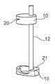
전술한 목적을 달성하기 위한 본 발명의 추가적인 대상은 보다 특히 음료를 생산하기 위한 본 발명에 따른 시스템을 위한 카트릿지이고, 그러한 카트릿지는 음료 준비 유닛의 카트릿지 수용부 내로 삽입될 수 있고, 카트릿지는 음료 물질로 충진된 저장용기를 갖는다. 저장용기는 바람직하게, 1인분의 음료수, 예로서 희망 음료로 충진된 음료수 잔을 생산하는데 필요한 음료 물질의 미리-1인분화된 양으로 충진된다. 음료수 잔은 전형적으로 0.1 리터, 0.2 리터, 0.3 리터, 0.33 리터, 0.35 리터, 0.366 리터, 0.5 리터, 또는 1 리터의 액체를 유지한다. 더 유리하게, 사용자는 희망 음료를 생성하기 위한 상응 음료 물질을 포함하는 특정 카트릿지를 선택하는 것, 그러한 카트릿지를 카트릿지 수용부 내에 삽입하는 것, 그리고 음료 준비 유닛 상에서 음료 생산 프로세스를 시작하는 것에 의해서, 상이한 음료들을 용이하게 생성할 수 있다. 이어서, 음료는 자동적으로 음료수 용기 내로 지향되고 그에 따라 사용자에게 제공된다. 이어서, 소비된 카트릿지가 제거되고 폐기된다. 본 발명에 따른 의미 내에서 음료 준비 유닛의 재오염이 방지되기 때문에, 유리하게, 새로운 음료를 제조하기 전에 다른 향(flavor)으로 플러싱 또는 헹굼할 필요가 없다.A further object of the present invention for achieving the above object is a cartridge for a system according to the invention for producing more particularly drinks, such a cartridge being insertable into a cartridge receiving portion of a beverage preparation unit, Lt; / RTI > The storage vessel is preferably filled with a pre-1 portion of the beverage material required to produce one serving of beverage, for example, a beverage drink filled with the beverage of choice. Drink glasses typically hold 0.1 liter, 0.2 liter, 0.3 liter, 0.33 liter, 0.35 liter, 0.366 liter, 0.5 liter, or 1 liter of liquid. More advantageously, the user may select a particular cartridge containing the corresponding beverage material to create the desired beverage, insert such cartridge into the receptacle, and initiate the beverage production process on the beverage preparation unit, Different beverages can be easily generated. The beverage is then automatically directed into the beverage container and provided to the user accordingly. The spent cartridges are then removed and discarded. Advantageously, there is no need to flush or rinse with a different flavor before making a new beverage, since re-fouling of the beverage preparation unit within the meaning of the present invention is prevented.
음료 물질은 바람직하게, 청량 음료, 설탕 첨가 음료수, 과일 주스, 과일 즙, 과일 주스 농축물, 과일 스프리처(spritzer), 레모네이드, 거품 음료수, 에너지 음료수, 등장액 음료수, 맥주, 혼합 맥주 음료수, 식탁용 물, 거품 음료소, 광천수, 스프리츠, 알코올이 든 청량음료, 과일 와인, 야채 주스, 야채 즙, 스파클링 와인, 과일 스파클링 와인, 알코올 혼합 음료수, 와인, 와인 스프리처, 칵테일, 커피, 홍차, 아이스 티, 우유, 초콜릿 음료수, 카페인 첨가된, 알콜성, (과일) 설탕-함유 및/또는 탄산 음료 그리고 그 혼합물 및 변형물과 같은, 액체 음료 물질을 포함한다. 또한, 예비-혼합 성분이 혼합 챔버 내에서 물과 혼합될 때에만 음료가 발생되도록, 음료 물질이 보다 특히 전술한 음료를 위한 유체 예비-혼합 성분만을 포함하는 것을 생각할 수 있다. 또한, 음료 물질이, 가용성 분말, 셔벗(sherbet) 분말 또는 기타와 같은, 미립자 물질을 부가적으로 또는 배타적으로 포함하는 것을 생각할 수 있다.The beverage substance is preferably selected from the group consisting of soft drinks, sugar added beverages, fruit juices, fruit juices, fruit juice concentrates, fruit spritzer, lemonade, foam drinks, energy beverages, Alcohol, soft drink with alcohol, fruit wine, vegetable juice, vegetable juice, sparkling wine, fruit sparkling wine, alcohol mixed drink, wine, wine spritzer, cocktail, coffee, tea, ice Liquid beverage materials such as tea, milk, chocolate beverages, caffeinated, alcoholic, (fruit) sugar-containing and / or carbonated beverages and mixtures and variants thereof. It is also conceivable that the beverage material comprises more than only the fluid pre-mix components for the aforementioned beverage, so that the beverage is only produced when the pre-mix component is mixed with water in the mixing chamber. It is also contemplated that the beverage material may additionally or exclusively include particulate matter, such as soluble powder, sherbet powder, or the like.
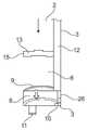
본 발명의 특히 바람직한 실시예에 따라, 카트릿지가, 저장용기 내에 배열되고 카트릿지의 입력 측부에 근접한 시작 위치와 입력 측부로부터 출력 측부를 향해서 변위되는 최종 위치 사이에서 이동될 수 있는 플런저를 갖는 것이 제안된다. 이러한 방식으로, 음료 물질은 저장용기로부터 혼합 챔버 내로 이송된다. 혼합 챔버는 바람직하게 카트릿지의 일부이고 보다 특히, 카트릿지가 카트릿지 수용부 내로 삽입될 때, 저장용기 아래에 배열된다.According to a particularly preferred embodiment of the invention it is proposed that the cartridge has a plunger which is arranged in the storage container and can be moved between a starting position close to the input side of the cartridge and a final position displaced from the input side towards the output side . In this manner, the beverage material is transferred from the storage vessel into the mixing chamber. The mixing chamber is preferably part of the cartridge and more particularly when the cartridge is inserted into the cartridge receiving portion, it is arranged below the storage container.
플런저는 바람직하게, 보다 특히 저장용기의 벽과 플런저 사이의 간극을 밀봉하는 가요성 원주방향 밀봉 립 형태의, 밀봉 장치를 갖는다.The plunger preferably has a sealing device, more particularly in the form of a flexible circumferential seal lip sealing the gap between the wall of the reservoir and the plunger.
플런저는 바람직하게 음료 준비 유닛의 램을 수용하기 위한 램 수용부를 가지며, 플런저는, 음료 물질이 저장용기로부터 액체 방향으로 저장용기 뒤쪽에 그리고 보다 특히 저장용기 아래에 배열된 혼합 챔버 내로 지향되도록 램을 저장용기 내로 삽입하는 것에 의해서 시작 위치로부터 최종 위치까지 이동될 수 있도록 설계된다. 램 수용부는 예로서, 램을 플런저 상에서 센터링시키고 램이 횡방향으로 활주되는 것을 방지하는, 깔때기-형상의 수용부, 함몰부, 돌출부 또는 기타일 수 있다.The plunger preferably has a ram receptacle for receiving the ram of the beverage preparation unit and the plunger is adapted to urge the ram so that the beverage material is directed from the reservoir in a liquid direction behind the reservoir and more particularly into a mixing chamber arranged below the reservoir. And can be moved from the starting position to the end position by inserting into the storage container. The ram receiving portion may be, for example, a funnel-shaped receiving portion, depression, protrusion or the like, which centers the ram on the plunger and prevents the ram from sliding in the transverse direction.
본 발명의 바람직한 실시예에 따라, 카트릿지가 삽입 측부의 영역 내에서 밀봉 요소를 가지고, 그러한 밀봉 요소는 플런저의 삽입에 의해서 개방되고, 보다 특히 밀봉 요소는 플런저가 삽입될 때 파열되는 밀봉 막을 포함하는 것이 제안된다. 추가적인 밀봉 요소가 저장용기와 혼합 챔버 사이에 배열되고, 그러한 추가적인 밀봉 요소는, 카트릿지를 카트릿지 수용부 상으로 삽입하는 동안 또는 카트릿지 방출 장치의 활성화 동안 개방된다. 추가적인 밀봉 요소는 또한 바람직하게, 플런저가 시작 위치로부터 최종 위치 내로 이동될 때, 저장용기 내의 압력 상승을 통해서 개방되는 그리고 보다 특히 파열되는 밀봉 막을 포함한다. 구체적으로 이미 전술한 바와 같이, 밀봉 요소 및 추가적인 밀봉 요소는 운송 또는 저장 중에 향기-밀봉 방식으로 저장용기를 폐쇄하는 역할을 한다.According to a preferred embodiment of the present invention, the cartridge has a sealing element in the region of the insertion side, such a sealing element is opened by insertion of a plunger, more particularly the sealing element comprises a sealing membrane ruptured when the plunger is inserted Is proposed. Additional sealing elements are arranged between the reservoir and the mixing chamber, and such additional sealing elements are opened during insertion of the cartridge onto the cartridge receiving portion or during activation of the cartridge ejector. The additional sealing element also preferably includes a sealing membrane that is open and more specifically ruptured through a pressure rise in the reservoir vessel when the plunger is moved from its initial position into its final position. Specifically, as already mentioned above, the sealing element and the additional sealing element serve to close the storage vessel in a perfume-tight manner during transport or storage.
카트릿지는 바람직하게 혼합 챔버를 가지며, 혼합 챔버는 음료 준비 유닛의 액체 공급부와 액체 연결될 수 있다. 혼합 챔버는 바람직하게 여기에서, 카트릿지가 카트릿지 수용부 내로 삽입될 때 혼합 챔버를 액체 공급부에 연결하기 위한 신속-피팅 커플링을 포함한다.The cartridge preferably has a mixing chamber and the mixing chamber can be in fluid communication with the liquid supply of the beverage preparation unit. The mixing chamber preferably includes a quick-fitting coupling for coupling the mixing chamber to the liquid supply when the cartridge is inserted into the cartridge receiving portion.
혼합 챔버는 바람직하게 음료 배출구를 가지고, 음료 물질과 액체의 혼합에 의해서 형성된 음료가 그러한 음료 배출구를 통해서 분배되고, 시스템은 바람직하게, 음료가 음료 배출구로부터 휴대용 용기 내로 직접적으로 지향될 수 있게 하는 방식으로 설계된다. 유리하게, 그에 따라, 음료 물질 및 혼합 챔버 내에서 음료 물질로부터 생산된 음료 중 어느 것도 음료 준비 유닛의 일부와 직접 접촉되도록 전달되지 않고, 그에 따라 재오염이 적극적으로 방지될 수 있다.The mixing chamber preferably has a beverage outlet, wherein the beverage formed by the mixing of the beverage material and the liquid is dispensed through such beverage outlet, and the system is preferably configured such that the beverage can be directed directly into the hand- . Advantageously, neither the beverage material nor the beverage produced from the beverage material in the mixing chamber is delivered to come into direct contact with a portion of the beverage preparation unit, thereby positively preventing recontamination.
본 발명의 바람직한 실시예에 따라, 카트릿지를 음료 준비 유닛 내로 삽입하는 동안 카트릿지 수용부와 상호 작용하여 카트릿지를 카트릿지 수용부 내에서 유지하는 적어도 하나의 연결 요소를 카트릿지가 갖는 것이 제안된다. 연결 요소가, 보다 특히 카트릿지 수용부의 스프링 및/또는 멈춤쇠 요소 형태인, 형상-피팅 요소와 결합되는 삽입 요소를 포함하는 것을 생각할 수 있다.According to a preferred embodiment of the present invention, it is proposed that the cartridge has at least one connecting element that interacts with the receptacle receiving portion during insertion of the receptacle into the beverage preparation unit to hold the receptacle in the receptacle receptacle. It is conceivable that the connecting element comprises an insertion element which is more particularly associated with a shape-fitting element, in the form of a spring and / or detent element of the cartridge receiving part.
본 발명의 바람직한 실시예에 따라, 카트릿지가 입력 측부의 영역 내의 상부 연결 요소 및 출력 측부 및/또는 혼합 챔버의 영역 내의 하부 연결 요소를 가지는 것이 제안된다. 카트릿지는 바람직하게, 입력 측부와 출력 측부 사이의 중간 영역 내에서, 입력 측부 및/또는 출력 측부의 영역 내의 카트릿지의 직경보다 크거나 작은 직경을 갖는다. 이러한 방식으로, 상이한 부피의 저장용기들을 가지는 카트릿지들이 카트릿지 수용부 내로 삽입될 수 있다. 입력 측부의 영역 내의 카트릿지의 직경이 혼합 챔버 및/또는 출력 측부의 영역 내의 카트릿지의 직경과 실질적으로 동일한 것을 생각할 수 있다. 그러나, 대안적으로, 입력 측부 상의 직경이 또한 출력 측부 상의 직경과 상이할 수 있고, 그에 따라 회전방향 잠금부(rotational lock)가 생성되고 카트릿지 수용부 내로의 카트릿지의 정확한 삽입이 보장된다.According to a preferred embodiment of the invention, it is proposed that the cartridge has a lower connecting element in the region of the upper connecting element and the output side and / or the mixing chamber in the region of the input side. The cartridge preferably has a diameter that is larger or smaller than the diameter of the cartridge in the area of the input side and / or output side within an intermediate region between the input side and the output side. In this way, the cartridges having different volumes of storage containers can be inserted into the cartridge receiving portion. It is conceivable that the diameter of the cartridge in the area of the input side is substantially the same as the diameter of the cartridge in the area of the mixing chamber and / or the output side. Alternatively, however, the diameter on the input side may also differ from the diameter on the output side, thereby creating a rotational lock and ensuring correct insertion of the cartridge into the cartridge receiving portion.
카트릿지는 바람직하게 그 길이방향 축을 따라 회전 대칭적으로 형성되고, 그에 따라 사용자가 카트릿지 수용부 내로의 카트릿지를 삽입하는 것이 더 용이해진다.The cartridge is preferably formed rotationally symmetrically along its longitudinal axis, thereby making it easier for the user to insert the cartridge into the cartridge receiving portion.
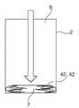
본 발명의 바람직한 실시예에 따라, 스크린 요소가 카트릿지 내측에 배열되고, 스크린 요소가 바람직하게 저장용기 내측에 배열된 벨로우즈 또는 연성 백 요소를 포함하고, 음료 물질이 벨로우즈 또는 연성 백 요소 내측에 배열되는 것이 제안된다. 벨로우즈 또는 백 요소는 보다 특히 유체-불침투성 및/또는 가스-불침투성 호일로 구성된다. 벨로우즈 또는 백 요소는 바람직하게 카트릿지의 출력 측부의 영역 내에서 카트릿지에 부착된다.According to a preferred embodiment of the present invention, a screen element is arranged inside the cartridge and the screen element preferably comprises a bellows or a soft bag element arranged inside the storage container and the beverage material is arranged inside the bellows or soft bag element Is proposed. The bellows or back element is more particularly comprised of a fluid-impermeable and / or gas-impermeable foil. The bellows or back element is preferably attached to the cartridge within the region of the output side of the cartridge.
본 발명의 추가적인 대상은 보다 특히 음료 준비를 위한 본 발명에 따른 시스템을 위한 음료 준비 유닛이고, 음료 준비 유닛은, 보다 특히 본 발명에 따른 카트릿지가 가역적으로 내부에 삽입될 수 있는 카트릿지 수용부, 저장용기로부터 혼합 챔버 내로 음료 물질이 적어도 부분적으로 전달되게 하는 카트릿지 방출 장치, 그리고 혼합 챔버 내로 개방되는 액체 공급부를 갖는다.A further object of the invention is a beverage preparation unit for a system according to the invention, more particularly for beverage preparation, wherein the beverage preparation unit comprises, more particularly, a cartridge receptacle in which the cartridge according to the invention is reversibly insertable therein, A cartridge discharge device for causing the beverage material to be at least partially transferred from the container into the mixing chamber, and a liquid supply portion which opens into the mixing chamber.
본 발명의 바람직한 실시예에 따라, 카트릿지 방출 장치가 가동형 램을 포함하는 것이 제안되고, 그러한 가동형 램은, 카트릿지의 출력 측부 상에서 음료 물질을 카트릿지로부터 외부로 가압하기 위해서 카트릿지의 입력 측부 상에서 카트릿지 내로 삽입될 수 있다. 음료 준비 유닛은 바람직하게 카트릿지 내로의 램의 모터-구동 공급을 위한 안내 유닛을 가지고, 램의 안내 유닛은 램 삽입을 위한 직선형 또는 곡선형 안내 요소를 포함하고, 안내 유닛은 전기 또는 유압 선형 모터 그리고 보다 특히 스핀들 구동부를 갖는다.According to a preferred embodiment of the present invention, it is proposed that the cartridge discharge device comprises a movable ram, which is configured to move the cartridge from the cartridge side on the input side of the cartridge to pressurize the beverage material from the cartridge onto the output side of the cartridge, Lt; / RTI > The beverage preparation unit preferably has a guide unit for motor-driven supply of the ram into the cartridge, the guide unit of the ram including a linear or curved guide element for ram insertion, the guide unit comprising an electric or hydraulic linear motor and More particularly a spindle driving portion.
본 발명의 바람직한 실시예에 따라, 음료 준비 유닛이 혼합 챔버를 포함하고, 혼합 챔버가 음료 준비 유닛의 나머지로부터 제거될 수 있는 것이 제안된다. 이러한 실시예에서, 혼합 챔버는 카트릿지의 일부가 아니고, 카트릿지로부터 음료 준비 유닛 내로 독립적으로 삽입될 수 있고 (청소 및 유지보수를 위해서) 제거될 수 있다. 혼합 챔버는 유리하게 수 차례 사용될 수 있다. 각각의 음료 생산 프로세스 이후에 또는 특정 수의 음료 생산 프로세스 이후에 혼합 챔버를 세척하기 위한 자동 헹굼 및 세척 메커니즘을 가지는 음료 준비 유닛을 생각할 수 있다.According to a preferred embodiment of the present invention it is proposed that the beverage preparation unit comprises a mixing chamber and the mixing chamber can be removed from the rest of the beverage preparation unit. In this embodiment, the mixing chamber is not part of the cartridge, but can be inserted independently (for cleaning and maintenance) from the cartridge into the beverage preparation unit and removed. The mixing chamber may be advantageously used several times. A beverage preparation unit having an automatic rinsing and cleaning mechanism for cleaning the mixing chamber after each beverage production process or after a certain number of beverage production processes can be envisaged.
음료 준비 유닛이, 액체 공급부에 공급되는 액체를 냉각하기 위한 냉각 시스템을 가지는 것을 생각할 수 있다.It is conceivable that the beverage preparation unit has a cooling system for cooling the liquid supplied to the liquid supply part.
본 발명의 추가적인 대상은, 보다 특히 본 발명에 따른 시스템으로, 음료를 생산하는 방법이고, 그러한 방법은:A further object of the present invention is a method for producing a beverage, more particularly with a system according to the invention, comprising:
- 음료 물질이 충진된 카트릿지를 음료 준비 유닛의 카트릿지 수용부 내로 삽입하는 단계,- inserting the beverage-filled cartridge into the cartridge receiving portion of the beverage preparation unit,
- 음료 물질을 카트릿지 방출 장치에 의해서 카트릿지의 저장용기로부터 혼합 챔버 내로 전달하는 단계,- transferring the beverage material from the reservoir of the cartridge into the mixing chamber by means of a cartridge discharge device,
- 액체 공급부에 의해서 액체를 혼합 챔버 내로 공급하는 단계,- supplying liquid into the mixing chamber by the liquid supply,
- 음료 물질을 액체와 혼합함으로써 혼합 챔버 내에서 생산된 음료를 음료 배출구에 의해서 방출하는 단계를 포함한다.- releasing the beverage produced in the mixing chamber by mixing with the liquid by means of the beverage outlet.
본 발명에 따른 방법은, 전술한 발명에 따른 시스템과 같이, 음료 물질과의 혼합을 위해서 공급되는 액체가 저장용기 내로 지향되지 않고 혼합 챔버 내로 지향됨으로 인해서, 음료 준비 유닛의 재오염이 실질적으로 방지되는, 종래 기술보다 우수한 장점을 갖는다. 액체가 음료 물질의 전달을 위해서 이용되지 않기 때문에, 음료 물질은 바람직하게 플런저에 의해서 저장용기로부터 혼합 챔버 내로 가압되고, 그에 의해서 플런저는 카트릿지 방출 장치에 의해서 시작 위치로부터 최종 위치로 이동된다. 플런저가 여기에서, 플런저에 작용하는 램 형태인 카트릿지 방출 장치에 의해서 또는 압축 공기에 의해서 이동되는 것을 생각할 수 있다. 램은 바람직하게 안내 유닛에 의해서 카트릿지 내로 모터-구동 삽입되고, 이어서 플런저에 작용하여 플런저를 시작 위치로부터 최종 위치 내로 이동시킨다.The method according to the present invention is advantageous in that the liquid supplied for mixing with the beverage material, such as the system according to the above-described invention, is directed into the mixing chamber without being directed into the storage vessel, Which is advantageous over the prior art. Since the liquid is not used for delivery of the beverage material, the beverage material is preferably pumped from the reservoir into the mixing chamber by the plunger, whereby the plunger is moved from the start position to the end position by the cartridge discharge device. It is conceivable here that the plunger is moved by means of a cartridge ejector, which is a ram in the form of a plunger, or by compressed air. The ram is preferably motor-driven inserted into the cartridge by the guide unit, and then acts on the plunger to move the plunger from its initial position into its final position.
또한, 대안으로서, 음료 물질이 압축 공기 또는 음압에 의해서 저장용기로부터 혼합 챔버 내로 전달되는 것을 생각할 수 있다.It is further contemplated that, alternatively, the beverage material is delivered from the storage vessel into the mixing chamber by compressed air or negative pressure.
본 발명의 바람직한 실시예에 따라, 액체가 혼합 챔버 내로 유동되기 전에, 냉각 및/또는 탄산 취입되는 것이 제안된다.According to a preferred embodiment of the present invention, it is proposed that the liquid is cooled and / or carbonated before being flowed into the mixing chamber.
본 발명의 추가적인 바람직한 실시예에 따라, 램을 카트릿지 내로 삽입하는 동안 카트릿지를 밀봉하는 밀봉 요소가 개방되고, 밀봉 요소가 바람직하게 램에 의해서 파열되는 밀봉 막을 포함하는 것이 제안된다. 음료 물질을 혼합 챔버를 향해서 전달하는 것에 의해서, 저장용기와 혼합 챔버 사이의 추가적인 밀봉 요소가 개방되고, 추가적인 밀봉 요소가 바람직하게 저장용기 내의 압력 상승에 의해서 파열되는 밀봉 막을 포함하는 것을 생각할 수 있다.According to a further preferred embodiment of the invention it is proposed that the sealing element sealing the cartridge during opening of the ram into the cartridge is opened and the sealing element preferably comprises a sealing film ruptured by the ram. It is conceivable that the additional sealing element between the storage vessel and the mixing chamber is opened by conveying the beverage material towards the mixing chamber and the additional sealing element preferably comprises a sealing membrane ruptured by a pressure rise in the reservoir vessel.
본 발명의 추가적인 바람직한 실시예에 따라, 음료 물질을 저장용기로부터 혼합 챔버 내로 전달하기 위해서 카트릿지 방출 장치가 카트릿지 내측에 배열된 스크린 요소에 작용하고, 스크린 요소가 이러한 단계 중에 접히거나 압축되는 것이 제안된다.In accordance with a further preferred embodiment of the present invention it is proposed that a cartridge discharge device acts on a screen element arranged inside the cartridge to deliver the beverage material from the storage container into the mixing chamber and the screen element is folded or compressed during this step .
본 발명의 추가적인 상세 내용, 특징 및 장점이 도면으로부터 그리고 도면을 참조한 바람직한 실시예에 관한 이하의 설명으로부터 명확해진다. 도면은 단지 예로서 주어진 본 발명의 실시예를 도시하고 본질적인 발명의 개념을 제한하지 않는다.Further details, features and advantages of the present invention will become apparent from the following description of preferred embodiments with reference to the drawings and to the drawings. The drawings illustrate embodiments of the invention given by way of example only and are not intended to limit the inventive concept of the invention.
도 1은 본 발명의 예시적인 실시예에 따른 시스템, 카트릿지, 음료 준비 유닛 및 음료 생산 방법의 개략적 단면도를 도시한다.
도 2a는 본 발명의 제1의 예시적인 실시예에 따른 카트릿지의 상세도를 도시한다.
도 2b는 본 발명의 제1의 예시적인 실시예에 따른 음료 준비 유닛의 상세도를 도시한다.
도 2c는 도 2a에 도시된 카트릿지가 도 2b에 도시된 음료 준비 유닛 내로 삽입된 개략도를 도시한다.
도 3은 본 발명의 예시적인 제2 실시예에 따른 음료 생산을 위한 시스템 및 방법을 도시한다.
도 4는 본 발명의 제1 실시예에 따른 음료 생산을 위한 시스템 및 방법을 도시한다.
도 5는 본 발명의 예시적인 제3 실시예에 따른 음료 생산을 위한 시스템 및 방법을 도시한다.
도 6a 및 도 6b는 본 발명의 예시적인 제4 실시예에 따른 음료 생산을 위한 시스템 및 방법을 도시한다.
도 7a 및 도 7b는 본 발명의 예시적인 제5 실시예에 따른 음료 생산을 위한 시스템 및 방법을 도시한다.1 shows a schematic cross-sectional view of a system, a cartridge, a beverage preparation unit and a beverage production method according to an exemplary embodiment of the present invention.
2A shows a detailed view of a cartridge according to a first exemplary embodiment of the present invention.
2B shows a detailed view of the beverage preparation unit according to the first exemplary embodiment of the present invention.
FIG. 2C shows a schematic view in which the cartridge shown in FIG. 2A is inserted into the beverage preparation unit shown in FIG. 2B.
Figure 3 shows a system and method for beverage production according to a second exemplary embodiment of the present invention.
Figure 4 shows a system and method for beverage production according to a first embodiment of the present invention.
Figure 5 illustrates a system and method for beverage production according to an exemplary third embodiment of the present invention.
6A and 6B illustrate a system and method for beverage production according to an exemplary fourth embodiment of the present invention.
7A and 7B illustrate a system and method for beverage production according to an exemplary fifth embodiment of the present invention.
여러 도면에서, 동일한 부분들은 항상 동일한 참조 번호를 가지고, 그에 따라, 일반적으로 한 차례만 언급되거나 나열된다.In the various figures, the same parts always have the same reference number and are therefore generally referred to or listed only once.
도 1은 본 발명의 예시적인 제1 실시예에 따른 본 발명에 따른 방법에 의해서 음료를 생산하기 위한, 본 발명에 따른 카트릿지(2) 및 음료 준비 유닛(3)을 본 발명에 따라 가지는, 본 발명에 따른 시스템(1)의 개략적 단면도를 도시한다.Fig. 1 is a sectional view of a beverage preparation unit according to the present invention, having a
본 시스템(1)은 음료 준비 유닛(3)을 포함하고, 그러한 음료 준비 유닛(3) 내에는 특정 음료 물질(7)로 충진된 교체 가능 카트릿지(2)가 삽입될 수 있다. 음료 물질(7) 및, 적용 가능한 경우에, 부가적인 물 공급원에 의해서, 음료 준비 유닛(3) 내측에서 상응 음료가 생산된다. 이어서, 카트릿지(2)는 바람직하게, 목표로 하는 1인분의 음료수, 예로서 희망 음료로 충진된 음료수 잔을 생산하는데 필요한 음료 물질(7)의 미리-1인분화된 양으로 충진된다. 상이한 음료들을 생산하기 위한 상이한 음료 물질들(7)로 충진된 복수의 상이한 카트릿지들(2)이 특히 이용 가능하다. 시스템(1)의 사용자가 특정 음료를 마시고자 할 때, 사용자는 단지 복수의 상이한 카트릿지들(2) 중에서 희망 음료를 생산하기 위한 상응 음료 물질(7)을 포함하는 해당 카트릿지(2)만을 선택하고, 그러한 카트릿지를 음료 준비 유닛(3)의 카트릿지 수용부(10) 내로 삽입하고, 그리고, 적절한 경우에, 예를 들어, 누름 버튼을 누르는 것, 터치-감응형 디스플레이를 적절하게 터치하는 것에 의해서, 동작이나 음성 제어를 통해서, 또는 모바일 폰 상의 적절한 앱(app)에 의해서, 음료 준비 유닛(3) 상에서 음료 생산 프로세스를 시작하기만 하면 된다. 또한, 카트릿지 수용부(10) 내로의 새로운 카트릿지(2)의 삽입이 인식될 때 음료 생산 프로세스가 자동적으로 제어되는 것을 생각할 수 있다. 전술한 경우의 각각에서, 희망 음료는 이어서 자동적으로 생산되고, 음료수 용기 내로 지향되고 그에 따라 사용자에게 제공된다. 이어서, 소비된 카트릿지(2)가 제거되고 폐기된다. 이어서, 추가적인 음료를 생산하기 위해서, 임의의 희망하는 새로운 카트릿지(2)로 다시 충진되도록 음료 준비 유닛(3)이 준비된다.The present system 1 comprises a
음료 물질(7)은 바람직하게, 카페인 첨가된, 탄산 취입된, 과일- 및 설탕-함유 레모네이드 및 주스와 같은 청량 음료, 맥주 (혼합) 음료 또는 다른 알코올성 또는 비-알코올성 혼합 음료를 위한 액체 예비-혼합 성분을 포함한다.The
카트릿지(2)는 (도면에서 상단에 배열된) 입력 측부(4) 및 (도면에서 하단에 배열된) 출력 측부(5)를 가지는 원통형 컨테이너를 포함한다. 컨테이너 내측에서, 카트릿지(2)는, 액체 음료 물질(7)로 충진된 저장용기(6)를 갖는다. 출력 측부(5)의 영역에서, 카트릿지(2)는, 컨테이너에 고정 연결된 혼합 챔버(8)를 갖는다(즉, 혼합 챔버는 여기에서 카트릿지(2)의 일부이다). 저장용기(6)는 이러한 영역 내에서 전달 개구부(9) 내로 개방되고, 그러한 전달 개구부를 통해서 음료 물질이 저장용기(6)로부터 혼합 챔버(8) 내로 전달될 수 있다. 본 예에서 저장용기(6)의 기부는 깔때기-형상이고, 전달 개구부(9)는 깔때기-형상의 기부의 중심에 배열된다. 이어서, 전달 개구부(9)는, 혼합 챔버(8) 내로 돌출되는 선택적인 짧은 파이프 부재 내로 연장된다.The
혼합 챔버(8)는 음료 배출구(11)를 가지며, 그러한 음료 배출구를 통해서 혼합 챔버(8) 내측에서 생산된 음료가 혼합 챔버(8)를 빠져 나가고 보다 특히 음료수 용기(미도시) 내로 직접적으로, 다시 말해서 음료 준비 유닛(3)의 일부가 음료와 접촉되지 않고, 전달된다. 이러한 방식으로, 음료 준비 유닛(3)의 재오염이 방지된다. 음료수 용기는 보다 특히 음료 배출구(11) 바로 아래에 배열된다.The mixing
혼합 챔버(8)는 신속-피팅 커플링(26)을 가지며, 그러한 신속-피팅 커플링으로 혼합 챔버(8)가 음료 준비 유닛(3)의 액체 공급부(12)에 부착될 수 있다. 신속-피팅 커플링(26)은, 카트릿지(2)를 카트릿지 수용부(10) 내로 삽입할 때, 액체 연결부가 혼합 챔버(8)와 액체 공급부(12) 사이에 생성되도록 하는 방식으로 구성된다. 음료 생산 프로세스 중에, 액체, 보다 특히 냉각된 그리고 탄산 취입된 음료수 물이 이러한 액체 연결부를 통해서 액체 공급부로부터 혼합 챔버(8) 내로 전달된다. 또한, 음료 생산 프로세스 중에, 음료 물질(7)은 저장용기(6)로부터 전달 개구부(9)를 통해서 혼합 챔버(8) 내로 전달된다. 혼합 챔버(8) 내에서 음료 물질(7)을 액체와 혼합함으로써, 음료가 형성되고, 이어서 그러한 음료는 음료 배출구(11)를 통해서 혼합 챔버(8)를 빠져 나간다. 액체 공급부(12)는, 카트릿지(2)에 대한 우회부로서 기능하는 물 파이프를 포함한다. 따라서, 액체는 저장용기(6)를 통해서 펌핑될 필요가 없고, 단지 혼합 챔버(8) 내에서 음료 물질(7)과 만난다.The mixing
저장용기(6)로부터 혼합 챔버(8) 내로 음료 물질(7)을 전달하기 위해서, 카트릿지(2)는 저장용기(6) 내에 이동 가능한 방식으로 배열된 플런저(13)를 갖는다. 플런저(13)는, 본 예에서, 직경이 저장용기(6)의 직경에 실질적으로 상응하는 디스크-유사 요소를 포함한다. 저장용기 벽과 플런저(13) 사이의 잔류 간극은 바람직하게 가요성 원주방향 밀봉 립 또는 원주방향 가요성 밀봉 비드 형태의 밀봉 장치(15)에 의해서 밀봉된다.The
음료 준비 유닛(3)은 플런저(13) 작동을 위한 카트릿지 방출 장치(34)를 갖는다. 카트릿지 방출 장치(34)는, 음료 물질(7)를 혼합 챔버(7) 내로 가압하기 위해서 플런저(13)를 시작 위치로부터 최종 위치 내로 이동시키도록 구성된 램(16)(도 5 참조)을 갖는다. 카트릿지(2)의 전달 상태에서, 플런저(13)는 입력 측부(4)에 근접한 출력 위치에 배열된다. 플런저(13)는, 음료 물질(7)로부터 멀어지는 쪽으로 대면되는 그 측면 상에서, 램(16)(도 1에 미도시)을 유지하기 위한 램 수용부(14)를 갖는다. 음료 생산 프로세스가 시작된 후에, 램(16)은 입력 측부(4)를 향해서 카트릿지(2) 내로 이동되고 램 수용부(14) 내로 전달된다. 이어서, 램(16)은 카트릿지(2) 내로 더 이동되고, 그에 의해서 플런저(13)가 출력 측부(5)에 근접한 최종 위치를 가질 때까지, 플런저(2)는 입력 측부(4)로부터 출력 측부(5)를 향해서 이동된다. 저장용기(6)를 통해서 플런저(13)를 이동시킴으로써, 음료 물질(7)은, 혼합 챔버(8) 내에서 액체와 혼합시켜 음료를 생산하기 위해서, 저장용기(6)로부터 혼합 챔버(8) 내로 가압된다. 음료 생산 프로세스가 종결된 후에, 램(16)은 카트릿지(2)로부터 다시 외부로 구동되고, 그에 따라 빈 또는 소비된 카트릿지(2)가 음료 준비 유닛(3)으로부터 다시 제거될 수 있다. 램(16)이 입력 측부(4) 상에서 카트릿지(2) 내로 구동될 수 있도록, 컨테이너는 입력 측부(4) 상에서 램 개구부(17)를 갖는다. 램 개구부(17)가 램(16)의 횡단면으로 제한되거나 플런저(13) 또는 저장용기(6)의 전체 횡단면에 상응하는 것을 생각할 수 있다.The
카트릿지(2)의 저장 및 운송 중에 음료 물질(7)이 카트릿지(2)를 빠져 나오지 않게 하기 위해서 그리고 향기를 유지하기 위해서, 카트릿지(2)는 시작 상태에서 기밀, 액밀 및 향밀(aroma-tight) 방식으로 밀봉된다. 이를 위해서, 카트릿지(2)는 그 입력 측부(4)에서 얇은 밀봉 막 형태의 밀봉 요소(18)뿐만 아니라 출력 측부(5)의 영역 내에서, 보다 특히 전달 개구부(9) 내측에서 얇은 밀봉 막 형태의 추가적인 밀봉 요소(19)를 갖는다. 2개의 밀봉 막은, 압력 하에서 용이하게 파열되는 방식으로 구성된다. 카트릿지(2)를 카트릿지 수용부(10) 내로 삽입할 때, 2개의 밀봉 막은 여전이 손상되지 않는다. 램(16)이 카트릿지(2) 내로 이동되고 그에 따라 입력 측부(4) 상의 밀봉 막과 접촉되자 마자, 램(16)이 플런저(13)로 전달되도록 밀봉 막이 파열된다. 이어서, 플런저(13)가 아래로 가압될 때, 음료 물질(7)이 혼합 챔버(8) 내로 전달되도록 전달 개구부(9) 내의 밀봉 막이 파열될 때까지, 저장용기(6) 내측의 압력이 증가된다.To prevent the
저장용기(6) 내에 축적된 압력 하에서 밀봉 막이 혼합 챔버(8)를 향해서 연장될 때 밀봉 막과 접촉되도록, 그에 따라 팽창된 밀봉 막과 천공 요소의 접촉을 통해서 밀봉 막이 파열되도록 또는 파열이 적어도 향상되도록, 전달 개구부(9) 내측의 밀봉 막의 방향으로 돌출되는 천공 요소가 혼합 챔버(8)의 내측에 배열되는 것을 또한 선택적으로 생각할 수 있다.So that the sealing film is brought into contact with the sealing film as it extends toward the mixing
카트릿지 수용부(10)는 입력 측부(4)의 영역 내에서 상부 형상-피팅 요소(20)를 그리고 출력 측부(5)의 영역 내에서 하부 형상-피팅 요소(21)를 갖는다. 카트릿지(2)가 2개의 형상-피팅 요소(20, 21) 사이의 수직 이동을 통해서 카트릿지 수용부(10) 내에 배열될 수 있도록 그리고 2개의 형상-피팅 요소(20, 21)에 의한 또는 2개의 형상-피팅 요소(20, 21) 사이의 형상-피팅 결합으로 이러한 위치에서 유지되도록, 상부 및 하부 형상-피팅 요소(20, 21)가 설계된다. 이러한 목적을 위해서, 하부 형상-피팅 요소(21)는 카트릿지의 하부면의 외부 형상에 맞춰 구성된 접시형 소켓을 갖는다. 상부 형상-피팅 요소(20)는, 카트릿지(2)를 향해서 스프링-장력화되고(spring-tensioned) 카트릿지(2)의 삽입 중에 형상-피팅 및 가압-피팅 결합으로 반대측(counter) 멈춤쇠 요소(23)로서 기능하는 카트릿지(2)의 2개의 상응하는 측방향 소켓(24) 내에 결합되는 2개의 측방향 멈춤쇠 요소(22)를 갖는다. 따라서, 카트릿지(2)는 음료 생산 프로세스 중에 카트릿지 수용부(10) 내측에 고정된다.The
도 2a는 본 발명의 제1의 예시적인 실시예에 따른 카트릿지(2)의 상세도를 도시한다. 이러한 사시도에서, 플런저(13)는 카트릿지(2)의 상부 측면 상에서 보여질 수 있고 저장용기(6)의 전체 횡단면을 점유한다. 플런저(6)는 저장용기 벽으로부터의 그 연부에서, 가요성 원주방향 밀봉 립 또는 원주방향 가요성 밀봉 비드 형태의, 원주방향 밀봉 장치(15)로 밀봉된다.2A shows a detailed view of a
플런저 위에서 연장되고 향밀 방식으로 상단에서 또는 입력 측부(4)로부터 저장용기를 밀봉하는 밀봉 요소는, 램에 의해서 용이하게 천공될 수 있고 그에 따라 도 2a에 명확하게 확인될 수 없는 얇은 투명 밀봉 막으로서 구성된다.A sealing element that extends over the plunger and seals the storage vessel at the top or in the top-down manner from the
측방향 돌출 플랜지(25)는 저장용기 벽의 상부 연부 상에서 확인될 수 있고 오목부 형태의 2개의 측방향 소켓(24)을 갖는다. 카트릿지(2)를 카트릿지 수용부(10) 내로 삽입할 때, 반대쪽 멈춤쇠 요소(23)가 이러한 오목부 내에 결합된다.The
저장용기(6)의 하부 단부에서, 카트릿지(2)는 혼합 챔버(8)를 갖는다. 음료 배출구(11)뿐만 아니라 신속-피팅 커플링(26)이 도 2a에서 확인될 수 있다. 본 예에서, 신속-피팅 커플링(26)이 관형 소켓으로 구성되고, 그러한 관형 소켓 내에 또는 그 위에 액체 공급부(12)의 연관된 파이프 단부가 배열되어 혼합 챔버(8)를 액체 공급부와 커플링시키는 것을 확인할 수 있다.At the lower end of the storage vessel (6), the cartridge (2) has a mixing chamber (8). The quick-fitting
도 2b는 본 발명의 제1의 예시적인 실시예에 따른 음료 준비 유닛(3)의 상세 부분의 상세도를 도시한다. 이러한 사시도는, 일 측부에서, 액체를 공급하기 위한 카트릿지(2)를 우회하는 파이프 형태로 설계된 액체 공급부(12), 그리고 또한 상부 및 하부 형상-피팅 요소(20, 21) 형태의 카트릿지 수용부(10)를 도시한다. 하부 형상-피팅 요소(21)는 혼합 챔버(8)의 하부면의 외부 윤곽에 맞춰 구성되고 음료 배출구(11) 및 신속-피팅 커플링(26) 모두를 위한 오목부를 갖는다.Fig. 2B shows a detailed view of the detailed part of the
도 2c는 도 2a에 도시된 카트릿지(2)가 도 2b에 도시된 음료 준비 유닛(3) 내로 삽입된 개략도를 도시한다.FIG. 2C shows a schematic view in which the
음료 준비 유닛(3)은 분리된 독립형 기계 또는 냉장고(미도시)의 일부이다. 예로서, 음료 준비 유닛(3)이 그러한 냉장고의 전방부 내에 설치되는 것을 생각할 수 있다. 바람직하게, 냉각 유닛(미도시)에 의해서 미리 냉각된 액체가 액체 공급부(12)에 공급된다. 이어서, 냉각 유닛은 다시 음료 준비 유닛(3)(독립형 기계의 경우)의 일부 또는 음료 준비 유닛(3)과 유효하게(active) 연결된 냉장고의 일부이다. 독립형 기계의 경우에, 냉각 유닛은 압축기 냉각 유닛, 흡수기 냉각 유닛 또는 열-전기 냉각기일 수 있다.The
또한 선택적으로, 탄산취입기(미도시)에 의해서 이산화탄소와 미리 혼합된 액체가 액체 공급부(12)에 공급된다. 이러한 방식으로, 이산화탄소와 혼합된 청량 음료가 생산될 수 있다. 탄산취입기는 바람직하게 음료 준비 유닛(3)의 일부이고, 탄산취입기는 보다 특히 교체 가능한 CO2 카트릿지를 위한 수용부 및, 적용 가능한 경우에, CO2 카트릿지로부터의 CO2와 액체를 혼합하기 위한 공급 장치를 갖는다.Optionally, a liquid pre-mixed with carbon dioxide is supplied to the
도 3은 예시적인 제2 실시예에 따른 음료 생산을 위한 시스템(1) 및 방법을 도시한다. 그러한 상황은, 음료 물질(7)을 저장용기(6)로부터 혼합 챔버(8) 내로 전달하기 위해서, 플런저(13)가 카트릿지 방출 장치(34)에 의해서 입력 측부(4)에 근접한 그 시작 위치로부터 출력 측부(5)에 근접한 그 최종 위치 내로 이동된 순간에서 도시되어 있다. 이러한 예에서, 플런저(13)를 이동시키기 위해서, 과다 압력이 플런저(13) 위에서 카트릿지(2) 내에 또는 저장용기(6) 내에 생성되고, 그에 의해서 플런저(13)가 혼합 챔버의 방향으로 이동된다. 플런저(13) 아래의 상승되는 압력은 (전술한 바와 같이) 추가적인 밀봉 요소(19)가 파열되게 하고 그에 따라 전달 개구부(9)가 개방되게 한다. 플런저(13)가 하부 최종 위치를 점유하였을 때, 압축 공기의 공급이 다시 중단되고, 그에 따라 카트릿지(2)는 음료 생산 프로세스의 완료 후에 다시 제거될 수 있다.Fig. 3 shows a system 1 and method for beverage production according to a second exemplary embodiment. Such a situation results from the fact that the
과다 압력을 생성하기 위해서, 여기에서 교체 가능 압축 공기 카트릿지 또는 압축기가 카트릿지 방출 장치(34)에 피팅된다. 임의의 경우에, 음료 준비 유닛(3)이, CO2 카트릿지를 포함하는 탄산취입기(전술한 내용 참조)를 가지는 경우에, 이러한 CO2 카트릿지가 또한 바람직하게 카트릿지 방출 장치를 위한 압축 공기 공급원으로서 동시에 이용된다.Here, a replaceable compressed air cartridge or compressor is fitted to the
도 4는 도 1에서 시작부에 도시된 제1 실시예에 따른 음료 생산을 위한 시스템(1) 및 방법을 도시한다.Fig. 4 shows a system 1 and a method for beverage production according to the first embodiment shown at the beginning of Fig.
이러한 제1 실시예에서, 플런저(13)는 과다 압력에 의해서 시작 위치로부터 최종 위치 내로 이동되지 않고, 제2 실시예에서와 같이, 램(16)에 의해서 이동된다. 이어서, 카트릿지 방출 장치(34)에 의해서 위로부터 카트릿지(2) 내로 삽입되는 램(16)은 밀봉 요소(18)를 통해서 천공하고 램 소켓(14) 내로 전달된다. 이어서, 램(16)을 더 내향으로 이동시킴으로써, 플런저는 혼합 챔버(8)를 향해서 이동된다. 그에 의해서, 추가적인 밀봉 요소(19)가 파열되고 음료 물질(7)이 혼합 챔버(8) 내로 전달된다. 음료 생산 프로세스가 종결되면, 램(16)은 카트릿지(2)의 외부로 다시 구동되고, 그에 따라 사용자는 카트릿지(2)를 음료 준비 유닛(3)으로부터 제거할 수 있다. 램(16)은 강성이고, 위로부터 직선 상으로 수직으로 또는 경사져 도입된다.In this first embodiment, the
대안적으로, 램(16)이 반-강성 또는 가요성을 가지고, 곡선에 걸쳐 카트릿지(2) 내로 위로부터 도입되며, 그에 따라 음료 준비 유닛(3)의 구조적 높이가 낮아질 수 있다. 예로서 모터 또는 카트릿지 방출 장치(34)의 핸들이나 레버에 의해서 램(16)이 자동적으로 도입되고, 그러한 핸들 또는 레버가 사용자에 의해서 수동으로 동작되는 것을 생각할 수 있다.Alternatively, the
도 5는 본 발명의 예시적인 제3 실시예에 따른 음료 생산을 위한 시스템(1) 및 방법을 도시한다. 본 발명의 제3 실시예는 본질적으로 도 1, 도 2a, 도 2b, 도 2c 및 도 4를 참조하여 설명한 제1 실시예와 동일하다.Figure 5 shows a system 1 and method for beverage production according to a third exemplary embodiment of the present invention. The third embodiment of the present invention is essentially the same as the first embodiment described with reference to Figs. 1, 2A, 2B, 2C and 4.
제3 실시예에 따른 음료 준비 유닛(3)에서, 카트릿지 방출 장치(34)는 전기 구동부(27)를 갖는다. 전기 구동부(27)는, 보다 특히, 구동 축(29)을 구동하는 전기 모터(28)(예로서, 3-상 비동기식 기계 또는 3-상 동기식 기계)를 포함한다. 일차 피니언(30)이 구동 축(29) 상에 안착된다. 일차 피니언(31)은 이차 피니언(32)과 맞물린다. 이차 피니언(32)은, 나사산형 스핀들(33)과 결합된 내부 기어 림(inner gear rim)을 갖는다. 이차 피니언(32)은, 나사산형 스핀들(33)을 회전 및 길이방향(수직 방향) 변위로 안내하는 안내 유닛(25) 내에서 유지된다. 나사산형 스핀들(33)은 동시에 램(16)을 나타낸다. 전기 모터(28)에 의해서 구동 축(29)을 회전시킴으로써, 이차 피니언(31)이 회전되고, 회전 방향에 따라, 나사산형 스핀들(33)을 아래로, 그에 따라 카트릿지(2) 내로, 또는 위로, 그에 따라 카트릿지(2)로부터 외부로 이동시킨다. 이러한 방식으로, 플런저(13)는 시작 위치로부터 최종 위치 내로 이동될 수 있다.In the
대안적으로, 구동부는, 전기 모터의 구동 샤프트 상에 안착되고 기어 랙과 결합되는 피니언을 가지는 전기 선형 모터를 포함하고, 기어 랙은 램(16)과 커플링되거나 이미 램(16)의 일부이다. 피니언을 회전시키는 것에 의해서, 기어 랙이 이동되고 그에 따라 램은 카트릿지 내로 이동되거나 카트릿지로부터 외부로 이동된다.Alternatively, the drive includes an electric linear motor having a pinion that is seated on the drive shaft of the electric motor and engages the gear rack, which is coupled to the
도 5는, 마찬가지로, 카트릿지(2) 상에 측방향으로 결합되는 상부 형상-피팅 요소(20)를 도시한다. 상부 형상-피팅 요소 각각은, 적어도 음료 생산 프로세스 중에 카트릿지(2)를 카트릿지 수용부(10) 내에 가역적으로 고정하기 위해서 압축 스프링(34)에 의해서 형상-피팅 및 가압-피팅 방식으로 카트릿지(2) 상의 상응하는 오목부(24) 내로 각각 결합되는 멈춤쇠 요소(22)를 포함한다.Figure 5 also shows an upper shape-fitting
도 6a 및 도 6b는 본 발명의 예시적인 제4 실시예에 따른 음료 생산을 위한 시스템(1) 및 방법을 도시한다. 제4 실시예는 본질적으로 도 3 및 도 4에 도시된 제2 및 제3 실시예와 유사하고, 여기에서 벨로우즈(41) 형태의 스크린 요소(40)가 카트릿지(2) 내측에 배열된다. 벨로우즈(41)는 카트릿지(2)의 출력 측부(4)에 부착된다. 스크린 요소(40)가 항상 카트릿지 방출 장치(34)와 음료 물질(7) 사이에 있도록 그리고 카트릿지 방출 장치(34)가 스크린 요소(40)에 의해서 음료 물질(7)로부터 격리되도록, 음료 물질(7)은 벨로우즈(41) 내측에 배열된다. 이는, 카트릿지 방출 장치(34)에 의한 음료 준비 기계(3)의 재오염을 방지한다. 그럼에도 불구하고 저장용기(6)를 비울 수 있게 하기 위해서, 스크린 요소(40)가 가요성을 가지며 벨로우즈(41)로서 형성된다. 음료 생산 프로세스 중에 저장용기(6)가 비워질 때, 스크린 요소(40)는 램(16)에 의해서 또는 압축 공기에 의해서 카트릿지 방출 장치(34)에 의해 배출구 측부(5)를 향해서 이동되고, 그에 따라 음료 물질(7)은 혼합 챔버(8)의 방향으로 저장용기(6)로부터 이동된다. 이어서, 벨로우즈(41)가 압궤된다. 벨로우즈(41)는 보다 특히 액체-불침투성 막 재료로 제조된다.6A and 6B show a system 1 and method for beverage production according to a fourth exemplary embodiment of the present invention. The fourth embodiment is essentially similar to the second and third embodiments shown in Figs. 3 and 4, wherein the
도 7a 및 도 7b는 본 발명의 예시적인 제5 실시예에 따른 음료 생산을 위한 시스템(1) 및 방법을 도시한다. 제5 실시예는 본질적으로 도 6a 및 도 6b에 도시된 제4 실시예와 유사하고, 여기에서 스크린 요소(40)는 벨로우즈(41) 형태가 아니라 연성 백 요소(42)의 형태로 카트릿지(2) 내측에 배열된다. 벨로우즈(41)와 달리, 백 요소(42)는 일반적으로 압궤되지 않고, 카트릿지 방출 장치(34)에 의해서 단순히 압축된다. 백 요소(42)는 보다 특히 액체-불침투성 막 재료로 제조된다. 벨로우즈(41)에서와 같이, 백 요소(42)는 카트릿지(2)의 출력 측부(4) 상에 부착되는 반면, 음료 물질(7)은 백 요소(42) 내측에 배열된다.Figures 7A and 7B show a system 1 and method for beverage production according to an exemplary fifth embodiment of the present invention. The fifth embodiment is essentially similar to the fourth embodiment shown in Figures 6a and 6b wherein the
이하의 문장에서, 본 발명에 따른 시스템의, 본 발명에 따른 카트릿지의, 본 발명에 따른 음료 준비 유닛의, 그리고 음료의 생산을 위한 본 발명에 따른 방법의 가능한 실시예가 설명된다.In the following sentences, possible embodiments of the method according to the invention for the production of a cartridge according to the invention, of a drink preparation unit according to the invention, of a drink according to the invention, and of a system according to the invention are described.
실시예 1은 음료, 보다 특히 저온 음료를 생산하기 위한 시스템(1)에 관한 것으로서, 음료 물질(7)로 충진된 저장용기(6)를 가지는 카트릿지(2) 및 음료 준비 유닛(3)을 포함하고, 음료 준비 유닛(3)은 카트릿지(2)가 내부에 가역적으로 삽입될 수 있는 카트릿지 수용부(10) 및 저장용기(6)로부터 혼합 챔버(8) 내로의 음료 물질(7)의 적어도 부분적인 전달을 유발하는 카트릿지 방출 장치(34)를 가지고, 음료 준비 유닛(3)은 혼합 챔버(8) 내로 개방된 액체 공급부(12)를 더 포함한다.Example 1 relates to a system 1 for producing beverages, more particularly low temperature beverages, comprising a
실시예 2 a)는 음료, 보다 특히 저온 음료를 생산하기 위한 시스템(1)에 관한 것으로서, 음료 물질(7)로 충진된 저장용기(6)를 가지는 카트릿지(2) 및 음료 준비 유닛(3)을 포함하고, 음료 준비 유닛(3)은 카트릿지(2)가 내부에 가역적으로 삽입될 수 있는 카트릿지 수용부(10) 및 저장용기(6)로부터 혼합 챔버(8) 내로의 음료 물질(7)의 적어도 부분적인 전달을 유발하는 카트릿지 방출 장치(34)를 가지고, 시스템(1)은 저장용기(6) 내측에 배열되고 카트릿지 방출 장치(34)에 의해서 시작 위치로부터 최종 위치까지 이동될 수 있는 가동형 플런저(13)를 포함한다.Example 2 a) relates to a system 1 for producing a beverage, more particularly a low temperature beverage, comprising a
실시예 2 b)는 실시예 1에 따른 시스템(1)에 관한 것으로서, 시스템(1)은, 저장용기(6) 내측에 배열되고 카트릿지 방출 장치(34)에 의해서 시작 위치로부터 최종 위치까지 이동될 수 있는 가동형 플런저(13)를 포함한다.Embodiment 2b) relates to a system 1 according to embodiment 1 wherein the system 1 is arranged inside the
실시예 3은 실시예 2 a) 또는 2 b)에 따른 시스템(1)에 관한 것으로서, 플런저(13)는 입력 측부(4)에 근접한 시작 위치에 배열되고, 플런저(13)는 최종 위치에서 출력 측부(5)를 향해서 이동된다.
실시예 4는 실시예 2 a) 내지 3에 따른 시스템(1)에 관한 것으로서, 플런저(13)는 카트릿지(2)의 일부로서 저장용기(6) 내에 영구적으로 배열되거나, 카트릿지(2)가 음료 준비 유닛(3) 내로 삽입된 후에, 카트릿지 방출 장치(34)의 일부로서 저장용기(6) 내로 도입될 수 있다.
실시예 5는 실시예 2 a) 내지 4에 따른 시스템(1)에 관한 것으로서, 플런저(13)가, 저장용기(6)의 벽과 플런저(13) 사이의 간극을 밀봉하는, 보다 특히 가요성 원주방향 밀봉 립 밀봉 비드 형태의, 밀봉 장치(15)를 갖는다.Embodiment 5 is directed to the system 1 according to embodiments 2 a) to 4 wherein the
실시예 6은 실시예 1 내지 5 중 하나에 따른 시스템(1)에 관한 것으로서, 카트릿지 방출 장치(34)는, 음료 물질(7)을 카트릿지(2)의 출력 측부(5) 상에서 카트릿지(2)로부터 외부로 가압하기 위해서 카트릿지(2)의 입력 측부(4) 상에서 카트릿지(2) 내로 삽입될 수 있는 가동형 램(16)을 포함한다.
실시예 7은 실시예 6에 따른 시스템(1)에 관한 것으로서, 램(16)의 카트릿지측 단부가 플런저(13)를 포함하거나, 램(16)의 카트릿지(2) 내로의 삽입 중에 램(16)이 시작 위치에 위치된 플런저(13)와 만나고 이어서 램(16)에 의해서 최종 위치 내로 이동되는 방식으로 카트릿지(2) 내에 배열된 플런저(13)와 상호 작용하도록 램(16)의 카트릿지측 단부가 제공된다.
실시예 8은 실시예 7에 따른 시스템(1)에 관한 것으로서, 카트릿지(2)는 플런저(13)의 삽입에 의해서 개방되는 밀봉 요소(18, 19)를 삽입 측부의 영역 내에 가지고, 보다 특히 밀봉 요소(18, 19)는 플런저(13)가 도입될 때 파열되는 밀봉 막을 갖는다.
실시예 9는 실시예 8에 따른 시스템(1)에 관한 것으로서, 램(16)이 삽입될 때 밀봉 막이 플런저(13)에 의해서 파열되도록 밀봉 막은 시작 위치에 위치된 플런저(13)와 음료 물질(7) 사이에 배열되고, 또는 램(16)이 삽입될 때 밀봉 막이 램(16)에 의해서 파열되도록 플런저(13)가 밀봉 요소(18, 19)와 음료 물질(7) 사이의 시작 위치에 배열된다.
실시예 10은 실시예 6 내지 9 중 하나에 따른 시스템(1)에 관한 것으로서, 음료 준비 유닛(3)은 카트릿지(2) 내로의 램(16)의 모터-구동 공급을 위한 안내 유닛을 가지고, 램(16)을 위한 안내 유닛(35)은 램(16)의 삽입을 위한 직선형 또는 곡선형 안내 요소를 포함하고, 안내 유닛(35)은 전기 또는 유압 선형 모터 그리고 보다 특히 스핀들 구동부를 갖는다.
실시예 11은 실시예 6 내지 10 중 하나에 따른 시스템(1)에 관한 것으로서, 램(16)은 강성, 반-강성 또는 가요성 설계이다.
실시예 12는 실시예 1 내지 5 중 하나에 따른 시스템(1)에 관한 것으로서, 카트릿지 방출 장치(34)는 압축 공기를 카트릿지(2)의 입력 측부(4) 상에서 저장용기(6) 내로 송풍하기 위한 압축 공기 공급원을 포함하고, 시스템(1)은 보다 특히, 음료 물질(7)이 압축 공기에 의해서 저장용기(6)의 외부로 직접적으로 가압되는 방식 또는 플런저(13)가 압축 공기에 의해서 시작 위치로부터 최종 위치 내로 이동되는 방식으로, 구성된다.
실시예 13은 실시예 1 내지 5 중 하나에 따른 시스템(1)에 관한 것으로서, 카트릿지 방출 장치(34)는 음압에 의해서 음료 물질(7)을 저장용기(6)로부터 외부로 끌어 당기기 위한 음압 장치를 포함하고, 시스템(1)은 보다 특히, 음료 물질(7)이 음압에 의해서 저장용기(6)의 외부로 직접적으로 흡입되는 방식으로 또는 플런저(13)가 음압에 의해서 시작 위치로부터 최종 위치까지 이동되는 방식으로 구성된다.
실시예 14는 실시예 1 내지 13 중 하나에 따른 시스템(1)에 관한 것으로서, 혼합 챔버(8)는 음료 배출구(11)를 가지고, 음료 물질(7)과 액체의 혼합에 의해서 형성된 음료가 음료 배출구를 통해서 분배되고, 시스템(1)은, 음료가 음료 배출구(11)로부터 휴대용 용기 내로 직접적으로 지향될 수 있게 하는 방식으로 바람직하게 구성된다.
실시예 15는 실시예 1 내지 14 중 하나에 따른 시스템(1)에 관한 것으로서, 냉각 유닛에 의해서 냉각된 액체가 액체 공급부(12)에 공급되고, 냉각 유닛은 음료 준비 유닛(3)의 일부 또는 음료 준비 유닛(3)과 유효하게 연결되는 별개의 냉각기의 일부이다.
실시예 16은 실시예 15에 따른 시스템(1)에 관한 것으로서, 냉각 유닛은 압축기 냉각기 유닛, 흡수기 냉각기 유닛 또는 열-전기 냉각기이다.
실시예 17은 실시예 1 내지 16 중 하나에 따른 시스템(1)에 관한 것으로서, 탄산취입기에 의해서 이산화탄소가 혼합된 액체가 액체 공급부(12)에 공급된다.Example 17 relates to the system 1 according to one of Examples 1 to 16, wherein a liquid mixed with carbon dioxide by a carbonic acid injector is supplied to the
실시예 18은 실시예 17에 따른 시스템(1)에 관한 것으로서, 탄산취입기는 음료 준비 유닛(3)의 일부이고, 탄산취입기는 CO2 카트릿지를 위한 수용부 및 CO2 카트릿지로부터의 CO2와 액체를 혼합하기 위한 공급 장치를 갖는다.Example 18 relates to a system (1) according to embodiment 17, wherein the carbonic acid blower is part of the
실시예 19는 실시예 1 내지 18 중 하나에 따른 시스템(1)에 관한 것으로서, 혼합 챔버(8)는 교체 가능 카트릿지(2)의 일부로서 형성된다.Embodiment 19 relates to a system 1 according to one of the embodiments 1 to 18, wherein the mixing
실시예 20은 실시예 19에 따른 시스템(1)에 관한 것으로서, 추가적인 밀봉 요소(18, 19)가 저장용기(6)와 혼합 챔버(8) 사이에 배열되고, 카트릿지(2)를 카트릿지 수용부(2) 내로 삽입하는 동안 또는 카트릿지 방출 장치(34)의 활성화 동안 개방된다.
실시예 21은 실시예 20에 따른 시스템(1)에 관한 것으로서, 추가적인 밀봉 요소(18, 19)는, 플런저(13)가 시작 위치로부터 최종 위치 내로 이동될 때, 저장용기(6) 내의 압력 상승에 의해서 개방되고 그리고 보다 특히 파열되는 밀봉 막을 포함한다.
실시예 22는 실시예 19 내지 21 중 하나에 따른 시스템(1)에 관한 것으로서, 혼합 챔버(8)는, 카트릿지(2)가 카트릿지 수용부(10) 내로 삽입될 때 혼합 챔버(8)를 액체 공급부(12)와 연결하기 위한 신속-피팅 커플링(26)을 갖는다.
실시예 23은 실시예 22에 따른 시스템(1)에 관한 것으로서, 신속-피팅 커플링(26)은 커플링 파이프 및 커플링된 상태에서 커플링 파이프를 수용하는 커플링 소켓을 포함하고, 커플링 파이프 및/또는 커플링 소켓은 밀봉부를 포함하고 및/또는 커플링 상태에서 커플링 파이프는 멈춤쇠 작용으로 커플링 소켓 내에 결합되고, 및/또는 커플링 파이프는 음료 준비 유닛(3)의 일부이고 커플링 소켓은 혼합 챔버(8)의 일부이다.
실시예 24는 실시예 1 내지 23 중 하나에 따른 시스템(1)에 관한 것으로서, 카트릿지 수용부(10)는, 카트릿지(2)를 형상-피팅 방식으로 유지하는 형상-피팅 요소(20, 21)를 포함하고, 카트릿지(2)는 바람직하게 부가적으로 가압-피팅 작용에 의해서 카트릿지 수용부(10) 내에서 유지된다.
실시예 25는 실시예 24에 따른 시스템(1)에 관한 것으로서, 형상-피팅 요소(20, 21)는 카트릿지(2)를 카트릿지 수용부(10) 내로 삽입할 때 압축되고 및/또는 결합되는 적어도 하나의 스프링 요소 및/또는 멈춤쇠 요소(22)를 포함하고, 카트릿지 수용부(10)는 바람직하게 리드-인 모따기부 및/또는 위치결정 보조부를 갖는다.
실시예 26은 실시예 1 내지 25 중 하나에 따른 시스템(1)에 관한 것으로서, 카트릿지 수용부(10)는, 카트릿지(2)를 그 입력 측부(4)의 영역 내에서 유지하는 상부 형상-피팅 요소(20, 21), 및 카트릿지(2)를 출력 측부(5) 및/또는 혼합 챔버(8)의 영역 내에서 유지하는 하부 형상-피팅 요소(20, 21)를 포함한다.
실시예 27은 실시예 26에 따른 시스템(1)에 관한 것으로서, 카트릿지(2)가, 상부 형상-피팅 요소(20, 21)와 하부 형상-피팅 요소(20, 21) 사이에서, 상부 및 하부 형상-피팅 요소(20, 21)의 영역 내의 직경보다 크거나 작은 직경을 가지는 방식으로, 카트릿지 수용부(10)가 구성된다.Embodiment 27 relates to the system 1 according to
실시예 28 a)는 음료, 보다 특히 저온 음료를 생산하기 위한 시스템(1)에 관한 것으로서, 음료 물질(7)로 충진된 저장용기(6)를 가지는 카트릿지(2) 및 음료 준비 유닛(3)을 포함하고, 음료 준비 유닛(3)은 카트릿지(2)가 내부에 가역적으로 삽입될 수 있는 카트릿지 수용부(10) 및 저장용기(6)로부터 혼합 챔버(8) 내로의 음료 물질(7)의 적어도 부분적인 전달을 유발하는 카트릿지 방출 장치(34)를 가지고, 카트릿지(2)의 내측에 스크린 요소(40)가 배열되고, 음료 물질(7)을 저장용기(6)로부터 혼합 챔버(8) 내로 전달하기 위해서 카트릿지 방출 장치(34)가 스크린 요소(40) 상에 작용하며, 스크린 요소(40)는 카트릿지 방출 장치(34)와 음료 물질(7) 사이에 배열된다.Example 28 a) relates to a system 1 for producing a beverage, more particularly a low temperature beverage, comprising a
실시예 28 b)는 실시예 1에 따른 시스템(1)에 관한 것으로서, 카트릿지(2) 내측에 스크린 요소(40)가 배열되고, 음료 물질(7)을 저장용기(6)로부터 혼합 챔버(8) 내로 전달하기 위해서 카트릿지 방출 장치(34)가 스크린 요소(40) 상에 작용하며, 스크린 요소(40)는 카트릿지 방출 장치(34)와 음료 물질(7) 사이에 배열된다.Embodiment 28b relates to a system 1 according to embodiment 1 in which a
실시예 29는 실시예 28 a) 또는 28 b)에 따른 시스템(1)에 관한 것으로서, 스크린 요소(29)는 저장용기(6) 내측에 배열된 벨로우즈(1) 또는 연성 백 요소(42)이고, 음료 물질(7)이 벨로우즈(41) 또는 연성 백 요소(42) 내측에 배열되고, 바람직하게 벨로우즈(41) 또는 연성 백 요소(28)가 시작 상태에서 출력 측부(5)로부터 카트릿지 벽에 적어도 부분적으로 평행하게 입력 측부(4)까지 연장되고 카트릿지 방출 장치(34)에 의해서 출력 측부(5)를 향해서 이동되는 것이 제공된다.
실시예 30은 음료 생산을 위한 시스템(1)용, 특히 실시예 1 내지 29 중 하나에 따른, 카트릿지(2)에 관한 것으로서, 카트릿지(30)는 음료 준비 유닛(3)의 카트릿지 수용부(10) 내로 삽입될 수 있고, 카트릿지(2)는 음료 물질(7)로 충진된 저장용기(6)를 갖는다.
실시예 31은 실시예 30에 따른 카트릿지(2)에 관한 것으로서, 카트릿지(2)는, 저장용기(6) 내에 배열되고 카트릿지(2)의 입력 측부(4)에 근접된 시작 위치와 입력 측부(4)로부터 출력 측부(5)를 향해서 변위되는 최종 위치 사이에서 이동될 수 있는 플런저(13)를 갖는다.
실시예 32는 실시예 31에 따른 카트릿지(2)에 관한 것으로서, 플런저(13)가, 저장용기(6)의 벽과 플런저(13) 사이의 간극을 밀봉하는 보다 특히 가요성 원주방향 밀봉 립 형태의, 밀봉 장치(15)를 갖는다.Embodiment 32 relates to the
실시예 33은 실시예 31 및 32 중 어느 하나에 따른 카트릿지(2)에 관한 것으로서, 플런저(13)는 음료 준비 유닛(3)의 램(16)을 수용하기 위한 램 소켓(14)을 가지고, 플런저(13)는, 음료 물질(7)이 저장용기(6)로부터 액체 방향으로 저장용기(6) 뒤쪽에 그리고 보다 특히 저장용기(6) 아래에 배열된 혼합 챔버(8) 내로 지향되도록 램(16)을 저장용기(6) 내로 삽입하는 것에 의해서, 시작 위치로부터 최종 위치까지 이동되도록 구성된다.
실시예 34는 실시예 30 내지 33 중 하나에 따른 카트릿지(2)에 관한 것으로서, 카트릿지(2)는 플런저(13)의 삽입에 의해서 개방되는 밀봉 요소(18, 19)를 삽입 측부의 영역 내에 가지고, 밀봉 요소(18, 19)는 보다 특히 플런저(13)가 삽입될 때 파열되는 밀봉 막을 갖는다.
실시예 35는 실시예 30 내지 34 중 하나에 따른 카트릿지(2)에 관한 것으로서, 카트릿지(2)는 혼합 챔버(8)를 가지며, 혼합 챔버는 음료 준비 유닛(3)의 액체 공급부(12)와 액체 연결될 수 있다.
실시예 36은 실시예 35에 따른 카트릿지(2)에 관한 것으로서, 혼합 챔버(8)는 음료 배출구를 가지고, 음료 물질(7)과 액체의 혼합에 의해서 형성된 음료가 음료 배출구를 통해서 분배되고, 시스템(1)은, 음료가 음료 배출구로부터 휴대용 용기 내로 직접적으로 도입될 수 있게 하는 방식으로 바람직하게 구성된다.Embodiment 36 relates to the
실시예 37은 실시예 35 및 36 중 어느 하나에 따른 카트릿지(2)에 관한 것으로서, 혼합 챔버(8)는, 혼합 챔버(8)를 액체 공급부(12)와 연결하기 위한 신속-피팅 커플링(26)을 갖는다.Embodiment 37 relates to a
실시예 38은 실시예 33 내지 37 중 하나에 따른 카트릿지(2)에 관한 것으로서, 추가적인 밀봉 요소(18, 19)가 저장용기(6)와 혼합 챔버(8) 사이에 배열되고, 추가적인 밀봉 요소는, 카트릿지(2)를 카트릿지 수용부(10) 내로 삽입하는 동안 또는 카트릿지 방출 장치(34)의 활성화 동안 개방된다.Example 38 relates to a
실시예 39는 실시예 38에 따른 카트릿지(2)에 관한 것으로서, 추가적인 밀봉 요소(18, 19)는, 플런저(13)를 시작 위치로부터 최종 위치 내로 이동시킬 때, 저장용기(6) 내의 압력 상승에 의해서 개방되고 그리고 보다 특히 파열되는 밀봉 막을 포함한다.Example 39 relates to a
실시예 40은 실시예 30 내지 39 중 하나에 따른 카트릿지(2)에 관한 것으로서, 카트릿지(2)는 적어도 하나의 연결 요소를 가지고, 연결 요소는, 카트릿지(2)를 음료 준비 유닛(3) 내로 삽입하는 동안, 카트릿지 수용부(10)와 상호 작용하여 카트릿지(2)를 카트릿지 수용부(10) 내에서 유지한다.
실시예 41은 실시예 40에 따른 카트릿지(2)에 관한 것으로서, 연결 요소는, 보다 특히 스프링 및/또는 멈춤쇠 요소(22) 형태인, 형상-피팅 요소(20, 21)와 결합되는 삽입 요소를 포함한다.
실시예 42는 실시예 40 및 41 중 어느 하나에 따른 카트릿지(2)에 관한 것으로서, 카트릿지(2)는 입력 측부(4)의 영역 내에서 상부 연결 요소를 그리고 출력 측부(5) 및/또는 혼합 챔버(8)의 영역 내에서 하부 연결 요소를 포함한다.Embodiment 42 relates to a
실시예 43은 실시예 42에 따른 카트릿지(2)에 관한 것으로서, 카트릿지(2)는, 입력 측부(4)와 출력 측부(5) 사이의 중간 영역 내에서, 입력 측부(4) 및/또는 출력 측부(5)의 영역 내의 카트릿지(2)의 직경보다 크거나 작은 직경을 갖는다.Embodiment 43 relates to a
실시예 44는 실시예 43에 따른 카트릿지(2)에 관한 것으로서, 입력 측부(4)의 영역 내의 카트릿지(2)의 직경이 혼합 챔버(8) 및/또는 출력 측부(5)의 영역 내의 카트릿지(2)의 직경과 실질적으로 동일하다.Embodiment 44 relates to the
실시예 45는 실시예 30 내지 44 중 하나에 따른 카트릿지(2)에 관한 것으로서, 스크린 요소(40)가 카트릿지 내측에 배열되고, 스크린 요소(40)는 바람직하게 저장용기(6) 내측에 배열된 벨로우즈(41) 또는 연성 백 요소(42)를 포함하고, 음료 물질(7)은 벨로우즈(41) 또는 연성 백 요소(42) 내측에 배열된다.Embodiment 45 relates to a
실시예 46은 음료의 생산을 위한, 보다 특히 실시예 1 내지 29 중 하나에 따른, 시스템(1)을 위한 음료 준비 유닛(3)으로서, 음료 준비 유닛(3)은, 실시예 30 내지 45 중 하나에 따른 카트릿지(2)가 내부에 가역적으로 삽입될 수 있는 카트릿지 수용부(10), 저장용기(6)로부터 혼합 챔버(8) 내로의 음료 물질(7)의 적어도 부분적인 전달을 유발하는 카트릿지 방출 장치(34), 및 혼합 챔버(8) 내로 개방되는 액체 공급부(12)를 갖는다.Example 46 is a
실시예 47은 실시예 46에 따른 음료 준비 유닛(3)에 관한 것으로서, 음료 준비 유닛(3)은, 액체 공급부(12)에 공급되는 액체를 냉각하기 위한 냉각 유닛을 포함한다.Embodiment 47 relates to the
실시예 48은 실시예 46 및 47 중 어느 하나에 음료 준비 유닛(3)에 관한 것으로서, 카트릿지 방출 장치(34)는, 음료 물질(7)을 카트릿지(2)의 출력 측부(5) 상에서 카트릿지(2)로부터 외부로 가압하기 위해서 카트릿지(2)의 입력 측부(4) 상에서 카트릿지(2) 내로 삽입될 수 있는 가동형 램(16)을 갖는다.Embodiment 48 relates to the
실시예 49는 실시예 48에 따른 음료 준비 유닛(3)에 관한 것으로서, 음료 준비 유닛(3)은 카트릿지(2) 내로의 램(16)의 모터-구동 공급을 위한 안내 유닛을 가지고, 램(16)의 안내 유닛은 램(16)의 삽입을 위한 직선형 또는 곡선형 안내 요소를 포함하고, 안내 유닛은 전기 또는 유압 선형 모터 그리고 보다 특히 스핀들 구동부를 갖는다.Embodiment 49 relates to the
실시예 50은 실시예 46 내지 49 중 하나에 따른 음료 준비 유닛(3)에 관한 것으로서, 음료 준비 유닛(3)은 혼합 챔버(8)를 포함하고, 혼합 챔버(8)는 음료 준비 유닛(3)의 나머지로부터 제거될 수 있다.Example 50 relates to a
실시예 51은 보다 특히 실시예 1 내지 29 중 하나에 따른 시스템(1)으로, 음료를 생산하기 위한 방법에 관한 것으로서:Example 51 is more particularly a system (1) according to one of the examples 1 to 29, for the production of a beverage,
음료 물질(7)이 충진된 카트릿지(2)를 음료 준비 유닛(3)의 카트릿지 수용부(10) 내로 삽입하는 단계,Inserting the
음료 물질(7)을 카트릿지 방출 장치(34)에 의해서 카트릿지(2)의 저장용기(6)로부터 혼합 챔버(8) 내로 전달하는 단계,Transferring the
액체 공급부(12)에 의해서 액체를 혼합 챔버(8) 내로 공급하는 단계,Supplying liquid into the mixing
음료 물질(7)을 액체와 혼합함으로써 혼합 챔버(8) 내에서 생산된 음료를 음료 배출구(11)에 의해서 방출하는 단계를 포함한다.And discharging the beverage produced in the mixing chamber (8) by the beverage outlet (11) by mixing the beverage material (7) with the liquid.
실시예 52는 실시예 51에 따른 방법에 관한 것으로서, 음료 물질(7)은, 카트릿지 방출 장치(34)에 의해서 플런저(13)를 시작 위치로부터 최종 위치 내로 이동시킴으로써, 플런저(13)에 의해서 저장용기(6)로부터 혼합 챔버(8) 내로 가압된다.Embodiment 52 relates to the method according to embodiment 51 wherein the
실시예 53은 실시예 52에 따른 방법에 관한 것으로서, 플런저(13)는, 플런저(13)에 작용하는 램(16) 형태인 카트릿지 방출 장치(34)에 의해서 또는 압축 공기에 의해서 이동된다.Embodiment 53 relates to the method according to embodiment 52 wherein the
실시예 54는 실시예 53에 따른 방법에 관한 것으로서, 램(16)은 안내 유닛에 의해서 카트릿지(2) 내로 모터-구동 도입되고 플런저(13)에 작용하여 플런저(13)를 시작 위치로부터 최종 위치 내로 이동시킨다.Embodiment 54 relates to a method according to embodiment 53 wherein the
실시예 55는 실시예 54에 따른 방법에 관한 것으로서, 음료 물질(7)은 압축 공기 또는 음압에 의해서 저장용기(6)로부터 혼합 챔버(8) 내로 전달된다.Example 55 relates to a method according to embodiment 54 wherein the
실시예 56은 실시예 51 내지 55 중 하나에 따른 방법에 관한 것으로서, 액체는, 혼합 챔버(8) 내의 진입 전에, 냉각되고 및/또는 탄산 취입된다.Example 56 relates to a process according to one of Examples 51 to 55, wherein the liquid is cooled and / or carbonated prior to entry into the mixing
실시예 57은 실시예 51 내지 56 중 하나에 따른 방법에 관한 것으로서, 카트릿지(2)를 밀봉하는 밀봉 요소(18, 19)는 램(16)이 카트릿지(2) 내로 도입될 때 개방되고, 밀봉 요소(18, 19)는 바람직하게 램(16)에 의해서 파열되는 밀봉 막을 포함한다.Embodiment 57 relates to the method according to one of Examples 51 to 56 wherein the sealing
실시예 58은 실시예 51 내지 57 중 하나에 따른 방법에 관한 것으로서, 음료 물질(7)을 혼합 챔버(8)의 방향으로 전달하는 것에 의해서, 저장용기(6)와 혼합 챔버(8) 사이의 추가적인 밀봉 요소(18, 19)가 개방되고, 추가적인 밀봉 요소(18, 19)가 바람직하게 저장용기(6) 내의 압력 상승에 의해서 파열되는 밀봉 막을 포함한다.Example 58 relates to a method according to one of Examples 51 to 57 wherein the delivery of the
실시예 59는 실시예 51 내지 58에 따른 방법에 관한 것으로서, 음료 물질(7)을 저장용기(6)로부터 혼합 챔버(8) 내로 전달하기 위해서, 카트릿지 방출 장치(34)는 카트릿지(2) 내측에 배열된 스크린 요소(40) 상에 작용하며, 스크린 요소(40)는 이러한 작용 중에 접히거나 압축된다.Example 59 relates to the method according to Examples 51 to 58 wherein the
1시스템
2카트릿지
3음료 준비 유닛
4입력 측부
5출력 측부
6저장용기
7음료 물질
8혼합 챔버
9전달 개구부
10카트릿지 수용부
11음료 배출구
12액체 공급부
13플런저
14램 소켓
15밀봉 장치
16램
17램 개구부
18밀봉 요소
19추가적인 밀봉 요소
20상부 형상-피팅 요소
21하부 형상-피팅 요소
22멈춤쇠 요소
23반대쪽 멈춤쇠 요소
24수용부
25플랜지
26신속-피팅 커플링
27전기 구동부
28전기 모터
29구동 축
30일차 피니언
31이차 피니언
32나사산형 스핀들
33압축 스프링
34카트릿지 방출 장치
35안내 유닛
40스크린 요소
41벨로우즈
42백 요소1 system
2 cartridges
3 beverage preparation unit
4 input side
5 output side
6 storage containers
7 beverage substance
8 mixing chamber
9 transfer opening
10 cartridge receiving portion
11 beverage outlet
12 liquid supply portion
13 plunger
14 lamb socket
15 Sealing device
16 ram
17 Ram opening
18 Sealing element
19 Additional sealing elements
20 Upper Shape - Fitting Elements
21 Lower geometry - Fitting element
22 detent element
23 Opposite detent element
24 accommodating portion
25 Flange
26 Quick-Fitting Couplings
27 electric drive
28 Electric motors
29 drive shaft
30th day pinion
31 secondary pinion
32 threaded spindle
33 compression spring
34 Cartridge discharge device
35 guide unit
40 screen elements
41 Bellows
42 back element
Claims (17)
Translated fromKorean상기 카트릿지 방출 장치(34)는 압축 공기를 상기 카트릿지(2)의 입력 측부(4) 상에서 상기 저장용기(6) 내로 송풍하기 위한 압축 공기 공급원을 포함하고, 상기 시스템(1)은 보다 특히, 상기 음료 물질(7)이 상기 압축 공기에 의해서 상기 저장용기(6)의 외부로 직접적으로 가압되는 방식 또는 상기 플런저(13)가 상기 압축 공기에 의해서 상기 시작 위치로부터 상기 최종 위치 내로 이동되는 방식으로, 구성되는, 시스템(1).The method according to claim 1,
Characterized in that the cartridge (1) comprises a compressed air supply for blowing compressed air into the storage vessel (6) on the input side (4) of the cartridge (2) In such a manner that the beverage substance (7) is directly pressurized by the compressed air to the outside of the storage container (6) or the plunger (13) is moved from the starting position to the final position by the compressed air, (1).
상기 혼합 챔버(8)는 음료 배출구(11)를 가지고, 상기 음료 물질(7)과 상기 액체의 혼합에 의해서 형성된 음료가 상기 음료 배출구를 통해서 분배되고, 상기 시스템(1)은, 상기 음료가 상기 음료 배출구(11)로부터 휴대용 용기 내로 직접적으로 지향될 수 있게 하는 방식으로 바람직하게 구성되는, 시스템(1).3. The method according to claim 1 or 2,
Wherein the mixing chamber (8) has a beverage outlet (11), wherein a beverage formed by mixing the beverage material (7) with the liquid is dispensed through the beverage outlet, and the system (1) In such a way that it can be directed directly into the portable container from the beverage outlet (11).
냉각 유닛에 의해서 냉각된 액체가 상기 액체 공급부(12)에 공급되고, 상기 냉각 유닛은 상기 음료 준비 유닛(3)의 일부 또는 상기 음료 준비 유닛(3)과 유효하게 연결되는 별개의 냉각기의 일부인, 시스템(1).4. The method according to any one of claims 1 to 3,
The liquid cooled by the cooling unit is supplied to the liquid supply unit 12 and the cooling unit is a part of the beverage preparation unit 3 or a part of a separate cooler that is operatively connected to the beverage preparation unit 3, System (1).
탄산취입기에 의해서 이산화탄소가 혼합된 액체가 상기 액체 공급부(12)에 공급되는, 시스템(1).5. The method according to any one of claims 1 to 4,
And a liquid mixed with carbon dioxide by a carbonic acid injector is supplied to the liquid supply portion (12).
상기 혼합 챔버(8)는, 상기 카트릿지(2)가 상기 카트릿지 수용부(10) 내로 삽입될 때 상기 혼합 챔버(8)를 상기 액체 공급부(12)와 연결하기 위한 신속-피팅 커플링(26)을 가지는, 시스템(1).6. The method according to any one of claims 1 to 5,
The mixing chamber 8 includes a quick-fitting coupling 26 for coupling the mixing chamber 8 with the liquid supply 12 as the cartridge 2 is inserted into the cartridge receiving portion 10, (1).
상기 신속-피팅 커플링(26)은 커플링 파이프 및 커플링된 상태에서 상기 커플링 파이프를 수용하는 커플링 소켓을 포함하고, 상기 커플링 파이프 및/또는 상기 커플링 소켓은 밀봉부를 포함하고 및/또는 상기 커플링 상태에서 상기 커플링 파이프는 멈춤쇠 작용으로 상기 커플링 소켓 내에 결합되고, 및/또는 상기 커플링 파이프는 상기 음료 준비 유닛(3)의 일부이고 상기 커플링 소켓은 상기 혼합 챔버(8)의 일부인, 시스템(1).The method according to claim 6,
The fast-fitting coupling (26) comprises a coupling pipe and a coupling socket for receiving the coupling pipe in a coupled state, the coupling pipe and / or the coupling socket comprising a seal, And / or in said coupling state said coupling pipe is coupled in said coupling socket with a detent action, and / or said coupling pipe is part of said beverage preparation unit (3) (8). ≪ / RTI >
상기 카트릿지(2)는 가압-피팅 작용에 의해서 상기 카트릿지 수용부(10) 내에서 유지되는, 시스템(1).8. The method according to any one of claims 1 to 7,
Wherein the cartridge (2) is held within the cartridge receiving portion (10) by a press-fit action.
상기 카트릿지 수용부(10)는, 상기 카트릿지(2)를 그 입력 측부(4)의 영역 내에서 유지하는 상부 형상-피팅 요소(20, 21), 및 상기 카트릿지(2)를 상기 출력 측부(5) 및/또는 상기 혼합 챔버(8)의 영역 내에서 유지하는 하부 형상-피팅 요소(20, 21)를 포함하는, 시스템(1).9. The method according to any one of claims 1 to 8,
The cartridge receiving portion 10 includes an upper shape-fitting element 20,21 for holding the cartridge 2 in the region of its input side 4 and an upper shape-fitting element 20,21 for holding the cartridge 2 on the output side 5 ) And / or a lower shape-fitting element (20, 21) which is held in the region of the mixing chamber (8).
상기 카트릿지(2)가, 상기 상부 형상-피팅 요소(20, 21)와 상기 하부 형상-피팅 요소(20, 21) 사이에서, 상기 상부 및 하부 형상-피팅 요소(20, 21)의 영역 내의 직경보다 크거나 작은 직경을 가지는 방식으로, 상기 카트릿지 수용부(10)가 구성되는, 시스템(1).10. The method of claim 9,
Characterized in that the cartridge (2) is arranged between the upper shape-fitting element (20, 21) and the lower shape-fitting element (20, 21) Wherein the cartridge receiving portion (10) is configured in such a way as to have a larger or smaller diameter.
상기 혼합 챔버(8)는, 상기 혼합 챔버(8)를 상기 액체 공급부(12)와 연결하기 위한 신속-피팅 커플링(26)을 가지는, 카트릿지(2).12. The method of claim 11,
The mixing chamber (8) has a quick-fitting coupling (26) for connecting the mixing chamber (8) with the liquid supply part (12).
추가적인 밀봉 요소(18, 19)가 상기 저장용기(6)와 상기 혼합 챔버(8) 사이에 배열되고, 상기 추가적인 밀봉 요소는, 상기 카트릿지(2)를 상기 카트릿지 수용부(10) 내로 삽입하는 동안 또는 상기 카트릿지 방출 장치(34)의 활성화 동안 개방되는, 카트릿지(2).13. The method according to claim 11 or 12,
Additional sealing elements 18 and 19 are arranged between the storage container 6 and the mixing chamber 8 and the additional sealing element is inserted between the storage container 6 and the mixing chamber 8 during insertion of the cartridge 2 into the cartridge receiving portion 10 Or open during activation of the cartridge discharge device (34).
상기 카트릿지(2)는 적어도 하나의 연결 요소를 가지고, 상기 연결 요소는, 상기 카트릿지(2)를 상기 음료 준비 유닛(3) 내로 삽입하는 동안, 상기 카트릿지 수용부(10)와 상호 작용하여 상기 카트릿지(2)를 상기 카트릿지 수용부(10) 내에서 유지하는, 카트릿지(2).14. The method according to any one of claims 11 to 13,
Characterized in that the cartridge has at least one connecting element which interacts with the cartridge receiving portion during insertion of the cartridge into the beverage preparation unit, (2) in said cartridge receiving portion (10).
상기 연결 요소는, 보다 특히 스프링 및/또는 멈춤쇠 요소(22) 형태인, 형상-피팅 요소(20, 21)와 결합되는 삽입 요소를 포함하는, 카트릿지(2).15. The method of claim 14,
Wherein the connecting element comprises an insertion element which is associated with a shape-fitting element (20, 21), more particularly in the form of a spring and / or detent element (22).
상기 카트릿지(2)는 상기 입력 측부(4)의 영역 내에서 상부 연결 요소를 그리고 상기 출력 측부(5) 및/또는 상기 혼합 챔버(8)의 영역 내에서 하부 연결 요소를 포함하는, 카트릿지(2).16. The method according to claim 14 or 15,
Characterized in that the cartridge (2) comprises an upper connecting element within the region of the input side (4) and a lower connecting element within the region of the output side (5) and / or the mixing chamber (8) ).
A beverage preparation unit (3) for a system (1) for beverage production, as claimed in any one of claims 1 to 10, characterized in that the beverage preparation unit (3) (10) into which the cartridge (2) can be reversibly inserted, as claimed in any one of the preceding claims, the beverage material (7) from the storage container (6) into the mixing chamber A cartridge dispensing device 34 for causing at least partial delivery of the liquid to the mixing chamber 8, and a liquid supply 12 which opens into the mixing chamber 8.
Applications Claiming Priority (13)
| Application Number | Priority Date | Filing Date | Title |
|---|---|---|---|
| DE102016200254 | 2016-01-12 | ||
| DE102016200254.6 | 2016-01-12 | ||
| DE102016212012 | 2016-07-01 | ||
| DE102016212012.3 | 2016-07-01 | ||
| DE102016212013 | 2016-07-01 | ||
| DE102016212013.1 | 2016-07-01 | ||
| DE102016218507.1 | 2016-09-27 | ||
| DE102016218509.8 | 2016-09-27 | ||
| DE102016218509 | 2016-09-27 | ||
| DE102016218507 | 2016-09-27 | ||
| DE102016218884.4 | 2016-09-29 | ||
| DE102016218884 | 2016-09-29 | ||
| PCT/EP2017/050564WO2017121799A1 (en) | 2016-01-12 | 2017-01-12 | System, cartridge, beverage preparation unit and method for producing a beverage |
Related Parent Applications (1)
| Application Number | Title | Priority Date | Filing Date |
|---|---|---|---|
| KR1020187023015ADivisionKR20180121498A (en) | 2016-01-12 | 2017-01-12 | Systems, cartridges, beverage preparation units and methods for beverage production |
Publications (1)
| Publication Number | Publication Date |
|---|---|
| KR20190034354Atrue KR20190034354A (en) | 2019-04-01 |
Family
ID=57796360
Family Applications (18)
| Application Number | Title | Priority Date | Filing Date |
|---|---|---|---|
| KR1020187023016ACeasedKR20180121499A (en) | 2016-01-12 | 2017-01-12 | Cartridges for beverages or foodstuffs |
| KR1020197008567APendingKR20190034701A (en) | 2016-01-12 | 2017-01-12 | Dispenser having a cartridge holder |
| KR1020197008039AWithdrawnKR20190033652A (en) | 2016-01-12 | 2017-01-12 | Cartridge receiver, cartridge system, drink preparation machine and method for producing a drink |
| KR1020197008235ACeasedKR20190034353A (en) | 2016-01-12 | 2017-01-12 | System, cartridge, beverage preparation unit and method for producing a beverage |
| KR1020187022818AActiveKR102522460B1 (en) | 2016-01-12 | 2017-01-12 | Cartridge receptacle, cartridge system, beverage preparation machine, and beverage preparation method |
| KR1020197008239ACeasedKR20190034355A (en) | 2016-01-12 | 2017-01-12 | System, cartridge, beverage preparation unit and method for producing a beverage |
| KR1020187022819AActiveKR102592621B1 (en) | 2016-01-12 | 2017-01-12 | Cartridge receivers, cartridge systems, beverage preparation machines, and beverage preparation methods |
| KR1020197008237ACeasedKR20190034354A (en) | 2016-01-12 | 2017-01-12 | System, cartridge, beverage preparation unit and method for producing a beverage |
| KR1020197008568AActiveKR102592667B1 (en) | 2016-01-12 | 2017-01-12 | Dispenser having a cartridge holder |
| KR1020197008236ACeasedKR20190032663A (en) | 2016-01-12 | 2017-01-12 | System, cartridge, beverage preparation unit and method for producing a beverage |
| KR1020187022817ACeasedKR20180121496A (en) | 2016-01-12 | 2017-01-12 | Cartridge receiver, cartridge system, beverage making machine, and beverage making method |
| KR1020197008569AActiveKR102522464B1 (en) | 2016-01-12 | 2017-01-12 | Dispenser having a cartridge holder |
| KR1020197008374ACeasedKR20190034692A (en) | 2016-01-12 | 2017-01-12 | Cartridge housing for a beverage or food cartridge |
| KR1020197008041AActiveKR102449618B1 (en) | 2016-01-12 | 2017-01-12 | Cartridge receiver, cartridge system, drink preparation machine and method for producing a drink |
| KR1020187023142AActiveKR102592645B1 (en) | 2016-01-12 | 2017-01-12 | Cartridge housing for beverage or food cartridges |
| KR1020187023015ACeasedKR20180121498A (en) | 2016-01-12 | 2017-01-12 | Systems, cartridges, beverage preparation units and methods for beverage production |
| KR1020197008038ACeasedKR20190032646A (en) | 2016-01-12 | 2017-01-12 | Cartridge receiver, cartridge system, drink preparation machine and method for producing a drink |
| KR1020187023145ACeasedKR20180121501A (en) | 2016-01-12 | 2017-01-12 | Dispenser with cartridge holder |
Family Applications Before (7)
| Application Number | Title | Priority Date | Filing Date |
|---|---|---|---|
| KR1020187023016ACeasedKR20180121499A (en) | 2016-01-12 | 2017-01-12 | Cartridges for beverages or foodstuffs |
| KR1020197008567APendingKR20190034701A (en) | 2016-01-12 | 2017-01-12 | Dispenser having a cartridge holder |
| KR1020197008039AWithdrawnKR20190033652A (en) | 2016-01-12 | 2017-01-12 | Cartridge receiver, cartridge system, drink preparation machine and method for producing a drink |
| KR1020197008235ACeasedKR20190034353A (en) | 2016-01-12 | 2017-01-12 | System, cartridge, beverage preparation unit and method for producing a beverage |
| KR1020187022818AActiveKR102522460B1 (en) | 2016-01-12 | 2017-01-12 | Cartridge receptacle, cartridge system, beverage preparation machine, and beverage preparation method |
| KR1020197008239ACeasedKR20190034355A (en) | 2016-01-12 | 2017-01-12 | System, cartridge, beverage preparation unit and method for producing a beverage |
| KR1020187022819AActiveKR102592621B1 (en) | 2016-01-12 | 2017-01-12 | Cartridge receivers, cartridge systems, beverage preparation machines, and beverage preparation methods |
Family Applications After (10)
| Application Number | Title | Priority Date | Filing Date |
|---|---|---|---|
| KR1020197008568AActiveKR102592667B1 (en) | 2016-01-12 | 2017-01-12 | Dispenser having a cartridge holder |
| KR1020197008236ACeasedKR20190032663A (en) | 2016-01-12 | 2017-01-12 | System, cartridge, beverage preparation unit and method for producing a beverage |
| KR1020187022817ACeasedKR20180121496A (en) | 2016-01-12 | 2017-01-12 | Cartridge receiver, cartridge system, beverage making machine, and beverage making method |
| KR1020197008569AActiveKR102522464B1 (en) | 2016-01-12 | 2017-01-12 | Dispenser having a cartridge holder |
| KR1020197008374ACeasedKR20190034692A (en) | 2016-01-12 | 2017-01-12 | Cartridge housing for a beverage or food cartridge |
| KR1020197008041AActiveKR102449618B1 (en) | 2016-01-12 | 2017-01-12 | Cartridge receiver, cartridge system, drink preparation machine and method for producing a drink |
| KR1020187023142AActiveKR102592645B1 (en) | 2016-01-12 | 2017-01-12 | Cartridge housing for beverage or food cartridges |
| KR1020187023015ACeasedKR20180121498A (en) | 2016-01-12 | 2017-01-12 | Systems, cartridges, beverage preparation units and methods for beverage production |
| KR1020197008038ACeasedKR20190032646A (en) | 2016-01-12 | 2017-01-12 | Cartridge receiver, cartridge system, drink preparation machine and method for producing a drink |
| KR1020187023145ACeasedKR20180121501A (en) | 2016-01-12 | 2017-01-12 | Dispenser with cartridge holder |
Country Status (22)
| Country | Link |
|---|---|
| US (18) | US11148926B2 (en) |
| EP (22) | EP3517494B1 (en) |
| JP (19) | JP6882333B2 (en) |
| KR (18) | KR20180121499A (en) |
| CN (18) | CN110577180A (en) |
| AU (18) | AU2017207774B2 (en) |
| BR (7) | BR112018014087A2 (en) |
| CA (17) | CA3011183A1 (en) |
| DK (9) | DK3517486T3 (en) |
| ES (16) | ES2939370T3 (en) |
| FI (6) | FI3674257T3 (en) |
| HR (3) | HRP20210168T1 (en) |
| HU (14) | HUE061337T2 (en) |
| IL (16) | IL260524B (en) |
| PH (14) | PH12018501482A1 (en) |
| PL (19) | PL3517493T3 (en) |
| PT (9) | PT3402737T (en) |
| RS (3) | RS61386B1 (en) |
| RU (13) | RU2731493C2 (en) |
| SG (18) | SG10202004045YA (en) |
| WO (7) | WO2017121796A1 (en) |
| ZA (17) | ZA201805339B (en) |
Families Citing this family (56)
| Publication number | Priority date | Publication date | Assignee | Title |
|---|---|---|---|---|
| ES2939370T3 (en) | 2016-01-12 | 2023-04-21 | Freezio Ag | Dispensing system with cartridge holder |
| CH712695A1 (en) | 2016-07-07 | 2018-01-15 | Mühlemann Ip Gmbh | One-serving pack for making a beverage from a beverage concentrate. |
| DE112017005622T5 (en)* | 2016-11-08 | 2019-07-25 | Ngk Insulators, Ltd. | Process for drying a separation membrane and process for producing a separation membrane structure |
| CN113859780B (en)* | 2016-12-01 | 2024-03-01 | 贝德福德系统有限责任公司 | System for beverage production |
| US11643269B2 (en) | 2016-12-01 | 2023-05-09 | Bedford Systems, LLC | Container and opening arrangement for beverage production |
| WO2019002293A1 (en)* | 2017-06-26 | 2019-01-03 | Freezio Ag | DEVICE FOR PRODUCING A DRINK |
| HRP20220532T1 (en) | 2017-11-27 | 2022-06-10 | Freezio Ag | Cartridge receptacle, cartridge system, beverage preparation machine, and method for producing a beverage |
| WO2019183474A1 (en)* | 2018-03-22 | 2019-09-26 | Bedford Systems Llc | Reconstitution of independent beverage flows |
| CN112040820A (en)* | 2018-03-22 | 2020-12-04 | 贝德福德系统有限责任公司 | pod assembly for beverage machine |
| CA3094751A1 (en) | 2018-03-22 | 2019-09-26 | Bedford Systems Llc | Puncture mechanism for beverage machine |
| CN108577560B (en)* | 2018-04-30 | 2020-06-26 | 瑞安市捷达机械制造有限公司 | Movable water drinking device for office |
| SG11202102708UA (en)* | 2018-10-25 | 2021-05-28 | Nestle Sa | Pack for preparing food or beverage products |
| WO2020089404A1 (en)* | 2018-11-01 | 2020-05-07 | Société des Produits Nestlé S.A. | Capsule system with recognition means and adaptable opening and injection mechanism |
| WO2020097558A1 (en) | 2018-11-08 | 2020-05-14 | Bedford Systems Llc | Multi-use beverage system |
| CA3147474A1 (en)* | 2019-07-15 | 2021-01-21 | Freezio Ag | Cartridge receptacle, cartridge system, beverage preparation machine, and method for producing a beverage |
| US20220232859A1 (en)* | 2019-07-22 | 2022-07-28 | Good Design, Inc. | Beverage dispensing apparatus and methods for preparing beverages |
| WO2021018760A1 (en) | 2019-07-26 | 2021-02-04 | Freezio Ag | Cartridge system and method for producing a cartridge system |
| GB201912089D0 (en) | 2019-08-22 | 2019-10-09 | Diageo Ireland | A beverage dispense apparatus and method relating to same |
| US20220287495A1 (en) | 2019-08-22 | 2022-09-15 | Freezio Ag | Cartridge System and Method for Producing a Cartridge System |
| US20220297930A1 (en)* | 2019-09-18 | 2022-09-22 | II Angelo PETRINI | Improved capsule for the infusion of drinks |
| AU2020354429A1 (en)* | 2019-09-23 | 2022-03-10 | Carlsberg Breweries A/S | RFID-equipped pressure chamber for keg |
| AU2020383624B2 (en) | 2019-11-14 | 2024-05-02 | Product Ventures, Ltd. | Automated pet food dispenser |
| KR20220108121A (en)* | 2019-12-04 | 2022-08-02 | 소시에떼 데 프로듀이 네슬레 소시에떼아노님 | Fluid handling device for beverage making machine |
| PH12022551128A1 (en)* | 2019-12-04 | 2023-08-23 | SociaTa Des Produits Nestla S A | Beverage preparation machine |
| US11337438B2 (en)* | 2020-01-15 | 2022-05-24 | Coldsnap, Corp. | Rapidly cooling food and drinks |
| EP4188806A1 (en)* | 2020-07-30 | 2023-06-07 | Société des Produits Nestlé S.A. | Beverage preparation system |
| WO2022084475A1 (en) | 2020-10-22 | 2022-04-28 | Freezio Ag | Cartridge system; beverage preparation machine; and process for manufacturing a cartridge system |
| JP7471208B2 (en)* | 2020-12-02 | 2024-04-19 | 株式会社 ゼンショーホールディングス | Juice supplying device, juice supplying method and program |
| CA3202180A1 (en) | 2021-01-07 | 2022-07-14 | Marc Kruger | Cartridge receptacle, cartridge system, beverage preparation system and method for preparing a beverage |
| JP2024510592A (en)* | 2021-03-11 | 2024-03-08 | フリーツィオ、アクチエンゲゼルシャフト | Beverage preparation machines and beverage preparation systems with locking means and coupling elements |
| CN117083240A (en)* | 2021-03-11 | 2023-11-17 | 弗里奇奥股份公司 | Beverage preparation machine with actuator and beverage preparation system |
| GB202104233D0 (en)* | 2021-03-25 | 2021-05-12 | Edwards Harrison | Brewing cartridge |
| HUE070492T2 (en) | 2021-03-25 | 2025-06-28 | Freezio Ag | Cartridge to be inserted in a beverage preparing apparatus, method for using such a cartridge |
| EP4370466A1 (en) | 2021-07-15 | 2024-05-22 | Freezio AG | Cartridge system comprising a cartridge closed by a valve |
| US11647860B1 (en) | 2022-05-13 | 2023-05-16 | Sharkninja Operating Llc | Flavored beverage carbonation system |
| US12096880B2 (en) | 2022-05-13 | 2024-09-24 | Sharkninja Operating Llc | Flavorant for beverage carbonation system |
| US11751585B1 (en) | 2022-05-13 | 2023-09-12 | Sharkninja Operating Llc | Flavored beverage carbonation system |
| AU2022457789A1 (en) | 2022-05-13 | 2024-11-21 | Sharkninja Operating Llc | Agitator for a carbonation system |
| US12213617B2 (en)* | 2022-05-13 | 2025-02-04 | Sharkninja Operating Llc | Flavored beverage carbonation process |
| DE102022115715A1 (en) | 2022-06-23 | 2023-12-28 | Pressure Wave Systems Gmbh | Compressor device and cooling device with compressor device |
| US12005404B2 (en) | 2022-08-22 | 2024-06-11 | Sharkninja Operating Llc | Beverage carbonation system flow control |
| CN218683765U (en)* | 2022-11-01 | 2023-03-24 | 康富(天津)有限公司 | Beverage machine |
| US11745996B1 (en) | 2022-11-17 | 2023-09-05 | Sharkninja Operating Llc | Ingredient containers for use with beverage dispensers |
| US11634314B1 (en) | 2022-11-17 | 2023-04-25 | Sharkninja Operating Llc | Dosing accuracy |
| US12103840B2 (en) | 2022-11-17 | 2024-10-01 | Sharkninja Operating Llc | Ingredient container with sealing valve |
| US11738988B1 (en) | 2022-11-17 | 2023-08-29 | Sharkninja Operating Llc | Ingredient container valve control |
| US12084334B2 (en) | 2022-11-17 | 2024-09-10 | Sharkninja Operating Llc | Ingredient container |
| USD1092208S1 (en) | 2022-12-23 | 2025-09-09 | Sharkninja Operating Llc | Cap of ingredient container |
| USD1091308S1 (en) | 2022-12-23 | 2025-09-02 | Sharkninja Operating Llc | Ingredient container |
| US11871867B1 (en) | 2023-03-22 | 2024-01-16 | Sharkninja Operating Llc | Additive container with bottom cover |
| US12116257B1 (en) | 2023-03-22 | 2024-10-15 | Sharkninja Operating Llc | Adapter for beverage dispenser |
| US11925287B1 (en) | 2023-03-22 | 2024-03-12 | Sharkninja Operating Llc | Additive container with inlet tube |
| US12005408B1 (en) | 2023-04-14 | 2024-06-11 | Sharkninja Operating Llc | Mixing funnel |
| WO2025018455A1 (en)* | 2023-07-19 | 2025-01-23 | 주식회사 만상코리아 | Cup lid capable of keeping beverage concentration constant |
| WO2025045731A1 (en)* | 2023-08-25 | 2025-03-06 | Société des Produits Nestlé S.A. | Piercing and fluid processing device |
| WO2025099239A1 (en)* | 2023-11-09 | 2025-05-15 | Freezio Ag | Piercing spike, cartridge holder, system for preparing a drink, method for preparing a drink, and use of a piercing spike |
Family Cites Families (260)
| Publication number | Priority date | Publication date | Assignee | Title |
|---|---|---|---|---|
| LU57420A1 (en) | 1968-11-02 | 1969-03-04 | ||
| SE378409B (en)* | 1968-12-18 | 1975-09-01 | Kantor Int Sa | |
| US3685694A (en)* | 1969-12-18 | 1972-08-22 | Yan Nell Corp | Liquid dispenser plastic bottle and receptacle with piercing units |
| US3904083A (en) | 1974-04-19 | 1975-09-09 | Gen Electric | Self-sealing viscous material dispenser loading apparatus |
| US4098434A (en) | 1975-06-20 | 1978-07-04 | Owens-Illinois, Inc. | Fluid product dispenser |
| US4012823A (en)* | 1975-12-08 | 1977-03-22 | American Optical Corporation | Method of making artificial intraocular lenses |
| SU1071220A3 (en) | 1978-05-05 | 1984-01-30 | , Луиджи Гольо и Альдо Бас сети (Итали ) | Device for preparing and dispensing drink |
| US4216885A (en) | 1978-10-20 | 1980-08-12 | The Coca-Cola Company | Disposable package for dispensing liquids with a controlled rate of flow |
| JPS56500817A (en)* | 1979-07-02 | 1981-06-18 | ||
| US4306667A (en)* | 1979-10-12 | 1981-12-22 | The Coca-Cola Company | Post-mix beverage dispensing system syrup package, valving system, and carbonator therefor |
| US4376496A (en) | 1979-10-12 | 1983-03-15 | The Coca-Cola Company | Post-mix beverage dispensing system syrup package, valving system, and carbonator therefor |
| US4408701A (en)* | 1980-04-16 | 1983-10-11 | Cadbury Schweppes Plc | Liquid dispensing valve |
| US4363424A (en)* | 1980-10-23 | 1982-12-14 | Cadbury Schweppes Pcl | Quick coupling device for a gas pressurization system |
| DK162369C (en) | 1982-07-19 | 1992-03-23 | Mars G B Ltd | METHOD AND DISPENSES FOR THE PREPARATION OF AN INFUSIONAL BEVERAGE |
| JPS6181991A (en)* | 1984-09-28 | 1986-04-25 | 日世冷機株式会社 | Feeder for drink liquid |
| US4708266A (en) | 1986-03-21 | 1987-11-24 | The Coca-Cola Company | Concentrate dispensing system for a post-mix beverage dispenser |
| CA1280903C (en) | 1987-05-30 | 1991-03-05 | Hirosato Takeuchi | Dispenser |
| JPH0424949Y2 (en)* | 1988-02-29 | 1992-06-12 | ||
| JPH01226387A (en) | 1988-03-07 | 1989-09-11 | Nitto Denko Corp | Thermal recording material and method |
| JP2656935B2 (en)* | 1988-03-08 | 1997-09-24 | キリンビバレッジ株式会社 | Dispenser with bag-in-box |
| GB8806666D0 (en) | 1988-03-21 | 1988-04-20 | Gen Foods Ltd | Method for preparing beverages & beverage preparing machines |
| JPH01254597A (en)* | 1988-04-05 | 1989-10-11 | Sanden Corp | Mixing valve device of post-mix carbonated beverage dispensing device |
| SE462713B (en) | 1988-04-27 | 1990-08-20 | Drinx Productions Ab | DOSAGE AND MIXING DEVICE |
| CN88205971U (en)* | 1988-05-20 | 1988-12-28 | 罗宁 | Bulk beer retail device |
| US4901890A (en)* | 1988-06-24 | 1990-02-20 | Mivelaz Michael B | Watering system automatic additive dispenser kit |
| JPH0279300A (en)* | 1988-09-16 | 1990-03-19 | Sanyo Electric Co Ltd | Sound recording/reproducing device |
| US5025953A (en)* | 1988-10-17 | 1991-06-25 | Doundoulakis George J | Deformable beverage containers for preserving carbonation |
| JPH049360Y2 (en) | 1988-11-30 | 1992-03-09 | ||
| JPH02269696A (en)* | 1989-04-04 | 1990-11-05 | Sanyo Electric Co Ltd | Beverage supply apparatus |
| US4984711A (en)* | 1989-10-23 | 1991-01-15 | Ellis Charles V | Wine dispenser |
| DK533789D0 (en) | 1989-10-26 | 1989-10-26 | Torben Peter Petersen | ICE MACHINE FOR DINING WITH ROTATING MIX ORGAN |
| US6460734B1 (en) | 1990-06-06 | 2002-10-08 | Lancer Partnership | Dispensing apparatus including a pump package system |
| US5842603A (en)* | 1990-06-06 | 1998-12-01 | The Coca-Cola Company | Postmix juice dispenser |
| CN1042415C (en)* | 1990-06-23 | 1999-03-10 | 伊索沃思有限公司 | Apparatus for making or dispensing drinks |
| US5301838A (en) | 1991-01-23 | 1994-04-12 | Continental Pet Technologies, Inc. | Multilayer bottle with separable inner layer and method for forming same |
| US5897899A (en)* | 1991-05-08 | 1999-04-27 | Nestec S.A. | Cartridges containing substances for beverage preparation |
| TW199884B (en) | 1991-05-08 | 1993-02-11 | Sociere Des Produits Nestle S A | |
| JPH05138101A (en)* | 1991-11-21 | 1993-06-01 | Kawasaki Steel Corp | Dropping device for high-viscosity coating material |
| JPH05270592A (en) | 1992-03-25 | 1993-10-19 | Hidefusa Kudo | Cartridge device for liquid |
| JP2591744Y2 (en) | 1993-01-20 | 1999-03-10 | ノードソン株式会社 | Dispenser for liquid discharge with liquid enclosing cartridge storage case |
| US5425404A (en)* | 1993-04-20 | 1995-06-20 | Minnesota Mining And Manufacturing Company | Gravity feed fluid dispensing system |
| US5494194A (en) | 1993-12-10 | 1996-02-27 | White Consolidated Industries, Inc. | Viscous material dispenser |
| JPH07309397A (en)* | 1994-05-12 | 1995-11-28 | Sanyo Electric Co Ltd | Bag-in-box undiluted solution extracting device |
| US5876995A (en) | 1996-02-06 | 1999-03-02 | Bryan; Bruce | Bioluminescent novelty items |
| JPH10245099A (en) | 1997-03-06 | 1998-09-14 | Fuji Electric Co Ltd | Beverage dispenser |
| US5836482A (en)* | 1997-04-04 | 1998-11-17 | Ophardt; Hermann | Automated fluid dispenser |
| US5992685A (en)* | 1998-01-23 | 1999-11-30 | The Coca-Cola Company | Fountain dispensing module |
| GB2335412B (en) | 1998-03-18 | 2003-03-05 | Alan David Somerfield | Improved fluid dispenser |
| DE29825074U1 (en) | 1998-10-08 | 2004-09-09 | Sumitomo Rubber Industries Ltd., Kobe | Sealing equipment, for inflatable object e.g. tyre, has gas source connector, that allows sealant container to be removed |
| US6689108B2 (en) | 1998-11-13 | 2004-02-10 | Elan Pharma International Limited | Device for measuring a volume of drug |
| US6267496B1 (en)* | 1998-12-03 | 2001-07-31 | Bryan Real | Beverage supply apparatus for dispensing machine |
| US6079315A (en) | 1999-01-19 | 2000-06-27 | Keurig, Inc. | Beverage filter cartridge holder |
| AU3666000A (en) | 1999-04-08 | 2000-11-14 | Crossflow International Limited | Method and apparatus for dispensing viscous material |
| US7597922B2 (en) | 1999-05-18 | 2009-10-06 | Nestec S.A. | System for dispensing a liquid beverage concentrate |
| SE515590C2 (en) | 1999-09-24 | 2001-09-03 | Asept Int Ab | Process and apparatus for making beverages on which foam is to be formed |
| DE69910053T2 (en) | 1999-12-01 | 2004-04-15 | The Procter & Gamble Company, Cincinnati | Device for product delivery |
| AUPQ450999A0 (en) | 1999-12-07 | 2000-01-06 | Perna Pty Ltd | Storage and dispensing of carbonated beverages |
| EP1118301A1 (en)* | 2000-01-19 | 2001-07-25 | Cws International Ag | Soap solution dispensing device in a dispenser |
| NL1015368C2 (en)* | 2000-05-31 | 2001-12-12 | Heineken Tech Services | Beverage dispensing assembly as well as container for beverage, in particular carbonated beverage, and beverage dispensing conduit for use in such an assembly. |
| US6896159B2 (en) | 2000-06-08 | 2005-05-24 | Beverage Works, Inc. | Beverage dispensing apparatus having fluid director |
| JP4552969B2 (en)* | 2000-08-24 | 2010-09-29 | 日本軽金属株式会社 | Anaerobic opener for beverage containers |
| US20030036725A1 (en)* | 2000-09-21 | 2003-02-20 | Gilad Lavi | Reconstitution and injection system |
| FR2815328B1 (en) | 2000-10-17 | 2002-12-20 | Biodome | CONNECTION DEVICE BETWEEN A CONTAINER AND A CONTAINER AND READY-TO-USE ASSEMBLY COMPRISING SUCH A DEVICE |
| US6740345B2 (en) | 2000-12-22 | 2004-05-25 | Edward Zhihua Cai | Beverage making cartridge |
| US6554165B2 (en)* | 2001-03-15 | 2003-04-29 | Cactrus Drink Systems Inc. | Beverage dispenser |
| EP1247481B1 (en)* | 2001-04-03 | 2004-11-17 | Societe Des Produits Nestle S.A. | Extraction apparatus with integrated cartridge supply system |
| US6606938B2 (en) | 2001-04-06 | 2003-08-19 | Keurig, Incorporated | Two step puncturing and venting of single serve filter cartridge in a beverage brewer |
| US6655260B2 (en) | 2001-04-11 | 2003-12-02 | Keurig, Incorporated | Beverage filter cartridge holder |
| ITTO20010902A1 (en) | 2001-09-21 | 2003-03-21 | Sgl Italia Srl | COFFEE MACHINE'. |
| NL1019054C2 (en)* | 2001-09-28 | 2003-03-31 | Heineken Tech Services | Beverage dispensing device provided with a double closure. |
| JP2003141625A (en)* | 2001-11-06 | 2003-05-16 | Fuji Electric Co Ltd | Cup-type beverage vending machine |
| CA2421128C (en)* | 2002-03-14 | 2008-05-20 | Robert Hale | Beverage cartridge and filter assembly |
| CA2432814C (en)* | 2003-06-19 | 2012-05-08 | Hygiene-Technik Inc. | Manual or pump assist fluid dispenser |
| CA2484926C (en)* | 2002-05-06 | 2013-07-16 | Bunn-O-Matic Corporation | Spray head |
| CN1313896C (en)* | 2002-06-13 | 2007-05-02 | 荷兰联合利华有限公司 | Beverage dispenser |
| US20040055472A1 (en) | 2002-09-24 | 2004-03-25 | Sto Corporation | One-cup coffee brewer |
| NZ540479A (en) | 2002-11-29 | 2007-03-30 | Interbrew Sa | Beer dispensing system with gas pressure reservoir |
| US7097074B2 (en)* | 2003-01-24 | 2006-08-29 | Kraft Foods R&D, Inc. | Machine for the preparation of beverages |
| US7316178B2 (en) | 2003-01-24 | 2008-01-08 | Kraft Foods R & D, Inc. | Machine for the preparation of beverages |
| CA2513765C (en) | 2003-01-24 | 2012-08-07 | Steven Carter | Cartridge for the preparation of beverages and method of manufacturing a cartridge |
| JP4402687B2 (en) | 2003-01-24 | 2010-01-20 | クラフト・フーヅ・リサーチ・アンド・ディベロップメント・インコーポレイテッド | Machine for preparing beverages |
| MXPA05008160A (en) | 2003-01-31 | 2005-10-06 | Nestec Sa | VISCOSE FOOD AND DRINK DISPENSING SYSTEM. |
| US6959839B2 (en)* | 2003-02-10 | 2005-11-01 | Donna Roth | Flavoring component holding dispenser for use with consumable beverages |
| US6971549B2 (en)* | 2003-04-18 | 2005-12-06 | S.C. Johnson & Son, Inc. | Bottle adapter for dispensing of cleanser from bottle used in an automated cleansing sprayer |
| US20050001095A1 (en)* | 2003-05-05 | 2005-01-06 | Christensen Donald J. | Self-aligning thrust reverser system lock assembly |
| ATE517841T1 (en) | 2003-05-06 | 2011-08-15 | Carlsberg Breweries As | METHOD FOR PRODUCING A BEVERAGE DISPENSER |
| US6955116B2 (en)* | 2003-06-13 | 2005-10-18 | Robert Hale | Beverage dispensing machine including cartridge ejector assembly |
| US8327754B2 (en)* | 2003-07-22 | 2012-12-11 | The Coca-Cola Company | Coffee and tea pod |
| DK1500357T3 (en) | 2003-07-23 | 2006-06-19 | Monodor Sa | Process for preparing a beverage from a capsule and device for initiating the process |
| ATE529027T1 (en)* | 2003-08-25 | 2011-11-15 | Nestec Sa | METHOD AND DEVICE FOR PRODUCING A BEVERAGE FROM A CAPSULE CONTAINING A SUBSTANCE |
| CA2536986C (en) | 2003-08-25 | 2012-11-20 | Henry Macler | Portable water cooler for use with bagged fluids and bagged fluids for use therewith |
| US6983863B2 (en)* | 2003-08-28 | 2006-01-10 | Lancer Partnership, Ltd. | Method and apparatus for beverage dispensing nozzle |
| US7234787B2 (en) | 2004-01-08 | 2007-06-26 | Eastman Kodak Company | Liquid level detection method and apparatus |
| DE102004004314B4 (en) | 2004-01-28 | 2014-05-15 | Tchibo Gmbh | Brewing device for a coffee machine |
| CN1997585B (en) | 2004-02-13 | 2013-11-06 | 美商智高咖啡公司 | Liquid concentrate/extract beverage dispenser with replaceable concentrate/extract cartridge |
| US7651015B2 (en)* | 2004-02-13 | 2010-01-26 | Intelligent Coffee Company, Llc | Liquid concentrate/extract beverage dispenser with replaceable concentrate/extract cartridge |
| GB2413480B (en)* | 2004-02-17 | 2006-08-30 | Kraft Foods R & D Inc | An insert and a system for the preparation of beverages |
| EP1579793B1 (en) | 2004-03-26 | 2007-07-11 | ILLYCAFFE' S.p.A. | Beverage extraction assembly for extracting a beverage from a particulate substance contained in a cartridge |
| JP4727658B2 (en) | 2004-05-05 | 2011-07-20 | コロムブス イー.エーピーエス | Disposable compounding equipment |
| US7347345B2 (en) | 2004-06-02 | 2008-03-25 | Nestec S.A. | Device and method for hygienically delivering a liquid food |
| ES2348020T3 (en)* | 2004-07-09 | 2010-11-26 | Nestec S.A. | SYSTEM AND DEVICE FOR THE PREPARATION AND SUPPLY OF FOOD PRODUCTS FROM A COMPOSITE MIXTURE OF A FOOD LIQUID AND A DILUENT. |
| JP4349985B2 (en) | 2004-07-15 | 2009-10-21 | フジテクノ株式会社 | Beverage server and connection for beverage server |
| GB2416757A (en)* | 2004-08-06 | 2006-02-08 | Imi Vision Ltd | Apparatus for dispensing a flowable foodstuff |
| US20060047250A1 (en) | 2004-08-30 | 2006-03-02 | Hickingbotham Dyson W | Fluid delivery device |
| US7661352B2 (en)* | 2004-08-31 | 2010-02-16 | Nestec S.A. | Method and system for in-cup dispensing, mixing and foaming hot and cold beverages from liquid concentrates |
| NL1029155C2 (en)* | 2004-10-19 | 2006-04-20 | Sara Lee De Nv | System and method for preparing a drink suitable for consumption. |
| CN101080358B (en)* | 2004-10-19 | 2016-02-10 | 皇家戴维艾格伯茨有限公司 | Systems and methods for preparing beverages fit for consumption |
| US20060115570A1 (en)* | 2004-11-30 | 2006-06-01 | Guerrero Arturo F | Beverage dispenser with variable-concentration additive dispensing |
| US7621426B2 (en) | 2004-12-15 | 2009-11-24 | Joseph Kanfer | Electronically keyed dispensing systems and related methods utilizing near field frequency response |
| JP4419854B2 (en)* | 2005-01-21 | 2010-02-24 | 富士電機リテイルシステムズ株式会社 | Drinking water dispenser |
| US20060249536A1 (en) | 2005-05-09 | 2006-11-09 | Hartman Eric E | Device and method for dispensing a food product using a reclosable resilient valve |
| US20060278657A1 (en)* | 2005-06-14 | 2006-12-14 | Roatis Calin V | Concentrate dispensing units and disposable concentrate packages including impeller pumps |
| US7866508B2 (en) | 2005-09-19 | 2011-01-11 | JMF Group LLC | Beverage dispensing system and method |
| US7651010B2 (en)* | 2005-09-23 | 2010-01-26 | Nestec S.A. | Food dispenser with pump for dispensing from a plurality of sources |
| EP1806314A1 (en)* | 2006-01-09 | 2007-07-11 | Nestec S.A. | Device for dispensing a beverage with a controlled air inlet, and method therefor |
| NL1033412C2 (en)* | 2006-02-17 | 2007-11-13 | Meccano Asia Ltd | Package for preparation of food product e.g. beverage, includes reservoir and mixing element which are produced monolithically by injection molding |
| NL1031177C2 (en) | 2006-02-17 | 2007-08-20 | Meccano Asia Ltd | Package for preparation of food product e.g. beverage, includes reservoir and mixing element which are produced monolithically by injection molding |
| US7905373B2 (en)* | 2006-03-06 | 2011-03-15 | Deka Products Limited Partnership | System and method for generating a drive signal |
| NL1031622C2 (en)* | 2006-04-19 | 2007-10-22 | Sara Lee De Nv | System for preparing a drink suitable for consumption, as well as an exchangeable holder for such a system. |
| NL1032081C2 (en) | 2006-04-19 | 2007-10-22 | Sara Lee De Nv | Beverage preparation system, container and device. |
| EP1908706B1 (en) | 2006-06-06 | 2009-12-23 | Nestec S.A. | Capsule with reduced dripping |
| JP5012160B2 (en) | 2006-06-13 | 2012-08-29 | 富士電機リテイルシステムズ株式会社 | Beverage extractor |
| DE502007003099D1 (en) | 2006-08-25 | 2010-04-22 | Delica Ag | MEANS FOR PENETRATING A PORTION PACKAGING CONTAINING EXTRACTION GOODS, DEVICE FOR EXTRACTING THE EXTRACTION GUN CONTAINED IN THE PORTION PACKAGING, AND METHOD FOR PRODUCING THE MEDIUM |
| ITMI20061989A1 (en) | 2006-10-17 | 2008-04-18 | Maddalena Ricotti | INFUSION APPARATUS FOR COFFEE MACHINE AND RELATED DRIVING METHOD |
| NL1032893C2 (en)* | 2006-11-17 | 2008-05-20 | Heineken Supply Chain Bv | Container for dispensing liquor. |
| EP2129618A4 (en) | 2006-12-18 | 2011-04-20 | Avishai Hatuka | System for the preparation and distribution of beverages in a transportation unit |
| ES2661027T3 (en)* | 2007-01-15 | 2018-03-27 | Swiss Caffe Asia Ltd. | Capsule, means of penetration of the bottom of a capsule and device for preparing a beverage |
| PL1967099T3 (en) | 2007-03-06 | 2010-06-30 | Nestec Sa | Device for preparing a food liquid from a capsule |
| ATE431712T1 (en) | 2007-03-06 | 2009-06-15 | Nestec Sa | SYSTEM FOR PRODUCING A BEVERAGE FROM A CAPSULE AND METHOD |
| DE602007008214D1 (en) | 2007-06-05 | 2010-09-16 | Criali Invest Sa | Process for the preparation of a drink and device and capsule for the application of this method |
| CN101742918A (en)* | 2007-06-11 | 2010-06-16 | 艾斯普瑞西股份有限公司 | Portable brewing device and method of making and operating same |
| EP2017220B1 (en)* | 2007-07-19 | 2010-09-15 | Nestec, Ltd. | Device for dispensing a liquid |
| EP2017221A1 (en) | 2007-07-19 | 2009-01-21 | Nestec, Ltd. | Device for dispensing a liquid |
| ES2348931T3 (en) | 2007-07-19 | 2010-12-17 | Nestec, Ltd. | DEVICE FOR DISPENSING A LIQUID. |
| DK2181063T3 (en)* | 2007-08-20 | 2012-04-02 | Carlsberg Breweries As | Modular pressure distribution system for beverages and module therefor |
| MX2010002673A (en)* | 2007-09-06 | 2010-06-01 | Deka Products Lp | Product dispensing system. |
| CN201105986Y (en)* | 2007-10-16 | 2008-08-27 | 犍为一中外国语实验学校 | Edible oil quantitative dispenser |
| PT2080454E (en)* | 2008-01-18 | 2010-08-27 | Nestec Sa | Beverage machine and piercing member for an opening device of a beverage machine |
| EP2082975A1 (en)* | 2008-01-23 | 2009-07-29 | Rychiger AG | Capsule for infusion beverages. |
| EP2265156B1 (en) | 2008-03-14 | 2013-05-15 | Mocoffee AG | Apparatus and capsule for making a drink |
| DE102008021778A1 (en)* | 2008-04-30 | 2009-11-05 | Eugster/Frismag Ag | Process for the preparation and administration of milk froth or a beverage, device for carrying out the process, espresso machine with such a device and preparation vessel for use in such a device or espresso machine |
| DE102008021777A1 (en) | 2008-04-30 | 2009-11-05 | Eugster/Frismag Ag | Process for the preparation of a drink and beverage preparation device for carrying out the method |
| US8522841B2 (en)* | 2008-06-11 | 2013-09-03 | Enpulz, L.L.C. | Soft drink container supporting additive containment and selective release |
| EP2837580B1 (en) | 2008-08-29 | 2018-10-10 | PepsiCo, Inc. | Post-mix beverage system comprising a cartridge having two chambers |
| US9272827B2 (en) | 2008-08-29 | 2016-03-01 | Pepsico, Inc. | Post-mix beverage system |
| IT1391885B1 (en)* | 2008-11-03 | 2012-01-27 | Hausbrandt Trieste 1892 Spa | PERFORATOR DEVICE FOR CAPSULES AND MACHINE FOR THE PREPARATION OF DRINKING DRINKS SUCH A DEVICE. |
| EP2184259A1 (en)* | 2008-11-05 | 2010-05-12 | Carlsberg Breweries A/S | Pressure generating device for beverage dispensing system |
| WO2010080707A1 (en)* | 2009-01-09 | 2010-07-15 | Vitality Foodservice, Inc. | Coupling for pump and container |
| PT2210826E (en)* | 2009-01-22 | 2012-09-21 | Nestec Sa | Capsule with integrated piercing member and system for preparing a beverage |
| PT2236437E (en) | 2009-03-31 | 2012-04-13 | Nestec Sa | Capsule with filter for preparing a liquid nutritional or food composition and related beverage production system |
| CA2757509A1 (en) | 2009-04-15 | 2010-10-21 | Luna Technology Systems Lts Gmbh | Device for discharging an extraction product out of a portion packaging; puncturing device and extraction apparatus |
| GB2469873B (en)* | 2009-05-01 | 2011-09-07 | Kraft Foods R & D Inc | Beverage preparation machines |
| SA110310345B1 (en) | 2009-05-05 | 2013-12-30 | Nestec Sa | Capsule for Preparing a Nutritional Product Including a Water Filter |
| PT2966007T (en) | 2009-06-17 | 2017-12-20 | Douwe Egberts Bv | Capsule, system and method for preparing a predetermined quantity of beverage suitable for consumption |
| AU2010297421A1 (en) | 2009-09-23 | 2012-04-12 | Nestec S.A. | Container holding assembly and receiving assembly adapted for connecting a container to a machine |
| AU2010305408B2 (en) | 2009-10-08 | 2016-06-30 | Société des Produits Nestlé S.A. | Portioned system for preparing a nutritional product |
| IT1396016B1 (en) | 2009-10-15 | 2012-11-09 | Swiss Caffe Asia Ltd | INFUSION DEVICE FOR INFUSION AND SIMILAR CAPSULES, PARTICULARLY FOR ESPRESSO AND SIMILAR COFFEE MACHINES. |
| DE102009049945A1 (en)* | 2009-10-19 | 2011-04-21 | Krüger Gmbh & Co. Kg | Brewing device and method for extracting a portion capsule |
| DE102009052513A1 (en)* | 2009-11-11 | 2011-05-12 | K System Gmbh | Brewing device for extracting portion capsule, particularly preparation of hot drinks, has brewing chamber elements, where brewing chamber elements are at distance from each other between loading position and extraction position |
| BR112012011161A8 (en)* | 2009-11-12 | 2019-02-12 | Formulanow Llc | punching, cartridge and mixing equipment and method for combining mixing and liquid |
| GB2475291B (en) | 2009-11-12 | 2012-03-28 | Kraft Foods R & D Inc | Beverage preparation machines |
| AU2010339892A1 (en) | 2009-12-16 | 2012-07-05 | Intelligent Coffee Company, Llc | Pump and appliances containing a pump |
| CN102843938B (en) | 2010-02-01 | 2016-01-20 | 库里格绿山股份有限公司 | Method and apparatus for cartridge-based carbonation of beverages |
| WO2011091542A1 (en)* | 2010-02-01 | 2011-08-04 | Medmix Systems Ag | Device for removing a fluid from a vial |
| US9936834B2 (en) | 2010-02-01 | 2018-04-10 | Bedford Systems Llc | Method and apparatus for cartridge-based carbonation of beverages |
| CN102970906B (en)* | 2010-02-17 | 2017-03-15 | 皇家戴维艾格伯茨有限公司 | Coffee bean packaging cartridge and the coffee beverage system including it |
| ES2398896T3 (en) | 2010-03-30 | 2013-03-22 | Capitani S.R.L. | Capsule or pod for the production of an infused beverage |
| CN101897544B (en) | 2010-03-31 | 2012-02-15 | 宁波西文电器有限公司 | Coffee machine capable of making coffee package fallen off automatically |
| EP2384996A1 (en) | 2010-05-04 | 2011-11-09 | Luna Technology Systems LTS GmbH | Capsule for coffee, method for its production and device for brewing coffee |
| JP2011235905A (en)* | 2010-05-06 | 2011-11-24 | Sakagami Kogyo Kk | Floating prevention device for synthetic resin bottle in drinking water dispenser |
| TW201200433A (en) | 2010-05-06 | 2012-01-01 | Brita Gmbh | Container and device with such a container |
| DK2571405T3 (en) | 2010-05-19 | 2014-06-23 | Nestec Sa | BEVERAGE MAKING CAPSULES |
| DE102010044945A1 (en) | 2010-05-28 | 2011-12-01 | Eugster/Frismag Ag | Brewing device for extracting a portion capsule, method for operating a brewing device, method for producing a brewing device and use of a brewing device |
| GB2481068B (en)* | 2010-06-11 | 2012-06-20 | Kraft Foods R & D Inc | Cartridge for the preparation of beverages |
| ES2907932T3 (en) | 2010-07-16 | 2022-04-27 | Nestle Sa | Device for the preparation of a drink by centrifugation |
| WO2012019903A1 (en) | 2010-08-13 | 2012-02-16 | Sara Lee/De B.V. | Device, system and method for preparing a beverage suitable for consumption from a capsule |
| US8505777B2 (en) | 2010-08-16 | 2013-08-13 | Lancer Corporation | Method and apparatus for a sanitizable mixing nozzle |
| DE102011012881A1 (en)* | 2010-09-22 | 2012-03-22 | Krüger Gmbh & Co. Kg | Portion capsule and method of making a beverage with a portion capsule |
| JP5909494B2 (en)* | 2010-10-08 | 2016-04-26 | コーニンクレッカ フィリップス エヌ ヴェKoninklijke Philips N.V. | Extraction unit using horizontal motion |
| JP3164948U (en)* | 2010-10-12 | 2010-12-24 | 慎一 矢野 | Needle for water server |
| US8646379B2 (en) | 2010-11-15 | 2014-02-11 | Conair Corporation | Brewed beverage appliance and method |
| EP2651270B1 (en) | 2010-12-16 | 2017-02-15 | Briggo, LLC | Apparatus and method for brewed and espresso drink generation |
| CN202186881U (en)* | 2011-01-13 | 2012-04-11 | 阮志燕 | Oil filling device |
| AU2012213611A1 (en) | 2011-01-31 | 2013-07-25 | Nestec S.A. | Beverage production machine comprising features to facilitate capsule loading and unloading |
| US8596498B2 (en) | 2011-05-02 | 2013-12-03 | Mouse Trap Design, Llc | Mixing and dispensing device |
| US20140130678A1 (en) | 2011-06-01 | 2014-05-15 | Alain Frydman | Capsule for pressurized drink extraction |
| CN102838076A (en)* | 2011-06-23 | 2012-12-26 | 可口可乐公司 | Close over assembly and beverage distributor provided with same |
| JP5514777B2 (en)* | 2011-08-03 | 2014-06-04 | 富士山の銘水株式会社 | Punching device for drinking water packaging bag in water server |
| AU2012290003A1 (en) | 2011-08-03 | 2014-02-27 | Keurig Green Mountain, Inc. | Method and apparatus for cartridge-based carbonation of beverages |
| ITRE20110065A1 (en) | 2011-09-05 | 2013-03-06 | Raimondi Spa | LEVELING SPACER DEVICE FOR INSTALLING LASTRIFORM FACTS FOR SURFACE COATING |
| DE102011053294A1 (en) | 2011-09-06 | 2013-03-07 | Eugster/Frismag Ag | Method and device for producing a coffee preparation |
| EP2782485B1 (en) | 2011-09-09 | 2018-10-24 | Fountain Master, LLC | Beverage maker |
| DE102011086420A1 (en) | 2011-11-15 | 2013-05-16 | BSH Bosch und Siemens Hausgeräte GmbH | Cartridge receptacle for a brewing chamber of a hot beverage vending machine based on dimensionally stable beverage cartridges |
| CN103202653B (en)* | 2012-01-17 | 2015-07-15 | 唐锋机电科技(深圳)有限公司 | Jiuce extractor |
| ITTO20120061A1 (en) | 2012-01-25 | 2013-07-26 | Lavazza Luigi Spa | SYSTEM AND MACHINE FOR THE PREPARATION OF DRINKS WITH THE USE OF CAPSULES |
| BR112014018853A8 (en) | 2012-02-02 | 2017-07-11 | Sodastream Ind Ltd | CAPSULE FOR STORING A FIXED AMOUNT OF SYRUP; SYRUP RELEASE METHOD FROM A CAPSULE INTO A BOTTLE OF SOAR WATER |
| GB2499004A (en) | 2012-02-02 | 2013-08-07 | Kraft Foods R & D Inc | Clamping mechanism for a beverage preparation machine |
| AU2013217593B9 (en) | 2012-02-09 | 2017-02-16 | Keurig Green Mountain, Inc. | Beverage forming device and method with moving beverage cartridge holder |
| CN104254268B (en) | 2012-02-09 | 2018-03-20 | 库里格绿山股份有限公司 | Beverage forming apparatus and method with actuation button |
| MY185241A (en) | 2012-02-09 | 2021-04-30 | Keurig Green Mountain Inc | Beverage forming device and method with cartridge retainer |
| US8622246B2 (en)* | 2012-02-13 | 2014-01-07 | Ecolab Usa Inc. | Fluid reservoir docking station |
| US9365405B2 (en)* | 2012-02-17 | 2016-06-14 | Gus Stratton | Beverage dispensing system |
| US20130224340A1 (en) | 2012-02-27 | 2013-08-29 | Hanan BenDavid | Optimal extraction rate coffee capsule with effective seal for diverse group heads |
| EP2819560B1 (en) | 2012-02-29 | 2015-10-07 | Nestec S.A. | Filtration unit for use in machine for preparing ready-to-drink nutritional liquids |
| US9795245B2 (en) | 2012-03-14 | 2017-10-24 | Hamilton Beach Brands, Inc. | Kitchen appliance for preparing a beverage and method of operating same |
| GB201204999D0 (en) | 2012-03-21 | 2012-05-02 | Bacardi & Company Ltd | Method and system for providing drinks, drinks container and drinks device |
| KR102075814B1 (en) | 2012-06-22 | 2020-02-10 | 터치 커피 & 베버리지스, 엘엘씨. | Beverage brewing system |
| US20140079856A1 (en)* | 2012-06-29 | 2014-03-20 | Darren Hatherell | Beverage Carbonating System and Method for Carbonating a Beverage |
| WO2014008926A1 (en)* | 2012-07-10 | 2014-01-16 | Foster Jody James | System for the preparation of nursing bottles |
| US20140013958A1 (en) | 2012-07-12 | 2014-01-16 | Select Brands, Inc. | Hybrid coffee maker with multiple brewing modes |
| DE102012108653A1 (en) | 2012-08-20 | 2014-02-20 | Eugster/Frismag Ag Elektrohaushaltgeräte | Brewing device and method for operating a brewing device |
| WO2014041539A2 (en)* | 2012-09-13 | 2014-03-20 | Strauss Water Ltd. | Beverage dispensing apparatus with a carbonation system |
| JP2014076814A (en)* | 2012-10-09 | 2014-05-01 | Muramoto Kosakusho:Kk | Water server |
| JP2016502414A (en) | 2012-10-12 | 2016-01-28 | ネステク ソシエテ アノニム | Card for containing food or beverage ingredients |
| NL2009864C2 (en)* | 2012-11-22 | 2014-05-27 | Heineken Supply Chain Bv | Beverage dispensing assembly and container for use in a beverage dispensing assembly. |
| ITTO20121076A1 (en)* | 2012-12-14 | 2014-06-15 | Lavazza Luigi Spa | CAPSULE OR POD AND INFUSION GROUP FOR THE PREPARATION OF A BEVERAGE, IN PARTICULAR COFFEE |
| US9415990B2 (en)* | 2013-02-13 | 2016-08-16 | Cryovac, Inc. | Bag-in-box system for use in dispensing a pumpable product |
| NL2011917C2 (en)* | 2013-02-20 | 2014-12-18 | At Venture B V | SYSTEM FOR PREPARING A DRINK AND METHOD FOR THIS. |
| US20140245893A1 (en) | 2013-03-02 | 2014-09-04 | Robert Bao Vu | Methods, apparatus and products for grinding brewable materials into a filter cartridge |
| US10524609B2 (en)* | 2013-03-14 | 2020-01-07 | Altria Client Services Llc | Disposable beverage pod and apparatus for making a beverage |
| CA2905217C (en) | 2013-04-03 | 2016-11-08 | 2266170 Ontario Inc. | Capsule machine and components |
| CN105473031B (en) | 2013-05-10 | 2018-11-02 | 竹斯柔公司 | Juicing system and method |
| US10154752B2 (en)* | 2013-05-23 | 2018-12-18 | 2266170 Ontario Inc. | Capsule housing |
| JP6240006B2 (en) | 2013-06-05 | 2017-11-29 | シャープ株式会社 | Image forming apparatus |
| CN105283408A (en) | 2013-06-12 | 2016-01-27 | 雀巢产品技术援助有限公司 | Mixing nozzle |
| DE102013110121A1 (en)* | 2013-09-13 | 2015-03-19 | Krones Ag | Disposable emptying system for containers |
| GB201318315D0 (en) | 2013-10-16 | 2013-11-27 | Sab Miller Plc | Dispensing apparatus |
| ZA201409085B (en)* | 2013-12-11 | 2015-11-25 | Bergen Broodryk | Fluid dispensing apparatus and system |
| US9821993B2 (en) | 2013-12-16 | 2017-11-21 | Paul Hertensen | Dispenser platform apparatus and method |
| JP2015134645A (en) | 2013-12-16 | 2015-07-27 | パナソニックIpマネジメント株式会社 | Beverage dispenser |
| JP6150725B2 (en)* | 2013-12-27 | 2017-06-21 | サントリーホールディングス株式会社 | Dilution bottle and beverage delivery device |
| BR112016015443B1 (en) | 2014-01-03 | 2021-09-28 | Koninklijke Douwe Egberts B.V. | SYSTEM FOR PREPARATION OF DRINK CONSUMPTION, DOSING, PARTS KIT, REPLACEABLE REFILLS, AND METHOD FOR POSITIONING AT LEAST ONE REPLACEABLE REFILLS |
| US9474406B2 (en) | 2014-01-17 | 2016-10-25 | Keurig Green Mountain, Inc. | Apparatus with beverage cartridge holder having movable outlet |
| US10136754B2 (en) | 2014-01-17 | 2018-11-27 | Keurig Green Mountain, Inc. | Beverage machine cartridge holder |
| US9462911B2 (en) | 2014-02-03 | 2016-10-11 | Aroma Polti Sa | Coffee machine for preparation of coffee |
| US9788682B2 (en) | 2014-02-25 | 2017-10-17 | Newco Enterprises, Inc. | Beverage brewing device for automatically brewing and dispensing single cup quantities of beverage through a vending machine with minimal manual participation |
| WO2015148710A1 (en) | 2014-03-26 | 2015-10-01 | Secor Water, Llc | Water station with integrated qr code-reading system for user access |
| CA2886358A1 (en)* | 2014-03-28 | 2015-09-28 | C.H. & I. Technologies, Inc. | Aerosol refill cartridge |
| KR101433602B1 (en) | 2014-05-21 | 2014-08-26 | 주식회사 크로버 | Beverage machine with rotatable brew chamber |
| US9521921B2 (en)* | 2014-05-31 | 2016-12-20 | Steven W. Joseph | Integrated hybrid water and beverage dispenser and brewing cups for use therewith |
| GB2527292A (en) | 2014-06-13 | 2015-12-23 | Kraft Foods R&D Inc | Cartridge for the preparation of beverages |
| ES2711854T3 (en) | 2014-09-04 | 2019-05-07 | Nestec Sa | A beverage preparation machine |
| US9327900B2 (en) | 2014-09-09 | 2016-05-03 | Keurig Green Mountain, Inc. | Method and apparatus for cartridge-based carbonation of beverages |
| EP3209952B1 (en) | 2014-10-20 | 2019-12-11 | Bedford Systems LLC | Beverage machine with thermoelectric cooler, heat pipe and heat sink arrangement |
| US10334871B2 (en) | 2014-11-17 | 2019-07-02 | Apiqe Holdings, Llc | System, disposable cartridge, and method for the preparation of a liquid product |
| CN204474309U (en)* | 2015-01-27 | 2015-07-15 | 永骏塑胶制品(深圳)有限公司 | Bidentate list mouth foaming type beer brewing machine |
| BE1022703B1 (en) | 2015-02-10 | 2016-08-17 | CARDIFF GROUP,naamloze vennootschap | Barrel for CO2-containing drinks and their use |
| US9364018B1 (en)* | 2015-02-11 | 2016-06-14 | Keurig Green Mountain, Inc. | Adsorbent particle sizing for gas dissolution in beverages |
| CN107405022B (en) | 2015-03-09 | 2019-11-15 | 雀巢产品有限公司 | Automated fluid injection head for beverage preparation equipment |
| US9346611B1 (en) | 2015-03-20 | 2016-05-24 | Meltz, LLC | Apparatus and processes for creating a consumable liquid food or beverage product from frozen contents |
| US20160338527A1 (en) | 2015-03-20 | 2016-11-24 | Bruce Burrows | Coffee brewing system and method of using the same |
| US9968217B2 (en) | 2015-06-16 | 2018-05-15 | Starbucks Corporation | Beverage preparation systems with brew chamber securing mechanisms |
| EP3322539A1 (en)* | 2015-07-15 | 2018-05-23 | Gary Rayner | Systems and methods for producing a foamable and/or flowable material for consumption |
| CN105110278A (en)* | 2015-08-31 | 2015-12-02 | 成都创想智造科技有限公司 | Intelligent loose-packed white spirit selling machine |
| CN105118175A (en)* | 2015-08-31 | 2015-12-02 | 成都创想智造科技有限公司 | Intelligent self-service bulk liquor vending machine capable of automatically recognizing identity |
| AU2016346005B2 (en) | 2015-10-27 | 2022-05-19 | Koninklijke Douwe Egberts B.V. | Capsule, system and method for preparing a beverage |
| US20170135516A1 (en) | 2015-11-12 | 2017-05-18 | Giancarlo Fantappiè | System for mixing and dispensing a beverage |
| ES2939370T3 (en)* | 2016-01-12 | 2023-04-21 | Freezio Ag | Dispensing system with cartridge holder |
| CN113859780B (en) | 2016-12-01 | 2024-03-01 | 贝德福德系统有限责任公司 | System for beverage production |
| WO2018170054A1 (en) | 2017-03-14 | 2018-09-20 | Saudi Arabian Oil Company | Process for ethylene oligomerization to produce alpha-olefins |
- 2017
- 2017-01-01ESES20157886Tpatent/ES2939370T3/enactiveActive
- 2017-01-12ESES19157804Tpatent/ES3034778T3/enactiveActive
- 2017-01-12CNCN201910730224.0Apatent/CN110577180A/enactivePending
- 2017-01-12JPJP2018554630Apatent/JP6882333B2/ennot_activeExpired - Fee Related
- 2017-01-12HUHUE20157886Apatent/HUE061337T2/enunknown
- 2017-01-12HRHRP20210168TTpatent/HRP20210168T1/enunknown
- 2017-01-12EPEP19157802.0Apatent/EP3517494B1/enactiveActive
- 2017-01-12JPJP2018554628Apatent/JP7190904B2/enactiveActive
- 2017-01-12SGSG10202004045YApatent/SG10202004045YA/enunknown
- 2017-01-12KRKR1020187023016Apatent/KR20180121499A/ennot_activeCeased
- 2017-01-12FIFIEP20157886.1Tpatent/FI3674257T3/enactive
- 2017-01-12EPEP17700344.9Apatent/EP3402738B1/enactiveActive
- 2017-01-12EPEP19157799.8Apatent/EP3517488B1/enactiveActive
- 2017-01-12PTPT177003431Tpatent/PT3402737T/enunknown
- 2017-01-12CNCN201780006595.3Apatent/CN108473298B/enactiveActive
- 2017-01-12CNCN201910280032.4Apatent/CN110127581B/enactiveActive
- 2017-01-12PLPL19157798.0Tpatent/PL3517493T3/enunknown
- 2017-01-12HUHUE19157800Apatent/HUE061789T2/enunknown
- 2017-01-12CNCN201910730225.5Apatent/CN110577181B/enactiveActive
- 2017-01-12FIFIEP19157803.8Tpatent/FI3517489T3/enactive
- 2017-01-12CACA3011183Apatent/CA3011183A1/enactivePending
- 2017-01-12EPEP19157803.8Apatent/EP3517489B1/enactiveActive
- 2017-01-12SGSG10202004416UApatent/SG10202004416UA/enunknown
- 2017-01-12CNCN201910756082.5Apatent/CN110655030B/enactiveActive
- 2017-01-12ESES19157800Tpatent/ES2945420T3/enactiveActive
- 2017-01-12FIFIEP17700803.4Tpatent/FI3402739T3/enactive
- 2017-01-12EPEP17700342.3Apatent/EP3402742B1/enactiveActive
- 2017-01-12RSRS20210122Apatent/RS61386B1/enunknown
- 2017-01-12WOPCT/EP2017/050561patent/WO2017121796A1/ennot_activeCeased
- 2017-01-12KRKR1020197008567Apatent/KR20190034701A/enactivePending
- 2017-01-12KRKR1020197008039Apatent/KR20190033652A/ennot_activeWithdrawn
- 2017-01-12WOPCT/EP2017/050567patent/WO2017121802A1/ennot_activeCeased
- 2017-01-12PLPL17700343Tpatent/PL3402737T3/enunknown
- 2017-01-12ESES19157803Tpatent/ES2939118T3/enactiveActive
- 2017-01-12CACA3038373Apatent/CA3038373A1/ennot_activeAbandoned
- 2017-01-12HUHUE20157882Apatent/HUE065334T2/enunknown
- 2017-01-12RURU2018128360Apatent/RU2731493C2/enactive
- 2017-01-12PLPL17701429.7Tpatent/PL3402740T3/enunknown
- 2017-01-12HUHUE17700341Apatent/HUE051841T2/enunknown
- 2017-01-12CNCN201780007504.8Apatent/CN108495808B/enactiveActive
- 2017-01-12PLPL19157800.4Tpatent/PL3517486T3/enunknown
- 2017-01-12PTPT191578038Tpatent/PT3517489T/enunknown
- 2017-01-12RURU2020116542Apatent/RU2739371C1/enactive
- 2017-01-12ESES19157795Tpatent/ES2966039T3/enactiveActive
- 2017-01-12PLPL17700803.4Tpatent/PL3402739T3/enunknown
- 2017-01-12CACA3038629Apatent/CA3038629C/enactiveActive
- 2017-01-12AUAU2017207774Apatent/AU2017207774B2/ennot_activeCeased
- 2017-01-12CACA3038403Apatent/CA3038403A1/ennot_activeAbandoned
- 2017-01-12ESES20157883Tpatent/ES2939235T3/enactiveActive
- 2017-01-12RURU2018128660Apatent/RU2725774C2/enactive
- 2017-01-12RURU2020116550Apatent/RU2746240C1/enactive
- 2017-01-12CACA3038296Apatent/CA3038296C/enactiveActive
- 2017-01-12EPEP17700340.7Apatent/EP3402736B1/enactiveActive
- 2017-01-12HRHRP20201976TTpatent/HRP20201976T1/enunknown
- 2017-01-12ESES20157884Tpatent/ES2964462T3/enactiveActive
- 2017-01-12HUHUE19157803Apatent/HUE061283T2/enunknown
- 2017-01-12PLPL20157884.6Tpatent/PL3674256T3/enunknown
- 2017-01-12AUAU2017207769Apatent/AU2017207769B2/enactiveActive
- 2017-01-12SGSG10202004046XApatent/SG10202004046XA/enunknown
- 2017-01-12FIFIEP19157799.8Tpatent/FI3517488T3/enactive
- 2017-01-12PLPL19157796.4Tpatent/PL3517491T3/enunknown
- 2017-01-12SGSG11201805979RApatent/SG11201805979RA/enunknown
- 2017-01-12JPJP2018554631Apatent/JP7088845B2/enactiveActive
- 2017-01-12EPEP19157792.3Apatent/EP3517487B1/enactiveActive
- 2017-01-12CNCN201780006520.5Apatent/CN108463426B/ennot_activeExpired - Fee Related
- 2017-01-12EPEP20157883.8Apatent/EP3674255B1/enactiveActive
- 2017-01-12DKDK19157800.4Tpatent/DK3517486T3/enactive
- 2017-01-12DKDK17700340.7Tpatent/DK3402736T3/enactive
- 2017-01-12SGSG10202004417YApatent/SG10202004417YA/enunknown
- 2017-01-12HUHUE19157799Apatent/HUE061284T2/enunknown
- 2017-01-12PTPT177003407Tpatent/PT3402736T/enunknown
- 2017-01-12DKDK19157803.8Tpatent/DK3517489T3/enactive
- 2017-01-12RSRS20230388Apatent/RS64211B1/enunknown
- 2017-01-12EPEP19157794.9Apatent/EP3514107A1/ennot_activeWithdrawn
- 2017-01-12DKDK19157799.8Tpatent/DK3517488T3/enactive
- 2017-01-12USUS16/069,633patent/US11148926B2/enactiveActive
- 2017-01-12CACA3038295Apatent/CA3038295C/enactiveActive
- 2017-01-12AUAU2017207771Apatent/AU2017207771B2/ennot_activeCeased
- 2017-01-12BRBR112018014087-2Apatent/BR112018014087A2/ennot_activeApplication Discontinuation
- 2017-01-12SGSG10202004048TApatent/SG10202004048TA/enunknown
- 2017-01-12WOPCT/EP2017/050565patent/WO2017121800A1/ennot_activeCeased
- 2017-01-12RURU2018128570Apatent/RU2720570C2/enactive
- 2017-01-12ESES17700803Tpatent/ES2937684T3/enactiveActive
- 2017-01-12PLPL17700341Tpatent/PL3402735T3/enunknown
- 2017-01-12EPEP17700343.1Apatent/EP3402737B1/enactiveActive
- 2017-01-12EPEP19157795.6Apatent/EP3517485B1/enactiveActive
- 2017-01-12SGSG11201805982YApatent/SG11201805982YA/enunknown
- 2017-01-12KRKR1020197008235Apatent/KR20190034353A/ennot_activeCeased
- 2017-01-12WOPCT/EP2017/050562patent/WO2017121797A1/ennot_activeCeased
- 2017-01-12CNCN201910279995.2Apatent/CN110028031B/enactiveActive
- 2017-01-12CNCN201910279763.7Apatent/CN110150978A/enactivePending
- 2017-01-12AUAU2017207770Apatent/AU2017207770A1/ennot_activeAbandoned
- 2017-01-12CNCN201910275875.5Apatent/CN110054137B/enactiveActive
- 2017-01-12JPJP2018554634Apatent/JP7015247B2/enactiveActive
- 2017-01-12EPEP17700341.5Apatent/EP3402735B1/enactiveActive
- 2017-01-12USUS16/069,766patent/US10562751B2/enactiveActive
- 2017-01-12EPEP19157804.6Apatent/EP3514106B1/enactiveActive
- 2017-01-12AUAU2017207772Apatent/AU2017207772B2/enactiveActive
- 2017-01-12BRBR122020000674-9Apatent/BR122020000674B1/enactiveIP Right Grant
- 2017-01-12PLPL17700340.7Tpatent/PL3402736T3/enunknown
- 2017-01-12HUHUE20157883Apatent/HUE061196T2/enunknown
- 2017-01-12CACA3038406Apatent/CA3038406C/enactiveActive
- 2017-01-12EPEP17700803.4Apatent/EP3402739B1/enactiveActive
- 2017-01-12ESES17700340Tpatent/ES2936402T3/enactiveActive
- 2017-01-12HUHUE17700340Apatent/HUE060829T2/enunknown
- 2017-01-12SGSG11201805989SApatent/SG11201805989SA/enunknown
- 2017-01-12RURU2018128718Apatent/RU2719693C2/ennot_activeIP Right Cessation
- 2017-01-12CACA3038223Apatent/CA3038223C/enactiveActive
- 2017-01-12CACA3038409Apatent/CA3038409C/enactiveActive
- 2017-01-12WOPCT/EP2017/050564patent/WO2017121799A1/ennot_activeCeased
- 2017-01-12RURU2020116548Apatent/RU2755088C1/enactive
- 2017-01-12HUHUE17700343Apatent/HUE053324T2/enunknown
- 2017-01-12BRBR112018014063-5Apatent/BR112018014063A2/ennot_activeApplication Discontinuation
- 2017-01-12BRBR112018014074-0Apatent/BR112018014074B1/enactiveIP Right Grant
- 2017-01-12FIFIEP20157883.8Tpatent/FI3674255T3/enactive
- 2017-01-12KRKR1020187022818Apatent/KR102522460B1/enactiveActive
- 2017-01-12EPEP20157884.6Apatent/EP3674256B1/enactiveActive
- 2017-01-12KRKR1020197008239Apatent/KR20190034355A/ennot_activeCeased
- 2017-01-12SGSG11201805987XApatent/SG11201805987XA/enunknown
- 2017-01-12HUHUE20157884Apatent/HUE064064T2/enunknown
- 2017-01-12SGSG11201805975YApatent/SG11201805975YA/enunknown
- 2017-01-12CACA3011078Apatent/CA3011078C/enactiveActive
- 2017-01-12ESES19157799Tpatent/ES2939306T3/enactiveActive
- 2017-01-12KRKR1020187022819Apatent/KR102592621B1/enactiveActive
- 2017-01-12PTPT201578861Tpatent/PT3674257T/enunknown
- 2017-01-12RSRS20201495Apatent/RS61240B1/enunknown
- 2017-01-12CNCN201780006605.3Apatent/CN108463429B/enactiveActive
- 2017-01-12CACA3011064Apatent/CA3011064C/enactiveActive
- 2017-01-12ESES17700344Tpatent/ES2969813T3/enactiveActive
- 2017-01-12PLPL19157795.6Tpatent/PL3517485T3/enunknown
- 2017-01-12SGSG10202004042QApatent/SG10202004042QA/enunknown
- 2017-01-12CNCN201780006608.7Apatent/CN108463428B/enactiveActive
- 2017-01-12PLPL19157797.2Tpatent/PL3517492T3/enunknown
- 2017-01-12FIFIEP19157800.4Tpatent/FI3517486T3/enactive
- 2017-01-12PLPL19157799.8Tpatent/PL3517488T3/enunknown
- 2017-01-12KRKR1020197008237Apatent/KR20190034354A/ennot_activeCeased
- 2017-01-12PLPL19157802.0Tpatent/PL3517494T3/enunknown
- 2017-01-12HUHUE17700803Apatent/HUE060969T2/enunknown
- 2017-01-12PLPL19157803.8Tpatent/PL3517489T3/enunknown
- 2017-01-12KRKR1020197008568Apatent/KR102592667B1/enactiveActive
- 2017-01-12RURU2018128620Apatent/RU2742642C2/enactive
- 2017-01-12USUS16/069,752patent/US11518667B2/enactiveActive
- 2017-01-12EPEP20157886.1Apatent/EP3674257B1/enactiveActive
- 2017-01-12RURU2020116554Apatent/RU2751585C1/enactive
- 2017-01-12KRKR1020197008236Apatent/KR20190032663A/ennot_activeCeased
- 2017-01-12CNCN201780006609.1Apatent/CN108463425B/enactiveActive
- 2017-01-12KRKR1020187022817Apatent/KR20180121496A/ennot_activeCeased
- 2017-01-12EPEP19157796.4Apatent/EP3517491B1/enactiveActive
- 2017-01-12PLPL17700344.9Tpatent/PL3402738T3/enunknown
- 2017-01-12CACA3011071Apatent/CA3011071C/enactiveActive
- 2017-01-12SGSG10202006647PApatent/SG10202006647PA/enunknown
- 2017-01-12EPEP20157882.0Apatent/EP3674254B1/enactiveActive
- 2017-01-12KRKR1020197008569Apatent/KR102522464B1/enactiveActive
- 2017-01-12USUS16/069,627patent/US11993505B2/enactiveActive
- 2017-01-12CNCN201910730839.3Apatent/CN110577183A/enactivePending
- 2017-01-12SGSG10202004413SApatent/SG10202004413SA/enunknown
- 2017-01-12KRKR1020197008374Apatent/KR20190034692A/ennot_activeCeased
- 2017-01-12HUHUE19157795Apatent/HUE064622T2/enunknown
- 2017-01-12KRKR1020197008041Apatent/KR102449618B1/enactiveActive
- 2017-01-12RURU2018129054Apatent/RU2744424C2/enactive
- 2017-01-12USUS16/069,771patent/US10968093B2/enactiveActive
- 2017-01-12WOPCT/EP2017/050563patent/WO2017121798A1/ennot_activeCeased
- 2017-01-12PTPT191577998Tpatent/PT3517488T/enunknown
- 2017-01-12JPJP2018554632Apatent/JP6956108B2/enactiveActive
- 2017-01-12AUAU2017207773Apatent/AU2017207773B2/enactiveActive
- 2017-01-12RURU2020117477Apatent/RU2741289C1/enactive
- 2017-01-12SGSG10202004044UApatent/SG10202004044UA/enunknown
- 2017-01-12PTPT177003415Tpatent/PT3402735T/enunknown
- 2017-01-12USUS16/069,817patent/US11021358B2/enactiveActive
- 2017-01-12JPJP2018554633Apatent/JP6823078B2/enactiveActive
- 2017-01-12ESES17701429Tpatent/ES2965724T3/enactiveActive
- 2017-01-12PLPL20157886.1Tpatent/PL3674257T3/enunknown
- 2017-01-12HUHUE17701429Apatent/HUE064626T2/enunknown
- 2017-01-12DKDK17700341.5Tpatent/DK3402735T3/enactive
- 2017-01-12BRBR112018014091-0Apatent/BR112018014091A2/ennot_activeIP Right Cessation
- 2017-01-12SGSG10202004043WApatent/SG10202004043WA/enunknown
- 2017-01-12HUHUE17700344Apatent/HUE065214T2/enunknown
- 2017-01-12CNCN201780006548.9Apatent/CN108463427B/enactiveActive
- 2017-01-12EPEP17701429.7Apatent/EP3402740B1/enactiveActive
- 2017-01-12EPEP19157798.0Apatent/EP3517493B1/enactiveActive
- 2017-01-12BRBR112018014080-5Apatent/BR112018014080B1/enactiveIP Right Grant
- 2017-01-12CNCN201910753977.3Apatent/CN110589747B/enactiveActive
- 2017-01-12PTPT177008034Tpatent/PT3402739T/enunknown
- 2017-01-12BRBR112018014135-6Apatent/BR112018014135B1/enactiveIP Right Grant
- 2017-01-12EPEP19157800.4Apatent/EP3517486B1/enactiveActive
- 2017-01-12RURU2018128700Apatent/RU2741893C2/enactive
- 2017-01-12ESES17700341Tpatent/ES2826329T3/enactiveActive
- 2017-01-12WOPCT/EP2017/050566patent/WO2017121801A1/ennot_activeCeased
- 2017-01-12PLPL20157883.8Tpatent/PL3674255T3/enunknown
- 2017-01-12EPEP19157797.2Apatent/EP3517492B1/enactiveActive
- 2017-01-12ESES20157882Tpatent/ES2969229T3/enactiveActive
- 2017-01-12AUAU2017207768Apatent/AU2017207768B2/enactiveActive
- 2017-01-12PTPT201578838Tpatent/PT3674255T/enunknown
- 2017-01-12CACA3011191Apatent/CA3011191A1/ennot_activeAbandoned
- 2017-01-12ESES17700343Tpatent/ES2846903T3/enactiveActive
- 2017-01-12SGSG11201805976XApatent/SG11201805976XA/enunknown
- 2017-01-12ESES17700342Tpatent/ES2831078T3/enactiveActive
- 2017-01-12DKDK17700343.1Tpatent/DK3402737T3/enactive
- 2017-01-12PTPT191578004Tpatent/PT3517486T/enunknown
- 2017-01-12CNCN201910730818.1Apatent/CN110577182B/ennot_activeExpired - Fee Related
- 2017-01-12KRKR1020187023142Apatent/KR102592645B1/enactiveActive
- 2017-01-12DKDK20157886.1Tpatent/DK3674257T3/enactive
- 2017-01-12HRHRP20230485TTpatent/HRP20230485T1/enunknown
- 2017-01-12KRKR1020187023015Apatent/KR20180121498A/ennot_activeCeased
- 2017-01-12SGSG10202004047VApatent/SG10202004047VA/enunknown
- 2017-01-12USUS16/069,732patent/US10407291B2/enactiveActive
- 2017-01-12CNCN201910753982.4Apatent/CN110615397B/enactiveActive
- 2017-01-12CACA3010898Apatent/CA3010898A1/enactivePending
- 2017-01-12JPJP2018554629Apatent/JP6880066B2/enactiveActive
- 2017-01-12CACA3010892Apatent/CA3010892C/enactiveActive
- 2017-01-12PLPL19157804.6Tpatent/PL3514106T3/enunknown
- 2017-01-12RURU2020117475Apatent/RU2739334C1/enactive
- 2017-01-12PLPL20157882.0Tpatent/PL3674254T3/enunknown
- 2017-01-12CACA3038630Apatent/CA3038630A1/enactivePending
- 2017-01-12SGSG11201805985UApatent/SG11201805985UA/enunknown
- 2017-01-12CACA3038635Apatent/CA3038635C/enactiveActive
- 2017-01-12DKDK20157883.8Tpatent/DK3674255T3/enactive
- 2017-01-12KRKR1020197008038Apatent/KR20190032646A/ennot_activeCeased
- 2017-01-12DKDK17700803.4Tpatent/DK3402739T3/enactive
- 2017-01-12KRKR1020187023145Apatent/KR20180121501A/ennot_activeCeased
- 2018
- 2018-07-10ILIL260524Apatent/IL260524B/enunknown
- 2018-07-10ILIL260533Apatent/IL260533B/enunknown
- 2018-07-10ILIL260520Apatent/IL260520B/enunknown
- 2018-07-10ILIL260527Apatent/IL260527B/enunknown
- 2018-07-11PHPH12018501482Apatent/PH12018501482A1/enunknown
- 2018-07-11PHPH12018501479Apatent/PH12018501479A1/enunknown
- 2018-07-11PHPH12018501478Apatent/PH12018501478A1/enunknown
- 2018-07-11PHPH12018501481Apatent/PH12018501481A1/enunknown
- 2018-07-11PHPH12018501484Apatent/PH12018501484A1/enunknown
- 2018-07-11ILIL260538Apatent/IL260538B2/enunknown
- 2018-07-11PHPH12018501483Apatent/PH12018501483A1/enunknown
- 2018-07-11PHPH12018501480Apatent/PH12018501480A1/enunknown
- 2018-07-11ILIL260535Apatent/IL260535B/enunknown
- 2018-08-10ZAZA201805339Apatent/ZA201805339B/enunknown
- 2018-08-10ZAZA201805343Apatent/ZA201805343B/enunknown
- 2018-08-10ZAZA201805345Apatent/ZA201805345B/enunknown
- 2018-08-10ZAZA201805342Apatent/ZA201805342B/enunknown
- 2018-08-10ZAZA201805341Apatent/ZA201805341B/enunknown
- 2018-08-10ZAZA201805340Apatent/ZA201805340B/enunknown
- 2018-08-10ZAZA201805344Apatent/ZA201805344B/enunknown
- 2019
- 2019-03-07AUAU2019201570Apatent/AU2019201570B2/ennot_activeCeased
- 2019-03-07AUAU2019201571Apatent/AU2019201571B2/ennot_activeCeased
- 2019-03-07AUAU2019201574Apatent/AU2019201574B2/ennot_activeCeased
- 2019-03-07AUAU2019201568Apatent/AU2019201568A1/ennot_activeAbandoned
- 2019-03-07AUAU2019201569Apatent/AU2019201569B2/ennot_activeCeased
- 2019-03-08AUAU2019201605Apatent/AU2019201605B2/enactiveActive
- 2019-03-08AUAU2019201601Apatent/AU2019201601B2/enactiveActive
- 2019-03-08AUAU2019201610Apatent/AU2019201610B2/enactiveActive
- 2019-03-13AUAU2019201727Apatent/AU2019201727B2/ennot_activeCeased
- 2019-03-13AUAU2019201732Apatent/AU2019201732B2/ennot_activeCeased
- 2019-03-13JPJP2019045610Apatent/JP6888040B2/enactiveActive
- 2019-03-13JPJP2019045603Apatent/JP2019116321A/enactivePending
- 2019-03-13AUAU2019201736Apatent/AU2019201736B2/enactiveActive
- 2019-03-13JPJP2019045607Apatent/JP2019116322A/enactivePending
- 2019-03-15JPJP2019047926Apatent/JP7042232B2/enactiveActive
- 2019-03-18JPJP2019050227Apatent/JP2019116324A/ennot_activeWithdrawn
- 2019-03-18JPJP2019050224Apatent/JP6909253B2/ennot_activeExpired - Fee Related
- 2019-03-18JPJP2019050229Apatent/JP6872576B2/enactiveActive
- 2019-03-27USUS16/366,575patent/US10669143B2/enactiveActive
- 2019-03-28JPJP2019062732Apatent/JP6974382B2/ennot_activeExpired - Fee Related
- 2019-03-28JPJP2019062730Apatent/JP7036762B2/enactiveActive
- 2019-03-28JPJP2019062721Apatent/JP6963580B2/ennot_activeExpired - Fee Related
- 2019-03-28JPJP2019062723Apatent/JP7036761B2/enactiveActive
- 2019-03-28USUS16/368,016patent/US11274027B2/enactiveActive
- 2019-03-29USUS16/370,092patent/US11479457B2/enactiveActive
- 2019-03-29USUS16/369,946patent/US11542144B2/enactiveActive
- 2019-04-09USUS16/379,277patent/US20190233274A1/ennot_activeAbandoned
- 2019-04-09USUS16/378,982patent/US11167973B2/enactiveActive
- 2019-04-22USUS16/390,726patent/US20190248640A1/ennot_activeAbandoned
- 2019-04-22USUS16/390,105patent/US11167974B2/enactiveActive
- 2019-04-22USUS16/390,471patent/US11565926B2/enactiveActive
- 2019-04-24USUS16/392,987patent/US11174146B2/enactiveActive
- 2019-04-24USUS16/393,005patent/US11254555B2/enactiveActive
- 2019-08-12ZAZA2019/05299Apatent/ZA201905299B/enunknown
- 2019-08-12ZAZA2019/05301Apatent/ZA201905301B/enunknown
- 2019-08-12ZAZA2019/05304Apatent/ZA201905304B/enunknown
- 2019-08-12ZAZA2019/05298Apatent/ZA201905298B/enunknown
- 2019-08-12ZAZA2019/05300Apatent/ZA201905300B/enunknown
- 2019-08-12ZAZA2019/05295Apatent/ZA201905295B/enunknown
- 2019-08-12ZAZA2019/05294Apatent/ZA201905294B/enunknown
- 2019-08-12ZAZA2019/05303Apatent/ZA201905303B/enunknown
- 2019-08-12ZAZA2019/05296Apatent/ZA201905296B/enunknown
- 2019-08-12ZAZA2019/05302Apatent/ZA201905302B/enunknown
- 2020
- 2020-04-26ILIL274232Apatent/IL274232B/enunknown
- 2020-04-26ILIL274260Apatent/IL274260B/enunknown
- 2020-04-26ILIL274252Apatent/IL274252B/enunknown
- 2020-04-26ILIL274255Apatent/IL274255B/enunknown
- 2020-04-26ILIL274253Apatent/IL274253B/enunknown
- 2020-04-26ILIL274261Apatent/IL274261B/enunknown
- 2020-04-26ILIL274227Apatent/IL274227B/enunknown
- 2020-04-26ILIL274259Apatent/IL274259B2/enunknown
- 2020-04-26ILIL274228Apatent/IL274228B/enunknown
- 2020-04-26ILIL274251Apatent/IL274251B/enunknown
- 2020-04-30PHPH12020550546Apatent/PH12020550546A1/enunknown
- 2020-04-30PHPH12020550545Apatent/PH12020550545A1/enunknown
- 2020-04-30PHPH12020550548Apatent/PH12020550548A1/enunknown
- 2020-05-04PHPH12020550565Apatent/PH12020550565A1/enunknown
- 2020-05-04PHPH12020550559Apatent/PH12020550559A1/enunknown
- 2020-05-04PHPH12020550566Apatent/PH12020550566A1/enunknown
- 2020-05-04PHPH12020550562Apatent/PH12020550562A1/enunknown
- 2023
- 2023-04-28JPJP2023074732Apatent/JP7581414B2/enactiveActive
Also Published As
Similar Documents
| Publication | Publication Date | Title |
|---|---|---|
| KR20190034354A (en) | System, cartridge, beverage preparation unit and method for producing a beverage | |
| CA3038404A1 (en) | System, cartridge, beverage preparation unit and method for producing a beverage using negative pressure |
Legal Events
| Date | Code | Title | Description |
|---|---|---|---|
| A107 | Divisional application of patent | ||
| PA0104 | Divisional application for international application | Comment text:Divisional Application for International Patent Patent event code:PA01041R01D Patent event date:20190321 Application number text:1020187023015 Filing date:20180809 | |
| PG1501 | Laying open of application | ||
| A201 | Request for examination | ||
| PA0201 | Request for examination | Patent event code:PA02012R01D Patent event date:20210107 Comment text:Request for Examination of Application | |
| E902 | Notification of reason for refusal | ||
| PE0902 | Notice of grounds for rejection | Comment text:Notification of reason for refusal Patent event date:20220720 Patent event code:PE09021S01D | |
| E601 | Decision to refuse application | ||
| PE0601 | Decision on rejection of patent | Patent event date:20221007 Comment text:Decision to Refuse Application Patent event code:PE06012S01D Patent event date:20220720 Comment text:Notification of reason for refusal Patent event code:PE06011S01I |