KR20190028305A - Image processing apparatus, medium, and method - Google Patents
Image processing apparatus, medium, and methodDownload PDFInfo
- Publication number
- KR20190028305A KR20190028305AKR1020180104352AKR20180104352AKR20190028305AKR 20190028305 AKR20190028305 AKR 20190028305AKR 1020180104352 AKR1020180104352 AKR 1020180104352AKR 20180104352 AKR20180104352 AKR 20180104352AKR 20190028305 AKR20190028305 AKR 20190028305A
- Authority
- KR
- South Korea
- Prior art keywords
- unit
- image
- difference
- indicator
- area
- Prior art date
- Legal status (The legal status is an assumption and is not a legal conclusion. Google has not performed a legal analysis and makes no representation as to the accuracy of the status listed.)
- Granted
Links
Images


Classifications
- H—ELECTRICITY
- H04—ELECTRIC COMMUNICATION TECHNIQUE
- H04N—PICTORIAL COMMUNICATION, e.g. TELEVISION
- H04N7/00—Television systems
- H04N7/18—Closed-circuit television [CCTV] systems, i.e. systems in which the video signal is not broadcast
- H—ELECTRICITY
- H04—ELECTRIC COMMUNICATION TECHNIQUE
- H04N—PICTORIAL COMMUNICATION, e.g. TELEVISION
- H04N23/00—Cameras or camera modules comprising electronic image sensors; Control thereof
- H04N23/50—Constructional details
- H04N23/51—Housings
- H—ELECTRICITY
- H04—ELECTRIC COMMUNICATION TECHNIQUE
- H04N—PICTORIAL COMMUNICATION, e.g. TELEVISION
- H04N5/00—Details of television systems
- H04N5/222—Studio circuitry; Studio devices; Studio equipment
- H04N5/262—Studio circuits, e.g. for mixing, switching-over, change of character of image, other special effects ; Cameras specially adapted for the electronic generation of special effects
- H04N5/265—Mixing
- G—PHYSICS
- G06—COMPUTING OR CALCULATING; COUNTING
- G06T—IMAGE DATA PROCESSING OR GENERATION, IN GENERAL
- G06T7/00—Image analysis
- G06T7/80—Analysis of captured images to determine intrinsic or extrinsic camera parameters, i.e. camera calibration
- G—PHYSICS
- G06—COMPUTING OR CALCULATING; COUNTING
- G06T—IMAGE DATA PROCESSING OR GENERATION, IN GENERAL
- G06T3/00—Geometric image transformations in the plane of the image
- G06T3/40—Scaling of whole images or parts thereof, e.g. expanding or contracting
- G06T3/4038—Image mosaicing, e.g. composing plane images from plane sub-images
- G—PHYSICS
- G06—COMPUTING OR CALCULATING; COUNTING
- G06T—IMAGE DATA PROCESSING OR GENERATION, IN GENERAL
- G06T7/00—Image analysis
- G06T7/70—Determining position or orientation of objects or cameras
- G06T7/73—Determining position or orientation of objects or cameras using feature-based methods
- G06T7/74—Determining position or orientation of objects or cameras using feature-based methods involving reference images or patches
- H—ELECTRICITY
- H04—ELECTRIC COMMUNICATION TECHNIQUE
- H04N—PICTORIAL COMMUNICATION, e.g. TELEVISION
- H04N21/00—Selective content distribution, e.g. interactive television or video on demand [VOD]
- H04N21/40—Client devices specifically adapted for the reception of or interaction with content, e.g. set-top-box [STB]; Operations thereof
- H04N21/41—Structure of client; Structure of client peripherals
- H04N21/422—Input-only peripherals, i.e. input devices connected to specially adapted client devices, e.g. global positioning system [GPS]
- H04N21/42204—User interfaces specially adapted for controlling a client device through a remote control device; Remote control devices therefor
- H—ELECTRICITY
- H04—ELECTRIC COMMUNICATION TECHNIQUE
- H04N—PICTORIAL COMMUNICATION, e.g. TELEVISION
- H04N23/00—Cameras or camera modules comprising electronic image sensors; Control thereof
- H04N23/45—Cameras or camera modules comprising electronic image sensors; Control thereof for generating image signals from two or more image sensors being of different type or operating in different modes, e.g. with a CMOS sensor for moving images in combination with a charge-coupled device [CCD] for still images
- H—ELECTRICITY
- H04—ELECTRIC COMMUNICATION TECHNIQUE
- H04N—PICTORIAL COMMUNICATION, e.g. TELEVISION
- H04N23/00—Cameras or camera modules comprising electronic image sensors; Control thereof
- H04N23/60—Control of cameras or camera modules
- H04N23/63—Control of cameras or camera modules by using electronic viewfinders
- H04N23/631—Graphical user interfaces [GUI] specially adapted for controlling image capture or setting capture parameters
- H04N23/632—Graphical user interfaces [GUI] specially adapted for controlling image capture or setting capture parameters for displaying or modifying preview images prior to image capturing, e.g. variety of image resolutions or capturing parameters
- H—ELECTRICITY
- H04—ELECTRIC COMMUNICATION TECHNIQUE
- H04N—PICTORIAL COMMUNICATION, e.g. TELEVISION
- H04N23/00—Cameras or camera modules comprising electronic image sensors; Control thereof
- H04N23/60—Control of cameras or camera modules
- H04N23/66—Remote control of cameras or camera parts, e.g. by remote control devices
- H04N23/661—Transmitting camera control signals through networks, e.g. control via the Internet
- H—ELECTRICITY
- H04—ELECTRIC COMMUNICATION TECHNIQUE
- H04N—PICTORIAL COMMUNICATION, e.g. TELEVISION
- H04N23/00—Cameras or camera modules comprising electronic image sensors; Control thereof
- H04N23/60—Control of cameras or camera modules
- H04N23/695—Control of camera direction for changing a field of view, e.g. pan, tilt or based on tracking of objects
- H—ELECTRICITY
- H04—ELECTRIC COMMUNICATION TECHNIQUE
- H04N—PICTORIAL COMMUNICATION, e.g. TELEVISION
- H04N23/00—Cameras or camera modules comprising electronic image sensors; Control thereof
- H04N23/60—Control of cameras or camera modules
- H04N23/698—Control of cameras or camera modules for achieving an enlarged field of view, e.g. panoramic image capture
- H—ELECTRICITY
- H04—ELECTRIC COMMUNICATION TECHNIQUE
- H04N—PICTORIAL COMMUNICATION, e.g. TELEVISION
- H04N23/00—Cameras or camera modules comprising electronic image sensors; Control thereof
- H04N23/90—Arrangement of cameras or camera modules, e.g. multiple cameras in TV studios or sports stadiums
- H04N5/2258—
- H04N5/23238—
- H04N5/232935—
- H—ELECTRICITY
- H04—ELECTRIC COMMUNICATION TECHNIQUE
- H04N—PICTORIAL COMMUNICATION, e.g. TELEVISION
- H04N5/00—Details of television systems
- H04N5/222—Studio circuitry; Studio devices; Studio equipment
- H04N5/262—Studio circuits, e.g. for mixing, switching-over, change of character of image, other special effects ; Cameras specially adapted for the electronic generation of special effects
- H04N5/2624—Studio circuits, e.g. for mixing, switching-over, change of character of image, other special effects ; Cameras specially adapted for the electronic generation of special effects for obtaining an image which is composed of whole input images, e.g. splitscreen
- H—ELECTRICITY
- H04—ELECTRIC COMMUNICATION TECHNIQUE
- H04N—PICTORIAL COMMUNICATION, e.g. TELEVISION
- H04N5/00—Details of television systems
- H04N5/44—Receiver circuitry for the reception of television signals according to analogue transmission standards
- H04N5/445—Receiver circuitry for the reception of television signals according to analogue transmission standards for displaying additional information
- G—PHYSICS
- G06—COMPUTING OR CALCULATING; COUNTING
- G06T—IMAGE DATA PROCESSING OR GENERATION, IN GENERAL
- G06T2207/00—Indexing scheme for image analysis or image enhancement
- G06T2207/30—Subject of image; Context of image processing
- G06T2207/30168—Image quality inspection
- G—PHYSICS
- G08—SIGNALLING
- G08B—SIGNALLING OR CALLING SYSTEMS; ORDER TELEGRAPHS; ALARM SYSTEMS
- G08B13/00—Burglar, theft or intruder alarms
- G08B13/18—Actuation by interference with heat, light, or radiation of shorter wavelength; Actuation by intruding sources of heat, light, or radiation of shorter wavelength
- G08B13/189—Actuation by interference with heat, light, or radiation of shorter wavelength; Actuation by intruding sources of heat, light, or radiation of shorter wavelength using passive radiation detection systems
- G08B13/194—Actuation by interference with heat, light, or radiation of shorter wavelength; Actuation by intruding sources of heat, light, or radiation of shorter wavelength using passive radiation detection systems using image scanning and comparing systems
- G08B13/196—Actuation by interference with heat, light, or radiation of shorter wavelength; Actuation by intruding sources of heat, light, or radiation of shorter wavelength using passive radiation detection systems using image scanning and comparing systems using television cameras
- G08B13/19639—Details of the system layout
- G08B13/19641—Multiple cameras having overlapping views on a single scene
- G08B13/19643—Multiple cameras having overlapping views on a single scene wherein the cameras play different roles, e.g. different resolution, different camera type, master-slave camera
Landscapes
- Engineering & Computer Science (AREA)
- Multimedia (AREA)
- Signal Processing (AREA)
- Physics & Mathematics (AREA)
- General Physics & Mathematics (AREA)
- Theoretical Computer Science (AREA)
- Human Computer Interaction (AREA)
- Computer Vision & Pattern Recognition (AREA)
- Studio Devices (AREA)
- Image Processing (AREA)
- Closed-Circuit Television Systems (AREA)
Abstract
Description
Translated fromKorean본 발명은, 화상 처리장치, 매체 및 방법에 관한 것이다.The present invention relates to an image processing apparatus, medium and method.
종래, 합성 화상을 생성가능한 복수의 촬상부와, 광역 촬영이 가능한 촬상부를 구비한 촬상장치가 있다. 복수의 촬영부로부터 합성 화상을 생성하고, 합성 화상에서 인식할 수 없는 상세를 광역 촬영이 가능한 촬상부로부터의 화상을 이용하여 확인함으로써, 광역 감시를 실현할 수 있다.Conventionally, there is an imaging apparatus including a plurality of imaging units capable of generating composite images and an imaging unit capable of wide-angle imaging. Wide area monitoring can be realized by generating a composite image from a plurality of photographing units and confirming details that can not be recognized in the composite image by using an image from an image pickup unit capable of wide-area photographing.
그렇지만, 촬영부들의 배치 구성에 의해, 이중 상(double image)을 갖는 영역 또는 결손을 갖는 영역이, 합성의 이음매 부분에 발생하는 경우가 있다. 피사체의 위치에 따라서는, 피사체의 중복 또는 결손이 생겨, 피사체를 정확하게 촬영할 수 없는 경우도 있을 수 있다. 이후, 이중 상을 갖는 영역과 결손을 갖는 영역을, 합쳐서 중복/결손 영역으로 총칭한다.However, a region having a double image or a region having a defect may occur in the joint portion of the composite by the arrangement of the photographing portions. Depending on the position of the subject, there may be a case where the subject is duplicated or missing and the subject can not be photographed accurately. Hereinafter, a region having a double image and a region having a defect are collectively referred to as a redundant / defective region.
상기한 과제의 해결책으로서, 다른 촬상장치를 사용하여 중복이나 결손을 보충하는 방법이 있다. 예를 들면, 일본국 특개 2015-204512호 공보에는, 다수의 카메라로 구성되는 감시 시스템의 결손 영역을 검출하고, 결손 영역을 방지하도록 이동 가능 카메라에 이동 지시를 내리는 방법이 개시되어 있다.As a solution to the above problem, there is a method of supplementing redundancy or deficiency by using another imaging device. For example, Japanese Laid-Open Patent Publication No. 2015-204512 discloses a method of detecting a defective area of a surveillance system composed of a plurality of cameras and instructing a movable camera to move to prevent a defective area.
그렇지만, 일본국 특개 2015-204512호 공보에 개시된 기술에서는, 이동 카메라의 수가 결손 영역의 수보다도 적을 경우, 모든 결손 영역에 대해 항상 적절히 촬영을 행하는 것은 불가능하다. 또한, 일본국 특개 2015-204512호 공보에 개시된 기술에서는 결손 영역의 검출을 할 수 있지만, 결손 영역의 위치를 파악할 수는 없다.However, according to the technique disclosed in Japanese Patent Laid-Open No. 2015-204512, when the number of mobile cameras is smaller than the number of defective areas, it is impossible to always photograph properly for all defective areas. In the technique disclosed in Japanese Patent Application Laid-Open No. 2015-204512, it is possible to detect a defective area, but the position of the defective area can not be grasped.
본 발명의 일면은, 중복/결손 영역을 보다 적절히 대처가능한 화상처리 기술을 제공한다.One aspect of the present invention provides an image processing technique capable of more appropriately coping with a redundant / defective area.
본 발명의 일면은 이하의 구성을 구비한다.One aspect of the present invention has the following configuration.
소정의 영역으로 향하는 복수의 제1 촬상부로부터의 복수의 화상을 합성해서 얻어지는 합성 화상을 취득하도록 구성된 제1 취득부와,A first acquisition unit configured to acquire a composite image obtained by synthesizing a plurality of images from a plurality of first imaging units facing a predetermined area,
상기 소정의 영역으로 향하는 제2 촬상부로부터의 기준 화상을 취득하도록 구성된 제2 취득부와,A second acquiring unit configured to acquire a reference image from a second imaging unit facing the predetermined area,
상기 합성 화상과 상기 기준 화상을 비교하도록 구성된 비교부와,A comparison unit configured to compare the synthesized image and the reference image,
상기 비교부로부터의 비교 결과를 출력하도록 구성된 출력부를 구비한 화상 처리장치.And an output unit configured to output a comparison result from the comparison unit.
본 발명이 일면에 따르면, 중복/결손 영역을 보다 적절히 대처가능한 화상처리 기술을 제공할 수 있다.According to one aspect of the present invention, it is possible to provide an image processing technique capable of more appropriately coping with a redundant / defective area.
본 발명의 또 다른 특징은 첨부도면을 참조하여 주어지는 이하의 실시형태의 상세한 설명으로부터 명백해질 것이다.Further features of the present invention will become apparent from the following detailed description of the embodiments given with reference to the accompanying drawings.
명세서에 포함되고 명세서의 일부를 구성하는 다음의 첨부도면은, 본 발명의 예시적인 실시형태, 특징 및 국면을 예시하며, 상세한 설명과 함께, 본 발명의 원리를 설명하는 역할을 한다.
도 1은, 실시형태에 따른 네트워크 카메라 시스템의 모식도이다.
도 2는, 도 1의 감시 카메라 유닛의 구성 및 기능을 나타내는 블록도이다.
도 3a는, 고정 카메라의 화각과 피사체의 위치 관계를 나타내는 모식도이다.
도 3b는, 감시 카메라 유닛에 의해 촬상되는 피사체의 모식도이다.
도 3c는, 다안 카메라로 촬상 영역을 촬상했을 경우의 다안 파노라마 화상을 도시한 도면이다.
도 4a는, 다안 카메라로 촬상 영역을 촬상했을 경우의 다안 파노라마 화상을 도시한 도면이다.
도 4b는, PTZ 카메라로 같은 촬상 영역을 촬상했을 경우의 PTZ 파노라마 화상을 도시한 도면이다.
도 4c는, 중복 부분 및 결손 부분의 판정 방법을 나타내는 설명도이다.
도 4d는, 중복 부분 및 결손 부분의 판정을 행하는 순서를 나타내는 모식도이다.
도 4e는, 중복 부분 및 결손 부분의 생성 방법을 나타내는 설명도이다.
도 5는, 도 2의 비교부의 일련의 처리의 흐름을 나타내는 흐름도이다.
도 6a 및 도 6b는, 중복 표시자 및 결손 표시자를 수반하고 디스플레이에 표시되는 PTZ 파노라마 화상을 도시한 도면이다.
도 7a는, 이동전의 결손 표시자와 이동후의 결손 표시자를 도시한 도면이다.
도 7b는, 이동후의 결손 표시자를 수반하는 PTZ 파노라마 화상을 도시한 도면이다.
도 8은, 도 2의 회전량 산출부에 있어서의 일련의 처리의 흐름을 나타내는 흐름도이다.
도 9a는, 중복 표시자를 수반하고 디스플레이에 표시되는 다안 파노라마 화상을 도시한 도면이다.
도 9b는, 결손 표시자를 수반하고 디스플레이에 표시되는 보완 다안 화상을 도시한 도면이다.
도 10은, 도 1의 감시 카메라 유닛에 있어서의 일련의 처리의 흐름을 나타내는 흐름도이다.
도 11은, 설치자가 감시 카메라 유닛의 자세를 조정하는 경우의 절차를 나타내는 흐름도이다.The accompanying drawings, which are incorporated in and form a part of the specification, illustrate exemplary embodiments, features and aspects of the invention and, together with the description, serve to explain the principles of the invention.
1 is a schematic diagram of a network camera system according to an embodiment.
Fig. 2 is a block diagram showing the configuration and functions of the surveillance camera unit of Fig. 1. Fig.
3A is a schematic diagram showing the positional relationship between the angle of view of the fixed camera and the subject.
Fig. 3B is a schematic view of a subject imaged by the surveillance camera unit. Fig.
Fig. 3C is a diagram showing a multi-view panorama image when an image of the imaging region is captured by the multi-view camera.
Fig. 4A is a view showing a multi-view panorama image when an imaging region is imaged by a multi-view camera. Fig.
4B is a view showing a PTZ panoramic image when an image of the same imaging area is captured by the PTZ camera.
FIG. 4C is an explanatory view showing a method of determining overlapping portions and defective portions. FIG.
FIG. 4D is a schematic diagram showing a procedure for determining the overlapping portion and the defective portion. FIG.
Fig. 4E is an explanatory view showing a method of generating overlapping portions and defective portions. Fig.
Fig. 5 is a flowchart showing the flow of a series of processes of the comparison unit of Fig. 2;
6A and 6B are views showing a PTZ panorama image accompanied by a redundancy indicator and a defect indicator and displayed on the display.
FIG. 7A is a diagram showing a defect marker before movement and a defect marker after movement. FIG.
Fig. 7B is a view showing a PTZ panorama image accompanied by a defect marker after moving. Fig.
Fig. 8 is a flowchart showing the flow of a series of processing in the rotation amount calculating section in Fig. 2;
9A is a diagram showing a multi-view panorama image accompanied by a duplicate indicator and displayed on the display.
FIG. 9B is a diagram showing a supplemental multi-view image accompanied by a missing indicator and displayed on the display.
10 is a flowchart showing the flow of a series of processes in the surveillance camera unit of Fig.
11 is a flowchart showing a procedure in the case where the installer adjusts the posture of the surveillance camera unit.
이하, 각 도면에 표시되는 동일 또는 동등한 구성요소, 부재, 처리에는, 동일한 부호를 붙이는 것으로 하고, 적절히 중복하는 설명은 생략한다. 또한, 각 도면에 있어서 설명상 중요하지 아닌 부재의 일부는 생략해서 표시한다.Hereinafter, the same or equivalent components, members, and processes shown in the drawings are denoted by the same reference numerals, and redundant explanations are omitted. In addition, some of the members which are not important in the explanation in the drawings are omitted.
이하의 실시형태는, 복수의 고정 카메라와 광범위한 화상을 생성가능한 PTZ 카메라를 구비한 감시 카메라 유닛의 원하는 설치를 지원하는 화상 처리장치를 제공한다. 이 화상 처리장치는, 복수의 고정 카메라로부터의 복수의 화상을 합성해서 얻어지는 합성 화상을 취득하고, PTZ 카메라로부터의 광범위한 화상(이하, 기준 화상으로 부른다)을 취득하고, 취득된 합성 화상의 표시 범위와 기준 화상의 표시 범위의 차분을 산출하고, 산출된 차분을 나타내는 표시자와 함께 기준 화상을 디스플레이에 표시한다. 이에 따라, 합성 화상의 중복 영역과 결손 영역을 파악하기 쉬워져, 피사체의 위치와 중복/결손 영역의 위치를 고려한 감시 카메라 유닛의 자세 및 설치 위치의 조정을 용이하게 실현할 수 있다.The following embodiments provide an image processing apparatus that supports a desired installation of a surveillance camera unit having a plurality of fixed cameras and a PTZ camera capable of generating a wide range of images. This image processing apparatus acquires a composite image obtained by synthesizing a plurality of images from a plurality of fixed cameras, acquires a wide image (hereinafter referred to as a reference image) from the PTZ camera, And the display range of the reference image, and displays the reference image together with the indicator indicating the calculated difference on the display. This makes it easy to grasp the overlapped area and the defective area of the synthesized image and easily adjust the posture and the installation position of the surveillance camera unit in consideration of the position of the subject and the position of the overlapping / deficient area.
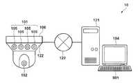
도 1은, 실시형태에 따른 네트워크 카메라 시스템(10)의 모식도다. 네트워크 카메라 시스템(10)은, 감시 카메라 유닛(106)과, 워크스테이션(121)을 구비한다. 감시 카메라 유닛(106)과 워크스테이션(121)은 네트워크(120)를 거쳐 접속되어 있다. 네트워크(120)는 인터넷, 인트라넷, LAN, WAN, WiFi 네트워크, 공중 전화망, 전용선, 배선 또는 그것들의 조합이어도 되고, 무선 네트워크 또는 유선 네트워크이어도 된다. 워크스테이션(121)은 네트워크(120)를 거쳐 감시 카메라 유닛(106)을 관리하기 위한 관리 장치다. 워크스테이션(121)은, 디스플레이(104)(예를 들면, LCD나 유기 EL 패널 등의 표시수단)와, 조작부(901)를 구비한다. 조작부(901)는 유저의 조작을 접수한다. 조작부(901)는, 예를 들면, 키보드, 마우스, 버튼이나 터치패널을 구비해고 되고, 공지의 음성입력을 접수하는 장치이어도 된다. 감시 카메라 유닛은 조작부(901)에 대하여 행해진 지시를 네트워크(120)를 거쳐 수신한다. 이때, 디스플레이(104) 및 조작부(901) 중 적어도 한개를 감시 카메라 유닛(106)에 설치해도 된다.1 is a schematic diagram of a
감시 카메라 유닛(106)은 다안 카메라(101)와 PTZ 카메라(102)를 구비한다. 다안 카메라(101)는 복수(본 실시형태에서는 4개)의 고정 카메라(105)를 포함한다. 다안 카메라(101) 및 PTZ 카메라(102)는 모두 감시 카메라 유닛(106)의 하우징(122)에 설치된다. 다안 카메라(101)에 포함되는 4개의 고정 카메라(105)의 각각은 하우징(122)에 고정된다. 각 고정 카메라(105)는 줌 기능을 갖고 있어도 된다. PTZ 카메라(102)는 하우징(122)에 대하여 가동이 되도록 구성되고, 예를 들면, 공지의 팬/틸트/줌 기능을 갖고 있어도 된다.The
감시 카메라 유닛(106)이 사용될 때, 다안 카메라(101) 및 PTZ 카메라(102)는 실공간 내의 같은 영역(이하, 촬상 영역으로 칭한다)으로 향한다. 다안 카메라(101)는 4개의 고정 카메라(105)로 촬상 영역을 촬상하고, 얻어진 4개의 화상을 합성하고, 합성의 결과 얻어지는 합성 화상, 즉 다안 파노라마 화상을 출력한다. PTZ 카메라(102)는 팬/틸트/줌 기능을 사용해서 촬상 영역을 촬상하고, 얻어진 기준 화상, 즉 PTZ 파노라마 화상을 출력한다.When the
본실시형태에서는, 감시 카메라 유닛(106)을 설치해서 그것의 자세(예를 들면, 방위각으로 표시되는 각도)를 조정할 때, PTZ 파노라마 화상과 다안 파노라마 화상의 차분이 디스플레이(104)에 표시된다. 설치자는 그 표시자를 참조하여, 촬상 영역 내의 관심 대상이 차분으로부터 벗어나도록 감시 카메라 유닛(106)의 방향을 조정할 수 있다.In this embodiment, a difference between the PTZ panoramic image and the multi-view panorama image is displayed on the
도 2는, 본 실시형태에 따른 감시 카메라 유닛(106)의 구성 및 기능을 나타내는 블럭도다. 여기에 나타내는 각 블록은, 하드웨어로, 즉 기계장치나 컴퓨터의 CPU 등의 소자로 실현가능하고, 소프트웨어로, 즉 컴퓨터 프로그램 등에 의해 실현할 수 있지만, 여기에 나타낸 기능 블록은 하드웨어와 소프트웨어의 연계에 의해 실현된다. 따라서, 이들 기능 블록이 하드웨어 및 소프트웨어의 조합에 의해 다양한 방식으로 실현될 수 있다는 사실은, 본 명세서에 해당하는 당업자에 의해 이해될 것이다.2 is a block diagram showing the configuration and functions of the
감시 카메라 유닛(106)은 처리부(125)를 더 구비한다. 감시 카메라 유닛(106)의 각 부재, 즉 다안 카메라(101), PTZ 카메라(102), 처리부(125)는 각각 버스(126)에 접속되고, 버스(126)를 거쳐 서로 통신 가능하게 구성된다. 감시 카메라 유닛(106)은 ROM, RAM, HDD(모두 미도시) 등의 휘발성 또는 불휘발성의 메모리를 구비해도 된다.The
이때, 본실시형태에서는, 처리부(125), 조작 접수부(131), 회전량 산출부(902) 및 다안 파노라마 보완부(601)를 모두 감시 카메라 유닛(106)에 설치할 경우 에 대해 설명하지만, 이것에 한정되지 않는다. 예를 들면, 처리부(125), 조작 접수부(131), 회전량 산출부(902) 및 다안 파노라마 보완부(601) 중 적어도 한개를, 워크스테이션(121)에 설치해도 된다. 처리부(125)가 워크스테이션(121)에 설치되는 경우에는, 감시 카메라 유닛은 카메라로부터의 화상을 네트워크(120)를 거쳐 워크스테이션(121)에 송신하고, 워크스테이션(121)으로부터 차분 정보를 네트워크(120)를 거쳐 수신한다.In this embodiment, the case where the
처리부(125)는, 다안 파노라마 취득부(127)와, PTZ 파노라마 취득부(128)와, 비교부(129)와, 표시 제어부(130)와, 조작 접수부(131)와, 회전량 산출부(902)와, 다안 파노라마 보완부(601)를 구비한다.The
다안 파노라마 취득부(127)는, 촬상 영역으로 향하는 4개의 고정 카메라(105)로부터의 4개의 화상을 합성해서 얻어지는 다안 파노라마 화상을 다안 카메라(101)로부터 버스(126)를 거쳐 취득한다.The multi-view
PTZ 파노라마 취득부(128)는, 촬상 영역으로 향하는 PTZ 카메라(102)로부터의 PTZ 파노라마 화상을 PTZ 카메라(102)로부터 버스(126)를 거쳐 취득한다.The PTZ
비교부(129)는, 다안 파노라마 취득부(127)에 의해 취득된 다안 파노라마 화상과 PTZ 파노라마 취득부(128)에 의해 취득된 PTZ 파노라마 화상을 비교한다. 예를 들면, 비교부(129)는, 다안 파노라마 화상과 PTZ 파노라마 화상의 차분을 특정한다. 촬상 영역은, 다안 카메라(101)의 사각 지대가 되는 사각 영역 및 다안 카메라(101)에 의해 중복해서 촬상되는 중복 영역을 가진다. 비교부(129)에 의해 특정되는 차분은 사각 영역 및 중복 영역에 대응한다.The
이하, 도 3a 내지 도 3c를 참조하여, 다안 파노라마 화상과 PTZ 파노라마 화상의 차이를 설명한다. 도 3a는, 각 고정 카메라 105a 내지 105d의 화각과 피사체 201a 내지 201d의 위치 관계를 나타내는 모식도다. 도 3a는 감시 카메라 유닛(106)을 위에서 본 도면에 대응한다. 각 고정 카메라 105a 내지 105d의 화각에 있는 개별 촬상 영역은 전체의 촬상 영역(210)의 일부다. 이때, 본 실시형태에서는, 설명을 보다 이해하기 쉽게 하기 위해서, 깊이 등은 무시한다. 또한, 본실시형태에서는 4매의 화상을 합성하고 있지만, 합성할 화상 매수는 이것에 한정되지 않고, 예를 들어, 고정 카메라의 수에 따라 결정될 수 있다.Hereinafter, the difference between the multi-view panorama image and the PTZ panorama image will be described with reference to Figs. 3A to 3C. 3A is a schematic diagram showing the positional relationship between the angle of view of each of the fixed
다안 카메라(101)의 4개의 고정 카메라(105)는 원주 방향으로 이격되어서 배치된다. 따라서, 어떤 고정 카메라 105b의 개별 촬상 영역 205b와 인접한 고정 카메라 105c의 개별 촬상 영역 205c 사이에는, 감시 카메라 유닛(106)에 가까운 곳에서 사각 영역(204)이 생기고, 먼 곳에서 중복 영역(203)이 생긴다. 사각 영역(204) 및 중복 영역(203)은 인접하는 개별 촬상 영역 205b 및 205c 사이의 경계(202)를 따라 존재한다.The four fixed
도 3b는, 감시 카메라 유닛(106)에 의해 촬상되는 피사체 201a 내지 201d의 모식도다. 도 3b에서는, 피사체 201a 내지 201d의 일례로서 자동차를 사용한다. 또한, 피사체 201a 내지 201d는 인접하는 개별 촬상 영역 205b, 205c 사이의 경계(202)를 따라 나란하게 배치된다. PTZ 카메라(102)에 의해 촬상 영역(210)을 촬상되는 경우, 도 3b에 도시된 것과 같은 PTZ 파노라마 화상이 얻어진다.Fig. 3B is a schematic diagram of the
도 3c는, 다안 카메라(101)에 의해 촬상 영역(210)을 촬상했을 경우의 다안 파노라마 화상(207)을 도시한 도면이다. 다안 파노라마 화상(207)은, 4개의 고정 카메라 105a 내지 105d에 의해 촬상되는 개별 촬상 영역에 의해 얻어지는 4개의 화상 212a 내지 212d를 합성함으로써 얻어진다. 이들 화상의 합성은 공지의 화상 합성기술을 사용해서 실현될 수 있다. 도 3c에서는, 사각 영역(204) 및 중복 영역(203)의 존재에 의해 피사체 201a 내지 201d의 상 211a 내지 211d에 중복과 결손이 생기고 있다. 피사체 201a는 중복 영역(203)에 위치하므로, 인접하는 고정 카메라 105b, 105c의 개별 촬상 영역 205b, 205c의 양쪽에서 생긴다. 따라서, 다안 파노라마 화상(207)에서는 피사체 201a는 이중 화상(상 211a)으로 표시된다. 피사체 201c, 201d는 사각 영역(204)에 위치하므로, 인접하는 고정 카메라 105b, 105c의 개별 촬상 영역 205b, 205c 모두로부터 피사체의 일부가 결손된다. 이와 달리, 피사체 201c, 201d의 전체가 개별 촬상 영역 205b, 205c 모두로부터 결손된다. 따라서, 다안 파노라마 화상(207)은 피사체 201c, 201d의 일부만 표시하고(상 211c 및 상 211d)가, 그것의 전체를 표시하지 않는다.3C is a view showing the
도 2로 되돌아가, 비교부(129)는, 기준이 되는 PTZ 화상 중에서, 같은 촬상 영역(210)을 나타내는 다안 파노라마 화상(207)에는 포함되지 않는 부분(이하, 결손 부분으로 칭한다) 및 중복하여 나타나는 부분(이하, 중복 부분으로 칭한다)을 특정한다. 전술한 바와 같이, 결손 부분은 사각 영역(204)에 대응하고, 중복 부분은 중복 영역(203)에 대응한다.2, the
비교부(129)는, 소영역 추출부(107)와, 화소값 비교부(108)와, 유지부(109)와, 차분 영역 산출부(110)를 포함한다. 소영역 추출부(107)는, 다안 파노라마 취득부(127)에 의해 취득된 다안 파노라마 화상(207)으로부터 소영역을 추출한다. 소영역 추출부(107)는, PTZ 파노라마 취득부(128)에 의해 취득된 PTZ 파노라마 화상으로부터, 위치적으로 대응하는 소영역을 추출한다. 화소값 비교부(108)는, 추출된 2개의 소영역의 화소값을 비교한다. 유지부(109)는 비교 결과를 유지한다. 다안 파노라마 화상 전체에 대해서 상기한 소영역 비교를 반복하여 행한 후, 차분 영역 산출부(110)는 중복 부분 및 결손 부분을 산출한다.The
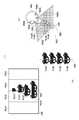
이하, 도 4a 내지 도 4e를 참조하여, 중복 부분 및 결손 부분의 산출 방법을 설명한다. 도 4a는, 다안 카메라(101)에 의해 촬상 영역(210)을 촬상했을 경우의 다안 파노라마 화상(207)을 도시한 도면이다. 도 4a는 도 3c에 대응한다. 도 4b는, PTZ 카메라(102)에 의해 같은 촬상 영역(210)을 촬상했을 경우의 PTZ 파노라마 화상(301)을 도시한 도면이다. 도 4c는, 중복 부분 및 결손 부분의 판정 방법을 나타내는 설명도다. 도 4d는, 중복 부분 및 결손 부분의 판정을 행하는 순서를 나타내는 모식도다. 도 4e는, 중복 부분 및 결손 부분의 생성 방법을 나타내는 설명도다.Hereinafter, a method of calculating overlapping portions and defective portions will be described with reference to Figs. 4A to 4E. Fig. Fig. 4A is a diagram showing a
비교부(129)는, 소정의 소영역(401)마다 다안 파노라마 화상(207)과 PTZ 파노라마 화상(301)의 비교를 행한다. 비교부(129)는, 소영역(401)의 화소값의 차분이 임계값 이상인 경우에는 중복 또는 결손이 발생하였다고 판정하고, 화소값의 차분이 임계값보다 작은 경우에는 중복 및 결손이 발생하지 않았다고 판정한다. 예를 들면, 도 4c에 나타낸 것과 같이, 비교부(129)는, 소영역 401-1에서 화소값의 비교를 행하고, 화소값의 차분이 임계값보다 작기 때문에, 중복 및 결손이 발생하지 않았다고 판정한다. 또한, 비교부(129)는, 소영역 401-N1에서 비교를 행하고, 화소값의 차분이 임계값 이상이 되기 때문에, 중복 또는 결손이 발생하였다고 판정한다. 이때, 화소값의 차분은, 소영역에 포함되는 화소들의 화소값의 평균 차이이거나, 소영역에 있어서의 화소값이 일치하는(또는 일치하지 않는) 화소의 수 또는 비율이어도 된다.The comparing
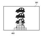
중복/결손의 판정은, 도 4d에 나타낸 것과 같이 소영역 401을 이동함으로써 순서대로 행해진다. 소영역 401의 초기 위치가 각 화상의 좌측 밑이고(초기 위치에 있는 소영역을 소영역 401-1로 나타낸다), 소영역 401-1의 비교가 완료한 후 비교 처리는 우측에 인접하는 소영역 401-2로 이동한다. 그리고, 우측 단부의 소영역 401-N2에 도달한 후, 비교 처리는 그 위의 소영역 401-N3으로 이동한 후, 마찬가지로 처리가 계속될 때 좌측 방향으로 이동한다. 좌측 위의 소영역 401-N4 혹은 우측 위의 소영역 401-N5에 도달하면, 비교부(129)는 판정 처리를 종료한다. 모든 소영역에 대해 판정 처리가 종료하면, 차분 영역 산출부(110)는, 도 4e에 나타낸 것과 같이 판정 결과를 합성함으로써 중복 부분 및 결손 부분을 산출한다. 도 4e의 예에서는, 차분 영역 산출부(110)는, PTZ 파노라마 화상(301)에서 결손 부분(402)을 산출하고 있다.The determination of duplication / deletion is made in order by moving the
도 5는, 비교부(129)에 있어서의 일련의 처리의 흐름을 나타내는 흐름도다. 우선, 스텝 S505에서, 비교부(129)는, 다안 파노라마 화상(207)의 소영역(401)과 PTZ 파노라마 화상(301)의 소영역(401)을 추출해서 비교한다. 스텝 S506에서, 비교부(129)는, 화소값의 차분과 임계값의 대소관계를 판정한다. 차분이 임계값 이상인 경우에는, 스텝 S507에서, 비교부(129)는 해당 소영역(401)에 중복/결손이 있다고 판정하고, 이 소영역(401)의 위치와 판정 결과를 대응시켜 유지부(109)에 격납한다. 판정 결과는, 예를 들면, 중복/결손의 유무를 나타내는 플래그로 표현되어도 된다. 차분이 임계값보다 작은 경우에는, 스텝 S508에서, 비교부(129)는 해당 소영역(401)에 중복/결손은 없다고 판정하고, 이 소영역(401)의 위치와 판정 결과를 대응시켜 유지부(109)에 격납한다. 그리고, 스텝 S509에서, 비교부(129)는 미처리의 소영역(401)이 없는지 판정한다. 미처리의 소영역(401)이 있는 경우에는, 스텝 S511에서, 비교부(129)는 다음의 소영역(401)으로 이동하고, 처리는 스텝 S505로 되돌아간다. 스텝 S509에서 미처리의 소영역(401)이 없다고 판정된 경우에는, 스텝 S510에서, 비교부(129)는 각 소영역(401)의 판정 결과를 유지부(109)로부터 판독하여, 중복 부분 및 결손 부분을 산출한다.5 is a flow chart showing the flow of a series of processing in the
도 2로 되돌아가, 표시 제어부(130)는 비교부(129)에 의해 얻어진 비교 결과를 출력하는 출력부로서 기능한다. 표시 제어부(130)는, 비교부(129)에 의해 특정된 차분을 나타내는 차분 표시자와 함께 PTZ 파노라마 화상(301)을, 네트워크(120)를 거쳐 디스플레이(104)에 표시시킨다. 차분 표시자는, 차분 영역 산출부(110)에 의해 산출된 결손 부분(402)을 나타내는 결손 표시자와, 차분 영역 산출부(110)에 의해 산출된 중복 부분을 나타내는 중복 표시자를 포함한다.Returning to Fig. 2, the
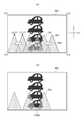
도 6a는, 디스플레이(104)에 표시된 중복 표시자(510)를 수반하는 PTZ 파노라마 화상(301)을 도시한 도면이다. 도 6b는, 디스플레이(104)에 표시된 결손 표시자(511)를 수반하는 PTZ 파노라마 화상(301)을 도시한 도면이다. PTZ 파노라마 화상(301)은 다안 파노라마 화상(207)과 달리, 중복이나 결손이 없이 피사체(201)를 표시할 수 있다. 이 때문에, PTZ 파노라마 화상(301)에 중복 표시자(510)와 결손 표시자(511)를 중첩함으로써, 피사체(201)와 중복 영역(203) 또는 사각 영역(204)의 위치 관계를 인식할 수 있다.6A is a diagram showing a
도 2로 되돌아가, 조작 접수부(131)는, 유저로부터 조작부(901)에 대한 중복 표시자(510) 또는 결손 표시자(511)를 움직이기 위한 지시를, 조작부(901)로부터 네트워크(120)를 거쳐 접수한다. 표시 제어부(130)는, 디스플레이(104)에 표시되어 있는 PTZ 파노라마 화상(301)(기준 화상) 위에서, 접수된 지시에 따라, 중복 표시자(510) 또는 결손 표시자(511)를 움직인다. 유저는, 표시된 중복 표시자(510) 또는 결손 표시자(511)를, 조작부(901)를 사용해서 PTZ 파노라마 화상(301) 위에서 이동시킬 수 있다. 회전량 산출부(902)는, 중복 표시자(510) 또는 결손 표시자(511)의 이동을 수반하는 하우징(122)의 움직임 량을 산출한다. 움직임 량은, 예를 들면, 실제로 중복 영역(203) 또는 사각 영역(204)을 이동시키기 위해서 필요한, 하우징(122)의 회전 각도이다.2, the
이하, 도 7a 및 도 7b를 참조하여, 결손 표시자(511)의 이동에 대해 설명한다. 일례로서, 결손 표시자(511)를 표시하는 PTZ 파노라마 화상(301) 위에서, 결손 표시자(511)가 화살표(710)의 방향(좌측 방향)으로 이동하는 경우를 생각한다. 도 7a는, 이동전의 결손 표시자(511)와 이동후의 결손 표시자(711)를 도시한 도면이다. 도 7a에 있어서, 이동전의 결손 표시자(511)는 실선의 윤곽을 갖고, 이동후의 결손 표시자(711)는 파선의 윤곽을 갖지만, 실제의 표시 형태는 이것에 한정되지 않는다.Hereinafter, the movement of the
도 7b는, 이동후의 결손 표시자(711)를 수반하는 PTZ 파노라마 화상(301)을 도시한 도면이다. 결손 표시자는 PTZ 파노라마 화상(301) 위에서 이동하지만, 이 시점에서는 대응하는 사각 영역(204)의 위치는 아직 이동하지 않았다. 도 7b는 감시 카메라 유닛(106)을 회전시키는 것에 관한 시뮬레이션의 결과를 나타내고 있다. 이 때문에, 표시 제어부(130)는 이동후의 결손 표시자(711)를 이동전의 결손 표시자(511)와는 다른 태양으로 표시해도 된다. 예를 들면, 도 7b의 예에서는, 이동후의 결손 표시자(711)는 파선의 윤곽을 갖는 것으로 표시되어 있다.FIG. 7B is a diagram showing a
디스플레이(104)에 표시되어 있는 PTZ 파노라마 화상(301) 위에서, 유저로부터의 지시에 따라, 결손 표시자(511)가 움직이면, 움직이기 전에 결손 표시자(511)에 의해 숨겨져 있었던 PTZ 파노라마 화상(301)의 부분이 나타난다. 예를 들면, 도 7a의 상태에서는, 감시 카메라 유닛(106)에 가장 가까운 피사체 201d의 상 712d의 창 부분은 결손 표시자(511)에 의해 숨겨져 있다. 결손 표시자(511)를 움직인 후의 도 7b의 상태에서는, 이 창 부분이 보인다. 이렇게, 결손 표시자의 이동에 의해 그이 결손 표시자 아래에 숨겨져 있었던 상이 나타나므로, 유저는 결손 표시자를 어느 정도 또는 어떻게 움직이면 관심 대상이 보이게 되는 것인지를 용이하게 알 수 있다.If the
이하, 도 7a를 참조하여, 회전량 산출부(902)에 있어서의 회전 각도의 산출 방법에 대해 설명한다. 일례로서, 결손 표시자(511)가 도 7a에 나타낸 것과 같이 이동하는 경우를 생각한다. 도 7a에서는, PTZ 파노라마 화상(301)에 다음과 같이 좌표를 할당되는데, 즉 좌측 밑에 (0, 0)를, 우측 밑에 (a, 0)를, 좌측 위에 (0, b)를, 우측 위에 (a, b)를, 이동전의 결손 표시자(511)의 정점에 (x1, y1)를, 이동후의 결손 표시자(711)의 정점에 (x2, y1)를 할당한다. 이때, 좌표는 중복 부분 및 결손 부분의 산출시에 사용한 소영역(401)과 대응시켜 할당하고 있다. 도 7a의 가로 방향을 x방향, 세로 방향을 y방향으로 한다. x 방향의 이동량에 대한 감시 카메라 유닛(106)(또는 그것의 하우징(122))의 회전 각도는, 이하에 나타내는 식 (1)에서 산출된다. 여기에서, α는 PTZ 파노라마 화상(301)에 대응하는 각도 범위다. 예를 들면, 전방위의 PTZ 파노라마 화상(301)을 생성하는 경우에는, α=360도이다.Hereinafter, with reference to Fig. 7A, a calculation method of the rotation angle in the rotation
이동에 대한 회전 각도=(x2-x1)x(α÷a)…(1)Rotation angle for movement = (x2-x1) x (? / A)... (One)
도 8은, 회전량 산출부(902)에 있어서의 일련의 처리의 흐름을 나타내는 흐름도다. 우선, 스텝 S801에서, 회전량 산출부(902)는 PTZ 파노라마 화상(301)에 대응하는 각도 범위(α)를 취득한다. 예를 들면, 전방위의 PTZ 파노라마 화상(301)을 생성하고 있는 경우에는, 각도 범위는 0도 내지 360도이다. 다음에, 스텝 S802에서, 회전량 산출부(902)는 PTZ 파노라마 화상(301)의 끝의 좌표 (a, b)와, 이동전의 결손 표시자(511)의 정점의 좌표 (x1, y1)를 취득한다. 좌표 취득후, 스텝 S803에서, 유저는 조작부(901)를 사용해서 결손 표시자를 이동시킨다. 스텝 S804에서, 회전량 산출부(902)는 이동후의 결손 표시자(711)의 정점의 좌표 (x2, y1)를 산출한다. 스텝 S805에서, 회전량 산출부(902)는 식(1)을 사용하여, 결손 표시자의 이동에 필요한 회전 각도를 산출한다. 스텝 S806에서, 회전량 산출부(902)는, 산출된 회전 각도를 유저에게 통지한다. 통지는, 표시 제어부(130)를 거쳐 회전 각도를 디스플레이(104)에 표시시킴으로써 행해지거나, 회전 각도를 표시하는 음성을 합성해서 출력함으로써 행해져도 된다.Fig. 8 is a flowchart showing the flow of a series of processing in the rotation
도 2로 되돌아가, 다안 파노라마 보완부(601)는, 비교부(129)로부터의 비교 결과에 근거하여 다안 파노라마 화상(207)을 보완한다. 다안 파노라마 보완부(601)는, 비교부(129)에서 산출된 결손 부분(402)에 따라 다안 파노라마 화상(207)을 보완한다. 다안 파노라마 화상(207)은 PTZ 파노라마 화상(301)과 다른 결손을 갖기 때문에, 결손 부분(402)을 보충하도록 다안 파노라마 화상(207)을 조정함으로써, 위화감을 경감할 수 있다. 표시 제어부(130)는, 다안 파노라마 보완부(601)에 의해 보완된 다안 파노라마 화상을 디스플레이(104)에 표시시킨다.Returning to Fig. 2, the multi-view
도 9a는, 디스플레이(104)에 표시된 중복 표시자(911)를 수반하는 다안 파노라마 화상(207)을 도시한 도면이다. 중복 표시자(911)는, 차분 영역 산출부(110)에 의해 산출된 중복 부분을 나타낸다. 도 9b는, 디스플레이(104)에 표시된 결손 표시자(912)를 수반하는 보완 다안 화상(910)을 도시한 도면이다. 결손 표시자(912)는, 차분 영역 산출부(110)에 의해 산출된 결손 부분(402)을 나타낸다. 다안 파노라마 보완부(601)는, 다안 파노라마 화상(207)에 결손 표시자(912)를 삽임함으로써 보완 다안 화상(910)을 생성한다.9A is a diagram showing a
이상의 구성을 갖는 감시 카메라 유닛(106)의 동작을 설명한다.The operation of the
도 10은, 감시 카메라 유닛(106)에 있어서의 일련의 처리의 흐름을 나타내는 흐름도다. 우선, 스텝 S171에서, 감시 카메라 유닛(106)은 다안 카메라(101)를 사용해서 다안 파노라마 화상(207)을 생성한다. 스텝 S172에서, 감시 카메라 유닛(106)은 PTZ 카메라(102)의 팬/틸트/줌 기능을 사용하여, 예를 들면, PTZ 카메라(102)를 회전시킴으로써, 광역을 스캔하여, PTZ 파노라마 화상(301)을 생성한다. 스텝 S173에서, 감시 카메라 유닛(106)은 다안 파노라마 화상(207)과 PTZ 파노라마 화상(301)을 비교하여, 중복 부분 및 결손 부분을 산출한다. 산출후, 스텝 S174에서, 감시 카메라 유닛(106)은, 산출한 중복 부분 및 결손 부분에 대응하는 중복 표시자 및 결손 표시자를 PTZ 파노라마 화상(301)에 중첩시켜, 화상을 디스플레이(104)에 표시시킨다. 스텝 S175에서, 감시 카메라 유닛(106)은, 산출된 결손 부분에 근거하여 다안 파노라마 화상(207)을 보완한다. 스텝 S176에서, 감시 카메라 유닛(106)은 보완후의 다안 파노라마 화상(보완 다안 화상)을 디스플레이(104)에 표시시킨다.10 is a flowchart showing the flow of a series of processes in the
도 11은, 설치자가 감시 카메라 유닛(106)의 자세를 조정하는 절차를 나타내는 흐름도다. 스텝 S180에서, 설치자는 감시 카메라 유닛(106)을 원하는 위치에 설치한다. 스텝 S181에서, 설치자는, 워크스테이션(121)의 디스플레이(104)를 사용하여, 촬상 영역(210)에 관심 대상이 포함되는 방법을 확인한다. 스텝 S182에서, 설치자는, 관심 대상이 차분 표시자들(예를 들면, 중복 표시자나 결손 표시자)에 의해 숨겨져 있는지 아닌지를 판정한다. 숨겨져 있지 않은 경우, 설치는 완료한다. 숨겨져 있을 경우, 스텝 S183에서, 설치자는, 디스플레이(104)에 표시되는 PTZ 파노라마 화상(301)에서 관심 대상이 나타나도록 차분 표시자를 이동시킨다. 예를 들면, 설치자는 조작부(901)를 조작함으로써, 관심 대상이 차분 표시로부터 벗어나도록 차분 표시자를 이동시킨다. 스텝 S184에서, 설치자는, 감시 카메라 유닛(106) 또는 워크 스테이션(121)으로부터, 이동량에 대응하는 회전 각도의 통지를 받는다. 스텝 S185에서, 설치자는, 통지된 회전 각도가 실현되도록 감시 카메라 유닛(106) 전체를 회전시킨다.11 is a flowchart showing a procedure in which the installer adjusts the posture of the
본 실시형태의 감시 카메라 유닛(106)에 따르면, 다안 파노라마 화상(207)의 중복 부분과 결손 부분의 위치를 파악하기 쉬워지므로, 피사체(201)와 중복 영역(203) 또는 사각 영역(204)의 위치 관계를 용이하게 파악할 수 있다. 이에 따라, 이 위치 관계를 고려하여 감시 카메라 유닛(106)의 설치가 보다 용이해진다. 예를 들면, 감시 카메라 유닛(106)의 설치시에 주시하고 싶은 피사체가 있을 경우, 그 피사체로부터 중복 영역(203) 및 사각 영역(204)이 벗어나도록 감시 카메라 유닛(106)을 설치할 수 있다.The
이상에서, 본 실시형태에 따른 감시 카메라 유닛(106)의 구성과 동작에 대해 설명했다. 본 실시형태는 예시이며, 그 각 구성요소와 각 처리단계의 조합에 의해 다양한 변형예가 가능하고, 그러한 변형예도 본 발명의 범위에 속하는 것은 당업자에게 이해되는 점이다.The configuration and operation of the
본 실시형태에서는, 결손 표시자(511)를 x방향으로 평행 이동시킬 경우에 대해 설명했지만, 이것에 한정되지 않는다. 다른 태양의 표시의 이동도 가능하다. 예를 들면, 결손 표시자(511)를 y방향으로 이동시켜도 된다.In the present embodiment, the case where the
본 실시형태에서는, 기준 화상을 생성하는 촬상부로서 PTZ 카메라(102)를 사용할 경우에 대해 설명했지만, 이것에 한정되지 않는다. 예를 들면, 어안 렌즈를 구비한 카메라(어안 카메라) 등과 같이 고정 카메라(105)보다도 넓은 화각을 가지는 카메라를 사용할 수 있다.In the present embodiment, the case where the
기타 실시형태Other embodiments
본 발명의 실시형태는, 본 발명의 전술한 실시형태(들)의 1개 이상의 기능을 수행하기 위해 기억매체('비일시적인 컴퓨터 판독가능한 기억매체'로서 더 상세히 언급해도 된다)에 기록된 컴퓨터 실행가능한 명령(예를 들어, 1개 이상의 프로그램)을 판독하여 실행하거나 및/또는 전술한 실시예(들)의 1개 이상의 기능을 수행하는 1개 이상의 회로(예를 들어, 주문형 반도체 회로(ASIC)를 포함하는 시스템 또는 장치의 컴퓨터나, 예를 들면, 전술한 실시형태(들)의 1개 이상의 기능을 수행하기 위해 기억매체로부터 컴퓨터 실행가능한 명령을 판독하여 실행함으로써, 시스템 또는 장치의 컴퓨터에 의해 수행되는 방법에 의해 구현될 수도 있다. 컴퓨터는, 1개 이상의 중앙처리장치(CPU), 마이크로 처리장치(MPU) 또는 기타 회로를 구비하고, 별개의 컴퓨터들의 네트워크 또는 별개의 컴퓨터 프로세서들을 구비해도 된다. 컴퓨터 실행가능한 명령은, 예를 들어, 기억매체의 네트워크로부터 컴퓨터로 주어져도 된다. 기록매체는, 예를 들면, 1개 이상의 하드디스크, 랜덤 액세스 메모리(RAM), 판독 전용 메모리(ROM), 분산 컴퓨팅 시스템의 스토리지, 광 디스크(콤팩트 디스크(CD), 디지털 다기능 디스크(DVD), 또는 블루레이 디스크(BD)TM 등), 플래시 메모리소자, 메모리 카드 등을 구비해도 된다.Embodiments of the present invention may be practiced using computer executable programs (e.g., computer readable instructions) recorded on a storage medium (which may be referred to as " non-volatile computer readable storage medium ") for performing one or more functions of the above- (E.g., an application specific integrated circuit (ASIC)) that reads and executes possible instructions (e.g., one or more programs) and / or performs one or more functions of the above- For example, by reading and executing computer-executable instructions from a storage medium to perform one or more functions of the above-described embodiment (s), such as by a computer of the system or apparatus The computer may comprise one or more central processing units (CPUs), microprocessors (MPUs), or other circuitry, and may be implemented in a network of discrete computers The computer-executable instructions may, for example, be presented to a computer from a network of storage media. The storage medium may comprise, for example, one or more hard disks, a random access memory RAM), read only memory (ROM), a distributed computing system storage, an optical disk (a compact disc (CD), digital versatile disk (DVD), or Blu-ray disc (BD),TM, etc.), flash memory device, a memory card, etc. .
본 발명은, 상기한 실시형태의 1개 이상의 기능을 실현하는 프로그램을, 네트워크 또는 기억매체를 개입하여 시스템 혹은 장치에 공급하고, 그 시스템 혹은 장치의 컴퓨터에 있어서 1개 이상의 프로세서가 프로그램을 읽어 실행하는 처리에서도 실행가능하다. 또한, 1개 이상의 기능을 실현하는 회로(예를 들어, ASIC)에 의해서도 실행가능하다.The present invention provides a program or a program for realizing one or more functions of the above-described embodiments to a system or an apparatus via a network or a storage medium, and in the computer of the system or apparatus, . It may also be implemented by a circuit (for example, an ASIC) that realizes one or more functions.
예시적인 실시형태들을 참조하여 본 발명을 설명하였지만, 본 발명이 이러한 실시형태에 한정되지 않는다는 것은 자명하다. 이하의 청구범위의 보호범위는 가장 넓게 해석되어 모든 변형, 동등물 구조 및 기능을 포괄하여야 한다.While the present invention has been described with reference to exemplary embodiments, it is to be understood that the invention is not limited to those embodiments. The scope of the following claims is to be accorded the broadest interpretation so as to encompass all such modifications, equivalent structures and functions.
Claims (12)
Translated fromKorean상기 소정의 영역으로 향하는 제2 촬상부로부터의 기준 화상을 취득하도록 구성된 제2 취득부와,
상기 합성 화상과 상기 기준 화상을 비교하도록 구성된 비교부와,
상기 비교부로부터의 비교 결과를 출력하도록 구성된 출력부를 구비한 화상 처리장치.
A first acquisition unit configured to acquire a composite image obtained by synthesizing a plurality of images from a plurality of first imaging units facing a predetermined area,
A second acquiring unit configured to acquire a reference image from a second imaging unit facing the predetermined area,
A comparison unit configured to compare the synthesized image and the reference image,
And an output unit configured to output a comparison result from the comparison unit.
상기 비교부는 상기 합성 화상과 상기 기준 화상의 차분을 특정하는 화상 처리장치.
The method according to claim 1,
Wherein the comparison unit specifies the difference between the composite image and the reference image.
상기 출력부는 상기 차분을 나타내는 표시자와 함께 상기 기준 화상을 표시부에 표시하는 화상 처리장치.
3. The method of claim 2,
And the output unit displays the reference image on a display unit together with an indicator indicating the difference.
상기 차분을 나타내는 상기 표시자를 움직이기 위한 지시를 접수하도록 구성된 접수부를 더 구비하고,
상기 출력부는, 상기 표시부에 표시된 상기 기준 화상 위에, 상기 지시에 따라 상기 차분을 나타내는 상기 표시자를 움직이는 화상 처리장치.
The method of claim 3,
Further comprising a reception unit configured to receive an instruction to move the indicator indicating the difference,
Wherein the output section moves the indicator indicating the difference on the reference image displayed on the display section in accordance with the instruction.
상기 차분을 나타내는 상기 표시자의 이동을 수반하는 상기 화상 처리장치의 하우징의 움직임 량을 산출하도록 구성된 산출부를 더 구비한 화상 처리장치.
5. The method of claim 4,
And a calculation unit configured to calculate a motion amount of the housing of the image processing apparatus accompanied by the movement of the indicator indicating the difference.
상기 표시부에 표시된 상기 기준 화상 위에, 상기 지시에 따라 상기 차분을 나타내는 상기 표시자가 움직이면, 움직이기 전에 상기 차분을 나타내는 상기 표시자에 의해 숨겨져 있었던 상기 기준 화상의 부분이 나타나는 화상 처리장치.
5. The method of claim 4,
When the indicator indicating the difference moves on the reference image displayed on the display unit according to the instruction, the portion of the reference image hidden by the indicator indicating the difference appears before the movement.
상기 비교부로부터의 비교 결과에 근거하여 상기 합성 화상을 보완하도록 구성된 보완부를 더 구비하고,
상기 출력부는 보완된 상기 합성 화상을 표시부에 표시하는 화상 처리장치.
The method according to claim 1,
And a complementary unit configured to supplement the synthesized image based on the comparison result from the comparison unit,
And the output unit displays the complemented composite image on a display unit.
상기 소정의 영역은, 상기 복수의 제1 촬상부의 사각 영역 및 상기 복수의 제1 촬상부에 의해 중복해서 촬상되는 영역 중에서 적어도 한 개의 영역을 갖고, 상기 비교부로부터의 비교 결과는 상기 적어도 한개의 영역에 대응하는 화상 처리장치.
The method according to claim 1,
Wherein the predetermined area has at least one area out of a rectangular area of the plurality of first imaging units and a region that is overlapped by the plurality of first imaging units and the comparison result from the comparison unit indicates the at least one Area corresponding to the area.
상기 제2 촬상부는, 상기 복수의 제1 촬상부가 설치되는 하우징에 설치되어 있는 화상 처리장치.
The method according to claim 1,
Wherein the second imaging unit is provided in a housing in which the plurality of first imaging units are provided.
상기 복수의 제1 촬상부의 각각은 상기 하우징에 고정되고, 상기 제2 촬상부는 상기 하우징에 대하여 가동이 되도록 구성되는 화상 처리장치.
10. The method of claim 9,
Wherein each of the plurality of first imaging units is fixed to the housing, and the second imaging unit is configured to be movable with respect to the housing.
복수의 제1 촬상부와 제2 촬상부를 구비한 촬상장치를 설치하는 단계와,
제2 촬상부로부터 얻어지고, 기준 화상과 상기 복수의 제1 촬상부로부터의 복수의 화상을 합성해서 얻어지는 합성 화상의 차분을 나타내는 표시자와 함께 표시부에 표시되는 상기 기준 화상 위에서, 관심 대상이 상기 차분으로부터 벗어나도록 상기 표시자를 이동시키는 단계와,
이동량에 따라 상기 촬상장치의 자세를 조정하는 단계를 포함하는 방법을 실행시키는 컴퓨터 프로그램을 기억한 비일시적인 컴퓨터 판독가능한 기억매체.
On the computer,
Installing an image pickup apparatus having a plurality of first image pickup units and a second image pickup unit;
On the reference image displayed on the display unit together with the indicator obtained from the second image pickup unit and indicating the difference between the reference image and the plurality of images obtained from the plurality of first image pickup units, Moving the indicator to deviate from the difference;
And adjusting the posture of the imaging device in accordance with the amount of movement of the imaging device.
제2 촬상부로부터 얻어지고, 기준 화상과 상기 복수의 제1 촬상부로부터의 복수의 화상을 합성해서 얻어지는 합성 화상의 차분을 나타내는 표시자와 함께 표시부에 표시되는 상기 기준 화상 위에서, 관심 대상이 상기 차분으로부터 벗어나도록 상기 표시자를 이동시키는 단계와,
이동량에 따라 상기 촬상장치의 자세를 조정하는 단계를 포함하는 방법.Installing an image pickup apparatus having a plurality of first image pickup units and a second image pickup unit;
On the reference image displayed on the display unit together with the indicator obtained from the second image pickup unit and indicating the difference between the reference image and the plurality of images obtained from the plurality of first image pickup units, Moving the indicator to deviate from the difference;
And adjusting the posture of the imaging device in accordance with the amount of movement.
Applications Claiming Priority (2)
| Application Number | Priority Date | Filing Date | Title |
|---|---|---|---|
| JPJP-P-2017-173220 | 2017-09-08 | ||
| JP2017173220AJP6956574B2 (en) | 2017-09-08 | 2017-09-08 | Image processing equipment, programs and methods |
Publications (2)
| Publication Number | Publication Date |
|---|---|
| KR20190028305Atrue KR20190028305A (en) | 2019-03-18 |
| KR102278200B1 KR102278200B1 (en) | 2021-07-16 |
Family
ID=63371473
Family Applications (1)
| Application Number | Title | Priority Date | Filing Date |
|---|---|---|---|
| KR1020180104352AActiveKR102278200B1 (en) | 2017-09-08 | 2018-09-03 | Image processing apparatus, medium, and method |
Country Status (5)
| Country | Link |
|---|---|
| US (1) | US10861188B2 (en) |
| EP (1) | EP3454548B1 (en) |
| JP (1) | JP6956574B2 (en) |
| KR (1) | KR102278200B1 (en) |
| CN (1) | CN109474792B (en) |
Families Citing this family (6)
| Publication number | Priority date | Publication date | Assignee | Title |
|---|---|---|---|---|
| CN111208148A (en)* | 2020-02-21 | 2020-05-29 | 凌云光技术集团有限责任公司 | Dig hole screen light leak defect detecting system |
| JP7632861B2 (en)* | 2020-07-08 | 2025-02-19 | i-PRO株式会社 | Surveillance camera system and surveillance camera setting method |
| JP7695109B2 (en)* | 2021-05-28 | 2025-06-18 | キヤノン株式会社 | Information processing device, information processing system, information processing method, and program |
| US12249042B2 (en)* | 2022-03-23 | 2025-03-11 | Lenovo (Singapore) Pte. Ltd | Method and system to combine video feeds into panoramic video |
| JP2023155822A (en)* | 2022-04-11 | 2023-10-23 | キヤノン株式会社 | Information processing system, moving body, information processing method, and computer program |
| EP4270940B1 (en)* | 2022-04-26 | 2024-10-30 | Axis AB | Ptz masking control |
Citations (5)
| Publication number | Priority date | Publication date | Assignee | Title |
|---|---|---|---|---|
| US20050099500A1 (en)* | 2003-11-11 | 2005-05-12 | Canon Kabushiki Kaisha | Image processing apparatus, network camera system, image processing method and program |
| EP1579399B1 (en)* | 2002-11-07 | 2007-07-25 | WQS Ltd. | Surveillance device |
| US20120274776A1 (en)* | 2011-04-29 | 2012-11-01 | Canon Kabushiki Kaisha | Fault tolerant background modelling |
| EP2607951A1 (en)* | 2011-12-19 | 2013-06-26 | Axis AB | Method for setting up a monitoring camera |
| US20160210078A1 (en)* | 2015-01-20 | 2016-07-21 | Ultrata Llc | Universal single level object memory address space |
Family Cites Families (14)
| Publication number | Priority date | Publication date | Assignee | Title |
|---|---|---|---|---|
| US7940299B2 (en)* | 2001-08-09 | 2011-05-10 | Technest Holdings, Inc. | Method and apparatus for an omni-directional video surveillance system |
| JP4568009B2 (en)* | 2003-04-22 | 2010-10-27 | パナソニック株式会社 | Monitoring device with camera cooperation |
| JP2008252863A (en)* | 2007-03-02 | 2008-10-16 | Fujifilm Corp | Imaging system, imaging method, and program |
| JP5245185B2 (en)* | 2009-03-31 | 2013-07-24 | サクサ株式会社 | Tobacco monitoring device |
| CN102577347B (en) | 2009-06-29 | 2015-09-23 | 博世安防系统有限公司 | All-around intelligent makes an inspection tour the spherical surveillance camera system and method with Situation Awareness automatically |
| US9007432B2 (en)* | 2010-12-16 | 2015-04-14 | The Massachusetts Institute Of Technology | Imaging systems and methods for immersive surveillance |
| CN102857739B (en) | 2012-08-20 | 2015-09-09 | 上海光亮光电科技有限公司 | Distributed overall view monitoring system and method thereof |
| JP2014175706A (en)* | 2013-03-06 | 2014-09-22 | Sumitomo Electric Ind Ltd | Monitor device, monitor method, and imaging unit arrangement method |
| CN103338343A (en) | 2013-05-29 | 2013-10-02 | 山西绿色光电产业科学技术研究院(有限公司) | Multi-image seamless splicing method and apparatus taking panoramic image as reference |
| WO2014199786A1 (en) | 2013-06-11 | 2014-12-18 | シャープ株式会社 | Imaging system |
| JP2015204512A (en)* | 2014-04-14 | 2015-11-16 | パナソニックIpマネジメント株式会社 | Information processing apparatus, information processing method, camera, reception device, and reception method |
| EP3133819A1 (en) | 2014-04-14 | 2017-02-22 | Panasonic Intellectual Property Management Co., Ltd. | Image delivery method, image reception method, server, terminal apparatus, and image delivery system |
| CN104483983B (en) | 2014-11-24 | 2016-12-07 | 成都新舟锐视科技有限公司 | A kind of double cloud platform control methods of multi-cam real-time linkage |
| TWI526992B (en)* | 2015-01-21 | 2016-03-21 | 國立清華大學 | Method for optimizing occlusion in augmented reality based on depth camera |
- 2017
- 2017-09-08JPJP2017173220Apatent/JP6956574B2/enactiveActive
- 2018
- 2018-08-08EPEP18187947.9Apatent/EP3454548B1/enactiveActive
- 2018-08-30USUS16/117,565patent/US10861188B2/enactiveActive
- 2018-09-03KRKR1020180104352Apatent/KR102278200B1/enactiveActive
- 2018-09-07CNCN201811042874.8Apatent/CN109474792B/enactiveActive
Patent Citations (5)
| Publication number | Priority date | Publication date | Assignee | Title |
|---|---|---|---|---|
| EP1579399B1 (en)* | 2002-11-07 | 2007-07-25 | WQS Ltd. | Surveillance device |
| US20050099500A1 (en)* | 2003-11-11 | 2005-05-12 | Canon Kabushiki Kaisha | Image processing apparatus, network camera system, image processing method and program |
| US20120274776A1 (en)* | 2011-04-29 | 2012-11-01 | Canon Kabushiki Kaisha | Fault tolerant background modelling |
| EP2607951A1 (en)* | 2011-12-19 | 2013-06-26 | Axis AB | Method for setting up a monitoring camera |
| US20160210078A1 (en)* | 2015-01-20 | 2016-07-21 | Ultrata Llc | Universal single level object memory address space |
Also Published As
| Publication number | Publication date |
|---|---|
| KR102278200B1 (en) | 2021-07-16 |
| US20190080477A1 (en) | 2019-03-14 |
| JP2019049824A (en) | 2019-03-28 |
| CN109474792B (en) | 2021-05-04 |
| CN109474792A (en) | 2019-03-15 |
| EP3454548B1 (en) | 2021-06-30 |
| EP3454548A1 (en) | 2019-03-13 |
| US10861188B2 (en) | 2020-12-08 |
| JP6956574B2 (en) | 2021-11-02 |
Similar Documents
| Publication | Publication Date | Title |
|---|---|---|
| KR20190028305A (en) | Image processing apparatus, medium, and method | |
| JP5906028B2 (en) | Image processing apparatus and image processing method | |
| US9369612B2 (en) | Image fusion system and method | |
| JP4912117B2 (en) | Imaging device with tracking function | |
| EP3588456A1 (en) | Image processing apparatus, image processing method, and program | |
| JP5613041B2 (en) | Camera device, image processing system, and image processing method | |
| WO2018204279A1 (en) | Automated matrix photo framing using range camera input | |
| US20120293633A1 (en) | Stereo camera | |
| JP2015210702A (en) | Image processing apparatus and image processing method | |
| US9766057B1 (en) | Characterization of a scene with structured light | |
| CN105577983B (en) | Apparatus and method for detecting motion masks | |
| JP2021185681A5 (en) | Imaging systems, imaging devices, video display devices, image processing devices, methods and programs. | |
| US10348963B2 (en) | Super resolution binary imaging and tracking system | |
| US20180343435A1 (en) | Display control apparatus, display control method, and storage medium | |
| US11416978B2 (en) | Image processing apparatus, control method and non-transitory computer-readable recording medium therefor | |
| JP2013218432A (en) | Image processing device, image processing method, program for image processing, and recording medium | |
| JP2016063248A (en) | Image processing apparatus and image processing method | |
| JP6705102B2 (en) | Imaging device installation support device, imaging device installation support method, and video recording/reproducing device | |
| CN106445195A (en) | Method, apparatus and system for detecting position of laser point in screen | |
| JP5727969B2 (en) | Position estimation apparatus, method, and program | |
| JP2018201146A (en) | Image correction apparatus, image correction method, attention point recognition apparatus, attention point recognition method, and abnormality detection system | |
| US11830177B2 (en) | Image processing apparatus, control method and non-transitory computer-readable recording medium therefor | |
| CN109429018B (en) | Image processing device and method | |
| KR101868057B1 (en) | Method for generating panoramic image and apparatus thereof | |
| JP4825479B2 (en) | Monitoring system and monitoring method |
Legal Events
| Date | Code | Title | Description |
|---|---|---|---|
| PA0109 | Patent application | Patent event code:PA01091R01D Comment text:Patent Application Patent event date:20180903 | |
| PG1501 | Laying open of application | ||
| A201 | Request for examination | ||
| PA0201 | Request for examination | Patent event code:PA02012R01D Patent event date:20200303 Comment text:Request for Examination of Application Patent event code:PA02011R01I Patent event date:20180903 Comment text:Patent Application | |
| E902 | Notification of reason for refusal | ||
| PE0902 | Notice of grounds for rejection | Comment text:Notification of reason for refusal Patent event date:20201110 Patent event code:PE09021S01D | |
| PE0701 | Decision of registration | Patent event code:PE07011S01D Comment text:Decision to Grant Registration Patent event date:20210416 | |
| GRNT | Written decision to grant | ||
| PR0701 | Registration of establishment | Comment text:Registration of Establishment Patent event date:20210712 Patent event code:PR07011E01D | |
| PR1002 | Payment of registration fee | Payment date:20210713 End annual number:3 Start annual number:1 | |
| PG1601 | Publication of registration | ||
| PR1001 | Payment of annual fee | Payment date:20240625 Start annual number:4 End annual number:4 | |
| PR1001 | Payment of annual fee | Payment date:20250630 Start annual number:5 End annual number:5 |