KR20190028165A - Circular anastomosis stampling instrument - Google Patents
Circular anastomosis stampling instrumentDownload PDFInfo
- Publication number
- KR20190028165A KR20190028165AKR1020170115279AKR20170115279AKR20190028165AKR 20190028165 AKR20190028165 AKR 20190028165AKR 1020170115279 AKR1020170115279 AKR 1020170115279AKR 20170115279 AKR20170115279 AKR 20170115279AKR 20190028165 AKR20190028165 AKR 20190028165A
- Authority
- KR
- South Korea
- Prior art keywords
- head
- guide
- driving
- protruding
- anus
- Prior art date
- Legal status (The legal status is an assumption and is not a legal conclusion. Google has not performed a legal analysis and makes no representation as to the accuracy of the status listed.)
- Granted
Links
Images


Classifications
- A—HUMAN NECESSITIES
- A61—MEDICAL OR VETERINARY SCIENCE; HYGIENE
- A61B—DIAGNOSIS; SURGERY; IDENTIFICATION
- A61B17/00—Surgical instruments, devices or methods
- A61B17/11—Surgical instruments, devices or methods for performing anastomosis; Buttons for anastomosis
- A61B17/115—Staplers for performing anastomosis, e.g. in a single operation
- A—HUMAN NECESSITIES
- A61—MEDICAL OR VETERINARY SCIENCE; HYGIENE
- A61B—DIAGNOSIS; SURGERY; IDENTIFICATION
- A61B17/00—Surgical instruments, devices or methods
- A61B17/11—Surgical instruments, devices or methods for performing anastomosis; Buttons for anastomosis
- A61B17/1114—Surgical instruments, devices or methods for performing anastomosis; Buttons for anastomosis of the digestive tract, e.g. bowels or oesophagus
- A—HUMAN NECESSITIES
- A61—MEDICAL OR VETERINARY SCIENCE; HYGIENE
- A61B—DIAGNOSIS; SURGERY; IDENTIFICATION
- A61B17/00—Surgical instruments, devices or methods
- A61B2017/00017—Electrical control of surgical instruments
- A61B2017/00115—Electrical control of surgical instruments with audible or visual output
- A—HUMAN NECESSITIES
- A61—MEDICAL OR VETERINARY SCIENCE; HYGIENE
- A61B—DIAGNOSIS; SURGERY; IDENTIFICATION
- A61B17/00—Surgical instruments, devices or methods
- A61B2017/00367—Details of actuation of instruments, e.g. relations between pushing buttons, or the like, and activation of the tool, working tip, or the like
- A61B2017/00398—Details of actuation of instruments, e.g. relations between pushing buttons, or the like, and activation of the tool, working tip, or the like using powered actuators, e.g. stepper motors, solenoids
Landscapes
- Health & Medical Sciences (AREA)
- Life Sciences & Earth Sciences (AREA)
- Surgery (AREA)
- Heart & Thoracic Surgery (AREA)
- Engineering & Computer Science (AREA)
- Biomedical Technology (AREA)
- Nuclear Medicine, Radiotherapy & Molecular Imaging (AREA)
- Medical Informatics (AREA)
- Molecular Biology (AREA)
- Animal Behavior & Ethology (AREA)
- General Health & Medical Sciences (AREA)
- Public Health (AREA)
- Veterinary Medicine (AREA)
- Physiology (AREA)
- Surgical Instruments (AREA)
Abstract
Translated fromKoreanDescription
Translated fromKorean본 발명은 원형 문합기에 관한 것으로, 더욱 상세하게는 원형 문합기의 체내 삽입을 가이드하는 가이드 부재가 적용되는 원형 문합기에 관한 것이다.BACKGROUND OF THE INVENTION 1. Field of the Invention [0001] The present invention relates to a circular anchor machine, and more particularly, to a circular anchor machine to which a guide member for guiding insertion of a circular anchor machine is applied.
문합(anastomosis)이란 식도, 위, 대장, 소장과 같은 인체의 장질환과 관련된 절단수술 후 장기의 절단된 부분을 접합하는 것으로, 문합수술은 인체에서 식도암에 의한 식도 부분제거수술 후의 식도재건, 위암에 의한 위 제거수술 후 식도와 십이지장의 접합, 대장암 등과 같은 대장질환에 의한 대장 부분제거수술 후 대장의 재건, 직장에 생기는 병변 제거수술 후 직장 재건수술 등의 경우에 수행되는 접합수술 등에 적용되고 있다.Anastomosis is an abdominal aortic anastomosis that is connected to a cut part of the body after cutting operation related to intestinal diseases such as esophagus, stomach, large intestine, small intestine. Anastomosis is an esophageal reconstruction after esophageal partial removal surgery, Removal of the colon due to colon diseases such as esophageal and duodenal junctions after surgery, surgery for reconstruction of the colon after surgery, removal of lesions on the rectum, rectal reconstruction after surgery, etc. have.
이러한 장기의 절제 및 문합은 복부 개방을 수반할 수도 있으나, 복부를 개방하지 않고, 항문을 통해 문합 기구를 삽입해서 수행되기도 한다.The resection and anastomosis of these organs may involve abdominal opening, but may also be performed by inserting an anastomotic device through the anus without opening the abdomen.
최근까지는 고전적인 수봉합에 의한 단순문합술이 시행되어 왔으며, 현재까지도 가장 많이 시행되는 시술방식 중 하나이다.Until recently, a simple anastomosis with a suture technique has been performed and it is one of the most widely used treatment methods to date.
그러나, 수봉합에 의할 경우 봉합수술 후 문합 부위의 누출발생으로 인한 합병증 및 이로 인한 2차변화의 진행으로 많은 경우에 문합 부위의 협착이 발생하며, 이것은 환자 예후에 영향을 미치는 중요한 요소로 인정되고 있다.However, in the suture of the anastomotic site, the anastomosis resulting from leakage of the anastomotic site and the subsequent secondary changes lead to stenosis of the anastomotic site, which is an important factor affecting the prognosis of the patient. .
최근 들어, 관형 장기의 외과수술에 사용되는 수술도구로서 원형 문합기가 상술한 문합수술에 많이 사용되고 있다.In recent years, circular surgery has been widely used in the above-described anastomosis surgery as a surgical tool used for surgical operations of tubular organs.
종래기술에 따른 원형 문합기는 헤드부, 연결부 및 핸들부의 3부분으로 이루어진다.The circular articulator according to the prior art is made up of three parts: a head part, a connecting part and a handle part.
상기 헤드부는 수술시 스테이플러에 의해 창자를 문합하고 불필요한 연조직을 절단하는 기능을 수행하는 부분이고, 상기 연결부는 수술시 창자의 형태나 수술부위에 따라 변형될 수 있는 형태로 이루어진 연결부분이며, 상기 핸들부는 문합시 창자 연조직의 인터페이스 압력을 조절해주고 문합을 위한 스테이플러를 발사하며 연조직을 절단하기 위한 기계적 동력을 발생시키는 부분이다.The head portion is a portion that performs a function of stitching the intestines by a stapler during surgery and cutting unnecessary soft tissue, and the connecting portion is a connecting portion formed in a shape that can be deformed according to the shape of a bowel or a surgical site during surgery, It is the part that regulates the interface pressure of the soft tissue of the intestines and fires a stapler for anastomosis and generates mechanical power to cut the soft tissue.
이와 같이 구성되는 원형 문합기는 핸들부에서 연장된 연결부의 선단부에 다수의 'ㄷ' 형상 스테이플을 원주상에 배치한 베드 및 스테이플을 변형시키기 위하여 상기 베드에 대면하는 위치에 설되는 앤빌을 포함한다.The circular mounter configured in this way includes a bed on which a plurality of " C " shaped staples are circumferentially arranged at the distal end of the connecting portion extending from the handle portion, and an anvil standing at a position facing the bed to deform the staple .
따라서, 베드와 앤빌을 관형의 장기의 내부에 삽입하고, 베드와 앤빌 사이의 거리를 감소시킨 후 스테이플을 타출하여, 대향하는 앤빌면에 설치된 홈에 의해 스테이플을 변형시킴과 동시에, 스테이플 열의 내측에 남은 여분의 조직을 스테이플 열의 내측에 배치된 원형 나이프에 의해 절단함으로써 문합을 완성한다.Therefore, the staple is inserted by inserting the bed and the anvil into the tubular organs, the distance between the bed and the anvil is reduced, the staples are struck, the staple is deformed by the grooves provided on the opposing annular surfaces, And the remaining extra tissue is cut by a circular knife disposed inside the staple row to complete the anastomosis.
그러나 종래기술에 따른 원형 문합기에서 복부를 개방하지 않고, 항문을 통해 헤드부와 연장부의 일부를 삽입해서 문합하는 경우, 헤드부와 연장부의 직경이 항문보다 넓기 때문에 항문을 통과하기가 쉽지 않았다.However, in the conventional art, when a part of the head part and the extension part are inserted through the anus without opening the abdomen, the diameter of the head part and the extension part is wider than the anus, so it is not easy to pass through the anus.
특히, 헤드부의 최대 외경은 항문의 직경보다 상당히 큼에 따라, 시술자는 원형 문합기를 환자의 체내에 삽입할 때 환자의 항문을 향해 큰 힘을 가하게 된다.Particularly, as the maximum outer diameter of the head portion is much larger than the diameter of the anus, the practitioner applies a large amount of force toward the patient's anus when inserting the circular ampoule into the patient's body.
이로 인해, 종래기술에 따른 원형 문합기는 항문 삽입시 시술자에게는 많은 수고가 필요하며, 환자에게는 그에 상응하는 고통을 주는 문제점이 있었다.Therefore, the circular articulator according to the prior art requires a lot of labor for the operator when inserting the anus, and gives a corresponding pain to the patient.
또한, 종래기술에 따른 원형 문합기는 항문에 큰 힘으로 접촉함에 따라, 항문의 점막과 피부, 그리고 항문 괄약근이 손상되거나, 좁은 항문을 통과한 헤드부가 빠른 속도로 체내의 장기와 접촉하면서 체내의 장기를 손상시킬 우려가 있었다.In addition, since the conventional circular anterectomy contacts the anus with great force, the mucous membrane of the anus, the skin, and the anal sphincter muscle are damaged, or the head portion passing through the narrow anus is in contact with organs in the body at a high speed, There was a risk of damaging organs.
본 발명의 목적은 상기한 바와 같은 문제점을 해결하기 위한 것으로, 체내 삽입시 보다 원활하게 삽입이 가능하게 하는 가이드가 적용된 원형 문합기를 제공하는 것이다.SUMMARY OF THE INVENTION An object of the present invention is to solve the above-mentioned problems, and to provide a circular insulator to which a guide for smooth insertion is inserted.
본 발명의 다른 목적은 체내 삽입 과정에서 환자의 고통을 최소화하고, 항문의 점막과 피부, 그리고 항문 괄약근의 손상을 방지하고, 체내의 장기와 접촉으로 인한 장치의 손상을 예방할 수 있는 원형 문합기를 제공하는 것이다.It is another object of the present invention to provide a method of minimizing pain in a patient during insertion of a body and preventing a damage to the mucous membrane and skin of the anus, an anal sphincter and preventing damage to the apparatus due to contact with organs in the body .
상기한 바와 같은 목적을 달성하기 위하여, 본 발명에 따른 원형 문합기는 문합 부위에 스테이플을 발사해서 문합 부위를 문합하는 문합부, 시술자의 조작에 의해 스테이플을 발사하는 가압력을 발생하는 핸들부, 상기 문합부에 마련된 앤빌헤드를 전후 방향으로 이동시키도록 구동력을 발생하는 구동부 및 상기 문합부에 마련된 헤드부를 항문을 통해 체내로 삽입하도록 가이드하는 가이드부를 포함하고, 상기 가이드부는 유선 형상이나 원뿔 형상으로 형성되어 상기 헤드부의 선단에 출몰 가능하게 마련되는 출몰부를 포함하는 것을 특징으로 한다.In order to achieve the above-mentioned object, a circular sealer according to the present invention comprises: an anastomosing portion for emitting staples to an anastomosing portion to join an anastomotic portion; a handle portion for generating a pressing force for emitting staples by operation of a practitioner; A driving part for generating a driving force to move the anvil head provided in the mating part forward and backward, and a guide part for guiding the head part provided in the mating part into the body through the anus, wherein the guide part is formed into a wired shape or a conical shape And a protruding and retracting portion provided so as to protrude and retract at the tip of the head portion.
상술한 바와 같이, 본 발명에 따른 원형 문합기에 의하면, 항문을 통해 체내로 헤드부를 삽입하는 과정에서 헤드부의 선단에 가이드부를 돌출시켜 원활하게 삽입할 수 있다는 효과가 얻어진다.As described above, according to the circular stapler according to the present invention, the guide part can be smoothly inserted into the guide part at the tip of the head part in the process of inserting the head part into the body through the anus.
이에 따라, 본 발명에 의하면, 문합 수술을 위해 헤드부를 삽입하는 작업을 보다 수월하게 진행할 수 있고, 환자의 고통을 최소화할 수 있다는 효과가 얻어진다.Thus, according to the present invention, the operation of inserting the head portion for anastomosis can be performed more easily, and the pain of the patient can be minimized.
또한, 본 발명에 의하면, 항문을 통해 삽입하는 과정에서 항문의 점막과 피부, 그리고 항문 괄약근이 손상되거나, 좁은 항문을 통과한 헤드부가 빠른 속도로 체내의 장기와 접촉하면서 발생할 수 있는 체내의 장기 손상을 미연에 예방할 수 있다는 효과가 얻어진다.In addition, according to the present invention, it is possible to prevent damage to the mucous membrane of the anus, skin and anal sphincter during insertion through the anus, or damage to organs in the body, which may occur when the head portion passing through the narrow anus comes in contact with organs in the body at high speed It is possible to obtain an effect of preventing in advance.
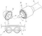
도 1은 본 발명의 바람직한 실시 예에 따른 원형 문합기의 사시도,
도 2는 도 1에 도시된 원형 문합기의 블록 구성도,
도 3은 도 2에 도시된 문합부와 가이드부의 분해 사시도,
도 4는 도 3에 도시된 가이드부가 돌출된 상태를 보인 예시도,
도 5는 원형 문합기의 작동방법을 단계별로 설명하는 동작 상태도.BRIEF DESCRIPTION OF THE DRAWINGS Figure 1 is a perspective view of a circular sealer according to a preferred embodiment of the present invention,
Fig. 2 is a block diagram of the circular mantle shown in Fig. 1,
Fig. 3 is an exploded perspective view of the stiffening portion and the guide portion shown in Fig. 2,
FIG. 4 is an exemplary view showing a state in which the guide portion shown in FIG. 3 is protruded;
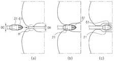
Fig. 5 is an operational state diagram illustrating step-by-step the operation method of the circular insulator. Fig.
이하 본 발명의 바람직한 실시 예에 따른 원형 문합기를 첨부된 도면을 참조하여 상세하게 설명한다.DETAILED DESCRIPTION OF THE PREFERRED EMBODIMENT Hereinafter, a circular sealer according to a preferred embodiment of the present invention will be described in detail with reference to the accompanying drawings.
도 1은 본 발명의 바람직한 실시 예에 따른 원형 문합기의 사시도이고, 도 2는 도 1에 도시된 원형 문합기의 블록 구성도이다.FIG. 1 is a perspective view of a circular sealer according to a preferred embodiment of the present invention, and FIG. 2 is a block diagram of the circular sealer shown in FIG.
이하에서는 '좌측', '우측', '전방', '후방', '상방' 및 '하방'과 같은 방향을 지시하는 용어들은 각 도면에 도시된 상태를 기준으로 각각의 방향을 지시하는 것으로 정의한다.Hereinafter, terms indicating directions such as 'left', 'right', 'forward', 'rearward', 'upward' and 'downward' are defined as indicating respective directions based on the states shown in the respective drawings do.
본 발명의 바람직한 실시 예에 따른 원형 문합기(10)는 도 1 및 도 2에 도시된 바와 같이, 문합 부위에 스테이플을 발사해서 문합 부위를 문합하는 문합부(20), 시술자의 조작에 의해 스테이플을 발사하는 가압력을 발생하는 핸들부(30), 문합부(20)에 마련된 앤빌헤드(22)를 전후 방향으로 이동시키도록 구동력을 발생하는 구동부(40) 및 구동부(40)의 구동을 제어하는 제어부(50)를 포함한다.As shown in FIGS. 1 and 2, the
그리고 본 발명의 바람직한 실시 예에 따른 원형 문합기(10)는 문합부(20)에 마련된 헤드부(22)를 항문을 통해 체내로 삽입하는 과정에서 원활한 삽입이 가능하도록 가이드하는 가이드부(60)를 더 포함한다.The
이와 함께, 본 발명의 바람직한 실시 예에 따른 원형 문합기(10)는 각 장치에 전원을 공급하는 전원부(70) 및 동작 상태를 표시하는 표시부(80)를 더 포함할 수 있다.In addition, the
도 2 내지 도 4를 참조하여 문합부와 가이드부의 구성을 상세하게 설명한다.The construction of the mating portion and the guide portion will be described in detail with reference to Figs. 2 to 4. Fig.
도 3은 도 2에 도시된 문합부와 가이드부의 분해 사시도이고, 도 4는 도 3에 도시된 가이드부가 돌출된 상태를 보인 예시도이다.FIG. 3 is an exploded perspective view of the anchoring portion and the guide portion shown in FIG. 2, and FIG. 4 is an exemplary view showing a state in which the guide portion shown in FIG. 3 is protruded.
문합부(20)는 도 2 및 도 3에 도시된 바와 같이, 내부에 스테이플을 수용하고 구동부(40)에서 제공되는 구동력에 의해 스테이플을 발사하는 헤드부(21)와 헤드부(21) 선단에 결합되는 앤빌헤드(22)를 포함할 수 있다.2 and 3, the
헤드부(21)에는 스테이플이 수용되는 스테이플 수용구(23)가 마련되고, 앤빌헤드(22)에는 발사된 스테이플이 휘어지도록 유도하는 앤빌(24)이 마련될 수 있다.The
스테이플(11)은 대략 'ㄷ' 형상으로 형성되고, 발사 방향과 직각으로 배치되는 베이스바(12)와 베이스바(12)의 양단에 발사 방향을 따라 돌출 형성되는 한 쌍의 돌출바(13)를 포함한다.The
이러한 스테이플(11)은 스테이플 수용구(23)에서 발사되면, 한 쌍의 돌출바(13)가 앤빌(24)에 형성된 한 쌍의 오목부(25)에 접촉되면 오목부(25)의 형상에 따라 휘어진다.When the
즉, 헤드부(21)와 접하는 앤빌헤드(22)의 후단에는 앤빌(24)이 형성되고, 앤빌(24)의 후면에는 헤드부(21)에 형성된 스테이플 수용구(23)에 대응되는 위치에 복수 쌍의 오목홈(24)이 형성될 수 있다.The
여기서, 각 쌍의 오목부(25)는 단면이 반원 형상이 되도록 오목하게 형성되고, 각 쌍의 오목부(25) 사이에는 출몰부(26)가 형성될 수 있다.Here, the concave portions 25 of each pair are concave so as to have a semicircular shape in cross section, and the protruding and recessed portions 26 may be formed between the concave portions 25 of each pair.
출몰부(26)의 양면은 양측에 형성된 한 쌍의 오목부(25)의 곡률에 대응되는 곡률로 형성되고, 출몰부(26)의 최상단은 중앙부보다 넓은 폭으로 형성될 수 있다.The upper and lower surfaces of the protruding and recessed portion 26 may be formed to have a curvature corresponding to the curvature of the pair of recessed portions 25 formed on both sides.
그래서 한 쌍의 돌출바(13)는 각각 한 쌍의 오목부(25) 형상을 따라 먼저 한 쌍의 오목부(25) 사이의 출몰부(26)를 향해 휘어지고, 출몰부(26)로부터 멀어지는 방향으로 휘어지면서 곡면을 형성한 후, 다시 한 쌍의 오목부(25) 형상을 따라 출몰부(26)를 향해 휘어진다.The pair of protruding bars 13 are respectively bent along the shape of the pair of concave portions 25 toward the protruding and retracting portions 26 between the pair of the concave portions 25, And then bent along the shape of the pair of concave portions 25 toward the protruding and retracting portion 26. As shown in Fig.
따라서 한 쌍의 돌출바(13) 선단부는 각각 최종적으로 대략 링 형상으로 말아진다.Accordingly, the tip portions of the pair of projecting bars 13 are finally rolled into a substantially ring shape.
이에 따라, 수술 과정에서 문합하고자 하는 문합 부위의 제1 조직(14)과 제2 조직(15)이 스테이플(11)에 의해 문합될 수 있다.Accordingly, the
이와 함께, 헤드부(21)에는 문합 부위에서 스테이플로 고정될 부분의 내측에 있는 불필요한 부분을 절단하는 커터가 마련될 수 있다.In addition, the
그리고 헤드부(21)의 선단에는 투관침(27)이 마련되고, 앤빌헤드(22)의 후단에는 투관침(27)에 결합되는 앤빌샤프트(28)가 마련될 수 있다.A
그래서 헤드부(21)와 앤빌헤드(22)는 서로 문합하고자 하는 문합 부위의 제1 조직 측에 헤드부(21)를 배치하고, 제2 조직 측에 앤빌헤드(22)를 배치한 상태에서 투관침(27)과 앤빌샤프트(28)를 결합하여 서로 결합될 수 있다.The
문합부(20)의 헤드부(21)와 핸들부(30)는 파이프 형상으로 형성되는 연결부재(32)로 연결되고, 연결부재(32) 내부에는 아래에서 설명할 구동부(40)의 앤빌헤드 구동축(42)과 핸들부(30)의 스테이플 구동축(34) 및 가이드부(60)의 가이드 구동축(64)이 설치될 수 있다.The
가이드부(60)는 도 3 및 도 4에 도시된 바와 같이, 항문을 통해 체내로 원활하게 삽입할 수 있도록 선단이 뾰쪽한 원뿔 형상으로 형성될 수 있다.As shown in FIGS. 3 and 4, the
상세하게 설명하면, 가이드부(60)는 헤드부(21)의 선단부에 출몰 가능하게 설치되는 출몰부(61), 출몰부(61)의 후단에 연결되는 연결부(62) 및 연결부(62)의 후단에 연결되고 출몰부(61)가 출몰 동작하도록 구동력을 발생하는 구동모듈(63)을 포함할 수 있다.More specifically, the
출몰부(61)는 체내 삽입시 항문에 원활하게 삽입 가능하도록 가이드하기 위해, 연결부(62)의 선단으로부터 멀어질수록 직경이 작아지는 대략 원뿔 형상이나 유선 형상으로 형성될 수 있다.The protruding and retracting
이러한 출몰부(61)의 외면에는 가이드부(60)의 길이 방향을 따라 복수의 절개공(66)이 형성될 수 있다.A plurality of cut-out
각 절개공(66)은 출몰부(61)의 길이 전체에 걸쳐 동일한 간격으로 규칙적으로 형성될 수 있다.Each of the cut-out
이와 같이 출몰부(61)의 외면에 복수의 절개공(66)이 형성됨에 따라, 출몰부(61)는 헤드부(21)의 선단에서 돌출시 하나로 연결되고, 항문 내측으로 헤드부(21)의 삽입이 완료되면 복수의 절개공에 의해 복수의 분할판(67)으로 분할되어 헤드부(21)의 내부로 이동해서 수용될 수 있다.The plurality of cut-
도 4에는 절개공(66)이 6개로 도시되어 있으나, 본 발명은 반드시 이에 한정되는 것은 아니며, 헤드부(21)의 직경, 출몰부(61)의 길이나 직경 등에 따라 절개공(66)의 개수를 다양하게 변경할 수 있다.The number of cut-out
연결부(62)는 대략 원통 형상으로 형성되고, 헤드부(21)의 내부에 구동모듈(63)로부터 전달되는 구동력에 의해 전후 방향을 따라 이동 가능하게 설치될 수 있다.The
한편, 출몰부(61)와 연결부(62)가 연결되는 부분에는 출몰부(61)의 외측단과 헤드부(21)의 선단면 외측단 사이의 단차로 인한 통증 유발을 방지하는 환형 리브(68)가 형성될 수 있다.An
환형 리브(68)는 도 4에 도시된 바와 같이, 단면이 대략 삼각 형상이나 반원 형상으로 형성될 수 있다.The
이와 같이 형성되는 환형 리브(68)는 출몰부(61)가 헤드부(21) 내부 공간에 수용되면 넓게 펴지도록 탄성 변형되고, 출몰부(61)가 헤드부(21) 전방으로 돌출되면 본래의 형상으로 복원되어 출몰부(61)의 외측단과 헤드부(21)의 선단면 외측단 사이의 단차를 메워 제거할 수 있다.The
구동모듈(63)은 연결부(62)의 후단에 연결되는 가이드 구동축(64)과 시술자의 조작에 의한 조작력을 가이드 구동축(64)에 전달하는 조작레버(65)를 포함할 수 있다.The
가이드 구동축(64)은 연결부재(32) 내부에 설치되고, 조작레버(65)는 핸들부(30)의 일측면에 마련되어 시술자의 전후 방향 조작에 의해 직선운동하도록 가해지는 조작력을 가이드 구동축(64)으로 전달할 수 있다.The
이를 위해, 핸들부(30)의 일측면에는 조작레버(65)가 직선이동하는 하는 이동공(36)과 이동공(36)의 선단부에 직각으로 연결되고 전방으로 이동한 조작레버(65)를 고정하는 고정공(37)이 형성될 수 있다(도 1 참조).To this end, one side of the
따라서 시술자는 조작레버(65)를 전방으로 가압해서 출몰부(61)를 전방으로 돌출시킨 상태에서 출몰부(61)와 헤드부(61)를 항문에 삽입하고, 헤드부(21)가 항문 내측으로 삽입된 후, 조작레버(65)를 후방으로 가압해서 출몰부(61)를 헤드부 내부에 수용시킬 수 있다.Therefore, the practitioner inserts the protruding and retreating
여기서, 시술자는 이동공(36)의 선단부와 연결되어 고정공(37)이 직각으로 형성됨에 따라, 출몰부(61)를 전방으로 돌출된 상태에서 조작레버(65)를 손으로 고정할 필요없이, 조작레버(65)를 고정공(37)에 위치시켜 고정하고, 출몰부(61)와 헤드부(21)를 항문 내측으로 삽입하는 작업을 용이하게 수행할 수 있다.Here, the practitioner is connected to the distal end of the moving hole 36 so that the fixing
한편, 본 실시 예에서는 핸들부(30)에 조작레버(65)를 마련해서 시술자가 직접 조작레버(65)를 가압 조작해서 출몰부(61)를 돌출시키거나 헤드부(21) 내부에 수용하는 것으로 설명하였으나, 본 발명은 반드시 이에 한정되는 것은 아니다.In the present embodiment, on the other hand, the
즉, 본 발명은 구동모듈(60)에 시술자의 조작에 따라 조작신호를 입력받는 조작버튼(도면 미도시)과 상기 조작신호가 입력되면 전원부(70)로부터 전원을 공급받아 정회전 또는 역회전해서 구동력을 발생하는 모터(도면 미도시)를 적용하도록 변경될 수 있다.That is, according to the present invention, the
따라서 본 발명은 시술자가 직접 조작레버를 조작할 필요없이, 모터의 구동력을 이용해서 가이드부에 마련된 출몰부를 전방으로 돌출시키거나 헤드부 내부로 이동시켜 수용할 수 있다.Therefore, according to the present invention, the surgeon provided in the guide portion can be protruded forward or moved into the head portion by using the driving force of the motor, without the operator needing to operate the operation lever directly.
다시 도 1 및 도 2에서, 핸들부(30)는 시술자의 회전 조작에 의해 가압력을 발생하는 레버(31) 및 레버(31)로부터 가압력을 전달받아 스테이플 수용구(23)에 수용된 스테이플(11)을 앤빌(24) 측으로 가압해서 발사하도록 가압력을 전달하는 스테이플 구동축(34)을 포함할 수 있다.1 and 2, the
그리고 핸들부(30) 내부에는 구동부(40)와 제어부(50) 및 전원부(70)가 마련되고, 핸들부(30)의 외면에는 가이드부(60)의 조작레버(65)와 표시부(80)가 마련될 수 있다.A
레버(31)에는 레버(31)의 회전을 차단 또는 해제하는 안전클립(33)이 설치되고, 레버(31)와 스테이플 구동축 사이에는 레버(31)의 회전운동을 직선운동으로 전환하는 제1 동력변환유닛(35)이 마련될 수 있다.The
제1 동력변환유닛(35)은 샤프트와 기어 등을 조합해서 구성될 수 있다.The first
구동부(40)는 전원부(70)에서 전원을 공급받아 구동되는 구동모터(41) 및 구동모터(41)에서 발생한 구동력을 전달받아 투관침(27)으로 전달해서 투관침(27)에 결합된 앤빌헤드(22)를 전후 방향으로 직선운동시키는 앤빌헤드 구동축(42)을 포함할 수 있다.The driving
구동모터(31)의 출력축과 앤빌헤드 구동축(42) 사이에는 기어나 샤프트 등으로 구성되어 구동모터(31)의 회전운동을 직선운동으로 변환하는 제2 동력변환유닛(53)이 마련될 수 있다.A second power converting unit 53 composed of a gear, a shaft, or the like may be provided between the output shaft of the
제어부(50)는 앤빌헤드(22)를 전후 방향을 이동시켜 헤드부(21)와 앤빌헤드(22)의 사이의 거리를 조절하도록 구동부(40)의 구동을 제어한다.The
그리고 제어부(50)는 가이드부(60)의 구동모듈(63)에 상기 모터가 적용되는 경우, 상기 조작버튼을 통해 조작신호가 입력되면, 상기 모터를 구동해서 출몰부(61)를 전방으로 돌출시키거나 헤드부(21) 내부로 수용하도록 상기 모터의 구동을 제어할 수 있다.When the motor is applied to the
다음, 도 5를 참조하여 본 발명의 바람직한 실시 예에 따른 원형 문합기의 작동방법을 상세하게 설명한다.Next, a method of operating the circular sealer according to a preferred embodiment of the present invention will be described in detail with reference to FIG.
도 5는 원형 문합기의 작동방법을 단계별로 설명하는 동작 상태도이다.5 is an operational state diagram for explaining a step-by-step operation method of the circular knit machine.
도 5의 (a)에서 항문(H)의 직경(DH)은 헤드부의 외경(D0)보다 상당히 작다.In FIG. 5A, the diameter DH of the anus H is considerably smaller than the outer diameter D0 of the head portion.
따라서 시술자는 항문(H)에 마찰 감소용 물질을 바른 후, 항문(H) 내측으로 앤빌헤드를 삽입하고, 조작레버(65)를 전방으로 가압 조작해서 헤드부(21)의 선단에서 전방으로 가이드부(60)의 출몰부(61)를 돌출시킨다.Therefore, the practitioner inserts the anvil head into the anus H after applying the friction reducing material to the anus H and pushes the
이때, 출몰부(61)는 가이드 구동축(64)과 연결부(62)의 전진 이동에 의해 헤드부(21)의 선단에서 전방으로 돌출된다.At this time, the protruding / retracting
이어서, 시술자는 출몰부(61)를 항문(H)에 접촉시켜 가압하면, 도 5의 (b)에 도시된 바와 같이 출몰부(61)와 헤드부(21)를 항문(H) 내로 원활하게 삽입할 수 있다.5 (b), when the surgeon presses the
이때, 출몰부(61)의 항문 삽입시, 항문(H)의 직경(DH)은 유선형의 출몰부(61)에 의해 헤드부(21)의 외경(DO)에 이르도록 점차적으로 확장된다.At this time, the diameter DH of the anus H gradually expands to reach the outer diameter DO of the
그래서 헤드부(21)는 도 5의 (c)에 도시된 바와 같이, 원활하게 항문(H)을 통과하여 항문 내측으로 삽입될 수 있다.Thus, as shown in Fig. 5 (c), the
이와 같이 헤드부(21)가 항문 내측으로 삽입되면, 시술자는 조작레버(65)를 후방으로 가압 조작하고, 가이드부(60)의 출몰부(61)는 가이드 구동축(64)과 연결부(62)의 후진 이동에 의해 헤드부(21)의 내부 공간으로 이동해서 수용된다.When the
이후, 시술자는 체내로 삽입된 원형 문합기(10)를 이용해서 본격적인 문합 수술을 진행할 수 있다.Thereafter, the practitioner can perform a full-scale anastomosis operation using the
상기한 바와 같은 과정을 통하여, 본 발명은 항문을 통해 원형 문합기의 헤드부를 삽입하는 과정에서 헤드부의 선단에 가이드부를 돌출시켜 원활하게 삽입할 수 있게 한다.In the course of inserting the head portion of the circular miter into the anus through the ankle, the guide portion is protruded to the front end of the head portion so as to be smoothly inserted.
이상 본 발명자에 의해서 이루어진 발명을 상기 실시 예에 따라 구체적으로 설명하였지만, 본 발명은 상기 실시 예에 한정되는 것은 아니고, 그 요지를 이탈하지 않는 범위에서 여러 가지로 변경 가능한 것은 물론이다.Although the invention made by the present inventors has been described concretely with reference to the above embodiments, the present invention is not limited to the above embodiments, and it goes without saying that various changes can be made without departing from the gist of the present invention.
본 발명은 항문을 통해 원형 문합기의 헤드부를 삽입하는 과정에서 헤드부의 선단에 가이드부를 돌출시켜 원활하게 삽입하는 원형 문합기 기술에 적용된다.The present invention is applied to a circular knitting machine in which a guide portion is inserted into a front end of a head portion in a process of inserting a head portion of a circular knit machine through an anus, thereby smoothly inserting the guide portion.
10: 원형 문합기
11: 스테이플12: 베이스바
13: 돌출바14,15: 제1,제2 조직
20: 문합부21: 헤드부
22: 앤빌헤드23: 스테이플 수용구
24: 앤빌25: 오목부
26: 출몰부27: 투관침
28: 앤빌샤프트30: 핸들부
31: 레버32: 연결부재
33: 안전클립34: 스테이플 구동축
35: 제1 동력변환유닛36: 이동공
37: 고정공40: 구동부
41: 구동모터42: 앤빌헤드 구동축
43: 제2 동력변환유닛50: 제어부
60: 가이드부61: 출몰부
62: 연결부63: 구동모듈
64: 가이드 구동축65: 조작레버
66: 절개공67: 분할판
68: 환형 리브70: 전원부
80: 표시부10: Circular Archer
11: staple 12: base bar
13: protruding
20: an opening part 21: head part
22: anvil head 23: staple receiver
24: Anvil 25:
26: Appearance section 27: Trooper
28: anvil shaft 30: handle portion
31: lever 32: connecting member
33: safety clip 34: staple drive shaft
35: first power converting unit 36: moving ball
37: Fixing hole 40: Driving part
41: drive motor 42: anvil head drive shaft
43: second power converting unit 50:
60: guide portion 61:
62: connection part 63: drive module
64: Guide drive shaft 65: Operation lever
66: incision hole 67: partition plate
68: annular rib 70:
80:
Claims (6)
Translated fromKorean시술자의 조작에 의해 스테이플을 발사하는 가압력을 발생하는 핸들부,
상기 문합부에 마련된 앤빌헤드를 전후 방향으로 이동시키도록 구동력을 발생하는 구동부 및
상기 문합부에 마련된 헤드부를 항문을 통해 체내로 삽입하도록 가이드하는 가이드부를 포함하고,
상기 가이드부는 유선 형상이나 원뿔 형상으로 형성되어 상기 헤드부의 선단에 출몰 가능하게 마련되는 출몰부를 포함하는 것을 특징으로 하는 원형 문합기.An anastomotic site that fires staples at an anastomotic site and anastomoses the anastomotic site,
A handle portion for generating a pressing force for emitting a staple by an operation of a practitioner,
A driving part for generating a driving force to move the anvil head provided in the striking part in the forward and backward directions,
And a guide portion for guiding insertion of the head portion provided in the mating portion into the body through the anus,
Wherein the guide portion includes a protruding portion formed in a wired or conical shape and provided so as to protrude / retract at a front end of the head portion.
상기 가이드부는 상기 출몰부의 후단에 연결되는 연결부 및
상기 연결부의 후단에 연결되고 상기 출몰부가 출몰 동작하도록 구동력을 발생하는 구동모듈을 포함하고,
상기 출몰부의 외면에는 상기 가이드부의 길이 방향을 따라 복수의 절개공이 형성되는 것을 특징으로 하는 원형 문합기.The method according to claim 1,
The guide portion includes a connection portion connected to the rear end of the appearance and appearance portion,
And a driving module connected to a rear end of the connection portion and generating a driving force to move the protruding /
Wherein a plurality of cut-out holes are formed in an outer surface of the protruding and recessed portion along a longitudinal direction of the guide portion.
상기 구동부의 구동을 제어하는 제어부,
상기 원형 문합기에 마련된 각 장치에 전원을 공급하는 전원부 및
상기 원형 문합기의 동작 상태를 표시하는 표시부를 더 포함하는 것을 특징으로 하는 원형 문합기.3. The method of claim 2,
A control unit for controlling driving of the driving unit,
A power supply unit for supplying power to each device provided in the circular combiner;
Further comprising a display unit for displaying an operation state of the circular sealer.
상기 연결부의 후단에 연결되는 가이드 구동축과
시술자의 전후 방향 조작에 의한 조작력을 상기 가이드 구동축에 전달하는 조작레버를 포함하는 것을 특징으로 하는 원형 문합기.4. The apparatus of claim 2 or 3, wherein the drive module
A guide driving shaft connected to a rear end of the connecting portion,
And an operation lever for transmitting an operation force of the operator in the forward and backward directions to the guide drive shaft.
상기 구동모듈은 상기 구동모듈은 상기 연결부의 후단에 연결되는 가이드 구동축,
시술자의 조작에 따라 조작신호를 입력받는 조작버튼 및
상기 조작신호가 입력되면 전원을 공급받아 정회전 또는 역회전해서 구동력을 발생하는 모터를 포함하고,
상기 제어부는 상기 조작신호에 따라 상기 모터를 정회전 또는 역회전하도록 구동을 제어하는 제어신호를 발생하는 것을 특징으로 하는 원형 문합기.The method of claim 3,
Wherein the driving module includes a guide driving shaft connected to a rear end of the connecting portion,
An operation button for inputting an operation signal in accordance with an operation of a practitioner, and
And a motor for receiving a power supply and generating a driving force by forward rotation or reverse rotation when the operation signal is inputted,
Wherein the control unit generates a control signal for controlling the motor to rotate forward or reverse in accordance with the operation signal.
상기 출몰부와 연결부가 연결되는 부분에는 상기 출몰부의 외측단과 상기 헤드부의 선단면 외측단 사이의 단차를 메우는 환형 리브가 형성되는 것을 특징으로 하는 원형 문합기.3. The method of claim 2,
Wherein an annular rib is formed at a portion where the protruding portion and the connection portion are connected to each other to fill a gap between an outer end of the outer circumferential portion and an outer end of the distal end of the head portion.
Priority Applications (1)
| Application Number | Priority Date | Filing Date | Title |
|---|---|---|---|
| KR1020170115279AKR102021430B1 (en) | 2017-09-08 | 2017-09-08 | Circular anastomosis stampling instrument |
Applications Claiming Priority (1)
| Application Number | Priority Date | Filing Date | Title |
|---|---|---|---|
| KR1020170115279AKR102021430B1 (en) | 2017-09-08 | 2017-09-08 | Circular anastomosis stampling instrument |
Publications (2)
| Publication Number | Publication Date |
|---|---|
| KR20190028165Atrue KR20190028165A (en) | 2019-03-18 |
| KR102021430B1 KR102021430B1 (en) | 2019-09-16 |
Family
ID=65949222
Family Applications (1)
| Application Number | Title | Priority Date | Filing Date |
|---|---|---|---|
| KR1020170115279AExpired - Fee RelatedKR102021430B1 (en) | 2017-09-08 | 2017-09-08 | Circular anastomosis stampling instrument |
Country Status (1)
| Country | Link |
|---|---|
| KR (1) | KR102021430B1 (en) |
Cited By (1)
| Publication number | Priority date | Publication date | Assignee | Title |
|---|---|---|---|---|
| WO2025164937A1 (en)* | 2024-02-02 | 2025-08-07 | 고려대학교 산학협력단 | Anastomosis device having new arrangement for improving end-to-end anastomosis of intestines |
Citations (7)
| Publication number | Priority date | Publication date | Assignee | Title |
|---|---|---|---|---|
| US5205459A (en) | 1991-08-23 | 1993-04-27 | Ethicon, Inc. | Surgical anastomosis stapling instrument |
| US5392979A (en) | 1987-05-26 | 1995-02-28 | United States Surgical Corporation | Surgical stapler apparatus |
| JPH09289991A (en)* | 1996-04-26 | 1997-11-11 | Olympus Optical Co Ltd | Suture device for medical treatment |
| KR100769681B1 (en)* | 2006-05-15 | 2007-10-23 | 고려대학교 산학협력단 | Circular anastomizer |
| JP2009072599A (en)* | 2007-09-24 | 2009-04-09 | Tyco Healthcare Group Lp | Insertion shroud for surgical instrument |
| KR20110109531A (en)* | 2010-03-31 | 2011-10-06 | 인제대학교 산학협력단 | Insertion aid for circular anastomosis |
| JP2012505725A (en)* | 2008-10-16 | 2012-03-08 | エシコン・エンド−サージェリィ・インコーポレイテッド | Surgical stapling instrument having apparatus for providing anvil position feedback |
- 2017
- 2017-09-08KRKR1020170115279Apatent/KR102021430B1/ennot_activeExpired - Fee Related
Patent Citations (7)
| Publication number | Priority date | Publication date | Assignee | Title |
|---|---|---|---|---|
| US5392979A (en) | 1987-05-26 | 1995-02-28 | United States Surgical Corporation | Surgical stapler apparatus |
| US5205459A (en) | 1991-08-23 | 1993-04-27 | Ethicon, Inc. | Surgical anastomosis stapling instrument |
| JPH09289991A (en)* | 1996-04-26 | 1997-11-11 | Olympus Optical Co Ltd | Suture device for medical treatment |
| KR100769681B1 (en)* | 2006-05-15 | 2007-10-23 | 고려대학교 산학협력단 | Circular anastomizer |
| JP2009072599A (en)* | 2007-09-24 | 2009-04-09 | Tyco Healthcare Group Lp | Insertion shroud for surgical instrument |
| JP2012505725A (en)* | 2008-10-16 | 2012-03-08 | エシコン・エンド−サージェリィ・インコーポレイテッド | Surgical stapling instrument having apparatus for providing anvil position feedback |
| KR20110109531A (en)* | 2010-03-31 | 2011-10-06 | 인제대학교 산학협력단 | Insertion aid for circular anastomosis |
Cited By (1)
| Publication number | Priority date | Publication date | Assignee | Title |
|---|---|---|---|---|
| WO2025164937A1 (en)* | 2024-02-02 | 2025-08-07 | 고려대학교 산학협력단 | Anastomosis device having new arrangement for improving end-to-end anastomosis of intestines |
Also Published As
| Publication number | Publication date |
|---|---|
| KR102021430B1 (en) | 2019-09-16 |
Similar Documents
| Publication | Publication Date | Title |
|---|---|---|
| EP2283784B1 (en) | Surgical system for natural orifice transluminal endoscopic surgery (notes) | |
| US10595873B2 (en) | Surgical staplers and related methods | |
| US9463023B2 (en) | Surgical instrument with elongated channel | |
| US8136712B2 (en) | Surgical stapler with discrete staple height adjustment and tactile feedback | |
| JP4510001B2 (en) | Driving force transmission along a bending instrument | |
| US5782397A (en) | Stapling device | |
| US10076332B2 (en) | Methods for applying surgical staples to internal walls of hollow tissue organs | |
| JPH0511982B2 (en) | ||
| BRPI0713913B1 (en) | surgical stapling instrument | |
| CA2749709A1 (en) | Surgical stapling device for performing circular anastomosis and surgical staples for use therewith | |
| MXPA04009610A (en) | Applier for fastener for single lumen access anastomosis. | |
| KR102072045B1 (en) | C-shaped hemorrhoidal stapler | |
| JP2012205718A (en) | Lumen anastomosis device | |
| KR20190028165A (en) | Circular anastomosis stampling instrument | |
| CN217853123U (en) | Outward turning type stitching instrument | |
| KR20190028164A (en) | Circular anastomosis stampling instrument and compression strength contol method thereof | |
| JP5236817B2 (en) | Apparatus and method for excision and closure of hollow organs | |
| US20220395275A1 (en) | Surgical fastening instrument | |
| CN115120293A (en) | Actuating mechanism for outward turning type stitching instrument, stitching instrument and quality inspection method of stitching instrument | |
| CN214966105U (en) | surgical stapler | |
| KR101945247B1 (en) | Stapling device using of stent for laparoscopic surgery | |
| CN217987637U (en) | Stitching instrument | |
| KR102105572B1 (en) | A mounting tool for an anastomotic device | |
| KR20200018033A (en) | Intraluminal surgical stapler | |
| RU183782U1 (en) | CIRCULAR SEWING MACHINE FOR APPLICATION OF THE INTESTINO-OESOPHINE ANASTOMOSIS |
Legal Events
| Date | Code | Title | Description |
|---|---|---|---|
| A201 | Request for examination | ||
| PA0109 | Patent application | St.27 status event code:A-0-1-A10-A12-nap-PA0109 | |
| PA0201 | Request for examination | St.27 status event code:A-1-2-D10-D11-exm-PA0201 | |
| P11-X000 | Amendment of application requested | St.27 status event code:A-2-2-P10-P11-nap-X000 | |
| P13-X000 | Application amended | St.27 status event code:A-2-2-P10-P13-nap-X000 | |
| D13-X000 | Search requested | St.27 status event code:A-1-2-D10-D13-srh-X000 | |
| D14-X000 | Search report completed | St.27 status event code:A-1-2-D10-D14-srh-X000 | |
| E902 | Notification of reason for refusal | ||
| PE0902 | Notice of grounds for rejection | St.27 status event code:A-1-2-D10-D21-exm-PE0902 | |
| PG1501 | Laying open of application | St.27 status event code:A-1-1-Q10-Q12-nap-PG1501 | |
| E13-X000 | Pre-grant limitation requested | St.27 status event code:A-2-3-E10-E13-lim-X000 | |
| P11-X000 | Amendment of application requested | St.27 status event code:A-2-2-P10-P11-nap-X000 | |
| P13-X000 | Application amended | St.27 status event code:A-2-2-P10-P13-nap-X000 | |
| E701 | Decision to grant or registration of patent right | ||
| PE0701 | Decision of registration | St.27 status event code:A-1-2-D10-D22-exm-PE0701 | |
| GRNT | Written decision to grant | ||
| PR0701 | Registration of establishment | St.27 status event code:A-2-4-F10-F11-exm-PR0701 | |
| PR1002 | Payment of registration fee | St.27 status event code:A-2-2-U10-U11-oth-PR1002 Fee payment year number:1 | |
| PG1601 | Publication of registration | St.27 status event code:A-4-4-Q10-Q13-nap-PG1601 | |
| PN2301 | Change of applicant | St.27 status event code:A-5-5-R10-R13-asn-PN2301 St.27 status event code:A-5-5-R10-R11-asn-PN2301 | |
| PR1001 | Payment of annual fee | St.27 status event code:A-4-4-U10-U11-oth-PR1001 Fee payment year number:4 | |
| PR1001 | Payment of annual fee | St.27 status event code:A-4-4-U10-U11-oth-PR1001 Fee payment year number:5 | |
| PC1903 | Unpaid annual fee | St.27 status event code:A-4-4-U10-U13-oth-PC1903 Not in force date:20240907 Payment event data comment text:Termination Category : DEFAULT_OF_REGISTRATION_FEE | |
| PC1903 | Unpaid annual fee | St.27 status event code:N-4-6-H10-H13-oth-PC1903 Ip right cessation event data comment text:Termination Category : DEFAULT_OF_REGISTRATION_FEE Not in force date:20240907 |